

Page 1

PRE-DELIVERY
How to make delivery and
installation of your new hot tub
fast, easy and trouble-free.
Page 2

Important Pre-Delivery Information
Please read this booklet before your scheduled delivery day.
Record your spa information below and then store this booklet in a place you can easily
find it. If service is required, your dealer will ask for these details.
Spa Model
Spa Serial Number
Date Purchased
Date Installed
Spa Dealer’s Name
Spa Dealer’s Phone #
Spa Dealer’s Address
+
To Keep
Warranty Valid
Note
Note
Most cities and counties require permits for exterior construction and
electrical circuits. In addition, some communities have codes requiring
residential barriers such as fencing and/or self-closing gates on the
property to prevent unsupervised access to a spa by children. Your
Sundance dealer can provide information on which permits may be
required and how to obtain them prior to delivery of your spa.
The specifications published in the Spa Dimensions and Specifications
section of this book are approximate. Always measure your spa before
making critical design or delivery decisions.
Consult your local state or city building ordinances to ensure
installation is in accordance with local codes. The spa’s
warranty becomes void if these guidelines are not followed.
Page 3

Congratulations!
You’ve purchased a Sundance® spa, made to exacting ISO 9001 quality standards.
With a little preparation and care, your spa will give you many years of enjoyment. This
booklet has been designed to provide you with all the information you’ll need to ensure
a safe, speedy, and trouble-free spa delivery and installation.
Table of Contents
Important Pre-Delivery Information ........................................................................................ ii
Planning the Best Location for Your Spa ...............................................................................2
Planning to Move the Spa Into Your Yard ............................................................................... 6
Electrical Tasks Before Spa Delivery ...................................................................................... 8
Power Congurations for 880 Maxxus Models (North America, 60Hz) .............................. 10
Power Congurations for 880 Altamar, Cameo, Majesta, Marin, and Optima Models
(North America, 60Hz) ...................................................................................................... 11
Power Congurations for 880 Capri Models (North America, 60Hz) ..................................12
Power Congurations for 780 Dover Models (North America, 60Hz) .................................13
Power Congurations for 780 Camden Models (North America, 60Hz) .............................14
Power Congurations for 780 Certa, Chelsee, and Hamilton Models
(North America, 60Hz) ....................................................................................................... 15
Power Congurations for 680 Hartford, and Hawthorne Models (North America, 60Hz) ... 16
Power Congurations for 680 Burlington Models (North America, 60Hz) ..........................17
Power Congurations for 680 Denali and Tacoma Models (North America, 60Hz) ...........18
Electrical Tasks After Spa Delivery ....................................................................................... 19
Installing a 3-Wire 240 VAC Connection for 880 Altamar, Cameo, Capri, Majesta, Marin,
Maxxus, Optima Models, 780 Camden, Certa, Chelsee, Hamilton Models, and 680
Burlington, Hartford and Hawthorne Models .....................................................................20
Installing a 3-Wire 120 VAC or 4-Wire 120/240 VAC Connection for 780 Dover Models,
680 Denali, Tacoma Models ...............................................................................................21
Final Electrical Connections .................................................................................................22
Connection Conguration #1 ............................................................................................23
240 VAC Connections for 880 Altamar, Cameo, Capri, Majesta, Marin, Optima, Maxxus,
780 Camden, Certa, Chelsee, Hamilton Models, 680 Burlington, Hartford, Hawthorne
Models (North America 60 Hz) ........................................................................................... 23
Connection Conguration #2 ............................................................................................24
120 VAC Connections for Denali, Dover, Tacoma Models (North America 60 Hz) ............24
Connection Conguration #3 ............................................................................................25
240 VAC Connections for Denali, Dover, Tacoma Models (North America 60 Hz) ............25
Spa Dimensions and Specifications ..................................................................................... 26
Useful Details About the Spa ............................................................................................. 26
1
Page 4
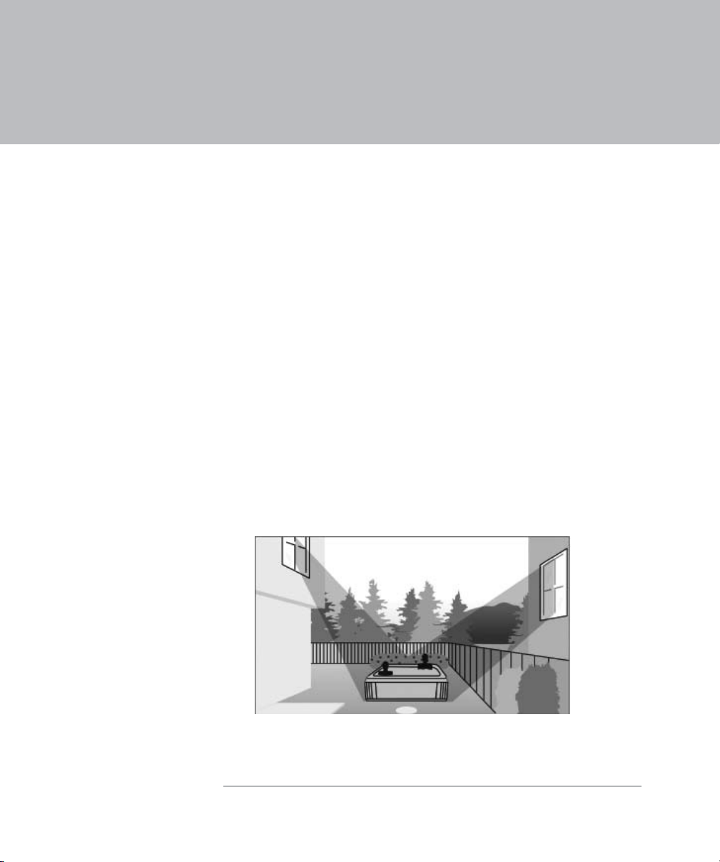
Planning the Best Location for Your Spa
Now that you have purchased your hot tub, you need to decide where to install it. Do you
want to install it outside or inside? There are many factors to take into consideration when
making these location decisions. Answering the questions in this section can help you
make the right choices.
Suggestions for Outdoor Spa Installation
Where should I install
the spa?
When deciding where to place your spa, it should be:
Moved away from overhead power lines. A minimum of r
10 feet (3 meters) is suggested.
Placed to face a view you enjoy. Do you have a special r
landscaped area in your yard that you find pleasant?
Located in an area that gives you the best privacy r
options. Think of the spa’s surroundings during all
seasons when making your choice. During cold, winter
weather, bare trees won’t provide much privacy.
Locate your spa in a sheltered location to protect yourself r
from the wind and harsh weather while bathing in your spa.
This reduces the cost of spa operation and maintenance.
Figure 1 Plan for privacy before the spa is delivered
Continued on next page
2
Page 5
Planning the Best Location for Your Spa, Continued
What kind of
foundation is
available?
Which is best?
Because of the combined weight of the spa, water, and bathers, it is
extremely important that the base upon which the spa rests can uniformly
support this weight without shifting or settling for the entire time the spa
is in place. The base should be smooth, flat, and level.
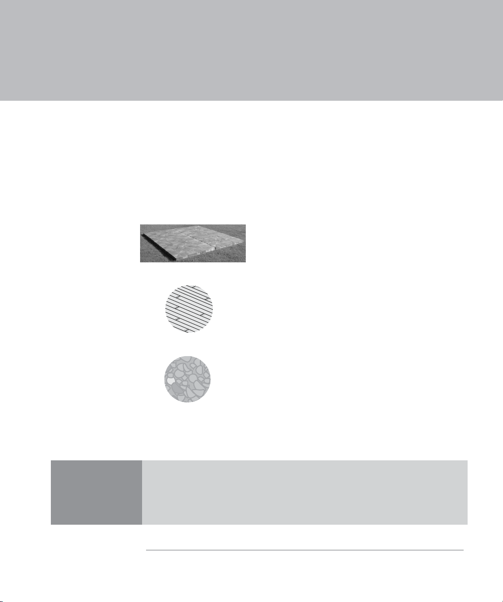
We suggest the following pads:
Good
Synthetic spa pads can be purchased from
your Sundance dealer. These pads can be
placed on a smooth, flat, and level surface.
Better
Wood decking with a concrete foundation.
Recommended
Concrete pad (4 in. [10 cm] or thicker). We
recommend a poured, reinforced concrete slab
with a minimum thickness of 4 in. (10 cm).
Note
If the spa is placed on a surface which does not meet these
requirements, damage to the skirt and/or the spa shell may result.
Damage caused by an improper foundation is not covered under
warranty. It is your responsibility to assure the integrity of the
support at all times.
Continued on next page
3
Page 6

Planning the Best Location for Your Spa,
Continued
How will I use the spa?
Does the climate I live
in make any difference
to where I install my
spa?
What about spa
servicing?
Consider how you intend to use your spa.
If using the spa for … Then …
Family recreation Leave plenty of room around the spa for
activities and yard furniture.
Relaxation and therapy Create a quiet and relaxing environment
around the spa.
When deciding the best place to install the spa, consider
If your climate is … Then consider installing …
Cold and snowy in winter
and warm in summer
Warm in winter and hot in
summer
The spa close to the back door or near
the pool house for fast access to a warm
room
A patio cover or perhaps a gazebo to
provide shade
At some time, a service technician may need to access the spa’s
equipment from below or by removing the side access panels.
To make access easy, create an installation plan that includes
the details for removing the spa’s access panel to easily reach
the spa’s equipment and control panel. Depending upon your
type of installation, keep in mind that the spa might sometime
need to be moved or lifted from the ground.
What other issues
should I consider?
4
When selecting the ideal outdoor location for your spa, consider
these suggestions:
❐ Keep the pathway to your spa free of debris to prevent dirt
and leaves from being tracked into the spa.
❐ Prevent leaves and bits of plants from dropping in the spa
by keeping trees and shrubbery away from the spa.
Page 7

Planning the Best Location for Your Spa, Continued
Suggestions for Indoor Spa Installation
If you are installing your spa indoors, take into consideration your answers to the questions
below.
What are the
issues I need to
think about when
installing a spa
indoors?
What do I need
to know about
installing a spa on
the second oor.
What about spa
servicing?
How can I
ventilate the
spa area?
When installing a spa indoors, it is extremely important to build into your
plan a method of handling any excess water. Consider:
❐ How should water spills be handled?
❐ How many drains should be installed?
❐ What is the best flooring to install near the spa?
❐ If a leak occurs, can the floor handle the entire contents of the
spa?
❐ Will the furniture and walls around my spa withstand and resist
water and moisture?
❐ What provisions should I make for the ceiling and structures that
may be below the spa.
If the spa is being installed on a second story or higher, consult a
structural engineer to discuss the best way to support the spa. Special
attention is needed to plan for a spa installed on a balcony or roof.
Most spa servicing is performed on the spa equipment that is located
behind the panels of the spa. It is important to install the spa to allow
easy access to the spa equipment.
When the spa is in use, considerable amounts of moisture/water are
present. Over time, this moisture may cause mold and mildew and
damage to certain surfaces and/or surroundings. Proper ventilation
should be discussed with an engineer who understands the necessity
of venting moist and heated air that is associated with chemical
emissions.
What warranty
considerations
are important?
Consult your local state or city building ordinances to ensure installation
is in accordance with local codes. Any damage caused if you do not
follow these guidelines voids the spa’s warranty.
5
Page 8

Planning to Move the Spa Into Your Yard
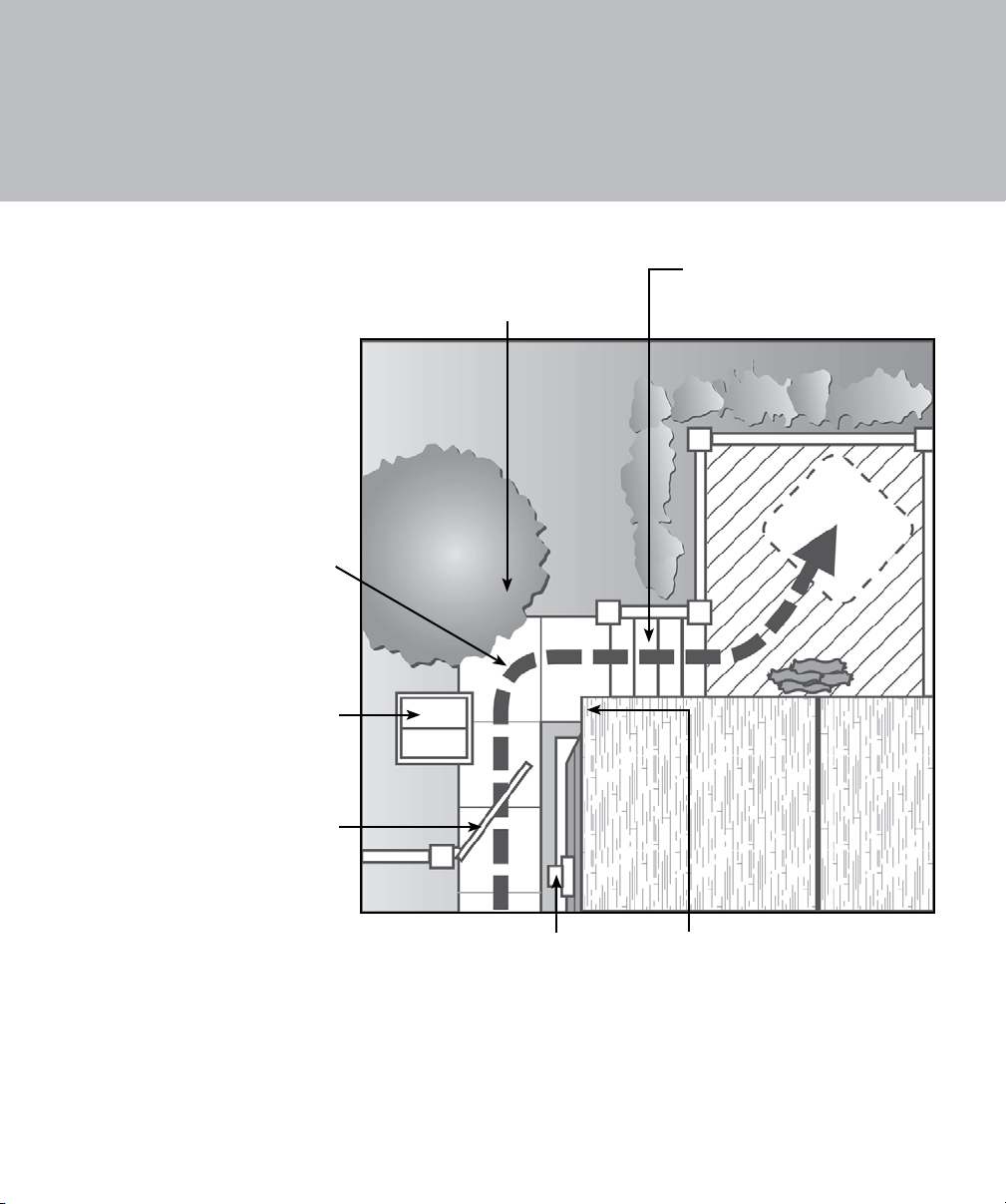
Use the information below, in Figure 2, and in the Spa Dimensions and Specifications
chart to plan the delivery of your spa into your yard. The Spa Dimensions and
Specifications chart list your spa model and its dimensions
Check your spa’s
dimensions
Plan the delivery
route
Use a crane
Check the width of gates, doors, and sidewalks to make sure your
spa will pass through unobstructed.
During delivery, the spa must remain on the delivery cart at all
times. You may have to remove a gate or part of a fence to allow
an unobstructed passageway to the installation location.
After referring to Figure 2, plan your spa’s delivery route into your
yard. Check off each item on the checklist below to verify your
plans.
❐ If the delivery route requires a 90° turn, check the
measurements at the turn to ensure the spa will fit.
❐ Are there protruding gas or water meters, or A/C units
obstructing the delivery path to your yard?
❐ Are there low roof eaves, overhanging branches, or rain
gutters that could be an obstruction to overhead clearance?
❐ Are there more than 6 consecutive stairs without a landing in
your delivery route? If so, you must consult your Sundance
dealer prior to delivery to make adequate preparations.
The use of a crane for delivery and installation is sometimes
necessary. It is used primarily to avoid damage to your spa, your
property, or to delivery personnel. Your authorized Sundance
dealer may be able to assist you with the arrangements. If your
spa delivery requires the use of a crane, the cost of a crane is not
included in standard delivery service.
Continued on next page
6
Page 9
Planning to Move the Spa Into Your Yard,
Continued
Check corner clearance.
The spa can not bend.
Be aware of other
structures that might be
in the way, such as dog
houses, wood piles, etc.
Check overhanging
branches.
Check the number of
stairs, there should be no
more than 6 in a row
without a landing.
Check all gates
and entries for
width clearance.
Check protruding
meters, fixtures,
and rain gutters.
Check overhang
clearances.
Figure 2 Check for obstacles in the delivery route BEFORE
receiving your new spa
7
Page 10
Electrical Tasks Before Spa Delivery
General Electrical System Considerations
Before the installation of your spa begins, check with the local building
+
department to ensure this installation conforms to local building codes.
Important When installed in the United States, the electrical wiring of this spa
must meet the requirements of the National Electric Code (NEC)
and any applicable state or local codes. The electrical circuit must
be installed by an electrical contractor AND approved by a local
building/electrical inspector.
N
ever use an extension cord of any kind. Using an extension cord can
damage the spa equipment and void your warranty.
The Sundance Denali, Dover, and Tacoma North American models include
a 10 foot GFCI cord for plug-in 120V operation. Connect this cord directly
to a dedicated/grounded wall outlet. When a power cord over 10 ft. is
required, the spas must be hard wired in accordance with state and local
codes.
Before the scheduled arrival of your spa, it is necessary to set up the electrical
components. Use the checklist below to prepare for the spa’s installation.
r Prepare the electrical connection for your spa based on one of the configurations listed
below. If necessary, refer to the Power Configuration tables for additional information by
model.
If installing a spa that is … Then it must be …
240V (North America) Hard wired to the power supply.
120V (USA only) Plugged into a dedicated grounded outlet using the
GFCI cord supplied with the spa.
120V (Canada) Hard wired to the power supply per CSA standards.
8
Continued on next page
Page 11
Electrical Tasks Before Spa Delivery,
The manufacturer’s warranty becomes void if the spa’s electrical
To Keep Warranty Valid
+
Verify the power supplied to the spa is on a dedicated circuit with no other appliances or
❐
lights sharing the power.
Verify the electrician has completed the tasks listed below before the spa is delivered. If
❐
necessary, find the information requested by looking in the Power Configuration tables.
Task
Complete
?
❍
connections do not meet the specications as stated in this
document.
Tasks for the electrician
Select the wire size based on NEC and/or local codes.
Continued
Note
❍
❍
To comply with Section 422-20 of the National Electric Code, ANSI/NFPA 70, the
❐
electrical supply for the spa must include a suitably rated switch or circuit breaker to
open all ungrounded supply conductors. The means to disconnect the electricity must
be readily accessible to the spa’s occupant, but installed at least 5 ft. (1.5m) from the
spa water. Check with local municipalities for additional code requirements.
As required by NEC Article 680-42, the electrical circuit for the spa must include a
❐
suitable ground fault circuit interrupter (GFCI). We recommend Square-D or Cutler
Hammer GFCI breakers. The appropriate wiring configuration for your spa appear
elsewhere in this document.
Check the tables on the next few pages to match your hot tub model with one of the power
configuration options.
Determine the length of wire that is needed between the breaker box
and the spa based on the wire size and the maximum current draw.
Acquire enough copper wire with THHN insulation to ensure
adequate connections. Do not use aluminum wire.
If you use wire larger than #6 (10 mm²), add a
junction box near the spa, and reduce the wire
to short lengths of #6 (10 mm²) wire between the
junction box and the spa.
9
Page 12

Important:
a qualified technician to perform minor circuit board modifications. To avoid
damage to the spa, do not activate power to the spa until these modifications
have been made. We recommend Square-D or Cutler Hammer circuit
breakers.
All of the alternative electrical configurations require
Power Configurations for 880 Maxxus Models (North America, 60Hz)
This section describes the power configuration choices (Standard 60 Amp or Alternate
50 Amp) for Maxxus hot tub models.
Wire size must meet NEC recommendations and is determined by
Note
maximum current draw and length or run.
Standard 60A Configuration
(factory setting)
240 VAC/60A 3-wire configuration •
(2 hots and ground)
60A dual-pole GFCI breaker (hard •
wired only)
Cong. #1
Maximum electrical current draw •
of 48A
Alternate 50A Configuration
240 VAC/50A 3-wire configuration •
(2 hots and ground)
50A dual-pole GFCI breaker (hard •
wired only)
Maximum electrical current draw •
of 38A
Config. #2
In the Standard 60A configuration, the
heater operates while any two jets pumps
and the blower are running.
However, the heater does not operate when
all three jets pumps are running.
If your home does not have 240 VAC/60A
power available, connect the spa to a 240
VAC/50A power source. Then, have a
qualified electrician modify the circuit board
to match the power source.
In this configuration, the heater yields the
same rapid temperature rise as in the 60A
configuration. However, the heater does
not operate while any two jets pumps are
running.
10
Page 13

Important:
a qualified technician to perform minor circuit board modifications. To avoid
damage to the spa, do not activate power to the spa until these modifications
have been made. We recommend Square-D or Cutler Hammer circuit
breakers.
All of the alternative electrical configurations require
Power Configurations for 880 Altamar, Cameo, Majesta, Marin, and Optima Models (North America, 60Hz)
This section describes the power configuration choices (Standard 50 Amp, Alternate 40
Amp, or Alternate 60 Amp) for Altamar, Cameo, Majesta, Marin, and Optima hot tub models.
Wire size must meet NEC recommendations and is determined by
Note
maximum current draw and length or run.
Standard 50A Configuration
(factory setting)
240 VAC/50A 3-wire configuration •
(2 hots and ground)
50A dual-pole GFCI breaker •
Config. #1
Cong. #2
Config. #3
(hard wired only)
Maximum electrical current draw •
of 40A
Alternate 40A Configuration
(For homes where 240 VAC/50A or
240 VAC/60A power is unavailable).
240 VAC/40A 3-wire configuration •
(2 hots and ground)
40A dual-pole GFCI breaker •
(hard wired only)
Maximum electrical current draw •
of 26A
Alternate 60A Configuration
240 VAC/60A 3-wire configuration •
(2 hots and ground)
60A dual-pole GFCI breaker •
(hard wired only)
Maximum electrical current draw •
of 48A
In this Standard 50A configuration, the heater
does not operate while both jets pumps are
running.
If your home electrical service does not have
240V/50A power available, the spa may be
connected to a 240V/40A power source after a
qualified electrician makes a minor circuit board
modification.
In this configuration, the heater yields the
same rapid temperature rise as in the 50A
configuration, but does not operate while either
jets pump are running or when the blower is
running.
In the Alternate 60A configuration, the heater
operates while both jets pumps and the blower
are running.
11
Page 14
Important:
a qualified technician to perform minor circuit board modifications. To avoid
damage to the spa, do not activate power to the spa until these modifications
have been made. We recommend Square-D or Cutler Hammer circuit
breakers.
All of the alternative electrical configurations require
Power Configurations for 880 Capri Models (North America, 60Hz)
This section describes the power configuration choices (Standard 50 Amp, and
Alternate 40 AMP) for Capri hot tub models.
Wire size must meet NEC recommendations and is determined by
Note
maximum current draw and length or run.
Standard 50A Configuration
(factory setting)
240 VAC/50A • 3-wire configuration
(2 hots and a ground)
50A dual-pole GFCI breaker (hard •
Config. #1
Cong. #2
wired only)
Maximum electrical current draw •
of 40A
Alternate 40A Configuration
(For homes where 240 VAC/50A is
unavailable).
240 VAC/40A 3-wire configuration •
(2 hots and a ground)
40A dual-pole GFCI breaker (hard •
wired only)
Maximum electrical current draw •
of 26A
In this Standard 50A configuration, the
heater does run if the jets pump and
blower are running.
If the home’s electrical system does
not have the full 240 VAC/50A power
available, the spa may be connected to a
240V/40A power source after a qualified
electrician makes a minor circuit board
modification.
In this configuration, the heater yields
the same rapid temperature rise as in the
50A configuration, but does not run at the
same time as either of the jets pumps or
when the blower is running.
12
Page 15

Important:
a qualified technician to perform minor circuit board modifications. To avoid
damage to the spa, do not activate power to the spa until these modifications
have been made. We recommend Square-D or Cutler Hammer circuit
breakers.
All of the alternative electrical configurations require
Power Configurations for 780 Dover Models (North America, 60Hz)
This section describes the three power configuration choices (Standard 15 Amp, Alternate
30 Amp, or Alternate 40 Amp) for Dover hot tub models.
Wire size must meet NEC recommendations and is determined by
Note
maximum current draw and length or run.
Standard 15A Configuration
(factory setting)
120 VAC/15A • 3-wire configuration
(hot, neutral, and ground)
1 kW heater output•
Use either the 15A GFCI power •
cord (supplied only for US
models) or a 15A single-pole
GFCI breaker (not supplied)
Cong. #1
Maximum electrical current draw •
of 12A
Alternate 30A Configuration
240 VAC/30A 4-wire configuration •
(2 hots, neutral, and ground)
4 kW heater output•
30A dual-pole GFCI breaker (not •
supplied)
Maximum electrical current draw •
of 21A
Config. #2
Alternate 40A Configuration
240 VAC/40A 4-wire configuration •
(2 hots, neutral, and ground)
4 kW heater output•
40A dual-pole GFCI breaker (hard •
wired only)
Config. #3
Maximum electrical current draw •
of 30A
In this Standard 15A configuration, the heater
does not operate if the high-speed jets pump is
activated.
Place the spa within 10 ft (3m) of a dedicated
grounded, grounding-type electrical outlet so
that the power cord supplied with the spa can
be plugged directly into it. Use the power cord
shipped from the factory. Using another power
cord may void the warranty.
If the spa is more than 10 ft (3m) from an outlet,
it must be hard wired to a 15A single-pole GFCI
breaker.
If your home does not have 240 VAC/40A power
available, connect the spa to a 240 VAC/30A
power source. Then, have a qualified electrician
modify the circuit board to match the power
source.
In this configuration, the heater yields the
same rapid temperature rise as in the 40A
configuration. However, the heater does not
operate at the same time the high-speed jets
pump is operating.
In the Alternate 40A configuration, the heater
does operate at the same time the high-speed
jets pump is operating. It is necessary to have a
qualified electrician modify the circuit board.
13
Page 16
Important:
a qualied technician to perform minor circuit board modications. To avoid
damage to the spa, do not activate power to the spa until these modications
have been made. We recommend Square-D or Cutler Hammer circuit
breakers.
All of the alternative electrical congurations require
Power Configurations for 780 Camden Models (North America, 60Hz)
This section describes the power configuration choices (Standard 50 Amp and Alternate
40 Amp) for Camden hot tub models.
Wire size must meet NEC recommendations and is determined by
Note
maximum current draw and length or run.
Standard 50A Configuration
(factory setting)
240 VAC/50A • 3-wire configuration
(2 hots and a ground)
50A dual-pole GFCI breaker (hard •
Cong. #1
Config. #2
wired only)
Electrical current draw of 36A •
Alternate 40A Configuration
(For homes where 240 VAC/50A power
is unavailable).
240 VAC/40A 3-wire configuration •
(2 hots and a ground)
40A dual-pole GFCI breaker (hard •
wired only)
Electrical current draw of 26A•
In this Standard 50A configuration,
the heater does run if the jets pump is
running in high-speed.
If the home’s electrical system does
not have the full 240 VAC/50A, the spa
may be connected to a 240V/40A power
source after a qualified electrician makes
a minor circuit board modification.
In this configuration, the heater does
not run while the jets pump is running in
high-speed.
14
Page 17
Important:
a qualied technician to perform minor circuit board modications. To avoid
damage to the spa, do not activate power to the spa until these modications
have been made. We recommend Square-D or Cutler Hammer circuit
breakers.
All of the alternative electrical congurations require
Power Configurations for 780 Certa, Chelsee, and Hamilton Models (North America, 60Hz)
This section describes the power configuration choices (Standard 50 Amp, Alternate 40
Amp, and Alternate 60 AMP) for Certa, Chelsee and Hamilton hot tub models.
Wire size must meet NEC recommendations and is determined by
Note
maximum current draw and length or run.
Standard 50A Configuration
(factory setting)
240 VAC/50A 3-wire configuration (2 •
hots and a ground)
50A dual-pole GFCI breaker (hard •
wired only)
Electrical current draw of 36A •
Cong. #1
Alternate 40A Configuration
(For homes where 240 VAC/50A or
240 VAC/60A power is unavailable).
240 VAC/40A 3-wire configuration (2 •
hots and a ground)
40A dual-pole GFCI breaker (hard •
wired only)
Config. #2
Config. #3
Electrical current draw of 26A•
Alternate 60A Configuration
(Optional setting for maximum heater
performance).
240 VAC/60A 3-wire configuration (2 •
hots and a ground)
60A dual-pole GFCI breaker (hard •
wired only)
Electrical current draw of 45A•
If the home’s electrical system does not have
240 VAC/60A, the spa may be connected to
a 240V/50A power source after a qualified
electrician makes a minor circuit board
modification.
In this Standard 50A configuration, the heater
yields the same rapid temperature rise as in 60A
operation, but does not operate while both jets
pumps are running in high-speed. Note: Pump 2
runs only in high-speed.
If the home’s electrical system does not
have the full 240 VAC/50A or 240 VAC/60A
power available, the spa may be connected
to a 240V/40A power source after a qualified
electrician makes a minor circuit board
modification.
In this configuration, the heater does not run
while either of the jets pumps are running in
high-speed. Note: Pump 2 runs only in highspeed.
If the home’s electrical system has the full
240V/60A power available, the spa may be
connected to a 240V/60A power source after a
qualified electrician makes a minor circuit board
modification.
In this configuration, the heater operates while
both jets pumps are running. This may be
preferable for owners of outdoor spas in cold
climates because it will help their spas maintain
water temperature during use.
15
Page 18
Important:
a qualied technician to perform minor circuit board modications. To avoid
damage to the spa, do not activate power to the spa until these modications
have been made. We recommend Square-D or Cutler Hammer circuit
breakers.
All of the alternative electrical congurations require
Power Configurations for 680 Hartford, and Hawthorne Models (North America, 60Hz)
This section describes the power configuration choices (Standard 50 Amp, Alternate 40
Amp, and Alternate 60 AMP) for Hartford and Hawthorne hot tub models.
Wire size must meet NEC recommendations and is determined by
Note
maximum current draw and length or run.
Standard 50A Configuration
(factory setting)
240 VAC/50A • 3-wire
configuration (2 hots and a
ground)
50A dual-pole GFCI breaker •
(hard wired only)
Cong. #1
Config. #2
Config. #3
Electrical current draw of 36A •
Alternate 40A Configuration
(For homes where 240 VAC/50A or
240 VAC/60A power is unavailable).
240 VAC/40A 3-wire •
configuration (2 hots and a
ground)
40A dual-pole GFCI breaker •
(hard wired only)
Electrical current draw of 26A•
Alternate 60A Configuration
(Optional setting for maximum
heater performance.)
240 VAC/60A 3-wire •
configuration (2 hots and a
ground)
60A dual-pole GFCI breaker •
(hard wired only)
Electrical current draw of 45A•
If the home’s electrical system does not have
240 VAC/60A, the spa may be connected to
a 240V/50A power source after a qualified
electrician makes a minor circuit board
modification.
In this Standard 50A configuration, the heater
yields the same rapid temperature rise as in
60A operation, but does not operate while both
jets pumps are running in high-speed. Note:
Pump 2 runs only in high-speed.
If the home’s electrical system does not
have the full 240 VAC/50A or 240 VAC/60A
power available, the spa may be connected
to a 240V/40A power source after a qualified
electrician makes a minor circuit board
modification.
In this configuration, the heater does not run
while either of the jets pumps run. Note: Pump
2 runs only in high-speed.
If the home’s electrical system has the full
240V/60A power available, the spa may be
connected to a 240V/60A power source after
a qualified electrician makes a minor circuit
board modification.
In this configuration, the heater operates while
both jets pumps are running in high-speed.
This may be preferable for owners of outdoor
spas in cold climates because it will help their
spas maintain water temperature during use.
16
Page 19

Important:
a qualied technician to perform minor circuit board modications. To avoid
damage to the spa, do not activate power to the spa until these modications
have been made. We recommend Square-D or Cutler Hammer circuit
breakers.
All of the alternative electrical congurations require
Power Configurations for 680 Burlington Models (North America, 60Hz)
This section describes the power configuration choices (Standard 50 Amp and Alternate 40
AMP) for Burlington hot tub models.
Wire size must meet NEC recommendations and is determined by
Note
maximum current draw and length or run.
Standard 50A Configuration
(factory setting)
240 VAC/50A • 3-wire configuration (2
hots and a ground)
50A dual-pole GFCI breaker (hard •
Cong. #1
Config. #2
wired only)
Electrical current draw of 36A •
Alternate 40A Configuration
(For homes where 240 VAC/50A power
is unavailable).
240 VAC/40A 3-wire configuration (2 •
hots and a ground)
40A dual-pole GFCI breaker (hard •
wired only)
Electrical current draw of 26A•
In this Standard 50A configuration, the heater
does operate while the jets pump is running
in high-speed.
If the home’s electrical system does not
have the full 240 VAC/50A, the spa may be
connected to a 240V/40A power source after
a qualified electrician makes a minor circuit
board modification.
In this configuration, the heater does not run
while the jets pump is running in high-speed.
17
Page 20

Important:
a qualified technician to perform minor circuit board modifications. To avoid
damage to the spa, do not activate power to the spa until these modifications
have been made. We recommend Square-D or Cutler Hammer circuit breakers.
All of the alternative electrical configurations require
Power Configurations for 680 Denali and Tacoma Models (North America, 60Hz)
This section describes the three power configuration choices (Standard 15 Amp,
Alternate 30 Amp, or Alternate 40 Amp) for Denali and Tacoma hot tub models.
Wire size must meet NEC recommendations and is determined by
Note
maximum current draw and length or run.
Standard 15A Configuration
(factory setting)
120 VAC/15A • 3-wire configuration
(hot, neutral, and ground)
1 kW heater output•
Use either the 15A GFCI power •
cord (supplied only for US
models) or a 15A single-pole
GFCI breaker (not supplied)
Cong. #1
Maximum electrical current draw •
of 12A
Alternate 30A Configuration
240 VAC/30A 4-wire configuration •
(2 hots, neutral, and ground)
4 kW heater output•
30A dual-pole GFCI breaker (not •
supplied)
Maximum electrical current draw •
of 21A
Config. #2
Alternate 40A Configuration
240 VAC/40A 4-wire configuration •
(2 hots, neutral, and ground)
4 kW heater output•
40A dual-pole GFCI breaker (hard •
wired only)
Config. #3
Maximum electrical current draw •
of 30A
In this Standard 15A configuration, the heater
does not operate if the high-speed jets pump is
activated.
Place the spa within 10 ft (3m) of a dedicated
grounded, grounding-type electrical outlet so
that the power cord supplied with the spa can
be plugged directly into it. Use the power cord
shipped from the factory. Using another power
cord may cancel the warranty.
If the spa is more than 10 ft (3m) from an
outlet, it must be hard wired to a 15A singlepole GFCI breaker.
If your home does not have 240 VAC/40A
power available, connect the spa to a 240
VAC/30A power source. Then, have a qualified
electrician modify the circuit board to match
the power source.
In this configuration, the heater yields the
same rapid temperature rise as in the 40A
configuration. However, the heater does not
operate at the same time the high-speed jets
pump is operating.
In the Alternate 40A configuration, the heater
does operate at the same time the high-speed
jets pump is operating. It is necessary to have
a qualified electrician modify the circuit board.
18
Page 21

Electrical Tasks After Spa Delivery
+ Important safety information for all spa models
Proper grounding is extremely important. This spa is equipped with a Current Collector
system. A pressure securing wire connector is provided on the outside of the load box to
permit connection of a bonding wire between the spa and any metal within 5 ft. (1.5m) of
the spa. Bonding wire must be at least #8 AWG (8.4 mm²) solid copper wire.
After the spa is placed in the specified location, the electrician must perform the tasks listed
below to complete the electrical installation. Give this information to the electrician when he
begins to install your spa.
Task Action
1 To gain access to the spa’s power terminal strip, remove the
spa cabinet panel on the side of the spa under the control
panel (see Figure 3 on the next page).
After removing the spa cabinet panel, remove the four metal
control box cover screws and metal control box cover.
2 Locate the power supply inlet (front of the spa near the base).
Select the inlet you want to use, then feed the power cable
through to the control box.
3 Insert the power cable through the large opening provided on
the left-side of the metal control box.
4 Connect the wires, color to color, on the terminal strips and
tighten securely.
5 To complete the electrical installation, secure the metal
control box door by replacing its 4 screws, then re-install the
spa cabinet panel under the control panel.
For specific electrical information about the spa model being installed, look through
Figures 3 through 9 in this section.
Continued on next page
19
Page 22
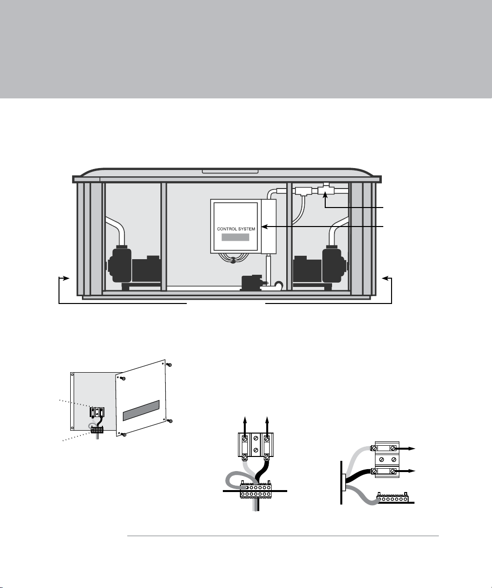
Electrical Tasks After Spa Delivery, Continued
Hot Tub
Control Box
TB1
Terminal
Ground/
Bonding Lug
Note: TB1 terminal location will vary between
models; 3-wire/240 VAC connection illustrated
Figure 4:
Control Box
TB1
Red (L2)
Red
Green
Black (L1)
Black
Figure 5A:
3-Wire/240 VAC Connection
for 880 Altamar, Cameo, Capri,
Majesta, Marin, Maxxus, Optima,
Models.
Hard Wired Connections Only.
External
Power
To spa circuit
TB1
Figure 5B:
3-Wire/240 VAC Connection
for 780 Camden, Certa,
Chelsee, Hamilton, and
680 Burlington, Hartford,
Hawthorne Models.
Hard Wired Connections Only.
Black
(L2)
Black
Red
(L1)
Red
Green
To spa
circuit
External Power
Installing a 3-Wire 240 VAC Connection for 880 Altamar, Cameo, Capri,
Majesta, Marin, Maxxus, Optima Models, 780 Camden, Certa, Chelsee,
Hamilton Models, and 680 Burlington, Hartford and Hawthorne Models
Attach to a
Sundance
Ozone Unit
(Aftermarket
purchase)
Control Box
Power Supply Inlets
Figure 3: Spa equipment compartment
The Control Box for 3-wire, 240 VAC
connection
20
The location of the TB1 terminal may vary
between models.
Continued on next page
Page 23
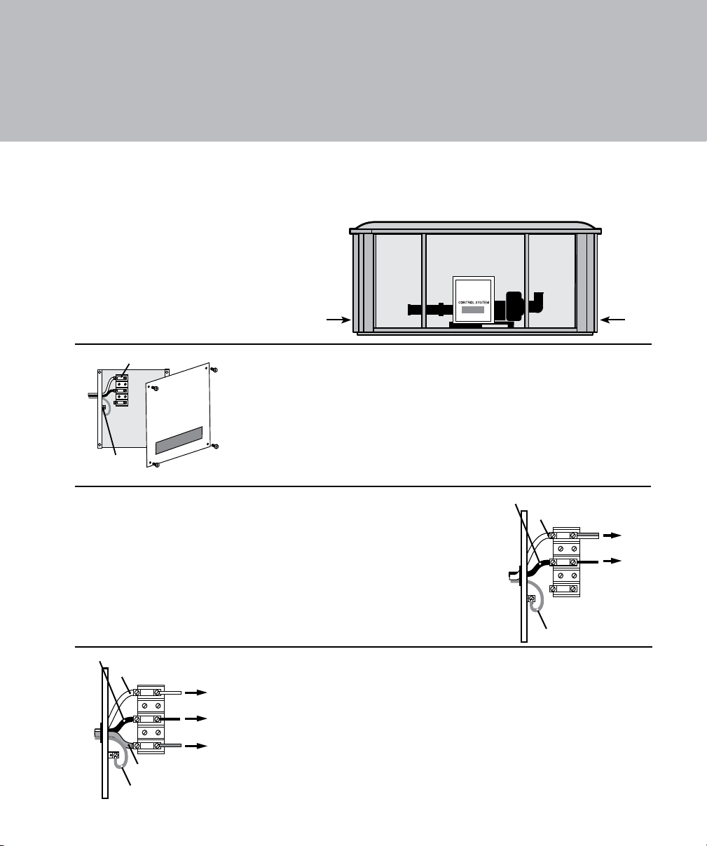
Electrical Tasks After Spa Delivery, Continued
TB1
Terminal
Ground/
Bonding Lug
Note: TB1 terminal location will vary between models
Hot Tub
Control Box
TB1
Green
To spa
circuit
White
(Neutral)
Black (L)
White
Black
Red
Exte rnal Power
TB1
White
(Neutral)
Red (L2)
Green
Black (L1)
To spa
circuit
To spa
circuit
White
Black
Red
Exte rnal Power
Installing a 3-Wire 120 VAC or 4-Wire 120/240 VAC Connection for 780
Dover Models, 680 Denali, Tacoma Models
Figure 6 The Spa Equipment Compartment
Power Supply Inlets
Figure 7 The Control Box for Denali,
Dover, and Tacoma Models
The 3-wire, 120 VAC connection is
illustrated. The location of the TB1 terminal
may vary between models.
Figure 8 Standard 3-wire, 120 VAC
connection for Denali, Dover and Tacoma
models.
Use the supplied GFCI cord for installations
in the USA. Otherwise, hard wire a 3-wire
connection.
Figure 9 Standard 4-wire, 240/120 VAC
connection for Denali, Dover and Tacoma
models. Move red wire to terminal position
#3 as shown. (Hard wired connections only).
21
Page 24

Final Electrical Connections
Now, you can have the final electrical connections made to your spa. Various wiring
diagrams are illustrated on the next few pages. Each spa model has a slightly different
configuration, so use the chart below to find the configuration for your spa.
Configuration # Details
240 VAC Connections for North America 60 Hz:
880 Altamar, Cameo, Capri, Majesta, Marin, Optima, •
1
2
3
Ask your electrician to view the diagrams on the next few pages to ensure all connections are
correct.
Maxxus Models
780 Camden, Certa, Chelsee, Hamilton Models•
680 Burlington, Hartford, Hawthorne Models•
120 VAC Connections for North America 60 Hz:
Denali, Dover, Tacoma Models•
240 VAC Connections for North America 60 Hz
Denali, Dover, Tacoma Models•
Continued on next page
22
Page 25
Red (L2)
Red (L2)
Pigtail
Neutral Bus
Ground
TB2
Black (L1)
Black (L1)
Green
GFCI Sub Panel*
Main Panel*
2-Pole
GFCI
Breaker
Ground/Bonding Lug**
No Load Neutral Wire
Main Panel with Secondary GFCI Shut-Off Box Using a
2-Pole GFCI Breaker with 2-Wire Grounded Connection
(3 Wires to Hot Tub, 2-Hot (L1-L2), 1-Ground)
TB1
White (N)
Green (Ground)
*GFCI Sub Panel commonly
used when recommended GFCI
does not install in Main Panel.
Note: service disconnect not
shown in this diagram.
The control box TB1 terminal
position varies between models.
BR
Hot Tub
Control Box
Red (L2)
Pigtail
Neutral Bus
Ground
TB2
TB1
Black (L1)
Green
Main
Service
Panel
with
GFCI
2-Pole
GFCI
Breaker
Ground/Bonding Lug**
2-Pole Circuit Breaker with 2-Wire Grounded Load Connection
(3 Wires to Hot Tub, 2-Hot (L1-L2), 1-Ground)
White (N)
Black (L1)
Red (L2)
240 VAC
No Load Neutral Wire
Note: service disconnect not
shown in this diagram.
The control box TB1 terminal
position varies between models.
BR
Hot Tub
Control Box
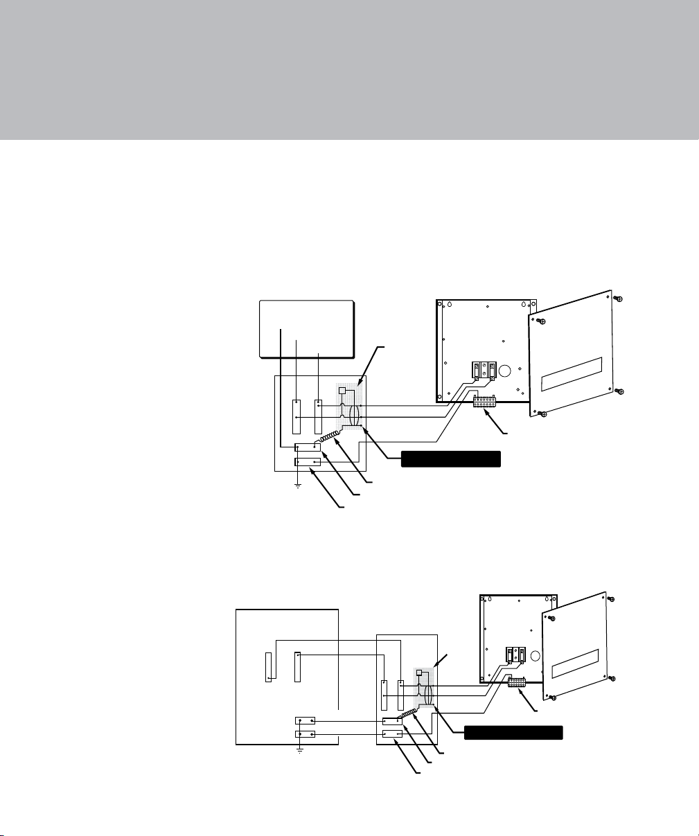
Connection Configuration #1
240 VAC Connections for 880 Altamar, Cameo, Capri, Majesta, Marin, Optima, Maxxus, 780 Camden, Certa, Chelsee, Hamilton Models, 680 Burlington, Hartford, Hawthorne Models (North America 60 Hz)
A pressure sensitive
terminal block (bonding
lug) is attached to the
outside surface of the
load box. This permits the
connection of a bonding
wire between this point
and any metal equipment
chassis, metal water pipe,
or metal conduit within 5
ft (1.5m) of the spa. The
bonding wire must be at
least #8 AWG (8.4 mm
solid copper wire.
²)
23
Page 26
Pigtail
Neutral Bus
Ground
TB2
TB1
Black (L)
White (N)
Green
Main
Service
Panel
with
GFCI
1-Pole
GFCI
Breaker
Ground/Bonding Lug**
1-Pole Circuit Breaker with 3-Wire Grounded Load Connection
(3 Wires to Hot Tub, 1-Hot (L), 1-Neutral (N), 1-Ground)
White (N)
Black (L)
120 VAC
Load Neutral Lug on Breaker
Note: service disconnect not
shown in this diagram.
The control box TB1 terminal
position varies between models.
BW
Hot Tub
Control Box
Black (L)
Black (L)
Pigtail
Neutral Bus
Ground
TB2
Green
GFCI Sub Panel*
Main Panel*
1-Pole
GFCI
Breaker
Ground/Bonding Lug**
Load Neutral Lug on Breaker
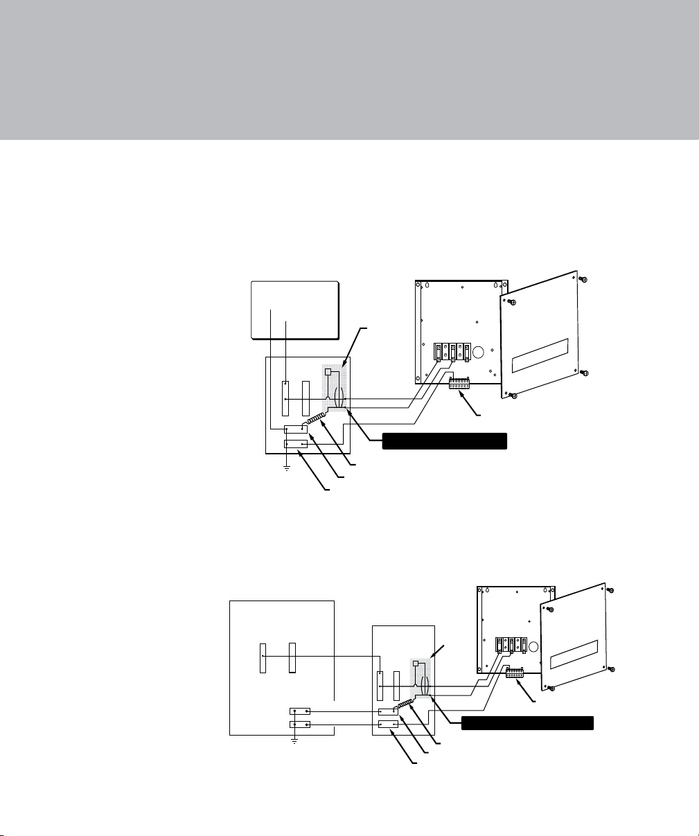
Main Panel with Secondary GFCI Shut-Off Box Using a
1-Pole GFCI Breaker with 3-Wire Grounded Connection
(3 Wires to Hot Tub, 1-Hot (L), 1-Neutral (N), 1-Ground)
White (N)
Green (Ground)
*GFCI Sub Panel commonly
used when recommended GFCI
does not install in Main Panel.
Note: service disconnect not
shown in this diagram.
The control box TB1 terminal
position varies between models.
Hot Tub
Control Box
White (N)
TB1
BW
Connection Configuration #2
120 VAC Connections for Denali, Dover, Tacoma Models (North America 60 Hz)
If the supplied
10 ft GFCI power cord
(US only) cannot reach a
dedicated, grounded wall
outlet, it is necessary to
install a 3-wire,
hard-wired connection.
These diagrams illustrate
that conguration.
For enhanced heater
performance the use of a
4-wire power connection is
necessary.
A pressure sensitive
terminal block (bonding
lug) is attached to the
outside surface of the
load box. This permits the
connection of a bonding
wire between this point
and any metal equipment
chassis, metal water
pipe, or metal conduit
within 5 ft (1.5m) of the
spa. The bonding wire
must be at least a #8
AWG (8.4 mm
copper wire.
24
²) solid
Page 27
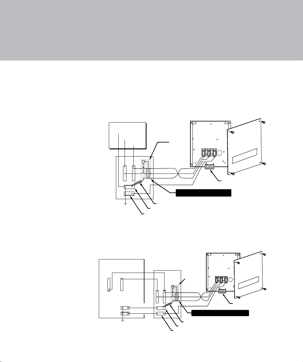
Connection Configuration #3
Red (L2)
Pigtail
Neutral Bus
Ground
TB2
TB1
Black (L1)
White (N)
Green
Main
Service
Panel
with
GFCI
White (N)
Black (L1)
Red (L2)
240 VAC/120 VAC
2-Pole
GFCI
Breaker
Ground/Bonding Lug**
Load Neutral Lug on Breaker
2-Pole Circuit Breaker with 3-Wire Grounded Load Connection
(4 Wires to Hot Tub, 2-Hot (L1-L2), 1-Neutral (N), 1-Ground)
Note: service disconnect not
shown in this diagram.
The control box TB1 terminal
position varies between models.
W B R
Hot Tub
Control Box
Red (L2)
Pigtail
Neutral Bus
Ground
TB2
Black (L1)
GFCI Sub Panel*
Main Panel*
2-Pole
GFCI
Breaker
Ground/Bonding Lug**
Load Neutral Lug on Breaker
Main Panel with Secondary GFCI Shut-Off Box Using a
2-Pole GFCI Breaker with 3-Wire Grounded Connection
(4 Wires to Hot Tub, 2-Hot (L1-L2), 1-Neutral (N), 1-Ground)
White (N)
Green (Ground)
*GFCI Sub Panel commonly
used when recommended GFCI
does not install in Main Panel.
Note: service disconnect not
shown in this diagram.
The control box TB1 terminal
position varies between models.
Red (L2)
TB1
Black (L1)
White (N)
Green
W B R
Hot Tub
Control Box
240 VAC Connections for Denali, Dover, Tacoma Models (North America 60 Hz)
A pressure sensitive
terminal block (bonding
lug) is attached to the
outside surface of the
load box. This permits
the connection of a
bonding wire between
this point and any metal
equipment chassis,
metal water pipe, or
metal conduit within 5 ft
(1.5m) of the spa. The
bonding wire must be at
least #8 AWG (8.4 mm
solid copper wire.
²)
25
Page 28
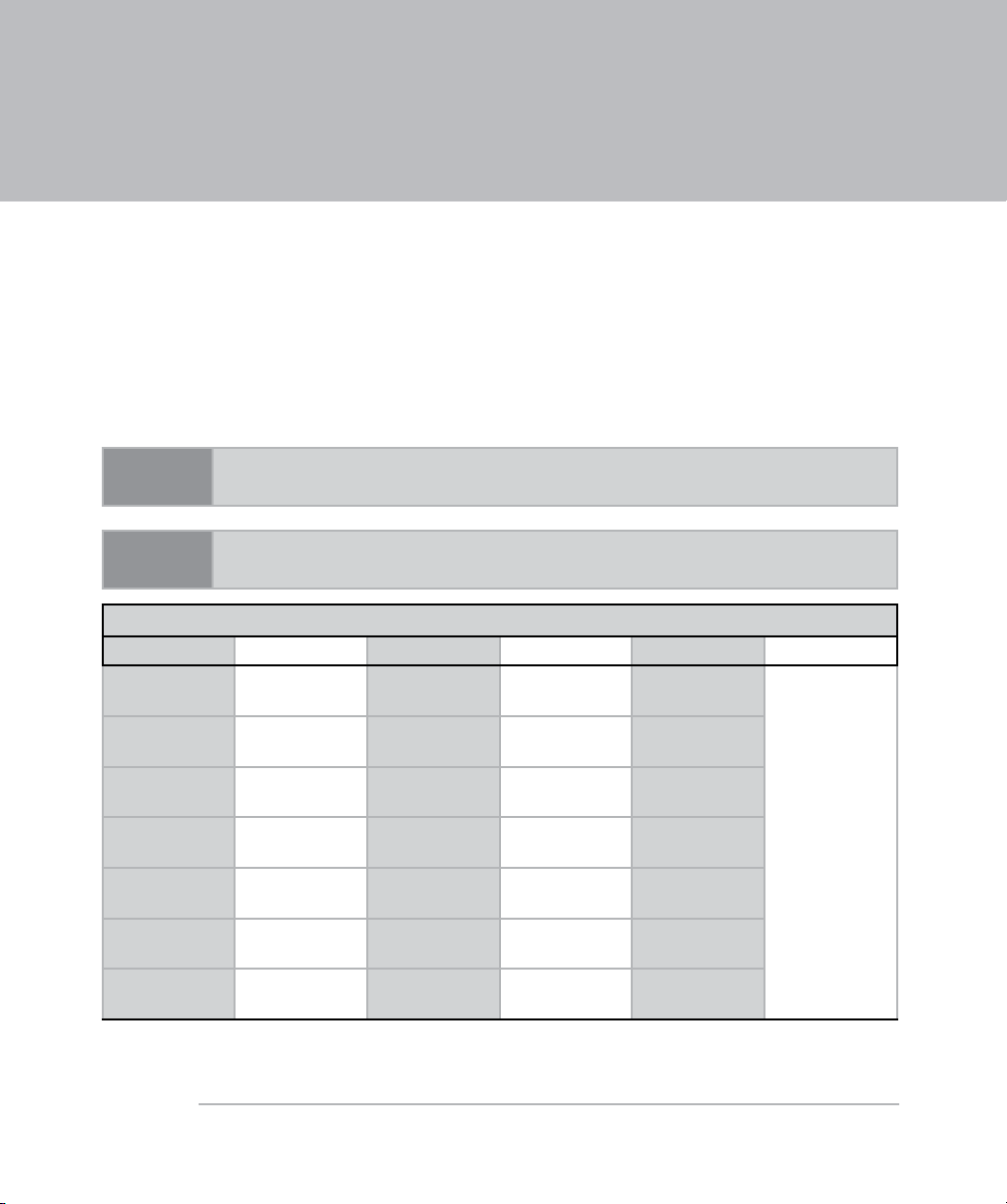
Spa Dimensions and Specifications
Useful Details About the Spa
The tables below provide the spa dimensions and specifications that may be helpful when installing
your spa. These specifications are approximate.
The filled weight specifications vary depending on the height of the spa’s water. The filled weight is
the weight of the spa (empty), plus the weight of the water at its maximum potential capacity (filled
to the point of overflowing). The filled weight specifications do not include the weight of potential
hot tub users who might be inside the hot tub. To ensure proper operation, the spa’s water should
always be above all the jets, and approximately one inch below all the pillows.
NOTE
Always measure your spa before making critical design or delivery
pathway decisions.
NOTE
These specications are subject to change without notice and are for
reference only.
880 Series
Model Width Length Depth Filled Weight Min. Pad Size
Altamar
Cameo
Capri
Majesta
Marin
Maxxus
Optima
81 in.
(206 cm)
89 in.
(226 cm)
69 in.
(175.5 cm)
81 in.
(206 cm)
75 in.
(190.5 cm)
90 in.
(229 cm)
89 in.
(226 cm)
86 in.
(218.5 cm)
89 in.
(226 cm)
82 in.
(208.5 cm)
86 in.
(218.5 cm)
91 in.
(231 cm)
110 in.
(279.5 cm)
89 in.
(226 cm)
37.5 in.
(95.5 cm)
37.5 in.
(95.5 cm)
30.5 in.
(77.5 cm)
37.5 in.
(95.5 cm)
33 in.
(84 cm)
41.5 in.
(105.5 cm)
37.5 in.
(95.5 cm)
4618 lb.
(2095 kg)
4691 lb.
(2128 kg)
3215 lb.
(1458 kg)
4331 lb.
(1965 kg)
4178 lb.
(1895 kg)
6708 lb.
(3043 kg)
5361 lb.
(2432 kg)
4 in.
(102 mm)
26
Continued on next page
Page 29

Useful Details About the Spa, Continued
780 Series
Model Width Length Depth Filled Weight Min. Pad Size
76 in.
Camden
Certa
Chelsee
Dover
Hamilton
Model Width Length Depth Filled Weight Min. Pad Size
Burlington
Denali
Hartford
Hawthorne
Tacoma
(193 cm)
81 in.
(206 cm)
88 in.
(223.5 cm)
69 in.
(175.5 cm)
92 in.
(234 cm)
81 in.
(206 cm)
78.5 in.
(200 cm)
88 in.
(223.5 cm)
92 in.
(234 cm)
68 in.
(173 cm)
83 in.
(211 cm)
86 in.
(218.5 cm)
88 in.
(223.5 cm)
82 in.
(208.5 cm)
92 in.
(234 cm)
680 Series
86 in.
(218.5 cm)
78.5 in.
(200 cm)
88 in.
(223.5 cm)
92 in.
(234 cm)
68 in.
(173 cm)
34 in.
(86.5 cm)
37.5 in.
(95.5 cm)
36 in.
(91.5 cm)
30.5 in.
(77.5 cm)
36 in.
(91.5 cm)
37.5 in.
(95.5 cm)
36 in.
(91.5 cm)
36 in.
(91.5 cm)
36 in.
(91.5 cm)
31 in.
(79 cm)
3476 lb.
(1577 kg)
4477 lb.
(2031 kg)
4711 lb.
(2137 kg)
3124 lb.
(1417 kg)
5440 lb.
(2468 kg)
4249 lb.
(1927 kg)
2987 lb.
(1314 kg)
4697 lb.
(2131 kg)
5353 lb.
(2428 kg)
1946 lb.
(883 kg)
4 in.
(102 mm)
4 in.
(102 mm)
27
Page 30

Page 31

Page 32

www.sundancespas.com
800.899.7727
P/N 6890-558T, Rev. A 06/08
©Sundance Spas, Inc. Pre-delivery Guide, Inc. All rights reserved.
 Loading...