

Page 1
680
Burlington™ | Denali™ | Hartford™ | Hawthorne™ | Tacoma
Owner’s manual
6530-681U Rev. B
™
Page 2

Attention New Spa Owner!
Congratulations on the purchase of your new Sundance® 680 Series
spa! The following is a list of automated functions and maintenance
recommendations for your new spa. Automated functions have been
listed below in an attempt to suppress any operational concerns you may
have during startup and the rst 24 hours of ownership! Maintenance
recommendations are listed in an attempt to stress their importance in
protecting your new spa.
Automated Operations
Approximately two minutes after power is applied to the spa, the rst
ltration/heating cycle turns on pump 1. In Hartford and Hawthorne models,
an automatic ve minute “blow-out” function also activates pump 2 for a
period of ve minutes to ush all lines. Then, after ve minutes, pump 2
turns off and pump 1 continues to operate for the duration of the cycle.
Note: This function only occurs during the rst ltration/heating cycle each
day.
Maintain Healthy Spa Water
Always maintain your spa’s water chemistry within the following parameters
as dened by the Association of Pool And Spa Professionals/USA:
pH 7.4-7.6
Free Chlorine 3.0-4.0 ppm
Free Bromine 2.0-4.0 ppm
Total Alkalinity 100-120 ppm
Calcium Hardness 150-250 ppm
Always maintain your spa lter as outlined below to ensure healthy spa
water. Refer to pages 34-35 for additional information.
Required Filter Maintenance
Your new spa is equipped with an advanced water ltration system that
provides unsurpassed water quality! To ensure maximum water quality at all
times, you should clean and reuse both lter cartridges every month or as
needed. See page 30 for detailed lter cleaning/replacement instructions.
Required Water Maintenance
You should replace the spa’s water every 3 months. The frequency
depends on a number of variables including frequency of use, number of
users, and attention paid to water quality maintenance. You will know it
is time for a change when you cannot control sudsing and/or you can no
longer get the normal feel or sparkle to the water, even though the key
water balance measurements are all within the proper parameters. See
pages 34-35 for additional information.
© 2009 by Sundance Spas, Inc. All Rights Reserved
Page 3

680 SERIES
Table of Contents
1.0 Important Spa Owner Information ............................................ 1
2.0 FCC Notice .................................................................................. 1
3.0 Important Safety Instructions ................................................... 2
3.1 Important CSA Safety Instructions (Canada only) ....................... 4
3.2 Hyperthermia ............................................................................... 5
3.3 Cautions ...................................................................................... 6
3.4 General Electrical Safety Instructions .......................................... 6
4.0 Choosing A Location ................................................................. 8
4.1 Outdoor Location ......................................................................... 8
4.2 Indoor Location ............................................................................ 9
5.0 Power Requirements ............................................................... 10
5.1 North American 60 Hz Power Options ....................................... 10
5.2 Export 50 Hz Power Options ..................................................... 12
6.0 Electrical Wiring Instructions ................................................. 13
7.0 Spa Fill Up Procedure .............................................................. 16
8.0 Control Functions .................................................................... 21
8.1 Control Panel ............................................................................. 21
8.2 General Spa Features And Controls .......................................... 22
9.0 Operating Instructions ............................................................ 23
9.1 Setting Water Temperature ....................................................... 23
9.2 Activate Pumps .......................................................................... 23
9.3 SunGlow™ Light Operation (Denali and Tacoma Models) ........ 24
9.4 Standard Light Operation (Burlington, Hartford
and Hawthorne Models) ........................................................... 24
9.5 Optional Multi-Colored LED Light System Operation
(Burlington, Hartford and Hawthorne Models) ........................... 24
9.6 Adjusting Individual Jet Flow ..................................................... 25
9.7 Selecting Desired Massage Action ........................................... 26
9.8 Air Controls ................................................................................ 26
9.9 Optional Audio System .............................................................. 26
Page 4

680 SERIES
10.0 Automatic Filtration Cycles .................................................... 27
10.1 Standard Filtration/Heating Modes For Models
Without Circulation Pump Option .............................................. 27
10.2 Standard Filtration/Heating Modes For Models
With Circulation Pump Option ................................................... 27
10.3 Economy Filtration/Heating Modes (F4-F6) ............................... 27
10.4 Lock Modes (L1-L2) ................................................................... 27
10.5 Selecting The Filtration/Heating Mode ...................................... 28
10.6 Filtration Modes for Spas Without Circulation Pump Option ..... 28
10.7 Filtration Modes for Spas With Circulation Pump Option .......... 29
11.0 Spa Maintenance...................................................................... 30
11.1 Cleaning The Filter .................................................................... 30
11.2 Draining and Relling ................................................................ 31
11.3 Pillow Care (All Models Except Denali) ..................................... 32
11.4 Cleaning The Spa Interior .......................................................... 33
11.5 Maintaining The Cover .............................................................. 33
11.6 Maintaining The Synthetic Cabinet ............................................ 33
11.7 Winterizing ................................................................................. 33
11.8 Restarting Your Spa in Cold Weather ........................................ 34
12.0 Water Quality Maintenance ..................................................... 34
12.1 pH Control ................................................................................. 35
12.2 Sanitizing ................................................................................... 35
12.3 CD Ozone Water Maintenance System ..................................... 35
13.0 Error Conditions/Error Messages .......................................... 36
13.1 Summer Logic (Spas With Circulation Pump Option) ................ 36
13.2 Panel displays SN1 ................................................................... 36
13.3 Panel displays SN2 ................................................................... 36
13.4 Panel Flashes FL1 or FL2 (Spas Without
Circulation Pump Option) .......................................................... 36
13.5 Panel Flashes FL1 or FL2 (Spas With
Circulation Pump Option) .......................................................... 37
13.6 Panel displays COL ................................................................... 37
13.7 Panel Displays ICE .................................................................... 37
13.8 Panel Displays OH .................................................................... 37
13.9 Panel displays - - - .................................................................... 38
14.0 Troubleshooting Procedures .................................................. 38
14.1 None of the Components Operate (e.g. Pump, Light) .............. 38
14.2 Pump Does Not Operate but Light Does ................................... 38
14.3 Poor Jet Action .......................................................................... 39
Page 5

680 SERIES
14.4 Water is Too Hot ........................................................................ 39
14.5 No Heat ..................................................................................... 39
15.0 North American Denali/Tacoma Convertible
Circuit Diagram (60 Hz) ........................................................... 40
16.0 North American Burlington Models (60 Hz) ........................... 41
17.0 North American Hartford and Hawthorne Models (60 Hz) .... 42
18.0 Export Denali/Tacoma Circuit Diagram (50 Hz) ..................... 43
19.0 Export Burlington Circuit Diagram (50 Hz) ............................ 44
20.0 Export Hartford and Hawthorne Circuit Diagram (50 Hz) ..... 45
21.0 Optional SunSoundTM Stereo Receiver Functions
(Burlington, Hartford and Hawthorne Models Only) ............. 46
21.1 Optional SunSoundTM Audio Receiver Specications ................ 51
Page 6

Page 7

680 SERIES
1.0 Important Spa Owner Information
Your Sundance® 680 Series spa is constructed to the highest standards
and is capable of providing many years of trouble-free use. However,
because heat retentive materials are utilized to insulate the spa for
efcient operation, an uncovered spa surface and wall ttings directly
exposed to sunlight and high temperatures for an extended period
are subject to permanent damage or discoloration. Damage caused
by exposing the spa to this abuse is not covered under warranty.
We recommend that you always keep the spa full of water when it is
exposed to direct sunlight and that you keep the Sundance premium
insulating cover in place at all times when the spa is not in use. Read
and carefully follow the requirements for your spa’s support base found
in Section 4.0 titled, “Choosing a Location” (page 8).
Sundance constantly strives to offer the finest spas available,
therefore modifications and enhancements may be made which
affect the specifications, illustrations and/or instructions contained
herein.
2.0 FCC Notice
This equipment has been tested and found to comply with the limits for
a Class B Digital Device, pursuant to Part 15 of the FCC Rules. These
limits are designed to provide reasonable protection against harmful
interference in a residential installation. This equipment generates, uses
and can radiate radio frequency energy and, if not installed and used
in accordance with the instructions, may cause harmful interference to
radio communications. However, there is no guarantee that interference
will not occur in a particular installation. If this equipment does cause
harmful interference to radio or television reception, which can be
determined by turning the equipment off and on, the user is encouraged
to try to correct the interference by one or more of the following
measures:
1. Rearrange or relocate the receiving antenna.
2. Increase the separation between the equipment and receiver
3. Connect the equipment into an outlet on a circuit different from the
circuit connected.
4. Consult the dealer or an experienced radio/TV technician for help.
Changes or modications not expressly approved by the party
responsible for FCC compliance could void the user’s authority to
operate this equipment.
Page 1
Page 8

680 SERIES
3.0 Important Safety Instructions
READ AND FOLLOW ALL INSTRUCTIONS CAREFULLY!
When installing and using this electrical equipment, basic safety
precautions should always be followed, including:
1. WARNING: To reduce the risk of injury, do not permit children to use
this product unless they are closely supervised at all times.
2. WARNING: A grounding wire connector is provided on this unit to
connect a minimum No. 8 AWG (8.4 mm²) solid copper conductor
between this unit and any metal equipment, metal enclosures of
electrical equipment, metal water pipe, or conduit within 5 feet (1.5m)
of the unit.
3. DANGER: Risk of Accidental Drowning. Extreme caution must
be exercised to prevent unauthorized access by children. To avoid
accidents, ensure that children cannot use this spa unless they are
supervised at all times.
4. DANGER: Risk of Severe Injury or Drowning!
The suction ttings in this spa are sized to match the specic water
ow created by the pump. If it is necessary to replace the suction
ttings or the pump, be sure that the ow rates are compatible.
Never operate or use the spa if the lter, lter lid, or skimmer •
assembly are broken or any part of the skimmer assembly is
missing. Please contact your dealer or nearest service center for
service.
Never replace a suction tting with one rated less than the ow •
rate marked on the original suction tting. Using improper suction
ttings can create a body or hair suction entrapment hazard that
may lead to drowning or near drowning.
Never use the spa unless all suction guards, lter, lter lid, or •
skimmer assembly are installed to prevent body and/or hair
entrapment.
Keep hair, loose articles of clothing or hanging jewelry away from •
suction ttings, rotating jets or other moving components to avoid
entrapment that could lead to drowning or near drowning.
5. DANGER: Risk of Electric Shock. Install at least 5 feet (1.5m) from
all metal surfaces. As an alternative, a spa may be installed within
5 feet (1.5m) of metal surfaces if each metal surface is permanently
connected (bonded) by a minimum No. 8 AWG (8.4 mm²) solid
copper conductor attached to the wire connector on the grounding
lug, inside the equipment compartment on the equipment box.
6. DANGER: Risk of Electric Shock. Do not permit any electrical
appliance, such as a light, telephone, radio, television, etc. within
5 feet (1.5m) of a spa, unless such appliances are built-in by the
manufacturer.
Page 2
Page 9

680 SERIES
7. ELECTRICAL SUPPLY: The electrical supply for this product
must include a suitably rated switch or circuit breaker to open all
ungrounded supply conductors to comply with Section 422-20 of the
National Electrical Code/USA, ANSI/NFPA 70. The disconnect must
be readily accessible and visible to the spa occupant but installed at
least 5 feet (1.5m) from the spa water.
8. WARNING: To Reduce the Risk of Injury:
9. The water in a spa should never exceed 104°F (40°C). Water
temperatures between 100°F (38°C) and 104°F (40°C) are
considered safe for a healthy adult. Lower water temperatures are
recommended for young children and when spa use exceeds 10
minutes.
10. Since excessive water temperatures have a high potential for
causing fetal damage during the early months of pregnancy,
pregnant or possibly pregnant women should limit spa water
temperatures to 100°F (38°C). If pregnant, please consult your
physician before using a spa.
11. Before entering the spa, the user should measure the water
temperature with an accurate thermometer since the tolerance of
water temperature-regulating devices may vary as much as +/- 5°F
(2°C).
12. The use of alcohol, drugs, or medication before or during spa use
may lead to unconsciousness with the possibility of drowning.
13. Persons suffering from obesity or a medical history of heart
disease, low or high blood pressure, circulatory system problems,
diabetes, infectious diseases or immune deciency syndromes
should consult a physician before using a spa. If you experience
breathing difculties in association with using or operating your spa,
discontinue use and consult your physician.
14. Persons using medication should consult a physician before using
a spa since some medication may induce drowsiness, while other
medication may affect heart rate, blood pressure, and circulation.
15. Always shower before and after using your spa. To reduce the
possibility of contracting a waterborne illness, always maintain
water chemistry within the parameters listed on the inside cover of
this manual. If you or other bathers experience such a condition,
discontinue use and seek medical attention.
Page 3
Page 10

680 SERIES
3.1 Important CSA Safety Instructions (Canada only)
When using this electrical equipment, basic safety precautions should
always be followed, including the following:
1. READ AND FOLLOW ALL INSTRUCTIONS.
2. A green colored terminal or a terminal marked G, Gr, Ground,
Grounding or the symbol* is located inside the supply terminal box
or compartment. To reduce the risk of electric shock, this terminal
must be connected to the grounding means provided in the electric
supply service panel with a continuous copper wire equivalent
in size to the circuit conductors that supply this equipment (*IEC
Publication 417, Symbol 5019).
3. At least two lugs marked “Bonding Lugs” are provided on the
external surface or on the inside of the supply terminal box/
compartment. To reduce the risk of electric shock, connect the local
common bonding grid in the area of the spa to these terminals with
an insulated or bare copper conductor not smaller than No. 6 AWG
(10 mm²).
4. All eld-installed metal components such as rails, ladders, drains or
other similar hardware within 10 feet (3m) of the spa shall be bonded
to the equipment grounding buss with copper conductors not smaller
than No. 6 AWG (10 mm²).
5. SAVE THESE INSTRUCTIONS.
WARNING: Children should not use spas without adult supervision.
WARNING: Do not use spas unless all suction guards are installed to
prevent body and hair entrapment.
WARNING: People with infectious diseases should not use a spa.
WARNING: To avoid injury, exercise care when entering or exiting the
spa.
WARNING: Do not use drugs or alcohol before or during the use of a
spa to avoid unconsciousness and possible drowning.
WARNING: Pregnant or possibly pregnant women should consult a
physician before using a spa.
Page 4
Page 11

680 SERIES
WARNING: Water temperature in excess of 40°C (104°F) may be
injurious to your health.
WARNING: Before entering the spa, measure the water temperature
with an accurate thermometer.
WARNING: Do not use a spa immediately following strenuous exercise.
WARNING: Prolonged immersion in a spa may be injurious to your
health.
WARNING: Do not permit electric appliances (such as lights, radios,
telephones, televisions, etc.) within 5 feet (1.5m) of this spa unless
factory installed.
CAUTION: Maintain water chemistry in accordance with manufacturer’s
instructions.
WARNING: The use of alcohol or drugs can greatly increase the risk of
fatal hyperthermia in spas.
3.2 Hyperthermia
Prolonged immersion in hot water may induce hyperthermia. A
description of the causes, symptoms, and effects of hyperthermia are as
follows:
Hyperthermia occurs when the internal temperature of the body reaches
a level several degrees above the normal body temperature of 98.6°F
(37°C). The symptoms of hyperthermia include drowsiness, lethargy,
and an increase in the internal temperature of the body. The effects of
hyperthermia include:
• Unawareness of impending hazard;
• Failure to perceive heat;
• Failure to recognize the need to exit spa;
• Physical inability to exit spa;
• Fetal damage in pregnant women; and
• Unconsciousness and danger of drowning.
Page 5
Page 12

680 SERIES
3.3 Cautions
1. Persons suffering from heart disease, diabetes, high or low blood
pressure, and any condition requiring medical treatment, pregnant
women, the elderly, or infants should consult with a physician before
using a spa.
2. The Consumer Products Safety Commission/USA has stated that
the water temperature in a spa should not exceed 104°F (40°C).
Immersion in water in excess of 104°F (40°C) can be hazardous to
your health.
3. Observe a reasonable time limit when using the spa. Long
exposures at higher temperatures can cause high body temperature.
Symptoms may include dizziness, nausea, fainting, drowsiness, and
reduced awareness. These effects could possibly result in drowning.
4. Do not use the spa under the inuence of alcohol, narcotics, or other
drugs. Use of the spa under these conditions may lead to serious
consequences.
5. Always test the spa water temperature before entering the spa.
Enter and exit the spa slowly. Wet surfaces can be very slippery.
6. Never bring any electrical appliances into or near the spa. Never
operate any electrical appliances from inside the spa or when you
are wet unless such appliances are built-in by the manufacturer.
7. Proper chemical maintenance of spa water is necessary to maintain
safe water and prevent possible damage to spa components.
8. Use the straps and clip tie downs to secure the cover when not in
use. This will help to discourage unsupervised children from entering
the spa and keep the spa cover secure in high-wind conditions.
There is no representation that the cover, clip tie-downs, or actual
locks will prevent access to the spa.
9. This spa is not intended nor designed to be used in a commercial or
public application. The spa buyer shall determine whether there are
any code restrictions on the use or installation of this spa since local
code requirements vary from one locality to another.
3.4 General Electrical Safety Instructions
®
Your new Sundance
spa is equipped with a “state-of-the-art” equipment
system. It contains the most advanced safety and self-protective
equipment in the industry. Nonetheless, this spa must be installed
properly to ensure dependable usage. Please contact your local
Sundance dealer or local building department should you have any
questions regarding your installation.
Page 6
Page 13

680 SERIES
Proper grounding is extremely important. Sundance spas are equipped
with a current collector system. A pressure wire connector is provided
on the surface of the control box, located outside the equipment door
(Figure B, page 15) to permit connection of a bonding wire between
this point and any ground metal equipment, metal water pipe or conduit
within 5 feet (1.5m) of the spa, or copper clad grounding rod buried
within 5 feet (1.5m) of the spa. Bonding wire must be at least No. 8 AWG
(8.4 mm²) solid copper wire. This is a most important safety assurance
feature.
Before installing your spa, check with your local building department to
insure installation conforms to local building codes.
120/240 Volt Denali And Tacoma Convertible Models
A spa connected to a 120 VAC electrical service must be located close
enough to a grounded, grounding-type electrical outlet so that the
included 10 foot (3m) power cord can be plugged directly into it. DO
NOT USE AN EXTENSION CORD as this could cause damage to the
spa’s equipment due to insufcient voltage. The power supplied to this
spa must be a dedicated circuit with no other appliances or lights sharing
the power provided by the circuit.
Hot Tub Safety Literature
To ensure you have a safe and enjoyable hot tub experience,
learn all you can about hot tub safety and emergency procedures.
Especially useful are the brochures listed below.
• Children Aren’t Waterproof
• Pool and Spa Emergency Procedures For Infants and
Children
• Layers of Protection
• The Sensible Way to Enjoy Your Spa or Hot Tub
The Association of Pool and Spa Professionals publishes these
brochures. You can acquire a brochure in one of the ways in the list
below.
• Ask your hot tub dealer (they may have copies)
• Go to http://apsp.org
• Conduct your own search on the internet
• Write to the following address:
The Association of Pool and Spa Professionals
2111 Eisenhower Avenue
Alexandria VA 22314
703.838.0083
Page 7
Page 14

680 SERIES
4.0 Choosing A Location
IMPORTANT: Because of the combined weight of the spa, water
and users, it is extremely important that the base upon which the
spa rests be smooth, at, level and capable of uniformly supporting
this weight, without shifting or settling, for the entire time the spa
is in place. If the spa is placed on a surface which does not meet
these requirements, damage to the skirt and/or the spa shell
may result. Damage caused by improper support is not covered
under warranty. It is the responsibility of the spa owner to assure
the integrity of the support over time. We recommend a poured,
reinforced concrete slab with a minimum thickness of 4 inches
(10 cm). Wood decking is also acceptable provided it is
constructed so that it meets the requirements outlined above.
The spa must be installed in such a manner as to provide drainage away
from it. Placing the spa in a depression without provisions for proper
drainage could allow rain, overow and other casual water to ood the
equipment and create a wet condition in which it would sit in. For spas
which will be recessed into a oor or deck, install so as to permit access
to the equipment, either from above or below, for servicing. Make certain
that there are no obstructions which would prevent removal of all side
cabinet panels and access to the jets components, especially on the
side with the equipment bay.
4.1 Outdoor Location
In selecting the ideal outdoor location for your spa, we suggest that you
take into consideration the following:
• The proximity to changing area and shelter (especially in regions
subject to cold weather).
• The pathway to and from your spa (this should be free of debris
so that dirt and leaves are not easily tracked into the spa).
• The closeness to trees and shrubbery (remember that leaves
and birds could create extra work in keeping the spa clean).
• A sheltered environment (less wind and weather exposure can
result in lowered operation and maintenance costs).
• The overall enhancement of your environment. It is preferable
not to place the spa under an unguttered roof overhang since
run-off water will shorten the life expectancy of the spa cover.
Page 8
Page 15

680 SERIES
4.2 Indoor Location
For indoor installations many factors need to be considered before
installing a spa indoors:
• PROPERFOUNDATION: Consult a Structural Engineer when
considering a foundation that will adequately support the spa
the entire time it is in place. Proper support is critical especially
if the spa is to rest on a second story or higher. For spas that
are to rest on balconies, roofs or other platforms not specically
tied into the main structural support, you should consult a
professional Structural Engineer with experience in this type of
application.
• PROPERDRAINAGE. It is extremely important to have in place
measures to sufciently handle excessive water spillage. Be sure
the ooring in which the spa rests on has adequate drainage and
can handle draining of the entire contents of the spa. Be sure to
make provisions for ceilings or any other structures that may be
below the spas installation. Areas around your spa can become
wet or moist so all ooring and subsequent furniture, walls and
adjacent structures should be able to withstand or resist water
and moisture.
• PROPERVENTILATION. Proper ventilation should be discussed
with an Engineer or authority competent enough to understand
the necessary provisions needed to vent moist or heated air and
air associated with chemical odors outdoors. When the spa is
in use considerable amounts of moisture will escape potentially
causing mold and mildew, over time this can damage certain
surfaces and or surroundings.
• SUFFICIENTACCESS. In the unlikely event that you should
ever need to access or gain entry to any portion of the spa for
servicing, it is highly recommended that you plan your indoor
installation to provide full access to the entire spa.
• WARRANTY. Damage caused by not following these guidelines
or any improper installation not in accordance with local codes
or authorities is not covered under the spas warranty. Please
consult your local state or city building ordinances.
WARNING: In addition to maintenance of lters and water
chemistry, proper ventilation is recommended to reduce the
!
risk of exposure to viruses and bacteria that could be present
in the air or water. Consult a licensed architect or building
contractor to determine your specic needs if installing your
spa indoors.
Page 9
Page 16

680 SERIES
5.0 Power Requirements
Sundance® spas are designed to provide optimum performance and
exibility of use when connected to the maximum electrical service listed
on pages 10-12. If you prefer, your dealer can perform a minor circuit
board modication to allow your spa to accept an electrical service other
than the factory setting.
Note: Refer to pages 40-45 for circuit board conguration details or
contact your authorized Sundance dealer.
5.1 North American 60 Hz Power Options
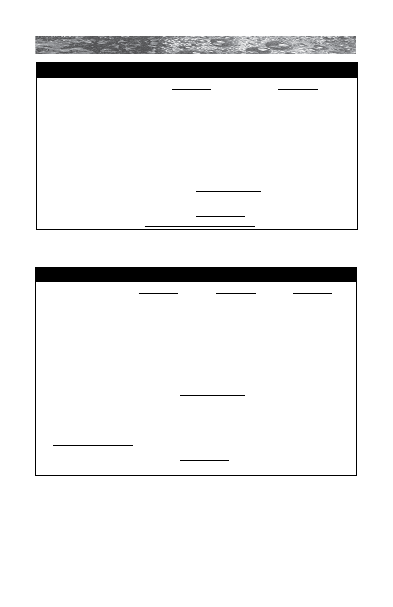
North American Denali/Tacoma 1-Pump Convertible Models (60 Hz)
120V/15A* 240V/30A* 240V/40A**
Voltage: 120 VAC 240 VAC 240 VAC
# of Wires: 3 (15A GFCI Cord - 4 (Hard 4 (Hard
US Models Only*) Wired Only) Wired Only)
Frequency: 60 Hz 60 Hz 60 Hz
Current Draw: 12A 21A 30A
Circuit Breaker: 15A, 1-Pole 30A, 2-Pole 40A, 2-Pole
CAUTION (For 4-wire, 240 VAC Heater Operation): Move the red wire on the
main terminal strip (TB1) from position #1 to position #3. Make certain wires
are connected exactly as shown in Figure D (page 15) before applying power.
Failure to do so will result in damage to the circuit board and/or related compo-
nents and void the manufacturer’s warranty.
* In the 15A/30A configuration, the heater will not operate at the same
time as the high-speed jets pump. The factory setting is 120V/15A.
Note: all Canadian spas must be hard wired (120 VAC or 240 VAC)
per CSA Canadian standards (page 4).
** If the spa is to be operated on 40A service, remove the jumper JP1 #1-2
on the circuit board to allow the heater to operate at the same time as the
high-speed jets pump (page 40).
Page 10
Page 17
680 SERIES
North American Burlington 1-Pump Models (60 Hz)
240V/40A* 240V/50A**
Voltage: 240 VAC 240 VAC
# of Wires: 3 3
Frequency: 60 Hz 60 Hz
Current Draw: 26A 36A
Circuit Breaker: 40A, 2-Pole 50A, 2-Pole
* In the 40A configuration, the heater will not operate while the jets pump is
running in high speed.
** In the 50A configuration, the heater will operate while the jets pump is
running in high speed. This is the factory setting.
North American Hartford and Hawthorne 2-Pump Models (60 Hz)
240V/40A* 240V/50A** 240V/60A***
Voltage: 240 VAC 240 VAC 240 VAC
# of Wires: 3 3 3
Frequency: 60 Hz 60 Hz 60 Hz
Current Draw: 26A 36A 45A
Circuit Breaker: 40A, 2-Pole 50A, 2-Pole 60A, 2-Pole
* In 40A configuration, the heater will not operate while either jets pump is
running in high speed. Note: pump 2 runs only in high speed.
** In 50A configuration, the heater will not operate while both jets pumps are
running in high speed. Note: pump 2 runs only in high speed. This is
the factory setting.
*** In 60A configuration, the heater will operate while both jets pumps are
running in high speed. Note: pump 2 runs only in high speed.
Page 11
Page 18
680 SERIES
5.2 Export 50 Hz Power Options
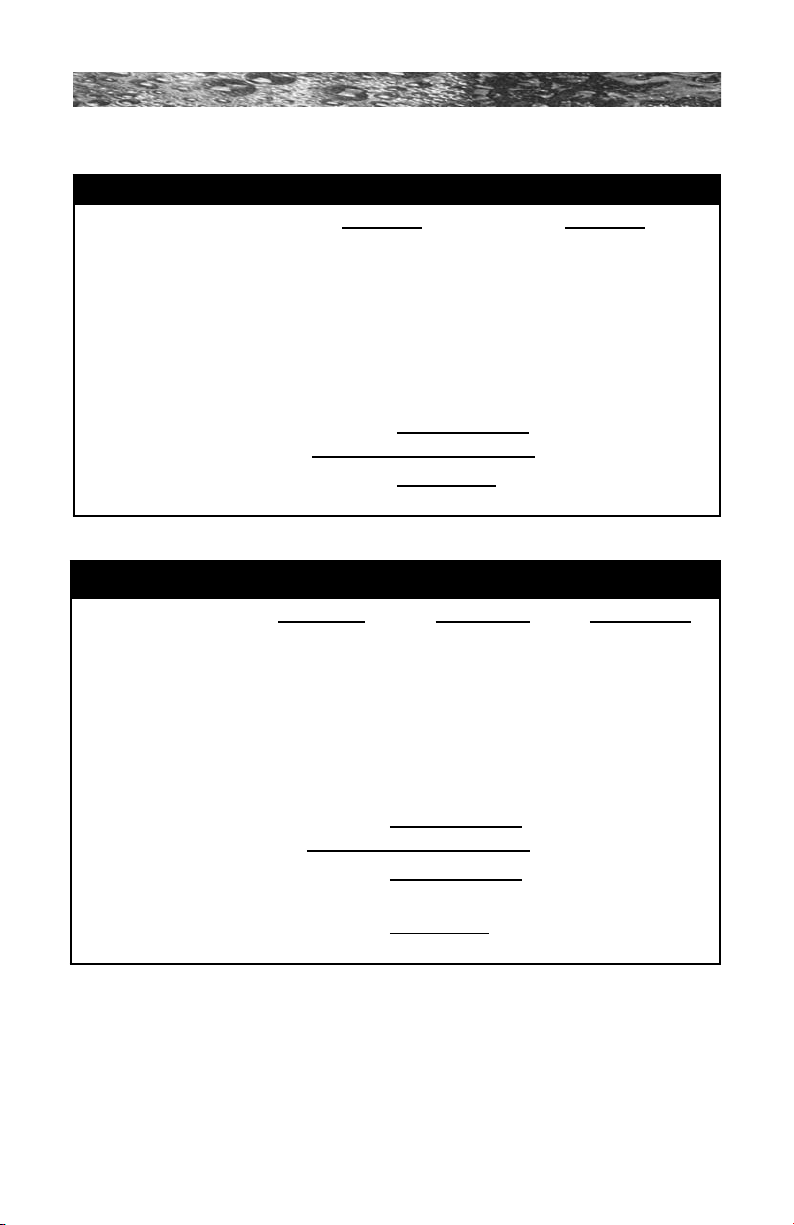
Export Burlington, Denali and Tacoma 1-Pump Models (50 Hz)
230V/20A* 230V/30A**
Voltage: 230 VAC 230 VAC
# of Wires: 3 3
Frequency: 50 Hz 50 Hz
Current Draw: 15A 21A
Circuit Breaker: 20A 30A
* In the 20A configuration, the heater will not operate while the jets pump
is running in high speed. This is the factory setting.
** In the 30A configuration, the heater will operate while the jets pump is
running in high speed.
Export Hartford and Hawthorne 2-Pump Models (50 Hz)
230V/20A* 230V/30A** 230V/40A***
Voltage: 230 VAC 230 VAC 230 VAC
# of Wires: 3 3 3
Frequency: 50 Hz 50 Hz 50 Hz
Current Draw: 15A 23A 29A
Circuit Breaker: 20A 30A 40A
* In the 20A configuration, the heater will not operate while either jets pump
is running in high speed. This is the factory setting.
** In the 30A configuration, the heater will not operate while both jets pumps
are running in high speed.
*** In the 40A configuration, the heater will operate while both jets pumps are
running in high speed.
Page 12
Page 19

680 SERIES
6.0 Electrical Wiring Instructions
IMPORTANT NOTICE: The electrical wiring of this spa must meet
the requirements of the National Electrical Code/USA (NEC) and any
applicable state or local codes. The electrical circuit must be installed
by a qualied electrician and approved by a local building/electrical
inspection authority.
1. Convertible 120/240V Denali/Tacoma Models Only:
• 120V “Plug-in” Operation: This spa must operate on the
supplied 10 foot (3m) 120V GFCI cord at its original length
or must be hard-wired for longer runs. NEVER USE AN
EXTENSION CORD FOR ANY REASON!
• Convertible 120/240V Heater Operation: The included 120V
GFCI cord must be discarded for 240V heater operation.
This spa must be hard-wired. Supplying power to either
conguration above which is not in accordance with these
instructions will void both the independent testing agency
listing and the manufacturer’s warranty.
2. Dedicated 240V Burlington, Hartford and Hawthorne
Models:
This spa must be permanently connected (hard-wired) to the
power supply. No plug-in connections or extension cords are to
be used in conjunction with the operation of this spa. Supplying
power to the spa which is not in accordance with these
instructions will void both the independent testing agency listing
and the manufacturer’s warranty.
3. The power supplied to this spa must be a dedicated circuit with
no other appliances or lights sharing the power provided by the
circuit.
4. To determine the current, voltage and wire size required, refer
to Section 5.0 “Power Requirements” (pages 10-12).
• Wire size must be appropriate per NEC and/or local codes.
• We recommend type THHN wire.
• All wiring must be copper to ensure proper connections. Do
not use aluminum wire.
• When using wire larger than #6 (10 mm²), add a junction
box near the spa and reduce to short lengths of #8
(8.4 mm²) wire to connect to the spa.
Page 13
Page 20
680 SERIES
7
8
36
2
5 5
1
4
9
5. The electrical supply for this product must include a suitably rated
switch or circuit breaker to open all ungrounded supply conductors
to comply with Section 422-20 of the National Electrical Code/USA,
ANSI/NFPA 70. The disconnecting means must be readily accessible
to the spa’s occupant but installed at least 5 feet (1.5m) from spa
water.
6. The electrical circuit supplied for the spa must include a suitable
ground fault circuit interrupter (GFCI) as required by NEC Article
680-42.
7. To gain access to the spa’s power terminal block, remove the screws
securing the cabinet panel on the side of the spa under the control
panel. Then remove the four control box door screws and door
(Figure A-B, pages 14-15).
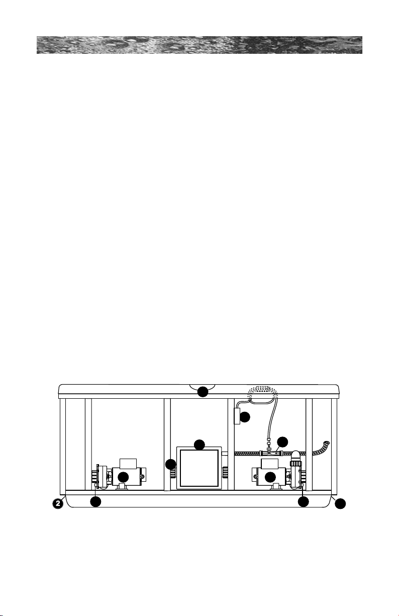
8. Select the power supply inlet you want to use (Figure A, page 14).
Feed power cable to control box, then install it through the large
opening provided in the bottom side of the box.
9. Connect wires, color to color, on terminal blocks TB1 and TB3
(Figures C-F, page 15). TIGHTEN SECURELY! All wires must be
hooked up securely or damage could result.
10. Install control box door and screws and reinstall the cabinet side
panels.
Figure A
Equipment Area
Note: Pump locations vary by model
1. Control Box
2. Power Supply Inlet(s)
3. 2-Speed Pump #1
4. Heater
5. Pump Drain Plugs
6. 1-Speed Pump #2
7. Optional CD Ozonator (Purchased
separately on North American models;
standard equipment on export models
8. Ozone Injector
9. Control Panel
Page 14
Page 21
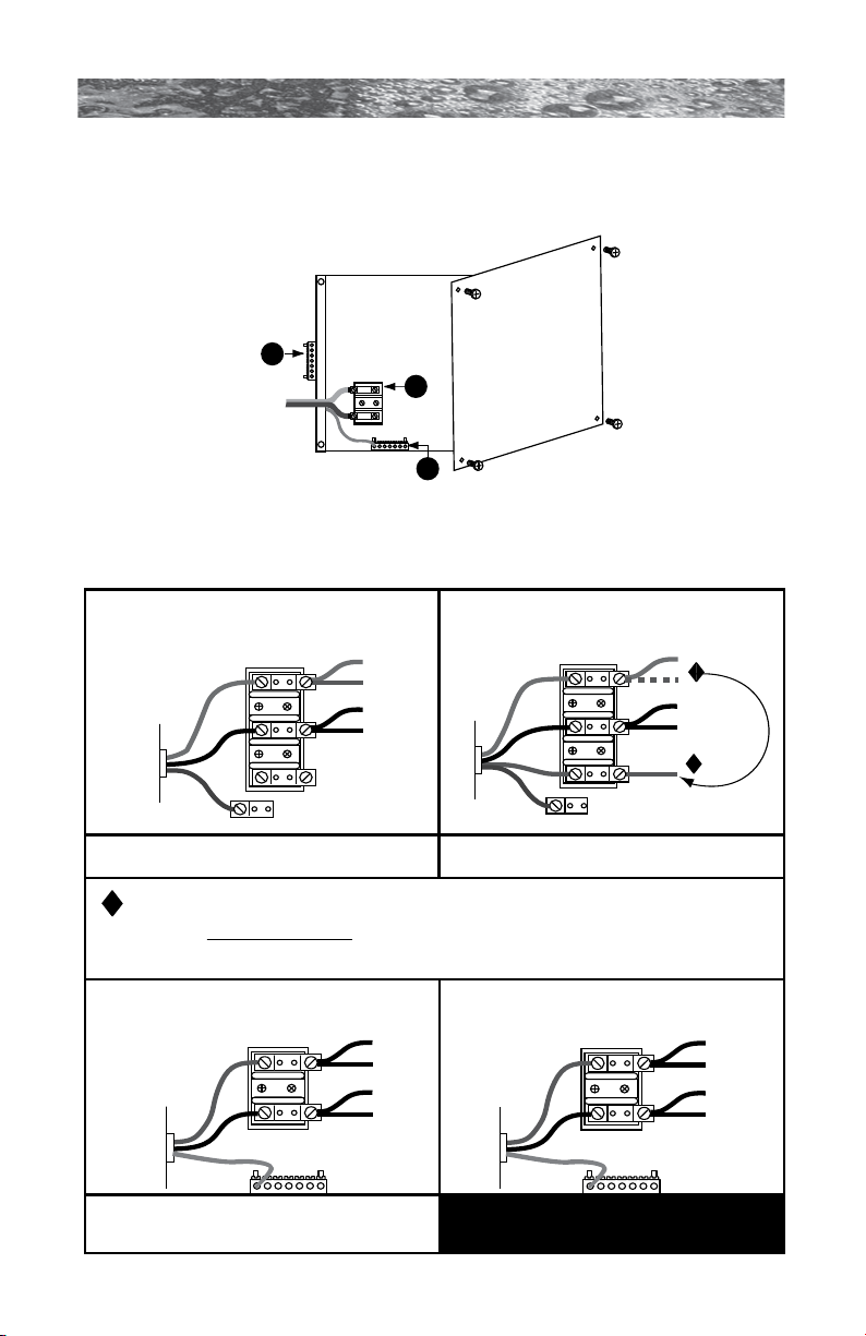
Figure B
TB1
3
2
1
BLUE
BLUE
BROWN
BROWN
1
2
North American Burlington, Hartford
and Hawthorne Models:
240 VAC, 3-Wire Connection (60 Hz)
Figure F
TB1
All Export Models:
230 VAC, 3-Wire (50 Hz)
to Circuit
Board
BLK
RED
Power In
RED
RED
BLK
BLK
1
2
Figure E
TB1
to Circuit
Board
Power In
Green
TB3
Green
TB3
GRN
WHT
WHT
BLK
BLK
BLK
RED
1
2
3
Figure C
TB1
to Circuit
Board
Power In
GRN
WHT
BLK
BLK
BLK
RED
RED
1
2
3
North American
Denali/Tacoma Convertible
Models: 120/240 VAC, 4-Wire Connection (60 Hz)
Figure D
TB1
to Circuit
Board
Power In
North American Denali/Tacoma Convertible
Models: 120 VAC, 3-Wire Connection (60 Hz)
CAUTION (For 4-wire 240 VAC Heater Operation): Move the red wire on the main terminal
strip (TB1) from position #1 to position #3. Make certain wires are connected exactly as shown
in Figure D before applying power. Failure to do so will result in damage to the circuit board
and/or related components and void the manufacturer’s warranty.
Move Red
Wire Here
WHT
RED
Control Box
1. Terminal Block
2. Bonding Lug
3. Grounding Terminal
680 SERIES
Page 15
Page 22
680 SERIES
1
2
7.0 Spa Fill Up Procedure
FOR BEST RESULTS, READ EACH STEP IN ITS ENTIRETY BEFORE
PROCEEDING WITH THAT STEP.
1. Prepare The Spa For Filling
• Clear all debris from the spa. (Although the spa shell has
been polished at the factory, you may want to treat it with a
specially formulated spa cleaner.) Consult your authorized
Sundance dealer for additional information prior to lling spa.
• Remove lter/skimmer lid (page 22), then remove lter
cartridge as outlined in Section 11.1 (page 30).
2. Fill Spa
• Place the end of your garden hose into the empty lter bucket.
CAUTION: Never ll with water from a water softener. If your
water is extremely “hard”, it is preferable to ll half-way with
!
hard water and the rest of the way with softened water. Or,
you may ll entirely with hard water if you use a special water
additive available from your authorized Sundance dealer.
• Fill spa with clean tap water from garden hose until water covers
all jets (DO NOT OVERFILL!).
IMPORTANT: Always ll your spa through the lter bucket
after draining. Failure to do so may cause air to be trapped
!
in either pump, preventing the pump from circulating water.
Remove the hose and replace the lter cartridge. Note: DO
NOT overtighten lter cartridge, nger tight only!
3. Turn On Power
Turn on power to spa at the home’s circuit breaker to start boot up
sequence (Section 9.0, page 23). The heater and lter pump will
automatically activate after several seconds. If the control panel LED
ashes water temperature and “COOL” or “ICE” this is normal, refer
to page 37 for additional information.
4. Activate Jets Pumps
Turn on all jet(s) pumps to ensure proper mixing when
adding start-up chemical in step 5.
Page 16
Page 23
680 SERIES
5. Add Start-Up Chemicals
Add the spa water chemicals as recommended by your authorized
Sundance dealer. See Section titled “Water Quality Maintenance”
(page 34) for general guidance.
6. Establish A Stable Sanitizer Reading
Establish a stable sanitizer reading between 3.0-4.0 ppm chlorine
or 2.0-4.0 ppm bromine. To ensure healthy water conditions, always
maintain a constant sanitizer reading within the levels recommended
by the Association of Pool And Spa Professionals/USA printed on the
inside cover of this manual. If sanitizer levels cannot be stabilized,
perform the decontamination procedure steps 9-15 on the following
page.
Note: The “decontamination procedure” steps 9-15 should also be used
after the spa has been “Winterized” (Section 11.7, page 33) or has been
sitting without power for an extended period.
7. Set Spa To Heat
To warm spa water to a comfortable temperature, follow
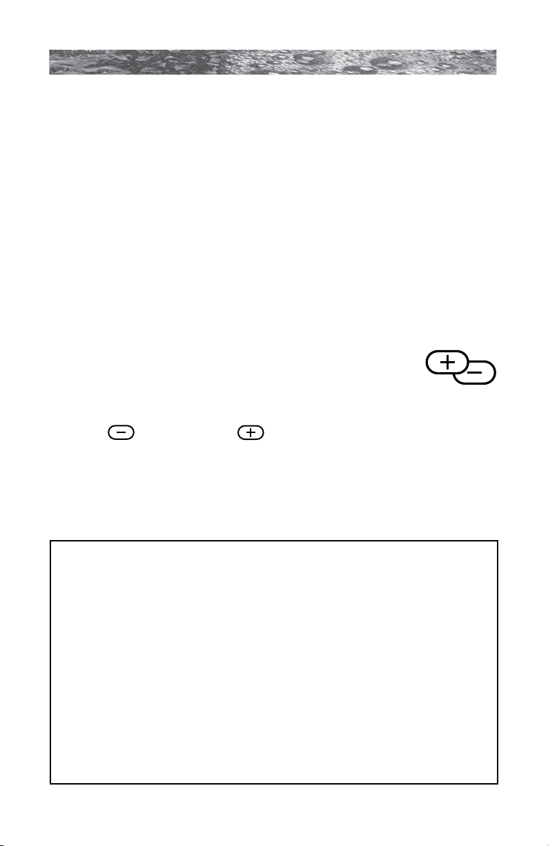
these steps:
• The LED display on the control panel displays the actual
temperature of the spa water. Press either the COOLER
( ) or WARMER ( ) button once to display the “set”
temperature for 5 seconds. If you want the water to heat to a
different temperature, simply press COOLER or WARMER within
5 seconds. The set temperature increases or decreases by one
degree each time one of these buttons is pressed.
• The heater will turn off when the temperature corresponding to
the thermostat setting is achieved.
Important Heater Details:
• The maximum temperature for which the spa can be set is 104°F
(40°C) and the minimum is 65°F (18°C).
• For North American (60 Hz) 2-pump spas powered by a 40 amp
service, jets pump #1 must be set to low speed and jets pump #2
must be turned off to operate the heater.
• For Export (50 Hz) 2-pump spas powered by a 20 amp service,
jet pump #1 must be set to low speed and jets pump #2 must be
turned off to operate the heater.
• Setting the thermostat at maximum will not accelerate the heating
process. This will only result in a higher ultimate temperature.
• The heater operates until the water reaches the programmed “set
temperature”, then turns off. The heater will reactivate after the
water cools to approximately 1.5° below the “set temperature.”
Page 17
Page 24
680 SERIES
8. Place Cover On Spa
• Keeping the insulating cover in place anytime the spa is not in
use will reduce the time required for heating, thereby minimizing
operating costs.
• The time required for initial heat-up will vary depending on the
starting water temperature.
DANGER: Risk of injury, always check water temperature
!
carefully before entering spa!
Decontamination Procedure (Steps 9-15)
Steps 9-15 below are only required when sanitizer levels are unstable
after performing steps 1-6 above. Disregard steps 9-15 below if sanitizer
levels remain stable at 3.0-4.0 ppm chlorine or 2.0-4.0 ppm bromine after
performing steps 1-6 above.
9. Add 2.5 ounces (71 g) of sodium dichlor for every 100 gallons (378
Liters) of water. Refer to the table below for approximate water ll
volume by model.
CAUTION: Never add chlorine tablets (trichlor) to your
spa for any reason! This chemical may damage components
!
within your spa and void the manufacturer warranty.
Water Fill Volume by Model
Spa Model Approximate Fill Volume Sodium dichlor
Denali .................298 US Gallons (1,128 Liters) ............... 7.5 oz.
Tacoma ............... 186 US Gallons ( 704 Liters) ............... 4.7 oz.
Burlington ...........435 US Gallons (1,647 Liters) ............. 11.0 oz.
Hartford ...............470 US Gallons (1,779 Liters) ............. 11.8 oz.
Hawthorne ..........400 US Gallons (1,514 Liters) ............. 10.0 oz.
Page 18
Page 25
680 SERIES
B
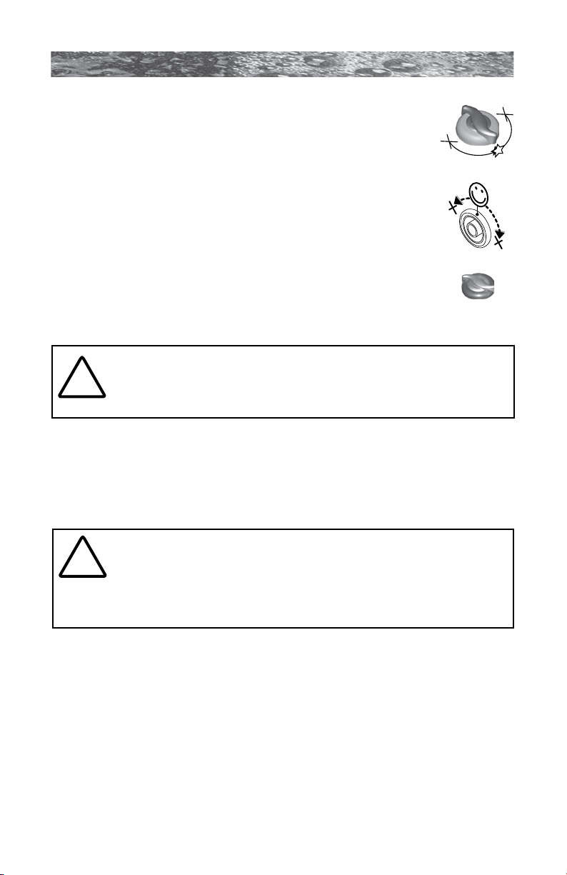
10. Leave spa cover open during this step to allow
Massage Selector
excessive chemical vapors to exit spa, protecting plastic
knobs and pillows on Burlington, Hartford, Hawthorne
and Tacoma models from chemical attack. If spa is
indoors, open doors and windows for proper ventilation.
Figure A
Turn on all spa jets pumps for one hour, open all air
controls. On Burlington, Hartford and Hawthorne (Figure
A) and Denali (Figure B) models, place the Massage
Selector or Diverter Jet in their center “combo” position
as shown (right).
Figure B
Note: You will need to press the jets pump button(s) every 20
minutes since these functions have an automatic 20 minute
time-out function that turns them off.
Set all air controls
to their full open
counterclockwise
position
CAUTION: Never leave your spa unattended for any reason
while the cover is open and accessible to small children and
!
animals!
11. Turn off power to the spa at the circuit breaker, then drain spa as
outlined in Section 11.2 (page 31).
12. Rell spa with clean tap water from garden hose until water covers
all jets (DO NOT OVERFILL!)
CAUTION: Never ll with water from a water softener. If your
water is extremely “hard”, it is preferable to ll half-way with
!
hard water and the rest of the way with softened water. Or,
you may ll entirely with hard water if you use a special water
additive available from your authorized Sundance dealer.
13. Consult your authorized Sundance dealer for chemical
recommendations, then add chemicals to spa water to achieve a
constant sanitizer reading within the levels recommended by the
Association of Pool And Spa Professionals/USA printed on the inside
cover of this manual.
14. Turn on all jet pumps when adding chemicals to ensure proper
mixing and leave your spa cover open until the sanitizer level falls
below 4.0 ppm to protect plastic knobs and pillows from chemical
attack.
Page 19
Page 26

680 SERIES
CAUTION: Never leave your spa unattended for any reason
while the cover is open and accessible to small children and
!
animals.
CAUTION: To prevent the unlikely possibility of contracting
a waterborne
!
6 parameters. If you or other bathers experience such a
condition, discontinue use and seek medical attention.
15. Establish a sanitizer reading between 3.0-4.0 ppm chlorine or
2.0- 4.0 ppm bromine, then allow the spa to set undisturbed for 8
hours. Retest water after 8 hours to determine if sanitizer levels
are stable. If sanitizer levels are stable, your spa is ready for use.
To ensure healthy water conditions, always maintain a constant
sanitizer reading within the levels recommended by the Association
of Pool And Spa Professionals/USA printed on the inside cover of
this manual. If sanitizer levels are not stable at this time, it will be
necessary to repeat this procedure in its entirety (steps 1-15) until
stable sanitizer readings are achieved.
16. After adequate sanitizer levels are achieved, close all spa air controls
by rotating them clockwise to maximize heat retention when spa is
not in use.
illness, maintain water chemistry within step
Page 20
Page 27
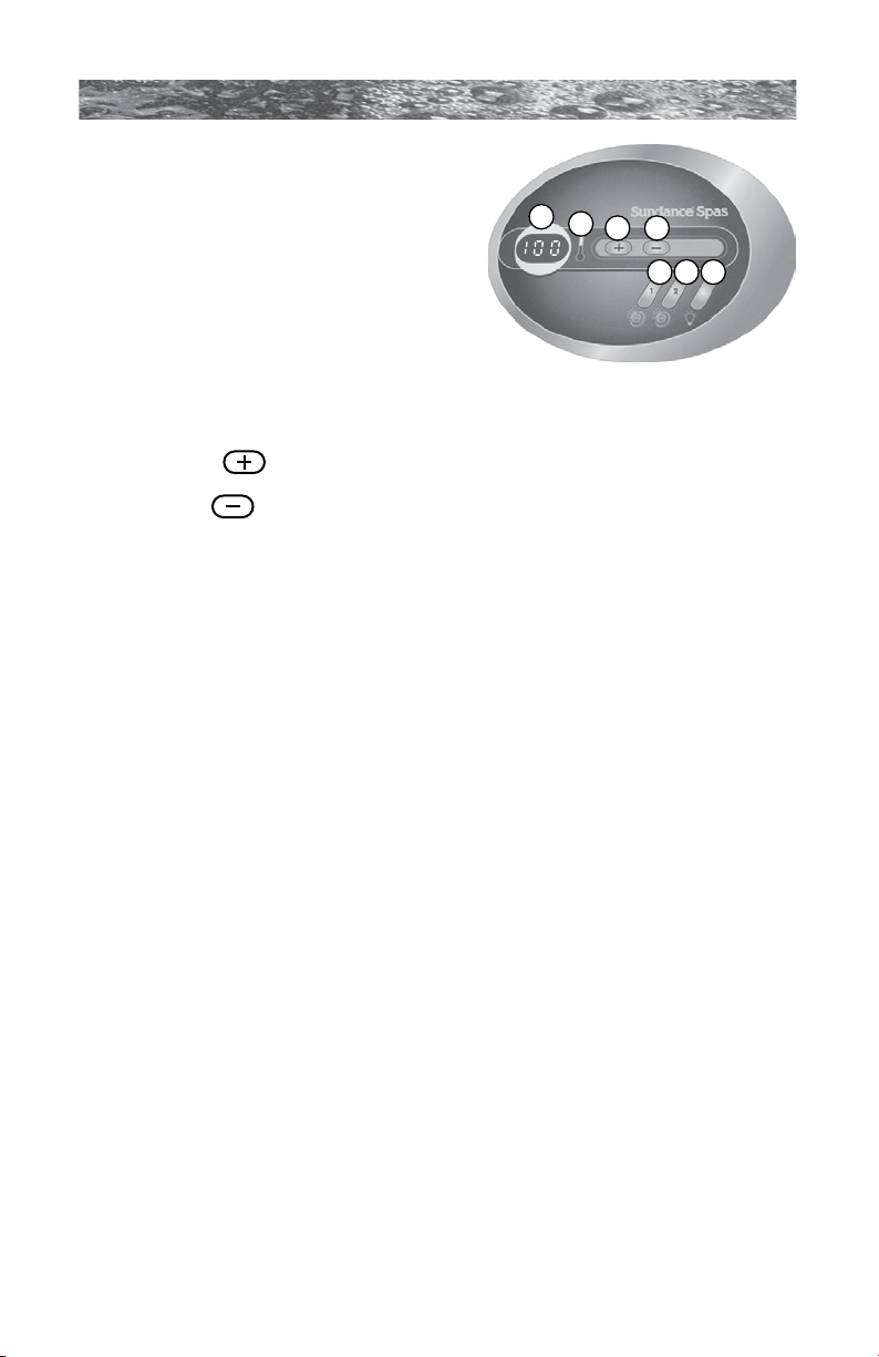
8.0 Control Functions
A
B
C D
E F G
8.1 Control Panel A. LED Display: Can display current
water temperature (default display),
water temperature set point, selected
ltration/heating mode, and error
messages.
680 SERIES
B. Heat Indicator: Lit when heater is
2 Pump Panel Shown
on.
C. Warmer ( ) Button: Increases water temperature set point.
D. Cooler ( ) Button: Decreases water temperature set point.
E. Jets 1 Button: Turns jets pump #1 on and off. Press once for low
speed; press a second time for high speed; press a third time to turn
pump off.
F. Jets 2 Button (Hartford and Hawthorne Models): Turns jets pump
#2 on and off. Press once for high speed; press a second time to turn
pump off.
G. Light Button:
• Denali and Tacoma Models: Turns underwater light on in random
mode or in one of six solid colors. Refer to Section 9.3 (page 24)
for details.
• Burlington, Hartford and Hawthorne Models with standard
Incandescent light system: Turns underwater light on and off.
Refer to Section 9.4 (page 24) for details.
• Burlington, Hartford and Hawthorne Models with optional LED
lighting system: Turns underwater light and top rim accent lights
on in one of three random modes or one of seven solid colors.
Refer to Section 9.5 (page 24) for details.
Operation Details
• Temperature Adjustment: 65 to 104°F (18 to 40°C). Factory
default setting is 100°F (38°C).
• All lighting systems run for 1 hour then shut off.
• Jets 1/Jets 2 Button Operation: Jets run for 20 minutes after
activated, then turn off automatically to conserve energy. Simply
press either jets button to continue operation for an additional 20
minutes.
Page 21
Page 28
680 SERIES
1
9a
10
11
12
2
3
4
4
5
4
2
2
2
12 3 36
7
3
12
12
9b
12
8
8
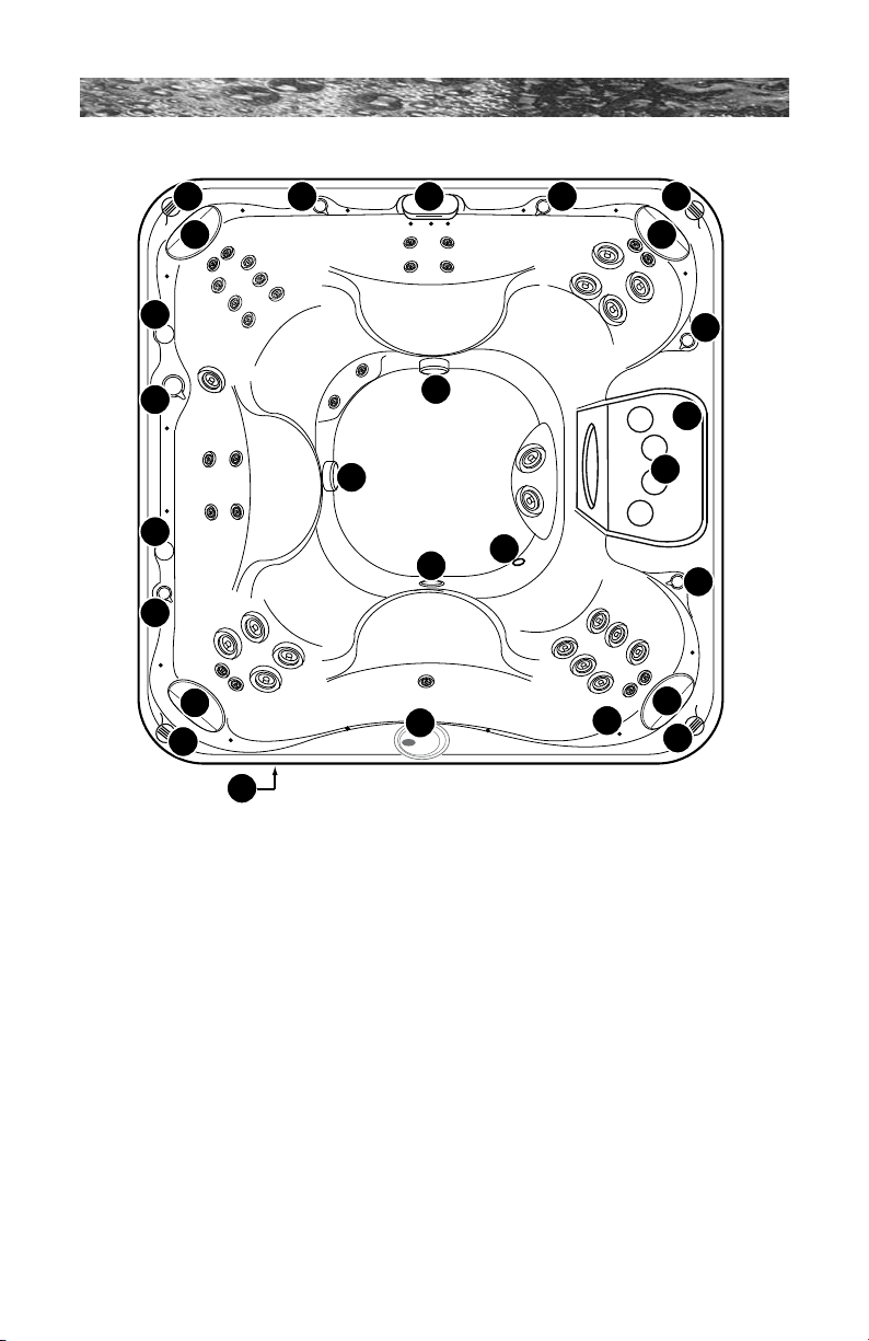
8.2 General Spa Features And Controls
1. Control Panel
2. Headrest Pillows (4 ea.)
3. Air Controls (4 ea.)
4. Cup Holders (6 ea.)
5. Massage Selector (1 ea.)
6. Waterfall
7. Waterfall control valve (1 ea.)
8. Suction Fittings & Fitlers (Filters
protect massage selector from debris
entrapment/damage. Filters require
periodic cleaning. (2 ea.)
9. Lighting System Options:
• Standard Underwater light system
includes incandescent light (9a).
• Optional LED lighting system includes
LED footwell light (9a) and multiple led
accents lights (9b).
Page 22
Hartford model illustrated - Jet locations and features will vary
by model. Specifications subject to change without notice.
10. Gravity Drain: Fitting functions as floor
11. Filter lid with four cup holders and two
• Spas without the circulation pump
• Spas with the circulation pump option
12. Optional audio system speakers (4 ea.)
gravity drain, heater return and optional
CD ozone return.
underlying lter cartridges.
option utilize both lter cartridges for
jets pump 1.
utilize one lter cartridge closest to
waterfall valve (7) for jets pump 1 and
the second cartridge for the 24 hour
circulation pump.
and AM/FM/CD stereo deck (1 ea.)
located on front spa skirt.
Page 29
680 SERIES
1.
2.
3.
1
2
9.0 Operating Instructions
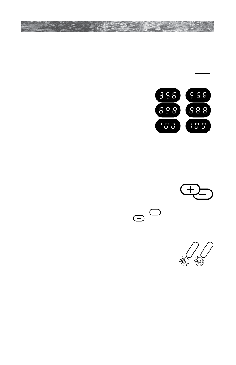
The spa control system has automatic functions that operate upon
start-up and normal operation to protect the system. Upon power up, the
readout displays the following information:
1. Control panel displays current software
release (e.g. 3.56 or 5.56 depending on spa
Spa with
Circulation
Pump Option
Spa without
Circulation
Pump Option
model), then;
2. Control panel displays “888” and all
indicator LEDs are lit, permitting visual
inspection of all display segments and
indicator lights for proper operation.
3. After the initial start-up sequence ends, the
actual water temperature is displayed. If
water temperature at this time is less then
the factory default temperature setting of
100°F (38°C) and the spa is set to either of the standard ltration/
heating modes (pages 28-29), the heater will turn on and run until the
water temperature rises to the factory setting, then turn off.
Note: It is common for the heater to turn on after the spa is rst lled
because tap water is often very cold.
9.1 Setting Water Temperature
The spa’s thermostat provides optimum control of water
temperature. The temperature setpoint (set temperature)
can be adjusted from 65°F to 104°F (18°C to 40°C). To
raise the set temperature, press the WARMER ( ) button. To lower
the set temperature, press the COOLER ( ) button.
Note: The rst press of either button displays the set temperature.
9.2 Activate Pumps
The JETS 1 button activates the jets pump 1. The rst
press activates in low speed, the second press activates
high speed, and the third press shuts the pump off. The
JETS 2 button (Hartford and Hawthorne models only)
activates jets pump 2 which only operates in high speed.
When manually activated, both pumps automatically turn
off in 20 minutes.
Page 23
Page 30

680 SERIES
Random
Off
Blue
OFF
OFF
OFF
OFF
Green
Orange
OFF
OFF
Red
Violet
Teal
9.3 SunGlow™ Light Operation (Denali and Tacoma Models)
The spa light offers 6 constant color variations and a unique random
mode for enhanced spa enjoyment. Press the Light button once to turn
the spa light on in Random mode, then repeatedly press the button to
turn the light off or to select one of 6 constant colors as illustrated below.
You must press the LIGHT button within 5 seconds between each “off”
or “color” selection to prevent it from resetting. Pressing the button
after 5 seconds restarts the sequence in Random mode. This mode
automatically changes the light color every 8 to 20 seconds.
Note: Any time the spa light is manually turned on, it will automatically
turn off after approximately 1 hour. If you desire more light at this time,
simply turn the light back on.
9.4 Standard Light Operation (Burlington, Hartford and
Hawthorne Models)
The light button activates the footwell light in the spa when
pressed. Pressing the button turns the footwell light off. When
manually activated, the footwell light will automatically turn off
after one hour.
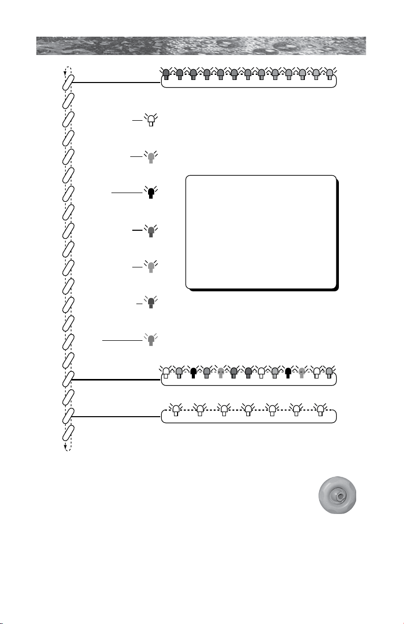
9.5 Optional Multi-Colored LED Light System Operation
(Burlington, Hartford and Hawthorne Models)
The multi-colored LED spa light offers seven constant color variations
and three unique random modes for enhanced spa enjoyment. Press
the light button once to activate the rst light mode Random Fade, then
continue pressing the button to either turn the light off or to select one
of seven constant colors, random solid color mode or strobe mode as
illustrated below.
Page 24
Page 31
680 SERIES
Press
Once
Lights display hunderds of colors in 5-6 second intervals.
Lights display different solid color every 5-6 seconds
= off
= NEAR WHITE
= off
= LIGHT BLUE
= off
= VIOLET
= off
= DARK BLUE
= off
= LIME GREEN
= off
= DARK GREEN
= off
= RED
= off
= off
= off
Lights flash “strobe” in white color
Light Operation Tips:
You must press the light button within 3
seconds of any “off” condition or the light
sequence will revert back to “Random
Fade” mode, when reactivated.
Any time the spa light is manually
activated, it will remain on for 1 hour then
automatically shut off.
= RANDOM FADE
= RANDOM SOLID
= STROBE
9.6 Adjusting Individual Jet Flow
The water ow through individual jets in your spa can be
adjusted or turned off by rotating the outside jet ring. Many
jets also offer an adjustable center nozzle that allows you to
change the water discharge angle. Simply tilt the center
nozzle in these jets to the desired angle to customize your
personal massage.
Note: Always keep at least 6 adjustable jets open at all
times to ensure proper ltration characteristics within spa.
Page 25
Page 32
680 SERIES
B
A
C
A
B
C
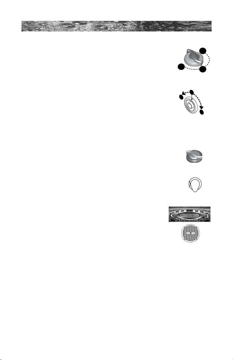
9.7 Selecting Desired Massage Action
All models (except Tacoma) incorporate a massage selector
valve or Diverter Jet that allows you to customize the
massage and performance by diverting water between
various jet systems within the spa. Simply turn valve to
positions A, B or C to divert water pressure to various jet
groups.
Burlington, Hartford
and Hawthorne
models
Note: The valve is intended to operate in positions
A (Combo), B, or C for optimum performance. It is
considered normal for sound levels within the valve
to increase between these positions due to the large
amounts of water owing through it. For optimum ltration
Denali model
benets, always leave this valve in position A when the
spa is covered and select positions B or C for maximum jet performance
during spa use.
9.8 Air Controls
Certain jet systems have their own air control. Each
control introduces air into the water lines that supply that
specic jet group. Simply turn the air control selection
Burlington, Hartford
and Hawthorne
models
to open or close. To minimize heat loss, all air controls
should be closed when the spa is not in use.
Denali model
9.9 Optional Audio System
Burlington, Hartford and Hawthorne models equipped
with the optional audio system offer enhanced spa
enjoyment. These models include a high-quality AM/FM/CD
stereo receiver with four high-quality marine speakers for
unsurpassed sound quality and long-life. Refer to Section
21.0 (page 46) for complete stereo operation details.
Page 26
Page 33

680 SERIES
10.0 Automatic Filtration Cycles
The control system activates a programmable “standard” or “economy”
filtration cycle to remove debris from your spa. These cycles use the low
speed pump, skimmer basket, and filter cartridge quickly clear “skim” the
water of debris and minimize their “bathtub ring” affect. Apart from their
filtration benefit, each mode also effects the operation of your spa’s heater.
Refer to Sections 10.1-10.3 below for additional information.
10.1 Standard Filtration/Heating Modes For Models Without Circulation Pump Option
Standard filtration/heating modes (F1-F3) are typically selected by
customers in cold climates where heat up times are extended due
to lower ambient temperatures. In either of these modes, the water
temperature is regulated by the set temperature, low-speed jets pump
1 and heater which turns on as needed. After the programmed set
temperature is reached, the heater and low speed pump turn off, only to
turn back on during a heat call or during the next programmed filtration/
heating cycle.
10.2 Standard Filtration/Heating Modes For Models With Circulation Pump Option
Standard filtration/heating modes (F0-F3) are typically selected by
customers in cold climates where heat up times are extended due
to lower ambient temperatures. In either of these modes, the water
temperature is regulated by the set temperature, 24 hour circulation
pump and heater which turns on as needed. After the programmed set
temperature is reached, the heater turns off and the circulation pump
continues to operate 24 hours to filter and clean your spa.
10.3 Economy Filtration/Heating Modes (F4-F6)
Economy ltration/heating modes are typically selected by customers in
warm climates where heat up times are minimized due to higher ambient
temperatures. In these modes, the water temperature is regulated by the
set temperature, low-speed pump, optional circulating pump and heater
only while a programmed filtration/heating cycle is running.
Note: These modes consume less energy than standard modes F1-F3
outlined above.
10.4 Lock Modes (L1-L2)
These modes are designed for use during spa service or to prevent
unauthorized use.
Page 27
Page 34
680 SERIES
10.5 Selecting The Filtration/Heating Mode
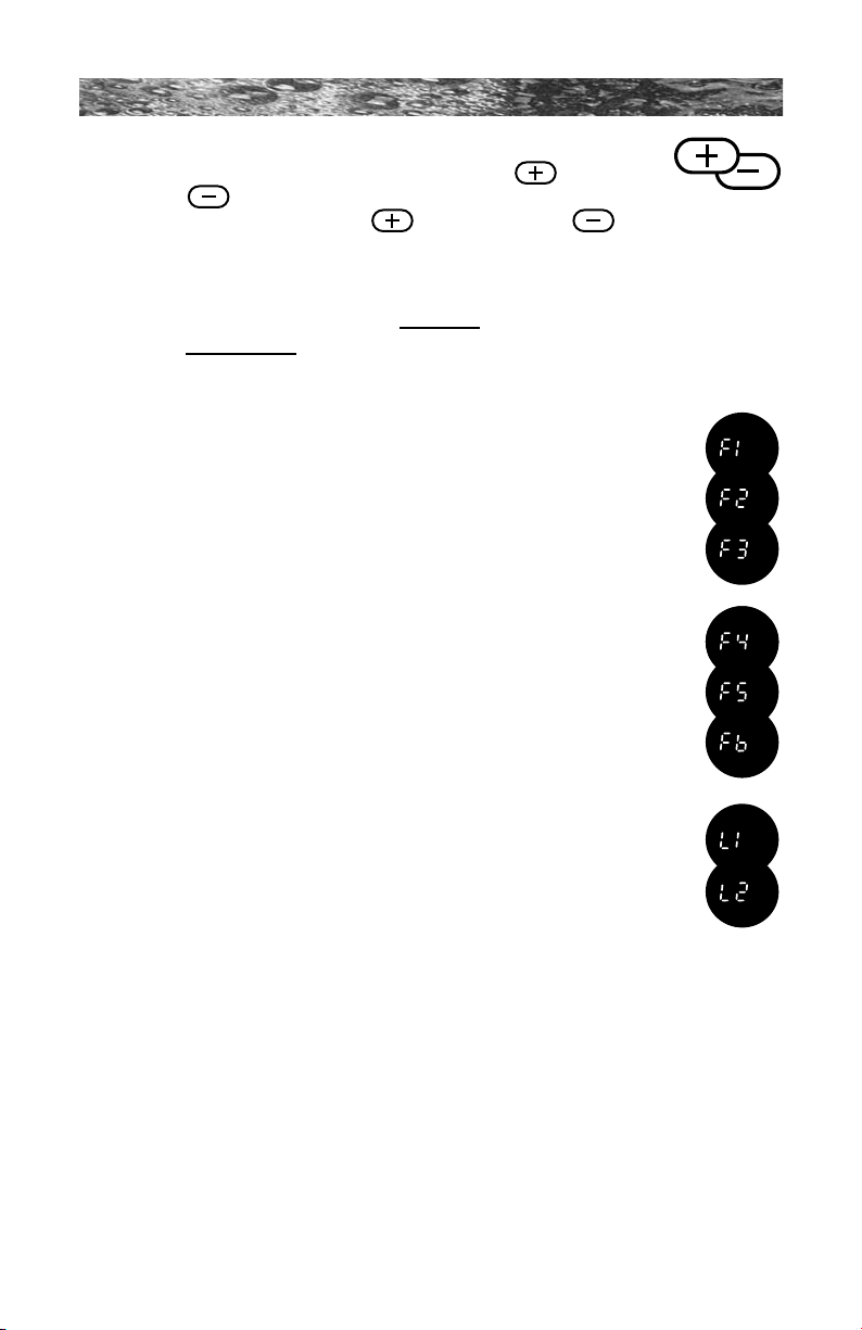
Press and hold both control panel WARMER ( ) and
COOLER (
) buttons at the same time, then release.
Then press either WARMER ( ) or COOLER ( ) button to select
ltration/heating mode F1-F6 or lock modes L1-L2 on the following
pages.
10.6 Filtration Modes for Spas Without Circulation Pump Option
If your spa is equipped with the circulation pump option, disregard this
section and refer to page 29 for lter cycle programming details.
Standard Filtration/Heating Modes (F1-F3)
F1 4 hours of ltration/heating per day (one 2-hour cycle every
12 hours).
F2 6 hours of ltration/heating per day (one 2-hour cycle every
8 hours).
F3 8 hours of ltration/heating per day (one 2-hour cycle every
6 hours).
Economy Filtration/Heating Modes (F4-F6)
F4 4 hours of ltration/heating per day (one 2-hour cycle every
12 hours).
F5 6 hours of ltration/heating per day (one 2-hour cycle every
8 hours).
F6 8 hours of ltration/heating per day (one 2-hour cycle every
6 hours).
Lock Modes (L1-L2)
L1 Lock Out (disables all spa functions to permit lter
cleaning).
L2 Lock Mode (disables the jets and light buttons to prevent
unauthorized use of spa). Filtration/heating cycle will
continue to operate as programmed in this mode. The
temperature display ashes when this function is enable.
Example: the “F3” ltration/heating cycle was enabled prior to
choosing lock mode. The spa continues to perform the “F3” cycle
until lock mode is canceled, allowing another cycle to be selected.
Filter Cycle Setup Example
To set a time for the rst ltration/heating cycle, simply turn power on to
the spa two minutes prior to the desired time. Example: If you desire your
rst ltration/heating cycle to begin at 10:00 AM turn off power to the spa
and turn it back on again at 9:58 AM.
Note: Start time is approximate and may vary slightly from day to day.
Page 28
Page 35

680 SERIES
10.7 Filtration Modes for Spas With Circulation Pump Option
If your spa is not equipped with the circulation pump option, disregard
this section and refer to page 28 for lter cycle programming details.
Standard Filtration/Heating Modes (F0-F3)
(Heater automatically turns on during any heat call while in
any Standard mode).
F0 5 minutes of ltration per day (one 5 minute “Blow-Out”
cycle every 24 hours to purge all plumbing lines)
F1 1 hour of ltration per day (one 30-minute cycle every
twelve hours); this is the factory default setting.
F2 1.5 hours of ltration per day (one 30-minute cycle every
eight hours).
F3 2 hours of ltration per day (one 30-minute cycle every six
hours).
Economy Filtration/Heating Modes (F4-F6)
(Heater can only turn on during an active lter cycle while in
any economy mode).
F4 1 hour of ltration/heating per day (one 30-minute cycle
every twelve hours).
F5 1.5 hours of ltration/heating per day (one 30-minute
cycle every eight hours).
F6 2 hours of ltration/heating per day (one 30-minute cycle
every six hours).
Lock Modes (L1-L2)
L1 Lock Out (disables all spa functions to permit lter
cleaning).
L2 Lock Mode (disables the jets and light buttons to prevent
unauthorized use of spa). Filtration/heating cycle will
continue to operate as programmed in this mode. The
temperature display ashes when this function is enable.
Example: the “F3” ltration/heating cycle was enabled prior to
choosing lock mode. The spa continues to perform the “F3” cycle
until lock mode is canceled, allowing another cycle to be selected.
Filter Cycle Setup Example
To set a time for the rst ltration/heating cycle, simply turn power on to
the spa two minutes prior to the desired time. Example: If you desire your
rst ltration/heating cycle to begin at 10:00 AM turn off power to the spa
and turn it back on again at 9:58 AM.
Note: Start time is approximate and may vary slightly from day to day.
Page 29
Page 36
680 SERIES
11.0 Spa Maintenance
Proper and regular maintenance of your spa will help it retain its beauty
and performance. Your authorized Sundance dealer can supply you with
all the information, supplies, and accessory products you will need to
accomplish this.
DANGER: Risk of Severe Injury or Drowning!
The suction ttings in this spa are sized to match the specic
!
water ow created by the pump. If it is necessary to replace
the suction ttings or the pump, be sure that the ow rates
are compatible.
Never operate or use the spa if the lter, lter lid, or •
skimmer assembly are broken or any part of the skimmer
assembly is missing. Please contact your dealer or nearest
service center for service.
Never replace a suction tting with one rated less than •
the ow rate marked on the original suction tting. Using
improper suction ttings can create a body or hair suction
entrapment hazard that may lead to drowning or near
drowning.
Never use the spa unless all suction guards, lter, lter lid, •
or skimmer assembly are installed to prevent body and/or
hair entrapment.
Keep hair, loose articles of clothing or hanging jewelry •
away from suction ttings, rotating jets or other moving
components to avoid entrapment that could lead to
drowning or near drowning.
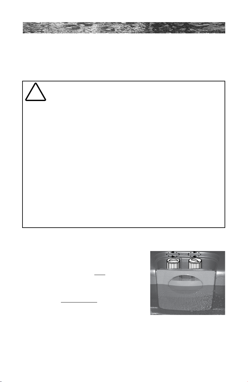
11.1 Cleaning The Filter A. Burlington, Hartford and Hawthorne
To Remove: Turn
Counterclockwise
To Install: Turn
Clockwise
Models:
Your spa is equipped with two filter cartridges
which are utilized as follows:
• Models equipped with the optional 24
hour circulation pump use cartridge 1
Cartridge 2
Cartridge 1
for the circulation pump and cartridge
2 for jets pump 1.
• Spas not equipped with the optional
Spa Filter Bay
24 hour circulation pump use both
lter cartridges for jets pump 1.
During spa use or an automatic filter cycle, water flows through the
spa skimmer and into both polyester mesh filter cartridges to trap
suspended particles and oils on their surface pleats. To ensure optimum
performance, it is necessary to remove and clean both filter cartridges
once a month or sooner depending on spa use and water quality.
Page 30
Page 37

680 SERIES
B. Denali and Tacoma Models:
Your Sundance spa is equipped with a skimmer basket and lter
cartridge located in the skimmer/lter well. Filtering is accomplished
when the pump turns on in low speed to initiate water ow through the
skimmer basket and polyester mesh lter cartridge. As this happens,
suspended particles become trapped on the lter’s surface. To ensure
optimum performance, it is necessary to remove and clean the skimmer
basket once a week and lter cartridge once a month or sooner,
depending on usage and water quality.
C. Cleaning Procedure (for All Models):
1. Turn off power to the spa at the home’s breaker panel or select
the L1 “Lock” mode (page 27) to disable all spa functions.
2. Remove the lter strainer lid assembly.
3. Remove the lter cartridge by rotating it counterclockwise to
unthread it from the lter wall tting, then lift it straight up to remove
from lter well.
4. Using a garden hose with a high-pressure nozzle to rinse debris from
the lter pleats beginning at the top and working your way downward.
Continue, one section at a time, until you have rinsed all of the lter’s
pleats.
Periodically, the filter cartridge will need a more thorough cleaning to
remove imbedded oils and minerals. For this, we suggest cleaning as
above and then soaking the cartridge overnight in a plastic container
filled with a solution of water and a specially formulated filter cleanser
available from your authorized Sundance dealer. The average life
expectancy of a Sundance filter cartridge is approximately two years
with proper care and water quality maintenance. A replacement cartridge
may be purchased from your dealer.
11.2 Draining and Refilling
About every 3 months, you will want to replace the spa’s water. The
frequency depends on a number of variables including the amount of
use, attention paid to water quality maintenance, etc. You will know it is
time for a change when you cannot control sudsing and/or you can no
longer get the normal feel or sparkle to the water even though the key
water balance measurements are all within the proper parameters.
Page 31
Page 38
680 SERIES
WARNING! READ THIS BEFORE DRAINING: To prevent
damage to the spa’s components, turn off power to the spa
!
at the circuit breaker before draining it. Do not turn the
power back on until your spa has been relled.
CAUTION: There are certain precautions to keep in mind
when draining your spa. If it is extremely cold, and the spa is
!
outdoors, freezing could occur in the lines or the equipment
(see “WINTERIZING”, page 33). On the other hand, if it is hot
outdoors, do not leave the spa’s surface exposed to direct
sunlight.
To drain your spa, perform the following steps:
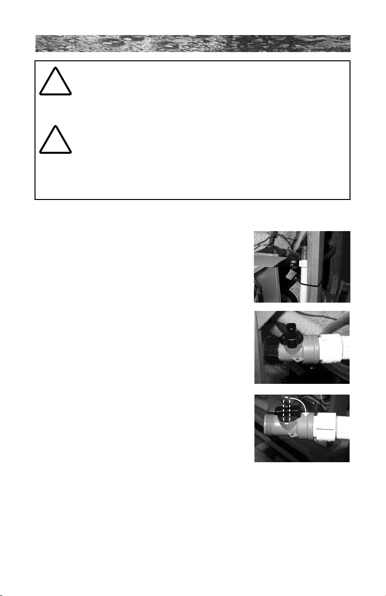
1. Turn off power to spa at breaker.
2. Locate and remove the synthetic cabinet door
screws and door. The door is located directly
below the control panel and is easily identied
by it’s vertical cooling slots.
3. Locate drain hose line attached to 2 x 4 wood
slat (Figure A) with tie wraps.
4. Cut tie wraps and pull drain hose from
equipment area (Figure B).
5. Hold drain hose above water line (Figure B),
then unthread drain cap (1) from hose using
a counterclockwise rotation. Place hose on
ground making sure to direct water away from
spa.
6. Turn valve (2) clockwise to open drain (Figure
C).
7. After spa has completely drained, reinstall
drain cap on drain valve nger tight! DO
NOT OVERTIGHTEN! Close valve by turning
clockwise to off position.
8. Place drain hose back inside the spa
equipment bay.
9. Reinstall synthetic cabinet door and screws.
10. After relling spa, turn on power and follow the “Spa Fill Up
Procedure” (page 16).
Figure A
2
1
Figure B
Figure C
11.3 Pillow Care (All Models Except Denali)
Remove and clean the headrest pillows as needed with soapy water
using a cloth or soft-bristle brush. To maintain water resistance and
Page 32
Page 39

680 SERIES
luster, apply a quality vinyl conditioner once a month. Always remove
the pillows when adding chemical shock treatment to the spa water.
The pillows can be returned to the spa when the sanitizer reading drops
below 4 ppm.
11.4 Cleaning The Spa Interior
To preserve the sheen of your spa’s surface, it is crucial that you avoid
using abrasive cleaners or cleaners which have adverse chemical effect
on the surface. If you are not certain as to the suitability of a particular
cleanser, consult your authorized Sundance dealer. Regardless of the
cleanser used, use extreme care to assure that no soap residue is left on
the surface. This could cause severe sudsing when the spa is relled.
11.5 Maintaining The Cover
Using the Sundance insulating spa cover anytime the spa is not in
use will signicantly reduce your operating costs, heat-up time and
maintenance requirements. To prolong the life of the cover, handle it with
care and clean it regularly using mild soap and water. Periodic treatments
with a special conditioner developed for Sundance spa covers will help
protect against deterioration caused by UV rays from the sun.
Note: Never allow anyone to stand or sit on the cover, and avoid
dragging it across rough surfaces.
11.6 Maintaining The Synthetic Cabinet
Your new spa’s synthetic cabinet requires little or no maintenance of
any kind. To clean, simply wipe cabinet with a clean towel and mild soap
solution.
CAUTION: Never spray cabinet with a garden hose for any
reason since this action may induce an electrical short in the
!
spa’s electrical equipment.
11.7 Winterizing
Your Sundance® spa is designed to automatically protect itself against
freezing when operating properly. During periods of severe freezing
temperatures, you should check periodically to be certain that the
electrical supply to the spa has not been interrupted. In extreme, bitter
cold weather less than -20°F (-29°C), choose the F3 “Standard” ltration/
heating mode to prevent freezing (pages 28-29).
If you do not intend to use your spa, or if there is a prolonged power
Page 33
Page 40

680 SERIES
outage during periods of severe freezing temperatures, it is important
that all water be removed from the spa and equipment to protect against
damage from freezing. For expert winterization of your spa, contact
your authorized Sundance dealer. In emergency situations, damage
can be minimized by taking the following steps:
1. Follow the directions on pages 31-32 for draining the spa.
2. As the water level drops below the seats, use whatever means
necessary to get the water out of the recessed seating areas and into
the footwell.
3. When the water level ceases to drop, use whatever means available
to remove any remaining water from the footwell.
4. Turn off power to the spa.
5. Remove the equipment-side cabinet panel and locate the drain plugs
in the front of the pump(s) (Figure A, page 14). Remove these plugs
to allow the water to drain out of the pumps and heater.
Note: Approximately one to two gallons will be released during this
procedure. Use a wet/dry vacuum or other means to keep this from
ooding the equipment compartment. Replace the pump drain plugs.
6. Re-install cabinet side panels and cover spa so that no casual
moisture can enter into it.
Consult your authorized Sundance dealer if you have any questions
regarding winter use or winterizing.
11.8 Restarting Your Spa in Cold Weather
If you want to start up your spa after it has sat empty for a time in
freezing temperatures, be aware that the water remaining in certain
sections of the piping may still be frozen. This situation will block water
ow preventing the spa from operating properly and possibly damaging
the equipment. We recommend you consult your authorized Sundance
dealer for guidance before attempting to re-start your spa under these
conditions.
12.0 Water Quality Maintenance
Maintaining the quality of the water within specied limits will serve to
enhance your enjoyment and prolong the life of the spa’s equipment. It
is a fairly simple task, but it requires regular attention because the water
chemistry involved is a balance of several factors. There is no simple
formula, and there is no avoiding it. A careless attitude in regard to water
maintenance will result in poor and potentially unhealthful conditions
Page 34
Page 41
680 SERIES
for soaking and even damage to your spa. For specic guidance on
maintaining water quality, consult your authorized Sundance dealer
who can recommend appropriate chemical products for sanitizing and
maintaining your spa.
CAUTION: Never store spa chemicals inside the spa’s
equipment bay.
!
12.1 pH Control
pH is a measure of relative acidity or alkalinity of water and is measured
on a scale of 0 to 14. The midpoint of 7 is said to be neutral, above which
is alkaline and below which is acidic. In spa water, it is very important to
maintain a slightly alkaline condition of 7.4 to 7.6 pH. Problems become
proportionately severe the further outside of this range the water gets.
A low pH will be corrosive to metals in the spa equipment. A high pH will
cause minerals to deposit on the interior surface (scaling). In addition,
the ability of the sanitation agents to keep the spa clean is severely
affected as the pH moves beyond the ideal range. That is why almost all
spa water test kits contain a measure for pH as well as sanitizer.
12.2 Sanitizing
To destroy bacteria and organic compounds in the spa water, a sanitizer
must be used regularly. Chlorine and bromine are the two most popular
sanitizers used to date. Many other additives are available for your spa.
Some are necessary to compensate for out-of-balance water, some aid
in cosmetic water treatment and others simply alter the feel or smell of
the water. Your authorized Sundance dealer can advise you on the use of
these additives.
CAUTION: Do not use chlorine tablets (trichlor) in your spa.
This chemical can have an extremely corrosive effect on
!
certain materials in the spa. Damage caused by use of this
chemical, or improper use of any chemicals, is not covered
under the spa’s warranty.
12.3 CD Ozone Water Maintenance System
This system is optional on North American models and standard
equipment on export 50 Hz spa models. If your spa is equipped with the
optional Sundance CD Ozone water purication system you will nd that
your water stays fresh and clear with signicantly less chemical sanitizer
usage. You will also probably be able to go longer between complete spa
drainings.
Page 35
Page 42
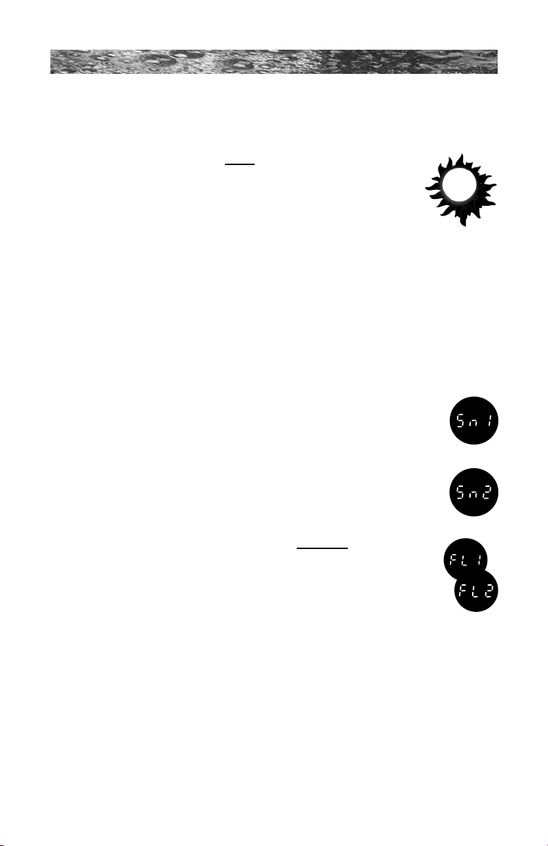
680 SERIES
13.0 Error Conditions/Error Messages
Your spa has a self-diagnostic control system. The system will
automatically display the following if a problem is detected.
13.1 Summer Logic (Spas With Circulation Pump
Option)
When the actual spa water temperature reaches up to 2
°F (1 °C) above the set temperature, the spa goes into
“summer logic.” The 24 hour circulation pump will turn off
automatically to avoid adding additional heat to the water,
eventually creating an overheat condition. This setting is not user-
programmable.
Note: The summer logic does not take effect until the spa water
temperature reaches 95°F (35°C). This condition is more likely in
excessively hot weather. Remember, the spa’s ability to cool is directly
affected by the ambient temperature. An excessively hot ambient
temperature may prevent the spa from cooling down because it’s
fully insulated construction is designed to retain heat and to minimize
operating costs.
13.2 Panel displays SN1
Open sensor (heater is disabled) or shorted sensor (spa
is deactivated). The high-limit temperature sensor is not
functioning. Your authorized Sundance dealer must repair this.
13.3 Panel displays SN2
Open or shorted sensor (heater disabled). The temperature
sensor is not functioning. Your authorized Sundance dealer
must repair this.
13.4 Panel Flashes FL1 or FL2 (Spas Without Circulation
Pump Option)
A flashing “FL1” display means the pressure switch is not
closed when the jets pump 1 is activated. Proper waterflow is
inhibited or the pressure switch has malfunctioned. A flashing
“FL2” display means the pressure switch is manfunctioning
closed. In either case, the heater is deactivated. To correct condition,
perform to the following:
1. Verify water level is one inch below lowest pillow. Add water if
necessary.
2. Check for clogged or excessively dirty filter cartridges (Section 11.1,
page 30).
3. Purge “air lock” from jets pump 1 by loosening the upper pump head
drain screw (Figure A, page 14) for a few seconds to release trapped
air, then retighten drain screw. FINGER TIGHT ONLY!
4. If problem persists, contact your authorized Sundance dealer.
Page 36
Page 43

680 SERIES
13.5 Panel Flashes FL1 or FL2 (Spas With Circulation
Pump Option)
A ashing “FL1” display means the ow switch is malfunctioning
open, the circulation pump lter cartridge 1 is excessively dirty
or an “air lock” condition has occurred at the circulation pump
intake. A ashing “FL2” display means the ow switch is
malfunctioning closed. In either case, the spa heater will
deactivate and jets pump #1 may also deactivate. To correct
condition perform the following:
1. Verify water level is 1" below lowest pillow. Add water if necessary.
2. Check for clogged or excessively dirty lter cartridges (Section 11.1,
page 30)
3. Purge “air lock” from circulation pump intake by removing lter
cartridge 1 (page 30). Hold your garden hose over the lter cartridge
1 wall tting (with grate) while using a rag as a seal around hose end.
Ask a helper to turn on water for 30 seconds, then turn off. Reinstall
lter cartridge 1 and check spa (Section 11.1, page 30).
4. If the circulation pump is not running, turn power off at the main
breaker, then turn power back on. This will reset the circulation pump
priming cycle. Once the pump is primed, the error should clear.
5. If problem persists, contact your authorized Sundance dealer.
13.6 Panel displays COL
Cool Condition - Temperature has dropped 20°F (11°C) below
the current set temperature. The pump and heater have been
activated to bring the temperature to within 15°F (8°C) of the set
temperature. No corrective action is required.
Note: During cold periods, you may consider increasing the number of
ltration cycles (pages 28-29).
13.7 Panel Displays ICE
Freeze Protection - A potential freeze condition has been
detected. No action is required. The pump and heater will operate
to circulate and warm water through the plumbing spa is out of
danger. See “Winterizing” Section 11.7 for details (page 33).
13.8 Panel Displays OH
Water temperature is above acceptable limits. Do not enter spa!
Water temperature has reached 112°F (44°C) and the low speed
pump has activated to circulate water through heater.
Page 37
Page 44

680 SERIES
13.9 Panel displays - - -
The safety “Watchdog” software has been triggered and the
spa is deactivated. A problem has been detected which could
cause damage to the spa or its components. Contact your
authorized Sundace dealer.
14.0 Troubleshooting Procedures
In the event your spa is not working the way it should, please rst review
all the installation and operating instructions in this manual and check the
message on the panel display. If you are still not satised it is working
properly, please follow the appropriate troubleshooting instructions below.
Note: If any of the supply cords to the accessories are damaged, they
must be replaced by authorized service personnel.
14.1 None of the Components Operate (e.g. Pump, Light)
Check the following when none of the spa components operate
(e.g. jets pumps or light):
1. Is there power to the spa?
2. Is the household circuit breaker tripped?
3. Call your authorized dealer.
14.2 Pump Does Not Operate but Light Does
Press the JETS 1 Button:
1. If no water movement is detected, make sure power is going to
the spa and check the water level. If it does not solve the problem,
contact your authorized Sundance dealer.
2. The main pump operates but no water ows to jets. Pump may not
be properly primed. This can happen after the spa is drained and
relled. Press the JETS 1 button several times, never leaving the
motor on for more than 5 to 10 seconds at a time. Turn power off
and let the air out removing the lter cartridge. Refer to Section 11.1
(page 30). Make certain you reinstall the lter cartridge before turning
on spa power and restarting the jets pump.
Page 38
Page 45

680 SERIES
14.3 Poor Jet Action
1. Press the JETS 1 button to make certain the pump #1 is on.
2. Open all air control to the “on” position.
3. Check for dirty lter. Clean, if necessary.
4. Make sure jets are all the way open.
14.4 Water is Too Hot
Reduce thermostat setting.
14.5 No Heat
1. Check thermostat setting.
2. Keep the spa cover in place while heating.
3. Check the settings to see if your spa is in economy ltration/heating
mode (pages 28-29).
Should checking the above steps fail to correct the problem, please call
your dealer so that they may arrange service.
We build the best spas in the industry. Nonetheless, we are always
striving to improve the quality and features of our products. Your input as
a Sundance spa owner is a cherished part of this process. If you have
any comments or suggestions, or if you wish to be informed on any new
products for your spa, please write to us.
CONGRATULATIONS on your good taste and welcome to the happiest
and most relaxed family in the world!
Page 39
Page 46
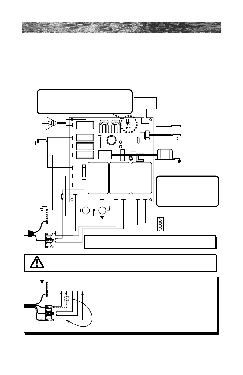
680 SERIES
Optional
Ozonator
O
3
Standard 3-Wire 120 VAC Connection (60 Hz, 1 Phase, 15A Service)
Use copper conductors ONLY. Wire size must be appropriate per NEC and/or local codes.
WHT
WHT
WHT
WHT
WHT
WHT
BLK
BLK
BLK
BLK
BLK
BLK
BLK
BLK
RED
RED
RED
*
RED
*
RED
*
RED
Heater
1.0 kW @ 120 VAC (3-wire connection)
4.0 kW @ 240 VAC (4-wire connection)
Pressure Switch
Hi-limit/Freeze Sensor
Temperature Sensor
J2
J3
F1
20A
250V
SC-20
Main Pump
Spa Light
Transformer
120 VAC
Optional 4-Wire 240/120 VAC Convertible Heater Connection
1. Remove and discard the factory installed GFCI Cord.
2. Mo ve
RED
*
wire from TB1 position #1 to TB1 position #3 as shown below.
3. Permanently connect to the power supply. Use copper conductors ONLY.
Wire size must be appropriate per NEC and/or local codes.
4. If hot tub is to be op erated on 30A service, make sure the jumper prov ided
at location JP1 #1&2 on the circuit bo ard is installed. If hot tub is to be
operated on 40A service, remove the jumper JP1 #1 &2 on the circuit board.
HILO
J1 Logic Jumper Settings (Factory Defaults Shown)
JP1 1-2 ON = 30A Logic (4-wire 120/240 VAC operation only)
JP1 1-2 OFF = 40A Logic (4-wire 120/240 VAC operation only)
JP1 7-8 ON = °C Temperature Display
JP1 7-8 OFF = °F Temperature Display
This device complies with Part 15 of the
FCC rules. Operation is subject to the
following two conditions:
1. This device may not cause harmful
interference.
2. This device must accept any inteference
received including interference that may
cause undesired operation.
J20
J21
J12
J14
J16
J11
J15
J13
J17 J7 J8
J9
J10
J5
J6
Heater IN Heater OUT
F1
K5 K7 K8
J1
Control
Panel
7
5
3
1
8
6
4
2
To circuit board
GRN
TB1
WHT
BLK
3
2
1
3
2
1
GROUND
GRN
TB1
WHT
BLK
RED
GROUND
WARNING, ELECTRICAL SHOCK HAZARD EXISTS! Always remove power to spa before wiring
and/or configuring the circuit board
Hard
Wire
Only
Plug-in
GFCI
Cord (US
Models
Only) OR
Hard
Wire
15.0 North American Denali/Tacoma Convertible Circuit
Diagram (60 Hz)
This wiring diagram is used for all North American Denali/Tacoma
120/240 VAC (60 Hz) convertible power models.
Page 40
Page 47
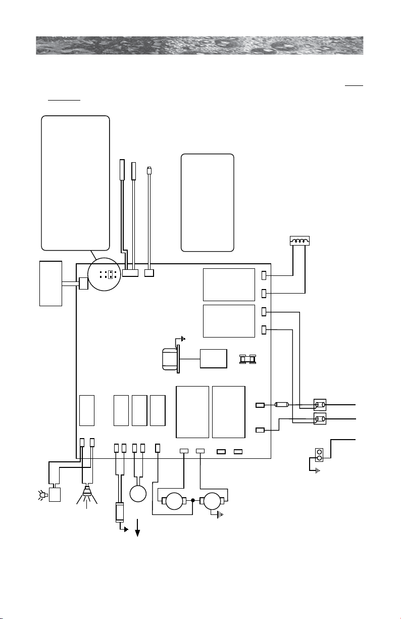
680 SERIES
Ozonator (optional )
GRN
TB1
Standard 240 VAC, 3-Wire Connection (60Hz, 1-Phase Service)
USE COPPER CONDUCTORS ONLY. WIRE SIZE MUST
BE APPROPRIATE PER NEC AND/OR LOCAL CODES
RED
RED
J6
BLK
J5
WHT
WHT
RED
BLK
BLK
RED RED
BLK BLK
2
1
Pressure switch
Hi - limit / freeze sensor
Temperature sensor
J1
J2
J3
F1
30A, 250V
SC-30
Pump 1
Transformer
240 VAC
J4
F1
JP1
4
2
3
1
6 5
8 7
HI
LO
Control Panel
J20
K1
K2
K3
K4
K5
K6 K7 K8
J21
J11
J12
J13
J14
J15
J16
J17
J18
J19
J7
J8
J9
J10
This device complies with Part 15 of the
FCC rules. Operation is subject to the
following two conditions:
1. This device may not cause harmful
interference.
2. This device must accept any inteference
received including interference that may
cause undesired operation.
Heater
5.5 kW
240 VAC
WHT
BLK
WHT
BLK
Standard
Footwell
Light
Optional
LED Lighting
System DCU
OR
WHT
BLK
C
Circ.
Pump
BLK
Logic Jumper Settings (Factory Defaults Shown)
JP1 1-2 ON = 40A Logic
JP1 1-2 OFF = 50A Logic (Factory Default Setting
JP1 3-4 ON = 2 Pump Operation
JP1 3-4 OFF = 1 Pump Operation
JP1 5-6 ON = Not Used
JP1 5-6 OFF = Not Used
JP1 7-8 ON = °C Temperature Display
JP1 7-8 OFF = °F Temperature Display
16.0 North American Burlington Models (60 Hz)
This wiring diagram is used for all North American Burlington models with
or without the circulation pump option.
Circuit Board
diagram
shown with
circulation
pump option.
Page 41
Page 48
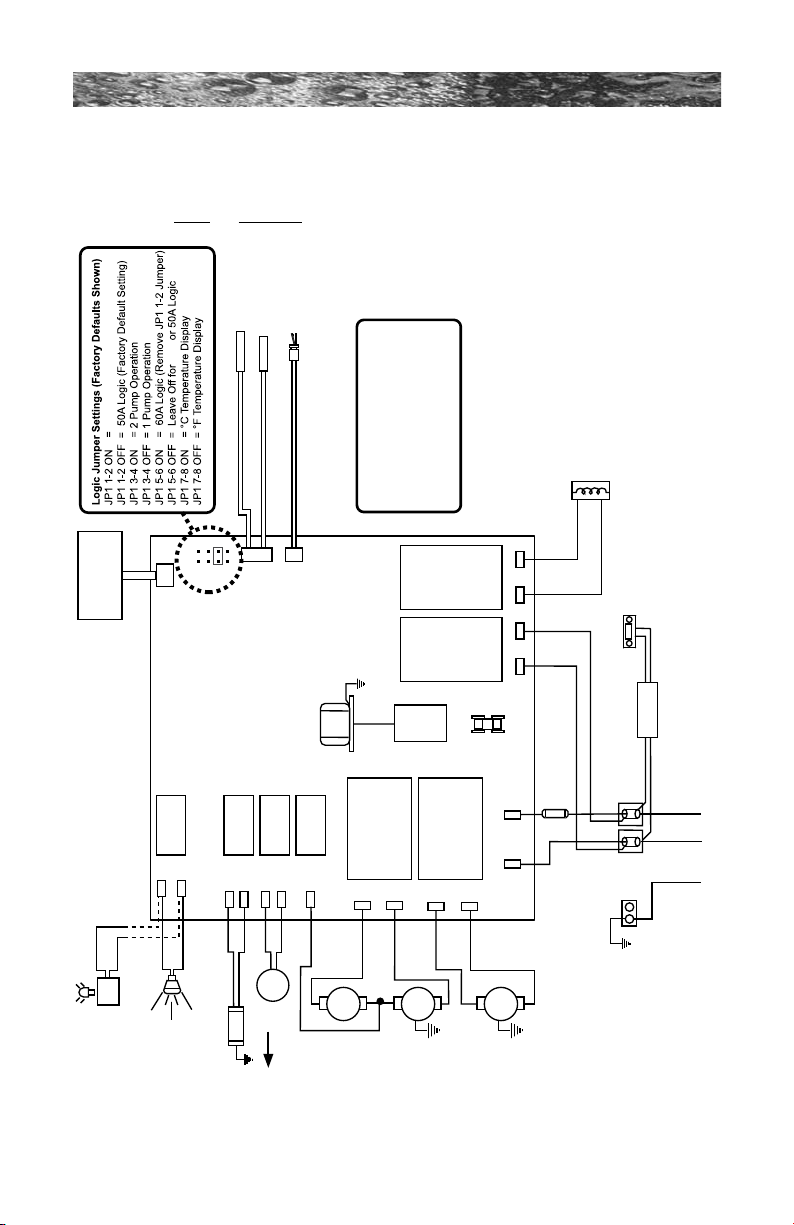
680 SERIES
Optional
Stereo
Power Supply
Ozonator (optional )
O
3
GRN
TB1
Standard 240 VAC, 3-Wire Connection (60Hz, 1-Phase Service)
USE COPPER CONDUCTORS ONLY. WIRE SIZE MUST
BE APPROPRIATE PER NEC AND/OR LOCAL CODES
RED
RED
J6
BLK
J5
WHT
WHT
WHT
RED
BLK
BLK
BLK
WHT
BLK
RED RED
BLK BLK
BLK
2
1
Flow switch
Hi - limit / freeze sensor
Temperature sensor
J1
J2
J3
F1
30A, 250V
SC-30
Pump 1
Pump 2
Transformer
240 VAC
J4
F1
JP1
4
2
3
1
6 5
8 7
7 6 2 4
HI
HI
LO
C
Control Panel
Circ.
Pump
J20
K1
K2
K3
K4
K5
K6 K7 K8
J21
J11
J12
J13
J14
J15
J16
J17
J18
J19
J7 J8
J9
J10
This device complies with Part 15 of the
FCC rules. Operation is subject to the
following two conditions:
1. This device may not cause harmful
interference.
2. This device must accept any inteference
received including interference that may
cause undesired operation.
Heater
5.5 kW
240 VAC
40A Logic
40A
WHT
BLK
WHT
BLK
Standard
Footwell
Light
Optional
LED Lighting
System DCU
OR
17.0 North American Hartford and Hawthorne Models (60
Hz)
This wiring diagram is used for all North American Hartford and
Hawthorne with or without the circulation pump option.
Page 42
Circuit Board
diagram
shown with
circulation
pump option.
Page 49
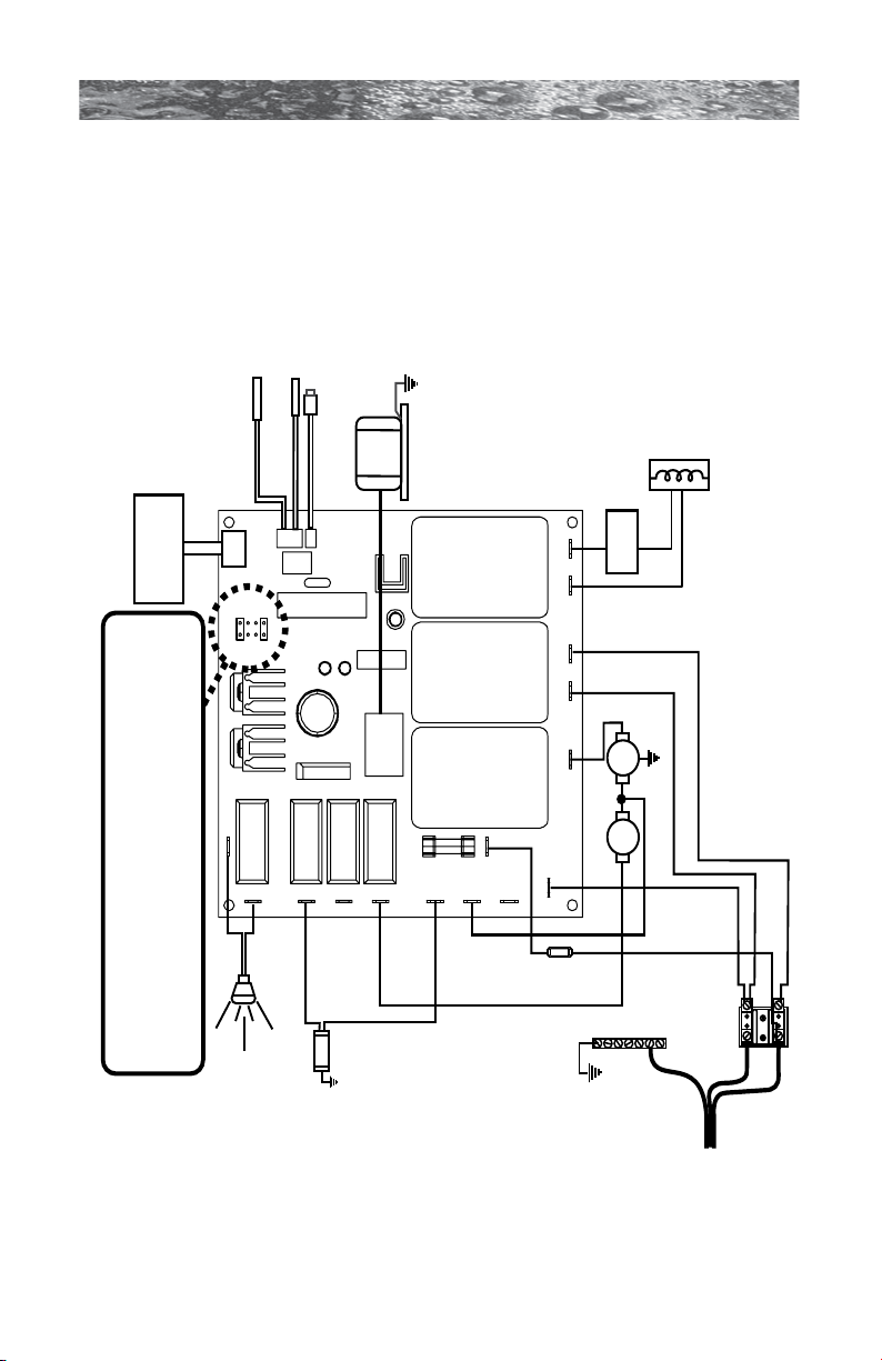
680 SERIES
Standard 3-Wire 230 VAC Connection (50 Hz, 1 Phase Service)
Use copper conductors ONLY. Wire size must be appropriate per NEC and/or
local codes.
BLK
BLK
BLU
BLU
BLU
BLU
BLU
BLU
BRN
BRN
BRN
BRN
BRN
BRN
BRN
Heater
2.7kW @ 230 VAC
Pressure Switch
Hi-limit/Freeze Sensor
Temperature Sensor
J2
J3
Spa Light
Transformer
230 VAC
J1 Logic Jumper Settings
JP1 1-2 ON = 20A Logic (Factory Setting)
JP1 1-2 OFF = 30A Logic
JP1 7-8 ON = °C Temperature Display (Factory Setting)
JP1 7-8 OFF = °F Temperature Display
J20
J21
J12
J14
J16
J11
J15
J13
J17 J7 J8
J9
J10
J5
J6
Heater IN Heater OUT
F1*
K5 K7 K8
J1
Control
Panel
THERM
SWITCH
753
1
864
2
Standard
Ozonator
O
3
F1
20A
250V
SC-20
GRN
TB1
BLU
BRN
1
2
GROUND
Main Pump
HILO
Hard
Wire
Only
18.0 Export Denali/Tacoma Circuit Diagram (50 Hz)
This wiring diagram is used for all Export Denali/Tacoma models.
Page 43
Page 50
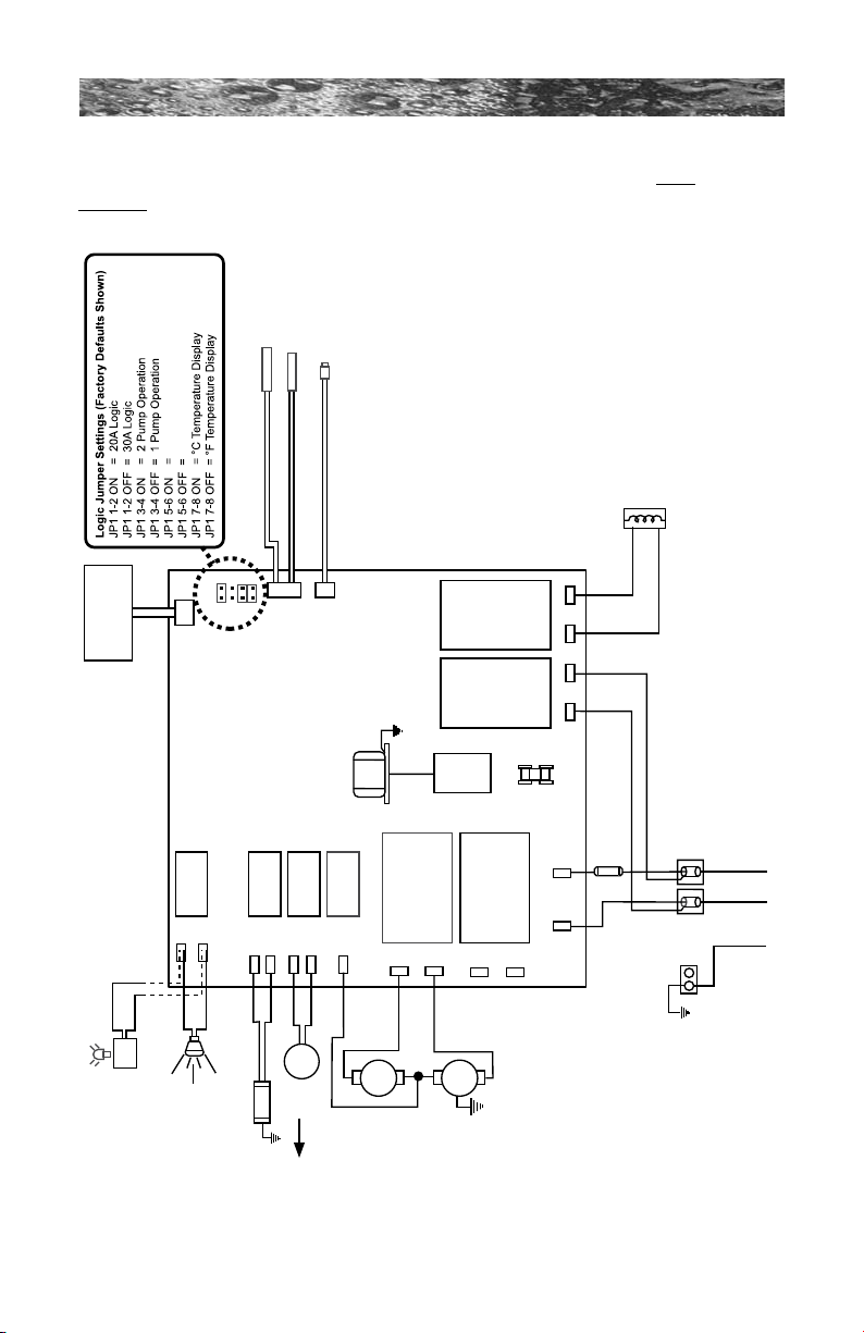
680 SERIES
Ozonator (standard )
O
3
GRN
TB1
230 VAC 3-Wire Connection (50Hz, 1-Phase Service)
USE COPPER CONDUCTORS ONLY. WIRE SIZE MUST BE
APPROPRIATE PER NEC AND/OR LOCAL CODES
BLU
BLU
J6
BRN
J5
BRN
BLU
BLK
BLU
BRN
BLU BLU
BRN BRN
BRN
2
1
Pressure switch
Hi - limit / freeze sensor
Temperature sensor
J1
J2
J3
F1
20A, 250V
SC-20
Pump 1
Transformer
240 vac
J4
F1
JP1
4
2
3
1
6 5
8 7
HI
LO
Control Panel
J20
K1
K2
K3
K4
K5
K6 K7 K8
J21
J11
J12
J13
J14
J15
J16
J17
J18
J19
J7 J8
J9
J10
Heater
2.7 kW @
230 VAC
WHT
BLK
WHT
BLK
Standard
Footwell
Light
Optional
LED Lighting
System DCU
OR
Not Used
Not Used
WHT
BLK
C
Circ.
Pump
19.0 Export Burlington Circuit Diagram (50 Hz)
This wiring diagram is used for all Export Burlington models with or
without the circulation pump option.
Page 44
Circuit Board
diagram
shown with
circulation
pump option.
Page 51
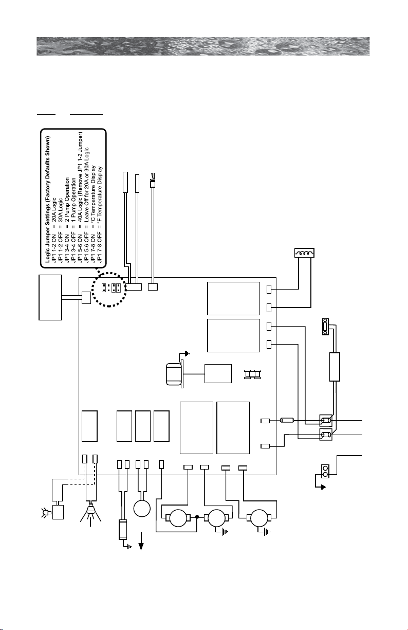
680 SERIES
STEREO
(Optional)
Power Supply
Ozonator (standard )
O
3
GRN
TB1
230 VAC 3-Wire Connection (50Hz, 1-Phase Service)
USE COPPER CONDUCTORS ONLY. WIRE SIZE MUST BE
APPROPRIATE PER NEC AND/OR LOCAL CODES
BLU
BLU
J6
BRN
J5
BRN
BRN
BLU
BLK
BLU
BLU
BRN
BLU
BRN
BLU BLU
BRN BRN
BRN
2
1
Flow switch
Hi - limit / freeze sensor
Temperature sensor
J1
J2
J3
F1
20A, 250V
SC-20
Pump 1
Pump 2
Transformer
240 VAC
J4
F1
JP1
4
2
3
1
6 5
8 7
HI
HI
LO
C
Control Panel
Circ.
Pump
J20
K1
K2
K3
K4
K5
K6 K7 K8
J21
J11
J12
J13
J14
J15
J16
J17
J18
J19
J7 J8
J9
J10
Heater
2.7 kW @
230 VAC
WHT
BLK
WHT
BLK
Standard
Footwell
Light
Optional
LED Lighting
System DCU
OR
20.0 Export Hartford and Hawthorne Circuit Diagram
(50 Hz)
This wiring diagram is used for all Export Hartford and Hawthorne models
with or without the circulation pump option.
Page 45
Circuit Board
diagram
shown with
circulation
pump option.
Page 52
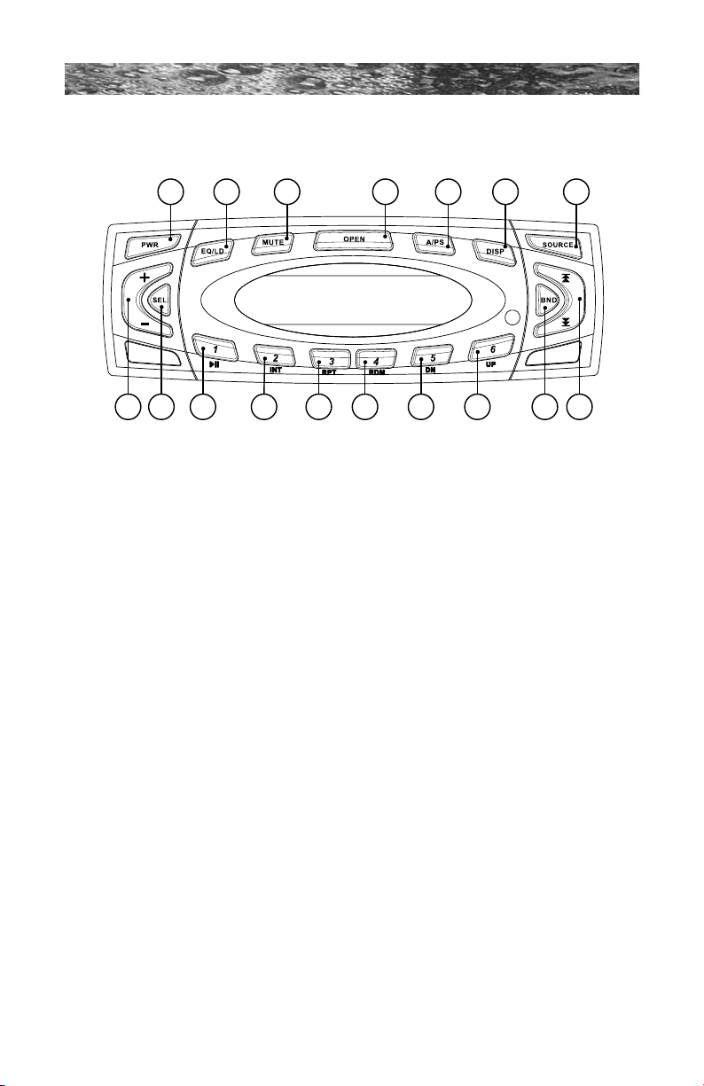
680 SERIES
1
8 9 10 11 12 13 14 15 16 17
2 3 4 5 6 7
21.0 Optional SunSoundTM Stereo Receiver Functions
(Burlington, Hartford and Hawthorne Models Only)
To start enjoying your new Sundance SunSound Stereo Receiver, please
read the following operation instructions in their entirety.
1. Power Button: Press PWR (Power) to turn deck on or off.
2. Equalization Button: Repeatedly press EQ/LD to choose from DSP
Off, Jazz, Pop, Classic, Rock or Vocal equalization options. Press
and hold EQ/LD for 2 seconds to enable or disable the “LOUD”
function.
3. Mute Button: Press Mute to mute audio output. Press again to
return to previous volume level.
4. Open Button: Press Open to ip down the front access panel for CD
access. Gently insert CD into slot, DO NOT FORCE! Make sure to
close the front panel to prevent damage to the unit.
Note: Never insert a wet or moist CD since it may damage the
mechanism and void the manufacturer warranty.
5. A/PS Button: Press A/PS to scan station presets. The tuner will scan
6. DISP Button: Press DISP to switch between clock and station
Page 46
up, wait for a few seconds, then continue. Once a desired station is
found, press A/PS a second time to cancel scan. To automatically
scan and store station presets, simply press and hold A/PS for
several seconds, then release.
frequency. When selected, the clock will display for 5 seconds then
automatically revert back to station frequency.
Page 53

680 SERIES
7. Source Button: Press Source to change input from audio or CD
mode to auxiliary mode. Press a second time to switch back.
8. Volume Buttons: Press + (Volume Up) or - (Volume Down) to
increase or decrease volume level.
9. SEL Button: Press SEL to choose control function:
• Bass
• Treble
• Balance
• Fader
• Volume
To adjust selection, press + (Volume Up) or - (Volume Down). Bass
control: Adjusts the amount of low frequency. Treble control: Adjusts
the amount of high frequency. Balance control adjusts the amount
of sound output to the left and right speakers. Fader control adjusts
the amount of sound output. You can decrease the sound level of the
rear speakers by pressing + (Volume Up). To decrease the sound
level of the front speakers press - (Volume Down).
Note: Bass and Treble settings are available only if EQ is set to DSP Off.
10. Preset 1/Pause Play Button: In tuner mode, any station can be
stored as preset 1 by pressing and holding this button for 2 seconds.
To recall the station preset, simply press and release this button. In
CD mode pressing this button will pause or play the CD.
11. Preset 2/INT Button: In tuner mode, any station can be stored as
preset 2 by simply pressing and holding this button for 2 seconds.
To recall the station preset, simply press and release this button. In
CD mode pressing this button will preview each song on the disc for
about 10 seconds. Simply press again to turn off this feature.
12. Preset 3/RPT Button: In tuner mode, any station can be stored
as preset 3 by simply pressing and holding this button for several
seconds. To recall the station preset, simply press and release this
button. In CD mode pressing this button will play a song repeatedly.
Press again to turn off this feature.
13. Preset 4/RDM Button: In tuner mode, any station can be stored
as preset 4 by simply pressing and holding this button for several
seconds. To recall the station preset, simply press and release this
button. In CD mode press this button to randomly play song tracks.
Press again to turn off this feature.
Page 47
Page 54
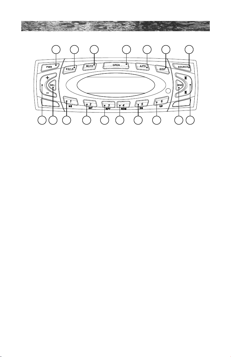
680 SERIES
1
8 9 10 11 12 13 14 15 16 17
2 3 4 5 6 7
14. Preset 5/DN Button: In tuner mode, any station can be stored
as preset 5 by simply pressing and holding this button for several
seconds. To recall the station preset, simply press and release this
button. In CD mode this button will browse the folders on CD-R and
CD-RW disks.
15. Preset 6/UP Button: In tuner mode, any station can be stored
as preset 6 by simply pressing and holding this button for several
seconds. To recall the station preset, simply press and release this
button. In CD mode this button will browse the folders on CD-R and
CD-RW disks.
16. BND Button: Press BND to select one of the following frequency
bands: FM1, FM2, FM3, AM1, AM2 and WB (weather band).
17. Tuning UP/DOWN Buttons: Press Track Up to manually adjust
station frequency up. Press and hold Track Up to scan for next
higher station. Scan mode stops as soon as a strong station is found.
Press Track Down to manually adjust frequency down. Press and
hold Track Down to scan for next lower station. Scan mode stops as
soon as a strong station is found. In CD mode pressing these buttons
will advance the CD up or down to the next or previous track. To
fast forward or rewind through a track, simply press and hold either
18. Reset Button (Not Illustrated): If keys do not function at all and the
Note: This action will reset the display and clock to default settings.
Page 48
button as desired during CD playback.
unit appears to be "locked up", use a ballpoint pen to press the Reset
Button under the front panel (press OPEN to ip down front panel for
access). The Reset button is located directly below the Eject Button.
Press to clear all memory (except station presets) and reset deck.
Page 55

680 SERIES
19. Eject Button (Not Illustrated): To eject CD, press OPEN and ipdown the front access panel, then press the Eject button located to
the left of CD slot.
20. USA/Europe Switch (Not Illustrated): You can switch between
American (USA) and European radio frequency bands by ipping a
switch located on the bottom of the deck. To change bands:
1) Power down unit
2) Lift up sticker under the CD player.
3) Choose desired frequency band as indicated on the sticker.
4) Put sticker back in place and power up the unit.
21. Setting The Clock (Unit Must be Off): To set the current time, press
and hold Display (6) for 3 seconds until the clock display starts to
blink, then set hours using the Track Up and/or Track Down button
(17). Press Display a second time to set minutes, using the Track Up
and/or Track Down buttons. Press and hold Display a third time to
exit clock setup (or simply wait for 5 seconds).
22. Selecting Weather Band Mode: Press BND (16) while in tuner
mode until WB displays (deck automatically skips to the strongest
weather channel) or press BND a second time to return to previous
mode. When WB weather band mode is active:
• Press Track Up (17) to scan to higher weather channel.
• Press Track Down (17) to scan to lower weather channel.
• To save a weather channel preset, press and hold one of six
numeric keys 1-6.
Note: Weather channel 7 is not accessible through preset key.
23. Display information DISP:
When a retail music CD is inserted, press DISP (6) to change modes
as follows:
• Clock (displays for 5 seconds only).
• CD track no./Playtime
When a CD containing MP3 les is inserted, press DISP (6) change
modes as follows:
• Clock (displays for 5 seconds only).
• Track no./Playtime
• Folder name
• File name
• Song name
• Artist’s name
• Album name
Page 49
Page 56
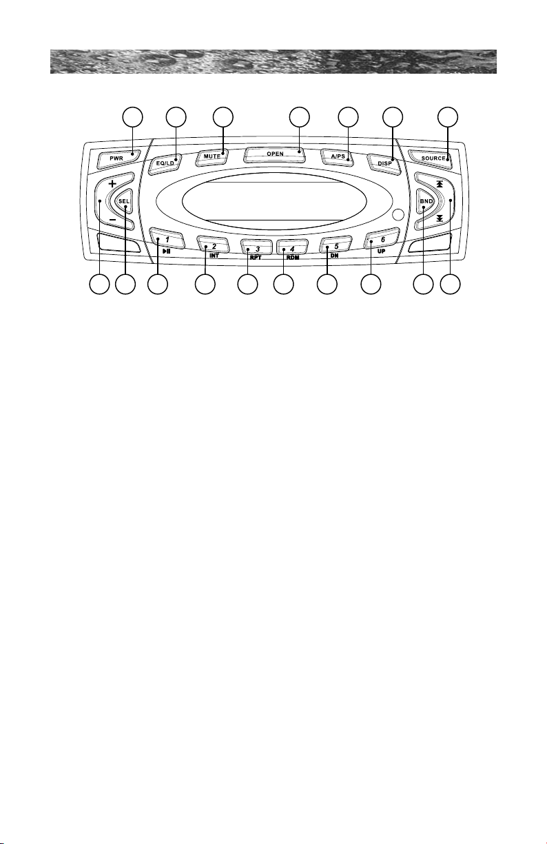
680 SERIES
1
8 9 10 11 12 13 14 15 16 17
2 3 4 5 6 7
The system can only display the rst 8 letters of ID3 tags. If the
recorded information is longer than 8 letters, text will scroll to the left
once, then the 8 rst letters will be displayed. If specic info has not
been recorded on an MP3 disc, NO FOLD, NO TRK, NO TLT, NO
ALBM, NO ART will display.
24. Playback Order of The MP3 File:
• A directory that does not include an MP3 le is skipped.
• We recommend that you make no more than two levels for each
disc.
• Maximum number of folders: 256
• Maximum number of folder levels: 8
• Maximum number of characters for MP3 le name and folder
name: 32
• Sampling frequency: 16 kHz, 22.05 kHz, 24 kHz, 32 kHz, 44.1
kHz, 48kHz
• Bit rates: 8-320 Kbps
• MP3 decoding format: MPEG 1 & 2 Audio Layer 3
• Folder names and le names can be displayed with up to 8
characters (see Display key).
• The characters A-Z, 0-9 can be displayed on this unit, other
characters may not be displayed correctly.
• ID3 tag is supported (see Display key).
25. Readinglesintoadisc: When a disc containing MP3 data is
loaded, the unit checks all the data on the disc. If the disc contains
numerous folders with many levels, it takes a longer time to start
playback. In addition, it may take time for the unit to move to the
Page 50
Page 57

680 SERIES
next MP3 le and the fast forward function may not be performed
smoothly. When selected to play, les and folders are accessed in
order in which they were written by the CD writer. Therefore, the
playing order may not be the same as the order in which they are
expected. For example, a disc with the following folder/le hierarchy
is subject to folder select, le select and playback order as illustrated
on page 52.
TM
21.1 Optional SunSound
Audio Receiver Specifications
• Marine Grade AM/FM/CD/CD-R/CD-RW/MP-3
• 7 Bands of Weather Band
• Stainless Steel Sealed Chassis and Mounting Hardware
• IPX5 Water Intrusion & CFR-46 Rated
• Conformal Coated Printed Circuit Boards
• ASTMB117 Salt Fog Tested 400 Hours
• ASTM D4329 UV Stable Tested 400 Hours
• Double Sealed Water Protection Transport Gaskets
• White Low Current/Low Heat LCD
• White Backlit Control Surfaces
• 5 Band Digital Sound Stage Settings
• 200 Watt, 50 x 4
• MP3 with ID-3 Tag, Video
• Switchable Tuner Frequency U.S. or Euro Band/CE Approved
Page 51
Page 58
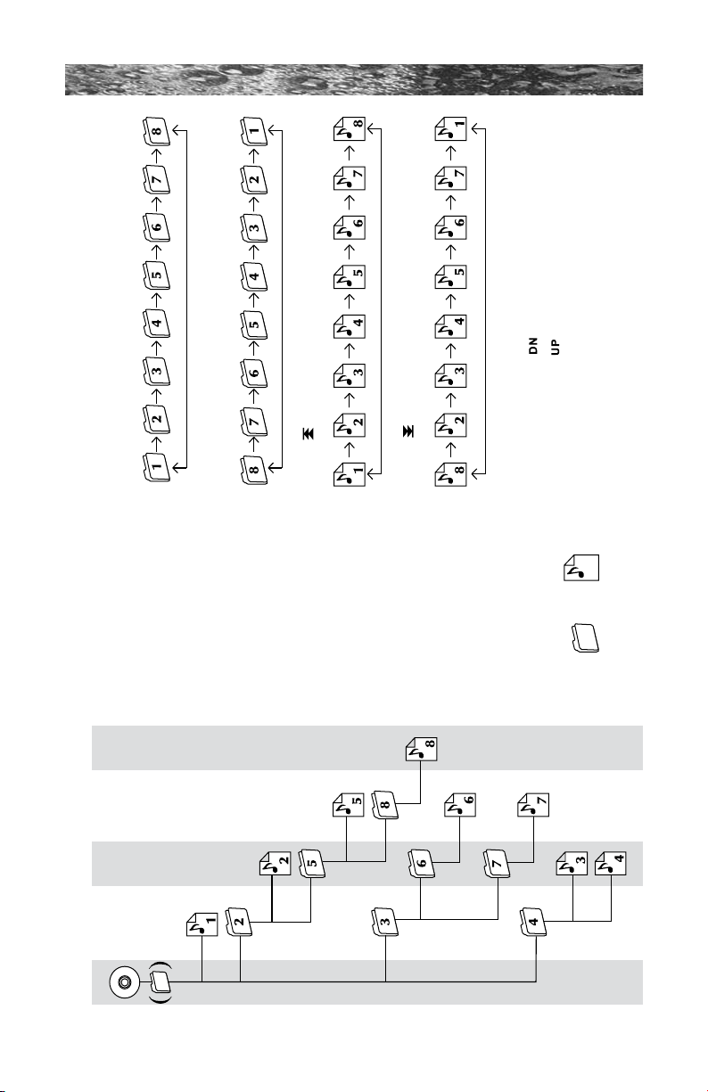
680 SERIES
Press and hold to go 10 files forward.
Example of a disc's folder/file hierarchy
Folder
File
Level 1 Level 2 Level 3 Level 4 Level 5
Operation of the keys
Press and hold to return 10 files behind.
Press (Track Down) to select folder down
Press (Track UP) to select folder up
5
6
Page 52
Page 59

Notes:
680 SERIES
Page 53
Page 60

680 SERIES
Notes:
 Loading...