


Operator’s Manual
Model SB-5570HD
Model SB-6570HD
Revision 339-140617
PN: M55-065-00
Important Safety Instructions
Dear SunBriteTV Customer:
Congratulations on the ownership of your SunBriteTV all-weather outdoor LCD TV, and welcome to the family of satisfied SunBrite customers. You are in great company, with thousands of homeowners and esteemed commercial facilities such as Yankee Stadium, Fenway Park, Disney World, and Sea World who have trusted us to deliver superior performance, lasting durability and the enjoyment of superb television viewing in the great outdoors.
Our products are designed to withstand the rigors of the outdoor environment and provide our customers with many years of optimum viewing, while delivering excellent picture and sound as well as the ease of use and convenience of conventional indoor TVs.
To ensure safety and long product life, please read the Important Safety Instructions and complete manual carefully before using the TV. If you have any questions about the installation procedures, please contact our qualified SunBriteTV Customer Support Team at 800.331.4626.
IMPORTANT SAFETY INSTRUCTIONS
1)Read these instructions, and keep them for future use.
2)Heed all warnings and follow all instructions.
3)Do not block any ventilation openings. Install in accordance with the manufacturer’s instructions.
4)Do not install near any heat sources such as radiators, heat registers, stoves, or other apparatus (including amplifiers) that produce heat.
5)Do not defeat the safety purpose of the polarized or grounding-type plug. A polarized plug has two blades with one wider than the other. A grounding type plug has two blades and a third grounding prong. The wide blade or the third prong are provided for your safety. If the provided plug does not fit into your outlet, consult an electrician for replacement of the obsolete outlet.
6)Protect the power cord from being walked on or pinched, particularly at plugs, convenience receptacles, and the point where the cord exits from the apparatus.
7)Only use attachments/accessories specified by the manufacturer.
8)Use only the cart, stand, tripod, bracket or table specified by the manufacturer, or
sold with the apparatus. When a cart is used, use caution when moving the cart/apparatus combination to avoid injury from tip-over.
9)Unplug this apparatus during lightning storms.
10)Refer all servicing to qualified service personnel. Servicing is required when the apparatus has been damaged in any way, such as power-supply cord or plug is damaged, liquid has been spilled or objects have fallen into the apparatus, does not operate normally, or has been dropped.
WARNING: TV must be plugged into a GFCI receptacle.
TV and GFCI RECEPTACLE MUST BE INSTALLED NO LESS THAN 5 FEET FROM ANY BODY OF WATER (SUCH AS POOL OR SPA). Check local building codes for proper installation guidelines.
WARNING: This unit is equipped with a 3-pin grounded plug. The plug will only fit into a grounded power outlet. This is a safety feature. If you are unable to insert the plug into the outlet, contact your electrician. Do not alter this plug, as this will defeat the safety feature.
WARNING: The main plug is used as the disconnect device and shall remain readily operable.
WARNING: This product shall be connected to a mains socket outlet with a protective earthing connection.
CAUTION: TO PREVENT ELECTRIC SHOCK, MATCH WIDE BLADE OF PLUG TO WIDE SLOT, FULLY INSERT.
WARNING: FCC Regulations state that any unauthorized changes or modifications to this equipment not expressly approved by the manufacturer could void the user’s authority to operate this equipment.
NOTE TO CATV SYSTEM INSTALLER: This reminder is provided to call the CATV system installer’s attention to Article 820-40 of the National Electrical Code that provides guidelines for proper grounding and, in particular, specifies that the cable ground shall be connected to the grounding system of the building, as close to the point of cable entry as practical.
WARNING: To reduce the risk of fire or electric shock, do not expose the inside of this apparatus to rain or moisture.
This product utilizes tin-lead solder.. Disposal of these materials may be regulated due to environmental considerations. For disposal or recycling information, please contact your local authorities or the Electronic Industries Alliance: www.eia.org.
Disclaimer: While SunBriteTV LLC intends to make this manual accurate and complete, we do not make claims that the information contained within covers all details, conditions or variations, nor does it provide for every possible contingency in connection with the installation or use of this product. The information contained in this manual may change without notice.
Page 2 |
All Rights Reserved. 2014 ©SunBriteTV® LLC |

Important Safety Instructions
Cleaning Instructions: See “Care of SunBriteTV” on page 36.
Attachments: Do not use attachments not specifically recommended by the manufacturer. Use of improper attachments can result in accidents.
Power Source: SunBriteTV must operate on a power source indicated on the specification label. If you are not sure of the type of power supply used in your home, consult your dealer or local power company. When using the TV outdoors, you must use a GFIprotected AC outlet with “in-use” waterproof cover.
Installation: Do not place the product on an unstable cart, stand, tripod, table, or anywhere the unit is not permanently installed. Placing the product on an unstable place can cause the product to fall, resulting in potential serious personal injuries, as well as damage to the product.
Precautions when Transporting the TV: Carrying the television requires at least two people.
FCC Statement
This equipment complies with the limits for a Class B digital device, pursuant to part 15 of the FCC Rules. These limits are designed to
provide reasonable protection against harmful interference in a residential installation. This equipment generates, uses, and can radiate radio frequency energy and, if not installed and used in accordance with the instructions, may cause harmful interference to radio communications. However, there is no guarantee that interference will not occur in a particular installation. If this equipment does cause harmful interference
to radio or television reception, which can be determined by turning the equipment off and on, the user is encouraged to try to correct the interference by one or more of the following measures:
1. Reorient or relocate the receiving antenna.
2. Increase the separation between the equipment and receiver.
3. Connect the equipment into an outlet on a circuit different from that to which the receiver is connected.
4. Consult the dealer or an experienced radio/TV technician for help.
Modifications not expressly approved by the manufacturer could void the user’s authority to operate the equipment under FCC rules.
This device complies with part 15 of the FCC Rules. Operation is subject to the following two conditions:
1. This device may not cause harmful interference.
2. This device must accept any interference received, including interference that may cause undesired operation.
SunBriteTV Model 5570HD and 6570HD Operator’s Manual |
Page 3 |

Important Safety Instructions
Ventilation: Adequate ventilation must be maintained to ensure reliable and continued operation and to protect the television from overheating. There must be at least 1.5” of space on all sides.
Power cord protection: The power cord must be routed properly to prevent people from stepping on it, or objects from resting on it. Check the cords at the plugs and product.
Power source: This product must operate on a power source specified on the specification label. If you are unsure of the type of power supply used in your home, consult your dealer or local power company.
Do not let metal pieces or objects of any kind fall into the television from ventilation holes. High voltage flows in the product, and inserting an object can cause electric shock and/or short internal parts.
Do not mount SunBriteTV near a motor or transformer where strong magnetism is generated. Images on the television will become distorted and the color irregular.
Do not mount SunBriteTV near heat sources such as radiators, heaters, stoves and other heat-generating products (including amplifiers).
Do not submerge SunBriteTV in water: The SunBriteTV will resist water exposure from normal rain, sprinklers, garden hoses, etc.; however, it is not designed to be submerged in water.
Do not pressure-wash SunBriteTV: SunBriteTV will resist water exposure from normal rain, sprinklers, garden hoses, etc.; However, it is not designed to withstand pressure washers, high-pressure water jets, or hurricane-type weather.
Do not service SunBriteTV yourself: Removal of the television screen cover may expose you to high voltage or other dangerous risks. Refer all servicing to a qualified service professional. Warranty will not be honored if you service the unit yourself.
Repair: If any of the following conditions occurs, unplug the power cord, and call a qualified service professional to perform repairs:
When power cord or plug is damaged. When objects have fallen into the product.
If unit was submerged in water or pressure-washed.
When product does not operate properly as described in the operating instructions. Do not touch the controls other than as described in the operating instructions. Improper adjustments of controls not described in the
instructions can cause damage, which can require extensive repair work by a qualified technician. When the product has been dropped or damaged.
When the product displays an abnormal condition. Any noticeable abnormality in the product indicates that the product needs servicing.
Replacement parts: In case the product needs replacement parts, make sure that the service person uses replacement parts provided by SunBriteTV. Use of unauthorized parts can result in fire, electric shock and/or other danger.
Safety checks: Upon completion of service or repair work, ask the service technician to perform safety checks to ensure that the product is in proper operating condition.
Page 4

Table of Contents
Important Safety Instructions |
2 |
Table of Contents |
5 |
Supplied Accessories |
6 |
TV Installation |
|
Choosing a Location/Speaker Installation |
6-7 |
Rear Panel Internal Connect Source |
8 |
Rear Panel Connection Diagrams |
9 |
IR Emitter Installation |
17 |
Side Panel and Front Panel Controls |
18 |
Remote Control Guide |
19 |
On-Screen Display Controls |
21 |
Adjusting On-Screen Displays |
|
Channel Menu |
23 |
Picture Menu |
25 |
Audio Menu |
26 |
Time Menu |
27 |
Setup Menu |
28 |
Lock Menu |
31 |
Using the USB Input / Menu |
34 |
Troubleshooting |
35 |
Care of SunBriteTV |
36 |
Specifications |
37 |
Features Information and Instructions |
39 |
Extreme Climate Warning |
39 |
Programming Other Manufacturers’ Universal Remote Control Devices |
39 |
SunBriteTV Pixel Quality Policy |
39 |
Appendix A - RS232 Cable Pinout |
40 |
Appendix B - RS232 Control Codes |
41 |
SunBriteTV Model 5570HD and 6570HD Operator’s Manual |
Page 5 |
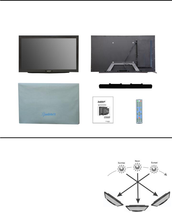
Supplied Accessories
Unpacking
After unpacking the SunBriteTV television, please make sure that the following items are included in the carton and that they are in good condition. If items are damaged or missing, contact your dealer immediately.
SunBriteTV LCD Television |
Speaker Module |
Dust Cover |
Remote Control with Batteries |
Operator’s Manual |
|
Model 5570HD or 6570HD front view |
Rear View - 5570 Pictured with |
|
shown with optional table top stand (not included) |
optional table top stand (not included) |
|
|
|
Speaker Module |
|
|
|
|
|
|
Outdoor Dust Cover |
Operator’s Manual |
Remote Control |
TV Installation - Choose a Location for the TV
Choose a Location for the TV
Important: The TV must be installed at least 5 feet from pool, spa, or other body of water.
The TV should be installed so the screen is not facing direct sunlight, or can be easily turned away from direct sunlight.
Ideal placement is in an area where the TV is shaded by trees, landscape and/ or structures, or under a patio cover or gazebo.
Remember that the position of the sun changes during the day, as seen in the drawing at right., This means that the quality of the picture will change during the day. If you intend to install the TV in areas where direct sunlight will reach it, it’s best to postion the TV for optimum performance during the time of day when you do most of your TV watching.
If the sun shines directly on the screen for long periods of time, dark areas may develop on the screen. This is a normal reaction for the LCD panel, and will not cause damage to the screen. Either turn the screen away from the sun, or apply shade to the TV, and the dark areas will quickly disappear.
Page 6
TV Installation - Detachable Speaker Module Installation
Detachable Speaker Module Installation
Tools Needed: Phillips screwdriver
Note:
If you mount the TV to a ceiling or wall mount, it is best to install the Detachable Speaker Module in the top or bottom mount position after the TV has been installed.
1. Remove the two 8-32 surface mount screws(figure 2) in either the top or bottom mount position(figure 1). Do not remove the recessed screws for mounting the speaker. (figure 3)
WARNING: Use at least two people when transporting the TV.
2. Position the Speaker bar in place and secure with two 8-32 screws removed in step 1. (Figure 4)
Important Note: Always replace mounting screws. Failure to do so will allow water to seep inside your TV. This can cause serious injury and damage your TV.
3.Screw securely
4.Loosen the two thumb screws, and open the Connect Source Cover.
5.Take the Speaker Cable from the speaker, making sure that the Speaker Cable Wire is placed on the Rubber Sealing Gasket (Figure 5), and plug it into the Speaker Connector.
6.When you close the Connect Source Cover, be sure that the Speaker Cable Wire is placed across the Rubber Sealing Gasket.
As with all wires entering the connection compartment, leave a drip loop as the wire enters the TV, this will allow water to drip from the bottom of the loop.(Figure 6).
Figure 2 |
Figure 3 |
Surface screws |
Recessed screws |
Use to mount Speaker |
Do not remove |
Figure 4
Mount speaker using two 8-32 screws
Drip Loop
Figure 5 |
Figure 6 |
Speaker Connector
SunBriteTV Model 5570HD and 6570HD Operator’s Manual |
Page 7 |
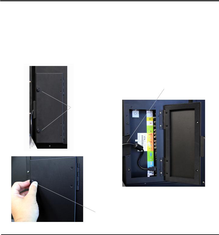
TV Installation – Rear Panel Internal Connect Source
WARNING: Do not connect the power source before making connections.
Internal Connect Source
The Internal Connect Source allows you to easily connect to the Audio, Video, S-Video, SVGA, HDMI, Audio Out, and RF connectors. The Internal Connect Source is inside the Cable Cover located on the back of the unit (Figure1).
1.Unscrew the two Thumb Screws (Figure1), and pull the cover towards you.
2.Route the cables to the proper inputs, and place the cable cords over the Rubber Sealing Gasket (Figure 2).
3.Close the cover.
4.Press firmly on the cover, and screw the Thumb Screws tightly (Figure3).
Figure 1 |
Figure 2 |
Rubber Sealing Gasket |
Thumb Screws
Figure 3
Thumb Screw
TV Installation - Connecting the Power Cord
Do not connect power cord until all cable connections have been made.
Connect the power cord to a GFCI protected AC outlet with an “in-use” waterproof cover.
WARNING:
TV AND GFCI RECEPTACLE MUST BE INSTALLED AT LEAST 5 FEET AWAY FROM STANDING WATER , SUCH AS (BUT NOT LIMITED TO) A POOL OR SPA. BE SURE TO CHECK LOCAL ELECTRICAL CODES AND COMPLY WITH THEIR LOCAL STANDARDS.
Page 8
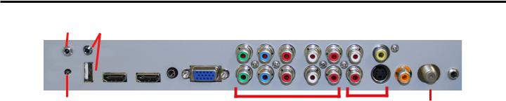
TV Installation – Rear Panel Connections
Connections
1 |
3 |
4 |
5 |
6 |
7 |
9 |
10 |
11 |
13 |
|||||||
|
|
|
|
|
|
|
|
|
|
|
|
|
|
|
|
|
|
|
|
|
|
|
|
|
|
|
|
|
|
|
|
|
|
|
|
|
|
|
|
|
|
|
|
|
|
|
|
|
|
|
|
|
|
|
|
|
|
|
|
|
|
|
|
|
|
|
|
2 |
8 |
10 |
12 |
1.RS232 - For remote control using RS232 commands
2.IR WINDOW - For remote control using IR commands.
3.SERVICE PORT - These USB and high speed serial ports are for factory service only...DO NOT USE
4.HDMI 1 - Connects to devices that use HDMI cables such as Blu-ray or HD DVD player or HD cable / satellite set-top box. This connection port receives pure digital audio and high definition signal through one single cable. This port also can accept a HDCP video device for video or PC for monitor display usage. Use the SOURCE button to select HDMI1 on your MAIN SOURCE to view this connection. Please note: when using HDMI, your sound signal must be PCM for the TV to decode digital audio. When using this source for PC display, you must connect the audio cable to VGA Stereo Input for audio.
5.HDMI 2 - Same as HDMI 1
6.VGA STEREO INPUT - This connection port is for people who want to provide audio to the TV when using a PC or a DVI video device. Use a 3.5mm mini-jack audio cable (headphone jack) to provide audio for a HDCP enabled DVI video device or PCs with VGA or DVI connection.
7.VGA - This connection port connects to a PC for video using VGA cable. Be sure to connect your audio cable to the VGA Stereo input if you want sound out of the VGA video source. Use the SOURCE button to select VGA on your MAIN SOURCE to view this connection.
8.COMPONENT 1 (Lower) - This connection ports are for DVD players or satellite/cable set-top boxes that use component cables. From left to right, connect green, blue and red for video, and then connect white for left channel audio, red for right channel audio. Use the Source Button to select YPbPr1 to review this connection.
9.COMPONENT 2 (Upper) - his connection ports are for DVD players or satellite/cable set-top boxes that use component cables. From left to right, connect green, blue and red for video, and then connect white for left channel audio, red for right channel audio. Use the Source Button to select YPbPr2 to review this connection.
10.AV 1 (CVBS or S-Video) - Connects to devices that use composite or s-video cables such as VCR or camcorder or video game consoles. Connect the video portion with either the yellow connector or the S-Video connector. Do NOT connect both video connectors. Use the SOURCE button to select AV1 (CVBS) on your MAIN SOURCE if you are using the yellow plug for video, use the SOURCE button to select AV1 (S-Video on your MAIN SOURCE if you are using the S-Video connector to view this connection.
11.DIGITAL AUDIO OUT - This connection port is used for sending out audio signals to other audio devices such as stereo/ surround sound receivers. The orange (SPDIF OUT) connector sends out either bit-stream or PCM digital sound signal to a home theater receiver with digital input.
12.ATSC/NTSC/QAM – This connection is for digital or analog cable without the cable box or over-the-airwave antennas. The tuner is a hybrid tuner that tunes to both analog and digital channels. This connection uses coaxial RF cable. For overthe airwave digital stations please check http://www.antennaweb.org.
13.ANALOG AUDIO OUT (Variable) - Used to connect headphones, stereo receivers and amplified speakers via a 3.5mm headphone jack.
SunBriteTV Model 5570HD and 6570HD Operator’s Manual |
Page 9 |
TV Installation – Rear Panel Connections
Connection Descriptions: |
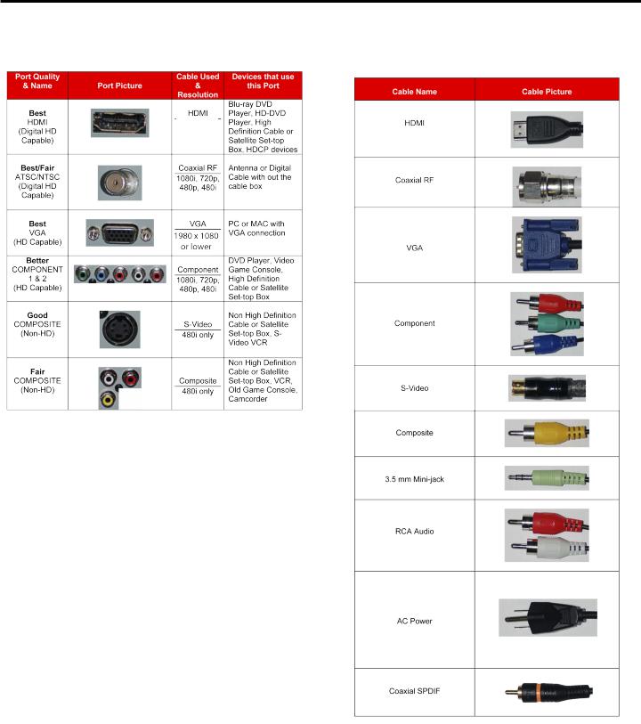
Cable Descriptions: |
1080p, 1080i 720p, 480p 480i
Red
Green
Blue
Yellow
Green
Red
White
Page 10
TV Installation – Rear Panel Connections
Switching Sources for Ports:
Your SunBrite TV offers several options when connecting your devices to the TV. The chart below will help you understand which source you switch to for each of the ports.
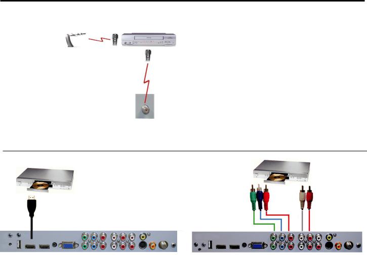
CONNECTING TO AN ANTENNA
Connecting to Digital Cable without Cable Box or Antenna
1.Make sure the power to the TV is turned off.
2.Connect the Coaxial RF cable from your antenna or digital cable to the ATSC/NTSC port off the back of the TV.
3.Turn on the TV.
4.Select TV (Air) for antenna or TV (Cable) for digital cable from either your remote control’s source button or source button on the right side of the TV.
5.Use the On-Screen Display to scan for channels.
Please Note :
Connecting to Cable or Antenna
1.Make sure the power of the TV is turned off.
2.Connect the Coaxial RF cable from your antenna or cable to the
ATSC/NTSC port off the back of the TV.
3.Turn on the TV.
4.Select TV (Air) for antenna or TV (Cable) for cable from either your remote control’s source button or source button on the right side of the TV.
5.Use the On Screen Display to scan for channels.
1.Not all broadcasts are in High Definition (HD). Please refer to your local broadcasting stations for more information.
2.The TV’s tuner is designed for HDTV therefore requires a stronger signal than normal TVs. If you cannot achieve that signal level with your antenna or cable, the TV might lose picture or sound.
SunBriteTV Model 5570HD and 6570HD Operator’s Manual |
Page 11 |
TV Installation – Rear Panel Connection Diagrams
CONNECTING TO AN ANTENNA--(Continued)
Connecting to Cable or Antenna through VCR
1.Make sure the power of the TV is turned off.
2.Make sure there is an antenna or cable connection to the VCR already.
3.Use a Coaxial RF cable and connect from your VCR’s Antenna Out or Output to TV to the ATSC/ NTSC port of your TV.
4.Turn on the TV.
5.Select TV (Air) for antenna or TV (Cable) for digital cable from either your remote control’s source button or source button on the TV.
6.Use the On-Screen Display to scan for channels.
Please Note :
1.Some VCRs must be turned On before its output will have a signal to the TV. Please consult your VCR manual for further reference.
2.Not all broadcasts are in High Definition (HD). Please refer to your local broadcasting stations for more information.
3.This model’s tuner is designed for HDTV therefore it requires a stronger signal than normal TVs. If you cannot achieve that signal level with your antenna or cable, the TV might lose picture or sound.
4.This TV will turn off automatically if there’s no signal present for more than 15 minutes.
CONNECTING TO A DVD PLAYER |
|
|
Connecting with |
|
Component |
Connecting with HDMI (Best) |
(Better) |
1.Make sure the power of the TV and your DVD player is turned off.
2.Connect a HDMI cable to the HDMI port of your DVD player and the other end to the HDMI port off the back of your TV.
3.Turn on the TV and your DVD player.
4.Use the remote control’s source button or the source button on the TV to switch to HDMI.
Please Note :
1.Refer to the DVD player’s manual to make sure the DVD player is configured to output correctly to the TV.
2.This TV does not decode Bit stream digital audio, so make sure the DVD is setup for PCM digital audio through HDMI.
3.If HDMI 1 is occupied, use HDMI 2 as your connection port.
1.Make sure the power of TV and your DVD player is turned off.
2.With a Component Cable, connect the green connector to the DVD player and Component 1’s green connector port on the TV.
3.Connect the blue color connector to your DVD player and Component 1’s blue connector port on the TV.
4.Connect the red color connector to both your DVD player and Component 1’s red connector port on the TV.
5.With an RCA Audio Cable, connect the white color connector to both your DVD player and Component 1’s white connector port on the TV.
6.Connect the red color connector to both your DVD player and
7.Component 1’s red connector port on the TV.
8.Turn on the TV and your DVD player. Use the remote control’s source button or the source button on the TV to switch to YPbPr1.
Please Note :
1.If Component 1 is already occupied, please use Component 2 as your connection port and switch to source YPbPr2.
2.Refer to the DVD player’s manual to make sure the DVD player is configured to output correctly to the TV.
3.This TV will turn off automatically if there’s no signal present for more than 15 minutes.
Page 12
TV Installation – Rear Panel Connection Diagrams
CONNECTING TO A DVD PLAYER (Continued)
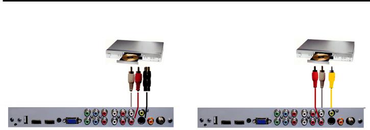
Connecting with S-Video (fair) |
Connecting with |
|
Composite (Fair) |
1.Make sure the power of the TV and your DVD player is turned off.
2.Obtain an S-Video Cable. Connect the S-Video connector to both your DVD player and Composite’s S-Video connector port off the back of your TV.
3.Obtain a RCA Audio Cable. Connect the white color connector to both your DVD player and Composite’s white connector port off the back of your TV.
4.Connect the red color connector to both your DVD player and Composite’s red connector port off the back of your TV.
5.Turn on the TV and your DVD player.
6.Use the remote control’s source button or the source button on the right side of the TV to switch to AV1 (S-Video).
Please note:
1.Make sure the power of the TV and your DVD player is turned off.
2.Obtain a Yellow Video Cable. Connect the Yellow Video connector to both your DVD player and Composite’s Yellow Video connector port off the back of your TV.
3.Obtain a RCA Audio Cable. Connect the white color connector to both your DVD player and Composite’s white connector port off the back of your TV.
4.Connect the red color connector to both your DVD player and Composite’s red connector port off the back of your TV.
5.Turn on the TV and your DVD player.
6.Use the remote control’s source button or the source button on the right side of the TV to switch to AV1 (CVBS).
1.If AV 1 is already occupied, use AV2, as your connection port, and switch source to AV 2 (S-Video)
2.Reference the DVD player’s manual to make sure the DVD player is configured to output correctly to the TV.
3.This TV will turn off automatically if there’s no signal present for more than 15 minutes.
SunBriteTV Model 5570HD and 6570HD Operator’s Manual |
Page 13 |
 Loading...