

Page 1
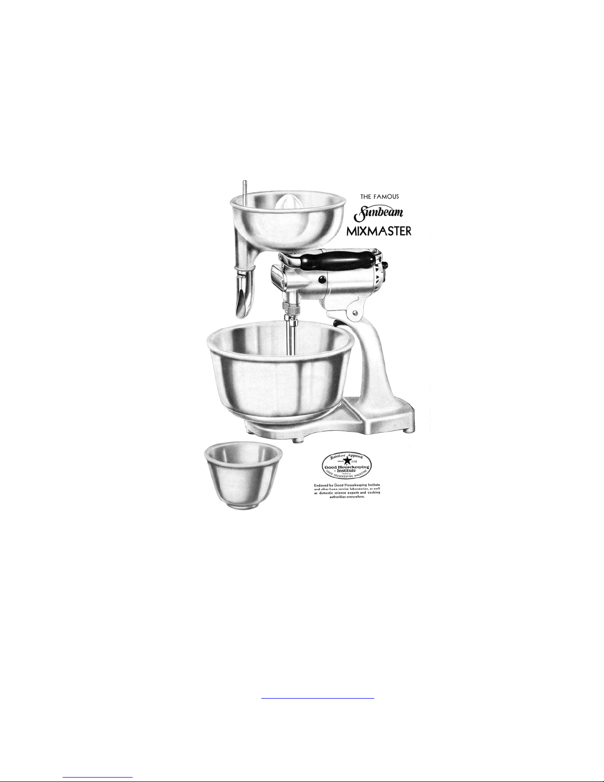
Instructions for Servicing Vintage
Sunbeam Mixmasters
Original Sunbeam Factory Service Information for Models:
Compiled by
New Albany, PA
1, 3A, 3B, 3 ‘Automatic’
Dave’s Repair Service
2004 All Rights Reserved
www.DavesRepair.com
Page 2

SERVICE BULLETIN NO. 14 - Revised April 27, 1949
Sunbeam Corporation
5600 Roosevelt Rd., Chicago
INSTRUCTIONS FOR SERVICING SUNBEAM MIXMASTERS
MODEL 1 (ONE) AUTOMATIC
MODELS 3A and 3B AUTOMATIC
(See Model Number Stamped on Motor Name Plate or on Mixmaster Base)
GENERAL
Before giving detailed instructions for servicing Models 1, 3A and
3B, a few general remarks should be helpful. Models 3A and 3B are
alike except for color and are very similar to Model 1 except for
external design and alight changes in electric circuit (compare
wiring diagram on Page 2 with blue print over Page 3). The servicing
instructions starting on Page 3, although referring directly to Model
1, actually apply to all three models.
The AUTOMATIC Mixmasters have greater power, and the speed control
differs from that in earlier models, and in other mixers. Older
Mixmaster models had a rheostat connected in series with the motor,
to limit the voltage applied to the motor; which, in turn, limited
the speed when a slower whipper speed was required. With this method
there was a loss of power on the lower speeds.
The automatic Mixmasters have a governor control. The governor
consists of contact breaking points placed in series with the motor,
which open at a predetermined speed, and close again at a speed only
slightly lower. Thus a constant speed is maintained, even with
variations in the load or line voltage, and full power is available
at all speeds. The breaker points are mounted on a lever arm and so
arranged on a disc, which revolves with the armature, that
centrifugal force opens the breaker points as the speed goes above a
certain value. This value is varied when the switch knob is turned,
changing the distance between the governor slide and the governor
breaker point arm, and determining the speed at which the contact
points will open.
To give the breaker points a long life, a condenser and a resistor
are shunted across them. The resistor not only lengthens the life of
the points but also smoothes out the motor speed by allowing a small
fraction of the current to flow through the motor when the breaker
points- are open.
A second condenser is included in Automatic Mixmasters to eliminate
radio interference radiated by the brushes and breaker points. Both
condensers on Model 1 are housed in the same metal container. To
distinguish between the lead wires running from each of the two
condensers note that the breaker point condenser has metallic
shielding on the lead wires, but the other condenser has no such
shielding on the leads. On Models 3.A and 3B these two condensers are
separate. See Key numbers 69 and 140 on parts list diagram.
There are two sets of breaker points on the governor disc but only
one set is connected in the electric circuit and these are Tungsten
points. The other
Page 3
or “dummy” set is made of cold rolled steel. The purpose of the steel point and
lever arm is to balance the movement of the tungsten point and its lever arm
and to give smooth, quiet operation, which is important. Since the breaker
points are mounted on a rotating disc to enable centrifugal force to act upon
them, the current is fed to the rotating governor through a pair of stationary
brushes, hence there are two governor brushes.
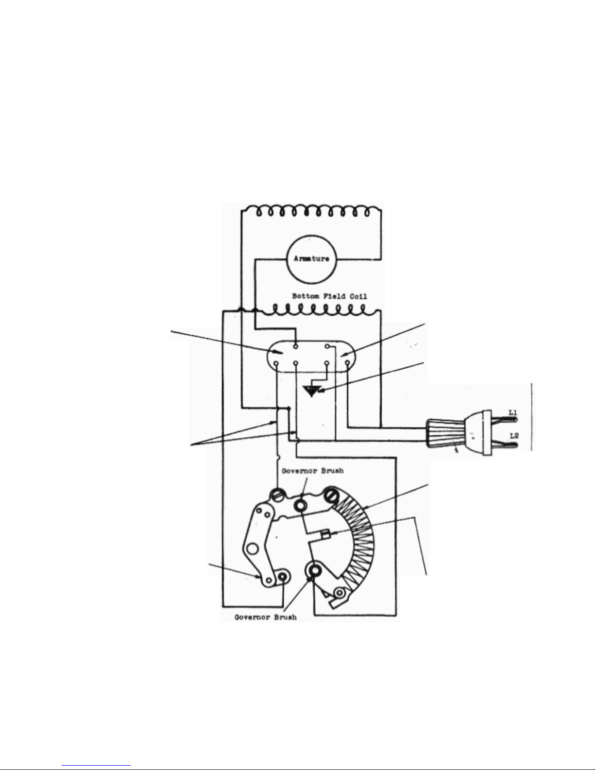
The wiring diagram below will help clarify the servicing and repair of this
model.
Governor
Condenser
Circuit
Shielded
Leads
Top Field Coil
Filter Condenser
Circuit
Mixer Case
Line Switch
Resistor
Governor Breaker Points
Wiring Diagram for MIXMASTER
Model 1 AUTOMATIC
Page 4

HOW TO SERVICE MODEL 1 AUTOMATIC MIXMASTER
1. If Mixmaster does not run when electric cord is plugged into an outlet of
the same voltage shown on the motor name plate, detach the cord from the
socket and remove switch cover (see Key #71 on the general diagram at the
end of this bulletin) by taking out the two screws (90 and 65); then plug
the cord into the socket again and with a piece of wood press down on
phosphor bronze switch (105), taking care to keep the wood clear from
rotating governor
disc (100). If mixer should start that is an indication
that switch rod and bakelite insulator (115) is short and should be removed
from switch cover and a new one installed.
If, on the other hand, the motor should not start when pressing down switch
part (105) remove the governor disc assembly (100) and install a new
governor disc as outlined in sections 5—A and 13—B. Then close the switch
again as mentioned above. If motor still does not start proceed as follows:
1—A. Reassemble original parts (see sections 14.A and 15) and check for
continuity of circuit with a test lamp. Place tips of tester wires on each
prong of the appliance plug at the end of the cord. If the lamp (50W) lights
to nearly normal brightness with the mixer control knob in any position
other than “OFF” it indicates that the electric circuit is complete and the
motor should run, otherwise the bearings may be tight--see section 3. If the
lamp does not light the circuit is open, and a complete test should be made
of the electric cord as in section 2. If light is illuminated to
approximately half normal brightness, that indicates that the motor circuit
proper is open and current is flowing through resistor (43) only--proceed to
take motor down as in sections 5, 5—A, 5—B and 6 and test armature (27) and
field coils (44), for open circuit, also inspect brushes (19) and brush
springs (18).
2. Testing and Replacing the E1ectric Cord (33)
Take out screw (87), remove cover (84) arid rubber insulation (95) and pull
out connections from terminal insulation box. Place test tip on one of these
connections and the other tip on first one prong of the appliance plug and
then the other. One of these wires should light; if it does then move test
tips over to the other connection in terminal box and to the other prong of
the plug. A light should be obtained there also if the cord is in good
order. If either one of these wires do not light thru, cord should be
replaced.
2—A. Next, use a hot soldering iron and pliers, untwist the terminal leads and
detach cord. Attach a new cord and plug and twist and solder leads. No
taping of the leads need be done but fold leads carefully into terminal
insulation box (96) so they do not touch the case. Replace rubber insulation
(95) cover (84) and screw (87) and test mixer for ground by touching first
one terminal prong of plug on cord with one tip of test lamp, and the other
test tip on the motor case. Then move over to the other prong of the plug.
The lamp should not light. If it does go back and check wiring.
Page 5

3. Frozen Bearings
To check the bearings to find if any have seized because of lack of oil or
other causes, grasp the lower part of the whippers (21), and turn
inward
the bearings for whipper spindle sleeves (13 and 20), motor bearings (45), or
governor slide bearing (113) have seized it will be impossible to turn the
whippers. To locate seized bearing and repair see sections 4, 5, 5-A, 5-B, 6,
7 and 9. If all bearings are free the whippers will turn freely. The whippers
should not turn at all in an
outward
direction; if they do, that indicates a
worm gear (9) is stripped and the gear should be taken out and replaced as in
sections 4 and 16.
4. Removal of Whipper Spindle Sleeve and Oil Retainer Assemblies (13 and 20
To remove whipper spindle sleeves unscrew the two gear case cover screws (8)
and take off gear case cover (7). Put both whippers (21) in place and rotate
inward until worm gear set screws (10) can be seen, then loosen set screws
with “T” handled worm gear set screw wrench. Next, grasp the sleeves and pull
them down and out of the gear case (5). If juicer sleeve (20) is frozen in the
bearing it may be necessary to drive it out, using a brass rod which will pass
thru the bearing and which can be driven downward from the hole in top of gear
case. Another helpful method of removing frozen spindle sleeves is to turn the
motor up-side-down and squirt kerosene from a can between the outside of the
sleeve, and the bearing part of the gear case; then remove switch cover
assembly (71) as in section 5. Grasp the governor disc (100) in one hand and
insert a whipper in the frozen spindle sleeve and try to turn both in the same
motor
direction with a back—and—forth movement. The frozen spindle should
gradually loosen until it can be rotated and set screw (10) is brought to the
front of the gear case. If whipper spindle sleeves are frozen it is necessary
to replace the sleeves only, see sections 16 and 17. But if the whipper
spindle sleeves come out easily and the
armature
cannot be turned by grasping
the worm shaft, the motor bearings (45) are probably seized or are badly
gummed up. To continue it will be necessary to disassemble motor as in
following sections.
5. How to Remove Governor (100) and
Switch Mounting Bracket (105)
.
Remove screw 90 and 65 and gently tap switch cover 71 until the lacquer is
broken and cover can be pulled straight back and off. A final test for frozen
or gummy motor bearings (45) may be made at this point by grasping the
governor disc (100) and turning it, which normally should turn freely (with
the armature shaft) if bearings are in good order. If governor and armature do
turn, it is probable that the governor slide bearing in the switch cover is
frozen or gummy and should be examined, washed out with kerosene and re-oiled,
or replaced with a new governor slide, bearing and lever assembly (113).
5-A. To continue the removal of governor (100) insert the Allen Head governor
wrench into governor set screw (101) and loosen set screw, two or three turns,
to the left. Governor may then be pulled off the armature shaft.
. If
)
Page 6

5-B. Next disconnect the three leads fastened under screws and nuts 106, 92, and
94 and take out two screws (91) which hold switch mounting bracket assembly
(105) in motor. Remove this assembly, including the two governor brushes (97)
and resistor (43).
6. Removing
the Armature (27)
Following the work outlined in the preceding sections take out the two
retaining screws (23) and gently tap front housing to help break the lacquer
finish at the point where the front part of the motor case joins the rear part
(28). When the two pieces have been separated the armature may be removed and
a tight bearing located.
7. To Free Tight Motor Bearings (45
)
First, thoroughly clean bearing holes by wiping with a clean rag, F1ush out
oil holes and bearings (45) with kerosene fed from the spout of an oil can.
Wipe thoroughly until dry. Rub armature shaft with an oilstone to remove
scoring or roughness, apply oil to the shaft and see that it is free to turn
in either bearing. (NOTE: If bearings are worn, or require replacement for
any reason, return motor to factory for service. Bearings in Model 1 are oil
less-type and must not be reamed.) It is well at this point, since the
armature is out, to test it, and the field coils, for grounds, etc. as
follows.
8. Testing Armature (27) and Field Coils (44)
To check the armature for grounds touch one wire tip of test lamp on the
armature shaft, then touch the other on any commutator bar or bars. If test
lamp lights a ground or conducting path is present between live parts and
laminations, a condition that should not exist, and the armature should be
replaced with a new one. Examine commutator bars to see if there are burned
marks along the edges of any of the bars. Such marks indicate short circuited
winding and armature should be replaced. Also observe if any wires leading
from winding to the commutator are broken or damaged from rubbing on the brush
leads. Replace armature if this condition is found.
Commutator should be smooth without excessive ridges or rings cut in it.
Commutators with excessive rings cut in them by the motor brushes (19)
should be replaced, or if a lathe is available they may be turned down with
a smooth cut.
Check field coils through leads and motor case, for grounds, and through both
leads for open circuit.
9. Assembling Motor
The armature shaft should be inserted into the back bearing, and the front
housing then slipped part way onto the front of the armature shaft. The brush
lead wires with the clips should be clipped onto the brush holders (18). The
lead and clip coming direct from the
holder on the
on the
left
right, and the lead and clip from the condenser on brush holder
, as the workman looks at the back of the motor, After the brush
field
coil (44) should put on the brush
clips are put on the brush holders and the lead wires are carefully arranged
not to rub against the armature, and when the condenser (69) has been started
into the space provided for it in the
Page 7

bottom of gear case (5), the two parts of the motor housing should be brought
together with care to prevent dirt, etc. from getting between the joint. The
two retaining screws (23) should be in place and then tightened up evenly so
there will be no misalignment of bearings. This is very important. Be sure
that the armature spins FREELY in the bearings at this point.
9—A. Note also how the front part of the motor housing fits into the back part.
The position of the two parts when together is held approximately by a
tongue, which is slipped into a slot, but this allows for some “play”. After
the retaining screws (23) are tightened see that the special gear Box Gauge,
or a Power Unit attachment, when inserted into whipper spindle sleeve (20)
also slips into the two holes in the base freely. If locating buttons on the
bottom of the gear box gauge (or power unit) are to one side of the holes in
the base, loosen retaining screws (23) and swing gear case (5) until
alignment is attained, then tighten screws (23) again,
evenly
.
10. Commutator Brushes (19)
Insert brushes into brush holders (18) so that curved end of the brush
conforms to the curved surface of the commutator (this is very important
because it, minimizes sparking at the commutator). The brushes should be
free
from oil and grease and if worn short should be replaced with new. The
brush spring (17) should have as good a tension as when new. If tension is
low the spring should be replaced.
Insert brush springs and tighten brush screw (16) securely so screw will not
loosen while motor is running,
11. Fitting the Switch Mounting Bracket Assembly (105) in the Motor
Put the Switch Mounting Bracket and resistor (43) in place and screw down the
two mounting bracket screws (91). Facing the back end of the motor, the field
coil (44) lead should be connected to point 106. The
shielded
lead should then be connected to point. 92 by first passing it under
longest
condenser (69)
the switch lever, being sure that it does not rub or make contact in any
place except under screw 92. Next fasten the other condenser shielded lead
under nut 94, also taking care that it does not make contact with the case,
which would cause a ground.
12. Governor Brush and Spring Assembly (97)
To fit the two governor brushes and springs in their holders, in the switch
mounting bracket assembly (105), first see that the holders are free from
carbon dust or any gummy substance resulting from carbon dust mixing with
oil. The governor brushes should be approximately 11/32” long and perfectly
round without worn spots forming shoulders on the sides as this interferes
with the travel of the brush The springs should be in good condition to hold
tension on the brush, and free from wear caused by rubbing on the sides of
the brush holder. The
copper
pigtail connection should be fastened to the
bottom coil of the spring at the brush so the spring will not have to carry
the current to feed the brush. The straight portion on the other end of the
spring locates in a hole at the bottom of the brush holder to prevent turning
of the brush and excessive side wear on the brush. The
Page 8

brush should be pushed down into the brush holder a few times to be certain
that it will travel or slide freely in and out of the bolder. If governor
brushes and springs are not in first class condition as outlined above they
should be replaced.
13. Fitting the Governor (100) on the Armature Shaft
The governor assembly should be thoroughly examined before placing on the
armature shaft. First inspect the brass collector rings on the back of the
disc. If these are badly pitted or burned the governor (100) should be
replaced unless it is possible to face off the rings in a lathe. Care must
be taken, if this is done, to obtain a smooth cut and above all to see that
the governor disc runs true on the arbor before and after facing. This is
very important as a noisy motor, excessive governor brush wear, and worn
bearings will result if disc does not run true, or if it is thrown out of
balance. There is a limit to the amount of the cut or to the number of cuts
that can be taken off the rings, because if the heads of the rivets which
hold the rings to the Bakelite disc are cut away the rings will be thrown
off at high speed.
13-A. Next examine the tungsten contact breaker point (102) mounted on the end of
the lever arm. If badly pitted or burned the governor assembly (100) should
be replaced. No filing, bending or changes should be made on the tungsten
points, or on the lever arm. It will be noticed that there are two lever
arms (102 and 103) on the disc but as explained in the introduction to this
bulletin close observation will show that only one arm is fitted with
tungsten points. The other points are larger and are made of cold rolled
steel. These C.B.S. points carry no current but are for the purpose only of
balancing the governor at all speeds.
13-B. After examination has showed the governor (100) to be in good condition or
that a new one is necessary place governor on the armature shaft. First
observe the depression on the armature shaft and place the governor on the
shaft so that governor set screw (101) can be screwed into the depression,
or hole, in the armature shaft. The governor brushes (97) must be forced
back into the brush holders carefully as the governor is pushed onto the
shaft so brushes will not be damaged or broken. Be certain that the set
screw (101) is turned with the Allen Head Wrench until it is tight and that
no wires are rubbing, as the governor is revolved by hand. The governor and
armature should revolve FREELY.
The operation of the motor may now be checked by plugging the cord into a
socket and carefully closing switch (105) with a pencil or round stick in
much manner that it will not be struck by the governor (100) when it
rotates. Motor should operate on “high” speed only.
14. Fitting Switch Knob (70) and Switch cover (71) Assembly
Examine parts to see that the governor slide assembly (113) travels in and
out as the switch knob is turned, when held in the normal position. The
switch rod (115) should be thrust forward as the switch knob leaves the
“OFF” position on the outside of the cover, and should stay out for the
remainder of the travel of the governor slide.
Page 9

The felt wick (110) in the cover should feed oil to the governor slide
bearing.
14-A.If the parts referred to in the preceding section are all in good shape the
switch cover (71) may be put in place. First turn the Switch Knob
(70) to the “OFF” position, then governor slide (113) should be started on
the armature shaft in such manner that the forked shaped legs will
enter the slot provided in the governor disc (100) around the hub. The cover
should then slip into place and the two screws (90 and 65) can be inserted
and screwed in. The rear handle bracket (77) should be placed under screw
90. WARNING: Do not start mixer
adjusting
armature thrust screw, if thrust screw (26) and switch knob (70)
when
back cover is on without first
have been disassembled (see section 15).
15. Armature Thrust Screw Assembly (26
)
The armature thrust screw assembly consists of a piece of oil-less type
bearing material pressed into a hole in the end of a steel screw. The thrust
screw assembly (26) should be turned to the right with a screwdriver until
the bearing end presses against the end of the armature shaft, then the
thrust screw should be backed off (turned to the left) 1/8 of a turn. While
the thrust screw is held in this position with the screwdriver, the thrust
screw lock nut (25) should be tightened securely with the socket wrench
supplied for adjusting thrust screw lock nut. Thrust screw nut washer (88)
and switch knob (70) are also held in p1ace by thrust screw lock nut 25.
The motor bearings (45) may be checked at this point by plugging the cord
into a socket and turning the switch knob (70). All speeds should be
obtainable.
16. Fitting the Worm Gears (9) in the Gear Case (5)
Before installing worm gears, inspect the whipper spindle sleeve bearing
surfaces and if scored or rough, smooth the bearing, or if necessary replace
gear case (5). Next inspect the whipper spindle sleeves (13 and 20) and
remove scores or roughness with fine emery cloth or file. If scored too much
the sleeves should be replaced with new.
To start assembling the parts, hold gear (9) by the metal hub with the
special thin pliers and insert gear into right hand side of the gear
compartment, with the hub down. Also, hold gear so the setscrew hole in the
hub is to the front, facing the workman. This is important, because it
determines the timing of the whippers (21). Next, while holding gear (9) in
position as described above (use left hand for this purpose), take the
juicer spindle sleeve (20) in right hand, and push it up thru the gear case
(5) into the gear (9). While doing this, have the depression for worm gear
set screw (10), which is drilled on the sleeve, in line with, and visible
thru the set screw hole in the hub of the gear (9). Insert set screw (10)
using special “T” handled socket wrench and turn down set screw’ TIGHTLY.
Page 10

Follow the same procedure with the other worm gear (9) and assemble it to
whipper spindle sleeve 13. Again be sure that the gears (9) are fitted to
sleeves with set screw holes held exactly in front, in order to get proper
timing of the whippers. It is well to put film of oil on the whipper spindle
sleeves (13 and 20) before inserting them into the gear case (5) bearings.
17. Greasing the Worm gears
Put about TWO TABLESPOONS ONLY of special Mixmaster lubricant (86) into the
gear compartment, placing it in the metal worm and gear (9) teeth as much as
possible. It is essential to use special Mixmaster lubricant. This grease
was chosen after many tests because it adheres properly to the surfaces to
be lubricated, and does not thin out when warm.
Fit gear case cover (7) and use new gasket (6) if necessary. Fasten cover
with two screws (8) and tighten. Place a few drops of oil in all oil holes
and run motor idle for a time to free the gears.
18. Adjusting the position of the Motor and Whippers (2l
)
The adjustment screw (32) is provided in the top of the upright (46) so the
position of the whippers may be set permanently for the bowls, and to allow
a free engagement of the Power Unit Attachment and other attachments,
between the two holes in the base of the Mixmaster’ and the motor.
To properly adjust screw 32, put the motor on the standard, take the Special
Gear box gauge, or a Power Unit Attachment, and slip it into the whipper
spindle sleeve (20). Lower the motor head to its horizontal position and
note whether the two buttons on the bottom of the foot of the gear box
gauge, or Power Unit, are forward of the two holes in the base, or back of
them. If ahead of the holes, loosen lock nut (31) and turn screw (32)
down
until buttons enter holes freely. Also check the space between the bottoms
of the whippers (21), and the surface of the mixing bowl (48, 49 and 62).
Whippers must come
will be mixed
and
close
to surface of bowl so all ingredients in the bowl
so bowl will turn) but the whippers should not rub on
bowl. If whippers rub set adjusting screw 32 higher. If whippers do not come
very close to surface of bowl, adjust screw 32
lower
. When the screw has
been properly adjusted lock it in place by tightening nut 31.
19. Replacement of Condensers (69
)
19—A. Should either the condenser for governor breaker points, or the filter
condenser (see the general remarks on page one of this bulletin) fail, the
removal of both condensers is necessary since they are housed in the same
metal container. Proceed as follows:
First, remove switch cover assembly (71) and governor (100) as in
section 5 and 5—A, an4 take out switch mounting bracket (105) as in
section 5—B.
Second, take out retaining screws (23) as in section 6 and separate
motor housing.
Page 11

Third, remove screw (87) terminal box cover (84) and terminal
insulation cover (95). Untwist the lead wires with a hot soldering iron
and pliers, and remove the terminal insulation box (96) by lifting
straight up. The condenser (69) is now ready to be taken out but
workman should carefully note the layout of the leads before removing.
Six leads come out of the condenser unit. The two with the metal
shielding and a third in the same group, which has a brush clip on it,
are terminals for the governor breaker point condenser, and should be
on the left side. The other three leads, on the right side, are for the
filter condenser. The two filter condenser leads
without
1ugs are
connected across the line cord in the terminal insulation box (96) and
the third filter condenser lead
with
lug is connected to the motor
housing under screw 66.
19—B. To fit a new condenser unit start the two long shielded leads in between the
motor housing and field coil (44); then the three filter condenser leads
should be led down into terminal box space in motor case, and the condenser
unit pushed all the way up in the gear case housing (5). Do not cross
shielded leads over each other, or cross the filter condenser leads because
they are in the correct relation to each other. Connect the ground lead from
the filter condenser (the lead with the lug) under screw (66). Next replace
the terminal insulation box (96) and bring the field leads and condenser
leads up thru the holes provided. The leads may now be connected. Twist one
field lead, one filter condenser lead and one cord lead together and solder.
Then repeat the same with the other 3 leads, twisting and soldering. Fold
soldered leads into terminal insulation box (96) carefully to avoid grounds
and replace terminal insulation (95), terminal box cover (84) and screw
(87). Reassemble motor as in sections 9 to 14-A.
20. Radio Interference
Model 1 Automatic Mixmaster is equipped with a filter condenser similar to
that used in previous models. This part practically never requires
attention, but if there should be extreme radio interference, it may mean
the filter condenser needs to be replaced--proceed as in sections 19, l9-A,
and 19-B. Should the user of the Mixmaster prefer not to have the non—radio
interfering feature it may be removed by disconnecting the filter condenser
ground lead from the motor housing under screw (66) and taping the end of
the wire.
Synopsis of Repairs and How to Make Them
21. Motor crawls but has no “High” Speed
21-A. Contact breaker points (102) may be burned and do not make
contact; motor runs on current received thru resistor (43) only. Replace
governor (100) as in sections 5, 5-A, 13, 13-A, 13-B, 14, and 14-A.
21-B The Governor brushes (97) may be worn away. Repair as in sections
5, 5-A, 12, 13, 13-A, 13-B, and 14-A.
Page 12

22. Motor Runs on High Speed Only
22-A. Breaker point condenser (connected across terminals 92 and 94) is
shorted. Replace condenser unit (69) as in section 19.
22-B. Tungsten points (102) may be fused together. Replace governor (100)
as in sections 5, 5-A, 13, 13-A, 13-B 14, and 14-A.
23. Motor Jerks When Running, Especially on Low Speed
23-A. Breaker point condenser (connected across points 92 and
94) is open. This is also accompanied by excessive sparking
at the governor breaker points (102). Replace condenser unit
(69) as in section 19.
23—B. Open circuit in resistor (43). Replace resistor by taking down
back end of motor as in sections 5, 5-A, 5-13. Change resistor and
reassemble as in sections 11, 12, 13, 13-B, 14, 14-A.
24. Motor Runs Normally, Except 1st Speed is Too Low
(Less than 275 R.P.M. at whipper spindle sleeve (20).
24—A. Governor (100) needs replacement as in sections 5, 5-A, 13, 13-B,
14, 14—A.
25. Motor Does Not Run At All
.
25—A. Switch Rod (115) is short, or switch (105) is open. Repair as in
section 1, 5, 5-A, 5-B and examine silver contacts on 105, Possibly
switch lever (105) should be bent down on the contact end and up in the
center so as to touch end of switch rod. Reassemble as in sections 11,
12, 13, 13-A, 13-B, and 14-A.
25-B. Commutator
brushes (19) need replacement. See section l0.
25-C. Governor
brushes (97) need replacement. Repair as in sections 5,
5-A, 12, 13, 13-A, 13-B, and 14-A.
25—D. Motor
Bearings (45) frozen. See section 3.
25—E. Whipper Spindle Sleeves frozen in gear case bearings.
See section 3.
25—F. Cord broken. Test and repair cord as in sections l—A, 2, and 2-A.
26. Excessive Radio Interference
26-A. Condenser may have open circuit. See section 20.
Page 13

27. Excessive Shock from Motor Case
27-A. Ground, or short circuit, thru insulation. Take down motor
and test as in sections 5, 5-A, 5-B, 6, 8.
27-B. If filter condenser is grounded to its own metal container,
replace condenser. See section 20.
28. Motor Loss of Power
(temperature rise excessive)
28-A. Partially
frozen bearings. See section 3.
28-B, Armature requires replacement. Possibly commutator brushes are
sparking badly. Repair as in sections 5 to 14-A inclusive.
28—C. Field coils partially shorted or “slow”. Return motor to factory
for service.
29. Motor Runs but Whippers Do Not
.
29—A. Worm gear (9) stripped or loose from metal hub. Repair as in
sections 4, 16 and 17.
* * * * * * * * * *
THE TOOLS REQUIRED FOR USE WITH BULLETIN ARE:
One Tool T—20213 Socket Wrench for adjusting Thrust Screw Lock Nut (75N)
One T~o1 T—16023 “T” Handled wrench for worm gear set screw (P9922)
Standard Allen Head Wrench, size 5/64”. Purchase locally.
Standard Long Nose pliers. Purchase locally.
Single Open-end wrench for adjusting screw lock nut (P6649). Purchase locally.
Open End Wrench for adjusting screw (P—20751). Purchase locally.
Special Gear Box Gauge (Not Available). Adjust Height 6—3/8” from base.
SUNBEAM CORPORATION
5600 West Roosevelt Road
Chicago 50, IL. — U. S. A.
Page 14

SERVICE BULLETIN NO. 18
INSTRUCTIONS FOR SERVICING SUNBEAM MIXMASTER
MODEL 3 AUTOMATIC
(See Model Number Stamped on Bottom of Mixmaster Base)
Revised May 14, 1949
The Model 3 Automatic Mixmaster motor is controlled by an air governor that
operates on the following principle: A fan draws air into the motor housing
through the grille on the front, carries it past the armature and field coils, on
through the governor control, and delivers it out the back of the motor. Between
the fan and the air vent is a Bakelite disc that closes the back or the motor
housing. In the center or the disc a rectangular opening is placed, then across
the opening a thin blue steel shutter plate, or diaphragm is fitted with one edge
fixed to the Bakelite disc. A contact breaker point is riveted on the diaphragm.
Directly opposite another breaker point is attached to an arm.
As the air is pulled through the motor it pushes back the diaphragm to provide an
opening for the air to flow through and this action breaks the current flow
through the governor contact points. The amount or air pressure required to open
the diaphragm depends upon the resistance of the diaphragm to the air. To control
this resistance, tension is applied through the contact breaker point fitted on
an arm (this breaker point will be celled the Fixed
Contact throughout the
remainder of this bulletin, because the position of that contact point remains
fixed for any particular speed, its position being determined by the setting of
the switch knob).
When you turn the switch knob at the back of the motor you increase or decrease
the tension on the diaphragm by moving the arm slightly backward or forward. With
the switch knob turned to the lower speeds the tension against the diaphragm is
very light; the diaphragm opens easily, thereby breaking the current quickly. But
when the knob is turned to the higher speeds the arm applies more tension on the
diaphragm and a greater air pressure is required to open it and break the
current. Thus by adjusting the tension on the diaphragm and by alternately making
and breaking the current flow at a very rapid rate the governor maintains a
constant motor speed under all load and nominal voltage variations.
A condenser and resistor fitted on the Bakelite governor disc are shunted across
the governor breaker points to give the points long life and to reduce radio
interference. The resistor also smoothes out the operation of the motor by
allowing a small fraction of the current to flow through the motor while the
breaker points are open momentarily. A second filter condenser is fitted in the
lower part of the motor housing to reduce and eliminate radio interference.
Wiring Diagram Model 3 Automatic Mixmaster
Page 15

HOW TO SERVICE MODEL 3 AUTOMATIC MIXMASTER
A. Taking the Motor Apart
The parts referred to in this bulletin are illustrated on the diagram attached
to the end of the bulletin with parts list. The tools that will be mentioned
are described on page 9. Threads on all screws and other fasteners used in the
Model 3 Automatic are right hand, except armature thrust adjustment cap (see
Key number 107 on parts diagram), which is left hand.
A-1. To take off switch knob (key number 70) in rear of motor, remove switch knob
screw (119.). Pull out knob, also take out round fiber switch pin (325) and.
square speed adjustment cam pin nut (136) and cam pin (137).
A-2. To remove rear motor cover (128), turn out the two round head rear cover
screws (65) at the bottom (short screw) and top (long screw) of cover. When
removing cover it may be necessary to tap it a little to break the seal caused
by the paint sticking where the cover joins the motor housing.
A-3. To take out Bakelite governor assembly (100), first remove the three nickeled
mounting plate screws (91) and two of the binder head screws (122), which
fasten one lead wire to the switch lever (105) and one to the governor
diaphragm (138). Pull out Bakelite governor assembly while guiding the two
lead wires carefully through the slots at the outer edge of the Bakelite disc.
Care should also be taken not to break or lose the thin rubber gasket (116)
fitted around the circumference of the Bakelite disc.
A-4. To remove the fan housing and rear bearing bushing assembly (key number 135)
unscrew the three hexagonal fan housing retaining studs (130) –1/4 in. wrench
is used for this purpose - and pull out fan housing, using pliers if
necessary. Be careful of the two wire leads.
A-5. Now remove both armature carbon brushes (19) by unscrewing black Bakelite cap
brush screws (16) on outside of motor housing. Exercise care in not letting
brush springs (17) or brushes jump out end get lost.
A-6. To loosen the baffle plate (132) turn out the two flat head baffle plate-
retaining screws (23) and remove rear cover locating key (131).
A-7. Armature assembly (27) may now be removed, together with the fan (133) and
baffle plate (132), without disassembling the parts in the front of the motor,
by just pulling out the armature assembly. NOTE: If it is planned to fit this
assembly back in the motor without adjusting the parts in the front of the
motor, care should be taken to prevent any change in the original relative
position of the two whipper spindle s1eeves (13 and 20), otherwise the spindle
sleeves will get out of alignment and the blades on the whippers will strike
each other when turning. See Section B2A for proper method of fitting armature
assembly into the motor without removing parts at the front.
A-8. The fan (133) can be taken off the armature by removing fan retaining nut
(134). 7/16 in. wrench may be used for this purpose. Turn nut to the left.
Page 16

4
A-9. Brush holders (18) occasionally become loose because of shrinkage due to heat
from the motor under prolonged use. To tighten or replace brush holders, set
screws (22) which keep the holders in place can be adjusted. With a long thin
screw driver inserted in the same screw hole through which baffle p1ate
retaining screws (23) enter.
A-l0. To remove front motor cover (7) and Bakelite motor handle (78), first push
Bakelite handle down into position along the side of the motor, then unscrew
grille and front motor cover retaining screw (114). Pull out the front cover.
The Bakelite handle may now be separated from the front cover by turning out
the two handle screws (73) and split lock washers (80) which hold the cover
and handle together.
A-11. Take off gear case cover (121) by turning out the four gear case cover screws
(108). Be careful with gear case cover gasket (6).
A-12. To remove whipper spindle sleeves (13 and 20) and worm gears (9) if the
armature is in the motor, put both whippers n the sleeves and rotate whippers
inward until worm gears set screws (10) are facing the workman. Then take the
setscrews out of the worm gears with wrench T16023 and pull whipper spindle
sleeves down and out of the gear case. Next remove the worm gears.
B. Assembling the Motor
B-1. If brush holders (18) have been removed, put them back in the motor housing,
being careful to see that the broached flats on the inside lie parallel with
armature shaft. Tighten brush holders in place with set screws (22), using
thin screwdriver as described in Section A-9.
B-2. If front of motor is not assembled; that is, if whipper spindle sleeves (13
and 20) and worm gears (9) are not in gear case, put armature assembly into
motor housing from the rear - commutator end first - being careful not to bend
the two vanes of the centrifugal brake (27A), which is fitted around the
armature shaft next to the commutator. The worm end of the armature shaft must
be pushed all the way through the front bearing hole and into the gear
housing. Be
sure to have brushes out of the motor when fitting armature into
p1ace.
B-2a. If the parts in the front of the motor have not been taken out (the whipper
spindle sleeves, worm gears, etc.), the armature assembly may be fitted into
the motor housing without removing parts in front if the following precautions
are taken to assure proper position of whipper spindle sleeves (see Section A
-7). Put the two whippers into the spindle sleeves and turn each so that the
blades of either whipper clear, with maximum distance the blades of the other
whipper. Then push armature all the way in, and again check relative position
of whippers. If the whippers are not in best relative position to avoid
striking of blades, pull out armature, revolve one whipper a fraction of a
turn in the direction necessary to correct the adjustment and put armature
back in again.
B-3. Rep1ace baffle plate (132), being careful to line up keyways. Put in
Page 17

4
retaining screws (23) and tighten in place. When fitting baffle plate, care
should be taken not to pinch the two lead wires coming up from the field
coils. The wires must be passed through the two semi-circular slots in extreme
edge of baffle plate.
B-4. Fit the fan (133) on armature shaft, blades
inward. Put in fan retaining nut
(134) and tighten with 7/16 wrench, while keeping the fan from turning by
inserting a screwdriver between fan blades, with bit end of screwdriver
supported against the slot in either of the two bolts (23).
B-5. Assemble commutator brushes (19) and springs into motor housing, using care to
insert brushes into holders so that curved end of brush conforms to curved
surface of commutator. If brushes are old and worn, replace with new.
B-6. To assemble parts in gear case at front of motor, hold worm gear (9) by the
metal hub with adjustable pliers, and insert gear into the right hand side of
gear compartment - metal hub down. Also, hold gear so the gear set screw is
directly in front of the worm. This is important in order to prevent
interference between whipper blades. Next while holding gear in position
described, take juicer spindle sleeve (20) and push it up through the gear
case into the gear. While doing this the depression drilled on the surface of
the sleeve must be aligned with the setscrew hole in the gear hub. Insert gear
set screw (10) using socket wrench Tl6023 and turn down setscrew tightly; but
have the flat side of the head which 1s nearest the bottom of the gear case
exactly parallel with the bottom of gear case surface. Follow the same
procedure with the other worm gear on left aide and assemble it to whipper
spindle sleeve (13), again being sure that the gear is fitted to sleeve with
set screw hole held exactly in front, in order to get proper timing of the
whippers. A film of oil should be put on whipper spindle sleeves (13 and 20)
before inserting them into the gear case.
B-6a. To grease the worm gears, put about two tab1espoonsful
only of special
Mixmaster lubricant (86) into the gear compartment, placing it into the worm
end gear teeth as much as possible. USE ONLY MIXMASTER GREASE, a lubricant
that has been chosen after many tests as the best suitable for this purpose.
After greasing the gears, put on gear case cover (121), front motor cover (7)
and grille (124).
B-7. Put fan housing (133) into place, also locating key (131) being careful to
guide the housing properly past the two lead wires which should come up
through the two semi-circular slots at the edge of housing. Fasten fan housing
in place with the three hexagonal retaining studs (130), using 1/4 in. wrench.
But before doing this, be certain that armature thrust adjustment cap (107) is
either removed or is only screwed down slightly, otherwise the armature shaft
may be bound when fan housing is tightened down.
B-8. To adjust armature thrust cap (107), temporarily connect the two lead wires
projecting through the fan housing by taping them together. Then slightly
touch wall plug into electrical outlet of the same voltage as stamped on
Mixmaster nameplate. The motor will run and if a ringing noise is heard, due
to fan rubbing against the walls of either its housing or baffle, the thrust
cap (107) must be turned to the right or left until the noise is no longer
heard. To do this, use a 3/4 in. combination wrench and first loosen thrust
cap lock nut (106), then adjust
Page 18

the thrust cap. If motor is put on the Mixmaster stand, both hands will be
left free for this adjustment. When the rubbing noise is heard, pull wall plug
out immediately, turn thrust cap and try again. When a point is found where
the rubbing noise is not heard, leave wall plug in outlet so motor will run
continually. Then, very slowly advance thrust cap (107), by turning it to the
left until rubbing noise is just heard. At this point back up thrust cap from
1/16 to 1/4 turn to the right and lock in this position by bringing up lock
nut (106) tight against the thrust cap. Pull wall plug from outlet and untape
the two lead wires that were connected temporarily for this adjustment.
B-9. Put governor assembly (100) In position - with resistor (143) and condenser
(140) mounted in place - and align keyway at edge of Bakelite disc with key in
motor housing. Have the two lead wires pass up through the two slots at edge
of Bakelite disc. Fasten governor in place with three round head mounting
plate screws (91). Fasten the two clips at ends of lead wires with two binder
head screws (122), one to the fixed end of bronze switch lever (105) and the
other to the fixed end of the governor diaphragm. This last screw also holds
fast the looped end of the wire coming through from the governor condenser
(140). At this point the motor should run at high speed when the wall plug on
the cord is connected to an electrical outlet and the bronze switch lever
(105) is pressed down with an insulated piece of material (wood, etc.).
B-10. To complete the assembly of the rear of the motor, proceed as follows:
Place thin rubber insulating ring gasket (116) around Bakelite governor disc
(100), and push it back against motor housing. Remove switch knob (70) from
rear cover (120) if not already taken off, then put rear cover on the end of
the motor and fasten in place with the two round head rear cover screws (65)
at top (long screw) and bottom (short screw). Turn
right
turn
until they are tight, then turn the screws back to the left one full
- important! Fit speed adjustment cam pin (l37) into square hole in rear
these two screws to the
cover, Bakelite end first. Also put round switch pin (125) in round hole. Now
place switch knob (70) on rear cover, first making certain that knob is turned
so that white arrow points upward - that is, so arrow points to any position
between one and ten. Fasten switch knob with screw (119) using washer (88)
underneath the head.
B-11. Adjusting
the Speed Control: The speed control is adjusted by inserting
special 3/32 in., long screw driver blade through small hole in switch knob
(70) near center of knob; and turning speed adjustment cam pin (137) to the
right or left with the screw driver. When turned to the right the speed of the
motor is slowed. When turned to the left, the motor speed is increased. Before
attempting to adjust the speed control, see that upper and lower screws (63)
that hold rear cover in place are loosened about one full turn as described in
Section B-10. Then set the white arrow on switch knob at 1, the first and
lowest speed, and turn speed adjustment cam pin with thin screwdriver to left
or right as required, until whipper socket sleeves (13 and 20) revolve at a
speed of about 400 revolutions per minute. Do
making this adjustment - check speed with screwdriver entirely removed.
when
not press in with screwdriver
B-12. After speed has been adjusted according to Section B-11, turn switch knob (7)
to 10 - high speed - and tighten upper and lower rear cover screws (65) to a
point where the motor operates at maximum speed as
Page 19

determined by ear (the higher the motor speed the higher will be the pitch of
the sound). The two upper and lower cover screws (65) fasten to the fan
housing, which in turn contains the rear armature shaft bearing; hence if the
screws are adjusted too tight they will spring the rear bearing out of
alignment, and slow down the motor by preventing the parts from turning
freely.
REPAIRS
C. When Motor Does Not Run
.
C-1. Turn switch knob to No. 10 speed and check electrical outlet where motor cord.
is plugged in to see that outlet is in good order and that it supplies
electric current of the same voltage stamped on the bottom of the Mixmaster
base. Then check continuity of circuit through motor and cord with a test
lamp. Place tips of test wires on each prong of the wall plug fitted on the
end of the motor cord. Have the switch knob turned to No. 10 speed. If the
test lamp (50 watts) lights up to practically full brilliance it indicates
that the circuit is continuous through the motor and cord. Unless there is a
short through the motor housing, the motor should run. Test for grounds or
short circuits by putting tester wires on the bare metal part of motor housing
and on each prong of wall plug. A “ground” will be indicated if the lamp
lights. If a ground is not indicated, yet motor does not run, it is probable
that bearings are bound - see Section C-3.
C-2. If
ground is indicated by test lamp, remove terminal box cover screw (87) and
take off terminal box cover (84) where cord enters motor. Remove soft rubber
insulating cover (95) and examine wire connections for grounds or shorts. If
connections appear to be in good order, detach cord from motor by applying hot
soldering iron to connections and pulling the wires apart. Remove the cord.
Disconnect filter condenser ground wire from motor housing by loosening
condenser ground terminal screw (66). Remove terminal insulation box (96) and
motor filter condenser (69). Now check again for grounds between each of the
two projecting wires and the motor housing. If no grounds are present, a short
must have existed in either the cord or filter condenser that have been
removed from the motor. Check both. If, however, a ground still exists within
the motor, take motor apart according to Sections A-1 to A-8 and check for
grounds in each part which carries current by examining the part carefully and
testing with the tester lamp wires applied between each part and the motor
case. Do this before removing the part from the case. Check armature for
grounds by applying test lamp wires between a commutator segment and armature
shaft or armature laminations. Likewise, to test field coils for ground, apply
test wires between motor case and leads projecting from field winding.
C-3. If armature
or whipper spindle sleeves (l3 and 20) have seized in bearings,
take motor apart as described in Section A-1 to A-12. When spindle sleeve is
frozen the armature can be removed only by twisting in counter-clockwise
direction. Flooding with kerosene may be found helpful in removing tight
whipper spindle sleeves. After parts have been removed, clean bearings with
rag soaked in gasoline (or kerosene),
Page 20

remove scored marks or roughness on armature shaft or spindle sleeves with an
oil stone, and if parts are worn badly replace with new. (NOTE: If armature
hearings (45 and 135) are worn or require replacement for any reason, return
motor to factory for service. The armature bearings in model 3 motor are oilless type and must not be reamed.) Reassemble motor according to Sections B-1
to B-l2.
C-4. If when tested according to Section C-1, the test lamp indicates that circuit
is not continuous through prongs of plug when switch knob is set at 10, there
is either an open field coil, broken connection, or poor contact somewhere in
the circuit. Possibly the switch contact (105) is not good due to switch pin
(125) being short. Remove rear motor cover (128) according to Sections A-1 and
A-2 and press down against switch lever (105) with a piece of wood, so as to
make contact. If motor starts, this indicates that switch pin (125) is short.
Either replace switch pin, or bend up bronze switch lever in the middle and
down at the contact end slightly.
C-5. If motor
does not run when switch lever (105) is pressed down, as described in
Section C-4, check for continuity of circuit through governor breaker contact
points with test lamp, by placing one test wire on governor diaphragm (138)
and the other wire on switch
of switch
lever (105). If test lamp fails to light to full brilliance, an open
circuit must exist between governor
contact point under the switch contact on the end
contact points. Clean the governor
contacts and burnish them as instructed in J-2a.
D. Motor Does Not Operate on Low Speeds, and Runs Slow and Very Jerky When It
Does Begin To Run On Higher Speeds.
D-l. Speed is set incorrectly. Reset according to Section B-11.
E. Governor Does Not Control On Low Speed Except Under Load
E-l. This is probably due to the frictional load of the motor being so light that
the small current flowing through the resistor (43) is sufficient to maintain
a motor speed above that for which the governor is set. A centrifugal brake
(27A) has been included in model 3 motor to apply an additional load at low
speed to prevent this. Should this occur, however, it can be remedied by
taking motor apart according to Sections A-1 to A-7, removing armature and
slightly bending blades of centrifugal brake towards each other.
F. NOISE
F-1. When motor is noisy at high speed only, replace speed adjustment switch knob
(70) with later type having smaller cam rise that regulates top whipper speed
at 1000 R.P.M. (When ordering replacement switch knobs, ask for part IIX.)
F-2. When motor
is noisy on all speeds, armature thrust adjustment cap (107) may be
worn or baffle plate retaining screws (23) may be loose. Take motor apart
according to Sections A-1 to A-3 and remove thrust cap with 3/4 in. wrench,
after first loosening thrust cap lock nut (106). If worn, replace with new
thrust cap. Adjust new thrust cap as instructed in Section B-8.
Page 21

G. Radio Interference
The model 3 automatic motor is well filtered with condensers (69 and 140) to
reduce and eliminate radio interference, and will give satisfaction in the
great majority of homes. Local conditions in some places, especially in
communities some distance away from radio stations, in cases where indoor
aerials or long unshielded “lead-ins” are used, in short wave reception, etc.
may cause motor static to be heard. A motor that is entirely satisfactory in
one home may interfere to some extent when used in another home where those
exceptional conditions exist. If the user wishes to overcome extreme
conditions and is willing to go to some additional expense in doing so, the
factory can supply a supplementary filter that will be effective in some
homes. The supplementary filter plugs onto the wall plug that is attached to
the end of the motor cord. When ordering ask for Radio Filter Plug C24Y.
(Note: Filter plug C24Y can be used with model 1 automatic motor also, but the
circuit in the motor must be changed first. For this change, return motor to
factory.)
H. If there is no change in speed when the switch knob is moved between speeds 8,
9 and 10 - while the motor is running idle - the cam rise on the speed
adjustment switch knob (70) is too great. See Section F-l. Replace switch knob
with later type 11X, which limits high speed to 1000 R.P.M.
J. Motor Jerks When Running, Especially On Low Speeds
J-l. Speed may be set too low. Reset according to Section B-11.
J-2. When speed has been adjusted according to Section B-11 and motor still jerks
when running: -
J-2a. Governor tungsten
contact points may be dirty or pitted. A film of oil on
surface of governor contact points will also cause motor to jerk. Remove rear
motor cover (128) as described in Sections A-1 and A-2. Spring back the blue
steel governor diaphragm so that the tungsten governor points are exposed (but
do not pull diaphragm back so far as to cause it to set permanently in a new
position). Then rub both contact points with file (Auto Distributor Point
File) for cleaning contacts, until all roughness, dirt or oil has been
removed; or if surfaces of contacts are badly pitted, replace governor
assembly (100). Check the cups fitted around the points to see that cups do
not rub or catch anywhere, and see that contact points are centered. Also look
at governor condenser leads (140) and make sure these are connected securely
with tight binder screws (122). Then put on the rear cover and try motor. If
unevenness, or jerk, has not been eliminated, take off rear cover (128) again,
remove governor assembly (100), and fan housing (135) as described in Sections
A-2 to A-4. Inspect fan (133) to see if it is held tight on armature shaft
with fan retaining nut (l34). If fan is loose tighten nut against fan as much
as possible and reassembly motor.
J-2b. The
governor diaphragm (138) may be rubbing against sides of Bakelite disc.
There should be an approximate clearance of .010 inch between the edge of
diaphragm and the Bakelite. If the diaphragm is rubbing, press or push
diaphragm into the proper position with a screw driver having a fine blade, or
if necessary replace governor.
Page 22

J-2c. The
speed adjustment cam pin parts (137) may be loose. Take off rear cover (128)
and examine cam pin assembly. The Bakelite capped screw and square slot nut
should fit together snugly. If they do not, remove nut from screw, and pinch the
two sides of the nut against the slot with a pair of pliers, so that screw and
nut do make a snug fit.
J-2d. The governor
Remove governor assembly (100) according to Sections A-2 and A-3. Place a piece
of paper between the two governor contact points and touch test lamp wires to
the two resistor fastening screws on the back of the governor assembly. If
resistor (43) is in good order and condenser (140) is not shorted the test lamp
will light very dimly. But if resistor is open, the test lamp will not light at
all; and if the condenser is shorted, the lamp will light to full brilliance.
When either resistor or condenser need to be replaced, change only those parts;
it will not be necessary to replace the complete governor assembly.
J-2e. The
switch contact pressure may not be great enough. If switch spring lever
(105) should just barely make contact, the vibration of the motor may make the
switch contact unsteady and cause the motor to jerk. Bend up switch spring (105)
in the middle and down at the back end slightly, or replace switch pin (125) If
pin is short.
The Tools Listed in This Bulletin are:
Tool No
.
resistor (43) or governor condenser (140) may require rep1acement.
* * * * * * * *
T16023 For Set Screw in Worm Gear (P9922)
Standard Box End Wrench, Size 3/4 in.
Standard Spintite Wrench, Size 1/4 in.
Standard Screw Driver, length 6” blade width 3/32
Standard Extra deep Socket, Size 7/16 In.
Standard File (Automobile Distributor Point File)
Standard Adjustable pliers.
*Tools with T number - order from the factory.
Standard tools - purchase locally.
Sunbeam Corporation
5600 W. Roosevelt Rd.
Chicago 50, ILL. U.S.A.
Page 23

Page 24

Page 25

Page 26

Page 27

Page 28

Page 29

Page 30

 Loading...