

Page 1
Installation Instructions
Casement Air Conditioners
PTT122606
Page 2
ELECTRICAL REQUIREMENTS
ELECTRICAL SHOCK AND PERSONAL INJURY HAZARD
Electrical ground is required for this air conditioner.
•
DO NOT ground to a gas line.
•
If cold water pop is interrupted by plastic, non-metallic gaskets, or other insulating materials, DO
•
NOT use for grounding.
Check with a qualifi ed electrician if you are in doubt as to whether the air conditioner is properly
•
grounded.
DO NOT modify the power supply cord. If it does not fi t the outlet, have a proper outlet installed
•
by a qualifi ed electrician.
DO NOT have a fuse in the neutral or grounding circuit. A fuse in the neutral or grounding circuit
•
could result in electrical shock.
•
DO NOT use an extension cord with this air conditioner.
RECEPTACLE WIRING
Receptacle wiring should be a minimum of 14 gauge. Use copper wire only. It is your responsibility to
provide proper and adequate receptacle wiring, installed by a qualifi ed electrician.
ELECTRICAL REQUIREMENTS
A 115V (103.5 minimum, 126.5 maximum), 60Hz, AC only, 15 ampere fused electrical supply is
required. A time delay fuse or time delay circuit breaker is also required. A separate circuit, serving
only this air conditioner, must be provided.
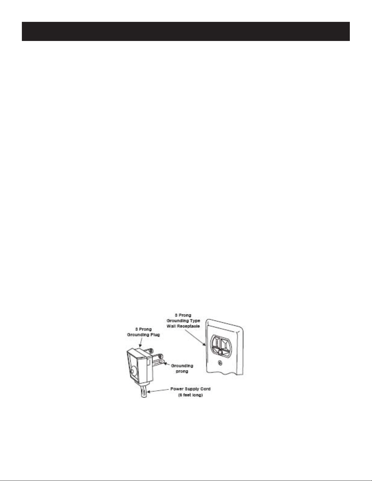
ELECTRICAL CONNECTION
For your personal safety, this air conditioner must be grounded. This unit includes a 3-prong
grounding plug. To minimize possible electrical shock hazard, the cord must be plugged into a mating
3-prong grounding-type outlet and must be grounded according to the National Electrical Code and
all local codes and ordinances. If a mating 3-prong grounding-type outlet is not available, it is your
responsibility to have one installed by a qualifi ed electrician.
2
Page 3
BEFORE INSTALLATION
WARNINGS
Because this unit weights 88-105 lbs., it is recommended that two people install this air conditioner.
•
Inspect the condition of the window where the unit will be installed. Be sure it will support the
weight of the unit.
This appliance must be installed according to all applicable codes and ordinances.
•
Handle the air conditioner with care. Avoid sharp metal fi ns on the front and rear coils.
•
Make sure your air conditioner does not fall during installation.
•
Do not use water collected in the air conditioner for drinking. It is unsanitary.
•
INSTALLATION TIPS
For wood-frame casement windows - it may be necessary to construct a frame using at least 1-inch
•
thick wood with a 15.5-inch wide opening.
For brick or cement building construction - it may be necessary to put a wood stool strip under the
•
air conditioner for mounting purposes.
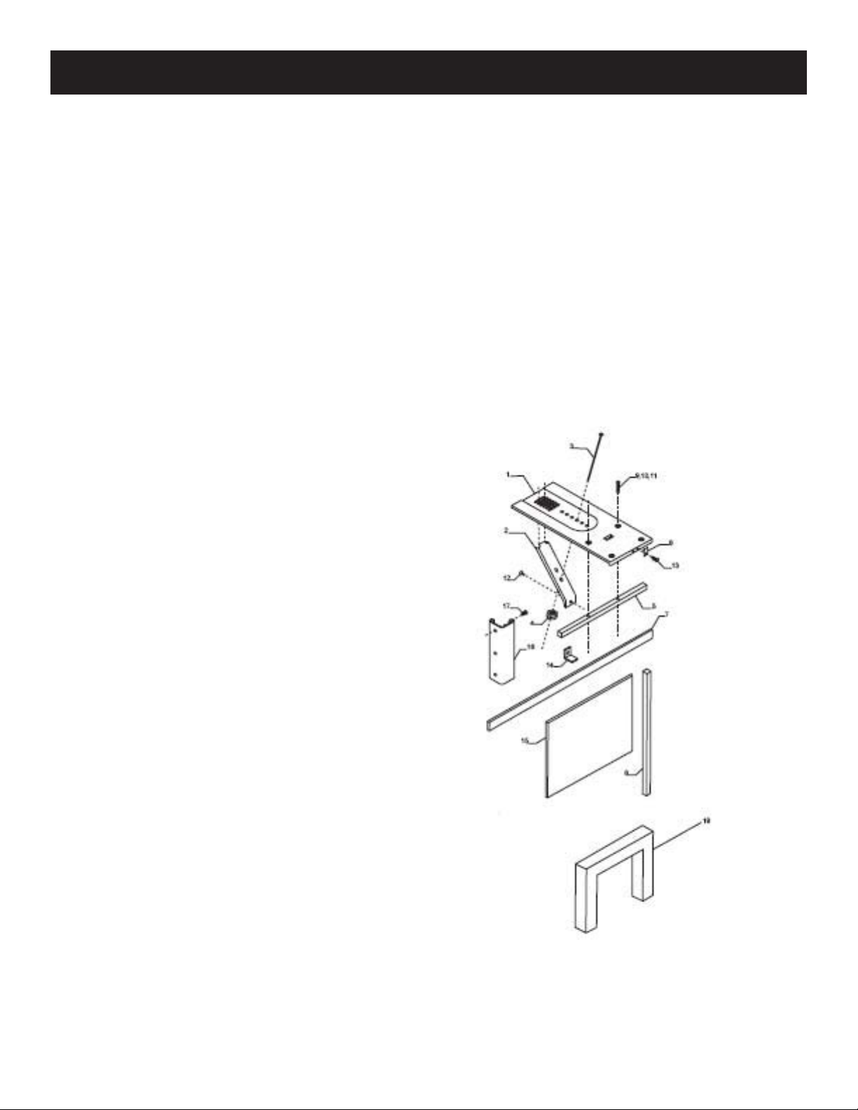
INSTALLATION KIT
Platform (1)
1.
Support brace (1)
2.
Adjustment bolt (1)
3.
Hex fl ange nut - 1/4” (1)
4.
Track seal (1)
5.
Side channel seal (1)
6.
Foam seal strip/Sash seal
7.
Safety bracket (1)
8.
Screw - #10x2-1/2” fl at-head (2) OR
9.
Screw - #10x1-3/4” pan-head (2) OR
10.
Screw - #10x1” pan-head (2)
11.
Screw - #8x3/4” pan-head (6)
12.
Screw - #8-32x3/4” self-threading (7)
13.
Window locking bracket (1)
14.
Plastic window panel (1)
15.
Side channel (2)
16.
Screw - #8x3/8” truss-head (6)
17.
Panel frame/seal assembly (1)
18.
Tools needed: fl at-head screwdriver, Phillips
screwdriver, level, tape measure, fi ne-tooth saw,
electric or hand drill, knife and scissors, pencil
3
Page 4
BEFORE INSTALLATION (cont’d)
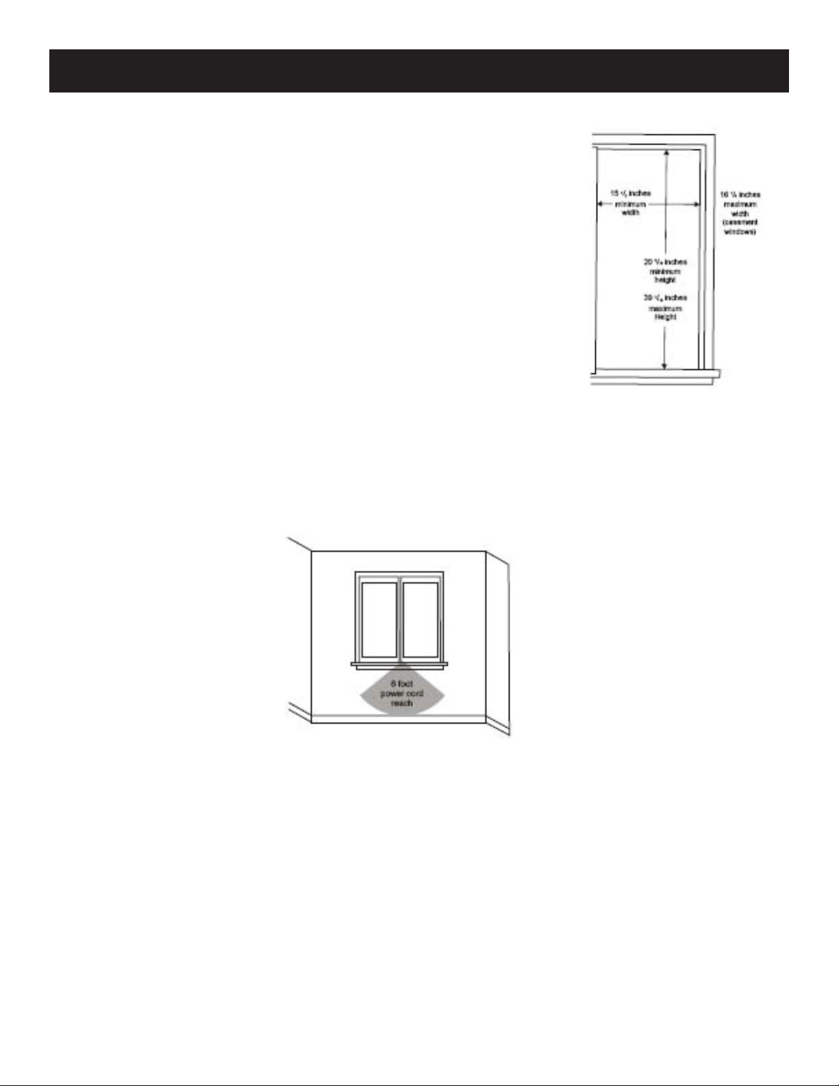
WINDOW SIZE
Be sure your window is the correct size:
15.5” minimum width
•
16.25” maximum width (for casement windows)
•
21.25” minimum height (with window panel retainer)
•
20.3” minimum height (without window panel retainer)
•
39.4” maximum height
•
Note: height measurements must be of a clear opening above mounting
platform. In some cases, due to a variety of stop and track arrangements,
the above dimensions may vary slightly. If necessary, installation can be
made by alternating window jambs.
WINDOW LOCATION
Choose a window that allows the cooled air to fl ow freely and directly into the room you wish to cool.
Remember, it is diffi cult to move air around corners. Also, choose a window that is within 6’ of an
electrical outlet. DO NOT USE AN EXTENSION CORD.
4
Page 5

SLIDING WINDOW INSTALLATION
ATTACH THE SUPPORT BRACE TO THE PLATFORM
Use the adjustment bolt and hex fl ange nut to assemble the
support brace. Choose the slot and adjustment bolt hole that
will create a 45-degree angle between the platform and support
brace. Try to assemble the support brace in the window so
you can determine if the platform will rest properly and at the
correct slope.
MEASURE WINDOW JAMB
Measure and lightly mark a line 8-11/16” from the window
jamb. If any sash stop protrudes more than 1 inch from the side
window jambs, the measurement must be increased accordingly.
Screen and storm window frames may require adjustments.
CENTER PLATFORM
Center the assembled platform on the line with the inside
platform tab pressed against the inside edge of the window
track. Using the platform holes as a guide, mark and drill two
9/64” diameter holes. Drill holes in either the track or the stool.
PROTECTIVE BACKING
Peel off the protective backing from the track seal. Apply seal
to the room side of the window track. The center of the seal
strip should coincide with the previously marked line. The two
previously drilled screw holes should be directly above the seal
strip in the inner track.
SIDING PROTECTION
Securely attach a siding-protection board to the side of the
house. The siding-protection board should be long enough to
span two wall studs.
5
Page 6

SLIDING WINDOW INSTALLATION (cont’d)
PLACE PLATFORM
Place the assembled platform with the platform tab against the
inside window track and attach it to the window jamb. Use the
appropriate length screws.
ADJUST PLATFORM
Adjust the platform so the outside edge is 3/16” lower than the
inside edge. This ensures proper water drainage from the air
conditioner.
LEVEL PLATFORM
Level the platform from side to side. Make sure the window
track is also level. Use the leveling shims, as necessary, to ensure
the air conditioner is level from side to side.
MEASURE WINDOW OPENING HEIGHT
Measure the height of the window opening. Subtract 20.6” and
mark this on the plastic window panel along the longer side.
CLAMP WINDOW PANEL
Clamp the plastic window panel between a board and work
table. Cut around the cutting line with a fi ne tooth saw.
Remove any burrs with a fi le.
FASTEN SIDE CHANNELS
Fasten the side channels to the sides of the air conditioner using
three screws per channel. Make sure the hook ends of the
channels face the back of the unit.
SLIDE PANEL INTO FRAME
Slide the plastic window panel into the panel frame with the
smooth side to the room. Slide the assembled panel frame into
the side channels of the air conditioner cabinet. Make sure
the plastic window panel is fi rmly enclosed on all sides by the
retainer grooves.
6
Page 7

SLIDING WINDOW INSTALLATION (cont’d)
CHANNEL SEAL
Cut the side channel seal into two equal lengths. Remove
protective backing and apply to the read side of the cabinet side
channels, starting just below the assembled panel frame. Pinch
off any excess length so the seal is even with the bottom of the
cabinet side channel.
TO REMOVE THE FRONT
Remove the two front retaining screws from the front frame.
1.
Press fi rmly on each side of the metal case close to the front
2.
of the unit.
While pressing on the sides of the metal case, gently pull the
3.
front out and lift up to release it from the case.
Release the electrical coupler louvers.
4.
Note: DO NOT push or pull on the air direction louvers.
PLACE IN WINDOW
The air conditioner should sit on the assembled platform so the
window panel frame and cabinet side channels are against the
top and side window jambs.
WINDOW SASH
Slide the inner window sash fi rmly against the side of the
cabinet. Make sure not to peel the seal strips from the window
track and cabinet side channels. If the panel frame does not fi t
snugly to the inner window sash, secure the panel frame to the
sash with self-threading screws using the partially plugged holes
in the panel frame.
7
Page 8

SLIDING WINDOW INSTALLATION (cont’d)
SAFETY BRACKET
Hook the safety bracket over the base of the unit and fasten it to
the front of the assembled platform.
Note: the bracket prevents movement after the air conditioner is
in place.
FOAM SEAL
Stuff the foam seal strips/sash seal between the vertical sash and
window glass.
LOCKING BRACKET
Use the window locking bracket to lock the inner window sash
to the base of the outer window sash.
TO REPLACE THE FRONT
Reconnect the coupler plugs and position the exhaust control
through the front. Gently push the front into position on the
cabinet. You will hear it click into place. Replace the retaining
screws to hold the panel in place. DO NOT push or pull the
front panel louvers.
ALTERNATE WINDOW JAMB APPLICATIONS
To install the unit in windows with no fl anges or wood stops on
the top and side jambs, the channels and panel must fi r against
a mating fl ange attached to the window jambs. On each side
of the opening the leading corner of the inner sash becomes the
fl ange. You will need to purchase the angle strip.
8
Page 9

CASEMENT WINDOW INSTALLATION
Open the window the maximum amount to allow cabinet clearance.
•
The crank handle should be removed to allow the platform to be fasted to the jamb.
•
If the window cannot open far enough (more than 15.5”) for the cabinet to clear the window,
•
remove the window entirely by drilling out the rivets. Bolts can serve as the pivots in the future.
To avoid crank handle and window clearance problems, the air conditioner can be installed in a
•
stationary sash section. However, the horizontal mullion and the two glass panels must be removed
before installation.
ATTACH THE SUPPORT BRACE TO THE PLATFORM
Use the adjustment bolt and hex fl ange nut to assemble the
support brace. Choose the slot and adjustment bolt hole that
will create a 45-degree angle between the platform and support
brace. Try to assemble the support brace in the window so
you can determine if the platform will rest properly and at the
correct slope.
PILOT HOLE
Drill a 9/64” diameter pilot hole in the window jamb an equal
distance from each side of the jamb and 3/16” up from the
window sill. If the hole coincides with window lever slot in the
jamb bottom, an additional hole will have to be drilled through
the platform edge and the window jamb to miss this slot.
PROTECTIVE BACKING
Peel off the protective backing from the track seal. Apply seal to
the room side of the window track.
ATTACH PLATFORM TO WINDOW
Screw the assembled platform to the window jamb through the
previously drilled pilot hole using a self-threading screw.
9
Page 10

CASEMENT WINDOW INSTALLATION (cont’d)
ADJUST PLATFORM
Adjust the platform so the outside edge is 3/16” lower than the
inside edge. This ensures proper water drainage from the air
conditioner.
SIDING PROTECTION
Securely attach a siding-protection board to the side of the
house. The siding-protection board should be long enough to
span two wall studs.
MEASURE WINDOW OPENING HEIGHT
Measure the height of the window opening. Subtract 20.6” and
mark this on the plastic window panel along the longer side.
CLAMP WINDOW PANEL
Clamp the plastic window panel between a board and work
table. Cut around the cutting line with a fi ne tooth saw.
Remove any burrs with a fi le.
FASTEN SIDE CHANNELS
Fasten the side channels to the sides of the air conditioner using
three screws per channel. Make sure the hook ends of the
channels face the back of the unit.
SLIDE PANEL INTO FRAME
Slide the plastic window panel into the panel frame with the
smooth side to the room. Slide the assembled panel frame into
the side channels of the air conditioner cabinet. Make sure
the plastic window panel is fi rmly enclosed on all sides by the
retainer grooves.
10
Page 11

CASEMENT WINDOW INSTALLATION (cont’d)
CHANNEL SEAL
Cut the side channel seal into two equal lengths. Remove
protective backing and apply to the read side of the cabinet side
channels, starting just below the assembled panel frame. Pinch
off any excess length so the seal is even with the bottom of the
cabinet side channel.
TO REMOVE THE FRONT
Remove the two front retaining screws from the front frame.
1.
Press fi rmly on each side of the metal case close to the front
2.
of the unit.
While pressing on the sides of the metal case, gently pull the
3.
front out and lift up to release it from the case.
Release the electrical coupler louvers.
4.
Note: DO NOT push or pull on the air direction louvers.
PLACE IN WINDOW
The air conditioner should sit on the assembled platform so the
window panel frame and cabinet side channels are against the
top and side window jambs. The side channels should overlap
the side window jambs equally.
PILOT HOLES
Drill two 9/64” diameter holes in the top window jamb in line with the
partially plugged hole sin the panel frame. Secure the panel frame to the
window jamb with two self-threading screws. If additional holding is
necessary, two screws may be used on the sides of the panel frame.
SCREW-CLEARANCE HOLES
Drill two screw-clearance holes in the cabinet side channels and two 9/64” diameter pilot holes in the
side window jambs. Secure the cabinet side channels to the window jambs with two self-threading
screws. When doing this, be careful not to twist the side channel seals with the screws.
TO REPLACE THE FRONT
Reconnect the coupler plugs and position the exhaust control through the front. Gently push the front
into position on the cabinet. You will hear it click into place. Replace the retaining screws to hold the
panel in place. DO NOT push or pull the front panel louvers.
11
Page 12

© 2006 Sunbeam Products, Inc. doing business as Jarden Consumer Solutions. All rights reserved.
Sunbeam
®
is a registered trademark of Sunbeam Products, Inc. used under license.
Distributed by Petters Consumer Brands, LLC. 4400 Baker Road, Minnetonka, MN 55343.
For service, support and warranty information, visit www.sunbeammajorappliances.com or in the US call 1-866-866-6283.
 Loading...