

Page 1
Page 2
HOW YOUR SUNBEAM
ELECTRONIC AIR CLEANER WORKS
INSTRUCTIONS
A. Remove plastic bag covering the air cleaner.
The air around you is filled with thousands of particles
of air pollution. Some of the pollutants - dust, smoke
B.
and lint are visible to the naked eye, but most of the
pollutants
-
pollen and bacteria, to name a few are
microscopic in size. Your SUNBEAM electronic air
cleaner has been designed to let you enjoy a refreshing experience in clean air living.
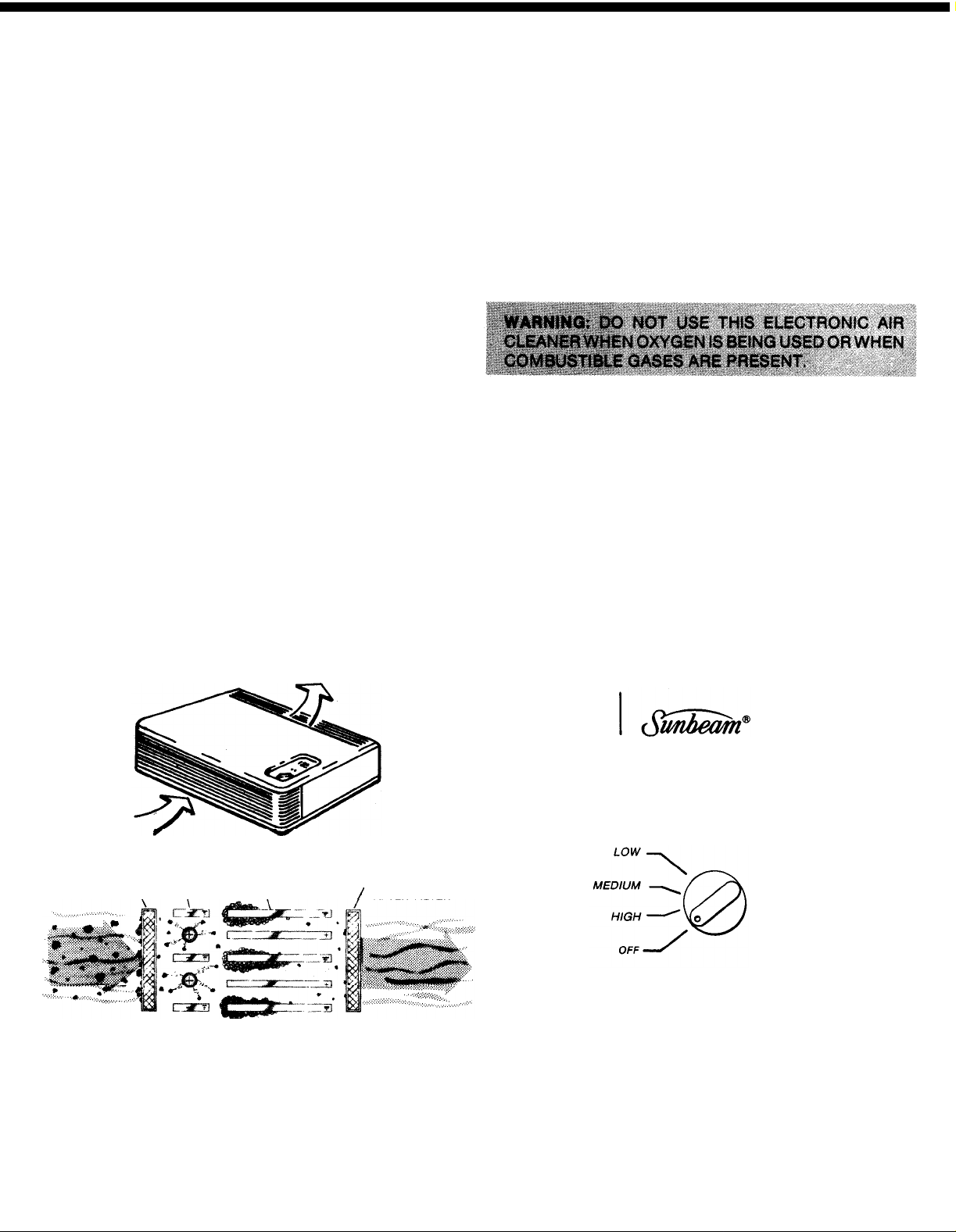
OPERATION
Polluted air enters the air cleaner through the front
(Figure 1). The aluminum pre-filter 1 (Figure 2) on the
inside of the front grill of the unit will help remove some
of the large particles of pollution as dirty air is drawn in.
Once inside the unit, the pollution particles in the dirty
A. Plug the power cord into any standard household
air receive a powerful positive electrical charge as
2
they pass through the ionizing section
The positive
charged particles then enter a collecting section 3
with alternately charged positive and negative (ground)
plates. The particles are repelled from the positive
B. Turn unit on by turning the On/Off switch to the
plates and attracted to the oppositely charged plates
and remain there through natural adhesion until removed by the washing process. The air then passes
through a charcoal filter 4 that helps
remove
household odors. Next the electronically cleaned air
passes back into the room through the top grill.
Select location for air cleaner with electrical outlet
nearby. Remember, air cleaner must be placed so
there is unobstructed free circulation of air into
and out of the unit.
electrical outlet. (See data label on bottom of unit
for electrical specifications and power consumption.
desired blower speed. (Low, Medium or High)
(See Figure 3). Until your unit is adequately
broken in, blower motor speed should be set on
High for one minute initially before switching to
desired setting. Your electronic air cleaner is
designed for continuous operation . . . peak effi-
ciency is obtained if the air cleaner remains on
constantly.
Figure 1
1. PRE-FILTER, 2. ION!ZER
3. COLLECTOR
4. OPTIONAL CHARCOAL
/
AFTER-FILTER
Figure 2
This appliance has a polarized plug (one blade is
wider than the other). As a safety feature, this plug
will fit in a polarized outlet only one way. If the plug
does not fit fully in the outlet, reverse the plug. If it
still does not fit, contact a qualified electrician. Do
not attempt to defeat this safety feature.
Figure 3
NOTE: You may notice an occasional, infrequent
sharp snapping sound coming from the unit. This is
a normal occurrence called “arcing” and results as
large particles of dust are collected in the ionizing-
collecting cell. Should prolonged or continuous arc-
ing occur, the ionizing-collecting cell should be
thoroughly cleaned and dried. (See Cleaning In-
structions).
Page 3
CARE OF CABINET
CABINET:
You should treat the cabinet of your air cleaner as you
would any other piece of fine furniture. Soft cloths and
furniture polish will keep it clean and attractive for
many years.
OZONE
Under normal operating conditions all electrostatic air
cleaners produce minute quantities of ozone as an
incidental by-product, as do televisions and other
electrical appliances. Scientific measurements taken
with the most accurate equipment available show the
range of ozone emitted from a Sunbeam electronic air
cleaner is between
and
l/5
l/20
of the established safe limits of 0.1 ppm. It
.005
and
.02
ppm. This is between
is a negligible figure, in fact, if this amount of ozone is
considered to be harmful, it is dangerous to take an
afternoon walk in the park on a summer day.
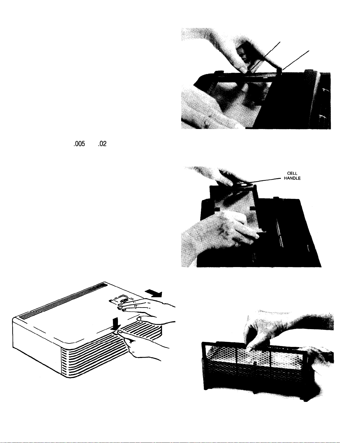
TO REMOVE CELL FOR CLEANING
Figure 5
CELL
HANDLE CELL
/
LOCKING
LATCH
Cell will need cleaning about every four to eight weeks
when air cleaner is in constant use.
A. Turn off unit and unplug from electrical power
source.
B. Remove cabinet top. Cabinet top is easily removed
by pressing down on tab located on top of front
grill (Fig. 4); while pressing down on tab with one
hand, slide cabinet top with other hand slowly
toward front grill about one inch until unlocked.
Cabinet top can now be lifted up and off.
D. Slide pre-filter upward from front of cell (Figure 7).
Figure 6
Figure
4
C. Push cell locking latch (Figure 5) away from cell
of
while lifting cell out
the cabinet using the two
small handles on the top of the cell (Figure 6).
Figure 7
2
Page 4

E. Slide charcoal filter upward from back of cell
(Figure 8).
Figure 8
REPLACEMENT OF CHARCOAL FILTER
ACTIVATED CHARCOAL FILTER HELPS REMOVE
HOUSEHOLD ODORS:
D. After the cell has soaked sufficiently, it should be
shaken vigorously in water until clean. (Figure 9).
Figure 9
E. Thoroughly rinse both sides of cell. If a sprayer is
available, spray with water (Figure 10). Check to
make sure cell plates are clean.
F. Repeat (C) to (E) if necessary.
Washing the charcoal filter with soap and water will
destroy its ability to adsorb odor. However, lint and dirt
build-up can be removed with a vacuum cleaner using
a brush attachment.
Odor adsorption effectiveness will gradually deteriorate and the charcoal filter should be replaced every
three months.
TO CLEAN CELL
NOTE: When handling collecting cell, extreme care
should be taken so fine ionizing wires and metal plates
are not damaged. (Do not wash charcoal filter.)
A. Slide out pre-filter located on front of cell. Rinse
thoroughly with clean warm water. Set aside to dry.
Use dishwashing detergent and the hottest water
B
available to make a good soaking solution.
NOTE: If cell is extremely dirty, spray the cell with a
household cleaning agent such as 409, Fantastik or
Lysol, let soak five (5) minutes before proceeding to
washing instructions.
C. Completely immerse the cell and soak for 20 to 30
minutes.
G. Shake as much water out of the cell as possible
H. Check to make sure cell is thoroughly dry and
TO REPLACE CELL AFTER CLEANING
NOTE: Use label located on top of cell for proper
Figure 10
and allow at least one hour for cell to dry.
replace in unit as described below.
placement of filters into cell and for replacing
cell into unit. Unit will not operate properly if
cell is not replaced correctly.
3
Page 5

A. Slide the pre-filter in the slots provided in the front
of the cell (Figure 11).
Figure 11
B
Slide the charcoal filter in the slots provided in the
back of the cell (Figure 12).
D. Replace cabinet top by positioning over the unit
(Figure 14). Gently slide top forward until top
engages locking tabs (Figure 15). Slide top until
flush with the back of the unit (Figure 16).
Figure 14
Figure 12
C. Using cell handles, align cell with the ribs on the
inside cabinet wall (Figure 13). Gently slide cell
into place.
-
CELL
HANDLE
Figure 13
Figure 15
Figure 16
4
Page 6

Figure 17
NOTE: An occasional “arcing” sound is normal when operating the unit immediately after cleaning the
should stop after a few minutes of operation.
cell
and
TROUBLESHOOTING CHECK LIST
Many times service problems that appear to be major can be solved quite easily. The chart below lists potential problems
and how to correct them. Remember, check the simple things first.
CONDITION
Unit fails
to turn on.
Unit does not
operate at Low speed.
Unit does not
remove pollutants.
WHAT TO CHECK
1. Power cord
2. On/Off Switch
3. Cabinet Top is properly
installed.
4. Cell is properly installed.
Setting of On/Off switch
Ionizer-Collector Cell
WHAT TO DO
1. Plug in power cord.
2. Set On/Off switch for desired blower speed.
3. Refer to Item D, Page 4.
4. To properly install the cell, make sure the
side of the cell with three notches at the
bottom is located next to the switch.
Set On/Off switch on High. Run unit for one
minute and reset On/Off switch at Low speed.
Wash ionizer-collector cell by following the
directions listed in “To Clean Cell”. Operate unit
for
one week, remove the cell and look at the
cell. If operating correctly, the cell will have a
collection of “adhered pollutants” attached to
the plates of the cell.
Unit sparks,
crackles and pops.
Unit still does not
operate properly.
NOTES:
1.
Discoloration of aluminum collector cell plates is normal with use, even after cleaning,
2.
Blowing smoke directly into the front grill is not a test for unit performance.
Ionizer-Collector Cell
Re-check the above points
Wash ionizer-collector cell. Make sure cell is
thoroughly dry.
Have unit serviced.
5
Page 7

REPLACEMENT
PARTS
Key Number Part Number
1
2
347166-001
342480-001
Description
Cabinet Top
Pre-Filter
MODEL NO.
2585
SUNBEAM TABLE TOP
ELECTRONIC AIR CLEANER
3
4
6
442415001
6571
Ionizer-Collector Cell
Charcoal Filter (Set of
2)*
Page 8

a@
I
MODEL 2585
OWNER’S
MANUAL
TABLE TOP ELECTRONIC
AIR CLEANER
The Model Number will be found on the name plate attached to the
bottom of the SUNBEAM Electronic Air Cleaner. Always mention the
Model Number when requesting service or repair parts for your SUNBEAM Electronic Air Cleaner.
WHEN ORDERING REPAIR PARTS, ALWAYS GIVE THE
INFORMATION:
HOW TO ORDER
1. Part Number
2. Part Description
3. Model Number 2585
.
4. Name of Item - SUNBEAM Table Top
Electronic Air Cleaner
REPAIR PARTS
@Sunbeam, @Sunbeam-Oster Household Products, Distributed by Sunbeam-Oster Household Products, Schaumburg, il
Committed
FORM # 147102401
To Our Environment . . . Printed on Recycled Paper
FOLLOWING
60173
(1
 Loading...