

TM-8129000504
REMOTE CONTROL UNIT
for
RT-90008 HF/SSB
TRANSCEIVER
RCU-93108
OPERATION AND MAINTENANCE
MANUAL
fj®
SUNAIR 3005 Southwest Third Avenue, Fort Lauderdale, Florida 33315-3312
WARRANTY POLICY
GROUND AND MARINE PRODUCTS
(
Sunair Electronics warrants each equipment manufactured by
material or workmanship, under normal use for the lesser of one
installation or
Sunair will repair or replace, at its option, any defective equipment or component of the
equipment returned to
No
reimbursement will
This warranty
misuse, abuse, accident, water damage or other neglect, or has its serial number defaced
or removed. (
THIS WARRANTY
EXPRESSED
ABILITY
of Sunair
consequential or other damage or expense whatsoever therefore or by any reason thereof.
15 months from date of shipment
it
at its factory, transportation prepaid, within such warranty period.
be
made for non-factory repair charges.
is
void
if
OR
FITNESS
shall
equipment
IS
ESPECIALLY
OR
IMPLIED, INCLUDING ANY IMPLIED WARRANTY OF MERCHANT-
FOR
A PARTICULAR PURPOSE. The obligation and responsibility
be
limited to that expressly provided herein and Sunair shall not
is
modified or repaired without authorization, subject to
IN
LIEU OF ANY AND ALL OTHER WARRANTIES
by
Sunair.
it
to be free from defects
(1)
year from the date of
be
liable for
in
Sunair reserves the right
equipment without obligation
theretofore manufactured.
,,®
to
make changes
SUNAIR ELECTRONICS, INC.
in
design or additions to or improvements
to
install such additions or improvements
in
equipment
in
its
(
0
Ql
~
Mtc/AUX
~I
e
Oo
e
K!Y
~
@
P:AI.A.T
I
I
QJ
[!]
0
000
000
I I
~~~
II:U:-11
I
0
I I
D
D
0
~~o
OFFo
RCU-9310
REMOTE CONTROL
UNIT
f;i\jj
El
~
[';ij@J~
"
"
rrm[;JEJ
~.l:'
0
I
RCU-8310
l
0
~
e
e
OPERATION
AND
MAINTENANCE
MANUAL
FOURTHEDITIONFEBRUARY28, 1997
Page change
Page change
1:
03/24/99
2:
08/26/99
PRODUCT SERVICE:
In case of difficulty please contact the Sunair
Product SeNice Department, between the hours
of
8:00 AM and 5:00
Product SeNice Dept.
Sunair Electronics,
3101
Ft.
Lauderdale, FL 33315-3389
PM
or write to:
Inc.
SW Third Avenue
U.S.A.
Telephone:
Fax:
E-Mail:
(954) 525-1505
(954) 765-1322
techsupport@ sunairhf.com
TRAINING:
Sunair offers training programs of varying
lengths
maintenance
equipment. For details please contact the
Product Support Department.
covering
of all
operation, service, and
Sunair
manufactured
(
(
I SUNAIR RCU-9310 I
f
I
r
, I
Section
II
TABLE
GENERAL INFORMATION
1.1
1.2
1.3 GENERAL DESCRIPTION
1.4 TECHNICAL SPECIFICATIONS
1.5 ENVIRONMENTAL SPECIFICATIONS
1.6 EQUIPMENT SUPPLIED
1.7 OPTIONS AVAILABLE
INSTALLATION
2.1
2.2
2.3 RETURN OF EQUIPMENT TO FACTORY
SCOPE OF MANUAL
PURPOSE OF EQUIPMENT
GENERAL
UNPACKING
of
Description
AND
INSPECTION
CONTENTS
Page
1-1
1-1
1-1
1-2
1-2
1-3
1-3
2-1
2-1
2-1
2.4 GENERAL INSTALLATION
INFORMATION
2.4.1
2.4.2 BASE STATION INSTALLATION
2.4.3 RACK INSTALLATIONS
Ill OPERATION
3.1
3.2
GENERAL
PRIMARY OPERATIONS
3.2.1
3.2.2
3.2.3
3.2.4 ANTENNA
3.2.5 MANUAL
3.2.6
AND
MOUNTING
2-2
GENERAL INSTALLATION
REMOTE TRANSCEIVER SET
AND
TRANSMIT POWER 3-3
ESTABLISHING
TRANSMIT TUNING 3-6
TUNING 3-6
PANEL LIGHTING 3-7
AN
OPERATING FREQUENCY 3-5
COUPLER TUNING 3-6
UP
FOR
MODE,
2-2
2-9
2-9
3-1
3-3
AGC
3.2.7
3.2.8 MANUAL CHANNEL
OPERATING WITH PRESET CHANNELS 3-7
SCANNING 3-8
I SUNAIR RCU-9310 I
Section
3.3
TABLE
3.2.9 LOADING PRESET CHANNEL FREQUENCIES
3.2.10 BFO OPERATION
EQUIPMENT SET UP
3.3.1
3.3.2
3.3.3
3.3.4
3.3.5 TIME DISPLAY
3.3.6 'I/O' PORT SET UP
3.3.7
3.3.8
BITE (Built in Test Equipment)
3.3.1.1
3.3.1.2
METER FUNCTIONS
SPEAKER ON/OFF FUNCTION
'MHz' or 'kHz' FREQUENCY DISPLAY
ADDRESS AND SOFTWARE REVISION LEVEL
'CW
of
CONTENTS
Description
REMOTE
TRANSCEIVER
KEY AND FILTER OPTIONS
CONTROL
TEST
(Cont.
UNIT
SELF-TEST
(REMOTE
BITE)
..
)
(LOCAL
BITE)
Page
3-10
3-12
3-13
3-13
3-14
3-15
3-17
3-19
3-20
3-20
3-22
3-25
3-26
(
\
3.4
3.3.9
ADVANCED OPERATIONS
3.4.1
3.4.2
3.4.3
3.4.4
3.4.5
3.4.6
3.4.7
3.4.8
LINE AUDIO SELECTION
RECEIVER SCANNING
AUTOMATIC LINK ESTABLISHMENT (ALE)
PROGRAMMING
3.4.2.1
3.4.2.2
AUTOMATIC LINK ESTABLISHMENT (ALE)
OPERATION
SOUNDING
NET
3.4.5.1
ALL CALL
BREAK LINK COMMAND
OPTIONS
GENERAL
ESTABLISHING
CALL
PLACING A NET-CALL
ALE-I
D's
3-27
3-28
3-28
3-31
3-31
3-32
3-36
3-41
3-44
3-44
3-46
3-47
3-48
(
3.4.8.1 L
3.4.8.2
ii
YNCOMPEX
DATA
FILTER
3-48
3-49
(
I SUNAIR RCU-9310 I
Section
IV
TABLE
3.4.8.3 RADIO SECURITY
3.4.8.4 PRE-SELECTOR
THEORY
4.1
4.2 REMOTE CONTROL UNIT
OF
OPERATION
REMOTE CONTROL UNIT-TRANSCEIVER INTERFACE
AND INTERACTION
4.2.1 FRONT PANEL ASSEMBLY
4.2.2
CPU ASSEMBLY 3A2A1 4-3
4.2.2.1 GENERAL
4.2.2.2 MICROPROCESSOR U2
4.2.2.3 ERASABLE PROGRAMMABLE READ-ONLY
4.2.2.4 ELECTRICALLY ERASABLE PROGRAMMABLE READ
of
CONTENTS (Cont...)
Description
MEMORY (EPROM)
3A1
U13 and U14
Page
3-49
3-50
4-1
4-1
4-3
4-3
4-3
4-3
v
FAULT
5.1
5.2
5.3
ONLY MEMORY (EEPROM)
4.2.2.5 STATIC RANDOM ACCESS MEMORY (SRAM) U3
4.2.2.6 OPTIONAL SMART WATCH U14(A)
4.2.3 OPTOCOUPLER ASSEMBLY 3A2A
4.2.4
4.2.5 1/0 ASSEMBLY 3A2A3
4.2.6 POWER SUPPLY ASSEMBLIES 3A3, 3A3A
GENERAL
DISASSEMBLY
5.2.1 TOP
TEST
5.3.1 PRELIMINARY
AUDIO/REMOTE AUDIO ASSEMBLIES
3A2A2/3A2A4
and 3A3A2
ISOLATION/MAINTENANCE
OR
BOTTOM COVER REMOVAL
SETUP
AND
US
1A
REPAIR
1
4-4
4-4
4-4
4-4
4-4
4-5
1,
4-6
5-1
5-1
5-1
5-1
5-1
5.4
BITE
5.4.1 PRELIMINARY
5.4.2 COMMON MODULES
5-1
5-1
5-4
iii

I SUNAIR
RCU-9310
I
Section
5.5
5.6
5.7
TABLE
5.4.2.1
5.4.2.2 CPU FAULT 5-4
5.4.2.3
5.4.2.4 AUDIO FAULT 5-5
5.4.2.5 POWER SUPPLY FAULT 5-6
TROUBLESHOOTING WITH SELF-SURVEILLANCE BITE 5-6
5.5.1
5.5.2
TEST EQUIPMENT REQUIRED OR EQUIVALENT 5-16
TEST AND ALIGNMENT 5-16
5.7.1
5.7.2
AC POWER SUPPLY 5-6
INSTALLATION OF NEW BACKLIGHTING DEVICES
FOR
TRANSMIT REMOTE AUDIO 5-16
RECEIVE REMOTE AUDIO 5-20
of CONTENTS (Cont...)
Description Page
FRONT PANEL FAULT 5-4
110
FAULT 5-5
FRONT PANEL LCD'S 5-12
(
5.8
5.7.3 SOFTWARE SWITCH SETTING CHECKS
SCHEMATICS AND PARTS LISTS 5-25
5-23
(
iv
(
I SUNAIR RCU-9310 I
ADDR
AGC
ALC
AM
AME
AMP/AMPL Amplifier
ARQ
AUD
AUTO Automatic
AUX
BAUD
BELL
BFO
BITE
BAD
CH
CLR
CMOS
CPLR
CPU
CW
dB
dBm
DSBSC
DSP
DUART
EEPROM
EPROM
EMI
ENTR
FAX
FEC
FREQ
FSK
FWD
GAP Group
HF
Hz
IC
IF
1/0
IONCAP
kHz
kW
ISB
LCD
LCL
LED
LK
LO
LP/LPX Lincompex
LRU
LSB
LT Light
Address
Automatic
Automatic
Amplitude
Amplitude
Automatic
Audio
Auxiliary
A variable unij of data transmission
per
U.S.
Beat
Built In Test Equipment
Board
/CHAN
/CHLJCHN
Clear
Complementary
Coupler
Computer
Carrier
Decibel
Decibels
Double
Display
Dual
Electrically
Only
Electrically
Electromagnetic
Enter
Facsimile
Forward
Frequency
Frequency Shift
Forward
High
Hertz
Integrated Circuit
Intermediate Frequency
lnpui/Output
Ionospheric Communications Analysis
and
Kilohertz
Kilowatt
Independent
Liquid
Local
Light Emitting
Link
Local
Lowest
Lower
Gain
Level
Modulation
Modulation
Request
second)
Telephone standards
Frequency
Wave
referred
Sideband
Asynchronous
Memory
Programmable
Error
Frequency
Prediction
Crystal
Oscillator
Repairable
Sideband
TABLE
Control
Control
Equivalent
Oscillator
Channel
Metal
Oxide
Semiconductor
to 1 milliwatt across
Suppressed Carrier
Receive/Transmit
Erasable
Correction
Sideband
Display
Diode
and
Radiation
Keying
Unit
Programmable
Read
Interference
of
speed
Only
ABBREVIATIONS
(bits
600
ohms
Read
Memory
LVL
MAN
M
MED
MHz
MIC
MIL-STD
MNL
ms
MTTR
MTR
NAR
0.0.
PA
PC
PEP
PLL
P/N
PNL
POSTSL
PRESEL
PTT Push-To-Talk
PWR
RCV/RX
REFL
REV
RF
RFI
RFL
RMT
RS232
RS422
RS485
RlTY
SEL
SLO
S
SPKR
SPLX
SRAM
SSB
TCXO
TGC
THO
TTL Transistor Transistor Logic
TX/XMT Transmit
USB
UTC
VCO
VHF
VRMS
VSWR
W Watt
WPM
• Asterisk indicates function selected
Level
Manual
CH
Manual
Medium
Megahertz
Microphone
Manual
Millisecond
Mean
Meter
Narrow
Olive
Power
Printed
Peak
Phase-Locked
Part
Panel
Power
Receive
Reflected
Revision
Radio
Radio
Reflected
Remote
Computer
Computer
maximum
Computer control, hardwired for multiple users
Radio
Select
Slow
MTR
Signal Strength Meter
Speaker
Simplex
Static
Single
Temperature Controlled Crystal Oscillator
Transmit
Total
Upper
Universal
Voltage Controlled Oscillator
Very
Volts
Voltage standing
Words
Channel
Milijary Standard
Time
To
Repair
Drab
Amplifier
Circuit
Envelope
Number
Post-Selector
Pre-Selector
Frequency
Frequency
Teletype
Random
Sideband
Harmonic
Sideband
High
Root
Per
Power
Loop
control,
control,
Access Memory
Gain
Control
Distortion
Time
Frequency
Mean
Minute
Interference
hardwired upto50feetmaximum
Square
Wave
hardwired
Ratio
up
to
4000
feet
v
I SUNAIR RCU-9310 I
Section
II
LISTING
Description Page
INSTALLATION
Figure 2.4.1.1 RCU-9310 Outline Dimensions and Connector
Locations. 2-4
Figure 2.4.1.2 Interconnection
Unit and RT-9000 Transceiver. 2-5
Figure 2.4.1.3
Wiring Diagrams.
Figure 2.4 .1.4
Wiring Diagram. 2-7
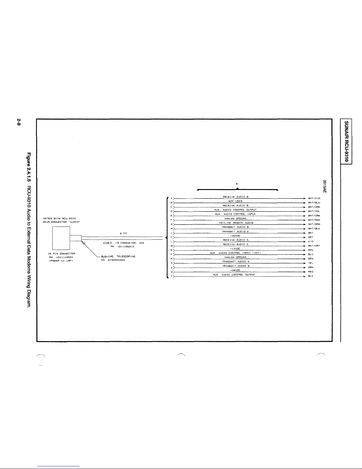
Figure 2.4.1.5
Diagram. 2-8
Figure 2.4.3
FSK, RS-232, RS-422,
RCU-9310 Remote Audio to RT-9000 Audio
RCU-9310 Audio to External Data Modems Wiring
Installation
of
of
of
RCU-9310
FIGURES
RCU-931 0 Remote Control
or
RS-485
in
Equipment Rack.
(
2-6
2-9
Ill
OPERATION
Figure 3.1.1 Front Panel Controls for the RCU-9310.
Figure 3.1.2
Figure
Figure 3.2.2
Figure 3.2.5
Figure 3.2. 7
Figure 3.2.8 RCU-931
Figure 3.2.9.1
Figure 3.2.9.2
Figure 3.2.10
Figure 3.3.1.1
Figure 3.3.1.2
Figure 3.3.2.1
Figure 3.3.2.2
3.2.1
Operational Display Information Location.
RCU-9310 Remote Control Display Screens. 3-4
RCU-9310 Operating Controls. 3-5
RCU-9310 Operating Controls. 3-7
RCU-9310 Operating Controls. 3-8
0 Operational Controls. 3-9
RCU-9310 Channel Loading Controls.
RCU-931
RCU-9310 Displays,
RCU-9310 Feature Menu, BITE Selection. 3-13
RCU-9310 BITE Submenu. 3-14
RCU-931 0 Operational Displays.
RCU-9310 Feature Menu Select Display. 3-17
0 'Feature Display'.
with BFO Enabled. 3-12
3-1
(
3-2
3-10
3-11
3-17
Figure 3.3.2.3
Figure 3.3.2.4
Figure 3.3.3
vi
RCU-9310 Feature Menu Select Display.
RCU-9310 Feature Menu Select Display.
RCU-9310 Feature Menu Select Display. 3-19
3-18
3-18
(
I SUNAIR RCU-9310 I
Section
LISTING
Figure 3.3.4 RCU-931 0 Operating Controls. 3-20
Figure 3.3.5.1 Feature Menu Display. 3-20
Figure 3.3.5.2 Time Display
Figure 3.3.5.3 Time Display.
Figure 3.3.5.4 'Set-Time' Display. 3-22
Figure 3.3.6.1 RCU-931 0
Figure 3.3.6.2 Feature Menu
Figure 3.3.6.4 Port 'A' Conditioning Menu. 3-24
Figure 3.3.6.5 Baud Rate
Figure 3.3.6.6 Baud Rate Selection Menu
Figure 3.3.6.7 Baud Rate
Figure
3.3.7.1
Address
of
FIGURES (Cont.
Description Page
and
Time Set Display.
110
Port Connector. 3-22
Display
Display. 3-24
Selection Menu
and
Revision Level Display. 3-25
of
Port 'A' Selection Menu. 3-23
1.
2.
..
)
3-21
3-21
3-24
3-25
Figure 3.3.7.2 Feature Menu for
Figure 3.3.8 Feature
Figure 3.3.9.1 RCU-9310 Feature Menu Select Display. 3-28
Figure 3.3.9.2 Line Audio Selection Menu Display. 3-28
Figure 3.4.1.1 Operational Display for Channelized Mode. 3-29
Figure 3.4.1.2 Feature Menu
Figure 3.4.1.3 Feature Menu
Figure 3.4.1.4 Feature Menu Display for 'SCAN LOAD' Select
Figure 3.4.2.2.1 RCU-9310 Feature Menu Display. 3-32
Figure 3.4.2.2.2 Feature Menu
Figure 3.4.2.2.3 RCU-9310 Display for 'SLOT
Figure 3.4.2.2.4 RCU-9310 Display for 'SELF ID' Programming.
Figure 3.4.2.2.5 Feature Display for 'CALL ID' Select
Figure 3.4.3.1 Operational Display for 'ALE' Function.
Figure 3.4.3.2 ALE
Menu
Calling Menu.
Selection of Address. 3-26
Display for Selection
Display for 'SCAN' Select
Display for 'SCAN' Function. 3-30
Display for 'ALE-ID' Select
of
'CW' Options. 3-27
Key.
Key.
PS'
Programming.
Key.
Key.
3-29
3-30
3-33
3-33
3-34
3-35
3-37
3-37
Figure 3.4.3.3 Feature Display for 'Select Group'.
Figure 3.4.3.4 Operational Display for 'CALL ID' Selection.
Figure 3.4.3.5 Operational Display of the Station Being Called.
3-38
3-39
3-39
vii
I SUNAIR RCU-9310 I
Section
LISTING of FIGURES (Cont.
Description
Figure 3.4.3.6 Operational Display of
Figure 3.4.3.7 Operational Display
Figure
Figure 3.4.4.2 Sounding
Figure 3.4.4.3 Operational Display at Sounding Station.
Figure 3.4.4.4
Figure 3.4.4.5 Sounding Timer Menu.
Figure
Figure
Figure 3.4.8.
Figure 3.4.8. 1.2 Lycompex
3.4.4.1
Sound.
3.4.7.1
3.4.8.1
ALE
Calling Menu.
Menu.
Operational Display
Break Link Keys. 3-48
'SECURE' Feature
1.1
Lycompex Feature
Control Feature
Link
with
Station
on
Called Station after a
on
Network Stations Receiving
Menu.
Menu
Display. 3-48
Menu
..
)
Being
Display. 3-49
Called.
Link.
Page
3-40
3-41
3-41
3-42
3-42
3-43
3-43
3-48
IV
v
Figure 3.4.8.5. 1 Feature
THEORY
Figure
FAULT
Figure
Figure
Figure
Figure
Figure
Figure 5.4.2.2
Figure 5.4.2.3
Figure 5.4.2.4 Removal/Replacement of 1/0 3A2A3 or
OF OPERATION
4.1
RCU-9310 Remote Control Unit Block Diagram.
ISOLATION/MAINTENANCE AND REPAIR
5.2.
1.1
Top/Bottom
5.4.1.1
5.4.
5.4.1
5.4.2.1
Assemblies Locations. 5-9
1/0 3A2A3. 5-10
FSK 3A2A3A
RCU-9310 Feature Menu, BITE Selection.
1.2
RCU-931
.3
Top View
Major Assembly Locations. 5-8
Removal of Front and Rear Panel and Major
Removal/Replacement
Menu
0 BITE Submenu.
RCU-931 0 LRU
1.
Display for Pre-selector Selection. 3-50
and
Card Cage Covers Removal.
'Fault Indicators'. 5-5
of
CPU
3A2A 1 and
(
4-2
5-2
5-3
5-3
5-11
Figure 5.5.2. 1 Removal
Assembly. 5-13
Figure 5.5.2.2
viii
Removal
and
Installation of Front Panel
and
Installation of
LCD
PC
(
Assembly. 5-14
I SUNAIR RCU-9310 I
LISTING of FIGURES (Cont.
Section Description
Figure 5.5.2.3 Installation of Backlighting Devices. 5-15
Figure 5.7.1.1
5.
Figure
Figure
Figure
Figure 5.7.2.2 Receive Path Audio
Figure
Figure
Figure 5.8.2
Figure 5.8.3
7.1.2 Top View RCU-931 0 Alignment Adjustment
Locations. 5-18
5.
7.1.3 Transmit Path Audio
5.
7.2.1
5.8
5.8.1
and Connector
RCU-931
RCU-931
RCU-9310 Assemblies and Subassemblies. 5-25
Final Tested RCU-931
PC
Assembly, Front Panel 3A 1A
PC
Assembly, Mother Board 3A2A5, page 1 of
0 Stand Alone Audio Test Set
0 Stand Alone Audio Test Set
Kit.
A.
A.
0,
Chassis Assembly
1,
page 1 of
..
)
Up.
Up.
3A3,
6.
4.
Page
5-18
5-19
5-21
5-22
5-27
5-28
5-34
Figure 5.8.4
Figure 5.8.5
page 1
Figure 5.8.6
Figure
Figure 5.8.8
Figure 5.8.9
Figure
Figure
Figure 5.8.12
Figure 5.8.13
5.8. 7 PC
5.8.1
0 AC/DC Power Supply Chassis and Interconnect
Diagram, page 1 of
5.8.11
page 1 of
page 1 of
page 1 of
PC
Assembly, CPU 3A2A
PC
Assembly, OPTOCOUPLER 3A2A1A1,
of
3.
PC
Assembly, Audio 3A2A2, page 1
Assembly, Audio Remote 3A2A4, page 1 of
PC
Assembly, 1/0 Board 3A2A3, page 1 of
PC
Assembly, FSK Modem 3A2A3A1, page 1 of
1.
PC
Assembly, 28V Regulator, 5 Amp 3A3A
2.
PC
Assembly, 5/12V Regulators 3A3A2,
2.
PC
Assembly, Audio Connectors 3A3A3,
2.
1,
page 1 of
of
8.
9.
4.
1,
2.
2.
5-38
5-46
5-49
5-58
5-60
5-64
5-67
5-68
5-70
5-72
ix
(
ITHIS
PAGE
INTENTIONALLY
LEFr
BLANK.I
(
(

I SUNAIR RCU-9310 I
SECTION I
GENERAL INFORMATION
1.1
SCOPE
This manual contains information necessary to install, operate, and maintain the RCU-931 0 Remote Control Unit.
Installation information is
Maintenance and Repair Procedures are in Section
IV.
configurations,
1.2 PURPOSE OF EQUIPMENT
OF
MANUAL
in
Section
unless otherwise stated in the text or illustrations.
II.
Operating Instructions are in Section Ill. Theory
V.
Information in this manual applies to all equipment
of
Operation is in Section
The RCU-931 o Remote Control Unit is designed to provide complete operational control
RT-9000
The RCU-9310
selecting the transmission mode and power level; establishing operating frequencies; automatically tuning the
transmitter and associated antenna
frequency
The RCU-9310 also enables the remote operator to perform several non-operational, periodic, functions related
to equipment setup and maintenance. Diagnostic tests--to the lowest repairable unit (LRU) -- can be selectively
executed
keying speed and filtering options; connection of external devices to the transceiver's audio input and output lines;
local I/O
metering at the remote
In
addition, the RCU-931 o allows the remote operator to access and use the transceiver's advanced automated
functions: receiver scanning
Establishment (ALE) operations; "sounding" (broadcasting to selected stations in a predefined network); and
"network call" (broadcasting to all stations in a network).
Transceiver.
allows
channels.
on
both the transceiver and the remote control unit itself. Other functions include: selection
port conditioning; transceiver memory dump (i.e., clearing all preprogrammed channels); and transceiver
an
operator at a remote site to access and perform all transceiver primary functions:
coupler; manual tuning; and loading, scanning, and operating with preset
control panel.
of
preprogrammed channels; programming and execution of Automatic Link
of
a remotely-located
of
CW
1.3 GENERAL DESCRIPTION
The RCU-931 o
package makes the
the service technician in mind.
modularized plug-in assemblies
located on the assemblies allow the technician to pinpoint faulty modules immediately. The RCU-931 0 is
lightweight for its capability, weighing only 20 pounds. Available in Olive Drab (OD)
compatible with most radio station color schemes. (If a particular color other than
Sunair Marketing Department for information concerning changes
the
is
intended for use on table tops
RCU-9310 adaptable to various environments. Internally, the RCU-9310 is designed with
Built-in test equipment (BITE), with descriptive front-panel readouts, and .
rnake the MTTR (Mean Time To Repair) less than fifteen (15) minutes. LEDs
or
in base station 19-inch rack installations. However, its rugged
or
Grey, the RCU-931 0 is
ODor
Grey is required, contact
to
the standard colors.)
The RCU-9310 has a simple, easily understood, front panel that duplicates the functions
Transceiver. Firsttime users can operate the equipment without extensive training. The wide screen liquid crystal
display
Channel, Mode, BFO, AGC, Power, Local
selectively indicates signal strength, forward RF power, reverse RF power and Remote transmit and receive audio
(LCD)
is
continuously updated by the microprocessor with operational status such as Frequency,
of
the RT-9000
or
Remote Control. The LCD also contains a bar graph meter which
1-1
I SUNAIR RCU-9310 I
The built-in-test routines include power amplifier and antenna coupler status in plain English messages which
appear in the
The softkeys
operating features not found on the front
1.4 TECHNICAL SPECIFICATIONS
REMOTE INTERFACE: RS232/422/485 FSKTone.
TRANSCEIVER INTERFACE: Transmit and receive audio, 0 dBm adjustable into 600 ohms.
BITE: Fault isolated to module level (LRU), descriptive readout on front panel and individual module indication.
display. Softkeys and a softkey menu LCD display selected options such as Time,
also provide access to remote control configuration, meter selection, speaker control and other
panel keyboard.
I
NOTE:
I Must be hardwired between RCU-931 0 and RT -9000(A) for mode selected.
CW
Filter, etc.
(
INPUT POWER: +26
AUDIO OUTPUT: 5 Watts into internal speaker< 5% THO; Two selectable lines, at
600 ohms; Headset, low impedance.
SQUELCH: Syllabic.
AUDIO INPUT: Microphone, aux. connector, and two selectable 600 ohm lines at -20 dBm to +10 dBm.
SIZE:
WEIGHT: (KG):
CONSTRUCTION: Modular plug-in
(CM):
(INCHES) 5.96H X 17.83W X 10.25L
(LBS): 20
VDC ±15%; 120/240VAC ±15%;
15.2H X 45.3W X 26.04L.
9.1
assemblies.
AC/DCAuto
Changeover.
·20
dBm to
+1
0 dBm into
1.5 ENVIRONMENTAL SPECIFICATIONS
TEMPERATURE:
HUMIDITY: 100%
-30'C
to +50'C.
at 50'C.
(
RAIN: MIL-STD-8100, Method 506.2.
SHOCK: MIL-STD-8100, Method 516.3.
VIBRATION: MIL-STD-8100, Method 514.3.
Page change
1-2
2:
8/26/99
(
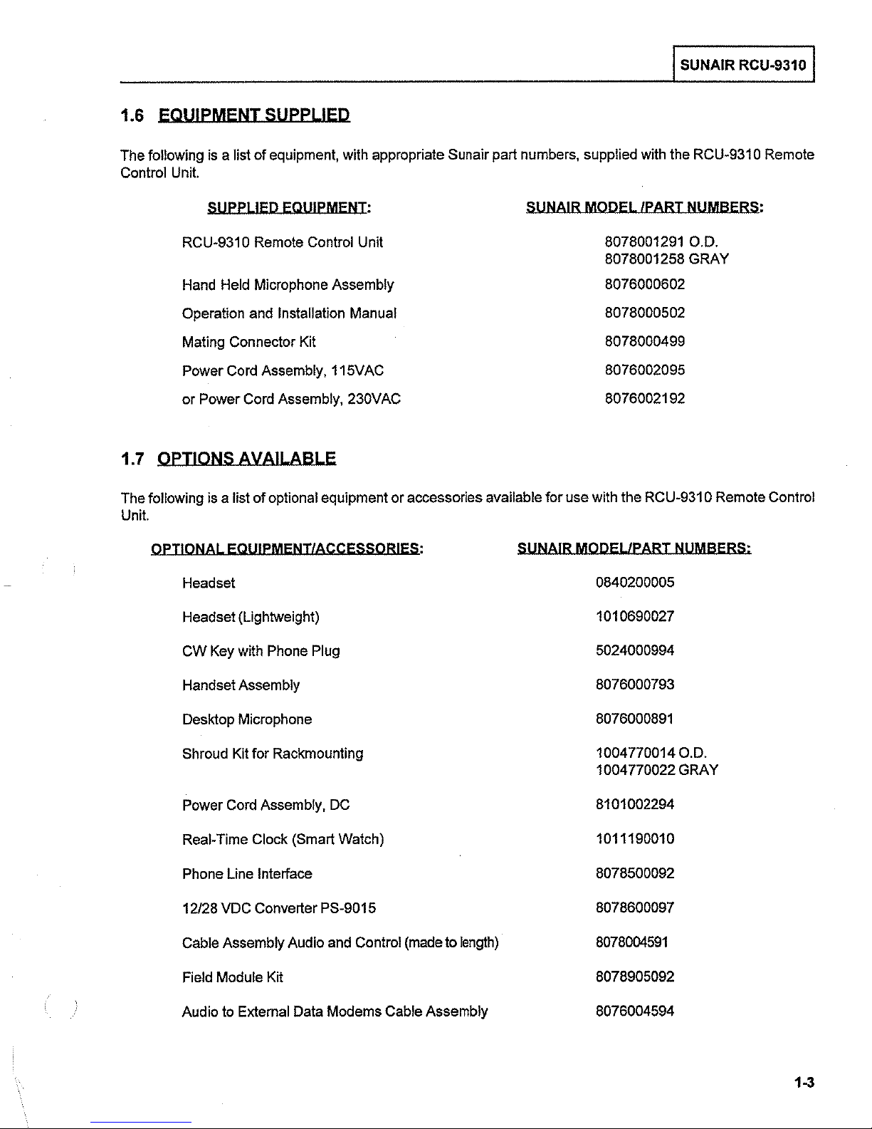
1.6 EQUIPMENT SUPPLIED
I SUNAIR RCU-9310 I
The following
Control
is a Jist
Unit.
SUPPLIED EQUIPMENT:
RCU-931
Hand
Operation
Mating Connector Kit
Power
or Power
of equipment, with appropriate Sunair part numbers, supplied
0 Remote Control Unit
Held
Microphone Assembly
and
Installation Manual
Cord
Assembly, 115VAC
Cord
Assembly, 230VAC
with
the
SUNAIR MODEL /PART NUMBERS:
8078001291
8078001258 GRAY
8076000602
8078000502
8078000499
8076002095
8076002192
1.7 OPTIONS AVAILABLE
following
The
Unit.
OPTIONAL EQUIPMENT/ACCESSORIES: SUNAIR MODEL/PART NUMBERS:
is
a list of optional equipment or accessories available for use with the
RCU-931
RCU-931
O.D.
0 Remote Control
0 Remote
Headset 0840200005
Headset (Lightweight) 1010690027
Key
with
CW
Handset Assembly 8076000793
Desktop Microphone
Shroud
Power
Real-Time Clock (Smart Watch) 1011190010
Phone Line Interface 8078500092
12/28
VDC
Assembly Audio
Cable
Field Module Kit 8078905092
Phone
Kit
for Rackmounting 1004770014
Cord
Assembly,
Converter PS-9015 8078600097
Plug
DC
and
Control
(made
to
length)
5024000994
8076000891
1004 770022 GRAY
8101002294
8078004591
O.D.
to
Audio
External
Data
Modems Cable Assembly 8076004594
1-3
I SUNAIR RCU-9310 I
(
lrHIS
PAGE INTENTIONALLY LEFT BLANK.!
(
1-4
(
I
I
SUNAIR
RCU-9310 I
SECTION
II
INSTALLATION
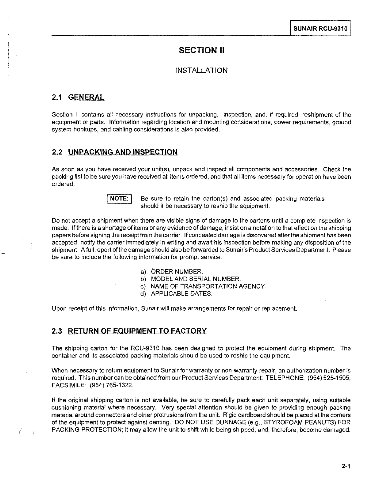
2.1
GENERAL
Section
equipment
system hookups, and cabling considerations is also provided.
II
contains all necessary instructions for unpacking, inspection, and,
or
parts. Information regarding location and mounting considerations, power requirements, ground
if
required, reshipment
of
the
2.2 UNPACKING AND INSPECTION
As soon as you have received your unit(s), unpack and inspect all components and accessories. Check the
packing list to be sure you have received
ordered.
I NOTE: I
Do not accept a shipment when there are visible signs
made.
papers before signing the receipt from the carrier.
accepted, notify the carrier immediately in writing and await his inspection before making any disposition of the
shipment. A
be sure to include the
If there is a shortage ofitems or any evidence
full report ofthe damage should also be forwarded to Sunair's Product Services Department. Please
following information for prompt service:
Be sure to retain the carton(s) and associated packing materials
should it
all items ordered, and that all items necessary for operation have been
be
necessary to reship the equipment.
of
damage to the cartons until a complete inspection is
of
damage, insist
If concealed damage
on
a notation
is
discovered after the shipment has been
to
that effect on the shipping
a)
ORDER NUMBER.
MODEL AND SERIAL NUMBER.
b)
c) NAME
d) APPLICABLE
Upon receipt of this information, Sunair will make arrangements for repair
OF TRANSPORTATION AGENCY.
DATES.
or
replacement.
2.3 RETURN OF EQUIPMENT TO FACTORY
The shipping carton for the RCU-931 0 has been designed to protect the equipment during shipment. The
be
used
to
container and its associated packing materials should
When necessary to return equipment to
required. This number can be obtained from our Product Services Department: TELEPHONE: (954) 525-1505,
FACSIMILE:
If
the original shipping carton is not available, be sure to carefully pack each unit separately, using suitable
cushioning material where necessary. Very special attention should
material around connectors and other protrusions from the unit. Rigid cardboard should be placed at the corners
of
the equipment to protect against denting. DO NOT USE DUNNAGE (e.g., STYROFOAM PEANUTS) FOR
PACKING PROTECTION;
(954) 765-1322.
it may allow the unit
Sunair for warranty or non-warranty repair,
to
shift while being shipped, and, therefore, become damaged.
reship the equipment.
an
authorization number
be
given to providing enough packing
is
2-1
I SUNAIR RCU-9310 I
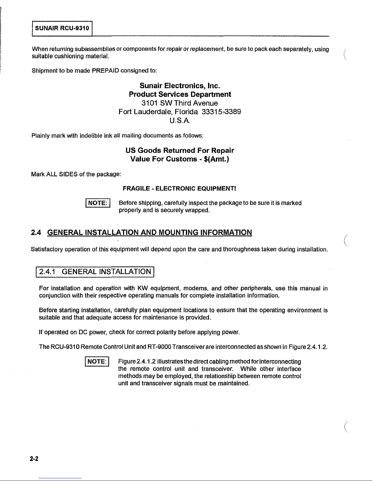
When returning subassemblies or components for repair
suitable cushioning
Shipment
to
be
material. (
made PREPAID consigned to:
or
replacement, be sure to pack each separately, using
Sunair Electronics, Inc.
Product Services Department
3101
SW
Third Avenue
Fort Lauderdale, Florida 33315-3389
U.S.A
Plainly mark with indelible ink all mailing documents as follows:
US Goods Returned For Repair
Mark ALL SIDES
of
the package:
I NOTE: I
Value For
FRAGILE - ELECTRONIC EQUIPMENT!
Before shipping, carefully inspect the package
properly and is securely wrapped.
Customs-
$(Amt.)
to
be
sure it is marked
2.4 GENERAL INSTALLATION AND MOUNTING INFORMATION
Satisfactory operation
of
this equipment will depend upon the care and thoroughness taken during installation.
12.4.1 GENERAL INSTALLATION I
For
installation and operation with
conjunction with their respective operating manuals
Before starting installation, carefully
suitable and that adequate access for maintenance is provided.
If
operated
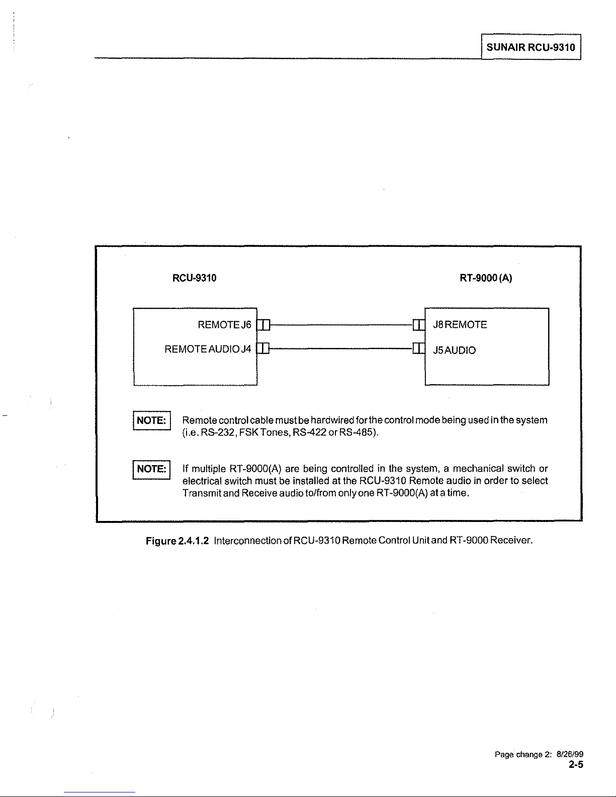
RCU-931 0 Remote Control Unit and RT-9000 Transceiver are interconnected as shown in Figure 2.4.1.2.
The
on
DC power, check
I NOTE: I
Figure 2.4.1.2 illustrates the direct cabling method for interconnecting
the remote
methods may
unit and transceiver signals must be maintained.
KW
equipment, modems, and other peripherals, use this manual in
for
complete installation information.
plan equipment locations to ensure that the operating environment is
for
correct polarity before applying power.
control unit and transceiver. While other interface
be
employed, the relationship between remote control
(
2-2
(
I SUNAIR RCU-9310 I
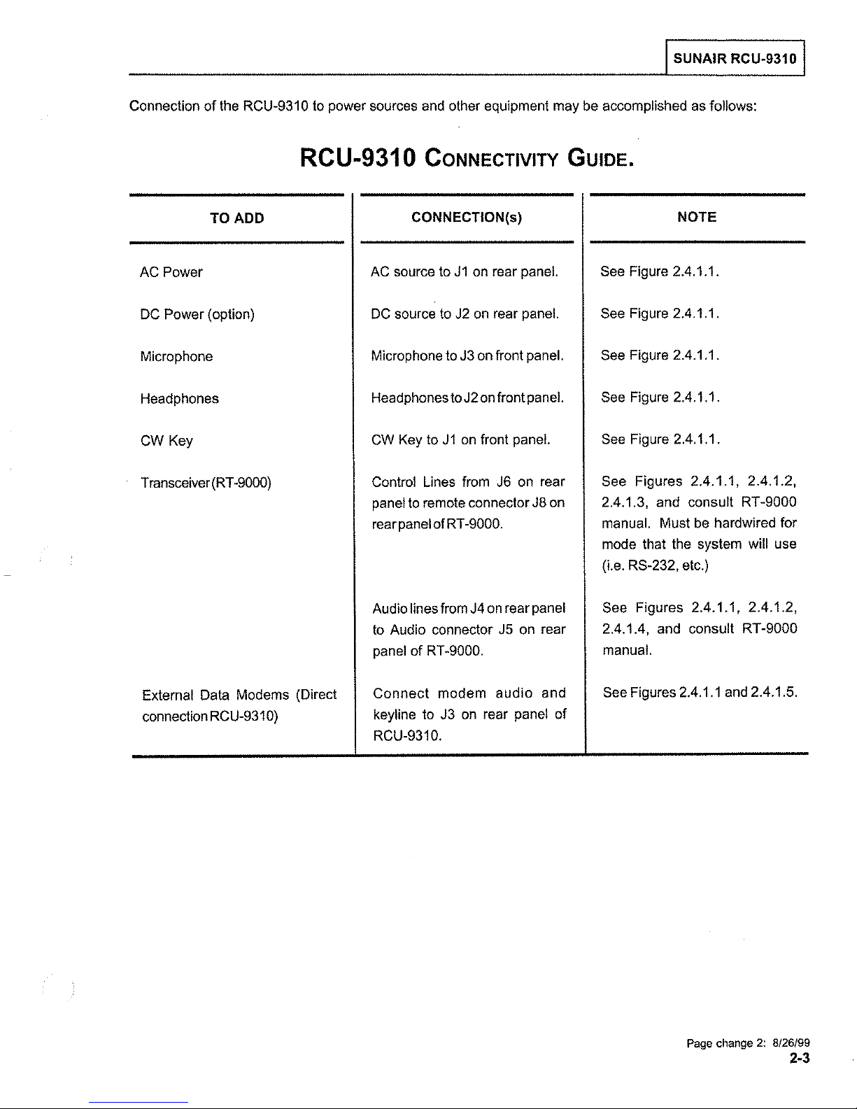
Connection
AC Power
DC Power
Microphone
Headphones
CW Key
Transceiver (RT
of
the RCU-931 0 to power sources and other equipment may be accomplished as follows:
TO
ADD
(option)
-9000)
RCU-9310
AC
DC
Microphone to J3 on front panel.
Headphones
CW Key to J 1
Control Lines from J6 on rear
panel
rear panel of
CONNECTIVITY GUIDE.
CONNECTION(s)
source to
source
to
J1
on rear panel.
to
J2
on
rear panel.
to
J2
on
front panel.
on
front panel.
remote connector J8 on
RT-9000.
NOTE
See Figure 2.4.1.1.
See Figure 2.4.1.1.
See Figure 2.4.1.1.
See Figure 2.4.1.1.
See Figure 2.4.1.1.
See Figures 2.4.1.1, 2.4.1.2,
2.4.1.3, and consult
manual. Must be hardwired for
mode that the system will use
(i.e. RS-232, etc.)
RT-9000
External Data Modems (Direct
connection RCU-931
0)
Audio lines from J4 on rear panel
to Audio connector J5 on rear
panel
of
RT-9000.
Connect
keyline to J3
RCU-9310.
modem
on
audio
rear panel
and
of
See Figures 2.4.1.1, 2.4.1.2,
2.4.1.4, and consult RT
manual.
See Figures 2.4.1.1 and 2.4.1.5.
-9000
Page change
2:
8/26/99
2-3
I SUNAIR RCU-9310 I
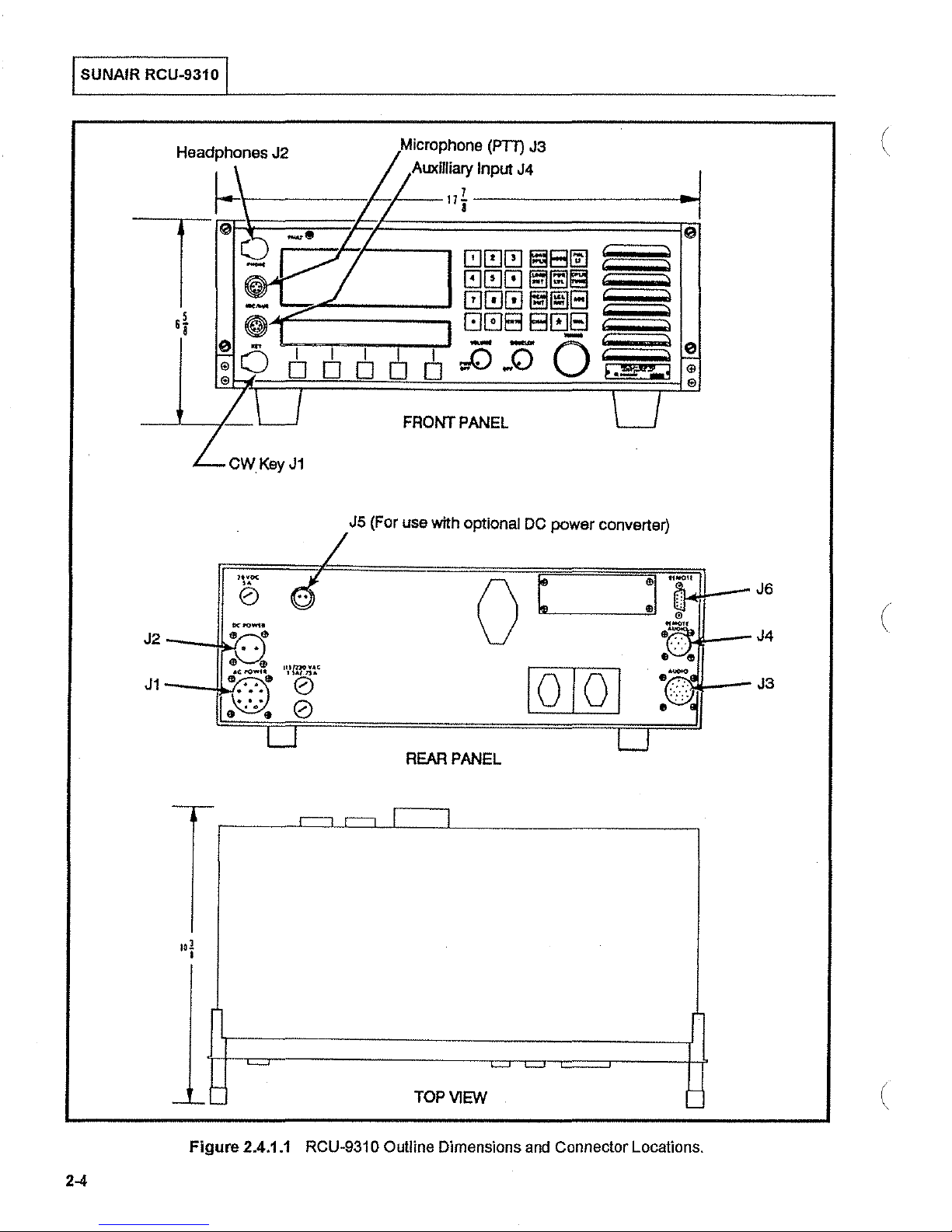
Headphones J2
r-------/--/---111-----------l-~·
CWKeyJ1
1h'OC
6
I I I I
DODO
J5 (For use with optional
Microphone
Auxllliary Input J4
(PTT)
I
Ol
FRONT PANEL
J3
DC
power converter)
..
(
,
(
2-4
-'-'-
Figure
REAR PANEL
.r----1
-
2.4.1.1 RCU-9310 Outline Dimensions and Connector Locations.
,.....,
I
TOP
I
VIEW
-
(
I
SUNAIR
RCU-9310 I
RCU-9310
REMOTEJ6
REMOTE
AUDIO
J4
n
n
I NOTE: I Remote control cable must
RS-232,
(i.e.
If multiple RT-9000(A)
electrical switch must
Transmit
Figure 2.4.1.2 Interconnection of
FSK
Tones, RS-422 or RS-485).
are
be
and
Receive audio to/from only
be
hardwired for
being controlled
installed at
RCU-931 0 Remote
the
RCU-931 0 Remote
one
-IT
-IT
the
control
in
RT
Control Unit
mode
the
system, a mechanical switch or
-9000(A) at a time.
RT-9000(A)
J8REMOTE
J5AUDIO
being
used
audio
in
and
RT
-9000 Receiver.
in
the
system
order to select
Page change 2: 8/26/99
2-5

I SUNAIR RCU-9310 I
822981
(
ACU-93!0
8
PIN
CONNECTOR
DB-9
FEMALE
)-~X~M~T--------------~R~S~-=2~3=2
_!R~C~V~------------~A~S~-=2~3=2--------------------~XM~T~
2 1
>
5 5
AS-232
)-----------------~F~S~K_T~O~N~E~----------------------<2
________________
>
2
XMT
XMT
RCV
ACV
RS-422
HIGH
LOW
HIGH
LOW
6
7
8
9
CONTROL INTERCONNECT 150
_!F~S~K_T~O~N~E~----------------------<
TONE
MODEM
CONTROL
CONTROL
INTERCONNECT
_____________________
GROUND
INTERCONNECT
-
AS
422
RS-422
AS-422
RS-422
RCV
RCV
XMT
XMT
\4000
FT.
FT.
HIGH
LOW
HIGH
LOW
MAX.)
MAX.!
AT-9000
15
PIN
DB-15
9
PIN
DB-9
R~C~v~
!AJ
CONNECTOR
FEMALE
OR
CONNECTOR
FEMALE
2
8
9
6
7
8
1----<
9
6
MULTIPLE
RT-9000
7
B
,~----<
9
'
6
'
7
!AI
(
----------------~R~S~-4~8~5~H~l~GH~--------------~----~
'>
8 8
9 9
Page change
2:
AS-485
8/26/99
Figure
CONTROL
2.4.1.3 FSK, RS232, RS-422,
2-6
AS-485
INTERCONNECT
LOW
\4000
FT.
MAX.!
H--<8
f-< 9
Hi--<
~9
or
RS485 Wiring Diagrams.
MULTIPLE
RT-9000
8
IAJ
(

RCU-9310
10
PIN
P/N
1010650025
l
PW06A-12-
CONNECTOR
lOP)
A>--
-------'T_:.:Rc::_ANSMJ
T
AUD,_,l_:=O
__
I SUNAIR RCU-9310 I
RT
-9000
PIN
(A)
CONNECTOR
19
P/NJQ1 1 l40004
(PW06A-14-l9P)
REMOTE
AUO!O
c
>-----
E )
F >
G)
H)
J >
----·
TRANSMl
T _
_::AcoU::_D.cl
Dc:_·c_
__
_
AUDIO
JS
Figure 2.4.1.4 RCU-9310 Remote Audio to RT-9000
(A)
Audio Wiring Diagram.
2-7
~
::!!
co
c:
til
~
-
"'
~
c
12
-
0
~
5"
5
~
3
!!!.
~
;::
g_
~
"'
§;
:::!.
::>
co
0
&"
ii)
?
MATES
WITH
RCU-9310
REAR
CONNECTQF'i
'"AUDIO""
/----,_
19
PlN
CONNECTOR
PN_
1011140004
[PI'/OSF-14-!SP)
'"
CABLE,
!9
CONDUCTOR.
U24
PN
!011200015
BUSHING. TELESCOPING
PN
0700550046
a·
-
~
~
~
m
VIHT
/V
IO
1'/HT/BLU
\'IHT/GRN
v.HT/YE!...
\\IHT/ORN
WHT
/REO
WHT/SAF-.:
I'IHT
/BLK
~'
GR'
'<0
1'/HT/GAY
BAN
acu
GRN
m
ORN
RGO
ee<
~
en
c:
~
Si
:II
0
c:
;
0
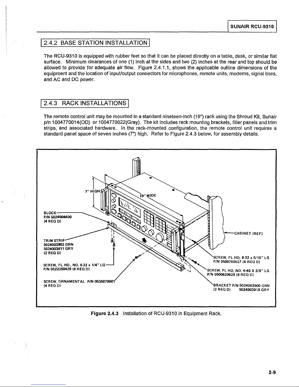
12.4.2 BASE STATION INSTALLATION I
I SUNAIR RCU-9310 I
The RCU-931 o is equipped with rubber feet
surface. Minimum clearances
allowed to provide for adequate
equipment and the location
and
AC and DC power.
of
one (1) inch at the sides and two (2) inches at the rear and top should be
air
flow. Figure 2.4.1.1, shows the applicable outline dimensions
of
input/output connectors
12.4.3 RACK INSTALLATIONS I
The remote control unit may
p/n 1 004
strips, and associated hardware.
standard panel space
770014(00)
be
mounted
or
1004 770022(Gray). The kit includes rack mounting brackets, filler panels and trim
In
the rack-mounted configuration, the remote control unit requires a
of
seven inches (7") high. Refer to Figure 2.4.3 below,
so
that it can be placed directly
for
microphones, remote units, modems, signal lines,
in
a standard nineteen-inch (19") rack using the Shroud Kit, Sunair
on
a table, desk,
for
assembly details .
or
similar flat
of
•
the
5024003811 GRY
12REQD)
PIN
0522350429
SCREW.
(4 REOD)
ORNAMENTAL PiN 0538870001
(8
REO
D)
Figure
,.
.!\
2.4.3 Installation
~
0
of
RCU-931 0
in
Equipment Rack.
)
CABINET (REF)
BRACKET P/N
(2
REO
D)
5024003900
5024003918 GRV
GRN
2-9
I SUNAIR RCU-9310 I
(
ITHIS PAGE INTENTIONALLy LEFT
BLANK.!
(
2-10
(
(
RCU-93108
Remote Control Unit
(
\
Please refer to Section
manual for RCU-931
OB
VI
Supplement of this
Operating Instructions.

/
\
(
(

I SUNAIR RCU-9310 I
SECTION IV
THEORY OF OPERATION
4.1 REMOTE CONTROL UNIT-TRANSCEIVER INTERFACE AND INTERACTION
The RCU-931 0 Remote Control Unit and its companion RT-9000 Transceiver interconnect and communicate
means
--provide
110
Receive audio input and transmit audio output are applied, respectively, to the remote unit from the transceiver
and to the transceiver from the remote unit over separate pairs
Transmit Audio Output connections are provided by the 'Remote Audio' connector (J4) on the remote control unit's
rear
From an operational standpoint, the RCU-931 o can
duplicates the primary operator functions
the transceiver, the transceiver's primary operator controls are inoperative. The reverse is true when the
transceiver has
Both the RCU-931 0 and the RT-9000 are software-controlled, microprocessor-based units, using similar devices
and technology. The remote unit's software provides the control and interface capability forthe front
processes incoming and outgoing messages, and
transceiver.
of
two
110
ports and two sets
the communications path
port connections are provided by the 'Remote' connector (J6) on the remote control unit's rear panel.
panel.
control.
of
audio lines. The
for
all operational,
a)
channel number and frequency information
b)
mode selection and tuning commands
c) transmit and receive commands
d) automatic scan and ALE setup and activation
e)
operator messages
of
the RT-9000 Transceiver. When the RCU-931 0 assumes control
110
or
be
--when
ports-- one each on the remote unit and transceiver
control, data:
of
audio lines. The Receive Audio Input and the
viewed as a remote control panel that essentially
in control -- generates functional commands to the
panel display,
by
of
4.2 REMOTE CONTROL UNIT
The RCU-931 0 Remote Control Unit contains the circuitry to allow the remote operatorto control all
of
the
RT
functions
The major functional assemblies
follwing paragraphs.
Figure 4.1, the
assemblies; schematic diagrams are included in Section V
-9000 Transceiver.
overall block diagram
of
the RCU-931 0 Remote Control Unit are listed below and described
(1) Front Panel Assembly
(2) CPU Assembly 3A2A 1
(3) Audio/Remote Audio Assembly 3A2A2/3A2A4
110
(4)
(5)
Assembly 3A2A3
AC and DC Power Supplies 3A3A 1/3A3A2
of
the RCU-9310, illustrates the functional relationship between these
3A1
of
this manual.
ofthe
primary
in
the
4-1

SUNAIR RCU-9310
AEMI
'"
PANEl
~EMCHE
AUOIO
H
XMtr
A~~--~-,,
3A:lA~
"
REMOTE
ASSEMSL
AUDIO
Y
3A2A2 AUDIO ASSY.
501,0il(H
00</llF>
-.~
='~
AOJI'.UD
""
SGUHCH
((ltol>b);
PC~R
f'OJ!iR
0!<1(1f
Sll'l'l1
I~
;uoiO <<l
IHIOOfiO
REMIP•>*L
AU>:
<<lIN
~~~>.<!Ill
~
..
•UI)IO
(
3A1
FRONT
PANEL
ASSY
MICROPROCESSOR
3A3
POWER
SUPPLY
ASSEMBLY
ASSEMBLY
3A:.!Al
t--++-
.---1-+-
L_------~====~
::'
":']
~·
A$l!!ol!O.r
•26
voc
(
Figure
4.1
4·2
(
RCU-9310 Remote Control Unit Block Diagram.

I SUNAIR RCU-9310 I
14.2.1 FRONT PANEL ASSEMBLY
The front
appropriate subassemblies.
the microprocessor assembly
indicates
power
display
transmit/receive
Built-In
the transceiver's
messages
unit
Selecting the
unit's microprocessor
If a fault
a
message
will activate the test routines
monitor
A 'soft-key'
functions,
Day,
speaker control.
panel
assembly contains the circuitry necessary
(Transceiver)
level,
and
which
can
Test
Equipment
are
displayed
or
the transceiver.
'Local
is
detected,
on
the
the
testing the transceiver's
menu
such
as
etc.
The
soft
It also provides
with
the
various other assemblies. A
operating status
local/remote control
selectively indicate receive
audio
levels.
(BITE)
BITE
can
BITE' function exercises a comprehensive test
software)
the 'FAULT' Light Emitting
LCD
will indicate
LCD
located directly below the primary display permits
Scan,
keys
monitors the status ofthe remote control unit's plug-in assemblies.
be
activated
on
the
LCD,
that
in
the transceiver's microprocessor software
Sounding,
also
provide access
such
as
selected
and
providing assurance ofthe continuing functionality of
checks
which
LRU
LRU's.
Automatic
3A11
to
provide
and
accepts digital information through the control/data bus
as
frequency, channel,
by
a front panel
signal
strength, transmit forward/reflected
monitored
all
plug-in
to
from
the
remote
subassemblies
Diode
(LED)
in
is
inoperative. Similarly, selecting the 'Remote BITE' function
Link
Establishment
meter selection, 1/0 port configuration, remote
analog
wide
keypad.
control
routine
to
the
upper left corner of the
(ALE),
and
screen
mode,
The
unitfront
(contained
the
the Lowest
and
the
Local
Liquid Crystal
BFO,
the
selection of
and
control interfacing
Display
AGC
release
LCD
contains a
power,
panel.
in
Repairable
remote
Remote
and
Plain
the
remote
the remote control
panel
control unit
several
BITE,
with
(LCD)
time,
bar
graph
600-ohm
In
addition,
language
control
Unit
(LRU).
will light
LCD
enhanced
Time-of-
audio,
the
via
RF
and
will
and
14.2.2 CPU ASSEMBLY 3A2A
4.2.2.1 GENERAL
The
CPU
Assembly
status indications
of transceiver operations, the microprocessor
transceiver.
software
Communications
provided
4.2.2.2 MICROPROCESSOR U2
The 8-bit
instructions
on
4.2.2.3 ERASABLE PROGRAMMABLE READ-ONLY MEMORY (EPROM)
The
the
routines
by
80C85
the
CPU
EPROM'S,
RCU-931
the control/data
(software)
Assembly
provides overall control of
and
executes the
These
0 functions.
commands
and
perform
between
microprocessor,
U13
and
the
stored
by
means of a multiplexed address/data
U14,
bus.
in
stores the program(s) or software executed
11
RCU-931
RCU-931
are
decoded
the designated function(s).
Microprocessor Assembly
U2,
EPROM'S
is
O's
the
U13
internal
provides
by
primary
and
0 functions. It
BITE
message control
the transceiver
control for all
U14.
U2
enables
routines.
and
controls
When
to
execute the appropriate (transceiver)
the other major functional assemblies
RCU-931
and
communicates
bus.
by
most Front
the
RCU-931 0 assumes
and
generates
0 functions. It executes the
U13
the microprocessor U2to control
with
AND
Panel
controls
control
commands
the other circuits
U14
to
and
the
are
4-3

I SUNAIR RCU-9310 I
4.2.2.4 ELECTRICALLY
Long term storage of the RCU-9310 ALE functions is handled by the non-volatile memory in
BK
X 8 bit CMOS EEPROM in which each byte may be reliably written 10,000 times without degrading device
The
operation.
applied.
4.2.2.5 STATIC RANDOM ACCESS MEMORY (SRAM) U3
The SRAM provides temporary storage that is used as a "scratch pad" by microprocessor U2 during the
execution of its program with U13 and U14.
4.2.2.6
Watch is
Smart
seconds, seconds, minutes, hours, days of the week, days
lithium energy cell maintains time information when the equipment is turned off. The above information is
available to microprocessor U2 for selective display on the Front Panel LCD as time-of-day clock.
data in the byte will remain valid after its last write operation for ten years with or without power
OPTIONAL SMART WATCH U14(A)
an
optional device that is "piggy-backed" into socket U14. It keeps track of: hundreths of
I NOTE: I
ERASABLE
The Smart Watch in the remote control unit is completely independent
of
the Smart Watch in the transceiver.
PROGRAMMABLE READ ONLY MEMORY (EEPROM)
of
the month, months, and years. An embedded
US.
US
US
is an
(
14.2.3 OPTOCOUPLER ASSEMBLY 3A2A 1 A
The Optocoupler, a subassembly that plugs onto
Optocoupler electronically isolates the CPU's multiplexed address/data bus from the control/data bus
prevent noise transfer to/from the microprocessor (U2).
the
11
CPU Assembly, contains optically-coupled isolators. The
14.2.4 AUDIO/REMOTE AUDIO ASSEMBLIES 3A2A2/3A2A4I
The Audio/Remote Audio Assemblies process the Remote Receive Audio input signal from the transceiver
the
to drive
modems.
Audio inputfrom a microphone,
Assemblies
over the transmit audio
After converting the receive 600 ohm audio to single ended output in the Remote Audio Assembly, the
Receive Audio
to the connected
3.3.9).
bypassed-switched to the Syllabic Squelch and Electronic Volume Control circuits. The output of the
Electronic Volume Control is amplified and switched (controlled by a designed-in Mute function
ON/OFF)
for headphone audio. Full power audio is routed through an energized relay
front panel speaker, headphones, and to provide two selectable 600-ohm audio outputs to external
CW
key, or selected external device is processed by the Audio/Remote Audio
to
produce an amplified 600 ohm Transmit Audio output signal that is applied
lines.
signal is amplified and routed
external device ('A'
The
amplified input signal can be electronically switched through a
and routed to
the
Speaker Driver.
or
to
the 600-ohm line drivers to provide a balanced 600-ohm output
'B',
as
determined by the
The
output is dropped through
'Une
Audio' selection described in Section
CW
Narrowband Audio Filter
R111
and routed to
(K3)
to the front panel speaker.
to
the transceiver
or
Squelch
the
front panel
(
to
or
I NOTE: I
4-4
When headphones are
de-energized,
plugged into the front panel, relay K3 is
disabling the audio to
the
speaker.
(

The
Squelch
received
and --if it
Driver.
poises
The Syllabic
or
circuit is a true syllabic type that operates
audio,
has
short
such
as
noise,
voice
characteristics-- turns
Squelch
fades,
I
NOTE:
minimizing
I
data,
etc.
The
on
circuit
is
designed
the effects of nuisance interruptions.
This
is
a function
transceiver into
squelch
Receive
the
Receive
to
remain
in
the
on
voice
Audio input
Audio
inactive
RCU-9310
operation.
characteristics
is
sampled
switch
(i.e.,
and
and
audio
does
passes
I
SUNAIR
and
rejects other types
in the Syllabic
through
unsquelched)
not
put
the
remote
RCU-9310 I
of
Squelch
to the Speaker
during
circuit
voice
During
The
electronically
controlled
or
and
Transceiver.
The
buffered
can
ohm
Keying
Audio Amplifier. A
Transmit
microphone
by
switched
applied
600-ohm
and
also
be
audio
the
operation,
input
switched
an
internal
to
bypass
to
a line driver
balanced
electronically
internally
signal
CW
then
key
them.
switched
enables
second
input
signal
from
to
the
Microphone/600-ohm
adjustment.
The
microphone
on
the
audio
from
switched
to
follows the
the
CW
buffer
to
the Audio Assembly originates
the front
Remote
external
through the Microphone/600-ohmAudio
pass
same
Sidetone
and
14.2.5 1/0 ASSEMBLY 3A2A3I
a)
Microphone,
b)
600-ohm
c)
CW
The
output
Audio
through, or
path
internal level control
balanced
key.
panel
is
routed
Audio
may
be
audio
is
then
Assembly
input
level
bypass,
as
the microphone
Switch.
lines,
to
the
Switch
fed
through
amplified,
to
provide a
is
controlled
the Transmit
The
CW
provides
from
or
Audio
circuits. This
the Transmit
switched
600-ohm
by
an
Audio
signal.
tone
is
buffered
sidetone
one
of three
Assembly
microphone
Audio
to
the
Transmit Audio
internal
Switch
Compressor
and
to
sources:
where
Transmit
adjustment.
circuits.
the
it
is
Compressor
Audio
This
circuits.
coupled
Speaker
amplified
output
signal
This
audio signal
to the Transmit
Driver.
and
level
is
circuits,
Amplifier,
to
the
signal
is
The
600-
The
1/0
Assembly
is
dedicated
remote
or
1/0
(U9)
special instructions
commands
The organization of the
simultaneously.
control
RS-485
Port
functions
under
formats
to
be
used
unit
control
from
contains
for
and
its
at
speeds
I
NOTE:
are
implemented
ofthe 1/0 Assembly's microprocessor
(software
the
Front
two
independent
future
specific
companion
of
300,
Port A may
I
FSK
Line
contained
Panel
or Microprocessor Assembly.
1/0
Assembly
1/0
ports,
predetermined
transceiver.
600,
1200,
be
used
Tone
Modem
Select
by a
(3A2A6)
Dual
in
EPROM
hardware
designated
operations.
This
port
is
configurable
2400,
4800,
9600,
for communications
(3A2A3A1)
and
Phone
Universal
Asynchronous Receiver/Transmitter
(U1
U20)
in
and
software
'A:
and
'B'.
Port A provides
from
19200
baud
over
and
optional
Interface
0).
The 1/0
response
is
such
Port B is
the
control
or
FSK
telephone
PC
(3A3A4).
Assembly
to
messages
that
an
RS-232,
the
control
Assemblies
interface
panel
tones
at
lines
mic,roprocessor
from
both
ports
9600-baud
for
RS-232,
300
with
Phone
(DUART)
the transceiver or
can
between
baud
the
be
port
that
RS-422,
only.
circuit
executes
active
the
4-5

I SUNAIR RCU-9310 I
14.2.6 POWER SUPPLY ASSEMBLIES 3A3, 3A3A
The
RCU-931 0 operates
are
connected,
source.
source.
The
3A3A
before
to
regulated output for
When
AC
power
1.
This
being
produce
The
the+
the
supply
AC
supply
+28
VDC
routed
12
from
RCU-9310
will
sense
line
returns,
assembly
is
routed
to
the
circuitry
VDC
regulated
the
RCU-931
either a
operates
AC
line
the
unit
(3A3)
produces
to
PC
in
the
output
0 circuitry.
+26
VDC
from
the
reductions
will
automatically
assembly
RCU-9310.
routed
to
or
120/220
AC
line
input,
or failure
switch
unregulated
3A3A2
RCU-931
The
where
+28
VAC
and
DC
0 circuitry
1,
and 3A3A21
power
using
the
automatically
back
to
AC
that
is
regulated
the
+28
VDC
is
also
and
source.
+26
VDC
line
VDC
is
sentthru
to
3A3A2
When
input
switch
power.
to
+28
fuse
R1
U2
both
power
as a backup
to
the
backup
VDC
in
(3A3A2
and
producing
F1)
R2
PC
assembly
protected
to
3A3A2
the
sources
power
voltage
U1
+5
VDC
(
(
(
I SUNAIR RCU-9310 I
SECTION V
FAULT ISOLATION/MAINTENANCE AND REPAIR
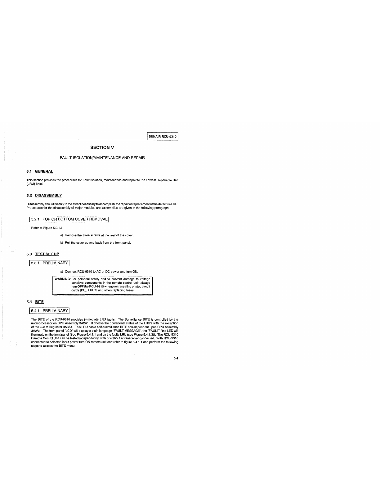
5.1
GENERAL
This
section provides the procedures for Fault Isolation, maintenance and repair
to
the
Lowest Repairable Unit
(LRU)
level.
5.2
DISASSEMBLY
Disassembly should be only to the extent necessary to accomplish the repair or replacement
of
the defective LRU.
Procedures for the disassembly
of
major modules and assemblies are given in the following paragraph.
15.2.1 TOP OR BOTTOM COVER REMOVAL I
Refer to Figure 5.2.1.1
a)
Remove the three screws
at
the rear
of
the cover.
b)
Pull the cover up and back from the front panel.
5.3
TEST SET UP
js.3.1
PRELIMINARY!
5.4
§Jig
a)
Connect RCU-931 0
to
AC or DC power and turn ON.
WARNING: For personal safety and to prevent damage to voltage
sensitive components in the remote control unit, always
turn OFF the RCU-931 o whenever resealing printed circuit
cards
(PC), LRU'S and when replacing fuses.
ls.4.1
PRELIMINARY I
The
BITE
of
the RCU-931 0 provides immediate LRU faults. The Surveillance BITE is controlled by the
microprocessor on
CPU Assembly 3A2A 1. It checks the operational status
of
the LRU's with the exception
of
the +28 V Regulator 3A3A 1. This LRU has a self-surveillance BITE non-dependent upon CPU Assembly
3A2A1. The front panel "LCD" will display a plain language "FAULT MESSAGE", the "FAULT" Red LED will
illuminate
on the front panel (See Figure 5.4.1.1 and on the faulty LRU (see Figure 5.4.1.3)).
The
RCU-9310
Remote Control Unit can be tested independently, with or without a transceiver connected. With RCU-931 0
connected to selected input power turn ON remote unit and refer to figure 5.4.1.1 and perform the following
steps
to
access the BITE menu.
5-1

I SUNAIR RCU-9310 I
5-2
'l
..
I
(
TOP
COVER
(
(
Figure 5.2.1.1 Top/Bottom and Card Cage Covers Removal.

0
~
®
®
I SUNAIR RCU-9310 I
4 5
I
-~
0
0
FAULT
RCV 9.16717
MHZ
CH
26
QJ00
~
J•oofjl
PNLI
LT
PHONE
S3
S6
S9
+20 +40 +60
000
~
METER········
[;B
I
PWR
IICPLRI
LVL
TUNE
,_
:\'~SEL
REMOTE OR
LOCAL
000
~~EJ
MIC/AUX
'"'
~
BFCl-
BITE
MCH-
ALE-10 MORE
008
jcHANJI
ALE
JJ
MIL
j
VOLUME
SQUELCH
TUNING
KEY
0
~
0
I
cb
I I
cb
PWRO
OFP
I I
0
0
0
OFF
RCU-9310
®
®
2
3
1
Figure
5.4.1.1 RCU-931 0 Feature Menu, BITE Selection.
Depress the 'MORE' key 1 successively until the feature menu 2 shown
in
Figure 5.4.1.2 appears.
Depress the
'BITE' key 3 . The message:
'SEL REMOTE
OR
LOCAL'
will appear on the status display screen 4 , and the BITE submenu shown
in
Figure 5.4.1.2 will
be
displayed
on the 'Feature' screen.
II
REM·BITE
LOCBITE
END
II
I
I I I
I
~
D
~
D
~
2
1 3
Figure
5.4.1.2 RCU-9310 BITE Submenu.
Depress the 'LOC BITE' key 1 . The RCU-931 0 will initiate a self-test routine and will display messages
and/or
results on the status screen. The initial message will
be:
'BITE IN PROGRESS'
As each modules tested, a corresponding message will appear briefly on the screen in the following order.
'FRONT PANEL O.K.'
'CPU O.K.'
'POWER SUPPLY O.K.'
5·3

I SUNAIR RCU-9310 I
'1/0
O.K.'
1000
Hz
Audio Tone heard in speaker at this point.
'AUDIO O.K.'
If
any
of
the modules (LRUs) are faulty, the BITE program will halt, the front panel 'FAULT' indicator 5 will
light,
and the status screen will display a message indicating the faulty module:
!s.4.2
COMMON
MODULES I
'FRONT PANEL FAULT'
'CPU FAULT'
'POWER SUPPLY FAULT'
'1/0
FAULT'
'AUDIO FAULT'
!NOTE: I
Refer to Figures 5.2.1.1, 5.4.2.1 and 5.4.2.2 for module cover removal
and
assembly locations.
5.4.2.1 FRONT PANEL FAULT
This is an indication
of
a failure on the Front Panel PC Board Assembly
3A
1 A
1.
a)
Turn RCU-9310
OFF
and remove Front Panel Module 3A1. See Figure 5.4.2.2 on the following page.
b)
Remove and replace Front Panel PC Board Assembly 3A1A1. See Figure 5.4.2.2.
c)
Reinstall Front Panel Module 3A1. Turn RCU-9310 ON.
d)
Repeat "BITE TEST''. Upon completion
of
successful test, return RCU-931 0 to operational status and
return
failed
3A
1 A 1 PC
to
factory for repair.
e)
If
in
step d) above, test fails the Front Panel test again, turn
OFF
RCU-9310 and remove
3A1
Module;
replace
with original
3A1
A 1 PC Assembly. Return the failed
3A
1 Module to factory for repair.
5.4.2.2
CPU
FAULT
This is an indication
of
a failure on the PC Assembly CPU 3A2A1. Check position of DIP Switch S1. (See
Figures 5.8.4 and 5.7.3.1).
a)
Turn the RCU-9310 OFF and remove and replace PC Assembly 3A2A1. See Figures 5.4.2.1 thru 5.4.2.4.
b)
Turn ON RCU-9310 and repeat "BITE TEST". Upon completion of a successful test, return RCU-9310
to
operational status.
c)
Return failed PC Assembly 3A2A 1 to factory for repair.
(
(
(

I SUNAIR RCU-9310 I
5.4.2.3 1/0 FAULT
This is an indication of a failure on PC Assembly
1/0
3A2A3.
a) Turn the
RCU-931 0 OFF and remove and replace PC Assembly 3A2A3. See Figures 5.4.2.1 thru 5.4.2.4.
b) Turn
ON RCU-9310 and repeat "BITE
TEST'.
Upon completion of a successful test return RCU-9310 to
operational status.
c)
Return failed PC Assembly 3A2A3 to factory for repair.
5.4.2.4 AUDIO FAULT
This is an indication of a failure on the Audio PC Board Assembly 3A2A2. Check DIP Switch S1. See Figure
5.8.6.
a) Turn RCU-9310 OFF and remove and replace 3A2A2. See Figure 5.4.2.1.
b)
Turn RCU-931 0 ON. Repeat "BITE
TEST'.
Upon completion of successful test, return RCU-931 0 to
operational status. Return failed 3A2A2
to
factory for repair.
OVER
VOLTAGE
(RED
LED)
\
UNDER
VOLTAGE
(RED
LED)
READY
(GR\
LED)
I I
/OVER
CURRENT
(RED
LED)
I
0
'\
/~
/
0
I
""
.
•
•u•~
(
)
1(
~
'if
!?
NOT
USED
110110Nf
()t
19
"
KV
""''
OSC
Uf'lol
"""'"'
'"""'
•v:o
(B
®
I
I
IUC
UNI
OUKIO«
.,,.,.,
•
•
•••••
•
•
I
'IM:Jif.•f(,.~~
I
llMOTE
AUDIO
"
""'
FAUU
""'0
c•u
•
llil
MU~
110
®
~~·:-;
Or-t
Jill
111
.,;;:iL
'--'
'--'
'-
~
!-
..._
FAULT
LED
(RED
LED)
FRONT
PANEL
FAULT
(RED
LED)
NOT
SHOWN
Figure 5.4.1.3 Top View RCU-9310 LRU "Fault Indicators".
5-5

I SUNAIR RCU-9310 I
5.4.2.5 POWER SUPPLY FAULT
This indicates a failure of the +28VDC out of PC Assembly 3A3A2 usually 3A3A2-F1.
a)
Turn OFF RCU-931 0 and check 3A3A2-F1, replace as required.
b)
If 3A3A2-F1 is not blown, use normal troubleshooting procedures and check the +28VDC lines
on
Mother
Board
assembly 3A2A5-J2 pins 23 and 24. If this is correct, the fault is on the CPU assembly 3A2A 1.
1)
Turn RCU-931 0 Off and remove and replace PC assembly 3A2A
1.
See Figures 5.4.2.1 thru 5.4.2.4.
2)
Turn ON RCU-931 0 and repeat "BITE TEST". Upon completion of a successful test, return RCU-931 0
to operational status.
3) Return
failed PC Assembly 3A2A 1 to factory for repair.
5.5 TROUBLESHOOTING WITH SELF-SURVEILLANCE
BITE
Refer to Figure 5.4.1.3.
ls.s.1
AC POWER SUPPLY I
The Self-Surveillance Bite for the AC power supply consists of the following LED's (See Figure 5.4.1.3)
SYMPTOM(s)
AC PQWER ONLY:
a)
GREEN=
READY (3A3A1-CR8)
b)
RED=
OVER VOLTAGE (3A3A1-CR7)
c)
RED=
UNDER VOLTAGE (3A3A1-CR6)
d)
RED=
OVER CURRENT (3A3A1-CR3)
TROUBLESHOOTING
GUIDE.
POSSIBLE
TROUBLE(s)
CHECKS
& CORRECTIVE
ACTION(s)
UnabletoturnunitON.
NoLED'slit
1.
NoACPower.
on 3A3A1.
1.
Check AC power input and take
appropriate action.
2.
Open AC fuses 3A3F1
or
F2.
5-6
2.
Replace
F1
or
F2. If fuse opens
again
use
normal
troubleshooting procedures, locate and
repair short
in
AC power supply.
(
(
(

I SUNAIR RCU-9310 I
TROUBLESHOOTING
GUIDE
(CoNT
...
)
SYMPTOM(s)
POSSIBLE
TROUBLE(s)
CHECKS
& CORRECTIVE
ACTION(s)
Unable
to
turn unit
ON
and
GREEN
t.
3A3A2-K2 or associated circuitry
t.
Troubleshoot and repair or
READY
LED
on
3A3A t lit. 3A3A2-Q2 or
03
faulty. replace faulty component.
Unable to
turn
unit
ON
and
RED
UNDER
VOLTAGE
LED
on
3A3At
lit.
AC
or
DC POWER:
Unit turns
ON,
unable to turn
ON
Front
Panel
LCD
back lite.
Run
local
BITE.
Unit displays "POWER
SUPPLY FAULT'.
No
audio tone
during audio test and
displays
"AUDIO FAULT"
and
Front
Panel
FAULT
LED
is
lit.
Unit
turns
on,
Front Panel LCD
glows, but no information
is
displayed. Unit has
no
RED
FAULT
LED's
lit.
GREEN READY
LED
on
3A3A t
is
lit.
Unit
turns
on,
Front Panel
LCD
glows,
but
no information is
displayed. Unit has
no
RED
FAULT
LED's
lit.
With
AC
power applied
GREEN READY
LED
ON
3A3A t
is
lit.
With
DC
only READY
LED
will
not be
lit.
DC PQWER ONLY:
Unable to turn unit
on.
t.
3A3At-Qt faulty.
2.
Faulty component(s)
on
3A3A
t.
2. Remove and replace
PC
Assembly 3A3A2.
t.
Replace
Qt.
2.
Troubleshoot
and
replace faulty
components, or remove and
replace
PC
Assembly 3A3A
t.
t.
3A3A2-Ft open.
t.
Replace
Ft,
if fuse opens again
use
normal troubleshooting
procedures,
locate
and
repair
short
on
+28VDC lines
in
unit.
t.
3A3A2-Ut or associated circuitry
t.
Replace
Ut.
faulty.
2.
Troubleshoot
and
replace faulty
components or remove and
replace
PC
Assembly 3A3A2.
t.
3A3A2-U2
or
associated circuitry
t.
Replace
U2.
faulty.
t.
No
DC
power.
2.
3A3A-F3 open.
3.
3A3A2-Kt,
K2
or associated
circuitry
faulty.
2.
Troubleshoot
and
replace faulty
components or remove and
replace 3A3A2.
t.
Check
DC
power input
and
take
appropriate action.
2.
Replace
F3,
if fuse opens again,
use
normal troubleshooting
procedures,
locate and repair
short
in
DC
circuitry.
3.
Troubleshoot
and
replace faulty
component(s) or remove and
replace
PC
Assembly 3A3A2.
5-7

~
::n
CQ
c
iil
"'
~
-
s:
-5·
~
~
(/)
CD
3
CT
-<
b
~
::>
?'
~.
3A2A 1 PC
ASSEMBLY CPU
3A1
FRONTPANELASSEMBLY
~
~~~
3A2A4
PC
ASSEMBLY
REMOTE
AUDIO
BOARD
3A3
REAR
CHASSIS ASSEMBLY
/'.
3A 1 A 1
PC
ASSEMBLY
FRONT
PANEL
31>2/>2
PC
ASSEMBLY AUDIO
~
(/)
c:
~
:s
::0
(')
c:
~
-
0

I SUNAIR RCU-9310 I
3A1
FRONT PANEL ASSEMBLY
3A2A1
PC ASSEMBLY
CPU
3A2M.
PC ASSEMBLY AUDIO
3A2A5
MOTHER
{Bottom
of
Main
Chassis)
•
•
3A3A3
PC
ASSEMBLY AUDIO CONNECTORS
3A3/>2
PC ASSEMBLY 5/12V REGULATORS
3A3A1 PC ASSEMBLY28V REGULATOR
3A3 REAR
CHASSIS ASSEMBLY
Figure 5.4.2.2 Removal of Front and Rear Panel and Major Assemblies Locations.
5-9

j
I
r
I SUNAIR RCU-9310 I
5-10
8078073291
8078072295
U13
U14
Ribbon cable connections
\
'1\:JQ'a~~~
naaa~~
!.""=:!====~
aaaaaa
d---------..
a~~~~\:3.
~
\:'}
'\':')
\.) ~ (j
WARNING
Make
sure
!/0
cable
doesn't catch
on
the black
transformer located on the
Front Panel
as
the
CPU
Assembly
is
removed
and
replaced.
CPU
Assembly 3A2A 1
8076113296
U20
Figure
5.4.2.3 Removal I Replacement of CPU 3A2A1 and 1/0 3A2A3.
(
(
(

3A2A1A1
PC
ASSEMBLY
OPTOCOUPLER
3A2A 1 PC
ASSEMBLY
CPU
TO
FRONT
PANEL
3A1A1
TO
REAR
PANEL
J6
3A2A3
PC
ASSEMBLY
1/0
3A2A3A 1 PC
ASSEMBLY
FSK
/
I SUNAIR RCU-9310 I
/
/
/
Figure
5.4.2.4
Removal/
Replacement
of
110
3A2A3 or FSK 3A2A3A 1.
5·11

SUNAIRRCU-9310
ls.5.2
INSTALLATION OF NEW BACKLIGHTING DEVICES FOR FRONT PANEL LCDs. (
The
Backlighting devices for
the
two
(2)
Front
Panel
LCD's
PiN
8076041791
and
PiN
8076040892 will gradually lose
their luminescence
with
time.
For this
reason
operating personnel
should
turn OFF the panel light when ever it
is
not
needed to give
the
Backlighting devices
the
longest possible life.
This
is
accomplished
by
depressing
the
'PNLL T'
push
button
on
the Front
Panel
to
turn
OFF
the Backlighting
and
depressing it again to turn
the
Back-lighting
ON
again when needed. Once
the
Backlighting devices
have
losttheir luminescence,
the
backlight may
be
renewed by
ordering
replacement Backlighting devices for
the
applicable
LCD
and
installing per Figures
5.5.2.1
through 5.5.2.3.
!NOTE:
I
Page change
2:
8/26/99
5-12
1.
2.
Custom
LCD,
Full
Function,
PiN
8076040604.
Replacement Backlight, Assembly
PiN
8076040892.
Custom
LCD,
1 x
40
Character, Assembly PiN 8076041791.
Replacement Backlight,
PiN
8076041708.
Once
the
Backlights
have
been
replaced
initially, they
can
be
replaced again
as
needed.
When
the
luminescence
has
decreased
remove
the
installed Backlight
and
insert a new
one
in
its
place.
(
(

~
"'
~
c
<D
"'
in
;,
:..
Jl
<1>
i
~
c.
:r
i
~
0
::l
Q.
ir
::l
-
~
!!?..
"U
0
G'
en
<1>
3
0"
~
1. REMOVE RIBBON CABLE CONNECTORS.
2.
REMOVE SIX
(6)
4-40 SCREWS, UFT
PC
BOARD.
3.
REMOVE RIBBON CABLE UNDER P C BOARD.
4.
GO TO FIGURE 5.5.2.2 TO REMOVE
LCD
ASSEMBLY.
5.
INSTAUL
IN
REVERSE ORDER.
8076045096 P C ASSY, FRONT PANEL
1
3
2
'N::i
\,
/ \ I
II
'"""'"
,,
' I \
;(
- !
II
@ @ @
0
P2 MUST MATE WITH
J3
ON LCD ASSY
P1
MUST MATE WITH
J2
ON LCD ASSY
.®
0502560002 FLAT WASHER
#4
0500020001 SPUT LOCK
#4
0500850054 SCREW 4-40 X 5/16
4PLACES
IL_f___ll0
AUGNMENT OF
P1 & J2
CAN BE
SEEN THROUGH THIS OPENING.
WHEN
PROPERLY
ALIGNED,
CONNECTORS
SHOULD
MATE
SMOOTHLY. DO NOT FORCE.
0502560002FLATWASHER
#4
0500020001SPUTLOCK#4
0500850071 SCREW 4-40 X 7/16
CONNECTOR ON KEYBOARD ASSY
UNDER FRONT PANEL BOARD.
CONNECT BEFORE
MOUNTING
FRONT
PANEL BOARD.
en
c
~
::tl
::tl
0
~
.....
0

Y'
-
""'
.,
cCi'
c
~
01
~
1\)
::0
~
~
gJ
c.
5'
~

-;?
"'
"
g.
"'
,g
!',>
~
Y'~
~<0
"'"'
,
<C'
c:
OJ
!"
!"
"'
"'
5"
"'
;;r
/if
g.
::J
0
~
CD
"'
f*
c5
a
cil
0
~.
2
?'
P/N 8076041601 LCD
P/N 8076040604 LCD
NOTE:
DIAGRAM
SHOVIIS
LeD's
SEPARAlED.
KEEP
THE LCD ASSEMBLY INTACT AS SHOWN
IN
FIGURE
5.5.2.2.
1. CUT OFF ORIGINAL BACKLIGHT LEADS AND
DISCARD.
P/N 8076041791 BACKLIGHT ASSEMBLY
.
2.
WITH SILVER
OR
BLACK SIDE TOWARD ORIGINAL
BACKLIGHT, CAREFULLY INSERT
NEW
BACKLIGHT
BETWEEN
GLASS AND OLD BACKLIGHT.
-~~IN
8076040892 BACKLIGHT ASSEMBL'
3. SAME PROCEDURE AS 2.
NOTE: CARE MUST BE TAKEN
NOT
TO BEND
NEW
BACKLIGHT WHILE INSERTING. INSERT
TO
SAME DEPTH
OF
ORIGINAL BACKLIGHT WITH
LIGHT
YELLOW
SIDE TOWARD GLASS OF LCD.
en
c:
z
)>
;ij
~
c:
.0
"'
~
0

I SUNAIR RCU-9310 I
5.6 TEST EQUIPMENT REQUIRED
OR
EQUIVALENT
Multi
meter
Digital Multimeter
Audio Generator
Audio Voltmeter
Frequency Counter
Oscilloscope
100
MHZ
Bandwith
Microphone
CWKey
Card
Extender
600
ohm
1/4
Watt Resistors
Simpson260
Leader LDM-853A
Leader
Model
LAG-1208
Leader
Model
LMV-181A
Systron-Donner
Model6050
Tektronix
465
Sunair
P/N
8076000602
SunairP/N 5024000994
Sunair
P/N
8076003091
WARNING: The adjustments called out
in
the following alignments are
all
that should
be
attempted. Any other adjustments not called
out
are
factory adjustments
and
cannot
be
done
in
the
RCU-
9310. See Figures 5.7.1.1
and
5.7.2.1for test equipment
connections.
5.7 TEST AND ALIGNMENT
/s.
1.1
TRANSMIT REMOTE AUDIO I
(
The
RCU-931
0 transmit audio circuits have
been
factory adjusted to output
OdBm
audio signal
to
the transceiver. (
The
RCU-931 0 is
checked
and
aligned as a
stand
alone unit
by
connecting unit
and
test equipment
as
shown
in Figure 5.7.1.1
and
accomplishing
the
following checks
and
alignments.
Use
Figures 5.7.1.2. and 5.7.1.3
a)
Turn
on
RCU-931
0,
go
to
1/0
menu
and
turn
'OFF'
the
1/0.
Select 'LOCAL', 'MTR-XMT', 'LINE'
and
'LINE AUDIO
A'
and
'MODE
CW'.
b)
On
Audio Board Assembly 3A2A2 set
S1
all
segments
to
'OFF'. Connect
CW
Key
to
front panel
J1
and
key
unit or connect a ground
to
3A2A5 J3
pin
6.
1)
1000Hz audio tone should
be
heard
from
front panel speaker. Measure audio level at 3A2A5
J3
pins E
and
C and adjust 3A2A2
R42
as required for.245 VRMS. With a
600
ohm
resistor across rear panel
J4
pins A and C measure the audio level at 3A2A5 J5 pins 3
and C and
adjust 3A2A4
R1
for OdBm. The
CW tone heard
in
the
speaker may
be
adjusted for loudness with 3A2A2
R29,
as volume control has
no
effect. Unkey unit.
2)
Change mode
to
USB
and connect Audio Oscillator
to
microphone audio J3/J4 pins A
and
D,
adjusted
for
1000 Hz
at
100 millivolts
and
a key switch across pins C
and
A or ground 3A2A5 J4
pin 5 to
key unit.
Measure the audio at 3A2A5
J3
pins E
and C and
adjust3A2A2
R8
for.245 VRMS
and
check the output
at 3A2A5
J5
pins 3
and
C for OdBm. Unkey the unit.
3)
With Audio Oscillator set
to
1000 Hz at OdBm connected
to
rear panel J3 pins Sand J
and a key
switch
across pins G
and
R or ground 3A2A5
J3
pin
20
to
key
the unit. Measure the audio level at 3A2A5 J3
pins E and
C and adjust 3A2A2
R58
as
required for .245 VRMS. Check the output at 3A2A5 J5 pins 3
and
C for OdBm.
Page change 2: 8/26199
5-16
(

I SUNAIR RCU-9310 I
4)
Adjust R
162
as
required
for
bar
meter
on
RCU-931
0 front
panel
to
display
OdBm
±one bar.
(You
will
have
to
have
3A2A2
on
card
extender
P/N
8076003091
to
adjust
R162).
5)
Set3A2A2 S 1 segments 1
and
3 to 'ON'. Measure
the
audio at
3A2A5
J3
pins E and
C and adjust3A2A2
R21
for
.245
VRMS.
Check output
at
3A2A5
J5
pins 3 and C for
OdBm.
6)
Checking
the
output at 3A2A5
J5
pins
3 and C vary
the
Audio Oscillator output from
-1
OdBm
to
+1
OdBm.
The output at
J5
should
remain
constant at
OdBm.
Front
panel
bar
meter should display from
-1
OdBm
to
+1
OdBm
while varying the Audio Oscillator. Unkey
the
unit.
Page change
2:
8/26/99
5-17

I SUNAIR RCU-9310 I
RCU-9310
GROUND
A--
MIOAUDIO
D-
- A 600 ohm resistor and Audio Voltmeter
-[
MIO
REMOTEJ6
PJ
PTTKEY
0-
J3/J4
-C
GROUNDA- _
REMOTE AUDIO
J4
1-n
~
OW
KEY-
pr-
GROUND-
J
KEY
AUDIOJ3
r--.
H XMIT AUDIO B
]-From
- T XMIT AUDIO B
Audio
_ - S XMIT AUDIO A Oscillator
-
J XMIT AUDIO A
- G
KEYSWITCH
'---'"
R GROUND
Interconnection of RCU-9310 Remote Control Unit and Test Equipment.
5-18
Figure 5.7.1.1
RCU-9310 Stand Alone Audio Test Set Up.
0
SlOUONf
fX
$
f.A.UU
esc
r:c_
3A2A2
R58
"/1""
I~',,,~,
',i'A2A2Ra
IX
"'!C
AUDIO
3A2A2
A21
31<2A2
A29
3A2A2
R42
• • •
3A2A2
R119
FAUll
<•u
•
MUll
HO
Figure 5.7.1.2 Top View RCU-9310 Alignment Adjustment Locations.
0
3A2A4
AS
UMOfli
AUDIO
(
(
(

6~-9
g
~
< "
""</
O!pn"rf
ljjed
l!WSUeJ.L
&T
L"S
9Jn6!:1
~
)>t;"U1'l
c->:o
onzo
-
"'
o
r"
§~,
-om
o,:;:-<
~
-
a~
'11
"<
0
·-
~
n
>
"'
.,
5(1'1
El
0
;:;
P
~
1 t
.~
1 ! : 1
i~r
: r
w
>
w
>
w
~1--~-J-----
I
--~-T-
:T
____
ri--r
-----~
---~r
----~-~-,----J-.
--;--
-----i
r~~----u·-
~
--·--------.
n - 1 '"' w
" n = >
. .
~
m m >
;s
-<
tV
~
~
~~ill
~
~
~~
~n
g
I~
@~
__]
"
!
1-----'
f-'---'----®j
"
n>r
oo-
~;!ffi
-
>O
~
[::
m "
- g
>0
~'!!;;;
o
mm
"'
ffi
'
I
@~
f-'----®'
,,~
____________
--
n
_!_
m
---------
------
0~&6-00I:II:II'dNOS
-------
~~~
_:_
L -------
~-
.,~~
"'
c:;::-
2:;
0
~0
L----
n
-----"'
I : I
~~
r-~~-r
r "
~
• 0
~
~~
w
~~
~
••
>
~.;,:..
"
~
~
~
~
~
~
~
N
g
~
f
\
g
''1
------
~-
j
J~-----
>
~
~
0

I SUNAIR RCU-9310 I
15.7.2 RECEIVE
REMOTE
AUDIO
I
The
RCU-931
0 receive audio circuits
have
been factory adjusted to provide
an
OdBm output signal from
an
OdBm
input signal from transceiver.
The
RCU-931
0 is checked
and
aligned
as
a stand alone unit
by
connecting the unit
and
test equipment as shown
in
Figure 5.7.2.1. and accomplishing the following checks
and
alignments. Use Figures 5.7.1.2 and 5.7.2.2.
a)
Turn
on
RCU-931
0,
go
to
1/0
menu and turn 'OFF' the
1/0.
Select 'LOCAL', 'MTR-RCV', 'LINE' and 'LINE
AUDIO A'.
1)
With 1000Hz OdBm input at Remote Audio J4 pins Band
D,
check for OdBm level at 3A2A5
J5
pins
5 and
E.
2)
Measure audio level at 3A2A5 J3 pins Hand J
and
adjust 3A2A4
R8
as
required for a reading of .180
VRMS.
3)
Measure audio
level
at3A2A5J4
pins 1 and
2 and adjust3A2A2 R 119
as
required fora reading ofOdBm
with 600 ohm resistor connected across rear panel J3 pins M and
L.
4)
Bar meter
on
RCU-931
0 front panel should display OdBm ±one bar. Turn 'OFF'
RCU-931
0.
5)
With
DVM
measure resistance between right side of 3A2A2 R 142 and ground. Adjust 3A2A2
R89
for
a 2K
ohm
reading. Turn RCU-9310 'ON'.
(
6)
Turn the Squelch Control fully clockwise, the audio output
of
the RCU-9310 speaker should
be
squelched. Change
the
Audio Oscillator
to
1OkHz
and return to
1OOOHz.
The speaker audio should (
be
active and squelched approximately two (2) seconds after the speaker audio is first heard. This
completes receive remote audio
check
and
alignment. Turn 'OFF'
and
removetestequipmentand return
RCU-931
0 to normal operation.
Page change
2:
8/26/99
5-20
I
NOTE:
I
If problems occur during the check and alignment, remove
and
replace Audio Assembly 3A2A2 or use normal troubleshooting
procedures to check and repair defective circuits. Faulty Audio
Assembly
may
be
sent to Sunair for repairs.
(

I SUNAIR RCU-9310 I
RCU-9310
REMOTEJB
PJ
- B
Audio
Oscillator
-D
REMOTE AUDIO J4
h-.
r-u
AUDIOJ3
h-.
L
.---_A
RCV AUDIO B
]-
To
600
Ohm
- C RCV AUDIO B
Resistor
And
- L RCV AUDIO A
Audio
Voltmeter
..___,
M RCV AUDIO A
Interconnection of
RCU-9310 Remote Control Unit and test equipment.
Figure 5.7.2.1 RCU-9310 Stand Alone Audio Test Set Up.
5-21

SUNAIR RCU-9310
(
'
'
'
'
'
'
(
'
'
'
'
'
'
'
~
J_
__
,
~51:
...
5U:i3
1;1:;~
..1::10:
" u
>o-
-
:.....:?.."'..::....
'
'
'
'
~
'
'
,,
'
'
'
'
'
'
'
.
"
.
"
- >
~
~
-·
""
""
~~
4'
,,
0"
'
'
'
'
'
'
'
'
'
'
~
'
-----
,...
_____
1
~
~
0:
-
0:
-----s-----
-
-----
~-----
e
I
~
I
~
~
,.~:?
-
a:3'i
0
'
"
~
~
00
.
.
"""
-r
...
(
OOZ<t
1-lt<tU<
!LClfu
-
______
,.
___
a.
__
0
. --
N
I -I
~
'
~
rn
~
~
~\l!
w<
••
u
0
..
0
e:E~
"
,,
..
wo
Figure 5. 7 .2.2 Receive Path Audio A.
5-22

I SUNAIR RCU-9310 I
15.7.3
SOFlWARE
SWITCH SETTING CHECKS I
Figure 5.7.3.1 shows the software switch settings on CPU PC Assembly 3A2A1
for
RCU-9310 options.
SOFlWARE
SWITCH SETTINGS ON CPU PC ASSEMBLY 3A2A 1 for RCU-931 0 OPTIONS.
S1
SECTION
1
2
3
4
5
6
7
8
I NOTE: I
S1
Sections 1 through 8 are normally set to OPEN position
(all
rocker switches are raised at open side, see Figure 5.9.4). If while
performing maintenance on the RCU-931 Othe 3A2A 1
is
replaced,
make sure 3A2A 1
S1
is configured for non-optionized or for the
applicable options installed in the remote operated transceiver.
SELECTION
OPTION/FUNCTION
RAISED
AT
RAISED
AT
OPEN NUMBER
OPEN Spare Function I Not used
at
this time.
Spare Function I Not used
at
this time.
OPEN
Normal 1 A2A3A 1 Lincompex not installed
at
remote
operated transceiver.
2
Optional 1 A2A3A 1 Lincompex installed at remote
operated transceiver.
OPEN
Normal ALE/Modem not installed
at
remote
operated transceiver.
3
Optional ALE/Modem installed
at
remote
operated transceiver.
OPEN
Spare
Function I Not used
at
this time.
OPEN
Normal No 1 A2A4 FL5 installed at remote
operated transceiver.
5
Optional 1 A2A4 FL5 installed
at
remote
operated transceiver.
OPEN
Normal F-9800 Preselector/Postselector not installed
at
remote operated transceiver.
6
Optional F-9800 Preselector/Postselector installed
at
remote operated transceiver.
OPEN
Not Connected I Not used
at
this time.
OPEN
Not
Connected I Not used
at
this time.
Figure
5.7.3.1 Switch Settings for 3A2A1 S1.
5-23

I
SUNAIR
RCU-9310
I
(
'THIS PAGE INTENTIONALLY LEFT BLANK.'
(
(
5-24

I SUNAIR RCU-9310 I
5.8 SCHEMATICS AND PARTS LISTS
The following pages contain schematics and parts lists for the RCU-9310, see Figure 5.8 below.
DESIGNATOR
ASSEMBLY
SUBASSEMBLY
DESCRIPTION
3A1
FRONT PANEL ASSEMBLY
3A1A1 PC ASSEMBLY FRONT PANEL
3A1A2 KEYBOARD, 6X4
3A1A3
CUSTOM LCD, FULL FUNCTION
3A1A3A1 EL BACKLIGHT
3A1A4 CUSTOM LCD, 1X40 CHARACTER
3A1A4A1 EL
BACKLIGHT
3A1A5 KEYBOARD,
1XS
3A2
MAIN CHASSIS
P/0
CHASSISASSEMBL Y
3A2A1
PC ASSEMBLY, CPU
3A2A1A1
PC ASSEMBLY, OPTOCOUPLER
3A2A2
PC
ASSEMBLY, AUDIO
3A2A3
PC
ASSEMBLY,
110
BOARD
3A2A3A1
PC
ASSEMBLY, FSK MODEM
3A2A4
PC
ASSEMBLY, REMOTE AUDIO
3A2A5
PC ASSEMBLY, MOTHER BOARD
3A3
REAR CHASSIS P/OCHASSISASSEMBL Y
3A3A1
PCASSEMBL Y,28VREGULATOR5AMP
3A3A2
PC
ASSEMBLY, 5/12V REGULATORS
3A3A3
PC ASSEMBLY, AUDIO CONNECTORS
Figure 5.8 RCU-9310 Assemblies and Subassemblies.
SUNAIR
PART NUMBER
80760400XX
8076045096
8076046807
8076040604
8076040892
8076041601
8076041791
8076046505
80780100XX
8076070091
8076075092
8076090091
8076110092
8076115094
8078085095
8078017090
80780100XX
8078021496
8078025092
8078018096
Page change
2:
8/26/99
5-25

I SUNAIR RCU-9310 I
(
!THIS
PAGE
INTENTIONALLY LEFT BLANK.!
(
(
5-26
I

FINAL TESTED RCU-9310
FINAL TESTED RCU-931 0
3A2A1
PCASSY, CPU
3A2A2
PC
ASSY, AUDIO
3A2A3
PC
ASSY.
1/0
BOARD
3A2A3A1
PC
ASSY. FSK MODEM
3A2A4
PC
ASSY, REMOTE AUDIO BOARD
3A3
CHASSIS ASSY
RCU-9310
3A2A1U13
EPROM W/RCU931 0 SOFTWARE
3A2A1U14
EPROM W/RCU931 0 SOFTWARE
3A2A3U20
EPROM W/1/0 SOFTWARE
BUMPER
13/16 OD 13/16
LG
COVER, CARD CAGE
RCU-9310
COVER, TOP
RCU-9310
COVER, BOTTOM
RCU-9310
CONNECTOR KIT
CONNECTOR KIT
P3
CONNECTOR, POWER, 19 PIN MALE
CABLE
CLAMP, MS3057-8A
P4
CONNECTOR, POWER, 10
PIN
MALE
P6
CONNECTOR, POWER,
DB-9, 9 PINFEM
HOOD, W/SCREW LOCK,
DB-9
80780012)()(
8076070091
8076090091
8076110092
8076115094
8078085095
80780100)()(
8078073291
8078072295
8076113296
0508140005
8078011903
80780123XX
80780125)()(
8078000499
1011140004
1000200001
1010650025
1011960010
1011970015
3A1
3A2
3A2A5
3A3A1
3A3A2
3A3A3
3A3J1
3A3J2
3A3J5
3A3J6
3A3CR1
3A3F1
3A3F2
3A3F3
HSQ1
HSQ1
HSU1
HSU1
HSU2
HSU2
101
IU1
1U2
3A3AQ1
3A3R1
3A3R2
3A3T1
3A3A2U1
3A3A2U2
XF1
XF2
XF3
3A3ZS1
3A3ZS2
CHASSIS ASSEMBLY 3A2/3A3
CHASSIS ASSEMBLY 3A2/3A3
FRONT PANEL ASSY
CHASSIS,
CARD CAGE, REMOTE
PC
ASSY. MOTHER BOARD
PC
ASSY, 28V REGULATOR, 5 AMP
PC
ASSY, 5/12V REGULATORS
PC
ASSY. AUDIO CONNECTORS
CONNECTOR, POWER,
10
PIN, MALE
CONNECTOR, POWER, 2
PIN
ROUND
CONNECTOR, POWER,
2
PIN
ROUND
CONNECTOR, POWER,
9
PIN
MALE
JUNCTION SHELL, DB-9
CABLE,
RIBBON, 9 COND,
28
AWG
DIODE, BRIDGE CBR25-040
FUSE,
MDL, 1.5 AMP, 125V
FUSE,
MDL, 1.5 AMP, 125V
FUSE,
MDQ, 5 AMP, 250V
HEATSINK,
T0-3
TRANSISTOR
HEATSINK, T0-3 TRANSISTOR
HEATSINK, T0-3 TRANSISTOR
HEATSINK, T0-3 TRANSISTOR
HEATSINK, T0-3 TRANSISTOR
HEATSINK, T0-3 TRANSISTOR
INSULATOR,
T0-3
SIL ELASTOMER
INSULATOR,
T0-3
SIL ELASTOMER
INSULATOR,
T0-3
SIL ELASTOMER
TRANSISTOR, PNP,
MJ11031
RESISTOR
5,
5%
20W
RESISTOR
5,
5% 20W
TRANSFORMER,
AC, 200VA
IC.
LINEAR LM350K
IC.
LINEAR l.M350K
FUSEHOLDER, PANEL MOUNT
FUSEHOLDER, PANEL MOUNT
FUSEHOLDER, PANEL MOUNT
VARISTOR, MOV V140LA5
VARISTOR, MOV V140LA5
CAP, PROTECTIVE
.485 DIA.X 3/4
CLAMP, CABLE, FLAT 1 1/16 WIDE
CONNECTOR, RIBBON,
10
PIN FEM
CONNECTOR, HOUSING, 20 PIN
COVER,
REAR PANEL
LH
SIDE PANEL
RH
SIDE PANEL
STANDOFF,
F-F, 4-40 .375 L
PANEL, REAR, REMOTE
I SUNAIR RCU-9310]
80780100)()(
80760400)()(
8078011504
8078017090
8078021496
8078025092
8078018096
1011050005
1010510037
1011230011
1012380025
1011130017
1011150018
1010630024
0896540006
0896540006
0858660008
1005130001
1010710028
1005130001
1010700022
1005130001
1010700022
0841560005
0841560005
0841560005
1010990012
1000080021
1000080021
1010670026
1010600028
1010600028
0849030005
0849030005
0849030005
1011300010
1011300010
1009060015
1008650005
1008070017
1009070011
8078015305
80780103)()(
80780102)()(
1010830023
8078015101
Figure 5.8.1 Final Tested RCU-931
0,
Chassis Assembly 3A3, and Connector Kit.
5-27

I SUNAIR RCU-931 0 I
FRONT
PANEL
ASSEMBLY
3A
1
(
FRONT PANEL ASSEMBLY
3A1
80760400)()(
3A1A1
PC
ASSY, FRONT PANEL 8076045096
3A1A2 KEYBOARD, 6X4 8076046807
3A1A3
CUSTOM LCD, FULL FUNCTION 8076040604
3A1A3A1 EL BACKLIGHT 8076040809
3A1A4
CUSTOM LCD, 1 X 40 CHARA 8076041601
3A1A4A3
EL
BACKLIGHT
8076041708
3A1A5 KEYBOARD, 1X5 8076046505
C1
CAP.
.0111F,
50V, X7R
20%
0281730008
C2
CAP.
.0111F,
50V, X7R 20%
0281730008
C3
CAP.
.0111F,
50V, X7R 20% 0281730008
C4
CAP.
.0111F,
50V, X7R
20%
0281730008
C5
CAP.
.0111F,
50V, X7R
20%
0281730008
1150BP
C6
CAP.
.0111F,
50V, X7R 20% 0281730008
CR1
DIODE, LED, RED 1006710001
J1
CONNECTOR, 1/4
IN
JACK, 2 COND 0840850000
J2 CONNECTOR, PHONE JACK, 2 COND.
0754430006
J3 CONNECTOR, AUDIO, 5 PIN 1003300022
J4 CONNECTOR, AUDIO, 5 PIN 1003300022
J5 CONNECTOR, HEADER, 20 PIN MALE 1011210207
J6 CONNECTOR, HEP.DER, 14
PIN
MALE 1011210142
LS1
SPEAKER, 3X5 OVAL, 8 OHM, 5W 0877970009
•
C)c•.
"'
l'-:-
__
____,t·o~
...,
c D u
C4c:=)
c
0 E A 0 0
C3
C)O
E
A~~·
E13
EIZ
E7
ES
E9 E6
Ell
EIO
E6
E4~E2
El
DDDDDDDDDDDDD
R3
RESISTOR
680, 10%,
1/4W
0176630007
R1/S1
POT. 25K W/SPST SW. 1008790028
R2/S2
POT.
25K W/SPST
SW.
1008790028
I
MOUNTING BRACKET, KEYBOARD 8076040507
BRACKET, SPEAKER 8076041309
(
CABLE, RIBBON, 40 COND. 1008080012
CONNECTOR, RIBBON, 10
PIN
FEM 1008070017
CONNECTOR, RIBBON, 40
PIN
FEM
1008110035
JACK COVER, CONNECTOR 0840860005
PROTECTIVE COVER,
LCD MODULE 8076042500
GASKET KIT, FRONT PANEL 8076042305
HANDLE 5024043600
KEY, POLARIZING 1008070033
KNOB, .70
D,
BLK, WHT DOT,SKRT 0346060001
KNOB,
1.25D, BLK, SKIRTED
1011490005
MTG RAIL,
RH,
LCD MODULE 8076042607
MTG RAIL, LH, LCD MODULE 8076042704
PANEL, FRONT 80760402)()(
SHAFT ENCODER 1008810029
SPACER,
HANDLE 5024043502
STANDOFF,
F-F, 4-40 X.437LG 1011240009
STANDOFF,
M-F, 4-40 X.312LG 1011250004
(
Figure 5.8.2 Front Panel Assembly 3A
1,
page 1
of
6.
5-28

A
ltSOC
LS-1
LOUD
SPEAKER
~
v
HEADSET
AUOJO
CW
KEY
0
'
~
J2
~
Jl
SUNAIR RCU-9310
MJC AUDIO
RTNJ3
'
j_
C2
. 0 I
HANDSET
AU0iCJ3
8"""'
0c~l
P"fT
J3
c"""
~~~~
MIC
AUD!OJ3
0"""
I
~CI
.
01
CW
KEYL
tNE
J 3
E-<
0~gl
=
MIC
AUDIO
RTN
J4
A
HANDSET
AUDIO
"
8-<
PIT
J 4
c
lcs
rOI
MJC
AUO!O
J4
0
CW
KEYL
INE
J4
'""
~:;;vo
"
I
/
FAULT
FAULT
LED
"
'
CAl
,REO
LEO
SPEAKER AUDIO
"
HANDSET
AUDIO
64
I
l
R3
680
.25W
ACCES
SQRY
INTERFACE
,.
---;>
---;>
---;>
-
-
---;>
:
CON
,..
,._
~
J6
I
M[C
AUDIO
J6
'
MlC.
AUDIO
ATN
J6
3
CW
:<EYL
INE
J6
4PTT.J3
J6
5
HANOSE T AUDIO
J6
6 P"i'T.
"
J6
l
JS
8
J6
9
SPARES
J6
10
J6
II
J6
"
J6
l3
GNO
J6
"
GND
TAOL
J 5
•5V0
JS
2 FALJ:.. T
LEO
JS
3 GRD'JNO
JS 4 M!C
AUO!O
SPEAKER
RETURN
E5
JS
5 M!C
AUO!O
RETURN
JS
6
PTf.
J3
CW
KEYL
INE:
E6
S\
SQUELCH
S DUEL CH
ON/OFF
E7
d.
R1.25K
SQUELCH
ADJ.
SQUELCH
AOJ.
E8
52
POWER
QN/OFFpOWEA
ON/OFF
E9
A2.
25K
I
,._
,.
,.
JS 7 CW
:<EYL
lNE
JS 8 PTT.
J4
JS
9 HANDSET AUDIO
JS
J5
10
ll
SP'E:AKER
AUDIO
SPEAKER
RETUFiN
L---------------------------------------------------------------------------------~;5
12
SOU!;LCH
ON/OFF'
L-------------------------------------------------------------------------------------------,.JS
l3
SOUS:LCH
AOJ.
v_=D=L=UcMcEc_=---V=DclcU=M=E~=C=DcNcTcR=D~L=-E~I=O-&--------------------------------------l_
____
l--~-------~-~-=-=-----------~---=-------------~-----------_---_-_-_-_-_-_-_-_-=----------------------------------------------------C~------------------------------------------------·-_-_-_-_-_-_-_-_-_-_-_-_-_-_-_-_-_-_-_-_-_:-J5
,.
J 5
L_
____________
cV"DolcU
0
M~E_oCcDeNcTCR~O=Lc"RCTCN~Eclcl~>----------------------------------------------------------------------------------------------------------------------------------------------------------",._JS
I'
POW:::R
ON/OFF
15
VOLUME
CONTROL
16
VOLUME
CONTROL
GNO
E 1 2
------+
J 5
----+J5
------+J5
GNO E
13
l7
}
18
S?ARES
19
,-------'>-
J 5
20
GNO
Figure 5.8.2 Front Panel Assembly 3A
1,
page 2 of
6.
RETURN
5-29

I SUNAIR RCU-931 0 I
PC ASSY, FRONT PANEL3A1A1
J5
SOCKET, BOARDMOUNT, 15 PIN 1011010151
(
P1
CONNECTOR, MOLEX
26
PIN 1008720020
P2 CONNECTOR, MOLEX
14
PIN
1008730025
P3
CONNECTOR, RIBBON,
20
PIN
FEM
1008120031
01
TRANSISTOR, NPN, Sl. 2N4922
0445490004
02
TRANSISTOR, NPN, Sl. 2N2222A
0448580004
R1
RESISTOR 470, 5%, 1/4W 0184110009
R2 RESISTOR 470, 5%, 1/4W
0184110009
R3
RESISTOR
10K, 10%,
1/4W
0170410005
R4
RESISTOR 10K, 10%, 1/4W 0170410005
R5
RESISTOR 2.2K, 5%, 1/4W
0178070009
R6
RESISTOR 220, 10%, 1/4W 0171320000
R7
RESISTOR
47K, 10%, 1/4W
0171060008
AS
RESISTOR 330,
5%,
1/4W 0170910008
R9
RESISTOR 330, 5%, 1/4W
0170910008
R10 RESISTOR
6.8K, 5%, 1/4W
0174810008
R11
RESISTOR 6.8K, 5%, 1/4W
0174810008
R12 RESISTOR 22K, 5%, 1/4W
0172230004
R13 RESISTOR 100K, 10%, 1/4W 0170390004
RP1
RES NTWK 10 PIN SIP 10K COM 1006130021
U1
IC.
DIGITAL 74HC374 1006450033
U2
IC. DIGITAL 74HC244 1006460039
U3
IC. DIGITAL 74HC30 1010240021
U4
IC. DIGITAL
74HC74
1008000019
us
IC. DIGITAL 74HC14
1006490027
U6
IC.
DIGITAL 74HC14
1006490027
U7
IC.
DIGITAL 74HC10
1008010006
us
IC.
DIGITAL 74HC138
1006480013
U9
IC.
DIGITAL 74HC138
1006480013
U10
IC.
DIGITAL 74HC373 1006480030
U11
IC. LINEAR LM556 1011170019
U12
IC. DIGITAL 74HC374 1006450033
U13
IC.
DIGITAL 74HC08 1006490019
U14
IC. DIGITAL
74HC14
1006490027
U15 IC. DIGITAL 74HC74
1008000019
U16
IC. DIGITAL 74HC74
1008000019
U17
IC.
DIGITAL 74HC165
1008710016
U18
IC. DIGITAL MC14504 100o090037
U19 IC. DIGITAL MC14504
1006090037
U20
IC.
DIGITAL MC14504
1006090037
U21
IC. DIGITAL MC14504 1006090037
U22 IC. DIGITAL
MC14504 1006090037
U23
ICDIGITAL
74HC154
1010160028
U24
IC. DIGITAL 74HC02 1010290029
U25
IC. DIGITAL 74HC244 1006460039
U26
IC. DIGITAL 74HC374
1006450033
CABLE, FLAT, 20 COND. 28AWG 1008080004
CONNECTOR,PCB,TRANSITION,20PIN
1011090201
KEY, POLARIZING 1008070033
PC
ASSY, FRONT PANEL 3A1A1
8076045096
C1
CAP.
.47f1F,
50V, X7R 20%
0283377771
C2
CAP.
0.1f1F,
50V, X7R, 20% 0281610002
C3
CAP. 0.047 flF, 50V, X7R, 10%
1010740008
C4
CAP.
100f1F
20V 20%
1005120030
C5
CAP.
47f1F,
35V 0282190007
C6
CAP. 0.001f1F, 100V, X7R, 20%
0281630003
C7
CAP. 0.001f1F, 1
OOV,
X7R, 20% 0281630003
C10 CAP.
.01f1F,
50V, X7R 20%
0281730008
C11
CAP.
.01f1F,
50V, X7R 20% 0281730008
C12 CAP.
.01f1F,
50V, X7R 20%
0281730008
C13 CAP.
.01f1F,
50V, X7R 20% 0281730008
C14
CAP.
.01f1F,
50V, X7R 20%
0281730008
C15
CAP.
.01f1F,
50V, X7R 20%
0281730008
C16 CAP.
.01f1F,
50V, X7R 20% 0281730008
C17 CAP.
.01f1F,
50V, X7R 20% 0281730008
C18
CAP.
.01f1F,
50V, X7R 20% 0281730008
C19
CAP.
.01f1F,
50V, X7R 20%
0281730008
C20
CAP.
.01f1F,
50V, X7R 20%
0281730008
C21
CAP.
.01f1F,
50V,
X7R20%
0281730008
C22
CAP.
.01f1F,
50V, X7R 20%
0281730008
C23
CAP.
.01f1F,
50V, X7R 20% 0281730008
C24
CAP.
.01f1F,
50V, X7R 20% 0281730008
C25 CAP.
.D1J1F,
50V, X7R 20% 0281730008
C26
CAP.
.01J1F,
50V, X7R 20% 0281730008
C27
CAP.
.01J1F,
50V, X7R 20%
0281730008
C28
CAP.
.01J1F,
50V, X7R 20% 0281730008
C29
CAP.
.01f1F,
50V, X7R 20%
0281730008
C30
CAP.
.01f1F,
50V, X7R 20%
0281730008
C31
CAP.
.01J1F,
50V, X7R 20%
0281730008
C32
CAP.
.01J1F,
50V, X7R 20%
0281730008
C33
CAP.
.01J1F,
50V, X7R 20% 0281730008
C34 CAP.
.01J1F,
50V, X7R 20% 0281730008
C35 CAP.
.01J1F,
50V, X7R 20% 0281730008
C36
CAP.
.01J1F,
50V, X7R 20%
0281730008
C37
CAP.
.01f1F,
50V, X7R 20%
0281730008
C38 CAP.
22J1F,
15V, T368 0296660001
C39
CAP.
.01J1F,
50V, X7R 20% 0281730008
C40
CAP.
.01J1F,
50V, X7R 20%
0281730008
C41
CAP.
1J1F,
35V, T368
0283630001
C42 CAP.
22J1F,
15V,
T368
0296660001
C43
CAP.
.01J1F,
50V, X7R 20%
0281730008
C44
CAP.
.01J1F,
50V, X7R 20%
0281730008
C45
CAP.
22J1F,
15V, T368
0296660001
CR1
DIODE, RECTIFIER 1N4004
0405180004
CR2 DIODE, RECTIFIER
1N4004
0405180004
CR3
DIODE,
RECTIFIER 1N4004
0405180004
(
CR4 DIODE,
LED,
RED, PC MOUNT
1008480029
CR5
DIODE,
RECTIFIER 1N4004
0405180004
J1
CONNECTOR, HEADER, 40PIN
1010740016
J2
CONNECTOR, PC, 1 0 PIN HEADER
1008070009
J3
CONNECTOR, PC, 10 PIN HEADER
1008070009
J4
SOCKET, BOARDMOUNT, 15 PIN
1011010151
(
Figure 5.8.2
Front
Panel
Assembly
3A
1 A 1,
page 3 of
6.
5-30

I SUNAIR RCU-9310 I
1113DP
-.
•
" "
u
"'
,.,
n
u 0 0
'"
Ow
•
=
uo
"'
ua
0
""
un
u
0
0
30
U<O
.
"'
""
'"
""
u
=
EO
0
cO
"'
=
M
"=
"'
<
"'
"
u<
"'
""
u u
00,~
0
0?
1
~o
=
.,
"
"'
~u&9~0§
0
?
.
u
1?3~8
ASSY NO
80750~5095
""
~o 0 ""c===:==;~____:'c_'
_JOB'---"-"--'
aO
Figure
5.8.2 Front Panel Assembly 3A1A1, page 4 of
6.
5-31

SUNAIR RCU-93i 0
5·32
Al!
l3f
J!
J~
J!
JJ
J1
31
Jl
29
Jl
11
Jl
iS
Jl
lJ
Jl
<I
l
-
1100S
-
WI
ALEOB
..
~
-<~
-<~
A0208
A0306
A0<03
-<~
AO&oa
A(l10ll
...
I
""
~
HHOII
'
~oooa
'
"
oc
10
f2-
AO!Oa
•
10 10
I-"-
A0208
'
)0~
"
AOJOS
•
" "
'
"
J.tl\08
"
"
"
"
"
AOSOa
"
"
50
" "
A0608
"
"
10
" "
A010B
"
ao
eo
-rr~
"
"
'
~~IN
\J
2
<KC:oe
U15·A
'"
IJH•A
'
7lHCH
~HCI<
-
' 1
'
"'
·~--"--
'
~•-a
~cu
"'
"
S.ll(
""
r:;;:_Kw
-~
'l7.
~
·~
12
THR>l
OIS
"
II
CILV
CllG
J7lf!l(i
our
'
.,
C1
I
~Clll
"---wrr--
1.111·8
l.OOI
l .01
SS6t
$
B
~5
s(uJ3·a
1
1
\](1'1((18
•
U2<·A
2
~~)
5
)
'
'
•
~OOOS·AOI08
RVOO
't
I I
A
"'
IJI<-E
11<
!__~•~<C!<
'
' "
"'
v
I'
U2H:l
--.z•HCO}
Ill
UH·C
~·
~coca
II
A~
S/l
~0109
13
'
'
0
•0200
"
'
A0306
"
""
'
llHC16S
AO<OS
J
'
AOS08
•
'
A0606
5
G
a~
A0108
•
,'cl
f
5
I
I
-
RVDO
UNUSED
ELEMENTS~'
u1~-a
1<1-!CH
'
-::-
7H<C01
Figure 5.8.2 Front Panel Assembly 3A 1 A
1,
page 5 of
6.
IJj(-~
3
~HCI<
' "
17
"''
I ~
lif.!CH~
~
C CLil
llf-2--
. l
"'
,p_
+
''"
1HIC154
-
'
"
r
1
'
'
'
•
'
5
"
"
'
'
•
,,
11
•
'
'
" "
c
'
•
"
10
'
'
'
'
"
t..l.!..
!!Jl
'
-'-'-
,,
"'-'-
p"
""'-'-
i';'f
I
li
ilf5ff
-
'--
"'
"'
uO
"
Ami'
""'
'"
Ul&·ll
HHCH
13
~0
tr.i
or!-
"
'"
-'~
'Tof-
0
:r.-
""
a (uJJ-C
l<f!COa
~
"
iiJS7
31
(113·0
ll
1
T<HCOS
_)
SIT
'
..-21
'
~!~~.
"1
"'
rn
"'
m
'"
'"
"'
""
ts9
C5f1i
.,
"'
""
"'
'"
'"
lOOK
U!l•A
-~5'11'
SSGC
'
f-!-
~
THAf!
015
,2-
'"'
(ltV
fiVOO
•
TRIG
001
5
"'
•
"
"'
T.OO!
f=
.01
tsn
t
t
I.CI<~Ol8
'
""
"''
'
"'
5
""
"""'
•
"'
'
'"
""'
•
m
'
""
"'"'
"
'"
---"--
'"
'""'
-"-
i-l!..
'"
'""'
!-'-!-
!-!!.
"'"'
J
""
""'
'
"'
5
""
"'"'
•
"'
'
"'
'"
"""
•
I
' "
'"
""
"'"'
I
!-!!.
""
'""'
1-"-
""
i-l!..
!-'-!-
I.C!lSO<e
"'
'"'"
f-£
"'"'
'
"'
'""
'
m
5
'"
"""
f-.!-
'
"'
•
"'
""'
I
' "
"'
0"
oour
f.-Jl-
1-"-
010
I
'"
'""'
I.(HSOlS
I
!-!.'..
'"
"1"'
~
f.-Jl-
"""
J
'"
""''
1
uo
5
'"
eaur
•
"
'
'"
COUl
•
Ami'
f-.!-
""
OOU1
~
"''
•2BY
f-£
"'
""''
1-"-
I.C!4SIH8
!-!.'..
eJ~<
'""
1-"-
~
"
LC!.
""'
1.1~
"
~
2N<9n
AQliiwJ
J
""
"
5
1
'
"
"
"
r-
0"
801.11
""
COUl
""
oou•
'"
""'
""
«11H
"'"
""
!.CHso•a
,,.
"
c.!-
'R
117
--.t
cs
I-"-
H(
I'l
f.'.!.
"
~
'"
!-'!-
!-'-!-
""'
•l
CIS
T"
-b
m
"'
"'
m
m
>-
m·
"'
"'
>-
ITT
>-
m
m;
"'
>-
"'
r
c:;s
SIT
>-
"'
"'
>-
"'
>-
"'
~~
"
I
SJ:
AtsE
1
,.
Ami
'l2V
.1"'
'ln
I"
srr
"
~
0
>-
I
"'
:::
BUSY
>-
'""
Pt
ta
PI
20
"'
PI
}~
'"
PI 1J
'"
Pi
21
" 1
PI !9
"'
Pi
11
HH
PI
111
P2
II
PI
IS
'15
PI «
1'2
IJ
PI l3
P1 J
" .
" 1
Jl
21
Jl
!<
" '
P2
11
P2
10
"'
" .
PI
\1
"'
(
(
(

SUNAIR RCU-9310
~oooe
AOIO&
A010S
A030!I
AD<OB
AOSOB
AOSOll
AOIGB
8!!
DE
"'
KP2
~:
..
,,
~~
,AA.:
-~---
2---3---
-~-oo:
,
0C
,
P)
II
~mz1,
,
5
6
n
',
AOOOS " \0
10-!,__
~
u
A0108
l 10
20.2.__
I PJ
JC
! I :
-~
:m
30,
"''-++-+-1--Toir.--r"c''-'
;-' 1 7 s g I
·-'"--
r I
'"
I ,
',
~..._.
AOJOS a lO
tOf-''-++-+-'
0
O!I!E(Il01f
J,.
1
1
~:~em
~~ocne
--vrr
~
~
~f-''--------------''-1
~
IT~
~
10
20
5
2
a
IT
1
3
AUlOS 7 JO
10
1-'-'
___
o'''-'-'
-,-----._ ,--1-- C
IT
11
r-----------------------------------------_o'"'"'~-J!
j~
,---------------------------------------C'o'"'OO~>il
IJ
,-------------------------------------:.''"'"
00
C..JI
15
,------------------------'':.""-'"•
1l
17
,----------------------'"""'"-'•
II
19
~OJOO e ~O
~ol-'-'---""'-"-'-1
luJ·A
12
~
i;U
f<
11
~====~·=-~·~oo~~"!Jso
so
12
A(
tJ
llll<CIO
Lj--f-~'
.j
m
;;-
f-2'~'+-+-..J
~1-""'-------------'-"0'o'__,.•
A0508
11
SO
GO
15
AS
{ 5
Gl
Yij 9
LJ__
A
fi
H
~
IO
TO
16
A5
l !
!!Hl
\~-,__,,_j-J
Ff
7
·~V
......______!_
B
fi
13
I •
·----
- 5 ! Ill<!;
HI/
--
L.!_~
18
ADiOS
AOiOB
IB
ao
eo
lg -
~
C
fJ
12
~
~..2
n
Uc"'-""""c''-l
_j
u<
r-'-"'-r-:--.,_ c
___
c•
i m
rr
11
_ !
II
--..!EJ
IOJ·C
'1-,_!-j---'
<
>O
,---~'iAJ
nf-'"'-''~"~'"'i"-
S
llfHtlO)
'-----""-{GIB
f5
B
J..j
y(
12
M,IIOB
L----:--''-iGI
Til
s
_
AOlOf;l
l)
SO
SOf-'"'-+-+--'
Pl
j
~f'fll
I
0
A()S()S H 60
so
15
'-1-----'-l~"'r,'-J
I
I_~
ACS0\3
II
10 10
16 P3 !
'
_J
-
- . I
""
~.
,
T
" U.-A
H~C!3B
~
7lHC2~l
l1'5fj§"
....
....
--
iilXllf
---~-------f-f----f------~---f~-:::::::::::::::::::::::::::::::1-i-i_coec
____________________
l[==~~~Jl
10
~0108
16
eo
ao
19
T
r I
li001i'
: -Q ---------
-}--_,~,-"'c"~'--'•'-'_J
:_------------
-l-_J_'_~"o':.'-"''•'-'--'
(PC~
J2
(
~FO
Jl
3
c_
____________________
c':''c''--~cc·------+----t----t---+---+----+---__j
xf'tl
J2
~
U2S·A
71Ht;211
>~IV
•nv
,.,
"'
+-----t--r--+---t--+---+----+--'-'1~
18
AOIO!I
+------+--,lr--+--+--r--+----+-'-'
-!Al
Yl
u;
AOU08
Jl
1 .....:c--------1--+
~--+--1--+---1------t~''-IAJ
n
II
AOSOB
J~
g I 8
AI
Yt
12
AOIOB
=
J
r
J_
!-----.-;:
:,
~1513
~:!m(
L__>-
IS
15
A070S J !O
!Of-''---------~>-
IS
(
_ A0(08 6
IO
\Of-''--------~;>-
JS
lO
10/li:la
AtEOB
~
JIJB
~,__
...
t±::::
•26V
~JI\Q
}
'-
r:~:.=s~,·-:'--1::
::
:
;..
::
:
AOJOO
13
SO
SO
12
JS 9
A0103
11
SO
GO
IS
J5
1
I
+
H
10
-<'------f----i--+--1--+---+----+"'"'-1~
9
Amos
,, ~ r
,;·,;
..__:
_·
___JJ
~>-1118
J\
)1
-o(;---------_j"
,. ' ::=========1
J\
II
I
!
Jl
13
-c--------1
Jl
IS
..0::-----1
~
J\
!I
.....:
I)
Al
n I
A020S
H 5
15
Al
YJ
S
AOIOB
llPJ
J\
1
..o:;c------t--+--t---+--+--l---:c:----l--''C'
iAI
rl 3 ACOOO
1 10(
•SV
G U2S·!I
- - - - - I ·--t;-
7<HC2U
I I
L11-1s-
s l,-!3- 1....)
"
"
L-----r--+--+--t--J--L--'-1'
•
C~
_2._
1
tiO
__
__jf~
!
C!l
-..,L
100Uf 1
~~-~.:.-1:
.C\
r~~
:::
.01 u3
"
UNUSED
ELEMENTS
REF.
OESJGNATORS
lASI
US~O
UNLISEO
,
..
"
ca.cs
'"
"
"
""
'"
~,
AO!O!I
11
70
lO
16
JS 5
A0009
IB
SO
ea
19
JS
J
-"r-
,
•<~v
'12V
If
1,
__________
~:.::
::
"
o.oo
'"'
)1-/100
~rei
im"
>
J!
2~
1
'"f~~~
Figure
5.8.2 Front Panel Assembly 3A 1 A 1 , page 6 of
6.
5-33

I SUNAIR RCU-9310 I
PC ASSY, MOTHER BOARD 3A2A5
PC ASSY, MOTHER BOARD 3A2A5 8078017090
C1
CAP.
.01J.IF,
50V, X7R 20%
0281730008
C2
CAP.
.01J.IF,
50V, X7R 20% 0281730008
C3
CAP.
.01J.IF,
50V, X7R 20% 0281730008
C4 CAP.
.01J.IF,
50V, X7R 20% 0281730008
C5
CAP.
.01J.IF,
50V, X7R 20% 0281730008
C6
CAP.
.47J.IF,
50V, X7R 20% 0283377771
C7
CAP.
15J.IF,
15V, 196D
0281720002
C8
CAP.
15J.IF,
15V, 196D 0281720002
C9
CAP.
.01J.IF,
50V, X7R 20%
0281730008
C10 CAP.
.01J.IF,
50V, X7R 20% 0281730008
J1
CONNECTOR,
PC.
40
PIN
DUAL 1010920006
J2
CONNECTOR,
PC.
40 PIN DUAL
1010920006
J3
CONNECTOR,
PC,
22PIN DUAL,FEM 1008830003
J4
CONNECTOR,
PC,
22PIN DUAL,FEM 1008830003
J5 CONNECTOR,
PC,
6 PIN DUAL, FEM 1011160005
L1
CHOKE, POWER 8076104700
L2
CHOKE, POWER 8076104700
L3
CHOKE, POWER 8076104700
L4
CHOKE, POWER 8076104700
P1
CONNECTOR, RIBBON, 20 PIN FEM 1008120031
P2
CONNECTOR, RIBBON, 26 PIN FEM 1008340031
P3
CONNECTOR, RIBBON, 20 PIN FEM 1008120031
P4
CONNECTOR, RIBBON, 10
PIN
FEM 1008070017
U1
CRYSTAL OSCILLATOR, 5.00 MHZ 1010580027
XP1
CONNECTOR,PCB,TRANSITION,20PIN 1011090201
XP2 CONNECTOR,PCB,TRANSITION,26PIN
1011090261
XP3 CONNECTOR,PCB,TRANSITION,20PIN 1011090201
XP4 CONNECTOR,PCB,TRANSITION,
1
OPIN
1011090104
CABLE,
FLAT, 20 COND. 28AWG 1008080004
CABLE, RIBBON, 10 CONDUCTOR 1008340014
CABLE,
FLAT, 26 COND. 28AWG 1011180006
Figure 5.8.3 PC Assembly, Mother Board 3A2A5, page 1 of
4.
5-34
(
'
(
\.
(

1088CP
"
; I
I:,
c::=J
"
"
R!iMOTE;
~UO!O
"
PO\\~;
A
"
" "
ooDD
"~oo
"
"
n
CPU
P2
1:?3~8
1\!lSY.
NO.
1l0760170~0
AUDIO
P2
'
"'
"
"
"-----~,~.,~,~"'~,~.,c---_J
AUO!O
PI
c~c:J
c::Jt:J
"
CPU
PI
D
"
"
Figure 5.8.3 PC Assembly, Mother Board 3A2A5, page 2
of
4.
I SUNAIR RCU-9310 I
5-35

I SUNAIR RCU-9310 I
A
10880
5-36
P3·
17
J3·0
J 1
<CPU
ASSEMBLY
Pll
1
((
GNO
)~
2
3
((
GNO)'
S (
AUX
AUQ
CTL
OUT
1
GNO
)
6
: (
CW
GNO
)
~O
ll((
))
12
PS-~7
( (
SPARE
1 )
13(
(
SPARE
2 ) 14
PS·\5
P3·IS
IS < AUX
AUO
CTL
OUT
2
SPARE
3 )
IS
PS-l
6
~-r--'7~·-·~C---cl~
7
c(
( tW"""F!Lf"EA L
!NE
1
OFF
HOOK ) IS
PS·I
P3 ~ 1 S
J3-19
J ! -se
-
J3-!7
;=;::ct
19
((
LINE 2 OFFHOOK
)
?O
PS-7.
=_I
.Ol 21( (
LINE
1 EOW )
2'2
PS-
3
J
4
-~
23
(
MUTE
L
!NE
2 EOW ) )
24
PS-
4
j
JJ-?
25
(
A/8
AUDIO
SELECT
) )
26
4-cz
27<<
))2e
-l·
Ol
29
< (
AUX
AUO
CTL ! !NT/
)
30
= :·«
»'2
"'<<
>>"
35
((
INTERCOM
)
36
JS-.o
37
< < > >
38
39
(
SPEAKER
Ol5A8L.E
) )
40
"<<
»"
"<<
>>"
"<<
>>"
"<<
>>'"
'9<<
>>'0
~~<<
>>5,2'
Ll
''«
»
:s
«
ss
1
-:>7
<
~svoc ~svoc
s>sa
!
Jl-57
59
(
GNO
GNO ) SO
E\
(
KEYL!NE
DETECT
12
TX
tTL
) ) 62
63
< <
RX
AN~
t
fL
)
S~
65
« > >
66
5'<<
>>68
"<<
>>70
"<<
>>"
"<<
»"
"<<
>>'"
"<<
5MHZREF > 78
U\-8
"«
>>80
L----------~
JS
(REMOTE
AUDIO
ASSEM8L Y Pl)
•svoc
f
J
2-
14
•28VOC
.-:;
I ( (
'«
'«
7«
9
11<<
13<<
<
IS((
"<<
19
< <
"<
<
23
<
25
"<
<
• 1 2 VOC
---------,=7-(
(
29
< <
31
< <
33
< <
35
<
P2-26
J4-R
J4-P
J 4
"N
J
4-3
37
< <
39
< <
" < <
<3
< <
<5
< <
" <
<9
< <
51
<
53<<
55<<
57
<
59
51
; <
<
53<<
65
< <
57
< <
59<<
" < <
73
< <
75
< <
, < <
79
< <
J2
(CPU ASSEMBLY
P2)
•svoc
•2BV0C
•12VOC
AF
VOL
TME
TEA
NOT
USED
GNO
GNO
GNO
GNO
SPARE
4
•SVOC
FAULT
LEO
SPARE
5
•28VOC
~
12VOC
'i"x
AN1
cf"L
GNO
GNO
AUX
AU0
CTL.
IN
AUX
CTL
C
AUX
CTL
8
AUX
CTL
A
FAUL'
AUDIO
SPARE
6
SQUELCH
DETECT
SPARE
OUT
8!
TE
Pl
{FRONT
PANEL
CONTROL)
~~>!
=
) B
PS-18
10
>)
12
·sv._oc
14
L2
I
~
16 I Pl-2
>
18
J2~13
) )
20
PS-20
> >
22
)
24
C..
•28VOC
> >
26
) )
26
... • l2VOC
> >
30
>>
32
34
J3-R
Sdt=J
s
s
:~
l
> >
<2
=
> >
44
> >
<6
> >
<6
> > so
> >
52
> >
5<
> >
55
> >
58
)
60
PS·lS
> >
62
>
6"
J4-l3
> >
56
> >
58
)
70
J4·15
>>
72
>>"
>
>
;s
'8
) >
eo
J3-s
>
1
((GNO
))A
~SVOCC
1
((•SVO
FAULTLEOI))-'2J'2-lS
-'-
J3-E
2 8
J3-H
3
-
7-::-<(
TX
AUDIO
RCV
AUDiO
)•)--"..--','-.:C-
____
--1
--,-:;:--;-;;-<((
GNO
M!C
INPUT
)·'-~':--7~3~-~·o-------J
P~-1
3
-(( C P4·3
..,.L_.C
J3·A
5
'/
6 5
~----_c~~~~(
REMOTE
XMT A REMOTE
XMT
A
)·'-~~~"-------11-------~c_~~~-<<
MlC RETURN
~~
)'-~-7~'0--0------J
J1•364
(>'(/>
0
J3-6
7
'/ 8 J3
8
~---::-:--c-'7-:"=-0-(•(
INTERCOM
~-------";"'-;';,-::-((
CW
KEYL
!NE
FP
AUX
KEY
) •
,
___
_:_P~S~-~5~/~P~<--2'--'S'-(<(
REMOTE ACV A ) E
P4-4/PS-6
J4-l7
9
l0J~·16
r
REMOTE
RCY
A
•)-~--~~~----lc--------"c-~~-((
HANDSET
SPEAKER )
•12VQC
IX 6((
•l2YOC
» F
~-------~7~·--~U_cl~l<<
SPEAKER
RETURN
SQUELCH
ON/OFF
))-~1~2~7~·~-~'"=-------l
'-----------------'
~-------~72<_-~8~1~3-<(
SQUELCH
AOJ POWER
ON/OFF
)•)-~·~·~p-;
2
~-~2';5'------!
~-------~7-'--~7~1~5-((
VOLUME
HIGH
VOLUME
LOW
)•)-~1~6~7~·~-~HC-----------J
" « »
18
19 « '-------------G-N_O_J
)~
Figure 5.8.3
PC
Assembly, Mother Board 3A2A5, page 3 of
4.
Pt-4
1 (
P3-8
2
P3-\0
3 (
P3
-9
4 (
P3-l!
5 (
PJ-7
6 (
Jl-25
7 <
_ L
Pt-e
a <
1
'
<
C4 ( (
.
01
10
< <
::[:
"«
•SVOC
..:-----4--<
(
J 1
-62
J 1
-64
J
\-39
13
< <
" <
15
<
16
<
" <
18
<
15
<
j
P3-12
~(
l
'
21
22
) <
fi·
= <
•12VOC-
P3-2
1 (
P3
-4
2
J2-71
3 <
Jl-23
4 <
Pt-6
5 (
P4
-7
5 (
P\·15
7 (
Pl
-13
8 (
9 <
10
«
"
< <
•28VOC
•c---'-'-(
(
12
< <
13
<
J2-64
j
2-70
P!-10
"< <
IS (
16
<
" <
18
< <
"< <
20
< <
J2-35
21
<
22
< <
J3
\AUDIO
ASSEMBLY
Pl
l
MIC
INPUT
XM!T
AUDIO
8
XMIT
AUDIO
8.
XM!T
AUDIO
A
X.l.i!T
AUDIO
A.
CW
KEYLINE
MIC
RETURN
GNO
GNO
cw
A/9
AUDIO
SELECT
FP
AUX
KEY
TX
AUDIO
GNO
ACV AUDIO
GNO
•SVOC
12
TX
CTL
RXA"NTC!L
GNO
•SVOC
Tx
ANr
en
KEYLINE
DETECT
GNO
\2"RX
CTL
GNO
GNO
GNO
GNO
GNO
GNO
GNO
SPEAKER
O!SABL.E
K1!"YREM
AUO
GNO
GNO
J4
\AUDIO
ASSEMBLY
P2J
RCV
AUDIO A
RCV
AUDIO
A.
FAUL!
AUDIO
MU7E
XEY
FP
MlC
~EMOTE
VOLUME
HIGH
SOUELCH
AOJ
•l2VOC
•29VOC
BITE
SPEAKER
HANDSET
AF
VOL
TMETEA
RCV
AUDIO
9
RCV
AUDIO
8
EWFTL'iffi
GNO
GNO
VOL.UME
LOW
•12VOC
•28VOC
AUX
(TL
A
AUX
tTL.
B
AUX
CTL
C
GNO
SPEAl::ER
RETURN
SQUELCH
ON/OFF
GNO
GNO
GNO
GNO
'
> 8
>:
c
> 0
) E
) F
) H
> 7
> '
) ) L
>)
M
) ) N
> p
) ( R
>' 5
> ;
> u
> '
> w
> '
PJ-S
JJ-7
JS-7.
JS-8
;.,
•SVOC
> '
> z
))-'-----j
'
>' 8
P3-20
j
1-
l 7
>'
c
> 0
>)---f-~
))
p
~
) ) H
Pl-16=
>
~c_:_:__:.;:_
__
,
> > 7
> / :
) ) M
~
( N
> p
) A
> > 5
-
•12VOC
llil
•28VOC
J2~61
J 2 ~ss
) T
) U
Pl-
I 1
) V
Pt~t2
> w
) X
> y
))z
1
(
(
(

I SUNAIR RCU-9310 I
810880
P2
(PO'NER
SUPPLY J 1)
P3
(REAR
PANEL
AUDIO
Jl)
P5
(TELEPHONE
INTERFACE)
2
8 2
J I
20
~svo
_l
lo((
(,
J4-A
l
)' 2 J4-l
J 1 - l
l <
-
c-
•28VOC
GNO
<
RCY
AUDIO
8 RCV
AUDIO
A L
lNE
l
OFF
HOOK
LINE
2
QFFHQOK
>~
4
3
~/
4
J4-2
J
l-22
3
J I
-24
C6
i---0-<(
+28VOC
GNO
>
«
RCV
AUDIO
A.
5';<
LJNE
l
EOW
LINE
2 EOW
> 6
I"
~<
>
6
5
~-·28YOC
JS-5
J 5
-E
+28VOC
GNO
•12VOC-
«
+12VDC
•28VDC
<
REMOTE
ACv
A
REMOTE
RCV
A,
> 8
~<
>
8
7
6 J
3-2
'«
+12VOC
GNO
~:zsvoc...:
<
+28VOC
XMJT
AUDIO 8
2:::
.o
J3-3
+28VOC
»
!0
-
•28VOC
<
+12VOC
>
!0
J3-4
9 9
+l2VOC
GNO
<
XMlT
AUDIO A
XM!T
AUDIO
8.
?::-
•!2VOC-
,«
+12YOC
~
12VOC
>
-
c
_,____..
<
(,
!2
J3-S
"
!2
J3-20
»"
...
12VOC
GNO
<
XMIT
AUDIO
A.
KEY
REM
AUQ
%
•svoc
•
!3((
•SVOC
"
l3
"
))
"
F+R<
•SVDC
GNO
>
((
GNO
GNO
J2-51~
!5
<
GNO
GNO
:L
C7
(,
!6
~Al-3015
!6
~
J 1 -
l4
!6
J
I-
16
1!5UF I !9
~~
+5VDC
GNO
<
AUX
AUO
Cll l !NT
J
AUX AUO
CTL
JN
>
,<
SPARE 2
SPARE
3
?(
!8
!8
J
1-5
l7
!8
J
1-15
Jl-12
J
2-
12
•SVOC
GNO
>
<
;;ux-.wo-fi'lOUf!
AUX
Al!O
CTL
OUT
l
((
!9
<
SPARE
l
SPARE
•
>
20
+SVOC
((
20
!9
<<
20
J4-8
J2-60
SPARE
6
SPARE
5
J
2-
18
GNO
RCV
AUDIO
B,
>
<
>
L4
~<
~svoc
GNO
>
22
c-
I
23
<
+SVOC
»
2<
=
P1-l4
25\:
POWER
ON/OFF
NOT
»
25
J2-47
USED
leta
l
L C5
C3
I
.Ol
T
lSUF
~
.
Ol
~
~
•28VD
..
12VD
P4
(REMOTE
AUDIO
J2J
SMHZ
REF
J
5-3
l
<
REMOTE
XMT
A
REMOTE
RCV
A
>'
2
J
5-5
Ul
~+svoc
JS-C
3
'§
'
J 5
-E
7
8
5
MHZ
REF
5 <
REMOTE
XMT
A.
REMOTE
RCV
A.
our
7
)<
»
5
J4-6
8
P3-
15
<
KEY
REMOTE
AUX
AUO
CfL
f
INT
l
>
9«
>~
=
GNO
Figure
5.8.3 PC Assembly, Mother Board 3A2A5, page 4
of
4.
5-37

I SUNAIR RCU-9310 I
PC ASSY, CPU 3A2A1
C93
C94
C95
C96
C98
C99
C100
C101
C102
C103
C104
C105
C106
C107
C108
C109
C111
C112
C113
C114
C123
C124
C125
C131
C132
C133
C134
C135
C136
C137
C138
C139
C140
C141
C142
C143
C144
C145
C146
CR1
CR2
CR5
CR7
CR9
CR10
CR11
FB1
FB2
J1
J2
J3
J4
J5
J6
J7
PC ASSY, CPU 3A2A 1 8076070091
3A2A1A1 PC ASSY, OPTOCOUPLER
8076075092
C3
CAP. .01pF, 50V, X7R 20% 0281730008
C5
CAP.
47pF, 20V, 196D 0281700001
C8
CAP.
6.8J1F,
20V, T368 0296780006
C9
CAP.
.01!JF,
50V, X7R 20% 0281730008
C11
CAP.
0.0011JF,
100V, X7R, 20% 0281630003
C12
CAP. 68pF,
15V, 0296540005
C13
CAP.
.01pF, 50V,
X7R 20% 0281730008
C14
CAP.
.01J1F,
50V, X7R 20% 0281730008
C15
CAP.
.01!JF,
50V, X7R 20% 0281730008
C16 CAP. .01pF, 50V, X7R 20% 0281730008
C17
CAP. .01pF,
50V, X7R 20% 0281730008
C18
CAP.
.01!JF,
50V, X7R 20% 0281730008
C19
CAP.
.01J1F,
50V, X7R 20% 0281730008
C20
CAP.
.01J1F,
50V,
X7R
20% 0281730008
C21
CAP.
.01J1F,
50V, X7R 20% 0281730008
C22
CAP.
.01pF,
50V,
X7R
20%
0281730008
C23
CAP.
.01J1F,
50V, X7R 20% 0281730008
C24
CAP. .01pF, 50V, X7R 20% 0281730008
C25
CAP.
.01J1F,
50V,
X7R 20% 0281730008
C26
CAP.
.01J1F,
50V, X7R 20% 0281730008
C27 CAP. 1
OpF,
20V 1007290005
C28
CAP.
.01!JF,
50V, X7R 20%
0281730008
C29
CAP. 1
OpF,
20V 1007290005
C31
CAP. .01pF,
50V,
X7R 20% 0281730008
C32
CAP. .01pF,
50V, X7R 20% 0281730008
C33
CAP.
.01pF, 50V, X7R 20% 0281730008
C34
CAP.
.01pF,
50V,
X7R
20% 0281730008
C35
CAP.
.01pF,
50V, X7R 20% 0281730008
C36
CAP.
.01J1F,
50V,
X7R 20% 0281730008
C39
CAP.
.01J1F,
50V, X7R 20% 0281730008
C40 CAP. .01pF. 50V, X7R 20% 0281730008
C41
CAP. .01pF,
50V, X7R 20% 0281730008
C42
CAP. .01pF,
50V,
X7R 20% 0281730008
C43
CAP.
.01J1F,
50V, X7R 20% 0281730008
C44
CAP.
.01J1F,
50V, X7R 20% 0281730008
C45
CAP. .01pF, 50V, X7R 20%
0281730008
C47 CAP. .01pF,
50V, X7R 20% 0281730008
C48
CAP. .01pF,
50V, X7R 20% 0281730008
C49 CAP.
.01J1F,
50V, X7R 20%
0281730008
C50 CAP. .01pF,
50V, X7R 20% 0281730008
C51
CAP.
.01J1F,
50V,
X7R 20%
0281730008
C52
CAP.
.01pF, 50V, X7R 20% 0281730008
C54
CAP. .01pF, 50V, X7R 20% 0281730008
C55 CAP. .01pF, 50V, X7R 20%
0281730008
C56
CAP. .01pF,
50V, X7R 20% 0281730008
C57 CAP.
.01J1F,
50V, X7R 20%
0281730008
C60
CAP. .01pF,
50V, X7R 20% 0281730008
C62
CAP.
.01pF, 50V, X7R 20%
0281730008
C68
CAP. .01pF,
50V,
X7R 20% 0281730008
C69 CAP.
.01J1F,
50V, X7R 20%
0281730008
C92
CAP. .01pF,
50V, X7R 20% 0281730008
Figure 5.8.4 PC Assembly, CPU 3A2A
1,
page 1 of 8.
5-38
CAP. .01pF, 50V, X7R20%
CAP. .01pF, 50V,
X7R
20%
CAP. .01pF,
50V,
X7R 20%
CAP. .01pF, 50V, X7R 20%
CAP. .01pF,
50V,
X7R 20%
CAP. .01pF,
50V,
X7R 20%
CAP.
.01!JF,
50V, X7R
20%
CAP. .01pF,
50V, X7R 20%
CAP.
.01pF, 50V,
X7R
20%
CAP. .01pF, 50V, X7R 20%
CAP. .01pF,
50V, X7R 20%
CAP.
.011JF,
50V, X7R 20%
CAP. .01pF,
50V, X7R 20%
CAP. .01pF,
50V,
X7R
20%
CAP. .01pF, 50V, X7R20%
CAP. .01pF, 50V, X7R 20%
CAP. .01pF,
50V,
X7R
20%
CAP. .01pF,
50V, X7R 20%
CAP. .01pF, 50V, X7R 20%
CAP. .01pF, 50V,
X7R 20%
CAP. .01pF, 50V,
X7R 20%
CAP. .01pF,
50V,
X7R 20%
CAP. .01pF,
50V, X7R 20%
CAP. .01pF,
50V, X7R 20%
CAP. .01pF,
50V, X7R 20%
CAP. .01pF,
50V,
X7R 20%
CAP. .01pF,
50V,
X7R
20%
CAP. .01pF,
50V, X7R 20%
CAP. .01pF,
50V, X7R 20%
CAP.
.01J1F,
50V, X7R 20%
CAP.
.01J1F,
50V, X7R 20%
CAP. .01pF, 50V, X7R 20%
CAP.
.01pF, 50V,
X7R 20%
CAP.
.01pF, 50V,
X7R 20%
CAP. .01pF,
50V,
X7R 20%
CAP. .01pF,
50V,
X7R 20%
CAP. .01pF,
50V, X7R 20%
CAP. .01pF, 50V,
X7R
20%
CAP.
3.3J1F,
35V,
196D
DIODE, SIGNAL, GERM. 1N270
DIODE, SIGNAL, SIL.
1N4454
DIODE, RECTIFIER 1N4004
DIODE, LED, RED, PC MOUNT
DIODE, TRANSIENT SUPR.TVS505
DIODE, ZENER 1N5227B
DIODE, SIGNAL, SIL. 1N4454
BEAD, FERRITE .2000D,.437LG
FERRITE
BEAD, 5000 PERM
SOCKET, BOARDMOUNT,
11
PIN
SOCKET, BOARDMOUNT,
11
PIN
SOCKET, BOARDMOUNT,
11
PIN
SOCKET, BOARDMOUNT,
11
PIN
SOCKET, BOARDMOUNT,
11
PIN
SOCKET, BOARDMOUNT,
11
PIN
SOCKET, BOARDMOUNT,
11
PIN
0281730008
0281730008
0281730008
0281730008
0281730008
0281730008
0281730008
0281730008
0281730008
0281730008
0281730008
0281730008
0281730008
0281730008
0281730008
0281730008
0281730008
0281730008
0281730008
0281730008
0281730008
0281730008
0281730008
0281730008
0281730008
0281730008
0281730008
0281730008
0281730008
0281730008
0281730008
0281730008
0281730008
0281730008
0281730008
0281730008
0281730008
0281730008
0281680001
0405510004
0405270003
0405180004
1008480029
1010720007
0405250002
0405270003
1010910019
1010980017
1011010119
1011010119
1011010119
1011010119
1011010119
1011010119
1011010119
(
\
(
\
(

I SUNAIR RCU-9310 I
L1
INDUCTOR, MOLDED,
33pH,
5%
0659690004
L2
INDUCTOR, MOLDED,
33pH,
5%
0659690004
L3
INDUCTOR, MOLDED,
33pH,
5%
0659690004
L4
INDUCTOR, MOLDED,
33pH,
5%
0659690004
L5
INDUCTOR, MOLDED,
33pH,
5%
0659690004
L6
INDUCTOR, MOLDED,
33pH,
5%
0659690004
L7
INDUCTOR, MOLDED,
33pH,
5%
0659690004
R101
RESISTOR
6.81K,
1%,
1/SW
0196350000
R102 RESISTOR
7.87K
1%,
1/8W
1004090021
R103
RESISTOR
6.81
K,
1%,
1/SW 0196350000
R104 RESISTOR
1K, 10%,
1/4W 0171560001
R105 RESISTOR
22K, 5%, 1/4W 0172230004
RP1
RES NTWK 10 PIN SIP 10K COM
1006130021
L8
INDUCTOR, MOLDED,
33pH,
5%
0646300008
RP2 . RES
NTWK 10 PIN SIP 10K COM
1006130021
L9
INDUCTOR, MOLDED,
33pH,
5%
0646300008
RP3 RES
NTWK 10 PIN SIP 10K COM
1006130021
L12
INDUCTOR, MOLDED,
33pH,
5%
0659690004
L13
INDUCTOR, MOLDED,
33pH,
5%
0659690004
RP4
RES
NTWK 10 PIN SIP 10K COM
1006130021
RP5 RES
NTWK 10 PIN SIP 10K COM
1006130021
L15
INDUCTOR, MOLDED,
33pH,
5%
0659690004
RP7
RES
NTWK 10 PIN SIP 10K COM 1006130021
L16
INDUCTOR, MOLDED,
33pH,
5%
0659690004
RP8
RES
NTWK 10 PIN SIP 10K COM
1006130021
L17
INDUCTOR, MOLDED,
33pH,
5%
0659690004
RP9 RES
NTWK 10 PIN SIP 22K
COM
1006570012
L18
INDUCTOR, MOLDED,
33pH,
5%
0646300008
RP13 RES
NTWK 10 PIN SIP 10K COM
1006130021
P3
CONNECTOR,HEADER 40 PIN
1010780000
RP18 RES
NTWK 10 PIN SIP 10K
COM
1006130021
Q1
TRANSISTOR, NPN,
SJ.
2N4124
0448010003
RP19 RES
NTWK
10
PIN SIP 10K COM
1006130021
Q2
TRANSISTOR, NPN,
SJ.
2N4124
0448010003
R3
RESISTOR
1
K,
10%, 1/4W
0171560001
R5
RESISTOR
470, 5%,
1/4W
0184110009
S1
SWITCH, SPST, ROCKER DIP 1010210025
S2
SWITCH, PUSHBUTTON,SPST 1010710001
U2
IC.
DIGITAL
80C85A
1007400013
R6
RESISTOR
10K, 10%,
1/4W
0170410005
U3
IC.
DIGITAL
RAM 6264
1010650009
R12
RESISTOR
22K, 10%,
1/4W
0172230004
U4
IC.
DIGITAL
74HC244
1006460039
R13
RESISTOR
10K, 10%,
1/4W
0170410005
us
IC.
DIGITAL
74HC245
1006470034
R14
RESISTOR
10,
5%, 1/4W
0177160004
U6
IC.
DIGITAL
74HC244
1006460039
R15
RESISTOR
1M,
10%, 1/4W
0170650006
U7
IC.
DIGITAL
74HC373
1006480030
R16
RESISTOR
3.9K, 10%,
1/4W
0178830003
us
IC.
DIGITAL 28C64
1010660004
R18
RESISTOR
220, 10%,
1/4W
0171320000
U9
IC.
DIGITAL
74HC139
1006770038
R21
RESISTOR
4.7K, 5%,
1/4W
0170770001
U10 IC. DIGITAL
74HC244 1006460039
R22
RESISTOR
5.1
1K,
1%,
1/8W
1003120016
U11
IC. DIGITAL
74HC244 1006460039
R23
RESISTOR
28K 1%, 1/8W
1004050038
U12
IC.
DIGITAL 74HC374
1006450033
R40
RESISTOR
1.91K
1%,1/8W
1008530018
U13
EPROM W/RCU-9310 SOF1WARE
8078073291
R41
RESISTOR
6.81
K,
1%, 1/SW
0196350000
U14 EPROM W/RCU-9310 SOF1WARE
8078072295
R42
RESISTOR
1.91
K 1%, 1/SW
1008530018
U15
IC.
DIGITAL
74HCOO
1008190004
R43
RESISTOR
6.81K, 1%, 1/SW
0196350000
U16
IC.
DIGITAL
74HC08 1006490019
R46
RESISTOR
10K, 1%, 1/SW
1003050026
U17 IC. DIGITAL ADC0804
1010670000
R47
RESISTOR
10K, 1%,
1/8W
1003050026
U18
IC.
DIGITAL
74HC374 1006450033
R54
RESISTOR
10K, 10%,
1/4W
0170410005
U19
IC.
LINEAR
LM358
1010680005
R55
RESISTOR
470, 5%,
1/4W
0184110009
U22
IC.
DIGITAL
74HC245
1006470034
R56
RESISTOR
15, 10%,
1/4W
0181740001
U23
IC.
DIGITAL 74HC244
1006460039
R79
RESISTOR
10K, 10%,
1/4W
0170410005
U24
IC.
DIGITAL 40678
1006800034
R80
RESISTOR
10K, 10%,
1/4W
0170410005
U25
IC.
DIGITAL 74HC244
1006460039
R81
RESISTOR
22K, 5%, 1/4W
0172230004
U28
IC
DIGITAL
74HC154 1010160028
R88
RESISTOR
5.11K,
1%,
1/8W
1003120016
U29
IC
DIGITAL
74HC154
1010160028
R89
RESISTOR
5.11
K,
1%, 1/SW
1003120016
U30
IC.
DIGITAL 74HC138
1006480013
R90
RESISTOR
2.2K, 5%,
1/4W
0178070009
U32
IC.
DIGITAL 74HC374
1006450033
R91
RESISTOR
2.2K, 5%,
1/4W
0178070009
U33
IC.
DIGITAL
74HC374
1006450033
R92
RESISTOR
2.2K, 5%,
1/4W
0178070009
U34
IC.
DIGITAL
7417 1003870007
R93
RESISTOR
2.2K, 5%,
1/4W
0178070009
U35
IC.
DIGITAL 74HC374
1006450033
R94
RESISTOR
2.2K, 5%,
1/4W
0178070009
U36
IC.
DIGITAL
74HC374
1006450033
R95
RESISTOR
2.2K, 5%,
1/4W
0178070009
U39 IC. DIGITAL 74HC374
1006450033
R96
RESISTOR
2.2K, 5%,
1/4W
0178070009
U41
IC.
DIGITAL
74HC374
1006450033
R97
RESISTOR
10K, 10%,
1/4W
0170410005
U42 IC. DIGITAL 74HC374
1006450033
R98
RESISTOR
680, 10%,
1/4W
0176630007
U45
IC.
DIGITAL 74HC14
1006490027
R99
RESISTOR
10K, 10%,
1/4W
0170410005
U46
IC.
DIGITAL
74HC244
1006460039
R100
RESISTOR
1.91K 1%, 1/SW
1008530018
U47
IC.
DIGITAL
74HC14
1006490027
I NOTE: I U13/U 14 are not part of this PC Assembly.
Figure 5.8.4 PC Assembly, CPU 3A2A
1,
page 2
of
8.
5-39

I SUNAIR RCU-9310 I
(
U48
IC. LINEAR 556C/3456
1005620032
U49 IC. DIGITAL 74HC14
1006490027
U50
IC.
DIGITAL 8259A
1006800018
U51
!C. DIGITAL 74HC244
1006460039
U53 IC. DIGITAL
74HC244
1006460039
U54
IC. DIGITAL
74HC374 1006450033
U55
IC.
DIGITAL
74HC244
1006460039
U<06
IC. DIGITAL
74HC08
1006490019
U58
IC. DIGITAL 74HC14
1006490027
U59 IC. DIGITAL
74HC374
1006450033
U60
IC. DIGITAL
74HC192
1010690001
U61
IC. DIGITAL
74HC74
1008000019
U67
IC. DIGITAL 74HC139
1006770038
U75 IC. DIGITAL
5369 REPL.
1010700006
U77 !C. DIGITAL
2501-4
1010630008
U100 IC. DIGITAL
2501-4
1010630008
U107
IC. DIGITAL
74HC244
1006460039
XU2 SOCKET,
IC,
40
PIN TAILLESS
1006620010
XU3
SOCKET,
IC,
28
PIN
TAILLESS
1006620001
XU8
SOCKET,
IC,
28
PIN
TAILLESS
1006620001
XU13
SOCKET, IC,
28
PIN TAILLESS
1006620001
XU14
SOCKET,
IC,
28
PIN
TAILLESS
1006620001
MOUNTING PLATE, CPU
8076070805
(
(
Figure 5.8.4 PC Assembly, CPU
3A2A
1 , page 3
of
8.
5·40

I SUNAIR RCU-9310 I
I NOTE: I NORMAL SETTING FOR S1: SEGMENTS 1 THRU
8,
ALL SEGMENTS DEPRESSED TO NUMBERED END.
1001CP
.
"'"
,~df
""
u
I~?
0§
s
'"
""
.
~
~
CZ70
c
"'
"'
0
'"
cor
u
u<
0
"'
u><
0
1
SJ
r
I
sr
uo
"
~[]]9
""
J
" u
ow
,,,
'"
'"
~a:
9?
"''
c=
lu•S
~
9
u
""
~
sO
"'
""
IJ22
t
eo
""
I
"
"'
""
=
Ia'
""
'"
"'
0
w
""
.
u
Figure 5.8.4 PC Assembly, CPU 3A2A
1,
page 4 of 8.
5-41

SUNAIR RCU-9310
-·~
I
I
·~·
5-42
"
"
•
l<HC1<~
19
"
"
"
"'
"
"
"'
"
'"'
"
"'
IB
.106
vo ;f-''''--""C'j
~orlliuoj-~'
--'""'''--<•
All
1)
All
'"
Figure 5.8.4 PC Assembly, CPU 3A2A 1, page 5
of
8.
'
UIO•A
1<><':l«
••-''''"'-'J»"'-.+-'''-j~
~
...._.!_
Al
12
!S ,\()!
..........!_A}
Yl~l.()l
_!...
!.l
r<
....!.!..._
~~
>03
~
~
~·~(
OE
~I
20
"
,._.,
••
IS I
""
"
(
(
(

8?00\C
"'
""
I<>(U<
r---;
'
r '
' '
_,
=-
=-
n • -
r;
!-''--"""-"'-"'"'--~'"'"-•
!-'"'"'---------------''C'-ja
_,
1 rrrr
;m
mr
_.
r-
•u
21
c
-rf-''----""""-""'--~"""'"-•
1-""C'---------------'''-'-jo
-!
~
"'
""
/I>Ci5<
j
I£_
r----; I
mf
GO
;....!......
1
l
em~~
rc'-
' s
aw
10
""
IU0:::)/< I
-
SUNAIR
RCU-931 o
"'
I<O(:)H
oc
10
...!.-
" '
" '
..
.
"'
,...----
~o~~•
IJ
~!)
sor,"----l-----C'~'l'..(
~sD
~o
'"
L._.cf>V!I
~
10
/Ohl'
IL-----'"'-''"'<
~so
sof-!1.-
I
UIB
'
:)
15
IS
)
PHl
'>-'''-'
c"C-
_
_..C,M:;o:>_,=,
..
c__,.
~~-~~
'
~""''---'~··!0:'
~""""""''''~""·~
:
>-
>
~)·I~
-,
)-'O'c'C------0"0'
""""'-->-
Pl·!~
J5
11
JS
II
~~
JSI~
"'
'--------C":C.:"-< ~ _
_:
)""C'e'---"'M""'-''-''0C--;;:..-
Pl-10
""
1<>01<
"
oc
~~a
111
~
,-------"-'-<
~ -
"l
>-''-'---="-'"-->-
P/·11
161<
'
10
_!_..__
" '
" '
I
/611
1---------''C""'-<
r - o
)""C'e'---'''-"'1<1:
2
EO~
10~
"--'--
" '
" .
;o
11
I
Jl
11
"'
n
10
"'
r-"c'"'---''"'"'-''"""'--;>
.,.n
>
>-''"'-''--'''-"'--''-'"C'-'-""--->-
Pi·l~
'
:
)).C"C''--''C'"C.:.'
""O'c_ee__-;>-)'
•HB
~
_,
r'O'-''---'c'o'"'-"
00
C'-~>
PHI
Figure
5.8.4 PC Assembly, CPU 3A2A 1 , page 6 of
8.
5-43


0200
!C
•12V
CAll
li<H54
'"
l.91(
"
0.
115'11'
!NOT
USED!
FI\UP\\fl
IN
aa:c-----;-------r---"""t--J<I----'--<_
rc'-----------------------.---------4A~----------rc~o-------------"o
0
c1c05oo'''---->-
?2·7&
(1)8
"'
um
r"
•1SV
P3·!8
RlJ
'"
"
0.125'11'
"
33liH
RIDS
"'
CH5
r,
-
•1BVIN
t-'~C-----,----------------J0A---~~~-~~~---rcc=----~~~P2·23
P3·10
PJ-12
'llV
•12V
C13i
"
=A
US
"'
TVSSOS
P2·24
•sv
PJ-4
•sv
~
P3·2
..
ce'c'-'c
0
"'c1~cc1'c'cc'"c.--+-----------------------------rv
33'0
'""-------------------'-'-'-'-''-'-'-''-'--,---------~~P2·35
..
c'c'"'''------------+-----------------------------------""----------"'"
____________
4--------"''"'"'~P3-!~
"'
5. IlK
"
0.
l25W
'"
"'
.001
C92
·"
"'
5.1\K
"
0.
l25W
"'
5.)g
"
0.
1251\'
(135
I "
='
RIO~
"
0.
125'11'
"'
l.
91K
"
~A
0.125W
NOT
USED
IN!lT
USEOI
RfLP\I'R
IN
·-•-----,,--------'M,---------.,--;:::;:--------------"c;_;:.::;:._
__
"))>-
?2·78
i
"'
.l
'"'
lLBI~
I
·"
"
=
0.125'11'
Lll
=A
33\JH
NOl
USED
I
NOT
LISEOt
K\\fP'IIfl!N
4R
...
----,1r,-1-6----~~--------1.-"cC,~<0;------------'0:C.-"'"'---~)>-
P2·2S
'"
I
·"
"
=
0.
!25\1'
UJ
=A
3JUii
!NOT
lJSEOI
~WAPIIfHN
·---------r-------~~--------r:c-c-------------~""OT:._::U~SECO'----;)~
P2·30
1
lct41
RT1
I
·"
'"
"
--
0.125\Y
=A
fl100
1.911::
NOT
USED
!NOT
USED!
AL(
IN
·-·-----.,---------Y)0---------_,-----------------~-'='---+
1
""
o.
mw
1 "
12
=
6.81(
r;Ol
?2·9
C\~5
·"
!NOT
USED!
RF
DETECTOR
lN
a;;--,-----"<'"<"c-------;---'NOOC'cUeS'EO'--+
?2·~2
CRIO
1N5217S
RIO]
CHJ
r"
=A
!NOT
USED
I
5-!.ETER
JN
~;----,-----.J,IA.
','-'---,---c"o
0
c'cU"S"EO'--o~
RIOJ
6.
Bl~
CIH
r"
=A
?2-39
C95
.0>
DIGITAl
GROUNO
DIGITAL
GROUND
DIGITAL
GROUI()
DIGITAL
GRO!JI..u
O!GIHL
GROUND
OJGIHl
"""""
DIGIT
At
""""'
DIGITAL
GROUND
'"
·"
SUNAIR RCU-9310
P2·l0
?2·8
P2·6
P2·~
P3·1
PJ-3
P3·6
P3·8
P!-S
P!-8
Pl·SS
Pl-60
'"
·"
•12V
•SV
•SVA
TO
R981U77-7
r r l :
;:::.
Figure
5.8.4
PC
Assembly, CPU 3A2A 1, page 8 of
8.
5-45

I SUNAIR RCU-9310 I
PC ASSY, OPTOCOUPLER 3A2A1A1
C53 CAP.
.0111F,
50V, X7R 20%
0281730008
C54
CAP.
.0111F,
50V, X7R 20%
0281730008
(
C55 CAP.
.0111F,
50V, X7R 20%
0281730008
C56 CAP.
.0111F,
50V, X7R 20%
0281730008
C57 CAP.
.0111F,
50V, X7R 20% 0281730008
C58 CAP.
.0111F,
50V,
X7R20%
0281730008
C59
CAP.
.0111F,
50V, X7R 20%
0281730008
C60 CAP.
.0111F,
50V, X7R 20% 0281730008
C61
CAP.
.0111F,
50V, X7R 20%
0281730008
C62 CAP.
.0111F,
50V, X7R 20% 0281730008
C63 CAP.
.0111F,
50V, X7R 20%
0281730008
C64 CAP.
.0111F,
50V,
X7R20%
0281730008
C65 CAP.
.0111F,
50V, X7R 20%
0281730008
C66 CAP.
.0111F,
50V, X7R 20%
0281730008
C67 CAP.
.0111F,
50V, X7R 20%
0281730008
C68 CAP.
.0111F,
50V, X7R 20%
0281730008
C69 CAP.
.0111F,
SOV,
X7R 20%
0281730008
C70 CAP.
.0111F,
50V, X7R 20%
0281730008
C71
CAP.
.01!1F,
50V, X7R 20%
0281730008
C72 CAP.
.01!1F,
SOV,
X7R 20%
0281730008
C73
CAP.
.0111F,
50V, X7R 20%
0281730008
C74 CAP.
.0111F,
SOV,
X7R 20%
0281730008
C75 CAP.
.0111F,
SOV,
X7R 20%
0281730008
C76 CAP.
.0111F,
50V, X7R 20%
0281730008
C77 CAP.
.0111F,
SOV,
X7R20%
0281730008
C78 CAP.
.0111F,
50V, X7R 20%
0281730008
C79 CAP.
.0111F,
SOV,
X7R 20% 0281730008
C80 CAP.
.01!1F,
50V, X7R 20%
0281730008
C81
CAP.
.01!1F,
50V, X7R 20%
0281730008
J1
HEADER, PIN STRIP, 22
PIN
1010930010
J2
HEADER, PIN STRIP, 22 PIN
1010930010
J3
HEADER, PIN STRIP, 22 PIN
1010930010
J4
HEADER,
PIN STRIP, 22 PIN
1010930010
J5
HEADER,
PIN STRIP, 22
PIN
1010930010
J6
HEADER, PIN STRIP, 22
PIN
1010930010
J7
HEADER, PIN STRIP, 22 PIN
1010930010
RP1
RES NTWK 10 PIN SIP 680 COM
1010640003
RP2 RES
NTWK 10 PIN SIP 680
COM
1010640003
PC ASSY, OPTOCOUPLER
3A2A1A1
8076075092
C1
CAP.
.47!1F,
50V, X7R 20%
0283377771
C2
CAP.
1jJF,
35V, T368 0283630001
C3
CAP.
.0111F,
50V,
X7R20%
0281730008
C4 CAP.
.01!1F,
50V, X7R 20% 0281730008
C5
CAP.
.0111F,
50V, X7R 20% 0281730008
C6 CAP.
.01!1F,
50V, X7R 20% 0281730008
C7 CAP.
.01!1F,
50V, X7R 20% 0281730008
C8
CAP.
.01!1F,
50V, X7R 20% 0281730008
C9
CAP. .GijJF, 50V, X7R 20% 0281730008
C10 CAP.
.0111F,
50V, X7R 20%
0281730008
C11
CAP.
.01!1F,
50V, X7R 20% 0281730008
C12
CAP.
.0111F,
SOV,
X7R 20% 0281730008
C13 CAP. .01jJF,
50V, X7R 20%
0281730008
C14 CAP.
.01!1F,
50V,
X7R20%
0281730008
C15 CAP.
.0111F, SOV,
X7R 20% 0281730008
C16
CAP.
.0111F,
SOV,
X7R 20% 0281730008
C17 CAP. .01jJF,
50V, X7R 20% 0281730008
C18 CAP. .01jJF,
50V, X7R 20% 0281730008
C19 CAP.
.01JJF,
50V,
X7R20%
0281730008
C20 CAP. .01jJF,
50V,
X7R 20% 0281730008
C21
CAP. .01jJF,
50V,
X7R20%
0281730008
C22 CAP.
.01jJF, 50V, X7R 20% 0281730008
C23
CAP.
.01jJF,
50V, X7R
20% 0281730008
C24 CAP.
.01!1F,
50V, X7R 20% 0281730008
C25 CAP.
.0111F,
50V, X7R 20% 0281730008
C26 CAP.
.01!1F,
50V, X7R 20% 0281730008
C27
CAP.
.011JF,
50V, X7R 20% 0281730008
C28 CAP.
.0111F,
50V, X7R 20% 0281730008
C29 CAP.
.01!1F,
50V, X7R 20% 0281730008
C30 CAP.
.0111F,
50V, X7R 20%
0281730008
C31
CAP.
.0111F,
50V, X7R 20% 0281730008
C32 CAP.
.01!1F,
50V, X7R 20% 0281730008
C33 CAP.
.0111F,
50V, X7R 20% 0281730008
C34 CAP.
.0111F,
50V, X7R 20% 0281730008
(
RP3
RES
NTWK 10 PIN SIP 680
COM 1010640003
RP4
RES
NTWK
1 0 PIN SIP 680 COM
1010640003
RPS RES
NTWK
10
PIN SIP 680
COM
1010640003
RP6
RES
NTWK 10
PIN
SIP 680
COM 1010640003
RP7
RES
NTWK 10 PIN SIP 680
COM 1010640003
RP8
RES
NTWK 10 PIN SIP 680 COM
1010640003
RP9
RES
NTWK 10 PIN SIP 680
COM 1010640003
RP10
RES
NTWK
10 PIN SIP 680
COM 1010640003
RP11 RES
NTWK 10 PIN SIP 10K
COM
1006130021
U1
IC. LINEAR LM340T5
0448600005
U2 IC. DIGITAL 2501-4
1010630008
U3
IC.
DIGITAL 2501-4
1010630008
C35 CAP.
.01!1F,
50V, X7R 20%
0281730008
C36 CAP.
.01!1F,
50V, X7R 20%
0281730008
C37 CAP.
.0111F,
50V, X7R 20% 0281730008
C38 CAP.
.01!1F,
50V, X7R 20%
0281nooos
C39 CAP.
.01!1F,
50V, X7R 20%
0281730008
C40 CAP.
.01!1F,
SOV,
X7R 20% 0281730008
C41
CAP.
.0111F,
SOV,
X7R 20% 0281730008
C42
CAP.
.01!1F,
50V, X7R 20%
0281730008
C43 CAP.
.0111F,
50V, X7R 20% 0281730008
C44
CAP.
.01!1F,
50V, X7R 20%
0281730008
C45 CAP.
.01!1F,
50V, X7R 20%
0281730008
C46
CAP.
.OWF,
SOV,
X7R 20%
0281730008
U4 IC.
DIGITAL 2501·4
1010630008
us
IC. DIGITAL 2501·4
1010630008
C47 CAP. .01jJF,
SOV,
X7R 20% 0281730008
C48 CAP.
.0111F,
SOV,
X7R 20%
0281730008
U6
IC.DIGITAL
2501-4 1010630008
U7
IC. DIGITAL 2501·4
1010630008
C49 CAP.
.0111F, SOV,
X7R 20% 0281730008
C50
CAP.
.0111F,
50V, X7R 20%
0281730008
us
IC. DIGITAL
UDN-2981 1006330038
C51
CAP.
.Oi!lF,
50V, X7R 20%
0281730008
C52 CAP.
.0111F,
SOV,
X7R 20%
0281730008
(
Figure 5.8.5 PC Assembly, OPTOCOUPLER, 3A2A1A1, page 1 of
3.
5·46

1151BP
"'
"'
"'
RP\1
UIS
""'
""
""
""
""
I SUNAIR RCU-9310 I
U9
IC.DIGITAL 2501-4
1010630008
U10
IC.DIGITAL
2501-4
1010630008
U11
IC.DIGITAL 2501-4
1010630008
U12
IC.DIGITAL
2501-4
1010630008
U13
IC.DIGITAL 2501-4 1010630008
U14
IC. DIGITAL
2501-4
1010630008
U15
IC. DIGITAL 2501-4
1010630008
U16
IC. DIGITAL
2501-4
1010630008
U17
IC.DIGITAL 2501-4 1010630008
U18
IC. DIGITAL 2501-4
1010630008
U19
IC. DIGITAL 2501-4 1010630008
U20
IC. DIGITAL 2501-4 1010630008
""'
'"'
""'
'"'
""
""
I
=s
'---_J
e0~0E0E0
6QB0~0~0
!2338
ASSY.
8076075092
Figure 5.8.5 PC Assembly, OPTOCOUPLER,
3A2A
1 A
1,
page 2
of
3.
5-47

SUNAIR RCU-9310
•SYA
RP:Z•A
"'
Al1518
'
'""
'
P52501·4
"
~
Jl
6
H'
"
"'
RP2·6 J
"
"'
JJ
\0
" "
HS
"
m
RP2·C
;
"
"'
J7
11
J7
!I
"'
"
''"
11?2·0 5
'"
"'
,..
Jl
20
H'
J1
19
J6
20
"'
"'
RP1-e
6
"
HU
J7
21
'" "
on
AP2·~
7
"
"'
'"
J6 n
"'
"
m
RP2·G
s
"
·"
>--JIB
J6
Ill
"'
"
m
A?:/•1! 9
'"
"'
J7
16
J6
12
J7
17
·~
J6
!0
'
RPJ•A
"'
~'
'
660 2
'
PS:liQ_J•<
"
•$VA
+--
'
·~
l
"
~PJ·6)
'
~
r;J"'
~~
r-
·"
'
"
Rf'J·t
1
~~'~:
'
'
r--'-'-
'
*~
I
!I
RPJ•O
5
'
r+;--
~,J"'
"
•
*~
-
f--l
,Jc~;
"
R?:)·f
&
PS7SO!·<
'
·~
r
"
~'
""
' "
llPJ•F
l
'
~
r
cJ
''"
·~
r-
·"'
~
'
"
~PJ·G
S
'
c'L
I-"
t-l"'
·~
l
"
'
"
Af'3·!i S
'
·~
l
~
~~C31
·"
•
'
..
•SVO
1--",J"'
AP6·A
""
"'
'
san
1
'
PSlSOI·I
"
'
~~
r
"
i
rJ
cso
"
AP~·S
)
' "
'
·~
r
"
~~C5!
"'
A?S·C
1
' "
..
'
:t:~
r:.
"
)
r-J
CS2
RPS·O S
"
'
'"
"'
•
•~
r
'
)~C53
"'
'l2V
~
'
RP!•A
"'
RP!hl.
1 680
'
'
PEl£!_
·I
"
'
'"'
'
US·A
UON1981
-<
,
*'
(
"
, I
' "
APl·B
'
'
"
r
cJ
'i,
RP!l·B)
US-8
-l
t-l
';,
·~
(
IJ!JN29SI
'
"
'
"
AP\·C
;
' "
I ,_j"
~·C
r
r-J
C6
-jl
.01
AP\l·C
1
"'
*'
(
UON298!
'
"
' "
AP\·0
S
'
'"
-l
t-l
';,
ua-o
~r-Jca
RP!!·O
S
"'
·~
h
UQN19SI
•
'
'
"
I ,_j"
~~,~~
,.
"'
-4:
.0\
RPI·E
6
'
~·
"
--:),,
ua-E
-~
''"
*'
l
RP!
1·0
a
l..illN2~81
";;::"
,
"
' "
!11'\·F 7
'
"
-l
,J"'
"'''
r;J"'
"'
API
!·F
J
U0N2S81
·"'
'
·~
" ' "
~~c~:
f-l
t-l
::
,.
RP!·G
a
' "
"'"'
·~
l
RP\
l·G
g
UON19SI
' "
"
RPI·H 9
'
'"
-lt-l"'
Af'lHI
/
'"
)
r-J
C\6
" '
'
-11
.01
•
·~
'
-H-l;.~~
~'
Jl
20
"'
fii'!O•A
""
1
6BO
'
'
PS25Ql.:!.,
16
-<
,
t:
h
"
r~'~:
fll'lO·S J
'
"
•
t~
r
"
f-l
t-l
'"
RPJ(I·C
;
'
"
·"'
*'
h
,.
'
"
~r-Jm
I!P!O·O
5
'
'"
·"
~
"
·~
9
f-l,J"'
I
·"'
"'"
RI'!O•E S
'
PS2SC!·<
"
I
~
''"
'
f~
"
f-l
t-l"'
APIG·f 7
'
"
.
"'
'
~~
"
~)-3m
1\PJO·G
"
'
"
"'
,.
-<
'
~~
"
f-l
t-l
""
API0·!-1
g
'
'"
·"'
~~
r
,..
•
9
r
cJ
'"
"'
~'
-
Jl
20
)\
11
"'"
,,.
0$9
n
10
'"
"'
'"
"'
" "
"'
"'
"'
" ,
"''
"''
J1 IS
"''
" '
!S
S
H
2:1
'"
H
16
H
16
""
•SVA
'"
" "
Jl
10
Jl
16
Jt
12
" '
'"
Jl
!9
J!
11
" '
" '
'"
'"
"'
Jl
1}
H 11
J<
19
J<
15 H 10
"'
" '
" 9
Jl
15
Jl
ll
Jl
1\
'"
" '
" e
Jj
16
J3
20
J321
Jl
Ill
JJ
10
HH
"e
5-48
•SVO
llPI•A
"'
'
680 2
'
PS2S~I
'
~~
RP<·e J
'
'
I
id:
I!P4·C;
'
'
1
*'
r
liP<·O 5
'
"
1
~~
r
""
API·€
S
P52501·<
'
""
,
*'
~~~·-f
l
'
'
•~
r
~P<·G
a
'
'
~~
RPI·fi g
'
'
~~
fl~-A
""
'
""
'
'
PS1501·<
'
~~
r
RPS-8
'
'
'
*'
~P;-c
'
'
'
·~
i!P$·0
'
'
e
·~
-
""
RPS-~
'
'
PS250l•l
""
'
·~
~PS•F
'
'
'
·~
k
-<
~PS-G
8
'
'
~~
h
~P'S-fi
9
'
..
e
~~
r
•SVO
""
FJ'3·A
'
""
'
'
~
'
~~
~~a-a
'
'
'
~~
l
lii'O·C
;
'
'
~~
~P9·0
5
'
e
*'
l
-
"
,..
"
:J~C34
"'
"'
"
J6
13
"
~
r-Jos
"'
"
"
I
C36
"'
H 5
'""
'"
'
IW
·"'
J6
19
RPI•A
'
680 l
J1
11
-<
I!Pl·C
'
"
"
lm
"'
J6
21
J2
20
IIP1•0
'
"
JS
17
n:n
"
)
r-1
CJS
·"
I!P7·G g
"
J6
ll
"'
..
"
)
r.JC<O
·"'
'"
,.
9
l,_j
"'
·"'
"'
"'
I!PI·S
J
RPJ·tl
S
"
'"
n
ta
"
)~m
"'
IIP1•F 7
"
,.
"
)~co
·"'
J3l1
J2
16
RPH'I g
"
"
r-JC7?
"'
'"
I
9
l_jm
t
"'
J3
15
!2
12
JJ
19
"'
"
.,.,
A?S•A
' '
''"
' .
'
"
,..
"
)
r-1
Cl6
·"'
J3
21
"'
"
RP9•C
,
"
,..
"
)~CH
"
J3
ll
JS
20
RP~·O
$
"
"
I
,_j
"'
·"'
'"
'
,J'''
"'
J3
13
'"
"'
" '
-<
ll.PS·S
;
I!P~H
l
"
H
"
JS n
"'
"
~
rJ
C62
I
·"'
"
,.
"
)
r-1
C63
)
'01
H
\I
JS Ill
~PS•!;
8
RP9·>l 9
"
H S
JS
11
"
)
rJ
C5<
"
'"
'"
9
1
r-1
C6S
"'
>12Y
I
'=A
""
'
P52501
'
"
'
;
td:
"
'
"
'
·~
"
'
"
'
·~
"
'
'"
'
·~
'
""
'
1'52501·~
"
'
I
i~
'
"
'
,,
'
It> '
"
'
"
'
t~
r
"
'
'"
e
u~
'
""
'
~01·1
"
'
·~
"
'
"
'
·~
(
"
5
"
'
n
"
'
'"
e
*'
l '
""
;>S2Slll•l
'
"
'
·~
[
"
' "
'
j~
(
"
'
.,,
'
'
·~
"
'
'"
e
.
*~
(
9
J2
)j
I
,_j
'"
,0\
J2
19
l
~css
·"'
J2
ll
)
~~56
·"'
'"
)
r-J
~57
"'
"'
~
r-J
csa
"'
I
}
r-1
C59
"'
JlJ]
,.
r-J
C€0
"'
!2
15
J2
II
_j
CB!
"'
1
~'
,.
~~C66
"'
JS
11
J5
15
~C67
·"'
JS
1g
t-1
C68
·"'
"'
r-J
C6S
·"'
'"
~(70
"'
JS
<11
~C7\
"
!5
17
)
r-J
en
"'
J5 \3
)
r-J
en
·"'
-
'
·SYO ) l'
J
•SVA
JJ
I
~NAlOG
G!IO'J~
Jl
!
ANAlOG
Gf!OlJNO,_.
J<
l
ANAlOG
Gl'!OUNO
J1
1
)
!.!;AtoG Gl\tlUMl>-
J]
1
,
AI>/AlOG
GIIWNO
Jl
IS
='
Figure
5.8.5 PC Assembly, OPTOCOUPLER, 3A2A1A1, page 3 of
3.
(
(
\
(

I SUNAIR RCU-9310 I
PC ASSY, AUDIO 3A2A2
C54
CAP.
22pF, 15V,
T368
0296660001
C55 CAP.
.47f1F,
50V,
X7R20%
0283377771
C56
CAP. 0.001f1F, 1
OOV,
X7R, 20%
0281630003
C57
CAP. 22pF,
15V,
T368 0296660001
C58
CAP.
.47f1F,
50V, X7R 20%
0283377771
C60
CAP.
47f1F,
35V
0282190007
C61 CAP.
0.1f1F,
SOV,
X7R
1011180014
C62 CAP.
.47f1F,
50V, X7R 20% 0283377771
C64
CAP.
470f1F, 50V,
TAL
0280890001
C65 CAP.
1f1F,
35V,
1960
0281660000
C66 CAP. 22pF,
15V,
T368 0296660001
C67
CAP. 22pF, 15V,
T368
0296660001
C68
CAP. 820PF, 300V,
DM15,
5%
0288750004
C69
CAP.
.01f1F,
50V, X7R 20%
0281730008
C70
CAP.
22pF, 15V,
T368
0296660001
C71 CAP.
0.1f1F,
50V, X7R
1011180014
C72 CAP. 22pF, 15V,
T368
0296660001
C73 CAP. 22pF, 15V,
T368
0296660001
C74
CAP.
0.1f1F,
50V, X7R
1011180014
C75 CAP. 0.1/lF, 50V, X7R
1011180014
C76
CAP.
0.1f1F,
50V, X7R
1011180014
C77
CAP.
0.1f1F,
50V, X7R
1011180014
C78
CAP.
0.1f1F,
50V, X?fl
1011180014
C79
CAP.
0.1f1F,
50V, X7R
1011180014
C80
CAP.
0.1f1F,
50V, X7R
1011180014
C81
CAP.
0.1f1F,
50V, X7R
1011180014
C82 CAP. 22pF, 15V,
T368 0296660001
C85 CAP.
.01f1F,
50V, X7R 20%
0281730008
C86
CAP.
.01f1F,
50V, X7R 20% 0281730008
C87
CAP.
;01f1F,
50V, X7R 20%
0281730008
C88 CAP.
.01f1F,
50V, X7R 20%
0281730008
C89 CAP.
0.1f1F,
50V, X7R
1011180014
C90 CAP.
.01f1F,
50V, X7R 20%
0281730008
C91 CAP. 0.1f1F, 50V,
X7Fl
1011180014
C92
CAP.
0.1f1F,
50V, X7R
1011180014
C93 CAP.
0.1f1F,
50V, X7R
1011180014
C94
CAP.
.01f1F,
50V, X7R 20%
0281730008
C95 CAP.
.01f1F,
50V, X7R 20%
0281730008
C96
CAP.
0.1f1F,
50V, X7R
1011180014
C97
CAP.
0.1f1F,
50V, X7R
1011180014
C98
CAP.
0.1f1F,
50V, X7R
1011180014
C99
CAP.
0.1f1F,
50V, X7R
1011180014
C100
CAP.
.01f1F,
50V, X7R 20%
0281730008
C1
01
CAP.
.01f1F,
50V, X7R 20%
0281730008
C102
CAP.
0.1f1F,
50V, X7R
1011180014
C103
CAP.
0.1f1F,
50V, X7R
1011180014
C104
CAP.
.01f1F,
50V, X7R 20%
0281730008
C105
CAP.
.01f1F,
50V,
X7R20%
0281730008
C106
CAP.
.01f1F,
50V, X7R 20%
0281730008
C107
CAP.
.01f1F,
50V, X7R 20%
0281730008
C108
CAP. 6.8f1F, 20V, T368
0296780006
C109
CAP.
.47f1F,
50V, X7R 20% 0283377771
C110
CAP. 6.8f1F, 20V,
T368
0296780006
C111 CAP.
.01f1F,
50V,
X7R
20%
0281730008
PC
ASSY,
AUDIO
3A2A2
8076090091
C1
CAP.
6.SfJF, 20V,
T368
0296780006
C2
CAP.
.01/lF,
50V, X7R 20%
0281730008
C3 CAP.
.01/lF,
50V,
X7R
20%
0281730008
C4 CAP.
.01/lF, 50V,
X7R 20%
0281730008
C5 CAP.
.01f1F, 50V,
X7R
20%
0281730008
C6 CAP.
1/lF,
35V,
1960
0281660000
C7
CAP.
1f1F,
35V,
1960
0281660000
C8 CAP.
1f1F,
35V,
1960
0281660000
C9
CAP.
1/lF, 35V,
1960
0281660000
C10
CAP.
1flF,
35V,
1960
0281660000
C11
CAP.
1fJF,
35V,
1960
0281660000
C12 CAP.
22pF, 15V,
T368
0296660001
C13
CAP.
3.3/lF, 35V,
1960
0281680001
C14
CAP.
1/lF, 35V,
1960
0281660000
C15
CAP. 2.2pF,
35V,
T368
0273950002
C16 CAP.
6.Sf1F,
20V, T368
0296780006
C17 CAP. 22pF,
15V,
T368
0296660001
C18 CAP.
150PF,
500V, DM15, 5%
0274980002
C19 CAP.
3.3f1F, 35V,
1960
0281680001
C20 CAP.
1f1F,
35V,
1960
0281660000
C21
CAP. 2.2pF,
35V,
T368
0273950002
C22
CAP. 0.1f1F, 50V, X7R
1011180014
C23 CAP.
1f1F,
35V,
1960
0281660000
C24
CAP. 0.1f1F, 50V, X7R
1011180014
C25
CAP. 0.1f1F, 50V, X7R
1011180014
C26 CAP.
.47/lF, 50V,
X7R
20%
0283377771
C27
CAP.
1f1F,
35V,
1960
0281660000
C28
CAP. 0.0068f1F, 1
OOV,
NPO, 5%
1011450020
C29
CAP. 0.006SfJF, 100V, NPO, 5%
1011450020
C30
CAP. 22pF,
15V,
T368
0296660001
C32
CAP.
.01f1F, 50V,
X7R 20%
0281730008
C34 CAP. 2.2pF,
35V,
T368
0273950002
C35 CAP.
.01f1F, 50V,
X7R 20%
0281730008
C36 CAP.
.01f1F, 50V,
X7R 20%
0281730008
C37 CAP. 2.2pF,
35V,
T368
0273950002
C38
CAP.
.01/lF, 50V,
X7R
20%
0281730008
C39
CAP.
.01f1F, 50V,
X7R 20%
0281730008
C40
CAP. 2.2pF,
35V,
T368
0273950002
C41
CAP.
.01f1F, 50V,
X7R 20%
0281730008
C42 CAP.
.01/lF,
50V,
X7R
20%
0281730008
C43 CAP.
22pF,
15V,
T368
0296660001
C44 CAP.
1f1F,
35V,
1960
0281660000
C45 CAP.
.47f1F,
50V, X7R 20%
0283377771
C46
CAP.
22pF,
15V,
T368
0296660001
C47 CAP.
.01f1F, 50V,
X7R 20%
0281730008
C48 CAP.
.033/lF,
50V,10/20%
0281770000
C49 CAP.
.033/lF, 50V,10/20%
0281770000
C50
CAP.
.01f1F, 50V,
X7R 20%
0281730008
C51
CAP.
.47/lF, 50V, X7R 20%
0283377771
C52
CAP.
.033f1F, 50V,10/20%
0281770000
C53 CAP.
2.2pF, 35V,
T368
0273950002
Figure 5.8.6 PC Assembly, Audio 3A2A2, page 1 of 9.
5-49

I SUNAIR
RCU-931
0 I
C112 CAP.
.01J1F,
50V, X7R 20% 0281730008
C113 CAP.
15J1F,
35V 0282240004
C114
CAP. 0.1pF, 50V,
X'TR
1011180014
CR21
DIODE, RECTIFIER 1N4004 0405180004
(
CR22
DIODE, RECTIFIER 1N4004 0405180004
CR23
DIODE, RECTIFIER
1 N4004
0405180004
C115 CAP. 0.1pF, 50V, X7R
1011180014
C116 CAP. 0.1pF, 50V, X7R
1011180014
C117
CAP. 0.1pF, 50V, X7R
1011180014
CR24
DIODE, SIGNAL, SIL.
1N4454 0405270003
CR25
DIODE, SIGNAL, SIL.
1N4454 0405270003
CR28
DIODE, RECTIFIER
1N4004
0405180004
C118 CAP.
1j1F,
35V,
196D 0281660000
C119 CAP.
1j1F,
35V,
196D 0281660000
CR29
DIODE, SIGNAL, SIL.
1N4454 0405270003
CR30
DIODE, RECTIFIER 1N4004 0405180004
C120 CAP.
6.8j.JF,
20V,
T368
0296780006
C121
CAP. 0.1pF, 50V, X7R
1011180014
C122 CAP.
6.8j.JF,
20V, T368
0296780006
C123 CAP.
6.8j.JF,
20V, T368 0296780006
C124
CAP. 0.1pF, 50V, X7R 1011180014
C125 CAP. 0.1pF, 50V, X7R
1011180014
C126 CAP. 0.1pF, 50V, X7R
1011180014
C127 CAP.
.47J1F,
50V, X7R 20%
0283377771
CR31
DIODE, SIGNAL, SIL.
1 N4454 0405270003
CR32
DIODE, RECTIFIER 1N4004
0405180004
CR33
DIODE, RECTIFIER
1N4004
0405180004
CR34
DIODE, RECTIFIER
1N4004 0405180004
CR35
DIODE, SIGNAL, SIL.
1N4454 0405270003
CR36
DIODE, SIGNAL, SIL.
1N4454
0405270003
J1
SOCKET, BOARDMOUNT, 12 PIN 1011010127
K1
RELAY,DPDT,12VDC 1005090009
C128 CAP. 0.1pF, 50V, X7R
1011180014
K2
RELAY,DPDT,12VDC 1005090009
C129 CAP.
0.001J1F,
100V, X?R, 20%
0281630003
K3
RELAY,DPDT, 12VDC
1005090009
C130 CAP.
.02j1F,
25V, Y5U/Y5P 0269130004
C131
CAP.
.47J1F,
50V, X7R 20% 0283377771
C132 CAP.
47J1F,
35V
0282190007
C133
CAP.
15J1F,
35V
0282240004
01
TRANSISTOR, NPN, Sl.
2N4124 0448010003
02
TRANSISTOR, P-CH, FET J175 1010840002
03
TRANSISTOR, N-CH, FET MTP3055E 1010750011
04
TRANSISTOR, NPN, Sl. 2N4124 0448010003
C134 CAP. 2.2j1F, 35V,
T368 0273950002
C135 CAP.
.01J1F,
50V, X7R 20% 0281730008
C136 CAP.
.01J1F,
50V, X7R 20% 0281730008
C137 CAP.
.01J1F,
50V, X7R 20% 0281730008
05
TRANSISTOR, NPN, Sl. 2N4124 0448010003
06
TRANSISTOR, NPN, Sl. 2N2222A
0448580004
07
TRANSISTOR, NPN, Sl. 2N2222A
0448580004
R1
RESISTOR 100K, 5%, 1/8W
1010801040
C138 CAP.
.01J1F,
50V, X7R 20% 0281730008
C139 CAP.
390PF, 500V,
DM15,
2%
0281040001
C140 CAP.
.01J1F,
50V, X7R 20% 0281730008
C141
CAP. .01pF,
50V, X7R 20% 0281730008
C142 CAP. .01pF,
50V, X7R 20% 0281730008
C143 CAP.
22j1F,
15V, T368 0296660001
C144
CAP.
.01j1F,
50V, X7R 20%
0281730008
R2
RESISTOR 10K, 5%, 1/8W
1010801031
R3
RESISTOR 47K, 5%, 1/8W
1010804731
(
R4
RESISTOR 10K, 5%, 1/8W
1010801031
R5
RESISTOR 47K, 5%, 1/8W
1010804731
R6
RESISTOR 10K,
5%,
1/8W
1010801031
R7
RESISTOR 68K, 5%, 1/8W
1010806831
R8
POT.
1K, 10% 3/4W, 15 TURNS 0338490019
C145 CAP.
.47J1F,
50V, X7R 20% 0283377771
CR1
DIODE, RECTIFIER
1N4004 0405180004
CR2
DIODE, SIGNAL, SIL. 1 N4454
0405270003
CR3
DIODE, SIGNAL, SIL. . 1 N4454
0405270003
CR4 DIODE, SIGNAL, SIL.
1N4454 0405270003
CR5 DIODE, RECTIFIER
1 N4004
0405180004
CR6 DIODE, SIGNAL, SIL.
1N4454
0405270003
CR7 DIODE, SIGNAL, SIL.
1N4454 0405270003
CR8 DIODE, SIGNAL, SIL.
1N4454 0405270003
CR9 DIODE, SIGNAL, SIL.
1 N4454
0405270003
R9
RESISTOR
4.7K, 5%, 1/8W
1010804723
R10
RESISTOR 10K,
5%, 1/8W
1010801031
R11
RESISTOR 1
OK,
5%, 1/8W
1010801031
R12
RESISTOR 10K, 5%, 1/8W
1010801031
R13
RESISTOR 4.7K, 5%, 1/8W 1010804723
R14
RESISTOR
1K, 5%, 1/8W 1010801023
R15
RESISTOR, 6.8M, 5%, 1/4W
1010910001
R16
RESISTOR 10, 5%, 1/8W
1010801007
R17
RESISTOR 1M, 10%, 1/4W 0170650006
R18
RESISTOR 4.7K, 5%, 1/8W
1010804723
CR10 DIODE, RECTIFIER 1N4004
0405180004
CR11
DIODE, RECTIFIER
1N4004 0405180004
CR12
DIODE, RECTIFIER 1N4004
0405180004
CR13 DIODE, RECTIFIER
1N4004 0405180004
CR14
DIODE, SIGNAL, SIL.
1N4454
0405270003
CR15 DIODE, SIGNAL, SIL.
1N4454 0405270003
CR16 DIODE, RECTIFIER 1N4004
0405180004
CR17 DIODE,
LED, RED, PC MOUNT
1008480029
CR18 DIODE, RECTIFIER 1N4004
0405180004
R19
RESISTOR 100K, 5%, 1/8W
1010801040
R20
RESISTOR 100,
5%, 1/8W 1010801015
R21
POT. 500, 10% 3/4W, 15 TURNS
0338490078
R22
RESISTOR 10K, 5%, 1/8W
1010801031
R23
RESISTOR 10K, 5%, 1/8W
1010801031
R24
RESISTOR 1K, 5%, 1/8W
1010801023
R25
RESISTOR 10K, 5%, 1/8W
1010801031
R26
RESISTOR 1.8K, 5%, 1/8W 1010801821
R27
RESISTOR 4.7K, 5%, 1/8W
1010804723
CR19 DIODE, RECTIFIER 1N4004
0405180004
CR20 DIODE, RECTIFIER 1N4004
0405180004
R28
RESISTOR 10K, 5%, 1/8W 1010801031
R29
POT. 1 OK,
1 0% 3/4W, 15 TURNS
0338490043
(
Figure 5.8.6 PC Assembly, Audio 3A2A2, page 2 of
9.
5-50

R30
R31
R32
R33
R34
R35
R36
R37
R38
R39
R40
R41
R42
R43
R44
R45
R46
R47
R48
R49
R50
R51
R52
R53
R54
R55
R56
R57
R58
R59
R60
R61
R62
R63
R64
R65
R66
R67
R68
R69
R70
R71
R72
R73
R74
R75
R76
R77
R78
R79
R80
R81
R82
R83
RESISTOR 10K, 5%, 1/8W
RESISTOR 1
OOK,
5%, 1/8W
RESISTOR 15K, 5%, 1/8W
RESISTOR 270K, 5%, 1/8W
RESISTOR 10K, 5%, 1/8W
RESISTOR 10K, 5%, 1/8W
RESISTOR 470K, 5%, 1/8W
RESISTOR 470K, 5%, 1/8W
RESISTOR 1
K,
5%, 1/8W
RESISTOR 1
K,
5%, 1/8W
RESISTOR 1
OK,
5%, 1/8W
RESISTOR 1
OK,
5%, 1/8W
POT. 1
OK,
10% 3/4W, 15 TURNS
RESISTOR
56K, 5%, 1/8W
RESISTOR 10K, 5%, 1/8W
RESISTOR 1
OK,
5%, 1/8W
RESISTOR, 56.2K, 1%, 1/8W
RESISTOR 12.1K, 1%, 1/8W
RESISTOR 1
KAT
25C
RESISTOR 390, 5%, 1/8W
RESISTOR, 4.99K, 1%, 1/8W
RESISTOR 1
OK,
5%, 1/8W
RESISTOR 28.7K 1%, 1/8W
RESISTOR 28.7K 1%, 1/8W
RESISTOR 10K, 5%, 1/8W
RESISTOR 2.2K, 5%, 1/8W
RESISTOR 1
OK,
5%, 1/8W
RESISTOR 100, 5%, 1/8W
POT. 500, 10% 3/4W,
15
TURNS
RESISTOR
1K, 5%, 1/8W
RESISTOR 1
K,
5%, 1/8W
RESISTOR 47K, 5%, 1/8W
RESISTOR 47K, 5%, 1/8W
RESISTOR 1.5K, 5%, 1/8W
RESISTOR 180K, 5%, 1/8W
RESISTOR 47K, 5%, 1/8W
RESISTOR 3.3K, 5%, 1/8W
RESISTOR 180K, 5%, 1/8W
RESISTOR 180K, 5%, 1/8W
RESISTOR 2.2K, 5%, 1/8W
RESISTOR 10K, 5%, 1/8W
RESISTOR 1
OK,
5%, 1/8W
RESISTOR 1
OK,
5%, 1/8W
RESISTOR 10K, 5%, 1/8W
RESISTOR 10K, 5%, 1/8W
RESISTOR 3.3K, 5%, 1/8W
RESISTOR, 3.3M, 5%, 1/4W
RESISTOR 3.3K, 5%, 1/8W
RESISTOR 330K, 5%, 1/8W
RESISTOR 47K, 5%, 1/8W
RESISTOR 100K, 5%, 1/8W
RESISTOR 1
OOK,
5%, 1 /8W
RESISTOR 100K, 5%, 1/8W
RESISTOR 100K, 5%, 1/8W
1010801031
1010801040
1010801538
1010802747
1010801031
1010801031
1010804740
1010804740
1010801023
1010801023
1010801031
1010801031
0338490043
1010805631
1010801031
1010801031
1008910015
1008900010
0196110009
1010803913
1005510032
1010801031
1004090005
1004090005
1010801031
1010802224
1010801031
1010801015
0338490078
1010801023
1010801023
1010804731
1010804731
1010801520
1010801848
1010804731
1010803328
1010801848
1010801848
1010802224
1010801031
1010801031
1010801031
1010801031
1010801031
1010803328
1010820001
1010803328
1010803344
1010804731
1010801040
1010801040
1010801040
1010801040
I SUNAIR RCU-9310 I
R84 RESISTOR 1K, 5%, 1/8W 1010801023
R85
RESISTOR
1K, 5%, 1/8W 1010801023
R86 RESISTOR
270K, 5%, 1/8W 1010802747
R87
RESISTOR 330K, 5%, 1/8W 1010803344
R88 RESISTOR, 3.3M,
5%,
1/4W
1010820001
R89 POT. 1
OK,
10%
3/4W, 15 TURNS 0338490043
R90 RESISTOR 10K,
5%,
1/8W 1010801031
R91
RESISTOR 10K,
5%,
1/8W
1010801031
R92 RESISTOR 1M, 10%, 1/4W 0170650006
R93
RESISTOR
1M, 10%, 1/4W 0170650006
R94 RESISTOR 330K,
5%,
1/8W 1010803344
R95
RESISTOR 22K, 5%, 1/8W
1010802232
R96
RESISTOR
10K, 10%,
1/4W 0170410005
R97 RESISTOR 22K, 5%, 1/8W 1010802232
R98
RESISTOR 10K,
5%,
1/8W
1010801031
R99 RESISTOR 10K,
5%,
1/8W 1010801031
R100 RESISTOR 100K,
5%, 1/8W
1010801040
R101
RESISTOR 10K,
5%,
1/8W 1010801031
R102
RESISTOR 10K,
5%,
1/8W
1010801031
R103
POT. 25K, 10% 3/4W, 15 TURNS
0338490094
R107
RESISTOR 1
OK,
5%,
1/8W
1010801031
R108
RESISTOR
470, 10%, 1/2W 0173900003
R109
RESISTOR
18, 5%, 1/2W 0184730007
R110
RESISTOR
33, 10%, 1W 0165660007
R111
RESISTOR 47, 10%,
2W 0163720002
R112
RESISTOR 10K, 5%, 1/8W
1010801031
R113
RESISTOR
1M, 10%, 1/4W 0170650006
R114
RESISTOR 10K,
5%,
1/8W
1010801031
R115
RESISTOR 1
OK,
5%,
1 /8W 1010801031
R116 RESISTOR 10K,
5%,
1/8W 1010801031
R117
RESISTOR 6.8K, 5%, 1/8W 1010806823
R118 RESISTOR 3.3K, 5%, 1/8W 1010803328
R119 POT. 10K, 10% 3/4W, 15 TURNS 0338490043
R120
RESISTOR 10K,
5%,
1/8W 1010801031
R121
RESISTOR 33K,
5%,
1/8W 1010803336
R122
RESISTOR 10K, 5%, 1/8W 1010801031
R123
RESISTOR 10K, 5%, 1/8W 1010801031
R124
RESISTOR
22, 5%, 1/8W 1010802208
R125 RESISTOR 2.2K,
5%,
1/8W 1010802224
R126
RESISTOR 56K, 5%, 1/8W 1010805631
R127
RESISTOR
1K,
5%, 1/8W 1010801023
R128
RESISTOR 10K,
5%,
1/8W 1010801031
R129
RESISTOR 10K, 5%, 1/8W 1010801031
R130 RESISTOR 100K,
5%,
1 /8W 1010801040
R131
RESISTOR 100K,
5%,
1/8W 1010801040
R132
RESISTOR 10K, 5%, 1/8W 1010801031
R133
RESISTOR 100K,
5%,
1 /8W 1010801040
R134
RESISTOR 100K,
5%,
1 /8W 1010801040
R135 RESISTOR 10K, 5%, 1/8W
1010801031
R136
RESISTOR 100K,
5%,
1/8W 1010801040
R137 RESISTOR 10K, 5%, 1/8W
1010801031
R138 RESISTOR 100K,
5%,
1/8W 1010801040
R139
RESISTOR 10K, 5%, 1/8W 1010801031
R140
RESISTOR
1K,
5%, 1/8W 1010801023
Figure 5.8.6 PC Assembly, Audio 3A2A2, page 3 of
9.
5-51

I SUNAIR RCU-9310 I
R141
RESISTOR
1
K,
5%, 1/8W
1010801023
R142
RESISTOR
1
K,
5%,
1/8W 1010801023
R144
RESISTOR 68K, 5%, 1/8W 1010806831
U7 IC. LINEAR MC3358P1
1010110012
us
IC. LINEAR
LC403
1010850008
U9
IC.
LINEAR
MC3358P1
1010110012
(
R145
RESISTOR 10K, 5%, 1/8W
1010801031
U10
!C. LINEAR MC3358P1
1010110012
R146
RESISTOR 47K, 5%, 1/8W
1010804731
U11
!C. LINEAR
LF-347
1007500026
R148
RESISTOR 3.3K, 5%, 1/8W
1010803328
U12
IC. DIGITAL 45848
1005190011
R149
RESISTOR 2.7K, 5%, 1/8W
1010802721
U13 !C. DIGITAL
40668C
1004460023
R150
RESISTOR 10K, 5%, 1/8W 1010801031
U14
IC.
LINEAR
LF-347
1007500026
R151
RESISTOR 10K, 5%, 1/8W
1010801031
U15
!C. LINEAR LF-347
1007500026
R152
RESISTOR 39K, 5%, 1/8W
1010803930
U16
!C.
LINEAR
LF-347
1007500026
R153
RESISTOR
1, 10%, 1/2W 0194770001
U17
IC.
LINEAR TDA1524A
1010780026
R154
RESISTOR 10K, 5%, 1/8W
1010801031
U18 IC. LINEAR
TDA2008
1003140025
R155
RESISTOR 39K, 5%, 1/8W
1010803930
U19
!C. DIGITAL 40018
1004660022
R156
RESISTOR 10K, 5%, 1/8W 1010801031
U20 !C. DIGITAL
40668C
1004460023
R157
RESISTOR 10K, 5%, 1/8W
1010801031
R158
RESISTOR
4.7K, 5%,
1/SW
1010804723
U21
IC. LINEAR
5532
1006270019
U22
!C.
LINEAR LM311N
1005760021
R159
RESISTOR
18K, 5%, 1/8W 1010801830
R160
RESISTOR
1K,
5%,
1/8W
1010801023
U23
IC. DIGITAL 40668C
1004460023
U24
!C.
DIGITAL
40818
1006280031
R161
RESISTOR 47K, 5%, 1/8W
1010804731
R162
POT. 1K, 10% 1/2, 4 TURNS
1000850021
U25 IC.DIGITAL
40668C
1004460023
U26 !C. LINEAR
MC3358P1
1010110012
R163
RESISTOR 22K,
5%,
1/8W
1010802232
U28 !C. DIGITAL 75372
1010760017
R164
RESISTOR
100K,
5%, 1/8W 1010801040
R165
RESISTOR
100K, 5%, 1/8W 101080101.0
U29
!C. LINEAR
NE570
1011500001
U30
!C.
LINEAR LF-347
1007500026
R166
RESISTOR
4.7K, 5%, 1/8W 1010804723
U31
IC. DIGITAL 40668C
1004460023
R167
RESISTOR 22K, 5%, 1/8W 1010802232
HEATSINK, SPEAKER DRIVER
8076092205
R168
RESISTOR 22K,
5%,
1/8W 1010802232
iNSULATOR, MICA
T0-220A8
0448670003
R169
RESISTOR 22K,
5%,
1/8W 1010802232
MOUNTING PLATE, AUDIO BOARD
8076091608
R170
RESISTOR 150, 5%, 1/8W 1010801511
R171
RESISTOR 4.7K, 5%, 1/8W 1010804723
(
R172
RESISTOR 10K, 5%, 1/8W 1010801031
R173
RESISTOR 4.7K, 5%, 1/8W 1010804723
R174
RESISTOR 10K, 5%, 1/8W
1010801031
R175
POT.
5K,
10%
1/2W,
25
TURNS 1004720025
R176
RESISTOR 10K, 5%, 1/8W
1010801031
R177
RESISTOR
1K,
5%, 1/8W 1010801023
R178
RESISTOR
4.7K, 5%, 1/8W 1010804723
R179
RESISTOR 4.7K, 5%, 1/8W 1010804723
R180
RESISTOR 47K, 5%, 1/8W
1010804731
RP1
RES NTWK 6 PIN SIP 10K COM
1006130004
S1
SWITCH, DPST,DIP, 3 SECTION 1010880004
T1
TRANSFORMER, AUDIO, PC MOUNT 0491650001
T2
TRANSFORMER, AUDIO, PC MOUNT
0491650001
TP1
TERMINAL, TURRET SWGD
.071
MTG
0525580000
TP2
TERMINAL, TURRET SWGD
.071
MTG
0525580000
TP3
TERMINAL, TURRET SWGD
.071
MTG 0525580000
TP4
TERMINAL, TURRET SWGD
.071
MTG 0525580000
TP5
TERMINAL, TURRET SWGD
.071
MTG 0525580000
TP6
TERMINAL, TURRET SWGD
.071
MTG
0525580000
TP7
TERMINAL,
TURRET SWGD
.071
MTG 0525580000
U1
!C. DIGITAL
74HC14 1006490027
U2
IC. DIGITAL 74HC14 1006490027
U3
IC. DIGITAL
74HCOO
1008190004
U4
!C.
DIGITAL
74HC08 1006490019
us
!C. LINEAR UDN2935Z
1010830007
U6
IC. LINEAR
UDN2935Z 1010830007
(
Figure 5.8.6
PC
Assembly,
Audio
3A2A2,
page 4 of
9.
5-52

SH
MIC
COMPRESSOR
ON
OR OFF
S1·2 XMIT SQUELCH
ON OR
OFF
81·3
LINE
AUDIO COMPRESSOR ON
OR
OFF
1002DP
I SUNAIR RCU-9310 I
NORMAL SElTINGS FOR
SHTHRU
3 SHOWN.
ON
OFF
Figure 5.8.6 PC Assembly, Audio 3A2A2, page 5
of
9.
5-53

SUNAIR RCU-9310
A1002E
AUOIO
A
R1l2
'"
Uf8~b~r!.~OIO
~----·--+------,
S"l,
J
!
JOCW
f'?(
I
I
3~11'1
R\1$
"
"'
"'
'f
;•
::,
'
,.,
+=_J'----r-1
e'-t---M'---'-'-1
" '
"
"'
~OYt.lfE:
8Et011'
)YOC,
ON
A!lOVE
lVOC.
Ol'F
A~•
_;:IJH
--
v I.C335ll
MICROPHONE
'"'
TAANSJ.(IT
600
OHI!
Auoro
).EJER
TO
CBO
SKI. 3
"'
'"'
Rl:/0
'"
tfl IP3
>-''+-_J
R!31
'"'
"
"
Figure 5.8.6 PC Assembly, Audio 3A2A2, page 6 of
9.
5-54
Cl29
"'"
CW
OSCillATOA
:esr
roN~
10
Ull·4
SHI. )
----it---
""
~.IX
"
"
' '
~--;i.H--
I.IJC
LEVEL
Rl!S
J.J~
'
fiH5
'"'
"'
"
"'"
"
'"
170~
""
"
CIO
"
IISOW
f'l'(
fl!77
"
IC§D
/
..
A
"'
'"'
CW
SIDE
TONE
SWITCH
'"
'"
"'
'
"'
P<~H5~
m
r
""
'"'
'"
'"
"'!
.;[llnl[
B1002E
SHEET
3
P2•13
un-o
<!ISS
lli><110
Rl75
'"'
'
.d'
""
"'
IH<5
'"
"'
"'
""
180~
""
IMK
CW
NARROW
BAND
AUDIO
FILTER
"'
'"'
""
'"
""
'"'
SUNAIR RCU-9310
L-------------------------'''c'c'"-'"""'~~
Pl·c
'"
r·
~r'~~~--------------------------~-----~--------~
600
OHU
RX
AUO!O
*20
OS~
TO
>10
08~
RECEIVE
500
O~l.l
~lDIO
I.!; lEA
TO
Cl6
,---------------511E€T
3
AX
8110
~~~~~~
U2<·l
!IIIE!SPXi'l
"'"
"'
'"
'"
'"
Sl!IJiilOIOH,
>l2Y
SOI.IHCK
Gfi~CJ
TO
CP\.1
SIT
II!PU!
ON:
f.RO!JNO
"'
-"
""
l.JK
RIO
I
'"
f
"'
:u~
AI
53
'"
Uii!IER
UIS·8
Ln<7
"'
l.
2N<!2~
[::1---'W~--------'
Ull·O
<Sa~
'"
RI<S
3.3K
C!OS
0,17
~
cso
r
"'
HJOX
""
....
HI'El
:
~~01f-'.·c"_':,:,;•~-'-~-'--i
"' '
~
y
A!Z6
"'
11122
'"'
RIZ3
'"'
Al1<
"
-1
'"
A125
2.
21::
I
OOBM
2.
2VPPK
l"
~1<2
.--------;:_.--------------------------------------'-'~
0
"~'~'~'o"c..:'o
0
"'---'>-Pt·a
I
SPEAKER
DRIVER
Rill
"
.-------""~----------------------------------'"~'o"o'""'-'~
P2·11
~
5
1!16
r---'------''---1~
TOA200$
'r->
> RIO)
L
25X
uzo·C
~055
,_,
AH9
2.11:;
:_wEI_---~~~~--:
I
VOl.tll.E
I
1
CO~I?.(Jt
1
1
RI.IAX•
MAX
AllEN. I
1 RI.IIN• MIN AH£1<. I
'-
-,-(>:;.]-
- - - -
-·
~(RilS
-45ft'
I I I
s~
'
Rl\17
'"'
~''
'-----+-:-1. I
f----
cllo
••
RIM
""
-"
R!09
'"
"
Sf'EMER
GNO
"'
~-,e''----------------------------o''"~~·~""~'"''~'c'c'""'c.~s~Er
1
I'
fAOV
A29
RECEIVE
AUDIO
Figure
5.8.6
PC
Assembly, Audio 3A2A2, page 7 of
9.
5-55

SUNAIR RCU-9310
5-56
C1002E
5HHl
1
PHEIVE
~00
0~).1
~COlO
l.EI!:Ii
'"
·'
R\30
1{)0~
Al)l
lOOK
"'
·'
tH7
, 1 A
ISS
"'
l--------'--'"1~~~t
•!2R
------,-C'-f::::'
RXIHIE
I
U2i•A
f-'-'--'----------+-------'--'----,--.
AX
8l1E
0
--------~f-c':._~~<mOO•:'J)
10
U2!H
'---
SKI. 2
"'
·'
..---.---·
<
IXP
"'
'
FRO~
Cli
SHI. I
'"
'"
Cl2ll
f'
'
r:lc-1
'
r-'-+::::4-'--1-_J--~-
fiX
BilE
AUDIO
~
L-...
ro
CtH
s•n.
2
1AA1;$VIl
CCW
~UOIO
eiTE
SHHI I ::.-.
F~Gl,l
01.
RiO
SKHI
I
""
·'
U!l•€
~~
l06S .
..
C\!
OSCH.lAIOA---
TEH
IONS
-
fROII
CtJO UlJ·A
'"
'"
Sl-11.
I
~
~<
..
(JS)r'----''-":
0
:A;--jc;~
f:----
IX
BilE
AUDIO
10 U1·2 SHI. I
"
SJH
IBir;: • ·JlY.
N!JRIIAl. • QV)
II
t-..._
, \
U2H/
!I
•sa•
P-
TRANSMIT / RECEIVE AUDIO
BITE
AND
METER
Pl-!5
~--------·--r--"~-ro>'""''"'--,--'---"-'-lt_'_'"_'./
t7
-
lAST
USED
"''
"
Cl1)5
RIBO
Ct<S
"
~.
"
"
NOT
USED
'"'
(H26. 21.
'"
t:l1.03.CS9,C6J.
CEJ.ca•
U!0-9
tt>-·
ilTIEf~
Sfll. 1
tH<·O
""'
.
U30·0
""'
.
-
'
l!!•E
1lHCH
" "
Ul·F
"
H><CI<
" "
Figure 5.8.6
PC
Assembly, Audio 3A2A2, page 8 of
9.
U10·0
<066
UNUSED
ELE!.ENTS
1
U2·0
"'
ROC!
u•·c
H>!Cl<
"
"
w<aa
U29·A
"
'
'-
'"
~f510
OUT
-'
li:!·B
"
"
Ul•F
]li!CH
U<·O
"
RECI
'""
"'
"
7<KCOS
"'
IRt\1
"
I I
'
•
C!07
..
11!61
"'
U)t·C
<066
y
RIM!
'"
d2V
Ai<O
"
U31·0
""
1
'
"'
•5VA
m
r
o12V
CJ2S
·1
en
I"
CIO~
NOTE":
c::
_1
__
,..
,
___
,..
-:--
..
I
I
,..
r-:.
E
l---'"
•SVA
..
•5VA
'!2V
•12V;...
(RI7
LtO.I!tO
-'-<
Rt2)
"
Ht.\1
~LiiiO
>
•5VA
• •5
VOl!
Af.!AlO!i
PI•!&
1'1·18
1'1-21
Pl-12
1'1·9
Pl·C
Pt·J
l'l·l!-2)
Pl·O
P1·f
1'2•1
1'2·1~·11
P1·12
Pi•!>!
Pl•<
Pl•S
P2·J
(
\
(
\
(
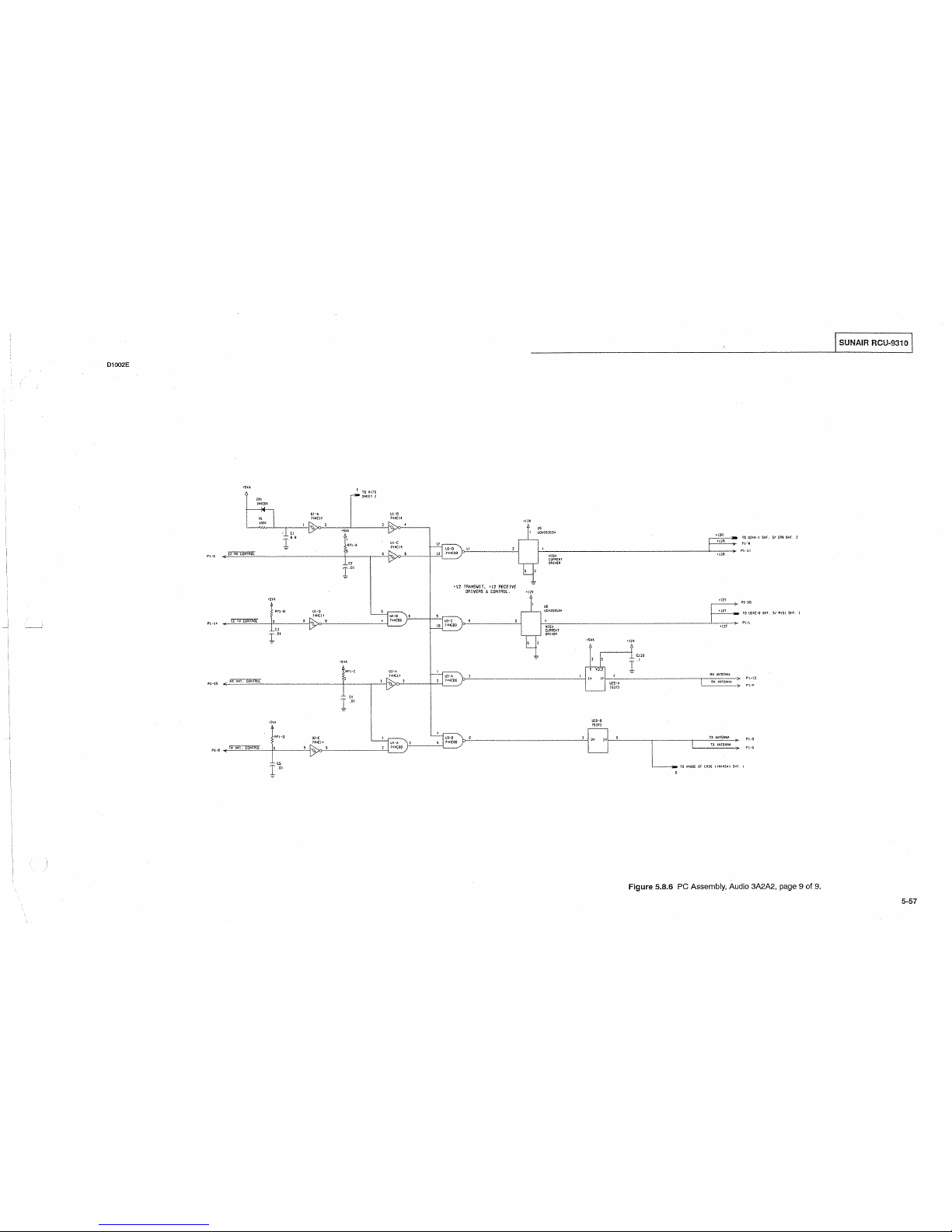
D1002E
ro
R\79
-SHEff
2
"'
\N~OOI
'
UhO.
U!·B
" I
14);(:14
l~llCII
\00(
,[>._
'
•»
.
P\•S
'i
i',
17
•SVA
17
'
RPI•A
UI·C
-
5
r>:H
12
RX
CO~lROl
'
"
17
r
•SVA
J
APJ·O
UI·O
'
r;;:_I!C\4
1
UI·S
\s
I~
IX
CO>!IRO[
,
' .
~
711!COB
_)
"
17
1
"
•SV"-
1\Pl·C
,_,
~C\4
fi,x
MH.
tONlRbl
' '
-<
1.7
1'1·15
"
1
·"
•SV.O..
RP\·0
U2·C
'
~((!<
llli·A
"\J
ff"W~
' ' '
2
74HC08
_/
17
L"
"
•t1V
"'
'
UON2935ZH
"
~
Ul·D II
'
'
13
7H'COO/
HJG>i
CIJ~RH/1
DRIVER
'
,
=
.,
TRANSMIT.
•12
RECEIVE
ORIVEAS
!.
CONTROL.
>12V
'
"
l.CNl935ZK
'
JUJ·C
•
'
'
1
W!COO
j"
lllGK
CURRHH
llRIVtA
'
,
=
'
lUH
\.
,
'
2
1•>1COO
j
·~
l
uJ-a
'
,
S 14H(00
~
•SVA
:l
E
v~c2
" "
'
U29•A
'--
1s:m
U2S·B
~
"
"
'
-
•12R
'l?A
,._
----->-
'l2A
•IZI
F
<l2T
.T
:!:
C!H
r'
AX
ANT€NNA
AX
ANIH<NA
U
AIITENNA
I
IX
ANlEN)!A
>-
TO
ANOOf
0~
CAJS
IINII54
I SKI
10 UH"-•1
$KT.
3/
tM
SHT.
2
I'J·U
Pl•\1
1'1·10
10
U2<C·9 SHI.
)/
AJSI
S~l.
I
P\·9
Figure
5.8.6 PC Assembly, Audio
3A2A2.,
page 9 of
9.
SUNAIR RCU-9310
5·57

I SUNAJR RCU-9310 I
PC ASSY, AUDIO REMOTE 3A2A4
(
PC ASSY, AUDIO REMOTE 3A2A4
8078085095
C1
CAP.
2.2/JF
1
35V,
T368 0273950002
C2 CAP.
15J1F,
15V, 196D 0281720002
C3
CAP.
15J1F,
15V,
196D 0281720002
C4
CAP.
15J1F,
15V, 196D
0281720002
C5
CAP.
15J1F,
15V, 196D 0281720002
CR1
DIODE, RECTIFIER 1N4004
0405180004
CR2
DIODE, RECTIFIER 1N4004 0405180004
K1
RELAY,DPDT,12VDC
1005090009
K2
RELAY, DPDT, 12VDC 1005090009
R1
POT. 1
OK,
10% 3/4W,
15
TURNS
0338490043
R2
RESISTOR
10K, 10%,
1/4W 0170410005
R3
RESISTOR
10K, 10%,
1/4W 0170410005
R4
RESISTOR
10K, 10%,
1/4W 0170410005
R5
RESISTOR
56K, 10%, 1/4W 0171440005
R6
RESISTOR 2.2K, 5%, 1/4W 0178070009
R7
RESISTOR
22,
10%, 1/4W 0192690001
R8
POT.
1K, 10% 3/4W, 15 TURNS 0338490019
R9
RESISTOR 1.5K, 10%, 1/4W 0172470005
R10 RESISTOR
10K, 10%,
1/4W 0170410005
T1
TRANSFORMER, AUDIO,
PC
MOUNT
0491650001
T2 TRANSFORMER, AUDIO, PC MOUNT
0491650001
U1
IC. LINEAR
5532 1006270019
(
1167AP
"
"
'
bOO@
1
2338
A55Y
NO.
"'
!
6076065095
I
p
r--
~)
'"
-c::J-
0
"'
'-._/
n
!
~
6
(.)DS
n
'--J
eoo
"'
0
e.
D
~
"
"
"
I
p
-c::J-
:
0cs
"
"
(
Figure 5.8.7 PC Assembly, Audio Remote 3A2A4, page 1 of
2.
5-58
I

A 1 !67 A
P\-2
'
-=
>12V
R4
Pl-5
!OK
+12V
'
[4
f 15
RlO
GNO
!OK
.,
c!?
Pl-4
1
NTERCOM
PJ-8
RCV
AUDIO
qzv
8
R3
!OK
5
~
r=-v-u;-:8
5532
'.L
[2
115
I
'
""'
3
'
1
,2-l:----/
R6
R5
2.2K
56K
R7
22
.
C3
I
15
R8
IK
":=
C5
15
I f
. '
R9
l.
SK
T1
1
~
T2
1
,_
_[''
~
t 8
r
5
~
r
8
I SUNAIR RCU-9310 I
"
3
XMll
A
2
I
'
I
5
XM!7
·s
7
L
""
P!-C
I
5
I
1
JN4004
4_:<tCR1
=
K2
3
R[V
A
2
PJ-5
I
4
I
6
RCV
8
7 j_
Pl-E
I
5
1
1
~
CR2
~
JN4004
-=
Figure
5.8.7 PC Assembly, Audio Remote 3A2A4, page 2 of
2.
5-59

I SUNAIR RCU-9310 I
PC ASSY,
1/0
BOARD 3A2A3
PC
ASSY, 1/0 BOARD 3A2A3 8076110092
C1
CAP.
.01!JF,
SOV,
X7R 20%
0281730008
C2
CAP.
6.SjJF,
20V, T368
0296780006
C3
CAP.
.01!JF, 50V,
X7R 20% 0281730008
C4
CAP.
.01!JF,
SOV,
X7R 20%
0281730008
cs
CAP.
.01!JF,
50V,
X7R
20%
0281730008
C6
CAP.
.01!JF, 50V,
X7R 20% 0281730008
C7
CAP.
.01!JF,
50V, X7R 20%
0281730008
C8
CAP.
.01!JF, 50V,
X7R 20% 0281730008
C9
CAP. 22jiF, 15V, 196D 0281690006
C10 CAP.
22jiF,
15V, 196D 0281690006
C11
CAP.
47!JF,
20V, 196D
0281700001
C12 CAP. .01jiF, 50V, X7R 20%
0281730008
C13 CAP.
.01!JF, 50V,
X7R 20% 0281730008
C14 CAP.
.01!JF,
SOV,
X7R
20%
0281730008
C15
CAP.
1
O!JF,
20V 1007290005
C16
CAP. 22jiF, 15V, 196D
0281690006
C17 CAP. 22jiF, 15V, 196D
0281690006
C18 CAP.
.01!JF, 50V,
X7R 20% 0281730008
C19
CAP.
47!JF,
20V, 196D 0281700001
C20 CAP.
.01!JF,
50V, X7R 20% 0281730008
C21
CAP.
.01!JF, 50V,
X7R 20% 0281730008
C22
CAP.
.01!JF,
50V, X7R 20% 0281730008
C23
CAP.
.01!JF,
50V, X7R 20% 0281730008
C24
CAP.
.01!JF,
SOV,
X7R 20% 0281730008
C25
CAP.
.01!JF,
50V, X7R 20% 0281730008
C26 CAP.
.01!JF,
50V, X7R 20%
0281730008
C27 CAP.
.01!JF,
50V, X7R 20% 0281730008
C28
CAP.
.01!JF,
50V, X7R 20% 0281730008
C29
CAP. .01!JF, 50V, X7R 20% 0281730008
C30 CAP.
.01!JF,
50V,
X7R 20% 0281730008
C31
CAP.
.01!JF,
50V, X7R 20% 0281730008
C32
CAP. .01jiF, 50V, X7R 20% 0281730008
C33 CAP.
.01!JF,
50V, X7R 20% 0281730008
C34
CAP.
.01!JF,
50V, X7R 20% 0281730008
C35 CAP.
.01!JF, 50V,
X7R 20% 0281730008
CR1
DIODE, LED, RED, PC MOUNT 1008480029
CR2
DIODE, RECTIFIER 1N4004 0405180004
CR3
DIODE, RECTIFIER 1N4004 0405180004
J1
CONNECTOR, POWER, 9 PIN FEMALE
1011090015
K1
RELAY,DPDT, 12VDC 1005090009
K2
RELAY,DPDT,12VDC
1005090009
L1
INDUCTOR, MOLDED,
33!JH,
5%
0659690004
L2
INDUCTOR, MOLDED,
33!JH,
5%
0659690004
L3
INDUCTOR, MOLDED,
33!JH,
5%
0659690004
L4
INDUCTOR, MOLDED,
33!JH,
5%
0659690004
LS
INDUCTOR, MOLDED,
33!JH,
5%
0659690004
L6
INDUCTOR, MOLDED,
33!JH,
5%
0659690004
L7
INDUCTOR, MOLDED,
33!JH,
5%
0659690004
L8
INDUCTOR, MOLDED,
33!JH,
5%
0659690004
L9
INDUCTOR, MOLDED,
33!JH,
5%
0659690004
Figure 5.8.8 PC Assembly, 1/0 Board 3A2A3, page 1 of
4.
5-60
P1
P2
01
02
R1
R2
R3
R4
RS
R6
R7
R8
R9
R10
R11
R12
R13
R14
R15
RP1
RP2
RP3
U1
U2
U3
U4
us
U6
U7
us
U9
U1o
U11
U12
U13
U14
U15
U16
U17
U18
U19
U20
XU9
XU10
XU20
CONNECTOR,
HEADER
40
PIN
CONNECTOR,
HEADER,
14
PIN
MALE
TRANSISTOR, NPN, Sl. 2N4124
TRANSISTOR, NPN, Sl. 2N4124
RESISTOR
680, 10%,
1/4W
RESISTOR 100K, 10%, 1/4W
RESISTOR
10K, 10%,
1/4W
RESISTOR
10K, 10%,
1/4W
RESISTOR
10K, 10%,
1/4W
RESISTOR 100K, 10%, 1/4W
RESISTOR
10K, 10%,
1/4W
RESISTOR 10K,
5%,
1/SW
RESISTOR 10K,
5%,
1/SW
RESISTOR
82, 10%, 1/4W
RESISTOR 10K,
5%,
1/SW
RESISTOR 68, 5%, 1/8W
RESISTOR 68,
5%,
1/8W
RESISTOR 68, 5%, 1/8W
RESISTOR 68, 5%, 1/8W
RES NTWK 10 PIN SIP 10K
COM
RES NTWK 10 PIN SIP 10K COM
RES
NTWK 10 PIN SIP 10K
COM
CRYSTAL OSCILLATOR, 7.3728MHZ
IC. DIGITAL
74HCOO
IC. DIGITAL
74HCOO
IC. DIGITAL 4078B
!C. DIGITAL
74HC374
IC. DIGITAL
74HC374
IC. DIGITAL
74HC04
IC. DIGITAL
74HC32
IC.DIGITAL
2681
IC. DIGITAL
80C85A
IC. DIGITAL
74HC138
IC. DIGITAL 74HC125
IC. DIGITAL 74HC373
IC. DIGITAL
74HC32
IC. DIGITAL
RAM
UPD446D
IC. DIGITAL
ICL232
IC. DIGITAL ICL232
IC. DIGITAL
75176
IC. DIGITAL
75176
EPROM, W/10 SOFTWARE RCU-9310
SOCKET, IC, 40 PIN TAILLESS
SOCKET,
IC,
40 PIN TAILLESS
SOCKET,
IC,
28 PIN TAILLESS
FERRITE
BEAD, 850 PERM
MOUNTING PLATE, 1/0 BOARD
I NOTE:!
U20
EPROM
is
not
partofPCASSY
I/OBOARD3A2A3P/N8076110092.
1010780000
(
1011210142
0448010003
0448010003
0176630007
0170390004
0170410005
0170410005
0170410005
0170390004
0170410005
1010801031
1010801031
0184610001
1010801031
1010806807
1010806807
1010806807
1010806807
1006130021
1006130021
1006130021
1008850012
1008190004
1008190004
1010460030
1006450033
1006450033
1010280023
(
1006470026
1008790010
1007400013
1006480013
1008810011
1006480030
1006470026
1006430008
1010510011
1010510011
1011100011
1011100011
8078113293
1006620010
1006620010
1006620001
1010410032
8076111200
(
I

1079P
!::!338
ASSY NO.
80761!0092
UJO
N
"
I SUNAIR RCU-9310 I
Figure
5.8.8 PC Assembly,
1/0
Board 3A2A3, page 2 of
4.
5-61

SUNAIR RCU-9310
Al079E
PI
28
U>C
I
·~
FlESET·OO
BOARO
AOOR€55
DECODER
lOIIi•
Ill
'"
" '
.0.15·08
~~,
r
9
HHCOO
" '
" '
PI
11
Pi
!J
PI
IS
p~
17
PI IS
Pi
JO
PI
20
" .
PI
JS
PI
Jj
PI
31
PI
29
PI
21
PI 25
PI
2J
PI
21
,,.
" '
"'
"""
~H·OB
'
A13·08
'
~
M2·08
'
"'
HHC401B
Ali·OB
'
~
~
)
"
AIO·Oa
"
~·W
"
et=
AB·OO
lfi•08
1
~·00
"""SHlSOI!<P
"'
nii[fi7IT
UO,IlEO
;;
~
..;...-
AOOOS
"'
AOIO!J
"'
A010!1
A(l308
AOlOil
AOSOB
AOliOB
Atl108
.,,
A
•SV
I
-<---
•SV
I
lo
r''
U8·1.
HllCJt
UJ·f
741<01
!!}"---
"
'"
~
Ui·O
)<HCO<
'
•
'"
t
"
'"
~te~
INPUT
"'
LATCH
"'""
13
10
HJ
"
""
"'"'
'
"
"
'
"'
"'""
•
"
'"
'
"'
MlJOS
,.
.,
"
"
"'
"'""
'
"
'"
•
"'
''""
"
"'
"'
"
'"
"""
'
"
'"
•
"'
1.01(18
..
"'
"'
"
"'
'-'!~
"~
Ut2·0
~
'-
Ul·B
•
"
'
HHCOO
US·B
7111C32
•
'
)
\.
'
UH•A
-
1i!<31
'"
I
uJ·C
•
'\
'
'
JIHCOO
,.,
,-2
HHC;J2
)
"
Y-
~
\
'
~
/
~
'
1H!()J
I
s
WiCOO_/
"'
I
OUTPUT
1~KCJ7l
LATCH
11
r-ot-
""
'"""'
"
'"
"
Al.ll08
'
"
"
'
<01
A020S
'
"
"
•
""
AOJOS
"
"
'"
"
"'
Ao•oa
'
"
'"
'
...
AOSOB
"
" "
"
""
AOSOS
•
"
'"
'
"'
AO:>oa
"
"
'"
"
"'
f.
'
-
..
I
IRP:/
~
IJO(
,-1,-
.-Is-
o
,-1,-
_J
'
"'
"'
""
"'
"'
"'
<01
""
Figure
5.8.8 PC Assembly, 1/0 Board 3A2A3, page 3 of
4.
5·62
(
TO
US·32
"'
"'
1.
)1261.1>2
10
119·3<
flSTO
"'"
.,.
PORT
A
'"'
'
aoss
..
INTERRUPT
~.._22_
'
'
"'
.,
LATCH
'"'
UH·C
,_
'
~
HHC32
X1
RSTO
\
'
"
ifslT.
'"
·-
-:,
"
"'
"'
100(
•
"
""'
flO
'\
'
..
""
~~
RP2•J
"'
" '
HHC!:lB
Ull·6
'"'
"
-"
m
'
A
'11~
HtO 1-{.0A
H~C32
10
I
"' '
'(']
13
TO
U9·35
'"
!NIA
!'lli'A
"
'
,_.i[i';i.Rf
'
TR?
!0/.\i
,.
"'
'
c
nr-!3-
IKKZ'~
Fro!J
US·!J
SHT.
2
"'
'
50
_19
"'
'
w
~r!L-
Al.S
CPU
'"
SflUIH
,_!__
51
-~
1
___._
"'
'
'"
....
FAQI,I
UJ•J
SHT.
2
•
Yiif-1-
•
AU"
30
"
RSTS
5
-
A5.5
"'
fAOIJ
AJ
S>!l.
2
''"
"
"
'"
IS<
U7·B
YJf-2.-
"'
"'
7HICOi
"'
"
"
...
!/0--;;;;;--
'
•
"'
"
"
"'
DECODER
'"
"'
"
"
m
•r
'
~
"'
"
,.
"'
..
"'
"
"
"'
"
' I
I
"' " "
""
•
I
"
'"
u
I
llPl
"'
"
"
..
'"
'"'
"'
"'
'
I
-
"'
'I
I
CPU
80AAO
...
•
I
INTERRUPT
"'
'
I
LATCH
L _
_j
~
/
/
...
"
"
\ "
ll2·0
'
•
~·
"
74fltC0
_/
1lHC!2S
"'"
Ul•A
I
"
1164
LOW
HHC04
AIS
(
ADDRESS
.
'"
'"
VPF
PfW
'""
I
~
'"
00
"
-
""
LATCH
"
iii'IC313
r+-
"
' "
A!:!l
lUJ-0
y
" "'
"
l4fiCOO
""
" "
'"
'
"
""
)0
10
RAM
55176
<01
'
'"
"
'
"
"
'
"
""
=--"'
"
"
"'
"'
'
' "
..
•
"
'"
.,
"
""
"
"
.,_
'"
"
"
.,
"'
'
'
"
..
5
"
"'
.,
"
'"
LJ!...
"
"
"'
'"
"
"
..
..
.
"
""
..
"
"
"'
" "
..
"
'
"
"'
"
'
"
"'
"
" "
" "
AOS
' '
.. ..
"
..
'
"
"
"'
'"
"
"
"'
"
"
"
.,
, .
..
'
"
AO~
"
'"
ADM
..
"
"'
"'
"
"
•
..
,.
"
...
I"
"'
"
"
'
"
"
"
'"
"'
'
"
'
"
"'
"' " "
rr1_•-
"
'
"
"
"
"'
"
•
" "
'
"'
~
"
-"'
A00·A01
S><f.
1
/
NOTE·
P l •
CPU
SOARD
P2•
SERIAL
!10
INTERFACE
(

Sl079E
RS!O
_,
fAOII
U!O·Jl
"'
2561
"'
""
'
'
'
"
------[i'"~'Q------'-1
~a 6~
'
"
'"
,...::'"o'o'"'"""-""---------'-'-1
"'
"
GtmiT
fRiJVliJI·lJ
;.fuH
2
SERII'/1
-;-----'~
\
7<HC00 ~ I
10
U!O·B
51<1.
I U
~
"'
'"
AO!l•A07
f~O~
SI-lL
I
'"
P2
1l
""
f
<
P2
10
..o:;
OETECJ
"'
""
"'
'"'
'"'
"'
"'
'""
U7·F
74HC0<
!!_
•
'
"
"
"
n
"
"
"
"
"
"
,,
"
RXO~
I
IXOA
"'
'"
"
"
~'
""
'"
IIHR
"'
"
"""
TXOS
'"
00
'"
-
"
30
"
"
f'!-
"
"
"
"
"
"
"
'
'
"
'
"
"
"
" '
"
"
!---""'--------'
"J
" '
SOT
-<
"'
M'.JOE
-<
'"
eJj
"'
""
'"
'"
"'
fS~
TO~E
"'
FS( ltlN!
-<
" '
'"'
1
I
z UlS
UIS
""
'"
TOX·1
""'
"
.2Sll'
'_,_1
!
e<O
r"'
"
"~
>-
" 6
~
C21
"
(
fiE
75115
f-'------,"":
~~'
=~~
\c•~oo~,~-~,===t====~:=:--i:-_!_'
ll
" '
IL
I
:~=
,.,
1
r=J
'-------r-~r---7
t 0
OR
IS
: : 3
'-------,--=~-,--j-J
~
"l
!NtOOt
"~
len
" '
b C2J
r"
"
r
"'"'
Rl2
1113
'='
0~
6S
SS
6
'
"
"'
IIODE~
Co
"
"
"'
'"
U12·C
)'•>1125
' '
Ul2·13
HH\25
J
"'
2N'I14
=
"
U!I·O
llC232
"
UP·C
llC2J2
UI5·F
lCL2J2
UII•A
ltDn
'
""
e'
RXO
~·
' '
r'----->
'
'
AHtfiENl:t
tAST
USED
"'
'"'
"
"
"
""
""
'"
Tc2•
f~;
,._
" .
r"
"
"~
l
06
" '
r:
r"
"
""'
1
C29
"'
r:
r"
"
""'
1
CJO
'
"
r:
r"
"
"""
l
(32
,._
"'
.t
CJJ
l.OI
"
r"
"'"'
1
(3(
'
"
.._!.
C3S
r·
r"
r,_
"
"
33UI~
r--c::
}
CONNJ:CtOR
HOUSI!<G
GflOUNO
O!:St(;~ATORS
Ufl.IS€0
qzv
"
"
I
'l2V
" "
UNUSED
ELEMENTS
UIG•C
!Ct2J1
111>-11
u1s·e
1Cl232
'1>-'
.,
MODE
FSK
TONE
RS-232
RS-422 RS-465
RS-232
8PS
300
300-~800
300-~EOO
~800
9600
08·9
PORT A PORT
A
'
PORT A PORT A PORT
9
I
TONE
XM!
2
TONE
ACV
3
XM!
4
ACV
s
GNO GNO GNO
GNO
GNO
6
XMT·H!GH
7
XMT
·LOW
0
RCV·H!GH
HIGH
9
RCV·LOW
LOW
CONNECTOR
CABLE
CABLE CABLE
CASLE
CAELE
HOUSING
SHIELD SH!ElO
SH!ELO
SHIELD SHIELD
9000
SERIES
REMOTE
CONTROL
CONNECTOR
PIN
SCHEDULE.
Figure 5.8.8
PC
Assembly,
1/0
Board 3A2A3, page 4 of
4.
SUNAIR RCU-931 0
5-63

I SUNAIR RCU-9310 I
C1
C2
C3
C4
C5
C6
P1
R1
R2
R3
R4
R5
T1
U1
X1
XP1
ZS1
PC ASSY, FSK MODEM 3A2A3A1
PC ASSY, FSK MODEM 3A2A3A1
CAP. 1
OpF,
20V
CAP. 0.001pF, 100V, X7R, 20%
CAPACITOR 0.1pF, 50V,
X7R
CAPACITOR
0.1J1F,
50V, X7R
CAPACITOR
0.1J1F,
50V, X7R
CAPACITOR
0.1J1F,
50V, X7R
CONNECTOR, RIBBON, 14 PIN FEM
RESISTOR 604, 1%, 1/8W
RESISTOR 5.6K, 5%, 1/8W
RESISTOR 10K, 5%, 1/8W
RESISTOR 10K, 5%, 1/8W
RESISTOR 10K, 5%, 1/8W
TRANSFORMER,
MODEM
!C. DIGITAL MC145443
CRYSTAL, 3.579545 MHZ
CONNECTOR,PCB,TRANSJTJON, 14PIN
VARISTOR, MOV V230LA20A
CABLE, FLAT, 14 COND. 28AWG
SCREW, PH4-40 X 5/16
LG.
WASHER, SPLIT
#4
WASHER, FLAT
#4
.219 OD
1159CP
0.'(=--_j"'
"~.nh
~
I
~0~
"
l
~
~o~l
~
~
Jc
c I
~
020e
"'
1
~~~C)
RJ
C2
Xl
8076115094
1007290005
0281630003
1011180014
1011180014
1011180014
1011180014
1008350001
0193980002
1010805622
1010801031
1010801031
1010801031
1011340011
1011330016
1006270001
1011090147
1010720023
1011170001
0500850054
0500020001
0502560002
Figure
5.8.9
PC
Assembly,
FSK
Modem
3A2A3A
1,
page 1 of
2.
5-64
(
(
(
 Loading...