


TM-8085000709
DIGITAL AUTOMATIC
ANTENNA COUPLER
CU-9125
OPERATION AND MAINTENANCE
MANUAL
SUNAIR 3005 SW Third Avenue, Ft. Lauderdale, FL 33315-3389

WARRANTY POLICY
GROUND AND MARINE PRODUCTS
Sunair Electronics warrants equipment manufactured by it to be free from
defects in material or workmanship, under normal use for the lesser of one (1)
year from the date of installation or 15 months from date of shipment by Sunair.
Sunair will repair or replace, at its option, any defective equipment or component
of the equipment returned to it at its factory, transportation prepaid, within such
warranty period. No reimbursement will be made for non-factory repair charges.
This warranty is void if equipment is modified or repaired without authorization,
subject to misuse, abuse, accident, water damage or other neglect, or has its
serial number defaced or removed.
THIS WARRANTY IS ESPECIALLY IN LIEU OF ANY AND ALL OTHER
WARRANTIES EXPRESSED OR IMPLIED, INCLUDING ANY IMPLIED
WARRANTY OF MERCHANTABILITY OR FITNESS FOR A PARTICULAR
PURPOSE. The obligation and responsibility of Sunair shall be limited to that
expressly provided herein and Sunair shall not be liable for consequential or
other damage or expense whatsoever therefore or by any reason thereof.
Sunair reserves the right to make changes in design or additions to or
improvements in its equipment without obligation to install such additions or
improvements in equipment theretofore manufactured.
SUNAIR ELECTRONICS, INC.

CU-9125
DIGITAL AUTOMATIC
ANTENNA COUPLER
SUNAIR
OPERATION
AND
MAINTENANCE MANUAL
FIRST EDITION, AUGUST 1, 1990
SECOND REVISION, JULY 1993
Page changes 1: 3/15/00

PRODUCT SERVICE:
PRODUCT SERVICE:
In case of difficulty please contact the Sunair
In case of difficulty please contact the Sunair
Product Service Department, between the hours
Product Service Department, between the hours
of 8:00 AM and 5:00 PM or write to:
of 8:00 AM and 5:00 PM or write to:
Product Service Dept.
Product Service Dept.
Sunair Electronics, Inc.
Sunair Electronics, Inc.
3101 SW Third Avenue
3101 SW Third Avenue
Ft. Lauderdale, FL 33315-3389
Ft. Lauderdale, FL 33315-3389
U.S.A.
U.S.A.
Telephone: (954) 525-1505
Telephone: (954) 525-1505
Fax: (954) 765-1322
Fax: (954) 765-1322
TRAINING:
TRAINING:
Sunair offers training programs of varying lengths
Sunair offers training programs of varying lengths
covering operation, service, and maintenance
covering operation, service, and maintenance
of all Sunair manufactured equipment. For
of all Sunair manufactured equipment. For
details please contact the Product Service
details please contact the Product Service
Department.
Department.

SUNAIR CU-9125
TABLE of CONTENTS
Section Description Page
I GENERAL INFORMATION
1.1 Scope
1.2 Description
1.2.1 General
1.2.2 Assemblies
1.2.2.1 Chassis Assembly 2A1
1.2.2.2 RF Assembly 2A2
1.2.2.3 Computer Board 2A3
1.2.2.4 Detector/Pad Assembly 2A4
1.3 Specifications
1.3.1 General
1.3.2 Environmental
1.4 Equipment Supplied
1.5 Equipment Required But Not Supplied
1.6 Optional Equipment Not Supplied
1-1
1-1
1-1
1-1
1-1
1-1
1-1
1-1
1-3
1-3
1-4
1-4
1-4
1-5
II INSTALLATION
2.1 General
2.2 Unpacking and Inspection
2.3 Return of Equipment to Factory
2.4 Power Requirements
2.5 Installation Considerations and Mounting Information
2.5.1 General Installation Procedures and Requirements
2.5.2 Mounting Considerations
2.5.2.1 Base Station Installation
2.5.2.2 Vehicular Installation
2.5.2.3 Marine Installation
2-1
2-1
2-1
2-2
2-2
2-2
2-3
2-3
2-3
2-3
i

SUNAIR CU-9125
TABLE of CONTENTS (Cont...)
Section Description Page
2.6 Antenna and Ground Systems
2.6.1 General
2.6.2 Narrow Band 50 Ohm Antennas
2.6.3 Random Length Non-resonant Antennas
2.7 Construction of Control Cable Assembly 8076004195
2.8 Checks After Installation
III OPERATION
3.1 Antenna Coupler Tuning
IV THEORY OF OPERATION
4.1 General
4.2 Antenna Tuning Network
4.3 Detector/Pad Assembly 2A4
4.3.1 General
2-9
2-9
2-9
2-10
2-12
2-14
3-1
4-1
4-1
4-1
4-3
4.3.2 Magnitude Discriminator
4.3.3 Phase Discriminator
4.3.4 Forward and Reflected Power Detector
4.3.5 6 dB Attenuator Pad Assembly
4.3.6 Tune Relay
4.4 Computer Board Assembly with Sleep Circuit
4.4.1 General
4.4.2 Phase Discriminator Interface
4.4.3 Magnitude Discriminator Interface
4.4.4 ‘RF Present’ Detector
4.4.5 VSWR Comparator
4.4.6 Reflected Power Meter Driver
4.4.7 Reference Voltage Sources
4.4.8 Tune Relay Latch
4-3
4-3
4-3
4-4
4-4
4-4
4-4
4-5
4-5
4-5
4-5
4-6
4-6
4-6
ii

SUNAIR CU-9125
TABLE of CONTENTS (Cont...)
Section Description Page
4.4.9 Microprocessor Circuits
4.4.9.1 General
4.4.9.2 Microprocessor U1
4.4.9.3 Address Decoder U2
4.4.9.4 Address Latch U3
4.4.9.5 Erasable Programmable Read Only Memory
(EPROM) U4
4.4.9.6 Input Port
4.4.9.7 Output Ports
4.4.9.8 Timer
4.4.9.9 Random Access Memory (RAM)
4.4.9.10 Electrically Erasable Programmable Read
Only Memory (EEPROM) U14
4.5 Chassis Assembly 2A1
4.5.1 General
4-6
4-6
4-6
4-7
4-7
4-7
4-8
4-9
4-10
4-10
4-10
4-10
4-10
4.5.2 RF Assembly 2A2
4.5.3 Motherboard 2A1A1
V ALIGNMENT
5.1 General
5.2 Preventive Maintenance
5.3 Inspection
5.4 Repair or Replacement
5.4.1 General Precautions
5.4.2 Circuit Card Assembly, Two-Lead Component
4.5.2.1 General
4.5.2.2 Theory of Operation
Removal
4-10
4-10
4-11
4-11
5-1
5-1
5-1
5-3
5-3
5-3
iii

SUNAIR CU-9125
TABLE of CONTENTS (Cont...)
Section Description Page
5.4.3 Circuit Card Assembly, Multi-lead Component
Removal
5.4.4 Removal of Components of Doubtful Condition
5.5 Performance Test
5.5.1 Test Equipment
5.5.2 Preliminary
5.5.3 CU-9125 Alignment Procedure for Computer
Board Assembly 2A3
5.5.4 Alignment Procedure for Detector/Relay Pad
Assembly 2A4
5.6 Schematics and Parts Lists
5-3
5-4
5-4
5-4
5-5
5-6
5-9
5-44
iv

SUNAIR CU-9125
LISTING of FIGURES
Section Description Page
I GENERAL INFORMATION
1.1 CU-9125 Major Assembly Locations. 1-2
II INSTALLATION
2.1 Outline Mounting Details CU-9125. 2-4
2.2 Shockmount Installation. 2-5
2.3 Typical Base Station Installation
Using Non-Resonant Antennas. 2-6
2.4 Typical Vehicular Installation. 2-7
2.5 Coupler Grounding. 2-8
2.6 Whip Antenna. 2-10
2.7 Inverted “V” Antenna. 2-11
2.8 Longwire Antenna. 2-11
2.9 Wiring Diagram, Control Cable (8076004195). 2-13
IV THEORY OF OPERATION
4.1 CU-9125 Block Diagram. 4-2
V ALIGNMENT
5.1 Antenna Coupler Cover Removal. 5-2
5.2 Computer Board Test Point and Adjustment Locations. 5-6
5.3 Detector Pad (2A4) and Extender Card Test Point
and Adjustment Locations. 5-8
5.4 Coupler Test. 5-10
5.5 Major Assembly and Component Locations
(Front View). 5-12
5.6 Major Assembly and Component Locations
(Top View). 5-13
5.7 Major Assembly and Component Locations
(Bottom View). 5-14
5.8 Major Assembly and Component Locations
(Right Side View). 5-15
v

SUNAIR CU-9125
LISTING of FIGURES (Cont...)
Section Description Page
5.9 Major Assembly and Component Locations
(Left Side View). 5-16
5.10 Front Panel Wiring Diagram. 5-17
5.11 Motherboard Assembly 2A1A1, page 1 of 3. 5-47
5.11 Motherboard Assembly 2A1A1, page 2 of 3. 5-48
5.11 Motherboard Assembly 2A1A1, page 3 of 3. 5-49
5.12 Input Board 2A2A1, page 1 of 2. 5-50
5.12 Input Board 2A2A1, page 2 of 2. 5-51
5.13 Intermediate Board 2A2A2, page 1 of 2. 5-52
5.13 Intermediate Board 2A2A2, page 2 of 2. 5-53
5.14 Inductor Board 2A2A3, page 1 of 2. 5-54
5.14 Inductor Board 2A2A3, page 2 of 2. 5-55
5.15 Output Board 2A2A4, page 1 of 2. 5-56
5.15 Output Board 2A2A4, page 2 of 2. 5-57
5.16 Computer Board Assembly 2A3, page 1 of 6. 5-58
5.16 Computer Board Assembly 2A3, page 2 of 6. 5-59
5.16 Computer Board Assembly 2A3, page 3 of 6. 5-60
5.16 Computer Board Assembly 2A3, page 4 of 6. 5-61
5.16 Computer Board Assembly 2A3, page 5 of 6. 5-62
5.16 Computer Board Assembly 2A3, page 6 of 6. 5-63
5.17 Detector/Relay Pad Assembly 2A4, page 1 of 2. 5-64
5.17 Detector/Relay Pad Assembly 2A4, page 2 of 2. 5-65
5.18 TS-100 Antenna Simulator Schematic. 5-66
vi

SUNAIR CU-9125
LISTING of TABLES
Section Description Page
IV THEORY OF OPERATION
4.1 Magnitude Discriminator Truth Table 4-8
4.2 Phase Discriminator Truth Table 4-8
4.3 Truth Table BCD Channels 00-09 4-9
V ALIGNMENT
5.1 Fault Analysis 5-11
5.2 Fault Analysis and Troubleshooting Computer Board 2A3 5-19
5.3 Table of Assemblies 5-44
5.4 Parts List of CU-9125 Major Assemblies 5-45
vii

SUNAIR CU-9125
TABLE of ABBREVIATIONS
ADDR Address
AGC Automatic Gain Control
ALC Automatic Level Control
AM Amplitude Modulation
AME Amplitude Modulation Equivalent
AMP/AMPL Amplifier
ARQ Automatic Request
AUD Audio
AUTO Automatic
AUX Auxiliary
BAUD A variable unit of data transmission speed (bits
per second)
BELL U.S. Telephone standards
BFO Beat Frequency Oscillator
BITE Built In Test Equipment
BRD Board
CH /CHAN /CHL/CHN Channel
CLR Clear
CMOS Complementary Metal Oxide Semiconductor
CPLR Coupler
CPU Computer
CW Carrier Wave
dB Decibel
dBm Decibels referred to 1 milliwatt across 600 ohms
DSBSC Double Sideband Suppressed Carrier
DSP Display
DUART Dual Asynchronous Receive/Transmit
EEPROM Electrically Erasable and Programmable Read
Only Memory
EPROM Electrically Programmable Read Only Memory
EMI Electromagnetic Radiation Interference
ENTR Enter
FAX Facsimile
FEC Forward Error Correction
FREQ Frequency
FSK Frequency Shift Keying
FWD Forward
GRP Group
HF High Frequency
Hz Hertz
IC Integrated Circuit
IF Intermediate Frequency
I/O Input/Output
IONCAP Ionospheric Communications Analysis
and Prediction
kHz Kilohertz
kW Kilowatt
ISB Independent Sideband
LCD Liquid Crystal Display
LCL Local
LED Light Emitting Diode
LK Link
LO Local Oscillator
LP/LPX Lincompex
LRU Lowest Repairable Unit
LSB Lower Sideband
LT Light
LVL Level
MAN Manual
M CH Manual Channel
MED Medium
MHz Megahertz
MIC Microphone
MIL-STD Military Standard
MNL Manual
ms Millisecond
MTTR Mean Time To Repair
MTR Meter
NAR Narrow
O.D. Olive Drab
PA Power Amplifier
PC Printed Circuit
PEP Peak Envelope Power
PLL Phase-Locked Loop
P/N Part Number
PNL Panel
POSTSL Post-Selector
PRESEL Pre-Selector
PTT Push-To-Talk
PWR Power
RCV/RX Receive
REFL Reflected
REV Revision
RF Radio Frequency
RFI Radio Frequency Interference
RFL Reflected
RMT Remote
RS232 Computer control, hardwired up to 50 feet maximum
RS422 Computer control, hardwired up to 4000 feet
maximum
RS485 Computer control, hardwired for multiple users
RTTY Radio Teletype
SEL Select
SLO Slow
S MTR Signal Strength Meter
SPKR Speaker
SPLX Simplex
SRAM Static Random Access Memory
SSB Single Sideband
TCXO Temperature Controlled Crystal Oscillator
TGC Transmit Gain Control
THD Total Harmonic Distortion
TTL Transistor Transistor Logic
TX/XMT Transmit
USB Upper Sideband
UTC Universal Time
VCO Voltage Controlled Oscillator
VHF Very High Frequency
VRMS Volts Root Mean Square
VSWR Voltage Standing Wave Ratio
W Watt
WPM Words Per Minute
* Asterisk indicates function selected

SUNAIR CU-9125
SECTION I
GENERAL INFORMATION
1.1 SCOPE
This manual contains information necessary to install, operate, maintain and repair the CU-9125 Automatic Digital
Antenna Coupler.
1.2 DESCRIPTION
See Figure 1.1
1.2.1 GENERAL
The CU-9125 is a high quality remotely controlled antenna coupler capable of matching a wide variety of
antennas ranging from 9 ft. whips to 150 ft. longwires over the frequency range of 1.6000 to 29.9999 MHz. In
addition, the coupler may be used as a “line flattener” to correct the VSWR of resonant antennas.
The CU-9125 is designed to operate in conjunction with the Sunair 9000 Series Equipment utilizing Cable
Assembly p/n 8076004098 at separations of up to 250 feet. Manual tuning cycles are initiated by depressing
the “CPLR TUNE” pushbutton on the 9000 Series Transceiver or Exciter. Tuning status metering for indicating
forward and reflected power are located on the radio equipment. The coupler is mounted in a sturdy, fully
gasketed case designed for outside mounting near the antenna.
1.2.2 ASSEMBLIES
1.2.2.1 CHASSIS ASSEMBLY 2A1
The Chassis Assembly provides the required mounting surfaces for the various electrical and mechanical
components. The Motherboard 2A1A1 serves as the interconnect for all assemblies.
1.2.2.2 RF ASSEMBLY 2A2
The four (4) boards comprising the RF Assembly are the Input Board 2A2A1, the Intermediate Board 2A2A2,
the Inductor Board 2A2A3 and the Output Board 2A2A4. The boards contain all of the variable binary elements
in the antenna matching network.
1.2.2.3 COMPUTER BOARD 2A3
This assembly contains the microprocessor responsible for the operation and functions of the CU-9125.
1.2.2.4 DETECTOR/PAD ASSEMBLY 2A4
The Detector Assembly 2A4A1 contains the magnitude, phase and VSWR detectors. The Pad Assembly
2A4A2 plugs into the Detector Assembly and protects the Transceiver/Exciter from impedance variations during
the tuning cycle.
1-1

SUNAIR CU-9125
OUTPUT BOARD
2A2A4
INDUCTOR BOARD
2A2A3
DETECTOR/PAD ASSEMBLY
2A4
TOP VIEW W/O COVER
INTERMEDIATE BOARD
2A2A2
INPUT BOARD
2A2A1
FAN ASSEMBLY
P/0 CHASSIS ASSEMBLY
2A1
1-2
MOTHERBOARD
2A1A1
COMPUTER BOARD
2A3
BOTTOM VIEW W/O COVER
Figure 1.1 CU-9125 Major Assembly Locations.

SUNAIR CU-9125
1.3 SPECIFICATIONS
1.3.1 GENERAL
FREQUENCY RANGE: 1.6 to 30 MHz.
TUNING CAPABILITIES: 9 ft. whips
16 ft. whips
23 ft. whips
35 ft. whips
50 ft. to 150 ft. longwires
suitable as a line flattener for broadband antennas
RF INPUT POWER: 150 Watts PEP and AVERAGE.
INPUT IMPEDANCE: 50 Ohms, non-reactive.
DUTY CYCLE: Continuous for antennas 23 feet and longer. Fifty percent (maximum 5 minutes
continuous key down time) for 9 and 16 ft. antennas.
TUNING TIME: Memory Tuning - 10 milliseconds or less.
Non-Memory Tuning: - Typical: 1 second.
Maximum: 10 seconds.
Memory: Non volatile, 128 channels (00 - 127).
TUNE POWER REQUIRED: 25 Watts RF delivered.
TUNE ACCURACY: 1.5:1 VSWR maximum.
REMOTE CAPABILITY: Up to 250 ft. from Transceiver/Exciter.
POWER INPUT: +28 VDC from Transceiver/Exciter, 1 Amp maximum.
WEIGHT: 23 lbs (10.35 kgs).
DIMENSIONS: (Inches) 9.1H X 9.6W X 11.4D.
(CM) 23.1H X 24.4W X 28.96D.
1-3

SUNAIR CU-9125
1.3.2 ENVIRONMENTAL
TEMPERATURE: Operating: -30oC to +65oC.
Storage: -50oC to +85oC.
HUMIDITY: MIL-STD 810C, Method 507.1, Procedure II.
SHOCK: MIL-STD-810C, Method 516.2, Proc I, Figure 516.2-2, Ampl. b (20 g.), Dur.d.
VIBRATION:MIL-STD-810C, Method 514.2 equipment category f, Table 514.2-VI for wheeled vehicles, Figure
514.2-6, curve V.
DUST: MIL-STD-810C, Method 510.1, Procedure I.
RAIN: MIL-STD-810C, Method 506.1, Procedure I.
PACKAGING: Rain tight, for exposed installations.
1.4 EQUIPMENT SUPPLIED
Automatic Digital Antenna Coupler, CU-9125,
Connector Kit,
Operation and Maintenance Manual,
1.5 EQUIPMENT REQUIRED BUT NOT SUPPLIED
Control Cable Assembly:
Order by length desired. The Coupler will operate with up
to 250 ft. of remote control cable.
Cable, Control. Specify length.
Cable, Coaxial, RG-58A/U:
Recommended where separation between Transceiver/
Exciter and Coupler is less than 100 ft. Specify length.
Cable, Coaxial, RG-8/U:
Recommended where separation between Transceiver/
Exciter and Coupler exceeds 100 ft. Specify length.
SUNAIR PART NUMBER
8085000253 Grey
8085000296 Olive Drab
6035002099
8085000709
8076004195
0588680001
0588130001
0588640000
1-4
Cable, Coaxial, RG-213:
Same as RG-8/U.
Connector, RF, PL-259:
Mates with antenna connector J4 on 9000 Series.
1010770021
0742190005

1.6 OPTIONAL EQUIPMENT NOT SUPPLIED
SUNAIR CU-9125
Transceiver/Exciter
Shockmount Kit - CU-9125
PC Assy, Extender CU-9125
Depot Spare Parts Kit
Field Module Kit
PC Assy, Detector Extender Board
Antenna Simulator Model TS-100
Consult Sunair Marketing Dept.
8080000492
8080002096
8085900092
8085902095
8085165091
8084001094
1-5

SUNAIR CU-9125
THIS PAGE INTENTIONALLY LEFT BLANK.
1-6

SUNAIR CU-9125
SECTION II
INSTALLATION
2.1 GENERAL
Section II contains all necessary instructions for the unpacking, inspection, and if necessary, reshipping of
damaged equipment or parts. In addition, further information regarding location and mounting considerations,
power requirements, antenna and ground system hook-ups and final checkouts after installation is also provided.
2.2 UNPACKING AND INSPECTION
As soon as you have received your unit(s), unpack and inspect all components and accessories. Check the packing
list to be sure you have received all items ordered and that all items necessary for operation have been ordered.
NOTE: Be sure to retain the carton and its associated packing materials
should it be necessary to reship damaged equipment.
Do not accept a shipment when there are visible signs of damage to the cartons until a complete inspection is made.
If there is a shortage of items or any evidence of damage, insist on a notation to that effect on the shipping papers
before signing the receipt from the carrier. If concealed damage is discovered after the shipment has been
accepted, notify the carrier immediately in writing and await his inspection before making any disposition of the
shipment. A full report of the damage should also be forwarded to Sunair’s Product Services Department. Include
the following:
a) Order Number
b) Model and Serial Number
c) Name of Transportation Agency
d) Applicable dates.
When Sunair receives this information, arrangements will be made for repair or replacement.
2.3 RETURN OF EQUIPMENT TO FACTORY
The shipping container for the CU-9125 has been carefully designed to protect the equipment during shipment. The
container and its associated packing materials should be used to reship the unit. When necessary to return
equipment to Sunair for warranty or non-warranty repair, an authorization number is required. This number can
be obtained from our Product Services Department, Telephone: (954)-525-1505, FAX: (954)-765-1322.
If the original shipping carton is not available, be sure to carefully pack each unit separately, using suitable
cushioning material where necessary. Very special attention should be given to providing enough packing material
around connectors and other protrusions from the coupler. Rigid cardboard should be placed at the corners of the
equipment to protect against denting.
When returning subassemblies or components for repair or replacement, be sure to pack each item separately,
using suitable cushioning material.
2-1

SUNAIR CU-9125
Shipment to be made prepaid consigned to:
Sunair Electronics, Inc.
Product Services Department
3101 SW Third Avenue
Ft. Lauderdale, Florida 33315-3389
U.S.A.
Plainly mark with indelible ink all mailing documents as follows:
U.S. Goods Returned For Repair
Value For Customs - $100.00
Mark ALL SIDES of the package:
FRAGILE - ELECTRONIC EQUIPMENT!
NOTE: Before shipping, carefully inspect the package to be sure it is marked
properly and is securely wrapped.
2.4 POWER REQUIREMENTS
All power necessary to operate the CU-9125 Automatic Digital Antenna Coupler is supplied from a companion
Exciter/Transceiver via the Control Cable Assembly. See Figure 2.8 for control cable connections. If an Exciter/
Transceiver other than a Sunair model is used, an external power source of +28VDC at 1.0 amp is required to power
the CU-9125.
2.5 INSTALLATION CONSIDERATIONS AND MOUNTING INFORMATION
The satisfactory operation of the equipment will depend upon the care and thoroughness taken during the
installation.
IMPORTANT INSTRUCTIONS
2.5.1 GENERAL INSTALLATION PROCEDURES AND REQUIREMENTS
1. Carefully plan radio/coupler/antenna locations, observing the following requirements before starting
installation.
2. Provide best possible RF ground for radio and coupler. Use flat copper strap 1" wide or #6 (or larger) wire
and connect to the ground terminal at rear of radio. Leads to ground system should be as short as possible.
3. Provide the maximum separation between coupler output and the radio with its associated wiring. Coupler
may be mounted up to 100 feet from radio when RG-58 is used, and up to 250 feet from radio when RG-8 or
RG-213 is used.
4. The antenna lead from the coupler to antenna must be insulated for at least 10 kv potential. The lead should
not run parallel to metal objects that are bonded to the system ground. The coupler should be as close to the
antenna as possible, and never more than three (3) feet away as this will decrease antenna efficiency.
5. If the coupler is installed on a wood or fiberglass boat, a 12 square foot minimum area of metal surface
area in contact with the water should be provided for use as an RF ground.
2-2

SUNAIR CU-9125
6. If operating the coupler on external DC power, check for correct polarity before applying power.
7. The installation should be carefully planned beforehand in accordance with drawings on the following
pages.
8. Linear amplifiers with low level modulation such as used in Sunair Exciters/Transceivers will oscillate if the
RF power output is radiated or conducted into the low level stages. Evidence of this situation is erratic or
excessive power output. This is caused by too close proximity of the coupler output and antenna to the
Transceiver/Exciter and/or inadequate RF grounds. Carefully following the above procedures will prevent this
from occurring.
2.5.2 MOUNTING CONSIDERATIONS
See Figure 2.1 for Coupler dimensions.
2.5.2.1 BASE STATION INSTALLATION
A typical base installation consisting of an RT-9000 and a CU-9125 is shown in Figure 2.3. (Consult the RT-
9000 Operation and Maintenance Manual, p/n 8076000505, for installation details for the Transceiver.) The
CU-9125 can also be used with the T-9400 HF/ISB Exciter. (Consult the T-9400 HF/ISB Exciter Operation
and Maintenance Manual, p/n 8103000507, for installation details.) Refer to Section 2.6 for recommendations
for suitable antennas.
2.5.2.2 VEHICULAR INSTALLATION
Figure 2.4 shows a typical vehicular installation with an RT-9000 Transceiver and shockmount assembly.
NOTE: Shockmounting is required only in severe shock or vibration
environments exceeding those noted in Section 1.3.2. See
Figure 2.2 for installation.
See Section 2.6 for specific antenna recommendations. In order to minimize RF pickup, it is important that the
ground straps supplied with the shockmount, if used, be securely fastened between the ground post on the radio
and the bottom of the right rear shock isolator. (Consult the RT-9000 manual for further details.)
2.5.2.3 MARINE INSTALLATION
In marine installations, follow the same recommendations as outlined in paragraph 2.5.2.2 above. If the radio
is installed in a wood or fiberglass boat, a ground plate of 12 square foot minimum area in contact with the water
should be installed. A heavy ground lead such as 1 inch wide strap or braid should be connected between the
ground post on the radio and the ground plate. The length of this ground lead should be held to an absolute
minimum commensurate with a neat installation.
2-3

SUNAIR CU-9125
2-4
Figure 2.1 Outline Mounting Details CU-9125.

SUNAIR CU-9125
Figure 2.2 Shockmount Installation.
2-5

SUNAIR CU-9125
2-6
Figure 2.3 Typical Base Station Installation Using Non-Resonant Antennas.

SUNAIR CU-9125
Figure 2.4 Typical Vehicular Installation.
2-7

SUNAIR CU-9125
2-8
IMPORTANT NOTE:
In some installations, it may be necessary to install the CU-9125 adjacent to the
radio. Grounding is extremely important to prevent RF from feeding back into the
radio. The CU-9125 should be grounded to the front ground strap, as shown
above. In addition, the ground braid used on the rear of the radio should be as
short as possible. The interconnecting cable from the radio to the CU-9125
should be as short as possible and should not be routed under the antenna feed
wire.
Figure 2.5 Coupler Grounding.

SUNAIR CU-9125
2.6 ANTENNAS AND GROUND SYSTEMS
2.6.1 GENERAL
Sunair Exciters/Transceivers are designed to operate into a 50 Ohm resistive antenna system with a maximum
voltage standing wave ratio (VSWR) of 2:1. When used with the CU-9125 Automatic Digital Antenna Coupler
the system will match antennas ranging from 9 foot whips to 150 foot longwires. Although the CU-9125 will match
9 foot whips down to 1.6 MHz, use of a 9 foot whip is not recommended for low frequency use due to poor
radiation efficiency. The CU-9125 is unique in that it can be placed close to the antenna and controlled from the
front panel of the Exciter/Transceiver. This optimizes both operator convenience and electrical performance.
As there are numerous types of antennas, a complete discussion is beyond the scope of this manual. Antennas
requiring an antenna coupler for use in the 1.6 to 30 MHz spectrum generally fall into two categories:
a) Narrow Band 50 Ohm Antennas
b) Random length non-resonant Antennas.
Antennas falling into each of the above mentioned categories are discussed in this section. For specific
recommendations, consult our Marketing and Product Support Departments.
Some general DOs and DON'Ts of antenna installation are listed below:
a) The antenna should be clear of all large objects such as trees and buildings.
b) Although the coupler will match electrically short antennas (i.e. those under 1/8 wavelength), such
antennas are not efficient radiators. If the installation permits, antennas over 1/8 wavelength long at the lowest
operating frequency should be used. Antenna length generally limits system performance in vehicular
applications at frequencies below 10 MHz as the size would be prohibitive.
c) When using whip antennas, the ground system actually forms part of the radiating system. Where space
permits (such as in a base station installation) a good ground plane or radial system should be installed at the
base of the antenna. (See Figure 2.6)
NOTE: An inadequate ground system is most often responsible for
disappointing performance when using a whip antenna.
2.6.2 NARROW BAND 50 OHM ANTENNAS
Typical of this type of antenna is the Inverted V illustrated in Figure 2.7. This type of antenna may be assembled
from the Sunair Doublet Antenna Kit (p/n 0996240004). Its operation is efficient for only a narrow band of
frequencies within approximately 2½% of their center frequency. The antenna coupler is NOT generally
required if the above frequency span is not exceeded. Separate antennas must be erected for each small band
of frequencies to be used. The antenna exhibits somewhat directional characteristics. The direction of
maximum radiation is perpendicular to the antenna wire. This antenna is particularly suitable for communication
with nearby mobile stations (with vertical antennas) since a portion of the radiation is in a vertical direction.
2-9

SUNAIR CU-9125
2.6.3 RANDOM LENGTH NON-RESONANT ANTENNAS
Whips and longwires are popular non-resonant antennas. The whip antenna (illustrated in Figure 2.6), is often
used in mobile, marine, portable or semi-portable installations because it is rugged and self- supporting. The
antenna impedance is strongly dependent on the operating frequency, and an antenna coupler, therefore, must
be used to match the antenna to the Transceiver/Exciter. Best radiation efficiency will be obtained if the antenna
is at least 1/8 wavelength long at the lowest operating frequency; however, this requirement does not result in
a practical size antenna for low frequency operation. Thirty-five foot whip antennas offer a good compromise
between practical height and good electrical performance at low frequencies. The antenna coupler is designed
to efficiently match whip antennas of 15 foot length or greater. An efficient match may also be obtained for a
9 foot whip above 4 MHz. The whip’s performance is greatly influenced by its ground system. For temporary
base station installations, a minimum of four six-foot long ground rods should be driven into the ground
symmetrically placed around the antenna base. The rods should be bonded together with heavy strap and then
connected to the antenna coupler ground by another short heavy strap. If the antenna is mounted on the roof
of a building where a short ground lead to coupler cannot be obtained, a minimum of four symmetrically placed
ground radials should be installed at the base of the antenna, bonded together, and connected to the antenna
coupler ground post. The radials should be made of number 12 gauge wire or larger and should be at least ¼
wave long at the lowest operating frequency. (Radial length in feet = 246/frequency in MHz.) The whip’s
radiation pattern is omni-directional in the azimuthal plane.
The longwire antenna, illustrated in Figure 2.8, is a popular base station antenna where a wide range of operating
frequencies are used. The antenna impedance varies greatly with frequency and, therefore, must be matched
to the transmitter with the antenna coupler. The CU-9125 Antenna Coupler will efficiently match longwire
antennas up to 150 foot in length. The radiation pattern of the longwire antenna is also a strong function of
operating frequency. The two most popular longwire antennas, (75 and 150 foot) available from Sunair, exhibit
excellent low frequency radiation efficiency.
2-10
Figure 2.6 Whip Antenna.

SUNAIR CU-9125
Figure 2.7 Inverted ‘V’ Antenna.
Figure 2.8 Long Wire Antenna.
2-11

SUNAIR CU-9125
2.7 CONSTRUCTION OF CONTROL CABLE ASSEMBLY 8076004195
It is recommended that the control cable assembly be procured from Sunair. However, if necessary, the cable may
be made from individual wires of #20 AWG with an overall braided shield and PVC jacket.
The control cable assembly may be shipped from the factory without connectors attached to facilitate the routing
of this cable through walls, bulkheads, conduit, etc. After installing the cable, follow the procedure outlined below.
NOTE: The connector with the male pins (1011130009) should be wired at
the transceiver end of the cable.
The connector with female pins (0747690008) should be wired at the
coupler end of the cable. Refer to Figure 2.8
1. Loosen both screws on one of the cable clamps.
2. Insert the rubber telescoping bushing (boot) through the rubber grommet on the inside of the cable clamp
and push through until the lip on the boot bottoms on the rubber grommet. The boot should extend beyond the
cable clamp.
3. Insert the cable (0588680001) into the open end of the boot and cable clamp and pull through until
approximately six inches of cable extends from the inside of the cable clamp.
4. Carefully remove approximately 1½ inches of the plastic outer jacket of the remote control cable using a
knife or razor blade. Use care so as not to damage the shield or inner conductors.
5. Carefully unbraid the cable shield to within approximately ¼ inch of the outer jacket. Carefully cut the
unbraided shield wires at this point using a pair of small wire cutters.
6. Remove approximately one inch of insulation from the end of a three-inch piece of #22 gauge hook-up wire.
Wrap the wire around the outer jacket and solder the connection using a medium-size soldering iron. Attach
a #8 solder lug to the other end of the wire, after pulling the wire back through the telescoping bushing.
7. Note the mylar sleeve over the wire bundle. Carefully cut this sleeve, being careful not to nick the wires
in the bundle, until the wire bundle is exposed back to the end of the shield.
8. Flare out the bundle of wires and separate the individual wires. Strip approximately 1/8 inch of insulation
from each wire.
9. Choose one of the wires and carefully tin it. Solder the wire to one of the cups of the connector. Make a
chart showing the wire color code and pin connection.
10. Proceed in a similar manner until all required wires are installed.
11. When all connections are completed, screw the rear shell and cable clamp assembly on the connector and
tighten. Push a small additional amount of cable into the connector to ensure some slack. Remove one cable
clamp screw and insert the lug on the #22 shield wire. Reinsert screw into cable clamp. Tighten the two screws
on the cable clamp.
12. Follow an identical procedure to connect the other end of the cable to the proper pin as shown in Figure
2.9.
2-12

SUNAIR CU-9125
WARNING: Connectors installed by the customer must be wired in accordance
with the instructions provided in this section. The cable MUST BE continuity
checked after connector installation and prior to system power up.
Figure 2.9 Wiring Diagram, Control Cable Assembly (8076004195).
2-13

SUNAIR CU-9125
2.8 CHECKS AFTER INSTALLATION
9000 Series Exciters/Transceivers
1. Select a frequency in the 2 to 3 MHz range (or a frequency you are allowed to use).
2. Upon initial power on, the LCD will display function and status of the radio. An alternating ‘Coupler Untuned’
message will appear on the screen.
3. Depress the ‘CPLR TUNE’ pushbutton.
4. While coupler is tuning, screen will display ‘Coupler Tuning’.
5. When a successful tune has been completed (1-2 seconds), screen will display ‘System Ready’ and then
return to normal display status. If a ‘System Fault’ or ‘Coupler Fault’ message is displayed see section 3.1.
2-14

SUNAIR CU-9125
SECTION III
OPERATION
3.1 ANTENNA COUPLER TUNING
Once an operating frequency has been selected the exciter or transmitter section of the Transceiver is
automatically tuned to the same frequency (Simplex Operation). If the Transceiver/Exciter output is fed to an
Antenna Coupler (CU-9125), depression of the ‘CPLR TUNE’ key, will initiate the tune cycle. During this time
(a few seconds or less), the message
’COUPLER TUNING‘
will appear on the Status Display Screen. When coupler tuning has been completed, the message
‘SYSTEM READY’
will appear on the Status Display Screen.
THE TRANSCEIVER/EXCITER IS NOW FULLY OPERATIONAL
NOTE: If there is no antenna coupler in the system, depression of the ‘CPLR
TUNE’ key will produce the message
‘NO ANTENNA COUPLER’
on the Operational Display Screen.
NOTE: If the coupler is unable to tune the antenna within 10 seconds, the
message
‘SYSTEM FAULT’
will appear on the Status Display Screen. If this occurs, check the
installation and the antenna. If all appears in order, proceed to the
troubleshooting section of the coupler manual.
NOTE: If the coupler remains in the tune mode for longer than 10 seconds
the message
‘COUPLER FAULT’
will appear on the Status Display Screen. If this occurs, proceed to
the troubleshooting section of the coupler manual.
3-1

SUNAIR CU-9125
THIS PAGE INTENTIONALLY LEFT BLANK.
3-2

SUNAIR CU-9125
SECTION IV
THEORY OF OPERATION
4.1 GENERAL
The CU-9125 is a fully automatic digital antenna coupler designed for use with Sunair 9000 series equipment or
their equivalent. The coupler is rated for 125 Watts PEP or average power, and will tune all common vehicular and
ground based antenna systems 9 feet and longer. (For antennas shorter than 23 feet, duty cycle is limited to 5
minutes transmit, 5 minutes receive.) The tune command is generated by the Sunair 9000 series equipment with
the depression of the ‘CPLR TUNE’ pushbutton. Completion of a successful tune is indicated by an LCD message
on the front panel of the Sunair 9000 series equipment.
Memory is provided within the coupler for 128 channels to use with Transceivers/Exciters such as the RT-9000
Transceiver or the T-9400 Exciter that provide channel information to the coupler. This memory will be retained
in the coupler for a minimum power off period of ten years.
4.2 ANTENNA TUNING NETWORK
The antenna tuning network is basically an ‘L’ low pass circuit with additional shunt output capacitance, where
required, to transform the network into a ‘PI’. An additional capacitor is provided at the output of the network to allow
tuning of inductive antennas. A block diagram of the CU-9125 is shown in Figure 4.1.
The input capacitor bank, located on the Input Board 2A2A1, Figure 5.12, and the Intermediate Board 2A2A2,
Figure 5.13, consists of C1 through C11, and provides binary stepped values from 0 to 10293 picofarad (pF) steps.
The series inductor bank, located on the Intermediate Board, Inductor Board 2A2A3, Figure 5.14, and the Output
Board 2A2A4, Figure 5.15, and consisting of L1 through L11 and C12, provides binary stepped values from 0 to
21.8 microhenry (µH) steps. C12 is used at the higher frequencies to cancel out the coupler stray inductance. The
output capacitor bank, located on the Output Board 2A2A4, consisting of C13 through C16, provides binary stepped
values from 0 through 750 pF. The series phase correcting capacitor C17, is located on the Output Board.
Refer to page 4-2 for Figure 4.1; CU-9125, Antenna Coupler, Block Diagram.
4.3 DETECTOR/PAD ASSEMBLY (2A4)
Refer to Figure 5.17 Detector/Relay Pad Assembly (2A4) Schematic.
4-1

SUNAIR CU-9125
4-2
Figure 4.1 CU-9125, Antenna Coupler, Block Diagram.

SUNAIR CU-9125
4.3.1 GENERAL
The Detector/Pad Assembly contains the magnitude discriminator, the phase discriminator, the forward and
reflected power detectors, the resistive pad network, the pad relay, and the tune relay.
4.3.2 MAGNITUDE DISCRIMINATOR
The magnitude discriminator consists of T1 and its associated components. It provides a means of measuring
the relative magnitude of the transformed antenna impedance relative to 50 Ohms. For a magnitude greater
than 50 Ohms, the magnitude discriminator produces an output voltage less than the +5 VDC reference
voltage. For a magnitude less than 50 Ohms, an output greater than +5 VDC reference is produced. A voltage
sample is provided from the transmission line by L1, C2, C3 and is rectified by CR2 to give a DC voltage
proportional to the RF voltage on the line. A voltage proportional to the current in the transmission line is
generated by transformer T1 and is rectified by CR3. Capacitor C2 is adjusted so that the voltage sample is
exactly equal to the current sample when the transmission line is terminated with 50 Ohms resistance. The
output of this discriminator is fed to differential amplifier U17B on the Computer Board Assembly 2A3, Figure
5.16. Note that the output of the magnitude discriminator is floating and is referenced to +5 VDC, not ground.
So all measurements of the magnitude detector must be referenced to +5 VDC.
4.3.3 PHASE DISCRIMINATOR
The phase discriminator consists of transformer T2 and its associated components. It provides a means of
measuring the relative phase angle at the input to the tuning network by comparing the phase of the line voltage
with that of the line current. The discriminator output is zero when the transmission line voltage and current
samples are in phase (pure resistance terminating the transmission line). The voltage sample is derived by C13,
R10, C7, which shifts it in phase by 90o. The current sample is generated by transformer T2 and is in phase
with the line current. The voltage sample is fed to T2 center tap, and the resulting output is detected by CR4,
CR5 to produce a DC voltage proportional to the phase difference between the voltage on the transmission line
and the current in the line. R12 is the phase discriminator balance control and is adjusted so the phase output
is nulled (relative to +5 VDC) when the transmission line is terminated with a 50 Ohm non-inductive load.
The sensing of the phase discriminator is established to provide a positive output for inductive loads (positive
phase angle) and a negative output for capacitive loads (negative phase angle). The output of this discriminator
is fed to differential amplifier U17A on the Computer Board Assembly 2A3.
4.3.4 FORWARD AND REFLECTED POWER DETECTOR
The forward and reflected power detector consists of T3 and its associated components. The reflected power
voltage sample obtained from C14, C15 is combined with the current sample obtained from T3, at CR6 to
provide a DC voltage proportional to reflected RF power on the transmission line. This detector compares both
phase and magnitude of the voltage and current samples. Its output is always one polarity, i.e., positive with
respect to ground, and is a minimum when the coupler network has tuned the antenna to provide a 50
Ohm resistive load to the transceiver/exciter. C14 provides an adjustment to null the output when the
transmission line is terminated with a 50 Ohm, non-reactive load.
4-3

SUNAIR CU-9125
The forward power voltage sample from C19, C17 is combined with the current sample from T3 at CR7 to
provide a DC voltage proportional to forward power on the transmission line. It operates in much the same
way as the reflected power detector, and its output is also positive with respect to ground, but maximum when
the transmission line is terminated with a 50 Ohm, non-reactive load.
This output is used for (2) two functions:
1 - to tell the microprocessor when RF energy is present, and
2 - to provide a reference against which the reflected power is compared for the calculation of VSWR. The
VSWR is used as an indication of the quality of the tune, and is acceptable for values of 2:1 or better.
4.3.5 6 dB ATTENUATOR PAD ASSEMBLY
The 6 dB attenuator consists of R1 through R6 and relay K1 and associated circuitry. It is switched between
the coupler tuning network and the Transceiver/Exciter whenever the VSWR is greater than 2:1, and the
Transceiver/Exciter is keyed. The pad provides protection for the Transceiver/Exciter by limiting the impedance
variations placed on the Transceiver/Exciter during the tuning cycle. When a satisfactory tune has been
accomplished, the pad is switched out of the circuit, allowing full transmit power to reach the antenna.
The Resistive Pad Subassembly 2A4A2, resistors R1 through R6, plugs into the Detector Board 2A4A1 to make
up the Detector/Pad Assembly 2A4.
4.3.6 TUNE RELAY
The tune relay K2, is energized by the microprocessor following receipt of a tune command from the
Transceiver/Exciter, and supplies a +28 VDC signal to the Transceiver/Exciter. This ‘Tune Enable’ signal is
used in the transceiver/exciter to supply AM carrier for coupler tuning. When the tune cycle has been terminated,
the tune relay is de-energized allowing normal keyline operation.
4.4 COMPUTER BOARD ASSEMBLY WITH SLEEP CIRCUIT
Refer to Figure 5.16.
4.4.1 GENERAL
The Computer Board 2A3 combines the analog interface circuitry used to process the detector outputs for use
by the microprocessor U1, with the microprocessor computer circuitry. The analog circuits are located on the
left side of the board and consist of integrated circuits U17 through U22, U27, Q1, Q2, and their associated
circuitry.
4-4

SUNAIR CU-9125
4.4.2 PHASE DISCRIMINATOR INTERFACE
The phase discriminator interface consists of U17A, U18A, U18B, U20A and U20B. The phase discriminator
output is compared with the +5 VDC reference voltage for magnitude and polarity in U17A. Potentiometer R6
and R61 determine the width of the output threshold ‘window’. This window is adjusted to provide an output
whenever the phase exceeds plus or minus 20 degrees. If the phase is positive and greater than 20
degrees, the discriminator output is positive, U17A output is positive, U18A output is positive, and U20A output
is negative (ground), so a Low signal is sent to U5, RAM/IO/TIMER, on the PHASE > +20o line. Similarly, if the
phase is negative and less than 20 degrees, an output from U17A, U18B, and U20B sends a Low signal to U5
on the PHASE < -20o line. Comparators U18A and U18B are used in conjunction with Schmitt triggers U20A
and U20B to provide a toggle action to the phase commands, stabilizing the threshold limits. When the detected
phase angle is within ± 20o of 0o, both the PHASE > +20o and PHASE < -20o lines are High, indicating to the
microprocessor that the phase angle is within an acceptable ‘window’.
4.4.3 MAGNITUDE DISCRIMINATOR INTERFACE
The magnitude discriminator interface consists of U17B, U18C, U18D, U20C and U20D. The discriminator
output is compared with the +5 VDC reference for magnitude and polarity, in U17B. Potentiometer R19 and
R66 set the width of the magnitude window relative to 50 Ohms. The window is set to provide an output whenever
the magnitude is greater than 60 Ohms or less than 40 Ohms. If the magnitude is greater than 60 Ohms,
the discriminator output is negative, U17B output is negative, U18D output is positive and U20D output is
negative, giving a Low on the MAG >60 Ohm line to U5. The unaffected comparator, U18C in this case, provides
a Low output to U20C, which in turn supplies a High to the MAG <40 Ohm line. This way, only one output at
a time may be Low, but both may be High, indicating to U5 that the magnitude is within an acceptable ‘window’.
For magnitudes less than 40 Ohms, operation is similar to that described above, supplying a Low from U20C
to the MAG <40 Ohm line to U5.
4.4.4 ‘RF PRESENT’ DETECTOR
Transistor Q2 acts as a switch to provide a Low to microprocessor U1 on pin 5, whenever RF power is present
at the coupler input. The transistor is turned on by a DC voltage from the forward RF power detector on the
Detector/Pad Assembly 2A4. In order for U1 to continue its tuning program, the RF line must be held at a Low.
4.4.5 VSWR COMPARATOR
Comparator U19A compares the relative magnitude of the forward and reflected power detectors to compute
the VSWR. Potentiometer R43 will make this occur whenever the VSWR exceeds 2:1. Diode CR7 provides
a reference to keep the VSWR line High between transmit speech pauses. Diode CR8 isolates the base circuit
of Q2 from the voltage supplied by CR7. Diode CR16 isolates the reflected power detector on the Detector/Pad
Assembly 2A4 from voltages generated by U19A circuitry.
U19C, U20F, U27C and U27D provide a High to microprocessor U1 on pin 9 when VSWR exceeds 2:1, U1 pin
9 is an interrupt input. This High awakens U1, permitting it to initiate a tune cycle to reduce the VSWR to an
acceptable level. Normally U1 sleeps, keeping its DATA BUS and ADDRESS BUS quiet to eliminate any
possible radiated BUS noise.
4-5

SUNAIR CU-9125
4.4.6 REFLECTED POWER METER DRIVER
U19B is used as a current source with a voltage gain of one to drive the Transceiver/Exciter meter proportionally
to reflected power level.
4.4.7 REFERENCE VOLTAGE SOURCES
Voltage regulator U22 provides +10 VDC at TP1. Voltage divider R28 & R29 provides +5 VDC at TP2. These
two voltages are used by the operational amplifiers and voltage comparators. Since plus and minus sensing
is required, the reference ‘ground’ for U17A and U17B is established at +5 VDC. U18A, U18B, U18C, and U18D
can compare the outputs of U17A and U17B to voltage thresholds set just above and below +5 VDC.
Zener Diode CR10 drops the voltage to the regulator from the supplied +28 VDC, to minimize power dissipation
in the regulator.
4.4.8 TUNE RELAY LATCH
Transistor Q1 is used to provide a ground to the tune relay K2 on the Detector/Pad Assembly 2A4, energizing
the relay and starting the tune cycle. A positive pulse turns Q1 on, pulling in the tune relay, and awakening
microprocessor U1 to begin a tuning cycle. The microprocessor then sends a positive voltage back called TUNE
LATCH to the base of Q1, keeping it on and the tune relay latched during the tune cycle. When the tune cycle
is terminated, the voltage from the base is removed, Q1 no longer conducts, and the tune relay is deenergized.
4.4.9 MICROPROCESSOR CIRCUITS
4.4.9.1 GENERAL
The microprocessor circuit portion of the Computer Board is the ‘brain’ of the CU-9125. Here, all appropriate
signals are monitored, decisions are made, and control commands are generated for controlling the capacitor
and inductor steps. An algorithm, which determines the process by which the coupler elements are
manipulated, to achieve the proper transformation of the antenna impedance to 50 Ohms resistive, is resident
in the EPROM memory. Included in this section are the microprocessor U1, the address decoder U2 and U8,
the address latch U3, the EPROM U4, the RAM/IO/TIMER U5, the output ports U6, U7, and U15, element drivers
U9, U10, U11, U12, U13, storage memory EEPROM U14 and input buffer U16.
4.4.9.2 MICROPROCESSOR U1
The microprocessor U1 performs all of the required calculations from the information it receives from the
discriminator and detectors, interrogates the program memory to determine the next logical step to take, and
tells the element drivers which elements to connect in the RF circuit. When an acceptable tune condition has
been found, i.e., both phase and magnitude signals are in their respective ‘windows’, U1 tells the pad and tune
relays to drop out. U1 then stops all BUS activity and goes to sleep to eliminate any possible radiated BUS noise.
U1, while sleeping, continuously monitors the ‘CPLR TUNE’ pushbutton, a channel change, and a VSWR fault
condition. Any one of these conditions awakens U1 to take the proper action before going back to sleep. If a
load cannot be tuned or a coupler failure occurs, a ‘CPLR FAULT’ indication will be displayed on the front panel
of the Transceiver/Exciter. The coupler is also placed in a bypass mode (straight connection between input and
the antenna), thus preventing loss of the receive path.
4-6

SUNAIR CU-9125
U23 establishes the clock frequency for U1 through a built-in oscillator circuit. Q5, R65, CR9, R63 and R64 form
a power-on reset network to assure correct initialization of U1 upon application of power.
4.4.9.3 ADDRESS DECODER U2
The address decoder consists of U2 and OR gates U8A, U8B, U8C, and U8D. These circuits take address
codes supplied by U1 on A8-A15 and use them to enable the EPROM U4, the RAM/IO/TIMER U5, the storage
memory unit U14, the output latches U6, U7 and U15, the channel update latch U25 and the input buffer U16.
U1 uses the address decoder circuit to enable the proper device when it needs to transfer information.
EXAMPLE: The software in U4 requires the channel information to be sampled periodically. In order to do this
U16, U25 and OR gate U8C must be addressed. U1 places an address on A8-A15 which causes Y5 pin 10
of U2 to go Low. With Y5 Low, U1 issues a Low read pulse on the RD line. At this time OR gate U8D has two
Lows at its inputs, causing its output pin 11 to be a Low. This Low enables the transfer to channel information
from the inputs of U16 to the DATA BUS. Once on the bus, U1 will proceed to process the information.
4.4.9.4 ADDRESS LATCH U3
The address latch U3, separates the address information from the data on bus lines AD0 through AD7 from
microprocessor U1. U3 is employed to produce continuous address information to U4 and U14. Each time U1
produces address information to the inputs of U3 via DATA BUS, U1 also produces a positive going pulse called
ALE (Address Latch Enable). The ALE pulse latches the address information on the DATA BUS inputs to U3
through to U3’s outputs. The address information is then latched on the output lines (ADDRESS BUS) and sent
to the EPROM U4 to call up a specific memory location where the data requested by U1 is stored. This latching/
information gathering sequence is repeated every time U1 needs to know the next step in the algorithm.
4.4.9.5 ERASABLE PROGRAMMABLE READ ONLY MEMORY (EPROM) U4
The EPROM U4, contains the data bits which make up the program algorithm used by the microprocessor U1
to adjust the network elements which tune the antenna. Address information from AD0, AD7, and A8-A11 is
sent to the EPROM U4, when U1 requires information for the execution of the next algorithm instruction stored
in U4. U4 responds by placing the instruction from its internal memory onto the DATA BUS when U1 issues
a brief LOW going read pulse on the RD line pin 32. U1 collects the instruction from the DATA BUS, analyzes
it, then acts on the directions provided.
4-7

SUNAIR CU-9125
4.4.9.6 INPUT PORT
Integrated circuit U5 contains the input port (Port C) to the microprocessor system. Through this port, the
microprocessor U1 can call up information, giving it the status of the phase and magnitude discriminators and
the VSWR detector.
U5, Magnitude and Phase Inputs:
There are six signals coming into integrated circuit U5, PHASE >+20o, PHASE <-20o, MAG >60 Ohm,
MAG <40 Ohm, VSWR and TUNE command. Signals PHASE >+20o, PHASE <-20o are the phase
discriminator interface outputs, and MAG >60 Ohm, MAG <40 Ohm, are the magnitude discriminator interface
outputs (refer to sections 4.3.2 and 4.3.3). See Truth Tables below. These four signals direct U1 through the
tuning algorithm program stored in the EPROM, U4. Truth tables for these signals follow:
U5 Pin 1
MAG > 60 OHM
* Illegal
>60
<40
In the window
Table 4.1 Magnitude Discriminator Truth Table.
* Note that a Low indication in both signals is not
possible as the magnitude cannot be both greater than
60 Ohms and less than 40 Ohms simultaneously.
0
0
1
1
U5 Pin 39
MAG < 40 OHM
0
1
0
1
U5 Pin 38
PHASE > +20
** Illegal
o
>+20
o
<-20
In the window
Table 4.2 Phase Discriminator Truth Table.
** Note that a Low indication in both signals is not
possible as the phase cannot be both positive and
negative simultaneously. A Low on any of these signals
indicates the true state.
0
0
1
1
U5 Pin 37
o
PHASE < -20
o
0
1
0
1
The VSWR signal coming into U5 pin 2 is a product of the VSWR comparator (refer to section 4.4.5) and is
used by U1 to determine a tune ready condition (High on VSWR line), once the magnitude and phase
discriminators fall in the window during a tune cycle.
4-8

SUNAIR CU-9125
Channel Lines: Input Port U16:
There are eight channel lines coming into the CU-9125 in the form of inverted binary coded decimal (BCD)
numbers representing channels 00 thru 127. Table 4.3 shows the Truth Table for channels 00-09.
Channel
Number
00
01
02
03
04
05
06
07
08
09
CH
2
1
1
1
1
1
1
1
1
1
1
CH
7
6
2
1
1
1
1
1
1
1
1
1
1
CH
2
1
1
1
1
1
1
1
1
1
1
5
CH
2
1
1
1
1
1
1
1
1
1
1
4
CH
2
1
1
1
1
1
1
1
1
0
0
3
CH
2
1
1
1
1
0
0
0
0
1
1
2
CH
2
1
1
0
0
1
1
0
0
1
1
1
CH
2
1
0
1
0
1
0
1
0
1
0
0
Table 4.3 Truth Table BCD Channels.
The Truth Tables are utilized by the Coupler when the Transceiver/Exciter supplying channel
information. Each one of the channels is then assigned a memory location. These memory locations
will contain the tune settings (i.e. the relay settings in the coupler network) for the channels and a code
indicating that particular channel has valid settings. If a channel change occurs, U26 detects this
function and awakens U1. U1 then fetches the new tune combination from its channel memory
location and configures the coupler network accordingly before returning to sleep.
4.4.9.7 OUTPUT PORTS
The Output Ports U5 (Port A and B), U6, U7, and U15, are used in conjunction with element drivers U9, U10,
U11, U12, and U13 to energize the appropriate relays or generate command signals.
To understand how U1 performs an output operation, consider what is involved in enabling the ‘READY’ line.
U1 issues an address on lines A8-A15, causing U2 output Y2 pin 13 to go Low. With Y2 Low, U1 issues a code
onto the DATA BUS, placing a High on line AD5 pin 17. U1 also issues a short duration Low going write pulse
on the WR line pin 31. OR gate U8A´s Low inputs cause it to have a Low out on pin 3 to pin 11 of U6. The Low
on U6 pin 11 clocks the information from the DATA BUS through U6 into Relay Driver U11, thus initiating the
‘READY’ line out of CU-9125.
4-9

SUNAIR CU-9125
4.4.9.8 TIMER
The timer resides within U5 and, in conjunction with U1, acts as a stopwatch beginning at the initiation of the
TUNE command. It is programmed to stop the microprocessor program and turn on the ‘FAULT’ line if a
satisfactory tune is not accomplished within ten seconds. The timer is reset whenever a new tune command
is received. If a proper tune is achieved, the timer is disabled, and the ‘READY’ line is enabled.
The timer is programmed at power up and receives its basic timing information from microprocessor U1. U1
continuously issues a signal called CLK OUT on pin 37. The timer in turn issues a brief Low going pulse on
TIMER OUT pin 6 of U5, which clocks U1. As a tune cycle is initiated, U1 keeps sampling this line and uses
it to stop the tune cycle if a satisfactory tune is not achieved within 10 seconds, then activates the ‘FAULT’ line.
If a proper tune is achieved, U1 stops sampling the TIMER OUT signal which is continuously issued by U5, and
sends the READY line enable.
4.4.9.9 RANDOM ACCESS MEMORY (RAM)
The RAM, also a part of U5, provides an area of temporary storage which U1 uses as a ‘scratch pad’ when
making its calculations. When the microprocessor needs to store information in RAM, U1 issues a code on lines
A8-A15. This code makes output Y1 pin 14 of U2 go Low. While Y1 is Low, U1 will issue a Low on the IO/M
line, the code it wants stored in RAM on the AD0-AD7 lines and a Low going write pulse on the WR line.
4.4.9.10 ELECTRICALLY ERASABLE PROGRAMMABLE READ ONLY MEMORY (EEPROM) U14
Long term storage of coupler element settings by channel is handled by the non-volatile memory in U14. If the
Transceiver/Exciter has the capability of supplying channel number (in BCD format) to the coupler, the coupler
element settings, when tuned, will be stored in this memory in a location corresponding to the selected channel.
Memory capacity is 128 channels. This provides extremely fast tuning, on the order of 10 ms, or less.
4.5 CHASSIS ASSEMBLY (2A1)
4.5.1 GENERAL
The Chassis Assembly contains the RF Assembly 2A2 and the Motherboard 2A1A1.
4.5.2 RF ASSEMBLY (2A2)
4.5.2.1 GENERAL (Refer to Figures 5.12, 5.13, 5.14, and 5.15)
a). Input Board 2A2A1 (Figure 5.12).
The Input Board contains input capacitors C2, C3, C5, C8, C9, C10, C11 and their
respective switching relays.
4-10
b). Intermediate Board 2A2A2 (Figure 5.13).
The Intermediate Board contains input capacitors C1, C4, C6, and C7, inductors L1,
L2, L3, L4, L5 and their respective switching relays.

SUNAIR CU-9125
c). Inductor Board 2A2A3 (Figure 5.14).
The Inductor Board contains inductors L6, L7, L8, L9, L10, stray inductance cancelling
capacitor C12, and their respective switching relays.
d). Output Board 2A2A4 (Figure 5.15).
The Output Board contains inductor L11, output capacitors C13, C14, C15, and C16,
series phase-cancelling capacitor C17, and their respective switching relays.
4.5.2.2 THEORY OF OPERATION
The four boards comprising the RF assembly contain all of the variable elements in the antenna matching
network. The basic network is a low pass ‘L’ with the capability of adding shunt output capacitance, transforming
the network to a low pass ‘P’. In addition, a series capacitor is available at the output of the network to aid in
tuning inductive antennas. Input capacitance is available in approximately 10 pF steps from 0 to 10293 pF (C1
through C11), selected in a binary progression. The series inductance, L1 through L11, is also binary
progression, and is available in .01 µH steps from 0 to 21.8 µH. The output capacitance, C13 through C16, is
also a binary progression and furnishes values from 0 to 750 pF in 50 pF steps. The output series capacitor,
C17, is selected whenever the initial load phase angle is positive. Capacitor C12 is used at the higher
frequencies to cancel out the stray coupler inductance, allowing full use of the small inductance steps available.
The switching relays are high speed, where on or off transitions are made in approximately one millisecond. This
allows the microprocessor 2A3U1 to make decisions very rapidly, providing extremely fast tuning time, typically
less than one second.
4.5.3 MOTHERBOARD (2A1A1)
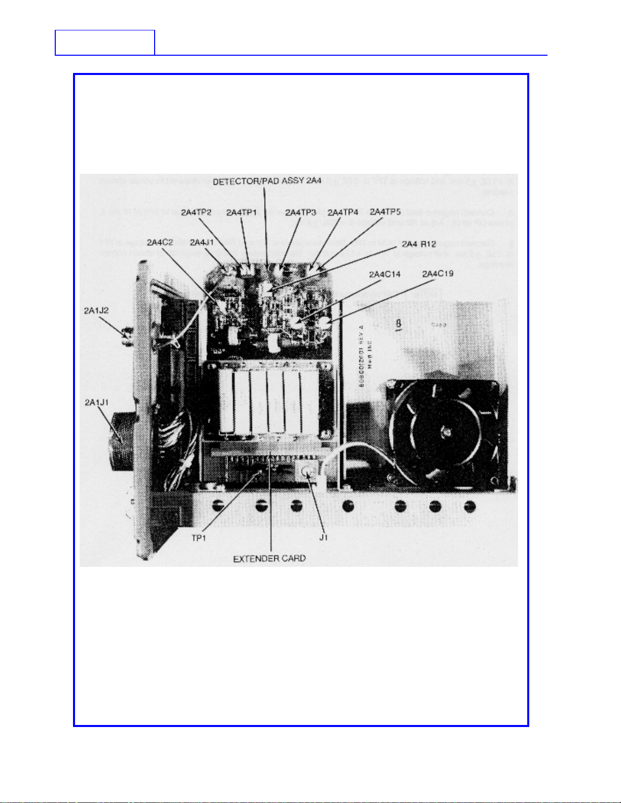
Refer to Figure 5.11.
The Motherboard serves as an interconnection plane between the RF Assembly 2A2, the Computer Board 2A3,
the Detector/Pad Assembly 2A4 and the coupler front panel. Transistor Q1 grounds the TUNING line during
a coupler tune sequence. U1 is the primary +5 VDC regulator supplying power to the Computer Board 2A3.
It is mounted on the coupler sheet metal chassis for heat sinking, and plugs into the motherboard. Figure 5.10
shows the Front Panel wiring diagram.
4-11

SUNAIR CU-9125
THIS PAGE INTENTIONALLY LEFT BLANK.
4-12

SUNAIR CU-9125
SECTION V
ALIGNMENT
GENERAL
5.1
This section provides test procedures and evaluation of overall performance for the CU-9125 Automatic Digital
Antenna Coupler. A Fault Analysis Table is included to aid the repairman in isolating a fault to the defective module
or subassembly.
5.2 PREVENTIVE MAINTENANCE
Reduce the effects of salt air and salt water to the front panel and case of the CU-9125.
When CU-9125 Coupler is installed in a harsh environment (i.e. salt air/salt water), the following preventive
maintenance procedures should be accomplished:
1. The complete outside of the coupler unit should be washed with fresh water every two (2) weeks.
2. Once a year open the coupler unit and remove the old gasket. Clean the metal surface and groove in
the front panel. Clean the metal mating surface on the case. Install a new "O" Ring Gasket P/N 1006320032
into the front panel groove and reassemble coupler unit. See Figure 5.1.
3. Anytime the coupler unit is opened a new "O" Ring Gasket should be installed prior to reassembling the
coupler unit.
5.3 INSPECTION
If the CU-9125 has the case removed for maintenance, a visual inspection should be performed and the resultant
corrective action should be taken as follows:
1. Inspect chassis for loose or missing mounting hardware, deformation, damaged fasteners, or damaged
connectors. Replace all damaged parts.
2. Inspect connectors for broken parts; check insulation for cracks; and check the pins for damage,
misalignment, or bad plating. Carefully realign pins when possible; or, if connectors are otherwise severely
damaged, replace connector. Check for loose, or poorly soldered connections to terminals or connectors.
Tighten or solder as required.
3. Inspect wiring of chassis and subassemblies for any signs of physical damage or charring. Any damaged
wires must be replaced.
4. Inspect for leaky, blistered, charred, or cracked capacitors, resistors, or diodes. Check for loose or
corroded terminal connections. Obviously damaged components should be replaced.
5-1

SUNAIR CU-9125
5. Inspect for cold soldered or resin joints. Bad joints can be recognized by a dull, porous appearance.
Resolder.
6. Antenna coupler cover removal:
a. Remove the 8 Phillips’ head screws.
b. Slide the unit out of the case.
5-2
Figure 5.1 CU-9125 Antenna Coupler Cover Removal.

SUNAIR CU-9125
5.4 REPAIR OR REPLACEMENT
The repair or replacement of damaged and defective parts usually involves standard service techniques.
Carefully examine the equipment to determine the correct technique required to effect the repair.
5.4.1 GENERAL PRECAUTIONS
a) Perform repairs and replace components with power disconnected from unit.
b) Replace connectors, shielded conductors, and twisted pairs only with identical items.
c) Reference to component side of a printed circuit board means the side on which the majority of
components are located; solder or circuit side refers to the other side.
d) When repairing circuits, carefully observe lead dress and component orientation. Keep leads as short
as possible and observe correct repair techniques.
e) Observe cable routing prior to disassembly to enable the proper reinstallation of cabling during
reassembly procedures.
f) If component is defective beyond any reasonable doubt, remove and replace according to the procedures
given in paragraph 5.4.4. If there is some doubt about the condition of a component, or if it is being removed
for troubleshooting, remove it according to the procedures in paragraph 5.4.4.
5.4.2 CIRCUIT CARD ASSEMBLY, TWO-LEAD COMPONENT REMOVAL
(RESISTORS, CAPACITORS, DIODES, ETC.)
a) Inspect solder side of component to determine if the leads were bent over prior to soldering. If they weren’t,
proceed to Step b. If they were, melt the solder and remove it with a desoldering tool, then straighten the leads
and remove the component.
b) Heat one lead from component side of board until solder flows and lift one lead from board; repeat for
other lead and remove component (note orientation).
c ) Melt solder in each hole and using desoldering tool, remove solder from each hole.
d) Dress and form leads of replacement component; insert leads into correct holes.
e) Solder in place and clip leads on solder side of board.
5.4.3 CIRCUIT CARD ASSEMBLY, MULTI-LEAD COMPONENT REMOVAL
(IC’s, etc.)
a) Remove component by clipping each lead along both sides. Clip off leads as close to component as
possible. Discard component.
b) Heat hole from solder side and remove clipped lead from each hole.
c ) Melt solder in each hole and using a desoldering suction tool, remove solder from each hole.
5-3

SUNAIR CU-9125
d) Insert replacement component, observing correct orientation.
e) Solder component in place from solder side of board. Avoid solder runs. No solder is required on contacts
where no track exists.
5.4.4 REMOVAL OF COMPONENTS OF DOUBTFUL CONDITION
a) To remove components that are not heat sensitive melt the solder and remove it with a desoldering tool,
then remove the component.
b) To remove components that are heat sensitive, such as diodes, transistors, and IC’s, connect a heat
sink to the lead between the body of the component and the solder joint, melt and remove the solder. Repeat
for all leads of the component, then remove the component. Apply heat to the lead for the minimum amount
of time necessary to remove the solder. When working with IC’s, start at one corner, then go to the lead farthest
away, then back to where you started, etc....(Example: pins 1, 8, 14, 7,...) This is to keep heat buildup to
a minimum. Remember that some solid state devices are extremely heat sensitive; and even though maximum
care is exercised during their removal, they may still be destroyed by the removal procedure.
c) To install a heat sensitive component, use a heat sink and the sequence outlined above to prevent heat
from destroying the component.
5.5 PERFORMANCE TEST
The following tests will aid in determining specific problems.
5.5.1 TEST EQUIPMENT
The following test equipment or equivalent is required to perform the test procedures outlined in this section.
1. Exciter/Transceiver
2. 35 ft. Whip Antenna Simulator, Model TS-100 Sunair P/N 8084001094
3. ‘THRULINE’ Wattmeter: Bird Model 43 with 100 Watt 2-30 MHz element
4. VOM: Simpson 260 (20k Ohm/Volts)
5. Digital Multimeter: H.P. Model 3476A
6. Oscilloscope: Tektronix 2445
7. Frequency Counter: Systron Donner Model 6242A
8. PC Assy, Detector Extender Board Sunair P/N 8085165091
9. Coaxial Resistor: Bird Model 8135, 50 Ohm, 150 Watt
5-4

SUNAIR CU-9125
5.5.2 PRELIMINARY
Connect Transceiver/Exciter, Antenna Coupler, and Test Equipment as shown in Figure 5.4, Antenna Coupler
Test Set Up.
a) Set the Transceiver/Exciter´s switches and controls to the positions shown below and turn on.
SWITCH OR CONTROL POSITION
‘FREQUENCY’ 1.60000 MHz
‘VOLUME’ Control/On/Off On
‘SQUELCH’ Control Off
b) The Transceiver/Exciter display will alternately display ‘COUPLER UNTUNED’. Depress the ‘CPLR
TUNE’ pushbutton. The Thruline Wattmeter should indicate 30 to 35 Watts of forward RF power while the
coupler is tuning. The Transceiver/Exciter will display ‘COUPLER TUNING’ and then ‘SYSTEM READY’ and
the coupler should be tuned. The Thruline Wattmeter should show no forward RF power after the tune cycle
is completed.
c) Set mode to CW and key the Transceiver/Exciter with CW key switch. Check the forward and reflected
power on the Thruline Wattmeter. An acceptable tune should show 70 to 125 forward Watts and 2.8 to 5.1
reflected Watts maximum. See chart below:
FORWARD WATTS REFLECTED WATTS MAXIMUM
70 2.8
80 3.2
100 4.0
110 4.4
125 5.1
Acceptable Reflected Power Chart for VSWR 1.5:1.
d) Set the Transceiver/Exciter to the following frequencies and tune the coupler. Using the CW key switch
check the forward and reflected power of each frequency to see if they fall within the parameters given in the
preceding paragraph.
1.9900 MHz 4.6000 MHz 12.6000 MHz
2.6000 MHz 6.6000 MHz 25.6000 MHz
3.6000 MHz 9.6000 MHz 29.9900 MHz
NOTE: If upon completion of the Performance Test Procedures, the CU-9125
is not operating properly, accomplish the following alignment
procedures. Remove Antenna Coupler from case, see Figure 5.1.
5-5

SUNAIR CU-9125
Figure 5.2 CU-9125, Computer Board Test Points and Adjustment Locations.
5.5.3 CU-9125, ALIGNMENT PROCEDURE for COMPUTER BOARD ASSEMBLY (2A3)
NOTE: All measurements and adjustments are accomplished on the Computer
Board (2A3). (See Figure 5.2).
a) Turn on the Exciter/Transceiver. (It is necessary to supply power to the coupler).
b) Connect negative lead of DVM to ground. Set meter scale to read +10 VDC.
c ) Measure voltage at TP1 (U22 pin 3+10VDC regulator); should read +10.5,
5-6
+.5 VDC.
d) Connect negative lead of DVM to ground. Set meter scale to read +5 VDC.
SUNAIR CU-9125
e) Measure voltage at TP2 (junction of voltage divider R28 and R29) should read +5.25,
f) Measure voltage at TP3 (U19 pin 4, VSWR OP amp). Adjust R43 until voltage is +1.75,
g) Connect negative lead of DVM to TP7 (U18 pin 11 magnitude OP amp). Set meter scale to read 200 mv.
Connect positive lead to TP6 (U18 pin 8 magnitude OP amp). Adjust R19 until voltage is +224,
h) Connect negative lead of DVM to TP2. Measure voltage at TP6 and TP7. Adjust R66 until voltage at
TP6 is +112,
reading.
i) Connect negative lead of DVM to TP5 (U18 pin 7, phase OP amp) and positive lead to TP4 (U18 pin 4,
phase OP amp). Adjust R6 until voltage is +224,
j) Connect negative lead of DVM to TP2. Measure voltage at TP5 and TP4. Adjust R61 until voltage at
TP5 is -112,
readings.
+5 mv, and voltage at TP7 is -112, +5 mv. Repeat steps g) and h) as required to obtain correct
+5 mv.
+5 mv, and voltage at TP4 is +112, +5 mv. Repeat steps i) and j) as required to obtain correct
NOTE: This completes the alignment of the Computer Board Assembly.
+.5 VDC.
+.05 VDC.
+5 mv.
5-7
SUNAIR CU-9125
Figure 5.3 CU-9125 Detector/Pad (2A4) and Extender Card Test Points and Adjustment Locations.
5-8

SUNAIR CU-9125
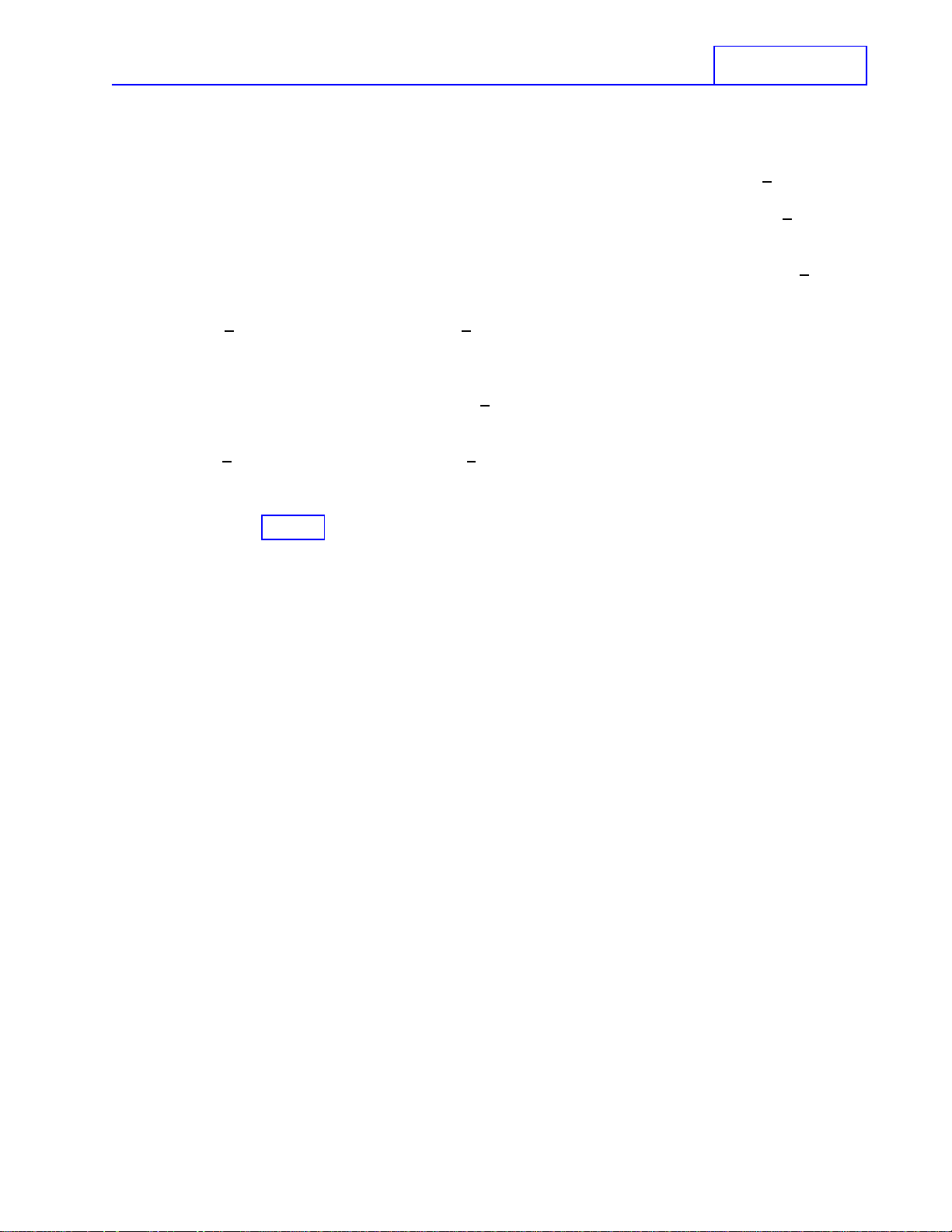
5.5.4 ALIGNMENT PROCEDURE for DETECTOR/RELAY PAD ASSEMBLY (2A4)
Connect Transceiver/Exciter, Antenna Coupler and Test Equipment as shown in Figure 5.4 Detector/Relay
Pad Alignment Set Up. Install Detector/Relay Pad Assembly (2A4) on card extender (Sunair P/N 8085165091).
(See Figure 5.3).
NOTE: All measurements and adjustments are accomplished on the 2A4
board. See Figure 5.3 for Test Point and Adjustment Locations.
a) Turn on Transceiver/Exciter (it is necessary to supply power to the coupler). Set Transceiver/Exciter
frequency to 29.6050 MHz and select ‘AM’ mode.
b) Key the Transceiver/Exciter with the microphone PTT key switch. Power shown on Thruline Wattmeter
connected to Transceiver/Exciter output will display 40 to 50 Watts. Thruline Wattmeter connected to J1 on
Detector/Relay Pad extender card output will display 40 to 50 Watts. Ground TP1 on extender card,
Transceiver/Exciter output should still display 40 to 50 Watts, but extender card output should drop to 10 to
12 Watts. This verifies that the 6 dB pad is operating. Example: 40 Watts without the pad divided by 4 equals
10 Watts with the pad energized. Unkey the Transceiver/Exciter and remove the ground from TP1.
c) Connect common lead of DVM to ground. Connect positive lead of DVM to TP4 (Reflected Power). Key
the Transceiver/Exciter with the microphone PTT key switch. AM power of 40 to 50 Watts will now be displayed
on the two (2) Wattmeters. The DVM will display a positive voltage. Adjust C14 for .000 to +.050 VDC
reading on DVM. Momentarily disconnect coax cable to the 50 Ohm load. Observe on DVM a positive change
to 3.0 VDC or higher. If not, detector is not working and needs troubleshooting and repair. Reconnect cable
to load. DVM should return to adjusted reading, unkey Transceiver/Exciter.
d) Connect common lead of DVM to TP2 (+5 VDC Reference) and connect positive lead to TP1 (Magnitude
Detector). Key Transceiver/Exciter with microphone PTT key switch. AM power of 40 to 50 Watts will be
displayed on the two (2) Wattmeters. Adjust C2 for .000 to .050 VDC reading on DVM. Momentarily disconnect
coax cable to the 50 Ohm load. Observe DVM, a change should be seen. If not, the detector is not working
and should be troubleshot and repaired. Reconnect cable to load. DVM will return to adjusted reading, unkey
Transceiver/Exciter.
e) Leave common lead of DVM connected to TP2 (+5 VDC Reference) and move positive lead to TP3 (Phase
Detector). Key Transceiver/Exciter with microphone PTT key switch. AM power of 40 to 50 Watts will be
displayed on the two (2) Wattmeters. Note the DVM reading at 29.90000 MHz. Step in MHz increments to
1.60500 MHz, noting the DVM reading at each step, to get the maximum positive and negative voltage reading.
Adjust R12 as needed until maximum positive and negative voltage at TP3 are equal and the magnitude of
the voltage does not exceed .050 VDC. Momentarily disconnect coax cable to 50 Ohm load. A change in
the DVM reading should be seen. If not, detector is not working and needs troubleshooting and repair.
Reconnect cable to load. DVM should return to adjusted reading, unkey Transceiver/Exciter.
f) Reverse coax cable connections at 2A1J2 and J1 on extender card; this will send the RF in reverse through
2A4 circuitry. Connect common lead of DVM to ground and connect positive lead to TP5 (RF Detector FWD).
Key the Transceiver/Exciter with microphone PTT key switch. AM power of 40 to 50 Watts will be shown on the
two (2) Thruline Wattmeters. The DVM will display a positive voltage. Adjust C19 for .000 to +.050 VDC.
Momentarily disconnect coax cable to 50 Ohm load. Observe on DVM a positive change to 2.0 VDC or higher.
If not, detector is not working and needs troubleshooting and repair. Reconnect cable to load. DVM will return
to adjusted reading, unkey Transceiver/Exciter and turn off. Remove card extender and reinstall 2A4.
NOTE: This completes the alignments for the Computer Board (2A3)
and the Detector/Relay Pad (2A4). Re-perform the Tests
outlined in Section 5.5.2, Antenna Coupler Performance Test.
If Antenna Coupler still fails the tests in Section 5.5.2, go to
Tables 5.1 and 5.2, isolate and repair the problem.
5-9

SUNAIR CU-9125
5-10
DETECTOR/RELAY PAD ALIGNMENT SET UP
Figure 5.4 Coupler Test.

SYMPTOM
T able 5.1 Fault Analysis.
POSSIBLE TROUBLE
SUNAIR CU-9125
CHECKS AND
CORRECTIVE ACTION
No meter readings in FWD or REF
position, coupler faults 10 seconds
after CPLR TUNE command.
Meter reads normally in FWD
position. No reading in REF position.
Coupler faults 10 seconds after
CPLR TUNE command.
Meter reads normally in both FWD
and REF positions. Coupler faults
10 seconds after CPLR TUNE
command.
Coupler tunes normally, but faults
when 125 W is applied.
a. No RF output from 9000 Series
Exciter/Transceiver.
a. No RF to coupler.
b. Coupler Detector Board 2A4,
defective.
a. Computer Board 2A3, defective.
b. Defective component on RF
Assembly 2A2.
a. VSWR trip point set too low.
a. Defective Exciter/Transceiver.
b. Defective Detector Assy, 2A4.
Align, repair or replace.
a. Check coax cable and connectors
between exciter/transceiver and
coupler. Meter in REF position
should read greater than zero during
TUNE, dipping to a low value when
coupler TUNE is achieved.
b. Align, repair or replace.
a. Align, repair or replace Computer
Board 2A3.
b. Check components for damage
and/or severe discoloration.
Replace as required.
a. If fault condition is noted on more
than just a very few frequencies,
check voltage on Computer Board
2A3 test point TP3 to ground. Voltage
should be 1.7 VDC minimum. Adjust
VSWR control 2A3R43 to increase
voltage reading to 1.72 VDC or to a
value approximately 0.1 VDC higher
than measured.
b. Internal high voltage
breakdown.
c. Loose antenna or ground
connection, or corrosion.
d. Defective internal ground
connection.
b. Observe coupler tune in darkened
area and look for breakdown on
Output Board 2A2A4 or Inductor
Board 2A2A3. Repair or replace
defective component.
c. Check antenna and ground
connections for tightness and
freedom from corrosion.
d. (1) Check all Motherboard 2A1A1
and RF Assembly 2A2 ground
screws for tightness.
(2) Check Computer Board 2A3
connectors for clean connector
contacts. Clean or replace.
5-11

SUNAIR CU-9125
5-12
Figure 5.5 Major Assembly and Component Locations (Front View).

SUNAIR CU-9125
Figure 5.6 Major Assembly and Component Locations (Top View).
5-13
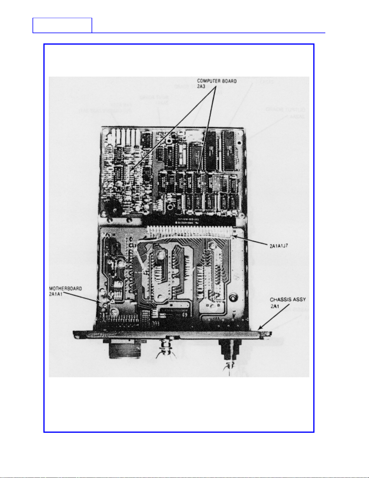
SUNAIR CU-9125
5-14
BOTTOM VIEW
Figure 5.7 Major Assembly and Component Locations (Bottom View).
SUNAIR CU-9125
Figure 5.8 Major Assembly and Component Locations (Right Side View).
5-15

SUNAIR CU-9125
5-16
LEFT SIDE VIEW
Figure 5.9 Major Assembly and Component Locations (Left Side View).

SUNAIR CU-9125
Figure 5.10 Front Panel Wiring Diagram.
5-17

SUNAIR CU-9125
THIS PAGE INTENTIONALLY LEFT BLANK.
5-18

SUNAIR CU-9125
T able 5.2 F AUL T ANAL YSIS AND TROUBLESHOOTING,
COMPUTER BOARD (2A3)
(Refer to Figure 5.16)
NOTE: For this test procedure, a 35 ft. whip antenna simulator is required.
An equivalent type of simulator may be used or one may be
purchased from Sunair (P/N 8084001094) or built from the
schematic diagram in Figure 5.18.
Equipment necessary for preliminary setup will include the following:
a) Test equipment: Frequency/waveform monitor, Figure 5.4 and a Digital Voltmeter (DVM).
b) Exciter/Transceiver: AM mode of operation.
c ) Connect 35 ft. whip antenna simulator to antenna terminal on the coupler unit.
When instructed to change Exciter/Transceiver frequency, change frequency by no less than 2 MHz.
CIRCUIT UNDER TEST
1) +28 VDC supply.
2) +5 VDC supply.
3) 1 MHz clock oscillator.
INSTRUCTIONS
a) Connect negative lead of DVM to
chassis and positive lead to Mother
board connector 2A1A1 J7, pin 27.
(See Figure 5.11)
a) Connect positive lead of DVM to
Mother board connector 2A1A1
VR1 pin 2. (See Figure 5.11)
a) Connect oscilloscope probe to
U1, pin 1.
RESULT/ACTION
NORMAL: DVM indicates +28 V +4
VDC.
ABNORMAL: Unplug Computer
board. If DVM reads the specified
voltage, check for shorts on the
board. If still reading wrong voltage,
check control cable. Check for
shorts on the RF Assembly, 2A2.
NORMAL: DVM indicates +5 V
+.5 VDC.
ABNORMAL: Unplug Computer
board. If DVM reads the specified
voltage, check for shorts on the
board. If it still reads the wrong
voltage, replace the 5 V regulator
(U1), mounted on the chassis
assembly 2A1.
NORMAL: Frequency = 1 MHz
square wave, 4 V p-p minimum.
ABNORMAL: Replace U23.
4) TUNE command circuit.
a) Connect scope probe to CR2
anode. Depress ‘CPLR TUNE’
pushbutton on the Exciter/
Transceiver.
NORMAL: Scope indicates a
momentary 0 VDC to +10 VDC low
to high change. Coupler tunes.
ABNORMAL: Check Mother board.
Check control cable between radio
and coupler. Check Exciter/
Transceiver for proper inputs to
coupler.
5-19

SUNAIR CU-9125
T able 5.2 F AUL T ANAL YSIS AND TROUBLESHOOTING,
COMPUTER BOARD (2A3)
CIRCUIT UNDER TEST
CONTINUED...
(Refer to Figure 5.16)
INSTRUCTIONS
b) Connect scope probe to Q1 base.
Depress ‘CPLR TUNE’ pushbutton
on Exciter/Transceiver.
c) Connect scope probe to Q1
collector. Depress ‘CPLR TUNE’
pushbutton on Exciter/Transceiver.
d) Connect scope probe to U5, pin
5. Depress ‘CPLR TUNE’
pushbutton on Exciter/Transceiver.
RESULT/ACTION
NORMAL: Scope indicates a +1
VDC level at Q1 base. This level
remains until coupler has tuned,
then indicates 0.5 V.
ABNORMAL: Check Q1 and
associated circuitry.
NORMAL: Scope indicates a
voltage level of 0 VDC at Q1 collector
while tuning. Level should remain
low until coupler has completed the
tune cycle. Scope now indicates a
+24 VDC level.
ABNORMAL: Repair or replace Q1
or associated circuitry. Check
Mother board 2A1A1. Check Tune
Relay on Detector board, assembly
2A4. Refer to Section 4.3.6.
NORMAL: Scope indicates
momentary 0 V to +5 VDC pulse.
Coupler tunes.
ABNORMAL: Check C16, C17,
C23, L4, R34, CR17, R35 and U5.
Repair or replace.
5) +10 VDC supply.
6) Detector reference.
5-20
e) Connect scope probe to U1, pin
8. Depress ‘CPLR TUNE’
pushbutton on Exciter/Transceiver.
a) Connect DVM negative lead to
ground (chassis) and connect
positive lead to TP1.
a) Connect DVM negative lead to
ground (chassis) and connect
positive lead to TP2.
NORMAL: Scope indicates
momentary 0 V to +5 VDC pulse.
Coupler tunes.
ABNORMAL: Check U27A, U27B
and repair or replace.
NORMAL: DVM indicates a reading
of approximately 10.5 V, +.5 VDC.
ABNORMAL: If voltage is off by
more than .5 VDC, check U22
circuitry for defective component.
NORMAL: DVM indicates a reading
of 5 V, +0.05 VDC.
ABNORMAL: If proper voltage is
not present, check divider resistors
R28 and R29.

SUNAIR CU-9125
T able 5.2 F AUL T ANAL YSIS AND TROUBLESHOOTING,
COMPUTER BOARD (2A3)
CIRCUIT UNDER TEST
7) Phase and magnitude
comparators.
CONTINUED...
(Refer to Figure 5.16)
INSTRUCTIONS
a) Connect scope probe to U17, pin
12. Change frequency of Exciter/
Transceiver and depress
microphone key.
b) Connect scope probe to U17, pin
10. Change frequency of Exciter/
Transceiver and depress
microphone key.
RESULT/ACTION
NORMAL: Scope indicates a
varying voltage of 3 to 5 V of
approximately 2 V p-p. This
continues until the tune cycle is
complete.
ABNORMAL: Check circuitry
related to U17 and check Detector/
Pad Assembly 2A4. Refer to
Sections 4.3 and 5.5.4.
NORMAL: Scope indicates a
varying voltage of 3 to 5 V of
approximately 2 V p-p. This
continues until the tune cycle is
complete.
ABNORMAL: Check circuitry
related to U17 and check Detector/
Pad Assembly 2A4. Refer to
Sections 4.3 and 5.5.4.
c) Connect scope probe to U18, pin
2. Change frequency of Exciter/
Transceiver and depress
microphone key.
d) Connect scope probe to U18, pin
1. Change frequency of Exciter/
Transceiver and depress
microphone key.
NORMAL: Scope indicates pulses
between 0 V and +10 V during the
tune cycle.
ABNORMAL: Check U18 and
associated circuitry. Check
Detector/Pad Assembly 2A4. See
Sections 4.3 and 5.5.4. Check set
up of phase and magnitude windows
according to Section 5.5.3.
NORMAL: Scope indicates pulses
between 0 V and +10 V during the
tune cycle.
ABNORMAL: Check U18 and
associated circuitry. Check
Detector/Pad Assembly 2A4. See
Sections 4.3 and 5.5.4. Check set
up of phase and magnitude windows
according to Section 5.5.3.
5-21

SUNAIR CU-9125
T able 5.2 F AUL T ANAL YSIS AND TROUBLESHOOTING,
COMPUTER BOARD (2A3)
CIRCUIT UNDER TEST
CONTINUED...
(Refer to Figure 5.16)
INSTRUCTIONS
e) Connect scope probe to U18, pin
14. Change frequency of Exciter/
Transceiver and depress
microphone key.
f) Connect scope probe to U18, pin
13. Change frequency of Exciter/
Transceiver and depress
microphone key.
RESULT/ACTION
NORMAL: Scope indicates pulses
between 0 V and +10 V during the
tune cycle.
ABNORMAL: Check U18 and
associated circuitry. Check
Detector/Pad Assembly 2A4. See
Sections 4.3 and 5.5.4. Check set
up of phase and magnitude windows
according to Section 5.5.3.
NORMAL: Scope indicates pulses
between 0 V and +10 V during the
tune cycle.
ABNORMAL: Check U18 and
associated circuitry. Check
Detector/Pad Assembly 2A4. See
Sections 4.3 and 5.5.4. Check set
up of phase and magnitude windows
according to Section 5.5.3.
8) Reflected power.
g) Connect scope probe to U20, pin
2. Change frequency of Exciter/
Transceiver and depress
microphone key.
h) Repeat checks on U20, pins 4, 6,
and 8. Change frequency of Exciter/
Transceiver and depress
microphone key.
a) Connect scope probe to U19, pin
1. Change frequency of Exciter/
Transceiver and depress the
‘CPLR TUNE’ pushbutton on
Exciter/Transceiver.
NORMAL: Scope indicates pulses
of 0 V to +5 V p-p.
ABNORMAL: Check related
circuitry. Check Detector/Pad
Assembly 2A4. See Sections 4.3
and 5.5.4.
NORMAL: Scope indicates pulses
of 0 V to +5 V p-p.
ABNORMAL: Check related
circuitry. Check Detector/Pad
Assembly 2A4. See Sections 4.3
and 5.5.4.
NORMAL: Scope indicates a
varying 2 V p-p voltage. Nulling
occurs when tune is complete.
ABNORMAL: Check U19 and
associated circuitry. Check
Detector/Pad Assembly 2A4. See
Sections 4.3 and 5.5.4.
5-22

SUNAIR CU-9125
T able 5.2 F AUL T ANAL YSIS AND TROUBLESHOOTING,
COMPUTER BOARD (2A3)
(Refer to Figure 5.16)
CIRCUIT UNDER TEST INSTRUCTIONS
b) Connect scope probe to U19, pin
2. Change frequency of Exciter/
Transceiver and depress
microphone key.
c) Connect scope probe to U20, pin
10. Change frequency of Exciter/
Transceiver and depress
microphone key.
d) Connect scope probe to U1, pin
9. Change frequency of Exciter/
Transceiver and depress
microphone key.
CONTINUED...
RESULT/ACTION
NORMAL: Scope indicates a high
during the tune cycle, and a low at
the completion of the tune.
ABNORMAL: Check U19 and
associated circuitry. Check
Detector/Pad Assembly 2A4. See
Sections 4.3 and 5.5.4.
NORMAL: Scope indicates a low
during the tune cycle, and a high at
the completion of the tune.
ABNORMAL: Check U20 and
associated circuitry. Check
Detector/Pad Assembly 2A4. See
Sections 4.3 and 5.5.4.
NORMAL: Scope indicates a high
during the tune cycle and a low at the
completion of the tune.
ABNORMAL: Check U19C, U24F,
U27C, U27D, U1, and associated
circuitry. Check Detector/Pad
Assembly 2A4. See Sections 4.3
and 5.5.4.
9) RF detector (forward power
detector).
10) RF
a) Connect scope probe to TP3.
Change frequency of Exciter/
Transceiver and depress
microphone key.
a) Connect scope probe to collector
of Q2. Depress the ‘CPLR TUNE’
pushbutton on the Exciter/
Transceiver.
NORMAL: Scope indicates varying
voltage until the end of tune cycle.
Then indicates approximately +1.75
VDC.
ABNORMAL: Check U19 and
associated circuitry. Check
Detector/Pad Assembly 2A4. See
Sections 4.3 and 5.5.4.
NORMAL: The scope indicates a
low during the tune cycle, and a high
at the completion of the tune.
ABNORMAL: Check Q2 and
associated circuitry. Check Forward
Power Detector on Detector/Pad
Assembly 2A4. See Sections 4.3
and 5.5.4.
5-23

SUNAIR CU-9125
T able 5.2 F AUL T ANAL YSIS AND TROUBLESHOOTING,
CIRCUIT UNDER TEST
11) ‘FAULT’ circuit.
12) ‘READY’ circuit.
COMPUTER BOARD (2A3)
(Refer to Figure 5.16)
INSTRUCTIONS
a) Connect scope probe to U6, pin
16. Turn the Exciter/ Transceiver’s
power off. Wait approximately 4
seconds and turn power back on.
b) Connect scope probe to U11, pin
12. Turn the Exciter/ Transceiver’s
power off. Wait approximately 4
seconds and turn power back on.
a) Connect scope probe to U6, pin
15. Depress the ‘CPLR TUNE’
pushbutton on the Exciter/
Transceiver.
b) Connect scope probe to U11, pin
13.
CONTINUED...
RESULT/ACTION
NORMAL: Scope will show a +5
VDC level indication when Exciter/
Transceiver is turned back on. For
further information on the function of
the output ports, see Section 4.4.9.7.
ABNORMAL: Check U6 and
associated circuitry. Check control
cable between coupler and Exciter/
Transceiver.
NORMAL: Scope will indicate a low
voltage when the radio is turned
back on.
ABNORMAL: Check U11 and
associated circuitry. Check control
cable between coupler and Exciter/
Transceiver.
NORMAL: Scope indicates a high
when tune cycle is complete. For
further information on the function of
the output ports, see Section 4.4.9.7.
ABNORMAL: Check U6 and
associated circuitry. Check control
cable between coupler and Exciter/
Transceiver.
13) Pad relay.
5-24
a) Connect scope probe to U6, pin
19. Depress the ‘CPLR TUNE’
pushbutton on the Exciter/
Transceiver.
b) Connect scope probe to U11, pin
11. Depress the ‘CPLR TUNE’
NORMAL: Scope indicates a low.
ABNORMAL: Check associated
circuitry of U11. Check control
cable between coupler and Exciter/
Transceiver.
NORMAL: Scope indicates a high
during the tune cycle, and a low at
the completion of the tune cycle.
ABNORMAL: Check U6 and related
circuitry. For further information on
the function of the output ports,
see Section 4.4.9.7.
NORMAL: Scope indicates a low
during the tune cycle, and

SUNAIR CU-9125
T able 5.2 F AUL T ANAL YSIS AND TROUBLESHOOTING,
COMPUTER BOARD (2A3)
(Refer to Figure 5.16)
CIRCUIT UNDER TEST INSTRUCTIONS RESULT/ACTION
pushbutton on the Exciter/
Transceiver.
a) Connect scope probe to U5, pin
21. Remove 35 ft. whip antenna
14) NETWORK RELAY DRIVERS:
14a) C17.
simulator. Short antenna terminal
to ground terminal with a 3 ft. clip
lead. (Short antenna terminal ONLY
for the testing of 14a.a. NOT for any
of the following like tests). Place
exciter/transceiver in the ‘AM’ mode,
at 1.6000 MHz. Depress the
microphone key.
b) Reconnect Antenna simulator
and connect scope probe to U9, pin
CONTINUED...
approximately +28 V level at the
completion of tune.
ABNORMAL: Check U11 and
related circuitry. For further
information on the function of the
output ports see Section 4.4.9.7.
Also check K1 and related circuitry
on Detector board (2A4A1).
NORMAL: Scope indicates a +3
V p-p, + change. If the tune cycle
ends and the pulse did not occur,
change the frequency of the Exciter/
Transceiver by 100 kHz and repeat.
Perform this procedure 6
times.
ABNORMAL: If after 6 times the
scope does not change, check U5
and related circuitry. For further
information on the function of the
output ports, see Section 4.4.9.7.
16. Place exciter/transceiver in the
‘AM’ mode, at 1.6000 MHz. Depress
the microphone key.
a) Connect scope probe to U5, pin
25. Place Exciter/Transceiver in
NORMAL: Scope indicates a
+28 V p-p, + change. If the +28 V
change does not occur, change the
frequency of the Exciter/Transceiver
by 100 kHz and repeat. Perform this
procedure 6 times.
ABNORMAL: If after 6 times the
scope does not change, check U9
and related circuitry. For further
information on the function of the
output ports, see Section 4.4.9.7.
Also check relay K28 and related
circuitry on Output board (2A2A4).
NORMAL: Scope indicates a +3
V p-p change. If tune cycle ends and
5-25

SUNAIR CU-9125
T able 5.2 F AUL T ANAL YSIS AND TROUBLESHOOTING,
COMPUTER BOARD (2A3)
(Refer to Figure 5.16)
INSTRUCTIONSCIRCUIT UNDER TEST
14b) C13. the ‘AM’ mode, at 1.6000 MHz.
Depress the microphone key.
b) Connect scope probe to U9, pin
15. Place Exciter/Transceiver in
the ‘AM’ mode, at 1.7000 MHz.
Depress the microphone key.
a) Connect scope probe to U5, pin
26. Place Exciter/Transceiver in
CONTINUED...
RESULT/ACTION
the pulse did not occur change the
frequency on the Exciter/Transciver
by 100 kHz and repeat. Perform this
procedure 6 times.
ABNORMAL: If after 6 times the
scope does not change, check U5
and related circuitry. For further
information on the function of the
output ports, see Section 4.4.9.7.
NORMAL: Scope indicates a
+28 V p-p, + change. If the +28 V
change does not occur, change the
frequency of the Exciter/Transceiver
by 100 kHz and repeat. Perform this
procedure 6 times.
ABNORMAL: If after 6 times the
scope does not change, check U9
and related circuitry. For further
information on the function of the
output ports, see Section 4.4.9.7.
Also check relay K24 and related
circuitry on Output board (2A2A4).
14c) C14.
the ‘AM’ mode, at 1.6000 MHz.
Depress the microphone key.
b) Connect scope probe to U9, pin
14. Place Exciter/Transceiver in
NORMAL: Scope indicates a +3
V p-p change. If tune cycle ends and
the pulse did not occur change the
frequency on the Exciter/
Transceiver by 100 kHz and repeat.
Perform this procedure 6 times.
ABNORMAL: If after 6 times the
scope does not change, check U5
and related circuitry. For further
information on the function of the
output ports, see Section 4.4.9.7.
NORMAL: Scope indicates a
+28 V p-p, + change. If the +28 V
5-26

SUNAIR CU-9125
T able 5.2 F AUL T ANAL YSIS AND TROUBLESHOOTING,
COMPUTER BOARD (2A3)
(Refer to Figure 5.16)
CIRCUIT UNDER TEST INSTRUCTIONS RESULT/ACTION
the ‘AM’ mode, at 1.7000 MHz.
Depress the microphone key.
a) Connect scope probe to U5, pin
27. Place Exciter/Transceiver in
14d) C15.
the ‘AM’ mode, at 1.6000 MHz.
Depress the microphone key.
b) Connect scope probe to U9,
pin 13. Place Exciter/Transceiver
CONTINUED...
change does not occur, change the
frequency of the Exciter/Transceiver
by 100 kHz and repeat. Perform this
procedure 6 times.
ABNORMAL: If after 6 times the
scope does not change, check U9
and related circuitry. For further
information on the function of the
output ports, see Section 4.4.9.7.
Also check relay K25 and related
circuitry on Output board (2A2A4).
NORMAL: Scope indicates a
+3 V p-p change. If tune cycle ends
and the pulse did not occur change
the frequency on the Exciter/
Transceiver by 100 kHz and repeat.
Perform this procedure 6 times.
ABNORMAL: If after 6 times the
scope does not change, check U5
and related circuitry. For further
information on the function of the
output ports, see Section 4.4.9.7.
in the ‘AM’ mode, at 1.7000 MHz.
Depress the microphone key.
a) Connect scope probe to U5, pin
28. Place Exciter/Transceiver in
NORMAL: Scope indicates a
+28 V p-p, + change. If the +28 V
change does not occur, change the
frequency of the Exciter/Transceiver
by 100 kHz and repeat. Perform this
procedure 6 times.
ABNORMAL: If after 6 times the
scope does not change, check U9
and related circuitry. For further
information on the function of the
output ports, see Section 4.4.9.7.
Also check relay K26 and related
circuitry on Output board (2A2A4).
NORMAL: Scope indicates a +3
V p-p change. If tune cycle ends and
5-27

SUNAIR CU-9125
T able 5.2 F AUL T ANAL YSIS AND TROUBLESHOOTING,
COMPUTER BOARD (2A3)
(Refer to Figure 5.16)
CIRCUIT UNDER TEST INSTRUCTIONS RESULT/ACTION
14e) C16. the ‘AM’ mode, at 1.6000 MHz.
Depress the microphone key.
b) Connect scope probe to U9, pin
12. Place exciter/transceiver in the
‘AM’ mode, at 1.7000 MHz. Depress
the microphone key.
a) Connect scope probe to U5,
pin 29. Place Exciter/Transceiver
CONTINUED...
the pulse did not occur change the
frequency on the Exciter/
Transceiver by 100 kHz and repeat.
Perform this procedure 6 times.
ABNORMAL: If after 6 times the
scope does not change, check U5
and related circuitry. For further
information on the function of the
output ports, see Section 4.4.9.7.
NORMAL: Scope indicates a
+28 V p-p, + change. If the +28 V
change does not occur, change the
frequency of the Exciter/Transceiver
by 100 kHz and repeat. Perform this
procedure 6 times.
ABNORMAL: If after 6 times the
scope does not change, check U9
and related circuitry. For further
information on the function of the
output ports, see Section 4.4.9.7.
Also check relay K27, K29 and
related circuitry on Output board
(2A2A4).
14f) C1.
5-28
in the ‘AM’ mode, at 1.6000 MHz.
Depress the microphone key.
b) Connect scope probe to U9,
pin 11. Place Exciter/Transceiver
NORMAL: Scope indicates a +3
V p-p change. If tune cycle ends and
the pulse did not occur change the
frequency on the Exciter/
Transceiver by 100 kHz and repeat.
Perform this procedure 6 times.
ABNORMAL: If after 6 times the
scope does not change, check U5
and related circuitry. For further
information on the function of the
output ports, see Section 4.4.9.7.
NORMAL: Scope indicates a

SUNAIR CU-9125
T able 5.2 F AUL T ANAL YSIS AND TROUBLESHOOTING,
COMPUTER BOARD (2A3)
(Refer to Figure 5.16)
CIRCUIT UNDER TEST INSTRUCTIONS
in the ‘AM’ mode, at 1.7000 MHz.
Depress the microphone key.
a) Connect scope probe to U5,
pin 30. Place Exciter/Transceiver
14g) C2.
in the ‘AM’ mode, at 1.6000 MHz.
Depress the microphone key.
b) Connect scope probe to U9,
pin 10. Place Exciter/Transceiver
CONTINUED...
+28 V p-p,
change does not occur, change the
frequency of the Exciter/Transceiver
by 100 kHz and repeat. Perform this
procedure 6 times.
ABNORMAL: If after 6 times the
scope does not change, check U9
and related circuitry. For further
information on the function of the
output ports, see Section 4.4.9.7.
Also check relay K11 and related
circuitry on Intermediate board
(2A2A2).
NORMAL: Scope indicates a +3
V p-p change. If tune cycle ends and
the pulse did not occur change the
frequency on the Exciter/
Transceiver by 100 kHz and repeat.
Perform this procedure 6 times.
ABNORMAL: If after 6 times the
scope does not change, check U5
and related circuitry. For further
information on the function of the
output ports, see Section 4.4.9.7.
RESULT/ACTION
+ change. If the +28 V
in the ‘AM’ mode, at 1.7000 MHz.
Depress the microphone key.
a) Connect scope probe to U5, pin
31. Place Exciter/Transceiver in
NORMAL: Scope indicates a
+28 V p-p, + change. If the +28 V
change does not occur, change the
frequency of the Exciter/Transceiver
by 100 kHz and repeat. Perform this
procedure 6 times.
ABNORMAL: If after 6 times the
scope does not change, check U9
and related circuitry. For further
information on the function of the
output ports, see Section 4.4.9.7.
Also check relay K10 and related
circuitry on Input board (2A2A1).
NORMAL: Scope indicates a +3
5-29

SUNAIR CU-9125
T able 5.2 F AUL T ANAL YSIS AND TROUBLESHOOTING,
CIRCUIT UNDER TEST
14h) C3.
COMPUTER BOARD (2A3)
(Refer to Figure 5.16)
INSTRUCTIONS
the ‘AM’ mode, at 1.6000 MHz.
Depress the microphone key.
b) Connect scope probe to U10, pin
16. Place Exciter/Transceiver in
the ‘AM’ mode, at 1.7000 MHz.
Depress the microphone key.
a) Connect scope probe to U5, pin
32. Place Exciter/Transceiver in
CONTINUED...
V p-p change. If tune cycle ends and
the pulse did not occur change the
frequency on the Exciter/
Transceiver by 100 kHz and repeat.
Perform this procedure 6 times.
ABNORMAL: If after 6 times the
scope does not change, check U5
and related circuitry. For further
information on the function of the
output ports, see Section 4.4.9.7.
NORMAL: Scope indicates a
+28 V p-p,
change does not occur, change the
frequency of the Exciter/Transceiver
by 100 kHz and repeat. Perform this
procedure 6 times.
ABNORMAL: If after 6 times the
scope does not change, check U10
and related circuitry. For further
information on the function of the
output ports, see Section 4.4.9.7.
Also check relay K9 and related
circuitry on Input board (2A2A1).
RESULT/ACTION
+ change. If the +28 V
14i) C4.
5-30
the ‘AM’ mode, at 1.6000 MHz.
Depress the microphone key.
b) Connect scope probe to U10, pin
15. Place Exciter/Transceiver in
NORMAL: Scope indicates a +3
V p-p change. If tune cycle ends and
the pulse did not occur change the
frequency on the Exciter/
Transceiver by 100 kHz and repeat.
Perform this procedure 6 times.
ABNORMAL: If after 6 times the
scope does not change, check U5
and related circuitry. For further
information on the function of the
output ports, see Section 4.4.9.7.
NORMAL: Scope indicates a

SUNAIR CU-9125
T able 5.2 F AUL T ANAL YSIS AND TROUBLESHOOTING,
COMPUTER BOARD (2A3)
(Refer to Figure 5.16)
CIRCUIT UNDER TEST INSTRUCTIONS RESULT/ACTION
the ‘AM’ mode, at 1.7000 MHz.
Depress the microphone key.
a) Connect scope probe to U5, pin
33. Place Exciter/Transceiver in
14j) C5.
the ‘AM’ mode, at 1.6000 MHz.
Depress the microphone key.
b) Connect scope probe to U10, pin
14. Place Exciter/Transceiver in
CONTINUED...
+28 V p-p,
change does not occur, change the
frequency of the Exciter/Transceiver
by 100 kHz and repeat. Perform this
procedure 6 times.
ABNORMAL: If after 6 times the
scope does not change, check U10
and related circuitry. For further
information on the function of the
output ports, see Section 4.4.9.7.
Also check relay K8 and related
circuitry on Intermediate board
(2A2A2).
NORMAL: Scope indicates a +3
V p-p change. If tune cycle ends and
the pulse did not occur change the
frequency on the Exciter/
Transceiver by 100 kHz and repeat.
Perform this procedure 6 times.
ABNORMAL: If after 6 times the
scope does not change, check U5
and related circuitry. For further
information on the function of the
output ports, see Section 4.4.9.7.
+ change. If the +28 V
the ‘AM’ mode, at 1.7000 MHz.
Depress the microphone key.
a) Connect scope probe to U5, pin
34. Place Exciter/Transceiver in
NORMAL: Scope indicates a
+28 V p-p, + change. If the +28 V
change does not occur, change the
frequency of the Exciter/Transceiver
by 100 kHz and repeat. Perform this
procedure 6 times.
ABNORMAL: If after 6 times the
scope does not change, check U10
and related circuitry. For further
information on the function of the
output ports, see Section 4.4.9.7.
Also check relay K7 and related
circuitry on Input board (2A2A1).
NORMAL: Scope indicates a
5-31

SUNAIR CU-9125
T able 5.2 F AUL T ANAL YSIS AND TROUBLESHOOTING,
COMPUTER BOARD (2A3)
(Refer to Figure 5.16)
CIRCUIT UNDER TEST INSTRUCTIONS RESULT/ACTION
14k) C6. the ‘AM’ mode, at 1.6000 MHz.
Depress the microphone key.
b) Connect scope probe to U10, pin
13. Place Exciter/Transceiver in
the ‘AM’ mode, at 1.7000 MHz.
Depress the microphone key.
a) Connect scope probe to U5, pin
35. Place Exciter/Transceiver in
CONTINUED...
+3 V p-p change. If tune cycle ends
and the pulse did not occur change
the frequency on the Exciter/
Transceiver by 100 kHz and repeat.
Perform this procedure 6 times.
ABNORMAL: If after 6 times the
scope does not change, check U5
and related circuitry. For further
information on the function of the
output ports, see Section 4.4.9.7.
NORMAL: Scope indicates a
+28 V p-p, + change. If the +28 V
change does not occur, change the
frequency of the Exciter/Transceiver
by 100 kHz and repeat. Perform this
procedure 6 times.
ABNORMAL: If after 6 times the
scope does not change, check U10
and related circuitry. For further
information on the function of the
output ports, see Section 4.4.9.7.
Also check relay K6 and related
circuitry on Intermediate board
(2A2A2).
14l) C7.
5-32
the ‘AM’ mode, at 1.6000 MHz.
Depress the microphone key.
b) Connect scope probe to U10, pin
12. Place Exciter/Transceiver in
NORMAL: Scope indicates a
+3 V p-p change. If tune cycle ends
and the pulse did not occur change
the frequency on the Exciter/
Transceiver by 100 kHz and repeat.
Perform this procedure 6 times.
ABNORMAL: If after 6 times the
scope does not change, check U5
and related circuitry. For further
information on the function of the
output ports, see Section 4.4.9.7.
NORMAL: Scope indicates a

SUNAIR CU-9125
T able 5.2 F AUL T ANAL YSIS AND TROUBLESHOOTING,
COMPUTER BOARD (2A3)
(Refer to Figure 5.16)
CIRCUIT UNDER TEST INSTRUCTIONS RESULT/ACTION
the ‘AM’ mode, at 1.7000 MHz.
Depress the microphone key.
a) Connect scope probe to U5, pin
36. Place Exciter/Transceiver in
14m) C8.
the ‘AM’ mode, at 1.6000 MHz.
Depress the microphone key.
b) Connect scope probe to U10, pin
11. Place Exciter/Transceiver in
CONTINUED...
+28 V p-p,
change does not occur, change the
frequency of the Exciter/Transceiver
by 100 kHz and repeat. Perform this
procedure 6 times.
ABNORMAL: If after 6 times the
scope does not change, check U10
and related circuitry. For further
information on the function of the
output ports, see Section 4.4.9.7.
Also check relay K5 and related
circuitry on Intermediate board
(2A2A2).
NORMAL: Scope indicates a
+3 V p-p change. If tune cycle ends
and the pulse did not occur change
the frequency on the Exciter/
Transceiver by 100 kHz and repeat.
Perform this procedure 6 times.
ABNORMAL: If after 6 times the
scope does not change, check U5
and related circuitry. For further
information on the function of the
output ports, see Section 4.4.9.7.
+ change. If the +28 V
the ‘AM’ mode, at 1.7000 MHz.
Depress the microphone key.
a) Connect scope probe to U6, pin
2. Place Exciter/Transceiver in the
NORMAL: Scope indicates a
+28 V p-p,
change does not occur, change the
frequency of the Exciter/Transceiver
by 100 kHz and repeat. Perform this
procedure 6 times.
ABNORMAL: If after 6 times the
scope does not change, check U10
and related circuitry. For further
information on the function of the
output ports, see Section 4.4.9.7.
Also check relay K4 and related
circuitry on Input board (2A2A1).
NORMAL: Scope indicates a +3
+ change. If the +28 V
5-33

SUNAIR CU-9125
T able 5.2 F AUL T ANAL YSIS AND TROUBLESHOOTING,
CIRCUIT UNDER TEST
14n) C9.
COMPUTER BOARD (2A3)
(Refer to Figure 5.16)
INSTRUCTIONS RESULT/ACTION
‘AM’ mode, at 1.6000 MHz. Depress
the microphone key.
b) Connect scope probe to U10, pin
10. Place Exciter/Transceiver in
the ‘AM’ mode, at 1.7000 MHz.
Depress the microphone key.
a) Connect scope probe to U6, pin
5. Place Exciter/Transceiver in the
CONTINUED...
V p-p change. If tune cycle ends and
the pulse did not occur change the
frequency on the Exciter/
Transceiver by 100 kHz and repeat.
Perform this procedure 6 times.
ABNORMAL: If after 6 times the
scope does not change, check U6
and related circuitry. For further
information on the function of the
output ports, see Section 4.4.9.7.
NORMAL: Scope indicates a
+28 V p-p, + change. If the +28 V
change does not occur, change the
frequency of the Exciter/Transceiver
by 100 kHz and repeat. Perform this
procedure 6 times.
ABNORMAL: If after 6 times the
scope does not change, check U10
and related circuitry. For further
information on the function of the
output ports, see Section 4.4.9.7.
Also check relay K3 and related
circuitry on Input board (2A2A1).
14o) C10.
5-34
‘AM’ mode, at 1.6000 MHz. Depress
the microphone key.
b) Connect scope probe to U11, pin
16. Place Exciter/Transceiver in
NORMAL: Scope indicates a +3
V p-p change. If tune cycle ends and
the pulse did not occur change the
frequency on the Exciter/
Transceiver by 100 kHz and repeat.
Perform this procedure 6 times.
ABNORMAL: If after 6 times the
scope does not change, check U6
and related circuitry. For further
information on the function of the
output ports, see Section 4.4.9.7.
NORMAL: Scope indicates a

SUNAIR CU-9125
T able 5.2 F AUL T ANAL YSIS AND TROUBLESHOOTING,
COMPUTER BOARD (2A3)
(Refer to Figure 5.16)
CIRCUIT UNDER TEST INSTRUCTIONS RESULT/ACTION
the ‘AM’ mode, at 1.7000 MHz.
Depress the microphone key.
a) Connect scope probe to U6, pin
6. Place Exciter/Transceiver in the
14p) C11.
‘AM’ mode, at 1.6000 MHz. Depress
the microphone key.
b) Connect scope probe to U11, pin
15. Place Exciter/Transceiver in
CONTINUED...
+28 V p-p,
change does not occur, change the
frequency of the Exciter/Transceiver
by 100 kHz and repeat. Perform this
procedure 6 times.
ABNORMAL: If after 6 times the
scope does not change, check U11
and related circuitry. For further
information on the function of the
output ports, see Section 4.4.9.7.
Also check relay K2 and related
circuitry on Input board (2A2A1).
NORMAL: Scope indicates a
+3 V p-p change. If tune cycle ends
and the pulse did not occur change
the frequency on the Exciter/
Transceiver by 100 kHz and repeat.
Perform this procedure 6 times.
ABNORMAL: If after 6 times the
scope does not change, check U6
and related circuitry. For further
information on the function of the
output ports, see Section 4.4.9.7.
+ change. If the +28 V
the ‘AM’ mode, at 1.7000 MHz.
Depress the microphone key.
a) Connect scope probe to U5, pin
22. Place Exciter/Transceiver in
NORMAL: Scope indicates a
+28 V p-p,
change does not occur, change the
frequency of the Exciter/Transceiver
by 100 kHz and repeat. Perform this
procedure 6 times.
ABNORMAL: If after 6 times the
scope does not change, check U11
and related circuitry. For further
information on the function of the
output ports, see Section 4.4.9.7.
Also check relay K1 and related
circuitry on Input board (2A2A1).
NORMAL: Scope indicates a
+ change. If the +28 V
5-35

SUNAIR CU-9125
T able 5.2 F AUL T ANAL YSIS AND TROUBLESHOOTING,
COMPUTER BOARD (2A3)
(Refer to Figure 5.16)
CIRCUIT UNDER TEST INSTRUCTIONS RESULT/ACTION
14q) C12.
the ‘AM’ mode, at 1.6000 MHz.
Depress the microphone key.
b) Connect scope probe to U11, pin
10. Place Exciter/Transceiver in
the ‘AM’ mode, at 1.7000 MHz.
Depress the microphone key.
a) Connect scope probe to U7, pin
2. Place Exciter/Transceiver in the
CONTINUED...
+3 V p-p change. If tune cycle ends
and the pulse did not occur change
the frequency on the Exciter/
Transceiver by 100 kHz and repeat.
Perform this procedure 6 times.
ABNORMAL: If after 6 times the
scope does not change, check U5
and related circuitry. For further
information on the function of the
output ports, see Section 4.4.9.7.
NORMAL: Scope indicates a
+28 V p-p, + change. If the +28 V
change does not occur, change the
frequency of the Exciter/Transceiver
by 100 kHz and repeat. Perform this
procedure 6 times.
ABNORMAL: If after 6 times the
scope does not change, check U11
and related circuitry. For further
information on the function of the
output ports, see 4.4.9.7. Also
check relay K17 and related circuitry
on Inductor board (2A2A3).
NORMAL: Scope indicates a
14r) L1. +3 V p-p change. If tune cycle ends
5-36
‘AM’ mode, at 1.6000 MHz. Depress
the microphone key.
b) Connect scope probe to U12, pin
16. Place Exciter/Transceiver in
and the pulse did not occur change
the frequency on the Exciter/
Transceiver by 100 kHz and repeat.
Perform this procedure 6 times.
ABNORMAL: If after 6 times the
scope does not change, check U7
and related circuitry. For further
information on the function of the
output ports, see Section 4.4.9.7.
NORMAL: Scope indicates a

SUNAIR CU-9125
T able 5.2 F AUL T ANAL YSIS AND TROUBLESHOOTING,
COMPUTER BOARD (2A3)
(Refer to Figure 5.16)
CIRCUIT UNDER TEST INSTRUCTIONS RESULT/ACTION
the ‘AM’ mode, at 1.7000 MHz.
Depress the microphone key.
a) Connect scope probe to U7, pin
5. Place Exciter/Transceiver in the
14s) L2. +3 V p-p change. If tune cycle ends
‘AM’ mode, at 1.6000 MHz. Depress
the microphone key.
b) Connect scope probe to U12, pin
15. Place Exciter/Transceiver in
CONTINUED...
+28 V p-p, + change. If the +28 V
change does not occur, change the
frequency of the Exciter/Transceiver
by 100 kHz and repeat. Perform this
procedure 6 times.
ABNORMAL: If after 6 times the
scope does not change, check U12
and related circuitry. For further
information on the function of the
output ports, see Section 4.4.9.7.
Also check relay K12 and related
circuitry on Intermediate board
(2A2A2).
NORMAL: Scope indicates a
and the pulse did not occur change
the frequency on the Exciter/
Transceiver by 100 kHz and repeat.
Perform this procedure 6 times.
ABNORMAL: If after 6 times the
scope does not change, check U7
and related circuitry. For further
information on the function of the
output ports, see Section 4.4.9.7.
the ‘AM’ mode, at 1.7000 MHz.
Depress the microphone key.
a) Connect scope probe to U7, pin
6. Place Exciter/Transceiver in the
NORMAL: Scope indicates a
+28 V p-p,
change does not occur, change the
frequency of the Exciter/Transceiver
by 100 kHz and repeat. Perform this
procedure 6 times.
ABNORMAL: If after 6 times the
scope does not change, check U12
and related circuitry. For further
information on the function of the
output ports, see Section 4.4.9.7.
Also check relay K13 and related
circuitry on Intermediate board
(2A2A2).
NORMAL: Scope indicates a
+ change. If the +28 V
5-37

SUNAIR CU-9125
T able 5.2 F AUL T ANAL YSIS AND TROUBLESHOOTING,
COMPUTER BOARD (2A3)
(Refer to Figure 5.16)
CIRCUIT UNDER TEST INSTRUCTIONS RESULT/ACTION
14t) L3.
‘AM’ mode, at 1.6000 MHz. Depress
the microphone key.
b) Connect scope probe to U12, pin
14. Place Exciter/Transceiver in
the ‘AM’ mode, at 1.7000 MHz.
Depress the microphone key.
a) Connect scope probe to U7, pin
9. Place Exciter/Transceiver in the
CONTINUED...
+3 V p-p change. If tune cycle ends
and the pulse did not occur change
the frequency on the Exciter/
Transceiver by 100 kHz and repeat.
Perform this procedure 6 times.
ABNORMAL: If after 6 times the
scope does not change, check U7
and related circuitry. For further
information on the function of the
output ports, see Section 4.4.9.7.
NORMAL: Scope indicates a
+28 V p-p, + change. If the +28 V
change does not occur, change the
frequency of the Exciter/Transceiver
by 100 kHz and repeat. Perform this
procedure 6 times.
ABNORMAL: If after 6 times the
scope does not change, check U12
and related circuitry. For further
information on the function of the
output ports, see Section 4.17.8.7.
Also check relay K14 and related
circuitry on Intermediate board
(2A2A2).
14u) L4.
5-38
‘AM’ mode, at 1.6000 MHz. Depress
the microphone key.
b) Connect scope probe to U12, pin
13. Place Exciter/Transceiver in
NORMAL: Scope indicates a +3
V p-p change. If tune cycle ends and
the pulse did not occur change the
frequency on the Exciter/
Transceiver by 100 kHz and repeat.
Perform this procedure 6 times.
ABNORMAL: If after 6 times the
scope does not change, check U7
and related circuitry. For further
information on the function of the
output ports, see Section 4.4.9.7.
NORMAL: Scope indicates a

SUNAIR CU-9125
T able 5.2 F AUL T ANAL YSIS AND TROUBLESHOOTING,
COMPUTER BOARD (2A3)
(Refer to Figure 5.16)
CIRCUIT UNDER TEST INSTRUCTIONS RESULT/ACTION
the ‘AM’ mode, at 1.7000 MHz.
Depress the microphone key.
a) Connect scope probe to U7, pin
12. Place Exciter/Transceiver in
14v) L5.
the ‘AM’ mode, at 1.6000 MHz.
Depress the microphone key.
b) Connect scope probe to U12, pin
12. Place Exciter/Transceiver in
CONTINUED...
+28 V p-p,
change does not occur, change the
frequency of the Exciter/Transceiver
by 100 kHz and repeat. Perform this
procedure 6 times.
ABNORMAL: If after 6 times the
scope does not change, check U12
and related circuitry. For further
information on the function of the
output ports, see Section 4.4.9.7.
Also check relay K15 and related
circuitry on Intermediate board
(2A2A2).
NORMAL: Scope indicates a +3
V p-p change. If tune cycle ends and
the pulse did not occur change the
frequency on the Exciter/
Transceiver by 100 kHz and repeat.
Perform this procedure 6 times.
ABNORMAL: If after 6 times the
scope does not change, check U7
and related circuitry. For further
information on the function of the
output ports, see Section 4.4.9.7.
+ change. If the +28 V
the ‘AM’ mode, at 1.7000 MHz.
Depress the microphone key.
a) Connect scope probe to U7, pin
15. Place Exciter/Transceiver in
NORMAL: Scope indicates a
+28 V p-p,
change does not occur, change the
frequency of the Exciter/Transceiver
by 100 kHz and repeat. Perform this
procedure 6 times.
ABNORMAL: If after 6 times the
scope does not change, check U12
and related circuitry. For further
information on the function of the
output ports, see Section 4.4.9.7.
Also check relay K16 and related
circuitry on Intermediate board
(2A2A2).
NORMAL: Scope indicates a +3
+ change. If the +28 V
5-39

SUNAIR CU-9125
T able 5.2 F AUL T ANAL YSIS AND TROUBLESHOOTING,
COMPUTER BOARD (2A3)
(Refer to Figure 5.16)
CIRCUIT UNDER TEST INSTRUCTIONS
14w) L6.
the ‘AM’ mode, at 1.6000 MHz.
Depress the microphone key.
b) Connect scope probe to U12, pin
11. Place Exciter/Transceiver in
the ‘AM’ mode, at 1.7000 MHz.
Depress the microphone key.
a) Connect scope probe to U7, pin
16. Place Exciter/Transceiver in
CONTINUED...
RESULT/ACTION
V p-p change. If tune cycle ends and
the pulse did not occur change the
frequency on the Exciter/
Transceiver by 100 kHz and repeat.
Perform this procedure 6 times.
ABNORMAL: If after 6 times the
scope does not change, check U7
and related circuitry. For further
information on the function of the
output ports, see Section 4.4.9.7.
NORMAL: Scope indicates a
+28 V p-p, + change. If the +28 V
change does not occur, change the
frequency of the Exciter/Transceiver
by 100 kHz and repeat. Perform this
procedure 6 times.
ABNORMAL: If after 6 times the
scope does not change, check U12
and related circuitry. For further
information on the function of the
output ports, see Section 4.4.9.7.
Also check relay K18 and related
circuitry on Inductor board (2A2A3).
14x) L7.
5-40
the ‘AM’ mode, at 1.6000 MHz.
Depress the microphone key.
b) Connect scope probe to U12, pin
10. Place Exciter/Transceiver in
NORMAL: Scope indicates a +3
V p-p change. If tune cycle ends and
the pulse did not occur change the
frequency on the Exciter/
Transceiver by 100 kHz and repeat.
Perform this procedure 6 times.
ABNORMAL: If after 6 times the
scope does not change, check U7
and related circuitry. For further
information on the function of the
output ports, see Section 4.4.9.7.
NORMAL: Scope indicates a

SUNAIR CU-9125
T able 5.2 F AUL T ANAL YSIS AND TROUBLESHOOTING,
COMPUTER BOARD (2A3)
(Refer to Figure 5.16)
CIRCUIT UNDER TEST INSTRUCTIONS RESULT/ACTION
the ‘AM’ mode, at 1.7000 MHz.
Depress the microphone key.
a) Connect scope probe to U7, pin
19. Place Exciter/Transceiver in
14y) L8.
the ‘AM’ mode, at 1.6000 MHz.
Depress the microphone key.
b) Connect scope probe to U13, pin
16. Place Exciter/Transceiver in
CONTINUED...
+28 V p-p, + change. If the +28 V
change does not occur, change the
frequency of the Exciter/Transceiver
by 100 kHz and repeat. Perform this
procedure 6 times.
ABNORMAL: If after 6 times the
scope does not change, check U12
and related circuitry. For further
information on the function of the
output ports, see Section 4.4.9.7.
Also check relay K19 and related
circuitry on Inductor board (2A2A3).
NORMAL: Scope indicates a
+3 V p-p change. If tune cycle ends
and the pulse did not occur change
the frequency on the Exciter/
Transceiver by 100 kHz and repeat.
Perform this procedure 6 times.
ABNORMAL: If after 6 times the
scope does not change, check U7
and related circuitry. For further
information on the function of the
output ports, see Section 4.4.9.7.
the ‘AM’ mode, at 1.7000 MHz.
Depress the microphone key.
a) Connect scope probe to U15, pin
2. Place Exciter/Transceiver in the
NORMAL: Scope indicates a
+28 V p-p,
change does not occur, change the
frequency of the Exciter/Transceiver
by 100 kHz and repeat. Perform this
procedure 6 times.
ABNORMAL: If after 6 times the
scope does not change, check U13
and related circuitry. For further
information on the function of the
output ports, see Section 4.4.9.7.
Also check relay K20 and related
circuitry on Inductor board (2A2A3).
NORMAL: Scope indicates a +3
+ change. If the +28 V
5-41

SUNAIR CU-9125
T able 5.2 F AUL T ANAL YSIS AND TROUBLESHOOTING,
COMPUTER BOARD (2A3)
(Refer to Figure 5.16)
CIRCUIT UNDER TEST INSTRUCTIONS RESULT/ACTION
14z) L9. ‘AM’ mode, at 1.6000 MHz. Depress
the microphone key.
b) Connect scope probe to U13, pin
15. Place Exciter/Transceiver in
the ‘AM’ mode, at 1.7000 MHz.
Depress the microphone key.
a) Connect scope probe to U15, pin
5. Place Exciter/Transceiver in the
CONTINUED...
V p-p change. If tune cycle ends and
the pulse did not occur change the
frequency on the Exciter/
Transceiver by 100 kHz and repeat.
Perform this procedure 6 times.
ABNORMAL: If after 6 times the
scope does not change, check U15
and related circuitry. For further
information on the function of the
output ports, see Section 4.4.9.7.
NORMAL: Scope indicates a
+28 V p-p, + change. If the +28 V
change does not occur, change the
frequency of the Exciter/Transceiver
by 100 kHz and repeat. Perform this
procedure 6 times.
ABNORMAL: If after 6 times the
scope does not change, check U13
and related circuitry. For further
information on the function of the
output ports, see Section 4.4.9.7.
Also check relay K21 and related
circuitry on Inductor board (2A2A3).
14aa) L10.
5-42
‘AM’ mode, at 1.6000 MHz. Depress
the microphone key.
b) Connect scope probe to U13, pin
14. Place Exciter/Transceiver in
NORMAL: Scope indicates a +3
V p-p change. If tune cycle ends and
the pulse did not occur change the
frequency on the Exciter/
Transceiver by 100 kHz and repeat.
Perform this procedure 6 times.
ABNORMAL: If after 6 times the
scope does not change, check U15
and related circuitry. For further
information on the function of the
output ports, see Section 4.4.9.7.
NORMAL: Scope indicates a

SUNAIR CU-9125
T able 5.2 F AUL T ANAL YSIS AND TROUBLESHOOTING,
COMPUTER BOARD (2A3)
(Refer to Figure 5.16)
CIRCUIT UNDER TEST INSTRUCTIONS RESULT/ACTION
the ‘AM’ mode, at 1.7000 MHz.
Depress the microphone key.
a) Connect scope probe to U15, pin
6. Place Exciter/Transceiver in the
14bb) L11.
‘AM’ mode, at 1.6000 MHz. Depress
the microphone key.
b) Connect scope probe to U13, pin
13. Place Exciter/Transceiver in
CONTINUED...
+28 V p-p, + change. If the +28 V
change does not occur, change the
frequency of the Exciter/Transceiver
by 100 kHz and repeat. Perform this
procedure 6 times.
ABNORMAL: If after 6 times the
scope does not change, check U13
and related circuitry. For further
information on the function of the
output ports, see Section 4.4.9.7.
Also check relay K22 and related
circuitry on Inductor board (2A2A3).
NORMAL: Scope indicates a +3
V p-p change. If tune cycle ends and
the pulse did not occur change the
frequency on the Exciter/
Transceiver by 100 kHz and repeat.
Perform this procedure 6 times.
ABNORMAL: If after 6 times the
scope does not change, check U15
and related circuitry. For further
information on the function of the
output ports, see Section 4.4.9.7.
the ‘AM’ mode, at 1.7000 MHz.
Depress the microphone key.
NORMAL: Scope indicates a
+28 V p-p,
change does not occur, change the
frequency of the Exciter/Transceiver
by 100 kHz and repeat. Perform this
procedure 6 times.
ABNORMAL: If after 6 times the
scope does not change, check U13
and related circuitry. For further
information on the function of the
output ports, see Section 4.4.9.7.
Also check relay K23 and related
circuitry on Output board (2A2A4).
+ change. If the +28 V
5-43

SUNAIR CU-9125
5.6 SCHEMATICS AND PARTS LISTS
The following are schematics and parts lists for the CU-9125, see Table 5.3.
DESIGNATO R
ASSEMBLY SUBASSEMBLY
2A1
2A1A1
2A2
2A2A1
2A2A2
2A2A3
2A2A4
2A3
2A4
2A4A2
2A4A2
DESCRIPTION
CHASSIS ASSEMBLY
MOTHER BOARD
RF ASSEMBLY
INPUT BOARD
INTERMEDIATE BOARD
INDUCTOR BOARD
OUTPUT BOARD
COMPUTER MODULE
DETECTOR/PAD ASSEMBLY
DETECTOR BOARD
PAD BOARD
Table 5.3 CU-9125 Table of Assemblies.
SUNAIR
PART NUMBER
8085010097
8085013096
8080003092
8080030090
8080040095
8080050091
8080060096
8085025094
8056160094
8056161091
5-44
CHASSIS ASSEMBLY CU-9125 (2A1)
SUNAIR CU-9125
2A1
E1
A1U1
P1
J2
J1
2A1
A1J6
A1J6
CHASSIS ASSEMBLY CU-9125
INSULATOR, ANTENNA
IC. LINEAR, VOL.REG. MC7805CK
CABLE ASSY, RF
CONNECTOR, RF, SUBMINIATURE
CONNECTOR, RF, N FEMALE
CARD GUIDE, PLASTIC
CONNECTOR, POWER, 37 PIN ENV.
GASKET, O RING,.926ID X .07THK
BRACKET, CARD GUIDE
BRACKET, BOTTOM, FRONT PANEL
BRACKET, TOP, FRONT PANEL
FAN ASSEMBLY
FAN ASSEMBLY
HOUSING, CONNECTOR, 2 PIN
PIN, CONNECTOR, CRIMP, MALE
FAN, 24VDC
BRACKET, BLOWER
8085010097
8056111808
0447190008
8080015091
0753700000
0756030005
1005870039
1006330003
1006400028
8080012202
8080100306
8080100209
8080012598
1006360000
0754180000
1006400036
8080012601
RF ASSEMBLY (2A2)
2A2A1
2A2A2
2A2A3
2A2A4
RF ASSEMBLY
PC ASSY, INPUT BOARD
PC ASSY, INTERMEDIATE
PC ASSY, INDUCTOR BD
PC ASSY, OUTPUT BOARD
BRACKET, RF ASSY, FRONT
BRACKET, RF ASSY, REAR
SPACER, INSULATOR, SNAP-IN
8080003092
8080030090
8080040095
8080050091
8080060096
8080003203
8080003301
1006300023
Table 5.4 Parts List of CU-9125 Major Assemblies.
5-45

SUNAIR CU-9125
THIS PAGE INTENTIONALLY LEFT BLANK
5-46

SUNAIR CU-9125
Figure 5.11 Motherboard Assembly 2A1A1, page 1 of 3.
Page change 1: 3/15/00
5-47

SUNAIR CU-9125
5-48
Figure 5.11 Motherboard Assembly 2A1A1, page 2 of 3.

SUNAIR CU-9125
Figure 5.11 Motherboard Assembly 2A1A1, page 3 of 3.
5-49

PC ASSY, INPUT BOARD CU-9125 (2A2A1)
SUNAIR CU-9125
C2
C3A
C3B
C5A
C5B
C8A
C8B
C8C
C8D
C9A
C9B
C9C
C9D
C9E
C9F
C10A
C10B
C10C
C10D
C10E
C10F
C11A
C11B
C11C
C11D
C11E
C11F
C18
C19
C20
C21
C22
C23
C24
K1A
K1B
K1C
K2A
K2B
K2C
K3A
K3B
K3C
K4A
K4B
K7
K9
K10
PC ASSY, INPUT BOARD
CAP. 22PF, 500V, CD15, 2%
CAP. 18PF, 500V, DM15
CAP. 22PF, 500V, CD15, 2%
CAP. 51PF, 500V, DM15, 2%
CAP. 51PF, 500V, DM15, 2%
CAP. 160PF, 500V, DM15, 2%
CAP. 160PF, 500V, DM15, 2%
CAP. 160PF, 500V, DM15, 2%
CAP. 160PF, 500V, DM15, 2%
CAP. 220PF, 500V, DM15, 2%
CAP. 220PF, 500V, DM15, 2%
CAP. 220PF, 500V, DM15, 2%
CAP. 220PF, 500V, DM15, 2%
CAP. 200PF, 500V, DM15, 5%
CAP. 200PF, 500V, DM15, 5%
CAP. 430PF, 500V, DM19, 5%
CAP. 430PF, 500V, DM19, 5%
CAP. 430PF, 500V, DM19, 5%
CAP. 430PF, 500V, DM19, 5%
CAP. 430PF, 500V, DM19, 5%
CAP. 390PF, 500V, DM19, 2%
CAP. 910PF, 500V, DM19, 5%
CAP. 910PF, 500V, DM19, 5%
CAP. 820PF, 500V, DM19, 2%
CAP. 820PF, 500V, DM19, 2%
CAP. 820PF, 500V, DM19, 2%
CAP. 820PF, 500V, DM19, 2%
CAP. .01µF, 100V, 25V/Y5P
CAP. .01µF, 100V, 25V/Y5P
CAP. .01µF, 100V, 25V/Y5P
CAP. .01µF, 100V, 25V/Y5P
CAP. .01µF, 100V, 25V/Y5P
CAP. .01µF, 100V, 25V/Y5P
CAP. .01µF, 100V, 25V/Y5P
RELAY, REED, 24VDC, 2 FORM A
RELAY, REED, 24VDC, 2 FORM A
RELAY, REED, 24VDC, 2 FORM A
RELAY, REED, 24VDC, 2 FORM A
RELAY, REED, 24VDC, 2 FORM A
RELAY, REED, 24VDC, 2 FORM A
RELAY, REED, 24VDC, 2 FORM A
RELAY, REED, 24VDC, 2 FORM A
RELAY, REED, 24VDC, 2 FORM A
RELAY, REED, 24VDC, 2 FORM A
RELAY, REED, 24VDC, 2 FORM A
RELAY, REED, 24VDC, 2 FORM A
RELAY, REED, 24VDC, FORM A
RELAY, REED, 24VDC, FORM A
8080030090
1000050025
0281330000
1000050025
0281350001
0281350001
0281340005
0281340005
0281340005
0281340005
0281420009
0281420009
0281420009
0281420009
0258040009
0258040009
0254900003
0254900003
0254900003
0254900003
0254900003
0282640002
0297570005
0297570005
0281280002
0281280002
0281280002
0281280002
0273217771
0273217771
0273217771
0273217771
0273217771
0273217771
0273217771
1006070036
1006070036
1006070036
1006070036
1006070036
1006070036
1006070036
1006070036
1006070036
1006070036
1006070036
1006070036
1006060031
1006060031
5-50
Figure 5.12 Input Board Assembly 2A2A1, page 1 of 2.

SUNAIR CU-9125
Figure 5.12 Input Board Assembly 2A2A1, page 2 of 2.
5-51

PC ASSY, INTERMEDIATE BOARD CU-9125 (2A2A2)
SUNAIR CU-9125
C1
C4A
C4B
C6A
C6B
C6C
C6D
C7A
C7B
C7C
C7D
C25
C26
C27
C28
C29
C30
C31
C32
C33
K5A
K5B
K6A
K6B
K8
K11
K12
K13
K14
K15
K16
L2
L3
L4
L5
PC ASSY, INTERMEDIATE BOARD
CAP. 10PF, 500V, DM10
CAP. 33PF, 500V, DM15, 2%
CAP. 33PF, 500V, DM15, 2%
CAP. 43PF, 500V, DM15, 2%
CAP. 43PF, 500V, DM15, 2%
CAP. 43PF, 500V, DM15, 2%
CAP. 43PF, 500V, DM15, 2%
CAP. 82PF, 500V, DM15, 2%
CAP. 82PF, 500V, DM15, 2%
CAP. 82PF, 500V, DM15, 2%
CAP. 75PF, 500V, DM15, 2%
CAP. .01µF, 100V, 25V/Y5P
CAP. .01µF, 100V, 25V/Y5P
CAP. .01µF, 100V, 25V/Y5P
CAP. .01µF, 100V, 25V/Y5P
CAP. .01µF, 100V, 25V/Y5P
CAP. .01µF, 100V, 25V/Y5P
CAP. .01µF, 100V, 25V/Y5P
CAP. .01µF, 100V, 25V/Y5P
CAP. .01µF, 100V, 25V/Y5P
RELAY, REED, 24VDC, 2 FORM A
RELAY, REED, 24VDC, 2 FORM A
RELAY, REED, 24VDC, 2 FORM A
RELAY, REED, 24VDC, 2 FORM A
RELAY, REED, 24VDC, 2 FORM A
RELAY, REED, 24VDC, FORM A
RELAY, REED, 24VDC, 2 FORM A
RELAY, REED, 24VDC, 2 FORM A
RELAY, REED, 24VDC, 2 FORM A
RELAY, REED, 24VDC, 2 FORM A
RELAY, REED, HV, 24V, 1 FORM A
INDUCTOR, 0.02µH
INDUCTOR, 0.04µH
INDUCTOR, 0.08µH
INDUCTOR, 0.16µH
8080040095
0259830003
0281020001
0281020001
1001240031
1001240031
1001240031
1001240031
0281120005
0281120005
0281120005
0281110000
0273217771
0273217771
0273217771
0273217771
0273217771
0273217771
0273217771
0273217771
0273217771
1006070036
1006070036
1006070036
1006070036
1006070036
1006060031
1006070036
1006070036
1006070036
1006070036
1005920001
8080041202
8080041300
8080041407
8080041504
5-52
Figure 5.13 Intermediate Board Assembly 2A2A2, page 1 of 2.
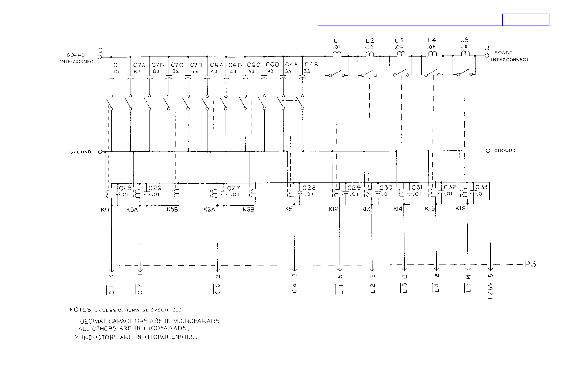
SUNAIR CU-9125
Figure 5.13 Intermediate Board Assembly 2A2A2, page 2 of 2.
5-53
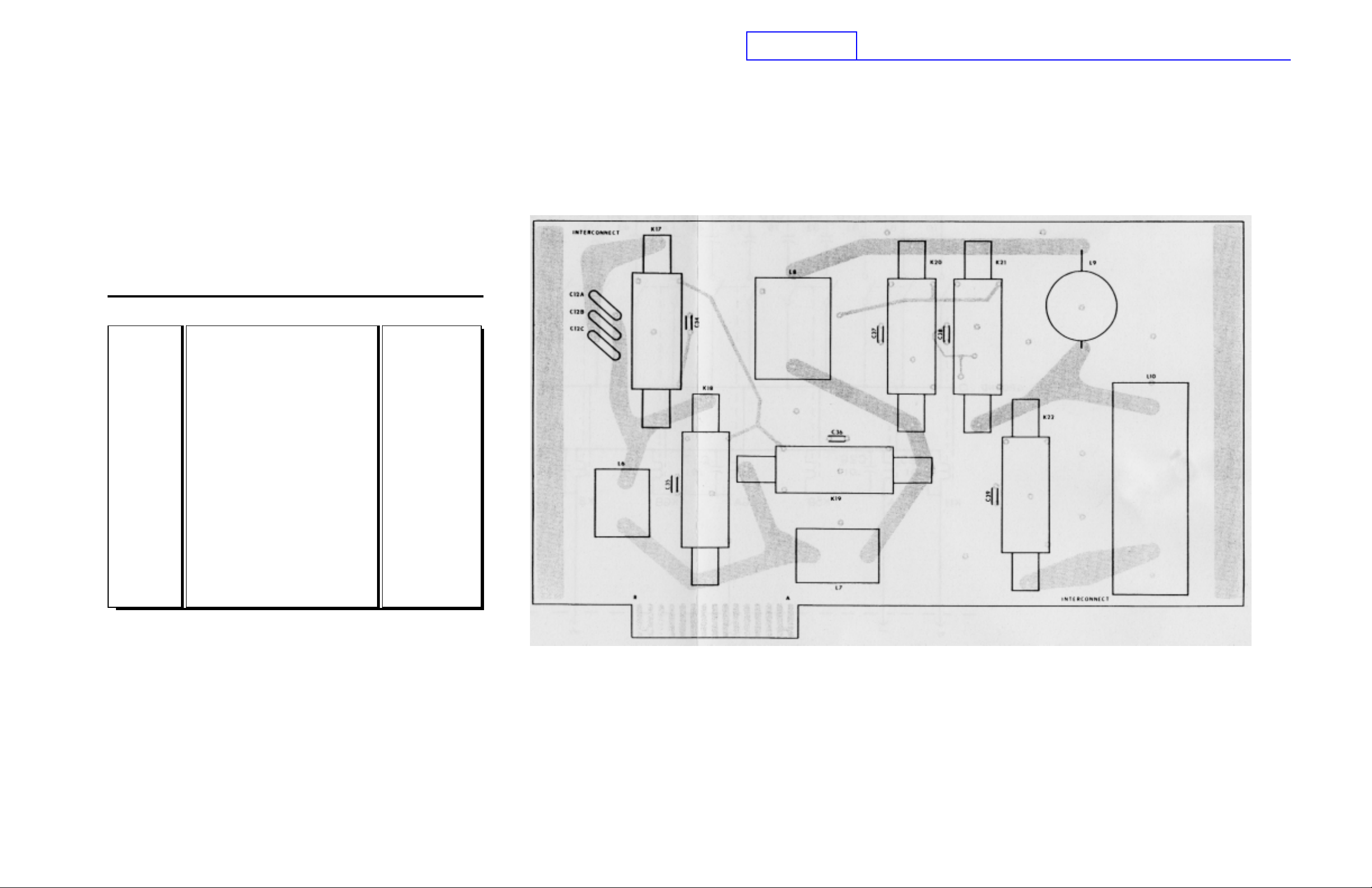
PC ASSY, INDUCTOR BOARD CU-9125 (2A2A3)
SUNAIR CU-9125
C12A
C12B
C12C
C34
C35
C36
C37
C38
C39
K17
K18
K19
K20
K21
K22
L6
L7
L8
L9
L10
PC ASSY, INDUCTOR BOARD
CAP. 10PF, 3K0V NPO
CAP. 10PF, 3K0V NPO
CAP. 10PF, 3K0V NPO
CAP. 0.1µF, 50V, X7R, 20%
CAP. 0.1µF, 50V, X7R, 20%
CAP. 0.1µF, 50V, X7R, 20%
CAP. 0.1µF, 50V, X7R, 20%
CAP. 0.1µF, 50V, X7R, 20%
CAP. 0.1µF, 50V, X7R, 20%
RELAY, REED, HV, 24V, 1 FORM A
RELAY, REED, HV, 24V, 1 FORM A
RELAY, REED, HV, 24V, 1 FORM A
RELAY, REED, HV, 24V, 1 FORM A
RELAY, REED, HV, 24V, 1 FORM A
RELAY, REED, HV, 24V, 1 FORM A
INDUCTOR, O.35µH
INDUCTOR, O.70µH
INDUCTOR, 1.33µH
INDUCTOR, 2.62µH
INDUCTOR, 5.64µH
8080050091
0259690007
0259690007
0259690007
0281610002
0281610002
0281610002
0281610002
0281610002
0281610002
1005920001
1005920001
1005920001
1005920001
1005920001
1005920001
8080050601
8080050708
8080050805
8080050902
8080051003
5-54
Figure 5.14 Inductor Board Assembly 2A2A3, page 1 of 2.
 Loading...