

Page 1
- 1-
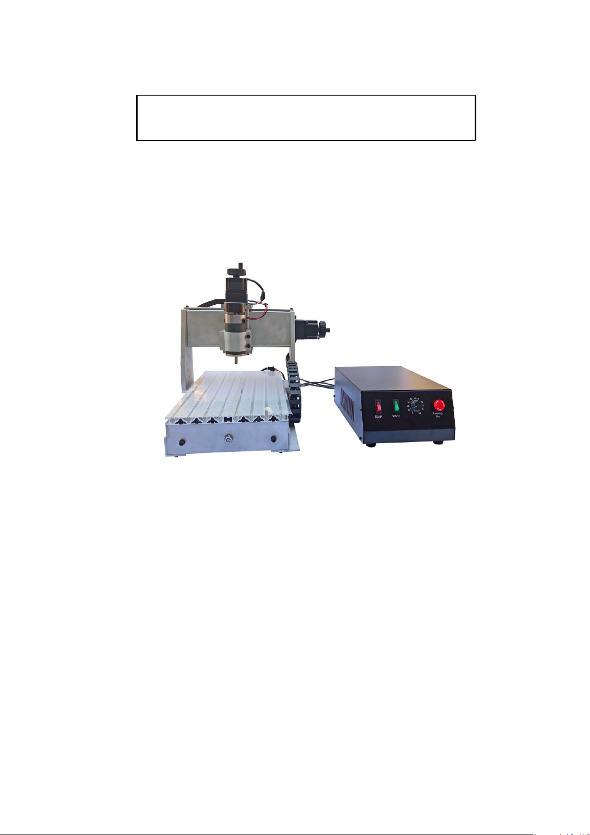
Small CNC User Manual
Applicable Model:CNC2030/3040/4060 model
SUMTOR(Wuxi) Electric CO.,Ltd.
Page 2

- 2-
Table of Contents
.
Foreword ........................................................................................................................... 3
1.Equipment overview ................................................................................................... 4
1.1. Equipment packing list ........................................................................................4
1.2. Name s and functions of various parts of the equipment .....................................5
1.3. Equipment technical parameters ....................................................................... ..6
Equipment installation and commissioning ............................................................. 6
2
2.1. Installation precautions ..................................................................................... ..6
2.2. Installation instruc tions .................................................................................... ..7
2.3. Control sof twa re in st al la ti o n ............................................................................ ..9
2.4. Equipment debugging instructions ................................................................... ..9
3.Equipment instructions .............................................................................................. 10
3.1. Processing flow ...................................................................................................10
3.2. Introduction to com mon functions of Mach3 ................................................... .12
3.3. Compatible programming software .................................................................. .14
4.Tool selection ............................................................................................................. 14
5.Common material processing parameters .............................................................. 16
6.Equipment service .................................................................................................... 17
Page 3

- 3-
Foreword
First of all, thank you for purchasing and using our products.
Please read this instruction before installing your machine, so as
not to cause unnecessary trouble for your ins tallation and us e .
The equipment is tested before leaving the factory and mee ts
the shipping standards. Before using, please read the following
precautions carefully: 1. The machine has been rigorously tested
before leaving the factory to ensure that all functions of the
machine are in good condition, but the machine must be
transported by logistics. When receiving the goods, please make
sure that the outer packaging of the product is complete and
unpacking. Please check the goods afterwards. If there is any
problem, please contact the after-sales personnel in time; 2. The
machine is connected with the computer by USB, the computer
used for contro l should be dedic a t e d, a nd a s fa r a s poss i ble, do not
install other unrelated application software; Please ensure that
there is a grounding function for the power supply socket. If there
is no grounding, please perform external grounding. 4. This unit
uses single-phase AC 220V, 50Hz (single-phase AC110V,
50/60Hz in some areas), if not allowed, please Do not
disassemble it in order to avoid danger;5. When processing, it is
relatively large when it comes to cutting chips. Especially when
processing metal materials, please wear protective glasses to
prevent metal chips from flying out and hurt your eyes. 6. Do not
approach the spindle rotating at high speed during machining. Do
not touch the workpiece being processed by hand to avoid danger.
7. If accidents are found during work, please turn off the power in
time and wait for a while before re-us e. If the problem is still not
solved, please contact the after-sales personnel.
Page 4

- 4-
1. Engraving overview
1.1. Equipment packing list
(1).CNC Engraving machine rack----1 units
(2).CNC Engraving m ac hine con tr ol bo x----1 units
(3). Set of random accessories:Test machine car vi ng k nif e ----5 Put
Fixed clamp ----4 sets
Spindle chuc k ----1PC
Spindle wre nch ----1 pair
Allen wrench --- 5 put
power cable ----1 Articles
USB cable ----1 Articals
Tool set ----1 PC
Small table la mp ----1 units
U disk ---- 1PC
(4). Engraving machine spindle cooling pump ----1 units(4060 model)
The above items are the packing list when the machine is shipped as standard. The specific
goods are subject to the purchase.
If there is any missing item, please contact customer service.
Page 5
- 5-
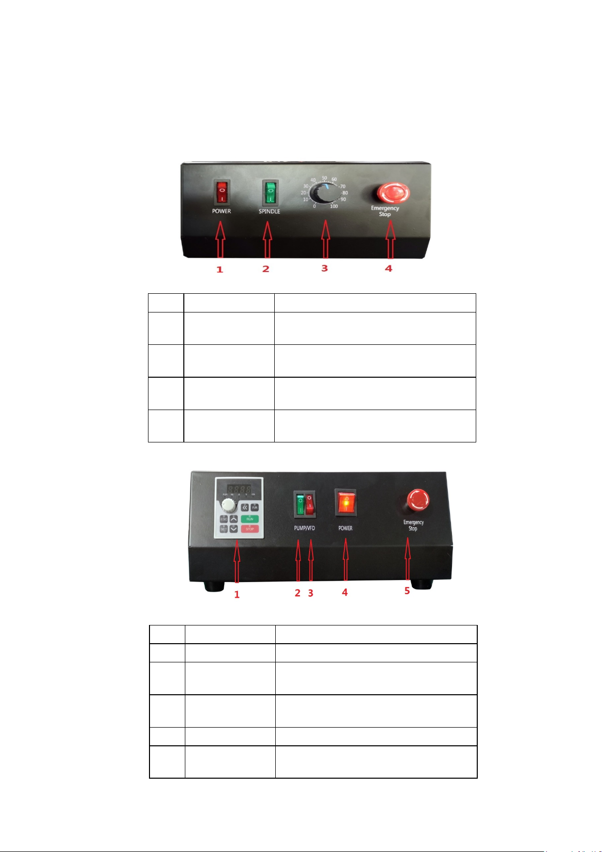
1.2. Names and functions of various parts of the equipment
Label
Button name
Key Function
1
Control the power supply of the electric
control box
2
switch
3
control knob
speed
4
button
will stop immediately
Label
name
Key Function
1
Spindle panel
Display spindle status
2
switch
cooling water pump
3
switch
4
switch
Control the power of the control box
5
switch
will stop immediately
Electric control box
switch desc ription
2030/3040 model
switch
Spindle start
Spindle speed
Emergency stop
Control spindle start and stop
Adjust the spindle switch and spindle
Pressing the machine in an emergency
4060 model
Water pump
Control the start and stop of the spindle
Spindle start
Control spindle start and stop
Emergency stop
Pressing the machine in an emergency
Page 6

- 6-
1.3. Equipment technical parameters
DKJ3Z3020DKJ00001
DKJ4Z3020DKJ00001
DKJ3Z3040DKJ00001
DKJ4Z3040DKJ00001
DKJ3Z6040DKJ00001
DKJ4Z6040DKJ00001
Effective work
schedule
Effective work
schedule
Maximum
material
Maximum
workpiece size
working de sk
size
Frame
material
6061 aluminum alloy + 6063
aluminum alloy
6061 aluminum alloy + 6063
aluminum alloy
6061 aluminum alloy + 6063
aluminum alloy
Drive unit
(X/Y/Z)
Sliding unit X
axis
Slide unit Y
axis
20mm Aluminum support optical
axis slide
Sliding unit Z
axis
Stepper motor
type
0~8000rpm/ min
Stepless speed
regulation )
0~8000rpm / min
Stepless speed
regulation )
0~24000rpm/min
Frequency
converter speed regulation )
speed
0-1000mm / min
Different
materials )
0-1000mm / min
Different
materials )
0-2000mm / min
Different
materials )
Machine
weight
SKU
Chinese name
thickness of
Spindle motor
Spindle speed
3020 3 axis / 4 axis 3020 3 axis / 4 axis 6040 3 axis / 4 axis
200(X)x300(Y)x55(Z)mm 300(X)x400(Y)x55(Z)mm 395(X)x600(Y)x70(Z)mm
500*390*390(H)mm 610*450*390(H)mm 840*640*460(H)mm
≤65mm ≤65mm ≤100mm
240mm * 425mm 320mm * 525mm 750mm * 480mm
240mm * 425mm * 15mm 320mm * 525mm * 15mm 750mm * 480mm * 15mm
1202 Trapezoidal screw 1202 Trapezoidal screw New 1605 ball screw
16mm Chrome plated hard shaft 16mm Chrome plated hard shaft 16mm Chrome plated hard shaft
16mm Chrome plated hard shaft 16mm Chrome plated hard shaft
12mm Chrome plated hard shaft 12mm Chrome plated hard shaft 13mm Chrome plated hard shaft
57 2-phase stepper motor -2A 57 2-phase stepper motor -2A 57 2-phase stepper motor -3A
300W DC 300w DC 800w New water cooled spindle
(
(
(
Airspeed
Engraving
Repeatability
2.
Equipment installation and commissioning
0-1000mm / min 0-1000mm / min 0-2500mm / min
(
≤0.05mm ≤0.05mm ≤0.03mm
21.5KG/23.5KG 25.5KG/27.5KG 51KG/59KG
(
(
2.1. Installation precautions
(1). This machine uses a USB p ort to connect to the computer . When installing, you need t o connect the USB cable to th e computer.
(2). The computer use d f or c ontr o l shou ld b e de dica te d. D o no t in stal l ot her unr ela te d
application sof tw ar e and a nt i-virus software a s m uch a s possib le . A lso, do n ot c on nect t o the
network. Viruse s an d other application sof t wa re may af fe ct the ope ra tion of the machine.
(3). The machine adopts single-phase A C 220V, 50Hz power supply (single-phase A C 110V, 5 0 / 60 0 z z in some are a s), please ensure the correct and stable supply voltage;
Page 7
- 7-
(4). Since the machine has a frequency converter, the inverter will generate a lot of static
electricity durin g op era tio n. P lea se en sur e t hat t he gr o undi ng f un c tion of t he pow er supply
socket of the equ ipment is normal. I f it is no t gro un ded, it w il l aff ect the l ife and normal
operation of the m achi ne.
(5). Please be sure to f oll ow the steps of the engraving machine in stal la t ion in str uc ti ons during installa t ion. T he inst allation may cause the machine to malfunct io n d ue to i ncor r ec t installation by the user.
(6). If there is any pr oblem with the operati on of t he machine during the machine debuggi ng process, please contact the after-sales personne l f or di sp osal. D o not disa sse mble it without permission, so a s to a voi d da nger;
(7). Do not plug or unplu g th e te rminal at any tim e while powe ri ng o n. A t the same time,
please note tha t the i n terva l betw ee n the po we r on and of f of the devi ce sh ou ld be a b ove 15S.
If you do not pay attenti on t o th e a bove pro blems, it may cause damage to the control circuit.
2.2. Installation instructions
The machine can be ins ta lle d by following the instr uc ti on s below.
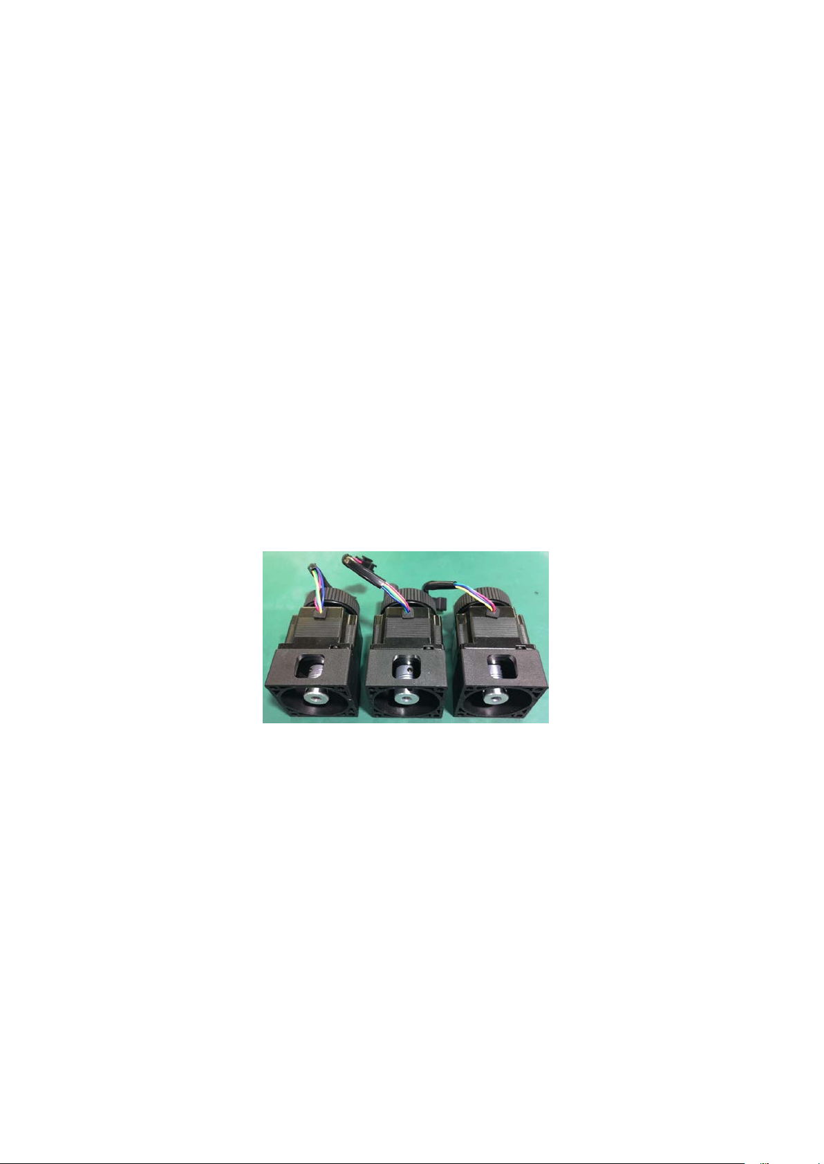
Step 1: Install the motor , a nd in stal l th e ste ppi ng motors of the three axe s t o the
corresponding s haf ts. T he loc ki ng sc rew s o n the c o upl ing s a re tig hte ne d w ith the A lle n key.
Step 2: Align the w ire plu g on t he motor with the corre sp on ding p lug on t he m a chine .
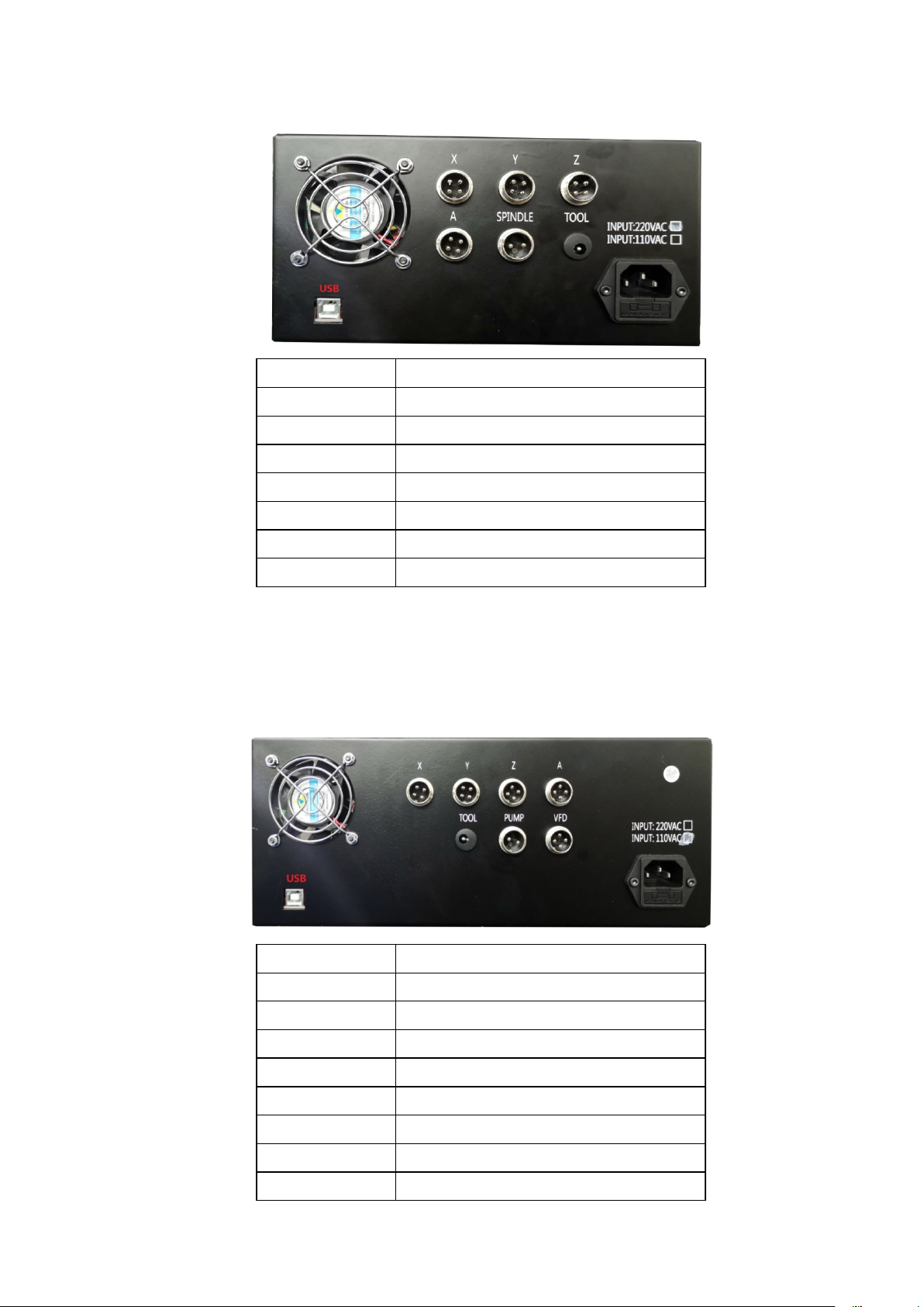
Step 3: Conne ct the engrav ing machine frame, electric control box a nd computer
wiring (refer to the wiring diagram for c onnection). T he aerial plug-in cable is connected
between the rac k and the e le ctr ic c on tr ol bo x. The connection will be affixed with X, Y, Z,
A (purchasi ng A-axis), spindle, spindle cooling water pump (4060 model) corresponding
to the aviation plug and T he interfaces with the same identification after the electric
control box are connecte d one by one. Co nnect the USB cable between the electric control
box and the computer. Be sure to connect the wiring. Otherwise, the computer will not be
able to control the machine. Finally , connect the power cable.
Page 8
- 8-
2030/3040 model wiring diagram
Label name
Port description
X
X-axis motor
Y
Y-axis motor
Z
Z-axis motor
A
A-axis motor
SPINDLE
Spindle motor
TOOL
Tool set
USB
Connect the data cable to the computer
Label name
Port description
X
X-axis motor
Y
Y-axis motor
Z
Z-axis motor
A
A-axis motor
TOOL
Tool set
PUMP
Spindle motor cooling water pump
VFD
Frequency conversion spindle
USB
Connect the data cable to the computer
4060 model wiri ng diagram
Page 9
- 9-
2.3. Control software installation
Software install at io n computer requirements:
1. desktop computer or laptop; 2. USB port; 3, computer
system:WindowsXP/Win7/win8/win10 system;
Our company provides Mach 3 sof tware for testing and testing. It is only f or teaching and
personal research. If there is any commercial use, please buy genuine , thank you! Mach 3
official website: www.machsupport.com
Basic install at ion of Mac h 3 sof twa re : P lease open the supplied USB flash drive and find the
installation folder.
Please conf ir m that the USB cable is connected before the software is installed. Sof tware
installation steps: Double click .
Open into the installation interface, and then pres s the Enter key "Enter", "Next" or "YES"
until The "Finish" in stallation is c omplete: > > Next > Yes >
Next > Next > Next > Next > Determine > Finish > Determine > Next > Yes > Next >
Next > Next > Next > Yes > Finish.
2.4. Equipment debugging instructions
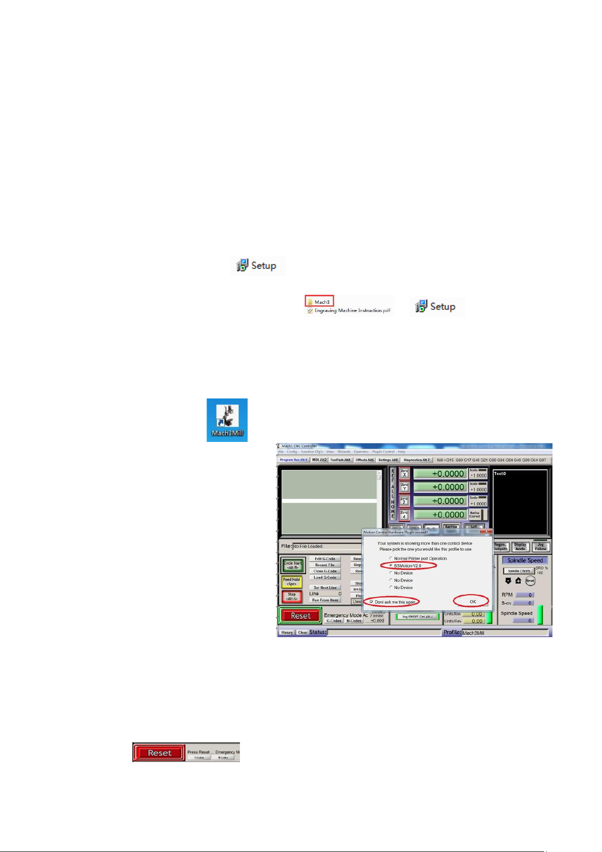
Step 1: Double-click to
enter the software and wait for
the softwar e software in te rface
to load. The first time you start
the softwar e, the computer will
pop up the following dialog box,
please select "BS M ot io n-V2.0",
"Don't ask me this again", "OK"。
Step 2: Power on the c ontrol b ox and sw itch t he power switch t o ON. At this tim e, the
emergency reset button “Reset” in the lower left corner of the computer control interface i s
flashing. Click the “ Reset” bu tton to c ance l the alar m sta te.
Page 10
- 10-
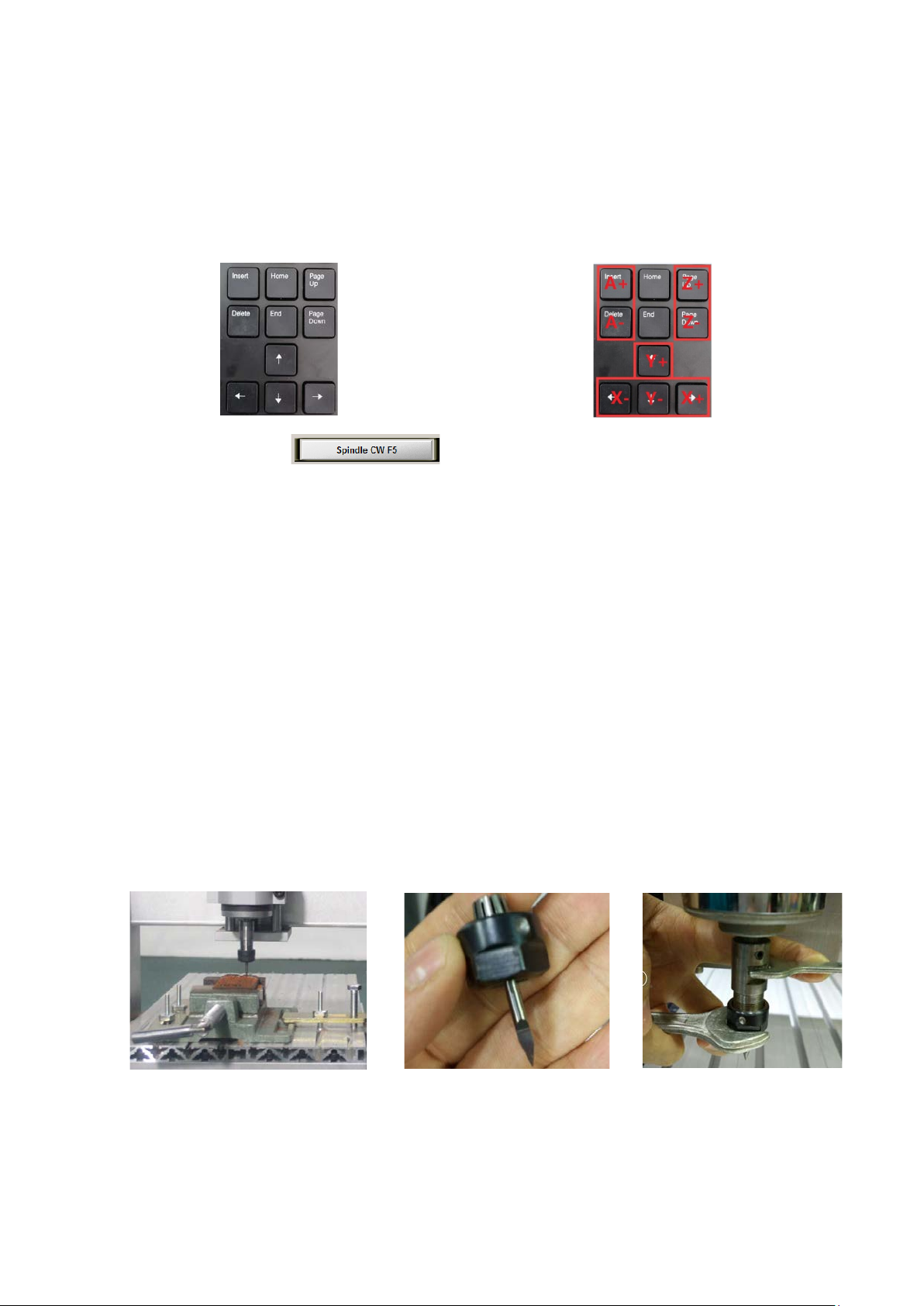
Step 3: After c onfirm ing tha t the e me rgency reset in the lower left c orner is not fla shing,
use the arrow keys on t he key board an d Pageup /down t o contr ol the left and r ight, f ront an d
rear, and up a nd down m ovem ents of t he m achine to co nfirm that th e mac hine m oveme nt
function is norm al.
Step 4: Then c lick on the spindle speed bar in the lower right corner
of the Mach3 software. A t this time, the spindle will rotate, indicating that the spindle
speed contr ol function is normal (make sure the spindle nut is tightened before
turning on the spee d) .
After the above simple debugging, the machine functions are normal. If you
encounter problems, you can consult the after-sales sol uti on.
3. Equipment instructions
3.1. Processing flow
Step 1: the material to be processed is fixed on the machine with the corresponding fixture.
Generally, the thin plate is fixed by double-sided glue, the rectangle is fixed by a vise, and the
shaped workpiece is fixed by a special fixture.
Step 2: Clamp the tool onto the spindle motor. When clamping the tool, it is necessary to pay
attention to the specifications of the clamping tool. It must be the same as the programming
time. The tool should be locked with the spindle wrench. After the tool is clamped, it must be
Page 11
- 11-
checked whether the tool will be yawed. Otherwise, the quality of the processed product will
be poor. Broken knives, etc. during processing.
Step 3: Open the control software Mach3 on the computer, turn on the machine power switch,
and release the alarm state.
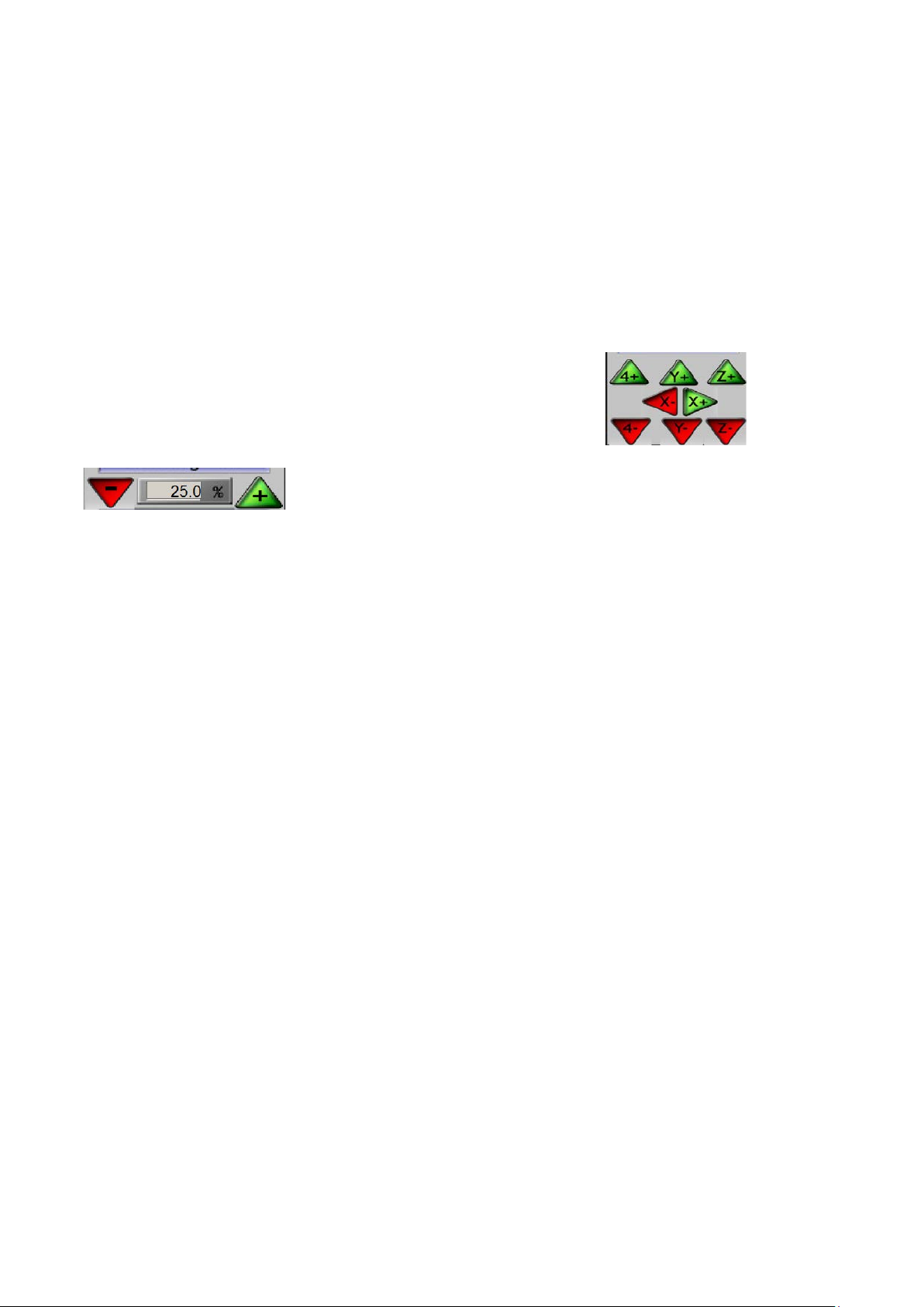
Step 4: manual tool setting operation, press the keyboard “Tab” on the computer operation
interface to call up the “MPG” interface, click the corresponding button to control the
forward/reverse movement of the machine in the current axis. by
To control the speed of the movement, move the center of the tool
nose to the machining coordinate origin set during programming (f or the convenience of tool
setting, the programming is usually set at the four corners or the center of the material). For
example, when programming, the origin is set in the lower left corner of the m aterial, then we
will align the center of the tool tip with the bottom left corner of the material with the hand
wheel (the spindle speed should be adjusted to about 30% when the tool is set to prevent the
tool from breaking. Knife).
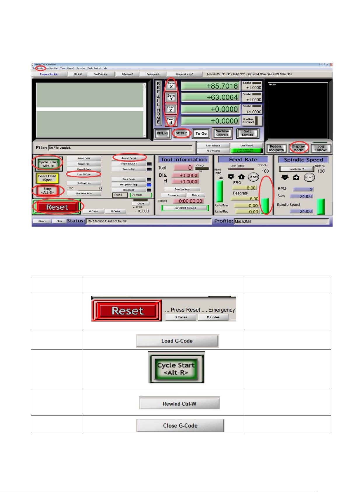
Step 5: Co nfir m that the “Emergency Reset” in the lower left corner of the software is not
flashing. Click “Zero X”, “Zero Y”, “Zero Z”, “Zero A ”, clic k “ Loa d G C ode ”, th en t her e
will be loading. G code pop-up window, file type select "AllFiles" and find the G code you
generated is loaded. After the loading is completed, the corresponding simulation path will be
displayed in the upper right corner of the software (if there is no simulation path generation,
the loaded G code is wrong or Can't identify it).
Step 6: After the program is read in, adjust the spindle speed to 80%~100% (the spindle
speed is set according to the processing material), then click “Start” to process the machine.
If it needs to be adjusted during the machining process. The speed of the machining can be
controlled by pulling the column bar of the feed bar.
Page 12
- 12-
Click this button to import the G
After importing the G code file,
Close G code file
The above is a simple operation method. For details on the control software, please refer to “Using Mach3 Mi ll” .
3.2. Introduction to common functions of Mach3
Button name
Emergency reset
Load G code
The program starts
running
Return to program
beginning
Button icon Key Function
When alarming, click this button
to cancel the alarm.
code file.
Click this button to start running
the program.
Click this button to return to the
beginning of the program and
re-run.
Turn off G code
Page 13
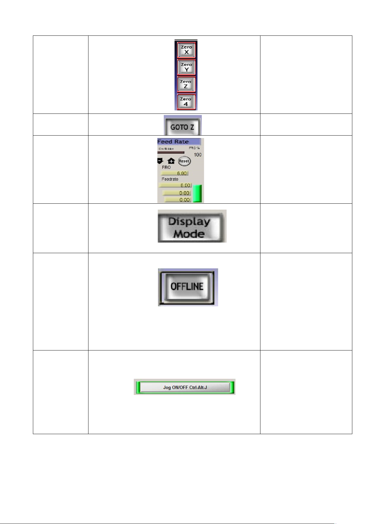
- 13-
XYZA coordinate
Click this button to return to the
Flat 2D mode and stereo 3D
processing path, click this button
If you need to check the starting
clear
After using the correct origin
before machining, we need to
click XYZA to clear in mach 3,
that is, set the workpiece zero
coordinate;
Return to origin
Processing feed
speed
adjustment
Display mode
Offline function
origin coordinates.
If you need to adjust the
processing speed during
machining, you can click this
column to adjust the machining
feed speed.
mode display Show the
to switch the display status
point or running status of the
program, you can click this
button to perform offline
simulation. After offline lighting,
reconnect the machine and
remember to switch back.
Otherwise, the computer cannot
control the machine.
Jog on/off
Similar to a child lock function,
when you click this button,
the computer keyboard will
not be able to control the
machine, and the program
can still run on line.
Page 14

- 14-
3.3. Compatible programming software
Mach3 is a PC software that recognizes international G code and is currently
compatible with most software that generates G code on the market. Since the user's
purchase of the machine is not the same, here are some recommended G code
generatio n software for common use.
For two-dimensional processing applications such as engraving, milling, drilling, and
cutting, it is recommended to use Wentai, ArtCAM, Beijing Jinghua software, Type3
and other sof tware, they are compatible with DXF format files.
PCB board engravin g is recommended to use CopperCAM softwar e and is compatible
with Gerber f iles.
Engraving relief is recommended to use ArtCAM and Beijing carving software,
ArtCAM is suitable for novice learning, Beijing carving
The softwar e is more professional.
UG, MasterCAM, and Powermill are recommended for processing such as molds,
fixtures, and parts. Four-axis stereo processing is recommended to use Powermill and
Beijing Engraving softwa re to make getting started easie
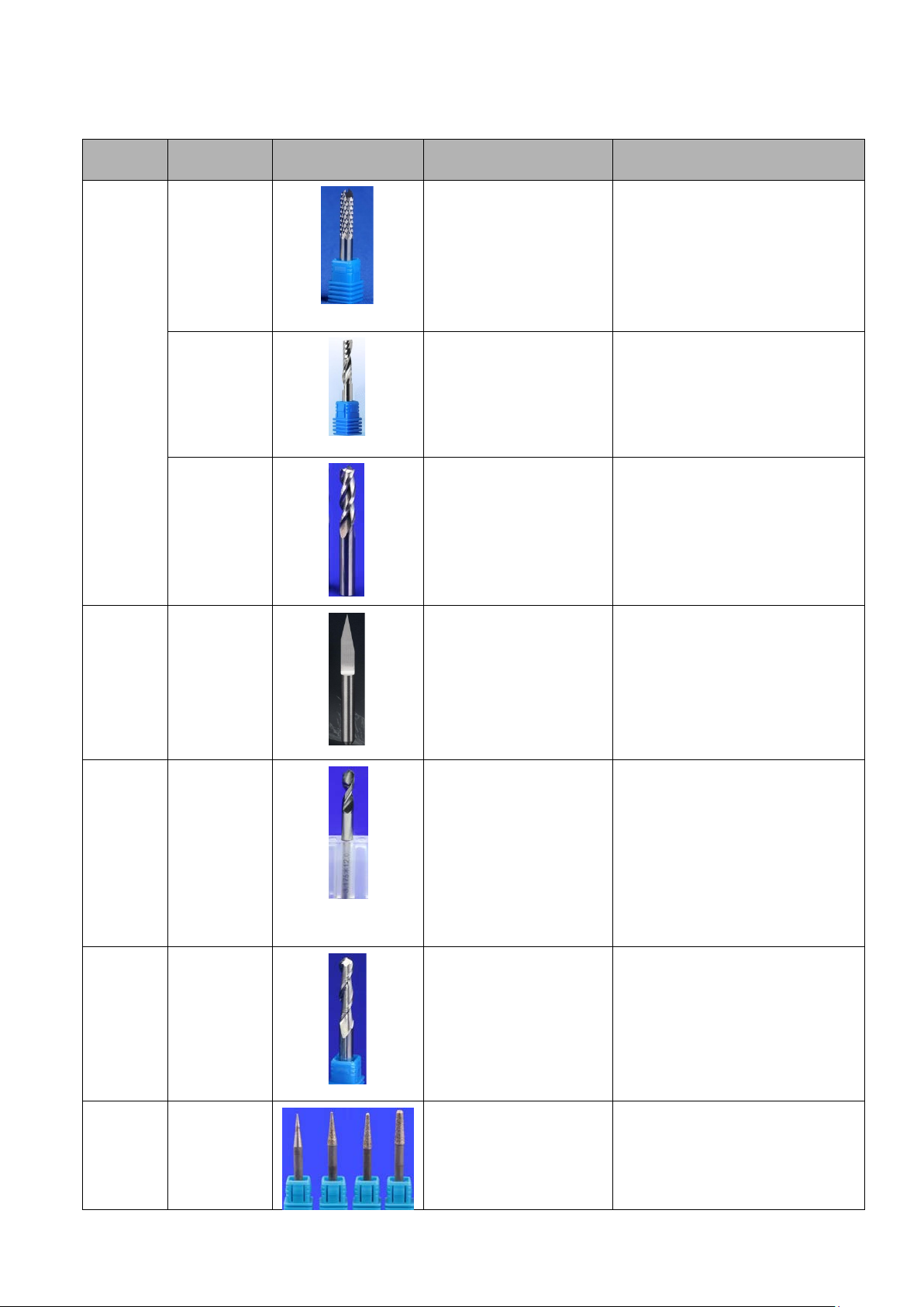
4. Tool selection
Commonly used tool classification for engraving machines: milling
cutters, engraving knives, drill bits, chamfering knives, ball knives, etc.
The tool usually consists of a shank and a blade. The shank is the part
that is clamped and has no cutting ability. The blade is the part with
cutting ability.
Page 15
- 15-
List of commonly used tool types
Mainly used for milling
For the cutting of plastic ,
Common specifi cations of the tool
Processing aluminum alloy,
copper and other materials,
also be used for processing
Specifications: 1, 1.5, 2, 2.5, 3, 3.5, 4, 5,
Generally used for
Common specifications of the tool
holder: 3.175, 4, 6mm blade Common
specifications: 20°0.1, 0.2, 0.3, 30°0.1,
Suitable for PCB board
drilling, or plastic and
specifications, can also
drill aluminum alloy
Tool type Tool name Tool picture Tool function usual format
Milling
cutter
Carving
knife
Corn milling
Single-edged
milling cutter
Three-blade
milling cutter
Flat bottom
cutter
taper
carving
knife
grooves of non-metallic
materials such as high
temperature resistant
plastics and wood.
copper, alum inum alloy
and other material s,
milling
Common specifications for to ol
holders: 3.175 and 4m m
Common specifications of the blade:
0.6-3.175mm
holder: 3.175 blade
common specifications : 1,
2, 3mm
Common spe cificat ions of the sha nk:
milling and milling, can
non-metal bakelite,
3.175 and 6m m bla des c omm only us ed
6mm
plastics, etc.
engraving PCB board
engraving, metal lettering,
embossing process
0.2, 0.3, 0.4
processing and so on.
High speed
Drill class
PCB
drill
head
Ball knife
Grinding
head
Ball knife
Jade grinding
head
other holes,larger
Common specifications of the shank:
3.175mm blade com monly used
Specifications: 0.3-3, 4, 5, 6mm
materials
Used for the processing of
some curved sp herical
surfaces such as plastic,
wood and metal.
For the grinding of jade
materials
Tool holder common
specifications: 3.175mm
Page 16

- 16-
Processing parameters
Eat the amount of
Lower knife speed
Cutting speed
Spindle speed (r/min)
wood
2
1000
20000
Acrylic
1
800
16000
PVC
1
800
18000
PC
1
800
18000
ABS
0.5
800
18000
nylon
0.5
1000
20000
Double
1
1000
20000
Bakelite
1
1000
20000
Fiberglass
1
1000
20000
Mammoth
0.5
800
20000
Beeswax
0.5
800
20000
Bone/corner
0.5
800
20000
copper
0.25
800
20000
aluminum
0.25
1000
20000
silver
0.3
1000
20000
Zinc
0.2
800
20000
magnesium
0.2
800
20000
walnut
1
800
20000
Ivory fruit
1
800
20000
Bodhi
1
800
20000
synthetic rock
1
300
20000
Seal stone
1
300
20000
cobblestone
0.1
300
20000
jade
0.1
300
20000
Carbon fiber
0.3
800
20000
The above data is a conservative parameter set by a 3.175mm milling cutter. For
Material
name
5. Common material pro cessi ng parameters
knife (mm)
(mm/min)
500
500
500
500
500
500
500
500
(mm/min)
panels
500
300
300
300
400
400
400
400
400
400
400
400
200
200
200
150
board
400
reference only, please adjust accord ing to the actual situation.
Page 17
- 17-
6. Equipment service
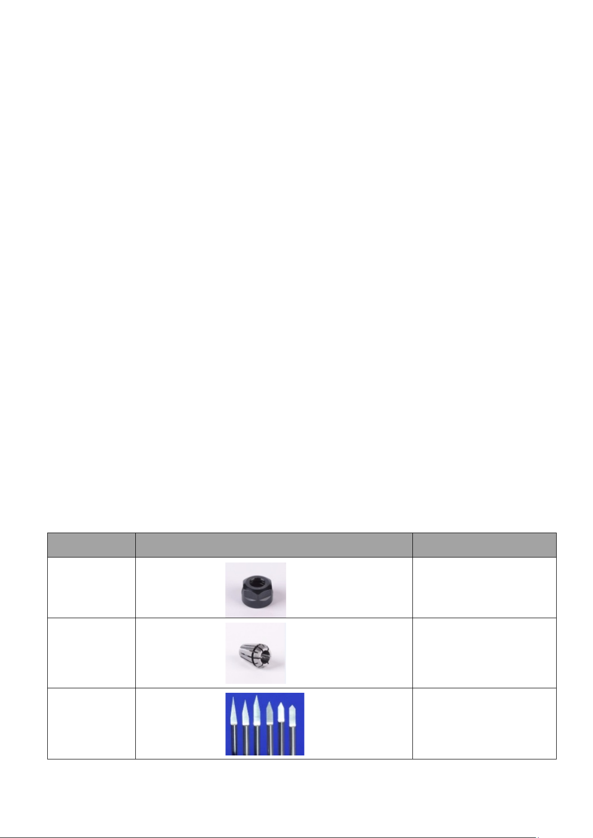
On the clamping spindle,
use the locking tool with the
tool chuck
On the clamping spindle,
use the locking tool with the
tool nut
Engraving tools such as
engraving knives, milling
cutters, drill bits, etc.
(1) screw cleaning and lubrication
When the machine is in use, it is a good habit. It is necessary to do a cleaning work
for about one month. The screw, optical axis and bearing cleaning must work. You can use
a clean rag to manually wipe the optical axis of the screw. The part of the bearing that is
not cleaned can be cleaned with a small brush. After cleaning, the oil can be sprayed with
oil to the screw, the optical axis and the bearing, and then the machine can be moved back
and forth for a few times, such as above the screw. There is also dirt, re-clean with a rag,
repeat the lubric a ti on a nd cle an th e act i on u ntil th e scr ew is shi ny and oily .
(2)
spindle cleaning and maintenance
During the machining process, the spind le chuck, nut and screw parts are easy to enter
dust and rust. At this time, it is necessary to apply anti-rust oil to the spindle clamping part
to clean the rust of the screw; the chuck and nut are severely rusted. Replace the collet and
nut to ensure that the machine is concentric.
(3)electric control box cleaning
When the controller is used with the machine, sometimes it will enter a lot of dust.
When processing metal materials, it is necessary to clean the dust inside the control box to
prevent conduction and burn out the circuit. We can open the cover of the controller, use a
hair dryer, open the cold air stall, turn the control box upside down, clean the dust on the
circuit board, a nd c lea n i t, c lean i t w ith a small brush.
(4)common consumables re placement
Shaft nuts, chucks, knives, stepper m otor couplings, lubricants, etc., please contact
Supplies Name Consumables Picture Supplies Features
Spindle nut
Tool chuck
Tool
 Loading...