

Page 1
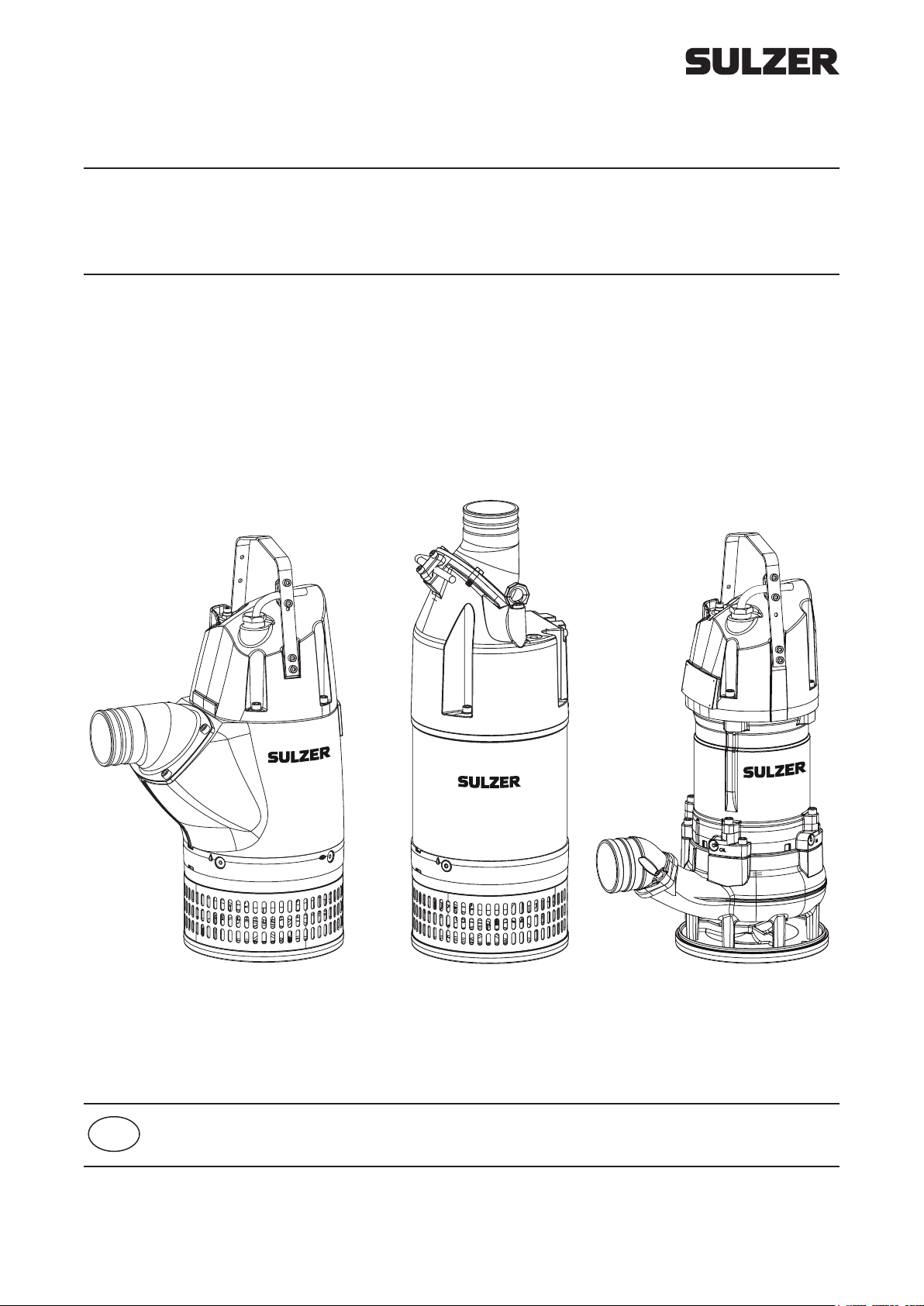
Submersible drainage pump XJ
Submersible drainage center-line pump XJC
Submersible sludge pump XJS
EN Workshop manual
00833219 AM 07.2019
www.sulzer.com
Page 2
Workshop manual
XJ 25 - 110, XJC 50 - 110, XJS 25 - 110
Submersible drainage pump XJ
XJ 25 ND (50/60 Hz) XJ 25 HD (50/60 Hz)
XJ 40 ND (50/60 Hz) XJ 40 HD (50/60 Hz)
XJ 50 ND (50/60 Hz) XJ 50 HD (50/60 Hz) XJ 50 LD (50/60 Hz)
XJ 80 ND (50/60 Hz) XJ 80 HD (60 Hz) XJ 80 LD (50/60 Hz) XJ 80 SD (50/60 Hz)
XJ 110 ND (50/60 Hz) XJ 110 HD (50/60Hz)
XJ 25 ND AT (50/60 Hz) XJ 25 HD AT (50/60 Hz)
XJ 40 ND AT (50/60 Hz) XJ 40 HD AT (50/60 Hz)
XJ 50 ND AT (50/60 Hz) XJ 50 HD AT (50/60 Hz) XJ 50 LD AT (50/60 Hz)
XJ 80 ND AT (50/60 Hz) XJ 80 HD AT (60 Hz) XJ 80 LD AT (50/60 Hz) XJ 80 SD (50/60 Hz)
XJ 110 ND AT (50/60 Hz) XJ 110 HD AT (50/60 Hz)
Submersible drainage center-line pump XJC
XJC 50 ND (50/60 Hz) XJC 50 HD (50/60 Hz) XJC 50 LD (50/60 Hz)
XJC 80 ND (50/60 Hz) XJC 80 HD (60 Hz) XJC 80 LD (50/60 Hz) XJC 80 SD (50/60 Hz)
XJC 110 ND (50/60 Hz) XJC 110 HD (50/60 Hz)
XJC 50 ND AT (50/60 Hz) XJC 50 HD AT (50/60 Hz) XJC 50 LD AT (50/60 Hz)
XJC 80 ND AT (50/60 Hz) XJC 80 HD AT (60 Hz) XJC 80 LD AT (50/60 Hz) XJC 80 SD (50/60 Hz)
XJC 110 ND AT (50/60 Hz) XJC 110 HD AT (50/60 Hz)
Submersible sludge pump XJS
XJS 25 (50/60 Hz) XJS 25 AT (50/60 Hz)
XJS 40 (50/60 Hz) XJS 40 AT (50/60 Hz)
XJS 50 (50/60 Hz) XJS 50 AT (50/60 Hz)
XJS 80 (50/60 Hz) XJS 80 AT (50/60 Hz)
XJS 110 (50/60 Hz) XJS 110 AT (50/60 Hz)
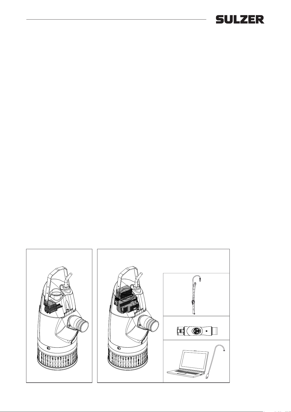
Standard version AquaTronic version
Accessories
Level sensor
AquaPlug
Service Data Kit
The manufacturer reserves the right to alter specications due to technical developments !
2
Page 3

Workshop manual
XJ 25 - 110, XJC 50 - 110, XJS 25 - 110
Contents
1 General ..............................................................................................................................................5
1.1 Service intervals ................................................................................................................................. 5
1.2 AquaTronic version ............................................................................................................................5
1.3 Repair kits and o-ring kits ...................................................................................................................5
1.4 Tools ................................................................................................................................................... 5
1.5 Complete pump overhaul ................................................................................................................... 5
1.6 Cleaning of pump before service .......................................................................................................5
1.7 Recycling in case of scrapping the pumps ......................................................................................... 6
2 Service inspection ........................................................................................................................... 7
2.1 Service Data Kit .................................................................................................................................7
2.2 Pump start and cable check ............................................................................................................... 7
2.3 Dismantling cover ...............................................................................................................................7
2.4 Insulation test ..................................................................................................................................... 8
2.5 Thermal sensors ................................................................................................................................9
3 Oil / Motor check ............................................................................................................................ 10
3.1 AquaTronic version ..........................................................................................................................10
3.2 Standard version and AquaTronic version .......................................................................................10
4 Hydraulic check .............................................................................................................................. 11
4.1 Wear ring ND, HD ............................................................................................................................ 11
4.1.1 Adjustment of wear ring ................................................................................................................... 11
4.2 Diuser ND, HD, LD ......................................................................................................................... 12
4.2.1 Dismantling of diuser ...................................................................................................................... 12
4.2.2 Assembly of diuser ......................................................................................................................... 12
4.3 Impeller ND, HD, LD ........................................................................................................................13
4.3.1 Dismantling of impeller ..................................................................................................................... 13
4.3.2 Assembly of impeller ........................................................................................................................ 13
5 XJ 80 SD, change of diusers, impellers and guide vane plate ................................................ 14
5.1 Dismantling ......................................................................................................................................14
5.2 Assembly ..........................................................................................................................................15
6 Primary seal and upper diuser ................................................................................................... 17
6.1 Dismantling of primary seal and upper diuser ................................................................................ 17
6.2 Assembly of primary seal and upper diuser ................................................................................... 17
7 Complete pump overhaul / dismantling ....................................................................................... 19
7.1 Electronics ........................................................................................................................................19
7.1.1 AquaTronic version ..........................................................................................................................19
7.1.2 Standard version .............................................................................................................................. 19
7.2 Oil/motor, hydraulic, primary seal and upper diuser .......................................................................19
7.3 Secondary seal ................................................................................................................................19
7.3.1 Dismantling of secondary seal .........................................................................................................19
7.4 Rotor unit ..........................................................................................................................................20
7.4.1 Dismantling of rotor unit ...................................................................................................................20
7.5 Dismantling of ball bearings ............................................................................................................. 21
7.6 Stator ................................................................................................................................................21
7.6.1 Insulation check ...............................................................................................................................21
7.6.2 Dismantling of stator ........................................................................................................................21
3
Page 4

Workshop manual
XJ 25 - 110, XJC 50 - 110, XJS 25 - 110
8 Complete pump overhaul / assembly ........................................................................................... 22
8.1 General ............................................................................................................................................22
8.2 Assembly of ball bearings ................................................................................................................22
8.3 Assembly of stator ............................................................................................................................22
8.4 Secondary seal ................................................................................................................................23
8.5 Primary seal and upper diuser .......................................................................................................23
8.6 Impeller ............................................................................................................................................23
8.7 Assembly of diuser ......................................................................................................................... 23
8.8 Base plate and strainer ....................................................................................................................23
8.8.1 With distances .................................................................................................................................. 23
8.8.2 Without distances ............................................................................................................................. 23
8.9 Relling of oil .................................................................................................................................... 24
8.10 Change of cable gland .....................................................................................................................24
8.10.1 Change of cable gland .....................................................................................................................24
8.10.2 Change of AquaTronic connection interface ....................................................................................24
8.11 Assemble the top cover ....................................................................................................................25
9 Testing .............................................................................................................................................25
10 Electrical information and wiring diagrams ................................................................................26
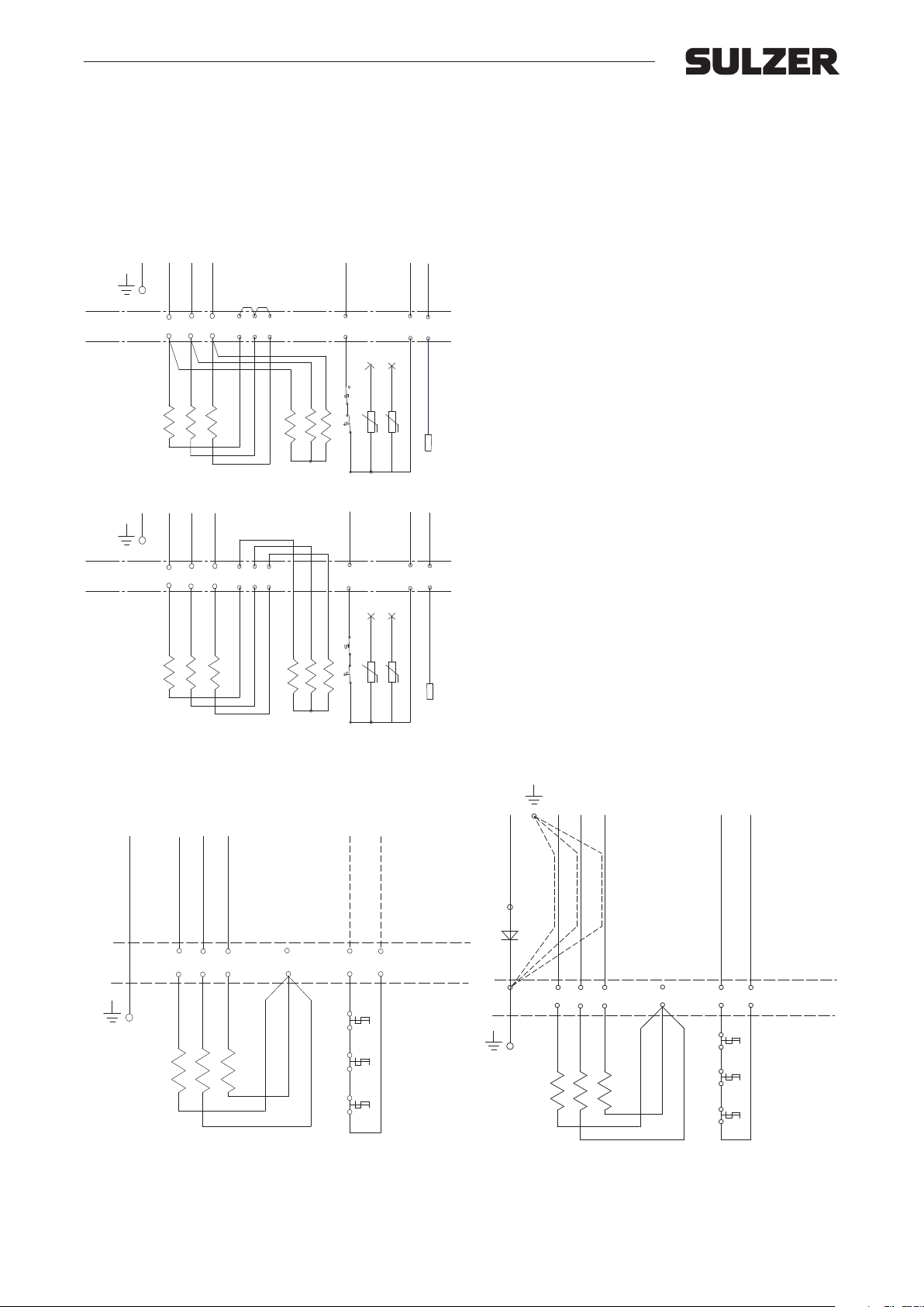
10.1 Three phase Direct Start D.O.L. with contactor ...............................................................................26
10.2 Three phase Direct Start D.O.L. with AquaTronic ........................................................................... 27
10.3 Three phase Soft Start with AquaTronic ...........................................................................................28
10.4 Three phase Direct Start D.O.L. with terminal block ........................................................................ 29
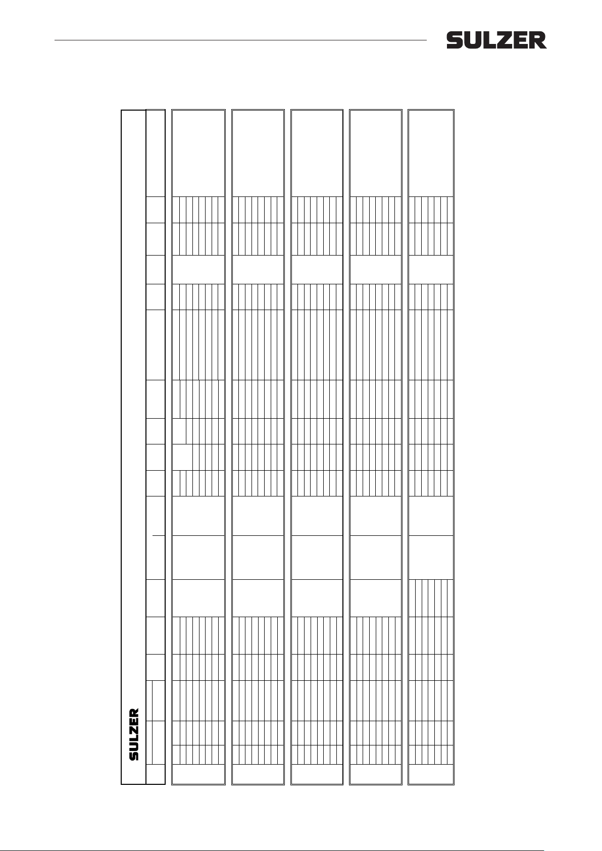
10.5 Winding data ....................................................................................................................................30
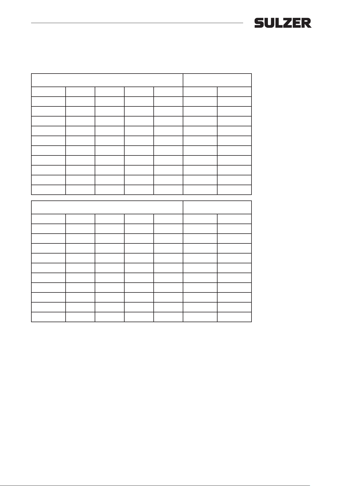
10.6 Fuses ...............................................................................................................................................31
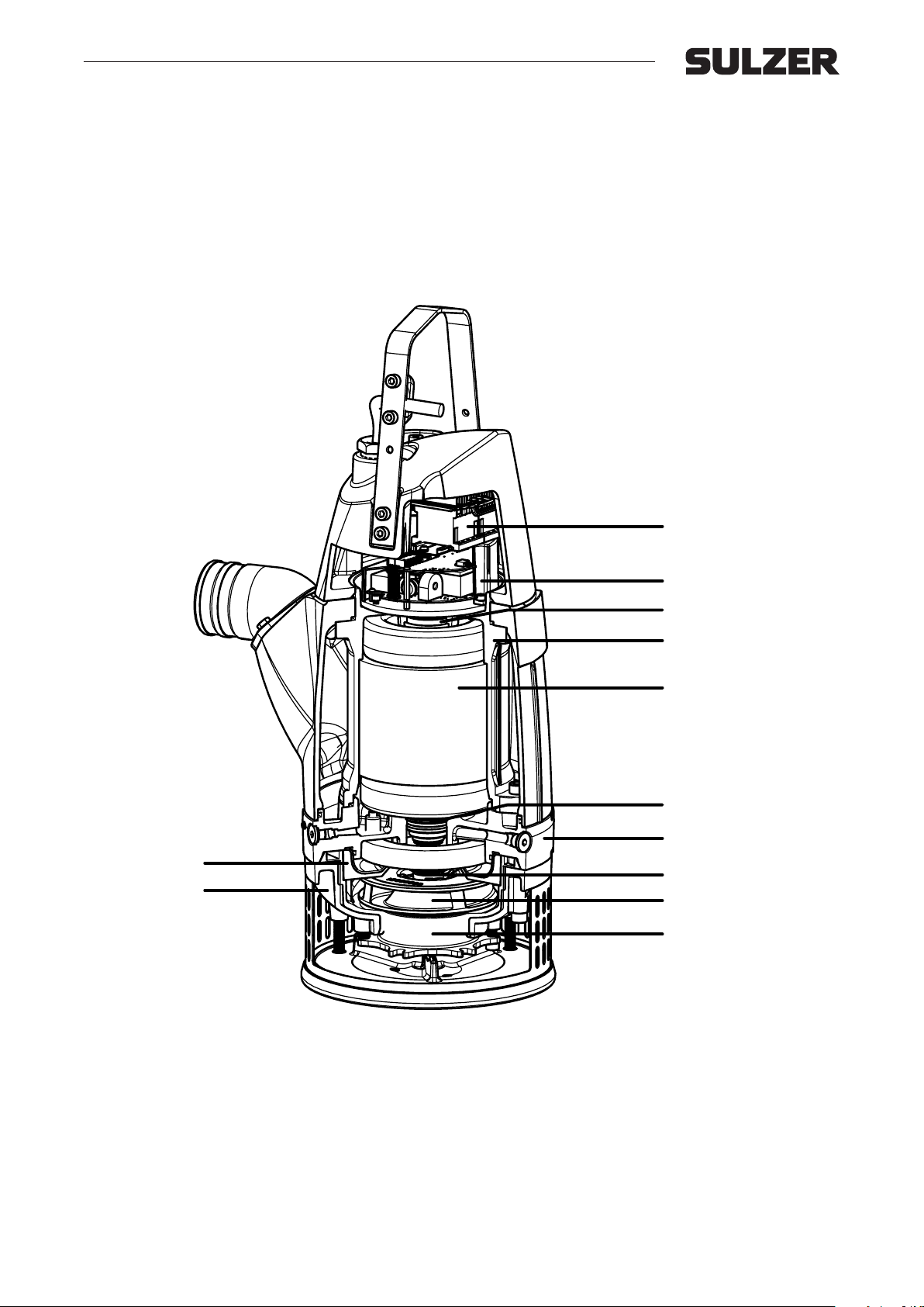
11 Sectional drawing ..........................................................................................................................32
12 Troubleshooting .............................................................................................................................34
12.1 Troubleshooting on eld ................................................................................................................... 34
12.2 Troubleshooting/service inspection without service program ........................................................... 34
12.3 Troubleshooting/service inspection with Service Diagnostic Program for AquaTronic ..................... 35
4
Page 5
Workshop manual
XJ 25 - 110, XJC 50 - 110, XJS 25 - 110
1. General
1.1 Service intervals
This workshop manual can be used for both regular inspection and complete overhaul on the pump. For assistance contact Sulzer workshop or by Sulzer authorized workshop.
- For regular inspection on the pump such as electrical check, oil/motor check and check of hydraulic parts,
proceed and follow chapter 1 to 5 in this manual.
- For complete overhaul on the pump proceed and follow chapter 1 to 9 in this manual.
- For electrical information and wiring diagrams see chapter 10.
Submersible drainage pumps XJ 25-110, Submersible drainage center-line pumps XJC 50-110 and Submersible sludge
pumps XJS 25-110 are built for long periods of trouble free operation. The pumps can “run on snore” without any risk for
the mechanical seals. They get sucient cooling from the pumped media and sucient lubrication and cooling from the oil
in the housing between the seals. All the ball bearings are sealed and prelled with high performance bearing grease for
life time duty.
Regular inspection and preventive maintenance will ensure more reliable operation. The pump should be inspected every
six months and should have a complete overhaul once a year. If the operating condition of the pump is severe it may be
required more frequently. A reason for inspection could be if a drop in capacity is being noticed.
1.2 AquaTronic version
Check the pump data in the Service Diagnose Program (see separate manual) before dismantling AquaTronic version.
1.3 Repair kits and o-ring kits
The repair kits include preselected spare parts which secure a fast and ecient maintenance and avoids unnecessary
downtime for the pump. The o-ring kit is included in the repair kit and can be ordered separately. For contents of repair and
o-ring kits see spare part lists, positions marked 1 and 2 .
Repair kits: XJ 25-40, XJS 25-40: 00863347 XJ 50-110, XJC 50-110, XJS 50-110: 00863348
O-ring kits: XJ 25-40, XJS 25-40: 00863349 XJ 50-110, XJC 50-110, XJS 50-110: 00863350
1.4 Tools
The submersible drainage pumps can be maintained with standard tools. Sulzer does not recommend the use of impact
tools for removal and installation of screws and nuts.
Torque rating
Size
Nm
lb-ft
Cable gland: A specic torque value cannot be given for the cable gland. Tighten it until the rubber oers resistance, and
thereafter, one more full rotation.
M4 M5 M8 M10
1.0 4 .1 17 33
1.5 3.0 12. 5 24.3
1.5 Complete pump overhaul
A complete overhaul of the pump should be carried out if there has been water or oil in the motor housing or if the pump
has been in daily operation for more than a year. At low utilization of the pump the overhaul intervals can be extended. For
complete overhaul follow the workshop manual and dismantle the pump completely, replace damaged and worn parts.
Use only Sulzer spare parts.
Spare part lists are available in the resources section of the Sulzer web site at www.sulzer.com.
1.6 Cleaning of pump before service
Before overhaul or maintenance is started the pump should be cleaned. High pressure water is recommended. If the pump
has been operating in tough applications additional solvents can be used. To clean the pump from lime deposits it is recommended to lower the pump in a bath containing formic acid (15%) and 85% water for some hours. If needed leave the
pump longer. Clean the pump again with high pressure water. Another example is to use Beto 2000 which is a solvent for
concrete deposits.
5
Page 6

Workshop manual
XJ 25 - 110, XJC 50 - 110, XJS 25 - 110
1.7 Recycling in case of scrapping the pumps
Recycling of individual pump parts is benecial to the environment. The pump can be fully dismantled for recycling. Aluminium, stainless steel, ductile iron and high chrome cast iron can be recycled when a pump is scrapped. Wear parts
which consists of rubber/polyurethane/aluminium/steel and cables/stators with copper must be treated before recycling is
possible. Environmental white oil should be left to designated areas.
6
Page 7
Workshop manual
XJ 25 - 110, XJC 50 - 110, XJS 25 - 110
2. Service inspection
2.1 Service Data Kit
Contact Sulzer.
2.2 Pump start and cable check
Check the cable for damage and that there is no water or corrosion in the connecting plug.
Test the insulation between cable end / plug and earth.
Check if the pump starts by connecting it to the power supply.
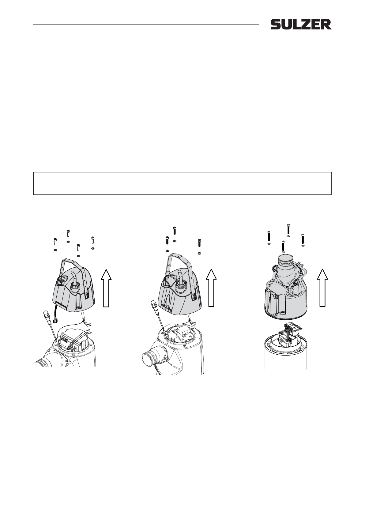
2.3 Dismantling cover
Unscrew and lift o the cover and disconnect the power cables from the contactor/terminal block.
If the water has penetrated through the cable gland and the cable seal, the cable gland and the cable seal should be replaced. Remove strain relief clamp prior to unscrewing cable gland body. Pull out cable, cable gland, washer and unscrew
the cable seal.
DANGER! Always check that the pump is disconnected from the electric power supply
c
before opening any part of the pump.
Standard versionAquaTronic version XJC
7
Page 8
Workshop manual
XJ 25 - 110, XJC 50 - 110, XJS 25 - 110
2.4 Insulation test
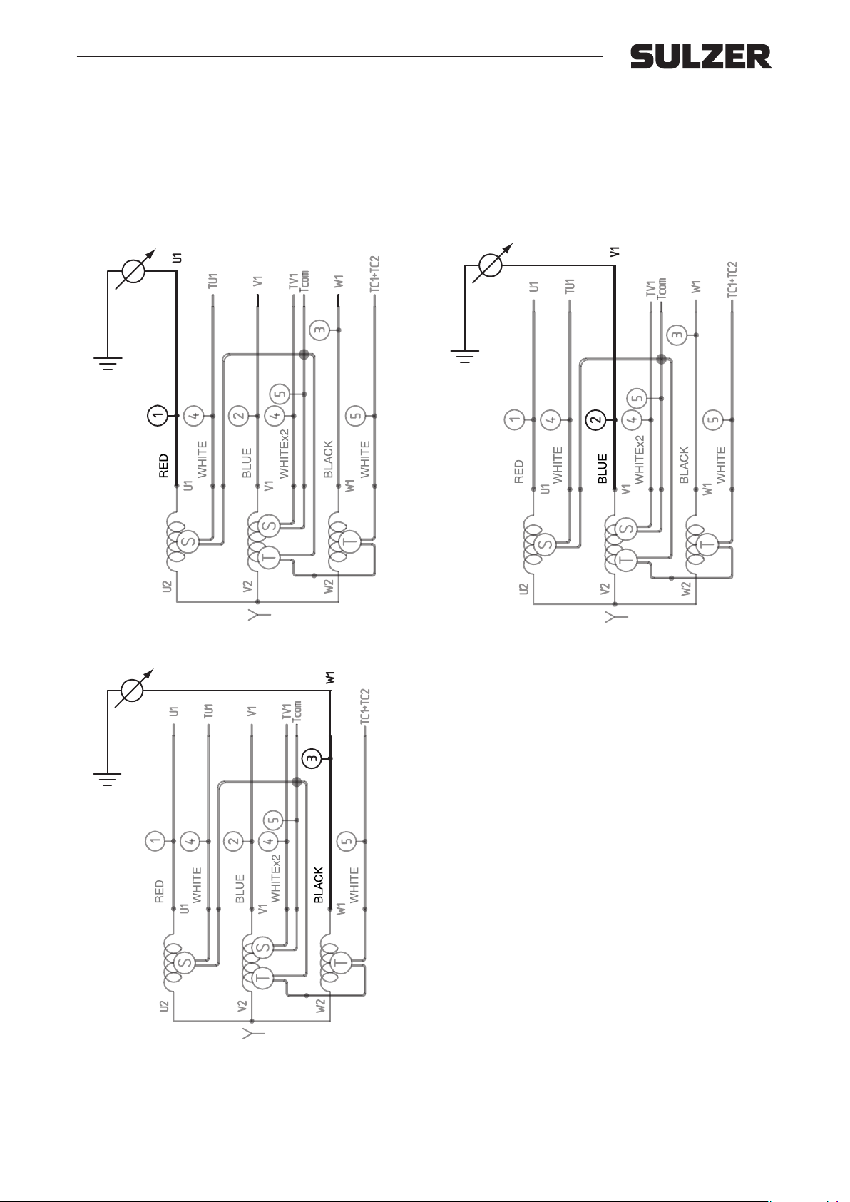
Disconnect stator leads. Check that the contact points are not burned. Measure insulation resistance between the dierent
phase windings, between windings and earth and between windings and thermal sensor circuit.
The insulation resistance should be measured with 500 V megohmeter (megger) and the reading should be at least 1 MΩ.
If the insulation resistance is lower, the stator unit should be dried in an oven. If the stator insulation reading after drying is
still low, the stator unit should be replaced. See chapter 7.
The insulation between the separate turns in the winding should also be checked. This can be done by measuring the
resistance of the phase windings, which should give the same reading for all three windings for 3-phase motors. For resistance values and wiring diagrams check chapter 9.
8
Page 9
Workshop manual
XJ 25 - 110, XJC 50 - 110, XJS 25 - 110
2.5 Thermal sensors
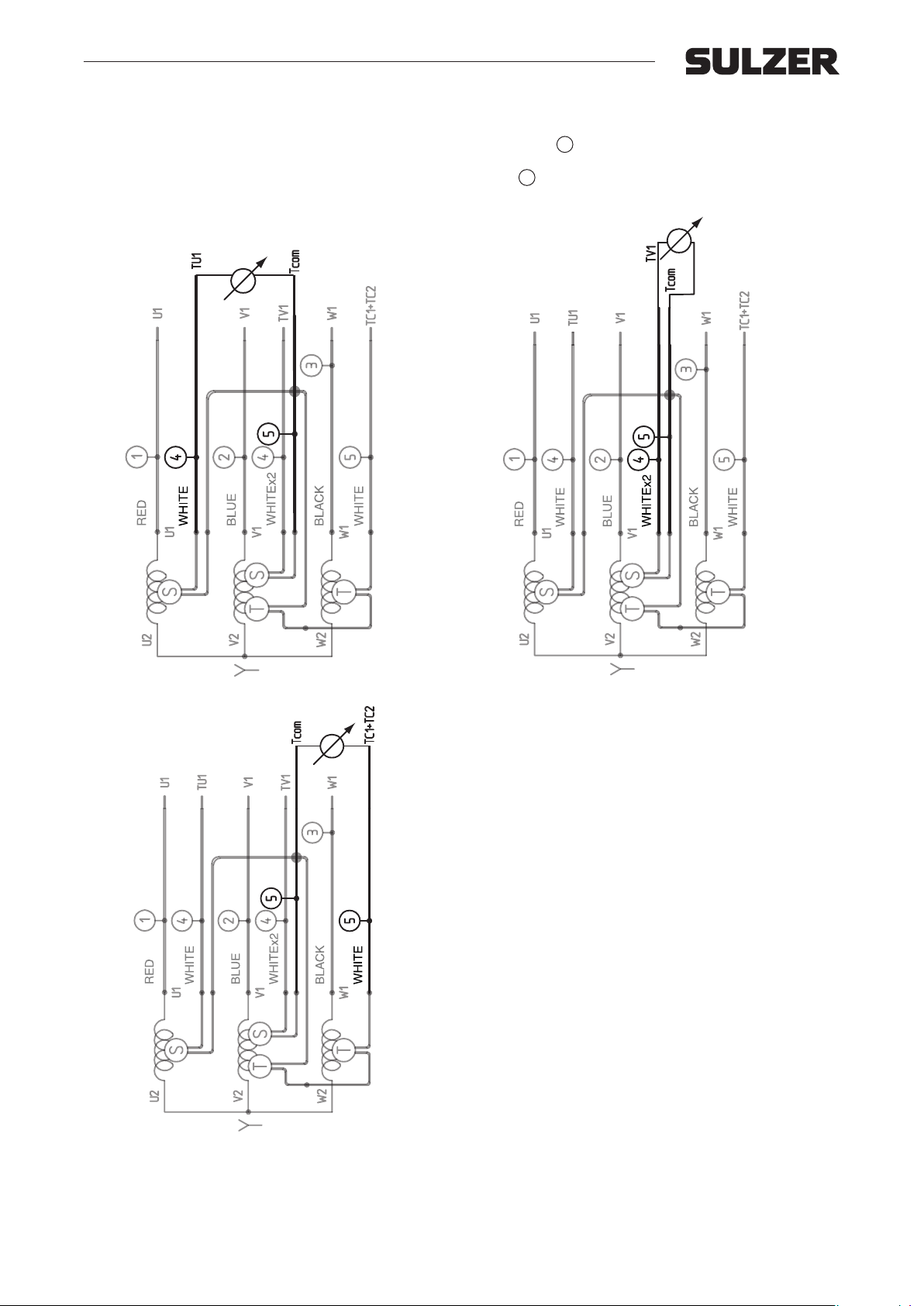
The circuit thermal sensors with the two built-in NTC thermistors (TU1+TV1) S , used when pumps are equipped with
AquaTronic, should be checked for continuity, using an ohmmeter. At 25ºC = 47 kOhm. The circuit, used when pumps are
equipped with DS contactor, with the two thermal contacts (TC1+TC2) T should be checked for continuity, using an ohm-
meter or buzzer.
If one sensor has much too high or low resistance it should be removed from terminals at AquaTronic module.
9
Page 10
Workshop manual
XJ 25 - 110, XJC 50 - 110, XJS 25 - 110
3. Oil / Motor check
3.1 AquaTronic version
See separate manual for Service Diagnostic Program.
3.2 Standard version and AquaTronic version
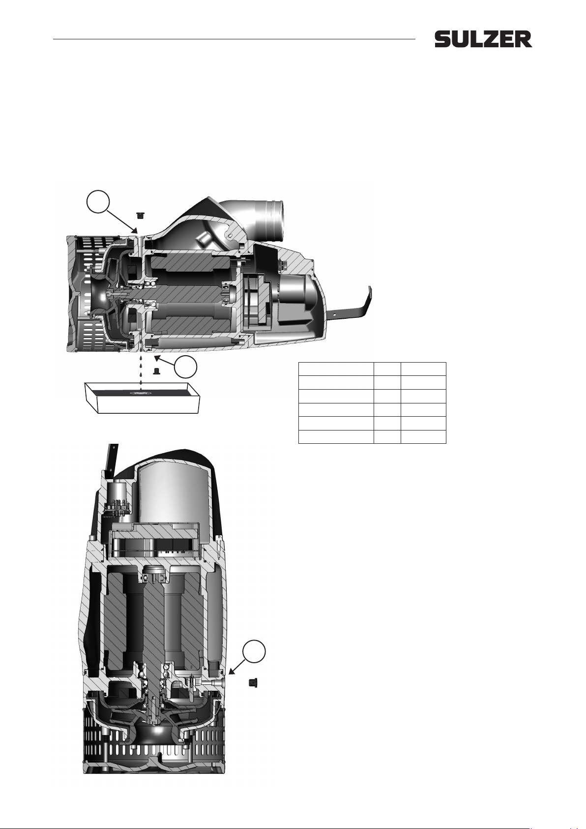
Unscrew the two oil plugs and drain o the oil in a clean can and inspect it. Oil should be clear and without impurity.
For relling of oil see chapter 8.9.
OIL
OIL
Models litres US gallon
XJ/XJS 25 0.4 0.11
XJ/XJS 40 0.4 0.11
XJ/XJC/XJS 50 0.9 0.24
XJ/XJC/XJS 80 0.9 0.24
XJ/XJC/XJS 110 0.9 0.24
M
The motor plug gives access to the motor housing.
Unscrew and check to make sure no oil or water has leaked
into the motor housing.
10
Page 11
Workshop manual
XJ 25 - 110, XJC 50 - 110, XJS 25 - 110
4. Hydraulic check
If the test run against shut of head shows that the pump is not close to expected head a hydraulic check is needed.
4.1 Wear ring ND, HD
4.1.1 Adjustment of wear ring
CAUTION!
Do not place the pump directly on the AquaTronic unit.
m
It will break.
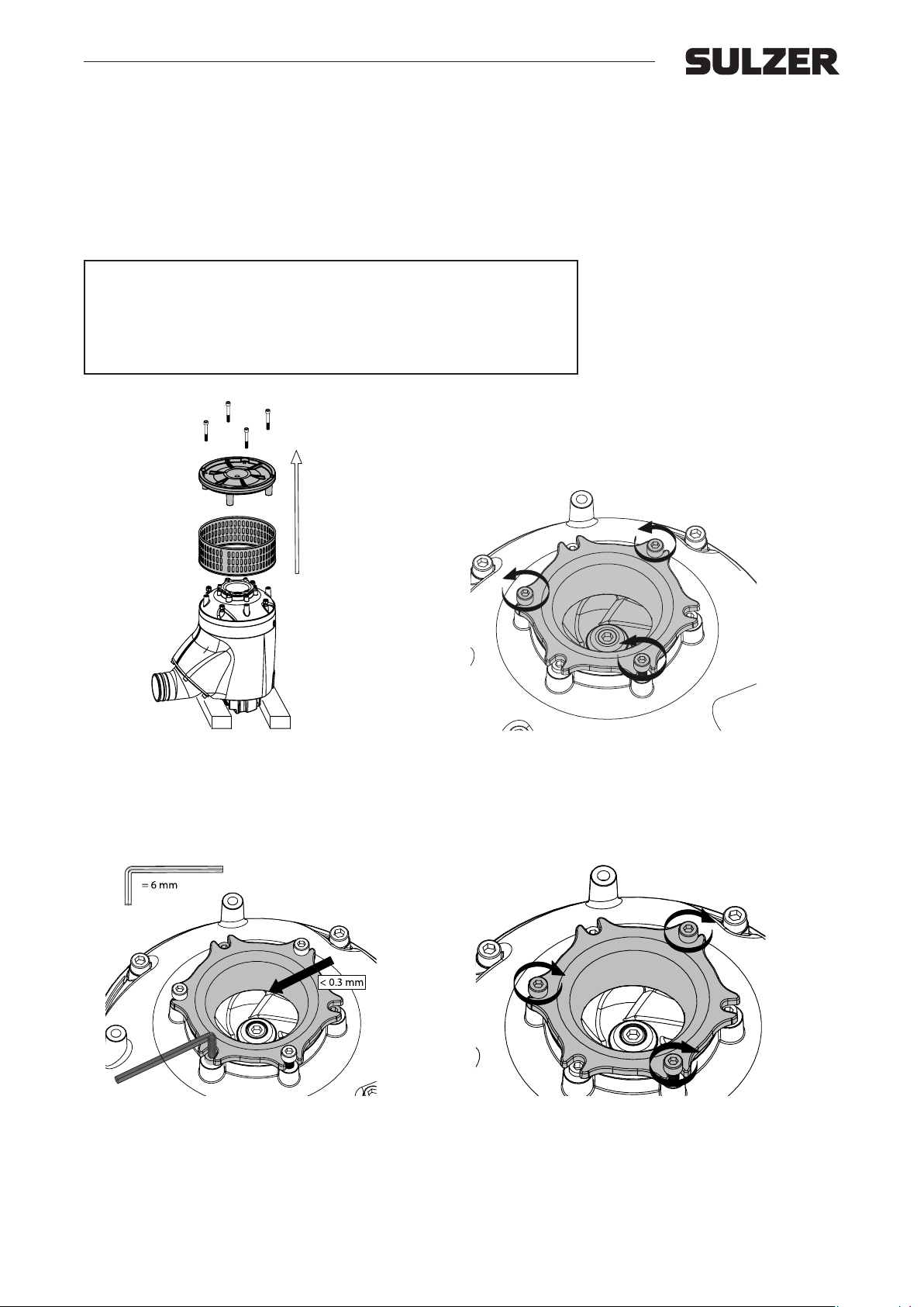
Turn the pump upside down and remove the base plate and
strainer.
Adjust the clearance with the three screws that hold the
wear ring.
Check clearance between wear ring and impeller. Clearance should be less than 0.3 mm. Loosen the wear ring to
make adjustments.
Fasten wear ring with remaining three screws.
11
Page 12
Workshop manual
XJ 25 - 110, XJC 50 - 110, XJS 25 - 110
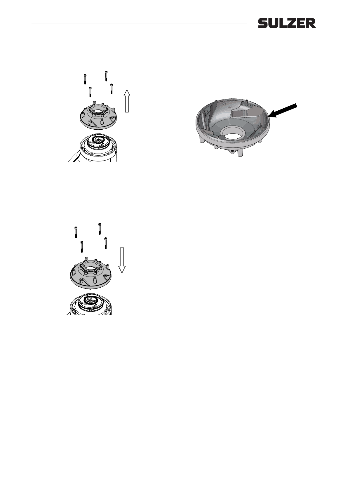
4.2 Diuser ND, HD, LD
4.2.1 Dismantling of diuser
Remove the screws which hold the upper diuser and bear-
ing house together.
4.2.2 Assembly of diuser.
Fasten the upper diuser on the bearing house.
Check the diuser for scratches. The rubber should have a
smooth surface.
12
Page 13
Workshop manual
XJ 25 - 110, XJC 50 - 110, XJS 25 - 110
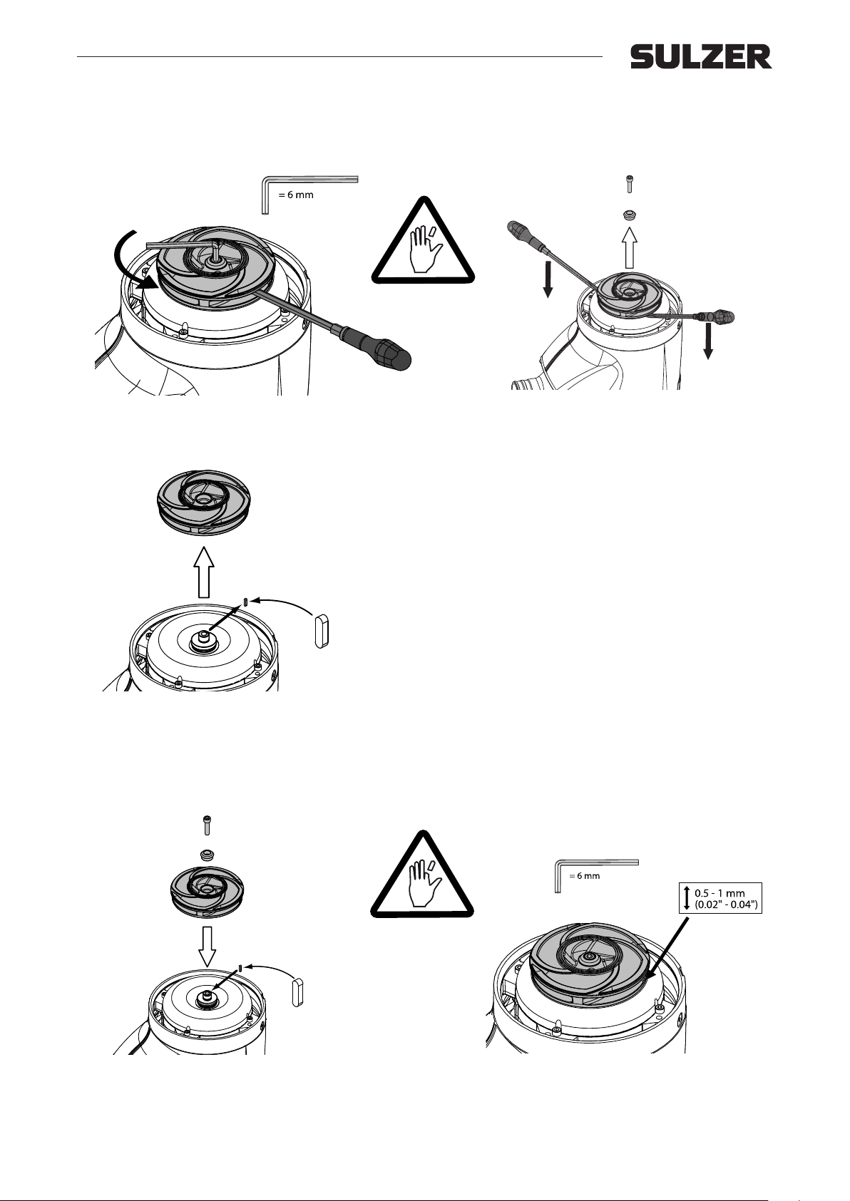
4.3 Impeller ND, HD, LD
4.3.1 Dismantling of impeller
Hold the impeller with a large screwdriver or similar, between the vanes and unscrew the impeller washer.
Remove the key from the shaft.
4.3.2 Assembly of impeller
Pry the impeller loose with two screwdrivers under the im-
peller hub.
Mount the new impeller on the shaft, securing it with key,
washer and screw.
Check that the impeller runs free of upper diuser with a
clearance of 0.5 - 1 mm (0.02 - 0.04”). Adjust the clearance
with shims between impeller and the shaft if necessary.
13
Page 14
Workshop manual
XJ 25 - 110, XJC 50 - 110, XJS 25 - 110
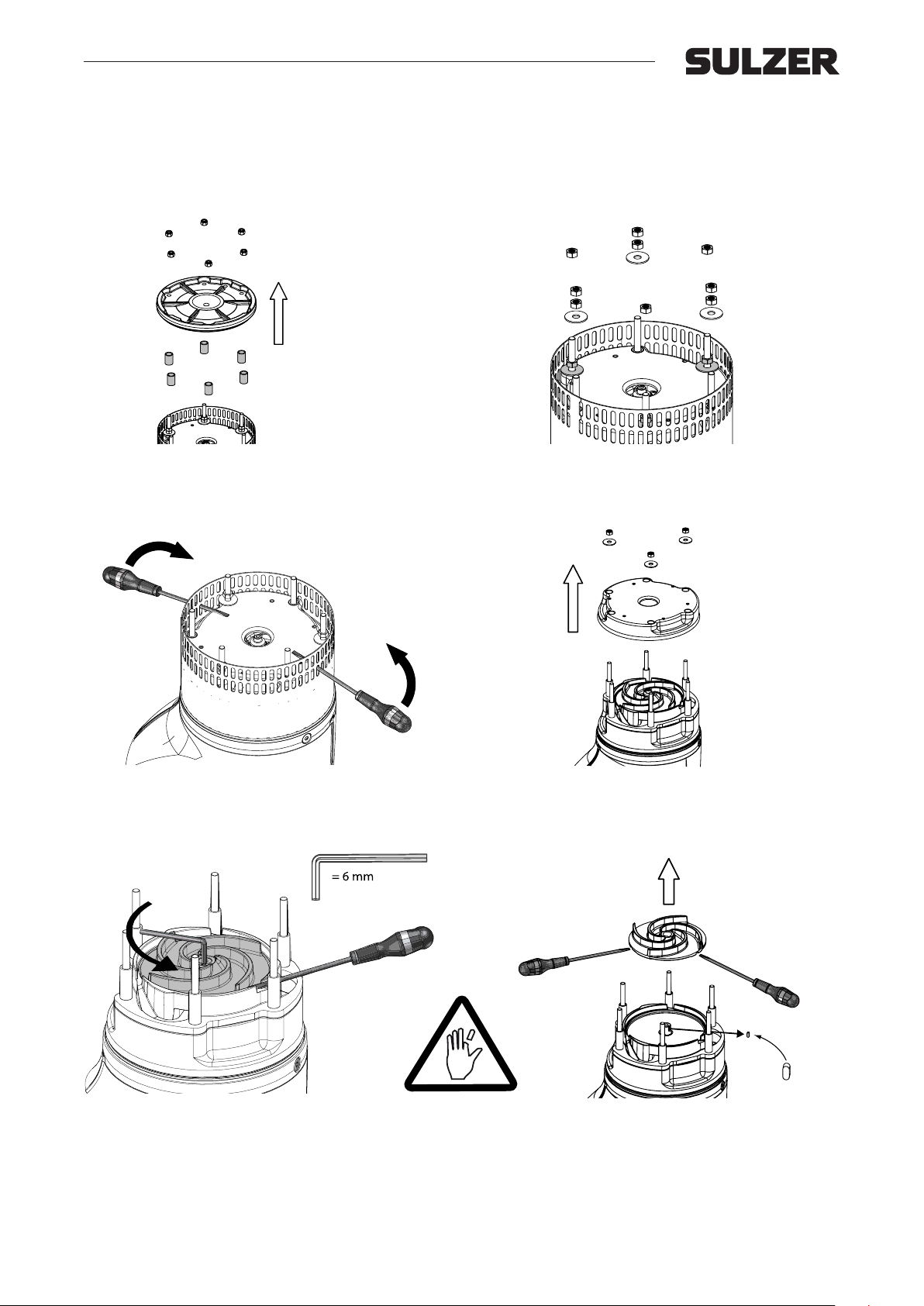
5. XJ 80 SD, change of diusers, impellers and guide vane plate
5.1 Dismantling
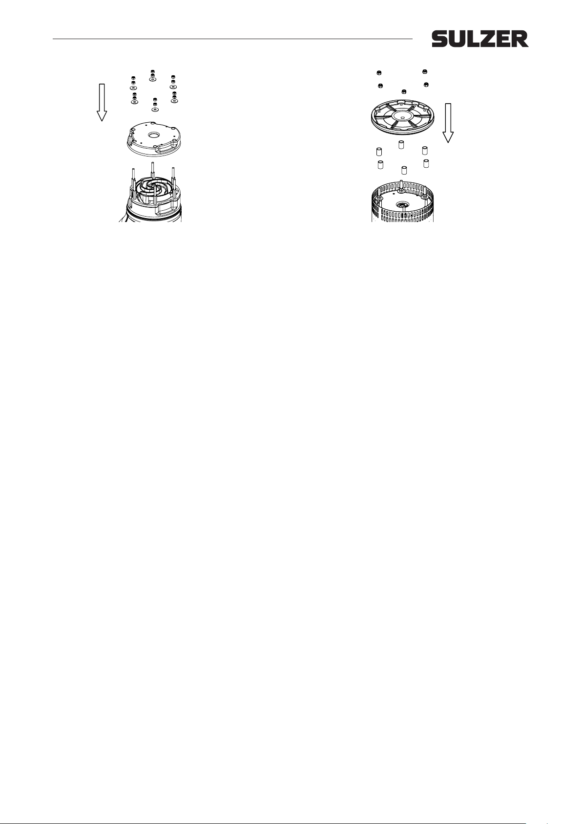
Turn the pump upside down Loosen the bottom nuts and
remove the base plate and the rubber sleeves.
Then loosen the strainer by adding leverage from the diffuser by inserting two screwdrivers in the strainer and press
against the diuser.
Loosen the dual nuts and washers that hold the lower diffuser but make sure to leave three nuts to keep the diuser
in place (loosen them a few turns only).
Remove the remaining three nuts and then the lower dif-
fuser by pulling it gently straight out.
Hold the impeller with a large screwdriver or similar, between the vanes and unscrew the impeller screw with an 6
mm Allen key.
Turn the impeller so the three marks on the impeller side
meet the channels of the guide vane plate. Pry the lower
impeller loose with screwdrivers on the marks of the impeller sides. Remove the key from the shaft. If the impeller
is stuck, hit it carefully in circles with a hammer and use a
creeping lubricant if needed.
14
Page 15
Workshop manual
XJ 25 - 110, XJC 50 - 110, XJS 25 - 110
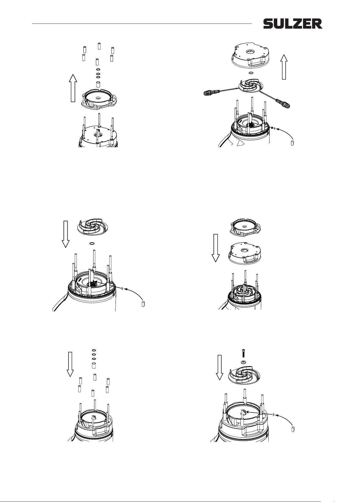
Remove the distance sleeve between the impellers and
pull out the guide vane plate. Note the number of 0.5 shims
on top of the distance sleeve before removing them, also
check for shims under the distance sleeve and or top of the
lower impeller.
5.2 Assembly
Put the shims on the shaft, then the upper key in place on
the shaft and mount the new upper impeller. Check that the
impeller runs free of wear plate. Adjust the clearance with
shims between impeller and shaft if necessary.
Pull out the upper diuser. Turn the impeller so the three
marks on the impeller side meet the channels of the wear
plate. Pry the upper impeller loose with screwdrivers on the
marks of the impeller sides. Remove the key from the shaft.
If the impeller is stuck hit it carefully in circles with a ham-
mer. Check if there are shims on top of the upper impeller,
if so remove them too.
Put on the upper diuser and then the guide vane plate on
the stud bolts and push them in place. Check that the distances are in place in the diuser.
Place the shims and then the tube distance between the
impellers on the shaft.
Mount the new lower impeller on the shaft securing it with
the key, spring washer and screw. Check that the impeller runs free of guide vane plate. Adjust the clearance with
shims between the tube distance and upper impeller if nec-
essary.
15
Page 16
Workshop manual
XJ 25 - 110, XJC 50 - 110, XJS 25 - 110
Mount the lower diuser on the stud bolts and screw two
screws onto each stud bolt. Check that the distances are
in place in the diuser.
Grease and mount o-ring on the oil casing. Put the strainer
in place and then the rubber sleeves and the base plate.
Tighten it up with the bottom nuts.
16
Page 17
Workshop manual
XJ 25 - 110, XJC 50 - 110, XJS 25 - 110
6. Primary seal and upper diuser
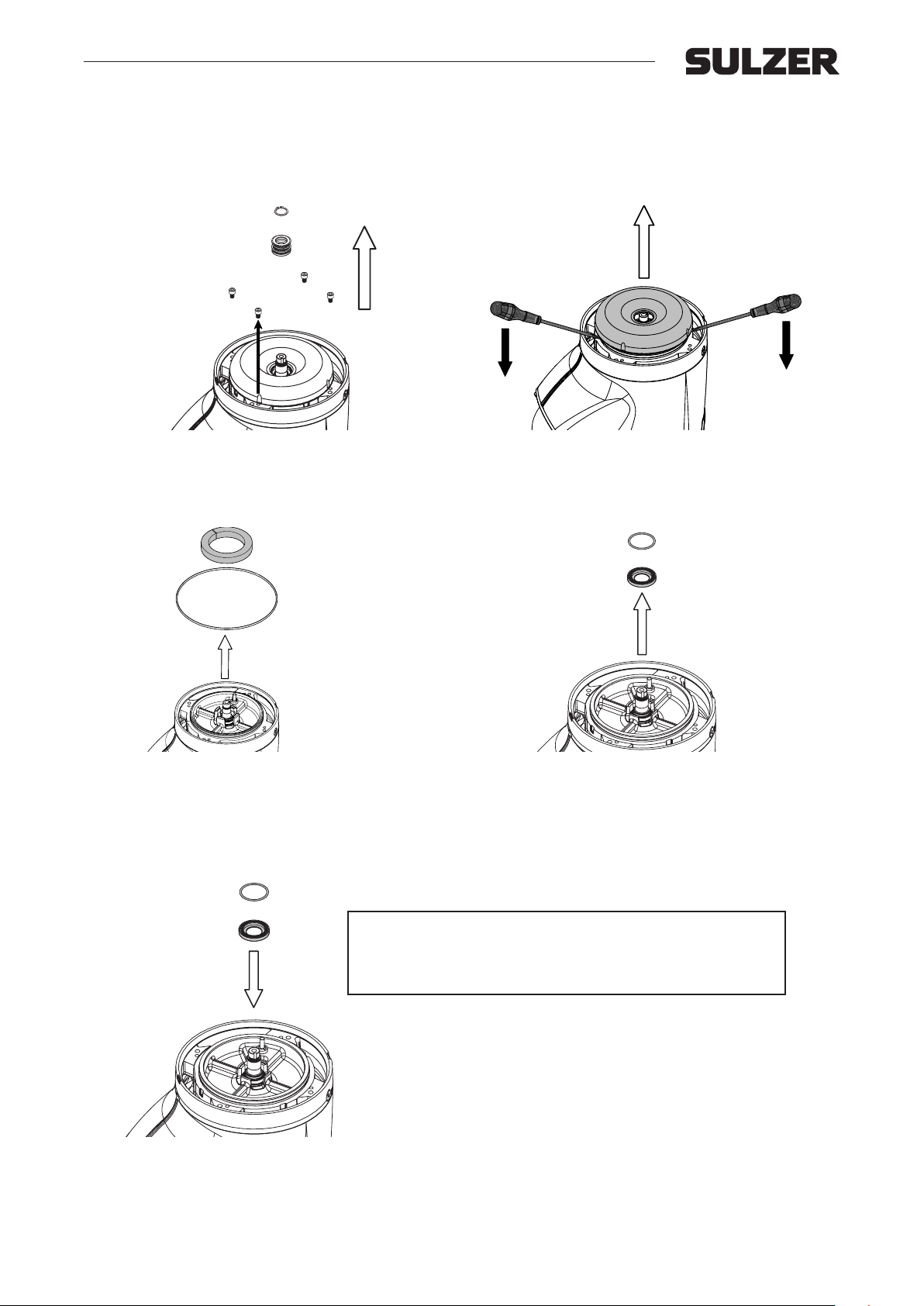
6.1 Dismantling of primary seal and upper diuser
Remove the circlip and pull out the rotating part of the pri-
mary seal. Remove the screws which hold the diuser and
bearing house together.
Remove the rubber foam and o-ring in the bearing house.
Withdraw the upper diuser by using two screwdrivers.
Remove the stationary ring with o-ring, of the
primary seal.
6.2 Assembly of primary seal and upper diuser
Always use new mechanical seals for assembly.
m
Mount stationary ring of primary seal with o-ring in its seat
in the bearing house.
For repair kit part nos see chapter 1.2.
Before the outer o-ring is mounted on the bearing house,
check that upper diuser is compressing the o-ring in the
stationary seal enough to give ecient sealing.
17
Page 18
Workshop manual
XJ 25 - 110, XJC 50 - 110, XJS 25 - 110
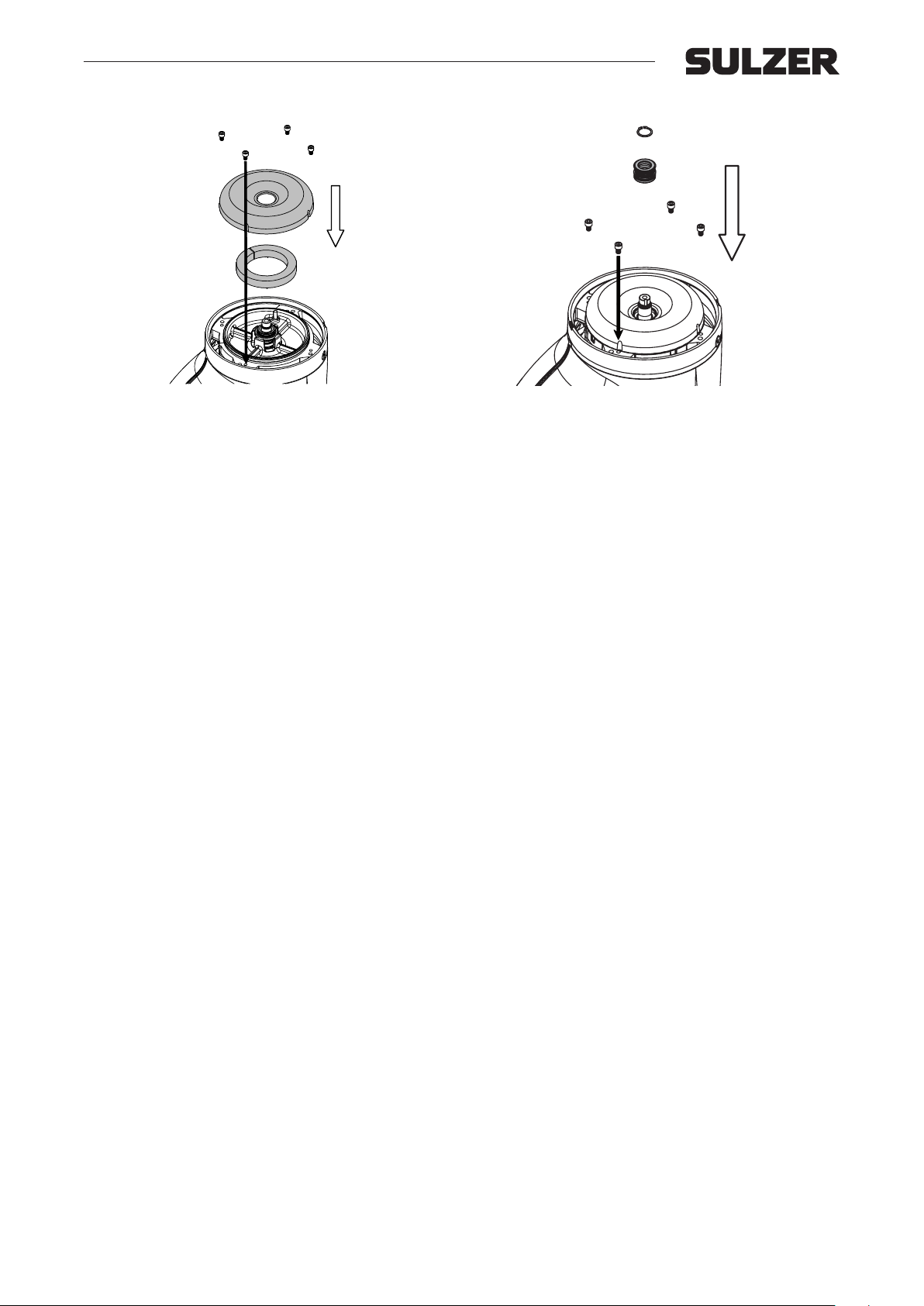
Place the rubber foam in the bearing house. Grease and
mount o-ring on the bearing house, and mount upper diffuser with screws. Tighten gradually crosswise.
Grease and mount a new primary seal o-ring on the shaft.
Oil the sealing surfaces of the mechanical seal and push
the rotating ring onto the shaft
18
Page 19
Workshop manual
XJ 25 - 110, XJC 50 - 110, XJS 25 - 110
7. Complete pump overhaul / dismantling
Perform all dismantling operation in chapter 2 then continue with:.
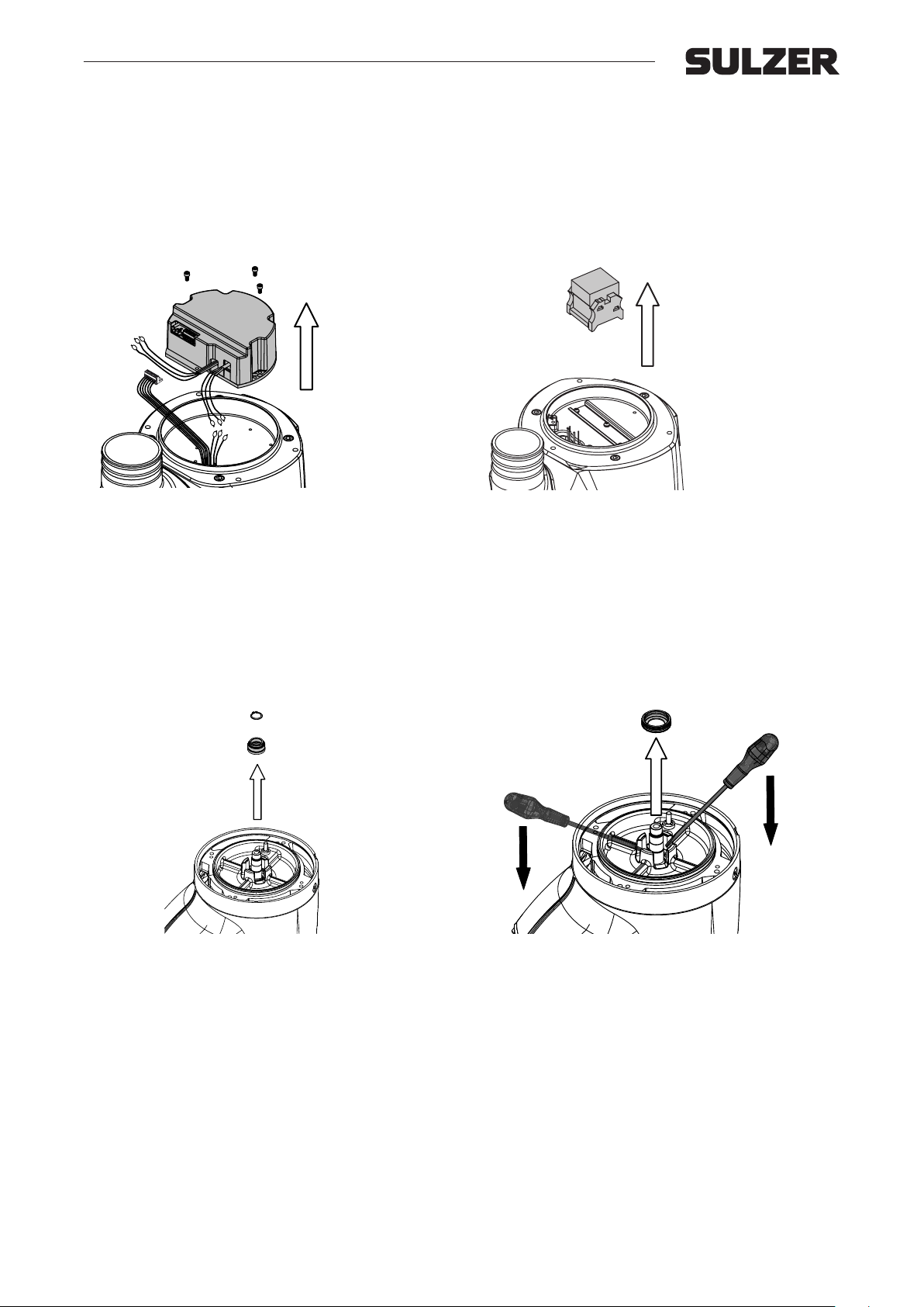
7.1 Electronics
7.1.1 AquaTronic version
Turn the pump and remove AquaTronic
7.1.2 Standard version
Turn the pump and remove the contactor from the omega
rail.
7.2 Oil/motor, hydraulic, primary seal and upper diuser
Perform all dismantling operation in chapter 3-5 then continue with:
7.3 Secondary seal
7.3.1 Dismantling of secondary seal
Remove circlip and rotating parts of secondary seal from
the shaft.
Remove the stationary ring with two screwdrivers.
19
Page 20
Workshop manual
XJ 25 - 110, XJC 50 - 110, XJS 25 - 110
7.4 Rotor unit
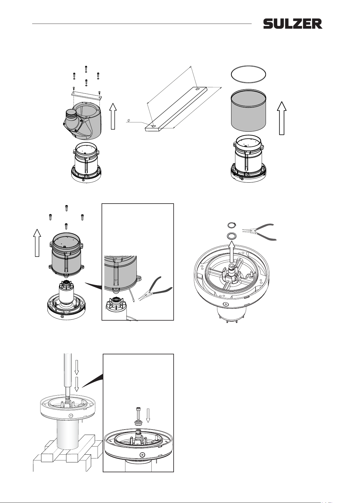
7.4.1 Dismantling of rotor unit.
254
11 (2x)
Lifting tool for XJ 50 - XJ 110.
280
Remove the jacket (for easy dismantling of jacket use lifting
tool).
m On AquaTronic
units, remove leakage
sensor. Be careful not to
damage cable.
Remove the stator and motor housing from the rotor unit.
Remove the jacket on XJC.
Remove the external circlip with a pair of circlip pliers
(diameter 25 mm) and remove washer (holding the bearing).
m If high pressure is
needed, screw the impeller
nut fully on the shaft end in
order to protect it
Place the rotor into a tube or similar of the same length as
the rotor shaft and with an inner diameter slightly larger
then the outer diameter of the bearing seat. Press against
the end of the shaft until the rotor comes loose. The bearing seat can be heated quickly with LP-gas to facilitate the
removal.
20
Page 21
Workshop manual
250
482
˚C˚F
XJ 25 - 110, XJC 50 - 110, XJS 25 - 110
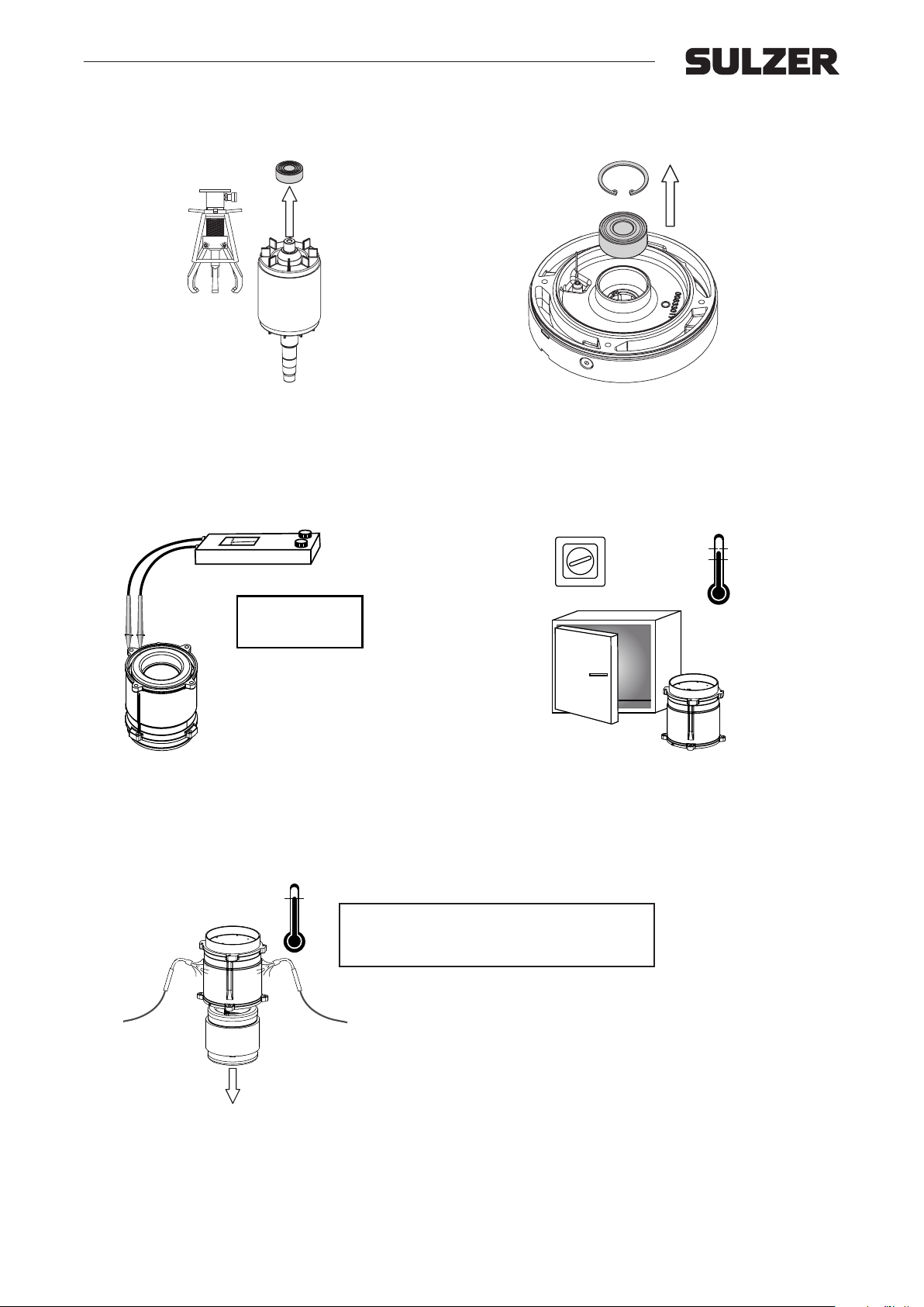
7.5 Dismantling of ball bearings
Remove upper bearing with a ball bearing puller tool.
7.6 Stator
7.6.1 Insulation check
> 1MΩ = OK
< 1MΩ = not OK
Measure the insulation resistance with a 500 V megohmeter (megger). If the insulation resistance is lower than 1
MΩ the stator unit should be dried in an oven.
7.6.2 Dismantling of stator
Remove the circlip and press out the bearing. Make sure to
support the bearing house properly.
1
13
2
12
3
11
4
10
> 2-3 h
5
9
6
8
7
194
176
90
80
˚C˚F
Dry the stator unit in oven in not more than 80-90 °C (176194 °F) for at least 2-3 hours. If the insulation resistance
still is too low the unit should be replaced.
Arrange the motor cables so as to avoid
jamming when the stator is falling out of
the housing.
Heat the motor housing with two LP gas ames (large propane burner) at the stator laminations and downwards until
the temperature of about 250 °C (482 °F) is reached or till
the stator starts to fall out.
Clean the housing and check it for damages. Particularly on
the sealing surfaces and in ball bearing seat. If damages
cannot be corrected, the housing must be replaced.
21
Page 22
Workshop manual
XJ 25 - 110, XJC 50 - 110, XJS 25 - 110
8. Complete pump overhaul / assembly
8.1 General
Clean all parts carefully, especially o-ring groves and mating surfaces.
Grease or oil o-rings to eliminate damage during assembly. Grease or oil screw threads to simplify disassembly during
future overhaul.
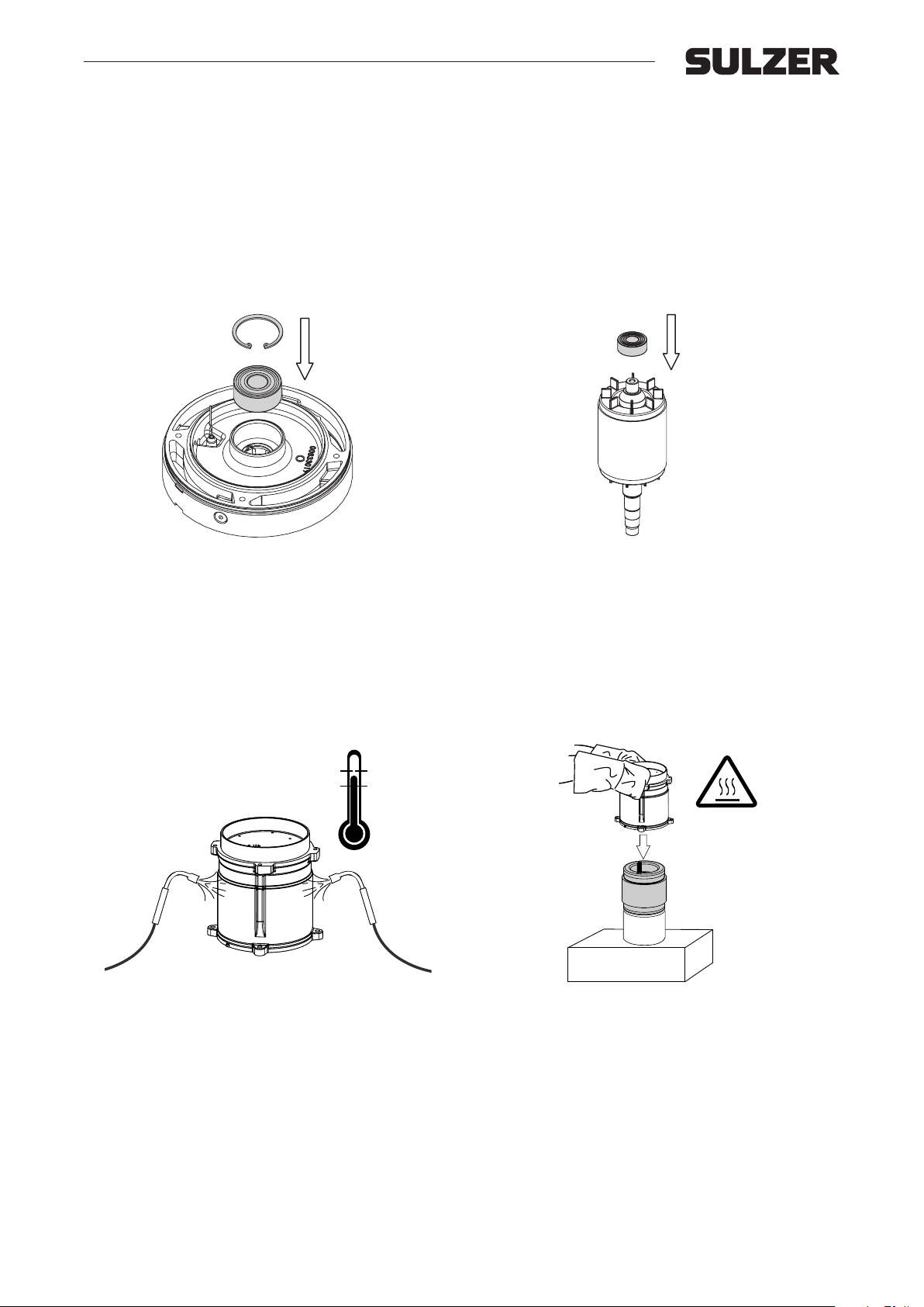
8.2 Assembly of ball bearings
Clean the bearing house and all sealing surfaces thoroughly. Remove burrs and scratches. All ball bearings are
sealed and pre-lled with grease for lifetime performance.
Heat the bearing seat with LP-gas to about 150ºC (302ºF)
and mount the bearing in the seat. Mount the cirlip on top of
the bearing.
8.3 Assembly of stator
˚C˚F
482
388
Heat the housing with two LP-gas ames to about 198 °C
to 250 °C (388 °F to 482 °F).
Protect the stator insulation from damages and put down
the thermal wires (free from insulation resin and smooth)
into the stator to avoid contact with the hot housing during
assembly.
250
198
Press upper bearing into position against the shaft shoulders. Use properly sized press tool.
Take the hot housing with heat-resistant gloves and push
it down till it stops over the stator, or the other way around,
drop the stator into the housing.
Note! Locate the holes for the thermal cables in the hous-
ing about 10 mm from the exit of the cable groups on the
winding head.
22
Page 23
Workshop manual
XJ 25 - 110, XJC 50 - 110, XJS 25 - 110
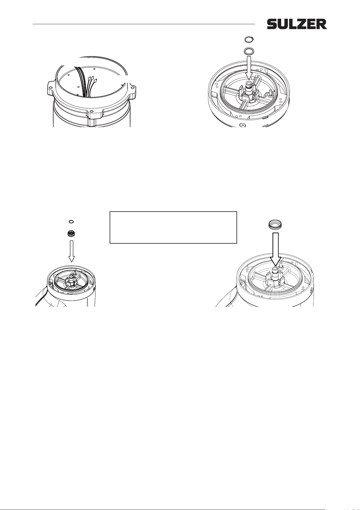
Sensor cables
Motor cables
When the housing has been mounted it may be cooled by
compressed air. When the housing has cooled down the
terminal cables can be pulled up through the holes in the
housing with a hook.
8.4 Secondary seal
Always use new mechanical
m
seals for assembly.
For repair kit part nos see
chapter 1.2.
Press rotor with shaft in place in the bearing house (with
the bearing assembled) assemble the washer and the
circlip. Make sure to support bearing properly.
Turn the rotor by hand and check that it turns freely without
seizing. Grease and mount o-ring on the casing. Slip the
rotor unit into the stator unit and check that the o-ring is not
jammed.
Clean and grease the seal seat in the bearing house and
mount the stationary ring with o-ring. Push it down to the
bottom of the seat.
Push the rotating part of the secondary seal onto the shaft.
Mount the circlip and push it down till it ts into the grove.
8.5 Primary seal and upper diuser
For assembly of primary seal and upper diuser see section 5.2.
8.6 Impeller
For assembly of impeller see section 4.3.2
8.7 Assembly of diuser
For assembly of diuser see section 4.2.2.
8.8 Base plate and strainer
8.8.1 With distances
Place the distances and the strainer in position before tightening the base plate bolts.
8.8.2 Without distances
Put strainer and baseplate in place and tighten bolts.
23
Page 24
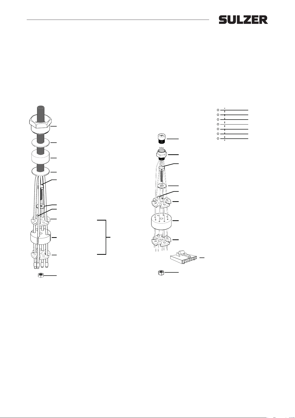
Workshop manual
washer
cable gland
washer
tap
plastic washer
plastic washer
cable seal
bushing
cable seal
screw
washer
nut
XJ 25 - 110, XJC 50 - 110, XJS 25 - 110
8.9 Relling of oil
Fill all the way up to entrance of oil inspection hole. Make sure to ll in oil chamber marked with an oil drop. Tighten the oil
plug with a new o-ring
Use Paran oil (white oil) with viscosity 10-15 cSt, e.g. BP Enerpar M 002 or equivalent.
For oil quantity see chap. 3.2.
8.10 Change of cable gland
8.10.1 Change of cable gland 8.10.2 Change of AquaTronic connection interface
Wiring diagram
white1
2
3
4
5
6
cap
7
AquaTronic connection
brown
green
yellow
grey
pink
blue
Measure inner diameter of cable bushing to see that it corresponds to the cable diameter. Place cable bushing and
washers (one on each side) on the cable.
Pull cable through the cover, far enough to let the cable
gland seat on a non-deformed portion of cable. Make sure
that the non stripped cable is going all the way through the
bushing.
Tighten the cable gland and strain relief clamp on the handle. Put the plastic washer (one on each side) and cable
seal in place. Make sure that the plastic tap ts the hole in
the cable seal.
Push the cable seal in place in the top cover and tighten the
screw. Make sure that the washer is in place.
Connect the phases according the wiring diagram (chapter
9.1). Yellow/green earth screwed to cover.
screw
washer
tap
plastic washer
cable seal
plastic washer
7 pole connector
nut
Cut or disassemble the 7-pole connector from the cable
terminals. Unscrew and remove all cable seal parts and
connectors.
Replace connector and make sure that the o-ring seat is
okay.
Put all cable seal parts together and x the cable seal in
the top cover by tightening the screw. Make sure that the
washer is in place and the tap ts the hole in the cable
seal.
Assemble the cable cores with the 7-pole connector. Note
the wiring.
24
Page 25

Workshop manual
XJ 25 - 110, XJC 50 - 110, XJS 25 - 110
8.11 Assemble the top cover
Grease and mount the o-ring on the cover. Mount the cover on the jacket and arrange the leads so that they may not be
jammed or block the functioning of the contactor. Tighten cover with the screws.
9. Testing
Connect motor cable to power supply and start the pump. If possible, operate the pump in water and measure the head
against closed valve. Also make sure that the rotor is rotating in correct direction if the stator is changed/repaired or the AT
is changed.
With AT connect the AquaTronic USB interface cable (00863329) and make sure that a correct connection is established
by opening Aquatron.exe software from the AT directory.
25
Page 26
Workshop manual
W1
V11U1
U1
V1
W1
00833286AA
V5U5W5
U1W1V1
1
5
230V Y parallel
460V Y serie
V5
V1
U1
W5
W1
1
5
U5
00833287AA
XJ 25 - 110, XJC 50 - 110, XJS 25 - 110
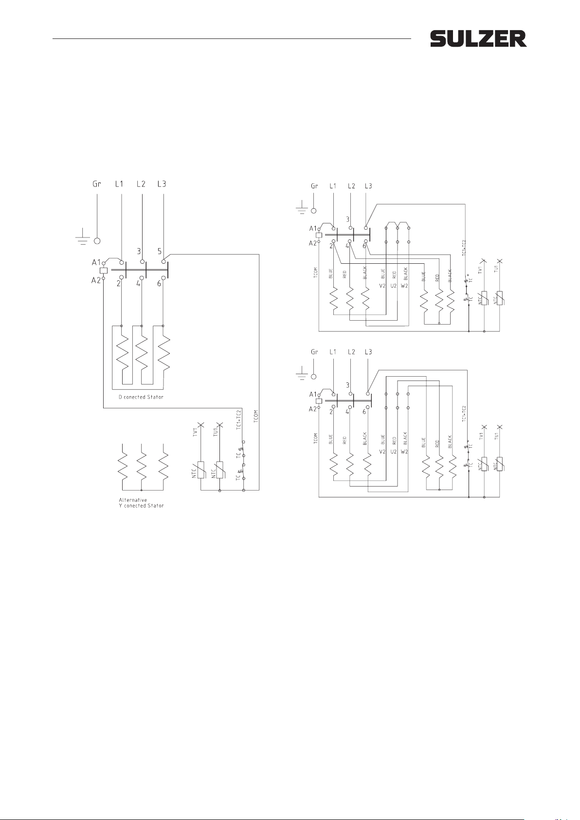
10. Electrical information and wiring diagrams
10.1 Three phase Direct Start D.O.L. with contactor
The stators are wound for dierent voltages and can be internally Delta- or Star-connected.
The contactor is activated by the same voltage as the supply voltage. Therefore, when changing from one voltage to another the contactor must also be changed.
Figure 1: Direct start with contactor.
Figure 2: Direct start with contactor 230/460 V.
26
Page 27
Workshop manual
00833234AC
(XJ 25)
(XJ 25-40)
(XJ 25-50)
(XJ 25-80)
00833285AA
(XJ 40)
XJ 25 - 110, XJC 50 - 110, XJS 25 - 110
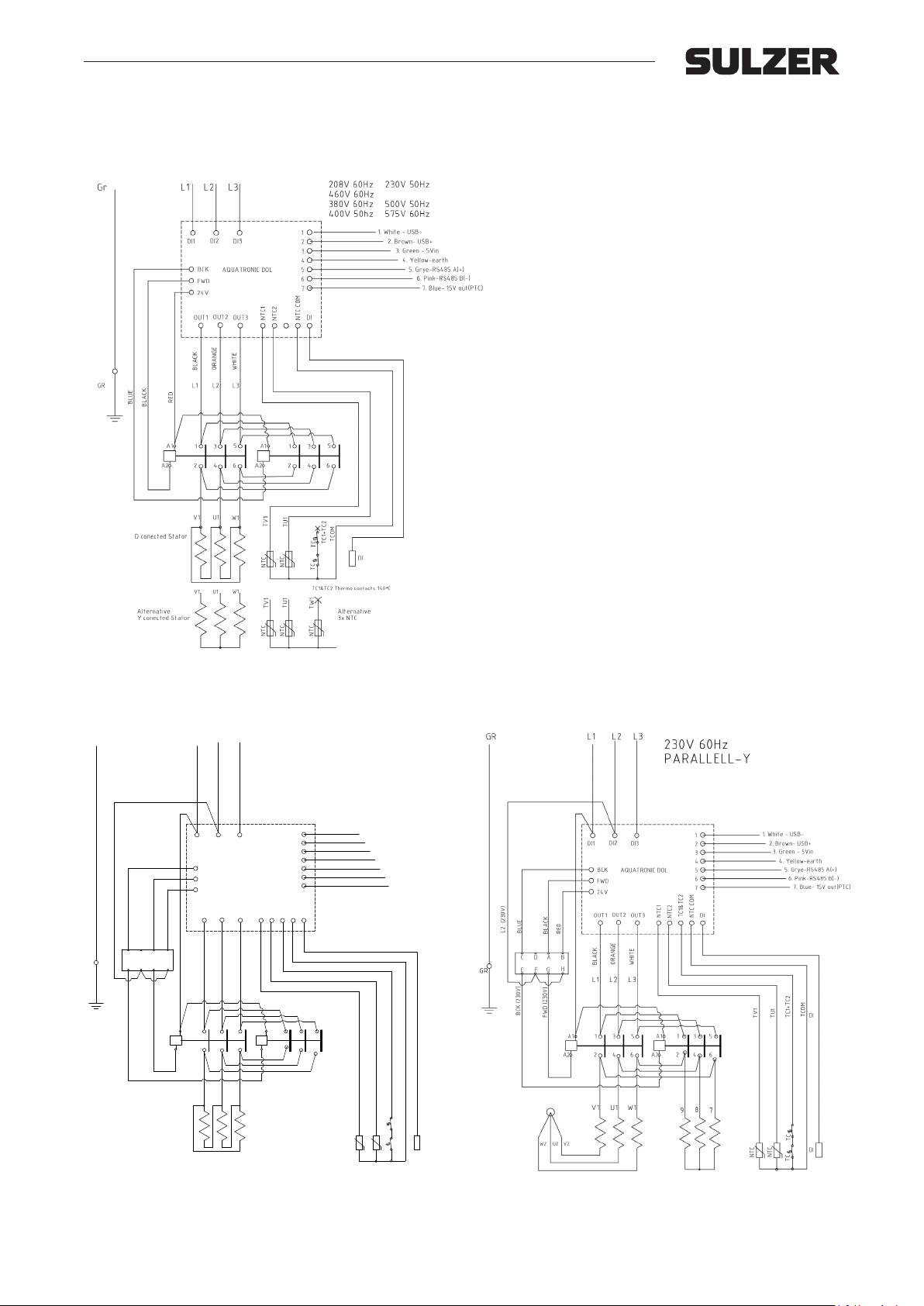
10.2 Three phase Direct Start D.O.L. with AquaTronic
The stators are wound for dierent voltages and can be internally Delta- or Star-connected.
Figure 3: Direct start with AquaTronic.
GR
L2 (230V)
BLUE
C
F G
E
GR
BCK (230V)
L1 L2
L3
230V 50Hz (XJ 40)
NTC1
A1A1
A2A2
1
2
3
4
5
6
7
TC1&TC2
DI
NTC COM
NTC2
1
DI2
DI1
DI3
BCK
AQUATRONIC DOL
FWD
24V
OUT2
OUT1
OUT3
RED
BLACK
A BD
H
FWD (230V)
ORANGE
WHITE
BLACK
L2L1
L3
5
3
1
4
2
6
U1
W1
V1
1. White - USB-
2. Brown- USB+
3. Green - 5Vin
4. Yellow-earth
5. Grye-RS485 A(+)
6. Pink-RS485 B(-)
7. Blue- 15V out(PTC)
TCOM
TC1+TC2
DI
TU1
TV1
65342
TC
DI
NTC
NTC
TC
00833372AA
Figure 4: Direct start with AquaTronic 230 V 50 Hz, XJ 40.
Figure 5: Direct start with AquaTronic 230 V 50/60 Hz, XJ 40.
27
Page 28
Workshop manual
6
5
4
3
2
1
U1
230V 50/60Hz
380V60Hz
400V 50hz
460V 60Hz
W1
V1
U1V1W1
00833235AC
XJ 25 - 110, XJC 50 - 110, XJS 25 - 110
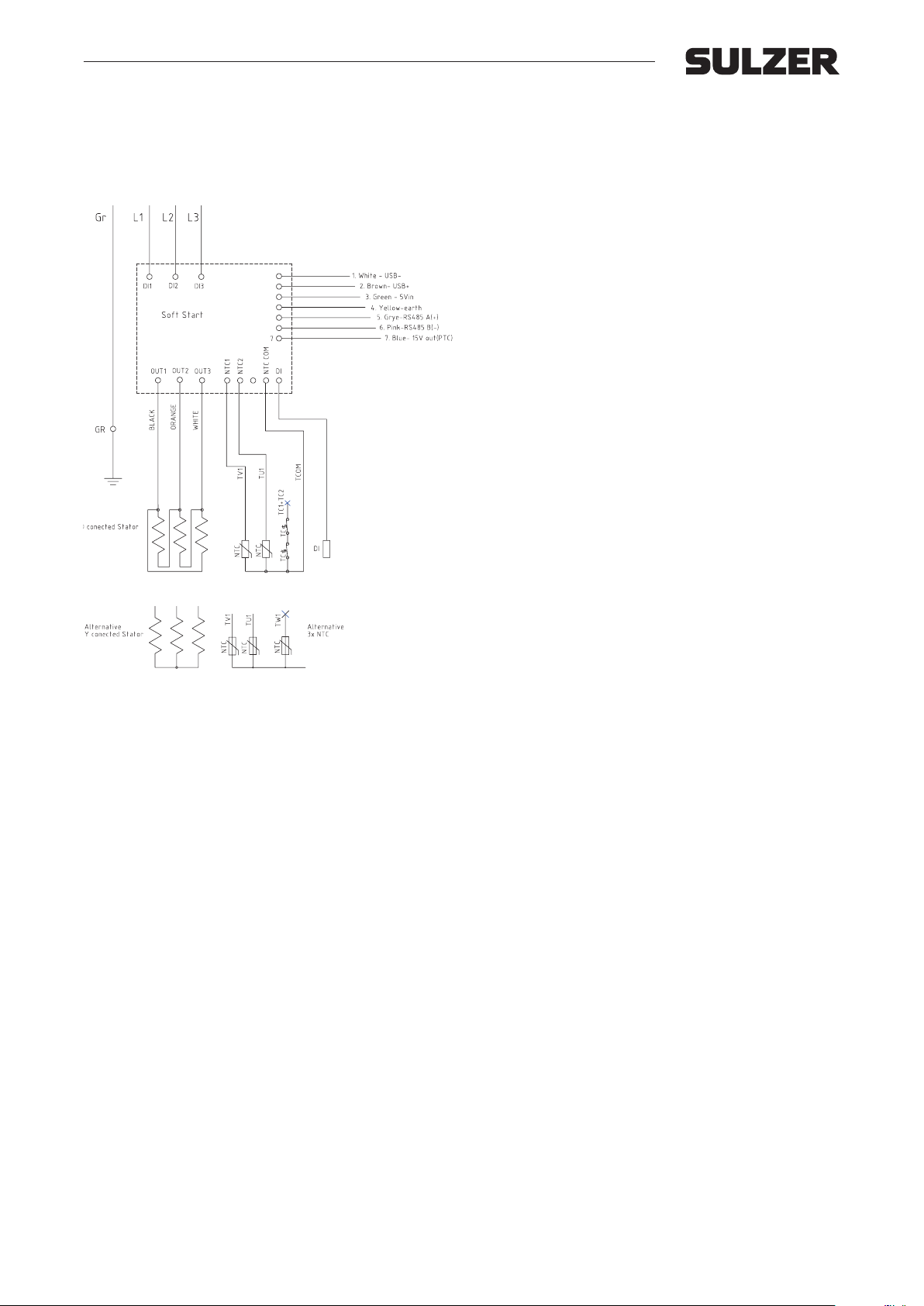
10.3 Three phase Soft Start with AquaTronic.
The stators are wound for dierent voltages and can be internally Delta- or Star-connected.
Figure 6: Soft Start with AquaTronic.
28
Page 29
Workshop manual
00833591AA
1
TERMINAL BOARD
DI
DI
F0
TC
TC
NTC
NTC
V5 U5 W5
BLACK
RED
BLUE
4
U2 W2V2
U1W1V1
RED
BLACK
BLUE
BLACK
RED
BLUE
TCOM
TC1+T C2
Gr
2
3
L1 L2
6
5
L3
230V Y parallel
460V Y serie
V5
V1
BLUE
2
TU1
U2
TC
BLUE
6
TC1+TC2
U1
3
NTC
TV1
RED
BLACK
L3
W5W2
L2
TC
RED
W1
BLACK
TCOM
1
4
5
BLACK
BLUE
U5V2
NTC
L1
RED
Gr
TU1
TV1
TERMINAL BOARD
DI
5
DI
F1F0
F1
RED
BROWN
YELLOW
GREY (GREEN)
BLACK
BLUE
Green/
Yellow
TERMINAL BOARD
MOTOR
THERMAL PROTECTION
1F02 3 4 5 6
F1
L1 L2 L3
F0 F1
U1 V1 W1
U2 W2 V2
357278AA
358387 AB
TERMINAL BOARD
MOTOR
THERMAL PROTECTION
L1
1
F1
2
3
Diode
GC
L2
F0
L3
U1 V1 W1 U2 W2 V2
XJ 25 - 110, XJC 50 - 110, XJS 25 - 110
10.4 Three phase Direct Start D.O.L. with terminal block
The stators are wound for 230 V or 460 V 50 Hz and connected Star. (Figure 7).The stators are wound for 1000 V 50 Hz
and connected Star. (Figure 8). When ground check diode is used see gure 9.
Figure 7: Standard connecting for Direct Start D.O.L
230 V or 400 V 50 Hz.
Figure 8: Standard connecting for Direct Start D.O.L
1000 V 50 Hz.
Figure 9: Optional: Connecting for Direct Start D.O.L
1000 V 50Hz with ground check diode.
29
Page 30
Workshop manual
NTC
Thermal Contacts
XJ / XJS 25
x2 x2
F ∆ Series Clockwise 0,8 38 0,85+0,90 3
x2
F ∆ Series Clockwise 1,15 46 2x0,80 3
x2
F Y Series Clockwise 2,15 37/36 2x0,90 3
x2
F Y Series Clockwise 3,4 46 2x0,80 3
x2
F YY Clockwise 0,85/3,4 46 2x0,80 9
x2
F Y Series Clockwise 5,4 58/57 2x0,71 3
x3
F Y Series Clockwise 9,875 79 0,60+0,63 3
2,5 1000 DOL 00833123 00863123
- x3
F Y Series Clockwise 10,8 115 0,71 6
x2 x2
F ∆ Series Clockwise 0,65 33 0,75+2x0,80 3
x2
F ∆ Series Clockwise 0,95 40 3x0,71 3
x2
F Y Series Clockwise 1,8 32 3x0,80 3
x2
F Y Series Clockwise 2,8 40 3x0,71 3
x2
F YY Clockwise 0,7/2,8 40 3x0,71 9
x2
F Y Series Clockwise 4,4 50 0,75+0,80 3
x3
F Y Series Clockwise 8,382 69 0,65+0,67 6
3,7 1000 DOL
- x3
Y Series Clockwise 8 ,8 100 2x0,55 6
x2 x2
F ∆ Parallel Clockwise 0,3 34 3X0,75 3
x2
F ∆ Parallel Clockwise 0,42 41 2x0,85 3
x2
F ∆ Parallel Clockwise 0,85 57 2x0,71 3
x2
F ∆ Parallel Clockwise 1,3 72 0,9 3
x2
F YY Clockwise 0,33/1,3 21 0,8+3x0,85 9
x2
F ∆ Series Clockwise 2,1 45 2x0,80 3
x3
F Y Parallel Clockwise 3,7 72 0 ,9 6
5,6 1000 DOL
- x3
Y Series Clockwise 4 ,1 52 2x0,75 6
XJ / XJS 80
x2 x2
F ∆ Parallel Clockwise 0,21 28 0,80+2X0,85 3
x2
F ∆ Parallel Clockwise 0,3 34 0,75+2X0,80 3
x2
F ∆ Parallel Clockwise 0,57 47 2x0,80 3
x2
F ∆ Parallel Clockwise 0,9 59 2x0,71 3
x2
F YY Clockwise 0,23/0,9 17 4x0,75+2x0,80 9
x2
F ∆ Parallel Clockwise 1,45 74 2X0,63 3
x3
F Y Parallel Clockwise 2,6 59 2//0,71 6
8,3 1000 DOL
- x3
Y Parallel Clockwise 2,72 85 0,85 6
XJ / XJS 110
x3
H ∆/Y Parallel Clockwise 0,25 24 4x0,80 6
x2
H ∆ Parallel Clockwise 0,17 20 3x0,85+0,90 3
x2
H ∆ Parallel Clockwise 0,74 41 2x0,85 3
x3
H YY Clockwise 0,255/1,02 24 4x0,80 9
x2
H ∆ Parallel Clockwise 1,14 51 2x0,75 3
x3
H Y Parallel Clockwise 1,5 41 2x0,85 6
11,8 578/1000 DOL
- x3
Y Parallel Clockwise 3,1 59 2x0,71 6
P/n
Class
Delta
Rotation
Parallel
slots
hright (mm)
slot
Pitch
wire
TI-523
Temp
(mm)
(mm)
leads
XJ 25 - 110, XJC 50 - 110, XJS 25 - 110
10.5 Winding data
Inner
Outer
Ω
diameter
diameter
Core
No. of
Power
Copper
Turns per
110
90 200 110
24 90 152 80
24 120 152 80
36
1/18-16-14
110 200 110
36
36 170 200
1/18-16-14
Series or
Star or
151007 NH
1
Sheet Date Drawn Checked Approved
Thermik S06.140°C
x2
B57164K473J
-
x2
x2
x2
x2
x2
x2
F
-
x2
x2
x2
x2
x2
F
-
x2
x2
x2
x2
x2
F
-
x2
x2
-
x2
x2
H
-
-
x2
x2
Dwg.-No
00863500 AC
00833124 00863124
DOL = direct
2,9 230 DOL 00833118 00863118
2,9 380 DOL 00833120 00863120
2,9 230/460 DOL 00833295 00863295
4,3 230 DOL
4,3 380 DOL 00833126 00863126
4,3 230/460 DOL 00833296 00863296
00833129 00863129
00833130 00863130
6,7 230 DOL
6,7 380 DOL 00833132 00863132
6,7 230/460 DOL 00833297 00863297
00833135 00863135
9,8 230 DOL 00833136 00863136
9,8 380 DOL 00833138 00863138
9,8 230/460 DOL 00833298 00863298
00833141 00863141
13,5 380 DOL 310100000006 310100000006
13,5 230/460 DOL 310100000007 310100000007
310100000005 310100000005
50Hz 60Hz
2,5 230 DOL 00833119 00863119
2,5 400 2,9 460 DOL 00833121 00833121
2,5 500 2,9 575 DOL 00833122 00863122
2,5 690 00833507 00863507
3,7 230 DOL 00833125 00863125
3,7 400 4,3 460 DOL 00833127 00863127
3,7 500 4,3 575 DOL 00833128 00863128
3,7 690 00833508 00863508
5,6 230 DOL 00833131 00863131
5,6 400 6,7 460 DOL 00833133 00863133
5,6 500 6,7 575 DOL 00833134 00863134
5,6 690 00833509 00863509
8,3 230 DOL 00833137 00863137
8,3 400 9,8 460 DOL 00833139 00863139
8,3 500 9,8 575 DOL 00833140 00863140
8,3 690 00833510 00833510
11,8 230/400 DOL 310100000001 310100000001
11,8 400 13,5 460 DOL 310100000002 310100000002
11,8 500 13,5 575 DOL 310100000003 310100000003
11,8 400/690 310100000004 310100000004
Pole P2 kW V P2 kW V on line P/n Spare part
2 1-12,10
2 1-12,10
XJ / XJS 40
2
XJ / XJS 50
2
2 1-18,16,14
30
Page 31
Workshop manual
XJ 25 - 110, XJC 50 - 110, XJS 25 - 110
10.6 Fuses
Fuses are to be installed in the power circuits as a short circuit protection. Fuses with a time lag are recommended. The
table shows the nominal current and starting current factor. Multiply factor with nominal current to get the pumps starting
current.
Three-phase 50Hz Starting current factor
Pump 230V 400V 500V 1000V Direct Start Soft Start
XJ 25 8.8 A 5.1 A 4.3 A 2.0 A 5.3 -
XJ 40 13.2 A 7.6 A 6.1 A 3.0 A 6.3 -
XJ/XJC 50 19.7 A 11.3 A 9.0-10.8 A 4.5 A 8.9 3.9
XJ/XJC 80 27.8 A 16.0 A 13.8 A 6.4 A 9.0 3.3
XJ/XJC 110 37.4 A 21.5 A 17.2 A 8.6 A 8.0 3.0
XJS 25 8.8 A 5.1 A 4.3 A 2.0 A 5.3 -
XJS 40 13.2 A 7.6 A 6.1 A 3.0 A 6.3 -
XJS 50 19.7 A 11.3 A 9.0-10.8 A 4.5 A 8.9 3.9
XJS 80 27.8 A 16.0 A 13.8 A 6.4 A 9.0 3.3
XJS 110 37.4 A 21.5 A 17.2 A 8.6 A 8.0 3.0
Three-phase 60Hz Starting current factor
Pump 230V 380 V 460V 575V Direct Start Soft Start
XJ 25 9.8 A 5.9 A 4.9 A 3.9 A 6.0 -
XJ 40 14.8 A 8.9 A 7.4 A 5.9 A 6.1 -
XJ/XJC 50 22.4 A 13.6 A 11.2 A 9.0 A 8.1 3.8
XJ/XJC 80 31.4 A 19.0 A 15.7 A 12.6 A 7.7 3.2
XJ/XJC 110 42.8 A 25.9 A 21.4 A 17.1 A 8.7 3.0
XJS 25 9.8 A 5.9 A 4.9 A 3.9 A 6.0 -
XJS 40 14.8 A 8.9 A 7.4 A 5.9 A 6.1 -
XJS 50 22.4 A 13.6 A 11.2 A 9.0 A 8.1 3.8
XJS 80 31.4 A 19.0 A 15.7 A 12.6 A 7.7 3.2
XJS 110 42.8 A 25.9 A 21.4 A 17.1 A 8.7 3.0
31
Page 32
Workshop manual
XJ 25 - 110, XJC 50 - 110, XJS 25 - 110
11. Sectional drawing
XJ
Upper diuser
Lower diuser
Contactor
AquaTronic
Ball bearing, upper
Motor housing
Stator
Ball bearing, lower
Bearing house
Rotor and shaft
Impeller
Wear ring
32
Page 33
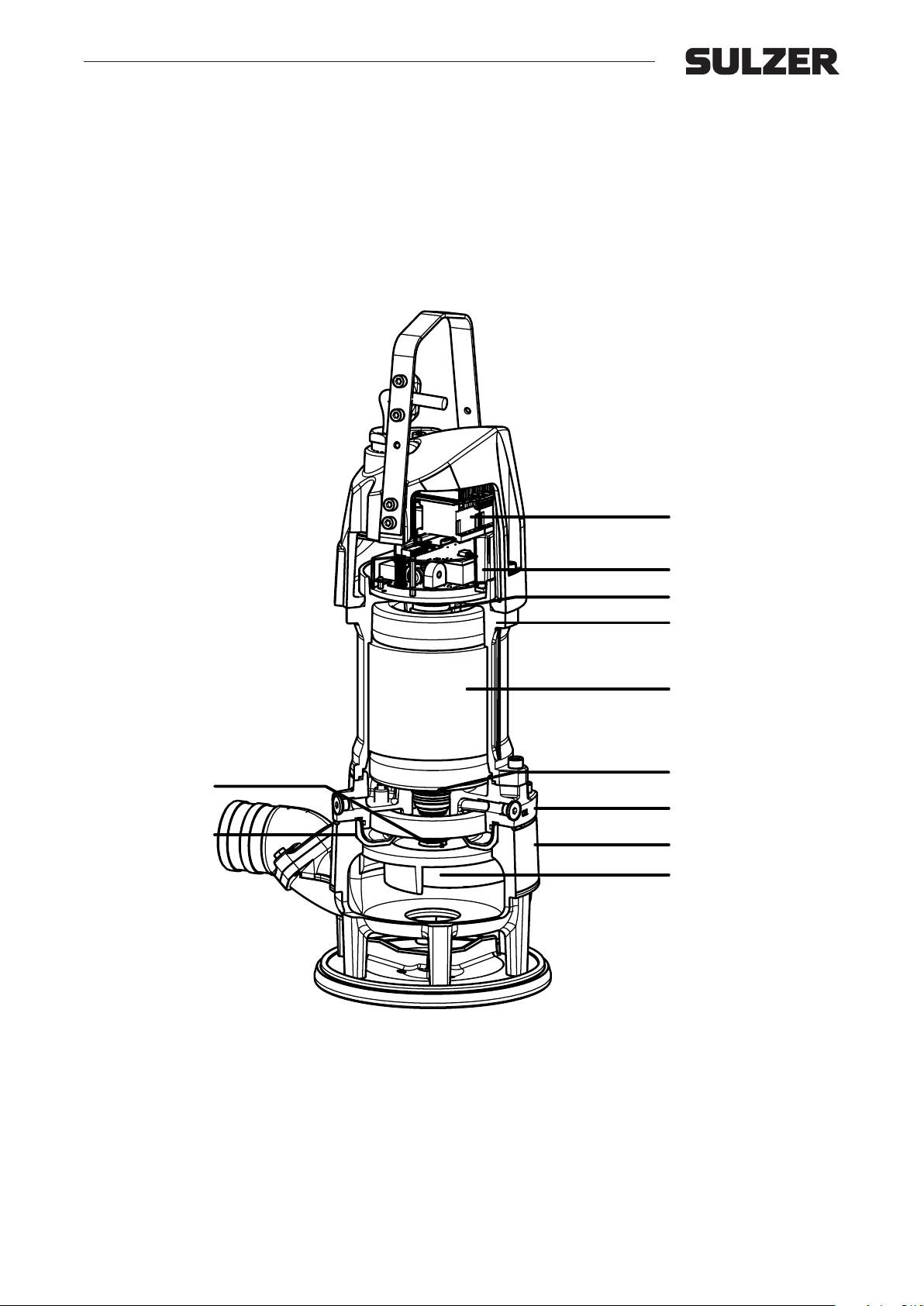
Workshop manual
XJ 25 - 110, XJC 50 - 110, XJS 25 - 110
XJS
Rotor and shaft
Diuser
Contactor
AquaTronic
Ball bearing, upper
Motor housing
Stator
Ball bearing, lower
Bearing house
Volute
Impeller
33
Page 34
Workshop manual
XJ 25 - 110, XJC 50 - 110, XJS 25 - 110
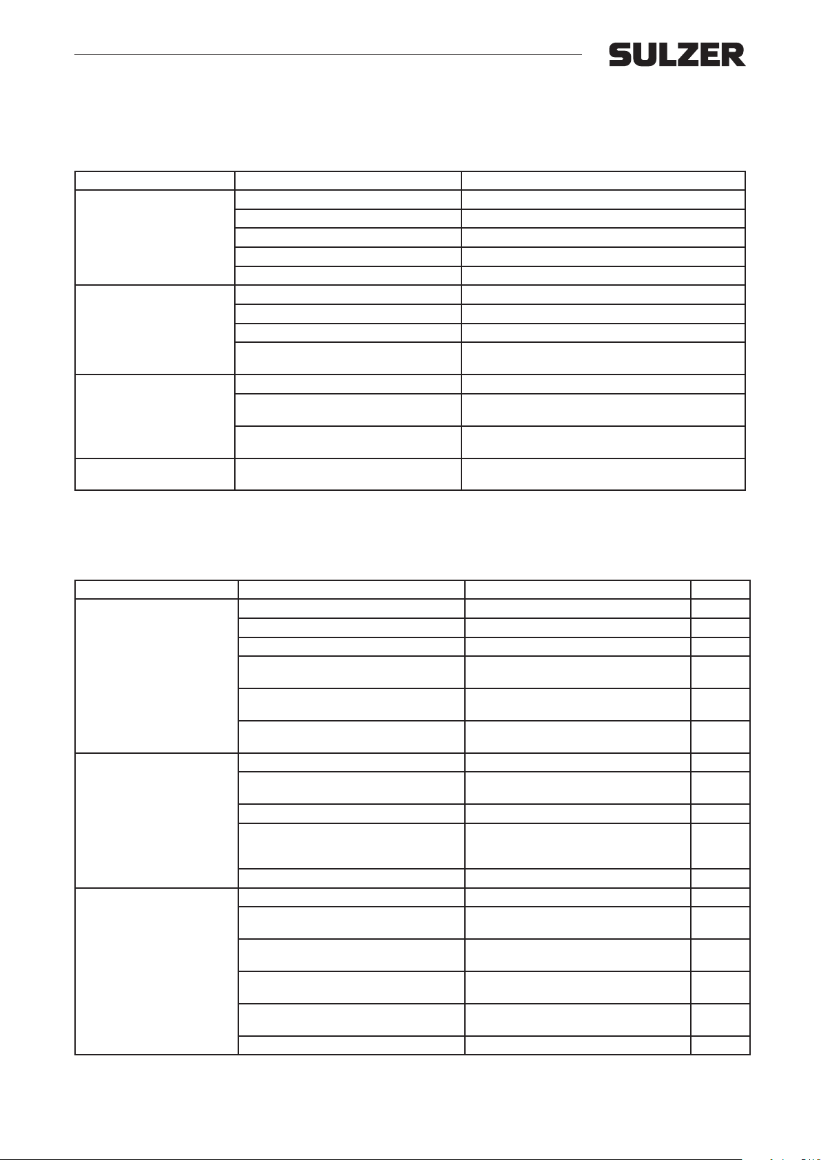
12. Troubleshooting
12.1 Troubleshooting in eld
Error Probable cause Solution
Dead incoming power lines. Check power lines.
Blown fuses or breakers. Check fuses and breakers.
The pump will not start.
The motor trips out.
Pump operating at too low
capacity.
Residual Current Device
trips out.
Phase failure. Check phases.
Blocked impeller. Check for stones, pieces of wood etc.
Loose cable. Service inspection needed.
Wrong direction of rotation. Shift phases.
Excessive water temperature (max 40 ºC). Check water temperature.
Blocked impeller. Check for stones, pieces of wood etc.
Low voltage due to long cables, or inadequate power supply (generator).
Clogged strainer. Clean strainer.
Sharp bends, folds or restrictions of the
discharge hose.
Total delivery head (static head + frictions
losses) too high.
Moisture in stator. Service inspection needed.
Check cables and power supply.
Adjust hose.
Exchange for a pump with sucient capacity for the
task.
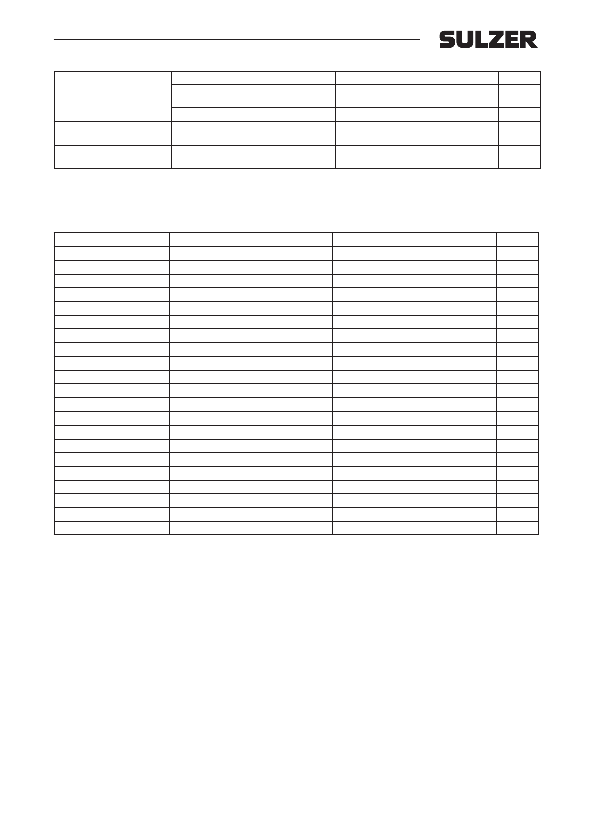
12.2 Troubleshooting/service inspection without service program
Error Probable cause Solution Chapter
Defective cable. Replace cable. 8.10
Defective contactor unit. Replace contactor. 8.2
Burned motor. Complete pump overhaul. 1-8
The pump will not start.
The motor trips out.
Water found inside top cover,
and/or motor housing.
Blocked impeller. Check for stones, pieces of wood etc.
Water intrusion. See error “Water found inside top cover,
Loose wires between motor / contactor /
power cable.
Pump overloaded due to material build up. Hydraulic check and cleaning. 4
Blocked impeller. Check for stones, pieces of wood etc.
Blocked rotor. Complete pump overhaul. 1-8
Burned motor caused by water entering
the pump through shaft seal or cable entr y
area.
Oil in motor housing. Clean from oil. Replace secondary seal. 1-8
Pump cable damaged or cut. Replace cable. 8.10
Loose cable gland or faulty assembly of
gland.
Damaged o-ring, foreign material between
motor housing and jacket, or cover.
Wire(s) pinched between top cover and
main cover.
Loose or missing screws that secure top
cover to main cover.
Water entered through inspection hole. Check motor inspection plug 3
Check diuser for damages.
and/or motor housing”.
Fasten wires and check for water intrusion.
Check cables in connection chamber.
Replace damaged impeller.
Complete pump overhaul.
Replace cable gland and cable seal. 8 .10
Complete pump overhaul.
Replace damaged parts.
Replace damaged wires and check
contactor.
Complete pump overhaul.
Replace missing parts.
4.2 + 8.8
8.10
4.3
1-8
1-8
1-8
1-8
34
Page 35
Workshop manual
XJ 25 - 110, XJC 50 - 110, XJS 25 - 110
Defective shaft seal. Change primary seal. 5
Water in the oil chamber.
Pump operating at too low
capacity.
Residual Current Device trips
out.
Faulty assembly of o-rings, mechanical
seal or upper diuser.
Worn seals. Replace parts and dry motor. 5 + 7
Worn or damaged impeller and/or wear
ring and/or diuser.
Moisture in stator. Dry motor.
Replace parts.
Hydraulic check
5
4
1-8
12.3 Troubleshooting/service inspection with Service Diagnostic Program for AquaTronic.
Error Probable cause Solution Chapter
35
Page 36
Copyright © Sulzer Ltd 2019
Sulzer Pump Solutions Ireland Ltd, Clonard Road, Wexford, Ireland
Tel +353 53 91 63 200, www.sulzer.com
 Loading...