


 Loading...
Sullair 900H, 750, 750H, 750HH, 1050 User Manual
...USER MANUAL
PORTABLE AIR COMPRESSOR
600H, 700HH, 750, 750H, 750HH, 825, 900H, 1050
CATERPILLAR IT4 C9.3
WARRANTY NOTICE
Failure to follow the instructions and procedures in this manual or, misuse of this equipment will VOID its warranty!
PART NUMBER:
02250201-740 R02
KEEP FOR
FUTURE
REFERENCE
©COPYRIGHT 2013 SULLAIR
The information in this manual is current as of its publication date, and applies to compressor serial number:
201309190000
and all subsequent serial numbers.

AIR CARE SEMINAR TRAINING
Sullair Air Care Seminars are courses that provide hands-on instruction for the proper operation, maintenance, and servicing of Sullair products. Individual seminars on portable compressors and compressor electrical systems are offered at regular intervals throughout the year at Sullair’s corporate headquarters training facility located at Michigan City, Indiana.
Instruction includes training on the function and installation of Sullair service parts, troubleshooting common faults and malfunctions, and actual equipment operation. These seminars are recommended for maintenance, contractor maintenance, and service personnel.
For detailed course outlines, schedule, and cost information contact:
SULLAIR TRAINING DEPARTMENT
1-888-SULLAIR or
219-879-5451 (ext. 5623) www.sullair.com training@sullair.com
- Or Write -
Sullair
3700 E. Michigan Blvd.
Michigan City, IN 46360
Attn: Service Training Department.
Disclosure: Portions of this manual were used with the expressed authority of Dexter Axle®, but Dexter Axle® is not responsible for the accuracy of the information contained herein.

TABLE OF CONTENTS
SECTION 1—SAFETY
5 |
1.1 |
GENERAL |
5 |
1.2 |
TOWING * |
81.3 PRESSURE RELEASE
91.4 FIRE AND EXPLOSION
101.5 MOVING PARTS
111.6 HOT SURFACES, SHARP EDGES AND SHARP CORNERS
111.7 TOXIC AND IRRITATING SUBSTANCES
121.8 ELECTRICAL SHOCK
13 |
1.9 |
LIFTING |
13 |
1.10 |
ENTRAPMENT |
131.11 JUMP STARTING
141.12 IMPLEMENTATION OF LOCKOUT/TAGOUT
151.13 CALIFORNIA PROPOSITION 65
161.14 SYMBOLS AND REFERENCES
SECTION 2—DESCRIPTION
21 |
2.1 |
INTRODUCTION |
21 |
2.2 |
DESCRIPTION OF COMPONENTS |
24 |
2.3 |
SULLAIR COMPRESSOR UNIT, FUNCTIONAL DESCRIPTION |
242.4 COMPRESSOR COOLING AND LUBRICATION SYSTEM, FUNCTIONAL DESCRIPTION
262.5 CAPACITY CONTROL SYSTEM, FUNCTIONAL DESCRIPTION
272.6 AFTERCOOLED AIR SYSTEM, FUNCTIONAL DESCRIPTION
292.7 AIR INLET SYSTEM, FUNCTIONAL DESCRIPTION
302.8 PIPING AND INSTRUMENTATION DIAGRAM—LP/HP DUAL (100-175 PSI)
322.9 PIPING AND INSTRUMENTATION DIAGRAM—LP/HP SINGLE (100, 150, 175 PSI)
342.10 PIPING AND INSTRUMENTATION DIAGRAM—HHP DUAL (100-200 PSI)
36 |
2.11 |
PIPING AND INSTRUMENTATION DIAGRAM—HHP SINGLE (200 PSI) |
38 |
2.12 |
PIPING AND INSTRUMENTATION DIAGRAM—HYDRAULIC SYSTEM |
40 |
2.13 |
PIPING AND INSTRUMENTATION DIAGRAM—ENGINE SYSTEM |
42 |
2.14 |
PIPING AND INSTRUMENTATION DIAGRAM—LP DUAL |
44 |
2.15 |
PIPING AND INSTRUMENTATION DIAGRAM—LP ENGINE SYSTEM |
462.16 INSTRUMENT PANEL GROUP, FUNCTIONAL DESCRIPTION
472.17 ENGINE CONTROL MODULE, FUNCTIONAL DESCRIPTION
51 |
2.18 HYDRAULIC FAN DRIVE SYSTEM |

TABLE OF CONTENTS
52 |
2.19 |
ELECTRICAL SYSTEM, FUNCTIONAL DESCRIPTION |
54 |
2.20 |
WIRING DIAGRAM 900C |
58 |
2.21 |
WIRING DIAGRAM, ELECTRONIC CONTROLLER |
602.22 WIRING DIAGRAM, CLEAN EMISSIONS MODEL (CEM) INTERFACE
612.23 ENGINE EXHAUST AFTERTREATMENT, FUNCTIONAL DESCRIPTION
SECTION 3—SPECIFICATIONS
63 |
3.1 |
TABLE OF SPECIFICATIONS—600H, 700HH, 750, 750H, 750HH |
65 |
3.2 |
TABLE OF SPECIFICATIONS—825, 900H, 1050 |
653.3 LUBRICATION GUIDE—COMPRESSOR
663.4 APPLICATION GUIDE
663.5 LUBRICATION GUIDE, ENGINE
673.6 IDENTIFICATION, TANDEM AXLE (DTQ)
SECTION 4—OPERATION
69 |
4.1 |
GENERAL |
69 |
4.2 |
PURPOSE OF CONTROLS |
714.3 COMPRESSOR START-UP PROCEDURE
724.4 EXHAUST REGENERATION PROCEDURE
734.5 SHUTDOWN PROCEDURE
SECTION 5—MAINTENANCE
75 |
5.1 |
GENERAL |
75 |
5.2 |
DAILY OPERATION |
755.3 ENGINE COOLANT
765.4 MAINTENANCE AFTER INITIAL 50 HOURS OF OPERATION
76 |
5.5 |
MAINTENANCE EVERY 100 HOURS |
765.6 MAINTENANCE EVERY 250 HOURS
775.7 MAINTENANCE EVERY 300 HOURS
77 |
5.8 |
MAINTENANCE EVERY 600 HOURS |
77 |
5.9 |
MAINTENANCE EVERY 1000 HOURS |
77 |
5.10 |
MAINTENANCE EVERY 1500 HOURS |
77 |
5.11 |
MAINTENANCE EVERY YEAR OR 1500 HOURS |
77 |
5.12 |
MAINTENANCE EVERY YEAR |
77 |
5.13 |
MAINTENANCE AFTER 4500 HOURS OF OPERATION |
775.14 MAINTENANCE AFTER 5000 HOURS OF OPERATION
785.15 PARTS REPLACEMENT & ADJUSTMENT PROCEDURES
82 |
5.16 |
HYDRAULIC SYSTEM MAINTENANCE |
87 |
5.17 |
TROUBLESHOOTING GUIDE |
SECTION 6—NOISE CONTROL
91 |
6.1 |
NOISE EMISSIONS WARRANTY |
916.2 TAMPERING WITH THE NOISE CONTROL SYSTEM IS PROHIBITED
926.3 NOISE EMISSIONS MAINTENANCE AND MAINTENANCE RECORD LOG
Section 1
SAFETY
NOTE
OPERATOR IS REQUIRED TO READ
ENTIRE INSTRUCTION MANUAL.
1.1GENERAL
Sullair designs and manufactures all of its products so they can be operated safely. However, the responsibility for safe operation rests with those who use and maintain these products. The following safety precautions are offered as a guide which, if conscientiously followed, will minimize the possibility of accidents throughout the useful life of this equipment. Read the CIMA Safety Manual prior to compressor operation and towing, if applicable in your area.
The air compressor should be operated only by those who have been trained and delegated to do so, and who have read and understood this Operator’s Manual. Failure to follow the instructions, procedures and safety precautions in this manual can result in accidents and injuries.
NEVER start the air compressor unless it is safe to do so. DO NOT attempt to operate the air compressor with a known unsafe condition. Tag the air compressor and render it inoperative by disconnecting and locking out all power at source or otherwise disabling its prime mover so others who may not know of the unsafe condition cannot attempt to operate it until the condition is corrected.
Use and operate the air compressor only in full compliance with all pertinent OSHA requirements and/or all pertinent Federal, State and Local codes or requirements.
DO NOT modify the compressor except with written factory approval.
Each day, walk around the air compressor and inspect for leaks, loose or missing parts, damaged parts or parts out of adjustment. Perform all recommended daily maintenance.
Inspect for torn, frayed, blistered or otherwise deteriorated and degraded hoses. Replace as required.
1.2TOWING *
PREPARING TO TOW
 WARNING
Do NOT tow the compressor should its weight exceed the rated limit of the tow vehicle, as the vehicle may not brake safely with excess weight. See rated limit in tow vehicle Operator's Manual, and review its instructions and other requirements for safe towing.
A.Prior to hitching the air compressor to the tow vehicle, inspect all attachment parts and equipment, checking for (I) signs of excessive wear or corrosion, (II) parts that are cracked, bent, dented or otherwise deformed or degraded, and
(III)loose nuts, bolts or other fasteners. Should any such condition be present, DO NOT TOW until the problem is corrected.
B.Back the tow vehicle to the compressor and position it in preparation for coupling the compressor.
C.If the compressor is provided with a drawbar latched in the vertical upright position, carefully unlatch drawbar and lower it to engage the coupling device. If not, raise drawbar with the jack to engage coupling device or otherwise couple the compressor to the towing vehicle.
* While not towed in the usual sense of the word, many of these instructions are directly applicable to skid-mounted portable air compressors as well.
5

 WARNING
This equipment may be tongue heavy. DO NOT attempt to raise or lower the drawbar by hand if the weight is more than you can safely handle.
Use the screw jack provided or a chain fall if you cannot lift or lower it without avoiding injury to yourself or others. Keep hands and fingers clear of the coupling device and all other pinch points. Keep feet clear of drawbar to avoid injury in case it should slip from your hands.
A.Make sure the coupling device is fully engaged, closed and locked.
B.If chains are provided, pass each chain through its point of attachment on the towing vehicle; then hook each chain to itself by passing the grab hook over (not through) a link. Cross chains under the front of drawbar before passing them through points of attachment on towing vehicle to support the front of drawbar in case it should accidentally become uncoupled.
C.Make sure that the coupling device and adjacent structures on the towing vehicle (and also, if utilized, chain adjustment, brake and/or electrical interconnections) DO NOT interfere with or restrict motion of any part of the compressor, including its coupling device, with respect to the towing vehicle when maneuvering over any anticipated terrain.
D.If provided, make sure chain length, brake and electrical interconnections provide sufficient slack to prevent strain when cornering and maneuvering, yet are supported so they cannot drag or rub on road, terrain or towing vehicle surfaces which might cause wear that could render them inoperative.
 WARNING
This equipment may be tongue heavy. DO NOT attempt to raise or lower the drawbar by hand if the weight is more than you can safely handle.
6
SECTION 1
 CAUTION
Retract the front screw jack only after attaching the compressor to the tow vehicle. Raise the screw jack to its full up position and pull the pin connecting the jack to the drawbar. Rotate the screw jack to its stowed position, parallel to the drawbar, and reinsert the pin. Make sure the jack is secured in place prior to towing.
If a caster wheel is provided on the screw jack it is part of the screw jack and can not be removed. Follow the same procedure for stowing away the wheeled jack as you would for the standard screw jack. Pull the pin connecting the jack to the drawbar and raise the screw jack to its full up position. Rotate the screw jack to its stowed position, parallel to the drawbar, and reinsert the pin. Make sure the jack is secured in place prior to towing.
E.On two-wheeled models, fully retract front screw jack and any rear stabilizer legs. If a caster wheel is provided on the screw jack it is part of the screw jack, and can not be removed. Follow the same procedure for stowing away the wheeled jack as you would for the standard screw jack. Pull the pin connecting the jack to the drawbar and raise the screw jack to its full upright position. Rotate the screw jack to its stowed position, parallel to the drawbar, and reinsert the pin. Make sure the jack is secured in place prior to towing.
F.Make sure tires are in good condition and are the size (load range) specified and are inflated to the specified pressures. DO NOT change the tire size or type. Also, make sure wheel bolts, lugs or nuts are tightened to the specified torques.
G.If provided, make sure all dual stop, tail directional and clearance lights are operating properly and that their lenses are clean and functional. Also, make sure all reflectors and reflecting surfaces, including the slow moving vehicle emblem on compressors provided with same, are clean and functional.
H.Make sure all service air hoses (not air brake hoses) are disconnected or are fully stowed and secured on hose reels, if provided.

SECTION 1
I.Make sure all access doors and tool box covers E. Avoid potholes, rocks and other obstructions,
are closed and latched. If the compressor is large enough to hold a man, make sure all personnel are out before closing and latching access doors.
J.Make sure parking brakes in towing vehicle are set, or that its wheels are chocked or blocked, or that it is otherwise restrained from moving. Then, release the compressor parking brakes, if provided.
K.Make sure the compressor wheels are not chocked or blocked, and that all tie-downs, if any, are free.
L.Test running brake operation, including breakaway switch operation if provided, before attempting to tow the compressor at its rated speed or less when conditions prevail.
M.DO NOT carry loose or inappropriate tools, equipment or supplies on or in the compressor.
N.DO NOT load this equipment with accessories or tools such that it is unbalanced from side to side or front to back. Such unbalance will reduce the towability of this equipment and may increase the possibility of tipping, rolling over, jackknifing, etc. Loss of control of the towing vehicle may result.
TOWING
A.Observe all Federal, State, and Local laws while towing this equipment (including those specifying minimum speed).
B.DO NOT exceed the towing speeds listed below under ideal conditions. Reduce your speed according to posted speed limits, weather, traffic, road or terrain conditions:
1.Two axle four-wheel or three axle six-wheel steerable models: 15 MPH (24 km/h).
2.All other models: 55 MPH (88 km/h).
C.Remember that the portable air compressor may approach or exceed the weight of the towing vehicle. Maintain increased stopping distances accordingly. DO NOT make sudden lane changes, U-turns or other maneuvers. Such maneuvers can cause the compressor to tip, roll over, jackknife or slide and cause loss of control of the towing vehicle. Tipping, rolling over, etc. can occur suddenly without warning. U-turns especially should be made slowly and carefully.
D.Avoid grades in excess of 15° (27%).
and soft shoulders or unstable terrain.
F.Maneuver in a manner that will not exceed the freedom of motion of the compressor’s drawbar and/ or coupling device, in or on the towing vehicle’s coupling device and/or adjacent structure whether towing forward or backing up, regardless of the terrain being traversed.
G.DO NOT permit personnel to ride in or on the compressor.
H.Make sure the area behind, in front of, and under the compressor is clear of all personnel and obstructions prior to towing in any direction.
I.DO NOT permit personnel to stand or ride on the drawbar, or to stand or walk between the compressor and the towing vehicle.
PARKING OR LOCATING COMPRESSOR
A.Park or locate compressor on a level surface, if possible. If not, park or locate compressor across grade so the compressor does not tend to roll downhill. DO NOT park or locate compressor on grades exceeding 15° (27%).
B.Make sure compressor is parked or located on a firm surface that can support its weight.
C.Park or locate compressor so the wind, if any, tends to carry the exhaust fumes and radiator heat away from the compressor air inlet openings, and also where the compressor will not be exposed to excessive dust from the work site.
D.On steerable models, park compressor with front wheels in straight-ahead position.
E.Set parking brakes and disconnect breakaway switch cable and all other interconnecting electrical and/or brake connections, if provided.
F.Block or chock both sides of all wheels.
G.If provided, unhook chains and remove them from the points of chain attachment on the towing vehicle, then hook chains to bail on drawbar or wrap chains around the drawbar and hook them to themselves to keep chains off the ground which might accelerate rusting.
H.Lower front screw jack and/or any front and rear stabilizer legs. Make sure the surface they contact has sufficient load bearing capability to support the weight of the compressor.
7

 WARNING
This equipment may be tongue heavy. DO NOT attempt to raise or lower the drawbar by hand if the weight is more than you can safely handle.
 CAUTION
Retract the front screw jack only after attaching the compressor to the tow vehicle. Raise the screw jack to its full up position and pull the pin connecting the jack to the drawbar. Rotate the screw jack to its stowed position, parallel to the drawbar, and reinsert the pin. Make sure the jack is secured in place prior to towing.
On two-wheeled models, fully retract front screw jack and any rear stabilizer legs. If a caster wheel is provided on the screw jack it is part of the screw jack and can not be removed. Follow the same procedure for stowing away the wheeled jack as you would for the standard screw jack. Pull the pin connecting the jack to the drawbar and raise the screw jack to its full up position. Rotate the screw jack to its stowed position, parallel to the drawbar, and reinsert the pin. Make sure the jack is secured in place prior to towing.
I.If a caster wheel is provided on the screw jack, it is part of the screw jack and cannot be removed. Follow the same procedure for stowing away the wheeled jack as you would for the standard screw jack. Raise the screw jack to its full upright position and pull the pin connecting the jack to the drawbar. Rotate the screw jack to its stowed position, parallel to the drawbar and reinsert the pin. Make sure the jack is secured in place prior to towing.
J.Disconnect coupling device, keeping hands and fingers clear of all pinch points. If the compressor is provided with a drawbar, DO NOT attempt to lift the drawbar or if hinged, to raise it to the upright position by hand, if the weight is more than you can safely handle. Use a screwjack or
8
SECTION 1
chain fall if you cannot lift or raise the drawbar without avoiding injury to yourself or others.
K.Move the towing vehicle well clear of the parked compressor and erect hazard indicators, barricades and/or flares (if at night) if compressor is parked on or adjacent to public roads. Park so as not to interfere with traffic.
NOTE
While not towed in the usual sense of the word, many of these instructions are directly applicable to skidmounted portable air compressors as well.
1.3PRESSURE RELEASE
A.Open the pressure relief valve at least weekly to make sure it is not blocked, closed, obstructed or otherwise disabled.
B.Install an appropriate flow-limiting valve between the compressor service air outlet and the shutoff (throttle) valve, when an air hose exceeding 1/2" (13 mm) inside diameter is to be connected to the shutoff (throttle) valve, to reduce pressure in case of hose failure, per OSHA Standard 29 CFR 1926.302 (b) (7) or any applicable Federal, State and Local codes, standards and regulations.
C.When the hose is to be used to supply a manifold, install an additional appropriate flow-limiting valve between the manifold and each air hose exceeding 1/2" (13 mm) inside diameter that is to be connected to the manifold to reduce pressure in case of hose failure.
D.Provide an appropriate flow-limiting valve for each additional 75 feet (23 m) of hose in runs of air hose exceeding 1/2" (13 mm) inside diameter to reduce pressure in case of hose failure.
E.Flow-limiting valves are listed by pipe size and rated CFM. Select appropriate valve accordingly.
F.DO NOT use tools that are rated below the maximum rating of this compressor. Select tools, air hoses, pipes, valves, filters and other fittings accordingly. DO NOT exceed manufacturer’s rated safe operating pressures for these items.
G.Secure all hose connections by wire, chain or other suitable retaining device to prevent tools or hose ends from being accidentally disconnected and expelled.

SECTION 1
H.Open fluid filler cap only when compressor is not running and is not pressurized. Shut down the compressor and bleed the sump (receiver) to zero internal pressure before removing the cap.
I.Vent all internal pressure prior to opening any line, fitting, hose, valve, drain plug, connection or other component, such as filters and line oilers, and before attempting to refill optional air line anti-icer systems with antifreeze compound.
J.Keep personnel out of line with and away from the discharge opening of hoses, tools or other points of compressed air discharge.
K.DO NOT use air at pressures higher than 30 psig (2.1 bar) for cleaning purposes, and then only with effective chip guarding and personal protective equipment per OSHA Standard 29 CFR 1910.242 (b) or any applicable Federal, State and Local codes, standards and regulations.
L.DO NOT engage in horseplay with air hoses as death or serious injury may result.
M.This equipment is supplied with an ASME designed pressure vessel protected by an ASME rated relief valve. Lift the handle once a week to make sure the valve is functional. DO NOT lift the handle while machine is under pressure.
N.If the machine is installed in an enclosed area it is necessary to vent the relief valve to the outside of the structure or to an area of non-exposure.
O.DO NOT remove radiator filler cap until the coolant temperature is below its boiling point. Then loosen cap slowly to its stop to relieve any excess pressure and make sure coolant is not boiling before removing cap completely. Remove radiator filler cap only when cool enough to touch with a bare hand.
P.The ethyl ether in the replaceable cylinders used in diesel ether starting aid systems (optional) is under pressure. DO NOT puncture or incinerate those cylinders. DO NOT attempt to remove the center valve core or side pressure relief valve from these cylinders regardless of whether they are full or empty.
Q.If a manual blowdown valve is provided on the receiver, open the valve to ensure all internal pressure has been vented prior to servicing any pressurized component of the compressor air/ fluid system.
1.4FIRE AND EXPLOSION
 WARNING
Do not attempt to operate the compressor in any classification of hazardous environment or potentially explosive atmosphere unless the compressor has been specially designed and manufactured for that duty.
A.Refuel at a service station or from a fuel tank designed for its intended purpose. If this is not possible, ground the compressor to the dispenser prior to refueling.
B.Clean up spills of lubricant or other combustible substances immediately, if such spills occur.
C.Shut off air compressor and allow it to cool. Then keep sparks, flames and other sources of ignition away and DO NOT permit smoking in the vicinity when adding fuel, checking or adding electrolyte to batteries, checking or adding fluid, checking diesel engine ether starting aid systems, replacing cylinders, or when refilling air line anti-icer systems antifreeze compound.
D.DO NOT permit fluids, including air line anti-icer system antifreeze compound or fluid film, to accumulate on, under or around acoustical material, or on any external surfaces of the air compressor. Wipe down using an aqueous industrial cleaner or steam clean as required. If necessary, remove acoustical material, clean all surfaces and then replace acoustical material. Any acoustical material with a protective covering that has been torn or punctured should be replaced immediately to prevent accumulation of liquids or fluid film within the material. DO NOT use flammable solvents for cleaning purposes.
E.Disconnect and lock out all power at source prior to attempting any repairs or cleaning of the compressor or of the inside of the enclosure, if any.
F.Keep electrical wiring, including all terminals and pressure connectors in good condition. Replace any wiring that has cracked, cut, abraded or otherwise degraded insulation, or terminals that are worn, discolored or corroded. Keep all terminals and pressure connectors clean and tight.
G.Turn off battery charger before making or breaking connections to the battery.
9

H.Keep grounded and/or conductive objects such as tools away from exposed live electrical parts such as terminals to avoid arcing which might serve as a source of ignition.
I.Replace damaged fuel tanks or lines immediately rather than attempt to weld or otherwise repair them. DO NOT store or attempt to operate the compressor with any known leaks in the fuel system. Tag the compressor and render it inoperative until repair can be made.
J.Remove any acoustical material or other material that may be damaged by heat or that may support combustion and is in close proximity, prior to attempting weld repairs.
K.Keep suitable fully charged Class BC or ABC fire extinguisher or extinguishers nearby when servicing and operating the compressor.
L.Keep oily rags, trash, leaves, litter or other combustibles out of and away from the compressor.
M.Open all access doors and allow the enclosure to ventilate thoroughly prior to attempting to start the engine.
N.DO NOT operate compressor under low overhanging leaves or permit such leaves to contact hot exhaust system surfaces when operating the compressor in forested areas.
O.Ethyl ether used in diesel engine ether starting aid systems is extremely flammable. Change cylinders, or maintain or troubleshoot these systems only in well-ventilated areas away from heat, open flame or sparks. DO NOT install, store or otherwise expose ether cylinders to temperatures above 160 °F (71 °C). Remove ether cylinder from the compressor when operating in ambient temperatures above 60 °F (16 °C).
P.DO NOT attempt to use ether as a starting aid in gasoline engines or diesel engines with glow plugs as serious personnel injury or property damage may result.
Q.DO NOT spray ether into compressor air filter or into an air filter that serves both the engine and the compressor as serious damage to the compressor or personal injury may result.
R.Antifreeze compound used in air line anti-icer systems contains methanol which is flammable. Use systems and refill with compound only in well-ventilated areas away from heat, open flames or sparks. DO NOT expose any part of these systems or the antifreeze compound to
10
SECTION 1
temperatures above 150 °F (66 °C). Vapors from the antifreeze compound are heavier than air. DO NOT store compound or discharge treated air in confined or unventilated areas. DO NOT store containers of antifreeze compound in direct sunlight.
S.Store flammable fluids and materials away from your work area. Know where fire extinguishers are and how to use them, and for what type of fire they are intended. Check readiness of fire suppression systems and detectors if so equipped.
T.DO NOT operate the compressor without proper flow of cooling air or water or with inadequate flow of lubricant or with degraded lubricant.
U.DO NOT attempt to operate the compressor in any classification of hazardous environment unless the compressor has been specially designed and manufactured for that duty.
1.5MOVING PARTS
 WARNING
Disconnect and lock out all power at source and verify at the compressor that all circuits are de-energized to minimize the possibility of accidental start-up, or operation, prior to attempting repairs or adjustments. This is especially important when compressors are remotely controlled.
A.Keep hands, arms and other parts of the body and also clothing away from couplings, fans and other moving parts.
B.DO NOT attempt to operate the compressor with the fan, coupling or other guards removed.
C.Wear snug-fitting clothing and confine long hair when working around this compressor, especially when exposed to hot or moving parts.
D.Make sure all personnel are out of and/or clear of the compressor prior to attempting to start or operate it.
E.When adjusting the controls, it may require operation of the equipment during adjustment. DO NOT come in contact with any moving parts while adjusting the control regulator and setting the engine RPM. Make all other adjustments with
SECTION 1
the engine shut off. When necessary, make adjustment, other than setting control regulator and engine RPM, with the engine shut off. If necessary, start the engine and check adjustment. If adjustment is incorrect, shut engine off, readjust, then restart the engine to recheck adjustment.
F.Keep hands, feet, floors, controls and walking surfaces clean and free of fluid, water or other liquids to minimize the possibility of slips and falls.
1.6HOT SURFACES, SHARP EDGES AND SHARP CORNERS
A.Avoid bodily contact with hot fluid, hot coolant, hot surfaces and sharp edges and corners.
B.Keep all parts of the body away from all points of air discharge and away from hot exhaust gases.
C.Wear personal protective equipment including gloves and head covering when working in, on or around the compressor.
D.Keep a first aid kit handy. Seek medical assistance promptly in case of injury. DO NOT ignore small cuts and burns as they may lead to infection.
1.6.1TIER 4 EMISSIONS MODULE - IF EQUIPPED
General Guidelines: Thermal Protection. The main exhaust piping routes exhaust gas from the engine to the Clean Emissions Module (CEM). Normal operating temperatures can reach up to 530 °C (986 °F). During regeneration of the Diesel Particulate Filter (DPF), the Auxiliary Regeneration Device (ARD) will be in operation, this creating temperatures above normal engine exhaust temperatures. Gas temperatures during the regeneration period can reach 750 °C (1382 °F).
 T4 - WARNING
Increased DPF skin temperature and exhaust gas temperature may occur in the event of an unexpected engine/aftertreatment failure. An unexpected failure of the engine/aftertreatment may increase temperature at the DPF as high as 900 °C (1652 °F) gas temperature and 750 °C (1382 °F) skin temperature. This may result in fire, burn, or explosion hazards, which may result in personal injury or death. Do not expose flammable material or explosive atmospheres to exhaust gas or exhaust system components during regeneration. The aftertreatment skin temperature and the gas temperature are difficult to measure and/or simulate and are dependent upon many factors including the following: the nature of the engine/ aftertreatment failure, the design and packaging of the aftertreatment, the engine speed/load conditions, the condition of the aftertreatment and ambient conditions. Therefore, the potential temperatures are provided as a guideline even under conditions of unexpected engine and/or aftertreatment failure. Proper precautions should be taken to ensure that the aftertreatment device is not mounted in close proximity to components that may be damaged by heat.
1.7TOXIC AND IRRITATING SUBSTANCES
A.DO NOT use air from this compressor for respiration (breathing) except in full compliance with OSHA Standards 29 CFR 1920 and any other Federal, State or Local codes or regulations.
 DANGER
11

 DANGER
INHALATION HAZARD!
Death or serious injury can result from inhaling compressed air without using proper safety equipment. See OSHA standards and/or any applicable Federal, State, and Local codes, standards and regulations on safety equipment.
B.DO NOT use air line anti-icer systems in air lines supplying respirators or other breathing air utilization equipment and DO NOT discharge air from these systems into unventilated or other confined areas.
C.Operate the compressor only in open or adequately ventilated areas.
D.Locate the compressor so that exhaust fumes are not apt to be carried towards personnel, air intakes servicing personnel areas or towards the air intake of any portable or stationary compressor.
E.Fuels, fluids and lubricants used in this compressor are typical of the industry. Care should be taken to avoid accidental ingestion and/or skin contact. In the event of ingestion, seek medical treatment promptly. Wash with soap and water in the event of skin contact. Consult Material Safety Data Sheet for information pertaining to the specific fluid.
F.Wear goggles or a full face shield when adding antifreeze compound to air line anti-icer systems.
G.Wear an acid-resistant apron and a face shield or goggles when servicing the battery. If electrolyte is spilled on skin or clothing, immediately flush with large quantities of water.
H.Ethyl ether used in diesel engine ether starting aid systems is toxic, harmful or fatal if swallowed. Avoid contact with the skin or eyes and avoid breathing the fumes. If swallowed, DO NOT induce vomiting and call a physician immediately.
I.Wear goggles or a full face shield when testing ether starting aid systems or when adding antifreeze compound to air line anti-icer systems. Keep openings of valve or atomizer tube of ether starting aid system pointed away from yourself and other personnel.
J.If air line anti-icer system antifreeze compound enters the eyes or if fumes irritate the eyes, they should be washed with large quantities of clean
12
SECTION 1
water for fifteen minutes. A physician, preferably an eye specialist, should be contacted immediately.
K.DO NOT store ether cylinders or air line anti-icer system antifreeze compound in operator’s cabs or in other similar confined areas.
L.The antifreeze compound used in air line antifreeze systems contains methanol and is toxic, harmful or fatal if swallowed. Avoid contact with the skin or eyes and avoid breathing the fumes. If swallowed, induce vomiting by administering a tablespoon of salt, in each glass of clean, warm water until vomit is clear, then administer two teaspoons of baking soda in a glass of clean water. Have patient lay down and cover eyes to exclude light. Call a physician immediately.
M.When handling DEF (Diesel Emissions Fluid) wear protective clothing. Tools and clothing that come in contact with DEF must be cleaned.
 -IMPORTANT
It is very important that all electrical connectors are protected from coming in contact with DEF. If not, there is a risk that DEF will cause oxidation in the wiring that is not possible to clean. The resulting oxidation will result in a wiring/connection failure. Water and compressed air fail to remove DEF. If a connector has been in contact with DEF, it must be changed immediately to prevent the chemical from further migrating into the wiring cable harness, which happens at a speed of 0.6 m/h.
 -WARNING
In case of DEF contact with eyes or skin, the affected area must be thoroughly rinsed with lukewarm water. If you breathe any fumes, make sure and breathe fresh air.
1.8ELECTRICAL SHOCK
A.Keep the towing vehicle or equipment carrier, compressor hoses, tools and all personnel at least 10 feet (3 m) from power lines and buried cables.
B.Stay clear of the compressor during electrical storms! It can attract lightning.

SECTION 1
C.Keep all parts of the body and any hand-held tools or other conductive objects away from exposed live parts of electrical system. Maintain dry footing, stand on insulating surfaces and DO NOT contact any other portion of the compressor when making adjustments or repairs to exposed live parts of the electrical system.
D.Attempt repairs in clean, dry and well lighted and ventilated areas only.
1.9LIFTING
A.If the compressor is provided with a lifting bail, then lift by the bail provided. If no bail is provided, then lift by sling. Compressors to be air lifted by helicopter must not be supported by the lifting bail, but by slings instead. In any event, lift only in full compliance with OSHA Standards 29 CFR 1910 subpart N or any other Local, State, Military and Federal regulations that may apply.
B.Inspect lifting bail and points of attachment for cracked welds and for cracked, bent, corroded or otherwise degraded members and for loose bolts or nuts prior to lifting.
C.Make sure entire lifting, rigging and supporting structure has been inspected, is in good condition and has a rated capacity of at least the net weight of the compressor plus an additional 10% allowance for weight of water, snow, ice, mud, stored tools, and equipment. If your are unsure of the weight, then weigh compressor before lifting.
D.Make sure lifting hook has a functional safety latch or equivalent, and is fully engaged and latched on the bail.
E.Use guide ropes or equivalent to prevent twisting or swinging of the compressor once it has been lifted clear of the ground.
F.DO NOT attempt to lift in high winds.
G.Keep all personnel out from under and away from the compressor whenever it is suspended.
H.Lift compressor no higher than necessary.
I.Keep lift operator in constant attendance whenever compressor is suspended.
J.Set compressor down only on a level surface capable of supporting at least its net weight plus an additional 10% allowance for the weight of water, snow, ice, mud, stored tools, and/or equipment.
K.If the compressor is provided with parking brakes, make sure they are set, and in any event, block or chock both sides of all running wheels before disengaging the lifting hook.
1.10 ENTRAPMENT
A.Make sure all personnel are out of compressor before closing and engaging enclosure doors.
B.If the compressor is large enough to hold a man and if it is necessary to enter it to perform service adjustments, inform other personnel before doing so, or else secure the access door in the open position to avoid the possibility of others closing and possibly latching the door with personnel inside.
1.11 JUMP STARTING
A.Observe all safety precautions mentioned elsewhere in this manual.
B.Batteries may contain hydrogen gas which is flammable and explosive. Keep flames, sparks and other sources of ignition away.
C.Batteries contain acid which is corrosive and poisonous. DO NOT allow battery acid to contact eyes, skin, fabrics or painted surfaces as serious personal injury or property damage could result. Flush any contacted areas thoroughly with water immediately. Always wear an acid-resistant apron and face shield when attempting to jump start the compressor.
D.Remove all vent caps (if so equipped) from the battery or batteries in the compressor. DO NOT permit dirt or foreign matter to enter the open cells.
E.Check fluid level. If low, bring fluid to proper level before attempting to jump start (not applicable to maintenance-free batteries).
F.DO NOT attempt to jump start if fluid is frozen or slushy. Bring batteries up to at least 60 °F (16 °C) before attempting to jump start or it may explode.
G.Cover open cells of all compressor batteries with clean dampened cloths before attempting to jump start.
H.Attempt to jump start only with a vehicle having a negative ground electrical system with the same voltage, and is also equipped with a battery or batteries of comparable size or larger than sup-
13

plied in the compressor. DO NOT attempt to jump start using motor generator sets, welders or other sources of DC power as serious damage may result.
I.Bring the starting vehicle alongside the compressor, but DO NOT permit metal to metal contact between the compressor and the starting vehicle.
J.Set the parking brakes of both the compressor (if provided) and the starting vehicle or otherwise block both sides of all wheels.
K.Place the starting vehicle in neutral or park, turn off all non-essential accessory electrical loads and start its engine.
L.Use only jumper cables that are clean, in good condition and are heavy enough to handle the starting current.
M.Avoid accidental contact between jumper cable terminal clips or clamps and any metallic portion of either the compressor or the starting vehicle to minimize the possibility of uncontrolled arcing which might serve as a source of ignition.
N.Positive battery terminals are usually identified by a plus (+) sign on the terminal and the letters POS adjacent to the terminal. Negative battery terminals are usually identified by the letters NEG adjacent to the terminal or a negative (-) sign.
O.Connect one end of a jumper cable to the positive (POS) (+) battery terminal in the starting vehicle. When jump starting 24V compressors and if the starting vehicle is provided with two (2) 12V batteries connected in series, connect the jumper cable to the positive (POS) (+) terminal of the ungrounded battery.
P.Connect the other end of the same jumper cable to the positive (POS) (+) terminal of the starter motor battery in the compressor when jump starting 24V compressors, to the positive (POS) (+) terminal of the ungrounded battery in the compressor.
Q.Connect one end of the other jumper cable to the grounded negative (NEG) (-) terminal of the battery in the starting vehicle. When jump starting 24V compressors and if the starting vehicle is provided with two (2) 12V batteries connected in series, connect the jumper cable to the negative (NEG) (-) terminal of the grounded battery.
R.Check your connections. DO NOT attempt to start a 24V compressor with one 12V battery in
14
SECTION 1
the starting vehicle. DO NOT apply 24V to one 12V battery in the compressor.
S.Connect the other end of this same jumper cable to a clean portion of the compressor engine block away from fuel lines, the crank case breather opening and the battery.
T.Start the compressor in accordance with normal procedure. Avoid prolonged cranking.
U.Allow the compressor to warm up. When the compressor is warm and operating smoothly at normal idle RPM, disconnect the jumper cable from the engine block in the compressor, then disconnect the other end of this same cable from the grounded negative (NEG) (-) terminal of the battery in the starting vehicle. Then disconnect the other jumper cable from the positive (POS)
(+)terminal of the battery in the compressor, or if provided with two (2) 12V batteries connected in series, from the ungrounded battery in the compressor, and finally, disconnect the other end of this same jumper cable from the positive (POS)
(+)terminal of the battery in the starting vehicle or from the positive (POS) (+) terminal of the ungrounded battery in the starting vehicle, if it is provided with two (2) 12V batteries connected in series.
V.Remove and carefully dispose of the dampened cloths, as they may now be contaminated with acid, then replace all vent caps.
1.12IMPLEMENTATION OF LOCKOUT/TAGOUT
The energy control procedure defines actions necessary to lockout a power source of any machine to be repaired, serviced or set-up, where unexpected motion, or an electrical or other energy source, would cause personal injury or equipment damage. The power source on any machine shall be locked out by each employee doing the work except when motion is necessary during setup, adjustment or troubleshooting.
A.The established procedures for the application of energy control shall cover the following elements and actions and shall be initiated only by Authorized Persons and done in the following sequence:
1.Review the equipment or machine to be locked and tagged out.
2.Alert operator and supervisor of which machine is to be worked on, and that power and utilities will be turned off.
SECTION 1
3.Check to make certain no one is operating the machine before turning off the power.
4.Turn off the equipment using normal shutdown procedure.
5.Disconnect the energy sources:
a.Air and hydraulic lines should be bled, drained and cleaned out. There should be no pressure in these lines or in the reservoir tanks. Lockout or tag lines or valves.
b.Any mechanism under tension or pressure, such as springs, should be released and locked out or tagged.
c.Block any load or machine part prior to working under it.
d.Electrical circuits should be checked with calibrated electrical testing equipment and stored energy and electrical capacitors should be safely discharged.
6.Lockout and/or Tagout each energy source using the proper energy isolating devices and tags. Place lockout hasp and padlock or tag at the point of power disconnect where lockout is required by each person performing work. Each person shall be provided with their own padlock and have possession of the only key. If more than one person is working on a machine each person shall affix personal lock and tag using a multi-lock device.
7.Tagout devices shall be used only when power sources are not capable of being locked out by use of padlocks and lockout hasp devices. The name of the person affixing tag to power source must be on tag along with date tag was placed on power source.
8.Release stored energy and bring the equipment to a “zero mechanical state”.
9.Verify Isolation: Before work is started, test equipment to ensure power is disconnected.
B.General Security
1.The lock shall be removed by the “Authorized” person who put the lock on the energy-isolating device. No one other than the person/persons placing padlocks and lockout hasps on power shall remove padlock and lockout hasps and restore power. However, when the authorized person who applied the lock is unavailable to remove it his/her Supervisor may remove
padlock/padlocks and lockout hasps and restore power only if it is first:
a.verified that no person will be exposed to danger.
b.verified that the “Authorized” person who applied the device is not in the facility.
c.noted that all reasonable efforts to contact the “Authorized” person have been made to inform him or her that the lockout or tagout device has been removed.
d.ensured that the “Authorized” person is notified of lock removal before returning to work.
2.Tagout System—Tags are warning devices affixed at points of power disconnect and are not to be removed by anyone other that the person placing tag on power lockout. Tags shall never be by-passed, ignored, or otherwise defeated
1.13CALIFORNIA PROPOSITION 65
 WARNING
CALIFORNIA PROPOSITION 65 WARNING
Diesel engine exhaust and some of its constituents are known to the State of California to cause cancer, birth defects and other reproductive harm.
Battery posts, terminals and related accessories contain lead and other compounds known to the State of California to cause cancer and birth defects and other reproductive harm. Wash hands after handling.
15

SECTION 1
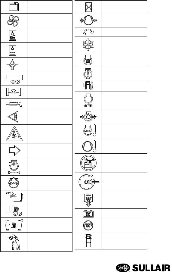
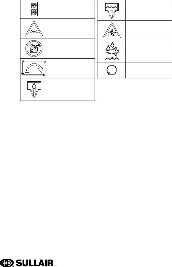
1.14 SYMBOLS AND REFERENCES
The symbols below may or may not be used. Please refer to the decals set forth on the machine for applicable symbols.
DIESEL FUEL |
HEARING PROTECTION |
|
|
||
ROTARY COMPRESSOR |
|
|
|
HARD HAT |
|
TEST RUN |
|
|
DRAIN |
SAFETY GLASSES |
|
HIGH PRESSURE |
|
|
SHUT-OFF VALVE |
HEARING PROTECTION |
|
|
||
W/ SAFETY |
DO NOT REMOVE |
|
NO |
||
MANUAL |
||
|
||
ENGINE |
DO NOT BREATHE |
|
|
||
|
COMPRESSED AIR |
|
COMPRESSOR |
DO NOT STAND ON |
|
|
||
ENGINE OIL |
SERV. VALVE |
|
DO NOT OPERATE |
||
|
||
ENGINE COOLANT |
W/ DOORS OPEN |
|
WATER |
DO NOT OPEN |
|
|
||
OIL |
DO NOT STACK |
|
|
||
DO NOT |
ELECTRICAL SHOCK |
|
CLOSED MECHANICAL |
AIR FLOW |
|
|
||
FUSE |
|
|
|
HOT SURFACE |
|
LOW PRESSURE |
|
|
|
PRESSURIZED VESSEL |
|
READ MANUAL |
PRESSURIZED |
|
|
||
|
COMPONENT |
|
BRAKES |
SAFETY SYMBOLS 1 |
16

SECTION 1
DANGEROUS OUTLET |
ENGINE START |
REMOTELY |
ENGINE ECM |
|
|
CONTROLLED |
|
|
READ/WRITE DATA |
CORROSIVE |
INTAKE AIR |
|
|
WARNING |
EXHAUST GAS |
|
|
DO NOT |
FAN GUARD |
|
|
MAINTENANCE |
|
BELOW TEMPERATURE |
BELT GUARD |
|
|
DO NOT TOW |
SERVICE POINT |
BAR/PSI |
|
BATTERY |
LOW TEMPERATURE |
|
|
BATTERY DISCONNECT |
STD AIR |
|
|
OFF |
A/C AIR |
ON |
24 HOURS |
|
|
RESET |
|
|
BELTS |
NO FORKLIFT |
FILTER |
FORK LIFT HERE |
STRAINER |
|
|
|
SAFETY SYMBOLS 2 |
DIRECTION OF ROTATION |
|
17
SECTION 1
RADIATOR
AIR-CIRCULATING FAN
AIR-COOLED
OIL COOLER
LIQUID-COOLED OIL COOLER
LUBRICATION
TRAILER TOWING MODE
AXEL
LUBRICANT GREASE
EXAMINE, CHECK
CRUSH/PINCH POINT
FUNCTIONAL ARROW
ENGINE INTAKE
AIR FILTER
PRESSURE CONTROL
INLET VALVE SPRING
INTERNAL FUEL
EXTERNAL FUEL
SIDE DOOR T-LATCH
HOUR METER
COMPRESSOR AIR
PRESSURE
START
CONTROL
ENGINE PREHEAT
LOW TEMP AID
ENGINE WARNING
FUEL LEVEL
ENGINE RPM
ENGINE OIL
PRESSURE
ENGINE COOLANT
TEMPERATURE
COMPRESSOR
TEMPERATURE
DO NOT MIX
COOLANTS
AFTERCOOLER
BYPASS VALVE
DRAIN HEATER
BATTERY HEATER
COMPRESSOR
OIL HEAT
STACKING LIMIT
BY NUMBER
SAFETY SYMBOLS 3
18
SECTION 1
DO NOT OPERATE |
WATER DRAIN |
|
WHILE STACKED |
||
|
||
PRESSURIZED SPRING |
SEVER (FAN) |
|
|
DO NOT MIX FLUIDS
DEF FLUID ONLY
AUTO START/STOP |
RUN |
|
|
|
SAFETY SYMBOLS 4 |
FLUID DRAIN |
|
19

SECTION 1
20
600H, 700HH, 750, 750H, 750HH, 825, 900H, 1050 USER MANUAL
Section 2
DESCRIPTION
2.1INTRODUCTION
Sullair Portable Air Compressor models offer superior performance and reliability while requiring only minimal maintenance.
The compressor is equipped with a Sullair rotary screw compressor unit. Compared to other compressors, the Sullair is unique in mechanical reliability and compressor durability. No inspection is required of the working parts within the compressor unit.
As you continue reading this manual and come to learn how the compressor operates and is cared for, you will see how surprisingly easy it is to keep a Sullair compressor in top operating condition.
Read Section 5: MAINTENANCE to keep your compressor in top operating condition. Should any problem or question arise which cannot be answered in this text, contact your nearest Sullair representative or the Sullair Service Department.
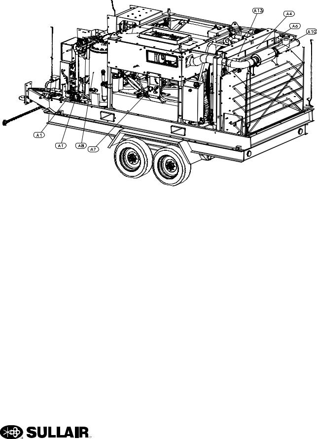
2.2DESCRIPTION OF COMPONENTS
Refer to Figure 2-1 and Figure 2-2. The components and assemblies of the Sullair Portable Air Compressor models are clearly shown. The package includes a compressor, diesel engine, exhaust system including an iT4 compliant emissions module, compressor/engine inlet system, compressor cooling and lubrication system, compressor discharge system, capacity control system, instrument panel and electrical system. The machine is also supplied with sound deadening insulation to lower noise
emissions to meet EPA or CE, most federal, state, or local noise requirements. The Sullair compressor unit is driven by an industrial engine designed to provide enough horsepower at rated conditions. Refer to
Engine Operator’s Manual for a more detailed description of the engine.
The engine cooling system is comprised of a radiator, high capacity fan and thermostats. The high capacity variable speed hydraulic fan blows air through the radiator, keeping the engine at the proper operating temperature while optimizing the fuel consumption by effectively adjusting the fan speed to efficiently accommodate engine conditions.
The same fan also cools the fluid in the compressor cooling and lubrication system. While passing through the radiator, the fan air also passes through the compressor fluid cooler, which is mounted adjacent to the radiator. As air passes through the cooler, some of the heat of compression is removed from the fluid.
The same fan also cools the return fuel supply as well as the fan drive hydraulic fluid. The coolers for these circuits are integrated and mounted in front of the compressor cooler and radiator. The cooling fan is hydraulically driven. As air passes through the aftercooler heat is removed which was introduced by the engine’s turbo charger. The engine is coupled to the compressor unit with a non-lubricated, vulcanized rubber disk and a drive flange-type coupling. All compressor models are supplied with a fuel tank large enough to keep the compressor running through a full 8-hour shift.
21

600H, 700HH, 750, 750H, 750HH, 825, 900H, 1050 USER MANUAL |
SECTION 2 |
A1 MOISTURE SEPARATOR |
A8 RECEIVER TANK |
A2 REGULATOR VALVES |
A9 E-STOP |
A3 ENGINE COOLANT FILL |
A10 ENGINE MUFFLER/SPARK ARRESTOR |
A4 ENGINE FLUID COOLER |
A11 MANUAL ENCLOSURE |
A5 AFTERCOOLER |
A12 BATTERY DISCONNECT SWITCH |
A6 ENGINE CHARGE AIR COOLER |
A13 COMPRESSOR OIL COOLER |
A7 FUEL FILL |
|
|
Figure 2-1: Compressor |
Note: Canopy, engine, and compressor are removed for clarity.
22
SECTION 2 |
600H, 700HH, 750, 750H, 750HH, 825, 900H, 1050 USER MANUAL |
A1 MOISTURE SEPARATOR |
A8 RECEIVER TANK |
A2 REGULATOR VALVES |
A9 E-STOP |
A3 ENGINE COOLANT FILL |
A10 ENGINE MUFFLER/SPARK ARRESTOR |
A4 ENGINE FLUID COOLER |
A11 MANUAL ENCLOSURE |
A5 AFTERCOOLER |
A12 BATTERY DISCONNECT SWITCH |
A6 ENGINE CHARGE AIR COOLER |
A13 COMPRESSOR OIL COOLER |
A7 FUEL FILL |
|
|
Figure 2-2: Compressor |
Note: Canopy, engine, and compressor are removed for clarity.
23

600H, 700HH, 750, 750H, 750HH, 825, 900H, 1050 USER MANUAL |
SECTION 2 |
2.3SULLAIR COMPRESSOR UNIT, FUNCTIONAL DESCRIPTION
Sullair compressors feature the Sullair compressor unit, a single-stage, positive displacement, flood lubricated-type compressor. This unit provides
continuous compression to meet your needs.
NOTE
With a Sullair compressor, there is no maintenance or inspection of the internal parts of the compressor unit permitted in accordance with the terms of the warranty.
Sullair compressors are factory-filled with Sullair AWF lubricant. For more information on fluid fill, refer to “Lubrication Guide—Compressor” on page 65.
Fluid is injected into the compressor unit hoses and mixes directly with the air as the rotors turn, compressing the air. The fluid flow has three basic functions:
1.As coolant, it controls the rise of air temperature normally associated with the heat of compression.
2.Seals the clearance paths between the rotors and the stator and also between the rotors themselves.
3.Acts as a lubricating film between the rotors allowing one rotor to directly drive the other, which is an idler.
After the air/fluid mixture is discharged from the compressor unit, the fluid is separated from the air. At this time, the air flows through an aftercooler and moisture separator, if equipped, then to your service line.
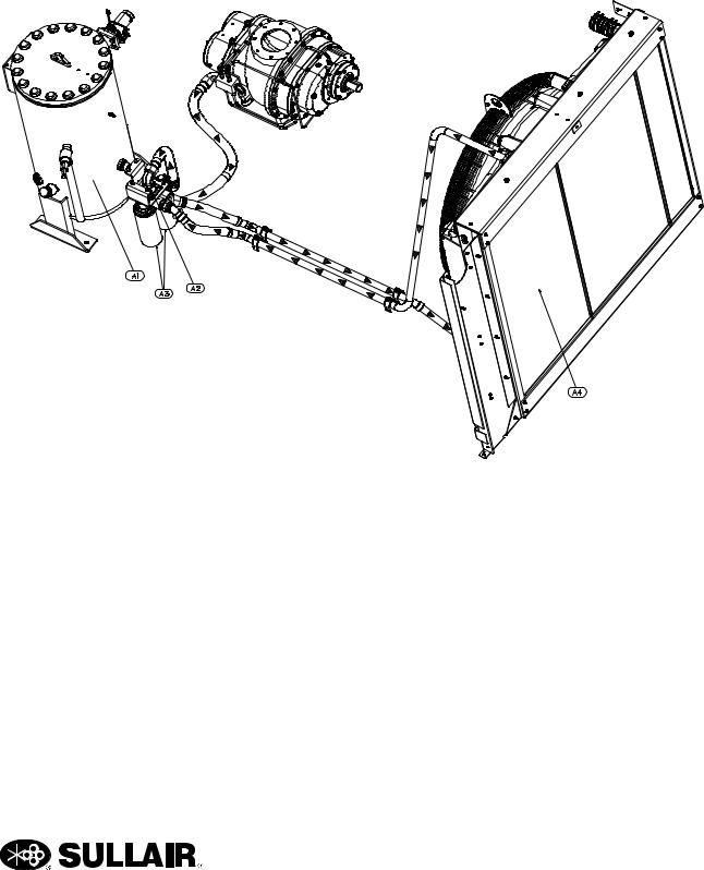
2.4COMPRESSOR COOLING AND LUBRICATION SYSTEM, FUNCTIONAL DESCRIPTION
Refer to Figure 2-2. The compressor cooling and lubrication system is designed to provide adequate lubrication as well as maintain the proper operating temperature of the compressor. In addition to the cooler and fan, the system consists of a main filter and thermal valve. The fan is hydraulically driven, refer to Section 2.18 for more detail.
Fluid is used in the system as a coolant and a lubricant. The fluid is housed in the receiver tank.
Upon start up, the fluid temperature is cool, and routing to the cooler is not required. The fluid first enters the thermal valve and then flows on to the compressor unit, bypassing the cooler. As the compressor continues to operate, the temperature of the fluid rises and the thermal valve element begins to shift. This forces a portion of the fluid to the fluid cooler. The cooler is a radiator-type that works in conjunction with the hydraulic fan. The fan forces air through the cooler removing the heat of compression from the fluid. From the cooler, the fluid is routed back to the thermal valve.
Before the temperature of the fluid reaches the valve set point, cooled fluid is mixed with warmer fluid. When the temperature of the fluid reaches 170°F (77°C), the thermal element shifts completely causing all fluid to flow to the cooler. The thermal valve incorporates a pressure relief valve, which allows fluid to bypass the cooler, if the cooler becomes plugged or frozen. This helps assure that fluid will continue to be provided to the compressor for lubrication. After the fluid passes through the thermal valve it is then directed through the main fluid filter. There, the fluid is filtered in preparation for injection into the compression chamber and bearings of the compressor unit. The filter has a replaceable element and a built-in bypass valve which allows the fluid to flow even when the filter element becomes plugged and requires changing or when the viscosity of the fluid is too high for adequate flow. After the fluid is properly filtered, it then flows on to the compressor unit where it lubricates, seals and cools the compression chamber as well as lubricates the bearings and gears.
24
SECTION 2 |
600H, 700HH, 750, 750H, 750HH, 825, 900H, 1050 USER MANUAL |
A1 |
RECEIVER TANK |
A3 |
FLUID FILTER |
A2 |
THERMAL VALVE |
A4 |
COMPRESSOR OIL COOLER |
Figure 2-2: Compressor Oil, Cooling and Lubrication - All Models
25

600H, 700HH, 750, 750H, 750HH, 825, 900H, 1050 USER MANUAL |
SECTION 2 |
2.5CAPACITY CONTROL SYSTEM, FUNCTIONAL DESCRIPTION
Refer to Figure 2-3, Figure 2-4 and Figure 2-5. The purpose of the control system is to regulate the amount of air intake in accordance with the amount of compressed air demanded. The control system consists of an inlet valve, the high and low pressure regulators, the pressure reducing regulator, the blowdown/ running blowdown valve, the controller, a <ON> switch, and the <PRESSURE> selector switch.
START—0 TO 65 PSIG (0 TO 4.5 BAR)
Keep the <ON> switch to the “ON” position to initialize the controller. Once the controller says “READY” on LCD, press <ON> switch to the “START” position. In the “START” position, the inlet valve is held closed by the springs in the inlet valve. The valve is cracked open by a vacuum in the compressor and is allowed to build up to 65 psig (4.5 bar). The reason for keeping the valve closed during start is to allow the engine to warm up without being loaded by the compressor. Air pressure is contained in the receiver tank by the minimum pressure valve which has a set point of 65 psig (4.5 bar). At this point the valve opens allowing the air to pass to the service valve. After the engine has warmed up the machine automatically transitions to “RUN” mode.
LOW PRESSURE/SINGLE PRESSURE—
80 TO 100 PSIG (5.5 TO 6.9 BAR)
With the <PRESSURE> switch in the "LOW" position, and the controller in "RUN" mode, the service valve can now be opened. Pressure from the 60 psig (4.1 bar) reducing regulator opens up the inlet valve and the controller increases the engine speed to full load (1800 rpm). As the demand for air decreases, the controller commands the engine to reduce speed to idle (1400 rpm) and the inlet valve closes, where it stabilizes until the air demand is required again. If left in the idle state (>1400 rpm) for periods exceeding 10 minutes the engine rpm will drop down further to a low idle state (1000rpm) until a demand for air is seen, in order to reduce fuel consumption when not needed. If the machine is not marked with an "H" or "HH", it is a single pressure machine and will not have a <PRESSURE> switch. The machine will run as if it is in the "low" mode.
HIGH PRESSURE—80 TO 150 PSIG (5.5 TO 10.3 BAR) FOR “H” MODELS OR 80 TO 200
PSIG (5.5 TO 13.8 BAR) FOR “HH” MODELS
With the <PRESSURE> switch in the “HIGH” position, the low pressure regulator is blocked off by the high/low solenoid valve allowing the high pressure regulator to take over control of the machine. The 60 psig (4.1 bar) reducing regulator fully opens the inlet valve and the controller commands maximum speed (1800 rpm) from the engine. As the pressure reaches the set point of the system the high pressure regulator cracks open and closes the inlet valve and the controller returns the engine back to idle, until a demand for air is seen.
SHUTDOWN
The blowdown valve is normally closed. When the compressor is shutdown, system pressure backs up to the inlet valve causing the check spring in the inlet valve to close the air inlet valve. This sends a pressure signal to the blowdown valve causing it to open and vent the pressure in the system. After the pressure is vented, the blowdown valve spring returns the blowdown valve to the closed position.Compressor Discharge System, Functional Description
Refer to Figure 2-3. The Sullair compressor unit discharges a compressed air/fluid mixture into the receiver tank.
The receiver tank has three functions:
1.It acts as a primary fluid separator.
2.Serves as the compressor fluid storage sump.
3.Houses the final fluid separator.
The compressed air/fluid mixture enters the receiver tank and is directed against the tank side wall. By change of direction and reduction of velocity, large droplets of fluid separate and fall to the bottom of the receiver tank. The fractional percentage of fluid remaining in the compressed air collects on the surface of the final separator element as the compressed air flows through the separator. As more and more fluid collects on the element’s surface, the fluid descends to the bottom of the separator. A return line (or scavenge tube) leads from the bottom of the separator element to the inlet region of the compressor unit. Fluid collecting on the bottom of the separator element is returned to the compressor by the pressure difference between the area surrounding the separator element and the compressor inlet. An orifice (protected by a strainer) is included in this return line to help assure proper flow.
The receiver tank is code rated. A minimum pressure/ check valve, located downstream from the
26

SECTION 2 |
600H, 700HH, 750, 750H, 750HH, 825, 900H, 1050 USER MANUAL |
pressure during all conditions. This pressure is necessary for proper air/fluid separation and proper fluid circulation.
A minimum pressure/check valve at the outlet of the receiver is installed to prevent compressed air in the service line from bleeding back into the receiver on shutdown when the compressor is being run in parallel with other compressors tied to a large air system.
Fluid is added to the receiver tank via a capped fluid filler. A fluid level gauge glass enables the operator
to visually monitor the receiver tank fluid level.
 WARNING
DO NOT remove caps, plugs and/or other components when compressor is running or pressurized.
Stop compressor and relieve all internal pressure before doing so.
2.6AFTERCOOLED AIR SYSTEM, FUNCTIONAL DESCRIPTION
The purpose of the aftercooled air system is to operate the air compressor in conditions when compressed air temperatures are required to be 10 to 25 F̊(5 to 13 C)̊ over ambient temperature. The aftercooled feature of the compressor is controlled by a system of two ball valves which are standard on all large tier IV aftercooled compressor models. By shifting both ball valves to the aftercooled position the air flow from the receiver tank is forced through the aftercooler producing aftercooled air. Moving the ball valves to the standard position blocks air flow
through the cooler producing standard air. The ambient air, which is forced through the aftercooler by the hydraulic fan, cools the compressed air as it passes through the aftercooler core. Cooled air enters the moisture separator where condensation is removed from the cooler air and discharged. This condensation does carry some oil and it should be disposed of properly in accordance with local regulations. A condensation drain port is located in the frame on the curbside of the machine for convenience of condensate removal. This drain port should never be plugged or closed off in any way. From the moisture separator the compressed air goes through the discharge filters (if equipped) and on to the service valve.
NOTE
When operating at temperatures below freezing, the hydraulic fan will attempt to compensate for colder temperatures by slowing down or stopping. This will aid in allowing the aftercooler to be used in temperatures below freezing. When the Aftercooler Discharge Temperature (ADT) approaches freezing, the controller will warn of an imminent freeze alert. Aftercooled air should not be used in conditions where ADT is approaching freezing temperatures as this may cause damage to the aftercooled air discharge system. To operate in the non-aftercooled mode, position both aftercooler bypass valves to close off the aftercooled air circuit.
27

600H, 700HH, 750, 750H, 750HH, 825, 900H, 1050 USER MANUAL |
SECTION 2 |
1. |
RECEIVER TANK |
5. |
STANDARD AIR |
2. |
MINIMUM PRESSURE CHECK VALVE |
6. |
AFTERCOOLED AIR |
3. |
AIR VALVE |
7. |
A1 TO AFTERCOOLER |
4. |
MOISTURE SEPARATOR |
8. |
A2 FROM AFTERCOOLER |
Figure 2-3: Aftercooled Air System
28
SECTION 2 |
600H, 700HH, 750, 750H, 750HH, 825, 900H, 1050 USER MANUAL |
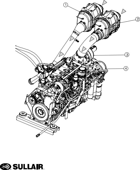
2.7AIR INLET SYSTEM, FUNCTIONAL DESCRIPTION
Refer to Figure 2-4. The compressor inlet system consists of two air filters, a compressor air inlet valve and interconnecting piping to the engine and compressor. Also, air filter restriction indicator gauges are located next to the air filter housings.
The air filter is a 2-stage unit with a safety element and dry element-type filter. This filter is capable of cleaning extremely dirty air. However, in such cases, frequent checks of the air filter will be required.
Referring to the controller, the engine air filter restriction sensor or the compressor air filter restriction sensor will indicate when restriction of the air passing through the filter becomes too high.
At this time, change the air filter element. These indicators should be checked daily, after start-up under normal conditions.
The compressor air inlet valve controls the amount of air intake of the compressor in response to the air demand.
1. |
ENGINE AIR FILTER |
3. |
AIR INLET VALVE |
2. |
COMPRESSOR AIR FILTER |
4. |
COMPRESSOR |
Figure 2-4: Air Inlet System
29
Loading...