

Page 1

WINE STORAGE
INSTALLATION GUIDE
GUÍA DE INSTALACIÓN
GUIDE D’INSTALLATION
GUIDA ALL’INSTALLAZIONE
INSTALLATIONSANLEITUNG
Page 2
WINE STORAGE
Contents
2 Wine Storage
3 Model ICBUW-24 / ICBUW-24FS Site Preparation
4 Model ICBUW-24 / ICBUW-24FS Installation
7 Model ICBBW-30 Site Preparation
10 Model ICBBW-30 Installation
Features and specifications are subject to change at any
time without notice.
Important Note
To ensure this product is installed and operated as safely
and efficiently as possible, take note of the following types
of highlighted information throughout this guide:
IMPORTANT NOTE highlights information that is especially
important.
CAUTION indicates a situation where minor injury or product
damage may occur if instructions are not followed.
WARNING states a hazard that may cause serious injury or
death if precautions are not followed.
IMPORTANT NOTE: Save these instructions for the local
electrical inspector.
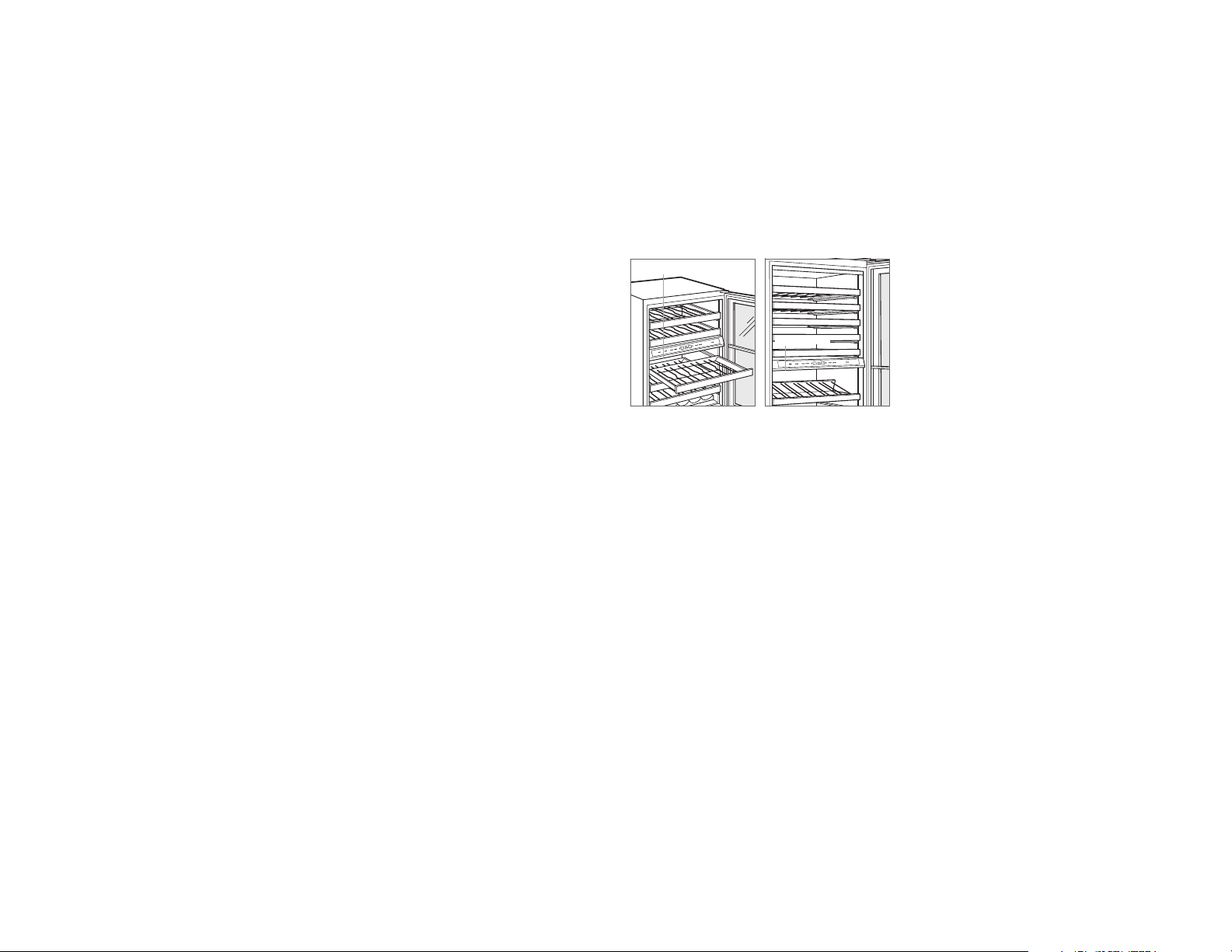
Product Information
Important product information including the model and
serial number are listed on the product rating plate. The
rating plate is located on the underside of the control panel,
on the left. Refer to the illustrations below.
If service is necessary, contact Sub-Zero factory certified
service with the model and serial number.
RATING PLATE
RATING PLATE
Models ICBUW-24 and
ICBUW-24FS.
Model ICBBW-30.
Tools and Materials
• Screwdrivers—standard, Phillips and Torx.
• Power drill.
• Drill bits (masonry bits required for concrete installation).
• Standard socket and wrench set.
• .6 m and 1.2 m levels.
• Material to protect home, flooring and cabinetry during
installation.
2 | English
Page 3
MODEL ICBUW-24 / ICBUW-24FS SITE PREPARATION
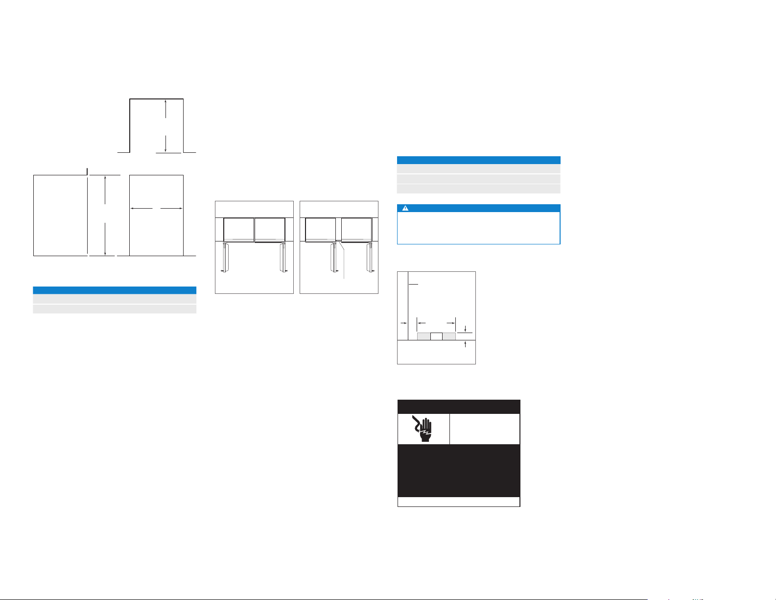
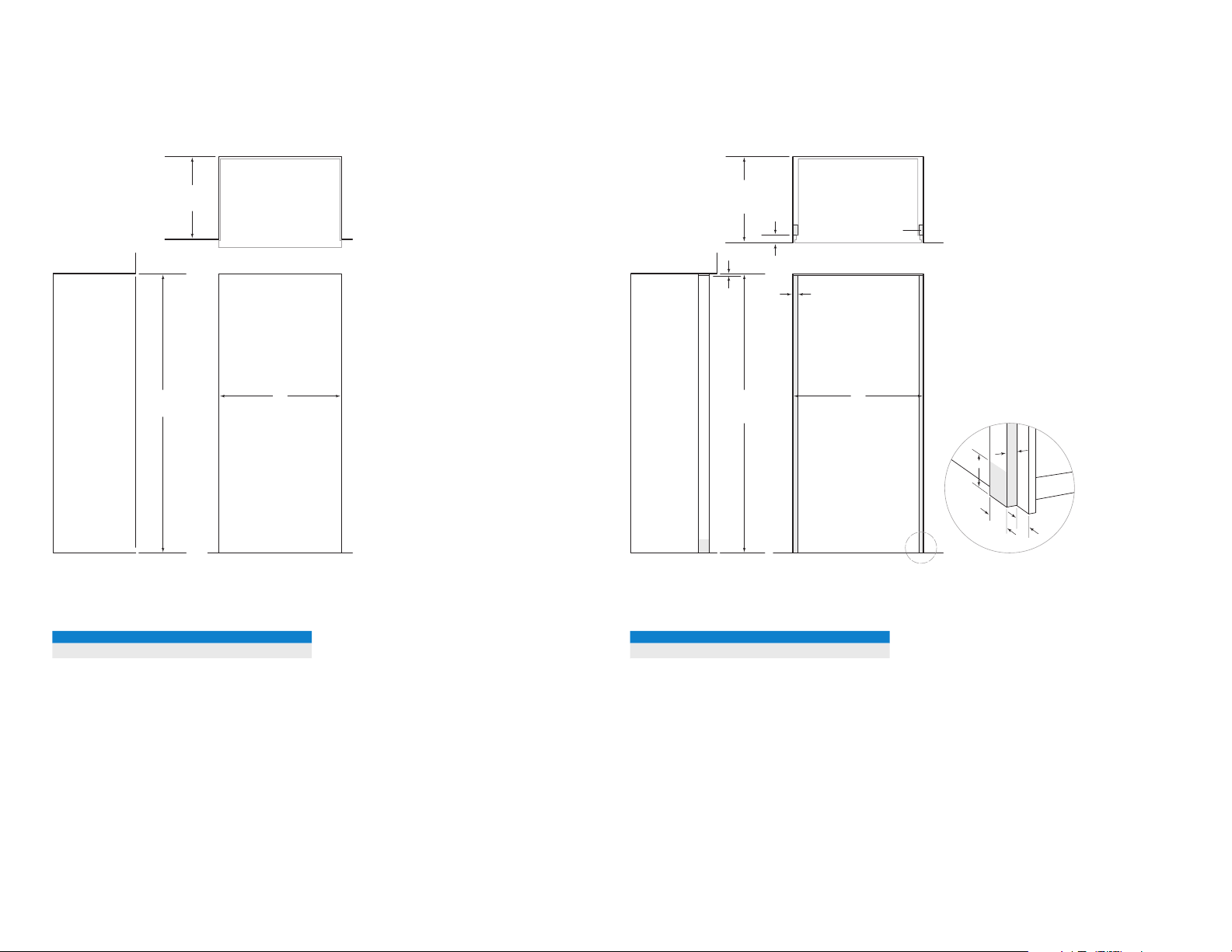
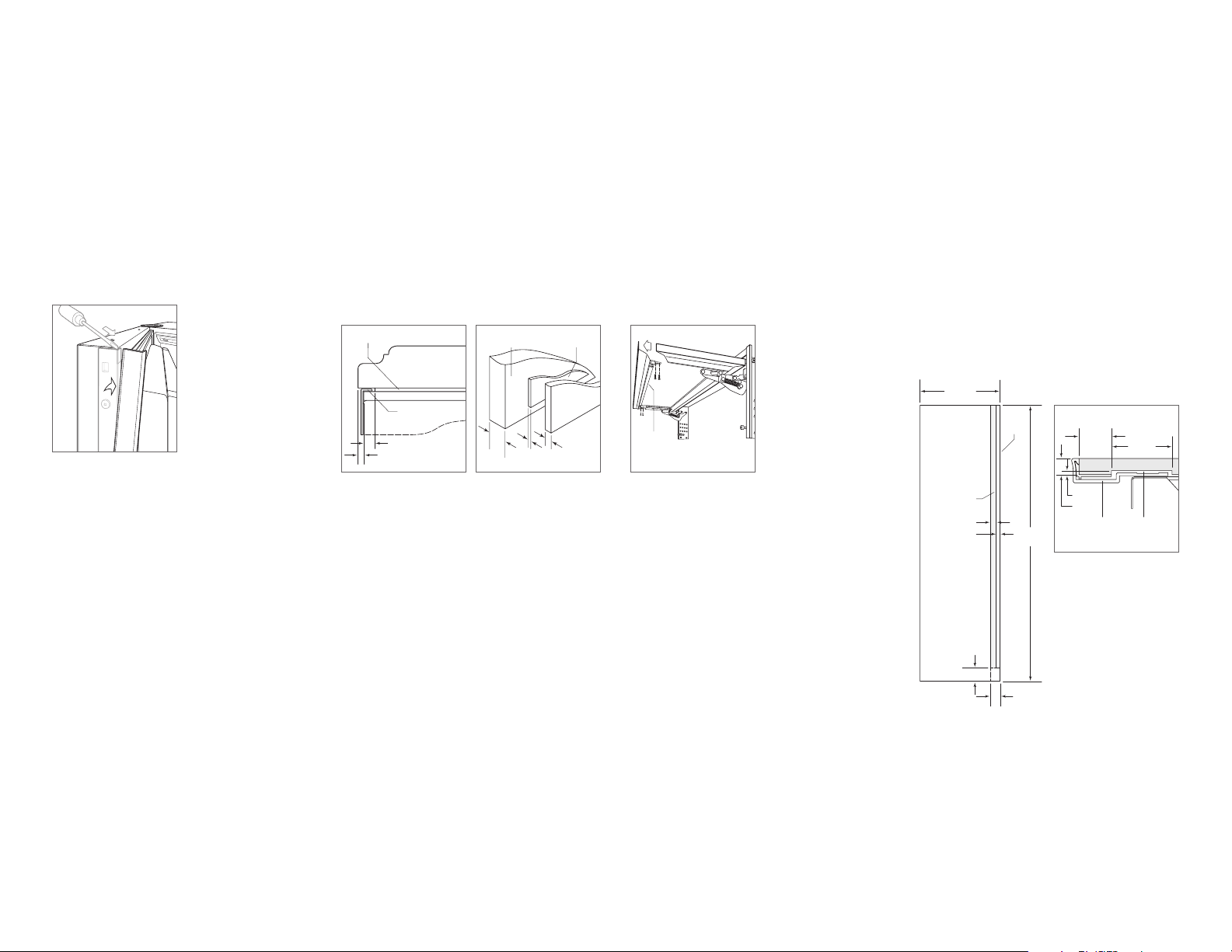
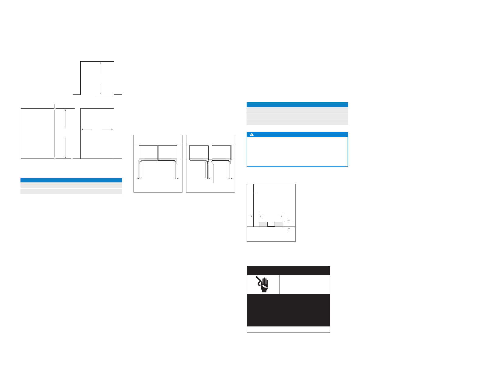
Opening Dimensions
MODEL ICBUW-24
610 mm
OPENING
DEPTH
TOP VIEW
876 mm
OPENING
HEIGHT
SIDE VIEW FRONT VIEW
OPENING WIDTH W
ICBUW-24 610 mm
Two 610 mm Models* 1222 mm
*A dual installation kit will be required for this installation.
W
OPENING WIDTH
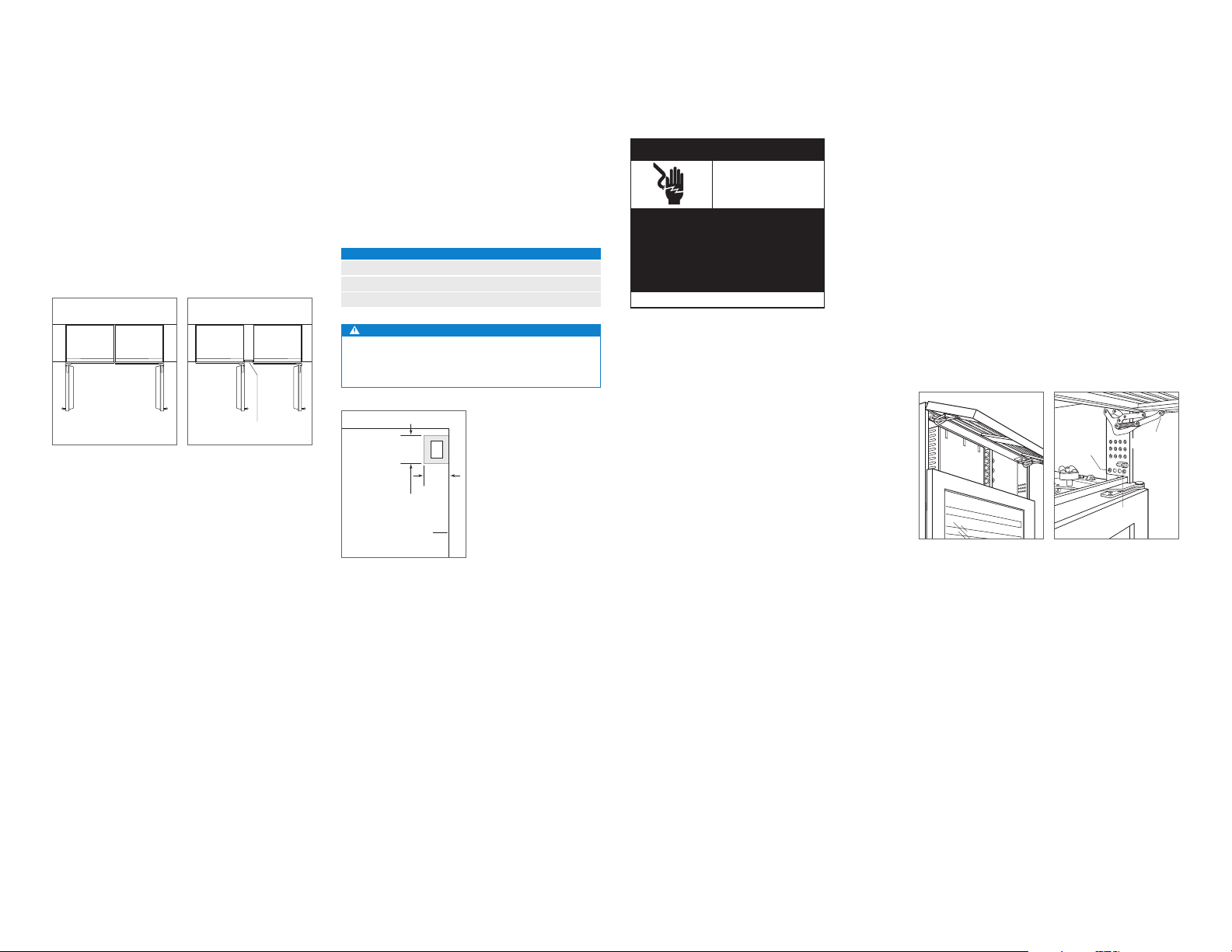
DUAL INSTALLATION
If two units are installed side by side, a dual installation kit
may be required. Installations without a custom filler strip
require a dual installation kit. If a dual installation kit is not
specified, a 51 mm filler strip is recommended between
units. Dual installations without a filler strip can only be
accomplished using two units with opposite hinges. Refer to
the illustrations below.
Dual installation kits are available through an authorized
Sub-Zero dealer.
WITHOUT FILLER STRIP
Opposite hinges.
FILLER STRIP
Same side hinges.
Electrical
Installation must comply with all applicable electrical codes
and be properly grounded (earthed).
The electrical supply should be located within the shaded
area shown in the illustration below. A separate circuit, servicing only this appliance is required. A ground fault circuit
interrupter (GFCI) is not recommended and may cause interruption of operation.
ELECTRICAL REQUIREMENTS
Power Supply 220-240 V AC, 50/60 Hz
Circuit Breaker 10 amp
Receptacle grounding-type (earthed)
CAUTION
The outlet must be checked by a qualied electrician to
be sure that it is wired with the correct polarity. Verify
that the outlet is properly grounded (earthed).
LEFT SIDE
OF OPENING
51
394 mm
mm
E
FLOOR
76 mm
Preparation
To operate properly, the door must open a minimum of 90°.
Use a minimum 76 mm filler in corner installations to assure
a 90° door opening.
Uncrate the unit and inspect for damage. Remove and
recycle packing materials. Do not discard the kickplate, antitip bracket, hardware and the leveling legs which hold the
wood base to the bottom of the unit.
Electrical supply location.
Electrical
Shock
Hazard
Plug power cord directly into a properly
grounded (earthed) outlet.
Do not defeat the grounding (earthing)
nature of the plug.
Do not use adapter or extension cord.
Failure to follow these instructions could
cause serious injury or death.
See installation instructions
subzero.com | 3
Page 4
MODEL ICBUW-24 / ICBUW-24FS SITE PREPARATION MODEL ICBUW-24 / ICBUW-24FS INSTALLATION
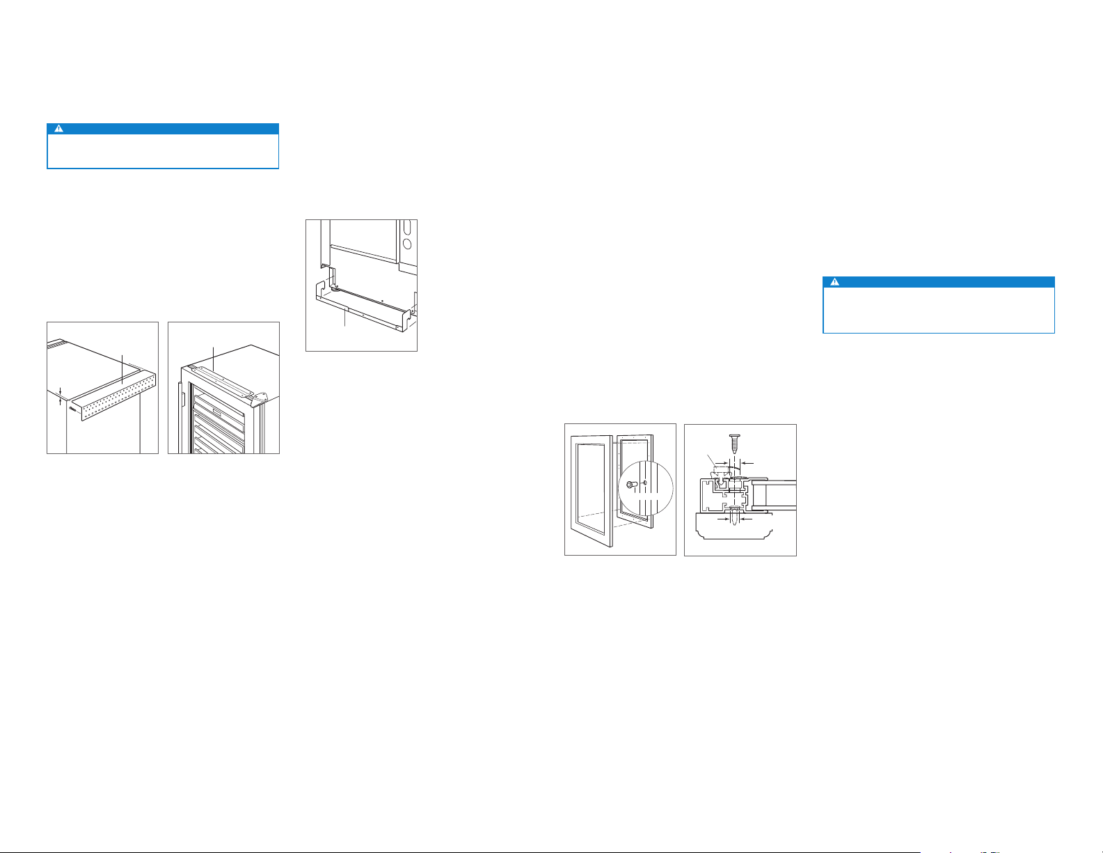
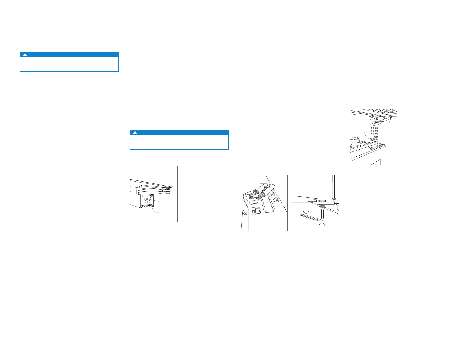
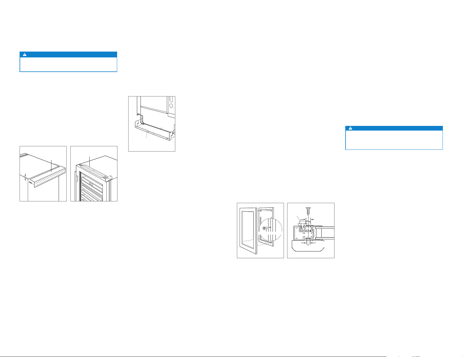
Anti-Tip Bracket
WARNING
To prevent the unit from tipping forward, the anti-tip
bracket must be installed.
MODEL ICBUW-24
The anti-tip bracket should be attached to the wall behind
the unit with the bracket flange located 6 mm above the top
of the unit. Refer to the illustration below. Failure to properly
position the anti-tip bracket will prevent proper engagement.
For installations that cannot accommodate the anti-tip
bracket, a countertop bracket is provided to secure the unit
to the countertop. Refer to the illustration below.
6 mm
Anti-tip bracket (ICBUW-24). Countertop bracket.
COUNTERTOP
BRACKET
MODEL ICBUW-24FS
The back of the anti-tip bracket must be installed 625 mm
from the front and centered behind the unit. Refer to the
illustration below. Refer to page 10 for wood and concrete
floor applications.
ANTI-TIP BRACKET
Anti-tip bracket (ICBUW-24FS).
Custom Panel
MODEL ICBUW-24
For overlay applications, a custom door panel must be
installed. Panel size is critical for a proper fit. To verify panel
requirements and dimensions, refer to the Sub-Zero design
guide.
Finish all sides of the custom panel. They may be visible
when the door is open or through the glass door.
The custom overlay door panel is attached using screws
provided, through the door frame. Screw locations are
marked on the back of the custom panel using tenon centers inserted into holes of the door frame.
With the unit secured and door closed, hold the custom
panel in desired position on the door. Lightly tap the front
of the panel to locate mounting positions. Remove tenon
centers. Refer to the illustration below.
The door frame has mounting holes to accommodate
Sub-Zero accessory handles. If handle mounting holes are
not utilized, the handle should be attached to the custom
panel prior to mounting. Screw heads may need to be countersunk into the panel for proper alignment.
DOOR
FRAMEPANEL
TENON CENTER
GASKET
11 mm
DIAMETER
6 mm
DIAMETER
GLASS
To mount the custom panel, open the door and use predrilled holes to position the panel. Drive screws into the
panel through black tape on the door frame. Screw holes
are hidden behind the door gasket. Use as many screws as
necessary to secure the custom panel. Refer to the illustration below.
Adjustments can be made to the custom panel with a few
mounting screws in place, but not fully tightened. Once the
proper position is achieved, install and secure all screws.
Cover holes on the inside of the door frame with the cover
patches or plugs provided.
CAUTION
A solid panel cannot be installed over the glass door. A
solid door is available through an authorized Sub-Zero
dealer.
4 | English
Tenon center.
Door frame cross section.
Page 5
MODEL ICBUW-24 / ICBUW-24FS INSTALLATION
Placement
CAUTION
Before moving the unit into position, secure the door
closed and protect any nished ooring.
Use an appliance dolly to move the unit near the opening.
If the unit has been on its back or side, it must stand upright
for a minimum of 24 hours before connecting power.
If the unit will be connected to a home security system, run
lead wires through the compressor compartment prior to
positioning the unit. Once the unit is in position, wiring connection can be completed from the front.
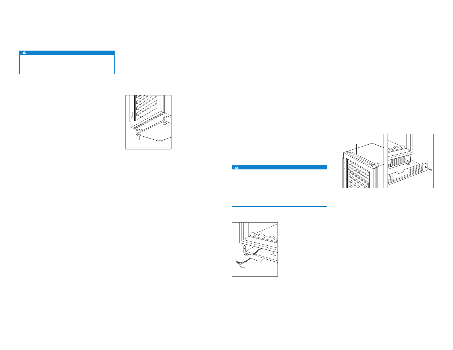
Alignment
LEVELING
Level the unit before sliding it into position. Turn each of the
four leveling legs clockwise to raise the unit and counterclockwise to lower. Refer to the illustration below.
LEVELING LEGS
Leveling.
Completion
Plug the power cord into the grounded (earthed) outlet,
then slide the unit into position. Verify the anti-tip bracket is
properly engaged.
It may be necessary to install the unit 6 mm beyond the
front surface of adjacent cabinetry, to prevent interference
when the door is opened to 145°. Refer to the full-scale
template on page 6.
HOME SECURITY CONNECTION
If the unit will be connected to a home security system,
make connections to the leads shown in the illustration
below. Refer to the following color codes:
• Normally open contacts—white with red stripe wire.
• Normally closed contacts—white with blue stripe wire.
• Common—gray with white stripe wire.
Use the spade terminals or wire nuts provided to make
proper wiring connections.
CAUTION
The alarm circuit in the unit is intended as a lowvoltage, low-current device only. It should not be used
to switch line power. Any unused terminals should be
completely insulated and all wires should be secured
away from conductive or moving components.
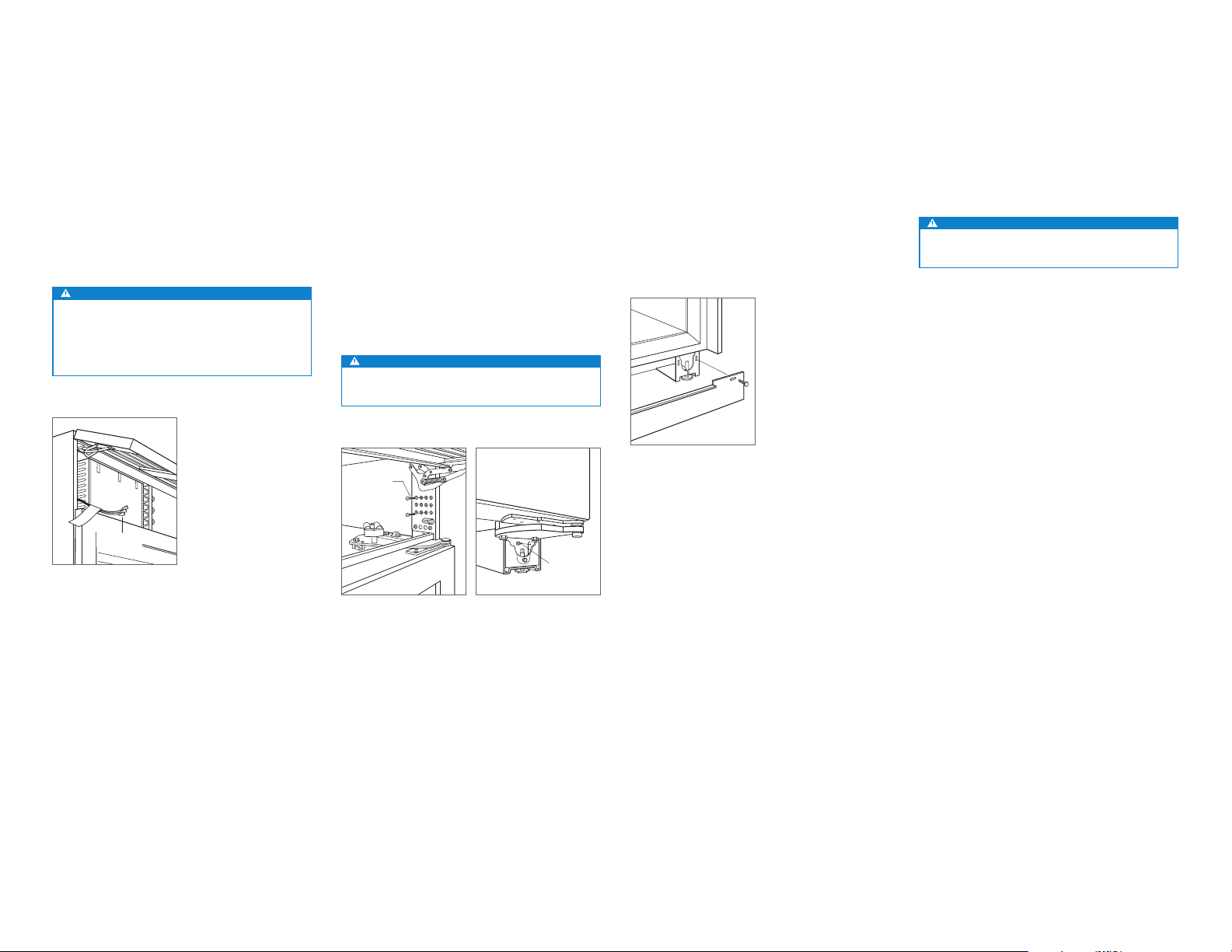
ANCHORING
To anchor, use the countertop bracket provided to secure
the unit to the underside of the countertop. Refer to the
illustration below. If the countertop bracket can not be
utilized, install shims along the top and sides of the unit.
KICKPLATE INSTALLATION
Install the kickplate using the two screws provided. Refer
to the illustration below. The kickplate must be removable
for service. The floor cannot interfere with removal. Do not
cover the louvered section of the kickplate.
COUNTERTOP
BRACKET
KICKPLATE
Anchoring.
Kickplate installation.
HOME SECURITY
LEADS
Home security connection.
subzero.com | 5
Page 6
MODEL ICBUW-24 / ICBUW-24FS INSTALLATION
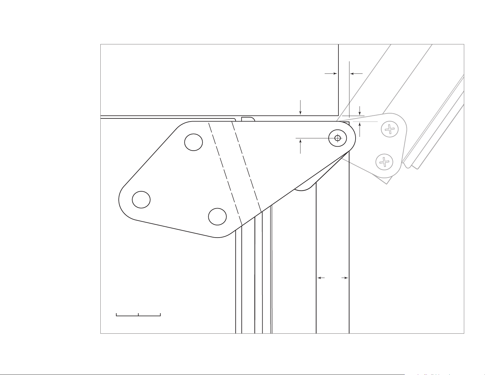
Door Clearance
FULL-SCALE TEMPLATE
To allow for a 145° door opening, the
unit should extend a minimum of 6 mm
beyond the front surface of adjacent
cabinetry. The unit can be installed
flush, however, there is potential for
interference with the panel if the door is
opened past 90°.
ADJACENT
CABINETRY
13 mm
6
mm
3 mm
HINGE AT 145°
OPENING
(DOOR OPENS
PAST 145°)
6 | English
SCALE
145° door opening (top view).
UNDERCOUNTER
UNIT
DOOR CLOSED
19 mm
DOOR PANEL
25 mm0 mm
Page 7
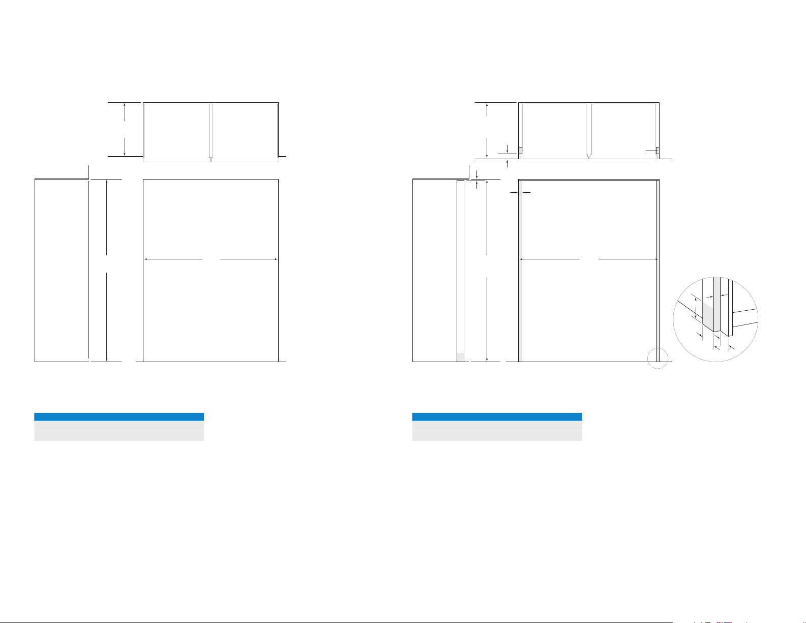
MODEL ICBBW-30 SITE PREPARATION
SIDE
Opening Dimensions
STANDARD INSTALLATION
2127 mm
OPENING
HEIGHT
NOTE: Shaded line represents profile of unit.
610 mm
OPENING
DEPTH
TOP VIEW
W
OPENING WIDTH
FRONT VIEWSIDE VIEW
Opening Dimensions
FLUSH INSET INSTALLATION
665 mm
FLUSH
INSET
DEPTH
56 mm
6 mm
2134 mm
FLUSH
INSET
HEIGHT
VIEW
*76 mm typical depth. Shaded areas will be visible and should be finished to match cabinetry.
NOTE: Shaded line represents profile of unit with 19 mm
32 mm
FLUSH INSET WIDTH
panel.
TOP VIEW
W
FRONT VIEW
FINISHED
CLEATS*
102 mm
32
mm
76
mm*
TYPICAL
mm
56
OPENING WIDTH W
ICBBW-30 749 mm
If two units are installed side by side, refer to page 8.
FLUSH INSET WIDTH W
ICBBW-30 813 mm
Dimensions assume a 19 mm panel thickness. If two units
are installed side by side, refer to page 8.
subzero.com | 7
Page 8

MODEL ICBBW-30 SITE PREPARATION
SIDE
Opening Dimensions
DUAL STANDARD INSTALLATION
610 mm
OPENING
DEPTH
2127 mm
OPENING
HEIGHT
NOTE: Shaded line represents profile of unit.
TOP VIEW
W
OPENING WIDTH
FRONT VIEWSIDE VIEW
Opening Dimensions
DUAL FLUSH INSET INSTALLATION
665 mm
FLUSH
INSET
DEPTH
56 mm
TOP VIEW
6 mm
2134 mm
FLUSH
INSET
HEIGHT
VIEW
*76 mm typical depth. Shaded areas will be visible and should be finished to match cabinetry.
NOTE: Shaded line represents profile of unit with 19 mm
32 mm
FLUSH INSET WIDTH
FRONT VIEW
panel.
FINISHED
CLEATS*
W
32
mm
102 mm
56
76
mm*
TYPICAL
mm
OPENING WIDTH W
ICBBW-30 and 762 mm Built-In Model 1518 mm
ICBBW-30 and 914 mm Built-In Model 1670 mm
8 | English
A dual installation kit will be required for this installation.
FLUSH INSET WIDTH W
ICBBW-30 and 762 mm Built-In Model 1581 mm
ICBBW-30 and 914 mm Built-In Model 1734 mm
Dimensions assume a 19 mm panel thickness. A dual installation kit will be required for this installation.
Page 9
MODEL ICBBW-30 SITE PREPARATION
Dual Installation
If two units are installed side by side, a dual installation kit
may be required. Installations without a custom filler strip
require a dual installation kit. If a dual installation kit is not
specified, a 51 mm filler strip is recommended between
units. Dual installations without a filler strip can only be
accomplished using two units with opposite hinges. Refer to
the illustrations below.
Dual installation kits are available through an authorized
Sub-Zero dealer.
WITHOUT FILLER STRIP
Opposite hinges.
FILLER STRIP
Same side hinges.
Electrical
Installation must comply with all applicable electrical codes
and be properly grounded (earthed).
The electrical supply should be located within the shaded
area shown in the illustration below. A separate circuit, servicing only this appliance is required. A ground fault circuit
interrupter (GFCI) is not recommended and may cause interruption of operation.
ELECTRICAL REQUIREMENTS
Power Supply 220-240 V AC, 50/60 Hz
Circuit Breaker 10 amp
Receptacle grounding-type (earthed)
CAUTION
The outlet must be checked by a qualied electrician to
be sure that it is wired with the correct polarity. Verify
that the outlet is properly grounded (earthed).
178
E
mm
152
mm
1918 mm
FROM FLOOR
RIGHT SIDE
OF OPENING
Electrical supply location.
Electrical
Shock
Hazard
Plug power cord directly into a properly
grounded (earthed) outlet.
Do not defeat the grounding (earthing)
nature of the plug.
Do not use adapter or extension cord.
Failure to follow these instructions could
cause serious injury or death.
See installation instructions
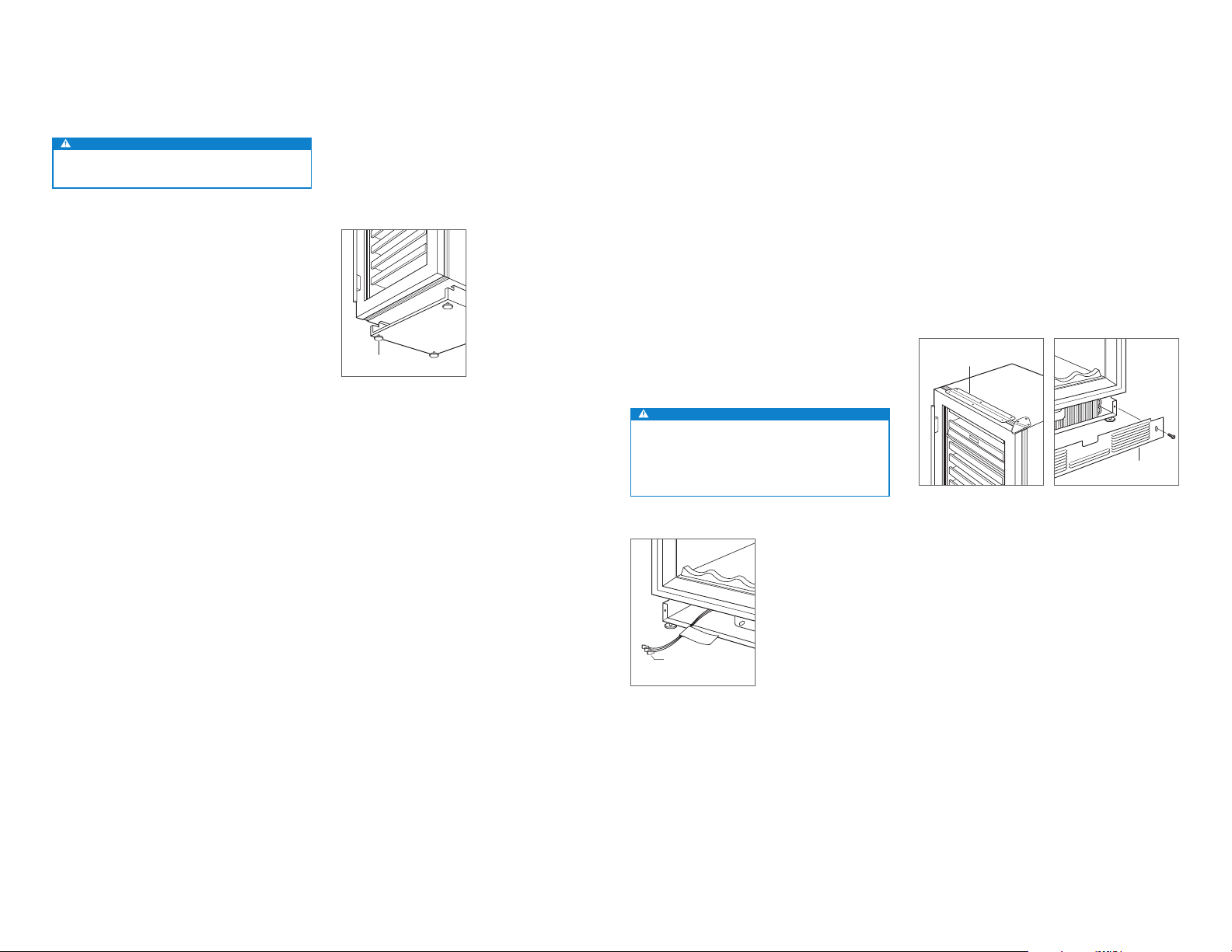
Preparation
Uncrate the unit and inspect for damage. Remove the wood
base and discard shipping bolts and brackets. Remove and
recycle packing materials. Do not discard the kickplate, antitip brackets and hardware.
Completely retract the front leveling legs to allow the unit to
be moved into position. The front and rear leveling legs can
be adjusted from the front once the unit is in position.
Remove the drain pan to avoid damage, and allow for
proper appliance dolly placement.
The grille assembly should be removed prior to moving the
unit. To remove, pull out on the bottom edge of the grille and
rotate upward. Loosen the two back grille mounting screws
and remove the two front grille mounting screws. With the
grille held firmly, pull forward to remove. Refer to the illustrations below.
GRILLE
ADJUSTMENT
FRONT
GRILLE SCREW
SCREWS
Grille removal.
BACK GRILLE
SCREW
Grille mounting screws.
subzero.com | 9
Page 10
MODEL ICBBW-30 INSTALLATION
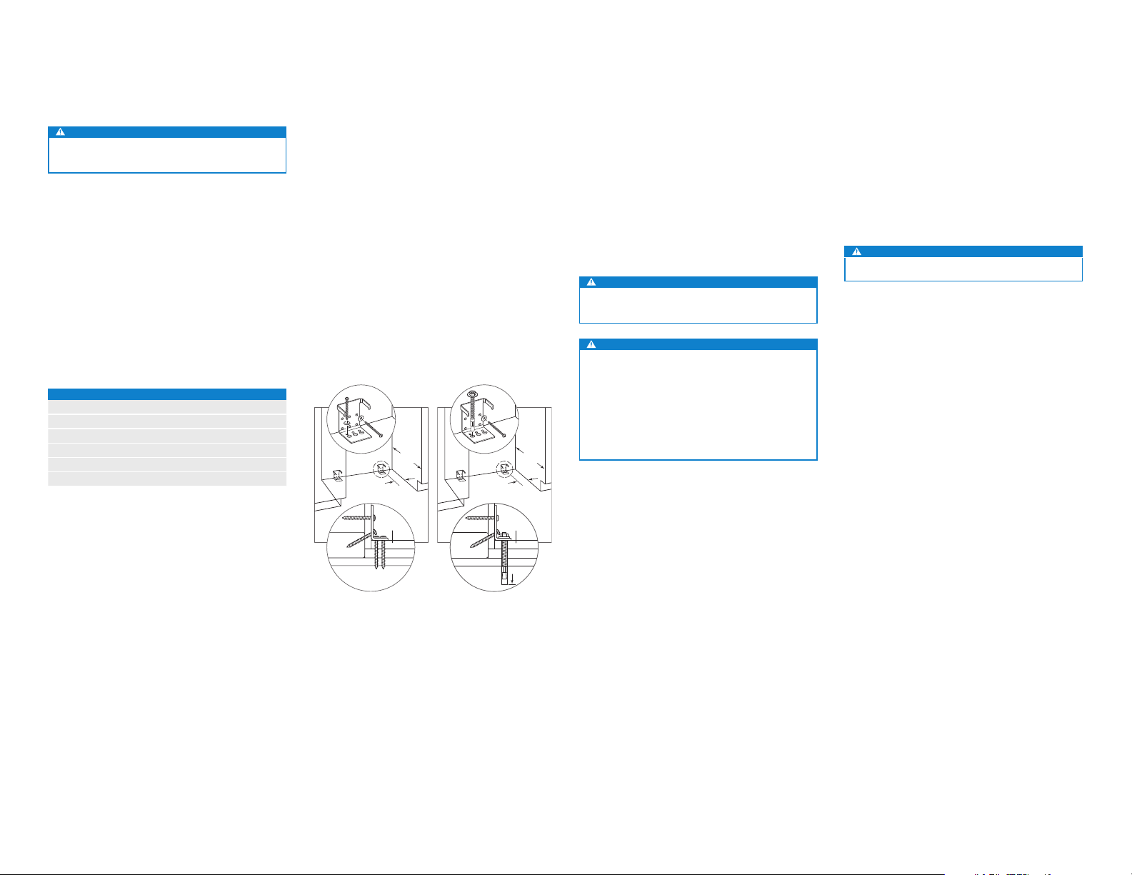
Anti-Tip Bracket
WARNING
To prevent the unit from tipping forward, the anti-tip
brackets must be installed.
The two anti-tip brackets must be installed exactly 610 mm
from the front of the opening to the back of the brackets
and a minimum of 102 mm from the sides of the opening.
This depth will increase to 665 mm for a flush inset installation, based on 19 mm thick panels. Failure to properly position the anti-tip brackets will prevent proper engagement.
Use all anti-tip bracket hardware as instructed for wood or
concrete floors.
IMPORTANT NOTE: For wood or concrete floor applications,
if the #12 screws do not hit a wall stud or wall plate, use the
#8 screws and #12 washers with the wall anchors.
IMPORTANT NOTE: In some installations the subflooring or
finished floor may necessitate angling the screws used to
fasten the anti-tip brackets to the back wall.
ANTI-TIP HARDWARE
2 Anti-tip brackets
12 #12 x 64 mm pan head screws
3
/8"–16 x 95 mm wedge anchors
4
12 #12 flat washers
4 #8–18 x 32 mm truss head screws
4 Nylon Zip-it
®
wall anchors
WOOD FLOOR
After properly locating the anti-tip brackets in the opening,
drill pilot holes 5 mm diameter maximum in the wall studs or
wall plate. Use the #12 screws and washers to secure the
brackets. Verify the screws penetrate through the flooring
material and into wall studs or wall plate a minimum of 19
mm. Refer to the illustration below.
CONCRETE FLOOR
After properly locating the anti-tip brackets in the opening,
drill pilot holes 5 mm diameter maximum in the wall studs
or wall plate. Drill 10 mm diameter holes into the concrete a
minimum of 38 mm deep. Use the #12 screws and washers
to secure the brackets to the wall, and use the
3
/8" wedge
anchors to secure the brackets to the floor. Verify the screws
penetrate wall studs or wall plate a minimum of 19 mm.
Refer to the illustration below.
102 mm
FINISHED
FLOORING
610
mm
MIN
102 mm
FINISHED
FINISHED
FLOORING
FLOORING
610
mm
MIN
CONCRETE WEDGE ANCHOR INSTALLATION
1 Drill a 10 mm diameter hole any depth exceeding the
minimum embedment. Clean the hole or drill additional
depth to accommodate drill fines.
2 Assemble the washer and nut flush with the end of
anchor to protect threads. Drive the anchor through the
material to be fastened until the washer is flush with the
surface material.
3 Expand the anchor by tightening the nut 3–5 turns past
hand-tight position or to 34 newton-meters of torque.
WARNING
Verify there are no electrical wires or plumbing in the
area which the screws could penetrate.
CAUTION
Always wear safety glasses and use other necessary
protective devices or apparel when installing or working
with anchors.
Anchors are not recommended for use in lightweight
masonry material such as block or brick, or for use in
new concrete which has not had sufcient time to cure.
The use of core drills is not recommended to drill holes
for the anchors.
Custom Panels
For overlay and flush inset applications, custom door and
grille panels must be installed. Panel size is critical for a
proper fit. To verify panel requirements and dimensions,
refer to the Sub-Zero design guide.
IMPORTANT NOTE: Flush inset applications require a
minimum 13 mm reveal on all sides.
Finish all sides of the custom panel. They may be visible
when the door is open or through the glass door.
CAUTION
A solid panel cannot be installed over the glass door.
10 | English
WALL PLATE
SUBFLOORING
Wood oor.
WOOD FLOOR
WALL PLATE
WALL PLATE
SUBFLOORING
SUBFLOORING
CONCRETE
CONCRETE
FLOOR
FLOOR
Concrete oor.
11/2"
38 mm
min
MIN
(38)
Page 11
MODEL ICBBW-30 INSTALLATION
2134
mm
610 mm
OPTIONAL
TOE KICK
CUT-OUT
102 mm
48 mm
25 mm
ROUT TO
3 mm
FRONT
OF SIDE
PANEL
67 mm
MAIN
FRAME
SIDE PANEL
ROUTING
25 mm
48 mm
3 mm
13 mm
Panel Installation
DOOR PANEL
To install the custom door panel, remove the handle side
trim molding. Insert a screwdriver tip into the top corner slot
on the handle side and pop out the trim. Remove the screws
and frame. Refer to the illustration below.
The door has a 6 mm frame for the custom panel to slide
into. If the panel is thicker than a 6 mm, rout an edge around
the panel or mount the panel on a sheet of 6 mm thick
material, then insert into the frame.
Door side trim.
A 3 mm space is required between the backer panel and the
custom panel to allow the panel to slide into the door frame.
Refer to the illustrations below for critical dimensions.
Install handle hardware before inserting the panel. Large
D-style handles are recommend rather than knobs. Screw
heads must be countersunk into the panel.
Slide the panel into the frame.
To reinstall the door trim molding, insert the top of the trim
into grooves at the top of the door and work downward,
snapping the trim into clips on the door frame.
SPACER PANEL
CUSTOM PANEL
BACKER PANEL
TRIM
8 mm min
3 mm (OVERLAY)
Panel assembly cross section
(overlay).
CUSTOM
PANEL
19
mm
typical
Panel assembly rear view.
3 mm
SPACER
PANEL
BACKER
PANEL
6 mm
GRILLE PANEL
Remove the bottom grille frame by extracting the lower
two corner screws from each side of the grille assembly.
Refer to the illustration below.
With the bottom section removed, slide the custom grille
panel into the frame. If the panel is thinner than 6 mm, a
filler material will need to be installed to achieve a proper
fit. Once the panel is installed, reattach the bottom grille
frame by sliding the corner brackets back into position, then
reinstall the four corner screws.
BOTTOM
GRILLE
FRAME
Grille frame assembly.
SIDE PANEL
When installing a custom side panel, an accessory kit is
required and is available through an authorized Sub-Zero
dealer. Stainless steel and white enamel side panels are also
available from an authorized Sub-Zero dealer.
IMPORTANT NOTE: The use of side panels may change the
width of the opening.
A custom side panel must be a minimum of 610 mm deep
and 13 mm thick. Routing will be necessary for the side
panel to fit flush against the side of the unit. Refer to the
illustrations below.
IMPORTANT NOTE: The height of the side panel will vary
with the height of the grille. Verify the finished height before
modifying panels.
Side panel dimensions.
Routing detail.
subzero.com | 11
Page 12
MODEL ICBBW-30 INSTALLATION
Placement
CAUTION
Before moving the unit into position, secure the door
closed and protect any nished ooring.
Use an appliance dolly to move the unit near the opening.
If the unit has been on its back or side, it must stand upright
for a minimum of 24 hours before connecting power.
If the unit will be connected to a home security system, run
lead wires through the compressor compartment prior to
positioning the unit. Refer to page 13. Once the unit is in
position, wiring connection can be completed from the front.
Plug the power cord into the grounded (earthed) outlet, then
roll the unit into position. Verify the anti-tip brackets are
properly engaged.
IMPORTANT NOTE: If used, side panels will need to be
installed before the unit is placed in its final position.
Alignment
LEVELING
Once the unit is in position, turn the front leveling legs
clockwise to adjust the height. The rear height adjustment
can be made from the front of the roller base. Using a
socket, turn the
3
/8" hex bolt clockwise to raise the unit or
counterclockwise to lower. Use the lowest torque setting
when using a power drill. Do not turn the rear leveling legs
by hand. Refer to the illustration below.
When the unit is properly leveled, door adjustments are less
likely to be necessary.
IMPORTANT NOTE: Level the unit to the floor, not sur-
rounding cabinetry. This could affect the operation of the
unit, such as door closing.
WARNING
To reduce the possibility of the unit tipping forward, the
front leveling legs must be in contact with the oor.
FRONT
LEVELING LEG
REAR
ADJUSTMENT
Leveling.
3
/8"
DOOR ADJUSTMENT
The door can be adjusted in and out, side to side tilt and up
and down.
To make adjustments, slightly loosening the two upper hinge
bolts on the upper hinge plate using a
1
/2" wrench. Refer to
the illustration below.
5
In and out adjustment | For a left-hinge door, using a
/32"
allen wrench, turn the adjustment bolt clockwise to bring
the handle side of the door inward, and counterclockwise
to move the handle side outward. Reverse directions for a
right-hinge door.
Side to side tilt adjustment | For a left-hinge door, using a
3
/8" wrench, turn the adjustment bolt clockwise to raise the
handle side of the door, and counterclockwise to lower the
handle side. Reverse directions for a right-hinge door.
Up and down adjustment | For a left-hinge door, using a
1
/4" allen wrench, turn the adjustment bolt clockwise to raise
the door and counterclockwise to lower. Refer to the illustration below. Reverse directions for a right-hinge door.
UPPER
HINGE BOLTS
IN-AND-OUT
ADJUSTMENT
SIDE-TO-SIDE
TILT ADJUSTMENT
Door adjustment bolts.
Up and down door adjustment.
Completion
GRILLE INSTALLATION
Install the grille assembly and check for proper fit. The grille
is designed to rest on the upper door hinge to minimize the
reveal between the top of the door and bottom of the grille.
To eliminate interference, the grille height can be adjusted.
Loosen the four grille adjustment screws (two on each side)
and adjust the grille height as needed. Refer to the illustration below.
GRILLE
BACK GRILLE
SCREW
Grille height adjustment.
ADJUSTMENT
FRONT
GRILLE SCREW
SCREWS
12 | English
Page 13
MODEL ICBBW-30 INSTALLATION
Completion
HOME SECURITY CONNECTION
If the unit will be connected to a home security system,
make connections to the leads shown in the illustration
below. Refer to the following color codes:
• Normally open contacts—white with red stripe wire.
• Normally closed contacts—white with blue stripe wire.
• Common—gray with white stripe wire.
Use the spade terminals or wire nuts provided to make
proper wiring connections.
CAUTION
The alarm circuit in the unit is intended as a lowvoltage, low-current device only. It should not be used
to switch line power. Any unused terminals should be
completely insulated and all wires should be secured
away from conductive or moving components.
ANCHORING
After the unit has been leveled and door adjustment completed, anchor the unit to the opening to ensure a proper fit
and secure installation.
To anchor the top of the unit, open the grille and install the
screws provided, through the grille frame into cabinetry.
There are several hole locations. Refer to the illustration
below. Check for proper door clearance by opening the
door.
To anchor the bottom of the unit, drive a screw through the
side hole inside each roller base assembly. The screw will
need to go in at an angle to attach properly. Refer to the
illustration below. Additional material may be needed behind
the cleat to ensure sufficient anchoring.
CAUTION
If the screws provided are not suitable for the installation, use adequate screws.
KICKPLATE INSTALLATION
Reinstall the drain pan and verify it is in the proper position.
Install the kickplate using screws to attach it to brackets on
the inside of each roller base. Refer to the illustration below.
The kickplate must be removable for service. The floor
cannot interfere with removal. Refer to the label mounted on
the kickplate support for height clearance.
Turn power on by touching POWER on the control panel.
90° DOOR STOP
The door opens to 110°. A 90° door stop is provided with
the unit (located behind the grille). Additional 90° door stop
kits are available through an authorized Sub-Zero dealer.
WARNING
Follow all local laws when storing, recycling or discarding unused refrigerators and freezers.
HOME SECURITY
LEADS
Home security connection.
Kickplate installation.
ANCHORING
SCREWS
Top anchoring.
Bottom anchoring.
ANCHORING
SCREW
Sub-Zero, Sub-Zero & Design, Dual Refrigeration, The Living Kitchen, Great American Kitchens The Fine Art of Kitchen Design, and Ingredients are registered trademarks and
service marks of Sub-Zero, Inc. Wolf, Wolf & Design, Wolf Gourmet, W & Design and the color red as applied to knobs are registered trademarks and service marks of Wolf Appli
ance, Inc. (collectively, the “Company Marks.”) All other trademarks or registered trademarks are property of their respective owners in the United States and other countries.
-
subzero.com | 13
Page 14
CONSERVADORES DE VINO
Contenido
2 Conservador de vino
3 Preparación del sitio del modelo ICBUW-24 /
ICBUW-24FS
4 Instalación del modelo ICBUW-24 / ICBUW-24FS
7 Preparación del sitio del modelo ICBBW-30
10 Instalación del modelo ICBBW-30
Las características y especificaciones están sujetas a cambios sin previo aviso.
Nota importante:
Para garantizar que este producto se instala y funciona de
la forma más eficaz y segura posible, tenga en cuenta la
información que se destaca en esta guía:
NOTA IMPORTANTE se utiliza para resaltar información que
resulta especialmente importante.
PRECAUCIÓN indica una situación en la que se pueden
sufrir heridas leves o provocar daños al producto si no se
siguen las instrucciones.
AVISO indica el peligro de que se produzcan heridas graves
o incluso la muerte si no se respetan las precauciones.
NOTA IMPORTANTE: conserve estas instrucciones para el
inspector eléctrico local.
Información sobre el producto
En la placa de datos del producto encontrará información
importante, incluyendo el modelo y el número de serie. La
placa de datos está ubicada en la parte inferior izquierda del
panel de control. Observe las siguientes ilustraciones.
Si necesita recurrir a un servicio técnico, póngase en contacto con un servicio de Sub-Zero certificado con el modelo
y el número de serie.
PLACA DE DATOS
PLACA DE DATOS
Modelos ICBUW-24 y
ICBUW-24FS.
Modelo ICBBW-30.
Herramientas y materiales
• Destornilladores: estándar, Phillips y Torx.
• Taladro.
• Brocas (se necesitarán brocas de mampostería para la
instalación en hormigón).
• Juego de llaves y llaves de vaso estándar.
• Niveles de 0,6 m y 1,2 m.
• Material para proteger la casa, el suelo y los armarios de
cocina durante la instalación.
2 | Español
Page 15
PREPARACIÓN DEL SITIO DEL MODELO ICBUW-24 / ICBUW-24FS
Medidas de la cavidad
MODELO ICBUW-24
610 mm
DE PROFUNDIDAD
DE LA CAVIDAD
VISTA SUPERIOR
876 mm
ALTURA DE
LA CAVIDAD
VISTA LATERAL VISTA FRONTAL
ANCHURA DE LA CAVIDAD Anch.
ICBUW-24 610 mm
Dos modelos de 610 mm* 1.222 mm
*Para esta instalación se necesita un kit de instalación doble.
Anch.
ANCHURA DE LA CAVIDAD
INSTALACIÓN DOBLE
Si va a instalar dos unidades una junto a la otra, puede
que sea necesario un kit de instalación doble. Asimismo,
las instalaciones que no utilicen un embellecedor a medida
necesitarán un kit de instalación doble. Si no se especifica
el kit de instalación doble, se recomienda utilizar un embellecedor de 51 mm entre las unidades. Las instalaciones
dobles sin embellecedor solamente se pueden llevar a cabo
con dos unidades con las bisagras opuestas. Observe las
siguientes ilustraciones.
Podrá encontrar los kits de instalación doble en un distribuidor de Sub-Zero autorizado.
SIN EMBELLECEDOR
Bisagras opuestas.
EMBELLECEDOR
Bisagras al mismo lado.
Potencia
La instalación debe cumplir con todas las normativas eléctricas aplicables y debe estar correctamente conectada a
tierra.
La toma eléctrica debe situarse en el área sombreada en la
siguiente ilustración. Se necesita un circuito independiente
para esta unidad. No se recomienda utilizar un interruptor
de circuito de fallos de toma de tierra (GFCI), ya que puede
interrumpir el funcionamiento de la unidad.
REQUISITOS ELÉCTRICOS
Alimentación eléctrica 220-240 V CA, 50/60 Hz
Magnetotérmico 10 amperios
Enchufe con toma de tierra
PRECAUCIÓN
La toma de corriente debe ser revisada por un electricista cualicado para comprobar que la conexión se ha
realizado con la polaridad correcta. Compruebe que la
toma de corriente está conectada a tierra de manera
correcta.
LADO IZQUIERDO
DE LA CAVIDAD
51
394 mm
mm
E
SUELO
76 mm
Preparación
Para que funcione correctamente, la puerta debe abrirse un
mínimo de 90°. Utilice un embellecedor de al menos 76 mm
cuando instale el aparato en esquinas, con el fin de que se
pueda abrir la puerta a 90°.
Desembale la unidad y compruebe si tiene algún daño o
desperfecto. Quite y recicle los materiales de embalaje. No
tire el zócalo, el soporte antivuelco, las piezas de montaje ni
las patas de nivelación que sujetan la base de madera a la
parte inferior de la unidad.
Ubicación de la alimentación
eléctrica.
Potencia
Descarga
Eléctrica
Enchufe el cable eléctrico directamente en una
toma con conexión a tierra.
No manipule la conexión a tierra del enchufe.
No utilice adaptadores ni alargadores.
Si no sigue estas instrucciones, existe riesgo de
que se produzcan heridas graves o incluso la
muerte.
Ver instrucciones de instalación
subzero.com | 3
Page 16
PREPARACIÓN DEL SITIO DEL MODELO ICBUW-24 / ICBUW-24FS INSTALACIÓN DEL MODELO ICBUW-24 / ICBUW-24FS
Soporte antivuelco
AVISO
Debe instalarse el soporte antivuelco para evitar que la
unidad se incline hacia adelante.
MODELO ICBUW-24
El soporte antivuelco debe quedar fijado a la pared
situada detrás del aparato con la placa del soporte que
se encuentra a 6 mm por encima del aparato. Observe la
siguiente ilustración. Si no coloca bien el soporte antivuelco,
es posible que no quede bien fijado.
En las instalaciones en las que no se pueda colocar el
soporte antivuelvo, se suministra un soporte bajo la encimera para fijar la unidad a la encimera. Observe la siguiente
ilustración.
6 mm
Soporte antivuelco (ICBUW-24). Soporte de encimera.
SOPORTE
DE ENCIMERA
MODELO ICBUW-24FS
La parte trasera del soporte antivuelco debe instalarse a
625 mm de la parte delantera de la unidad y quedar centrada detrás de esta. Observe la siguiente ilustración. Para
aplicaciones en suelos de madera y de hormigón, consulte
la página 10.
SOPORTE ANTIVUELCO
Soporte antivuelco
(ICBUW-24FS).
Panel fabricado a medida
MODELO ICBUW-24
Para aplicaciones revestibles, se debe instalar un panel de
puerta a medida. El tamaño del panel es fundamental para
que se ajuste correctamente. Para comprobar las medidas
y los requisitos del panel, consulte la guía de diseño de
Sub-Zero.
Realice el acabado de todos los lados del panel a medida,
pues son áreas que pueden resultar muy visibles al abrir la
puerta o a través de los cristales.
El panel de puerta revestible a medida se fija con los tornillos suministrados, en el marco de la puerta. Las ubicaciones de los tornillos están marcadas en la parte posterior
del panel a medida con centros de espiga insertados en
orificios del marco de la puerta.
Con la unidad fijada y la puerta cerrada, coloque el panel
a medida en la posición deseada en la puerta. Golpee con
suavidad la parte frontal del panel para localizar las posiciones de montaje. Retire los centros de espiga. Observe la
siguiente ilustración.
El marco de la puerta tiene orificios de montaje para instalar
los tiradores de Sub-Zero que se distribuyen como accesorios. Si no se utilizan los orificios de montaje para los
tiradores, este debe fijarse al panel a medida antes del montaje. Para una alineación correcta, puede que sea necesario
encastar las cabezas de los tornillos en el panel.
PANEL
MARCO DE
LA PUERTA
JUNTA
11 mm
DE DIÁMETRO
Para montar el panel a medida, abra la puerta y utilice los
orificios ya perforados para colocar el panel. Inserte los tornillos en el panel a través de la cinta negra en el marco de la
puerta. Los orificios de los tornillos quedan ocultos detrás
de la junta de la puerta. Utilice todos los tornillos necesarios para sujetar el panel a medida. Observe la siguiente
ilustración.
Es posible realizar ajustes al panel a medida con unos
pocos tornillos de montaje, colocados pero sin estar completamente apretados. Cuando haya alcanzado la posición
adecuada, instale y fije los tornillos.
Cubra los orificios en el interior del marco de la puerta con
las cubiertas o tapones suministrados.
PRECAUCIÓN
No se puede instalar un panel sólido en una puerta de
cristal. La puerta sólida está disponible en los distribuidores de Sub-Zero autorizados.
4 | Español
CENTRO DE ESPIGA
Centro de espiga.
CRISTAL
6 mm
DE DIÁMETRO
Vista transversal del marco de
la puerta.
Page 17
INSTALACIÓN DEL MODELO ICBUW-24 / ICBUW-24FS
Colocación
PRECAUCIÓN
Antes de desplazar la unidad para colocarla en su sitio,
asegúrese de que la puerta esté cerrada y proteja el
acabado del suelo.
Utilice una plataforma rodante para desplazar la unidad
hasta la cavidad.
Si la unidad ha estado boca abajo o sobre uno de los lados,
debe permanecer en posición vertical como mínimo 24
horas antes de conectarla a la alimentación.
Si se desea conectar la unidad al sistema de seguridad de
la casa, es necesario instalar cables por el compartimiento
del compresor antes de colocar la unidad. Una vez colocada la unidad, la conexión de los cables se puede realizar
desde la parte delantera.
Alineación
NIVELADO
Nivele la unidad antes de desplazarla para colocarlo en su
sitio. Gire cada una de las cuatro patas de nivelación en
el sentido de las agujas del reloj para levantar el aparato y
gírelas en sentido contrario para bajar la unidad. Observe la
siguiente ilustración.
PATAS DE
NIVELACIÓN
Nivelado.
Comprobación
Enchufe el cable eléctrico en la toma de conexión a tierra y
deslice la unidad en la posición adecuada. Compruebe que
el soporte antivuelco esté bien fijado.
Puede que sea necesario instalar la unidad de forma que
sobresalga 6 mm de la superficie frontal de los muebles
circundantes, para evitar la interferencia cuando la puerta
se abre a 145º. Consulte la plantilla a escala real de la
página6.
CONEXIÓN AL SISTEMA DE SEGURIDAD DE LA CASA
Si se desea conectar la unidad al sistema de seguridad de
la casa, conecte los cables conforme a la siguiente ilustración. Consulte los siguientes códigos de color:
• Contactos que suelen estar abiertos: cable blanco con
raya roja.
• Contactos que suelen estar cerrados: cable blanco con
raya azul.
• Común: cable gris con raya blanca.
Utilice los terminales en horquilla o las tuercas incluidas
para realizar las conexiones de cables correctamente.
PRECAUCIÓN
El circuito de alarma en el aparato solo constituye
un dispositivo de bajo voltaje y corriente débil. No se
debe utilizar para encender o apagar la conexión de
la línea. Todos los terminales sin utilizar deben quedar
aislados por completo y todos los cables deben
quedar jados lejos de componentes de conducción o
desplazamiento.
ANCLAJE
Para el anclaje, utilice el soporte de encimera suministrado para fijar la unidad a la parte inferior de la encimera.
Observe la siguiente ilustración. Si el soporte de encimera
no se puede utilizar, instale chapas a lo largo de los lados y
la parte superior de la unidad.
INSTALACIÓN DEL ZÓCALO
Instale el zócalo utilizando los dos tornillos suministrados.
Observe la siguiente ilustración. El zócalo debe ser extraíble
para permitir sacarlo en caso de avería. El suelo no puede
ser un impedimento para llevar a cabo esta operación. No
cubra la parte tipo persiana del zócalo.
SOPORTE
DE ENCIMERA
ZÓCALO
Anclaje.
Instalación del zócalo.
CABLES DEL SISTEMA
DE SEGURIDAD
DE LA CASA
Conexión al sistema de seguridad de la casa.
subzero.com | 5
Page 18

INSTALACIÓN DEL MODELO ICBUW-24 / ICBUW-24FS
Margen de apertura de la puerta
PLANTILLA A ESCALA REAL
Para permitir una apertura de la puerta de
145º, la unidad debe sobresalir un mínimo
de 6 mm de la superficie frontal de los
muebles circundantes. La unidad puede
instalarse empotrada, aunque es posible
que interfiera con el panel si la puerta se
abre más de 90°.
MUEBLES
ADYACENTES
13 mm
6
mm
3 mm
BISAGRA A UNA
APERTURA DE 145º
(LA PUERTA DE
ABRE PASADOS145º)
6 | Español
25 mm0 mm
ESCALA
Apertura de la puerta de 145º (vista superior).
UNIDAD BAJO
LA ENCIMERA
PUERTA CERRADA
19 mm
DE PANEL DE
LA PUERTA
Page 19

PREPARACIÓN DEL SITIO DEL MODELO ICBBW-30
VIST
Medidas de la cavidad
INSTALACIÓN ESTÁNDAR
610 mm
DE PROFUNDIDAD
DE LA CAVIDAD
2127 mm
ALTURA DE
LA CAVIDAD
NOTA: las líneas sombreadas representan el perfil de la unidad.
VISTA SUPERIOR
Anch.
ANCHURA DE LA CAVIDAD
VISTA FRONTALVISTA LATERAL
Medidas de la cavidad
INSTALACIÓN EMPOTRABLE
665 mm
DE
PROFUNDIDAD
EMPOTRABLE
56 mm
6 mm
2134 mm
ALTURA DE
INSTALACIÓN
EMPOTRABLE
A LATERAL
*76 mm de profundidad estándar. las áreas sombreadas serán visibles y deberán acabarse para que coincidan con los muebles.
NOTA: las líneas sombreadas representan el perfil de la unidad con un panel de 19 mm.
32 mm
ANCHURA DE INSTALACIÓN
LISTONES
ACABADOS*
VISTA SUPERIOR
Anch.
EMPOTRABLE
VISTA FRONTAL
102 mm
ESTÁNDAR
mm
mm*
32
56
76
mm
ANCHURA DE LA CAVIDAD Anch.
ICBBW-30 749 mm
Si va a instalar dos unidades una junto a la otra, consulte la
página 8.
ANCHURA DE INSTALACIÓN EMPOTRABLE Anch.
ICBBW-30 813 mm
Las medidas están calculadas con un panel de 19 mm de
grosor. Si va a instalar dos unidades una junto a la otra,
consulte la página 8.
subzero.com | 7
Page 20
PREPARACIÓN DEL SITIO DEL MODELO ICBBW-30
VIST
Medidas de la cavidad
INSTALACIÓN DOBLE ESTÁNDAR
610 mm
DE PROFUNDIDAD
DE LA CAVIDAD
2127 mm
ALTURA DE
LA CAVIDAD
NOTA: las líneas sombreadas representan el perfil de la unidad.
VISTA SUPERIOR
Anch.
ANCHURA DE LA CAVIDAD
VISTA FRONTALVISTA LATERAL
Medidas de la cavidad
INSTALACIÓN DOBLE EMPOTRABLE
665 mm
DE
PROFUNDIDAD
EMPOTRABLE
56 mm
VISTA SUPERIOR
6 mm
2134 mm
ALTURA DE
INSTALACIÓN
EMPOTRABLE
A LATERAL
*76 mm de profundidad estándar. las áreas sombreadas serán visibles y deberán acabarse para que coincidan con los muebles.
NOTA: las líneas sombreadas representan el perfil de la unidad con un panel de 19 mm.
32 mm
ANCHURA DE INSTALACIÓN EMPOTRABLE
Anch.
VISTA FRONTAL
LISTONES
ACABADOS*
102 mm
32
mm
76
mm*
ESTÁNDAR
mm
56
ANCHURA DE LA CAVIDAD Anch.
Modelo empotrable de 762 mm e ICBBW-30 1518 mm
Modelo empotrable de 914 mm e ICBBW-30 1670 mm
8 | Español
Para esta instalación se necesita un kit de instalación doble.
ANCHURA DE INSTALACIÓN EMPOTRABLE Anch.
Modelo empotrable de 762 mm e ICBBW-30 1581 mm
Modelo empotrable de 914 mm e ICBBW-30 1734 mm
Las medidas están calculadas con un panel de 19 mm de
grosor. Para esta instalación se necesita un kit de instalación doble.
Page 21

PREPARACIÓN DEL SITIO DEL MODELO ICBBW-30
Instalación doble
Si va a instalar dos unidades una junto a la otra, puede
que sea necesario un kit de instalación doble. Asimismo,
las instalaciones que no utilicen un embellecedor a medida
necesitarán un kit de instalación doble. Si no se especifica
el kit de instalación doble, se recomienda utilizar un embellecedor de 51 mm entre las unidades. Las instalaciones
dobles sin embellecedor solamente se pueden llevar a cabo
con dos unidades con las bisagras opuestas. Observe las
siguientes ilustraciones.
Podrá encontrar los kits de instalación doble en un distribuidor de Sub-Zero autorizado.
SIN EMBELLECEDOR
Bisagras opuestas.
EMBELLECEDOR
Bisagras al mismo lado.
Potencia
La instalación debe cumplir con todas las normativas eléctricas aplicables y debe estar correctamente conectada a
tierra.
La toma eléctrica debe situarse en el área sombreada en la
siguiente ilustración. Se necesita un circuito independiente
para esta unidad. No se recomienda utilizar un interruptor
de circuito de fallos de toma de tierra (GFCI), ya que puede
interrumpir el funcionamiento de la unidad.
REQUISITOS ELÉCTRICOS
Alimentación eléctrica 220-240 V CA, 50/60 Hz
Magnetotérmico 10 amperios
Enchufe con toma de tierra
PRECAUCIÓN
La toma de corriente debe ser revisada por un electricista cualicado para comprobar que la conexión se ha
realizado con la polaridad correcta. Compruebe que la
toma de corriente está conectada a tierra de manera
correcta.
178
E
mm
152
mm
1918 mm
DESDE EL SUELO
LADO DERECHO
DE LA CAVIDAD
Ubicación de la alimentación
eléctrica.
Potencia
Descarga
Eléctrica
Enchufe el cable eléctrico directamente en una
toma con conexión a tierra.
No manipule la conexión a tierra del enchufe.
No utilice adaptadores ni alargadores.
Si no sigue estas instrucciones, existe riesgo de
que se produzcan heridas graves o incluso la
muerte.
Ver instrucciones de instalación
Preparación
Desembale la unidad y compruebe si tiene algún daño o
desperfecto. Retire la base de madera y extraiga todos los
tornillos y soportes del paquete. Quite y recicle los materiales de embalaje. No tire el zócalo, los soportes antivuelco
ni las piezas de montaje.
Repliegue completamente las patas de nivelación delanteras para permitir que la unidad se pueda colocar en la
posición adecuada. Las patas de nivelación delanteras y
traseras pueden ajustarse desde la parte delantera cuando
la unidad ya esté colocada.
Retire el depósito de desagüe para evitar que se dañe y
para que se pueda colocar bien la plataforma rodante.
Retire la rejilla antes de mover la unidad. Para ello, tire
del borde inferior de la rejilla e incline el marco de la rejilla
hasta sacarlo hacia arriba. Afloje los dos tornillos traseros
de montaje de la rejilla y retire los dos tornillos de montaje
delanteros. Sujete firmemente la rejilla y tire hacia adelante
para extraerla. Observe las siguientes ilustraciones.
TORNILLOS DE
AJUSTE DE
LA REJILLA
TORNILLO DELANTERO
DE LA REJILLA
Extracción de la rejilla.
TORNILLO
TRASERO DE
LA REJILLA
Tornillos de montaje de la rejilla.
subzero.com | 9
Page 22

INSTALACIÓN DEL MODELO ICBBW-30
Soporte antivuelco
AVISO
Deben instalarse soportes antivuelco para evitar que la
unidad se incline hacia adelante.
Los dos soportes antivuelco se deben instalar exactamente
a 610 mm de la parte delantera de la cavidad hasta la parte
trasera de los soportes y con un mínimo de 102 mm desde
los lados de la cavidad. Esta profundidad se incrementará
hasta 665 mm si se trata de una instalación empotrable con
paneles delgados de 19 mm. Si no coloca bien los soportes
antivuelcos, es posible que los soportes no queden bien
fijados.
Utilice todas las piezas del soporte antivuelco tal y como
se indica en las instrucciones para suelos de madera o de
hormigón.
NOTA IMPORTANTE: para aplicaciones en suelos de madera
o de hormigón, en caso de que los tornillos del n.º 12 no
alcancen el montante o la placa de pared, utilice tornillos
del n.º 8 y arandelas del n.º 12 con los anclajes para pared.
NOTA IMPORTANTE: en algunas instalaciones es posible
que debido al tipo de suelo o acabado de éste sea necesario colocar inclinados los tornillos utilizados para sujetar
los soportes antivuelco a la pared trasera.
PIEZAS ANTIVUELCO
2 Soportes antivuelco
12 Tornillos de cabeza plana del n.º 12 (64 mm)
4 Anclajes de expansión de 16 x 95 mm –
12 Arandelas planas del n.º 12
4 Tornillos de cabeza ovalada del n° 8 (18 x 32 mm)
4 Anclajes para pared de nailon Zip-it
3
/8"
®
SUELO DE MADERA
Tras colocar correctamente los soportes antivuelco en la
cavidad, perfore orificios guía de 5 mm de diámetro como
máximo en los montantes de pared o en la placa de pared.
Utilice arandelas y tornillos del n.º 12 para fijar los soportes.
Compruebe que los tornillos penetren en el material del
suelo y en los montantes de pared o en las placas un
mínimo de 19 mm. Consulte la siguiente ilustración.
SUELO DE HORMIGÓN
Tras colocar correctamente los soportes antivuelco en la
cavidad, perfore orificios guía de 5 mm de diámetro como
máximo en los montantes de pared o en la placa de pared.
Realice orificios de 10 mm de diámetro en el hormigón con
una profundidad mínima de 38 mm. Utilice arandelas y tornillos del n.º 12 para fijar los soportes a la pared, y anclajes
de expansión de
3
/8" (9,5 mm) para fijar los soportes al
suelo. Compruebe que los tornillos penetran en los montantes de pared o en las placas un mínimo de 19 mm.
Consulte la siguiente ilustración.
PLACA DE PARED
TIPO DE SUELO
SUELO DE MADERA
Suelo de madera.
102 mm
SUELO
ACABADO
610
mm
MIN
WALL PLATE
PLACA DE PARED
SUBFLOORING
TIPO DE SUELO
CONCRETE
FLOOR
Suelo de hormigón.
102 mm
FINISHED
SUELO
FLOORING
ACABADO
11/2"
38 mm
min
MIN
610
mm
MIN
(38)
INSTALACIÓN DE ANCLAJES DE EXPANSIÓN PARA
HORMIGÓN
1 Haga un agujero de 10 mm de diámetro con una profun-
didad superior al incrustado mínimo. Limpie el orificio o
continúe taladrando para hacer que el orificio sea más
profundo y quepan en él los residuos.
2 Coloque la arandela y la tuerca al nivel del extremo del
anclaje para proteger las roscas. Inserte el anclaje en el
material en el que debe atornillarse hasta que la arandela
quede nivelada con el material de la superficie.
3 Extienda el anclaje mediante una llave que sirva para
apretar la tuerca de 3 a 5 vueltas más de su posición
lograda con el apriete manual o hasta 34 Newton metros
de par.
AVISO
Compruebe que no haya cables eléctricos ni tuberías
en el área en la que se van a introducir los tornillos.
PRECAUCIÓN
Lleve siempre gafas de seguridad y utilice cualquier
otro dispositivo o ropa de protección que sea necesario
cuando esté instalando o trabajando con anclajes.
Se recomienda no utilizar los anclajes en material de
mampostería poco pesado, por ejemplo, bloques o
ladrillos, ni utilizarlo en hormigón fresco que no se haya
secado el tiempo suciente. No se recomienda utilizar
brocas huecas para hacer oricios para los anclajes.
Paneles a medida
En aplicaciones revestibles y empotrables, deben instalarse
paneles de rejilla y puertas a medida. El tamaño del panel
es fundamental para que se ajuste correctamente. Para
comprobar las medidas y los requisitos del panel, consulte
la guía de diseño de Sub-Zero.
NOTA IMPORTANTE: las aplicaciones revestibles necesitan
un margen mínimo de 13mm en todos los lados.
Realice el acabado de todos los lados del panel a medida,
pues son áreas que pueden resultar muy visibles al abrir la
puerta o a través de los cristales.
PRECAUCIÓN
No se puede instalar un panel sólido en una puerta de
cristal.
10 | Español
Page 23

INSTALACIÓN DEL MODELO ICBBW-30
2134
mm
610 mm
CORTE
OPCIONAL PARA
EL RODAPIÉ
102 mm
48 mm
25 mm
FRESAR A
3 mm
67 mm
PARTE DEL
ANTERA
DEL PANEL
LATERAL
MARCO
PRINCIPAL
DISPOSICIÓN DEL
PANEL LATERAL
25 mm
48 mm
3 mm
13 mm
Instalación del panel
PANEL DE PUERTA
Para instalar el panel de puerta a medida, retire la moldura
del borde del lateral del tirador. Introduzca la punta de un
destornillador en la ranura de la esquina superior del lateral
del tirador y extraiga el borde. Retire los tornillos y el marco.
Observe la siguiente ilustración.
La puerta tiene un marco de 6mm para deslizar dentro el
panel a medida. Si el panel posee un grosor inferior a 6mm,
frese el borde del panel o monte el panel en una lámina de
material fino de 6mm, y luego introdúzcalo en el marco.
Borde de la puerta.
Se necesita un espacio de 3 mm entre el panel trasero y
el panel a medida para que el panel pueda deslizarse en
el marco de la puerta. Observe las siguientes ilustraciones
para ver las medidas fundamentales.
Coloque las piezas del tirador antes de insertar el panel. Se
recomienda utilizar tiradores anchos en forma de D en lugar
de pomos. Las cabezas de los tornillos se deben encastar
en el panel.
Deslice el panel en el marco.
Para volver a colocar la moldura del borde de la puerta,
introduzca la parte superior del borde en las ranuras de
la parte superior de la puerta tirando de ellas hacia abajo,
encajándolo en las sujeciones del marco.
PANEL ESPACIADOR
PANEL FABRICADO
A MEDIDA
PANEL TRASERO
JUNTA
8 mm mín.
3 mm (REVESTIBLE)
Vista transversal del conjunto
de panel (revestible).
PANEL FABRICADO
A MEDIDA
19
mm
estándar
Vista trasera del conjunto de
panel.
3 mm
PANEL
ESPACIADOR
PANEL
TRASERO
6 mm
PANEL DE REJILLA
Quite el marco de la rejilla inferior extrayendo los dos tornillos de las esquinas inferiores a cada lado del conjunto de la
rejilla. Observe la siguiente ilustración.
Una vez extraída la sección inferior, deslice el panel de rejilla
a medida en el marco. Si el panel posee menos de 6mm
de grosor, necesitará instalar un material de relleno para
que se ajuste correctamente. Cuando el panel esté instalado, vuelva a fijar el marco inferior de la rejilla deslizando
los soportes de las esquinas a su posición y volviendo a
colocar los cuatro tornillos de los extremos.
MARCO DE
LA REJILLA
INFERIOR
Conjunto del marco de la rejilla.
PANEL LATERAL
En caso de instalar un panel lateral a medida, necesitará un
kit de accesorios, disponible en cualquier distribuidor de
Sub-Zero autorizado. Podrá encontrar los paneles laterales
de acero inoxidable y esmalte blanco en su distribuidor de
Sub-Zero autorizado.
NOTA IMPORTANTE: el uso de paneles laterales puede
afectar a la anchura de la cavidad.
Un panel lateral personalizado debe tener un mínimo de
610 mm de profundidad y 13 mm de grosor. Será necesario
sacarlo un poco para que el panel lateral quede empotrado con el lateral de la unidad. Observe las siguientes
ilustraciones.
NOTA IMPORTANTE: la altura del panel lateral variará en fun-
ción de la altura de la rejilla. Compruebe la altura final antes
de modificar los paneles.
Medidas del panel lateral.
Detalle de disposición.
subzero.com | 11
Page 24

INSTALACIÓN DEL MODELO ICBBW-30
Colocación
PRECAUCIÓN
Antes de desplazar la unidad para colocarla en su sitio,
asegúrese de que la puerta esté cerrada y proteja el
acabado del suelo.
Utilice una plataforma rodante para desplazar la unidad
hasta la cavidad.
Si la unidad ha estado boca abajo o sobre uno de los lados,
debe permanecer en posición vertical como mínimo 24
horas antes de conectarla a la alimentación.
Si se desea conectar la unidad al sistema de seguridad de
la casa, es necesario instalar cables por el compartimiento
del compresor antes de colocar la unidad. Consulte la
página 13. Una vez colocada la unidad, la conexión de los
cables se puede realizar desde la parte delantera.
Enchufe el cable eléctrico en la toma de conexión a tierra y
deslice la unidad en la posición adecuada. Compruebe que
los soportes antivuelcos están bien fijados.
NOTA IMPORTANTE: si se utilizan, los paneles laterales
deben instalarse antes de colocar la unidad en su posición
final.
Alineación
NIVELADO
Una vez que la unidad esté colocada en su sitio, gire las
patas de nivelación delanteras en el sentido de las agujas
del reloj para ajustar la altura. El ajuste de la altura de la
parte trasera se puede realizar desde la parte delantera de
la base de la rueda. Con ayuda de una llave de vaso de
gire el tornillo hexagonal de
3
/8" en el sentido de las agujas
3
del reloj para levantar la unidad y en sentido contrario para
bajarla. Utilice el ajuste de torsión más pequeño si utiliza
un taladro. No gire manualmente las patas de nivelación
trasera. Observe la siguiente ilustración.
Cuando la unidad esté correctamente nivelada, no será tan
necesario realizar los ajustes de las puertas.
NOTA IMPORTANTE: nivele la unidad con el suelo, y no con
los demás muebles. Esto puede afectar al funcionamiento
de la unidad, por ejemplo, es posible que la puerta no se
cierre correctamente.
AVISO
Para evitar que la unidad vuelque hacia delante, las
patas de nivelación delanteras deben llegar hasta el
suelo.
AJUSTE DE LA PUERTA
La puerta puede ajustarse hacia dentro y hacia fuera, inclinación de lado a lado y de arriba a abajo.
Para efectuar ajustes, afloje ligeramente los dos pernos
superiores de las bisagras en la placa de bisagras supe-
/8",
riores con una llave de
1
/2". Observe la siguiente ilustración.
Ajuste hacia dentro y hacia fuera | Para ajustar una puerta
con la bisagra a la izquierda, con ayuda de una llave allen
5
/32", gire el perno en el sentido de las agujas del reloj
de
para que el lado del tirador de la puerta se mueva hacia
dentro, y en sentido contrario para que lo haga hacia fuera.
En caso de que sea una puerta con la bisagra a la derecha,
siga las instrucciones en sentido inverso.
Ajuste de inclinación de lado a lado | Para ajustar una
puerta con la bisagra a la izquierda, con ayuda de una llave
3
/8", gire el perno en el sentido de las agujas del
allen de
reloj para extraer el lado del tirador de la puerta se mueva
hacia arriba, y en sentido contrario para que lo haga hacia
abajo. En caso de que sea una puerta con la bisagra a la
derecha, siga las instrucciones en sentido inverso.
Ajuste hacia arriba y hacia abajo | Para ayudar una puerta
con la bisagra a la izquierda, con ayuda de una llave allen
1
/4", gire el perno en el sentido de las agujas del reloj
de
para levantar la puerta, y en sentido contrario para bajarla.
Observe la siguiente ilustración. En caso de que sea una
puerta con la bisagra a la derecha, siga las instrucciones en
sentido inverso.
Finalización
INSTALACIÓN DE LA REJILLA
Instale el conjunto de la rejilla y compruebe que se ajusta
correctamente. La rejilla está diseñada para que se apoye
sobre la bisagra superior de la puerta con el fin de reducir
al mínimo el margen entre la parte superior de la puerta y la
parte inferior de la rejilla. Para evitar que puedan interferir,
deberá ajustar la altura de la rejilla. Afloje los cuatro tornillos
de ajuste de la rejilla (dos a cada lado) y adapte la altura de
esta según corresponda. Observe la siguiente ilustración.
TORNILLO
TRASERO DE
LA REJILLA
Ajuste de la altura de la rejilla.
TORNILLOS DE
AJUSTE DE
LA REJILLA
TORNILLO DELANTERO
DE LA REJILLA
12 | Español
Nivelado.
PATA DE
NIVELACIÓN
DELANTERA
AJUSTE
TRASERO
PERNOS DE LA
BISAGRA SUPERIOR
AJUSTE DE INCLINACIÓN
Pernos de ajuste de la puerta. Ajuste de la puerta hacia arriba
AJUSTE HACIA
DE LADO A LADO
DENTRO Y
HACIA FUERA
y hacia abajo.
Page 25

INSTALACIÓN DEL MODELO ICBBW-30
Finalización
CONEXIÓN AL SISTEMA DE SEGURIDAD DE LA CASA
Si se desea conectar la unidad al sistema de seguridad de
la casa, conecte los cables conforme a la siguiente ilustración. Consulte los siguientes códigos de color:
• Contactos que suelen estar abiertos: cable blanco con
raya roja.
• Contactos que suelen estar cerrados: cable blanco con
raya azul.
• Común: cable gris con raya blanca.
Utilice los terminales en horquilla o las tuercas incluidas
para realizar las conexiones de cables correctamente.
PRECAUCIÓN
El circuito de alarma en el aparato solo constituye
un dispositivo de bajo voltaje y corriente débil. No se
debe utilizar para encender o apagar la conexión de
la línea. Todos los terminales sin utilizar deben quedar
aislados por completo y todos los cables deben
quedar jados lejos de componentes de conducción o
desplazamiento.
ANCLAJE
Cuando la unidad esté nivelada y se haya ajustado la
puerta, ancle la unidad a la cavidad para garantizar que se
ajusta correctamente y que la instalación es segura.
Para anclar la parte superior de la unidad, abra la rejilla y
coloque los tornillos incluidos a través del marco de la rejilla
hasta que penetren en el mobiliario. Hay varios orificios.
Observe la siguiente ilustración. Compruebe el espacio
adecuado para la apertura de la puerta.
Para anclar la parte inferior de la unidad, coloque un tornillo
en el orificio lateral en el conjunto de la base de cada rueda.
El tornillo se debe colocar en ángulo para que la fijación sea
la correcta. Observe la siguiente ilustración. Es posible que
necesite material adicional por detrás del listón para garantizar que el anclaje sea suficiente.
PRECAUCIÓN
En caso de que los tornillos suministrados no sean
adecuados para la instalación, utilice unos tornillos
adecuados.
INSTALACIÓN DEL ZÓCALO
Vuelva a instalar el depósito de desagüe y compruebe que
está en el lugar adecuado.
Instale el zócalo con tornillos para fijarlo a los soportes
del interior de la base de cada rueda. Observe la siguiente
ilustración. El zócalo debe ser extraíble para permitir sacarlo
en caso de avería. El suelo no puede ser un impedimento
para llevar a cabo esta operación. Consulte la etiqueta que
encontrará en el soporte del zócalo para conocer la separación de la altura.
Encienda la unidad pulsando el botón de “POWER” (encendido) en el panel de control.
TOPE DE PUERTA A 90°
La puerta se abre 110º. Se suministra un tope de puerta a
90º con la unidad (situado detrás de la rejilla). Puede pedir
sistemas de tope de puerta a 90° a través de un distribuidor
autorizado de Sub-Zero.
AVISO
Cumpla con todas las normativas locales para el
almacenamiento, reciclaje o eliminación de frigorícos
y congeladores que no se utilicen.
CABLES DEL SISTEMA DE
SEGURIDAD DE LA CASA
Conexión al sistema de seguridad de la casa.
TORNILLOS
DE ANCLAJE
TORNILLOS
DE ANCLAJE
Anclaje de la parte superior. Anclaje de la parte inferior.
Instalación del zócalo.
Sub-Zero, Sub-Zero & Design, Dual Refrigeration, Constant Care, The Living Kitchen, Great American Kitchens The Fine Art of Kitchen Design, e Ingredients son marcas registradas y
marcas de servicio de Sub-Zero, Inc. Wolf, Wolf & Design, Wolf Gourmet, W & Design y los mandos distintivos de color rojo son marcas registradas y marcas de servicio de Wolf Appliance,
Inc. (en su conjunto, las “Marcas de la Empresa”). Todas las demás marcas o marcas registran son propiedad de sus respectivos propietarios en los Estados Unidos y en otros países.
subzero.com | 13
Page 26

CAVES À VIN
Table des matières
2 Caves à vin
3 Préparation de chantier des modèles ICBUW-24 /
ICBUW-24FS
4 Installation des modèles ICBUW-24 /ICBUW-24FS
7 Préparation de chantier des modèles ICBBW-30
10 Installation des modèles ICBBW-30
Les caractéristiques et spécifications peuvent être modifiées
à tout moment sans préavis.
Remarque importante
Pour garantir une installation de ce produit aussi sûre et efficace que possible, veuillez faire particulièrement attention
aux mentions mises en évidence tout au long de ce guide,
notamment :
REMARQUE IMPORTANTE met l'accent sur un renseigne-
ment particulièrement important.
MISE EN GARDE signale un danger qui pourrait causer une
blessure mineure ou endommager le produit si vous ne
suivez pas les instructions.
AVERTISSEMENT signale un danger qui pourrait causer
des blessures graves voire fatales si vous ne prenez pas
certaines précautions.
REMARQUE IMPORTANTE : Conservez ces instructions pour
l'électricien local chargé des inspections.
Information concernant le produit
Les renseignements importants concernant le produit,
notamment la référence modèle et le numéro de série,
figurent sur la plaque des caractéristiques du produit. La
plaque des caractéristiques se trouve sur le dessous du
panneau de commande, à gauche. Reportez-vous aux illustrations ci-après.
Si vous devez contacter le service après-vente, contactez le
prestataire agréé par l'usine Sub-Zero avec les numéros de
modèle et de série.
PLAQUE DES CARACTÉRISTIQUES
PLAQUE DES
CARACTÉRISTIQUES
Modèles ICBUW-24 et
ICBUW-24FS.
Modèle ICBBW-30.
Outils et matériaux
• Tournevis—normaux, Phillips et Torx.
• Perceuse électrique.
• Mèches (mèches de maçonnerie nécessaires pour l'ins-
tallation dans le béton).
• Jeu de clés et de douilles normales.
• Niveaux de 0,6 m et 1,2 m.
• Matériel pour protéger la maison, le sol et son mobilier
pendant l'installation.
2 | Français
Page 27

MODÈLE ICBUW-24 / PRÉPARATION DE CHANTIER ICBUW-24FS
Cotes d'encastrement
MODÈLE ICBUW-24
610 mm
PROFONDEUR
D'OUVERTURE
VUE EN PLAN
876 mm
HAUTEUR
D'OUVERTURE
VUE LATÉRALE VUE DE FACE
LARGEUR D'OUVERTURE L
ICBUW-24 610 mm
Deux modèles de 610 mm* 1 222 mm
*Il sera nécessaire d’avoir un kit d’installation conjointe pour cette installation.
L
LARGEUR D'OUVERTURE
INSTALLATION CONJOINTE
Si deux appareils sont placés côte à côte, il faudra peut-être
se procurer un kit d'installation conjointe. Les installations
sans filler sur mesure exigent un kit d'installation conjointe.
Si aucun kit d'installation conjointe n'est spécifié, il est
recommandé d'utiliser un filler de 51 mm entre les appareils.
Les installations conjointes sans filler ne sont possibles que
lorsqu'il s'agit de deux appareils dont les charnières sont
opposées. Reportez-vous aux illustrations ci-après.
Ces kits d'installation conjointe sont disponibles chez un
revendeur agréé Sub-Zero.
SANS FILLER
Charnières opposées.
Charnières du même côté.
FILLER
Électricité
L'installation doit se conformer à tous les codes électriques
applicables. Elle doit être correctement mise à la terre.
L'alimentation en électricité doit se trouver dans la zone
ombrée indiquée sur l'illustration ci-dessous. Il est nécessaire d'avoir un circuit indépendant, alimentant uniquement
cet appareil ménager. Il n'est pas recommandé d'avoir
recours à un disjoncteur différentiel (GFCI) qui pourrait provoquer l'interruption du fonctionnement de l'appareil.
CONFIGURATION ÉLECTRIQUE
Alimentation électrique 220-240 V c.a., 50/60 Hz
Disjoncteur 10 A
Prise type mise à la terre
MISE EN GARDE
La prise doit être vériée par un électricien qualié.
Celui-ci doit s'assurer qu'elle est dotée de la polarité
adéquate. Assurez-vous que la prise est correctement
mise à la terre.
CÔTÉ GAUCHE
DE L'OUVERTURE
64
330 mm
mm
6 mm
114
E
mm
SOL
Préparation
Pour fonctionner correctement, l'angle d'ouverture de la
porte doit être de 90 degrés minimum. Dans le cas d'une
installation en coin, prévoyez un filler d'au moins 76 mm
pour que la porte puisse s'ouvrir à 90 degrés.
Dégagez l'appareil du carton et inspectez-le afin de déceler
tout dommage éventuel. Retirez et recyclez les matériaux
d'emballage. Ne jetez pas la plinthe, le support antibasculement, le matériel de fixation, ni les pieds de mise à
niveau qui maintiennent le socle en bois à la partie inférieure
de l'appareil.
Emplacement de l'alimentation
électrique.
Électricité
Danger de
Choc Électrique
Branchez directement le cordon électrique
dans une prise avec mise à la terre adéquate.
N’entravez pas la fonction de mise à la terre
de la prise.
N’utilisez pas d'adaptateur ou de cordon de
rallonge.
Le non-respect de ces instructions pourrait
entraîner des blessures graves voire mortelles.
Voir les instructions d’installation
subzero.com
|
3
Page 28

MODÈLE ICBUW-24 / PRÉPARATION DE CHANTIER ICBUW-24FS INSTALLATION DES MODÈLES ICBUW-24 / ICBUW-24FS
Support antibasculement
AVERTISSEMENT
Le support antibasculement doit être installé pour
empêcher l'appareil de basculer vers l'avant.
MODÈLE ICBUW-24
Le support antibasculement devrait être fixé au mur, derrière
l'appareil, la bride du support se trouvant à 6 mm au-dessus
du dessus de l'appareil. Reportez-vous à l'illustration
ci-après. Si le support antibasculement n'est pas correctement positionné, vous ne pourrez pas bien engager
l'appareil.
Pour les installations qui rendent impossible la fixation du
support antibasculement, un support de plan de travail est
fourni pour fixer l'appareil au plan de travail. Reportez-vous
à l'illustration ci-après.
SUPPORT DE
6 mm
Support antibasculement
(ICBUW-24).
PLAN DE TRAVAIL
Support de plan de travail.
MODÈLE ICBUW-24FS
L'arrière du support antibasculement doit être installé à
625mm mesuré depuis le devant de l'appareil et centré
derrière l'appareil. Reportez-vous à l'illustration ci-après.
Consultez la page 10 pour les installations sur planchers et
sols en béton.
SUPPORT
ANTIBASCULEMENT
Support antibasculement
(ICBUW-24FS).
Panneau sur mesure
MODÈLE ICBUW-24
Pour les installations avec habillage, un panneau de porte
sur mesure doit être installé. Ces dimensions sont essentielles pour que l'installation soit faite correctement. Pour
vérifier les configurations pour les panneaux et les dimensions, consultez le Guide technique Sub-Zero.
Finissez tous les côtés du panneau sur mesure. Ils pourraient être visibles lorsque la porte est ouverte ou par la
porte vitrée.
Le panneau d'habillage de la porte est fixé à l'aide des vis
fournies, par le cadre de la porte. Les emplacements des
vis sont indiqués à l'arrière du panneau sur mesure à l'aide
de centres de tenon insérés dans les trous du cadre de la
porte.
Une fois l'appareil bien fixé et la porte fermée, mettez le
panneau sur mesure à la position désirée sur la porte. Tapez
délicatement sur l'avant du panneau pour identifier les
positions de fixation. Retirez les centres de tenon. Reportez-vous à l'illustration ci-après.
Le cadre de la porte possède des trous de fixation pouvant
accueillir les poignées accessoires Sub-Zero. Si les trous de
fixation de poignée ne servent pas, la poignée doit être fixée
au panneau sur mesure avant de le fixer. Les têtes de vis
devront être fraisées dans le panneau pour obtenir un bon
alignement.
PANNEAU
CADRE DE
PORTE
JOINT
11 mm
DIAMÈTRE
Pour fixer le panneau sur mesure, ouvrez la porte et utilisez
les trous pré-percés pour positionner le panneau. Enfoncez
les vis dans le panneau à travers le ruban noir du cadre de
la porte. Les trous des vis sont dissimulés derrière le joint de
la porte. Utilisez autant de vis que nécessaire pour fixer le
panneau sur mesure. Reportez-vous à l'illustration ci-après.
Les réglages peuvent être faits avec quelques vis de fixation
du panneau sur mesure installées mais pas complètement
serrées. Une fois que la bonne position a été obtenue, installez et serrez toutes les vis.
Recouvrez les trous à l'intérieur du cadre de la porte avec
les pastilles ou les bouchons cache-trou fournis.
MISE EN GARDE
Il est impossible d'installer un panneau massif sur la
porte vitrée. Vous pouvez vous procurer une porte
normale chez un revendeur agréé Sub-Zero.
4 | Français
Centre de tenon.
CENTRE DE
TENON
VITRE
6 mm
DIAMÈTRE
Vue en coupe du cadre de
porte.
Page 29

INSTALLATION DES MODÈLES ICBUW-24 / ICBUW-24FS
Emplacement
MISE EN GARDE
Avant de déplacer l'appareil vers son emplacement
dénitif, maintenez la porte fermée et protégez le plancher ni.
Utilisez un diable spécial appareils ménager pour amener
l'appareil à l'ouverture.
Si l'appareil a été couché sur sa partie arrière ou sur le côté,
il faut le laisser en position verticale pendant au moins 24
heures avant de le brancher à l'alimentation électrique.
Si l'appareil doit être connecté à un système de sécurité
résidentiel, il faut prévoir des câbles de raccordement à
travers le compartiment du compresseur avant de placer
l'appareil. Vous pouvez terminer les connexions de câblage
depuis l'avant une fois que l'appareil est à sa place.
Alignement
MISE À NIVEAU
Mettez l'appareil à niveau avant de le glisser en place.
Tournez chacun des quatre pieds de mise à niveau dans
le sens des aiguilles d'une montre pour soulever l'appareil
ou dans le sens contraire pour l'abaisser. Reportez-vous à
l'illustration ci-après.
PIEDS DE MISE À NIVEAU
Mise à niveau.
Dernières finitions
Branchez le cordon électrique dans la prise avec mise à
la terre et faites glisser l'appareil pour le mettre en place.
Vérifiez que le support antibasculement est correctement
engagé.
Il est possible qu'il faille installer l'appareil à 6 mm au-delà
de la face des meubles adjacents, pour éviter tout contact
lorsque la porte est ouverte à 145 degrés. Reportez-vous au
gabarit échelle 1:1 de la page 6.
CONNEXION AU SYSTÈME DE SÉCURITÉ RÉSIDENTIEL
Si l'appareil doit être connecté à un système de sécurité
résidentiel, faites les connexions aux câbles indiqués sur
l'illustration ci-dessous. Faites référence aux codes couleurs
suivants :
• Contacts normalement ouverts – fil blanc avec rayures
rouges.
• Contacts normalement fermés – fil blanc avec rayures
bleues.
• Commun—fil gris avec rayures blanches.
Utilisez les bornes embrochables ou les capuchons de
connexion pour effectuer les branchements appropriés.
MISE EN GARDE
Le circuit de l'alarme qui se trouve dans l'appareil n'est
qu'un dispositif basse tension à faible courant. Il ne
devrait pas être utilisé pour couper ou établir le courant. Toute borne non utilisée devrait être entièrement
isolée et les ls maintenus à l'écart de tout composant
mobile ou conducteur.
ANCRAGE
Pour l'ancrage, utilisez le support de plan de travail fourni
pour fixer l'appareil au-dessous du plan de travail. Reportez-vous à l'illustration ci-après. S'il est impossible d'utiliser
le support de plan de travail, installez des cales le long de la
partie supérieure et des côtés de l'appareil.
INSTALLATION DE LA PLINTHE
Installez la plinthe à l'aide des deux vis fournies. Reportez-vous à l'illustration ci-après. La plinthe doit être amovible pour effectuer des réparations. Le sol ne doit pas
gêner le retrait. Ne recouvrez pas les registres de la plinthe.
SUPPORT DE
PLAN DE TRAVAIL
PLINTHE
Ancrage.
Installation de la plinthe.
CÂBLES DU SYSTÈME DE
SÉCURITÉ RÉSIDENTIEL
Connexion au système de sécurité résidentiel.
subzero.com
|
5
Page 30

INSTALLATION DES MODÈLES ICBUW-24 / ICBUW-24FS
Dégagement de la porte
GABARIT ÉCHELLE 1:1
Pour que la porte puisse s'ouvrir à
145degrés, l'appareil doit dépasser
d'au moins 6 mm de la face des
meubles adjacents. L'appareil peut être
installé à fleur. Le panneau risque toutefois de gêner l'ouverture de la porte
au-delà d'un angle de 90 degrés.
MEUBLES
ADJACENTS
13 mm
6
mm
3 mm
CHARNIÈRE À
L'OUVERTURE À 145 DEGRÉS
(LA PORTE S'OUVRE
AU-DELÀ DE 145 DEGRÉS)
6 | Français
25 mm0 mm
ÉCHELLE
Ouverture de porte à 145 degrés (vue en plan).
MEUBLE SOUS PLAN
PORTE FERMÉE
PANNEAU
DE PORTE
19 mm
Page 31

PRÉPARATION DE CHANTIER DES MODÈLES ICBBW-30
VUE LA
Cotes d'encastrement
INSTALLATION STANDARD
610 mm
PROFONDEUR
D'OUVERTURE
2 127 mm
HAUTEUR
D'OUVERTURE
REMARQUE : La ligne ombrée représente le contour de l'appareil.
VUE EN PLAN
L
LARGEUR D'OUVERTURE
VUE DE FACEVUE LATÉRALE
Cotes d'encastrement
INSTALLATION AVEC PANNEAU D'AFFLEUREMENT
665 mm
PROFONDEUR
DU PANNEAU
D’AFFLEUREMENT
D’AFFLEUREMENT
TÉRALE
*76 mm profondeur normale. Les zones ombrées sont visibles et doivent être finies pour être assorties aux autres éléments de cuisine.
REMARQUE : La ligne ombrée représente le contour de l'appareil avec un panneau de 19 mm.
6 mm
2 134 mm
HAUTEUR
DU PANNEAU
56 mm
VUE EN PLAN
32 mm
L
LARGEUR DU PANNEAU
D’AFFLEUREMENT
VUE DE FACE
TASSEAUX
FINIS*
102 mm
32
mm
76
mm*
EN GÉNÉRAL
mm
56
LARGEUR D'OUVERTURE L
ICBBW-30 749 mm
Si deux appareils sont installés côte à côte, reportez-vous à
la page 8.
LARGEUR DU PANNEAU D’AFFLEUREMENT L
ICBBW-30 813 mm
Les dimensions présument que le panneau mesure 19 mm
d'épaisseur. Si deux appareils sont installés côte à côte,
reportez-vous à la page 8.
subzero.com
|
7
Page 32

PRÉPARATION DE CHANTIER DES MODÈLES ICBBW-30
VUE LA
Cotes d'encastrement
INSTALLATION CONJOINTE CLASSIQUE
610 mm
PROFONDEUR
D'OUVERTURE
2 127 mm
HAUTEUR
D'OUVERTURE
REMARQUE : La ligne ombrée représente le contour de l'appareil.
VUE EN PLAN
L
LARGEUR D'OUVERTURE
VUE DE FACEVUE LATÉRALE
Cotes d'encastrement
INSTALLATION CONJOINTE AVEC PANNEAU D'AFFLEUREMENT
665 mm
PROFONDEUR
DU PANNEAU
D’AFFLEUREMENT
D’AFFLEUREMENT
TÉRALE
*76 mm profondeur normale. Les zones ombrées sont visibles et doivent être finies pour être assorties aux autres éléments de cuisine.
REMARQUE : La ligne ombrée représente le contour de l'appareil avec un panneau de 19 mm.
6 mm
2 134 mm
HAUTEUR
DU PANNEAU
56 mm
32 mm
VUE EN PLAN
L
LARGEUR DU PANNEAU
D’AFFLEUREMENT
VUE DE FACE
TASSEAUX
FINIS*
102 mm
32
mm
76
mm*
EN GÉNÉRAL
mm
56
LARGEUR D'OUVERTURE L
ICBBW-30 et modèle Built-in 762 mm 1 518 mm
ICBBW-30 et modèle Built-in 914 mm 1 670 mm
8 | Français
Il sera nécessaire d'avoir un kit d'installation conjointe pour
cette installation.
LARGEUR DU PANNEAU D’AFFLEUREMENT L
ICBBW-30 et modèle Built-in 762 mm 1 581 mm
ICBBW-30 et modèle Built-in 914 mm 1 734 mm
Les dimensions présument que le panneau mesure 19 mm
d'épaisseur. Il sera nécessaire d'avoir un kit d'installation
conjointe pour cette installation.
Page 33

PRÉPARATION DE CHANTIER DES MODÈLES ICBBW-30
GE
Installation conjointe
Si deux appareils sont placés côte à côte, il faudra peut-être
se procurer un kit d'installation conjointe. Les installations
sans filler sur mesure exigent un kit d'installation conjointe.
Si aucun kit d'installation conjointe n'est spécifié, il est
recommandé d'utiliser un filler de 51 mm entre les appareils.
Les installations conjointes sans filler ne sont possibles que
lorsqu'il s'agit de deux appareils dont les charnières sont
opposées. Reportez-vous aux illustrations ci-après.
Ces kits d'installation conjointe sont disponibles chez un
revendeur agréé Sub-Zero.
SANS FILLER
Charnières opposées.
Charnières du même côté.
FILLER
Électricité
L'installation doit se conformer à tous les codes électriques
applicables. Elle doit être correctement mise à la terre.
L'alimentation en électricité doit se trouver dans la zone
ombrée indiquée sur l'illustration ci-dessous. Il est nécessaire d'avoir un circuit indépendant, alimentant uniquement
cet appareil ménager. Il n'est pas recommandé d'avoir
recours à un disjoncteur différentiel (GFCI) qui pourrait provoquer l'interruption du fonctionnement de l'appareil.
CONFIGURATION ÉLECTRIQUE
Alimentation électrique 220-240 V c.a., 50/60 Hz
Disjoncteur 10 A
Prise type mise à la terre
MISE EN GARDE
La prise doit être vériée par un électricien qualié.
Celui-ci doit s'assurer qu'elle est dotée de la polarité
adéquate. Assurez-vous que la prise est correctement
mise à la terre.
178
E
mm
152
mm
1 918 mm
À PARTIR DU SOL
CÔTÉ DROIT DE
L'OUVERTURE
Emplacement de l'alimentation
électrique.
Électricité
Danger de
Choc Électrique
Branchez directement le cordon électrique
dans une prise avec mise à la terre adéquate.
N’entravez pas la fonction de mise à la
terre de la prise.
N’utilisez pas d'adaptateur ou de cordon
de rallonge.
Le non-respect de ces instructions pourrait
entraîner des blessures graves voire mortelles.
Voir les instructions d’installation
Préparation
Dégagez l'appareil du carton et inspectez-le afin de déceler
tout dommage éventuel. Retirez le socle en bois et jetez les
boulons et les supports d'expédition. Retirez et recyclez les
matériaux d'emballage. Ne jetez pas la plinthe, les supports
antibasculement ni le matériel de fixation.
Rentrez complètement les pieds de mise à niveau avant le
temps de mettre l'appareil à l'endroit prévu. Les pieds de
mise à niveau avant et arrière seront ajustés depuis l'avant
une fois que l'appareil sera en place.
Retirez le bac de vidange pour éviter de l'endommager et
faciliter le maniement du diable spécial appareils ménagers.
Il est conseillé de retirer la grille avant de déplacer l'appareil. Pour cela, tirez d'abord sur le bord inférieur de la grille
et faites-la basculer vers le haut. Desserrez les deux vis de
montage arrière de la grille et retirez les deux vis de montage avant. Tirez la grille vers l'avant en la tenant fermement. Reportez-vous aux illustrations ci-après.
VIS DE RÉGLA
VIS AVANT
DE LA GRILLE
DE LA GRILLE
Retrait de la grille.
VIS ARRIÈRE
DE LA GRILLE
Vis de montage de la grille.
subzero.com
|
9
Page 34

INSTALLATION DES MODÈLES ICBBW-30
Support antibasculement
AVERTISSEMENT
Les supports antibasculement doivent être installés
pour empêcher l'appareil de basculer vers l'avant.
Les deux supports antibasculement doivent être installés
à précisément 610 mm (distance mesurée du devant de
l'ouverture à l'arrière des supports) et au moins 102 mm
des côtés de l'ouverture. La distance en profondeur sera de
665mm pour une installation avec panneau d'affleurement
avec des panneaux de 19 mm d'épaisseur. Si les supports
antibasculement ne sont pas correctement positionnés,
vous ne pourrez pas bien engager l'appareil.
Utilisez tous les accessoires de fixation pour les supports
antibasculement conformément aux directives pour les
planchers en bois ou les sols en béton.
REMARQUE IMPORTANTE : Dans le cas de planchers en
bois ou en béton, si les vis n° 12 ne rencontrent pas de
montant mural ni de plaque murale, utilisez les vis n° 8 et les
rondelles n° 12 avec les pièces d'ancrage mural.
REMARQUE IMPORTANTE : Dans le cas de certaines instal-
lations, le plancher brut ou le revêtement de sol nécessite
que les vis utilisées pour fixer les supports antibasculement
au mur arrière soient posées en angle.
QUINCAILLERIE DE FIXATION ANTIBASCULEMENT
2 Supports antibasculement
12 Vis à tête cylindrique bombée n° 12 x 64 mm
4 Cales d'ancrage 9,5 mm – 16 x 95 mm
12 Rondelles plates n° 12
4 Vis à tête bombée n° 8-18 x 32 mm
4 Pièce d'ancrage mural en Nylon Zip-it
®
PLANCHER EN BOIS
Une fois les supports antibasculement placés correctement dans l'ouverture, percez des avant-trous de 5 mm de
diamètre maximum dans les montants de mur ou la plaque
murale. Utilisez les rondelles plates et des vis n° 12 pour
fixer les supports. Assurez-vous que les vis pénètrent dans
le matériau du plancher ainsi que dans les montants muraux
ou la plaque murale sur une profondeur minimale de 19 mm.
Reportez-vous à l'illustration ci-dessous.
SOL EN BÉTON
Une fois les supports antibasculement placés correctement dans l'ouverture, percez des avant-trous de 5 mm de
diamètre maximum dans les montants de mur ou la plaque
murale. Percez des trous de 10 mm de diamètre et au moins
38 mm de profondeur dans le béton. Utilisez les vis et les
rondelles n° 12 pour fixer les supports au mur ; utilisez
les ancrages à cale 9,5 mm pour fixer les supports au sol.
Assurez-vous que les vis pénètrent dans les montants
muraux ou la plaque murale sur une profondeur minimal de
19 mm. Reportez-vous à l'illustration ci-dessous.
610
mm
102 mm
MIN
610
mm
102 mm
MIN
INSTALLATION D'ANCRAGES À CALE POUR SOLS EN
BÉTON
1 Percez un trou de 10 mm de diamètre à une profondeur
excédant l'enfouissement minimum. Nettoyez le trou ou
continuez à percer afin d'enfoncer les mèches fines.
2 Afin de protéger les filets, assemblez la rondelle et
l'écrou à fleur de l'extrémité de la pièce d'ancrage.
Enfoncez l'ancrage dans le matériau à fixer jusqu'à ce
que la rondelle affleure le matériau de surface.
3 Faites ouvrir la pièce d'ancrage en serrant l'écrou de 3
à 5 tours après la position de serrage manuel ou à un
couple de 34 Newton-mètres.
AVERTISSEMENT
Assurez-vous que les vis ne vont pas rencontrer de
ls électriques ni de conduites de plomberie qu'elles
pourraient percer.
MISE EN GARDE
Mettez toujours des lunettes de sécurité et utilisez tout
équipement ou vêtement de protection requis lorsque
vous réalisez une pose ou un travail d'ancrage.
L'utilisation des ancrages n'est pas recommandée avec
les matériaux de maçonnerie légers comme les blocs
en béton ou les briques, ni dans le béton nouvellement
coulé qui n'a pas eu le temps de mûrir. De plus, l'utilisation de forets-aléseurs n'est pas recommandée pour
percer les trous d'ancrage.
Panneaux sur mesure
Dans le cas où l'on utilise des panneaux d'habillage et des
panneaux d'affleurement, il faut installer des portes sur
mesure et des panneaux de grille. Ces dimensions sont
essentielles pour que l'installation soit faite correctement.
Pour vérifier les configurations pour les panneaux et les
dimensions, consultez le Guide technique Sub-Zero.
REMARQUE IMPORTANTE : Les applications à panneaux
d'affleurement exigent un espace d'au moins 13 mm de
chaque côté.
Finissez tous les côtés du panneau sur mesure. Ils pourraient être visibles lorsque la porte est ouverte ou par la
porte vitrée.
MISE EN GARDE
Il est impossible d'installer un panneau massif sur la
porte vitrée.
10 | Français
PLAQUE MURALE
SOUS-PLANCHER
PLANCHER EN BOIS
Plancher en bois.
PLANCHER
FINI
M
N
Sol en béton.
N
INI
11/2"
38 mm
min
MIN
(38)
Page 35

INSTALLATION DES MODÈLES ICBBW-30
général
2134
mm
610 mm
DÉCOUPE
OPTIONNELLE
DE LA PLINTHE
102 mm
48 mm
25 mm
CREUSER
JUSQU'À
3 mm
DEVANT DU
PANNEAU
DE CÔTÉ
67 mm
CADRE
PRINCIPAL
DÉFONCEMENT
DU PANNEAU
DE CÔTÉ
25 mm
48 mm
3 mm
13 mm
Pose des panneaux
PANNEAU DE PORTE
Pour installer le panneau de porte sur mesure, retirez
d'abord la moulure de porte côté poignée. Insérez le bout
d'un tournevis dans la fente du coin supérieur du côté de la
poignée et faites sortir la moulure. Retirez les vis et le cadre.
Reportez-vous à l'illustration ci-après.
La porte est dotée d'un cadre de 6 mm pour accueillir
le panneau sur mesure. Si le panneau fait plus de 6 mm
d'épaisseur, vous pouvez soit défoncer un rebord tout
autour du panneau, soit monter le panneau sur une plaque
de 6 mm d'épaisseur, puis l'insérer dans le cadre.
Il faut prévoir un espace de 3 mm entre le panneau d'appui
et le panneau sur mesure de sorte que le panneau puisse
coulisser facilement dans le cadre de la porte. Reportez-vous aux illustrations ci-après pour prendre connaissance des dimensions importantes.
La poignée doit être posée avant d'insérer le panneau. Nous
recommandons l'utilisation de poignées en « D » plutôt que
de boutons. Fraisez les têtes des vis dans le panneau.
Faites glisser le panneau dans le cadre.
Pour remettre la moulure en place, insérez la partie supérieure de la moulure dans les rainures en haut de la porte et
procédez vers le bas, en enclenchant la moulure dans les
pinces du cadre de la porte.
PANNEAU INTERCALAIRE
PANNEAU SUR MESURE
PANNEAU D'APPUI
MOULURE
PANNEAU
SUR MESURE
PANNEAU
INTERCALAIRE
PANNEAU
D'APPUI
PANNEAU DE GRILLE
Retirez le cadre de la grille inférieure en retirant les deux
vis des coins inférieurs de chaque côté de la grille. Reportez-vous à l'illustration ci-après.
Une fois la partie inférieure retirée, faites glisser le panneau
de grille sur mesure dans le cadre. Si vous utilisez un panneau de moins de 6 mm d'épaisseur, vous devrez prévoir un
filler pour que l'appareil soit bien ajusté. Une fois le panneau posé, fixez à nouveau le cadre de la grille inférieur en
remettant les supports de coin en place, puis en revissant
les quatre vis des coins.
CADRE DE
LA GRILLE
INFÉRIEURE
PANNEAU DE CÔTÉ
Lorsque vous installez un panneau de côté sur mesure, il
vous faut un kit accessoire que vous pouvez vous procurer
chez un revendeur agréé Sub-Zero. Vous pouvez aussi vous
procurer des panneaux de côté en acier inoxydable et en
émail blanc chez un revendeur agréé Sub-Zero.
REMARQUE IMPORTANTE : L'utilisation de panneaux de
côté peut modifier la largeur de l'ouverture.
Le panneau de côté sur mesure devra mesurer au moins
610 mm de profondeur et 13 mm d'épaisseur. Il sera nécessaire de défoncer le panneau pour que le panneau de côté
soit à fleur contre le côté de l'appareil. Reportez-vous aux
illustrations ci-après.
REMARQUE IMPORTANTE : La hauteur hors tout du pan-
neau de côté dépendra de la hauteur de la grille utilisée.
Vérifiez la hauteur finie avant de modifier les panneaux.
Moulure latérale de porte.
Vue en coupe de l'assemblage
des panneaux (d'habillage).
8 mm min
3 mm (HABILLAGE)
19
mm
en
Vue arrière de l'assemblage des
panneaux.
3 mm
6 mm
Cadre de la grille.
Détail de la procédure de
défoncement.
Dimensions des panneaux de
côté.
subzero.com
|
11
Page 36

INSTALLATION DES MODÈLES ICBBW-30
VERS L'INTÉRIEUR
Emplacement
MISE EN GARDE
Avant de déplacer l'appareil vers son emplacement
dénitif, maintenez la porte fermée et protégez le plancher ni.
Utilisez un diable spécial appareils ménager pour amener
l'appareil à l'ouverture.
Si l'appareil a été couché sur sa partie arrière ou sur le côté,
il faut le laisser en position verticale pendant au moins 24
heures avant de le brancher à l'alimentation électrique.
Si l'appareil doit être connecté à un système de sécurité
résidentiel, il faut prévoir des câbles de raccordement à
travers le compartiment du compresseur avant de placer
l'appareil. Reportez-vous à la page 13. Vous pouvez terminer les connexions de câblage depuis l'avant une fois que
l'appareil est à sa place.
Branchez le cordon électrique dans la prise avec mise à la
terre et faites rouler l'appareil pour le mettre en place. Assurez-vous que les supports antibasculement sont correctement engagés.
REMARQUE IMPORTANTE : Les panneaux de côté doivent,
le cas échéant, être posés avant que l'appareil ne soit mis à
son emplacement définitif.
Alignement
MISE À NIVEAU
Une fois que l'appareil est à son emplacement définitif,
tournez les pieds avant de mise à niveau pour régler la hauteur. Le réglage de la hauteur arrière peut s'effectuer à partir
de l'avant du socle à roulettes. Tournez l'écrou hexagonal
de 9,5 mm à l'aide d'une douille de 9,5 mm dans le sens
des aiguilles d'une montre pour soulever l'appareil ou dans
le sens inverse pour l'abaisser. Utilisez le réglage de couple
le plus bas lorsque vous utilisez une perceuse électrique.
Ne tournez pas les pieds de mise à niveau arrière à la main.
Reportez-vous à l'illustration ci-après.
Si l'appareil est correctement mis à niveau, vous ne devriez
pas avoir à ajuster la porte.
REMARQUE IMPORTANTE : Mettez l'appareil à niveau par
rapport au sol et non par rapport aux meubles adjacents.
Cela pourrait entraver le fonctionnement de l'appareil,
notamment lors de la fermeture des portes.
AVERTISSEMENT
Pour minimiser le risque de basculement de l'appareil
vers l'avant, les pieds de mise à niveau avant doivent
être en contact avec le sol.
AJUSTEMENT DES PORTES
La porte peut être ajustée vers l'intérieur ou l'extérieur, sur
les côtés ou vers le haut ou le bas.
Pour cela, desserrez légèrement les deux boulons de charnière supérieurs sur la lame de charnière supérieure à l'aide
d'une clé de 13 mm. Reportez-vous à l'illustration ci-après.
Pour ajuster vers l'intérieur ou vers l'extérieur | pour une
porte ferrée à gauche, tournez, à l'aide d'une clé Allen
5
/32,
le boulon de réglage dans le sens des aiguilles d'une montre
pour déplacer le côté poignée de la porte vers l'intérieur
et dans le sens inverse pour déplacer le côté poignée de
la porte vers l'extérieur. Inversez cette procédure pour une
porte ferrée à droite.
Pour ajuster sur les côtés | pour une porte ferrée à
gauche, tournez, à l'aide d'une clé
3
/8, le boulon de réglage
dans le sens des aiguilles d'une montre pour soulever
le côté poignée de la porte et dans le sens inverse pour
baisser le côté poignée de la porte. Inversez cette procédure pour une porte ferrée à droite.
Pour ajuster vers le haut ou vers le bas | pour une porte
ferrée à gauche, tournez, à l'aide d'une clé Allen
1
/4, le
boulon de réglage dans le sens des aiguilles d'une montre
pour soulever la porte et dans le sens inverse pour la
baisser. Reportez-vous à l'illustration ci-après. Inversez
cette procédure pour une porte ferrée à droite.
BOULONS DE
CHARNIÈRE
SUPÉRIEURS
Dernières finitions
INSTALLATION DE LA GRILLE
Installez la grille et vérifiez que tout est bien ajusté. La grille
a été conçue de façon à reposer sur la charnière supérieure
de porte afin de minimiser l'espace entre le rebord supérieur
de la porte et le rebord inférieur de la grille. Il est possible
d'ajuster la hauteur de la grille afin d'éliminer toute interférence. Le cas échéant, desserrez les quatre vis de réglage
de la grille (deux de chaque côté) et ajustez la hauteur de la
grille. Reportez-vous à l'illustration ci-après.
VIS ARRIÈRE
DE LA GRILLE
Ajustement de la hauteur de la
grille.
VIS DE RÉGLAGE
VIS AVANT
DE LA GRILLE
DE LA GRILLE
12 | Français
Mise à niveau.
PIED DE
MISE À
NIVEAU AVANT
AJUSTEMENT
À L'ARRIÈRE
SUR LES CÔTÉS
Boulons de réglage des portes. Ajustement de la porte vers le
AJUSTEMENT
AJUSTEMENT
OU L'EXTÉRIEUR
haut et vers le bas.
Page 37

INSTALLATION DES MODÈLES ICBBW-30
Dernières finitions
CONNEXION AU SYSTÈME DE SÉCURITÉ RÉSIDENTIEL
Si l'appareil doit être connecté à un système de sécurité
résidentiel, faites les connexions aux câbles indiqués sur
l'illustration ci-dessous. Faites référence aux codes couleurs
suivants :
• Contacts normalement ouverts – fil blanc avec rayures
rouges.
• Contacts normalement fermés – fil blanc avec rayures
bleues.
• Commun—fil gris avec rayures blanches.
Utilisez les bornes embrochables ou les capuchons de
connexion pour effectuer les branchements appropriés.
MISE EN GARDE
Le circuit de l'alarme qui se trouve dans l'appareil n'est
qu'un dispositif basse tension à faible courant. Il ne
devrait pas être utilisé pour couper ou établir le courant. Toute borne non utilisée devrait être entièrement
isolée et les ls maintenus à l'écart de tout composant
mobile ou conducteur.
ANCRAGE
Une fois l'appareil mis à niveau et la porte ajustée, ancrez
l'appareil dans l'ouverture pour garantir que l'appareil s'encastre bien et est bien fixé.
Pour ancrer le dessus de l'appareil, ouvrez la grille et posez
les vis fournies par le cadre de la grille et dans les éléments.
Il y a plusieurs emplacements de trous prévus. Reportez-vous à l'illustration ci-après. Vérifiez que le dégagement
de la porte est correct en ouvrant la porte.
Pour ancrer la partie inférieure de l'appareil, vissez une vis
par le trou latéral à l'intérieur de chaque socle à roulettes.
La vis devrait pénétrer en angle pour une meilleure fixation.
Reportez-vous à l'illustration ci-après. Il faudra peut-être
avoir recours à d'autre matériel derrière le tasseau pour
garantir un ancrage suffisant.
MISE EN GARDE
Si les vis fournies ne sont pas adaptées à votre cas,
utilisez des vis adéquates.
INSTALLATION DE LA PLINTHE
Remettez le bac de vidange et vérifiez qu'il est bien placé.
Installez la plinthe avec des vis pour la fixer aux supports à
l'intérieur de chaque socle à roulettes. Reportez-vous à l'illustration ci-après. La plinthe doit être amovible pour effectuer des réparations. Le sol ne doit pas gêner le retrait. Pour
déterminer le dégagement requis en hauteur, reportez-vous
à l'étiquette apposée sur le support de la plinthe.
Activez l'appareil en effleurant la touche « POWER »
(marche) sur le panneau de commande.
ARRÊT DE PORTE À 90 DEGRÉS
La porte s'ouvre à un angle de 110 degrés. Un arrêt de
porte à 90 degrés est fourni avec l'appareil (situé derrière la
grille). D'autres kits d’arrêt de porte à 90 degrés sont disponibles chez votre revendeur agréé Sub-Zero.
AVERTISSEMENT
Respectez toutes les règlementations locales et régionales pour l'entreposage, le recyclage et la mise au
rebut des réfrigérateurs et des congélateurs mis hors
service.
CÂBLES DU SYSTÈME
DE SÉCURITÉ RÉSIDENTIEL
Connexion au système de sécurité résidentiel.
VIS
D'ANCRAGE
VIS
D'ANCRAGE
Ancrage supérieur.
Ancrage inférieur.
Installation de la plinthe.
Sub-Zero, Sub-Zero & Design, Dual Refrigeration, The Living Kitchen, Great American Kitchens The Fine Art of Kitchen Design et Ingredients sont des marques déposées et des
marques de service de Sub-Zero, Inc. Wolf, Wolf & Design, Wolf Gourmet, W & Design et la couleur rouge comme celle qui est appliquée aux boutons sont des marques déposées et
des marques de service de Wolf Appliance, Inc. (collectivement; les « marques d'entreprise »). Toutes les autres marques de commerce ou marques déposées ont été brevetées par
leurs propriétaires respectifs aux États-Unis ou dans d'autres pays.
subzero.com
|
13
Page 38

CANTINA PER VINI
Indice
2 Cantina per vini
3 Preparazione della sede per i modelli ICBUW-24 /
ICBUW-24FS
4 Installazione dei modelli ICBUW-24 / ICBUW-24FS
7 Preparazione della sede per il modello ICBBW-30
10 Installazione del modello ICBBW-30
Le caratteristiche e le specifiche sono soggette a modifica
in qualsiasi momento senza preavviso.
Nota importante
Per garantire l'installazione e il funzionamento sicuri ed efficienti di questo prodotto, prestare attenzione alle seguenti
informazioni evidenziate nella guida:
NOTA IMPORTANTE evidenzia informazioni di particolare
rilievo.
ATTENZIONE indica una situazione in cui possono verificarsi
lesioni alle persone o danni di lieve entità al prodotto in caso
di mancata osservanza delle istruzioni.
AVVERTENZA indica un rischio che potrebbe causare gravi
lesioni o morte in caso di mancata osservanza delle precauzioni.
NOTA IMPORTANTE: conservare le presenti istruzioni per
eventuali verifiche tecniche.
Informazioni sul prodotto
Sulla targhetta identificativa del prodotto sono riportate
importanti informazioni, inclusi il modello e il numero di
serie. La targhetta identificativa è situata nella parte inferiore
del pannello di controllo, a sinistra. Fare riferimento alle
figure riportate di seguito.
Per l'assistenza, contattare un centro di assistenza autorizzato Sub-Zero e specificare il modello e il numero di serie.
TARGHETTA IDENTIFICATIVA
TARGHETTA
IDENTIFICATIVA
Modelli ICBUW-24 e
ICBUW-24FS.
Modello ICBBW-30.
Attrezzi e materiali
• Cacciaviti—standard, Phillips e Torx.
• Trapano.
• Punte per trapano (per le installazioni su cemento sono
necessarie punte per muratura).
• Set standard brugola e viti.
• Livelli da 0,6 m e 1,2 m.
• Materiale per proteggere la casa, i pavimenti e i mobili
durante l'installazione.
2 | Italiano
Page 39

PREPARAZIONE DELLA SEDE PER I MODELLI ICBUW-24 / ICBUW-24FS
Dimensioni vano incasso
MODELLO ICBUW-24
610 mm
PROFONDITÀ VANO
INCASSO
VISTA DALL'ALTO
876 mm
ALTEZZA VANO
INCASSO
VISTA LATERALE VISTA FRONTALE
LARGHEZZA VANO INCASSO L
ICBUW-24 610 mm
Due modelli da 610 mm* 1.222 mm
*Per questo tipo di installazione è necessario un kit per l’installazione di
modelli afancati.
L
LARGHEZZA VANO
INCASSO
INSTALLAZIONE DOPPIA
Per le installazioni in cui le unità sono affiancate, può essere
necessario un kit per l'installazione doppia. Le installazioni
che non prevedono una basetta di riempimento personalizzata richiedono un kit per l'installazione doppia. Se il kit
per l'installazione doppia non è specificato, tra le unità si
consiglia di inserire una basetta di riempimento da 51 mm.
È possibile eseguire installazioni doppie senza basetta di
riempimento esclusivamente utilizzando due unità dotate
di cerniere opposte. Fare riferimento alle figure riportate di
seguito.
I kit per l'installazione doppia sono disponibili presso i rivenditori Sub-Zero autorizzati.
SENZA DISTANZIALE
Cardini opposti.
DISTANZIALE
Cardini sullo stesso lato.
Alimentazione elettrica
L'installazione deve essere conforme alle normative elettriche vigenti in materia e prevedere un'adeguata linea di
messa a terra.
L'alimentazione elettrica deve trovarsi all'interno dell'area
ombreggiata riportata nella seguente figura. È necessario predisporre un circuito elettrico dedicato per questo
elettrodomestico. Si sconsiglia l'utilizzo di un interruttore
automatico salvavita (GFCI), che potrebbe causare problemi
di funzionamento.
REQUISITI ELETTRICI
Alimentazione 220-240 V c.a., 50/60 Hz
Interruttore circuito 10 A
Presa di corrente con messa a terra
ATTENZIONE
La presa di corrente va controllata da un elettricista
qualicato per accertarsi che sia collegata con la polarità giusta. Controllare che la presa sia dotata di messa
a terra adeguata.
PARTE SINISTRA
DELL'APERTURA
51
394 mm
mm
PAVIMENTO
76 mm
E
Preparazione
Per un utilizzo corretto le porte devono potersi aprire di
almeno 90°. Per installazioni angolari, lasciare una distanza
minima di 76mm affinché la porta si possa aprire di 90°.
Rimuovere l'imballaggio ed escludere la presenza di danni.
Rimuovere e riciclare il materiale di imballaggio. Non gettare
lo zoccolo, la barra antiribaltamento, la minuteria e i piedini
di livellamento che fissano la base in legno alla parte inferiore dell'unità.
Posizionamento alimentazione
elettrica.
Alimentazione Elettrica
Scossa
Elettrica
Collegare il cavo di alimentazione direttamente a
una presa dotata di messa a terra.
Non disattivare la predisposizione per la
messa a terra della spina.
Non utilizzare un riduttore o una prolunga.
La mancata osservanza di queste istruzioni
potrebbe causare gravi lesioni o morte.
Consultare le istruzioni per l'installazione
subzero.com | 3
Page 40

PREPARAZIONE DELLA SEDE PER I MODELLI ICBUW-24 / ICBUW-24FS INSTALLAZIONE DEI MODELLI ICBUW-24 / ICBUW-24FS
Barra antiribaltamento
AVVERTENZA
La barra antiribaltamento va installata per impedire che
l'unità si ribalti in avanti.
MODELLO ICBUW-24
La barra antiribaltamento deve essere fissata alla parete
retrostante con la flangia posizionata 6mm al di sopra
della parte superiore dell'unità. Fare riferimento alla figura
di seguito. Il posizionamento errato della barra antiribaltamento ne impedirebbe l'inserimento appropriato.
Per le installazioni che non possono supportare la barra
antiribaltamento, viene fornita una barra apposita per fissare
l'unità al piano di lavoro. Fare riferimento alla figura di
seguito.
BARRA PER
6 mm
Barra antiribaltamento
(ICBUW-24).
PIANO DI LAVORO
Barra per piano di lavoro.
MODELLO ICBUW-24FS
Il retro della barra antiribaltamento deve essere installato
a 625mm dalla parte frontale e centrato rispetto alla parte
retrostante dell'unità. Fare riferimento alla figura di seguito.
Consultare pagina 10 per le applicazioni su pavimenti di
legno e cemento.
BARRA
ANTIRIBALTAMENTO
Barra antiribaltamento
(ICBUW-24FS).
Pannello personalizzato
MODELLO ICBUW-24
Per applicazioni a sovrapposizione, è necessario installare
pannelli porta personalizzati. Le dimensioni del pannello
sono fondamentali per un corretto montaggio. Per verificare
i requisiti e le dimensioni del pannello, consultare la guida al
design di Sub-Zero.
Rifinire tutte le parti laterali del pannello personalizzato in
quanto possono essere visibili quando la porta è aperta o
attraverso la porta a vetri.
La porta personalizzata per sovrapposizioni viene fissata
con le viti in dotazione, attraverso il telaio della porta. La
posizione delle viti è indicata sul retro del pannello personalizzato attraverso spinotti inseriti nei fori del telaio della
porta.
Con l'unità fissata e la porta chiusa, tenere il pannello personalizzato nella posizione desiderata sulla porta. Battere
leggermente la parte anteriore del pannello per individuare
le posizioni di montaggio. Rimuovere gli spinotti. Fare riferimento alla figura di seguito.
Il telaio della porta è dotato di fori di montaggio per l'installazione delle maniglie Sub-Zero. Se i fori di montaggio delle
maniglie non vengono utilizzati, la maniglia deve essere
fissata al pannello personalizzato prima del montaggio. È
possibile che le teste delle viti debbano essere svasate nel
pannello.
PANNELLO
TELAIO
PORTA
GUARNIZIONE
11 mm
DIAMETRO
Per montare il pannello personalizzato, aprire la porta e
utilizzare i fori pre-tracciati per posizionare il pannello.
Avvitare le viti sul pannello attraverso il nastro nero presente
sul telaio della porta. I fori per le viti sono nascosti dietro
la guarnizione della porta. Usare tutte le viti necessarie per
fissare il pannello personalizzato. Fare riferimento alla figura
di seguito.
Le regolazioni del pannello personalizzato possono essere
eseguite con un paio di viti di montaggio inserite ma non
completamente serrate. Dopo aver definito la posizione
corretta, inserire e fissare tutte le viti.
Coprire i fori all'interno del telaio della porta con i tappi
forniti in dotazione.
ATTENZIONE
Sulla porta di vetro, non è possibile installare un pannello pieno. Le porte piene sono disponibili presso i
rivenditori Sub-Zero autorizzati.
4 | Italiano
Spinotto.
SPINOTTO
VETRO
6 mm
DIAMETRO
Sezione trasversale telaio porta.
Page 41

INSTALLAZIONE DEI MODELLI ICBUW-24 / ICBUW-24FS
Posizionamento
ATTENZIONE
Prima di posizionare l'unità bloccare la porta e proteggere i pavimenti riniti.
Spostare l'unità accanto all'apertura mediante un carrello.
Se l'unità è stata appoggiata su un lato, deve rimanere in
posizione verticale per almeno 24 ore prima di collegare
l'alimentazione.
L'unità sarà collegata al sistema di sicurezza domestico, far
passare i cavi attraverso il vano compressore prima di posizionare l'unità. Quando l'unità è in sede, è possibile eseguire
il cablaggio dalla parte anteriore.
Allineamento
MESSA A LIVELLO
L'unità deve essere messa a livello prima del posizionamento. Ruotare ciascuno dei quattro piedini di livellamento
in senso orario per sollevare l'unità, in senso antiorario per
abbassarla. Fare riferimento alla figura di seguito.
PIEDINI DI
LIVELLAMENTO
Livellamento.
Completamento
Inserire il cavo di alimentazione in una presa dotata di
messa a terra e far scorrere l'unità in posizione. Verificare
che la barra antiribaltamento sia inserita correttamente.
Potrebbe essere necessario installare l'unità 6mm oltre la
superficie anteriore del mobile adiacente, per evitare interferenze quando la porta è aperta a 145°. Fare riferimento al
modello in scala 1:1 a pagina 6.
CABLAGGIO AL SISTEMA DI SICUREZZA DOMESTICO
L'unità sarà collegata al sistema di sicurezza domestico,
eseguire il cablaggio come indicato nella figura riportata di
seguito. Fare riferimento ai seguenti codici colore:
• Contatti normalmente aperti—cavo bianco a strisce
rosse.
• Contatti normalmente chiusi —cavo bianco a strisce blu.
• Comune—cavo bianco a strisce grigie.
Per eseguire correttamente il cablaggio utilizzare i capocorda a forcella o i dadi in dotazione.
ATTENZIONE
Il circuito d'allarme all'interno dell'unità è inteso esclusivamente come dispositivo a basso voltaggio e bassa
corrente e non deve essere utilizzato per accendere
l'alimentazione. Tutti i capocorda inutilizzati vanno
isolati perfettamente e tutti i cavi vanno allontanati dai
componenti conduttivi o mobili.
ANCORAGGIO
Per ancorare l'unità, utilizzare la barra per piano di lavoro
in dotazione e fissare l'unità alla parte inferiore del piano
di lavoro. Fare riferimento alla figura di seguito. Se non è
possibile utilizzare la barra del piano di lavoro, inserire degli
spessori lungo la parte superiore e ai lati dell'unità.
INSTALLAZIONE DELLO ZOCCOLO
Installare lo zoccolo utilizzando le due viti in dotazione.
Fare riferimento alla figura di seguito. Deve essere possibile rimuovere lo zoccolo per interventi di manutenzione. Il
pavimento non deve interferire con la rimozione. Non coprire
la sezione a persiana dello zoccolo.
BARRA PER
PIANO DI LAVORO
ZOCCOLO
Ancoraggio.
Installazione dello zoccolo.
CABLAGGIO AL
SISTEMA DI
SICUREZZA DOMESTICO
Cablaggio al sistema di sicurezza domestico.
subzero.com | 5
Page 42

INSTALLAZIONE DEI MODELLI ICBUW-24 / ICBUW-24FS
Ingombro apertura porta
MODELLO IN SCALA 1:1
Per permettere l'apertura della porta a
145°, l'unità deve sporgere di almeno
6mm oltre la superficie anteriore del
mobile adiacente. L'unità può essere
installata a filo, tuttavia c'è il rischio che
interferisca con il pannello se la porta
viene aperta di oltre 90°.
MOBILI
ADIACENTI
13 mm
6
mm
3 mm
CERNIERA A 145°
DI APERTURA
(LA PORTA SI
APRE OLTRE 145°)
6 | Italiano
25 mm0 mm
SCALA
Apertura porta a 145° (vista dall'alto).
UNITÀ
SOTTOPIANO
SPORTELLO
CHIUSO
19 mm
PANNELLO
PORTA
Page 43

PREPARAZIONE DELLA SEDE PER IL MODELLO ICBBW-30
VISTA LATERALE
Dimensioni vano incasso
INSTALLAZIONE STANDARD
610 mm
PROFONDITÀ VANO
INCASSO
2127 mm
ALTEZZA VANO
INCASSO
NOTA: La linea ombreggiata rappresenta il profilo dell'unità.
VISTA DALL'ALTO
L
LARGHEZZA VANO
INCASSO
VISTA FRONTALEVISTA LATERALE
Dimensioni vano incasso
INSTALLAZIONE A FILO
665 mm
PROFONDITÀ
CON INSERTI
A FILO
56 mm
6 mm
2134 mm
ALTEZZA CON
INSERTI A FILO
*76 mm profondità tipica. Le aree ombreggiate saranno visibili e andranno rifinite in abbinamento all'arredamento.
NOTA: la linea ombreggiata rappresenta il profilo dell'unità con pannello da 19 mm.
32 mm
LARGHEZZA CON INSERTI A FILO
PROFILI DI
TAMPONATURA
FINITI*
VISTA DALL'ALTO
L
VISTA FRONTALE
102 mm
32
mm
76
mm*
TIPICO
mm
56
LARGHEZZA VANO INCASSO L
ICBBW-30 749 mm
Per le installazioni in cui le unità sono parallele, consultare le
istruzioni a pagina 8.
LARGHEZZA CON INSERTI A FILO L
ICBBW-30 813 mm
Le dimensioni presuppongono uno spessore per il pannello
di 19 mm. Per le installazioni in cui le unità sono parallele,
consultare le istruzioni a pagina 8.
subzero.com | 7
Page 44

PREPARAZIONE DELLA SEDE PER IL MODELLO ICBBW-30
VIST
Dimensioni vano incasso
INSTALLAZIONI UNITÀ AFFIANCATE
610 mm
PROFONDITÀ VANO
INCASSO
2127 mm
ALTEZZA VANO
INCASSO
NOTA: la linea ombreggiata rappresenta il profilo dell'unità.
VISTA DALL'ALTO
L
LARGHEZZA VANO
INCASSO
VISTA FRONTALEVISTA LATERALE
Dimensioni vano incasso
INSTALLAZIONE DOPPIA CON INSERTO A FILO
665 mm
PROFONDITÀ
CON INSERTI
A FILO
56 mm
VISTA DALL'ALTO
6 mm
2134 mm
ALTEZZA CON
INSERTI A FILO
A LATERALE
*76 mm profondità tipica. Le aree ombreggiate saranno visibili e andranno rifinite in abbinamento all'arredamento.
NOTA: la linea ombreggiata rappresenta il profilo dell'unità con pannello da 19 mm.
32 mm
LARGHEZZA CON INSERTI A FILO
L
VISTA FRONTALE
PROFILI DI
TAMPONATURA
FINITI*
102 mm
32
mm
76
mm*
TIPICO
mm
56
LARGHEZZA VANO INCASSO L
Modello da incasso ICBBW-30 da 762mm 1518 mm
Modello da incasso ICBBW-30 da 914mm 1670 mm
8 | Italiano
Per questo tipo di installazione è necessario un kit per l'installazione doppia.
LARGHEZZA CON INSERTI A FILO L
Modello da incasso ICBBW-30 da 762mm 1581 mm
Modello da incasso ICBBW-30 da 914mm 1734 mm
Le dimensioni presuppongono uno spessore per il pannello
di 19 mm. Per questo tipo di installazione è necessario un
kit per l'installazione doppia.
Page 45

PREPARAZIONE DELLA SEDE PER IL MODELLO ICBBW-30
Installazione doppia
Per le installazioni in cui le unità sono affiancate, può essere
necessario un kit per l'installazione doppia. Le installazioni
che non prevedono una basetta di riempimento personalizzata richiedono un kit per l'installazione doppia. Se il kit
per l'installazione doppia non è specificato, tra le unità si
consiglia di inserire una basetta di riempimento da 51 mm.
È possibile eseguire installazioni doppie senza basetta di
riempimento esclusivamente utilizzando due unità dotate
di cerniere opposte. Fare riferimento alle figure riportate di
seguito.
I kit per l'installazione doppia sono disponibili presso i rivenditori Sub-Zero autorizzati.
SENZA DISTANZIALE
Cardini opposti.
DISTANZIALE
Cardini sullo stesso lato.
Alimentazione elettrica
L'installazione deve essere conforme alle normative elettriche vigenti in materia e prevedere un'adeguata linea di
messa a terra.
L'alimentazione elettrica deve trovarsi all'interno dell'area
ombreggiata riportata nella seguente figura. È necessario predisporre un circuito elettrico dedicato per questo
elettrodomestico. Si sconsiglia l'utilizzo di un interruttore
automatico salvavita (GFCI), che potrebbe causare problemi
di funzionamento.
REQUISITI ELETTRICI
Alimentazione 220-240 V c.a., 50/60 Hz
Interruttore circuito 10 A
Presa di corrente con messa a terra
ATTENZIONE
La presa di corrente va controllata da un elettricista
qualicato per accertarsi che sia collegata con la polarità giusta. Controllare che la presa sia dotata di messa
a terra adeguata.
178
E
mm
152
mm
1918 mm
DAL PAVIMENTO
LATO DESTRO
DEL VANO
Posizionamento alimentazione
elettrica.
Alimentazione Elettrica
Scossa
Elettrica
Collegare il cavo di alimentazione direttamente
a una presa dotata di messa a terra.
Non disattivare la predisposizione per la
messa a terra della spina.
Non utilizzare un riduttore o una prolunga.
La mancata osservanza di queste istruzioni
potrebbe causare gravi lesioni o morte.
Consultare le istruzioni per l'installazione
Preparazione
Rimuovere l'imballaggio ed escludere la presenza di danni.
Rimuovere la base in legno e gettare bulloni e staffe di
spedizione. Rimuovere e riciclare il materiale di imballaggio. Non gettare lo zoccolo, le barre antiribaltamento e la
minuteria.
Sollevare completamente i piedini di livellamento anteriori
per favorire il posizionamento dell'unità. Quando l'unità è
in posizione, è possibile regolare i piedini di livellamento
posteriori e anteriori.
Rimuovere la vaschetta raccogli condensa per evitare di
danneggiarla e consentire il corretto posizionamento del
carrello.
Rimuovere la griglia prima di spostare l'unità. Estrarre il
bordo inferiore della griglia e inclinarla verso l'alto per rimuoverla. Allentare le due viti di montaggio posteriori della griglia e rimuovere le due viti anteriori. Reggendo saldamente
le griglia, tirare in avanti per rimuoverla. Fare riferimento alle
figure riportate di seguito.
VITI DI
REGOLAZIONE
DELLA GRIGLIA
VITE GRIGLIA
ANTERIORE
Rimozione della griglia.
VITE GRIGLIA
POSTERIORE
Viti di montaggio della griglia.
subzero.com | 9
Page 46

INSTALLAZIONE DEL MODELLO ICBBW-30
Barra antiribaltamento
AVVERTENZA
Le barre antiribaltamento vanno installate per impedire
che l'unità si ribalti in avanti.
Le due barre antiribaltamento devono essere installate esattamente a 610mm dalla parte anteriore del vano incasso
alla parte posteriore delle staffe e a un minimo di 102mm
dalle parti laterali dell'incasso stesso. La profondità va
aumentata a 665mm per installazioni con inserto a filo con
pannelli spessi 19 mm. Il posizionamento errato delle barre
antiribaltamento ne impedirebbe l'innesto appropriato.
Utilizzare tutta la minuteria delle barre antiribaltamento,
come indicato per pavimenti di legno e cemento.
NOTA IMPORTANTE: per applicazioni su pavimenti in
cemento o legno, se le viti n. 12 non urtano contro un perno
o una piastra a parete, utilizzare viti n. 8 e rondelle n. 12 con
i tasselli per parete.
NOTA IMPORTANTE: in alcune installazioni potrebbe essere
necessario inclinare le viti usate per fissare le barre antiribaltamento e penetrare nella parete posteriore.
MINUTERIA ANTI RIBALTAMENTO
2 Barre antiribaltamento
12 Viti n. 12 a testa tonda da 64 mm
4 Tasselli da 9,5mm ––16 x 95 mm
12 Rondelle piatte n. 12
4 Viti per capriata n. 8–18 x 32 mm
4 Tasselli in nylon a muro Zip-it
®
PAVIMENTO IN LEGNO
Dopo aver posizionato in maniera adeguata le barre antiribaltamento nell'incasso, praticare fori pilota con diametro
massimo di 5mm nei perni a parete o nella piastra da
parete. Utilizzare viti n. 12 e rondelle piatte per fissare le
staffe. Verificare che le viti penetrino il rivestimento del
pavimento e i perni a parete o la piastra della parete per un
minimo di 19 mm. Fare riferimento alla figura riportata di
seguito.
PAVIMENTO IN CEMENTO
Dopo aver posizionato in maniera adeguata le barre antiribaltamento nell'incasso, praticare fori pilota con diametro
massimo di 5mm nei perni a parete o nella piastra da
parete. Praticare fori con diametro di 10mm e profondi
almeno 38mm nel cemento. Utilizzare viti e rondelle piatte
n. 12 per fissare le barre alla parete e tasselli da 9,5mm per
fissare le barre al pavimento. Verificare che le viti penetrino
i perni a parete o la piastra della parete per un minimo di
19mm. Fare riferimento alla figura riportata di seguito.
610
mm
102 mm
MIN
PAVIMENTO
RIVESTITO
FINISHED
FLOORING
INSTALLAZIONE DEI TASSELLI PER CEMENTO
1 Praticare un foro del diametro di 10mm a una profon-
dità che superi l'incassatura minima. Pulire il foro o
continuare a perforare più in profondità per depositare i
residui.
2 Montare vite e dado a filo con la parte terminale del
tassello per proteggere la filettatura. Inserire il tassello
attraverso il materiale che deve essere fissato fino a
quando la rondella non si trova a filo con il materiale in
superficie.
3 Espandere il tassello serrando il dado a mano di 3–5 giri
oltre la posizione serrata o fino a 34 N-m di coppia.
AVVERTENZA
Vericare che non vi siano cavi elettrici o tubi
dell'acqua nell'area attraversata dalle viti.
ATTENZIONE
Indossare sempre gli occhiali protettivi e adottare tutte
le precauzioni del caso durante l'installazione.
I tasselli sono sconsigliati in caso di pareti realizzate
con materiale per muratura leggera, ad esempio blocchi
o mattoni, o con cemento fresco. Non è consigliato
l'uso di una sonda campionatrice per praticare i fori per
i tasselli.
Pannelli personalizzati
Per applicazioni a sovrapposizione e con inserti a filo, installare pannelli per porta e griglia personalizzati. Le dimensioni
del pannello sono fondamentali per un corretto montaggio.
Per verificare i requisiti e le dimensioni del pannello, consultare la guida al design di Sub-Zero.
NOTA IMPORTANTE: per le applicazioni con inserto a filo è
necessario uno spazio di almeno 13mm su tutti i lati.
Rifinire tutte le parti laterali del pannello personalizzato in
quanto possono essere visibili quando la porta è aperta o
attraverso la porta a vetri.
ATTENZIONE
Sulla porta di vetro, non è possibile installare un pannello pieno.
10 | Italiano
PIASTRA DA PARETE
INTERCAPEDINE
PAVIMENTO IN LEGNO
Pavimento in legno.
WALL PLATE
SUBFLOORING
Pavimento in cemento.
CONCRETE
FLOOR
11/2"
(38)
min
Page 47

INSTALLAZIONE DEL MODELLO ICBBW-30
VRAPPOSIZIONE)
P
2134
mm
610 mm
INTAGLIO
ZOCCOLO
OPZIONALE
102 mm
48 mm
25 mm
INSTRADARE A
3 mm
PARTE
ANTERIORE
DEL
PANNELLO
LATERALE
67 mm
TELAIO
PRINCIPALE
INSTRADAMENTO
PANNELLO
LATERALE
25 mm
48 mm
3 mm
13 mm
Installazione dei pannelli
PANNELLO PORTA
Per installare il pannello porta personalizzato, rimuovere la
rifinitura di rinforzo laterale della porta. Inserire la punta del
cacciavite nella scanalatura dell'angolo superiore sul lato
della maniglia e far fuoriuscire la modanatura. Rimuovere viti
e telaio. Fare riferimento alla figura di seguito.
La porta è caratterizzata da un telaio da 6mm destinato
a far scorrere il pannello personalizzato. Se lo spessore
del pannello supera i 6 mm, instradare un bordo attorno al
pannello o montarlo su un foglio di materiale spesso 6 mm,
quindi inserirlo nel telaio.
Cornice laterale della porta.
Lasciare 3mm di spazio tra il pannello di supporto e il
pannello personalizzato in modo che quest'ultimo scorra
senza problemi nel telaio della porta. Per le dimensioni fare
riferimento alle figure riportate di seguito.
Installare la minuteria della maniglia prima di inserire il pannello. Le maniglie a D sono preferibili rispetto alle manopole.
Le teste delle viti devono essere svasate nel pannello.
Far scorrere il pannello sul telaio.
Per reinstallare la rifinitura di rinforzo della porta, inserire
la parte superiore della stessa nelle scanalature poste
sulla parte superiore della porta e spingere verso il basso,
facendo scattare la rifinitura nei fermi del telaio.
ANNELLO INTERMEDIO
PANELLO
PERSONALIZZATO
PANNELLO POSTERIORE
RIFINITURA
8 mm min
3 mm (SO
Sezione trasversale assemblaggio pannelli
(sovrapposizione).
PANELLO
PERSONALIZZATO
19
mm
tipico
Vista posteriore gruppo
pannelli.
3 mm
PANNELLO
INTERMEDIO
PANNELLO
POSTERIORE
6 mm
PANNELLO GRIGLIA
Rimuovere il telaio della griglia inferiore estraendo le viti
dei due angoli inferiori da ciascun lato del gruppo griglia.
Fare riferimento alla figura di seguito.
Con la sezione inferiore rimossa, far scorrere il pannello
della griglia personalizzato nel telaio. Se il pannello è più
sottile di 6 mm, è necessario installare materiale di riempimento per ottenere l'adesione appropriata. Dopo l'installazione del pannello, ricollegare il telaio inferiore della griglia
facendo scorrere le staffe angolari in posizione e installare
nuovamente le quattro viti degli angoli.
TELAIO
INFERIORE
DELLA GRIGLIA
Gruppo telaio griglia.
PANNELLO LATERALE
Durante l'installazione di un pannello laterale personalizzato, è necessario un kit di accessori, disponibile presso i
rivenditori autorizzati Sub-Zero. I pannelli laterali in acciaio
inossidabile sono disponibili presso i rivenditori autorizzati
Sub-Zero.
NOTA IMPORTANTE: l'utilizzo dei pannelli laterali potrebbe
modificare la larghezza del vano incasso.
Il pannello laterale personalizzato deve avere una profondità
di 610mm e uno spessore di 13mm minimi. È necessario
l'instradamento affinché il pannello laterale sia adiacente alla
parte laterale dell'unità. Fare riferimento alle figure riportate
di seguito.
NOTA IMPORTANTE: l'altezza del pannello laterale varia in
base all'altezza della griglia. Verificare l'altezza finita prima
di modificare i pannelli.
Dimensioni del pannello
laterale.
Dettaglio instradamento.
subzero.com | 11
Page 48

INSTALLAZIONE DEL MODELLO ICBBW-30
Posizionamento
ATTENZIONE
Prima di posizionare l'unità bloccare la porta e proteggere i pavimenti riniti.
Spostare l'unità accanto all'apertura mediante un carrello.
Se l'unità è stata appoggiata su un lato, deve rimanere in
posizione verticale per almeno 24 ore prima di collegare
l'alimentazione.
L'unità sarà collegata al sistema di sicurezza domestico,
far passare i cavi attraverso il vano compressore prima di
posizionare l'unità. Fare riferimento a pagina 13. Quando
l'unità è in sede, è possibile eseguire il cablaggio dalla parte
anteriore.
Inserire il cavo di alimentazione in una presa dotata di
messa a terra e spingere l'unità in posizione. Verificare
che le barre antiribaltamento siano inserite correttamente.
NOTA IMPORTANTE: se utilizzati, i pannelli laterali vanno
installati prima che l'unità venga posta in posizione finale.
Allineamento
MESSA A LIVELLO
Con il frigorifero in posizione, ruotare i piedini di livellamento
anteriori in senso orario per regolare l'altezza. La regolazione dell'altezza posteriore può essere effettuata dalla
parte anteriore della base dei rulli. Con una chiave esagonale da 9,5 mm, ruotare il bullone esagonale da 9,5mm
in senso orario per sollevare l'unità o in senso antiorario
per abbassarla. Usare l'impostazione di coppia minima
quando si usa il trapano elettrico. Non ruotare i piedini di
livellamento posteriori a mano. Fare riferimento alla figura di
seguito.
Quando l'unità è correttamente livellata, non dovrebbe
essere necessario regolare la porta.
NOTA IMPORTANTE: livellare l'unità rispetto al pavimento,
non ai mobili vicini: in caso contrario si rischia di compromettere il funzionamento dell'unità (ad esempio, le porte
potrebbero non aprirsi correttamente).
AVVERTENZA
Per ridurre il pericolo che l'unità si ribalti in avanti, i
piedini di livellamento anteriori devono essere sempre
a contatto con il pavimento.
PIEDINO DI
LIVELLAMENTO
ANTERIORE
REGOLAZIONE
POSTERIORE
Livellamento.
REGOLAZIONE DELLA PORTA
La porta può essere regolata in senso interno/esterno, laterale e verticale.
Per eseguire le regolazioni, allentare con attenzione i due
bulloni superiori della piastra della cerniera superiore
usando una chiave da 12,7 mm. Fare riferimento alla figura
di seguito.
Regolazione verso l'interno e l'esterno | Per regolare
una porta con cerniere a sinistra, utilizzando una chiave a
brugola da 3,96 mm, ruotare il bullone in senso orario per
spostare il lato della porta con la maniglia verso l'interno e
in senso antiorario per spostare il lato della maniglia verso
l'esterno. Invertire le direzioni per la porta con cerniere a
destra.
Regolazione laterale | Per regolare una porta con cerniere
a sinistra, utilizzando una chiave a brugola da 9,5 mm, ruotare il bullone in senso orario per sollevare il lato della porta
con la maniglia e in senso antiorario per abbassare il lato
della maniglia. Invertire le direzioni per la porta con cerniere
a destra.
Regolazione verticale | Per regolare una porta con cerniere
a sinistra, utilizzando una chiave a brugola da 6,4 mm,
ruotare il bullone in senso orario per sollevare la porta e in
senso antiorario per abbassarla. Fare riferimento alla figura
di seguito. Invertire le direzioni per la porta con cerniere a
destra.
BULLONI CERNIERA
SUPERIORE
REGOLAZIONE
INTERNO-ESTERNO
REGOLAZIONE
DELL'INCLINAZIONE
LATERALE
Bulloni di regolazione delle
porte.
Regolazione verso l'alto o verso
il basso delle porte.
Completamento
INSTALLAZIONE DELLA GRIGLIA
Installare il gruppo griglia controllandone il corretto inserimento. La griglia è concepita per poggiare sulla cerniera
superiore della porta nel tentativo di ridurre al minimo lo
spazio tra la parte superiore della porta e la parte inferiore
della griglia. Per eliminare l'interferenza, è possibile regolare
l'altezza della griglia. Allentare le quattro viti di regolazione
della griglia (due su ciascun lato) e regolarne l'altezza
secondo necessità. Fare riferimento alla figura di seguito.
VITI DI
VITE GRIGLIA
POSTERIORE
Regolazione dell'altezza della
griglia.
REGOLAZIONE
DELLA GRIGLIA
VITE GRIGLIA
ANTERIORE
12 | Italiano
Page 49

INSTALLAZIONE DEL MODELLO ICBBW-30
Completamento
CABLAGGIO AL SISTEMA DI SICUREZZA DOMESTICO
L'unità sarà collegata al sistema di sicurezza domestico,
eseguire il cablaggio come indicato nella figura riportata di
seguito. Fare riferimento ai seguenti codici colore:
• Contatti normalmente aperti—cavo bianco a strisce
rosse.
• Contatti normalmente chiusi —cavo bianco a strisce blu.
• Comune—cavo bianco a strisce grigie.
Per eseguire correttamente il cablaggio utilizzare i capocorda a forcella o i dadi in dotazione.
ATTENZIONE
Il circuito d'allarme all'interno dell'unità è inteso esclusivamente come dispositivo a basso voltaggio e bassa
corrente e non deve essere utilizzato per accendere
l'alimentazione. Tutti i capocorda inutilizzati vanno
isolati perfettamente e tutti i cavi vanno allontanati dai
componenti conduttivi o mobili.
ANCORAGGIO
Dopo aver livellato l'unità e aver regolato le porte, ancorare
l'unità all'apertura per garantire che l'inserimento sia adagiato e l'installazione salda.
Per ancorare la parte superiore dell'unità, aprire la griglia
e installare le viti fornite attraverso il telaio della griglia e il
mobile. Sono disponibili diverse posizioni per la foratura.
Fare riferimento alla figura di seguito. Verificare che lo
spazio di apertura porte sia adeguato aprendo la porta.
Per ancorare la parte inferiore dell'unità, inserire con il trapano una vite attraverso il foro laterale all'interno del gruppo
della base dei rulli. La vite deve essere inserita angolata
per bloccarsi correttamente. Fare riferimento alla figura di
seguito. Può essere necessario altro materiale dietro il tacchetto per un ancoraggio sufficiente.
ATTENZIONE
Se le viti in dotazione non sono adatte all'installazione,
procurarsi le viti adeguate.
INSTALLAZIONE DELLO ZOCCOLO
Installare nuovamente la vaschetta di scarico e verificare
che sia nella posizione corretta.
Installare lo zoccolo tramite le viti, per fissarlo alle staffe
che si trovano sulla parte interna di ciascuna base dei rulli.
Fare riferimento alla figura di seguito. Deve essere possibile
rimuovere lo zoccolo per interventi di manutenzione. Il pavimento non deve interferire con la rimozione. Per l'altezza,
fare riferimento all'etichetta applicata sul supporto dello
zoccolo.
Accendere l'unità tramite il pulsante "POWER" posto sul
pannello di controllo.
FERMAPORTA A 90°
La porta si apre a 110°. È previsto un fermaporta da 90° (si
trova dietro la griglia). Kit fermaporta aggiuntivi da 90° sono
disponibili presso i rivenditori autorizzati Sub-Zero.
AVVERTENZA
Attenersi alle normative locali vigenti in materia di stoccaggio, riciclo o smaltimento dei frigoriferi e dei freezer
inutilizzati.
CABLAGGIO AL
SISTEMA DI SICUREZZA
DOMESTICO
Cablaggio al sistema di sicurezza domestico.
VITI PER
ANCORAGGIO
VITI PER
Ancoraggio superiore.
Ancoraggio inferiore.
ANCORAGGIO
Installazione dello zoccolo.
Sub-Zero, Sub-Zero & Design, Dual Refrigeration, The Living Kitchen, Great American Kitchens The Fine Art of Kitchen Design, E Ingredients sono marchi registrati e di servizio di
Sub-Zero, Inc. Wolf, Wolf & Design, Wolf Gourmet, W & Design e il colore rosso applicato alle manopole sono marchi registrati e di servizio di Wolf Appliance, Inc. (indicati collettiva
mente con i “Marchi aziendali.”). Tutti gli altri marchi o marchi registrati sono di proprietà dei rispettivi titolari negli Stati Uniti e in altri paesi.
-
subzero.com | 13
Page 50

WEINLAGERUNG
Inhaltsverzeichnis
2 Weinlagerung
3 Modell ICBUW-24 / ICBUW-24FS Vorbereitung des
Aufstellortes
4 Modell ICBUW-24 / ICBUW-24FS Installation
7 Modell ICBBW-30 Vorbereitung des Aufstellortes
10 Modell ICBBW-30 Installation
Die Leistungsmerkmale und technischen Daten unterliegen
jederzeit Änderungen ohne Vorankündigung.
Wichtiger Hinweis
Um eine möglichst sichere und effiziente Installation dieses
Produkts zu gewährleisten, beachten Sie bitte die folgenden
Arten hervorgehobener Informationen in der gesamten
Anleitung:
WICHTIGER HINWEIS hebt Informationen hervor, die beson-
ders wichtig sind.
VORSICHT ist ein Hinweis auf eine Situation, die bei Nicht-
beachtung der Anweisungen zu geringfügigen Personenoder Sachschäden führen kann.
ACHTUNG weist auf eine Gefahr hin, die bei Nichtbeachtung
der Anweisungen zu schweren Verletzungen oder zum Tod
führen kann.
WICHTIGER HINWEIS: Bewahren Sie diese Anweisungen für
den Gebrauch seitens des örtlichen elektrischen Prüfers auf.
Produktinformationen
Wichtige Produktinformationen, einschließlich der Modellund Seriennummer, sind auf dem Produkttypenschild aufgeführt. Das Typenschild befindet sich auf der Unterseite des
Bedienfeldes auf der linken Seite. Siehe die Abbildungen
weiter unten.
Wenn Servicearbeiten erforderlich sind, wenden Sie sich
mit der Modell- und Seriennummer an ein zugelassenes
Sub-Zero-Kundendienstzentrum.
TYPENSCHILD
TYPENSCHILD
Modelle ICBUW-24 und
ICBUW-24FS.
Modell ICBBW-30.
Werkzeuge und Materialien
• Schraubendreher – Flach-, Kreuzschlitz- und
Torx-Ausführung.
• Bohrmaschine.
• Bohrkronen (bei Betoninstallationen sind Bohrkronen für
Mauerwerk erforderlich).
• Standard-Steckschlüsselsatz.
• Wasserwaagen, 0,6 m und 1,2 m.
• Material zum Schutz von Einrichtung, Böden und
Schränken während der Installation.
2 | Deutsch
Page 51

MODELL ICBUW-24 / ICBUW-24FS VORBEREITUNG DES AUFSTELLORTES
Abmessungen der Öffnung
MODELL ICBUW-24
ÖFFNUNGSTIEFE
610 mm
DRAUFSICHT
876 mm
ÖFFNUNGSHÖHE
SEITENANSICHT VORDERANSICHT
ÖFFNUNGSBREITE B
ICBUW-24 610 mm
Zwei 610-mm-Modelle* 1.222 mm
*Für diese Installation wird ein Doppelinstallationssatz benötigt.
B
ÖFFNUNGSBREITE
DOPPELINSTALLATION
Wenn zwei Geräte nebeneinander installiert werden, wird
eventuell ein Doppelinstallationssatz benötigt. Bei Installationen ohne Füllstreifen ist ein Doppelinstallationssatz
erforderlich. Wenn kein Doppelinstallationssatz vorgegeben
ist, wird zwischen den Geräten ein 51 mm breiter Füllstreifen
empfohlen. Doppelinstallationen ohne Füllstreifen sind nur
mit zwei Geräten mit gegenüberliegenden Scharnieren möglich. Siehe die Abbildungen weiter unten.
Doppelinstallationssätze sind über einen Sub-Zero-Vertragshändler lieferbar.
OHNE FÜLLSTREIFEN
Gegenüberliegende Scharniere. Scharniere auf derselben Seite.
FÜLLSTREIFEN
Elektrik
Bei der Installation müssen alle geltenden elektrischen
Vorschriften eingehalten werden und die Geräte müssen
ordnungsgemäß geerdet werden.
Die Stromversorgung sollte im schattierten Bereich in
der nachstehenden Zeichnung liegen. Außerdem ist ein
separater Stromkreis nur für dieses Gerät erforderlich.
Ein FI-Schutzschalter wird nicht empfohlen und kann den
Betrieb unterbrechen.
ELEKTROVORAUSSETZUNGEN
Stromversorgung 220-240 V AC, 50/60 Hz
Schutzschalter 10 A
Steckdose geerdet
VORSICHT
Die Steckdose muss von einem qualizierten Elektriker
geprüft werden, um sicherzustellen, dass sie mit der
richtigen Polarität verdrahtet ist. Stellen Sie sicher,
dass die Steckdose ordnungsgemäß geerdet ist.
LINKE SEITE
DER ÖFFNUNG
51
394 mm
mm
E
BODEN
76 mm
Vorbereitung
Für eine ordnungsgemäße Bedienung muss sich die Tür um
mindestens 90 Grad öffnen lassen. Bei Eckeninstallationen
wird ein Füllstreifen von mindestens 76 mm verwendet, um
eine Öffnung von 90 Grad zu gewährleisten.
Das Gerät auspacken und auf Schäden überprüfen. Die
Verpackungsmaterialien entfernen und dem Recycling
zuführen. Die Sockelleiste, Kippschutzhalterung, Befestigungsmittel und Nivellierfüße, mit denen der Holzsockel
an der Geräteunterseite befestigt ist, dürfen nicht entsorgt
werden.
Ort der Stromversorgung.
Stromschlaggefahr
Netzkabel direkt in eine ordnungsgemäß
geerdete Steckdose einstecken.
Nicht die Erdungsfunktion des Steckers
außer Kraft setzen.
Es darf kein Adapter bzw. Verlänger-
ungskabel verwendet werden.
Die Nichtbeachtung dieser Anweisungen
könnte zu ernsthaften Verletzungen oder
zum Tod führen.
Siehe Installationsanweisungen
subzero.com | 3
Page 52

MODELL ICBUW-24 / ICBUW-24FS VORBEREITUNG DES AUFSTELLORTES MODELL ICBUW-24 / ICBUW-24FS INSTALLATION
Kippschutzhalterung
ACHTUNG
Um ein Abkippen des Geräts nach vorne zu verhindern,
muss die Kippschutzhalterung installiert werden.
MODELL ICBUW-24
Die Kippschutzhalterung sollte an der Wand hinter dem
Gerät befestigt werden, wobei sich der Halterungsflansch
6mm über der Oberseite des Geräts befindet. Siehe die
Abbildung unten. Wenn die Kippschutzhalterung nicht
richtig positioniert wird, greift sie nicht richtig ein.
Bei Installationen, in denen der Einbau der Kippschutzhalterung nicht möglich ist, wird eine Arbeitsplattenhalterung
mitgeliefert, mit deren Hilfe das Gerät an der Arbeitsplatte
befestigt wird. Siehe die Abbildung unten.
6 mm
Kippschutzhalterung
(ICBUW-24).
ARBEITSPLATTEN-
HALTERUNG
Arbeitsplattenhalterung.
MODELL ICBUW-24FS
Die Rückseite der Kippschutzhalterung muss 625mm von
der Vorderseite des Geräts und zentriert eingebaut werden.
Siehe die Abbildung unten. Die Ausführungen mit Holz und
Beton werden auf Seite 10 beschrieben.
KIPPSCHUTZHALTERUNG
Kippschutzhalterung
(ICBUW-24FS).
Maßangefertigte Platte
MODELL ICBUW-24
Bei Ausführungen mit Verkleidungen muss eine maßangefertigte Platte eingebaut werden. Die Plattengröße ist für
eine korrekte Passung äußerst wichtig. Zur Verifizierung
der Anforderungen an die Platten und der entsprechenden
Abmessungen beziehen Sie sich auf die Design-Anleitung
von Sub-Zero.
Die maßangefertigte Platte muss auf allen Seiten endbearbeitet werden. Sie können durch die Glastür sichtbar sein
oder wenn die Tür geöffnet ist.
Die maßangefertigte Verkleidungstürplatte wird mit den mitgelieferten Schrauben durch den Türrahmen befestigt. Die
Schraubenpositionen werden auf der Rückseite der maßangefertigten Platte mithilfe von Positioniersteinen markiert,
die in die Löcher des Türrahmens eingeführt werden.
Wenn das Gerät befestigt und die Tür geschlossen ist, die
maßangefertigte Platte in der gewünschten Position an die
Tür halten. Leicht auf die Vorderseite der Platte klopfen, um
die Montagepositionen zu lokalisieren. Die Positioniersteine
entfernen. Siehe die Abbildung unten.
Der Türrahmen hat Montagelöcher zur Aufnahme der
Sub-Zero-Zubehörgriffe. Wenn die Griffmontagelöcher nicht
verwendet werden, sollte der Griff vor der Montage an der
maßangefertigten Platte befestigt werden. Zur korrekten
Ausrichtung müssen die Schraubenköpfe eventuell in die
Platte versenkt werden.
PLATTE
TÜRRAHMEN
DICHTUNG
DURCHMESSER
11 mm
Zur Montage der maßangefertigten Platte die Tür öffnen
und die vorgebohrten Löcher zur Positionierung der Platte
verwenden. Die Schrauben durch schwarzes Klebeband am
Türrahmen in die Platte einschrauben. Die Schraubenlöcher
sind hinter der Türdichtung verborgen. Es werden so viele
Schrauben verwendet, wie zur Befestigung der maßangefertigten Platte benötigt werden. Siehe die Abbildung unten.
An der maßangefertigten Platte können noch Einstellungen
vorgenommen werden, wenn einige Montageschrauben
eingebaut, aber noch nicht ganz festgezogen sind. Nach
Festlegen der korrekten Position alle Schrauben einbauen
und festziehen.
Die Löcher auf der Innenseite des Türrahmens mit den mitgelieferten Abdeckungen oder Stopfen verschließen.
VORSICHT
Über der Glastür kann keine Massivplatte eingebaute
werden. Eine Massivtür kann über einen Sub-Zero-Vertragshändler bezogen werden.
4 | Deutsch
Positionierstein.
POSITIONIERSTEIN
GLAS
DURCHMESSER
6 mm
Prolansicht des Türrahmens.
Page 53

MODELL ICBUW-24 / ICBUW-24FS INSTALLATION
Aufstellen
VORSICHT
Bevor das Gerät in Position gebracht wird, müssen die
Tür in geschlossener Stellung gesichert und die Fußbodendeckschicht geschützt werden.
Zum Transportieren des Geräts zur Öffnung einen Transportwagen benutzen.
Wenn das Gerät auf die Rück- oder Seitenwand gelegt
wurde, muss es mindestens 24 Stunden aufrecht stehen,
bevor es an die Stromversorgung angeschlossen wird.
Wenn das Gerät an einer Hausalarmanlage angeschlossen
wird, müssen die Anschlusskabel durch das Verdichterfach
geführt werden, bevor das Gerät positioniert wird. Sobald
sich das Gerät an seiner endgültigen Position befindet,
können von der Vorderseite aus die Anschlüsse hergestellt
werden.
Ausrichtung
NIVELLIEREN
Bevor das Gerät in Position geschoben wird, muss es
nivelliert werden. Jeden der vier Nivellierfüße im Uhrzeigersinn drehen, um das Gerät anzuheben, und gegen den
Uhrzeigersinn drehen, um das Gerät abzusenken. Siehe die
Abbildung unten.
NIVELLIERFÜSSE
Nivellieren.
Fertigstellung
Das Netzkabel in die geerdete Steckdose einstecken und
das Gerät in Position schieben. Prüfen, ob die Kippschutzhalterung richtig eingreift.
Es ist eventuell notwendig, das Gerät 6 mm über die vordere
Oberfläche des angrenzenden Schranks hinaus einzubauen,
um ein Anstoßen zu vermeiden, wenn die Tür um mehr als
145° geöffnet wird. Siehe die maßstabgerechte Vorlage auf
Seite 6.
ANSCHLUSS FÜR DIE HAUSALARMANLAGE
Wenn das Gerät an einer Hausalarmanlage angeschlossen
wird, müssen die Anschlüsse wie in der nachstehenden
Abbildung dargestellt vorgenommen werden. Dabei gelten
folgende Farbkodierungen:
• NO-Kontakte – weiß mit rotem Streifen.
• NC-Kontakte – weiß mit blauem Streifen.
• Gemeinsamer Draht – grau mit weißem Streifen.
Zum Herstellen der korrekten Anschlüsse werden die im
Lieferumfang enthaltenen Flachanschlüsse verwendet.
VORSICHT
Der Alarmstromkreis im Gerät ist lediglich als Gerät
mit Niederspannung und Niederstrom vorgesehen.
Es sollte nicht zum Umschalten des Leistungsstroms
verwendet werden. Alle unbenutzten Klemmen müssen
komplett isoliert werden, und alle Drähte müssen
so gesichert werden, dass sie keine leitenden oder
beweglichen Bauteile berühren.
VERANKERUNG
Zum Verankern wird die mitgelieferte Arbeitsplattenhalterung verwendet, mit der das Gerät an der Unterseite der
Arbeitsplatte befestigt wird. Siehe die Abbildung unten.
Wenn die Arbeitsplattenhalterung nicht verwendet werden
kann, müssen oben und seitlich am Gerät Ausgleichsbleche
eingebaut werden.
INSTALLATION DER SOCKELLEISTE
Die Sockelleiste wird mit den beiden mitgelieferten
Schrauben eingebaut. Siehe die Abbildung unten. Die
Sockelleiste muss für Wartungszwecke ausgebaut werden
können. Der Boden darf beim Ausbauen nicht behindern.
Der Lamellenteil der Sockelleiste darf nicht abgedeckt
werden.
ARBEITSPLATTEN-
HALTERUNG
SOCKELLEISTE
Verankerung
Installation der Sockelleiste
ANSCHLÜSSE FÜR DIE
HAUSALARMANLAGE
Anschluss für die
Hausalarmanlage.
subzero.com | 5
Page 54

MODELL ICBUW-24 / ICBUW-24FS INSTALLATION
Türfreiraum
MASSSTABGERECHTE VORLAGE
Um eine Türöffnung bis 145° zu ermöglichen, muss das Gerät mindestens 6 mm
über die vordere Oberfläche des angrenzenden Schranks hinausragen. Das
Gerät kann bündig installiert werden.
Es besteht jedoch die Gefahr, dass man
gegen die Platte schlägt, wenn man die
Tür um mehr als 90° öffnet.
ANGRENZENDE
SCHRÄNKE
13 mm
6
mm
3 mm
SCHARNIER UM
145° GEÖFFNET
(TÜR LÄSST SICH UM MEHR
ALS 145° ÖFFNEN)
6 | Deutsch
MASSSTAB
Türöffnung 145° (Draufsicht).
UNTERTHEKEN-
GERÄT
TÜR
GESCHLOSSEN
TÜRPLATTE
19 mm
25 mm0 mm
Page 55

MODELL ICBBW-30 VORBEREITUNG DES AUFSTELLORTES
SEITENANSICH
Abmessungen der Öffnung
STANDARDINSTALLATION
ÖFFNUNGSTIEFE
610 mm
ÖFFNUNGSHÖHE
2127 mm
HINWEIS: Die schattierte Linie stellt das Geräteprofil dar.
DRAUFSICHT
B
ÖFFNUNGSBREITE
VORDERANSICHTSEITENANSICHT
Abmessungen der Öffnung
BÜNDIGE/VOLL INTEGRIERTE INSTALLATION
BÜNDIGE/VOLL
INTEGRIERTE
TIEFE
665 mm
56 mm
6 mm
BÜNDIG
EINGELASSENE
HÖHE
2134 mm
T
*typische Tiefe 76 mm. Die schattierten Bereiche sind sichtbar und sollten in Anpassung an die Schränke endbearbeitet werden.
HINWEIS: Die schattierte Linie stellt das Geräteprofil mit einer 19-mm-Platte dar.
ENDBEARBEITETE
SCHLAGLEISTEN*
DRAUFSICHT
32 mm
BÜNDIGE/VOLL INTEGRIERTE BREITE
B
VORDERANSICHT
102 mm
TYPISCH
mm
mm
32
56
76
mm
*
ÖFFNUNGSBREITE B
ICBBW-30 749 mm
Wenn zwei Geräte nebeneinander installiert werden,
beziehen Sie sich auf Seite 8.
BÜNDIGE/VOLL INTEGRIERTE BREITE B
ICBBW-30 813 mm
Bei den Abmessungen wird von einer Plattenstärke von
19mm ausgegangen. Wenn zwei Geräte nebeneinander
installiert werden, beziehen Sie sich auf Seite 8.
subzero.com | 7
Page 56

MODELL ICBBW-30 VORBEREITUNG DES AUFSTELLORTES
SEITENANSICH
Abmessungen der Öffnung
DOPPELSTANDARDINSTALLATION
ÖFFNUNGSTIEFE
610 mm
ÖFFNUNGSHÖHE
2127 mm
HINWEIS: Die schattierte Linie stellt das Geräteprofil dar.
DRAUFSICHT
B
ÖFFNUNGSBREITE
VORDERANSICHTSEITENANSICHT
Abmessungen der Öffnung
BÜNDIGE/VOLL INTEGRIERTE DOPPELINSTALLATION
BÜNDIGE/VOLL
INTEGRIERTE TIEFE
665 mm
56 mm
DRAUFSICHT
6 mm
BÜNDIG
EINGELASSENE
HÖHE
2134 mm
T
*typische Tiefe 76 mm. Die schattierten Bereiche sind sichtbar und sollten in Anpassung an die Schränke endbearbeitet werden.
HINWEIS: Die schattierte Linie stellt das Geräteprofil mit einer 19-mm-Platte dar.
32 mm
BÜNDIGE/VOLL INTEGRIERTE BREITE
VORDERANSICHT
B
ENDBEARBEITETE
SCHLAGLEISTEN*
102 mm
32
mm
76
mm*
TYPISCH
mm
56
ÖFFNUNGSBREITE B
ICBBW-30 und 762-mm-Einbaumodell 1518 mm
ICBBW-30 und 914-mm-Einbaumodell 1670 mm
8 | Deutsch
Für diese Installation wird ein Doppelinstallationssatz
benötigt.
BÜNDIGE/VOLL INTEGRIERTE BREITE B
ICBBW-30 und 762-mm-Einbaumodell 1581 mm
ICBBW-30 und 914-mm-Einbaumodell 1734 mm
Bei den Abmessungen wird von einer Plattenstärke von
19mm ausgegangen. Für diese Installation wird ein
Doppelinstallationssatz benötigt.
Page 57

MODELL ICBBW-30 VORBEREITUNG DES AUFSTELLORTES
GITTEREINSTELL-
Doppelinstallation
Wenn zwei Geräte nebeneinander installiert werden, wird
eventuell ein Doppelinstallationssatz benötigt. Bei Installationen ohne Füllstreifen ist ein Doppelinstallationssatz
erforderlich. Wenn kein Doppelinstallationssatz vorgegeben
ist, wird zwischen den Geräten ein 51 mm breiter Füllstreifen
empfohlen. Doppelinstallationen ohne Füllstreifen sind nur
mit zwei Geräten mit gegenüberliegenden Scharnieren möglich. Siehe die Abbildungen weiter unten.
Doppelinstallationssätze sind über einen Sub-Zero-Vertragshändler lieferbar.
OHNE FÜLLSTREIFEN
Gegenüberliegende Scharniere. Scharniere auf derselben Seite.
FÜLLSTREIFEN
Elektrik
Bei der Installation müssen alle geltenden elektrischen
Vorschriften eingehalten werden und die Geräte müssen
ordnungsgemäß geerdet werden.
Die Stromversorgung sollte im schattierten Bereich in
der nachstehenden Zeichnung liegen. Außerdem ist ein
separater Stromkreis nur für dieses Gerät erforderlich.
Ein FI-Schutzschalter wird nicht empfohlen und kann den
Betrieb unterbrechen.
ELEKTROVORAUSSETZUNGEN
Stromversorgung 220-240 V AC, 50/60 Hz
Schutzschalter 10 A
Steckdose geerdet
VORSICHT
Die Steckdose muss von einem qualizierten Elektriker
geprüft werden, um sicherzustellen, dass sie mit der
richtigen Polarität verdrahtet ist. Stellen Sie sicher,
dass die Steckdose ordnungsgemäß geerdet ist.
178
E
mm
152
mm
1918 mm
VOM BODEN
RECHTE SEITE
DER ÖFFNUNG
Ort der Stromversorgung.
Stromschlaggefahr
Netzkabel direkt in eine ordnungsgemäß
geerdete Steckdose einstecken.
Nicht die Erdungsfunktion des Steckers
außer Kraft setzen.
Es darf kein Adapter bzw. Verlänger-
ungskabel verwendet werden.
Die Nichtbeachtung dieser Anweisungen
könnte zu ernsthaften Verletzungen oder
zum Tod führen.
Siehe Installationsanweisungen
Vorbereitung
Das Gerät auspacken und auf Schäden überprüfen. Den
Holzsockel entfernen und die Versandschrauben und
Streben entsorgen. Die Verpackungsmaterialien entfernen
und dem Recycling zuführen. Die Sockelleiste, die Kippschutzhalterungen und die Befestigungsmittel dürfen nicht
entsorgt werden.
Die vorderen Nivellierfüße ganz hochschrauben, damit sich
das Gerät in Position verschieben lässt. Die vorderen und
hinteren Nivellierfüße können von vorne aus eingestellt
werden, sobald sich das Gerät in Position befindet.
Die Ablaufwanne ausbauen, um eine Beschädigung zu
vermeiden und die richtige Positionierung des Transportwagens zu ermöglichen.
Die Gitterbaugruppe muss vor dem Transportieren des
Geräts entfernt werden. Dazu wird die untere Kante des
Gitters herausgezogen und nach oben gedreht. Die beiden
hinteren Gittermontageschrauben lockern und die beiden
vorderen Gittermontageschrauben entfernen. Das Gitter fest
packen und zum Entfernen nach vorne ziehen. Siehe die
Abbildungen weiter unten.
HINTERE
Ausbauen des Gitters.
GITTER-
SCHRAUBE
Gittermontageschrauben.
SCHRAUBEN
VORDERE
GITTERSCHRAUBE
subzero.com | 9
Page 58

ENDBEARBEITETER
MODELL ICBBW-30 INSTALLATION
Kippschutzhalterung
ACHTUNG
Um ein Abkippen des Geräts nach vorne zu verhindern,
müssen die Kippschutzhalterungen installiert werden.
Die zwei Kippschutzhalterungen müssen genau 610 mm von
der Vorderseite der Öffnung bis zur Rückseite der Halterungen und mindestens 102 mm von den Seiten der Öffnung
installiert werden. Diese Tiefe erhöht sich auf 665 mm bei
einer bündigen/voll integrierten Installation, die auf 19 mm
starken Platten basiert. Wenn die Kippschutzhalterungen
nicht richtig positioniert werden, greifen sie nicht richtig ein.
Alle Befestigungsmittel der Kippschutzhalterung gemäß
Anweisung für Holz- oder Betonböden verwenden.
WICHTIGER HINWEIS: Wenn bei einer Holz- oder Beton-
bodenausführung die Schrauben Nr. 12 keinen Kontakt mit
einem Wandpfosten bzw. einer Wandplatte machen, die
Schrauben Nr. 8 und Scheiben Nr. 12 mit den Wandankern
verwenden.
WICHTIGER HINWEIS: Bei manchen Installationen müssen
die Schrauben eventuell in einem Winkel im Estrich oder in
der Fußbodendeckschicht eingeschraubt werden, um die
Kippschutzhalterungen an der Rückwand zu befestigen.
KIPPSCHUTZ-BEFESTIGUNGSMITTEL
2 Kippschutzhalterungen
12 Flachkopfschrauben Nr. 12 x 64 mm
4 Ankerkeile,
12 Flachscheiben Nr. 12
4 HD-Flachrundkopfschrauben Nr. 8–18 x 32 mm
4 Zip-It
3
/8 Zoll – 16 x 95 mm
®
-Wandanker aus Nylon
HOLZBODEN
Nach der korrekten Positionierung der Kippschutzhalterungen in der Öffnung Pilotlöcher mit einem Durchmesser
von max. 5 mm in die Wandpfosten oder Wandplatte
bohren. Mit den Schrauben und Scheiben (Nr. 12) die
Halterungen befestigen. Sicherstellen, dass die Schrauben
um mindestens 19 mm durch das Bodenmaterial und in die
Wandpfosten bzw. Wandplatte eindringen. Siehe die Abbildung weiter unten.
BETONBODEN
Nach der korrekten Positionierung der Kippschutzhalterungen in der Öffnung Pilotlöcher mit einem Durchmesser
von max. 5 mm in die Wandpfosten oder Wandplatte
bohren. Löcher mit einem Durchmesser von 10 mm mindestens 38 mm tief in den Beton bohren. Mit den Schrauben
und Scheiben (Nr. 12) die Halterungen an der Wand befestigen, und die Halterungen mit den Ankerkeilen (
3
/8 Zoll) am
Boden befestigen. Sicherstellen, dass die Schrauben um
mindestens 19mm in die Wandpfosten bzw. Wandplatte
eindringen. Siehe die Abbildung weiter unten.
102 mm
FINISHED
FLOORING
BODEN
MIN.
610
mm
610
mm
MIN.
102 mm
ENDBEARBEITETER
BODEN
INSTALLATION DER BETONANKERKEILE
1 Ein Loch mit einem Durchmesser von 10mm und einer
beliebigen Tiefe bohren, die größer als die Mindesteinbindetiefe ist. Das Loch reinigen oder noch tiefer bohren,
um das Bohrmehl auszugleichen.
2 Die Unterlegscheibe und Mutter bündig am Ende des
Ankers einbauen, um das Gewinde zu schützen. Den
Anker durch das zu befestigende Material führen, bis die
Unterlegscheibe bündig am Oberflächenmaterial anliegt.
3 Den Anker spreizen, indem die Mutter 3-5Umdrehungen
über die handfeste Position hinaus gedreht oder auf ein
Drehmoment von 34 Nm festgezogen wird.
ACHTUNG
Es muss sichergestellt werden, dass sich keine Elektroleitungen oder Sanitärinstallationen in diesem Bereich
benden, in die die Schrauben eindringen könnten.
VORSICHT
Stets eine Sicherheitsbrille tragen und sonstige erforderliche Schutzvorrichtungen oder Schutzkleidung
verwenden, wenn Sie Anker installieren oder mit ihnen
hantieren.
Anker werden nicht zur Verwendung in leichtem Mauerwerk wie beispielsweise Blöcke oder Ziegel oder zur
Verwendung in neuem Beton empfohlen, der noch nicht
ausreichend ausgehärtet ist. Zum Bohren von Löchern
für die Anker werden keine Kernbohrer empfohlen.
Maßangefertigte Platten
Für Verkleidungs- und bündige/voll integrierte Ausführungen
müssen maßangefertigte Tür- und Gitterplatten eingebaut
werden. Die Plattengröße ist für eine korrekte Passung
äußerst wichtig. Zur Verifizierung der Anforderungen an die
Platten und der entsprechenden Abmessungen beziehen
Sie sich auf die Design-Anleitung von Sub-Zero.
WICHTIGER HINWEIS: Bei bündigen/voll integrierten Aus-
führungen ist auf allen Seiten eine Laibung von mindestens
13mm erforderlich.
Die maßangefertigte Platte muss auf allen Seiten endbearbeitet werden. Sie können durch die Glastür sichtbar sein
oder wenn die Tür geöffnet ist.
VORSICHT
Über der Glastür kann keine Massivplatte eingebaut
werden.
10 | Deutsch
WANDPLATTE
ESTRICH
Holzboden.
HOLZBODEN
WALL PLATE
WANDPLATTE
SUBFLOORING
ESTRICH
CONCRETE
BETONBODEN
FLOOR
Betonboden.
MIN.
11/2"
38 mm
min
(38)
Page 59

MODELL ICBBW-30 INSTALLATION
2134
mm
610 mm
OPTIONALER
SOCKELLEISTEN-
AUSSCHNITT
102 mm
48 mm
25 mm
AUF
3 mm
FRÄSEN
VORDERSEITE DER
SEITENPLATTE
67 mm
HAUPTRAHMEN SEITENPLATTEN
FRÄSEN
25 mm
48 mm
3 mm
13 mm
Installation der Platte
TÜRPLATTE
Zum Einbauen der maßangefertigen Türplatten die Zierleiste
auf der Griffseite entfernen. Eine Schraubendreherspitze in
den oberen Eckschlitz auf der Griffseite einführen und die
Zierleiste herausstemmen. Die Schrauben und den Rahmen
entfernen. Siehe die Abbildung unten.
Die Tür ist mit einem 6-mm-Rahmen ausgestattet, in den
die maßangefertigte Platte geschoben wird. Wenn die Platte
stärker als 6 mm ist, eine Kante um die Platte fräsen oder
die maßangefertigte Platte auf einer Platte eines 6mm
starken Materials montieren und dann in den Rahmen
einführen.
Seitliche Türeinfassung.
Zwischen Trägerplatte und maßangefertigter Platte ist ein
Raum von 3 mm erforderlich, damit die Platte in den Türrahmen geschoben werden kann. Die wichtigsten Abmessungen entnehmen Sie den Abbildungen unten.
Die Griffbeschläge müssen installiert werden, bevor die
Platte eingeführt wird. Es werden große D-förmige Griffe
anstelle von Knöpfen empfohlen. Die Schraubenköpfe
müssen in die Platte versenkt werden.
Die Platte in den Rahmen schieben.
Zur erneuten Installation der Türzierleiste den oberen Teil
der Zierleiste in die Rillen oben an der Tür einführen. Dann
die Leiste von oben nach unten in die Klammern auf dem
Türrahmen einrasten lassen.
ABSTANDSPLATTE
MASSANGEFERTIGTE
PLATTE
TRÄGERPLATTE
UMRANDUNG
MIN.
8 mm
3 mm (VERKLEIDUNG)
Prolansicht der Plattengruppe
(Verkleidung).
MASSANGEFERTIGTE
PLATTE
ABSTANDSPLATTE
TRÄGERPLATTE
19
mm
typisch
Rückansicht der Plattengruppe.
3 mm
6 mm
GITTERPLATTE
Den unteren Gitterrahmen ausbauen, indem die unteren
beiden Eckenschrauben an jeder Seite der Gitterbaugruppe
herausgedreht werden. Siehe die Abbildung unten.
Während der untere Abschnitt ausgebaut ist, die maßangefertigte Gitterplatte in den Rahmen hineinschieben. Wenn
die Platte dünner als 6 mm ist, muss ein Füllstoff installiert
werden, um eine ordnungsgemäße Passung zu erzielen.
Nach Installation der Platte den unteren Gitterrahmen
anbringen, indem die Eckenhalterungen wieder in Position
geschoben werden. Dann werden die vier Eckenschrauben
wieder eingebaut.
RAHMEN
UNTERES
GITTER
Gitterrahmenbaugruppe.
SEITENPLATTE
Bei der Installation einer maßangefertigten Seitenplatte ist
ein Zubehörsatz erforderlich, der über einen Sub-Zero-Vertragshändler bezogen werden kann. Edelstahl- und
weiße Emaillenseitenplatten sind ebenfalls von Ihrem
Sub-Zero-Vertragshändler erhältlich.
WICHTIGER HINWEIS: Durch die Verwendung von Seiten-
platten kann sich die Breite der Öffnung ändern.
Die maßangefertigte Seitenplatte muss mindestens 610 mm
tief und 13 mm stark sein. Um die Seitenplatte so einzupassen, dass sie bündig an der Seite des Geräts anliegt,
muss sie gefräst werden. Siehe die Abbildungen weiter
unten.
WICHTIGER HINWEIS: Die Höhe der Seitenplatte ist je nach
Höhe des Gitters unterschiedlich. Vor dem Anpassen der
Platten muss die fertig bearbeitete Höhe geprüft werden.
Fräsdetail.
Seitenplattenabmessungen.
subzero.com | 11
Page 60

MODELL ICBBW-30 INSTALLATION
Aufstellen
VORSICHT
Bevor das Gerät in Position gebracht wird, müssen die
Tür in geschlossener Stellung gesichert und die Fußbodendeckschicht geschützt werden.
Zum Transportieren des Geräts zur Öffnung einen Transportwagen benutzen.
Wenn das Gerät auf die Rück- oder Seitenwand gelegt
wurde, muss es mindestens 24 Stunden aufrecht stehen,
bevor es an die Stromversorgung angeschlossen wird.
Wenn das Gerät an einer Hausalarmanlage angeschlossen
wird, müssen die Anschlusskabel durch das Verdichterfach
geführt werden, bevor das Gerät positioniert wird. Siehe
Seite 13. Sobald sich das Gerät an seiner endgültigen
Position befindet, können von der Vorderseite aus die
Anschlüsse hergestellt werden.
Das Netzkabel in die geerdete Steckdose einstecken und
das Gerät in Position rollen. Prüfen, ob die Kippschutzhalterungen richtig eingreifen.
WICHTIGER HINWEIS: Seitenplatten müssen ggf. installiert
werden, bevor das Gerät in die endgültige Position gebracht
wird.
Ausrichtung
NIVELLIEREN
Nachdem das Gerät in Position gebracht wurde, die vorderen Nivellierfüße im Uhrzeigersinn drehen, um die Höhe
anzupassen. Die hintere Höhenanpassung kann von der
Vorderseite des Rollensockels aus erfolgen. Mit einem
3
/8-Zoll-Steckschlüssel die 3/8-Zoll-Sechskantschraube im
Uhrzeigersinn drehen, um das Gerät anzuheben, bzw. gegen
den Uhrzeigersinn, um es abzusenken. Beim Einsatz einer
Bohrmaschine die niedrigste Drehmomenteinstellung verwenden. Die hinteren Nivellierfüße nicht von Hand drehen.
Siehe die Abbildung unten.
Ist das Gerät korrekt nivelliert, dann ist es weniger wahrscheinlich, dass Türen bzw. Schubladen angepasst werden
müssen.
WICHTIGER HINWEIS: Das Gerät am Boden, nicht an den
angrenzenden Schränken nivellieren. Dies könnte sich auf
die Bedienung des Geräts, z.B. das Schließen der Tür,
auswirken.
ACHTUNG
Um ein Umkippen des Geräts nach vorne zu vermeiden, müssen die vorderen Nivellierfüße den Boden
berühren.
TÜREINSTELLUNG
Die Tür kann nach innen und außen, durch seitliche Neigung
sowie nach oben und unten verstellt werden.
Um Anpassungen vorzunehmen, die beiden oberen Scharnierschrauben auf der unteren Scharnierplatte mit einem
1
/2-Zoll-Schraubschlüssel etwas lockern. Siehe die Abbil-
dung unten.
Anpassung nach innen und außen | Bei einer Tür mit
linkem Scharnier die Justierschraube mit einem
5
/32-Zoll-Inbusschlüssel im Uhrzeigersinn drehen, um die Griffseite der
Tür nach innen zu verstellen, bzw. gegen den Uhrzeigersinn,
um die Griffseite der Tür nach außen zu verstellen. Bei einer
Tür mit rechtem Scharnier diese Anweisungen umgekehrt
befolgen.
Seitliche Neigungseinstellung | Bei einer Tür mit linkem
Scharnier die Justierschraube mit einem
3
/8-Zoll-Inbusschlüssel im Uhrzeigersinn drehen, um die Griffseite der Tür
nach oben zu verstellen, bzw. gegen den Uhrzeigersinn,
um die Griffseite der Tür nach unten zu verstellen. Bei einer
Tür mit rechtem Scharnier diese Anweisungen umgekehrt
befolgen.
Einstellung nach oben und unten | Bei einer Tür mit
linkem Scharnier die Stellschraube mit einem
1
/4-Zoll-Inbusschlüssel im Uhrzeigersinn drehen, um die Tür anzuheben,
bzw. gegen den Uhrzeigersinn, um die Tür abzusenken.
Siehe die Abbildung unten. Bei einer Tür mit rechtem Scharnier diese Anweisungen umgekehrt befolgen.
Fertigstellung
GITTERINSTALLATION
Die Gitterbaugruppe installieren und auf korrekte Passung
prüfen. Das Gitter ist so konstruiert, dass es auf dem oberen
Türscharnier zu ruhen kommt, damit die Laibung zwischen
der Oberseite der Tür und der Unterseite des Gitters so
gering wie möglich gehalten wird. Um einer Behinderung
vorzubeugen, kann die Höhe des Gitters angepasst werden.
Die vier Gittereinstellschrauben (zwei auf jeder Seite) lockern
und die Gitterhöhe nach Bedarf einstellen. Siehe die Abbildung unten.
HINTERE
GITTER-
SCHRAUBE
Türhöheneinstellung.
GITTEREINSTELL-
SCHRAUBEN
VORDERE
GITTERSCHRAUBE
12 | Deutsch
Nivellieren.
VORDERER
NIVELLIERFUSS
HINTERE
ANPASSUNG
OBERE
SCHARNIERSCHRAUBEN
Türeinstellschrauben.
ANPASSUNG NACH
INNEN UND AUSSEN
SEITLICHE
NEIGUNGSEINSTELLUNG
Türanpassung nach oben und
unten.
Page 61

MODELL ICBBW-30 INSTALLATION
Fertigstellung
ANSCHLUSS FÜR DIE HAUSALARMANLAGE
Wenn das Gerät an einer Hausalarmanlage angeschlossen
wird, müssen die Anschlüsse wie in der nachstehenden
Abbildung dargestellt vorgenommen werden. Dabei gelten
folgende Farbkodierungen:
• NO-Kontakte – weiß mit rotem Streifen.
• NC-Kontakte – weiß mit blauem Streifen.
• Gemeinsamer Draht – grau mit weißem Streifen.
Zum Herstellen der korrekten Anschlüsse werden die im
Lieferumfang enthaltenen Flachanschlüsse verwendet.
VORSICHT
Der Alarmstromkreis im Gerät ist lediglich als Gerät
mit Niederspannung und Niederstrom vorgesehen.
Es sollte nicht zum Umschalten des Leistungsstroms
verwendet werden. Alle unbenutzten Klemmen müssen
komplett isoliert werden, und alle Drähte müssen
so gesichert werden, dass sie keine leitenden oder
beweglichen Bauteile berühren.
VERANKERUNG
Nach Nivellierung des Geräts und Anpassung der Tür wird
das Gerät an der Öffnung verankert, um eine korrekte Passung und sichere Installation zu gewährleisten.
Zum Verankern der Oberseite des Geräts das Gitter öffnen
und die mitgelieferten Schrauben durch den Gitterrahmen in
den Schrank einbauen. Es stehen mehrere Lochpositionen
zur Verfügung. Siehe die Abbildung unten. Auf ausreichenden Türfreiraum prüfen, indem die Tür geöffnet wird.
Zum Verankern der Unterseite des Geräts eine Schraube
durch das seitliche Loch in jeder Rollensockelbaugruppe
einschrauben. Die Schraube muss in einem Winkel eingeführt werden, damit sie richtig befestigt werden kann. Siehe
die Abbildung unten. Hinter der Schlagleiste wird eventuell
noch weiteres Material benötigt, um eine ausreichende Verankerung sicherzustellen.
VORSICHT
Wenn die mitgelieferten Schrauben für die Installation nicht geeignet sind, verwenden Sie geeignete
Schrauben.
INSTALLATION DER SOCKELLEISTE
Die Ablaufwanne wieder einbauen und auf korrekte Position
überprüfen.
Die Sockelleiste mit Schrauben einbauen, um sie an den
Halterungen auf der Innenseite der Rollensockel zu befestigen. Siehe die Abbildung unten. Die Sockelleiste muss für
Wartungszwecke ausgebaut werden können. Der Boden
darf beim Ausbauen nicht behindern. Die lichte Höhe
befindet sich auf dem Etikett, das am Sockelleistenträger
angebracht ist.
Das Gerät einschalten, indem Sie auf dem Bedienfeld
„POWER“ (EIN) berühren.
TÜRANSCHLAG VON 90°
Die Tür kann auf 110° geöffnet werden. Ein Türanschlag von
90° ist im Lieferumfang des Geräts enthalten (hinter dem
Gitter). Zusätzliche 90°-Türanschlagsätze sind über einen
Sub-Zero-Vertragshändler erhältlich.
ACHTUNG
Beim Lagern, Recyceln oder Entsorgen von unbenutzten Kühl- und Gefrierschränken alle lokalen Vorschriften beachten.
ANSCHLÜSSE FÜR DIE
HAUSALARMANLAGE
Anschluss für die
Hausalarmanlage.
ANKER-
SCHRAUBEN
Obere Verankerung.
Untere Verankerung.
ANKER-
SCHRAUBEN
Installation der Sockelleiste.
Sub-Zero, Sub-Zero & Design, Dual Refrigeration, The Living Kitchen, Great American Kitchens, The Fine Art of Kitchen Design und Ingredients sind eingetragene Marken und Service-Marken der Sub-Zero, Inc. Wolf, Wolf & Design, Wolf Gourmet, W & Design und die auf Schaltknebel aufgebrachte Farbe Rot sind eingetragene Marken und Servicemarken der Wolf Appliance, Inc. (zusammen die „Firmenmarken“). Alle anderen Marken oder eingetragenen Marken sind das Eigentum ihrer jeweiligen Besitzer in den Vereinigten Staaten und anderen Ländern.
subzero.com | 13
Page 62

Page 63

Page 64

SUB-ZERO, INC.
P.O. BOX 44130
MADISON, WI 53744 USA
WWW.SUBZERO.COM
9006308 REV-A 10/2015
 Loading...