

Page 1
PRO REFRIGERATION
INSTALLATION GUIDE
GUÍA DE INSTALACIÓN
GUIDE D’INSTALLATION
GUIDA ALL’INSTALLAZIONE
INSTALLATIONSANLEITUNG
INSTALLATIEHANDLEIDING
Page 2

PRO REFRIGERATION
Contents
2 PRO Refrigeration
3 Opening Dimensions
4 Electrical
4 Plumbing
4 Preparation
5 Anti-Tip Bracket
5 Placement
6 Water Line
6 Alignment
7 Anchoring
7 Completion
Important Note
To ensure this product is installed and operated as safely
and efciently as possible, take note of the following types
of highlighted information throughout this guide:
IMPORTANT NOTE highlights information that is especially
important.
CAUTION indicates a situation where minor injury or product
damage may occur if instructions are not followed.
WARNING states a hazard that may cause serious injury or
death if precautions are not followed.
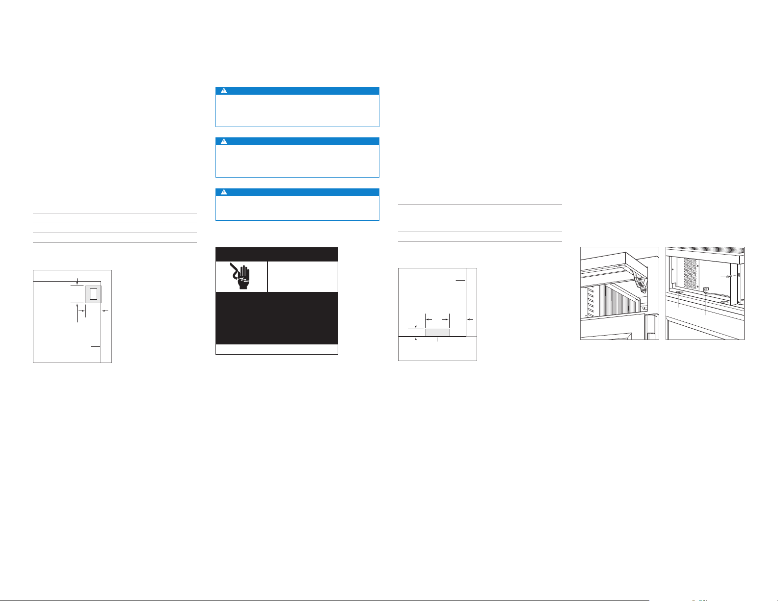
Product Information
Important product information, including the model and
serial number, are listed on the product rating plate. The
rating plate is located inside the cabinet, attached to the left
interior wall of the bottom drawer. Refer to the illustration
below.
If service is necessary, contact your authorized Sub-Zero
dealer.
RATING
PLATE
Rating plate location
Tools and Materials
• Screwdrivers—standard, Phillips, Torx, and hex.
• Power drill.
• Drill bits (masonry bits required for concrete installation).
• Standard Allen wrench set.
• Standard socket and wrench set.
• .6 m and 1.2 m levels.
• Tubing cutter.
• .9 m of 6.4 mm OD copper, braided stainless steel, or
PEX tubing.
• Saddle valve.
• Material to protect home, ooring, and cabinetry during
installation.
2 | English
Page 3
SITE PREPARATION
SIDE
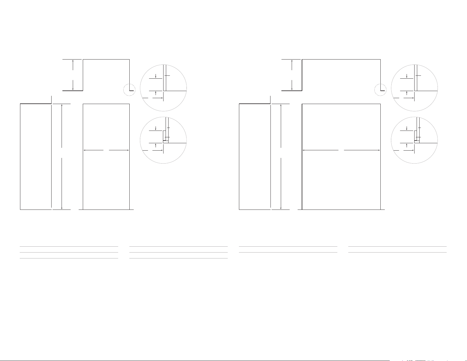
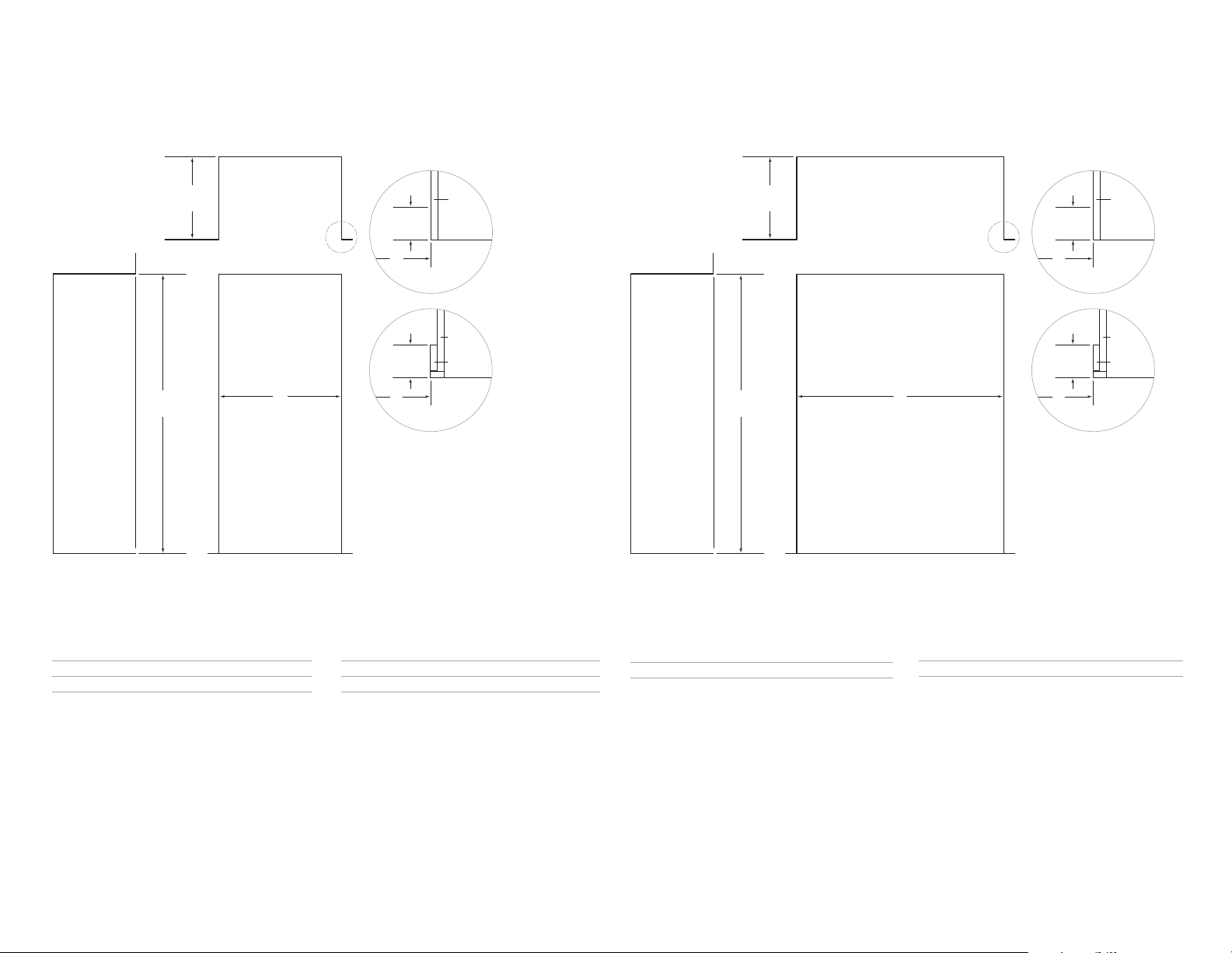
Opening Dimensions
STANDARD | FLUSH INSTALLATION
D
OPENING
DEPTH
TOP VIEW
H
OPENING
HEIGHT
NOTE: 89 mm finished returns will be visible and should be finished to match cabinetry.
W
OPENING WIDTH
FRONT VIEWSIDE VIEW
89 mm
FINISHED
RETURN
W
89 mm
FINISHED
RETURN
W
FRAMELESS
CABINETRY
FRAMED
CABINETRY
19 mm
TYPICAL
19 mm
TYPICAL
FILLER
Opening Dimensions
DUAL STANDARD | FLUSH INSTALLATION
D
OPENING
DEPTH
H
OPENING
HEIGHT
VIEW
NOTE: 89 mm finished returns will be visible and should be finished to match cabinetry.
TOP VIEW
W
OPENING WIDTH
FRONT VIEW
89 mm
FINISHED
RETURN
W
89 mm
FINISHED
RETURN
W
FRAMELESS
CABINETRY
FRAMED
CABINETRY
19 mm
TYPICAL
19 mm
TYPICAL
FILLER
STANDARD OPENING W
H D
914 mm Model 902 mm 2127 mm 610 mm
1219 mm Model 1206 mm 2127 mm 610 mm
For standard installations, the face frame will extend 51 mm
beyond cabinetry.
FLUSH OPENING
W H D
914 mm Model 914 mm 2137 mm 660 mm
1219 mm Model 1219 mm 2137 mm 660 mm
For ush installations, the face frame will be ush with surrounding cabinetry.
DUAL STANDARD OPENING W
H D
Two 914 mm Models 1816 mm 2127 mm 610 mm
A dual installation kit will be required for this installation.
DUAL FLUSH OPENING
W H D
Two 914 mm Models 1829 mm 2137 mm 660 mm
A dual installation kit will be required for this installation.
subzero.com | 3
Page 4
SITE PREPARATION
Electrical Requirements
Installation must comply with all applicable electrical codes
and be properly grounded (earthed).
International models from the factory designed without a
transformer require a 220-240 V AC, 50/60 Hz electrical
supply, fused at the correct rating for the unit. If required
by local or national codes, the power cord can be easily
replaced using the power inlet device.
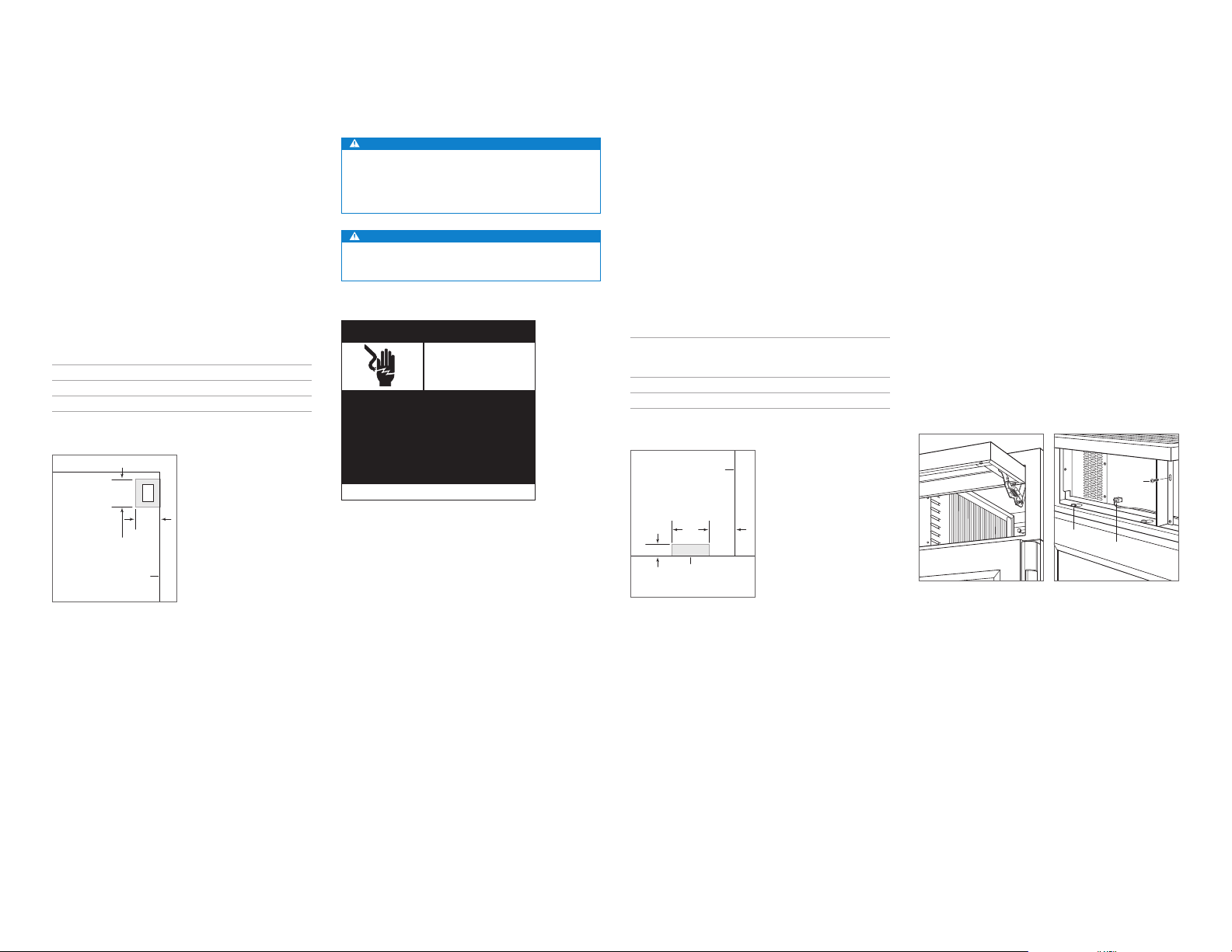
The electrical supply should be located within the shaded
area shown in the illustration below. A separate circuit servicing only this appliance is required. A ground fault circuit
interrupter (GFCI) is not recommended and may cause interruption of operation.
ELECTRICAL REQUIREMENTS
Electrical Supply 220-240 V AC, 50/60 Hz
Service 10 amp
Receptacle grounding-type (earthed)
178
E
mm
152
mm
1918 mm
FROM FLOOR
RIGHT SIDE
OF OPENING
Electrical supply location
CAUTION
The outlet must be checked by a qualied electrician
to be sure it is wired with the correct polarity. Verify the
outlet is properly grounded.
WARNING
Do not locate multiple portable socket-outlets, power
strip, or portable power supplies at the rear of the
appliance.
WARNING
Do not use an extension cord, two-prong adapter, or
remove the power cord ground prong.
Electrical
Shock
Hazard
Plug power cord directly into a properly
grounded (earthed) outlet.
Do not defeat the grounding (earthing)
nature of the plug.
Do not use adapter or extension cord.
Failure to follow these instructions could
cause serious injury or death.
See installation instructions
Plumbing Requirements
Installation must comply with all applicable plumbing codes.
The water supply line should be located within the shaded
area shown in the illustration below. The water supply line
should be connected to the house supply with an easily
accessible shut-off valve. Do not use self-piercing valves.
The water supply line must not interfere with installation of
the anti-tip bracket.
A reverse osmosis system can be used provided there
is constant water pressure of 2.4–8.3 bar supplied to the
unit at all times. A copper line is not recommended for this
application.
PLUMBING REQUIREMENTS
Water Supply 6.4 mm OD copper, braided
Pressure 2.4–8.3 bar (240–830 kPa)
Excess Line for Connection .9 m
RIGHT SIDE
OF OPENING
132
152
mm
mm
76 mm
AREA EXTENDS
Water supply location
13 mm
FORWARD ON FLOOR
stainless steel or PEX tubing
Preparation
Uncrate the unit, and inspect for damage. Remove the wood
base, and discard the shipping bolts and brackets. Remove
and recycle packing materials. Do not discard the kickplate,
anti-tip bracket, and hardware.
Completely retract the front leveling legs to allow the unit to
be moved into position. The front and rear leveling legs can
be adjusted from the front once the unit is in position.
Remove the drain pan from the base of the unit to avoid
damage and to allow for proper placement of the appliance
dolly.
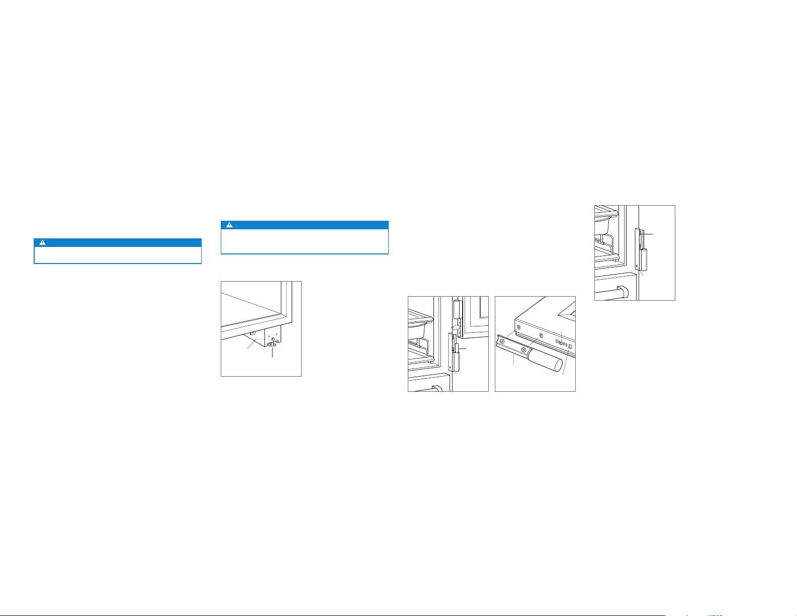
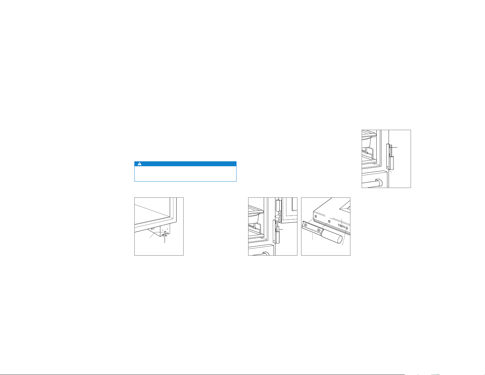
The grille assembly should be removed prior to moving
the unit. To remove, rotate the bottom of the grille upward.
Disconnect the network cable, then remove the center
mounting screw. Loosen the three grille bolts from the grille,
then pull the grille forward. Refer to the illustrations below.
SCREW
BOLT
CONNECTOR
Lift grille
Grille removal
4 | English
Page 5
INSTALLATION
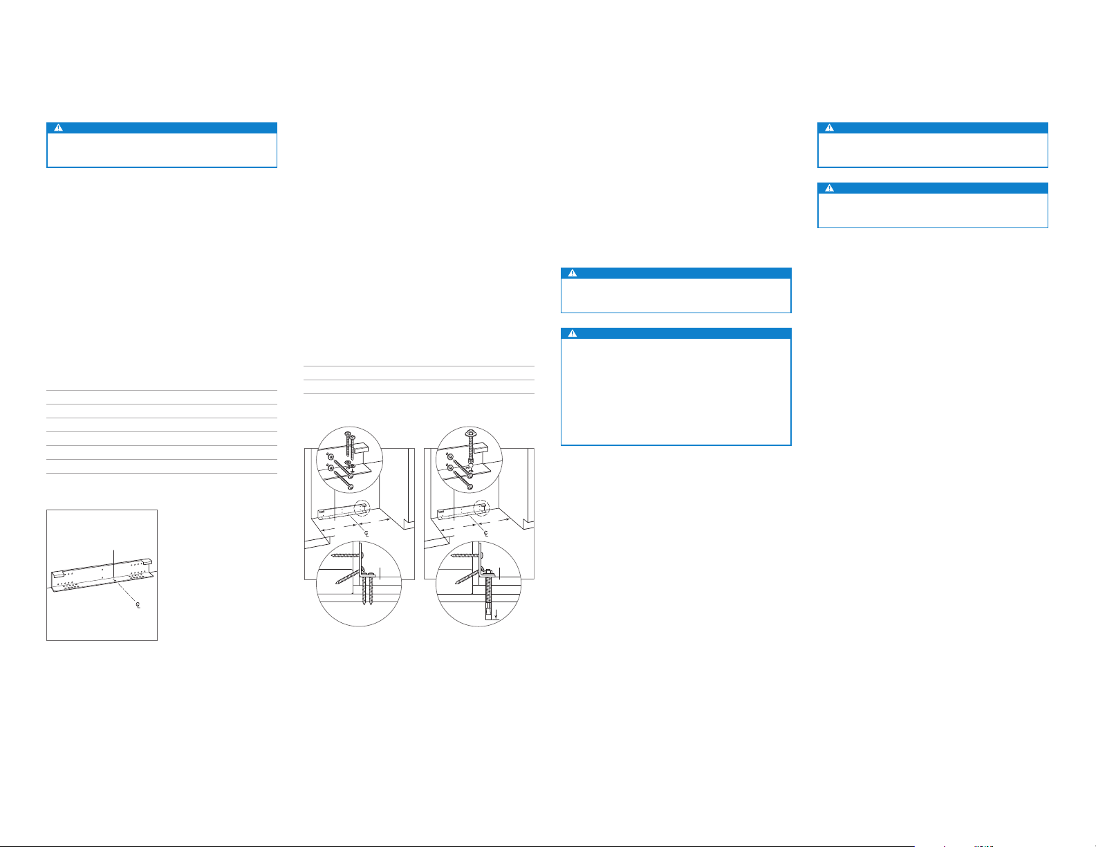
Anti-Tip Bracket
WARNING
To prevent the unit from tipping forward, the anti-tip
bracket must be installed.
Use the centerline locating holes to position the anti-tip
bracket in the center of the opening. The bracket must be
positioned 610 mm from the front of the opening to the back
of the bracket. This depth will increase to 660 mm for a ush
installation. Failure to properly position the anti-tip bracket
will prevent proper engagement.
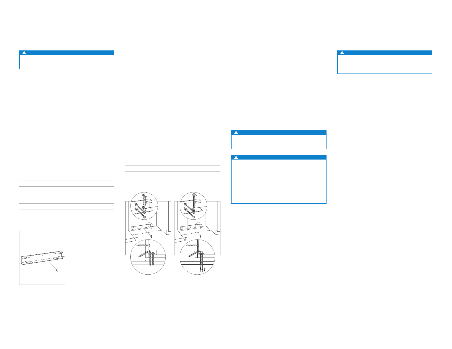
Use all anti-tip bracket hardware as instructed for wood or
concrete oors.
IMPORTANT NOTE: For wood or concrete oor applications,
if the #12 screws do not hit a wall stud or wall plate, use the
#8 screws and #12 washers with the wall anchors.
IMPORTANT NOTE: In some installations the subooring or
nished oor may necessitate angling the screws used to
fasten the anti-tip bracket to the back wall.
ANTI-TIP HARDWARE
1 Anti-tip bracket
12 #12 x 64 mm pan head screws
3
/8"–16 x 95 mm wedge anchors
3
12 #12 at washers
3 #8–18 x 32 mm truss head screws
3 Nylon Zip-it
®
wall anchors
WOOD FLOOR APPLICATION
After properly locating the anti-tip bracket in the opening,
drill pilot holes 5 mm diameter maximum in the wall studs
or wall plate. Use the #12 screws and washers to secure
the bracket. Verify the screws penetrate through the ooring
material and into wall studs or wall plate a minimum of 19
mm. Refer to the chart and illustration below.
CONCRETE FLOOR APPLICATION
After properly locating the anti-tip bracket in the opening,
drill pilot holes 5 mm diameter maximum in the wall studs
or wall plate. Drill 10 mm diameter holes into the concrete a
minimum of 38 mm deep. Use the #12 screws and washers
to secure the bracket to the wall, and use the
3
/8" wedge
anchors to secure the bracket to the oor. Verify the screws
penetrate wall studs or wall plate a minimum of 19 mm.
Refer to the chart and illustration below.
ANTI-TIP BRACKET PLACEMENT
914 mm Model 451 mm
1219 mm Model 603 mm
CONCRETE WEDGE ANCHOR INSTALLATION
1 Drill a 10 mm diameter hole any depth exceeding the
minimum embedment. Clean the hole or drill additional
depth to accommodate drill nes.
2 Assemble the washer and nut ush with the end of
anchor to protect threads. Drive the anchor through the
material to be fastened until the washer is ush with the
surface material.
3 Expand the anchor by tightening the nut 3–5 turns past
hand-tight position or to 34 newton-meters of torque.
WARNING
Verify there are no electrical wires or plumbing in the
area which the screws could penetrate.
CAUTION
Always wear safety glasses and use other neces-
A
sary protective devices or apparel when installing or
working with anchors.
Anchors are not recommended for use in lightweight
masonry material such as block or brick, or for use in
new concrete which has not had sufcient time to cure.
The use of core drills is not recommended to drill holes
for the anchors.
Placement
CAUTION
Before moving the unit into position, secure doors and
drawers closed, and protect any nished ooring.
WARNING
When positioning the appliance, ensure the supply
cord is not trapped or damaged.
Use an appliance dolly to move the unit near the opening.
If the unit has been on its back or side, it must stand upright
for a minimum of 24 hours before connecting power.
Plug the power cord into the grounded outlet, and roll the
unit into position. Verify the anti-tip bracket is properly
engaged.
CENTERLINE
LOCATING HOLES
Anti-tip bracket
A
A
FINISHED
FLOORING
WALL PLATE
SUBFLOORING
WOOD FLOOR
Wood oor
WALL PLATE
SUBFLOORING
Concrete oor
A
CONCRETE
FLOOR
A
FINISHED
FLOORING
38 mm
min
subzero.com | 5
Page 6
INSTALLATION
Water Line
Approximately .9 m of 6.4 mm plastic tubing is connected to
the unit with a preassembled
under the unit. The water line tting connection kit, provided
with the unit, contains a
connection to the household water line.
Purge the water line prior to nal connection to the unit. This
will remove any debris that may be present in the tubing
from installing the new water line.
Place the sleeve and nut on the water line and fasten
to the connection at the end of the tubing. Do not over
tighten. Check all water line ttings for leaks. Verify the
drain pan can be installed and removed without water line
interference.
IMPORTANT NOTE: Water lines can not be exposed to
freezing temperatures.
WARNING
Connect to potable water supply only.
1
/4" compression connection
1
/4" compression union tting for
Alignment
LEVELING
Once the unit is in position, turn the front leveling legs
clockwise to adjust the height. The rear height adjustment
can be made from the front of the roller base. Using a
socket, turn the
3
/8" hex bolt clockwise to raise the unit or
counterclockwise to lower. Use the lowest torque setting
when using a power drill. Do not turn the rear leveling legs
by hand. Refer to the illustration below.
When the unit is properly leveled, door and drawer adjustments are less likely to be necessary.
IMPORTANT NOTE: Level the unit to the oor, not the sur-
rounding cabinetry. This could affect the operation of the
unit, such as door closing.
WARNING
To reduce the possibility of the unit tipping forward, the
front leveling legs must be in contact with the oor.
REAR
ADJUSTMENT
Leveling.
FRONT
LEVELING LEG
3
/8"
DOOR ADJUSTMENT
The doors are adjustable in and out, up and down, and side
to side. In-and-out and up-and-down adjustments are made
on the door. Side-to-side adjustments are made on the
cabinet hinges. To make any adjustments, remove the door
and hinge pins. Refer to the illustration below.
In-and-Out and Up-and-Down Adjustment:
1 Place the door on a protected work surface, then loosen
the two upper hinge mounting screws.
2 Remove the two lower hinge mounting screws, then
remove the lower hinge.
3 Remove the positioning screw from the bottom of the
door, then use the adjustment pin to make up-and-down
and in-and-out adjustments. Refer to the illustration
below. Each vertical hole location adjusts the door
1 mm. The slotted holes allow for in-and-out adjustment.
4 Once the adjustments are made, install and tighten the
positioning screw.
POSITIONING
SCREW
HINGE
PIN
Door removal
DOOR HINGE
Door adjustment
ADJUSTMENT
PIN
Side-to-Side Adjustment:
1 Loosen the two mounting screws on the upper and/or
lower cabinet hinge. Refer to the illustration below.
2 Use the Allen wrench provided to rotate the adjustment
screw.
3 Verify the hinge is parallel to the side of the unit, then
tighten the mounting screws.
4 Install the hinge pins and door, then verify the door
alignment.
HINGE
SCREW
ADJUSTMENT
SCREW
Cabinet hinge adjustment
6 | English
Page 7

INSTALLATION
Alignment
DRAWER ADJUSTMENT
Up-and-Down Adjustment:
1 Use a hex wrench to turn the up-and-down adjustment
screw counterclockwise to raise and clockwise to lower.
Refer to the illustration below.
Side-to-Side Adjustment:
1 Use a hex wrench to turn the adjustment screw. Refer to
the illustration below.
2 Both drawer slides must be adjusted equally to achieve
movement. For example, if the right slide adjustment
screw rotated clockwise, rotate the left slide screw
equally counterclockwise.
Tilt Adjustment:
1 Loosen the side and the bottom, center screws. Refer to
the illustration below.
2 Remove the screw from the corner of the drawer that is
out of adjustment.
3 Move the drawer front in or out by hand.
4 Install the screw into the bottom of the drawer. Each hole
location adjusts the door in or out by 1 mm.
5 Tighten the side and bottom, center screws.
Anchoring
After the unit has been leveled and door and drawer adjustment completed, anchor the unit to the opening to ensure a
proper t and secure installation.
To Anchor the Unit:
1 Loosen the mounting bracket screws at the top of the
unit, then slide the mounting brackets to the side until
they contact the sides of the opening. Install additional
blocking if necessary. Refer to the illustration below.
2 Secure the brackets with the anchoring screws provided,
then tighten the mounting bracket screws.
ANCHORING
SCREWS
BRACKET SCREWS
Anchoring
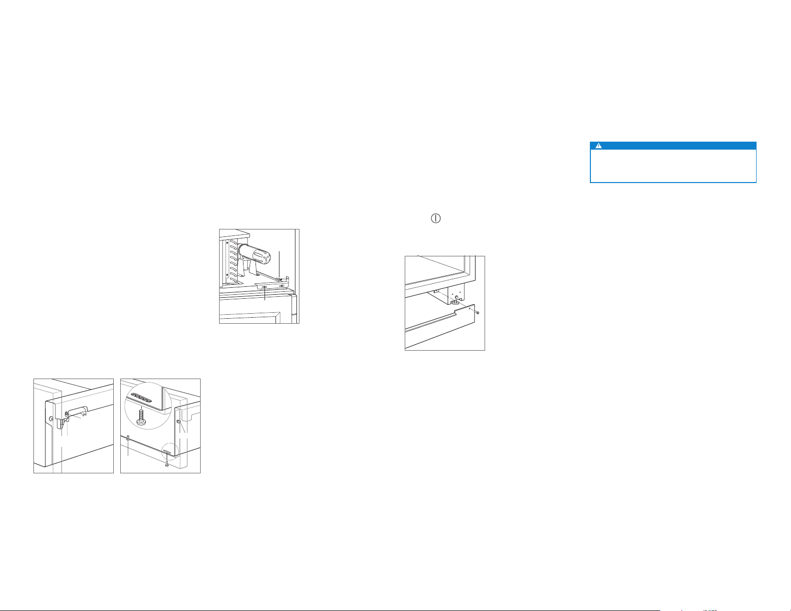
Completion
Install the grille assembly and check for proper t. Reconnect the network cable. Attach the network cable to the
grille using the cable ties provided.
Reinstall the drain pan and verify it is in the proper position.
Install the kickplate using the screws to attach it to the
brackets on the inside of each roller base. Refer to the illustration below. The kickplate must be removable for service.
The oor cannot interfere with removal.
Install the leg covers.
For initial start up, touch and hold
external touch display, located on the grille.
Kickplate installation
POWER on either
90° DOOR STOP
The door(s) of all models open to 135°. For installations
where the door opening must be limited, an optional 90°
door stop kit is available through an authorized Sub-Zero
dealer.
WARNING
Follow all local laws when storing, recycling, or discarding unused refrigerators and freezers.
SIDE-TO-SIDE
ADJUSTMENT
UP-AND-DOWN
ADJUSTMENT
LOOSEN
Drawer adjustment
Sub-Zero, Sub-Zero & Design, Sub-Zero & Snowake Design, Dual Refrigeration, The Living Kitchen, Great American Kitchens, The Fine Art of Kitchen Design, Wolf, Wolf & Design, Wolf Gourmet, W & Design, red colored knobs, Cove, and Cove & Design are registered trademarks and service marks of Sub-Zero Group, Inc. and its subsidiaries.
All other trademarks are property of their respective owners in the United States and other countries.
Drawer tilt adjustment
LOOSEN
subzero.com | 7
Page 8

REFRIGERACIÓN PRO
Índice
2 Refrigeración PRO
3 Medidas de la cavidad
4 Instalación eléctrica
4 Fontanería
4 Preparación
5 Soporte antivuelco
5 Colocación
6 Conducto de agua
6 Alineación
7 Anclaje
7 Finalización
Nota importante:
Para garantizar que este producto se instala y funciona de
la forma más ecaz y segura posible, tenga en cuenta la
información que se destaca en esta guía:
Cuando aparece
que resulta especialmente importante.
PRECAUCIÓN indica una situación en la que se pueden
sufrir heridas leves o provocar daños al producto si no se
siguen las instrucciones.
AVISO indica el peligro de que se produzcan heridas graves
o incluso la muerte si no se respetan las precauciones.
NOTA IMPORTANTE, se resalta información
Información del producto
En la placa de datos del producto encontrará información
importante, incluyendo el modelo y el número de serie. La
placa de datos está situada en el interior del armario, jada
en la pared inferior izquierda del cajón inferior. Observe la
siguiente ilustración.
Si necesita recurrir a un servicio técnico, póngase en
contacto con su distribuidor de Sub-Zero autorizado.
PLACA DE
DATOS
Ubicación de la placa de datos
Herramientas y materiales
• Destornilladores: estándar, Phillips, Torx y hexagonales.
• Taladro.
• Brocas (se necesitarán brocas de mampostería para la
instalación en hormigón).
• Juego de llaves Allen estándar.
• Juego de llaves y llaves de vaso estándar.
• Niveles de 0,6 m y 1,2 m.
• Instrumento especial para cortar el tubo.
• Tubo de 0,9 m de 6,4mm de cobre OD, acero inoxidable
trenzado o de PEX.
• Válvula de montaje.
• Material para proteger la casa, el suelo y los armarios de
cocina durante la instalación.
2 | Español
Page 9
PREPARACIÓN DEL SITIO
VIST
Medidas de la cavidad
INSTALACIÓN EMPOTRABLE | ESTÁNDAR
D
PROFUNDIDAD
DE LA CAVIDAD
VISTA SUPERIOR
H
ALTURA DE
LA CAVIDAD
NOTA: los retornos acabados de 89 mm serán visibles y deberán acabarse para que coincidan con los muebles.
W
ANCHURA DE LA CAVIDAD
VISTA FRONTALVISTA LATERAL
RETORNO
ACABADO
89 mm
DE
W
MOBILIARIO
SIN MARCO
RETORNO
ACABADO
89 mm
DE
W
MOBILIARIO
CON MARCO
19 mm
ESTÁNDAR
19 mm
ESTÁNDAR
RELLENO
Medidas de la cavidad
INSTALACIÓN EMPOTRABLE | DOBLE ESTÁNDAR
D
PROFUNDIDAD
DE LA CAVIDAD
VISTA SUPERIOR
H
ALTURA DE
LA CAVIDAD
A LATERAL
NOTA: los retornos acabados de 89 mm serán visibles y deberán acabarse para que coincidan con los muebles.
W
ANCHURA DE LA CAVIDAD
VISTA FRONTAL
RETORNO
ACABADO
89 mm
DE
W
MOBILIARIO
SIN MARCO
RETORNO
ACABADO
89 mm
DE
W
MOBILIARIO
CON MARCO
19 mm
ESTÁNDAR
19 mm
ESTÁNDAR
RELLENO
CAVIDAD
ESTÁNDAR
W H D
Modelo de 914 mm 902 mm 2127 mm 610 mm
Modelo de 1219 mm 1206 mm 2127 mm 610 mm
En el caso de las instalaciones estándar, el marco frontal se
prolonga 51 mm por detrás del mueble.
CAVIDAD
EMPOTRABLE
W H D
Modelo de 914 mm 914 mm 2137 mm 660 mm
Modelo de 1219 mm 1219 mm 2137 mm 660 mm
En instalaciones empotrables, el marco frontal se nivela con
el mobiliario circundante.
CAVIDAD DOBLE
ESTÁNDAR
. W H D
Dos modelos de 914 mm 1816 mm 2127 mm 610 mm
Para esta instalación se necesita un kit de instalación doble.
CAVIDAD DOBLE
EMPOTRABLE
W H D
Dos modelos de 914 mm 1829 mm 2137 mm 660 mm
Para esta instalación se necesita un kit de instalación doble.
subzero.com | 3
Page 10
PREPARACIÓN DEL SITIO
13 mm
CIA DELANTE EN EL SUELO
Requisitos eléctricos
La instalación debe cumplir con todas las normativas
eléctricas aplicables y debe estar correctamente conectada
a tierra.
Los modelos internacionales diseñados de fábrica sin
transformador precisan un suministro eléctrico de
220-240V CA, 50/60 Hz, con fusible para el voltaje correcto
de la unidad. Si la normativa local o nacional lo exige, el
cable eléctrico se puede sustituir con facilidad
con el dispositivo de entrada de alimentación.
La toma eléctrica debe situarse en el área sombreada en la
siguiente ilustración. Se necesita un circuito independiente
para esta unidad. No se recomienda utilizar un interruptor
de circuito de fallos de toma de tierra (GFCI), ya que puede
interrumpir el funcionamiento de la unidad.
REQUISITOS ELÉCTRICOS
Suministro eléctrico 220-240 V CA, 50/60 Hz
Servicio 10 amperios
Enchufe con toma de tierra
178
E
mm
152
mm
1918 mm
DESDE EL SUELO
LADO DERECHO
DE LA CAVIDAD
Ubicación de la alimentación
eléctrica
PRECAUCIÓN
La toma de corriente debe ser revisada por un electricista
cualicado para comprobar la conexión se ha realizado
con la polaridad correcta. Compruebe que la toma de
corriente está conectada a tierra de manera correcta.
AVISO
No utilice alargadores ni adaptadores, ni quite la clavija
de toma a tierra del cable eléctrico.
Potencia
Descarga
eléctrica
Enchufe el cable eléctrico directamente en
una toma con conexión a tierra.
No manipule la conexión a tierra del
enchufe.
No utilice adaptadores ni alargadores.
Si no sigue estas instrucciones, existe
riesgo de que se produzcan heridas graves
o incluso la muerte.
Ver instrucciones de instalación
Requisitos de fontanería
La instalación debe cumplir con toda la normativa local
aplicable en materia de fontanería.
La toma de agua puede situarse en el área sombreada
de la siguiente ilustración. El conducto de abastecimiento
de agua se debe conectar al suministro de la casa con
una válvula de cierre de fácil acceso. No utilice válvulas
autoperforantes. El conducto del agua no debe interferir en
la instalación del soporte antivuelco.
Es posible utilizar un sistema de ósmosis invertido, siempre
y cuando la presión de agua que llegue a la unidad se
mantenga de forma constante entre 2,4 y 8,3 bares. No se
recomienda utilizar tubos de cobre para esta aplicación.
REQUISITOS DE FONTANERÍA
Suministro de agua Tubo de 6,4 mm de cobre OD,
Presión 2,4–8,3 bares
Conducto sobrante para conexión 0,9 m
LADO DERECHO
DE LA CAVIDAD
132
152
mm
mm
76 mm
EL ÁREA SE EXTIENDE
HA
Ubicación de la toma de agua
acero inoxidable trenzado o
de PEX
Preparación
Desembale la unidad y compruebe si tiene algún daño o
desperfecto. Retire la base de madera y extraiga todos
los tornillos y soportes del paquete. Quite y recicle los
materiales de embalaje. No tire el zócalo, el soporte
antivuelco ni las piezas de montaje.
Repliegue completamente las patas de nivelación
delanteras para permitir que la unidad se pueda colocar en
la posición adecuada. Las patas de nivelación delanteras y
traseras pueden ajustarse desde la parte delantera cuando
la unidad ya esté colocada.
Retire el depósito de desagüe de la base de la unidad para
evitar que se dañe y para que se pueda colocar bien la
plataforma rodante.
Retire la rejilla antes de mover la unidad. Para retirarla, gire
la parte inferior de la rejilla hacia arriba. Desconecte el cable
de red, y luego retire el tornillo de montaje central. Aoje los
tres pernos de la rejilla y luego tire de la rejilla hacia delante.
Observe las siguientes ilustraciones.
TORNILLO
PERNO
CONECTOR
Levante la rejilla
Extracción de la rejilla
4 | Español
Page 11
INSTALACIÓN
Soporte antivuelco
AVISO
Debe instalarse el soporte antivuelco para evitar que la
unidad se incline hacia adelante.
Utilice los oricios para jación en la línea central para
colocar el soporte antivuelco en el centro de la cavidad.
El soporte debe colocarse a 610 mm desde la parte
delantera de la cavidad a la parte trasera del soporte. Esta
profundidad se incrementará hasta 660 mm si se trata de
una instalación empotrable. Si no coloca bien el soporte
antivuelco, es posible que no quede bien jado.
Utilice todas las piezas del soporte antivuelco tal y como se
indica en las instrucciones para suelos de madera o
de hormigón.
NOTA IMPORTANTE: para aplicaciones en suelos de madera
o de hormigón, en caso de que los tornillos del n.º 12 no
alcancen el montante o la placa de pared, utilice tornillos
del n.º 8 y arandelas del n.º 12 con los anclajes para pared.
NOTA IMPORTANTE: en algunas instalaciones es posible
que, debido al tipo de suelo o acabado de este, sea
necesario colocar inclinados los tornillos utilizados para
sujetar los soportes antivuelco a la pared trasera.
PIEZAS ANTIVUELCO
1 Soporte antivuelco
12 Tornillos de cabeza plana del n.º 12 (64 mm)
3 Anclajes de expansión de 16 x 95 mm –
12 Arandelas planas del n.º 12
3 Tornillos de cabeza ovalada del n° 8 (18 x 32 mm)
3 Anclajes para pared de nailon Zip-it
3
/8"
®
APLICACIÓN EN SUELO DE MADERA
Tras colocar correctamente el soporte antivuelco en la
cavidad, perfore oricios guía de 5mm de diámetro como
máximo en los montantes de pared o en la placa de pared.
Utilice arandelas y tornillos del n.º 12 para jar el soporte.
Compruebe que los tornillos penetren en el material del
suelo y en los montantes de pared o en las placas un
mínimo de 19 mm. Consulte la tabla e ilustración siguientes.
APLICACIÓN EN SUELO DE HORMIGÓN
Tras colocar correctamente el soporte antivuelco en la
cavidad, perfore oricios guía de 5mm de diámetro como
máximo en los montantes de pared o en la placa de pared.
Realice oricios de 10 mm de diámetro en el hormigón con
una profundidad mínima de 38 mm. Utilice arandelas y
tornillos del n.º 12 para jar el soporte a la pared, y anclajes
de expansión de
3
/8" (9,5 mm) para jar los soportes al suelo.
Compruebe que los tornillos penetren en los montantes de
pared o en las placas un mínimo de 19 mm. Consulte la tabla
y la ilustración que se incluyen a continuación.
COLOCACIÓN DEL SOPORTE ANTIVUELCO A
Modelo de 914 mm 451 mm
Modelo de 1219 mm 603 mm
INSTALACIÓN DE ANCLAJES DE EXPANSIÓN PARA
HORMIGÓN
1 Haga un agujero de 10 mm de diámetro con una
profundidad superior al incrustado mínimo. Limpie el
oricio o continúe taladrando para hacer que el oricio
sea más profundo y quepan en él los residuos.
2 Coloque la arandela y la tuerca al nivel del extremo del
anclaje para proteger las roscas. Inserte el anclaje en el
material en el que debe atornillarse hasta que la arandela
quede nivelada con el material de la supercie.
3 Extienda el anclaje mediante una llave que sirva para
apretar la tuerca de 3 a 5 vueltas más de su posición
lograda con el apriete manual o hasta 34 Newton metros
de par.
AVISO
Compruebe que no haya cables eléctricos ni tuberías
en el área en la que se van a introducir los tornillos.
PRECAUCIÓN
Lleve siempre gafas de seguridad y utilice cualquier
otro dispositivo o ropa de protección que sea necesario
cuando esté instalando o trabajando con anclajes.
Se recomienda no utilizar los anclajes en material de
mampostería poco pesado, por ejemplo, bloques o
ladrillos, ni utilizarlo en hormigón fresco que no se haya
secado el tiempo suciente. No se recomienda utilizar
brocas huecas para hacer oricios para los anclajes.
Colocación
PRECAUCIÓN
Antes de desplazar la unidad para colocarla en su sitio,
asegúrese de que las puertas y cajones estén cerrados
y proteja el acabado del suelo.
Utilice una plataforma rodante para desplazar la unidad
hasta la cavidad.
Si la unidad ha estado boca abajo o sobre uno de los
lados, debe permanecer en posición vertical como mínimo
24horas antes de conectarla a la alimentación.
Enchufe el cable eléctrico en la toma de conexión a tierra y
coloque la unidad en la posición adecuada. Compruebe que
el soporte antivuelco esté bien jado.
ORIFICIOS PARA FIJACIÓN
EN LA LÍNEA CENTRAL
Soporte antivuelco
A
A
SUELO
TERMINADO
PLACA DE PARED
CONTRAPISO
SUELO DE MADERA
Suelo de madera
PLACA DE PARED
TIPO DE SUELO
Suelo de hormigón
A
SUELO DE
HORMIGÓN
A
SUELO
ACABADO
38 mm
min.
subzero.com | 5
Page 12
INSTALACIÓN
Conducto de agua
Debe conectar un tubo de plástico de aproximadamente
0,9 m de 6,4 mm a la unidad con una conexión de presión
1
/4" montada debajo de la unidad. El equipo de conexión
de
para instalar la toma de agua, suministrado con la unidad,
incluye un ajuste de la unión de compresión de
conectarlo a la toma de agua doméstica.
Purgue el conducto de agua antes de conectarlo a la unidad.
Esto hará que se elimine cualquier tipo de suciedad que
pueda haber en el tubo al instalar el nuevo conducto de agua.
Coloque la tuerca y el manguito en el conducto del agua y
sujételo a la conexión del extremo del tubo. No lo apriete
demasiado. Compruebe si existe alguna fuga de agua en
las conexiones del conducto. Compruebe que el depósito
de desagüe puede instalarse y desmontarse sin que se
produzca ningún problema en la toma de agua.
NOTA IMPORTANTE: no se pueden exponer las tomas de
agua a temperaturas de congelación.
1
/4" para
Alineación
NIVELADO
Una vez que la unidad esté colocada en su sitio, gire las
patas de nivelación delanteras en el sentido de las agujas
del reloj para ajustar la altura. El ajuste de la altura de la
parte trasera se puede realizar desde la parte delantera de
la base de la rueda. Con ayuda de una llave de vaso de
gire el tornillo hexagonal de
3
/8" en el sentido de las agujas
del reloj para levantar la unidad y en sentido contrario para
bajarla. Utilice el ajuste de torsión más pequeño si utiliza
un taladro. No gire manualmente las patas de nivelación
trasera. Observe la siguiente ilustración.
Cuando la unidad esté correctamente nivelada, no será
tan necesario realizar los ajustes de las puertas y de los
cajones.
NOTA IMPORTANTE: nivele la unidad con el suelo, y no con
los demás muebles. Esto puede afectar al funcionamiento
de la unidad, por ejemplo, es posible que la puerta no se
cierre correctamente.
AVISO
Para evitar que la unidad vuelque hacia delante, las patas
de nivelación delanteras deben llegar hasta el suelo.
AJUSTE
TRASERO
PATA DE NIVELACIÓN
DELANTERA
Nivelado
3
AJUSTE DE LA PUERTA
Las puertas pueden ajustarse hacia dentro y hacia fuera,
de arriba a abajo y de lado a lado. Los ajustes hacia dentro
y hacia fuera y de arriba a abajo se efectúan en la puerta,
mientras que los de laterales se realizan en las bisagras del
/8",
armario. Para realizar cualquier ajuste, extraiga la puerta y
las clavijas de las bisagras. Observe la siguiente ilustración.
Ajuste hacia dentro y hacia fuera y de arriba a abajo:
1 Coloque la puerta sobre una supercie de trabajo
protegida, y luego aoje los tornillos de montaje de la
bisagra superior.
2 Extraiga los dos tornillos de montaje de la bisagra
inferior y luego retire la propia bisagra inferior.
3 retire el tornillo de posicionamiento de la parte inferior de
la puerta, y luego utilice la clavija de ajuste para efectuar
los ajustes hacia dentro y hacia afuera o de arriba a
abajo. Observe la siguiente ilustración. La ubicación de
cada oricio vertical ajusta la puerta 1mm. Los oricios
ranurados permiten ajustar la puerta de arriba a abajo.
4 Cuando haya terminado de realizar los ajustes, vuelva a
colocar el tornillo de posicionamiento y apriételo.
PASADOR
DE LA
BISAGRA
BISAGRA DE
LA PUERTA
Extracción de la puerta
Ajuste de la puerta
TORNILLO DE
POSICIONAMIENTO
PASADOR
DE AJUSTE
Ajuste de lado a lado:
1 Aoje los dos tornillos de montaje de la bisagra superior
o inferior del armario (o ambas). Observe la siguiente
ilustración.
2 Utilice la llave Allen suministrada para girar el tornillo
de ajuste.
3 Compruebe que la bisagra está paralela al lateral de la
unidad, y luego apriete los tornillos de montaje.
4 Instale las clavijas de la bisagra y la puerta, y por último
compruebe la alineación de la puerta.
TORNILLO
DE LA
BISAGRA
TORNILLO
DE AJUSTE
Ajuste de la bisagra del armario
6 | Español
Page 13
INSTALACIÓN
Alineación
AJUSTE DEL CAJÓN
Ajuste hacia arriba y hacia abajo:
1 Utilice una llave hexagonal para girar el tornillo de ajuste
hacia arriba y hacia abajo hacia la derecha para subirlo
y hacia la izquierda para bajarlo. Observe la siguiente
ilustración.
Ajuste de lado a lado:
1 Utilice una llave hexagonal para girar el tornillo de ajuste.
Observe la siguiente ilustración.
2 Los dos deslizadores del cajón deben estar igualmente
ajustados para permitir su movimiento. Por ejemplo, si
el tornillo de ajuste de deslizamiento derecho se giró
hacia la izquierda, gire del mismo modo el tornillo de
deslizamiento izquierdo hacia la derecha.
Ajuste de la inclinación:
1 Aoje los tornillos de la parte central, inferior y lateral.
Observe la siguiente ilustración.
2 Retire el tornillo de la esquina del cajón que necesita
ajustarse.
3 Mueva la parte delantera del cajón hacia dentro o hacia
fuera con la mano.
4 Coloque el tornillo en la parte inferior del cajón. La
ubicación de cada oricio ajusta la puerta hacia dentro o
hacia fuera 1 mm.
5 Apriete los tornillos de la parte central, inferior y lateral.
Anclaje
Cuando la unidad esté nivelada y se haya ajustado el cajón,
ancle la unidad a la cavidad para garantizar que se ajusta
correctamente y que la instalación es segura.
Para anclar la unidad:
1 Aoje los tornillos del soporte de montaje de la parte
superior de la unidad y luego deslice los soportes de
montaje hacia el lado hasta que toquen los lados de
la cavidad. Coloque bloqueos adicionales en caso
necesario. Observe la siguiente ilustración.
2 Fije los soportes con los tornillos de anclaje
suministrados, y luego apriete los tornillos de los
soportes de montaje.
TORNILLOS
DE ANCLAJE
TORNILLOS PARA
EL SOPORTE
Anclaje
Finalización
Instale el conjunto de la rejilla y compruebe que se ajusta
correctamente. Vuelva a conectar el cable de red. Fije el
cable de red a la rejilla utilizando las conexiones de cable
suministradas.
Vuelva a instalar el depósito de desagüe y compruebe que
está en el lugar adecuado.
Instale el zócalo con tornillos para jarlo a los soportes
del interior de la base de cada rueda. Observe la siguiente
ilustración. El zócalo debe ser extraíble para permitir sacarlo
en caso de avería. El suelo no puede ser un impedimento
para llevar a cabo esta operación.
Instale las cubiertas de las patas.
Para el encendido inicial, mantenga pulsar el botón de
POWER
externas, situadas en la rejilla.
Instalación del zócalo
(encendido) en una de las pantallas táctiles
TOPE DE PUERTA A 90°
Las puertas de todos los modelos se abren a 135º. Para
instalaciones donde la apertura de la puerta debe limitarse,
podrá encontrar un kit de tope de puerta de 90º opcional a
través de un distribuidor de Sub-Zero autorizado.
AVISO
Cumpla con todas las normativas locales para el
almacenamiento, reciclaje o eliminación de frigorícos
y congeladores que no se utilicen.
AJUSTE DE
LADO A LADO
AJUSTE HACIA ARRIBA
Y HACIA ABAJO
AFLOJAR
Ajuste del cajón
Sub-Zero, Sub-Zero & Design, Sub-Zero & Snowake Design, Dual Refrigeration, The Living Kitchen Great American Kitchens The Fine Art of Kitchen Design, Wolf, Wolf & Design, Wolf Gourmet, W & Design, los mandos de color rojo, Cove, y Cove & Design son marcas registradas y marcas de servicio de Sub-Zero Group, Inc. y sus liales.
Todas las demás marcas son propiedad de sus respectivos propietarios en los Estados Unidos y en otros países.
Ajuste de la inclinación del cajón
AFLOJAR
subzero.com | 7
Page 14

RÉFRIGÉRATEUR PRO
Table des matières
2 Réfrigérateur PRO
3 Cotes d’encastrement
4 Électricité
4 Plomberie
4 Préparation
5 Support antibasculement
5 Emplacement
6 Canalisation d’eau
6 Alignement
7 Ancrage
7 Dernières nitions
Remarque importante
Pour garantir une installation de ce produit aussi sûre
et efcace que possible, veuillez faire particulièrement
attention aux mentions mises en évidence tout au long de
ce guide, notamment :
REMARQUE IMPORTANTE met l’accent sur un
renseignement particulièrement important.
MISE EN GARDE signale un danger qui pourrait causer une
blessure mineure ou endommager le produit si vous ne
suivez pas les instructions.
AVERTISSEMENT signale un danger qui pourrait causer
des blessures graves voire fatales si vous ne prenez pas
certaines précautions.
Information concernant le produit
Les renseignements importants concernant le produit,
notamment la référence modèle et le numéro de série,
gurent sur la plaque des caractéristiques du produit. La
plaque des caractéristiques du produit se trouve dans
l’élément, xée à la paroi gauche intérieure du tiroir inférieur.
Reportez-vous à l’illustration ci-après.
S’il faut effectuer une réparation, adressez-vous à un
revendeur Sub-Zero agréé.
PLAQUE
SIGNALÉTIQUE
Emplacement de la plaque
des caractéristiques
Outils et matériaux
• Tournevis—normaux, Phillips, Torx et hexagonaux.
• Perceuse électrique.
• Mèches (mèches de maçonnerie nécessaires pour
l’installation dans le béton).
• Jeu de clés Allen normales.
• Jeu de clés et de douilles normales.
• Niveaux de 0,6 m et 1,2 m.
• Coupe-tube.
• Tube PEX, en acier inoxydable tressé ou en cuivre de
0,9m de long et de 6,4 mm de diamètre extérieur.
• Robinet-vanne.
• Matériel pour protéger la maison, le sol et le mobilier
pendant l’installation.
2 | Français
Page 15

PRÉPARATION DE L’EMPLACEMENT
VUE LA
Cotes d’encastrement
INSTALLATION CLASSIQUE | ENCASTRÉE
D
PROFONDEUR
D’OUVERTURE
VUE EN PLAN
H
HAUTEUR
D’OUVERTURE
REMARQUE : Les replis finis de 89 mm sont visibles et doivent être finis pour être assortis aux autres éléments de cuisine.
W
LARGEUR D’OUVERTURE
VUE DE FACEVUE LATÉRALE
REPLI FINI
W
REPLI FINI
W
89 mm
MEUBLES SANS
MOULURE
89 mm
MEUBLES
AVEC CADRE
19 mm
EN GÉNÉRAL
19 mm
EN GÉNÉRAL
FILLER
Cotes d’encastrement
INSTALLATION CLASSIQUE | ENCASTRÉE
CONJOINTE
D
PROFONDEUR
D’OUVERTURE
VUE EN PLAN
H
HAUTEUR
D’OUVERTURE
TÉRALE
REMARQUE : Les replis finis de 89 mm sont visibles et doivent être finis pour être assortis aux autres éléments de cuisine.
W
LARGEUR D’OUVERTURE
VUE DE FACE
REPLI FINI
89 mm
W
MEUBLES SANS
MOULURE
REPLI FINI
89 mm
W
MEUBLES
AVEC CADRE
19 mm
EN GÉNÉRAL
19 mm
EN GÉNÉRAL
FILLER
OUVERTURE
CLASSIQUE
W H D
Modèle de 914 mm 902 mm 2127 mm 610 mm
Modèle de 1219 mm 1206 mm 2127 mm 610 mm
Lors d’une installation classique, le cadre de la façade
dépasse du meuble de 51 mm.
OUVERTURE
ENCASTRÉE
W H D
Modèle de 914 mm 914 mm 2137 mm 660 mm
Modèle de 1219 mm 1219 mm 2137 mm 660 mm
Lors d’une installation encastrée, le cadre de la façade est à
eur des meubles adjacents.
OUVERTURE CLASSIQUE
CONJOINTE
W H D
Deux modèles de 914 mm 1816 mm 2127 mm 610 mm
Il sera nécessaire d’avoir un kit d’installation conjointe pour
cette installation.
OUVERTURE ENCASTRÉE
CONJOINTE
W H D
Deux modèles de 914 mm 1829 mm 2137 mm 660 mm
Il sera nécessaire d’avoir un kit d’installation conjointe pour
cette installation.
subzero.com | 3
Page 16

PRÉPARATION DE L’EMPLACEMENT
Conguration électrique
L’installation doit se conformer à tous les codes électriques
applicables. Elle doit être correctement mise à la terre.
Les modèles internationaux issus de l’usine conçus sans
transformateur requièrent une alimentation électrique de
220-240 V c. a., 50/60 Hz, dotée de fusibles ayant les
caractéristiques nominales appropriées à l’appareil. Le
cordon électrique peut facilement être remplacé à l’aide
d’un dispositif d’arrivée du courant si les codes locaux ou
nationaux l’exigent.
L’alimentation en électricité doit se trouver dans la zone
ombrée indiquée sur l’illustration ci-dessous. Il est nécessaire
d’avoir un circuit indépendant, alimentant uniquement cet
appareil ménager. Il n’est pas recommandé d’avoir recours
à un disjoncteur différentiel (GFCI) qui pourrait provoquer
l’interruption du fonctionnement de l’appareil.
CONFIGURATION ÉLECTRIQUE
Alimentation électrique 220-240 V c.a., 50/60 Hz
Service 10 A
Prise mise à la terre
178
E
mm
152
mm
1918 mm
À PARTIR DU SOL
CÔTÉ DROIT
DE L’OUVERTURE
Emplacement de l’alimentation
électrique
MISE EN GARDE
La prise doit être vériée par un électricien qualié.
Celui-ci doit s’assurer qu’elle est dotée de la polarité
adéquate. Assurez-vous que la prise est correctement
mise à la terre.
AVERTISSEMENT
N’utilisez pas de rallonge ni d’adaptateur à deux
broches. Ne retirez pas non plus la broche de mise à la
terre du cordon électrique.
Électricité
Danger de
choc électrique
Branchez directement le cordon électrique
dans une prise avec mise à la terre
adéquate.
N’entravez pas la fonction de mise à la
terre de la prise.
N’utilisez pas d’adaptateur ou de cordon
de rallonge.
Le non-respect de ces instructions pourrait
entraîner des blessures graves voire
mortelles.
Voir les instructions d’installation
Conguration de la plomberie
L’installation doit se conformer à tous les codes de
plomberie applicables.
L’arrivée d’eau doit se trouver dans la zone ombrée indiquée
sur l’illustration ci-après. La lyre devra être branchée à
l’alimentation en eau de la maison avec un robinet d’arrêt
facile d’accès. N’utilisez pas de robinet auto-perceur. La
canalisation d’eau ne doit pas gêner l’installation du support
antibasculement.
Un système d’osmose inversé peut être utilisé, à condition
qu’une pression d’eau constante de 2,4 à 8,3 bars alimente
en permanence l’appareil. Il n’est pas conseillé d’avoir
recours à une conduite en cuivre pour cette application.
CONFIGURATION DE LA PLOMBERIE
Alimentation en eau Tube PEX, en acier inoxydable
Pression 2,4–8,3 bars
Surplus de la canalisation d’eau
pour le branchement
CÔTÉ DROIT
DE L’OUVERTURE
132
152
mm
mm
76 mm
CETTE ZONE SE PROLONGE
13 mm VERS L’ AVANT AU SOL
DE
Emplacement de l’arrivée d’eau
tressé ou en cuivre de 6,4 mm
de diamètre extérieur
0,9 m
Préparation
Dégagez l’appareil du carton et inspectez-le an de déceler
tout dommage éventuel. Retirez le socle en bois et jetez les
boulons et les supports d’expédition. Retirez et recyclez les
matériaux d’emballage. Ne jetez pas la plinthe, le support
antibasculement ni le matériel de xation.
Rentrez complètement les pieds de mise à niveau le temps
de mettre l’appareil à l’endroit prévu. Les pieds de mise à
niveau avant et arrière seront ajustés depuis l’avant une fois
que l’appareil sera en place.
Retirez le bac de vidange de la base de l’appareil pour éviter
de l’endommager et faciliter le maniement du diable spécial
appareils ménagers.
Il est conseillé de retirer la grille avant de déplacer l’appareil.
Pour y accéder, redressez la partie inférieure de la grille
vers le haut. Débranchez le câble de réseau, puis retirez
la vis de montage centrale. Desserrez les trois boulons de
la grille, puis tirez la grille vers l’avant. Reportez-vous aux
illustrations ci-après.
VIS
BOULON
RACCORD
Soulevez la grille
Retrait de la grille
4 | Français
Page 17

INSTALLATION
Support antibasculement
AVERTISSEMENT
Les supports antibasculement doivent être installés
pour empêcher l’appareil de basculer vers l’avant.
Utilisez les trous permettant d’identier l’axe pour placer
le support antibasculement au centre de l’ouverture. Le
support doit être placé à 610 mm de l’avant de l’ouverture
à l’arrière du support. La distance en profondeur sera
de 660 mm pour une installation intégrée. Si le support
antibasculement n’est pas correctement positionné,
vous ne pourrez pas bien engager l’appareil.
Utilisez tous les accessoires de xation pour les supports
antibasculement conformément aux directives pour les
planchers en bois ou les sols en béton.
REMARQUE IMPORTANTE : Dans le cas de planchers en
bois ou en béton, si les vis n° 12 ne rencontrent pas de
montant mural ni de plaque murale, utilisez les vis n° 8
et les rondelles n° 12 avec les pièces d’ancrage mural.
REMARQUE IMPORTANTE : Dans le cas de certaines
installations, le plancher brut ou le revêtement de sol
nécessite que les vis utilisées pour xer les supports
antibasculement au mur arrière soient posées en angle.
MATÉRIEL POUR LE SYSTÈME ANTIBASCULEMENT
1 Support antibasculement
12 Vis à tête cylindrique bombée n° 12 x 64 mm
3 Cales d’ancrage 9,5 mm – 16 x 95 mm
12 Rondelles plates n° 12
3 Vis à tête bombée n° 8-18 x 32 mm
3 Pièces d’ancrage mural en Nylon Zip-it
®
SUR UN PLANCHER EN BOIS
Une fois les supports antibasculement placés correctement
dans l’ouverture, percez des avant-trous de 5 mm de
diamètre maximum dans les montants de mur ou la plaque
murale. Utilisez les rondelles plates et des vis n° 12 pour
xer le support. Assurez-vous que les vis pénètrent dans le
matériau du plancher ainsi que dans les montants muraux
ou la plaque murale sur une profondeur minimale de 19 mm.
Reportez-vous à l’illustration et au tableau ci-dessous.
SUR UN SOL EN BÉTON
Une fois les supports antibasculement placés correctement
dans l’ouverture, percez des avant-trous de 5 mm de
diamètre maximum dans les montants de mur ou la plaque
murale. Percez des trous de 10 mm de diamètre et au moins
38 mm de profondeur dans le béton. Utilisez les vis et les
rondelles n° 12 pour xer le support au mur ; utilisez les
ancrages à cale 9,5 mm pour xer le support au sol. Assurezvous que les vis pénètrent dans les montants muraux ou
la plaque murale sur une profondeur minimale de 19 mm.
Reportez-vous à l’illustration et au tableau ci-dessous.
POSE DU SUPPORT ANTIBASCULEMENT
Modèle de 914 mm 451 mm
Modèle de 1219 mm 603 mm
INSTALLATION D’ANCRAGES À CALE POUR SOLS
EN BÉTON
1) Percez un trou de 10 mm de diamètre à une profondeur
excédant l’enfouissement minimum. Nettoyez le trou ou
continuez à percer an d’enfoncer les mèches nes.
2) An de protéger les lets, assemblez la rondelle et
l’écrou à eur de l’extrémité de la pièce d’ancrage.
Enfoncez l’ancrage dans le matériau à xer jusqu’à ce
que la rondelle afeure le matériau de surface.
3) Faites ouvrir la pièce d’ancrage en serrant l’écrou de 3
à 5 tours après la position de serrage manuel ou à un
couple de 34 N.m.
AVERTISSEMENT
Assurez-vous que les vis ne vont pas rencontrer de
ls électriques ni de conduites de plomberie qu’elles
pourraient percer.
MISE EN GARDE
Mettez toujours des lunettes de sécurité et utilisez tout
équipement ou vêtement de protection requis lorsque
vous réalisez une pose ou un travail d’ancrage.
A
L’utilisation des ancrages n’est pas recommandée avec
les matériaux de maçonnerie légers comme les blocs
en béton ou les briques, ni dans le béton nouvellement
coulé qui n’a pas eu le temps de mûrir. De plus,
l’utilisation de forets-aléseurs n’est pas recommandée
pour percer les trous d’ancrage.
Pose
MISE EN GARDE
Avant de déplacer l’appareil vers son emplacement
dénitif, maintenez les portes et les tiroirs fermés et
protégez le plancher ni.
Utilisez un diable spécial appareils ménager pour amener
l’appareil à l’ouverture.
Si l’appareil a été couché sur sa partie arrière ou sur le
côté, il faut le laisser en position verticale pendant au moins
24heures avant de le brancher à l’alimentation électrique.
Branchez le cordon électrique dans la prise avec mise à
la terre et faites rouler l’appareil pour le mettre en place.
Vériez que le support antibasculement est correctement
engagé.
TROUS POUR
TROUVER L’AXE
Support antibasculement
A
A
PLANCHER
FINI
PLAQUE MURALE
SOUS-PLANCHER
PLANCHER EN BOIS
Plancher en bois
PLAQUE MURALE
PLANCHER BRUT
Sol en béton
A
SOL EN
BÉTON
A
TROUS POUR
TROUVER L’AXE
38 mm
min.
subzero.com | 5
Page 18

INSTALLATION
Canalisation d’eau
Un tube de plastique de 6,4 mm de diamètre mesurant
0,9 m environ de long est raccordé à l’appareil au moyen
d’un raccord à compression de 6,4 mm préassemblé sous
l’appareil. Le kit de raccordement de tuyauterie d’eau, fourni
avec l’appareil, contient un raccord union à compression
de 6,4 mm pour le branchement à la canalisation d’eau
résidentielle.
Purgez la conduite d’eau avant d’effectuer le raccordement
nal à l’appareil, an de supprimer les débris qui pourraient
avoir pénétré dans le tube lors de l’installation de la nouvelle
tuyauterie d’alimentation d’eau.
Placez l’écrou et le manchon sur la tuyauterie d’eau et
xez-les au raccord, à l’extrémité du tube. Ne serrez pas trop
fort. Vériez tous les raccords pour déceler toute fuite d’eau
éventuelle. Assurez-vous que vous pouvez placer et retirer le
bac de vidange sans être gêné par la tuyauterie d’eau.
REMARQUE IMPORTANTE : Les tuyauteries d’eau ne doivent
pas être exposées à des températures au-dessous de zéro.
Alignement
MISE À NIVEAU
Une fois que l’appareil est à son emplacement dénitif,
tournez les pieds avant de mise à niveau pour régler la
hauteur. Le réglage de la hauteur arrière peut s’effectuer
à partir de l’avant du socle à roulettes. Tournez l’écrou
hexagonal de 9,5 mm à l’aide d’une douille de 9,5 mm dans
le sens des aiguilles d’une montre pour soulever l’appareil
ou dans le sens inverse pour l’abaisser. Utilisez le réglage
de couple le plus bas lorsque vous utilisez une perceuse
électrique. Ne tournez pas les pieds de mise à niveau arrière
à la main. Reportez-vous à l’illustration ci-après.
Si l’appareil est correctement mis à niveau, vous ne devriez
pas avoir à ajuster les portes et les tiroirs.
REMARQUE IMPORTANTE : Mettez l’appareil à niveau par
rapport au sol et non par rapport aux meubles adjacents.
Cela pourrait entraver le fonctionnement de l’appareil,
notamment lors de la fermeture des portes.
AVERTISSEMENT
Pour minimiser le risque de basculement de l’appareil
vers l’avant, les pieds de mise à niveau avant doivent
être en contact avec le sol.
AJUSTEMENT DES PORTES
Les portes peuvent être ajustées dans tous les sens : avant/
arrière, haut/bas et latéralement. Les ajustements vers
l’avant ou vers l’arrière et vers le haut ou vers le bas se
font directement sur la porte. Les ajustements latéraux se
font sur les charnières du meuble. Pour faire les réglages,
retirez les goupilles de charnière et la porte. Reportez-vous
à l’illustration ci-après.
Ajustement vers l’avant ou vers l’arrière et vers le haut ou
vers le bas :
1 Posez la porte sur une surface de travail protégée,
puis desserrez les deux vis de xation de charnière
supérieures.
2 Retirez les deux vis de xation de charnière inférieure,
puis retirez la charnière inférieure.
3 Retirez la vis de mise en place du dessous de la
porte, puis utilisez la goupille de réglage pour faire les
ajustement vers le haut ou vers la bas et vers l’avant
ou vers l’arrière. Reportez-vous à l’illustration ci-après.
Chaque emplacement de trou vertical permet d’ajuster la
porte d’1 mm. Les trous fendus permettent d’ajuster vers
l’avant ou vers l’arrière.
4 Une fois les réglages terminés, installez et serrez la vis
de mise en place.
Ajustement latéral
1 Desserrez les deux vis de xation sur la charnière du
meuble supérieure et/ou inférieure. Reportez-vous à
l’illustration ci-après.
2 Utilisez la clé Allen fournie pour faire tourner la vis
de réglage.
3 Vériez que la charnière est parallèle au côté de
l’appareil, puis serrez les vis de xation.
4 Installez les goupilles de charnière et la porte, puis
vériez l’alignement de la porte.
VIS DE
CHARNIÈRE
VIS DE
RÉGLAGE
Ajustement de la charnière
de meuble
6 | Français
AJUSTEMENT
À L’ARRIÈRE
Mise à niveau
PIED DE MISE
À NIVEAU AVANT
VIS DE
POSITIONNEMENT
AXE DE
CHARNIÈRE
Retrait de la porte
CHARNIÈRE
DE PORTE
Ajustement des portes
AXE DE
RÉGLAGE
Page 19

INSTALLATION
Alignement
AJUSTEMENT DES TIROIRS
Ajustement vers le haut ou le bas :
1 Utilisez une clé hexagonale pour tourner la vis de réglage
vers le haut ou vers le bas dans le sens contraire aux
aiguilles d’une montre pour la soulever ou dans le sens
des aiguilles d’une montre pour la baisser. Reportezvous à l’illustration ci-après.
Ajustement latéral :
1 Utilisez une clé hexagonale pour faire tourner la vis de
réglage. Reportez-vous à l’illustration ci-après.
2 Les deux coulisses de tiroir doivent être ajustées de la
même façon pour obtenir un mouvement uniforme. Par
exemple, si la vis de réglage de la coulisse droite est
tournée dans le sens des aiguilles d’une montre, il faut
que la vis de la coulisse gauche soit tournée dans le
sens contraire aux aiguilles d’une montre.
Ajustement de l’inclinaison :
1 Desserrez les vis latérales, inférieures et centrales.
Reportez-vous à l’illustration ci-après.
2 Retirez la vis du coin du tiroir qui n’est pas bien réglé.
3 Déplacez l’avant du tiroir vers l’avant ou vers l’arrière
manuellement.
4 Remettez la vis dans la partie inférieure du tiroir. Chaque
emplacement de trou permet de déplacer la porte d’1
mm vers l’avant ou vers l’arrière.
5 Serrez les vis latérales, inférieures et centrales.
Ancrage
Une fois l’appareil mis à niveau et la porte et le tiroir
ajustés, ancrez l’appareil dans l’ouverture pour garantir que
l’appareil s’encastre bien et est bien xé.
Ancrage de l’appareil :
1 Desserrez les vis du support de xation en haut de
l’appareil, puis faites glisser les supports de xation
vers le côté jusqu’à ce qu’ils entrent en contact avec
les côtés de l’ouverture. Installez d’autres blocs si
nécessaire. Reportez-vous à l’illustration ci-après.
2 Fixez les supports avec les vis d’ancrage fournies, puis
serrez les vis de support de xation.
VIS
D’ANCRAGE
VIS DU SUPPORT
Ancrage
Dernières nitions
Installez la grille et vériez que tout est bien ajusté.
Reconnectez le câble de réseau. Fixez le câble de réseau à
la grille en utilisant les attaches de câble fournies.
Remettez le bac de vidange et vériez qu’il est bien placé.
Installez la plinthe avec des vis pour la xer aux supports
à l’intérieur de chaque socle à roulettes. Reportez-vous
à l’illustration ci-après. La plinthe doit être amovible pour
effectuer des réparations. Le sol ne doit pas gêner le retrait.
Installez les cache-pieds.
Pour la première mise en marche, efeurez la touche
POWER et maintenez-la enfoncée sur n’importe lequel des
écrans tactiles externes sur la grille.
Installation de la plinthe
ARRÊT DE PORTE À 90 DEGRÉS
L’angle d’ouverture des portes de tous les modèles est de
135 degrés. Dans les cas où l’angle d’ouverture des portes
doit être limité, il est possible de se procurer un kit d’arrêt
de porte à 90° auprès d’un revendeur Sub-Zero agréé.
AVERTISSEMENT
Respectez toutes les règlementations locales et
régionales pour l’entreposage, le recyclage et la mise
au rebut des réfrigérateurs et des congélateurs mis
hors service.
RÉGLAGE
LATÉRAL
RÉGLAGE DE
HAUT EN BAS
DESSERRER
Ajustement des tiroirs
Sub-Zero, Sub-Zero & Design, Sub-Zero & Snowake Design, Dual Refrigeration, The Living Kitchen, Great American Kitchens The Fine Art of Kitchen Design, Wolf, Wolf & Design, Wolf Gourmet, W & Design, la couleur rouge comme celle qui est appliquée aux boutons, Cove, et Cove & Design, sont des marques déposées et des marques de services de Sub-Zero Group, Inc. et de ses liales.
Toutes les autres marques de commerce ont été brevetées par leurs propriétaires respectifs aux États-Unis ou dans d’autres pays.
Ajustement de l’inclinaison
des tiroirs
DESSERRER
subzero.com | 7
Page 20

FRIGORIFERI PRO
Sommario
2 Refrigerazione PRO
3 Dimensioni vano incasso
4 Connessioni elettriche
4 Alimentazione idraulica
4 Preparazione
5 Barre antiribaltamento
5 Sistemazione
6 Conduttura idrica
6 Allineamento
7 Ancoraggio
7 Completamento
Nota importante
Per garantire l’installazione e il funzionamento sicuri ed
efcaci di questo prodotto, prestare attenzione alle seguenti
informazioni evidenziate nella guida:
NOTA IMPORTANTE evidenzia informazioni di particolare
rilievo.
ATTENZIONE indica una situazione in cui possono vericarsi
lesioni e danni di lieve entità al prodotto in caso di mancata
osservanza delle istruzioni.
AVVERTENZA indica un rischio che potrebbe causare
gravi lesioni o morte in caso di mancata osservanza delle
precauzioni.
Informazioni sul prodotto
Le informazioni importanti che riguardano il prodotto, inclusi
modello e numero di serie, sono elencate sulla targhetta
identicativa del prodotto. La piastrina identicativa del
prodotto è posta all’interno del mobile, collegata alla parete
interna sinistra del cassetto inferiore. Fare riferimento alla
gura riportata di seguito.
Se sono necessari interventi di assistenza, rivolgersi al
rivenditore autorizzato Sub-Zero.
TA RGHETTA
IDENTIFICATIVA
Posizione della targhetta
identicativa
Attrezzi e materiali
• Cacciaviti—standard, Phillips, Torx ed esagonali.
• Trapano.
• Punte per trapano (per le installazioni su cemento sono
necessarie punte per muratura).
• Set di chiavi a brugola standard.
• Set standard brugola e viti.
• Livelli da 0,6 m e 1,2 m.
• Taglierina per tubi.
• 0,9 m di tubo intrecciato in acciaio inossidabile o PEX
con DE da 6,4 mm.
• Valvola a sella.
• Materiale per proteggere la casa, i pavimenti e i mobili
durante l’installazione.
2 | Italiano
Page 21

PREPARAZIONE DEL SITO
VIST
Dimensioni vano incasso
INSTALLAZIONI STANDARD | CON CORNICI A FILO
D
PROFONDITÀ
VANO INCASSO
VISTA DALL’ALTO
H
ALTEZZA
VANO INCASSO
NOTA: I carrelli da 89 mm rifiniti saranno visibili e andranno rifiniti abbinamento all’arredamento.
W
LARGHEZZA VANO INCASSO
VISTA FRONTALEVISTA LATERALE
CARRELLO
RIFINITO da
89 mm
W
PANNELLI
SENZA TELAIO
CARRELLO
RIFINITO da
89 mm
W
ARMADIETTO
CON CORNICE
TIPICA,
19 mm
TIPICA,
19 mm
FILLER
Dimensioni vano incasso
INSTALLAZIONE DOPPIA STANDARD | CON
CORNICE A FILO
D
PROFONDITÀ
VANO INCASSO
VISTA DALL’ALTO
H
ALTEZZA
VANO INCASSO
A LATERALE
NOTA: I carrelli da 89 mm rifiniti saranno visibili e andranno rifiniti abbinamento all’arredamento.
LARGHEZZA VANO INCASSO
VISTA FRONTALE
TIPICA,
CARRELLO
RIFINITO da
89 mm
19 mm
W
PANNELLI
SENZA TELAIO
TIPICA,
ARMADIETTO
CON CORNICE
19 mm
FILLER
CARRELLO
RIFINITO da
89 mm
W
W
VANO INCASSO
STANDARD
W H D
Modello 914 mm 902 mm 2127 mm 610 mm
Modello 1219 mm 1206 mm 2127 mm 610 mm
Per le installazioni standard, la cornice frontale sporge di 51
mm rispetto ai mobili della cucina.
VANO INCASSO A FILO
W H D
Modello 914 mm 914 mm 2137 mm 660 mm
Modello 1219 mm 1219 mm 2137 mm 660 mm
Nelle installazioni a lo, la parte anteriore della cornice
risulta a lo con i mobili circostanti.
VANO INCASSO STANDARD
INSTALLAZIONE DOPPIA
W H D
Due modelli da 914 mm 1816 mm 2127 mm 610 mm
Per questo tipo di installazione è necessario un kit per
l’installazione doppia.
VANO INCASSO A FILO
INSTALLAZIONE DOPPIA
W H D
Due modelli da 914 mm 1829 mm 2137 mm 660 mm
Per questo tipo di installazione è necessario un kit per
l’installazione doppia.
subzero.com | 3
Page 22

PREPARAZIONE DEL SITO
Impianto elettrico
L’installazione deve essere conforme alle normative
elettriche vigenti in materia e prevedere un'adeguata messa
a terra.
Tutti i modelli richiedono alimentazione a 220-240 V c.a.,
50/60 Hz, con interruttore magnetotermico dedicato
di portata nominale adeguata all’unità in questione. Se
richiesto dalle normative locali o nazionali, il cavo di
alimentazione può essere sostituito con facilità.
L’alimentazione elettrica deve trovarsi all’interno dell’area
ombreggiata riportata nella seguente gura. È necessario
predisporre una linea elettrica dedicata per questo
elettrodomestico. Si sconsiglia l’utilizzo di un interruttore
automatico salvavita (GFCI) in quanto potrebbe causare
problemi di funzionamento.
INDICAZIONI GESTIONE COMPONENTI ELETTRICHE
Alimentazione elettrica 220-240 V c.a, 50/60 Hz
Assistenza 10 amp
Presa di corrente con messa a terra
178
E
mm
152
mm
1918 mm
DAL PAVIMENTO
LATO DESTRO
DEL VANO
Posizionamento alimentazione
elettrica
ATTENZIONE
La presa di corrente va controllata da un elettricista
qualicato per accertarsi che sia collegata con la
polarità giusta. Controllare che la presa sia dotata di
messa a terra adeguata.
AVVERTENZA
Non usare prolunghe o riduttori a due poli, né
rimuovere il polo di terra del cavo di alimentazione.
Alimentazione
elettrica
Scossa
elettrica
Collegare il cavo di alimentazione direttamente a una presa dotata di messa a terra.
Non disattivare la predisposizione per la
messa a terra della spina.
Non utilizzare un riduttore o una prolunga.
La mancata osservanza di queste istruzioni
potrebbe causare gravi lesioni o morte.
Consultare le istruzioni per l’installazione
Allacciamento idrico
L’installazione deve essere conforme alle normative
idrauliche vigenti in materia.
Il collegamento idrico deve trovarsi all’interno dell’area
ombreggiata riportata nella gura in basso. La conduttura
idrica va collegata alla rete idrica dell’appartamento tramite
una valvola di arresto di facile accesso. Non usare valvole
autoperforanti. La conduttura idrica non deve intralciare
l’installazione della barra antiribaltamento.
È possibile utilizzare un impianto a osmosi inversa,
ammesso che sia fornita all’unità una pressione idrica
costante compresa tra 2,4 e 8,3 bar. Per quest'applicazione
è sconsigliato l’utilizzo di un impianto in rame.
REQUISITI IDRAULICI
Conduttura idrica Tubo intrecciato in acciaio
Pressioni 2,4–8,3 bar
Eccedenza conduttura idrica
per il collegamento
LATO DESTRO
DEL VANO
132
152
mm
mm
76 mm
L’AREA SPORGE DI
13 mm SUL PAVIMENTO
Posizionamento conduttura
idrica
inossidabile o PEX con DE
da 6,4 mm
0,9 m
Preparazione
Rimuovere l’imballaggio ed escludere la presenza di danni.
Rimuovere la base in legno e gettare bulloni e staffe di
spedizione. Rimuovere e smaltire il materiale di imballaggio.
Non gettare lo zoccolo, le barre antiribaltamento e la minuteria.
Sollevare completamente i piedini di livellamento anteriori
per favorire il posizionamento dell’unità. Quando l’unità è
in posizione, è possibile regolare i piedini di livellamento
posteriori e anteriori.
Rimuovere la vaschetta raccogli condensa dalla base
dell’unità per evitare di danneggiarla e consentire il corretto
posizionamento del carrello.
Rimuovere la griglia prima di spostare l’unità. Per la
rimozione, ruotare la parte inferiore della griglia verso
l’alto. Scollegare il cavo di rete, quindi la vite di montaggio
centrale. Allentare i tre bulloni della griglia, quindi estrarre la
griglia. Riferirsi alle gure qui di seguito.
VITE
BULLONE
CONNETTORE
Sollevare la griglia
Rimozione della griglia
4 | Italiano
Page 23

INSTALLAZIONE
Barra antiribaltamento
AVVERTENZA
La barra antiribaltamento va installata per impedire che
l’unità si ribalti in avanti.
Utilizzare i fori di posizionamento linea centrale per
posizionare le barre antiribaltamento al centro del vano.
La barra deve essere posizionata a 610 mm dalla parte
anteriore del vano alla parte posteriore della barra. La
profondità va aumentata a 660 mm per installazioni
con cornici a lo. Il posizionamento errato della barra
antiribaltamento ne impedirebbe l’inserimento appropriato.
Utilizzare tutta la minuteria delle barre antiribaltamento,
come indicato per pavimenti di legno e cemento.
NOTA IMPORTANTE: per applicazioni su pavimenti in
cemento o legno, se le viti n. 12 non urtano contro un perno
o una piastra a parete, utilizzare viti n. 8 e rondelle n. 12 con
i tasselli per parete.
NOTA IMPORTANTE: in alcune installazioni il sottofondo o
il pavimento rinito può richiedere l’angolazione delle viti
utilizzate per ssare la barra antiribaltamento alla parete
posteriore.
MINUTERIA ANTI RIBALTAMENTO
1 Barra antiribaltamento
12 Viti n. 12 a testa tonda da 64 mm
3 Tasselli da 9,52 mm ––16 x 95 mm
12 Rondelle piatte n. 12
3 Viti per capriata n. 8–18 x 32 mm
3 Tasselli in nylon a muro Zip-it
®
APPLICAZIONE PER PAVIMENTI IN LEGNO
Dopo aver posizionato in maniera adeguata la barra
antiribaltamento nell’incasso, praticare fori pilota con
diametro massimo di 5 mm nei perni a parete o nella piastra
da parete. Utilizzare viti n. 12 e rondelle piatte per ssare
la barra. Vericare che le viti penetrino nel materiale del
pavimento e nei perni o la piastra a parete di almeno 19mm.
Fare riferimento allo schema e alla gura che seguono.
APPLICAZIONE PER PAVIMENTI IN CEMENTO
Dopo aver posizionato in maniera adeguata la barra
antiribaltamento nell’incasso, praticare fori pilota con
diametro massimo di 5 mm nei perni a parete o nella piastra
da parete. Praticare fori con diametro di 10 mm e profondi
almeno 38 mm nel cemento. Utilizzare viti e rondelle piatte
n.12 per ssare la barra alla parete e tasselli da 9,52mm per
ssare la barra al pavimento. Vericare che le viti penetrino i
perni a parete o la piastra a parete per un minimo di 19 mm.
Fare riferimento allo schema e alla gura di seguito.
INSTALLAZIONE BARRA ANTIRIBALTAMENTO
Modello 914 mm 451 mm
Modello 1219 mm 603 mm
INSTALLAZIONE DEI TASSELLI PER CEMENTO
1 Praticare un foro con diametro di 10 mm con profondità
superiore all’incasso minimo. Pulire il foro o continuare a
perforare più in profondità per depositare i residui.
2 Montare la rondella e il dado a lo con l’estremità del
tassello per proteggere la lettatura. Inserire il tassello
attraverso il materiale che deve essere ssato no a quando
la rondella non si trova a lo con il materiale in supercie.
3 Stringere il tassello serrando il dado di 3– 5 giri oltre la
posizione di serraggio a mano o con una chiave da 34 N m.
AVVERTENZA
Vericare che non vi siano cavi elettrici o tubi
dell’acqua nell’area attraversata dalle viti.
ATTENZIONE
Indossare sempre gli occhiali protettivi e adottare tutte
le precauzioni del caso durante l’installazione.
I tasselli sono sconsigliati in caso di pareti realizzate
A
con materiale per muratura leggera, ad esempio
blocchi o mattoni, o con cemento fresco. Non è
consigliato l’uso di una sonda campionatrice per
praticare i fori per i tasselli.
Posizionamento
ATTENZIONE
Prima di posizionare l’unità, bloccare le porte e i
cassetti e proteggere i pavimenti riniti.
Utilizzare un carrello per elettrodomestici per spostare
l’elettrodomestico vicino al vano.
Se l’unità è stata appoggiata su un lato, deve rimanere in
posizione verticale per almeno 24 ore prima di collegare
l’alimentazione.
Inserire il cavo di alimentazione in una presa dotata di
messa a terra e spingere l’unità in posizione. Vericare che
la barra antiribaltamento sia inserita correttamente.
FORI DI POSIZIONAMENTO
LINEA CENTRALE
Barra antiribaltamento
A
A
PAVIMENTO
RIVESTITO
PIASTRA A PARETE
INTERCAPEDINE
PAVIMENTO IN LEGNO
Pavimento in legno
PIASTRA A PARETE
INTERCAPEDINE
PAVIMENTO IN
Pavimento in cemento
A
CEMENTO
A
PAVIMENTO
RIVESTITO
38 mm
min
subzero.com | 5
Page 24

INSTALLAZIONE
Conduttura idrica
All’unità è connesso un tubo in plastica lungo 0,9 m da circa
6,4 mm con un connettore di compressione da 6,35mm al
di sotto. Il kit di connessione per raccordi delle tubazioni
idriche, in dotazione con il frigorifero, contiene un raccordo
di collegamento a compressione da 6,35 mm per la
connessione alla conduttura idrica domestica.
Spurgare il tubo di allacciamento prima di effettuare la
connessione nale all’unità. Così facendo si eliminano
eventuali detriti presenti nel tubo a seguito dell’installazione
della nuova conduttura idrica.
Posizionare il dado e il manicotto sulla conduttura idrica e
serrare la connessione all’estremità del tubo. Non serrare
eccessivamente. Controllare che i raccordi non perdano.
Vericare che la vaschetta raccogli condensa possa essere
installata o rimossa senza interferire con la conduttura idrica.
NOTA IMPORTANTE: non è possibile esporre le condutture
dell’acqua a temperature di congelamento.
Allineamento
MESSA A LIVELLO
Con il frigorifero in posizione, ruotare i piedini di livellamento
anteriori in senso orario per regolare l’altezza. La
regolazione dell’altezza posteriore può essere effettuata
dalla parte anteriore della base dei rulli. Con una chiave
esagonale da 9,52 mm, ruotare il bullone esagonale da
9,52mm in senso orario per sollevare l’unità o in senso
antiorario per abbassarla. Usare l’impostazione di coppia
minima quando si usa il trapano elettrico. Non ruotare i
piedini di livellamento posteriori a mano. Fare riferimento
alla gura riportata di seguito.
Quando l’unità è a livello, o a squadra, non dovrebbe essere
necessario regolare le porte e i cassetti.
NOTA IMPORTANTE: livellare l’unità rispetto al pavimento,
non ai mobili vicini: in caso contrario, si rischia di
compromettere il funzionamento dell’unità (ad esempio, le
porte potrebbero non aprirsi correttamente).
AVVERTENZA
Per ridurre il pericolo che l’unità si ribalti in avanti, i
piedini di livellamento anteriori devono essere sempre
a contatto con il pavimento.
REGOLAZIONE DELLA PORTA
Le porte sono regolabili all’interno e all’esterno e
lateralmente. La porta viene regolata all’interno e all’esterno
e in alto e in basso. I cardini del pensile vengono regolati
lateralmente. Per effettuare la regolazione, rimuovere la
porta e i perni del cardine. Fare riferimento alla gura
riportata di seguito.
Regolazione interno/esterno e alto/basso:
1 Posizionare la porta su una supercie di lavoro protetta,
quindi allentare con le viti dei cardini superiori.
2 Rimuovere le due viti di montaggio dei cardini inferiori,
quindi rimuovere i cardini inferiori.
3 Rimuovere la vite di posizionamento dalla parte inferiore
della porta, quindi utilizzare il piedino di regolazione per
effettuare le regolazioni verso l’alto e verso il basso e
all’interno/esterno. Fare riferimento alla gura riportata
di seguito. Ciascuno dei fori verticali regola la porta di
1mm. I fori dell’alloggiamento permettono la regolazione
all’interno/esterno.
4 Una volta effettuate le regolazioni, installare e serrare la
vite di posizionamento.
VITE DI
POSIZIONAMENTO
Regolazione laterale:
1 Allentare le due viti di montaggio sul cardine del pensile
superiore e/o inferiore. Fare riferimento alla gura
riportata di seguito.
2 Utilizzare la chiave a brugola fornita per la regolazione
delle viti.
3 Vericare che il cardine sia parallelo alla parte laterale
dell’unità, quindi serrare le viti di montaggio.
4 Installare i piedini dei cardini e la porta, quindi controllare
l’allineamento della porta.
VITE DEL
PENSILE
VITE DI
REGOLAZIONE
Registrazione dei cardini
6 | Italiano
REGOLAZIONE
POSTERIORE
LIVELLAMENTO ANTERIORE
Livellamento
PIEDINO DI
PERNO
CARDINE
CARDINE
DELLA PORTA
Rimozione della porta
Regolazione della porta
PERNO DI
REGOLAZIONE
Page 25

INSTALLAZIONE
Allineamento
REGOLAZIONE DEL CASSETTO
Regolazione verticale delle porte:
1 Utilizzare una chiave esagonale per girare la vite di
regolazione verticale in senso antiorario per alzare le
porte e in senso orario per abbassarle. Fare riferimento
alla gura riportata di seguito.
Regolazione laterale:
1 Utilizzare una chiave esagonale per girare la vite di
regolazione. Fare riferimento alla gura riportata di seguito.
2 È necessario regolare in maniera uniforme entrambe
le guide del cassetto per ottenere il movimento. Ad
esempio, se la vite di regolazione della guida di destra
viene ruotata in senso orario, ruotare la vite della guida di
sinistra in maniera uniforme in senso antiorario.
Regolazione dell’inclinazione:
1 Allentare le viti laterali, inferiori e centrali. Fare riferimento
alla gura riportata di seguito.
2 Rimuovere la vite dall’angolo del cassetto non regolato
correttamente.
3 Spostare il cassetto verso l’interno o verso l’esterno con
una mano.
4 Installare la vite sul fondo del cassetto. Ciascun foro
regola la porta di 1 mm all’interno o all’esterno.
5 Serrare le viti laterali, inferiori e centrali.
Ancoraggio
Dopo aver livellato l’unità e aver regolato le porte e il
cassetto, ancorare l’unità all’apertura per garantire che
l’inserimento sia adagiato e l’installazione salda.
Per ancorare l’unità:
1 Allentare le viti della staffa di montaggio sulla parte
superiore dell’unità, quindi far scorrere le staffe di
montaggio verso la parte laterale no a che sono in
contatto con i lati del vano incasso. Installare ulteriori
blocchi base alle necessità. Fare riferimento alla gura
riportata di seguito.
2 Fissare le staffe con le viti di ancoraggio fornite, quindi
serrare le viti della staffa di montaggio.
VITI PER
ANCORAGGIO
VITI DELLA STAFFA
Ancoraggio
Completamento
Installare il gruppo griglia controllandone il corretto
inserimento. Ricollegare il cavo di rete. Collegare il cavo di
rete alla griglia utilizzando le fascette del cavo fornite.
Installare nuovamente la vaschetta di scarico e vericare
che sia nella posizione corretta.
Installare lo zoccolo tramite le viti, per ssarlo alle staffe
che si trovano sulla parte interna di ciascuna base dei rulli.
Fare riferimento alla gura riportata di seguito. Deve essere
possibile rimuovere lo zoccolo per interventi di manutenzione.
Il pavimento non deve interferire con la rimozione.
Installare i coperchi dei piedini.
Per l’avvio iniziale, tenere premuto
tattile esterno, posizionato sulla griglia.
Installazione dello zoccolo
POWER sul display
FERMAPORTA A 90°
Le porte di tutti i modelli si aprono a 135°. Per le installazioni
che richiedono un’apertura della porta limitata, è disponibile
un fermaporta opzionale da 90° presso un rivenditore
autorizzato Sub-Zero.
AVVERTENZA
Attenersi alle normative locali vigenti in materia di
stoccaggio, riciclo o smaltimento dei frigoriferi e dei
freezer inutilizzati.
REGOLAZIONE
LATERALE
REGOLAZIONE
SU E GIÙ
ALLENTARE
Regolazione del cassetto
Sub-Zero, Sub-Zero & Design, Sub-Zero & Snowake Design, Dual Refrigeration, The Living Kitchen, Great American Kitchens The Fine Art of Kitchen Design, Wolf, Wolf & Design, Wolf Gourmet, W & Design, red colored knobs, Cove e Cove & Design, sono marchi registrati e marchi di servizio di Sub-Zero Group, Inc. e delle sue sussidiarie.
Tutti gli altri marchi registrati sono di proprietà dei rispettivi titolari negli Stati Uniti e in altri Paesi.
Regolazione dell’inclinazione
del cassetto
ALLENTARE
subzero.com | 7
Page 26

PRO KÜHLTECHNIK
Inhaltsverzeichnis
2 PRO Kühltechnik
3 Abmessungen der Öffnung
4 Elektrik
4 Rohrleitungen
4 Vorbereitung
5 Kippschutzhalterung
5 Aufstellen
6 Wasserleitung
6 Ausrichtung
7 Verankerung
7 Fertigstellung
Wichtiger Hinweis
Um eine möglichst sichere und efziente Installation dieses
Produkts zu gewährleisten, beachten Sie bitte die folgenden
Arten hervorgehobener Informationen in der gesamten
Anleitung:
WICHTIGER HINWEIS hebt Informationen hervor, die
besonders wichtig sind.
VORSICHT ist ein Hinweis auf eine Situation, die bei
Nichtbeachtung der Anweisungen zu geringfügigen
Personen- oder Sachschäden führen kann.
WARNUNG weist auf eine Gefahr hin, die bei Nichtbeachtung
der Anweisungen zu schweren Verletzungen oder zum Tod
führen kann.
Produktinformationen
Wichtige Produktinformationen, einschließlich der Modell- und
Seriennummer, sind auf dem Produkttypenschild aufgeführt.
Das Typenschild bendet sich im Schrank an der linken
Innenwand der unteren Schublade. Siehe Abbildung unten.
Wenn Serviceleistungen erforderlich sind, wenden Sie sich
an Ihren Sub-Zero-Vertragshändler.
TYPENSCHILD
Typenschildposition
Werkzeuge und Materialien
• Schraubendreher – Flach-, Kreuzschlitz-, Torx- und
Sechskant-Ausführung
• Bohrmaschine
• Bohrkronen (bei Betoninstallationen sind Bohrkronen für
Mauerwerk erforderlich)
• Satz Standard-Inbusschlüssel
• Standard-Steckschlüsselsatz
• Wasserwaagen, 0,6 m und 1,2 m
• Rohrabschneider
• 0,9 m lange Kupferleitung mit einem Außendurchmesser
von 6,4 mm, Edelstahlgeechtleitung oder PEX-Rohr
• Sattelventil
• Material zum Schutz von Einrichtung, Böden und
Schränken während der Installation
2 | Deutsch
Page 27

VORBEREITUNG DES INSTALLATIONSORTES
SEITENANSICH
Abmessungen der Öffnung
STANDARD- | BÜNDIGE INSTALLATION
D
ÖFFNUNGSTIEFE
89 mm
BEARBEITETES
RÜCKLAUFPROFIL
DRAUFSICHT
H
ÖFFNUNGSHÖHE
HINWEIS: Die 89 mm breiten Rücklaufprofile sind sichtbar und sollten in Anpassung an die Schränke endbearbeitet werden.
W
ÖFFNUNGSBREITE
VORDERANSICHTSEITENANSICHT
W
89 mm
BEARBEITETES
RÜCKLAUFPROFIL
W
RAHMENLOSE
SCHRÄNKE
RAHMENSCHRÄNKE
19 mm
TYPISCH
19 mm
TYPISCH
FÜLLSTREIFEN
Abmessungen der Öffnung
DOPPELSTANDARD- | BÜNDIGE INSTALLATION
D
ÖFFNUNGSTIEFE
DRAUFSICHT
H
ÖFFNUNGSHÖHE
T
HINWEIS: Die 89 mm breiten Rücklaufprofile sind sichtbar und sollten in Anpassung an die Schränke endbearbeitet werden.
W
ÖFFNUNGSBREITE
VORDERANSICHT
89 mm
BEARBEITETES
RÜCKLAUFPROFIL
W
RAHMENLOSE
SCHRÄNKE
89 mm
BEARBEITETES
RÜCKLAUFPROFIL
W
RAHMENSCHRÄNKE
19 mm
TYPISCH
19 mm
TYPISCH
FÜLLSTREIFEN
STANDARDÖFFNUNG
W H D
914-mm-Modell 902 mm 2127 mm 610 mm
1219-mm-Modell 1206 mm 2127 mm 610 mm
Bei standardmäßigen Installationen ragt der Frontrahmen
des Geräts um 51 mm über den Einbauschrank hinaus.
BÜNDIGE ÖFFNUNG
W H D
914-mm-Modell 914 mm 2137 mm 660 mm
1219-mm-Modell 1219 mm 2137 mm 660 mm
Bei bündigen Installationen liegt der Frontrahmen bündig am
angrenzenden Schrank an.
DOPPEL
STANDARDÖFFNUNG
W H D
Zwei 914-mm-Modelle 1816 mm 2127 mm 610 mm
Für diese Installation wird ein Doppelinstallationssatz benötigt.
DOPPELINSTALLATION
BÜNDIGE ÖFFNUNG
W H D
Zwei 914-mm-Modelle 1829 mm 2137 mm 660 mm
Für diese Installation wird ein Doppelinstallationssatz benötigt.
subzero.com | 3
Page 28

VORBEREITUNG DES INSTALLATIONSORTES
Elektrovoraussetzungen
Bei der Installation müssen alle geltenden elektrischen
Vorschriften eingehalten werden und die Geräte müssen
ordnungsgemäß geerdet werden.
Internationale Modelle, die ab Werk ohne einen
Transformator konstruiert wurden, müssen mit einer
Stromversorgung von 220-240VAC, 50/60Hz versorgt
werden, die bei der korrekten Nennleistung für das Gerät
durch eine Sicherung geschützt werden muss. Falls örtliche
oder nationale Vorschriften dies vorsehen, kann das
Netzkabel problemlos ersetzt werden.
Die Stromversorgung sollte im schattierten Bereich in
der nachstehenden Zeichnung liegen. Außerdem ist ein
separater Stromkreis nur für dieses Gerät erforderlich.
Ein FI-Schutzschalter wird nicht empfohlen und kann den
Betrieb unterbrechen.
ELEKTROVORAUSSETZUNGEN
Stromversorgung 220-240 V AC, 50/60 Hz
Stromstärke 10 A
Steckdose Erdungstyp (geerdet)
178
E
mm
152
mm
1918 mm
VOM BODEN
RECHTE SEITE
DER ÖFFNUNG
Ort der Stromversorgung
VORSICHT
Die Steckdose muss von einem qualizierten Elektriker
geprüft werden, um sicherzustellen, dass sie mit der
richtigen Polarität verdrahtet ist. Sicherstellen, dass die
Steckdose ordnungsgemäß geerdet ist.
WARNUNG
Kein Verlängerungskabel bzw. keinen zweipoligen
Stecker verwenden und unter keinen Umständen den
Erdungsstift des Netzkabels entfernen.
Stromschlaggefahr
Netzkabel direkt in eine ordnungsgemäß
geerdete Steckdose einstecken.
Nicht die Erdungsfunktion des Steckers
außer Kraft setzen.
Es darf kein Adapter bzw.
Verlängerungskabel verwendet werden.
Die Nichtbeachtung dieser Anweisungen
könnte zu schweren Verletzungen oder zum
Tod führen.
Siehe Installationsanweisungen
Voraussetzungen für die Installation von
Rohrleitungen
Bei der Installation müssen alle geltenden Vorschriften für
Rohrinstallationen eingehalten werden.
Die Wasserversorgungsleitung sollte im schattierten
Bereich in der nachstehenden Zeichnung liegen.
Die Wasserversorgungsleitung sollte an die
Hausversorgungsleitung angeschlossen werden,
und es sollte ein leicht zugängliches Absperrventil
installiert werden. Keine Anbohrventile verwenden. Die
Wasserversorgungsleitung darf sich nicht störend auf die
Installation der Kippschutzhalterung auswirken.
Ein Umkehrosmosesystem kann verwendet werden, falls am
Gerät jederzeit ein konstanter Wasserdruck von 2,4–8,3bar
aufrechterhalten wird. Für diese Ausführung wird keine
Kupferleitung empfohlen.
VORAUSSETZUNGEN FÜR DIE INSTALLATION VON
ROHRLEITUNGEN
Wasserversorgung Kupferleitung mit einem
Druck 2,4–8,3bar
Leitungsüberstand für den
Anschluss
RECHTE SEITE
DER ÖFFNUNG
132
152
mm
mm
76 mm
BEREICH ERSTRECKT
SICH AM BODEN UM
13 mm NACH VORNE
Ort der Wasserversorgung
Außendurchmesser von 6,4mm,
Edelstahlgeechtleitung oder
PEX-Rohr
0,9 m
Vorbereitung
Das Gerät auspacken und auf Schäden überprüfen. Den
Holzsockel entfernen und die Versandbolzen und Streben
entsorgen. Die Verpackungsmaterialien entfernen und dem
Recycling zuführen. Die Sockelleiste, Kippschutzhalterung
und Befestigungsmittel dürfen nicht entsorgt werden.
Die vorderen Nivellierfüße ganz hochschrauben, damit sich
das Gerät in Position verschieben lässt. Die vorderen und
hinteren Nivellierfüße können von vorne aus eingestellt
werden, sobald sich das Gerät in Position bendet.
Die Ablaufwanne am Sockel des Geräts ausbauen, um eine
Beschädigung zu vermeiden und die richtige Positionierung
des Transportwagens zu ermöglichen.
Die Gitterbaugruppe muss vor dem Transportieren des
Geräts entfernt werden. Zum Entfernen die untere Kante des
Gitters nach oben drehen. Das Netzwerkkabel abtrennen,
dann die mittlere Montageschraube entfernen. Die drei
Gitterbolzen vom Gitter lösen; anschließend das Gitter nach
vorne ziehen. Siehe die Abbildungen weiter unten.
SCHRAUBE
BOLZEN
STECKVERBINDER
Gitter anheben
Ausbauen des Gitters
4 | Deutsch
Page 29

INSTALLATION
NDBEARBEITETER
Kippschutzhalterung
WARNUNG
Um ein Abkippen des Geräts nach vorne zu verhindern,
muss die Kippschutzhalterung installiert werden.
Die Kippschutzhalterung mithilfe der Positionierlöcher auf
der Mittellinie in der Mitte der Öffnung positionieren. Die
Halterung muss 610mm von der Vorderseite der Öffnung
zur Rückseite der Halterung positioniert werden. Diese Tiefe
erhöht sich bei einer bündigen Installation auf 660 mm.
Wenn die Kippschutzhalterung nicht richtig positioniert wird,
greift sie nicht richtig ein.
Alle Befestigungsmittel der Kippschutzhalterung gemäß
Anweisung für Holz- oder Betonböden verwenden.
WICHTIGER HINWEIS: Wenn bei einer Holz- oder
Betonbodenausführung die Schrauben Nr. 12 keinen
Kontakt mit einem Wandpfosten bzw. einer Wandplatte
machen, die Schrauben Nr. 8 und Scheiben Nr. 12 mit den
Wandankern verwenden.
WICHTIGER HINWEIS: Bei manchen Installationen müssen
die Schrauben eventuell in einem Winkel im Estrich oder in
der Fußbodendeckschicht eingeschraubt werden, um die
Kippschutzhalterung an der Rückwand zu befestigen.
BEFESTIGUNGSMITTEL DER KIPPSCHUTZHALTERUNG
1 Kippschutzhalterung
12 Flachkopfschrauben Nr. 12 x 64 mm
3 Ankerkeile,
12 Flachscheiben Nr. 12
3 HD-Flachrundkopfschrauben Nr. 8–18 x 32 mm
3 Zip-It
3
/8 Zoll – 16 x 95 mm
®
-Wandanker aus Nylon
HOLZBODENAUSFÜHRUNG
Nach der korrekten Positionierung der Kippschutzhalterung
in der Öffnung Pilotlöcher mit einem Durchmesser von
max. 5 mm in die Wandpfosten oder Wandplatte bohren.
Mit den Schrauben und Scheiben (Nr. 12) die Halterungen
befestigen. Sicherstellen, dass die Schrauben um
mindestens 19 mm durch das Bodenmaterial und in die
Wandpfosten bzw. Wandplatte eindringen. Siehe die Tabelle
und Abbildung weiter unten.
BETONBODENAUSFÜHRUNG
Nach der korrekten Positionierung der Kippschutzhalterung
in der Öffnung Pilotlöcher mit einem Durchmesser von
max. 5 mm in die Wandpfosten oder Wandplatte bohren.
Löcher mit einem Durchmesser von 10 mm mindestens
38 mm tief in den Beton bohren. Mit den Schrauben und
Scheiben (Nr. 12) die Halterung an der Wand befestigen,
und die Halterung mit den Ankerkeilen (
3
/8 Zoll) am
Boden befestigen. Sicherstellen, dass die Schrauben um
mindestens 19mm in die Wandpfosten bzw. Wandplatte
eindringen. Siehe die Tabelle und Abbildung weiter unten.
PLATZIERUNG DER KIPPSCHUTZHALTERUNG
914-mm-Modell 451 mm
1219-mm-Modell 603 mm
INSTALLATION DER BETONANKERKEILE
1 Ein Loch mit einem Durchmesser von 10 mm und
einer beliebigen Tiefe bohren, die größer als die
Mindesteinbindetiefe ist. Das Loch reinigen oder noch
tiefer bohren, um das Bohrmehl auszugleichen.
2 Die Unterlegscheibe und Mutter bündig am Ende des
Ankers einbauen, um das Gewinde zu schützen. Den
Anker durch das zu befestigende Material führen, bis die
Unterlegscheibe bündig am Oberächenmaterial anliegt.
3 Den Anker spreizen, indem die Mutter 3–5 Umdrehungen
über die handfeste Position hinaus gedreht oder auf ein
Drehmoment von 34 Nm festgezogen wird.
WARNUNG
Es muss sichergestellt werden, dass sich keine
Elektroleitungen oder Sanitärinstallationen in diesem
Bereich benden, in die die Schrauben eindringen
könnten.
VORSICHT
Stets eine Sicherheitsbrille tragen und sonstige erforderliche
Schutzvorrichtungen oder Schutzkleidung verwenden, wenn
A
Sie Anker installieren oder mit ihnen hantieren.
Anker werden nicht zur Verwendung in leichtem Mauerwerk
wie beispielsweise Blöcke oder Ziegel oder zur Verwendung
in neuem Beton empfohlen, der noch nicht ausreichend
ausgehärtet ist. Zum Bohren von Löchern für die Anker
werden keine Kernbohrer empfohlen.
Aufstellen
VORSICHT
Bevor das Gerät in Position gebracht wird, müssen die
Türen und Schubladen in geschlossener Stellung gesichert
und die Fußbodendeckschicht geschützt werden.
Zum Transportieren des Geräts zur Öffnung einen
Transportwagen benutzen.
Wenn das Gerät auf die Rück- oder Seitenwand gelegt
wurde, muss es mindestens 24 Stunden aufrecht stehen,
bevor es an die Stromversorgung angeschlossen wird.
Das Netzkabel in die geerdete Steckdose einstecken
und das Gerät in Position rollen. Prüfen, ob die
Kippschutzhalterung richtig eingreift.
POSITIONIERLÖCHER
AUF MITTELLINIE
Kippschutzhalterung
A
A
BEARBEITETES
RÜCKLAUFPROFIL
WANDPLATTE
ESTRICH
HOLZBODEN
Holzboden
WANDPLATTE
Betonboden
A
ESTRICH
BETONBODEN
E
BODEN
A
min.
38 mm
subzero.com | 5
Page 30

INSTALLATION
Wasserleitung
Ca. 0,9 m des 6,4 mm Zoll-Kunststoffschlauchs wird mit
einer vormontierten
Gerät angeschlossen. Der Armaturanschlusssatz der
Wasserleitung, der im Lieferumfang des Geräts enthalten ist,
umfasst ein
an die Hauswasserleitung.
Vor Herstellung des letzten Anschlusses am Gerät
die Wasserleitung ausspülen. Dadurch werden alle
Ablagerungen entfernt, die durch die Installation der neuen
Wasserleitung eventuell noch im Rohr verblieben sind.
Die Muffe und Mutter an der Wasserleitung anbringen und
an der Verbindung am Ende des Schlauchs anschließen.
Nicht zu stark festziehen. Alle Wasserleitungsarmaturen auf
Leckagen überprüfen. Es muss überprüft werden, ob die
Abusswanne ein- und ausgebaut werden kann, ohne dass
die Wasserleitung stört.
WICHTIGER HINWEIS: Wasserleitungen dürfen keinen
Temperaturen unter dem Gefrierpunkt ausgesetzt werden.
1
/4-Zoll- Pressverbindung unter dem
1
/4-Zoll-Pressverbindungstück zum Anschluss
Ausrichtung
NIVELLIEREN
Nachdem das Gerät in Position gebracht wurde, die
vorderen Nivellierfüße im Uhrzeigersinn drehen, um die
Höhe anzupassen. Die hintere Höhenanpassung kann von
der Vorderseite des Rollensockels aus erfolgen. Mit einem
3
/8-Zoll-Steckschlüssel die 3/8-Zoll-Sechskantschraube
im Uhrzeigersinn drehen, um das Gerät anzuheben, bzw.
gegen den Uhrzeigersinn, um es abzusenken. Beim Einsatz
einer Bohrmaschine die niedrigste Drehmomenteinstellung
verwenden. Die hinteren Nivellierfüße nicht von Hand
drehen. Siehe Abbildung unten.
Ist das Gerät korrekt nivelliert oder ausgerichtet, dann ist
es weniger wahrscheinlich, dass Türen und Schubladen
angepasst werden müssen.
WICHTIGER HINWEIS: Das Gerät am Boden, nicht an den
angrenzenden Schränken nivellieren. Dies könnte sich auf
die Bedienung des Geräts, z.B. das Schließen der Tür,
auswirken.
WARNUNG
Um ein Umkippen des Geräts nach vorne zu
vermeiden, müssen die vorderen Nivellierfüße den
Boden berühren.
TÜREINSTELLUNG
Die Türen können nach innen und außen, nach oben
und unten und durch seitliche Neigung verstellt werden.
Einstellungen nach innen und außen sowie nach oben
und unten werden an der Tür vorgenommen. Seitliche
Einstellungen werden an den Schrankscharnieren
vorgenommen. Um Einstellungen durchzuführen, die Tür
und Scharnierstifte entfernen. Siehe Abbildung unten.
Einstellung nach innen und außen sowie nach oben und
unten:
1 Die Tür auf eine geschützte Arbeitsäche legen, dann die
beiden oberen Scharniermontageschrauben lösen.
2 Die beiden unteren Scharniermontageschrauben und
anschließend das untere Scharnier entfernen.
3 Die Positionierschraube von der Unterseite der Tür
entfernen. Dann mit dem Einstellstift Einstellungen
nach oben und unten sowie nach innen und außen
vornehmen. Siehe Abbildung unten. Mit jeder vertikalen
Lochposition wird die Tür um 1mm verstellt. Mit den
geschlitzten Löchern kann eine Einstellung nach innen
und außen durchgeführt werden.
4 Nach Durchführen der Einstellungen die
Positionierschraube einbauen und festziehen.
POSITIONIER-
SCHRAUBE
Seitliche Einstellung:
1 Die beiden Montageschrauben auf dem oberen und/oder
unteren Schrankscharnier lösen. Siehe Abbildung unten.
2 Mit dem im Lieferumfang enthaltenen Inbusschlüssel die
Einstellschraube drehen.
3 Sicherstellen, dass sich das Scharnier parallel zur
Geräteseite bendet; dann die Montageschrauben
festziehen.
4 Die Scharnierstifte und Tür einbauen, dann die
Türausrichtung überprüfen.
SCHARNIER-
SCHRAUBE
EINSTELL-
SCHRAUBE
Schrankscharniereinstellung
6 | Deutsch
HINTERE
EINSTELLUNG
Nivellieren
VORDERER
NIVELLIERFUSS
SCHARNIER-
STIFT
TÜRSCHARNIER
Ausbauen der Tür
Türeinstellung
EINSTELLSTIFT
Page 31

INSTALLATION
Ausrichtung
SCHUBLADENEINSTELLUNG
Einstellung nach oben und unten:
1 Die Schraube zum Einstellen nach oben und unten mit
einem Sechskantschlüssel gegen den Uhrzeigersinn
drehen, um sie anzuheben, bzw. im Uhrzeigersinn
drehen, um sie abzusenken. Siehe Abbildung unten.
Seitliche Einstellung:
1 Mit einem Inbusschlüssel die Einstellschraube drehen.
Siehe Abbildung unten.
2 Beide Schubladengleitschienen müssen gleichmäßig
eingestellt werden, damit sie sich bewegen können.
Wenn beispielsweise die rechte GleitschienenEinstellschraube im Uhrzeigersinn gedreht wird, muss
die linke Gleitschienen-Einstellschraube im gleichen Maß
gegen den Uhrzeigersinn gedreht werden.
Neigungseinstellung:
1 Die seitlichen und unteren, mittleren Schrauben lösen.
Siehe Abbildung unten.
2 Die Schraube aus der Ecke der Schublade entfernen, die
nicht richtig eingestellt ist.
3 Die Schubladenfront von Hand hineinschieben und
herausziehen.
4 Die Schraube in den Schubladenboden einbauen. Mit
jeder Lochposition wird die Tür um 1mm nach innen
oder außen verstellt.
5 Die seitlichen und unteren, mittleren Schrauben
festziehen.
Verankerung
Nach Nivellierung des Geräts und Abschluss der Einstellung
von Tür und Schublade wird das Gerät an der Öffnung
verankert, um eine korrekte Passung und sichere Installation
zu gewährleisten.
Verankern des Geräts:
1 Die Montageschrauben an der Oberseite des Geräts
lösen. Dann die Montagehalterungen zur Seite schieben,
bis sie die Seiten der Öffnung berühren. Nach Bedarf
zusätzliche Blöcke einbauen. Siehe Abbildung unten.
2 Die Halterungen mit den im Lieferumfang enthaltenen
Ankerschrauben sichern, dann die Schrauben der
Montagehalterung festziehen.
ANKER-
SCHRAUBEN
HALTERUNGS-
SCHRAUBEN
Verankerung
Fertigstellung
Die Gitterbaugruppe installieren und auf korrekte Passung
prüfen. Das Netzwerkkabel wieder anschließen. Das
Netzwerkkabel mit den mitgelieferten Kabelbindern am
Gitter befestigen.
Die Ablaufwanne wieder einbauen und auf korrekte Position
überprüfen.
Die Sockelleiste mit Schrauben einbauen, um sie an
den Halterungen auf der Innenseite der Rollensockel zu
befestigen. Siehe Abbildung unten. Die Sockelleiste muss
für Wartungszwecke ausgebaut werden können. Der Boden
darf beim Ausbauen nicht behindern.
Die Abdeckungen der Beine einbauen.
Für die erstmalige Inbetriebnahme die NETZTASTE
einem der externen Touch-Displays auf dem Gitter berühren
und gedrückt halten.
Installation der Sockelleiste
auf
TÜRANSCHLAG VON 90°
Die Tür(en) aller Modelle öffnet/öffnen sich auf 135°. Für
Installationen, bei denen die Türöffnung begrenzt werden
muss, steht ein optionaler Türanschlagssatz von 90 Grad
zur Verfügung, der von Ihrem Sub-Zero-Händler bezogen
werden kann.
WARNUNG
Beim Lagern, Recyceln oder Entsorgen von unbenutzten
Kühl- und Gefrierschränken alle lokalen Vorschriften
beachten.
SEITLICHE
EINSTELLUNG
EINSTELLUNG NACH
OBEN UND UNTEN
LÖSEN
Schubladeneinstellung
Sub-Zero, Sub-Zero & Design, Sub-Zero & Snowake Design, Dual Refrigeration, The Living Kitchen, Great American Kitchens The Fine Art of Kitchen Design, Wolf, Wolf & Design, Wolf Gourmet, W & Design, rotfarbige Schaltknebel, Cove und Cove & Design sind eingetragene Marken und Servicemarken der Sub-Zero Group, Inc. und ihrer Tochtergesellschaften.
Alle anderen Marken sind das Eigentum ihrer jeweiligen Besitzer in den Vereinigten Staaten und anderen Ländern.
Schubladenneigungseinstellung
LÖSEN
subzero.com | 7
Page 32

PRO KOELING
Inhoud
2 PRO eigenschappen
3 Afmetingen van de opening
4 Elektriciteit
4 Sanitair
4 Voorbereiding
5 Anti-kantelbeugel
5 Plaatsing
6 Waterleiding
6 Uitlijning
7 Verankering
7 Afronding
Belangrijke opmerking
Let voor een veilige en efciënte installatie en bediening van
dit product op de volgende soorten aanduidingen in deze
handleiding:
BELANGRIJK duidt op informatie van bijzonder belang.
VOORZICHTIG duidt op een situatie waar licht letsel of
schade kan optreden als instructies niet worden gevolgd.
WAARSCHUWING duidt op gevaar voor ernstig letsel
of overlijden als de voorzorgsmaatregelen niet worden
nageleefd.
Productgegevens
Belangrijke productgegevens, zoals het model- en
serienummer staan op het producttypeplaatje. Het
typeplaatje bevindt zich in de kast aan de linkerkant van de
onderste vrieslade. Zie de afbeelding hieronder.
Neem voor onderhoud contact op met een erkende
Sub-Zerodealer.
TYPEPLAAT
Locatie typeplaat
Gereedschap en materialen
• Schroevendraaiers: standaard, kruiskop, Torx en
zeskantige moersleutel.
• Boormachine.
• Boorijzers (voor plaatsing in beton).
• Standaard inbussleutelset.
• Standaard stopcontact en moersleutelset.
• 0,6 m en 1,2 m waterpas.
• Buissnijder.
• 0,9 m of 6,4 mm O-koper, gevlochten roestvrij staal of
PEX-buizen.
• Zadelventiel.
• Materiaal voor de bescherming van het huis, de vloeren
en kasten tijdens de installatie.
2 | Nederlands
Page 33

VOORBEREIDING VAN LOCATIE
ZIJ
Afmetingen van de opening
STANDAARD | VLAK INGEBOUWDE INSTALLATIES
D
DIEPTE VAN
OPENING
BOVENAANZICHT
H
HOOGTE VAN
OPENING
OPMERKING: Afgewerkte randen van 89 mm zijn zichtbaar en moeten worden afgewerkt om met de ombouw samen te vallen.
W
BREEDTE VAN OPENING
BOVENAANZICHTZIJAANZICHT
89 mm
AFGEWERKTE
RAND VAN
W
89 mm
AFGEWERKTE
RAND VAN
W
FRAMELOZE
KASTEN
INGELIJSTE
KASTEN
19 mm
STANDAARD
19 mm
STANDAARD
VULLER
Afmetingen van de opening
DUBBEL STANDAARD | VLAKKE INSTALLATIE
D
DIEPTE VAN
OPENING
BOVENAANZICHT
H
HOOGTE VAN
OPENING
AANZICHT
OPMERKING: Afgewerkte randen van 89 mm zijn zichtbaar en moeten worden afgewerkt om met de ombouw samen te vallen.
W
BREEDTE VAN OPENING
BOVENAANZICHT
89 mm
AFGEWERKTE
RAND VAN
W
FRAMELOZE
89 mm
AFGEWERKTE
RAND VAN
W
INGELIJSTE
KASTEN
KASTEN
19 mm
STANDAARD
19 mm
STANDAARD
VULLER
STANDAARDOPENING
W H D
914 mm model 902 mm 2127 mm 610 mm
1219 mm model 1206 mm 2127 mm 610 mm
Bij standaardinstallaties steekt het frame aan de voorzijde
51 mm uit ten opzichte van het kastwerk.
VLAKKE OPENING
W H D
914 mm model 914 mm 2137 mm 660 mm
1219 mm model 1219 mm 2137 mm 660 mm
Bij vlakke installaties loopt het frame evenwijdig aan het
omringende kastwerk.
DUBBELE
STANDAARDOPENING
W H D
Twee modellen van 914 mm 1816 mm 2127 mm 610 mm
Voor deze installatie hebt u een dubbele installatiekit nodig.
DUBBELE VLAKKE
OPENING
W H D
Twee modellen van 914 mm 1829 mm 2137 mm 660 mm
Voor deze installatie hebt u een dubbele installatiekit nodig.
subzero.com | 3
Page 34

VOORBEREIDING VAN LOCATIE
Elektriciteitseisen
De installatie moet voldoen aan alle geldige elektrische
codes en correct worden geaard.
Voor internationale modellen uit de fabriek zonder
transformator is een elektrische voeding van 220-240 V AC,
50/60 Hz nodig, met een zekering met de goede classicatie
voor het apparaat. Indien nodig volgens plaatselijke of
landelijke wetgeving kan het netsnoer gemakkelijk worden
vervangen met behulp van de stroomaansluiting.
De elektrische voeding moet zich in het gearceerde gebied
in de onderstaande illustratie bevinden. Er dient een apart
circuit voor de stroomtoevoer naar dit toestel te worden
gebruikt. Een aardelekschakelaar wordt niet aanbevolen en
kan storingen aan de werking veroorzaken.
ELEKTRISCHE VEREISTEN
Elektrische voeding 220-240 V wisselstroom, 50/60 Hz
Onderhoud 10 amp
Stopcontact geaard
178
E
mm
152
mm
1918 mm
VANAF VLOER
RECHTERKANT
VAN OPENING
Locatie elektrische voeding
VOORZICHTIG
De bedrading van het stopcontact moet door een
gekwaliceerde elektricien worden gecontroleerd op
de juiste polariteit. Controleer of het stopcontact goed
is geaard.
WAARSCHUWING
Gebruik geen verlengsnoer, twee-polige adapter en
verwijder niet de aardestekker.
Elektrische
schok
gevaar
Steek de stekker direct in een goed geaard
stopcontact.
Omzeil de aarding van de stekker niet.
Gebruik geen adapter of verlengsnoer.
Het negeren van deze instructies kan ern-
stig letsel of de dood tot gevolg hebben.
Installatie-instructies
Sanitairvereisten
De installatie moet voldoen aan alle geldende sanitaire
richtlijnen.
De watertoevoerslang moet zich in het gearceerde gebied in
de onderstaande illustratie bevinden. De watertoevoerslang
moet op de waterleiding worden aangesloten met een
gemakkelijk toegankelijke afsluitklep. Gebruik geen afsluiter
met aanboorzadel. De watertoevoerslang mag plaatsing van
de anti-kantelbeugel niet belemmeren.
Er kan van een omgekeerd osmosesysteem gebruik worden
gemaakt, mits er constante waterdruk van 2,4 - 8,3 bar aan
het apparaat wordt geleverd. Een koperen leiding wordt
voor deze toepassing niet aanbevolen.
SANITAIRVEREISTEN
Watertoevoer 6,4 mm OD-koper, gevlochten
Druk 2,4 - 8,3 bar
Extra waterleiding voor aansluiting 0,9 m
RECHTERKANT
VAN OPENING
132
152
mm
mm
76 mm
GEBIED STEEKT
NAAR VOREN OP VLOER
Locatie watertoevoer
13 mm
roestvrij staal of PEX-buizen.
Voorbereiding
Haal het apparaat uit de bekisting en controleer op
eventuele beschadigingen. Verwijder de houten onderkant
en gooi de transportbouten en beugels weg. Verwijder al het
verpakkingsmateriaal. Gooi de stootplaat, anti-kantelbeugel
en toebehoren niet weg.
Trek de nivelleerpoten aan de voorkant volledig in zodat het
apparaat in de gewenste positie kan worden geplaatst. De
voorste en achterste nivelleerpoten kunnen vanaf de voorkant
worden aangepast als het apparaat op zijn plaats staat.
Verwijder de afvoerpan uit de onderkant van het apparaat
om schade te voorkomen en zorg dat een tegenhouder
goed wordt geplaatst.
Het rooster moet worden verwijderd voordat de eenheid
wordt verplaatst. Draai de onderkant van het rooster omhoog
om deze te verwijderen. Ontkoppel de netwerkkabel,
verwijder dan de middelste bevestigingsschroef. Draai de
drie grillbouten van het rooster en trek het rooster naar voren.
Zie de afbeeldingen hieronder.
SCHROEF
BOUT
VERBINDINGSSTUK
Til het rooster op
Rooster verwijderen
4 | Nederlands
Page 35

INSTALLATIE
Anti-kantelbeugel
WAARSCHUWING
Om te voorkomen dat het apparaat naar voren kantelt,
moet de anti-kantelbeugel worden geplaatst.
Plaats de anti-kantelbeugel met behulp van de gaatjes op
de middellijn in het midden van de opening. De beugel
moet vanaf de voorkant van de opening op 610 mm van
de achterkant van de beugel worden geplaatst. Voor een
vlakke installatie moet een diepte van 660 mm worden
aangehouden. Als de anti-kantelbeugel niet goed wordt
geplaatst kan hij niet goed worden vastgezet.
Gebruik alle anti-kanteltoebehoren volgens de instructies
voor houten of betonnen vloeren.
BELANGRIJK: Voor toepassingen op houten of betonnen
vloeren, als de #12 schroeven geen muurplank of muurplaat
raken, gebruikt u de #8 schroeven en #12 ringen met de
muurankers.
BELANGRIJK: Bij sommige installaties moeten wegens de
ondervloer of de afgewerkte vloer de gebruikte schroeven
worden gebogen om de anti-kantelbeugel aan de
achterwand vast te schroeven.
ANTI-KANTELMATERIAAL
1 Anti-kantelbeugel
12 nr 12 x 64 mm kruiskopschroeven
3
/8"–16 x 95 mm wigankers
3
12 nr 12 vlakke sluitringen
3 nr 8-18 x 32 mm platkopschroeven
3 Nylon Zip-it
®
muurankers
TOEPASSING OP HOUTEN VLOER
Nadat u de anti-kantelbeugel in de opening heeft gevonden,
boort u proefgaten van maximaal 5 mm diameter in de
muurplanken of wandplaat. Gebruik de nr 12 schroeven
en ringen om de beugels vast te maken. Controleer dat
de schroeven door het vloermateriaal heengaan en in de
muurplanken of wandplaat minimaal 19 mm binnendringen.
Zie de graek en illustratie hieronder.
TOEPASSING OP BETONNEN VLOER
Nadat u de anti-kantelbeugel in de opening heeft gevonden,
boort u proefgaten van maximaal 5 mm diameter in
de muurplanken of wandplaat. Boor gaten van 10 mm
diameter in het beton minimaal 38 mm diep. Gebruik de
nr 12 schroeven en ringen om de beugels aan de muur
te bevestigen en gebruik de wigankers van
3
/8 inch om
de beugels aan de vloer te bevestigen. Controleer dat de
schroeven minimaal 19 mm in de muurplanken of wandplaat
binnendringen. Zie de graek en illustratie hieronder.
PLAATSING ANTI-KANTELBEUGEL
914 mm model 451 mm
1219 mm model 603 mm
INSTALLATIE BETONWIGANKER
1 Boor een gat van 10 mm diameter met een grotere diepte
dan de minimale verankering. Maak het gat schoon of
boor wat dieper om rekening te houden met gruis.
2 Draai de ring en de moer op gelijke hoogte met het eind
van het anker om de draden te beschermen. Drijf het
anker door het te bevestigen materiaal totdat de ring
gelijk staat aan het oppervlak.
3 Breid het anker uit door de moer 3–5 draaien vast te
draaien voorbij de handvaste positie of naar 34 newtonmeters torsie.
WAARSCHUWING
Controleer dat er in het gebied waar de schroeven kunnen
doordringen geen elektrische draden of buizen zijn.
VOORZICHTIG
Draag altijd een veiligheidsbril en andere
beschermende voorzieningen of kleding bij het
A
installeren of werken met ankers.
Ankers worden niet aanbevolen voor gebruik in
metselwerk van lichtgewicht materiaal zoals blokken
of baksteen, of voor gebruik in nieuw beton dat niet
voldoende tijd heeft gehad om uit te harden. Het
gebruik van kernboren wordt niet aanbevolen voor het
boren van gaten voor de ankers.
Plaatsing
VOORZICHTIG
Voordat u het apparaat naar de gewenste positie
brengt, sluit de deuren en lades en bescherm
afgewerkte vloeren.
Gebruik een rijdend plateau om het apparaat naar de
opening te verplaatsen.
Als het apparaat op zijn rug of zijkant is geweest, moet het
minstens 24 uur rechtop staan voordat u de stroom aansluit.
Steek de stekker van het netsnoer in het geaarde
stopcontact en rol het apparaat op zijn plaats. Controleer of
de anti-kantelbeugel goed vastklikt.
RICHTGAATJES
OP MIDDELLIJN
Anti-kantelbeugel
A
A
AFGEWERKTE
VLOEREN
WANDPLAAT
ONDERVLOER
HOUTEN VLOER
Houten vloer
WANDPLAAT
ONDERVLOER
Betonnen vloer
A
BETONNEN
VLOER
A
AFGEWERKTE
VLOEREN
38 mm
min
subzero.com | 5
Page 36

INSTALLATIE
Waterleiding
Ongeveer 0,9 m van een plastic slang van 6,4 mm
doorsnee wordt onder het apparaat aangesloten met een
voorgemonteerde compressieverbinding van
montageset voor de waterleiding die bij het apparaat wordt
geleverd, bevindt zich een compressiewartelkoppeling van
1
/4 inch voor aansluiting op de huishoudelijke waterleiding.
Leeg de waterleiding voorafgaand aan de laatste aansluiting
op het apparaat. Hiermee verwijdert u alle vuil dat in de
slang aanwezig kan zijn door het installeren van de nieuwe
waterleiding.
Plaats de mof en moer op de waterleiding en zet vast
aan de verbinding aan het eind van de slang. Niet te
strak aandraaien. Controleer alle aansluitingen van de
waterleiding op lekken. Controleer dat de afvoerpan kan
worden geplaatst en verwijderd zonder dat de waterleiding
in de weg zit.
BELANGRIJK: Waterleidingen mogen niet aan
vriestemperaturen worden blootgesteld.
1
/4 inch. In de
Uitlijning
WATERPAS ZETTEN
Als het apparaat is geplaatst, draait u de nivelleerpoten
aan de voorkant rechtsom om de hoogte aan te passen.
De hoogte van de achterkant kan aan de voorkant van de
rollerbasis worden afgesteld. Draai met behulp van een bus
3
/8 inch de zeskantbout van 3/8 inch rechtsom om het
van
apparaat hoger te stellen of linksom om te verlagen. Gebruik
de laagste torsie-instelling bij gebruik van een boormachine.
Draai de achterste nivelleerpoten niet met de hand aan. Zie
de afbeelding hieronder.
Als het apparaat goed waterpas staat, zullen aanpassingen
aan de deur of lades minder noodzakelijk zijn.
BELANGRIJK: Zet het apparaat waterpas met de vloer, niet
met omliggende kasten. Hierdoor kan de werking van het
apparaat worden belemmerd, zoals het sluiten van de deur.
WAARSCHUWING
Om te voorkomen dat het apparaat naar voren kantelt,
moeten de voorste nivelleerpoten in contact staan met
de vloer.
AANPASSING
VOOR ACHTERKANT
Waterpas zetten
VOORSTE
STELPOOTJE
AANPASSING VAN DE DEUR
De deuren zijn naar binnen en naar buiten, omhoog en
omlaag en van links naar rechts verstelbaar. Aanpassingen
van binnen en naar buiten en omhoog en omlaag worden
op de deur aangebracht. Aanpassingen van links naar recht
worden op de kastscharnieren gemaakt. Verwijder de deuren scharnierpinnen om aanpassingen aan te brengen. Zie
de afbeelding hieronder.
Aanpassing van binnen naar buiten en omhoog en omlaag:
1 Leg de deur op een beschermd werkoppervlak en draai
de twee schroeven van de bovenste scharnier los.
2 Verwijder de twee onderste scharnierschroeven en
verwijder dan het onderste scharnier.
3 Verwijder de positioneringsschroef aan de onderkant
van de deur, maak dan aanpassingen omhoog en
omlaag en van binnen naar buiten met behulp van
de aanpassingspin. Zie de afbeelding hieronder. Elk
verticaal gat zorgt voor een verplaatsing van de deur
met 1 mm. Via de sleufgaten kan de deur naar binnen en
naar buiten worden aangepast.
4 Draai de positioneringsschroef weer vast als de
aanpassingen zijn aangebracht.
STELSCHROEF
SCHAR-
NIERPEN
Verwijderen van deur
DEURSCHARNIER
Aanpassen van deur
AFSTELPIN
Aanpassing van links naar rechts:
1 Draai de twee schroeven op het bovenste en/of
onderste scharnier van de kast los. Zie de afbeelding
hieronder.
2 Draai de stelschroef los met de inbussleutel.
3 Controleer of het scharnier gelijk loopt met de zijkant van
het apparaat, draai dan de bevestigingsschroeven vast.
4 Plaats de scharnierpinnen en de deur, controleer dan de
uitlijning van de deur.
SCHARNIER-
SCHROEF
STELSCHROEF
Aanpassen van kastscharnier
6 | Nederlands
Page 37

INSTALLATIE
Uitlijning
AANPASSING VAN LADES
Aanpassing omhoog en omlaag
1 Draai de stelschroef met een zeskantige moersleutel
naar links voor omhoog en naar rechts voor omlaag.
Zie de afbeelding hieronder.
Aanpassing van links naar rechts:
1 Draai de stelschroef los met de zeskantige moersleutel.
Zie de afbeelding hieronder.
2 Beide ladegeleiders moeten gelijkelijk worden aangepast
om te kunnen bewegen. Als de rechter stelschroef
bijvoorbeeld naar rechts is gedraaid, moet de linker
schroef op dezelfde manier naar links worden gedraaid.
Afstellen van dwarshelling:
1 Draai de schroeven aan de zijkant, onderkant en het
midden los. Zie de afbeelding hieronder.
2 Verwijder de schroef uit de hoek van de lade die niet is
aangepast.
3 Verplaats de voorkant van de lade met de hand naar
binnen of naar buiten.
4 Plaats de schroef in de onderkant van de lade. Elk gat
zorgt voor een verplaatsing van de deur met 1 mm.
5 Draai de schroeven aan de zijkant, onderkant en het
midden vast.
Verankering
Als het apparaat waterpas staat en de deur en lades zijn
aangepast, veranker het apparaat dan aan de opening voor
een goede pasvorm en een veilige plaatsing.
Verankeren van het apparaat:
1 Draai de schroeven van de montagebeugel aan
de bovenkant van het apparaat los en schuif de
montagebeugels dan naar de zijkant totdat ze contact
maken met de zijkanten van de opening. Plaats eventueel
extra blokkeringen. Zie de afbeelding hieronder.
2 Bevestig de beugels met de meegeleverde anker-
schroeven en draai de schroeven van de beugel vast.
VERANKERINGS-
BOUTEN
BEUGELSCHROEVEN
Verankering
Afronding
Plaats het rooster en kijk of dit goed past. Sluit de
netwerkkabel weer aan. Sluit de netwerkkabel aan op het
rooster met de meegeleverde kabelbandjes.
Plaats de afvoerpan terug en controleer of deze in de juiste
positie staat.
Plaats de stootplaat met de schroeven om deze te
bevestigen aan de haakjes aan de binnenkant van de
rollers. Zie de afbeelding hieronder. De stootplaat moet
voor onderhoud verwijderd kunnen worden. De vloer mag
verwijdering niet tegengaan.
Plaats pootafdekkingen.
Om de eerste keer op te starten houdt u
beide externe touchschermen op de grille ingedrukt.
Installatie van stootplaat
POWER op
90° DEURVANGER
De deuren van alle modellen openen tot 135°. Voor
installaties waarbij de deuropening beperkt moet worden,
kunt u een 90° deurstop verkrijgen via een erkende
Sub-Zerodealer.
WAARSCHUWING
Volg alle lokale regelgeving voor het opslaan en
afvoeren van ongebruikte koelkasten en diepvriezers.
AANPASSING VA N
LINKS NAAR RECHTS
AANPASSING OMHOOG
EN OMLAAG
LOSDRAAIEN
Aanpassing van lades
Sub-Zero, Sub-Zero & Design, Sub-Zero & Snowake Design, Dual Refrigeration, The Living Kitchen, Great American Kitchens The Fine Art of Kitchen Design, Wolf, Wolf & Design, Wolf Gourmet, W & Design, red colored knobs, Cove en Cove & Design zijn gedeponeerde handelsmerken en dienstmerken van Sub-Zero Group, Inc. en diens dochters.
Alle andere handelsmerken zijn eigendom van hun respectievelijke eigenaren in de Verenigde Staten en andere landen.
Afstellen van de dwarshelling
van de lade
LOSDRAAIEN
subzero.com | 7
Page 38

专业冰 箱
目录
2 专业冰 箱
3 开口尺寸
4 电气
4 管道
4 准备工作
5 防倾支架
5 布置
6 水管线路
6 调准
7 锚固
7 完成
重要提示
为确保尽可能安全高效地安装和操作本产品,请注意本指南中以
下类型的突出显示的信息:
重要提示突出显示 尤为重 要的 信息。
注意表示如果不遵守说明,可能会导致轻微的人身伤害或产品
损坏的情况。
警告表示如果不遵守注意事项,可能会导致严重伤害或死亡的
危险。
产品信息
包括型号和序列号在内的重要产品信息均列于产品铭牌上。铭牌
位于机柜内部,固定在底部抽屉的左侧内壁上。请参见下图。
如果需要维修,请与授权的Sub-Zero经销商联 系。
铭 牌
铭牌位置
工具和材料
• 螺丝刀—标 准 ,十 字 形 、 梅 花 形 和 六 角 形 。
• 电钻。
• 钻头(混凝土安装所需的石工钻头)。
• 标准六 角扳手套件。
• 标准套筒和扳手套 件。
• .6 m和1.2 m水平 仪
• 切管器。
• .9 m长的 6.4 mm外 径 的 铜 、编 织 不 锈 钢 或 PEX管。
• 鞍阀。
• 在 安 装 过 程 中 ,请 保 护 家 居 、地 板 和 橱 柜 的 材 料 。
2 | 中文
Page 39

现场准备
侧视图
开口尺寸
标准 | 齐平安装
开口深度
H
开口高度
注:89 mm最终返回将可见,应修整以匹配橱柜。
开口尺寸
双标准 | 齐平安装
D
89 mm
最终返回
顶视图
W
开口宽度
前视图侧视图
W
89 mm
最终返回
W
无框架橱柜
有框架橱柜
19 mm
典型值
19 mm
典型值
填料
注:89 mm最终返回将可见,应修整以匹配橱柜。
H
开口高度
D
开口深度
顶视图
W
开口宽度
前视图
89 mm
最终返回
W
89 mm
最终返回
W
无框架橱柜
有框架橱柜
19 mm
典型值
19 mm
典型值
填料
标准开口
W H D
914 mm型号 902 mm 2127 mm 610 mm
1219 mm型号 1206 mm 2127 mm 610 mm
在标准安装中,面框将超出橱柜延伸51 mm。
齐平开口
W H D
914 mm型号 914 mm 2137 mm 660 mm
1219 mm型号 1219 mm 2137 mm 660 mm
在齐平式安装中,面框将与附近的橱柜齐平。
双标准开口
W H D
两个914 mm型号 1816 mm 2127 mm 610 mm
此安装需要双套安装套件。
双齐平开口
W H D
两个914 mm型号 1829 mm 2137 mm 660 mm
此安装需要双套安装套件。
subzero.com | 3
Page 40

现场准备
电气要求
安装必须符合所有适用的电气规范并正确接地(接地线)。
工厂设计的国际型号没有配备变压器,需要使用 220-240 V
AC,50/60 Hz电源,在正确的额定值熔断。如果当地或国家法规
要求,可以使用电源入口设备轻松更换电源线。
电源应位于如下图所示的阴影区域内。需要一条仅为本设备供
电 的 独 立 电 路 。不 建 议 使 用 接 地 故 障 断 路 器 (GFCI),否 则 可 能 会
导致 操作中断。
电气要求
电源 220–240 V AC,50/60 Hz
服务
插座 接地方式(接地线)
178
E
mm
152
mm
1918 mm
距离地板
开口右侧
电源位置
10 amp
注意
必须由有资质的的电工检查电源插座,以确保按正确的极性
接线。确认插座正确接地。
警告
请勿使用延长线、双插脚适配器或拆下电源线接地插脚。
电击危险
将电源线直接插入正确接地(接地线)的插座
中。
不要破坏插头的接地(接地线)特性。
不要使用适配器或延长线。
如果不遵守此类指示,可能会导致严重伤害或
死亡。
参见安装说明
管道要求
安装必须符 合所有适用 的管道 规范。
供水管线应位于如下图所示的阴影区域内。应通过易于获取的
截止阀将供水管线连接到住宅给水系统中。请勿使用自冲阀。
供水管线不得妨碍防倾支架的安装。
如果系统始终向本机提供2.4-8.3巴 的 恒 定 水 压 ,则 可 以 使 用 反
渗透系统。不建议在此应用中使用铜管线。
管道要求
供水 6.4 mm 外 径 的 铜 、编 织
压力
用于连 接多余 线路
开口右侧
132
152
mm
mm
76 mm
区域在地板上
13 mm
向前延伸
供水位置
不锈钢或PEX管
2.4–8.3巴
0.9 m
准备工作
拆箱取出单元并检查有无损坏。取下木基座,丢弃运输螺栓和
支架。拆除并回收包装材料。请勿丢弃脚踢板、防倾支架和五金
件。
完全缩回前调平支脚,以允许将设备移动到位。一旦设备就位,
可从前面调整前后调平支腿。
从设备底座上卸下排水盘以免损坏,并允许将适当放置设备小
车。
移动设备前,首先应拆下格栅组件。如要拆卸,请将格栅的底部
向上旋转。断开网络电缆,然后卸下中心安装螺钉。松开格栅上
的三颗格栅螺栓,然后向前拉格栅。请参见下图。
螺钉
螺栓
连接器
上提格栅
格栅拆卸
4 | 中文
Page 41

安装
防倾支架
警告
为防止该单元向前倾斜,必须安装防倾支架。
使用中心线定位孔将 防倾支 架定位在 开口的中心位置。支架应 位
于从开口前部到支架背部的610 mm处 。 对 于 齐 平 式 安 装 ,该 深
度将增加到660mm。未正确放置防倾支架会妨碍正确啮 合。
完全使用指示用于木质或混凝土地板的防倾支架五金件。
重要 提示:在 木 质 或 混 凝 土 地 板 应 用 中 ,如 果 # 12螺钉并未到达
墙 体 立 柱 或 墙 板 ,请 使 用 # 8螺钉 和#12垫圈及墙 锚。
重要 提示:在某些安装中,底层地板或竣工地板可能需要斜置将
防倾 支架 紧固到后 壁的 螺钉。
防倾五金件
防倾支架
1
12 #12 x 64 mm盘头螺钉
3
/8"–16 x 95 mm楔形锚固件
3
12 #12平垫圈
3 #8–18 x 32 mm大圆头螺钉
3 Nylon Zip-it
®
墙锚
中心线定位孔
木地板应用
在将防倾支架正确定位在开口中后,在墙体立柱或墙板上钻出直
径最大为5 mm的 导 孔 。使 用 # 12螺钉和垫圈固定支架。检查螺
钉是否穿透铺地材料并至少穿入墙体立柱或墙板19 mm。请 参
见以下图 表和图示。
混凝土地板应用
在将防倾支架正确定位在开口中后,在墙体立柱或墙板上钻出直
径最大为5 mm的导孔。在混凝土中钻出直径为10 mm且深度至
少为38 mm的孔。使用#12螺钉和垫圈将支架固定在墙体上,并
3
/8"楔形锚固件将支架固定在地板上。检查螺钉是否至少穿
使用
透墙体立柱或 墙板19 mm。请 参 见 以 下 图 表 和 图 示 。
防倾支架放置
914 mm型号 451 mm
1219 mm型号 603 mm
A
A
A
A
混凝土楔形锚固件安装
1 钻直径为10 mm且深度超过最小埋入深度的孔。清洁孔或钻
出更 深的 深度 以容 纳钻 屑。
2 齐平 于锚杆端组装垫圈和螺母以保护螺纹。将锚杆钉入要紧
固的材料,直至 垫圈与表面材料齐平。
3 以超过手动紧固位 置或34牛 顿米的扭矩拧紧螺母3-5圈来展
开锚 杆。
警告
确认螺钉可能穿透的区域中无电线或管道。
注意
A
安装或使用锚杆时,始终佩 戴安全眼镜并使用其他必要的防
护装置或 服装。
不建议锚杆用于轻质砌块材料(如石块或砖块)或 尚未充分固
化的新混凝土。不建 议使用空心钻头钻锚孔。
放置
注意
在将设备移动到位之前,确 保门和抽屉关闭并 保护所有完工
的地板。
请使用设备 台车将该单元移动到开口附近。
如果该单元已位于其背面或侧面,则在连接电源之前务必竖立至
少24小时。
将电源线 插入接地 插座,并 将该单元滚动到位。检查防倾 支架是
否正确到位。
防倾支架
墙板
副地板
混凝土地板
最终地板
最小为
38 mm
最终地板
墙板
副地板
木地板
木地板
混凝土地板
subzero.com | 5
Page 42

安装
水管线路
利用设备下方预装配的1/4"压缩连接,将约.9 m长的6.4 mm塑料
管连接到设备中。随设备提供的水管接 头连接套件包含一个
的压缩中间接头,可用于连接家用水管线路。
在最后连接到设备之前,请清洗水管。这将清除即将安装的新水
管线路的管道中可能存在的所有碎屑。
将套管和螺母放置在水管线路上,并紧固到管道末端的连接处。
切勿过度拧紧。检查所有水管接头是否存在泄漏。确认可以安装
和拆卸排水盘而无水管线路干扰。
重要 提示:水管线路不得暴露于冻结温 度下。
1
/4"
调准
调平
一旦设备就位,请顺时针转动前调平支脚以调整高度。可以从辊
座 前 部 调 节 后 部 高 度 。使 用
调高设备,或逆时针转动以调低设备。使用电钻时,请使用最低
的扭矩设置值。切勿不要用手转动后调平支脚。请参见下图。
当正确调平本设备后,可能不大需要调节门和抽屉。
重要 提示:将该单元平放在地板上,而非周围的橱柜 上。否则,
可能会影响如关门等单元操作。
警告
为了降低该单元向前倾斜的可能性,前调平支脚必须与地板
接触。
后部调整
前调平支脚
调平
3
/8"套 筒 ,顺 时 针 转 动3/8"六角螺栓以
门调节
可以对门进行内外、上下和侧到侧调节。内外调节和上下调节在
门上进行。侧到侧调节在机柜铰链上调节。要进行任何调节,
请卸下门和铰链销。请参见下图。
内外调节和上下调节:
1 将门放在受保护的工作表面上,然后松 开两颗上铰链安装
螺钉。
2 卸下两颗下铰链安装螺钉,然后卸下下铰链。
3 从门底部卸下定位螺钉,然后使用调整销进行上下调节和内
外调节。请参见下图。每个垂直孔位置调整门1 mm。开 槽 孔
便于 进行 内外调节。
4 完成调节后,安装并拧紧定位螺钉。
定位螺钉
铰链销
门拆卸
门调节
门铰链
调整销
侧到 侧 调 节:
1 松 开上 和 /或下机柜铰链 上的两颗安装螺钉。请参见下图。
2 使用提供的内六角扳手转动调节螺钉。
3 检查铰链是否与设备侧面平行,然后拧紧安装螺钉。
4 安装铰链销和门,然后检查门调准的情况。
铰链螺钉
调节螺钉
机柜铰链调节
6 | 中文
Page 43

安装
调准
抽屉调节
上下调 节:
1 使用六角扳手逆时针转动上下调节螺钉进行上调,然后顺时
针 转 动 进 行 下 调 。请 参 见 下 图 。
侧到 侧 调 节:
1 用六角扳手转动调节螺钉。请参见下图。
2 必须均匀调整两个抽屉滑轨以实现移动。例如,如果右侧滑
动调节螺钉顺时针转动,则逆时针转动左侧滑动螺钉同等
幅度。
倾斜 调 节:
1 松开侧面和底部中心螺钉。请参见下图。
2 将螺钉从需要调节的抽屉的角落卸下。
3 用手将抽 屉向内或向外移动。
4 将螺钉安装到抽屉底部。每个孔位置可将门向内或向外调节
1 mm。
5 拧紧侧面和底部中心螺钉。
侧到侧调整
上下调整
松开
锚固
调平单元并完成门和抽屉调 节后,将单元锚定 到开口,以确保 适
当的配合和可靠的安装。
将设备 锚固:
1 松开设备顶部的安装支架螺钉,然后将安装支 架向侧面滑
动,直到它们接 触到开口的两侧。必要时安装其他阻挡装置。
请参见下图 。
2 使用提供的锚固螺钉固定支架,然后拧紧安装支架螺钉。
锚固螺钉
支架螺钉
锚固
完成
安装格栅组件并检查是否正确配合。重新连接网络电缆。使用提
供的电缆扎带将网络电缆固定到格栅。
重新安装排水盘,并确认其处于正确位置。
使用螺钉安装踢脚板,将其连接到每个辊底座内侧的支架上。
请参见下图。踢脚板必须可拆卸,以便进行维修。地板不得干扰
拆卸。
安装脚座。
如果首次启动,请触摸并按住位于格栅上的触摸显示屏上的
POWER( 电 源 )不 放 。
踢脚板安装
90°门挡
所有型号的门打开到135°。对于必须限制门开度的安装,可通过
授权的Sub-Zero经销商获取可选的90°门挡套件。
警告
当储存、回收或丢弃不用的冰箱和冰柜时,请遵守所有当地
法规。
松开
抽屉调节
Sub-Zero、Sub-Zero & Design、Sub-Zero & Snowake Design、Dual Refrigeration、The Living Kitchen、Great American Kitchens、The Fine Art of Kitchen Design、Wolf、Wolf & Design、Wolf Gourmet、W & Design、red colored knobs、Cove和 Cove & Design均为Sub-Zero Group,Inc.及其子公司的注册商标和服务标记。
所有其他商标均为 其各自所有者在美国和其他国家(或地区)的财产。
抽屉倾 斜调节
subzero.com | 7
Page 44

SUB-ZERO, INC. P.O. BOX 44848 MADISON, WI 53744 SUBZERO.COM 800.222.7820
9014953 REV-A 11/ 2018
 Loading...