

Sub-Zero ICBIC-30FI, ICBIC-18FI, ICBIC-24FI, ICBIC-30RID, ICBIC-36RID Installation Manual
...
INTEGRATED REFRIGERATION
INSTALLATION GUIDE
GUÍA DE INSTALACIÓN
GUIDE D’INSTALLATION
GUIDA ALL’INSTALLAZIONE
INSTALLATIONSANLEITUNG

2 | English subzero.com
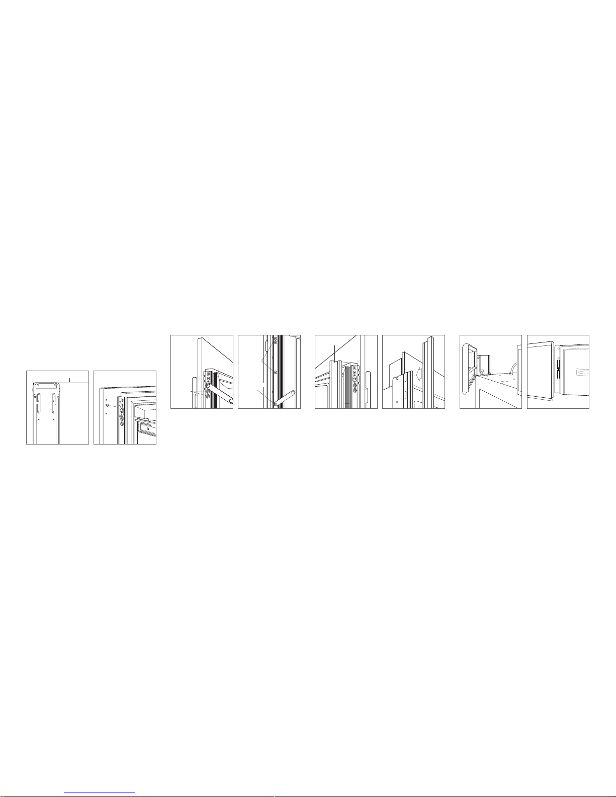
Product Information
Important product information including the model and
serial number are listed on the product rating plate. For
column models, the rating plate is located inside the middle
drawer near the drawer guide opposite the hinge. For tall
and drawer models, the rating plate is located inside the
cabinet, to the left of the upper drawer. Refer to the illustrations below.
If service is necessary, contact your authorized Sub-Zero
dealer.
INTEGRATED REFRIGERATION
Contents
2 Integrated Refrigeration
3 Opening Dimensions
3 Electrical
4 Plumbing
4 Preparation
4 Anti-Tip Bracket
5 Placement
5 Alignment
6 Water Line
6 Custom Panels
7 Panel Installation
8 Completion
Tools and Materials
• Screwdrivers—standard, Phillips and Torx.
• Power drill.
• Drill bits (masonry bits required for concrete installation).
• Standard socket and wrench set.
• .6 m and 1.2 m levels.
• Tubing cutter.
• .9 m of
1
/4" OD copper, braided stainless steel or
PEX tubing.
• Saddle valve.
• Material to protect home, ooring and cabinetry during
installation.
Important Note
To ensure this product is installed and operated as safely
and efciently as possible, take note of the following types
of highlighted information throughout this guide:
IMPORTANT NOTE highlights information that is especially
important.
CAUTION indicates a situation where minor injury or product
damage may occur if instructions are not followed.
WARNING states a hazard that may cause serious injury or
death if precautions are not followed.
Column models.
Tall and drawer models.
RATING
PLATE
RATING
PLATE

subzero.com | 3
SITE PREPARATION
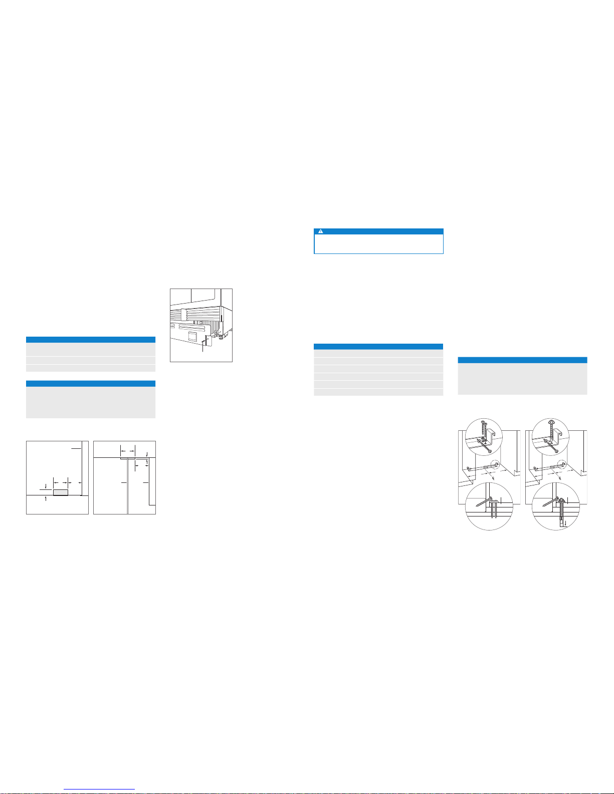
Opening Dimensions
INTEGRATED MODELS
635 mm
OPENING
DEPTH
A
OPENING WIDTH
635 mm
OPENING DEPTH
B
OPENING
HEIGHT
TOP VIEW
FRONT VIEWSIDE VIEW
OPENING DIMENSIONS A B
COLUMN MODELS WIDTH HEIGHT
ICBIC-18FI 457 mm 2134 mm
ICBIC-24R, ICBIC-24FI 610 mm 2134 mm
ICBIC-30RID, ICBIC-30FI 762 mm 2134 mm
ICBIC-36RID 914 mm 2134 mm
TALL MODELS A B
ICBIT-30RID, ICBIT-30CIID 762 mm 2134 mm
ICBIT-36CIID 914 mm 2134 mm
DRAWER MODELS A B
ICBID-30RP, ICBID-30CI 762 mm 876 mm
ICBID-36CI 914 mm 876 mm
The depth of each integrated model is 610 mm. Allow for
panel thickness when planning the nished opening depth.
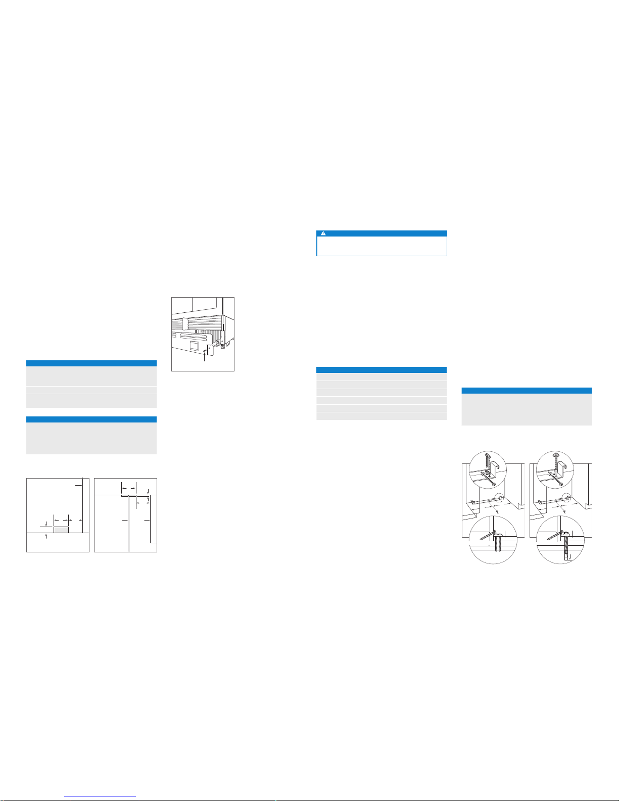
Electrical
Installation must comply with all applicable electrical codes.
The electrical supply must be located within the shaded
area shown in the illustration and chart below. A separate
circuit, servicing only this appliance is required. A ground
fault circuit interrupter (GFCI) is not recommended and may
cause interruption of operation.
This appliance is equipped with an appliance inlet type
device. The appliance inlet is located at the bottom rear of
the appliance. When replacing the power cord verify the
replacement cord is rated HO5VV-F3G1.0 or equivalent to
ensure safe operation.
CAUTION
The outlet must be checked by a qualied electrician to
be sure that it is wired with the correct polarity. Verify
that the outlet is properly grounded (earthed).
WARNING
Do not use an extension cord, two-prong adapter or
remove the power cord ground prong.
ELECTRICAL REQUIREMENTS
Power Supply 220-240 V AC, 50/60 Hz
Circuit Breaker 10 amp
Receptacle grounding-type (earthed)
ELECTRICAL SUPPLY LOCATION
WIDTH A
457 mm Models 152 mm
610 mm Models 241 mm
762 mm Models 318 mm
914 mm Models 394 mm
A
6 mm
108
mm
114 mm
FRONT VIEW
FLOOR
LEFT SIDE
OF OPENING
E
Electrical supply location.
Electrical
Shock
Hazard
Plug power cord directly into a properly
grounded (earthed) outlet.
Do not defeat the grounding (earthing)
nature of the plug.
Do not use adapter or extension cord.
Failure to follow these instructions could
cause serious injury or death.
See installation instructions
4 | English subzero.com
SITE PREPARATION
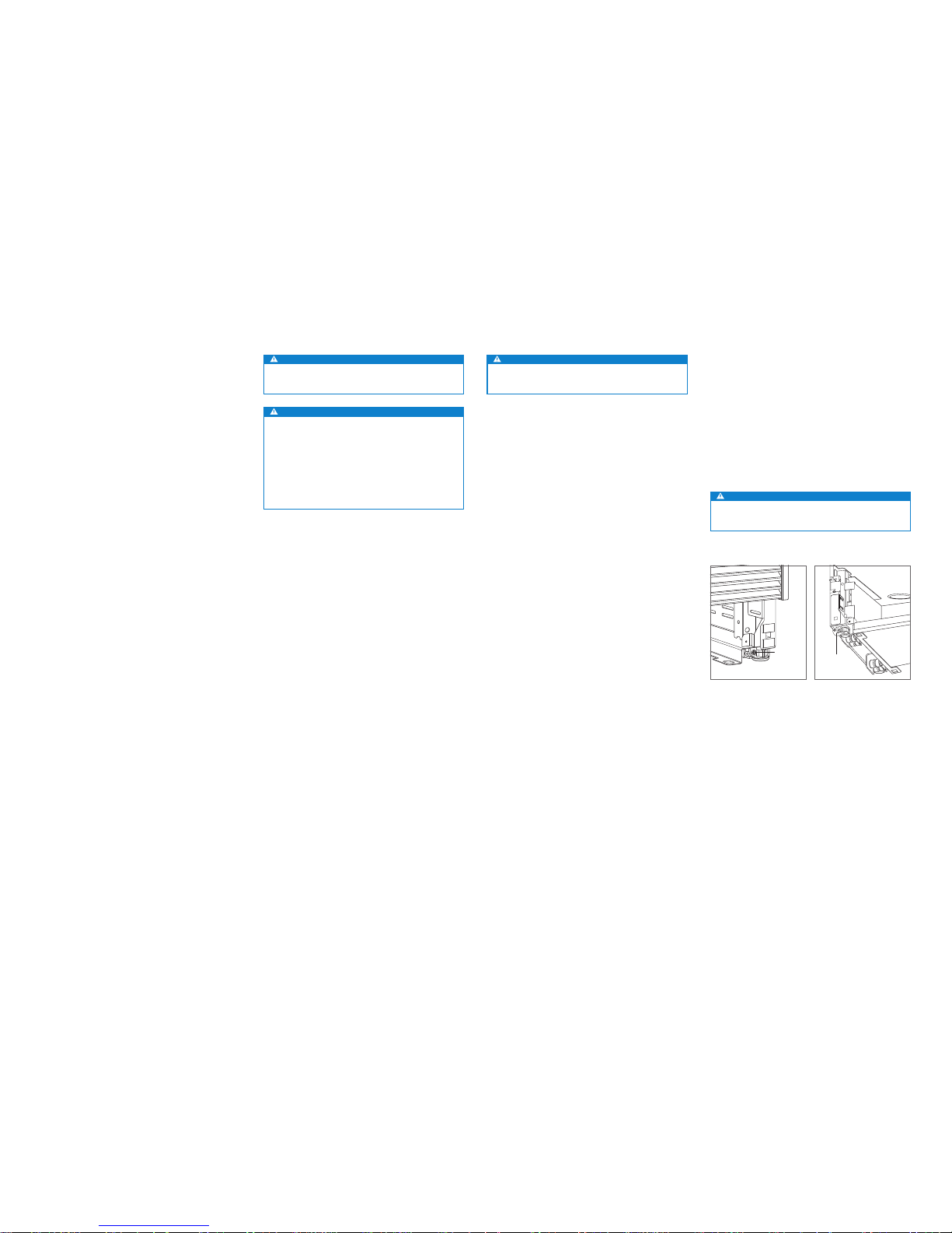
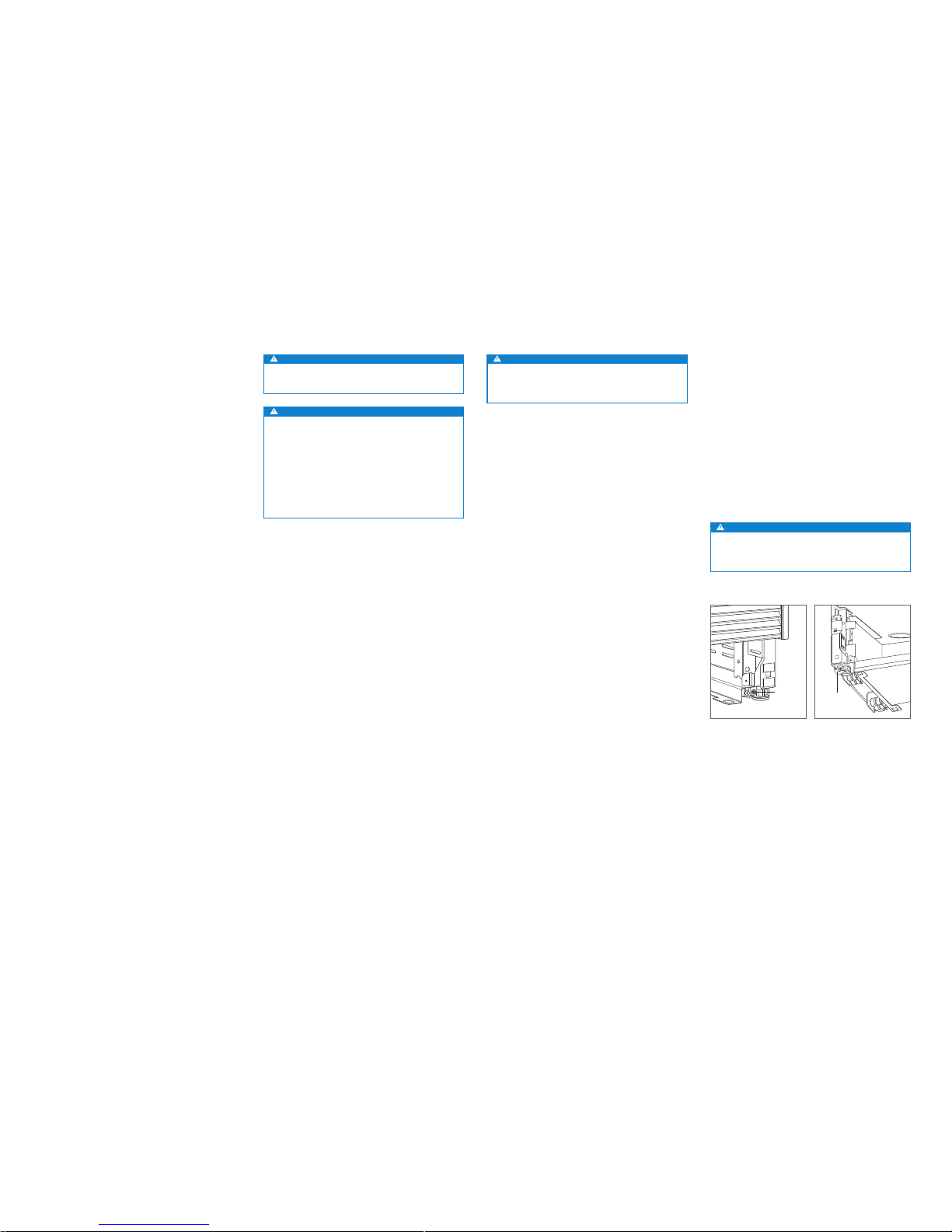
Preparation
Uncrate the unit and inspect for damage. Remove the wood
base and discard shipping bolts and brackets. Remove and
recycle packing materials. Do not discard the kickplate, antitip bracket and hardware.
Remove the kickplate by extracting the two mounting
screws. Refer to the illustration below.
Anti-Tip Bracket
WARNING
To prevent the unit from tipping forward, the anti-tip
bracket must be installed.
The back of the anti-tip bracket must be installed 610 mm
from the front of the unit (without panels).
Use all anti-tip bracket hardware as instructed for wood or
concrete oors.
IMPORTANT NOTE: For wood or concrete oor applications,
if the #12 screws do not hit a wall stud or wall plate, use the
#8 screws and #12 washers with the wall anchors.
IMPORTANT NOTE: In some installations the subooring or
nished oor may necessitate angling the screws used to
fasten the anti-tip bracket to the back wall.
ANTI-TIP HARDWARE
1 Anti-tip bracket
12 #12 x 64 mm pan head screws
4
3
/8"–16 x 95 mm wedge anchors
12 #12 at washers
4 #8–18 x 32 mm truss head screws
4 Nylon Zip-it
®
wall anchors
SCREW
Kickplate removal.
WOOD FLOOR APPLICATION
After properly locating the anti-tip bracket in the opening,
drill pilot holes 5 mm diameter maximum in the wall studs or
wall plate. Use the #12 screws and washers to secure the
brackets. Verify the screws penetrate through the ooring
material and into wall studs or wall plate a minimum of 19
mm. Refer to the illustration and chart below.
CONCRETE FLOOR APPLICATION
After properly locating the anti-tip bracket in the opening,
drill pilot holes 5 mm diameter maximum in the wall studs
or wall plate. Drill 10 mm diameter holes into the concrete a
minimum of 38 mm deep. Use the #12 screws and washers
to secure the brackets to the wall, and use the
3
/8" wedge
anchors to secure the brackets to the oor. Verify the screws
penetrate wall studs or wall plate a minimum of 19 mm.
Refer to the illustration and chart below.
ANTI-TIP BRACKET PLACEMENT
WIDTH A
457 mm Models 229 mm
610 mm Models 305 mm
762 mm Models 318 mm
914 mm Models 457 mm
A
A
SUBFLOORING
WOOD FLOOR
WALL PLATE
FINISHED
FLOORING
A
A
SUBFLOORING
CONCRETE
FLOOR
WALL PLATE
FINISHED
FLOORING
38 mm
min
Wood oor.
Concrete oor.
Plumbing
Installation must comply with all applicable plumbing codes.
The water supply line should be located within the shaded
area shown in the illustrations below. The water supply line
should be connected to the house supply with an easily
accessible shut-off valve. Do not use self-piercing valves.
The water supply line must be ush to the oor and not
interfere with installation of the anti-tip bracket.
An in-line lter is required for models with an ice maker or
water dispenser when water conditions have a high sediment content.
A reverse osmosis system can be used provided there
is constant water pressure of 2.4–8.3 bar supplied to the
unit at all times. A copper line is not recommended for this
application.
PLUMBING REQUIREMENTS
Water Supply Line
1
/4" OD copper, braided
stainless steel or PEX tubing
Water Pressure 2.4–8.3 bar
Excess Water Line for Connection .9 m
WATER SUPPLY LOCATION
WIDTH A
457 mm Models 76 mm
610 mm Models 140 mm
762 mm Models 152 mm
914 mm Models 229 mm
76 mm
FRONT VIEW
FLOOR
TOP VIEW
BACK WALL
13 mm
152
mm
A
WATER
LINE
A
152
mm
RIGHT SIDE
OF OPENING
RIGHT
SIDE OF
OPENING
TOP VIEW
BACK WALL
13 mm
A
WATER
LINE
152
mm
RIGHT
SIDE OF
OPENING
Water supply location (rear). Water supply location (bottom).
subzero.com | 5
SITE PREPARATION
Anti-Tip Bracket
CONCRETE WEDGE ANCHOR INSTALLATION:
1 Drill a 10 mm diameter hole any depth exceeding the
minimum embedment. Clean the hole or drill additional
depth to accommodate drill nes.
2 Assemble the washer and nut ush with the end of
anchor to protect threads. Drive the anchor through the
material to be fastened until the washer is ush with the
surface material.
3 Expand the anchor by tightening the nut 3–5 turns past
hand-tight position or to 34 newton-meters of torque.
WARNING
Verify there are no electrical wires or plumbing in the
area which the screws could penetrate.
CAUTION
Always wear safety glasses and use other necessary protective devices or apparel when installing or
working with anchors.
Anchors are not recommended for use in lightweight
masonry material such as block or brick, or for use in
new concrete which has not had sufcient time to cure.
The use of core drills is not recommended to drill holes
for the anchors.
INSTALLATION
Placement
CAUTION
Before moving the unit into position, secure the door/
drawers closed and protect any nished ooring.
Use an appliance dolly to move the unit near the opening.
The front leveling legs are extended below the front rollers to
improve stability during placement. Once the unit is placed
in front of the opening, completely retract the front leveling
legs to allow the unit to be rolled into position. Front and
rear leveling legs can be adjusted from the front once the
unit is positioned.
If the unit has been on its back or side, it must stand upright
for a minimum of 24 hours before connecting power.
Plug the power cord into the grounded outlet and roll the
unit into position. Verify the anti-tip bracket is properly
engaged.
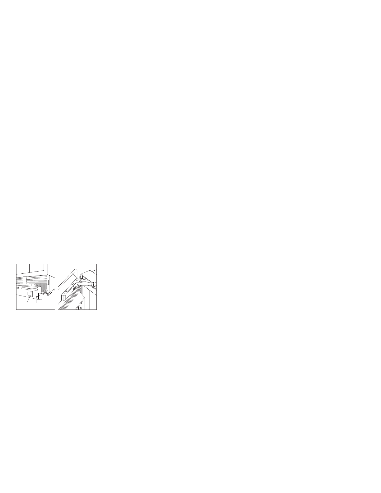
Alignment
LEVELING
Once the unit is in position, height adjustment can be made
from the front. Using a Phillips drive, turn clockwise to raise
the unit or counterclockwise to lower. Use the lowest torque
setting when using a power drill. Do not turn the leveling
legs by hand. Refer to the illustrations below.
When the unit is properly leveled, door/drawer adjustments
are less likely to be necessary.
IMPORTANT NOTE: Level the unit to the oor, not sur-
rounding cabinetry. This could affect the operation of the
unit, such as door closing.
WARNING
To reduce the possibility of the unit tipping forward,
the front leveling legs must be in contact with the oor.
FRONT
LEG
ADJUSTMENT
REAR LEG
ADJUSTMENT
Front adjustment.
Rear adjustment.
6 | English subzero.com
Custom Panels
For integrated models, custom door panels and handle
hardware must be installed. Stainless steel panels are available through an authorized Sub-Zero dealer.
The thickness of the custom panel can vary. A minimum
16 mm thick panel is required, but the thickness can be
increased provided it does not exceed the maximum panel
weight indicated in the chart below. The depth of each
integrated model is 610 mm. Allow for panel thickness when
planning the nished opening depth.
PANEL REQUIREMENTS
COLUMN MAX WEIGHT
457 mm Models 20 kg
610 mm Models 27 kg
762 / 914 mm Models 34 kg
TALL (DOOR) MAX WEIGHT
762 mm Models 22 kg
914 mm Models 27 kg
DRAWER MAX WEIGHT
All Drawer Panels 7 kg
PANEL THICKNESS MINIMUM
All Panels 16
Reveals between panels can vary, 3 mm reveals are typical.
CAUTION
When installing a panel thicker than 25 mm, the 90°
stop may be required to prevent damage to the unit
and adjacent cabinetry.
CAUTION
As reveals between cabinetry and the unit decrease,
severe nger pinching can occur while door is closing.
Finish all sides of custom panels. They will be visible when
the door is open.
D-style handles are recommended. Stainless steel tubular
and pro handles are avail able through an authorized
Sub-Zero dealer. Door handles must be located near the
edge of the panel opposite the hinge and should be centered top to bottom. Drawer handles must be located near
the top edge of each panel.
DUAL INSTALLATION
When installing two units side by side in a dual installation, the opening width is the width of the two units added
together. A dual installation kit will be required for this
installation.
Dual installation kits are available through an authorized
Sub-Zero dealer. For questions regarding the installation,
contact your authorized Sub-Zero dealer.
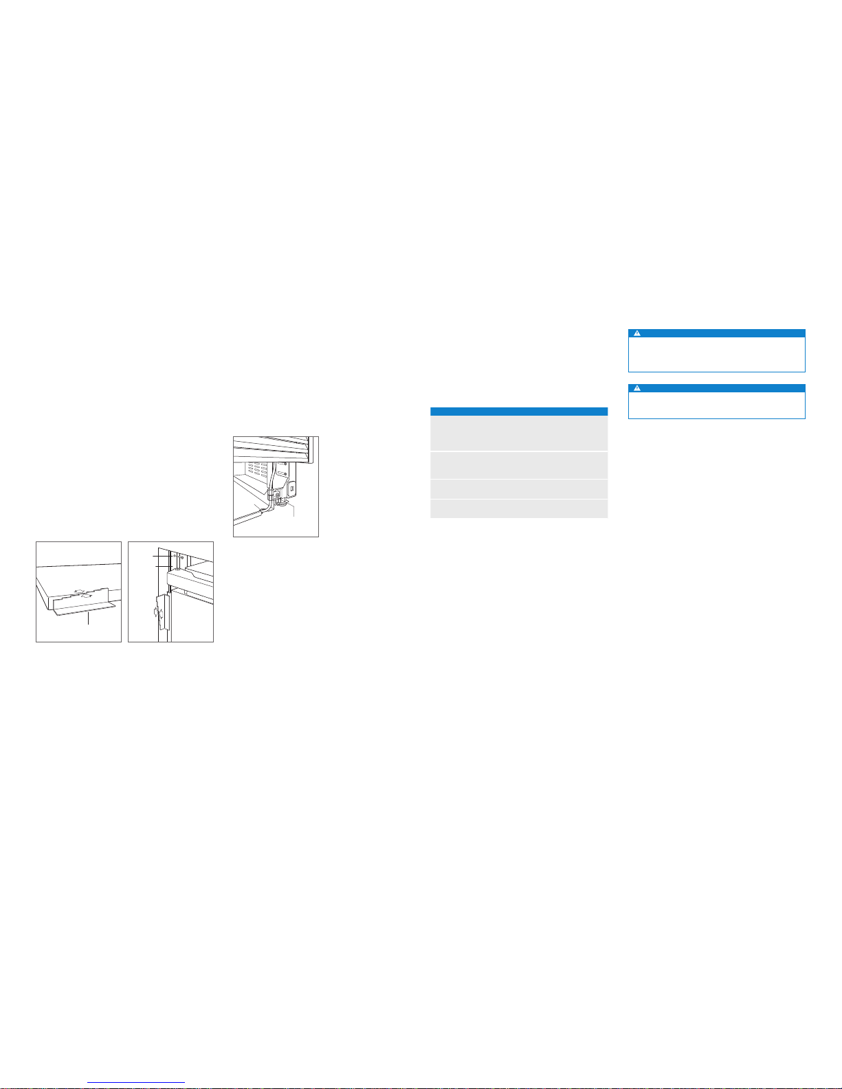
PANEL INSTALLATIONINSTALLATION
Water Line
Purge the water line prior to nal connection to the unit. This
will remove any debris that may be present in the tubing
from installing the new water line. Connect the plastic tubing
from the unit to the house water supply line with the tting
connection kit provided. Check all water line ttings for
leaks.
Locate the water line in the notch as shown in the illustration
below.
IMPORTANT NOTE: Water lines can not be exposed to
freezing temperatures.
WATER LINE
CONNECTION
NOTCH
Water line.
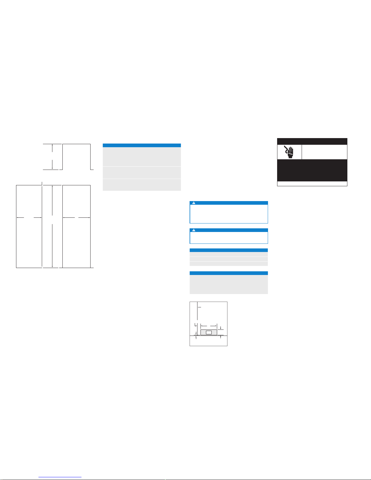
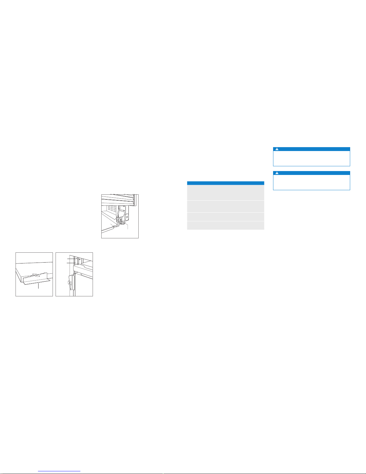
Alignment
DEPTH ADJUSTMENT
Adjust the depth of the unit to t ush with surrounding
cabinetry. Follow these steps for a precision t:
1 Place decorative panel on a protected work surface.
Place the panel thickness gauge next to the panel to
determine which notch corresponds with the panel thickness. Once the proper notch has been determined, mark
that notch with a marker.
2 With the door closed, position the top of the unit using
the panel thickness gauge. Insert a #8 x 13 mm stainless
steel screw above the hinge, then insert a #8 x 13 mm
pan head screw on the handle side of the unit. For narrower units, the door may need to be opened to access
the handle side screw location. Repeat the process to
align the bottom.
ANCHORING
Once the top and bottom are aligned, verify doors and
drawers open properly, then install remaining screws in each
side trim.
PANEL THICKNESS
GAUGE
FRONT OF
UNIT
CABINETRY
FACE
FRAME
SCREW
SIDE TRIM
Panel thickness.
Unit depth.
subzero.com | 7
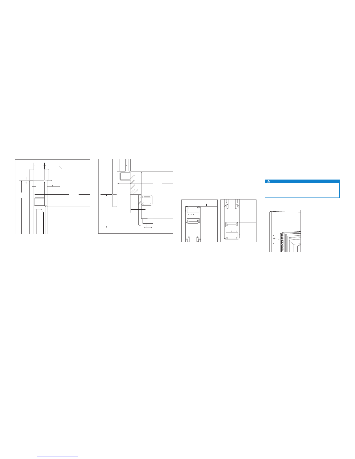
PANEL INSTALLATION
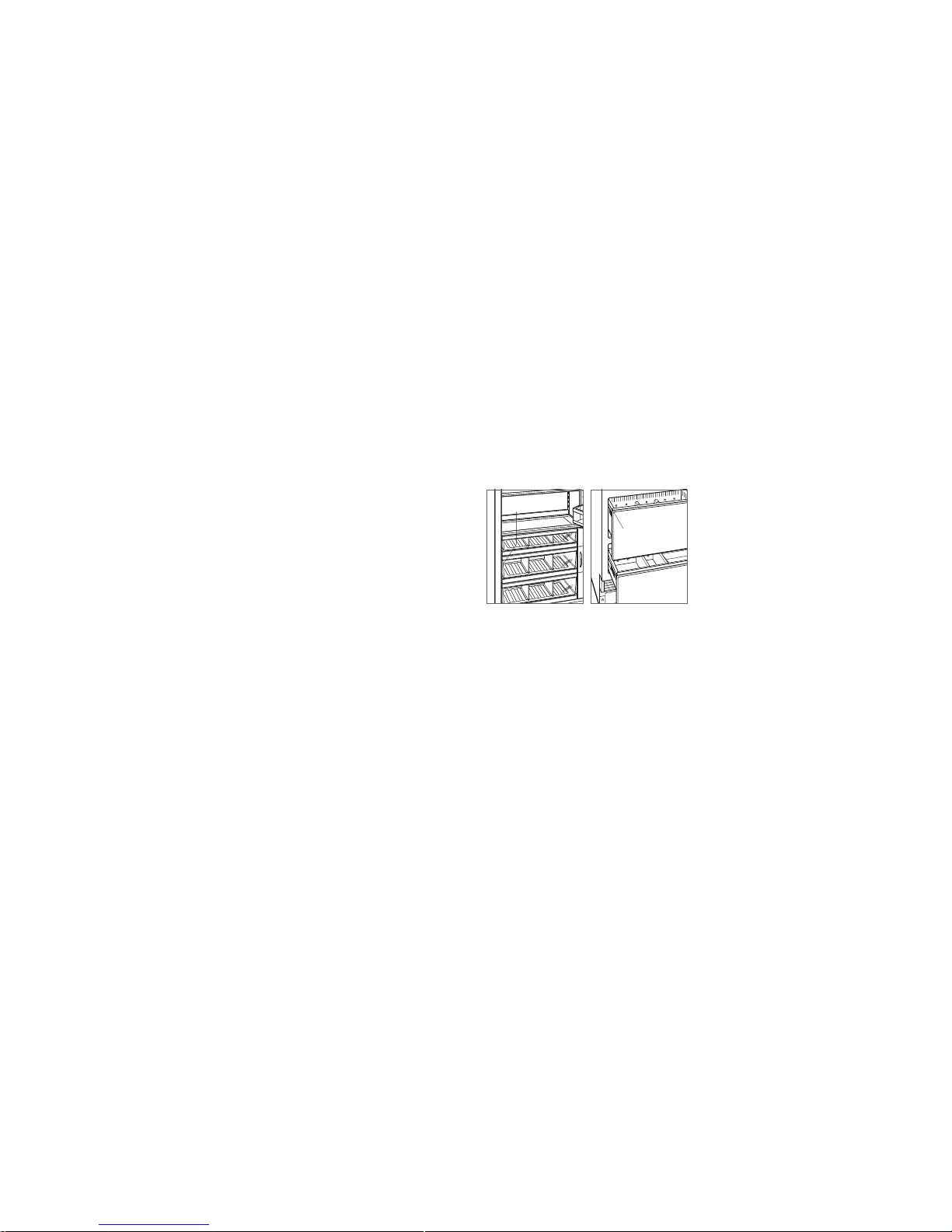
Custom Panels
DOOR PANEL HEIGHT
The height of the custom door panel can extend beyond the
typical panel height, provided it does not exceed the weight
limit. Refer to the illustration below.
TOE KICK CLEARANCE
The height of the toe kick area can extend beyond the
typical toe kick height, provided it does not exceed the
dimensions in the illustration below.
610 mm
TO BACK OF UNIT
VENTED
LOUVERS
HINGE
DOOR
PANEL
29 mm
MAX
TOE KICK
ADJUSTMENT
A DECORATIVE TOE KICK
CANNOT EXTEND
BEYOND THIS PLANE
102 mm
TO
152 mm
FROM FLOOR
Toe kick area—side view.
45
mm
A DECORATIVE VALANCE
CANNOT EXTEND
BEYOND THIS PLANE
DOOR
PANEL
HINGE
610 mm
TO BACK OF UNIT
2134
mm
3 mm
Upper valance (column and tall models)—side view.
Panel Installation
DOOR PANEL INSTALLATION
Typical panel dimensions are based on a 2134 mm nished
height with 3 mm reveals. Template placement must be
adjusted for panels exceeding typical dimensions.
For tall models, the door panel should be installed rst,
followed by the upper then lower drawer panel.
Place the panel face down on a protected work surface.
Position the template ush with the top and sides of the
panel. Verify the correct side of the template is being used,
then mark and drill holes. Refer to the illustration below.
For tall models, align the notch in the template with the
bottom of the door panel, then mark and drill holes. Refer to
the illustration below.
Use the T-20 torx drive provided, to partially insert a #8 x 13
mm screw into the second hole from the top on each side of
the panel. The screws should be approximately 4 mm proud
of the panel and will support the weight of the panel during
installation.
Align the support screws on the back of the panel with the
slotted holes on both door mounting brackets. Opening
the door slightly may help with alignment. Once the panel
is supported by the screws, partially insert a #8 x 13 mm
screw into the second hole from the bottom on each side of
the panel, but do not tighten.
CAUTION
As the reveal between cabinets and the unit decreases,
the potential exists for severe nger pinching if ngers
are placed in the opening when the door is closing.
BACK OF
DOOR PANEL
Door panel mounting.
BOTTOM OF
DOOR PANEL
USE TABS FOR HINGE
SIDE PANEL EDGE ON
DUAL INSTALLATION
TOP OF
DOOR PANEL
84" APPLICATION
83 7/8" ACTUAL
TOP OF DOOR PANEL
BOTTOM OF
DOOR PANEL
EDGE OF DOOR PANEL
USE TABS FOR HINGE
SIDE PANEL EDGE ON
DUAL INSTALLATION
TOP OF
DOOR PANEL
84" APPLICATION
83 7/8" ACTUAL
EDGE OF DOOR PANEL
BOTTOM OF
DOOR PANEL
Door panel template—top. Door panel template—bottom
(tall models only).
8 | English subzero.com
INSTALLATION
Completion
DOOR TRIM INSTALLATION
After panels have been adjusted, install the decorative side
trim to the door/drawers. To install, align the trim with the
bracket on the side of the door/drawer and snap into place,
pushing the trim toward the back of the panel. Refer to the
illustration below.
SIDE TRIM INSTALLATION
Install the decorative trim strip to the handle side of tall
and column models. The side trim snaps over the bracket
attached to the handle side of the unit. Refer to the illustration below.
TOP TRIM INSTALLATION
Identify the top trim strips by the notch on one end at the
bottom; this trim strip ts on the hinge side of the unit.
Insert the outer end of each trim strip behind the vertical
side trim. Engage the snap in the plastic side bracket and
slide the panel as far to the outside as possible. Refer to the
illustration below.
Rotate the inner end of each panel into the side ange of
the center shroud, next to the water lter access door. Press
on the trim strip to snap into place. Refer to the illustration
below.
Inner top trim.
Outer top trim.
DOOR TRIM
Door trim.
Side trim.
PANEL INSTALLATION
PANEL ADJUSTMENT
Close the door and/or drawers, now adjustments can be
made to align panels and reveals.
For side-to-side adjustment, move panels side to side, then
install and tighten all mounting screws.
For up-and-down and in-and-out adjustments, slightly
loosen the bracket screws. Depending on the level of
adjustment required, it may be helpful to loosen all of the
bracket screws which will allow for maximum adjustment.
Once the bracket screws are loosened, rotate the cams
to make adjustments. After adjustments have been made,
tighten all bracket screws. Refer to the illustrations below.
BRACKET
SCREWS
IN-AND-OUT
CAM
BRACKET
SCREWS
UP-AND-DOWN
CAM
In-and-out adjustment.
Up-and-down adjustment.
Panel Installation
DRAWER PANEL INSTALLATION
Place the panel face down on a protected work surface.
Position the template ush with the top and sides of the
panel. Verify the correct side of the template is being used,
then mark and drill holes. Refer to the illustration below.
Use the T-20 torx drive provided, to partially insert a #8 x 13
mm screw into the second hole from the top on each side of
the panel. The screws should be approximately 4 mm proud
of the panel and will support the weight of the panel during
installation.
Align the support screws on the back of the panel with the
slotted holes on both drawer mounting brackets. Refer
to the illustration below. Opening the drawer slightly may
help with alignment. Once the panel is supported by the
screws, partially insert a #8 x 13 mm screw into the second
hole from the bottom on each side of the panel, but do not
tighten.
WER PANEL
TOP HOLES
FOR UPPER
AND LOWER
DRAWERS
TOP OF
DRAWER PANEL
LEFT EDGE OF DRAWER PANEL
TOP OF DRAWER PANEL
BACK OF
DRAWER PANEL
Drawer panel template—top. Drawer panel mounting.
subzero.com | 9
Completion
KICKPLATE INSTALLATION
Position the kickplate and install using the two mounting
screws. Refer to the illustration below. Kickplate must
be removable for service. The oor cannot interfere with
removal.
A maximum 152 mm decorative kickplate can be attached
to the factory-installed kickplate. The two rows of vented
louvers can be covered if door panel is a minimum 102 mm
from nished oor.
To install a decorative kickplate, remove paper backing from
the magnets and attach decorative kickplate to magnets.
Magnets may also be tacked into position to increase adhesion. Magnets will allow decorative kickplate to be removed,
if necessary.
Turn power on by touching ‘power’ on the control panel.
90° DOOR STOP
A 105° door stop is built into the hinges of tall and column
units. To limit the door to 90°, open the door slightly less
than 90°, then use a standard screwdriver blade to remove
the existing clips from each hinge. Locate the 90° clips from
inside the plastic bag containing product literature, then
insert the 90° clips onto each hinge. Refer to the illustration
below.
INSTALLATION
SCREWMAGNET
CLIP
Kickplate installation.
90° door stop.
Sub-Zero, Sub-Zero & Design, Dual Refrigeration, Constant Care, The Living Kitchen, Great American Kitchens The Fine Art of Kitchen Design, and Ingredients are registered trademarks and service marks of Sub-Zero, Inc. Wolf, Wolf & Design, Wolf Gourmet, W & Design and the color red as applied to knobs are registered trademarks and service marks of Wolf Appliance,
Inc. (collectively, the “Company Marks.”) All other trademarks or registered trademarks are property of their respective owners in the United States and other countries.
2 | Español subzero.com
Información sobre el producto
En la placa de datos del producto encontrará información
importante, incluyendo el modelo y el número de serie. En
los modelos de columna, la placa de datos está situada
en el interior del cajón intermedio, próxima a la guía del
cajón frente a la bisagra. En los modelos de gran altura y
con cajones, la placa de datos está situada en el interior
del armario, a la izquierda del cajón superior. Observe las
siguientes ilustraciones.
Si necesita recurrir a un servicio técnico, póngase en contacto con su distribuidor de Sub-Zero autorizado.
REFRIGERACIÓN INTEGRABLE
Índice
2 Refrigeración integrable
3 Medidas de la cavidad
3 Potencia
4 Fontanería
4 Preparación
4 Soporte antivuelco
5 Colocación
5 Alineación
6 Conducto de agua
6 Paneles a medida
7 Instalación del panel
8 Comprobación
Herramientas y materiales
• Destornilladores: estándar, Phillips y Torx.
• Taladro.
• Brocas (se necesitarán brocas de mampostería para una
instalación determinada).
• Juego de llaves y llaves de vaso estándar.
• Niveles de 0,6 m y 1,2 m.
• Instrumento especial para cortar el tubo.
• Tubo de 0,9m de
1
/4" de cobre OD, acero inoxidable
trenzado o de PEX.
• Válvula de montaje.
• Material para proteger la casa, el suelo y los armarios de
cocina durante la instalación.
Nota importante:
Para garantizar que este producto se instala y funciona de
la forma más ecaz y segura posible, tenga en cuenta la
información que se destaca en esta guía:
Cuando aparece NOTA IMPORTANTE, se resalta información
que resulta especialmente importante.
PRECAUCIÓN indica una situación en la que se pueden
sufrir heridas leves o provocar daños al producto si no se
siguen las instrucciones.
AVISO indica peligro de que se produzcan heridas perso-
nales graves o incluso la muerte si no se siguen las precauciones especicadas.
Modelos de columna.
Modelos altos y con cajones.
PLACA
DE DATOS
PLACA
DE DATOS
subzero.com | 3
PREPARACIÓN DEL SITIO
Medidas de la cavidad
MODELOS INTEGRABLES
635 mm
PROFUNDIDAD DE
LA CAVIDAD
A
ANCHURA DE LA CAVIDAD
635 mm
PROFUNDIDAD DE
LA CAVIDAD
B
ALTURA DE
LA CAVIDAD
VISTA SUPERIOR
VISTA FRONTALVISTA LATERAL
MEDIDAS DE LA CAVIDAD A B
MODELOS DE COLUMNA ANCHURA ALTURA
ICBIC-18FI 457mm 2134mm
ICBIC-24R, ICBIC-24FI 610mm 2 134mm
ICBIC-30RID, ICBIC-30FI 762mm 2 134mm
ICBIC-36RID 914mm 2 134mm
MODELOS ALTOS A B
ICBIT-30RID, ICBIT-30CIID 762mm 2 134mm
ICBIT-36CIID 914mm 2 134mm
MODELOS CON CAJÓN A B
ICBID-30RP, ICBID-30CI 762mm 876mm
ICBID-36CI 914mm 876mm
La profundidad de los modelos integrables es de 610mm.
Tenga en cuenta el grosor del panel cuando calcule la profundidad de la cavidad acabada.
Potencia
La instalación debe cumplir con toda la normativa local
aplicable en materia de electricidad.
La toma eléctrica debe situarse en el área sombreada en
la ilustración y la tabla que se incluyen a continuación. Se
necesita un circuito independiente para esta unidad. No se
recomienda utilizar un interruptor de circuito de fallos de
toma de tierra (GFCI), ya que puede interrumpir el funcionamiento de la unidad.
El aparato está equipado con un dispositivo de entrada. La
entrada del aparato se encuentra en la parte inferior trasera
del dispositivo. Para cambiar el cable eléctrico es necesario
comprobar que el cable nuevo cuente con clasicación
HO5VV-F3G1.0 o una clasicación equivalente que garantice el funcionamiento seguro.
PRECAUCIÓN
La toma de corriente debe ser revisada por un electricista
cualicado para comprobar que la conexión se ha realizado con la polaridad correcta. Compruebe que la toma
de corriente está conectada a tierra de manera correcta.
AVISO
No utilice alargadores ni adaptadores, ni quite la clavija
de toma a tierra del cable eléctrico.
REQUISITOS ELÉCTRICOS
Alimentación eléctrica 220-240 V CA, 50/60 Hz
Magnetotérmico 10 amperios
Enchufe con toma de tierra
UBICACIÓN DE LA ALIMENTACIÓN ELÉCTRICA
ANCHURA A
Modelos de 457mm 152mm
Modelos de 610mm 241mm
Modelos de 762mm 318mm
Modelos de 914mm 394mm
A
6 mm
108
mm
114 mm
VISTA FRONTAL
SUELO
LADO IZQUIERDO
DE LA CAVIDAD
E
Ubicación de la alimentación
eléctrica.
Peligro de
descarga
eléctrica
Enchufe el cable eléctrico directamente en una toma
con conexión a tierra.
No manipule la conexión a tierra del enchufe.
No utilice adaptadores ni alargadores.
Si no sigue estas instrucciones, existe riesgo de que
se produzcan heridas graves o incluso la muerte.
Ver instrucciones de instalación
4 | Español subzero.com
PREPARACIÓN DEL SITIO
Preparación
Desembale la unidad y compruebe si tiene algún daño o
desperfecto. Retire la base de madera y extraiga todos los
tornillos y soportes del paquete. Quite y recicle los materiales de embalaje. No tire el zócalo, el soporte antivuelco ni
las piezas de montaje.
Retire el zócalo extrayendo los dos tornillos de montaje.
Consulte la siguiente ilustración.
Soporte antivuelco
AVISO
Debe instalarse el soporte antivuelco para evitar que la
unidad se incline hacia adelante.
La parte trasera del soporte antivuelco debe instalarse a
610mm de la parte delantera de la unidad (sin paneles).
Utilice todas las piezas del soporte antivuelco tal y como
se indica en las instrucciones para suelos de madera o de
hormigón.
NOTA IMPORTANTE: para aplicaciones en madera o en un
suelo determinado, en caso de que los tornillos del n.º 12
no alcancen el montante o la placa de pared, utilice tornillos
del n.º 8 y arandelas del n.º 12 con los anclajes para pared.
NOTA IMPORTANTE: en algunas instalaciones es posible
que, debido al tipo de suelo o acabado de este, sea necesario colocar los tornillos inclinados para sujetar el soporte
antivuelco a la pared trasera.
PIEZAS ANTIVUELCO
1 Soporte antivuelco
12 Tornillos de cabeza plana del n.º 12 (64 mm)
4 Anclajes de expansión de 16 x 95 mm –
3
/8"
12 Arandelas planas del n.º 12
4 Tornillos de cabeza ovalada de del n.° 8 (18 x 32 mm)
4 Anclajes para pared de nailon Zip-it
®
TORNILLO
Extracción del zócalo.
APLICACIÓN EN SUELO DE MADERA
Tras colocar correctamente el soporte antivuelco en la
cavidad, perfore oricios guía de 5mm de diámetro como
máximo en los montantes de pared o en la placa de pared.
Utilice arandelas y tornillos del n.º 12 para jar los soportes.
Compruebe que los tornillos penetren en el material del
suelo y en los montantes de pared o en las placas un
mínimo de 19 mm. Consulte la ilustración y la tabla que se
incluyen a continuación.
APLICACIÓN EN SUELO DE HORMIGÓN
Tras colocar correctamente el soporte antivuelco en la
cavidad, perfore oricios guía de 5mm de diámetro como
máximo en los montantes de pared o en la placa de pared.
Realice oricios de 10 mm de diámetro en el hormigón con
una profundidad mínima de 38 mm. Utilice arandelas y tornillos del n.º 12 para jar los soportes a la pared, y anclajes
de expansión de
3
/8" (9,5 mm) para jar los soportes al
suelo. Compruebe que los tornillos penetren en los montantes de pared o en las placas un mínimo de 19 mm. Consulte la ilustración y la tabla que se incluyen a continuación.
COLOCACIÓN DEL SOPORTE ANTIVUELCO
ANCHURA A
Modelos de 457 mm 229 mm
Modelos de 610 mm 305 mm
Modelos de 762 mm 318 mm
Modelos de 914 mm 457 mm
A
A
TIPO DE SUELO
SUELO DE MADERA
PLACA DE PARED
SUELO
ACABADO
A
A
TIPO DE SUELO
SUELO DE
HORMIGÓN
PLACA DE PARED
SUELO
ACABADO
38 mm
min
Suelo de madera.
Suelo de hormigón.
Fontanería
La instalación debe cumplir con toda la normativa local
aplicable en materia de fontanería.
La toma de agua puede situarse en el área sombreada de
las siguientes ilustraciones. El conducto de abastecimiento
de agua se debe conectar al suministro de la casa con
una válvula de cierre de fácil acceso. No utilice conexiones
auto-perforantes. El conducto del agua debe empotrarse
en el suelo para que no interera en la instalación de los
soportes antivuelco.
En los modelos con fabricador de cubitos de hielo o dispensador de agua, es necesario un ltro en la toma para que
no afecten al aparato los sedimentos que, en ocasiones, el
agua puede arrastrar.
Es posible utilizar un sistema de ósmosis invertido, siempre
y cuando la presión de agua que llegue a la unidad se
mantenga de forma constante entre 2,4 bar y 8,3 bar. No se
recomienda utilizar tubos de cobre para esta aplicación.
REQUISITOS DE FONTANERÍA
Conducto de abastecimiento de agua Tubo de 1/4" de cobre
OD, acero inoxidable
trenzado o de PEX
Presión del agua 2,4–8,3 bares
Conducto de agua sobrante para
conexión
0,9 m
UBICACIÓN DE LA TOMA DE AGUA
ANCHURA A
Modelos de 457 mm 76 mm
Modelos de 610 mm 140 mm
Modelos de 762 mm 152 mm
Modelos de 914 mm 229 mm
76 mm
VISTA FRONTAL
SUELO
VISTA SUPERIOR
PARED TRASERA
13 mm
152
mm
A
CONDUCTO
DE AGUA
A
152
mm
LADO DERECHO
DE LA CAVIDAD
LADO
DERECHO
DE LA
CAVIDAD
VISTA SUPERIOR
TRASERA
13 mm
A
CONDUCTO
DE AGUA
152
mm
LADO
DERECHO
DE LA
CAVIDAD
Ubicación de la toma de agua
(trasera).
Ubicación de la toma de agua
(superior).
subzero.com | 5
PREPARACIÓN DEL SITIO
Soporte antivuelco
INSTALACIÓN DE ANCLAJES DE EXPANSIÓN PARA
HORMIGÓN:
1 Haga un agujero de 10 mm de diámetro con una profun-
didad superior al incrustado mínimo. Limpie el oricio o
continúe taladrando para hacer que el oricio sea más
profundo y quepan en él los residuos.
2 Coloque la arandela y la tuerca al nivel del extremo del
anclaje para proteger las roscas. Inserte el anclaje en el
material en el que debe atornillarse hasta que la arandela
quede nivelada con el material de la supercie.
3 Extienda el anclaje mediante una llave que sirva para
apretar la tuerca de 3 a 5 vueltas más de su posición
lograda con el apriete manual o hasta 34 Newton metros
de par.
AVISO
Compruebe que no haya cables eléctricos ni tuberías
en el área en la que se van a introducir los tornillos.
PRECAUCIÓN
Lleve siempre gafas de seguridad y utilice cualquier otro dispositivo o ropa de protección que sea
necesario cuando esté instalando o trabajando con
anclajes.
Se recomienda no utilizar los anclajes en material de
mampostería poco pesado, por ejemplo, bloques o
ladrillos, ni utilizarlo en hormigón fresco que no se haya
secado el tiempo suciente. No se recomienda utilizar
brocas huecas para hacer oricios para los anclajes.
INSTALACIÓN
Colocación
PRECAUCIÓN
Antes de desplazar la unidad para colocarla en su sitio,
asegúrese de que las puertas o cajones estén cerrados
y proteja el acabado del suelo.
Utilice una plataforma rodante para desplazar la unidad
hasta la cavidad. Las patas de nivelación delanteras sobresalen por debajo de las ruedas delanteras para mejorar la
estabilidad durante su colocación. Una vez colocada la
unidad en la parte delantera de la cavidad, repliegue completamente las patas de nivelación delanteras para permitir
que la unidad se pueda colocar en la posición adecuada. Las patas de nivelación delanteras y traseras
pueden ajustarse desde la parte delantera cuando la unidad
ya esté colocada.
Si la unidad ha estado boca abajo o sobre uno de los
lados, debe permanecer en posición vertical como mínimo
24horas antes de conectarla a la alimentación.
Enchufe el cable eléctrico en la toma de conexión a tierra y
coloque la unidad en la posición adecuada. Compruebe que
el soporte antivuelco esté bien jado.
Alineación
NIVELADO
Una vez colocada la unidad, el ajuste de la altura se puede
realizar desde la parte delantera. Con la ayuda de una punta
para tornillos de cabeza Phillips, gire en el sentido de las
agujas del reloj para levantar la unidad y en sentido contrario para bajarla. Utilice el ajuste de torsión más pequeño
si utiliza un taladro. No gire manualmente las patas de nivelación. Observe las siguientes ilustraciones.
Cuando la unidad esté correctamente nivelada, no será tan
necesario realizar los ajustes de las puertas o cajones.
NOTA IMPORTANTE: nivele la unidad con el suelo, y no con
los demás muebles, pues podría afectar al funcionamiento
de la unidad como, por ejemplo, impidiendo que la puerta
se cierre correctamente.
AVISO
Para evitar que la unidad vuelque hacia delante, las
patas de nivelación delanteras deben llegar hasta el
suelo.
AJUSTE
DE LA PATA
DELANTERA
AJUSTE DE LA
PATA TRASERA
Ajuste delantero.
Ajuste trasero.
6 | Español subzero.com
Paneles a medida
En los modelos integrables, se deben instalar tiradores y
paneles de puerta a medida. Podrá encontrar los paneles de
acero inoxidable en un distribuidor de Sub-Zero autorizado.
El grosor del panel a medida puede variar. Será necesario
un panel con un mínimo de 16mm de grosor, medida que
podrá aumentarse siempre y cuando no se supere el límite
de peso del panel indicado en la siguiente tabla. La profundidad de los modelos integrables es de 610mm. Tenga en
cuenta el grosor del panel cuando calcule la profundidad de
la cavidad acabada.
REQUISITOS DEL PANEL
COLUMNA PESO MÁX.
Modelos de 457 mm 20 kg
Modelos de 610 mm 27 kg
Modelos de 762/914mm 34 kg
ALTO (PUERTA) PESO MÁX.
Modelos de 762 mm 22 kg
Modelos de 914 mm 27 kg
CAJÓN PESO MÁX.
Todos los paneles de los cajones 7 kg
GROSOR DEL PANEL MÍNIMO
Todos los paneles 16
Los márgenes entre paneles pueden variar, los de 3mm son
los más corrientes.
PRECAUCIÓN
Si se instala un panel con un grosor de más de 25 mm,
puede que sea necesario un tope de 90º para evitar
que se dañe la unidad y los muebles circundantes.
PRECAUCIÓN
Cuanto menos separación se deje entre los muebles
y la unidad, más daño se puede hacer al pillarse los
dedos en el hueco al cerrar la puerta.
Realice el acabado de todos los lados de los paneles a
medida, pues son áreas que resultarán muy visibles al abrir
la puerta.
Se recomiendan los tiradores en D. Podrá encontrar tiradores tubulares y pro de acero inoxidable en un distribuidor
autorizado de Sub-Zero. Los tiradores de la puerta deben
colocarse cerca del borde del panel en el lado contrario a
la bisagra y centrados. Los tiradores de los cajones pueden
colocarse cerca del borde superior de cada panel.
INSTALACIÓN DOBLE
Si se instalan dos unidades contiguas en una instalación
doble, el ancho de la cavidad es la cavidad de las dos unidades añadidas juntas. Para esta instalación se necesita un
kit de instalación doble.
Podrá encontrar los kits de instalación doble en un distribuidor de Sub-Zero autorizado. Si tiene dudas relacionadas
con la instalación, póngase en contacto con su distribuidor
de Sub-Zero autorizado.
INSTALACIÓN DEL PANELINSTALACIÓN
Conducto de agua
Purgue el conducto de agua antes de conectarlo a la
unidad. Esto hará que se elimine cualquier tipo de suciedad
que pueda haber en el tubo al instalar el nuevo conducto de
agua. Conecte el tubo de plástico de la unidad con la toma
de agua doméstica usando el equipo de conexión suministrado para su instalación. Compruebe si existe alguna fuga
de agua en las conexiones del conducto.
Coloque la línea de agua en la muesca como se muestra en
la siguiente ilustración.
NOTA IMPORTANTE: no se pueden exponer las tomas de
agua a temperaturas de congelación.
CONEXIÓN A LA
TOMA DE AGUA
MUESCA
Conducto de agua.
Alineación
AJUSTE DE LA PROFUNDIDAD
Ajuste la profundidad de la unidad para que quede empotrada con los muebles circundantes. Siga los siguientes
pasos para un ajuste de precisión:
1 Coloque el panel decorativo en una supercie de
trabajo protegida. Coloque el indicador de grosor del
panel al lado del panel para determinar qué muesca se
corresponde con el grosor del panel. Una vez determinada la muesca adecuada, márquela con un marcador.
2 Con la puerta cerrada, coloque la parte superior de la
unidad usando el indicador de grosor del panel. Inserte
un tornillo de acero inoxidable n.º8 x 13mm sobre la
bisagra y, a continuación, inserte un tornillo de cabeza
plana n.º8 x 13mm en el lado del tirador de la unidad.
Para las unidades más estrechas, es posible que sea
necesario abrir la puerta para acceder a la ubicación del
tornillo del lado del tirador. Repita el proceso para alinear
la parte inferior.
ANCLAJE
Una vez alineadas la parte superior e inferior, compruebe
que las puertas y los cajones se pueden abrir correctamente e instale el resto de los tornillos en los bordes
laterales.
INDICADOR DE
GROSOR DEL PANEL
PARTE
DELANTERA
DE LA UNIDAD
MARCO
DELANTERO
DEL
MUEBLE
TORNILLO
BORDE
LATERAL
Grosor del panel.
Profundidad de la unidad.
 Loading...