

Page 1
INTEGRATED REFRIGERATION
INSTALLATION GUIDE
GUÍA DE INSTALACIÓN
GUIDE D’INSTALLATION
GUIDA ALL’INSTALLAZIONE
INSTALLATIONSANLEITUNG
INSTALLATIEHANDLEIDING
Page 2

INTEGRATED REFRIGERATION
Contents
2 Integrated Refrigeration
3 Opening Dimensions
3 Electrical
4 Plumbing
4 Preparation
4 Anti-Tip Bracket
5 Placement
5 Alignment
6 Water Line
6 Panels
7 Panel Installation
8 Completion
Important Note
To ensure this product is installed and operated as safely
and efciently as possible, take note of the following types
of highlighted information throughout this guide:
IMPORTANT NOTE highlights information that is especially
important.
CAUTION indicates a situation where minor injury or product
damage may occur if instructions are not followed.
WARNING states a hazard that may cause serious injury or
death if precautions are not followed.
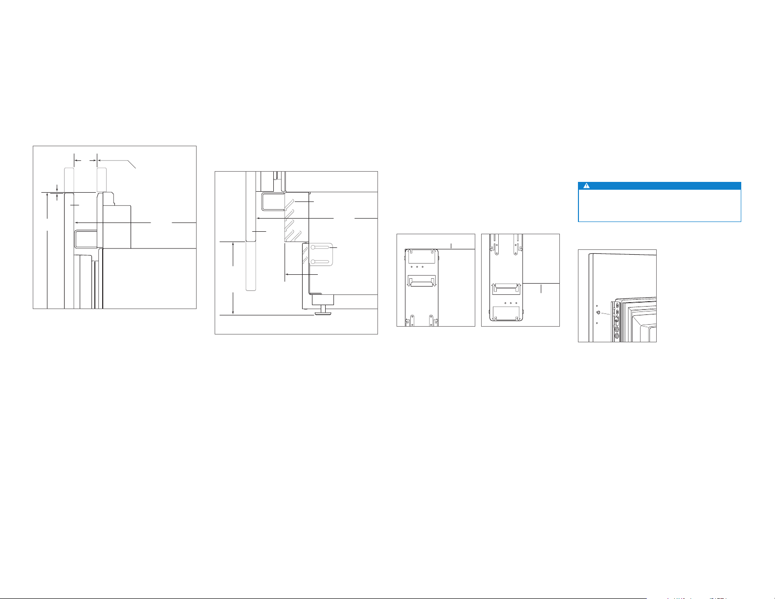
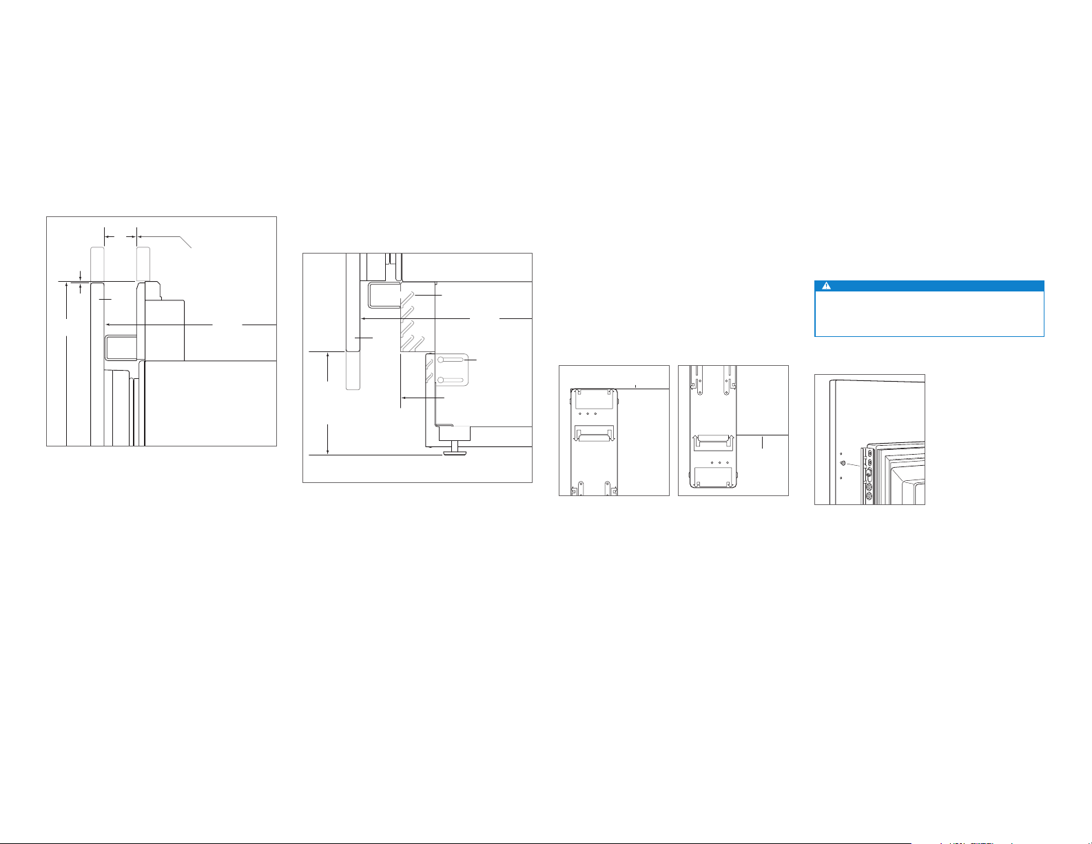
Product Information
Important product information including the model and
serial number are listed on the product rating plate. For
column models, the rating plate is located inside the middle
drawer near the drawer guide opposite the hinge. For tall
and drawer models, the rating plate is located inside the
cabinet, to the left of the upper drawer. Refer to the illustrations below.
If service is necessary, contact your authorized Sub-Zero
dealer.
RATING
PLATE
RATING
PLATE
Column models
Tall and drawer models
Tools and Materials
• Screwdrivers—standard, Phillips and Torx.
• Power drill.
• Drill bits (masonry bits required for concrete installation).
• Standard socket and wrench set.
• .6 m and 1.2 m levels.
• Tubing cutter.
1
• .9 m of
• Saddle valve.
• Material to protect home, ooring and cabinetry during
/4" OD copper, braided stainless steel or
PEX tubing.
installation.
2 | English subzero.com
Page 3
SITE PREPARATION
*89 mm finished returns will be visible and should be finished to match cabinetry
114 mm for outdoor model.
SIDE
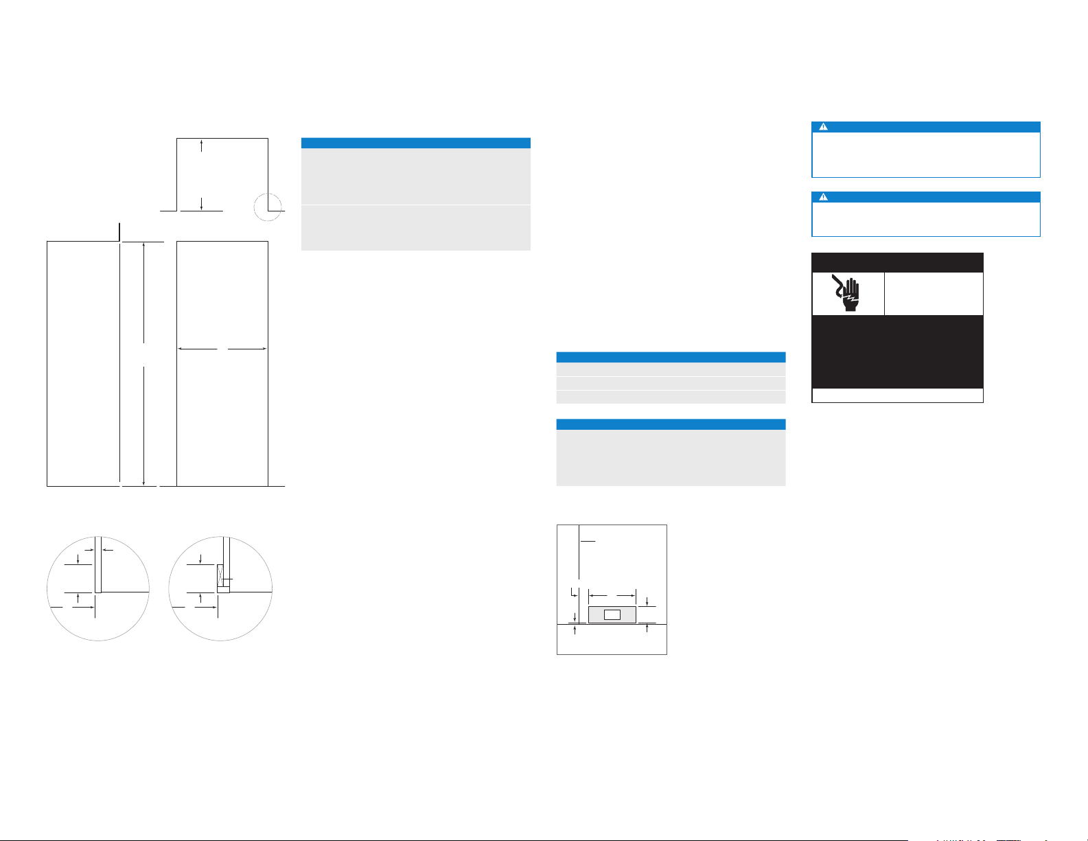
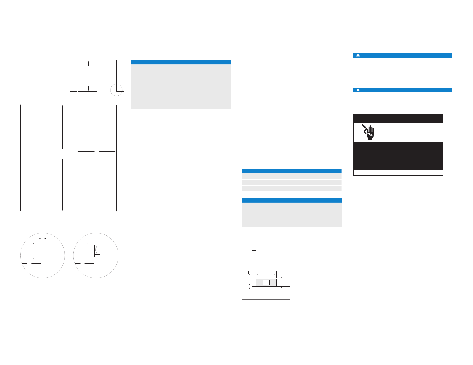
Opening Dimensions
INTEGRATED MODELS
OPENING
HEIGHT
VIEW
Electrical
Installation must comply with all applicable electrical codes
OPENING DIMENSIONS
635 mm
OPENING
DEPTH
654 mm
FOR OUTDOOR
MODEL
TOP VIEW
COLUMN AND TALL W H
457 mm Column 457 mm 2134 mm
610 mm Column 610 mm 2134 mm
762 mm Column and Tall 762 mm 2134 mm
914 mm Column and Tall 914 mm 2134 mm
DRAWER W H
610 mm Drawer 610 mm 876 mm
762 mm Drawer 762 mm 876 mm
914 mm Drawer 914 mm 876 mm
The depth of each wine storage model is 610 mm. Allow for
panel thickness when planning the nished opening depth.
A minimum 89 mm nished return is required on all sides of
the opening—114 mm for outdoor model. Framed cabinets
will require additional nished ller material behind the face
frame for a proper installation. Refer to the illustration.
H
W
OPENING WIDTH
DUAL INSTALLATION
When installing two units side by side in a dual installation, the opening width is the width of the two units added
together. A dual installation kit will be required for this instal-
and be properly grounded (earthed).
The electrical supply must be located within the shaded
area shown in the illustration and chart below. A separate
circuit, servicing only this appliance is required. Model
ICBID-24RO is designed and safe for use in outdoor
applications.
IMPORTANT NOTE: For indoor models, a ground fault circuit
interrupter (GFCI) is not recommended and may cause interruption of operation.
For the outdoor model, a ground fault circuit interrupter
(GFCI) is required to reduce the risk of electrical shock.
This appliance is equipped with an appliance inlet type
device. The appliance inlet is located at the bottom rear of
the appliance. When replacing the power cord verify the
replacement cord is rated HO5VV-F3G1.0 or equivalent to
ensure safe operation.
ELECTRICAL REQUIREMENTS
Power Supply 220-240 V AC, 50/60 Hz
Circuit Breaker 10 amp
Receptacle grounding-type (earthed)
lation. If a dual installation kit is not specied, a minimum
51 mm ller strip is required between units.
Dual installation kits are available through an authorized
Sub-Zero dealer.
FRONT VIEW
—
ELECTRICAL SUPPLY LOCATION
WIDTH A
457 mm Models 152 mm
610 mm Models 241 mm
762 mm Models 318 mm
914 mm Models 394 mm
CAUTION
The outlet must be checked by a qualied electrician to
be sure that it is wired with the correct polarity. Verify
that the outlet is properly grounded (earthed).
WARNING
Do not use an extension cord, two-prong adapter or
remove the power cord ground prong.
Electrical
Shock
Hazard
Plug power cord directly into a properly
grounded (earthed) outlet.
Do not defeat the grounding (earthing)
nature of the plug.
Do not use adapter or extension cord.
Failure to follow these instructions could
cause serious injury or death.
See installation instructions
19
mm
TYPICAL
89 mm
FINISHED
RETURN*
W W
FRAMELESS CABINETRY
89 mm
FINISHED
RETURN*
FILLER
FRAMED CABINETRY
LEFT SIDE
OF OPENING
114 mm
A
E
FLOOR
6 mm
FRONT VIEW
Electrical supply location
108
mm
subzero.com | 3
Page 4

SITE PREPARATION
TOP VIEW
BACK WALL
13 mm
A
WATER
LINE
152
mm
RIGHT
SIDE OF
OPENING
Plumbing
WARNING
Connect to potable water supply only.
Installation must comply with all applicable plumbing codes.
The water supply line should be located within the shaded
area shown in the illustrations below. The water supply line
should be connected to the house supply with an easily
accessible shut-off valve. Do not use self-piercing valves.
The water supply line must be ush to the oor and not
interfere with installation of the anti-tip bracket.
An in-line lter is required for models with an ice maker or
water dispenser when water conditions have a high sediment content.
A reverse osmosis system can be used provided there
is constant water pressure of 2.4–8.3 bar supplied to the
unit at all times. A copper line is not recommended for this
application.
PLUMBING REQUIREMENTS
Water Supply Line
Water Pressure 2.4–8.3 bar
Excess Water Line for Connection .9 m
WATER SUPPLY LOCATION
WIDTH A
457 mm Models 76 mm
610 mm Models 140 mm
762 mm Models 152 mm
914 mm Models 229 mm
1
/4" OD copper, braided
stainless steel or PEX tubing
Preparation
WARNING
To avoid a hazard due to instability of the appliance, it
must be xed in accordance with the instructions.
Uncrate the unit and inspect for damage. Remove the wood
base and discard shipping bolts and brackets. Remove and
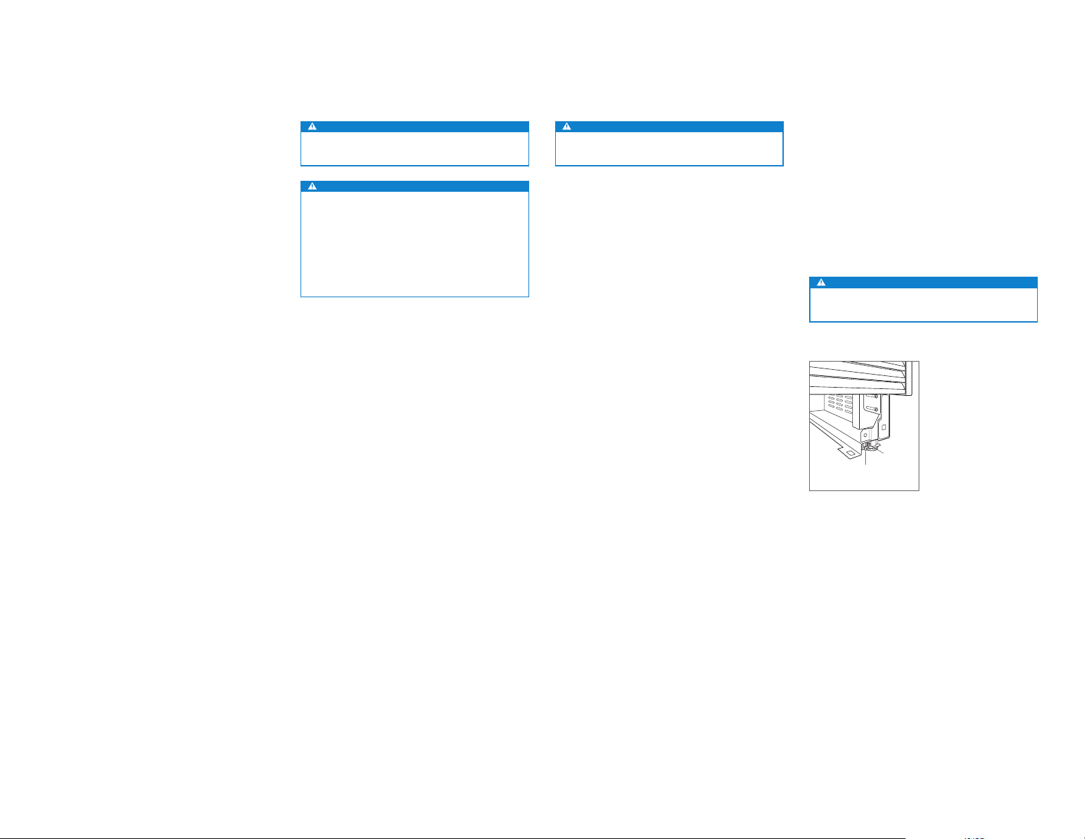
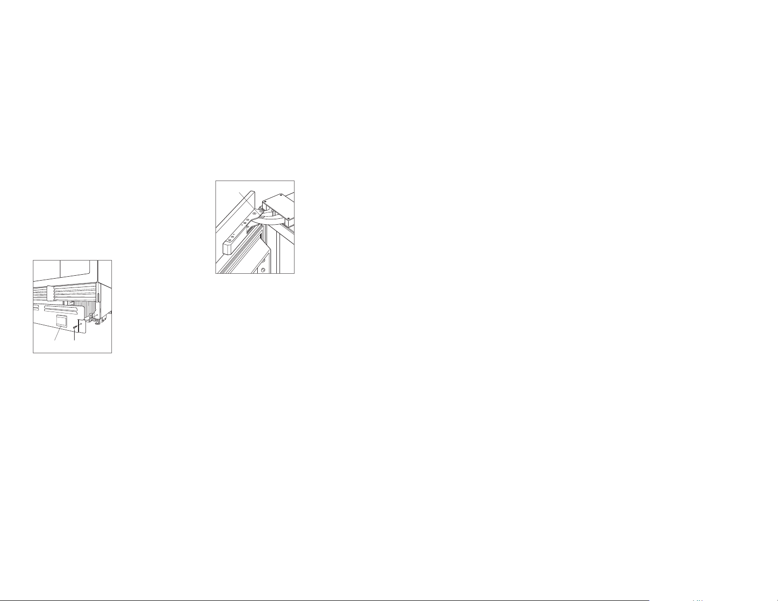
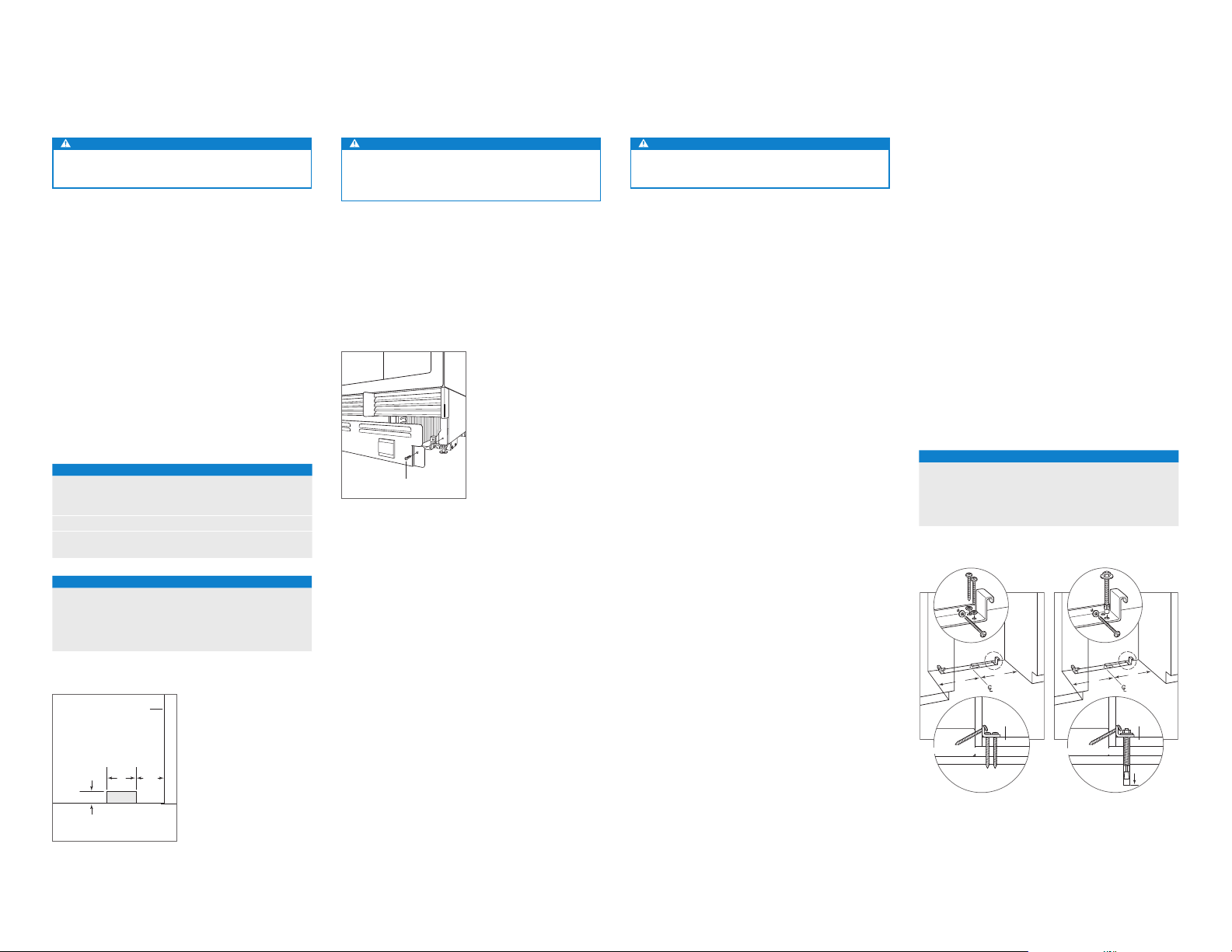
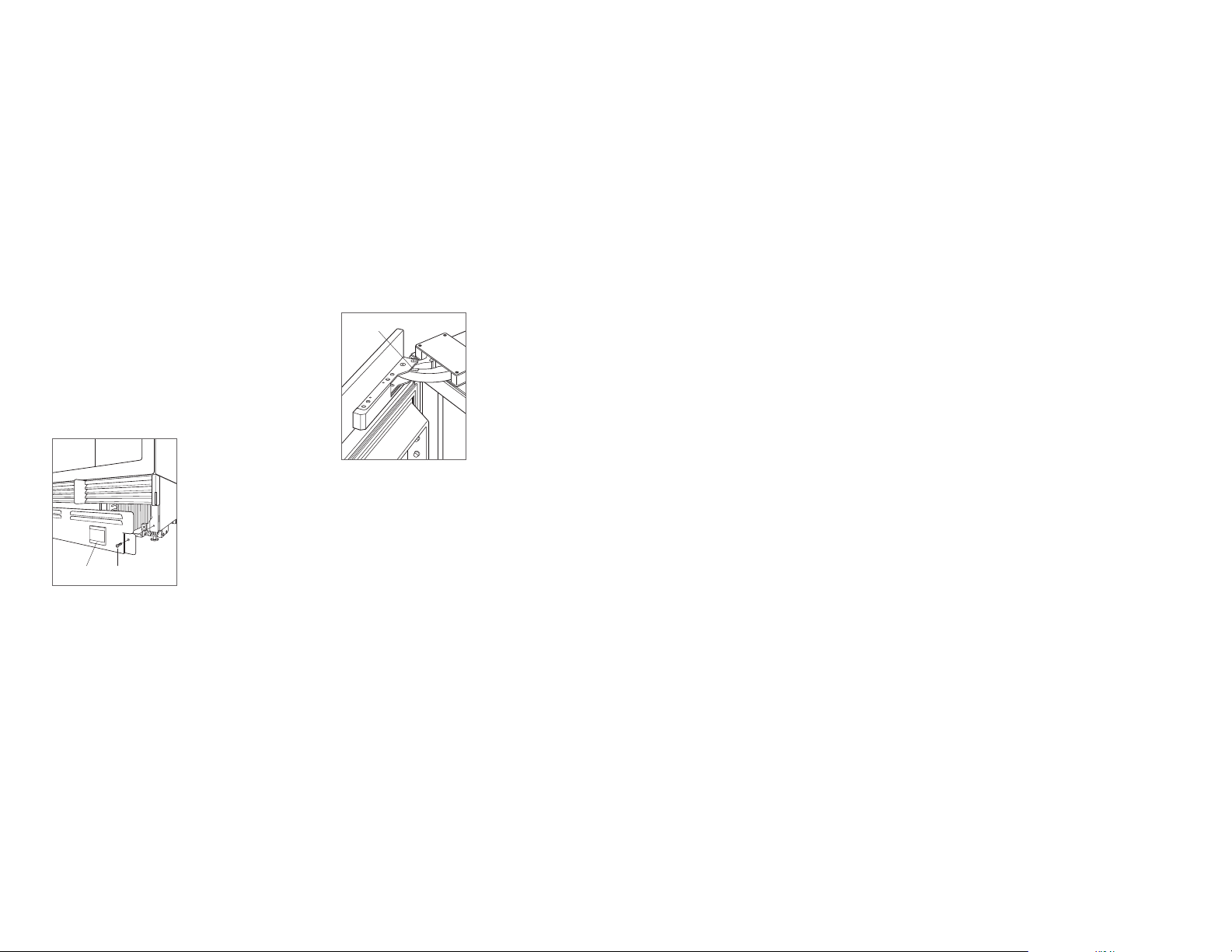
recycle packing materials. Do not discard the kickplate, antitip bracket and hardware.
Remove the kickplate by extracting the two mounting
screws. Refer to the illustration below.
SCREW
Kickplate removal
Anti-Tip Bracket
WARNING
To prevent the unit from tipping forward, the anti-tip
bracket must be installed.
The back of the anti-tip bracket must be installed 610 mm
from the front of the unit (without panels).
Use all anti-tip bracket hardware as instructed for wood or
concrete oors.
IMPORTANT NOTE: For wood or concrete oor applications,
if the #12 screws do not hit a wall stud or wall plate, use the
#8 screws and #12 washers with the wall anchors.
IMPORTANT NOTE: In some installations the subooring or
nished oor may necessitate angling the screws used to
fasten the anti-tip bracket to the back wall.
WOOD FLOOR APPLICATION
After properly locating the anti-tip bracket in the opening,
drill pilot holes 5 mm diameter maximum in the wall studs or
wall plate. Use the #12 screws and washers to secure the
brackets. Verify the screws penetrate through the ooring
material and into wall studs or wall plate a minimum of 19
mm. Refer to the illustration and chart below.
CONCRETE FLOOR APPLICATION
After properly locating the anti-tip bracket in the opening,
drill pilot holes 5 mm diameter maximum in the wall studs
or wall plate. Drill 10 mm diameter holes into the concrete a
minimum of 38 mm deep. Use the #12 screws and washers
to secure the brackets to the wall, and use the
3
/8" wedge
anchors to secure the brackets to the oor. Verify the screws
penetrate wall studs or wall plate a minimum of 19 mm.
Refer to the illustration and chart below.
ANTI-TIP BRACKET PLACEMENT
WIDTH A
457 mm Models 229 mm
610 mm Models 305 mm
762 mm Models 318 mm
914 mm Models 457 mm
A
WALL PLATE
SUBFLOORING
Wood oor
A
WOOD FLOOR
FINISHED
FLOORING
WALL PLATE
SUBFLOORING
Concrete oor
RIGHT SIDE
OF OPENING
A
152
FLOOR
mm
76 mm
FRONT VIEW
Water supply location
4 | English subzero.com
A
CONCRETE
FLOOR
A
FINISHED
FLOORING
38 mm
min
Page 5
SITE PREPARATION
INSTALLATION
Anti-Tip Bracket
CONCRETE WEDGE ANCHOR INSTALLATION:
1 Drill a 10 mm diameter hole any depth exceeding the
minimum embedment. Clean the hole or drill additional
depth to accommodate drill nes.
2 Assemble the washer and nut ush with the end of
anchor to protect threads. Drive the anchor through the
material to be fastened until the washer is ush with the
surface material.
3 Expand the anchor by tightening the nut 3–5 turns past
hand-tight position or to 34 newton-meters of torque.
WARNING
Verify there are no electrical wires or plumbing in the
area which the screws could penetrate.
CAUTION
Always wear safety glasses and use other necessary protective devices or apparel when installing or
working with anchors.
Anchors are not recommended for use in lightweight
masonry material such as block or brick, or for use in
new concrete which has not had sufcient time to cure.
The use of core drills is not recommended to drill holes
for the anchors.
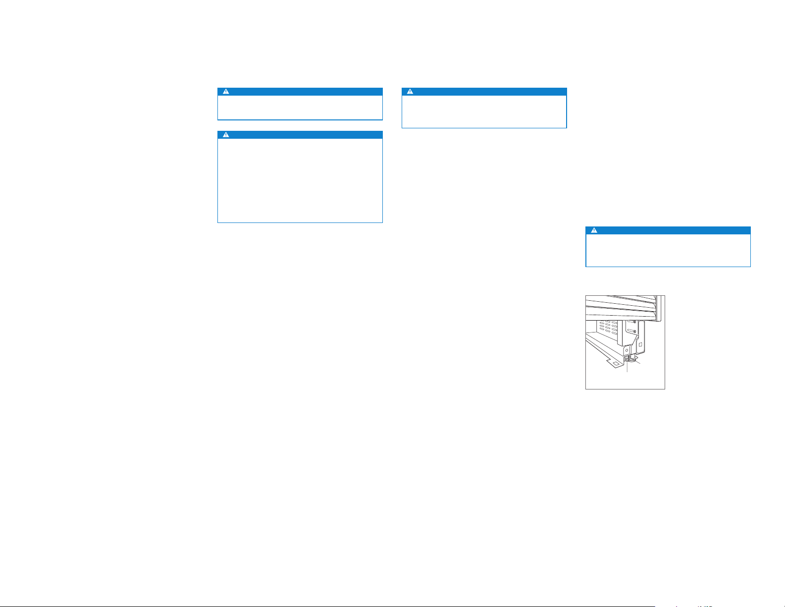
Placement
CAUTION
Before moving the unit into position, secure the door/
drawers closed and protect any nished ooring.
Use an appliance dolly to move the unit near the opening.
The front leveling legs are extended below the front rollers to
improve stability during placement. Once the unit is placed
in front of the opening, completely retract the front leveling
legs to allow the unit to be rolled into position. Front and
rear leveling legs can be adjusted from the front once the
unit is positioned.
If the unit has been on its back or side, it must stand upright
for a minimum of 24 hours before connecting power.
Plug the power cord into the grounded outlet and roll the
unit into position. Verify the anti-tip bracket is properly
engaged.
Alignment
LEVELING
Once the unit is in position, height adjustment can be made
from the front. Using a Phillips drive, turn clockwise to raise
the unit or counterclockwise to lower. Use the lowest torque
setting when using a power drill. Do not turn the leveling
legs by hand. Refer to the illustrations below.
When the unit is properly leveled, door/drawer adjustments
are less likely to be necessary.
IMPORTANT NOTE: Level the unit to the oor, not sur-
rounding cabinetry. This could affect the operation of the
unit, such as door closing.
WARNING
To reduce the possibility of the unit tipping forward,
the front leveling legs must be in contact with the oor.
FRONT
ADJUSTMENT
REAR
ADJUSTMENT
Leveling
subzero.com | 5
Page 6
PANELSINSTALLATION
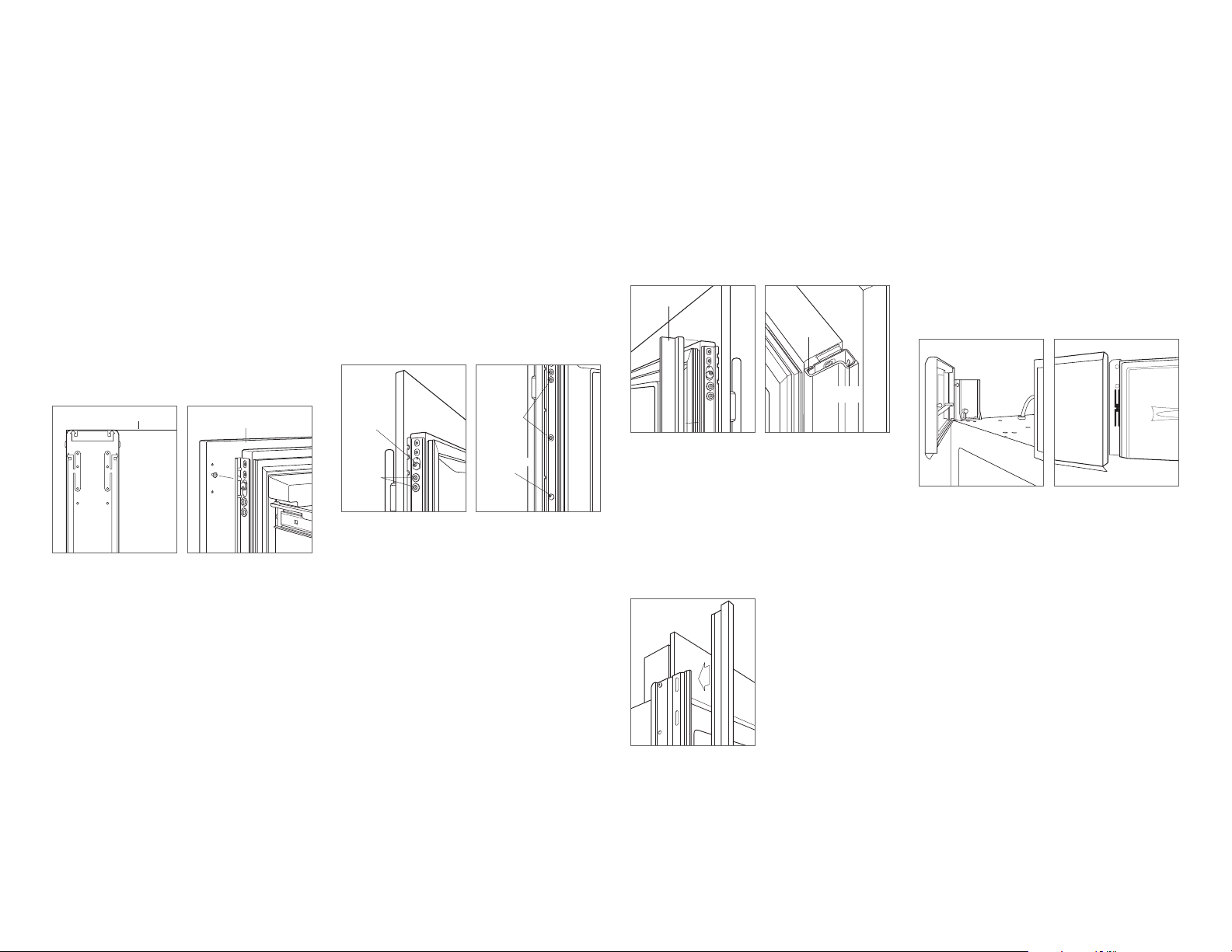
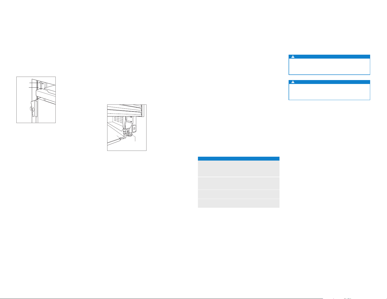
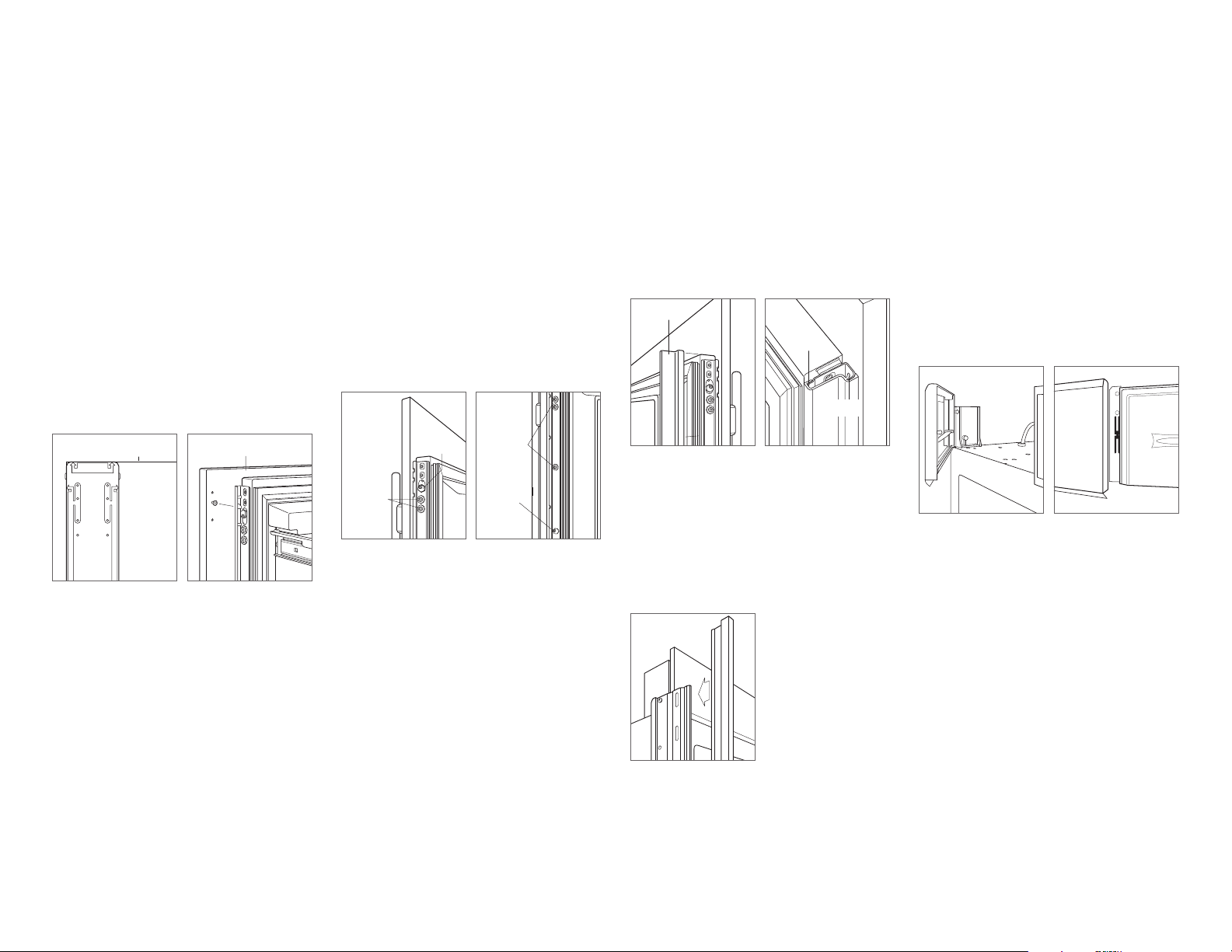
Alignment
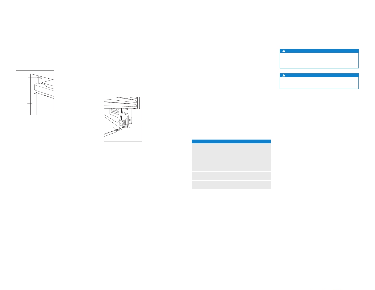
ANCHORING
Adjust the depth of the unit to t ush with surrounding
cabinetry. Once aligned, verify doors and drawers open
properly, then install screws in each side trim.
SCREW
SIDE TRIM
CABINETRY
FACE
FRAME
PANEL
THICKNESS
Anchoring
FRONT OF
UNIT
Water Line
Purge the water line prior to nal connection to the unit. This
will remove any debris that may be present in the tubing
from installing the new water line. Connect the plastic tubing
from the unit to the house water supply line with the tting
connection kit provided. Check all water line ttings for
leaks.
Locate the water line in the notch as shown in the illustration
below.
IMPORTANT NOTE: Water lines can not be exposed to
freezing temperatures.
NOTCH
WATER LINE
CONNECTION
Water line.
Stainless Steel Panels
The outdoor model requires the use of Sub-Zero stainless
steel outdoor accessory panels. Stainless steel panels are
available through an authorized Sub-Zero dealer.
The thickness of indoor stainless steel panels is 19 mm
and outdoor stainless steel panels are 38 mm. The depth of
each integrated model is 610 mm. Allow for panel thickness
when planning the nished opening depth.
3 mm reveals are typical, however, the reveal between the
upper and lower outdoor stainless steel panels is 6 mm to
accommodate the lock.
Custom Panels
For integrated models, custom door panels and handle
hardware must be installed.
The thickness of the custom panel can vary. A minimum
16 mm thick panel is required, but the thickness can be
increased provided it does not exceed the maximum panel
weight indicated in the chart below. The depth of each
integrated model is 610 mm. Allow for panel thickness when
planning the nished opening depth.
PANEL REQUIREMENTS
COLUMN MAX WEIGHT
457 mm Models 20 kg
610 mm Models 27 kg
762 / 914 mm Models 34 kg
TALL (DOOR) MAX WEIGHT
762 mm Models 22 kg
914 mm Models 27 kg
DRAWER MAX WEIGHT
All Drawer Panels 7 kg
PANEL THICKNESS MINIMUM
All Panels 16
Reveals between panels can vary, 3 mm reveals are typical.
CAUTION
When installing a panel thicker than 25 mm, the 90°
stop may be required to prevent damage to the unit
and adjacent cabinetry.
CAUTION
As reveals between cabinetry and the unit decrease,
severe nger pinching can occur while door is closing.
Finish all sides of custom panels. They will be visible when
the door is open.
D-style handles are recommended. Stainless steel tubular
and pro handles are avail able through an authorized
Sub-Zero dealer. Door handles must be located near the
edge of the panel opposite the hinge and should be centered top to bottom. Drawer handles must be located near
the top edge of each panel.
6 | English subzero.com
Page 7
PANELS
EDGE OF DOOR PANEL
EDGE OF DOOR PANEL
PANEL INSTALLATION
Custom Panels
DOOR PANEL HEIGHT
The height of the custom door panel can extend beyond the
typical panel height, provided it does not exceed the weight
limit. Refer to the illustration below.
45
mm
3 mm
DOOR
PANEL
2134
mm
HINGE
Upper valance (column and tall models)—side view
A DECORATIVE VALANCE
CANNOT EXTEND
BEYOND THIS PLANE
610 mm
TO BACK OF UNIT
TOE KICK CLEARANCE (EXCLUDES OUTDOOR MODEL)
The height of the toe kick area can extend beyond the
typical toe kick height, provided it does not exceed the
dimensions in the illustration below. Toe kick heights from
51 mm to 98 mm require a reduced toe kick accessory
available through an authorized
Sub-Zero dealer.
HINGE**
DOOR
PANEL
51 mm*
TO
152 mm
FROM
FLOOR
*51 mm to 98 mm requires sales accessory.
**Column models only
Toe kick—side view
VENTED
LOUVERS
610 mm
TO BACK OF UNIT
29 mm
MAX
TOE KICK
ADJUSTMENT
A DECORATIVE TOE KICK
CANNOT EXTEND
BEYOND THIS PLANE
Panel Installation
DOOR PANEL INSTALLATION
Typical panel dimensions are based on a 2134 mm nished
height with 3 mm reveals. Template placement must be
adjusted for panels exceeding typical dimensions.
For tall models, the door panel should be installed rst,
followed by the upper then lower drawer panel.
Place the panel face down on a protected work surface.
Position the template ush with the top and sides of the
panel. Verify the correct side of the template is being used,
then mark and drill holes. Refer to the illustration below.
For tall models, align the notch in the template with the
bottom of the door panel, then mark and drill holes. Refer to
the illustration below.
TOP OF DOOR PANEL
TOP OF
DOOR PANEL
84" APPLICATION
83 7/8" ACTUAL
DOOR PANEL
BOTTOM OF
USE TABS FOR HINGE
SIDE PANEL EDGE ON
DUAL INSTALLATION
Door panel template—top Door panel template—bottom
(tall models only)
BOTTOM OF
DOOR PANEL
DUAL INSTALLATION
SIDE PANEL EDGE ON
USE TABS FOR HINGE
BOTTOM OF
DOOR PANEL
83 7/8" ACTUAL
84" APPLICATION
DOOR PANEL
TOP OF
Use a Torx drive to partially insert a #8 x 13 mm screw into
the second hole from the top on each side of the panel. The
screws should be approximately 4 mm proud of the panel
and will support the weight of the panel during installation.
Align the support screws on the back of the panel with the
slotted holes on both door mounting brackets. Opening
the door slightly may help with alignment. Once the panel
is supported by the screws, partially insert a #8 x 13 mm
screw into the second hole from the bottom on each side of
the panel, but do not tighten.
CAUTION
As the reveal between cabinets and the unit decreases,
the potential exists for severe nger pinching if ngers
are placed in the opening when the door is closing.
BACK OF
DOOR PANEL
Door panel mounting
subzero.com | 7
Page 8
PANEL INSTALLATION
LEFT EDGE OF DRAWER PANEL
INSTALLATION
Panel Installation
DRAWER PANEL INSTALLATION
Place the panel face down on a protected work surface.
Position the template ush with the top and sides of the
panel. Verify the correct side of the template is being used,
then mark and drill holes. Refer to the illustration below.
Use a Torx drive to partially insert a #8 x 13 mm screw into
the second hole from the top on each side of the panel. The
screws should be approximately 4 mm proud of the panel
and will support the weight of the panel during installation.
Align the support screws on the back of the panel with the
slotted holes on both drawer mounting brackets. Refer
to the illustration below. Opening the drawer slightly may
help with alignment. Once the panel is supported by the
screws, partially insert a #8 x 13 mm screw into the second
hole from the bottom on each side of the panel, but do not
tighten.
TOP OF DRAWER PANEL
TOP OF
DRAWER PANEL
TOP HOLES
FOR UPPER
AND LOWER
DRAWERS
WER PANEL
Drawer panel template—top Drawer panel mounting
BACK OF
DRAWER PANEL
PANEL ADJUSTMENT
Close the door and/or drawers, now adjustments can be
made to align panels and reveals.
For side-to-side adjustment, move panels side to side, then
install and tighten all mounting screws.
For up-and-down and in-and-out adjustments, slightly
loosen the bracket screws. Depending on the level of
adjustment required, it may be helpful to loosen all of the
bracket screws which will allow for maximum adjustment.
Once the bracket screws are loosened, use a wrench to
rotate the cams to make adjustments. After adjustments
have been made, tighten all bracket screws. Refer to the
illustrations below.
IN-AND-OUT
CAM
BRACKET
SCREWS
In-and-out adjustment
BRACKET
SCREWS
UP-AND-DOWN
CAM
Up-and-down adjustment
Completion
DOOR TRIM INSTALLATION
After panels have been adjusted, install the decorative side
trim to the door/drawers. To install, start at the top and
align the trim with the front and rear anges on the bracket,
then snap into place by pushing the trim toward the back
of the panel. Once the top is secure, continue the installation downward until the remaining trim is completely secure.
Refer to the illustrations below.
DOOR TRIM
FRONT
FLANGE
REAR
FLANGE
Door trim
SIDE TRIM INSTALLATION
Install the decorative trim strip to the handle side of tall
and column models. The side trim snaps over the bracket
attached to the handle side of the unit. Refer to the illustration below.
Bracket anges
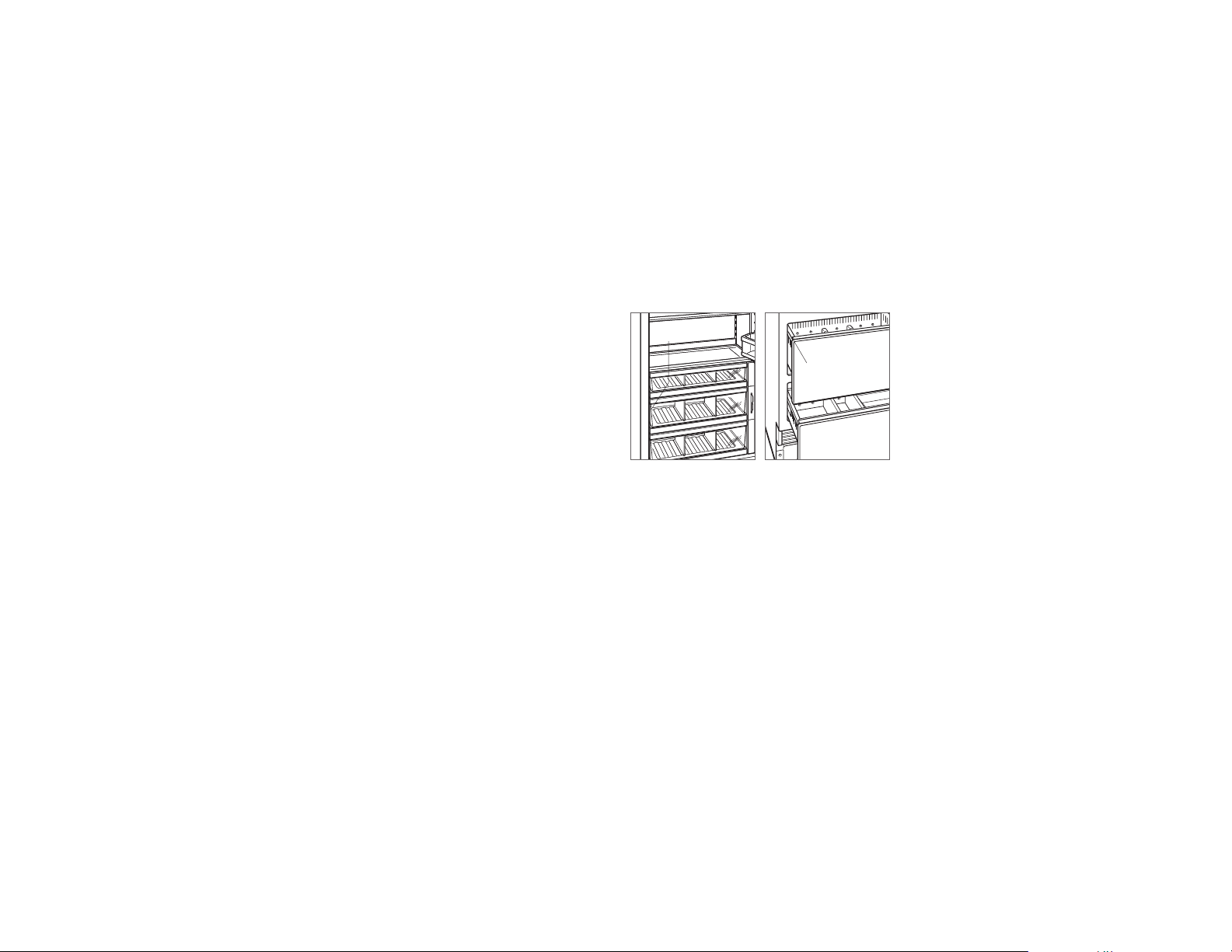
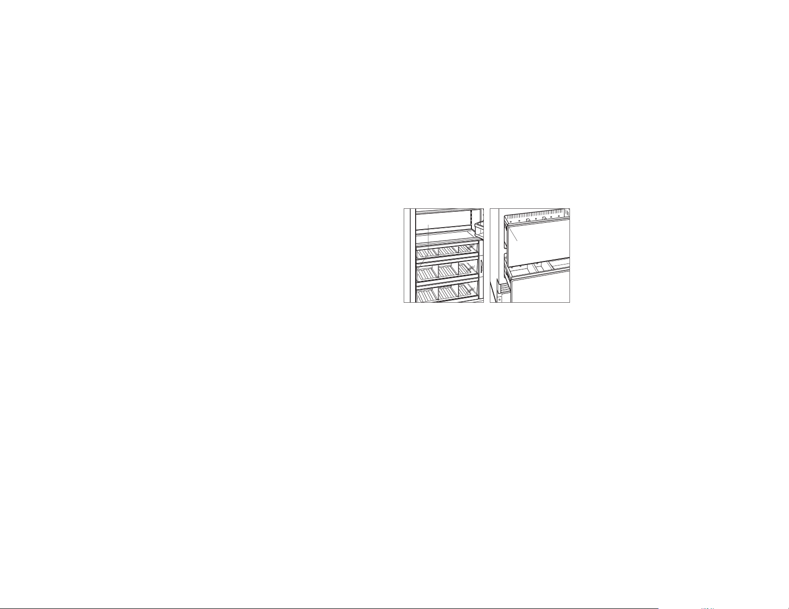
TOP TRIM INSTALLATION
Identify the top trim strips by the notch on one end at the
bottom; this trim strip ts on the hinge side of the unit.
Insert the outer end of each trim strip behind the vertical
side trim. Engage the snap in the plastic side bracket and
slide the panel as far to the outside as possible. Refer to the
illustration below.
Rotate the inner end of each panel into the side ange of
the center shroud, next to the water lter access door. Press
on the trim strip to snap into place. Refer to the illustration
below.
Inner top trim
Outer top trim
Side trim
8 | English subzero.com
Page 9
INSTALLATION
Completion
KICKPLATE INSTALLATION
Position the kickplate and install using the two mounting
screws. Refer to the illustration below. Kickplate must
be removable for service. The oor cannot interfere with
removal.
For indoor models, a maximum 152 mm decorative kickplate can be attached to the factory-installed kickplate. The
two rows of vented louvers can be covered if the door panel
is a minimum 102 mm from nished oor. A decorative kickplate can not be attached to the outdoor model.
To install a decorative kickplate, remove paper backing from
the magnets and attach decorative kickplate to magnets.
Magnets may also be tacked into position to increase adhesion. Magnets will allow decorative kickplate to be removed,
if necessary.
Turn power on by touching ‘power’ on the control panel.
90° DOOR STOP
A 105° door stop is built into the hinges of tall and column
units. To limit the door to 90°, open the door slightly less
than 90°, then use a standard screwdriver blade to remove
the existing clips from each hinge. Locate the 90° clips from
inside the plastic bag containing product literature, then
insert the 90° clips onto each hinge. Refer to the illustration
below.
CLIP
90° door stop
SCREWMAGNET
Kickplate installation
Sub-Zero, Sub-Zero & Design, Sub-Zero & Snowake Design, Dual Refrigeration, The Living Kitchen, Great American Kitchens The Fine Art of Kitchen Design, Wolf, Wolf & Design, Wolf Gourmet, W & Design, red colored knobs, Cove, and Cove & Design, are registered trademarks and service marks of Sub-Zero Group, Inc. and its subsidiaries.
All other trademarks are property of their respective owners in the United States and other countries.
subzero.com | 9
Page 10
REFRIGERACIÓN INTEGRABLE
Índice
2 Refrigeración integrable
3 Medidas de la cavidad
3 Potencia
4 Fontanería
4 Preparación
4 Soporte antivuelco
5 Colocación
5 Alineación
6 Conducto de agua
6 Paneles
7 Instalación del panel
8 Comprobación
Nota importante:
Para garantizar que este producto se instala y funciona de
la forma más ecaz y segura posible, tenga en cuenta la
información que se destaca en esta guía:
Cuando aparece NOTA IMPORTANTE, se resalta información
que resulta especialmente importante.
PRECAUCIÓN indica una situación en la que se pueden
sufrir heridas leves o provocar daños al producto si no se
siguen las instrucciones.
AVISO indica peligro de que se produzcan heridas perso-
nales graves o incluso la muerte si no se siguen las precauciones especicadas.
Información sobre el producto
En la placa de datos del producto encontrará información
importante, incluyendo el modelo y el número de serie. En
los modelos de columna, la placa de datos está situada
en el interior del cajón intermedio, próxima a la guía del
cajón frente a la bisagra. En los modelos de gran altura y
con cajones, la placa de datos está situada en el interior
del armario, a la izquierda del cajón superior. Observe las
siguientes ilustraciones.
Si necesita recurrir a un servicio técnico, póngase en contacto con su distribuidor de Sub-Zero autorizado.
PLACA
DE DATOS
PLACA
DE DATOS
Modelos de columna
Modelos altos y con cajones
Herramientas y materiales
• Destornilladores: estándar, Phillips y Torx.
• Taladro.
• Brocas (se necesitarán brocas de mampostería para una
instalación determinada).
• Juego de llaves y llaves de vaso estándar.
• Niveles de 0,6 m y 1,2 m.
• Instrumento especial para cortar el tubo.
1
• Tubo de 0,9m de
trenzado o de PEX.
• Válvula de montaje.
• Material para proteger la casa, el suelo y los armarios de
cocina durante la instalación.
/4" de cobre OD, acero inoxidable
2 | Español subzero.com
Page 11
PREPARACIÓN DEL SITIO
*Los retornos acabados de 89 mm serán visibles y deberán acabarse para que coincidan
con los muebles 114 mm para el modelo para exterior.
VIST
Medidas de la cavidad
MODELOS INTEGRABLES
H
ALTURA DE
LA CAVIDAD
A LATERAL
635 mm
PROFUNDIDAD
DE LA CAVIDAD
654 mm
PARA EL MODELO
PARA EXTERIOR
VISTA SUPERIOR
W
ANCHURA DE LA CAVIDAD
VISTA FRONTAL
MEDIDAS DE LA CAVIDAD
COLUMNA Y ALTURA W H
457 mm Columna 457 mm 2134 mm
610 mm Columna 610 mm 2134 mm
762 mm Columna y altura 762 mm 2134 mm
914 mm Columna y altura 914 mm 2134 mm
CAJÓN W H
610 mm Cajón 610 mm 876 mm
762 mm Cajón 762 mm 876 mm
914 mm Cajón 914 mm 876 mm
La profundidad de los modelos conservadores de vino es
de 610mm. Tenga en cuenta el grosor del panel cuando
calcule la profundidad de la cavidad acabada. Se necesita
un retorno acabado de un mínimo de 89 mm en todos los
lados de la cavidad 114 mm para el modelo para exterior.
Para una correcta instalación, los armarios con marco
requerirán un material de relleno adicional detrás del marco
frontal. Consulte la ilustración.
INSTALACIÓN DOBLE
Si se instalan dos unidades contiguas en una instalación
doble, el ancho de la cavidad es la cavidad de las dos
unidades añadidas juntas. Para esta instalación se necesita
un kit de instalación doble. Si no se especica el kit de
instalación doble, será necesario utilizar un embellecedor
de un mínimo de 51 mm entre las unidades.
Podrá encontrar los kits de instalación doble en un
distribuidor de Sub-Zero autorizado.
Potencia
La instalación debe cumplir con todas las normativas eléctricas
aplicables y debe estar correctamente conectada a tierra.
La toma eléctrica debe situarse en el área sombreada en la
ilustración y la tabla que se incluyen a continuación. Se necesita
un circuito independiente para esta unidad. El Modelo ICBID24RO está diseñado para su uso en condiciones de seguridad
en el exterior.
NOTA IMPORTANTE: Para modelos instalados en el interior, no
se recomienda utilizar un interruptor de circuito de fallos de
toma de tierra (GFCI), ya que puede interrumpir el funcionamiento de la unidad.
Para el modelo instalado en el exterior, es necesario un interruptor de circuito de toma a tierra para reducir el riesgo de
cortocircuitos.
El aparato está equipado con un dispositivo de entrada. La
entrada del aparato se encuentra en la parte inferior trasera
del dispositivo. Para cambiar el cable eléctrico es necesario
comprobar que el cable nuevo cuente con clasicación
HO5VV-F3G1.0 o una clasicación equivalente que garantice
el funcionamiento seguro.
REQUISITOS ELÉCTRICOS
Alimentación eléctrica 220-240 V CA, 50/60 Hz
Magnetotérmico 10 amperios
Enchufe con toma de tierra
UBICACIÓN DE LA ALIMENTACIÓN ELÉCTRICA
ANCHURA A
Modelos de 457mm 152mm
Modelos de 610mm 241mm
Modelos de 762mm 318mm
Modelos de 914mm 394mm
PRECAUCIÓN
La toma de corriente debe ser revisada por un electricista
cualicado para comprobar que la conexión se ha realizado con la polaridad correcta. Compruebe que la toma
de corriente está conectada a tierra de manera correcta.
AVISO
No utilice alargadores ni adaptadores, ni quite la clavija
de toma a tierra del cable eléctrico.
Peligro de
descarga
eléctrica
Enchufe el cable eléctrico directamente en una toma
con conexión a tierra.
No manipule la conexión a tierra del enchufe.
No utilice adaptadores ni alargadores.
Si no sigue estas instrucciones, existe riesgo de que
se produzcan heridas graves o incluso la muerte.
Ver instrucciones de instalación
19
mm
89 mm
RETORNO
ACABADO*
W W
MOBILIARIO SIN MARCO
TÍPICO
89 mm
RETORNO
ACABADO*
MOBILIARIO CON MARCO
RELLENO
LADO IZQUIERDO
DE LA CAVIDAD
114 mm
A
108
E
mm
SUELO
6 mm
VISTA FRONTAL
Ubicación de la alimentación
eléctrica
subzero.com | 3
Page 12
PREPARACIÓN DEL SITIO
VISTA SUPERIOR
PARED TRASERA
13 mm
A
CONDUCTO
DE AGUA
152
mm
LADO
DERECHO
DE LA
CAVIDAD
Fontanería
AVISO
Este aparato debe conectarse única y exclusivamente
a una toma de agua potable.
La instalación debe cumplir con toda la normativa local
aplicable en materia de fontanería.
La toma de agua puede situarse en el área sombreada de
las siguientes ilustraciones. El conducto de abastecimiento
de agua se debe conectar al suministro de la casa con
una válvula de cierre de fácil acceso. No utilice conexiones
auto-perforantes. El conducto del agua debe empotrarse
en el suelo para que no interera en la instalación de los
soportes antivuelco.
En los modelos con fabricador de cubitos de hielo o dispensador de agua, es necesario un ltro en la toma para que
no afecten al aparato los sedimentos que, en ocasiones, el
agua puede arrastrar.
Es posible utilizar un sistema de ósmosis invertido, siempre
y cuando la presión de agua que llegue a la unidad se
mantenga de forma constante entre 2,4 bar y 8,3 bar. No se
recomienda utilizar tubos de cobre para esta aplicación.
REQUISITOS DE FONTANERÍA
Conducto de abastecimiento de agua Tubo de 1/4" de cobre
Presión del agua 2,4–8,3 bares
Conducto de agua sobrante para
conexión
OD, acero inoxidable
trenzado o de PEX
0,9 m
Preparación
AVISO
Para evitar el peligro que puede ocasionar la inestabilidad del aparato, este debe jarse siguiendo las
instrucciones.
Desembale la unidad y compruebe si tiene algún daño o
desperfecto. Retire la base de madera y extraiga todos los
tornillos y soportes del paquete. Quite y recicle los materiales de embalaje. No tire el zócalo, el soporte antivuelco ni
las piezas de montaje.
Retire el zócalo extrayendo los dos tornillos de montaje.
Consulte la siguiente ilustración.
TORNILLO
Extracción del zócalo
Soporte antivuelco
AVISO
Debe instalarse el soporte antivuelco para evitar que la
unidad se incline hacia adelante.
La parte trasera del soporte antivuelco debe instalarse a
610mm de la parte delantera de la unidad (sin paneles).
Utilice todas las piezas del soporte antivuelco tal y como
se indica en las instrucciones para suelos de madera o de
hormigón.
NOTA IMPORTANTE: para aplicaciones en madera o en un
suelo determinado, en caso de que los tornillos del n.º 12
no alcancen el montante o la placa de pared, utilice tornillos
del n.º 8 y arandelas del n.º 12 con los anclajes para pared.
NOTA IMPORTANTE: en algunas instalaciones es posible
que, debido al tipo de suelo o acabado de este, sea necesario colocar los tornillos inclinados para sujetar el soporte
antivuelco a la pared trasera.
APLICACIÓN EN SUELO DE MADERA
Tras colocar correctamente el soporte antivuelco en la
cavidad, perfore oricios guía de 5mm de diámetro como
máximo en los montantes de pared o en la placa de pared.
Utilice arandelas y tornillos del n.º 12 para jar los soportes.
Compruebe que los tornillos penetren en el material del
suelo y en los montantes de pared o en las placas un
mínimo de 19 mm. Consulte la ilustración y la tabla que se
incluyen a continuación.
APLICACIÓN EN SUELO DE HORMIGÓN
Tras colocar correctamente el soporte antivuelco en la
cavidad, perfore oricios guía de 5mm de diámetro como
máximo en los montantes de pared o en la placa de pared.
Realice oricios de 10 mm de diámetro en el hormigón con
una profundidad mínima de 38 mm. Utilice arandelas y tornillos del n.º 12 para jar los soportes a la pared, y anclajes
de expansión de
3
/8" (9,5 mm) para jar los soportes al
suelo. Compruebe que los tornillos penetren en los montantes de pared o en las placas un mínimo de 19 mm. Consulte la ilustración y la tabla que se incluyen a continuación.
COLOCACIÓN DEL SOPORTE ANTIVUELCO
ANCHURA A
Modelos de 457 mm 229 mm
Modelos de 610 mm 305 mm
Modelos de 762 mm 318 mm
Modelos de 914 mm 457 mm
UBICACIÓN DE LA TOMA DE AGUA
ANCHURA A
Modelos de 457 mm 76 mm
Modelos de 610 mm 140 mm
Modelos de 762 mm 152 mm
Modelos de 914 mm 229 mm
A
A
LADO DERECHO
DE LA CAVIDAD
PLACA DE PARED
TIPO DE SUELO
A
152
SUELO
mm
76 mm
VISTA FRONTAL
Ubicación de la toma de agua
4 | Español subzero.com
Suelo de madera
SUELO
ACABADO
SUELO DE MADERA
PLACA DE PARED
TIPO DE SUELO
Suelo de hormigón
A
SUELO DE
HORMIGÓN
A
SUELO
ACABADO
38 mm
min
Page 13
PREPARACIÓN DEL SITIO
INSTALACIÓN
Soporte antivuelco
INSTALACIÓN DE ANCLAJES DE EXPANSIÓN PARA
HORMIGÓN:
1 Haga un agujero de 10 mm de diámetro con una profun-
didad superior al incrustado mínimo. Limpie el oricio o
continúe taladrando para hacer que el oricio sea más
profundo y quepan en él los residuos.
2 Coloque la arandela y la tuerca al nivel del extremo del
anclaje para proteger las roscas. Inserte el anclaje en el
material en el que debe atornillarse hasta que la arandela
quede nivelada con el material de la supercie.
3 Extienda el anclaje mediante una llave que sirva para
apretar la tuerca de 3 a 5 vueltas más de su posición
lograda con el apriete manual o hasta 34 Newton metros
de par.
AVISO
Compruebe que no haya cables eléctricos ni tuberías
en el área en la que se van a introducir los tornillos.
PRECAUCIÓN
Lleve siempre gafas de seguridad y utilice cualquier otro dispositivo o ropa de protección que sea
necesario cuando esté instalando o trabajando con
anclajes.
Se recomienda no utilizar los anclajes en material de
mampostería poco pesado, por ejemplo, bloques o
ladrillos, ni utilizarlo en hormigón fresco que no se haya
secado el tiempo suciente. No se recomienda utilizar
brocas huecas para hacer oricios para los anclajes.
Colocación
PRECAUCIÓN
Antes de desplazar la unidad para colocarla en su sitio,
asegúrese de que las puertas o cajones estén cerrados
y proteja el acabado del suelo.
Utilice una plataforma rodante para desplazar la unidad
hasta la cavidad. Las patas de nivelación delanteras sobresalen por debajo de las ruedas delanteras para mejorar la
estabilidad durante su colocación. Una vez colocada la
unidad en la parte delantera de la cavidad, repliegue completamente las patas de nivelación delanteras para permitir
que la unidad se pueda colocar en la posición adecuada. Las patas de nivelación delanteras y traseras
pueden ajustarse desde la parte delantera cuando la unidad
ya esté colocada.
Si la unidad ha estado boca abajo o sobre uno de los
lados, debe permanecer en posición vertical como mínimo
24horas antes de conectarla a la alimentación.
Enchufe el cable eléctrico en la toma de conexión a tierra y
coloque la unidad en la posición adecuada. Compruebe que
el soporte antivuelco esté bien jado.
Alineación
NIVELADO
Una vez colocada la unidad, el ajuste de la altura se puede
realizar desde la parte delantera. Con la ayuda de una punta
para tornillos de cabeza Phillips, gire en el sentido de las
agujas del reloj para levantar la unidad y en sentido contrario para bajarla. Utilice el ajuste de torsión más pequeño
si utiliza un taladro. No gire manualmente las patas de nivelación. Observe las siguientes ilustraciones.
Cuando la unidad esté correctamente nivelada, no será tan
necesario realizar los ajustes de las puertas o cajones.
NOTA IMPORTANTE: nivele la unidad con el suelo, y no con
los demás muebles, pues podría afectar al funcionamiento
de la unidad como, por ejemplo, impidiendo que la puerta
se cierre correctamente.
AVISO
Para evitar que la unidad vuelque hacia delante, las
patas de nivelación delanteras deben llegar hasta el
suelo.
Nivelado
AJUSTE
TRASERO
AJUSTE
DELANTERO
subzero.com | 5
Page 14
PANELSINSTALACIÓN
Alineación
ANCLAJE
Ajuste la profundidad de la unidad para que quede a ras
con los gabinetes circundantes. Una vez alineados, verique
que las puertas y los cajones se abran correctamente, luego
instale los tornillos en cada guarnecido lateral.
TORNILLO
BORDE
LATERAL
MARCO
DELANTERO
DEL
MUEBLE
Anclaje
PARTE
DELANTERA
DE LA UNIDAD
Conducto de agua
Purgue el conducto de agua antes de conectarlo a la
unidad. Esto hará que se elimine cualquier tipo de suciedad
que pueda haber en el tubo al instalar el nuevo conducto de
agua. Conecte el tubo de plástico de la unidad con la toma
de agua doméstica usando el equipo de conexión suministrado para su instalación. Compruebe si existe alguna fuga
de agua en las conexiones del conducto.
Coloque la línea de agua en la muesca como se muestra en
la siguiente ilustración.
NOTA IMPORTANTE: no se pueden exponer las tomas de
agua a temperaturas de congelación.
MUESCA
CONEXIÓN A LA
TOMA DE AGUA
Conducto de agua.
Paneles de acero inoxidable
El modelo para exterior requiere el uso de paneles accesorios para exterior de acero inoxidable de Sub-Zero. Podrá
encontrar los paneles de acero inoxidable en un distribuidor
de Sub-Zero autorizado.
El grosor de los paneles de acero inoxidable para interior es
de 19 mm y el de los paneles de acero inoxidable para exterior, de 38 mm. La profundidad de cada modelo integrado
es de 610 mm. Tenga en cuenta el grosor del panel cuando
calcule la profundidad de la cavidad acabada.
Los márgenes 3 mm son normales. Sin embargo, el margen
entre los paneles exteriores de acero inoxidable superior e
inferior es de 6 mm para poder encajar la cerradura.
Paneles a medida
En los modelos integrables, se deben instalar tiradores y
paneles de puerta a medida.
El grosor del panel a medida puede variar. Será necesario
un panel con un mínimo de 16mm de grosor, medida que
podrá aumentarse siempre y cuando no se supere el límite
de peso del panel indicado en la siguiente tabla. La profundidad de los modelos integrables es de 610mm. Tenga en
cuenta el grosor del panel cuando calcule la profundidad de
la cavidad acabada.
REQUISITOS DEL PANEL
COLUMNA PESO MÁX.
Modelos de 457 mm 20 kg
Modelos de 610 mm 27 kg
Modelos de 762/914mm 34 kg
ALTO (PUERTA) PESO MÁX.
Modelos de 762 mm 22 kg
Modelos de 914 mm 27 kg
CAJÓN PESO MÁX.
Todos los paneles de los cajones 7 kg
GROSOR DEL PANEL MÍNIMO
Todos los paneles 16
Los márgenes entre paneles pueden variar, los de 3mm son
los más corrientes.
PRECAUCIÓN
Si se instala un panel con un grosor de más de 25 mm,
puede que sea necesario un tope de 90º para evitar
que se dañe la unidad y los muebles circundantes.
PRECAUCIÓN
Cuanto menos separación se deje entre los muebles
y la unidad, más daño se puede hacer al pillarse los
dedos en el hueco al cerrar la puerta.
Realice el acabado de todos los lados de los paneles a
medida, pues son áreas que resultarán muy visibles al abrir
la puerta.
Se recomiendan los tiradores en D. Podrá encontrar tiradores tubulares y pro de acero inoxidable en un distribuidor
autorizado de Sub-Zero. Los tiradores de la puerta deben
colocarse cerca del borde del panel en el lado contrario a
la bisagra y centrados. Los tiradores de los cajones pueden
colocarse cerca del borde superior de cada panel.
6 | Español subzero.com
Page 15
PANELS
EDGE OF DOOR PANEL
EDGE OF DOOR PANEL
Paneles a medida
ALTURA DEL PANEL DE LA PUERTA
Es posible aumentar la altura del panel de la puerta a
medida por encima de la altura típica del panel, siempre
que no se supere el límite de peso. Consulte la siguiente
ilustración.
45
mm
3 mm
PANEL
DE LA
PUERTA
2134
mm
BISAGRA
Cenefa superior (modelos altos y de columna): vista lateral
LA CENEFA
DECORATIVA NO
PUEDE SOBRESALIR
DE ESTE PLANO
610 mm
A LA PARTE POSTERIOR
DE LA UNIDAD
ESPACIO PARA RODAPIÉ
(EXCLUIDO EL MODELO PARA EXTERIOR)
Es posible aumentar la altura de la zona de rodapié por
encima de la altura típica del rodapié, siempre que no se
superen las dimensiones de la siguiente ilustración.
Los
rodapiés con alturas de 51 a 98 mm requieren un accesorio
de rodapié reducido disponible en los distribuidores Sub-Zero
autorizados.
BISAGRA**
PANEL
DE PUERTA
DE
102 mm*
A
152 mm
DESDE
EL SUELO
*De 51 mm a 98 mm requiere accesorios de ventas.
**Únicamente modelos de columna
Rodapié: vista lateral
REJILLAS DE
VENTILACIÓN
610 mm
A LA PARTE
POSTERIOR
DE LA UNIDAD
29 mm
MÁX. PARA
AJUSTE
DEL RODAPIÉ
EL RODAPIÉ DECORATIVO
NO PUEDE SOBRESALIR
DE ESTE PLANO
Instalación del panel
INSTALACIÓN DEL PANEL DE LA PUERTA
Las medidas típicas del panel están calculadas con una
altura de 2 134mm una vez acabado con una separación
de 3 mm. Debe ajustarse la colocación de las plantillas en
los paneles que superen las medidas típicas.
En los modelos altos, el panel de la puerta debe instalarse
en primer lugar, seguido del panel superior de los cajones y,
a continuación, el inferior.
Coloque el panel boca abajo en una supercie de trabajo
protegida. Coloque la plantilla alineada con la parte superior
y los laterales del panel. Compruebe que está utilizando el
lateral adecuado de la plantilla y después marque y haga los
oricios. Consulte la siguiente ilustración.
En los modelos altos, debe alinear la muesca de la plantilla
con la parte inferior del panel de la puerta y después marcar
y hacer los oricios. Consulte la siguiente ilustración.
PARTE SUPERIOR DEL
PANEL DE LA PUERTA
TOP OF
DOOR PANEL
84" APPLICATION
83 7/8" ACTUAL
DOOR PANEL
BOTTOM OF
USE TABS FOR HINGE
SIDE PANEL EDGE ON
DUAL INSTALLATION
Plantilla del panel de la puerta:
parte superior
Plantilla del panel de la puerta:
parte inferior (solo modelos
altos)
BOTTOM OF
DOOR PANEL
DUAL INSTALLATION
SIDE PANEL EDGE ON
USE TABS FOR HINGE
83 7/8" ACTUAL
84" APPLICATION
DOOR PANEL
TOP OF
PARTE INFERIOR
DEL PANEL
DE LA PUERTA
Utilice una unidad Torx para insertar parcialmente un tornillo
#8 x 13 mm en el segundo agujero desde la parte superior de cada lado del panel. Los tornillos deben sobresalir
aproximadamente 4mm del panel y soportarán el peso del
panel durante la instalación.
Alinee los tornillos de soporte en la parte trasera del panel
con los oricios ranurados de los dos soportes de montaje
de la puerta. Abrir ligeramente la puerta le ayudará a realizar
la alineación. Cuando el panel se sostenga en los tornillos,
inserte parcialmente un tornillo n.º 8 x 13 en el segundo
agujero desde la parte inferior a cada lado del panel, pero
no los ajuste.
PRECAUCIÓN
Cuanta menos separación se deje entre los muebles y
la unidad, más posibilidades hay de que se pueda pillar
los dedos si se meten en el hueco al cerrar la puerta.
PARTE TRASERA DEL
PANEL DE LA PUERTA
Montaje del panel de la puerta
subzero.com | 7
Page 16
INSTALACIÓN DEL PANEL
LEFT EDGE OF DRAWER PANEL
INSTALACIÓN
Instalación del panel
INSTALACIÓN DE LOS PANELES DE LOS CAJONES
Coloque el panel boca abajo en una supercie de trabajo
protegida. Coloque la plantilla alineada con la parte superior
y los laterales del panel. Compruebe que está utilizando el
lateral adecuado de la plantilla y después marque y haga los
oricios. Consulte la siguiente ilustración.
Utilice una unidad Torx para insertar parcialmente un tornillo
#8 x 13 mm en el segundo agujero desde la parte superior de cada lado del panel. Los tornillos deben sobresalir
aproximadamente 4mm del panel y soportarán el peso del
panel durante la instalación.
Alinee los tornillos de soporte en la parte trasera del panel
con los oricios ranurados de los dos soportes de montaje
del cajón. Consulte la siguiente ilustración. Abrir ligeramente
el cajón le ayudará a realizar la alineación. Cuando el panel
se sostenga en los tornillos, inserte parcialmente un tornillo
n.º 8 x 13 en el segundo agujero desde la parte inferior a
cada lado del panel, pero no los ajuste.
PARTE SUPERIOR DEL
PANEL DEL CAJÓN
TOP OF
DRAWER PANEL
TOP HOLES
FOR UPPER
AND LOWER
DRAWERS
WER PANEL
Plantilla del panel del cajón:
parte superior
PARTE TRASERA DEL
PANEL DEL CAJÓN
Montaje del panel del cajón
AJUSTE DEL PANEL
Cierre la puerta y cajones para realizar los ajustes de alineación de los paneles y márgenes.
Para realizar un ajuste de lado a lado, mueva los paneles de
lado a lado y después instale y apriete todos los tornillos de
montaje.
Para realizar los ajustes hacia arriba y hacia abajo, hacia
dentro y hacia fuera, aoje ligeramente los tornillos del
soporte. Según el nivel de ajuste necesario, posiblemente resulte conveniente aojar todos los tornillos de los
soportes, ya que esto permitirá un ajuste máximo. Una
vez aojados los tornillos del soporte, gire las palancas
para realizar los ajustes. Después de realizar los ajustes,
apriete los tornillos del soporte. Observe las siguientes
ilustraciones.
LEVA HACIA
DENTRO Y
HACIA FUERA
TORNILLOS
DE SOPORTE
Ajuste hacia dentro y hacia
fuera
TORNILLOS
DE SOPORTE
LEVA HACIA
ARRIBA Y
HACIA ABAJO
Ajuste hacia arriba y hacia
abajo
Comprobación
INSTALACIÓN DE LOS BORDES DE LA PUERTA
Después de ajustar los paneles, instale el borde decorativo en
los laterales en las puertas o cajones. Para instalarlo, empiece
en la parte superior y alinee el borde con la parte superior
y trasera del soporte, y colóquelo en su lugar empujando
el borde hacia la parte posterior del panel. Cuando la parte
superior esté asegurada, continúe la instalación hacia abajo
hasta que el borde restante quede completamente asegurado.
Observe las siguientes ilustraciones.
BORDE DE
LA PUERTA
BORDE
FRONTAL
BORDE
TRASERO
Borde de la puerta
INSTALACIÓN DEL BORDE LATERAL
Instale la banda decorativa en el borde del lado del tirador
en los modelos altos y de columna. El borde lateral se
coloca sobre el soporte situado en el lado del tirador de la
unidad. Observe la siguiente ilustración.
Bordes del soporte
INSTALACIÓN DEL BORDE SUPERIOR
Identique las bandas de los bordes superiores con la
muesca en uno de los extremos inferiores; estas bandas
de los bordes coinciden con el lado de las bisagras de la
unidad.
Inserte el extremo exterior de cada una de las bandas de
los bordes detrás del borde lateral vertical. Ajuste el cierre
del soporte lateral de plástico y deslice el panel hacia afuera
todo lo que pueda. Consulte la siguiente ilustración.
Gire el extremo interior de cada panel hacia la placa lateral
del protector central, situado al lado de la puerta de acceso
del ltro de agua. Presione la banda del borde para colocarla en su lugar. Consulte la siguiente ilustración.
Borde superior interior
Borde superior exterior
Borde lateral
8 | Español subzero.com
Page 17
INSTALACIÓN
Comprobación
INSTALACIÓN DEL ZÓCALO
Coloque el zócalo e instálelo con dos tornillos de montaje.
Consulte la siguiente ilustración. El zócalo debe ser extraíble
para permitir sacarlo en caso de avería. El suelo no puede
ser un impedimento para llevar a cabo esta operación.
Para los modelos instalados en el interior, es posible añadir
un máximo de 152 mm de zócalo decorativo al zócalo
instalado de fábrica. Las dos las de rejillas de ventilación
pueden cubrirse si el panel de la puerta está a una distancia
mínima de 102 mm del acabado del suelo. No se puede
instalar un zócalo decorativo en el modelo para exterior.
Para instalar un zócalo decorativo, retire el papel de la
parte posterior de los imanes y una el zócalo decorativo a
los imanes. Los imanes también pueden colocarse en su
posición para mejorar la adhesión. Permitirán extraer el
zócalo decorativo en caso de que sea necesario.
Encienda la unidad pulsando el botón de encendido en el
panel de control.
TOPE DE PUERTA A 90°
Las bisagras de las puertas de las unidades altas y de
columna incorporan un tope de 105º. Para limitar la puerta
a 90º, abra la puerta un poco menos de 90º y después
utilice la hoja de un destornillador estándar para quitar las
sujeciones de cada bisagra. Saque las sujeciones de 90º
que se encuentran en el interior de la bolsa de plástico que
contiene las instrucciones del producto, y después inserte
las sujeciones de 90º en las bisagras. Consulte la siguiente
ilustración.
FIJADOR
Tope de puerta a 90°
TORNILLOIMÁN
Instalación del zócalo
Sub-Zero, Sub-Zero & Design, Sub-Zero & Snowake Design, Dual Refrigeration, The Living Kitchen, Great American Kitchens The Fine Art of Kitchen Design, Wolf, Wolf & Design, Wolf Gourmet, W & Design, los mandos de color rojo, Cove, and Cove & Design son marcas registradas y marcas de servicio de Sub-Zero Group, Inc. y sus liales.
Todas las demás marcas son propiedad de sus respectivos propietarios en los Estados Unidos y en otros países.
subzero.com | 9
Page 18
APPAREILS DE RÉFRIGÉRATION INTÉGRABLES
Table des matières
2 Appareils de réfrigération intégrables
3 Cotes d’encastrement
3 Électricité
4 Plomberie
4 Préparation
4 Support antibasculement
5 Emplacement
5 Alignement
6 Canalisation d’eau
6 Panneaux
7 Pose des panneaux
8 Dernières nitions
Remarque importante
Pour garantir une installation de ce produit aussi sûre et efcace que possible, veuillez faire particulièrement attention
aux mentions mises en évidence tout au long de ce guide,
notamment :
REMARQUE IMPORTANTE met l’accent sur un renseigne-
ment particulièrement important.
MISE EN GARDE signale un danger qui pourrait causer une
blessure mineure ou endommager le produit si vous ne
suivez pas les instructions.
AVERTISSEMENT signale un danger qui pourrait causer
des blessures graves voire fatales si vous ne prenez pas
certaines précautions.
Information concernant le produit
Les renseignements importants concernant le produit,
notamment la référence modèle et le numéro de série,
gurent sur la plaque des caractéristiques du produit. Pour
les modèles en colonne, la plaque des caractéristiques
du produit se trouve à l’intérieur du tiroir central près de la
glissière du tiroir, du côté opposé à la charnière. Pour les
modèles grande hauteur et à tiroirs, la plaque des caractéristiques du produit se trouve dans l’armoire à gauche du
tiroir supérieur. Reportez-vous aux illustrations ci-après.
S’il faut effectuer une réparation, adressez-vous à un revendeur Sub-Zero agréé.
PLAQUE DES
CARACTÉRISTIQUES
PLAQUE DES
CARACTÉRISTIQUES
Modèles colonne
Modèles grande hauteur et
à tiroirs
Outils et matériaux
• Tournevis—normaux, à pointe cruciforme et Torx.
• Perceuse électrique.
• Mèches (mèches de maçonnerie nécessaires pour
l’installation dans le béton).
• Jeu de clés et de douilles normales.
• Niveaux de 0,6 m et 1,2 m.
• Coupe-tube.
• Tube PEX, en acier inoxydable tressé ou en cuivre de
0,9m de long et de 6,35 mm de diamètre extérieur.
• Robinet-vanne.
• Matériel pour protéger la maison, le sol et son mobilier
pendant l’installation.
2 | Français subzero.com
Page 19

PRÉPARATION DE L’EMPLACEMENT
*Les replis finis de 89 mm sont visibles et doivent être finis pour être assortis aux autre
éléments de cuisine — 114 mm pour le modèle extérieur.
VUE LA
Cotes d’encastrement
MODÈLES INTÉGRABLES
H
HAUTEUR
D'OUVERTURE
TÉRALE
635 mm
PROFONDEUR
D'OUVERTURE
654 mm
POUR MODÈLE
EXTÉRIEUR
VUE EN PLAN
L
LARGEUR D'OUVERTURE
VUE DE FACE
COTES D’ENCASTREMENT
COLONNE ET GRANDE HAUTEUR L H
457 mm Colonne 457 mm 2134 mm
610 mm Colonne 610 mm 2134 mm
762 mm Colonne et Grande hauteur 762 mm 2134 mm
914 mm Colonne et Grande hauteur 914 mm 2134 mm
TIROIR L H
610 mm Tiroir 610 mm 876 mm
762 mm Tiroir 762 mm 876 mm
914 mm Tiroir 914 mm 876 mm
Chaque modèle de cave à vin mesure 610 mm de profondeur.
Tenez compte de l'épaisseur du panneau lorsque vous
préparez la profondeur d'ouverture nie. Un repli ni d'au
moins 89 mm est nécessaire tout autour de l'ouverture—
114 mm pour le modèle extérieur. Pour les meubles
avec encadrement, il faut également installer un ller ni
supplémentaire derrière l'encadrement de la façade pour
assurer une bonne installation. Reportez-vous à l'illustration.
INSTALLATION CONJOINTE
Lorsque vous installez deux appareils côte à côté en
installation double, la largeur de l'ouverture égale la somme
de la largeur des deux appareils. Il sera nécessaire d'avoir
un kit d'installation conjointe pour cette installation. Si aucun
kit d'installation conjointe n'est spécié, il est recommandé
d'utiliser un ller de 51 mm au moins entre les appareils.
Ces kits d'installation conjointe sont disponibles chez un
revendeur agréé Sub-Zero.
s
Électricité
L'installation doit se conformer à tous les codes électriques
applicables. Elle doit être correctement mise à la terre.
L’alimentation en électricité doit se trouver dans la zone
ombrée indiquée sur l’illustration et dans le tableau cidessous. Il est nécessaire d’avoir un circuit indépendant,
alimentant uniquement cet appareil ménager. Le modèle
ICBID-24RO est étudié pour être utilisé en toute sécurité à
l'extérieur.
REMARQUE IMPORTANTE : Pour le modèle intérieur, il n'est
pas recommandé d'avoir recours à un disjoncteur différentiel (GFCI) qui pourrait provoquer l'interruption du fonctionnement de l'appareil.
Pour le modèle extérieur, un disjoncteur différentiel (GFCI)
est requis pour minimiser le risque de choc électrique.
Cet appareil est pourvu d’un orice d’accès. L’orice
d’accès se trouve à l’arrière, en bas de l’appareil. Lorsque
vous remplacez le cordon électrique, vériez que le nouveau
cordon soit de catégorie HO5VV-F3G1.0 ou équivalente an
d’assurer un fonctionnement en toute sécurité.
CONFIGURATION ÉLECTRIQUE
Alimentation électrique 220-240 V c.a., 50/60 Hz
Disjoncteur 10 A
Prise type mise à la terre
EMPLACEMENT DE L’ALIMENTATION ÉLECTRIQUE
PORTE A
Modèles de 457 mm 152 mm
Modèles de 610 mm 241 mm
Modèles de 762 mm 318 mm
Modèles de 914 mm 394 mm
MISE EN GARDE
La prise doit être vériée par un électricien qualié.
Celui-ci doit s’assurer qu’elle est dotée de la polarité
adéquate. Assurez-vous que la prise est correctement
mise à la terre.
AVERTISSEMENT
N’utilisez pas de rallonge ni d’adaptateur à deux
broches. Ne retirez pas non plus la broche de mise à la
terre du cordon électrique.
Électricité
Danger de
choc électrique
Branchez directement le cordon électrique
dans une prise avec mise à la terre adéquate.
N’entravez pas la fonction de mise à la
terre du cordon électrique.
N’utilisez pas d’adaptateur ou de cordon
de rallonge.
Le non-respect de ces instructions pourrait
entraîner des blessures graves voire mortelles.
Voir les instructions d’installation
19
mm
TYPIQUE
89 mm
REPLI
FINI*
L L
MEUBLES SANS
MOULURE
89 mm
REPLI
FINI*
MEUBLES AVEC
CADRE
FILLER
CÔTÉ GAUCHE
DE L’OUVERTURE
114 mm
A
108
E
mm
SOL
6 mm
VUE DE FACE
Emplacement de l’alimentation
électrique
subzero.com | 3
Page 20

PRÉPARATION DE L’EMPLACEMENT
VUE EN PLAN
MUR ARRIÈRE
13 mm
A
CANALISATION
D’EAU
152
mm
CÔTÉ
DROIT DE
L’OUVERTURE
Plomberie
AVERTISSEMENT
Ne raccorder qu'à une alimentation en eau potable.
L’installation doit se conformer à tous les codes de plomberie applicables.
L’arrivée d’eau doit se trouver dans la zone ombrée indiquée
sur les illustrations ci-après. La lyre devra être branchée à
l’alimentation en eau de la maison avec un robinet d’arrêt
facile d’accès. N’utilisez pas de robinet auto-perceur. La
canalisation d’eau doit être à eur du plancher et ne doit
pas gêner l’installation du support antibasculement.
Un ltre est requis pour les modèles avec fabrique de glaçons ou distributeur d’eau si l’eau a une teneur importante
en sédiments.
Un système d’osmose inversé peut être utilisé, à condition
qu’une pression d’eau constante de 2,4 à 8,3 bars alimente
en permanence l’appareil. Il n’est pas conseillé d’avoir
recours à une conduite en cuivre pour cette application.
CONFIGURATION DE LA PLOMBERIE
Arrivée d’eau Tube PEX, en acier inoxydable
Pression d’eau 2,4–-8,3 bars
Surplus de la canalisation d’eau
pour le branchement
EMPLACEMENT DE L’ARRIVÉE D’EAU
PORTE A
Modèles de 457 mm 76 mm
Modèles de 610 mm 140 mm
Modèles de 762 mm 152 mm
Modèles de 914 mm 229 mm
tressé ou en cuivre de 6,35
mm de diamètre extérieur
0,9 m
Préparation
AVERTISSEMENT
Pour éviter tout danger causé par le déséquilibre de
l'appareil, il faut le xer conformément aux directives.
Dégagez l’appareil du carton et inspectez-le an de déceler
tout dommage éventuel. Retirez le socle en bois et jetez les
boulons et les supports d’expédition. Retirez et recyclez les
matériaux d’emballage. Ne jetez pas la plinthe, le support
antibasculement ni le matériel de xation.
Retirez la plinthe en sortant les deux vis de xation.
Reportez-vous à l’illustration ci-après.
VIS
Retrait de la plinthe
Support antibasculement
AVERTISSEMENT
Le support antibasculement doit être installé pour
empêcher l’appareil de basculer vers l’avant.
L’arrière du support antibasculement doit être installé à 660
mm mesuré depuis le devant de l’appareil (sans panneaux).
Utilisez tous les accessoires de xation pour les supports
antibasculement conformément aux directives pour les
planchers en bois ou les sols en béton.
REMARQUE IMPORTANTE : Dans le cas de planchers en
bois ou en béton, si les vis n° 12 ne rencontrent pas de
montant mural ni de plaque murale, utilisez les vis n° 8 et les
rondelles n° 12 avec les pièces d’ancrage mural.
REMARQUE IMPORTANTE : Dans certains cas, la nature du
revêtement de sol ou du plancher ni peut exiger que les
vis utilisées pour xer le support antibasculement au mur
arrière soient posées en angle.
SUR UN PLANCHER EN BOIS
Une fois le support antibasculement placé correctement
dans l’ouverture, percez des avant-trous de 5 mm de
diamètre maximum dans les montants de mur ou la plaque
murale. Utilisez les rondelles plates et des vis n°12 pour
xer les supports. Assurez-vous que les vis pénètrent dans
le matériau du plancher ainsi que dans les montants muraux
ou la plaque murale sur une profondeur minimale de 19 mm.
Reportez-vous à l’illustration et au tableau ci-dessous.
SUR UN SOL EN BÉTON
Une fois le support antibasculement placé correctement
dans l’ouverture, percez des avant-trous de 5 mm de
diamètre maximum dans les montants de mur ou la plaque
murale. Percez des trous de 10 mm de diamètre et au moins
38 mm de profondeur dans le béton. Utilisez les vis et les
rondelles n° 12 pour xer les supports au mur ; utilisez
les ancrages à cale 9,5 mm pour xer les supports au sol.
Assurez-vous que les vis pénètrent dans les montants
muraux ou la plaque murale sur une profondeur minimale
de 19 mm. Reportez-vous à l’illustration et au tableau
ci-dessous.
POSE DU SUPPORT ANTIBASCULEMENT
PORTE A
Modèles de 457 mm 229 mm
Modèles de 610 mm 305 mm
Modèles de 762 mm 318 mm
Modèles de 914 mm 457 mm
CÔTÉ DROIT
DE L’OUVERTURE
A
152
SOL
mm
76 mm
VUE DE FACE
Emplacement de l’arrivée d’eau
4 | Français subzero.com
PLAQUE MURALE
PLANCHER BRUT
Plancher en bois
A
A
PLANCHER
FINI
PLANCHER EN BOIS
PLAQUE MURALE
PLANCHER BRUT
Sol en béton
A
SOL EN
BÉTON
A
PLANCHER
FINI
38 mm
min
Page 21

PRÉPARATION DE L’EMPLACEMENT
INSTALLATION
Support antibasculement
INSTALLATION D’ANCRAGES À CALE POUR SOLS
EN BÉTON :
1) Percez un trou de 10 mm de diamètre à une profondeur
excédant l’enfouissement minimum. Nettoyez le trou ou
continuez à percer an d’enfoncer les mèches nes.
2) An de protéger les lets, assemblez la rondelle et
l’écrou à eur de l’extrémité de la pièce d’ancrage.
Enfoncez l’ancrage dans le matériau à xer jusqu’à ce
que la rondelle afeure le matériau de surface.
3) Faites ouvrir la pièce d’ancrage en serrant l’écrou de
3à 5tours après la position de serrage manuel ou à un
couple de 34 N.m.
AVERTISSEMENT
Assurez-vous que les vis ne vont pas rencontrer de
ls électriques ni de conduites de plomberie qu’elles
pourraient percer.
MISE EN GARDE
Mettez toujours des lunettes de sécurité et utilisez tout
équipement ou vêtement de protection requis lorsque
vous réalisez une pose ou un travail d’ancrage.
L’utilisation des ancrages n’est pas recommandée avec
les matériaux de maçonnerie légers comme les blocs
en béton ou les briques, ni dans le béton fraichement
coulé qui n’a pas eu le temps de mûrir. De plus, l’utilisation de forets-aléseurs n’est pas recommandée pour
percer les trous d’ancrage.
Emplacement
MISE EN GARDE
Avant de déplacer l’appareil vers son emplacement
dénitif, maintenez la porte ou les tiroirs fermés et
protégez le plancher ni.
Utilisez un diable spécial appareils ménager pour amener
l’appareil à l’ouverture. Les pieds avant de mise à niveau
dépassent des roulettes avant pour améliorer la stabilité
de l’appareil lors de la mise en place. Une fois que l’appareil est à son emplacement dénitif, faites rentrer les pieds
avant de mise à niveau pour que l’appareil puisse être
déplacé vers son emplacement dénitif. Les pieds de mise
à niveau avant et arrière peuvent être ajustés depuis l’avant
une fois que l’appareil sera en place.
Si l’appareil a été couché sur sa partie arrière ou sur le
côté, il faut le laisser en position verticale pendant au moins
24heures avant de le brancher à l’alimentation électrique.
Branchez le cordon électrique dans la prise avec mise à
la terre et faites rouler l’appareil pour le mettre en place.
Vériez que le support antibasculement est correctement
engagé.
Alignement
MISE À NIVEAU
Vous pouvez régler la hauteur depuis l’avant une fois que
l’appareil est à sa place. Tournez, à l’aide d’un tournevis
à tête cruciforme, dans le sens des aiguilles d’une montre
pour soulever l’appareil ou dans le sens inverse pour
l’abaisser. Utilisez le réglage de couple le plus bas lorsque
vous utilisez une perceuse électrique. Ne tournez pas les
pieds de mise à niveau à la main. Reportez-vous aux illustrations ci-après.
Si l’appareil est correctement mis à niveau, vous ne devriez
pas avoir à ajuster la porte et les tiroirs.
REMARQUE IMPORTANTE : Mettez l’appareil à niveau par
rapport au sol et non par rapport aux meubles adjacents.
Cela pourrait entraver le fonctionnement de l’appareil,
notamment lors de la fermeture des portes.
AVERTISSEMENT
Pour minimiser le risque de basculement de l’appareil
vers l’avant, les pieds de mise à niveau avant doivent
être en contact avec le sol.
AJUSTEMENT
Mise à niveau
À L'ARRIÈRE
RÉGLAGE
AVANT
subzero.com | 5
Page 22

PANNEAUXINSTALLATION
Alignement
ANCRAGE
Réglez la profondeur de l'unité pour s'adapter aux armoires
environnantes. Une fois aligné, vériez que les portes et les
tiroirs s'ouvrent correctement, puis installez les vis dans
chaque garniture latérale.
VIS
MOULURE
LATÉRALE
ENCADREMENT
DE LA
FAÇADE DU
MEUBLE
FAÇADE DE
L’APPAREIL
Ancrage
Canalisation d’eau
Purgez la conduite d’eau avant d’effectuer le raccordement
nal à l’appareil, an de supprimer les débris qui pourraient
avoir pénétré dans le tube lors de l’installation de la nouvelle tuyauterie d’alimentation d’eau. Connectez le tuyau en
plastique venant de l’appareil à la tuyauterie d’alimentation
d’eau à l’aide du kit de raccordement fourni. Vériez tous les
raccords pour déceler toute fuite d’eau éventuelle.
Mettez la conduite d’eau dans l’encoche comme indiqué
dans l’illustration ci-dessous.
REMARQUE IMPORTANTE : Les tuyauteries d’eau ne doivent
pas être exposées à des températures au-dessous de zéro.
ENCOCHE
BRANCHEMENT DE
LA CONDUITE D’EAU
Canalisation d’eau
Panneaux en acier inoxydable
Le modèle extérieur doit être doté de panneaux extérieurs en acier inoxydable Sub-Zero. Les panneaux en acier
inoxydable sont en vente chez les revendeurs agréés
Sub-Zero.
Les panneaux en acier inoxydable intérieurs mesurent 19
mm d'épaisseur; les panneaux en acier inoxydable extérieurs mesurent 38 mm d'épaisseur. Chaque modèle intégrable mesure 610 mm de profondeur. Prenez en compte
l'épaisseur des panneaux lorsque vous planiez la profondeur de l'ouverture terminée.
Il est normal d'avoir des espacements de 3 mm: toutefois
l'espacement entre les panneaux en acier inoxydable extérieurs supérieurs et inférieurs doit être de 6 mm pour avoir
sufsamment de place pour le verrou.
Panneaux sur mesure
Pour les modèles intégrables, il faut installer les panneaux
sur mesure et les poignées de porte.
L’épaisseur du panneau sur mesure peut varier. L’épaisseur
du panneau doit être d’au moins 16 mm, mais elle peut
être augmentée tant que l’on ne dépasse pas le poids de
panneau maximum autorisé tel qu’indiqué dans le tableau
ci-dessous. Chaque modèle intégrable mesure 610 mm
de profondeur. Tenez compte de l’épaisseur du panneau
lorsque vous préparez la profondeur d’ouverture nie.
EXIGENCES RELATIVES AUX PANNEAUX
COLONNE POIDS MAX
Modèles de 457 mm 20 kg
Modèles de 610 mm 27 kg
Modèles de 762 et 914 mm 34 kg
GRANDE HAUTEUR (PORTE) POIDS MAX
Modèles de 762 mm 22 kg
Modèles de 914 mm 27 kg
TIROIR POIDS MAX
Panneaux pour le modèle à tiroirs 7 kg
EPAISSEUR DE PANNEAU MINIMUM
Tous les panneaux 16
L’espace entre les panneaux peut varier. En principe, il
mesure 3 mm.
MISE EN GARDE
Dans le cas de panneaux d’une épaisseur supérieure
à 25 mm, un arrêt de porte de 90 degrés risque de
s’avérer nécessaire pour éviter d’endommager l’appareil et les meubles adjacents.
MISE EN GARDE
Plus l’espace entre les meubles de cuisine et l’appareil
diminue, plus on risque de se pincer gravement les
doigts lors de la fermeture de porte.
Finissez tous les côtés des panneaux sur mesure. Ils seront
visibles lorsque la porte est ouverte.
Nous recommandons l’utilisation de poignées en « D ». Les
poignées Pro et tubulaires en acier inoxydable sont disponibles chez les revendeurs agréés Sub-Zero. Les poignées
de portes doivent être situées près du bord du panneau, à
l’opposé de la charnière, et centrées de bas en haut. Les
poignées de tiroir doivent être situées près du rebord supérieur de chaque panneau.
6 | Français subzero.com
Page 23

PANNEAUX
EDGE OF DOOR PANEL
EDGE OF DOOR PANEL
Panneaux sur mesure
HAUTEUR DE PANNEAU DE PORTE
La hauteur du panneau de porte sur mesure peut aller au
delà de la hauteur normale de panneau ; il faut en revanche
respecter la contrainte de poids. Reportez-vous à l’illustration ci-après.
45
mm
3 mm
PANNEAU
DE PORTE
2134
mm
CHARNIÈRE
Lambrequin supérieur (modèles colonne et grande hauteur) - vue
latérale
LE LAMBREQUIN
DÉCORATIF NE
PEUT PAS DÉPASSER
CE NIVEAU
610 mm
JUSQU’À L’ARRIÈRE
DE L’APPAREIL
DÉGAGEMENT DE SOCLE
(SAUF POUR LE MODÈLE EXTÉRIEUR)
La hauteur du socle peut dépasser celle d'un socle normal,
à condition que les dimensions indiquées dans l'illustration
ci-dessous soient respectées. Lorsque le socle mesure
entre 51 et 98 mm, il faut se procurer un accessoire pour
socle réduit auprès d'un revendeur agréé Sub-Zero.
CHARNIÈRE**
PANNEAU
DE PORTE
102 mm*
À
152 mm
À PARTIR
DU SOL
*51 mm à 98 mm exige un accessoire après-vente.
**Modèle Colonne uniquement
Socle - vue latérale
REGISTRES DE VENTILATION
JUSQU'À L'ARRIÈRE
DE L'APPAREIL
610 mm
AJUSTEMENT MAX
DE LA PLINTHE -
29 mm
UN LAMBREQUIN DÉCORATIF
NE PEUT PAS
DÉPASSER CE NIVEAU
Pose des panneaux
POSE DES PANNEAUX DE PORTE
Les dimensions normales de panneau sont calculées à
partir d’une hauteur nie de 2 134 mm avec des espaces
de 3 mm. Le placement du gabarit doit être ajusté si les
panneaux dépassent les dimensions normales.
Sur les appareils grande hauteur, le panneau de porte doit
être posé en premier, puis les panneaux de tiroir supérieurs,
puis les panneaux de tiroir inférieurs.
Posez la façade du panneau sur une surface de travail
protégée. Faites afeurer le gabarit au bord supérieur et aux
côtés du panneau. Vériez que le bon côté du gabarit soit
utilisé, puis faites des repères et percez les trous. Reportezvous à l’illustration ci-après.
Pour les modèles grande hauteur, alignez l’encoche du
gabarit sur le bas du panneau de porte, puis faites des
repères et percez les trous. Reportez-vous à l’illustration
ci-après.
DESSUS DU PANNEAU DE PORT E
TOP OF
DOOR PANEL
84" APPLICATION
83 7/8" ACTUAL
DOOR PANEL
BOTTOM OF
USE TABS FOR HINGE
SIDE PANEL EDGE ON
DUAL INSTALLATION
Gabarit pour les panneaux de
porte - dessus
Gabarit pour les panneaux de
porte - bas (modèles grande
hauteur uniquement)
BOTTOM OF
DOOR PANEL
DUAL INSTALLATION
SIDE PANEL EDGE ON
USE TABS FOR HINGE
BAS DU PANNEAU
83 7/8" ACTUAL
84" APPLICATION
DOOR PANEL
TOP OF
DE PORTE
Utilisez un lecteur Torx pour insérer partiellement une vis
n° 8 x 13mm dans le deuxième trou du haut de chaque
côté du panneau. Les vis doivent dépasser d’environ 4 mm
du panneau et vont soutenir le poids du panneau lors de
l’installation.
Alignez les vis de support à l’arrière du panneau sur les
trous fendus des deux supports de xation de porte. Le fait
d’ouvrir légèrement la porte peut aider à l’alignement. Une
fois que le panneau est soutenu par les vis, insérez partiellement une vis n° 8 x 13 mm dans le deuxième trou à partir
du bas de chaque côté du panneau, mais ne serrez pas
complètement.
MISE EN GARDE
Plus l’espace entre les éléments de cuisine et l’appareil diminue, plus le risque de se pincer gravement les
doigts augmente lors de la fermeture de la porte.
ARRIÈRE DU
PANNEAU DE PORTE
Fixation des panneaux de porte
subzero.com | 7
Page 24

POSE DES PANNEAUX
LEFT EDGE OF DRAWER PANEL
INSTALLATION
Pose des panneaux
POSE DE PANNEAU DE TIROIR
Posez la façade du panneau sur une surface de travail
protégée. Faites afeurer le gabarit au bord supérieur et aux
côtés du panneau. Vériez que le bon côté du gabarit soit
utilisé, puis faites des repères et percez les trous. Reportezvous à l’illustration ci-après.
Utilisez un lecteur Torx pour insérer partiellement une vis
n° 8 x 13mm dans le deuxième trou du haut de chaque
côté du panneau. Les vis doivent dépasser d’environ 4 mm
du panneau et vont soutenir le poids du panneau lors de
l’installation.
Alignez les vis de support à l’arrière du panneau sur
les trous fendus des deux supports de xation de tiroir.
Reportez-vous à l’illustration ci-après. Le fait d’ouvrir légèrement le tiroir peut aider à l’alignement. Une fois que le
panneau est soutenu par les vis, insérez partiellement une
vis n°8 x 13 mm dans le deuxième trou à partir du bas de
chaque côté du panneau, mais ne serrez pas complètement.
DESSUS DU PANNEAU DE TIROIR
TOP OF
DRAWER PANEL
TOP HOLES
FOR UPPER
AND LOWER
DRAWERS
WER PANEL
Gabarit pour les panneaux de
tiroir - dessus
ARRIÈRE DU
PANNEAU DE TIROIR
Fixation des panneaux de tiroir
AJUSTEMENT DES PANNEAUX
Fermez la porte et/ou les tiroirs. Maintenant, il est possible
d’effectuer les ajustements pour aligner les panneaux et les
espaces.
Pour un réglage sur les côtés, déplacez les panneaux vers le
côté, puis mettez et serrez toutes les vis de xation.
Pour les réglages vers s l’intérieur ou l’extérieur et ou vers
le haut ou le bas, desserrez légèrement les vis de support.
Selon le niveau de réglage requis, il sera peut-être utile de
desserrer toutes les vis de support, ce qui permettra un
réglage maximum. Une fois que les vis de support ont été
desserrées, faites tourner les cames pour effectuer les ajustements. Une fois ceux-ci terminés, resserrez toutes les vis
de support. Reportez-vous aux illustrations ci-après.
CAME VERS
L'INTÉRIEUR OU
L'EXTÉRIEUR
VIS DE
SUPPORT
Ajustement vers l’intérieur ou
l’extérieur
VIS DE
SUPPORT
CAME VERS LE
HAUT OU
LE BAS
Ajustement vers le haut et vers
le bas
Dernières nitions
POSE DES MOULURES DE PORTE
Une fois que les panneaux ont été réglés, posez la moulure
latérale décorative sur la porte et les tiroirs. Pour cela,
commencez par le haut et alignez la moulure sur les angles
avant et arrière du support et enclenchez-les en poussant
la moulure vers l'arrière du panneau. Une fois que le haut
est xé, continuez l'installation en vous déplaçant vers le
bas jusqu'à ce que la moulure soit complètement xée.
Reportez-vous aux illustrations ci-après.
MOULURE DE PORTE
ANGLE
AVANT
ANGLE
ARRIÈRE
Moulure de porte
POSE DES MOULURES LATÉRALES
Posez la moulure décorative sur le côté poignée des
appareils grande hauteur et colonne. La moulure latérale
s'enclenche sur le support xé au côté poignée de
l'appareil. Reportez-vous à l'illustration ci-après.
Angles du support
POSE DES MOULURES SUPÉRIEURES
Identiez les bandes de moulures supérieures grâce à l’encoche qui se trouve sur l’une des extrémités de leur partie
inférieure. Cette moulure s’encastre sur le côté charnière de
l’appareil.
Insérez l’extrémité extérieure de chaque moulure derrière la
moulure latérale verticale. Engagez la pince dans le support
latéral en plastique et faites coulisser le panneau à fond vers
l’extérieur. Reportez-vous à l’illustration ci-après.
Faites tourner l’extrémité intérieure de chaque panneau
dans la bride latérale du capot central, à côté de la porte
d’accès du ltre à eau. Appuyez sur la moulure pour
l’enclencher en place. Reportez-vous à l’illustration ci-après.
Moulure supérieure intérieure Moulure supérieure extérieure
Moulure latérale
8 | Français subzero.com
Page 25

INSTALLATION
Dernières nitions
INSTALLATION DE LA PLINTHE
Placez la plinthe et installez-la à l’aide des deux vis de xation. Reportez-vous à l’illustration ci-après. La plinthe doit
être amovible pour effectuer des réparations. Le sol ne doit
pas gêner le retrait.
Pour les modèles intérieurs, il est possible de xer une
plinthe décorative de 152 mm maximum sur la plinthe
installée en usine. Les deux rangées de registres d'aération
peuvent être recouvertes si le panneau de porte se trouve à
au moins 102 mm du plancher ni. Il est impossible de xer
une plinthe décorative au modèle extérieur.
Pour poser une plinthe décorative, retirez la pellicule
en papier des aimants et xez la plinthe décorative aux
aimants. Les aimants peuvent aussi être collés en place
pour accroître leur adhérence. Les aimants permettront le
retrait de la plinthe décorative, si besoin est.
Activez l’appareil en efeurant la touche « power » (marche)
sur le panneau de commande.
ARRÊT DE PORTE À 90 DEGRÉS
Un arrêt de porte à 105 degrés est intégré aux charnières
des appareils grande hauteur et colonne. Pour limiter
l’ouverture de la porte à 90 degrés, ouvrez la porte à légèrement moins de 90 degrés, puis, à l’aide d’un tournevis
normal, retirez les attaches de chaque charnière. Trouvez les
attaches de 90 degrés à l’intérieur du sac en plastique où
se trouve la documentation sur l’appareil, puis insérez ces
attaches sur chaque charnière. Reportez-vous à l’illustration
ci-après.
ATTA CHE
Arrêt de porte à 90 degrés
VISAIMANT
Installation de la plinthe
Sub-Zero, Sub-Zero & Design, Sub-Zero & Snowake Design, Dual Refrigeration, The Living Kitchen, Great American Kitchens The Fine Art of Kitchen Design, Wolf, Wolf & Design, Wolf Gourmet, W & Design, la couleur rouge comme celle qui est appliquée aux boutons, Cove, et Cove & Design, sont des marques déposées et des marques de
services de Sub-Zero Group, Inc. et de ses liales. Toutes les autres marques de commerce ont été brevetées par leurs propriétaires respectifs aux États-Unis ou dans d'autres pays.
subzero.com | 9
Page 26

FRIGORIFERI INTEGRATI
Indice
2 Frigoriferi integrati
3 Dimensioni vano incasso
3 Parte elettrica
4 Requisiti idrici
4 Preparazione
4 Barra antiribaltamento
5 Posizionamento
5 Allineamento
6 Conduttura idrica
6 Pannelli
7 Installazione dei pannelli
8 Completamento
Nota importante
Per garantire installazione e funzionamento sicuri ed efcienti di questo prodotto, prendere nota dei seguenti tipi di
informazioni evidenziate all’interno della guida:
NOTA IMPORTANTE evidenzia le informazioni che sono par-
ticolarmente importanti.
ATTENZIONE indica una situazione in cui possono vericarsi
lesioni e danni di lieve entità al prodotto in caso di mancata
osservanza delle istruzioni.
AVVERTENZA indica un rischio che potrebbe causare gravi
lesioni o morte in caso di mancata osservanza delle precauzioni.
Informazioni sul prodotto
Sulla piastrina identicativa del prodotto sono riportate
importanti informazioni, inclusi il modello e il numero di
serie. Per i modelli a colonna, la piastrina identicativa del
prodotto è posta all’interno del cassetto centrale accanto
alla guida del cassetto davanti alla cerniera. Per i modelli
colonna e sottopiano, la piastrina identicativa del prodotto
è posta all’interno del mobile, a sinistra del cassetto superiore. Vedere le gure che seguono.
Se sono necessari interventi di assistenza, rivolgersi al
rivenditore autorizzato Sub-Zero.
ETICHETTA
IDENTIFICATIVA
ETICHETTA
IDENTIFICATIVA
Modelli a colonna
Modelli colonna e sottopiano
Attrezzi e materiali
• Cacciaviti—standard, Phillips e Torx.
• Trapano.
• Punte per trapano (punte da muratura richieste per
installazioni nel cemento).
• Set di chiavi a brugola ed esagonali standard.
• Livelli da 0,6 m e 1,2 m.
• Taglierina per tubi.
• 9 m di tubo intrecciato in acciaio inossidabile o
PEX con DE da 6,35 mm.
• Valvola a sella.
• Materiale per proteggere l’abitazione, il pavimento e i
mobili durante l’installazione.
2 | Italiano subzero.com
Page 27

PREPARAZIONE DEL SITO
*
114 mm per il modello per esterno.
VIST
Dimensioni vano incasso
MODELLI INTEGRABILI
635 mm
PROFONDITÀ
VANO INCASSO
654 mm
PER IL MODELLO
PER ESTERNO
VISTA DALL'ALTO
A
ALTEZZA VANO
INCASSO
A LATERALE
89 mm i carrelli rifiniti saranno visibili e andranno rifiniti in abbinamento all'arredamento—
L
LARGHEZZA VANO INCASSO
VISTA FRONTALE
DIMENSIONI VANO INCASSO
COLONNA E SOTTOPIANO L A
457 mm Colonna 457 mm 2134 mm
610 mm Colonna 610 mm 2134 mm
762 mm Colonna e sottopiano 762 mm 2134 mm
914 mm Colonna e sottopiano 914 mm 2134 mm
CASSETTO L A
610 mm Cassetto 610 mm 876 mm
762 mm Cassetto 762 mm 876 mm
914 mm Cassetto 914 mm 876 mm
La profondità di ciascun modello con cantina per vini è di
610 mm. Lasciare spazio per lo spessore del pannello al
momento di pianicare la profondità nale di apertura.
È necessario un minimo di 89 mm carrelli riniti su tutti
i lati dell'apertura—114 mm per il modello per esterno.
Gli armadietti incorniciati richiedono ulteriore materiale di
riempimento rinito dietro la parte frontale della cornice per
essere installati bene. Fare riferimento alla gura.
INSTALLAZIONE DOPPIA
Quando si installano due unità l'una accanto all'altra in
un'installazione doppia, la larghezza di apertura è la somma
di quella delle due unità. Per questo tipo di installazione
è necessario un kit per l'installazione doppia. Se il kit per
l'installazione doppia non è indicato, tra le unità si consiglia
di inserire una basetta di riempimento di almeno 51 mm.
I kit per l'installazione doppia sono disponibili presso i
rivenditori Sub-Zero autorizzati.
Parte elettrica
L'installazione deve essere conforme alle normative elettriche vigenti in materia e deve disporre di un'adeguata
messa a terra.
L’alimentazione elettrica deve trovarsi all’interno dell’area
ombreggiata riportata nella seguente gura. È necessario
predisporre un circuito elettrico dedicato per questo elettrodomestico. Il modello ICBID-24RO è progettato e sicuro per
l'utilizzo in ambienti esterni.
NOTA IMPORTANTE: Per i modelli per interni, si sconsiglia
l'utilizzo di un interruttore automatico salvavita (GFCI) in
quanto potrebbe causare problemi di funzionamento.
Per il modello per esterno, è necessario un interruttore
automatico salvavita (GFCI) al ne di ridurre il rischio di
folgorazione.
L’unità è dotata di un dispositivo di ingresso dell’alimentazione per l’elettrodomestico. Il dispositivo d’ingresso è
posto in basso, nella parte posteriore dell’unità. Al momento
di sostituire il cavo di alimentazione, vericare che il cavo di
ricambio sia HO5VV-F3G1.0 o equivalente per garantire il
funzionamento sicuro.
REQUISITI ELETTRICI
Alimentazione 220-240 VCA, 50/60 Hz
Interruttore circuito 10 A
Presa di corrente con messa a terra
POSIZIONAMENTO ALIMENTAZIONE ELETTRICA
LARGHEZZA A
Modelli 457 mm 152 mm
Modelli 610 mm 241 mm
Modelli 762 mm 318 mm
Modelli 914 mm 394 mm
ATTENZIONE
La presa di corrente va controllata da un elettricista
qualicato per accertarsi che sia collegata con la polarità giusta. Controllare che la presa sia dotata di messa
a terra adeguata.
AVVERTENZA
Non usare prolunghe o riduttori a due poli, né rimuovere il polo di terra del cavo di alimentazione.
Parte elettrica
Scossa
elettrica
Collegare il cavo di alimentazione direttamente a una presa dotata di messa a terra.
Non disattivare la predisposizione per la
messa a terra della spina.
Non utilizzare un riduttore o una prolunga.
La mancata osservanza di queste istruzioni
potrebbe causare gravi lesioni o morte.
Consultare le istruzioni per l’installazione
89 mm
CARRELLO
FINITO*
L L
TIPICO
PANNELLI SENZA
TELAIO
mm
19
89 mm
CARRELLO
FINITO*
ARMADIETTO CON
CORNICE
FILLER
PARTE SINISTRA
DELL’APERTURA
114 mm
A
108
E
PAVIMENTO
6 mm
VISTA FRONTALE
Posizione dell’alimentazione
elettrica
mm
subzero.com | 3
Page 28

PREPARAZIONE DEL SITO
VISTA DALL’ALTO
PARETE
POSTERIORE
13 mm
A
TUBO
ACQUA
152
mm
PARTE
DESTRA
DELL’APERTURA
Requisiti idrici
AVVERTENZA
Collegare esclusivamente a una linea di acqua
potabile.
L’installazione deve essere conforme alle normative idrauliche vigenti in materia.
La conduttura idrica deve trovarsi all’interno dell’area
ombreggiata riportata nelle gure che seguono. La conduttura idrica va collegata alla rete idrica dell’appartamento
tramite una valvola di arresto di facile accesso. Non usare
valvole auto-perforanti. La conduttura idrica deve essere
a lo con il pavimento e non deve intralciare l’installazione
della barra antiribaltamento.
Nei modelli con fabbricatore di ghiaccio o dispenser di
acqua è richiesto un ltro nella conduttura idrica quando
l’acqua presenta un alto contenuto di sedimenti.
È possibile utilizzare un impianto a osmosi inversa,
ammesso che sia fornita all’unità una pressione idrica
costante compresa tra 2,4 e -8,3 bar. Per quest’applicazione
è sconsigliato l’utilizzo di un impianto in rame.
REQUISITI IDRICI
Conduttura idrica Tubo intrecciato in acciaio
Pressione acqua 2,4–8,3 bar
Eccedenza conduttura acqua per
il collegamento
POSIZIONE DELLA CONDUTTURA DELL’ACQUA
LARGHEZZA A
Modelli 457 mm 76 mm
Modelli 610 mm 140 mm
Modelli 762 mm 152 mm
Modelli 914 mm 229 mm
inossidabile o PEX con DE
da 6,35 mm
0,9 m
Preparazione
AVVERTENZA
Per evitare rischi legati all'instabilità dell'elettrodomestico, questo deve essere ssato secondo quanto
riportato nelle istruzioni.
Rimuovere l’imballaggio ed escludere la presenza di danni.
Rimuovere la base in legno e gettare bulloni e staffe di
spedizione. Rimuovere e riciclare il materiale di imballaggio. Non gettare lo zoccolo, le barre antiribaltamento e la
minuteria.
Rimuovere lo zoccolo estraendo le due viti di montaggio.
Fare riferimento alla gura riportata di seguito.
VITE
Rimozione dello zoccolo
Barra antiribaltamento
AVVERTENZA
La barra antiribaltamento va installata per impedire che
l’unità si ribalti in avanti.
Il retro della barra antiribaltamento deve essere installato a
610 mm dalla parte frontale dell’unità (senza pannelli).
Utilizzare tutta la minuteria delle barre antiribaltamento,
come indicato per pavimenti di legno e cemento.
NOTA IMPORTANTE: per applicazioni con pavimenti in legno
o cemento, se le viti n. 12 non toccano un perno o una
piastra da parete, utilizzare viti n. 8 e rondelle n. 12 con i
tasselli.
NOTA IMPORTANTE: in alcune installazioni potrebbe essere
necessario inclinare le viti usate per ssare le barre antiribaltamento e penetrare nella parete posteriore.
APPLICAZIONE PER PAVIMENTI IN LEGNO
Dopo aver posizionato in maniera adeguata le staffe antiribaltamento nell’incasso, praticare fori pilota con diametro
massimo di 5 mm nei perni a parete o nella piastra da
parete. Utilizzare viti n. 12 e rondelle piatte per ssare le
staffe. Vericare che le viti penetrino il rivestimento del
pavimento e i perni a parete o la piastra della parete per un
minimo di 19 mm. Fare riferimento alla gura e alla tabella
riportata di seguito.
APPLICAZIONE PER PAVIMENTI IN CEMENTO
Dopo aver posizionato in maniera adeguata le staffe antiribaltamento nell’incasso, praticare fori pilota con diametro
massimo di 5 mm nei perni a parete o nella piastra da
parete. Praticare fori con diametro di 10 mm e profondi
almeno 38 mm nel cemento. Utilizzare viti e rondelle piatte
n. 12 per ssare le staffe alla parete e utilizzare tasselli da
9,52 mm per ssare le staffe al pavimento. Vericare che le
viti penetrino i perni a parete o la piastra della parete per un
minimo di 19 mm. Fare riferimento alla gura e alla tabella
riportata di seguito.
INSTALLAZIONE BARRA ANTIRIBALTAMENTO
LARGHEZZA A
Modelli 457 mm 229 mm
Modelli 610 mm 305 mm
Modelli 762 mm 318 mm
Modelli 914 mm 457 mm
A
PARTE DESTRA
DELL’APERTURA
A
152
PAVIMENTO
mm
76 mm
VISTA FRONTALE
Posizione della conduttura
dell'acqua
4 | Italiano subzero.com
A
PIASTRA DA PARETE
INTERCAPEDINE
PAVIMENTO IN LEGNO
Pavimento in legno
PAVIMENTO
RIVESTITO
PIASTRA DA PARETE
INTERCAPEDINE
PAVIMENTO IN
Pavimento in cemento
A
CEMENTO
A
PAVIMENTO
RIVESTITO
38 mm
min
Page 29

PREPARAZIONE DEL SITO
INSTALLAZIONE
Barra antiribaltamento
INSTALLAZIONE DEI TASSELLI PER CEMENTO:
1 Praticare un foro con diametro di 10 mm con profondità
superiore all’incasso minimo. Pulire il foro o continuare a
perforare più in profondità per depositare i residui.
2 Montare la rondella e il dado a lo con l’estremità del
tassello per proteggere la lettatura. Inserire il tassello
attraverso il materiale che deve essere ssato no a
quando la rondella non si trova a lo con il materiale in
supercie.
3 Stringere il tassello serrando il dado di 3-5 giri oltre la
posizione di serraggio a mano o con una chiave
da 34Nm.
AVVERTENZA
Vericare che non vi siano cavi elettrici o tubi
dell’acqua nell’area attraversata dalle viti.
ATTENZIONE
Indossare sempre gli occhiali protettivi e adottare tutte
le precauzioni del caso durante l’installazione.
I tasselli sono sconsigliati in caso di pareti realizzate
con materiale per muratura leggera, ad esempio
blocchi o mattoni, o con cemento fresco. Non è consigliato l’uso di una sonda campionatrice per praticare i
fori per i tasselli.
Posizionamento
ATTENZIONE
Prima di posizionare l’unità, bloccare le porte/i cassetti
e proteggere i pavimenti riniti.
Usare un carrello per elettrodomestici per spostare l’unità
accanto al vano di incasso. I piedini di livellamento frontali
sono estesi al di sotto delle rotelle frontali per migliorare la
stabilità durante il posizionamento. Una volta che l’unità è
posta davanti all’apertura, ritrarre completamente i piedini di
livellamento frontali per consentire all’unità di essere installata in posizione. Quando l’unità è in posizione, è possibile
regolare i piedini di livellamento posteriori e anteriori.
Se l’unità è stata appoggiata su un lato, deve rimanere in
posizione verticale per almeno 24 ore prima di collegare
l’alimentazione.
Inserire il cavo di alimentazione in una presa dotata di
messa a terra e spingere il frigorifero in posizione. Vericare
che la barra antiribaltamento sia inserita correttamente.
Allineamento
MESSA A LIVELLO
Una volta che l’unità si trova in posizione, è possibile eseguire la regolazione dell’altezza dalla parte anteriore. Con un
cacciavite Phillips, girare in senso orario per sollevare l’unità
e in senso antiorario per abbassarla. Usare l’impostazione
di coppia minima quando si usa il trapano elettrico. Non
ruotare i piedini di livellamento a mano. Vedere le gure che
seguono.
Quando l’unità è a livello o a squadra, non dovrebbe essere
necessario regolare le porte e i cassetti.
NOTA IMPORTANTE: livellare l’unità rispetto al pavimento,
non ai mobili vicini: in caso contrario si rischia di compromettere il funzionamento dell’unità, ad esempio, le porte
potrebbero non aprirsi correttamente.
AVVERTENZA
Per ridurre il pericolo che l’unità si ribalti in avanti, i
piedini di livellamento anteriori devono essere sempre
a contatto con il pavimento.
REGOLAZIONE
ANTERIORE
REGOLAZIONE
POSTERIORE
Livellamento
subzero.com | 5
Page 30

PANNELLIINSTALLAZIONE
Allineamento
ANCORAGGIO
Regolare la profondità dell'apparecchio per adattarsi a lo
con l'armadio circostante. Una volta allineato, vericare che
le porte e i cassetti si aprono correttamente, quindi installare
viti in ciascun bordo laterale.
VITE
CORNICE
LATERALE
CORNICE
FRONTALE
MOBILI
Ancoraggio
PARTE
ANTERIORE
DELL’UNITÀ
Conduttura idrica
Spurgare il tubo di allacciamento prima di effettuare la connessione nale all’unità. Così facendo si eliminano eventuali
detriti presenti nel tubo a seguito dell’installazione della
nuova conduttura idrica. Collegare il tubo di plastica dall’unità all’impianto idrico con il kit di collegamento raccordi
fornito. Controllare che i raccordi non perdano.
Posizionare la conduttura idrica nell’incavo, come mostrato
nella gura seguente
NOTA IMPORTANTE: non è possibile esporre le condutture
dell’acqua a temperature di congelamento.
TACCA
COLLEGAMENTO
IDRICO
Conduttura idrica.
Pannelli in acciaio inossidabile
Il modello per esterno richiede l'utilizzo dei pannelli accessori per esterni in acciaio inossidabile Sub-Zero. I pannelli
in acciaio inossidabile sono disponibili presso i rivenditori
Sub-Zero autorizzati.
Lo spessore dei pannelli in acciaio inossidabile per interni
è 19 mm e dei pannelli in acciaio inossidabile per esterni è
38 mm. La profondità di ciascun modello integrato è di 610
mm. Durante la pianicazione dell'apertura nita, considerare lo spessore del pannello.
Le spaziature sono solitamente da 3 mm, tuttavia, la spaziatura tra i pannelli esterni superiore e inferiore in acciaio
inossidabile, è da 6 mm per contenere il blocco.
Pannelli personalizzati
Per i modelli integrabili, deve essere installata la minuteria
dei pannelli porta personalizzabili e delle maniglie.
Lo spessore del pannello frontale può variare. Lo spessore minimo richiesto per un pannello è di 16 mm, ma può
aumentare a patto che non ecceda il peso massimo per
pannello indicato nella tabella in basso. La profondità di
ciascun modello integrabile è di 610 mm. Lasciare spazio
per lo spessore del pannello al momento di pianicare la
profondità nale di apertura.
REQUISITI PER I PANNELLI
COLONNA PESO MASSIMO
Modelli 457 mm 20 kg
Modelli 610 mm 27 kg
Modelli 762 / 914 mm 34 kg
COLONNA (PORTA) PESO MASSIMO
Modelli 762 mm 22 kg
Modelli 914 mm 27 kg
CASSETTO PESO MASSIMO
Pannelli modello tutto cassetti 7 kg
SPESSORE PANNELLO MINIMO
Tutti pannelli 16
Le sezioni di luce tra i pannelli possono variare, sono
comuni sezioni di luce da 3 mm.
ATTENZIONE
Quando si installa un pannello di spessore superiore
a 25 mm, potrebbe essere necessario installare il
fermo a 90° per evitare di danneggiare l’unità e i mobili
adiacenti.
ATTENZIONE
Quando le sezioni di luce tra i mobili e l’unità si riducono, sussiste il rischio di grave schiacciamento delle
dita durante la chiusura della porta.
Rinire tutte le parti laterali dei pannelli personalizzati. Esse
possono essere visibili quando la porta è aperta.
Si consiglia l’uso di maniglie a D. Le maniglie tubolari e Pro
in acciaio inossidabile sono disponibili presso il vostro rivenditore Sub-Zero autorizzato. Le maniglie della porta devono
essere posizionate vicino al bordo del pannello opposto alla
cerniera, e devono essere centrate in senso verticale. Le
maniglie dei cassetti devono essere posizionate vicino al
bordo superiore di ogni pannello.
6 | Italiano subzero.com
Page 31

PANNELLI
EDGE OF DOOR PANEL
EDGE OF DOOR PANEL
Pannelli personalizzati
ALTEZZA PANNELLO PORTA
L’altezza del pannello personalizzato per la porta può sporgere oltre l’altezza tipica del pannello ma non deve superare il limite di peso. Fare riferimento alla gura riportata di
seguito.
45
mm
3 mm
PANNELLO
PORTA
2134
mm
CERNIERA
Bordo superiore (modelli colonna e sottopiano), vista laterale
IL PEZZO DECORATIVO
NON PUÒ ESTENDERSI
OLTRE QUESTO PIANO
610 mm
PER IL RETRO
DELL’UNITÀ
VISIBILITÀ ZOCCOLO
(ESCLUSO IL MODELLO PER ESTERNO)
L'altezza dello zoccolo può essere superiore all'altezza
tipica di uno zoccolo, purché non superi le dimensioni
riportate nell'illustrazione di seguito. Le altezze del
battiscopa da 51 mm a 98 mm richiedono un accessorio
battiscopa disponibile presso i rivenditori Sub-Zero.
CERNIERA**
PANNELLO
PORTA
DA
102 mm*
A
152 mm
DA TERRA
*Da 51 mm a 98 mm richiede accessorio in vendita.
**Solo modelli a colonna
Zoccolo, vista laterale
SFINESTRATURE
VENTILATE
610 mm
AL RETRO DELL’UNITÀ
29 mm
MAX
REGOLAZIONE
ZOCCOLO
LO ZOCCOLO DECORATIVO
NON PUÒ ESTENDERSI
OLTRE QUESTO PIANO
Installazione dei pannelli
INSTALLAZIONE DEL PANNELLO DELLA PORTA
Le normali dimensioni del pannello si basano su un’altezza
rinita di 2134 mm con sezioni di luce da 3 mm. Le dime di
posizionamento devono essere regolate per i pannelli che
superano le dimensioni normali.
Nei modelli a colonna, il pannello della porta deve essere
installato per primo, seguito dal pannello superiore e poi da
quello inferiore.
Posizionare il pannello con la parte anteriore verso il basso
su una supercie di lavoro protetta. Posizionare la dima a
lo con la parte frontale e i anchi del pannello. Vericare
che il lato della dima utilizzato sia corretto, poi contrassegnare e forare. Fare riferimento alla gura riportata di
seguito.
Per i modelli a colonna, allineare l’incavo della dima con il
fondo del pannello porta, quindi contrassegnare ed eseguire
i fori. Fare riferimento alla gura riportata di seguito.
PARTE SUPERIORE
PANNELLO PORTA
TOP OF
DOOR PANEL
84" APPLICATION
83 7/8" ACTUAL
DOOR PANEL
BOTTOM OF
USE TABS FOR HINGE
SIDE PANEL EDGE ON
DUAL INSTALLATION
Dima pannello porta, parte
superiore
Dima pannello porta, parte inferiore (solo modelli a colonna)
BOTTOM OF
DOOR PANEL
DUAL INSTALLATION
SIDE PANEL EDGE ON
USE TABS FOR HINGE
PARTE INFERIORE
PANNELLO PORTA
83 7/8" ACTUAL
84" APPLICATION
DOOR PANEL
TOP OF
Utilizzare un'unità Torx per inserire parzialmente una vite da
8 x 13 mm nel secondo foro dall'alto su ciascun lato del pannello. Le viti devono sporgere dal pannello circa 4 mm per
supportare il peso dello stesso durante l’installazione.
Allineare le viti di supporto sulla parte posteriore del pannello con fori scanalati su entrambi i bracci di montaggio
delle porte. Aprire leggermente la porta può facilitare l’allineamento. Una volta che il pannello è retto dalle viti, inserire
parzialmente una vite da 8 x 13 mm nel secondo foro dal
fondo su ciascun lato del pannello, ma non serrarla.
ATTENZIONE
Man mano che la sezione esposta tra i pensili e l’unità
integrata diminuisce, esiste la possibilità di pizzicarsi
o schiacciarsi le dita, qualora si inli la mano nell’apertura mentre la porta si sta chiudendo.
PARTE POSTERIORE
PANNELLO PORTA
Montaggio pannello porta
subzero.com | 7
Page 32

INSTALLAZIONE DEI PANNELLI
LEFT EDGE OF DRAWER PANEL
INTERNO/ESTERNO
INSTALLAZIONE
Installazione dei pannelli
INSTALLAZIONE DEI PANNELLI PER CASSETTI
Posizionare il pannello con la parte anteriore verso il basso
su una supercie di lavoro protetta. Posizionare la dima a
lo con la parte frontale e i anchi del pannello. Vericare
che il lato della dima utilizzato sia corretto, poi contrassegnare e forare. Fare riferimento alla gura riportata di
seguito.
Utilizzare un'unità Torx per inserire parzialmente una vite da
8 x 13 mm nel secondo foro dall'alto su ciascun lato del pannello. Le viti devono sporgere dal pannello circa 4 mm per
supportare il peso dello stesso durante l’installazione.
Allineare le viti di supporto sulla parte posteriore del pannello con fori scanalati su entrambi i bracci di montaggio
dei cassetti. Fare riferimento alla gura riportata di seguito.
Aprire leggermente il cassetto può facilitare l’allineamento.
Una volte che il pannello è retto dalle viti, inserire parzialmente una vite da 8 x 13 mm nel secondo foro dal fondo su
ciascun lato del pannello, ma non serrarla.
PARTE SUPERIORE DEL
PANNELLO PER CASSETTO
TOP OF
DRAWER PANEL
TOP HOLES
FOR UPPER
AND LOWER
DRAWERS
WER PANEL
Dima pannello cassetto, parte
superiore
RETRO DEL PANNELLO
PER CASSETTO
Montaggio pannello cassetto
REGOLAZIONE DEI PANNELLI
Chiudere la porta e/o i cassetti, è ora possibile eseguire le
regolazioni per allineare i pannelli e le sezioni esposte.
Per eseguire le regolazioni orizzontali, spostare i pannelli
anco a anco, quindi installare e serrare tutte le viti di
montaggio.
Per le regolazioni verticali e interne, allentare leggermente le
viti della staffa. A seconda del livello di regolazione richiesto,
può essere utile allentare tutte le viti della staffa consentendo una regolazione massima. Una volta allentate le viti
della staffa, ruotare le camme per eseguire le regolazioni.
Dopo aver eseguito le regolazioni, serrare tutte le viti della
staffa. Vedere le gure che seguono.
VITI DELLA
CAMMA
VITI DELLA
STAFFA
Regolazione interno-esterno Regolazione verticale delle
STAFFA
CAMMA
SOPRA/SOTTO
porte
Completamento
INSTALLAZIONE DELLA RIFINITURA DELLA PORTA
Dopo aver regolato i pannelli, installare la rinitura
decorativa sulla por ta/sui cassetti. Per installare la cornice,
partire dal top e allineare la cornice con le ange anteriore
e posteriore sulla staffa, quindi fare scattare in posizione
spingendo la cornice contro la parte posteriore del pannello.
Una volta che il top è bloccato, continuare l'installazione
verso il basso no a quando la cornice rimanente non è ben
ssata. Fare riferimento alle gure riportate di seguito.
MODANATURA
PORTA
FLANGIA
FRONTALE
FLANGIA
POSTERIORE
Rinitura della porta
INSTALLAZIONE DELLA RIFINITURA LATERALE
Installare la modanatura decorativa sul lato maniglia nei
modelli colonna e sottopiano. La rinitura laterale scatta
sulla barra attaccata al lato maniglia dell'unità. Fare
riferimento alla gura riportata di seguito.
Flange della staffa
INSTALLAZIONE RIFINITURA SUPERIORE
Individuare la striscia di rinitura superiore attraverso l’incavo posto sul bordo inferiore, questa striscia di rinitura va
posta sul lato cerniera dell’unità.
Inserire l’estremità esterna di ciascuna modanatura dietro il
rivestimento laterale verticale. Far scattare la staffa laterale
in plastica e far scorrere il pannello verso l’esterno il più
possibile. Fare riferimento alla gura riportata di seguito.
Ruotare l’estremità esterna di ciascun pannello nella angia
laterale della copertura centrale, accanto alla porta di
accesso del ltro dell’acqua. Premere sul listello no a farlo
scattare. Fare riferimento alla gura riportata di seguito.
Rinitura superiore interna Rinitura superiore esterna
Rinitura laterale
8 | Italiano subzero.com
Page 33

INSTALLAZIONE
Completamento
INSTALLAZIONE DELLO ZOCCOLO
Posizionare lo zoccolo e installarlo utilizzando le due viti di
montaggio. Fare riferimento alla gura riportata di seguito.
Deve essere possibile rimuovere lo zoccolo per interventi
di manutenzione. Il pavimento non deve interferire con la
rimozione.
Per i modelli per interni, allo zoccolo standard può essere
aggiunto uno zoccolo decorativo di massimo 152 mm di
altezza. Le due le di alette della grata di ventilazione possono essere ricoperte se il pannello porta è almeno a 102
mm dal pavimento nito. Uno zoccolo decorativo non può
essere attaccato al modello per esterni.
Per installare uno zoccolo decorativo, rimuovere la carta di
protezione dai magneti e attaccare lo zoccolo decorativo a
questi ultimi. I magneti possono anche essere attaccati in
posizione per aumentare l’adesione. I magneti consentono
la rimozione dello zoccolo decorativo, se necessario.
Accendere l’unità tramite il pulsante "power" sul pannello di
controllo.
FERMAPORTA DA 90°
Nelle unità colonna e sottopiano è inserito un fermaporta da
105° nella cerniera. Per limitare l’apertura della porta a 90°,
aprire la porta poco meno di 90°, quindi utilizzare una lama
di cacciavite standard per rimuovere la clip esistente da
ciascuna cerniera. Estrarre le clip da 90° nella busta di plastica che contiene le istruzioni del prodotto, quindi inserirle
in ciascuna cerniera. Fare riferimento alla gura riportata di
seguito.
FERMAGLIO
Fermaporta 90°
VITECALAMITA
Installazione dello zoccolo
Sub-Zero, Sub-Zero & Design, Sub-Zero & Snowake Design, Dual Refrigeration, The Living Kitchen, Great American Kitchens The Fine Art of Kitchen Design, Wolf, Wolf & Design, Wolf Gourmet, W & Design, red colored knobs, Cove e Cove & Design, sono marchi registrati e marchi di servizio di Sub-Zero Group, Inc. e delle sue sussidiarie.
Tutti gli altri marchi registrati sono di proprietà dei rispettivi titolari negli Stati Uniti e in altri paesi.
subzero.com | 9
Page 34
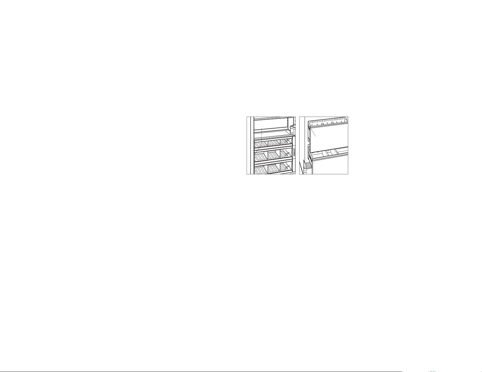
INTEGRIERTE KÜHLTECHNIK
Inhaltsverzeichnis
2 Integrierte Kühltechnik
3 Abmessungen der Öffnung
3 Elektrik
4 Rohrleitungen
4 Vorbereitung
4 Kippschutzhalterung
5 Aufstellen
5 Ausrichtung
6 Wasserleitung
6 Platten
7 Installation der Platte
8 Fertigstellung
Wichtiger Hinweis
Um eine möglichst sichere und efziente Installation dieses
Produkts zu gewährleisten, beachten Sie bitte die folgenden
Arten hervorgehobener Informationen in der gesamten
Anleitung:
WICHTIGER HINWEIS hebt Informationen hervor, die beson-
ders wichtig sind.
VORSICHT ist ein Hinweis auf eine Situation, die bei Nicht-
beachtung der Anweisungen zu geringfügigen Personenoder Sachschäden führen kann.
ACHTUNG benennt eine Gefahr, die zu einer ernsthaften
Verletzung oder zum Tod führen kann, wenn die Vorsichtsmaßnahmen nicht eingehalten werden.
Produktinformationen
Wichtige Produktinformationen, einschließlich der Modellund Seriennummer, sind auf dem Produkttypenschild aufgeführt. Bei Säulenmodellen bendet sich das Typenschild in
der mittleren Schublade in der Nähe der Schubladenführung
gegenüber des Scharniers. Bei hohen und Schubladenmodellen bendet sich das Typenschild im Schrank links von
der oberen Schublade. Siehe die Abbildungen weiter unten.
Wenn Serviceleistungen erforderlich sind, wenden Sie sich
an Ihren Sub-Zero-Vertragshändler.
TYPENSCHILD
TYPENSCHILD
Säulenmodelle
Hohe und Schubladenmodelle
Werkzeuge und Materialien
• Schraubendreher – Flach-, Kreuzschlitz- und
Torx-Ausführung
• Bohrmaschine
• Bohrkronen (bei Betoninstallationen sind Bohrkronen für
Mauerwerk erforderlich)
• Steckschlüsselsatz
• Wasserwaagen, 0,6 m und 1,2 m
• Rohrabschneider
• 0,9 m lange Kupferleitung mit einem Außendurchmesser
1
/4Zoll, Edelstahlgeechtleitung oder PEX-Rohr
von
• Sattelventil
• Material zum Schutz von Einrichtung, Böden und
Schränken während der Installation
2 | Deutsch subzero.com
Page 35

VORBEREITUNG DES INSTALLATIONSORTES
*Die 89 mm breiten Rücklaufprofile sind sichtbar und sollten in Anpassung an die Schränke
endbearbeitet werden – 114 mm für Modell für Außenbereiche.
SEITENANSICHT
Abmessungen der Öffnung
INTEGRIERTE MODELLE
635 mm
ÖFFNUNGSTIEFE
654 mm
FÜR MODELL
FÜR
AUSSENBEREICHE
DRAUFSICHT
H
ÖFFNUNGSHÖHE
19
mm
TYPISCH
89 mm
BEAR-
BEITETES
RÜCKLAUF-
PROFIL*
B B
RAHMENLOSE SCHRÄNKE
ÖFFNUNGSBREITE
VORDERANSICHT
89 mm
BEAR-
BEITETES
RÜCKLAUF-
PROFIL*
RAHMENSCHRÄNKE
B
FÜLL-
STREIFEN
ABMESSUNGEN DER ÖFFNUNG
SÄULEN- UND HOHE MODELLE B H
457 mm Säule 457 mm 2134 mm
610 mm Säule 610 mm 2134 mm
762 mm Säulen- und hohe Modelle 762 mm 2134 mm
914 mm Säulen- und hohe Modelle 914 mm 2134 mm
SCHUBLADE B H
610 mm Schublade 610 mm 876 mm
762 mm Schublade 762 mm 876 mm
914 mm Schublade 914 mm 876 mm
Die Tiefe jedes Weinklimamodells beträgt 610mm. Bei
der Planung der endbearbeiteten Öffnungstiefe muss die
Plattenstärke berücksichtigt werden. Auf allen Seiten der
Öffnung ist ein endbearbeitetes Rücklaufprol mit einer
Breite von mindestens 89 mm erforderlich—114 mm für
Modell für Außenbereiche. Bei Schränken mit Rahmen
ist zusätzliches Füllmaterial hinter dem Frontrahmen
erforderlich, um eine korrekte Installation zu gewährleisten.
Siehe die Abbildung.
DOPPELINSTALLATION
Wenn in einer Doppelinstallation zwei Geräte nebeneinander
installiert werden, wird die Öffnungsbreite der zwei Geräte
addiert. Für diese Installation wird ein Doppelinstallationssatz
benötigt. Wenn kein Doppelinstallationssatz vorgegeben ist,
wird zwischen den Geräten ein mindestens 51 mm breiter
Füllstreifen empfohlen.
Doppelinstallationssätze sind über einen Sub-ZeroVertragshändler lieferbar.
Elektrik
Bei der Installation müssen alle geltenden elektrischen
Vorschriften eingehalten werden und die Geräte müssen
ordnungsgemäß geerdet werden.
Die Stromversorgung muss im schattierten Bereich in der
nachstehenden Zeichnung und Tabelle liegen. Außerdem ist
ein separater Stromkreis nur für dieses Gerät erforderlich.
Das Modell ICBID-24RO (Outdoor-Modell) wurde für den
sicheren Einsatz im Außenbereich konzipiert.
WICHTIGER HINWEIS: Bei Modellen für Innenbereiche wird
ein FI-Schutzschalter nicht empfohlen und kann den Betrieb
unterbrechen.
Bei Modellen für Außenbereiche ist ein FI-Schutzschalter
erforderlich, um das Risiko eines Stromschlags zu
verringern.
Dieses Haushaltsgerät ist mit einem Anschluss ausgestattet,
der für Haushaltsgeräte üblich ist. Der Geräteanschluss
bendet sich unten an der Rückseite des Haushaltsgeräts. Beim Ersetzen des Netzkabels muss darauf geachtet
werden, dass das Ersatzkabel eine Nennleistung von
HO5VV-F3G1.0 oder gleichwertig hat, um einen sicheren
Betrieb zu gewährleisten.
ELEKTROVORAUSSETZUNGEN
Stromversorgung 220-240 V AC, 50/60 Hz
Schutzschalter 10 A
Steckdose geerdet
ORT DER STROMVERSORGUNG
BREITE A
457-mm-Modelle 152mm
610-mm-Modelle 241mm
762-mm-Modelle 318mm
914-mm-Modelle 394mm
LINKE SEITE
DER ÖFFNUNG
114 mm
A
108
E
mm
BODEN
6 mm
VORDERANSICHT
Ort der Stromversorgung
VORSICHT
Die Steckdose muss von einem qualizierten Elektriker
geprüft werden, um sicherzustellen, dass sie mit der
richtigen Polarität verdrahtet ist. Stellen Sie sicher,
dass die Steckdose ordnungsgemäß geerdet ist.
ACHTUNG
Kein Verlängerungskabel bzw. keinen zweipoligen
Stecker verwenden und unter keinen Umständen den
Erdungsstift des Netzkabels entfernen.
Stromschlaggefahr
Netzkabel direkt in eine ordnungsgemäß
geerdete Steckdose einstecken.
Nicht die Erdungsfunktion des Steckers
außer Kraft setzen.
Es darf kein Adapter bzw. Verlänge-
rungskabel verwendet werden.
Die Nichtbeachtung dieser Anweisungen
könnte zu ernsthaften Verletzungen oder
zum Tod führen.
Siehe Installationsanweisungen
subzero.com | 3
Page 36

VORBEREITUNG DES INSTALLATIONSORTES
ENDBEARBEITETER
DRAUFSICHT
RÜCKWAND
13 mm
A
WASSERLEITUNG
152
mm
RECHTE
SEITE
DER
ÖFFNUNG
Rohrleitungen
ACHTUNG
Nur an Trinkwasserversorgung anschließen.
Bei der Installation müssen alle geltenden Vorschriften für
Rohrinstallationen eingehalten werden.
Die Wasserversorgungsleitung sollte im schattierten Bereich
in den nachstehenden Zeichnungen liegen. Die Wasserversorgungsleitung sollte an die Hausversorgungsleitung
angeschlossen werden, und es sollte ein leicht zugängliches Absperrventil installiert werden. Keine Anbohrventile
verwenden. Die Wasserversorgungsleitung muss bündig mit
dem Boden abschließen und darf sich nicht störend auf die
Installation der Kippschutzhalterung auswirken.
Bei Modellen mit einem Eiswürfelbereiter oder Wasserspender ist ein Leitungslter erforderlich, wenn das Wasser
einen hohen Sedimentgehalt hat.
Ein Umkehrosmosesystem kann verwendet werden, falls am
Gerät jederzeit ein konstanter Wasserdruck von 2,4 - 8,3bar
aufrechterhalten wird. Für diese Ausführung wird keine Kupferleitung empfohlen.
VORAUSSETZUNGEN FÜR DIE INSTALLATION VON
ROHRLEITUNGEN
Wasserversorgungsleitung Kupferleitung mit einem Außen-
Wasserdruck 2,4 - 8,3 bar
Wasserleitungsüberstand für
den Anschluss
durchmesser von
Edelstahlgeechtleitung oder
1
/4Zoll,
PEX-Rohr
0,9 m
Vorbereitung
ACHTUNG
Um eine auf Instabilität des Geräts zurückzuführende
Gefahr zu vermeiden, muss es entsprechend den
Anweisungen befestigt werden.
Das Gerät auspacken und auf Schäden überprüfen. Den
Holzsockel entfernen und die Versandschrauben und
Streben entsorgen. Die Verpackungsmaterialien entfernen
und dem Recycling zuführen. Die Sockelleiste, Kippschutzhalterung und Befestigungsmittel dürfen nicht entsorgt
werden.
Die Sockelleiste durch Ausbauen der zwei Montageschrauben entfernen. Siehe Abbildung unten.
SCHRAUBE
Ausbauen der Sockelleiste
Kippschutzhalterung
ACHTUNG
Um ein Abkippen des Geräts nach vorne zu verhindern,
muss die Kippschutzhalterung installiert werden.
Die Rückseite der Kippschutzhalterung muss 610mm von
der Vorderseite des Geräts eingebaut werden (ohne Platte).
Alle Befestigungsmittel der Kippschutzhalterung gemäß
Anweisung für Holz- oder Betonböden verwenden.
WICHTIGER HINWEIS: Wenn bei einer Holz- oder Beton-
bodenausführung die Schrauben Nr. 12 nicht in Kontakt
mit einem Wandpfosten bzw. einer Wandplatte kommen,
die Schrauben und Scheiben Nr. 12 mit den Wandankern
verwenden.
WICHTIGER HINWEIS: Bei manchen Installationen müssen
die Schrauben eventuell in einem Winkel im Estrich oder in
der Fußbodendeckschicht eingeschraubt werden, um die
Kippschutzhalterung an der Rückwand zu befestigen.
HOLZBODENAUSFÜHRUNG
Nach der korrekten Positionierung der Kippschutzhalterung
in der Öffnung Pilotlöcher mit einem Durchmesser von max.
5mm in die Wandpfosten oder Wandplatte bohren. Mit den
Schrauben und Scheiben (Nr. 12) die Halterungen befestigen. Sicherstellen, dass die Schrauben um mindestens
19mm durch das Bodenmaterial und in die Wandpfosten
bzw. Wandplatte eindringen. Siehe die Abbildung und
Tabelle weiter unten.
BETONBODENAUSFÜHRUNG
Nach der korrekten Positionierung der Kippschutzhalterung
in der Öffnung Pilotlöcher mit einem Durchmesser von max.
5mm in die Wandpfosten oder Wandplatte bohren. Löcher
mit einem Durchmesser von 10mm mindestens 38mm
tief in den Beton bohren. Mit den Schrauben und Scheiben
(Nr.12) die Halterungen an der Wand befestigen, und die
Halterungen mit den Ankerkeilen (
3
/8Zoll) am Boden befestigen. Sicherstellen, dass die Schrauben um mindestens
19mm in die Wandpfosten bzw. Wandplatte eindringen.
Siehe die Abbildung und Tabelle weiter unten.
PLATZIERUNG DER KIPPSCHUTZHALTERUNG
BREITE A
457-mm-Modelle 229mm
610-mm-Modelle 305mm
762-mm-Modelle 318mm
914-mm-Modelle 457mm
ORT DER WASSERVERSORGUNG
BREITE A
457-mm-Modelle 76mm
610-mm-Modelle 140mm
762-mm-Modelle 152mm
914-mm-Modelle 229mm
A
A
ENDBEARBEITETER
ESTRICH
HOLZBODEN
BODEN
WANDPLATTE
BETONBODEN
Betonboden
RECHTE SEITE
DER ÖFFNUNG
WANDPLATTE
A
152
BODEN
mm
76 mm
VORDERANSICHT
Ort der Wasserversorgung
4 | Deutsch subzero.com
Holzboden
A
ESTRICH
BODEN
A
38 mm
min
Page 37

VORBEREITUNG DES INSTALLATIONSORTES
INSTALLATION
Kippschutzhalterung
INSTALLATION DER BETONANKERKEILE:
1 Ein Loch mit einem Durchmesser von 10mm und einer
beliebigen Tiefe bohren, die größer als die Mindesteinbindetiefe ist. Das Loch reinigen oder noch tiefer bohren,
um das Bohrmehl auszugleichen.
2 Die Unterlegscheibe und Mutter bündig am Ende des
Ankers einbauen, um das Gewinde zu schützen. Den
Anker durch das zu befestigende Material führen, bis die
Unterlegscheibe bündig am Oberächenmaterial anliegt.
3 Den Anker spreizen, indem die Mutter 3 - 5 Umdre-
hungen über die handfeste Position hinaus gedreht oder
auf ein Drehmoment von 34 Nm festgezogen wird.
ACHTUNG
Es muss sichergestellt werden, dass sich keine Elektroleitungen oder Sanitärinstallationen in diesem Bereich
benden, in die die Schrauben eindringen könnten.
VORSICHT
Stets eine Sicherheitsbrille tragen und sonstige erforderliche Schutzvorrichtungen oder Schutzkleidung
verwenden, wenn Sie Anker installieren oder mit ihnen
hantieren.
Anker werden nicht zur Verwendung in leichtem Mauerwerk wie beispielsweise Blöcke oder Ziegel oder zur
Verwendung in neuem Beton empfohlen, der noch nicht
ausreichend ausgehärtet ist. Zum Bohren von Löchern
für die Anker werden keine Kernbohrer empfohlen.
Aufstellen
VORSICHT
Bevor das Gerät in Position gebracht wird, müssen die
Türen/Schubladen in geschlossener Stellung gesichert
und die Fußbodendeckschicht geschützt werden.
Zum Transportieren des Geräts zur Öffnung einen Transportwagen benutzen. Die vorderen Nivellierfüße werden bis
unter die vorderen Rollen heruntergeschraubt, damit während des Aufstellens die Stabilität verbessert wird. Sobald
das Gerät vor die Öffnung gestellt wird, werden die vorderen
Nivellierfüße ganz hochgeschraubt, damit sich das Gerät in
Position rollen lässt. Die vorderen und hinteren Nivellierfüße
können von vorne aus eingestellt werden, nachdem das
Gerät positioniert wurde.
Wenn das Gerät auf die Rück- oder Seitenwand gelegt
wurde, muss es mindestens 24 Stunden aufrecht stehen,
bevor es an die Stromversorgung angeschlossen wird.
Das Netzkabel in die geerdete Steckdose einstecken und
das Gerät in Position rollen. Prüfen, ob die Kippschutzhalterung richtig eingreift.
Ausrichtung
NIVELLIEREN
Sobald sich das Gerät an seiner endgültigen Position
bendet, können von der Vorderseite aus Höheneinstellungen vorgenommen werden. Mit einem Kreuzschlitzschraubendreher zum Heben im Uhrzeigersinn bzw. zum
Senken gegen den Uhrzeigersinn drehen. Beim Einsatz
einer Bohrmaschine die niedrigste Drehmomenteinstellung
verwenden. Die Nivellierfüße nicht von Hand drehen. Siehe
die Abbildungen weiter unten.
Ist das Gerät korrekt nivelliert oder ausgerichtet, dann ist
es weniger wahrscheinlich, dass Türen bzw. Schubladen
angepasst werden müssen.
WICHTIGER HINWEIS: Das Gerät am Boden, nicht an den
angrenzenden Schränken nivellieren. Dies könnte sich auf
die Bedienung des Geräts, z. B. das Schließen der Tür,
auswirken.
ACHTUNG
Um ein Umkippen des Geräts nach vorne zu vermeiden, müssen die vorderen Nivellierfüße den Boden
berühren.
Nivellieren
HINTERE
ANPASSUNG
VORDERE
ANPASSUNG
subzero.com | 5
Page 38

PLATTENINSTALLATION
Ausrichtung
VERANKERUNG
Stellen Sie die Tiefe des Gerätes so ein, dass es mit dem
umgebenden Gehäuse in Berührung kommt. Sobald ausgerichtet, überprüfen Sie Türen und Schubladen ordnungsgemäß, dann installieren Schrauben in jeder Seite trimmen.
SCHRAUBE
SEITENLEISTE
FRONTRAHMEN
DES
SCHRANK
VORDERSEITE
DES GERÄTS
Verankerung
Wasserleitung
Vor Herstellung des letzten Anschlusses am Gerät die Wasserleitung ausspülen. Dadurch werden alle Ablagerungen
entfernt, die durch die Installation der neuen Wasserleitung
eventuell noch im Rohr verblieben sind. Den Kunststoffschlauch vom Gerät mit dem im Lieferumfang enthaltenen
Armaturanschlusssatz an der hauseigenen Wasserleitung
anschließen. Alle Wasserleitungsarmaturen auf Leckagen
überprüfen.
Die Wasserleitung in der Kerbe unterbringen (siehe nachstehende Abbildung).
WICHTIGER HINWEIS: Wasserleitungen dürfen keinen Tem-
peraturen unter dem Gefrierpunkt ausgesetzt werden.
KERBE
ANSCHLUSS DER
WASSERLEITUNG
Wasserleitung
Edelstahlplatten
Für das Modell für Außenbereiche werden Zubehörplatten
aus Edelstahl von Sub-Zero für Außenanwendungen
benötigt. Edelstahlplatten sind über einen Sub-Zero-Vertragshändler lieferbar.
Die Stärke der Edelstahlplatten für Innenbereiche beträgt 19
mm, und die Edelstahlplatten für Außenbereiche sind 38 mm
stark. Die Tiefe jedes integrierten Modells beträgt 610 mm.
Bei der Planung der endbearbeiteten Öffnungstiefe muss die
Plattenstärke berücksichtigt werden.
In der Regel sind Laibungen 3 mm breit, aber die Laibung
zwischen der oberen und unteren Edelstahlplatte für Außenbereiche ist 6 mm breit, damit das Schloss untergebracht
werden kann.
Maßangefertigte Platten
Bei integrierten Modellen müssen maßangefertigte Türplatten und Griffe eingebaut werden.
Die Stärke der maßangefertigten Platten kann unterschiedlich ausfallen. Die Platte muss mindestens 16mm stark sein,
aber die Stärke kann auch erhöht werden, sofern sie nicht
das in der Tabelle weiter unten aufgeführte Plattenhöchstgewicht überschreitet. Die Tiefe jedes integrierten Modells
beträgt 610mm. Bei der Planung der endbearbeiteten Öffnungstiefe muss die Plattenstärke berücksichtigt werden.
PLATTENANFORDERUNGEN
SÄULE HÖCHSTGEWICHT
457-mm-Modelle 20 kg
610-mm-Modelle 27 kg
762-/914-mm-Modelle 34 kg
HOCH (TÜR) HÖCHSTGEWICHT
762-mm-Modelle 22 kg
914-mm-Modelle 27 kg
SCHUBLADE HÖCHSTGEWICHT
Alle Schubladenplatten 7 kg
PLATTENSTÄRKE MINDESTWERT
Alle Platten 16
Laibungen zwischen Platten können unterschiedlich ausfallen; in der Regel sind Laibungen 3mm breit.
VORSICHT
Wenn eine Platte mit einer Stärke von mehr als 25mm
eingebaut wird, ist eventuell ein Türanschlag von 90°
erforderlich, um Schäden am Gerät und den angrenzenden Schränken zu vermeiden.
VORSICHT
Bei einer kleineren Laibung zwischen Schränken und
dem Gerät besteht die Gefahr, dass man sich beim
Schließen der Tür die Finger ernsthaft quetscht.
Die maßangefertigten Platten müssen auf allen Seiten endbearbeitet werden. Sie sind sichtbar, wenn die Tür geöffnet ist.
Es werden D-förmige Griffe empfohlen. Edelstahlrund- und
Pro-Griffe können von Ihrem Sub-Zero-Vertragshändler
bezogen werden. Die Türgriffe müssen sich in der Nähe der
Kante der Platte gegenüber dem Scharnier benden und
sollten von oben nach unten zentriert sein. Die Schubladengriffe müssen sich nahe der oberen Kante jeder Platte
benden.
6 | Deutsch subzero.com
Page 39

PLATTEN
EDGE OF DOOR PANEL
EDGE OF DOOR PANEL
Maßangefertigte Platten
HÖHE DER TÜRPLATTE
Die Höhe der maßangefertigten Türplatte kann die typische
Plattenhöhe überschreiten, solange sie nicht das Gewichtslimit überschreitet. Siehe Abbildung unten.
45
mm
3 mm
TÜRPLATTE
2134
mm
SCHARNIER
Oberes Abschirmblech (Säulen- und hohe Modelle)
– Seitenansicht
EIN DEKORVOLANT DARF
NICHT ÜBER DIESE
EBENE HINAUSREICHEN
610 mm
ZUR RÜCKSEITE
DES GERÄTS
SOCKELLEISTENFREIRAUM
(AUSSER BEIM MODELL FÜR AUSSENBEREICHE)
Die Höhe des Sockelleistenbereichs kann über die typische
Höhe hinausragen, solange nicht die in der nachstehenden
Abbildung genannten Abmessungen überschritten
werden. Bei Sockelleistenhöhen von 51mm bis 98mm
ist ein Zubehörsatz für eine reduzierte Sockelleistenhöhe
erforderlich, der über einen Sub-Zero-Vertragshändler
bezogen werden kann.
SCHARNIER**
TÜRPLATTE
102 mm*
BIS
152 mm
VOM BODEN
*Bei Höhen von 51 mm bis 98 mm ist ein Zubehörsatz erforderlich.
**Nur Säulenmodelle
Sockelleiste – Seitenansicht
ENTLÜFTUNGS-
LAMELLEN
610 mm
ZUR RÜCKSEITE
DES GERÄTS
MAX.
ANPASSUNG
SOCKELLEISTE
29 mm
EINE DEKORSOCKELLEISTE
DARF NICHT ÜBER DIESE
EBENE HINAUSRAGEN
Installation der Platte
INSTALLATION DER TÜRPLATTE
Die typischen Plattenabmessungen basieren auf einer
endbearbeiteten Höhe von 2134mm mit 3mm breiten Laibungen. Bei Platten, die die typischen Abmessungen überschreiten, muss die Vorlagenplatzierung angepasst werden.
Bei hohen Modellen sollte zuerst die Türplatte, dann die
obere und zuletzt die untere Schubladenplatte eingebaut
werden.
Die Platte mit der Frontseite nach unten auf eine geschützte
Arbeitsäche legen. Die Vorlage so positionieren, dass
sie bündig mit der Oberseite und den Seiten der Platte
abschließt. Sicherstellen, dass die richtige Seite der Vorlage
verwendet wird; dann Löcher markieren und bohren. Siehe
Abbildung unten.
Bei hohen Modellen die Kerbe in der Vorlage auf die Unterseite der Türplatte ausrichten; dann Löcher markieren und
bohren. Siehe Abbildung unten.
OBERSEITE DER TÜRPLATTE
TOP OF
DOOR PANEL
84" APPLICATION
83 7/8" ACTUAL
DOOR PANEL
BOTTOM OF
USE TABS FOR HINGE
SIDE PANEL EDGE ON
DUAL INSTALLATION
Türplattenvorlage – oben
Türplattenvorlage – unten
(nur hohe Modelle)
BOTTOM OF
DOOR PANEL
DUAL INSTALLATION
SIDE PANEL EDGE ON
USE TABS FOR HINGE
83 7/8" ACTUAL
84" APPLICATION
DOOR PANEL
TOP OF
UNTERSEITE
DER TÜRPLATTE
Verwenden Sie einen Torx-Antrieb, um teilweise eine Nr.
8 x 13 mm Schraube in das zweite Loch von der Oberseite
auf jeder Seite des Paneels einzufügen. Die Schrauben
sollten ca. 4mm über der Platte hervorstehen und tragen
während der Installation das Gewicht der Platte.
Die Stützschrauben auf der Rückseite der Platte auf die
geschlitzten Löcher auf beiden Türmontagehalterungen
ausrichten. Zur besseren Ausrichtung kann die Tür leicht
geöffnet werden. Sobald die Platte von den Schrauben
abgestützt wird, jeweils eine Schraube Nr. 8 x 13mm
teilweise in das zweite Loch von unten auf jeder Seite der
Platte einführen, aber nicht festziehen.
VORSICHT
Bei einer kleineren Laibung zwischen Schränken und
dem Gerät besteht die Gefahr, dass man sich die
Finger ernsthaft einklemmt oder quetscht, wenn beim
Schließen der Tür die Finger in die Öffnung geraten.
RÜCKSEITE
DER TÜRPLATTE
Türplattenmontage
subzero.com | 7
Page 40

INSTALLATION DER PLATTE
LEFT EDGE OF DRAWER PANEL
INSTALLATION
Installation der Platte
INSTALLATION DER SCHUBLADENPLATTE
Die Platte mit der Frontseite nach unten auf eine geschützte
Arbeitsäche legen. Die Vorlage so positionieren, dass
sie bündig mit der Oberseite und den Seiten der Platte
abschließt. Sicherstellen, dass die richtige Seite der Vorlage
verwendet wird; dann Löcher markieren und bohren. Siehe
Abbildung unten.
Verwenden Sie einen Torx-Antrieb, um teilweise eine Nr.
8 x 13 mm Schraube in das zweite Loch von der Oberseite
auf jeder Seite des Paneels einzufügen. Die Schrauben
sollten ca. 4mm über der Platte hervorstehen und tragen
während der Installation das Gewicht der Platte.
Die Stützschrauben auf der Rückseite der Platte auf die
geschlitzten Löcher auf beiden Schubladenmontagehalterungen ausrichten. Siehe Abbildung unten. Zur besseren
Ausrichtung kann die Schublade leicht geöffnet werden.
Sobald die Platte von den Schrauben abgestützt wird,
jeweils eine Schraube Nr. 8 x 13mm teilweise in das zweite
Loch von unten auf jeder Seite der Platte einführen, aber
nicht festziehen.
OBERSEITE DER SCHUBLADENPLATTE
TOP OF
DRAWER PANEL
TOP HOLES
FOR UPPER
AND LOWER
DRAWERS
WER PANEL
Schubladenplattenvorlage
– oben
RÜCKSEITE DER
SCHUBLADENPLATTE
Schubladenplattenmontage
PLATTENANPASSUNG
Tür und/oder Schubladen schließen; es können jetzt Anpassungen vorgenommen werden, um Platten und Laibungen
auszurichten.
Zur seitlichen Anpassung die Platten seitlich verschieben,
dann einbauen und alle Montageschrauben festziehen.
Für Anpassungen nach oben und unten bzw. nach innen
und außen die Halterungsschrauben etwas lösen. Je
nachdem, wie viele Anpassungen erforderlich sind, hilft es
eventuell, alle Halterungsschrauben zu lösen. Dadurch ist
eine maximale Anpassung möglich. Nach dem Lösen der
Halterungsschrauben die Nocken drehen, um die Anpassungen vorzunehmen. Nachdem alle Anpassungen gemacht
wurden, werden alle Halterungsschrauben festgezogen.
Siehe die Abbildungen weiter unten.
NOCKE NACH
INNEN UND AUSSEN
HALTERUNGS-
SCHRAUBEN
Anpassung nach innen und
außen
HALTERUNGS-
SCHRAUBEN
NOCKE NACH
OBEN UND UNTEN
Einstellung nach oben und
unten
Fertigstellung
INSTALLATION DES TÜRPROFILS
Nach Anpassen der Platten die Zierleiste an der Tür/den
Schubladen anbringen. Zum Einbauen ganz oben anfangen
und die Leiste auf die vorderen und hinteren Flansche in
der Halterung ausrichten und einrasten lassen. Dabei die
Zierleiste zur Rückseite der Platte hin drücken. Nach dem
Sichern des oberen Teils arbeiten Sie sich nach unten fort,
bis der Rest der Leiste vollständig installiert wurde. Siehe
die Abbildungen weiter unten.
TÜRPROFIL
VORDERER
FLANSCH
HINTERER
FLANSCH
Türprol
EINBAUEN DER SEITENLEISTE
Die seitliche Zierleiste an der Griffseite von hohen und
Säulenmodellen einbauen. Die Seitenleiste rastet auf der
Halterung ein, die an der Griffseite des Geräts angebracht
ist. Siehe Abbildung unten.
Halterungsansche
EINBAUEN DER OBEREN LEISTE
Die oberen Leistenstreifen anhand der Kerbe am einen
unteren Ende identizieren; dieser Leistenstreifen passt auf
die Scharnierseite des Geräts.
Das äußere Ende des jeweiligen Leistenstreifens hinter der
senkrechten Seitenleiste einführen. Den Schnappverschluss
in der Seitenhalterung aus Kunststoff einrasten lassen und
die Platte so weit wie möglich nach außen schieben. Siehe
Abbildung unten.
Das Innenende der jeweiligen Platte in die Seitenansch der
mittleren Haube neben der Zugangsöffnung zum Wasserlter drehen. Auf den Leistenstreifen drücken, damit er
einrastet. Siehe Abbildung unten.
Obere Innenleiste
Obere Außenleiste
Seitenleiste
8 | Deutsch subzero.com
Page 41

INSTALLATION
Fertigstellung
INSTALLATION DER SOCKELLEISTE
Die Sockelleiste positionieren und mit den beiden Montageschrauben einbauen. Siehe Abbildung unten. Die Sockelleiste muss für Wartungszwecke ausgebaut werden können.
Der Boden darf beim Ausbauen nicht behindern.
Bei Modellen für Innenbereiche kann an der ab Werk eingebauten Sockelleiste maximal eine 152 mm hohe dekorative Sockelleiste angebracht werden. Die zwei Reihen mit
Entlüftungslamellen können abgedeckt werden, wenn die
Türplatte mindestens einen Abstand von 102 mm von der
Fußbodendeckschicht wahrt. Am Modell für Außenbereiche
kann keine dekorative Sockelleiste angebracht werden.
Zum Einbauen einer dekorativen Sockelleiste das Trägerpapier von den Magneten abziehen und die Sockelleiste
an den Magneten anbringen. Die Magneten können auch
in ihrer Position festgeklebt werden, um die Haftkraft zu
verbessern. Bei der Anbringung mittels Magneten kann die
dekorative Sockelleiste nach Bedarf entfernt werden.
Das Gerät einschalten, indem Sie auf der Schaltblende „Ein“
berühren.
TÜRANSCHLAG VON 90°
In die Scharniere von hohen und Säulengeräten ist ein Türanschlag von 105° integriert. Um die Türöffnung auf 90° zu
begrenzen, die Tür auf etwas weniger als 90° öffnen. Dann
die vorhandenen Klammern mit einer standardmäßigen
Schraubendreherklinge von den Scharnieren entfernen. Die
90°-Klammern, die sich in der Plastiktüte mit der Produktliteratur benden, in jedes Scharnier einführen. Siehe
Abbildung unten.
KLAMMER
Türanschlag von 90°
SCHRAUBEMAGNET
Installation der Sockelleiste
Sub-Zero, Sub-Zero & Design, Sub-Zero & Snowake Design, Dual Refrigeration, The Living Kitchen, Great American Kitchens The Fine Art of Kitchen Design, Wolf, Wolf & Design, Wolf Gourmet, W & Design, rotfarbige Schaltknebel, Cove und Cove & Design sind eingetragene Marken und Servicemarken der Sub-Zero Group, Inc. und ihrer
Tochtergesellschaften. Alle anderen Marken sind das Eigentum ihrer jeweiligen Besitzer in den Vereinigten Staaten und anderen Ländern.
subzero.com | 9
Page 42

GEÏNTEGREERDE KOELING
Inhoud
2 Geïntegreerde koeling
3 Afmetingen van de opening
3 Elektriciteit
4 Sanitair
4 Voorbereiding
4 Anti-omvalbeugel
5 Plaatsing
5 Uitlijning
6 Waterleiding
6 Panelen
7 Plaatsing van panelen
8 Afronding
Belangrijke opmerking
Let voor een veilige en efciënte installatie en bediening van
dit product op de volgende soorten aanduidingen in deze
handleiding:
BELANGRIJK duidt op informatie van bijzonder belang.
VOORZICHTIG duidt op een situatie waar licht letsel of
schade kan optreden als instructies niet worden gevolgd.
WAARSCHUWING duidt op gevaar voor ernstig letsel
of overlijden als de voorzorgsmaatregelen niet worden
nageleefd.
Productgegevens
Belangrijke productgegevens zoals het model en
serienummer staan op het producttypeplaatje. Voor
zuilmodellen bevindt het typeplaatje zich in de middelste
lade bij de ladegeleider tegenover het scharnier. Voor
hoog- en lademodellen bevindt het typeplaatje zich in
de kast aan de linkerkant van de bovenste lade. Zie de
afbeeldingen hieronder.
Neem voor onderhoud contact op met uw erkende
Sub-Zero dealer.
TYPEPLAAT
TYPEPLAAT
Zuilmodellen
Hoge en lademodellen
Gereedschap en materialen
• Schroevendraaiers: standaard, kruiskop en Torx.
• Boormachine.
• Boorijzers (voor plaatsing in beton).
• Standaard stopcontact en moersleutelset.
• 0,6 m en 1,2 m waterpas.
• Buissnijder.
1
• 0,9 m of
• Zadelventiel.
• Materiaal voor de bescherming van het huis, de vloeren
/4 inch O-koper, gevlochten roestvrij staal of
PEX buizen.
en kasten tijdens de installatie.
2 | Nederlands
Page 43

Voorbereiding van locatie
*Afgewerkte randen van 89 mm zullen zichtbaar zijn; deze moeten worden afgewerkt zodat
ze passen bij het kastwerk — 114 mm voor buitenmodel.
ZIJ
Afmetingen van de opening
GEÏNTEGREERDE MODELLEN
H
HOOGTE VAN
OPENING
AANZICHT
635 mm
DIEPTE VAN
OPENING
654 mm
VOOR
BUITENMODEL
BOVENAANZICHT
B
BREEDTE VAN OPENING
VOORAANZICHT
AFMETINGEN VAN DE OPENING
ZUIL EN HOOG B H
457 mm zuil 457 mm 2134 mm
610 mm zuil 610 mm 2134 mm
762 mm zuil en hoog 762 mm 2134 mm
914 mm zuil en hoog 914 mm 2134 mm
LADE B H
610 mm lade 610 mm 876 mm
762 mm lade 762 mm 876 mm
914 mm lade 914 mm 876 mm
De diepte van de wijnopslagmodellen is 610 mm. Zorg voor
voldoende paneeldikte bij het inrichten van de afgewerkte
openingdiepte. Aan alle kanten van de opening is een
afgewerkte rand van minimaal 89 mm benodigd, of 114 mm
voor buitenmodellen. Bij kabinetten met omlijsting is
extra afgewerkte vulmateriaal achter de omlijsting aan
de voorkant nodig voor een correcte installatie. Zie de
afbeelding.
DUBBELE INSTALLATIE
Wanneer u bij een dubbele installatie twee apparaten naast
elkaar plaatst, is de openingsbreedte de breedte van de
twee eenheden samen. Voor deze installatie hebt u een
dubbele installatiekit nodig. Als geen dubbele installatiekit is
opgegeven, is er een vulstrook van minimaal 51 mm nodig
tussen de apparaten.
Dubbele installatiekits zijn verkrijgbaar bij een erkende
Sub-Zero dealer.
Elektriciteit
De installatie moet voldoen aan alle geldige elektrische
codes en correct worden geaard.
De elektrische voeding moet zich in de afbeelding en graek
hieronder binnen het gearceerde gebied bevinden. Er dient
een apart circuit voor de stroomtoevoer naar dit toestel te
worden gebruikt. Model ICBID-24RO is geschikt en veilig
voor gebruik in buitentoepassingen.
BELANGRIJK: Voor binnenmodellen wordt een aardelek-
schakelaar niet aanbevolen aangezien dit storingen aan de
werking kan veroorzaken.
Voor het buitenmodel is een aardlekschakelaar nodig om het
risico op elektrische schokken te verlagen.
Dit apparaat is uitgerust met een ingangsvoorziening voor
apparaten. De ingangsvoorziening bevindt zich aan de
onderkant van het apparaat. Controleer voor een veilige
werking bij het vervangen van het netsnoer of het vervangende snoer een maximale belasting heeft van HO5VVF3G1.0 of gelijkwaardig.
ELEKTRISCHE VEREISTEN
Voedingsspanning 220-240 V wisselstroom, 50/60 Hz
Vermogenschakelaar 10 amp
Stopcontact geaard
LOCATIE ELEKTRISCHE VOEDING
BREEDTE A
457 mm modellen 152 mm
610 mm modellen 241 mm
762 mm modellen 318 mm
914 mm modellen 394 mm
VOORZICHTIG
De bedrading van het stopcontact moet door een
gekwaliceerde elektricien worden gecontroleerd op
de juiste polariteit. Controleer of het stopcontact goed
is geaard.
WAARSCHUWING
Gebruik geen verlengsnoer, twee-polige adapter en
verwijder niet de aardestekker.
Gevaar voor
elektrische
schok
Steek de stekker direct in een goed geaard
stopcontact.
Omzeil de aarding van de stekker niet.
Gebruik geen adapter of verlengsnoer.
Het negeren van deze instructies kan
ernstig letsel of de dood tot gevolg hebben.
Installatie-instructies
19
mm
GEBRUIKELIJK
89 mm
AFGEWERKTE
RUIMTE*
B B
KASTWERK ZONDER
OMLIJSTING
89 mm
AFGEWERKTE
RUIMTE*
KASTWERK MET
OMLIJSTING
VULLER
LINKERKANT
VAN OPENING
114 mm
A
108
E
mm
VLOER
6 mm
VOORAANZICHT
Locatie elektrische voeding
subzero.com | 3
Page 44

Voorbereiding van locatie
BOVENAANZICHT
ACHTERWAND
13 mm
A
WATERLIJN
152
mm
RECH-
TERKANT
VAN
OPENING
Sanitair
WAARSCHUWING
Alleen op drinkwatertoevoer aansluiten.
De installatie moet voldoen aan alle geldende sanitaire
richtlijnen.
De watertoevoerslang moet zich in het gearceerde gebied in
de onderstaande illustratie bevinden. De watertoevoerslang
moet op de waterleiding worden aangesloten met een
gemakkelijk toegankelijke afsluitklep. Gebruik geen afsluiter
met aanboorzadel. De watertoevoerslang moet gelijk zijn
aan de vloer en de anti-omvalbeugel niet belemmeren.
Voor modellen met een ijsmaker of waterkoeler is een inline
lter nodig als het water veel sediment bevat.
Er kan van een omgekeerd osmosesysteem gebruik worden
gemaakt, mits er constante waterdruk van 2,4-8,3 bar aan
het apparaat wordt geleverd. Een koperen leiding wordt
voor deze toepassing niet aanbevolen.
SANITAIRVEREISTEN
Watertoevoerleiding.
Tegendruk van het water 2,4 - 8,3 bar
Extra waterleiding voor aansluiting 0,9 m
LOCATIE WATERTOEVOER
BREEDTE A
457 mm modellen 76 mm
610 mm modellen 140 mm
762 mm modellen 152 mm
914 mm modellen 229 mm
1
/4 inch OD-koper, gevlochten
roestvrij staal of PEX-buizen.
Voorbereiding
WAARSCHUWING
Om gevaar door instabiliteit van het apparaat te
voorkomen, moet het volgens de instructies worden
vastgezet.
Haal het apparaat uit de bekisting en controleer op
beschadigingen. Verwijder de houten onderkant en gooi
de transportbouten en beugels weg. Verwijder al het
verpakkingsmateriaal. Gooi de stootplaat, anti-omvalbeugel
en toebehoren niet weg.
Verwijder de stootplaat door de twee schroeven los te
draaien. Zie de afbeelding hieronder.
SCHROEF
Stootplaat verwijderen
Anti-omvalbeugel
WAARSCHUWING
Om te voorkomen dat het apparaat naar voren kantelt,
moet de anti-omvalbeugel worden geplaatst.
De achterkant van de anti-omvalbeugel moet 610 mm vanaf
de voorzijde van het apparaat (zonder panelen) worden
geplaatst.
Gebruik alle anti-omvaltoebehoren volgens de instructies
voor houten of betonnen vloeren.
BELANGRIJK: Voor toepassingen op houten of betonnen
vloeren, als de #12 schroeven geen muurplank of muurplaat
raken, gebruikt u de #8 schroeven en #12 ringen met de
muurankers.
BELANGRIJK: Bij sommige installaties moeten wegens de
ondervloer of de afgewerkte vloer de gebruikte schroeven
worden gebogen om de anti-omvalbeugel aan de
achterwand vast te schroeven.
TOEPASSING OP HOUTEN VLOER
Nadat u de anti-omvalbeugel in de opening heeft gevonden,
boort u proefgaten van maximaal 5 mm diameter in de
muurplanken of wandplaat. Gebruik de #12 schroeven
en ringen om de beugels vast te maken. Controleer dat
de schroeven door het vloermateriaal heengaan en in de
muurplanken of wandplaat minimaal 19 mm binnendringen.
Zie de illustratie en de graek hieronder.
TOEPASSING OP BETONNEN VLOER
Nadat u de anti-omvalbeugel in de opening heeft gevonden,
boort u proefgaten van maximaal 5 mm diameter in
de muurplanken of wandplaat. Boor gaten van 10mm
diameter in het beton minimaal 38 mm diep. Gebruik de
#12 schroeven en ringen om de beugels aan de muur te
bevestigen en gebruik de wigankers van
3
/8 inch om de
beugels aan de vloer te bevestigen. Controleer dat de
schroeven minimaal 19 mm in de muurplanken of wandplaat
binnendringen. Zie de illustratie en de graek hieronder.
PLAATSING ANTI-OMVALBEUGEL
BREEDTE A
457 mm modellen 229 mm
610 mm modellen 305 mm
762 mm modellen 318 mm
914 mm modellen 457 mm
RECHTERKANT
VAN OPENING
A
76 mm
VLOER
VOORAANZICHT
Locatie watertoevoer
4 | Nederlands
152
mm
A
WANDPLAAT
ONDERVLOER
HOUTEN VLOER
Houten vloer
A
AFGEWERKTE
VLOEREN
A
WANDPLAAT
ONDERVLOER
BETONNEN
VLOER
Betonnen vloer
A
AFGEWERKTE
VLOEREN
38 mm
min
Page 45

VOORBEREIDING VAN LOCATIE
T
INSTALLATIE
Anti-omvalbeugel
INSTALLATIE BETONWIGANKER:
1 Boor een gat van 10 mm diameter met een grotere diepte
dan de minimale verankering. Maak het gat schoon of
boor wat dieper om rekening te houden met gruis.
2 Draai de ring en de moer op gelijke hoogte met het eind
van het anker om de draden te beschermen. Drijf het
anker door het te bevestigen materiaal totdat de ring
gelijk staat aan het oppervlak.
3 Breid het anker uit door de moer 3–5 draaien vast
te draaien voorbij de handvaste positie of naar
34newton-meters torsie.
WAARSCHUWING
Controleer dat er in het gebied waar de schroeven
kunnen doordringen geen elektrische draden of
buizen zijn.
VOORZICHTIG
Draag altijd een veiligheidsbril en andere nodige
beschermende voorzieningen of kleding bij het
installeren of werken met ankers.
Ankers worden niet aanbevolen voor gebruik in
metselwerk van lichtgewicht materiaal zoals blokken
of baksteen, of voor gebruik in nieuw beton dat niet
voldoende tijd heeft gehad om uit te harden. Het
gebruik van kernboren wordt niet aanbevolen voor
het boren van gaten voor de ankers.
Plaatsing
VOORZICHTIG
Voordat u het apparaat naar de gewenste positie brengt,
sluit de deur/lades en bescherm afgewerkte vloeren.
Gebruik een rijdend plateau om het apparaat naar de
opening te verplaatsen. De voorste nivelleerpoten steken
uit onder de voorste rollers voor meer stabiliteit tijdens
de plaatsing. Trek als het apparaat voor de opening is
geplaatst de voorste nivelleerpoten in zodat het apparaat
naar de gewenste positie kan worden gerold. De voorste en
achterste nivelleerpoten kunnen vanaf de voorkant worden
aangepast als het apparaat op zijn plaats staat.
Als het apparaat op zijn rug of zijkant is geweest, moet het
minstens 24 uur rechtop staan voordat u de stroom aansluit.
Steek de stekker van het netsnoer in het geaarde
stopcontact en rol het apparaat op zijn plaats. Controleer of
de anti-omvalbeugel goed vastklikt.
Uitlijning
WATERPAS ZETTEN
Zodra het apparaat in positie is, kan de hoogte vanaf
de voorkant worden ingesteld. Draai rechtsom met een
kruiskopschroevendraaier om het apparaat te verhogen
of linksom om het te verlagen. Gebruik de laagste torsieinstelling bij gebruik van een boormachine. Draai de
nivelleerpoten niet met de hand aan. Zie de afbeeldingen
hieronder.
Als het apparaat goed waterpas staat, zullen aanpassingen
aan de deur of lades minder noodzakelijk zijn.
BELANGRIJK: Zet het apparaat waterpas met de vloer, niet
met omliggende kasten. Hierdoor kan de werking van het
apparaat worden belemmerd, zoals het sluiten van de deur.
WAARSCHUWING
Om te voorkomen dat het apparaat naar voren kantelt,
moeten de voorste nivelleerpoten in contact staan met
de vloer.
AANPASSING
AAN VOORKAN
AANPASSING
AAN ACHTERKANT
Waterpas zetten
subzero.com | 5
Page 46

PANELENINSTALLATIE
Uitlijning
VERANKEREN
Pas de diepte van het apparaat aan om in te passen met de
omliggende kast. Zodra de uitlijning is afgerond, controleer
de deuren en de laden op de juiste manier, en installeer
vervolgens de schroeven in elke zijkant.
SCHROEF
TRIM
ZIJKANT
FRAME
VOORKANT
KASTWERK
VOORKANT
VAN APPARAAT
Verankeren
Waterleiding
Leeg de waterleiding voorafgaand aan de laatste aansluiting
op het apparaat. Hiermee verwijdert u alle vuil dat in de
slang aanwezig kan zijn door het installeren van de nieuwe
waterleiding. Sluit de plastic slang van het apparaat aan
op de watervoorziening met behulp van de bijgeleverde
montagekit. Controleer alle aansluitingen van de
waterleiding op lekken.
Zoek de waterleiding in de inkeping zoals aangegeven in de
afbeelding hieronder.
BELANGRIJK: Waterleidingen mogen niet aan
vriestemperaturen worden blootgesteld.
INKEPING
WATERLIJNVERBINDING
Waterleiding.
RVS-panelen
Voor het buitenmodel zijn roestvrij stalen buitenpanelen van
Sub-Zero nodig. Roestvrij stalen panelen zijn verkrijgbaar bij
erkende Sub-Zerodealers.
De dikte van de roestvast stalen binnenpanelen is 19 mm en
van de roestvast stalen buitenpanelen is 38 mm. De diepte
van elk geïntegreerd model is 610 mm. Houd rekening met
de dikte van de panelen bij het plannen van de diepte van
de afgewerkte opening.
Diepten van 3 mm zijn gebruikelijk, maar de diepte tussen
de bovenste en onderste roestvrij stalen buitenpanelen is
6 mm in verband met de afmetingen van het slot.
Aangepaste panelen
Voor geïntegreerde modellen moeten aangepaste
deurpanelen en handgrepen worden geïnstalleerd.
De dikte van het gekozen paneel kan variëren. Het paneel
moet ten minste 16 mm dik zijn, maar mag nog dikker zijn
zolang het maximale gewicht van het paneel niet groter is
dan wat is aangegeven in onderstaande tabel. De diepte
van de geïntegreerde modellen is 610 mm. Zorg voor
voldoende paneeldikte bij het inrichten van de afgewerkte
openingdiepte.
PANEELVEREISTEN
ZUIL MAX GEWICHT
457 mm modellen 20 kg
610 mm modellen 27 kg
762 / 914 mm modellen 34 kg
HOOG (DEUR) MAX GEWICHT
762 mm modellen 22 kg
914 mm modellen 27 kg
LADE MAX GEWICHT
Alle ladepanelen 7 kg
PANEELDIKTE MINIMUM
Alle panelen 16
Diepten tussen panelen kunnen variëren, 3 mm is
gebruikelijk.
VOORZICHTIG
Bij het aanbrengen van een paneel dikker dan 25 mm,
moet mogelijk gebruik worden gemaakt van de 90°
stop ter voorkoming van schade aan het apparaat en
aan de aangrenzende kasten.
VOORZICHTIG
Met minder tussenruimte tussen kasten en het
apparaat kunnen vingers bekneld komen te zitten
wanneer de deur wordt gesloten.
Werk alle zijden van aangepaste panelen af. Deze zijn
zichtbaar als de deur geopend is.
D-stijl handgrepen worden aanbevolen. Roestvrij stalen
buisvormige en pro-handgrepen zijn verkrijgbaar bij een
erkende Sub-Zerodealer. Deurkrukken moeten aan de rand
van het paneel tegenover het scharnier worden aangebracht
en verticaal in het midden. Ladehandgrepen moeten aan de
bovenkant van de panelen worden aangebracht.
6 | Nederlands
Page 47

PANELEN
EDGE OF DOOR PANEL
EDGE OF DOOR PANEL
Aangepaste panelen
HOOGTE VAN DEURPANEEL
De hoogte van het aangepaste deurpaneel mag hoger zijn
dan gebruikelijk zolang het maximale gewicht niet wordt
overschreden. Zie de afbeelding hieronder.
45
mm
3 mm
DEUR-
PANEEL
2134
mm
SCHAR-
NIER
Bovenste rand (zuil en hoge modellen) — zijaanzicht
EEN DECORATIEVE RAND
MAG NIET VERDER KOMEN
DAN DIT VLAK
610 mm
TOT ACHTERZIJDE
VAN APPARAAT
RUIMTE VOOR STOOTPLAAT
(GELDT NIET VOOR HET BUITENMODEL)
De hoogte van de teenstootplaat mag hoger zijn dan
gebruikelijk zolang de afmetingen in de onderstaande
afbeelding niet worden overschreden. Voor een hoogte van
van 51 mm tot 98 mm van de teenstootplaat is een kleinere
teenstootaccessoire nodig die verkrijgbaar is via een
erkende Sub-Zero dealer.
SCHAR-
NIER**
DEUR-
PANEEL
51 mm*
TOT
152 mm
VANAF
VLOER
* Voor 51 mm tot 98 mm is salesaccessoire nodig
** Alleen zuilmodellen
Teenstootplaat — zijaanzicht
LUCHTROOSTERS
610 mm
TOT ACHTERZIJDE
VAN APPARAAT
29 mm
MAX
AANPASSING
TEENTRAP
EEN DECORATIEVE
TEENSTOOTPLAAT
MAG NIET VOORBIJ DIT
VLAK UITSTEKEN
Plaatsing van panelen
PLAATSING VAN DEURPANEEL
Gebruikelijke afmetingen van panelen zijn gebaseerd op
een afgewerkte hoogte van 2134 mm met 3 mm dagkant.
Plaatsing van de sjabloon moet worden aangepast voor
grotere panelen.
Bij hoge modellen moet eerst het deurpaneel worden
geïnstalleerd, gevolgd door het bovenste en onderste
lade-panel.
Plaats het paneel met de voorkant naar beneden op een
beschermd werkoppervlak. Plaats de sjabloon gelijk met
de bovenkant en de zijkanten van het paneel. Controleer of
de goede kant van de sjabloon wordt gebruikt, vervolgens
markeren en gaten boren. Zie de afbeelding hieronder.
Bij hoge modellen, lijn de inkeping in de sjabloon uit met
de onderkant van het deurpaneel, vervolgens markeren en
gaten boren. Zie de afbeelding hieronder.
BOVENKANT VAN DEURPANEEL
TOP OF
DOOR PANEL
84" APPLICATION
83 7/8" ACTUAL
DOOR PANEL
BOTTOM OF
USE TABS FOR HINGE
SIDE PANEL EDGE ON
DUAL INSTALLATION
Sjabloon deurpaneel: bovenkant Sjabloon deurpaneel: onderkant
(alleen voor hoge modellen)
BOTTOM OF
DOOR PANEL
DUAL INSTALLATION
SIDE PANEL EDGE ON
USE TABS FOR HINGE
83 7/8" ACTUAL
84" APPLICATION
DOOR PANEL
TOP OF
ONDERKANT VAN
DEURPANEEL
Gebruik een Torx drive om een #8 x 13 mm schroef in het
tweede gat van de bovenkant aan weerszijden van het
paneel te plaatsen. De schroeven moeten ongeveer 4 mm
van het paneel uitsteken en het gewicht van het paneel
dragen tijdens de installatie.
Lijn de steunschroeven aan de achterzijde van het paneel
uit met de sleufgaten op beide montagebeugels van
de deur. Door de deur iets te openen vergemakkelijkt
het uitlijnen. Als het paneel door de schroeven wordt
ondersteund, draait u een #8 x 13 mm schroef gedeeltelijk
in het tweede gat van boven aan elke kant van het paneel
in, maar draai niet vast.
VOORZICHTIG
Hoe minder dagkant tussen kasten en het apparaat,
hoe groter de kans dat vingers bekneld raken in de
opening als de deur wordt gesloten.
ACHTERKANT VAN
DEURPANEEL
Plaatsing van deurpaneel
subzero.com | 7
Page 48

PLAATSING VAN PANELEN
LEFT EDGE OF DRAWER PANEL
INSTALLATIE
Plaatsing van panelen
PLAATSING VAN LADEPANEEL
Plaats het paneel met de voorkant naar beneden op een
beschermd werkoppervlak. Plaats de sjabloon gelijk met
de bovenkant en de zijkanten van het paneel. Controleer of
de goede kant van de sjabloon wordt gebruikt, vervolgens
markeren en gaten boren. Zie de afbeelding hieronder.
Gebruik een Torx drive om een #8 x 13 mm schroef in het
tweede gat van de bovenkant aan weerszijden van het
paneel te plaatsen. De schroeven moeten ongeveer 4 mm
van het paneel uitsteken en het gewicht van het paneel
dragen tijdens de installatie.
Lijn de steunschroeven aan de achterzijde van het paneel
uit met de sleufgaten op beide montagebeugels van de
lade. Zie de afbeelding hieronder. Door de lade iets te
openen vergemakkelijkt het uitlijnen. Als het paneel door
de schroeven wordt ondersteund, draait u een #8 x 13 mm
schroef gedeeltelijk in het tweede gat van boven aan elke
kant van het paneel in, maar draai niet vast.
BOVENKANT VAN LADEPANEEL
TOP OF
DRAWER PANEL
TOP HOLES
FOR UPPER
AND LOWER
DRAWERS
WER PANEL
Sjabloon ladepaneel: bovenkant Plaatsing van ladepaneel
ACHTERKANT VAN
LADEPANEEL
AANPASSING PANEEL
Sluit de deur en/of laden, zodat nu aanpassingen kunnen
worden aangebracht om de panelen op de dagkant uit te
lijnen.
Voor aanpassing van zijkant tot zijkant, legt u de panelen
naast elkaar en draait u alle schroeven in en vast.
Voor op- en neergaande en in-en-uitaanpassingen, draait u de
beugelschroeven iets los. Afhankelijk van hoeveel aanpassing
nodig is, kan het handig zijn om alle beugelschroeven los te
draaien om zo maximale aanpassing te verkrijgen. Zodra de
beugelschroeven zijn losgedraaid, draait u de nokken om
aanpassingen te maken. Daarna draait u de beugelschroeven
weer vast. Zie de afbeeldingen hieronder.
BEUGEL-
SCHROEVEN
OP-EN-NEER
CAM
Aanpassing boven-en-onder
BEUGEL-
SCHROEVEN
Aanpassing in-en-uit
IN-EN-UIT CAM
Afronding
PLAATSING VAN DEURTRIM
Nadat de panelen zijn gecorrigeerd, brengt u de decoratieve
zijtrim aan op de deur/laden. Begin hiervoor aan de bovenkant
en lijn de trim uit met de voorste en achterste enzen op de
beugel, klik dan vast door de trim naar de achterkant van het
paneel te duwen. Zodra de bovenkant vast zit, kunt u verder
gaan naar beneden totdat de resterende trim volledig vast zit.
Zie de afbeeldingen hieronder.
DEURTRIM
VOORSTE
FLENS
ACHTERSTE
FLENS
Deurtrim
PLAATSING VAN TRIM ZIJKANT
Plaats de decoratieve trimstrip aan de handgreepzijde van
de hoge en zuilmodellen. De trim aan de zijkant klikt vast op
de beugel aan de handgreepzijde van het apparaat. Zie de
afbeelding hieronder.
Beugelenzen
PLAATSING VAN TRIM BOVENKANT
De trimstroken voor de bovenkant herkent u aan de
uitsparing aan één kant aan de onderkant; deze trimstrook
past op de scharnierkant van het apparaat.
Steek het buitenste uiteinde van de trimstroken achter de
verticale zijtrim. Klik vast in de plastic zijbeugel en verschuif
het paneel zover mogelijk naar buiten. Zie de afbeelding
hieronder.
Draai het binneneinde van elk paneel in de ens aan de
zijkant van de centrumversterking, naast de toegangsklep
van het waterlter. Druk op de trimstrook om op zijn plaats
vast te klikken. Zie de afbeelding hieronder.
Binnenste boventrim
Buitenste boventrim
8 | Nederlands
Zijtrim
Page 49

INSTALLATIE
Afronding
INSTALLATIE VAN STOOTPLAAT
Positioneer en plaats de stootplaat met behulp van de twee
schroeven. Zie de afbeelding hieronder. De stootplaat moet
verwijderd kunnen worden voor onderhoud. De vloer mag
verwijdering niet tegengaan.
Voor binnenmodellen kan een decoratieve stootplaat van
maximaal 152 mm worden aangebracht op de door de
fabriek geïnstalleerde stootplaat. De twee rijen met ontluchtroosters kunnen worden afgedekt als het deurpaneel
minimaal 102 mm van de afgewerkte vloer verwijderd is.
Een decoratieve stootplaat kan niet worden bevestigd op
het buitenmodel.
Voor het aanbrengen van een decoratieve stootplaat
verwijdert u de papieren bedekking van de magneten
en hecht u de decoratieve stootplaat op de magneten.
Magneten kunnen ook op hun plaats worden worden
gespijkerd om de hechting te verhogen. Dankzij de
magneten kan de decoratieve stootplaat worden verwijderd,
indien nodig.
Schakel voeding in door op 'power' te tikken op het
bedieningspaneel.
90° DEURVANGER
Een deurstop van 105° is ingebouwd in de scharnieren van
hoge en zuilmodellen. Om de opening van de deur tot 90°
te beperken, open de deur iets minder dan 90°, gebruik dan
een standaard schroevendraaier om de bestaande clips van
de scharnieren te verwijderen. De 90° clips bevinden zich
in de plastic zak met productliteratuur; deze draait u op elk
scharnier. Zie de afbeelding hieronder.
KLEM
90° deurvanger
SCHROEFMAGNEET
Installatie van stootplaat
Sub-Zero, Sub-Zero & Design, Sub-Zero & Snowake Design, Dual Refrigeration, The Living Kitchen, Great American Kitchens, The Fine Art of Kitchen Design, Wolf, Wolf & Design, Wolf Gourmet, W & Design, red colored knobs, Cove en Cove & Design zijn gedeponeerde handelsmerken en dienstmerken van Sub-Zero Group, Inc. en diens dochters.
Alle andere handelsmerken zijn eigendom van hun respectievelijke eigenaren in de Verenigde Staten en andere landen.
subzero.com | 9
Page 50

一体式冰箱
目录
2 一体式冰箱
3 开口尺寸
3 电气
4 管道
4 准备工作
4 防倾支架
5 布置
5 调准
6 水管线路
6 面板
7 面板安装
8 完成
重要提示
为确保尽可能安全高效地安装和操作本产品,请注意本指南中以
下突出 显示 的信 息类 型:
重要提示突出显示 尤为重 要的 信息。
注意表示如果不遵守说明,可能会导致轻微的人身伤害或产品
损坏的情况。
警告表示如果不遵守注意事项,可能会导致严重伤害或死亡的
危险。
产品信息
包括型号和序列号在内的重要产品信息均列于产品铭牌上。
对于柱型号,铭牌位于中间抽屉内侧,靠近与铰链相对的抽屉
导轨。对于高和抽屉式,铭牌位于机柜内部的上部抽屉左侧。
参见下图。
如果需要维修,请与授权的Sub-Zero经销商联 系。
铭牌
铭牌
柱型 号。
高和抽屉式。
工具和材料
• 螺丝刀—标 准 ,十 字 形 和 梅 花 形 。
• 电钻。
• 钻头(混凝土安装所需的石工钻头)。
• 标准套筒和扳手套件。
• 0.6 m和1.2 m水平仪。
• 切管器。
1
/4"外 径 的 铜 、编 织 不 锈 钢 或 PEX管。
• 0.9 m
• 鞍阀。
• 在 安 装 过 程 中 保 护 家 居 、地 板 和 橱 柜 的 材 料 。
2 | 中文
Page 51

现场准备
*89 mm
侧视图
开口尺寸
一体式
H
开口高度
最终返回将可见,并应修整以匹配橱柜—
19
mm
89 mm
最终返回*
W W
典型值
有框架橱柜
114 mm
最终返回*
635 mm
开口深度
654 mm
适用于
室外型号
顶视图
W
开口宽度
前视图
适用于室外型号。
89 mm
有框架橱柜
电气
安装必须符合所有适用的电气规范并正确接地(接地线)。
开口尺寸
柱和高
457 mm柱 457 mm 2134 mm
610 mm柱 610 mm 2134 mm
762 mm柱和高 762 mm 2134 mm
914 mm柱和高 914 mm 2134 mm
抽屉
610 mm抽屉 610 mm 876 mm
762 mm抽屉 762 mm 876 mm
914 mm抽屉 914 mm 876 mm
W H
W H
每个酒柜型号的 深度为610 mm。在规划完成的开口深度时,容
许 面 板 厚 度 。开 口 的 所 有 侧 面 均 要 求 至 少 89 mm的最终返回—
户外型号为114 mm。框架式机柜在面框后面需要额外的最终填
充材料,以便正确安装。请参见图示。
电源必须位于如以下图示和图表所示的阴影区域内。需提供仅
为本设备单独供电的电路。ICBID-24RO型号 设计可安 全用于室
外应用。
重要 提示:对 于 室 内 型 号 ,不 建 议 使 用 接 地 故 障 断 路 器 (GFCI),
否则可能会导 致操作中断。
对于室外型号,需使用接地故障断路器(GFCI),以 降 低 触 电 的 危
险。
本设备配备设备插口类型装置。设备插口位于设备后底部。更换
电源线时,确认更换电源线的额定值为HO5VV-F3G1.0或同等
级 别 ,以 确 保 安 全 操 作 。
电气要求
电源 220-240 V AC, 50/60 Hz
断路器
插座 接地型(接地)
10 amp
双套安装
当在双套安装中并排安装两个单元时,开口宽度为两个单元的宽
度之和。此安装需要双套安装套件。如果 未指定双套安装套件,
则设备之间需要至少 51 mm的填 充胶 条。
可通过授权的 Sub-Zero经销商获取双套安装套件。
填料
电源位置
宽度
457 mm型号 152 mm
610 mm型号 241 mm
762 mm型号 318 mm
914 mm型号 394 mm
开口左侧
114 mm
A
108
E
mm
地板
6 mm
电源位 置。
前视图
A
注意
必须由有资质的的电工检查电源插座,以确保按正确的极性
接线。确认插座正确接地(接地)。
警告
请勿使用延长线、双插脚适配器或拆下电源线接地插脚。
触电
危险
将电源线直接插入正确接地(接地线)的插座中。
不要破坏插头的接地(接地线)特性。
不要使用适配器或延长线。
如果不遵守此类指示,可能会导致严重伤害或死亡。
参见安装说 明
subzero.com | 3
Page 52

现场准备
顶视图
BACKWALL
13 mm
A
WATER
LINE
152
mm
开口
右侧
管道
警告
只能连 接到 饮用水供 应 管路。
安装必须符 合所有适用的管道规范。
供水管线应位于如下图所示的阴影区域内。应通过易于获取的
截止阀将供水管线连接到住宅给水系统中。请勿使用自冲阀。
供水管路必须与地面齐平,并且不应妨碍防倾 支架的安装。
当水质状况含沙量较高时,配有制冰机或饮水机型号的设备需
使用管路过滤器。
如果系统始终向本机提供2.4-8.3巴 的 恒 定 水 压 ,则 可 以 使 用 反
渗透系统。不建议在此应用中使用铜管线。
管道要求
供水管线 1/4"外径的铜、编织不锈钢或
水压
用于连接多余水管线路
供水位置
宽度
457 mm型号 76 mm
610 mm型号 140 mm
762 mm型号 152 mm
914 mm型号 229 mm
开口右侧
PEX管
2.4–8.3巴
0.9 m
准备工作
警告
为避免由于电器不稳定 而造成危险,必须按照说明固定电
器。
拆箱取出单元并检查有无损坏。取下木基座,丢弃运输螺栓和支
架。拆除并回收包装材料。请勿丢弃脚踢板、防倾支架和五
金件。
抽 出 两 颗 安 装 螺 钉 ,拆 下 踢 板 。参 见 下 图 。
A
踢板拆卸。
螺钉
防倾支架
警告
为防止本机向前倾斜,必须安装防倾支 架。
防倾支架的背面必须安装在本机前面的 610 mm处( 无 面 板 )。
完全使用指示用于木质或混凝土地板的防倾支架五金件。
重要 提示:在 木 质 或 混 凝 土 地 板 应 用 中 ,如 果 # 12螺钉并未达到
墙 体 立 柱 或 墙 板 ,请 使 用 # 8螺钉 和#12垫圈及墙 锚。
重要 提示:在某些安装中,底层地板或竣工地板可能需要斜置将
防倾 支架紧 固到 后壁 的螺 钉。
木地板应用
在将防倾支架正确定位在开口中后,在墙体立柱或墙板上钻出直
径最大为5 mm的 导 孔 。使 用 # 12螺钉和垫圈固定支架。检查螺
钉是否穿透铺地材料并至少穿入墙体立柱或墙板19 mm。请 参
见以下图 示和 图表。
混凝土地板应用
在将防倾支架正确定位在开口中后,在墙体立柱或墙板上钻出直
径最大为5 mm的导孔。在混凝土中钻出直径为10 mm且深度至
少为38 mm的孔。使用#12螺钉和垫圈将支架固定在墙体上,并
3
/8"楔形锚固件将支架固定在地板上。检查螺钉是否至少穿
使用
透墙体立柱或 墙板19 mm。请 参 见 以 下 图 示 和 图 表 。
防倾支架放置
宽度
457 mm型号 229 mm
610 mm型号 305 mm
762 mm型号 318 mm
914 mm型号 457 mm
A
A
A
A
A
76 mm
供水位置。
4 | 中文
前视图
地板
墙板
副地板
木地板
完工的地板
混凝 土地 板。
A
152
mm
木地板。
墙板
副地板
混凝土
地板
完工的地板
38 mm
最小值
Page 53

现场准备
安装
防倾支架
混凝土楔形锚固件安装:
1 钻直径为10 mm且深度超过最小埋 入深度的孔。清洁孔或钻
出更 深的 深 度以容 纳 钻屑 。
2 齐平于锚杆端组装垫圈和螺母以保护螺纹。将锚杆钉入要紧
固的材料,直至垫圈与表面材料齐平。
3 通过超过用手紧固的位置或34牛顿米的扭矩拧紧螺母 3-5圈
以展开 锚 杆。
警告
确认螺钉可能穿透的区域中无电线或管道。
注意
安装或使用锚杆时,始 终佩戴安全眼镜 并使用其他必要的防
护装置或 服装。
不建议锚杆用于轻质砌块材料(如石块或砖块)或 尚未充分固
化的新混凝土。不建议使用空心钻头钻锚孔。
放置
注意
在 将 设 备 移 动 到 位 之 前 ,确 保 门 /抽屉关闭并 保护所有完工
的地板。
使用设备小车将设备移动到开口附近。将前调平支脚延伸到前
辊轴下方,以提高放置期间的稳定性。一旦本机放置在开口前
面,则完全缩回前调平支脚,以允许将本机滚动到位。一旦设备
就位,可从前面调整前后调平支腿。
如果设备已位于其背面或侧面,则在连接电源之前务必竖立至少
24小时。
将电源线插入接地插座,并将本机滚动到位。检查防倾支架是否
正确到位。
调准
调平
一旦设备就位,可以从前面调节 高度。使用十字形螺丝起子,顺
时针转动调高设备,或逆时针转动调低本机。使用电钻时,请使
用最低的扭矩设置值。切勿用手转动调平支脚。参见下图。
当正确调平本机后,可能不大需要调节门/抽 屉。
重要 提示:将本机平放在 地板 上,请勿靠近橱 柜。否则,可能会影
响如关门等本机操作。
警告
为了降低本机向前倾斜的可能性,前调平支脚必须与地板接
触。
前部调整
后部调整
调平。
subzero.com | 5
Page 54

面板安装
调准
锚定
调整设备的深度以适应周围的橱柜。一旦对准,验证门和抽屉
正确打开,然后在每个侧边装饰中安装螺丝。
螺钉
侧饰
橱柜
面框
设备正面
锚定。
水管线路
在最后连接到设备之前,请清洗水管。这将清除即将安装的新水
管线路的管道中可能存在的所有碎屑。使用提供的配件连接套
件,将本机的塑料管连接到家用供水线路中。检查所有水管接头
是否存在泄漏。
如 下 图 所 示 ,在 槽 口 处 找 到 水 管 线 路 。
重要 提示:水管线 路不得暴露于冻结温度下。
槽口
水位线
连接
水管线 路。
不锈钢面板
室外型号需要使用Sub-Zero不锈钢室外配件面板。可通过授权
的Sub-Zero经销商获取不锈钢面板。
室内不锈钢面板的厚度为19mm,室外不锈钢板面板的厚度为
38mm。每个一体式型号的深度为610 mm。在规划完成的开口
深 度 时 ,容 许 面 板 厚 度 。
通常保留3 mm的侧壁,然而,为适应锁位置,上下室外不锈钢面
板之间的侧壁为6 mm。
定制面板
对于一体式型号,必须安装定制门板和把手五金件。
定制面板的厚度可能不同。需要最小为16 mm厚 的 面 板 ,但 如 果
厚度不超过 下表中所示的最 大面板重量,则可以增加厚度。每个
一体式型号的 深度为610 mm。在规划完成的开口深度时,容许
面板 厚度。
面板要求
柱 最大重量
457 mm型号 20 kg
610 mm型号 27 kg
762/914 mm型号 34 kg
高( 门 ) 最大重量
762 mm型号 22 kg
914 mm型号 27 kg
抽屉 最大重量
所有抽屉面板
面板厚度 最小
所有面板
7 kg
16
面板之间的侧壁 可能不同,通常为3 mm侧壁。
注意
当安装厚 度大 于25 mm的面板时,可能需要 90°的 挡 块 ,以 防
止损坏本 机和相邻的橱 柜。
注意
由于橱柜与本机之间的侧壁,在门关闭时会发生严重的手指
夹紧情况。
修整定制面板的各个面。当门打开时,它们将可见。
建议使用 D型 把 手 。可 通 过 授 权 的 Sub-Zero经销商获 取不锈钢
管和专业把手。门把手必须位于面板与铰链相对的边缘附 近,
并且应从上到下 对中。抽屉把手必须位于每个面板的顶部边缘
附近。
6 | 中文
Page 55

面板
EDGE OF DOOR PANEL
EDGE OF DOOR PANEL
面板安装
定制面板
门板高度
只要不超过重量限制,定制门板的高度可以超过典型的面板高
度 。参 见 下 图 。
45
mm
3 mm
门板
2134
mm
铰链
上 部 窗 帘 框( 柱 和 高 型 号 )—侧 视图。
装饰性的布边
不得超过此平面
610 mm
至设备背面
脚 踢 间 隙( 不 包 括 户 外 型 号 )
只要不 超过下图中的尺寸,脚踢区域的高度 可以延伸超 过典型的
脚 踢 高 度 。从 51 mm至98 mm的脚踢高度需要一个减少脚踢的
附 件 ,这 可 通 过 授 权 的 Sub-Zero经销商获取。
通风百叶
装饰性的脚踢
不得超过此平面
610 mm
至设备背面
29 mm
最大脚踢
调整
51 mm*
至
152 mm
距离地板
至
*51 mm
98 mm
**仅限柱型号
脚踢—侧视图。
铰链**
门板
需要销售的附件。
面板安装
门板安装
典型的面板尺寸基于带3mm侧壁的2134mm的 最 终 高 度 。对 于
超出典型尺寸的面板,必须调整模板位置。
对于高型号,应首先安装门板,然后依次安装上部和下部抽屉面
板。
将面板朝下放在受保护的工作台面上。使模板与面板的顶部和
侧面齐平。确认正在使用模板的正确一侧,然后标记并钻孔。
参见下图。
对于高型号,请将模板上的槽口与门板底部对齐,然后标记并钻
孔 。参 见 下 图 。
门板顶部
TOP OF
DOOR PANEL
84" APPLICATION
83 7/8" ACTUAL
DOOR PANEL
BOTTOM OF
USE TABS FOR HINGE
SIDE PANEL EDGE ON
DUAL INSTALLATION
门板模板—顶部。
门板模板—底部
( 仅 限 高 型 号 )。
BOTTOM OF
DOOR PANEL
DUAL INSTALLATION
SIDE PANEL EDGE ON
USE TABS FOR HINGE
门板底部
83 7/8" ACTUAL
84" APPLICATION
DOOR PANEL
TOP OF
使用Torx驱动器将#8x1/2“螺丝从面板每侧的顶部部分插入
第二个孔。螺钉应距离面板约4 mm,并 且 在 安 装 过 程 中 将 支 撑
面板 重量。
将面板背面的支撑螺钉与两个门安装支架上的槽孔对齐。稍微
打开门可能有助于对齐。一旦面板由螺钉 支撑,请从面板两侧的
底部将一根#8x 13 mm的螺钉部分插入第二个孔,但不 要拧紧。
注意
随着橱柜与本机之间的侧壁逐渐减小,如果在门关闭时将手
指放在开口中,则可能存在严重的手 指夹紧情况。
门板背部
门板安装。
subzero.com | 7
Page 56

面板安装
LEFT EDGE OF DRAWER PANEL
安装
面板安装
抽屉面板安装
将面板朝下放在受保护的工作台面上。使模板与面板的顶部和
侧面齐平。确认正在使用模板的正确一侧,然后标记并钻孔。
参见下图。
使用Torx驱动器将#8x1/2“螺丝从面板每侧的顶部部分插入
第二个孔。螺钉应距离面板约4 mm,并 且 在 安 装 过 程 中 将 支 撑
面板 重量。
将面板背面的支撑螺钉与两个抽屉安装支架 上的槽孔 对齐。
参见下图。稍微打开抽屉可能有助于对齐。一旦面板由螺钉支
撑,请从面板两侧的底部 将一根#8x 13 mm的螺钉部分插入
第 二 个 孔 ,但 不 要 拧 紧 。
门板顶部
TOP OF
DRAWER PANEL
TOP HOLES
FOR UPPER
AND LOWER
DRAWERS
WER PANEL
抽屉面板模 板—顶部。
抽屉面板背部
抽屉面板安装。
面板调整
关闭门和/或抽 屉,现在 可以 进行调 整以 对齐 面板和 侧 壁。
对于侧侧调整,将面板左右移动,然后安装并拧紧所有安装螺
钉。
对于上下和进出调整,请稍微松开支架螺钉。根据所需的调整
水平,松开所有允许进行最大调整的支架 螺钉 可能会有所帮助。
松开支架螺钉后,旋转凸轮进行调整。调整完成后,拧紧所有支
架 螺 钉 。参 见 下 图 。
支架螺钉
上下凸轮
上下调整。
支架螺钉
进出调整。
进出凸轮
完成
门饰安装
调整面板后,将装饰侧边饰安装在门/抽 屉 上 。要 安 装 ,从 顶 部 开
始,将装饰与支架上的前后凸缘对齐,然后 通过朝向面板背面推
动装饰将其卡入到位。顶部固定后,继续向下安装,直到剩余的
装 饰 完 全 牢 固 。参 见 下 图 。
门饰
前法兰
后法兰
门饰。
侧饰安装
将装饰条安装到高和柱型号的把手侧。将侧 饰卡扣在连接到本
机 手 柄 侧 的 支 架 上 。参 见 下 图 。
支架凸 缘。
顶饰安装
通过底部一端的槽口确认顶部装饰条;此装饰条安装在本机铰
链侧。
将每个装饰条的外端插入垂直侧饰条的后面。将卡扣插入塑料
侧支架,然后将面板尽可能远地向外滑动。参见下图。
将每个面板的内端旋转到中心护罩的侧凸缘中(靠近水过滤器
检修门)。按下装饰条以卡入到位。参见下图。
内部顶饰。
外部顶饰。
8 | 中文
侧饰。
Page 57

安装
完成
踢脚板安装
定位踢脚 板并 使用两个安装螺钉安装。参见下图。踢脚板必须可
拆卸,以便进行维修。地板不得干扰拆卸。
对 于 室 内 型 号 ,可 将 最 大 152 mm的装饰踢脚 板连接到出厂安装
的踢脚板上。如果门板距离完工地板最小为102mm,则 可 以 覆
盖两排通气百叶窗。装饰踢脚板无法连接到室外 型号。
要安装装饰踢脚板,从磁体上取下衬纸,并将装饰踢脚板固定到
磁体上。也可以将磁体固定到位以增加粘附力。如果需要,允许
从磁体上 取下装饰踢脚 板。
通过触摸控制面板上的“power”打开 电源。
螺钉磁体
踢脚板安 装。
90°门挡
高和柱单元的铰链内置有105°的 门 挡 。要 将 门 限 制 为 90°,请 将
门稍微打开小于90°,然后使用标准螺丝刀刀口从每个铰链上拆
下现有的夹子。从包含产品资料的塑料袋内找到90°夹 子 ,然 后
将 其 插 入 每 个 铰 链 。参 见 下 图 。
夹子
90°门挡。
Sub-Zero、Sub-Zero & Design、Sub-Zero & Snowake Design、Dual Refrigeration、The Living Kitchen、Great American Kitchens、The Fine Art of Kitchen Design、Wolf、Wolf & Design、Wolf Gourmet、W & Design、red colored knobs、Cove和Cove & Design均为Sub-Zero Group,Inc.及其子公司的注册商标和服务标记。
所有其他商标均为 其各自所有者在美国和其他国 家(或地区)的财产。
subzero.com | 9
Page 58

Page 59

Page 60

SUB-ZERO, INC. P.O. BOX 44848 MADISON, WI 53744 SUBZERO.COM 800.222.7820
9012951 REV-A 11/ 2017
 Loading...