

Page 1

Electronic Control System
3-2
#7019014 - Revision A - October, 2010
Built-In (BI) Series
Built-In (BI) Series
Term/Component
Definition / Description
Main Control Board ..………….… (Also referred to as the Main “Controller” Board), is the printed-circuit board (PC Board)
which contains a microprocessor, relays, triacs and electrical connections that monitor
and control all functions of the appliance.
Microprocessor ……….…….…... An electrical component on the control board which receives electrical signals from
other components, processes the information, then sends electrical signals to relays and
triacs on the board to open or close, switching components in the appliance ON or OFF.
Relay ……………………….……. An electrical component on the control board which switches other components in the
appliance ON or OFF when instructed to do so by the microprocessor.
Triac ………………………....…… Similar in function to a relay, the triac is a three terminal semiconductor for controlling
current in either direction.
Control Panel Assembly ……..… (Also referred to as the User Interface Module, or User Interface), is that part of the
electronic control system where all manual input operations are performed.
Function Keys …….….................. The keys or buttons on the control panel assembly used for manual input operations.
The words on the function keys are: “LIGHTS”, “ICE MAKER”, “MAX ICE”, “PURE AIR”,
“COLDER”, “WARMER”, “ALARM” and “POWER”.
Capacitance Touch Sensitive ..… The ability of the keys on the control panel to detect the natural capacitance of the
human body when in close proximity causing a change in electrons state or quantity
which signals the electronic control to perform a function.
LCD (Liquid Crystal Display) …... A semi-liquid substance sandwiched between glass in the control panel assembly. The
molecules of this semi-liquid substance have no specific orientation. However, when
electricity is applied to them, they react predictably, aligning and straightening in such a
way as to control light passage. In doing so, they can be manipulated and arranged to
form the indicators that appear in the LCD.
Indicators .....………………...…... The words, numbers and icons that appear at the LCD.
Fault Codes (Error Codes) ......... The code number indicators that may appear in the LCD when accessing Fault Code
History during Fault and Sensor Recall Mode. This coded data represents current
and/or historical problematic events that specific electronic components may have expe-
rienced.
Temperature Units of Measure…. Temperature readings observed at the LCD may be in Fahrenheit units of measure (°F)
or Celsius units of measure (°C). A series of key strokes allows the temperature units of
measure to be switched to display as either °F or °C.
Set-Point ……………………….... The desired zone temperature, established by pressing the COLDER or WARMER
keys.
High Offset (Cut-in) …………...... As the zone air temperature cycles up and down, the high offset is the maximum zone
temperature that the electronic control system will allow before calling for cooling.
Low Offset (Cut-out)…………...... As the zone air temperature cycles up and down, the low offset is the minimum zone air
temperature that the electronic control system will allow before interrupting cooling.
Thermistor …………………….…. (Also Referred to as a Temperature Sensor), is a resistor with which resistance changes
as the temperature around it changes. For electronic control system purposes, the
microprocessor detects, monitors and processes this resistance value in order to control
the appliance’s cooling functions as well as displays it as a temperature reading in the
LCD.
Variable Speed Compressor …... A compressor designed to run at varying speeds depending on the temperature detect-
ed in the corresponding zone of the appliance.
Variable Speed Fan Motor ...…... A fan motor that is deigned to runs at varying speeds depending on the temperature
detected in the corresponding zone, or the temperature of a specific component.
ELECTRONIC CONTROL TERMINOLOGY & COMPONENT DESCRIPTIONS
The Built-In Series utilizes an electronic control system which monitors, regulates, controls and displays a variety of
functions and operations in the appliance.
The table below defines some of the basic electronic control system terminology.
Previous Page
Next Page
Main Menu
Built-In Series Menu
Built-In Series Menu
Previous Page
Main Menu
Table of Contents
Next Page
Page 2
Electronic Control System
3-3
#7019014 - Revision A - October, 2010
Built-In (BI) Series
Built-In (BI) Series
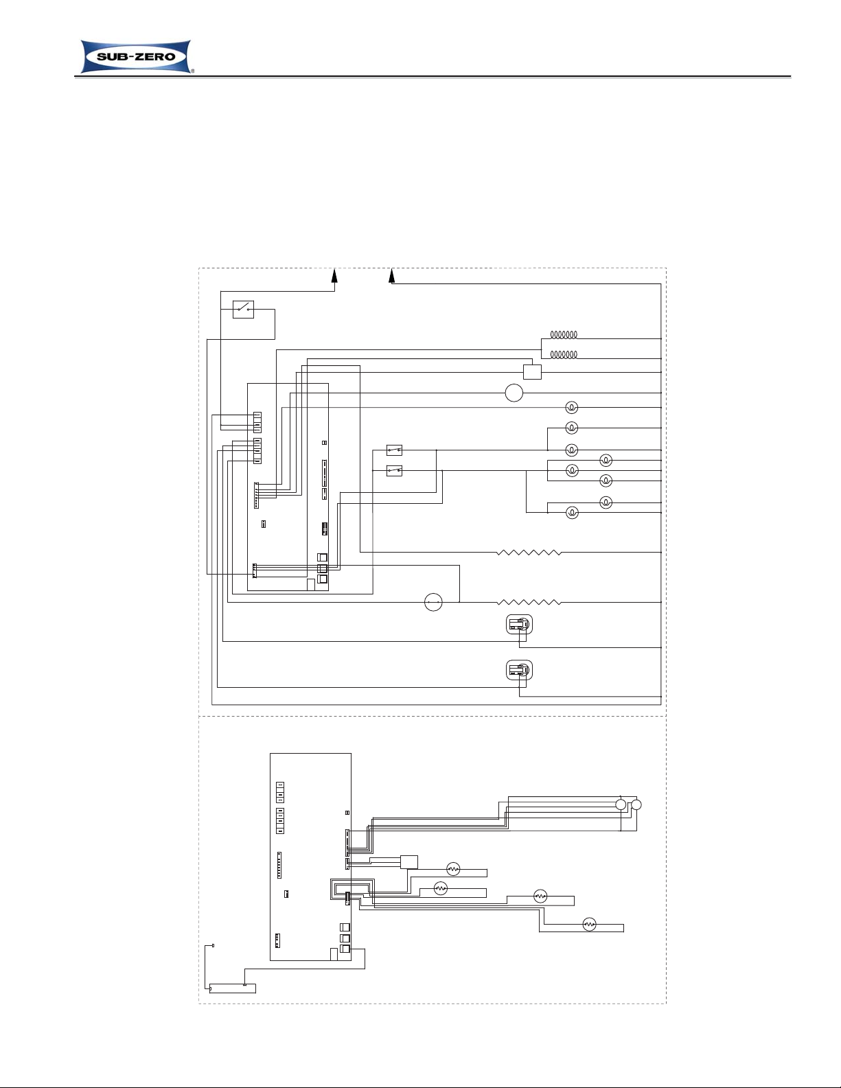
Figure 3-1. Electronic Control System Overview (BI-36UG Wiring Schematic)
115 VOLTS
60 CYCLES
L1
NEUTRAL
N.O.
WATER FILTER SWITCH
P16
MAIN
CONTROL
BOARD
P1
3
P14
L1
L1
NEUTRAL
1164
P2
P15
85
P3
P6
P5
P6
P9
P8
P7
P18
DEFROST HTR
COMP2
COMP1
MAIN LIGHTS
N.C.
N.C.
FZ DOOR SWITCH
REF DOOR SWITCH
ISOLATION VALVE
660 Ω
WATER VALVE
160 Ω
M
IM
CONDENSER FAN MOTOR
CRISPER LIGHTS
REF LIGHTS
AIR FILTER LIGHT
FREEZER LIGHTS
FILL-TUBE HEATER
2300-2900 Ω
DEF HEATER
27.9-30.9 Ω
DEFROST TERMINATOR
REFRIGERATOR COMPRESSOR
STARTING RELAY
FREEZER COMPRESSOR
STARTING RELAY
PURPLE
WHITE
WHITE/BLUE
WHITE/BLUE
BLUE
WHITE
PURPLE
GRAY
RED
PINK
YELLOW
BLACK
RED
WHITE/BLUE
TAN
BLUE
ORANGE
YELLOW
YELLOW
ORANGE/BLACK
GRAY/WHITE
ORANGE/BLACK
WHITE
RED/WHITE
WHITE/RED
TAN
PINK
GRAY
ORANGE
WHITE
WHITE
WHITE
WHITE
WHITE
WHITE
WHITE
WHITE
WHITE
WHITE
WHITE
WHITE
WHITE
WHITE
TAN/WHITE
TAN/WHITE
BROWN
YELLOW
WHITE
REF
EVAPORATOR FAN
FREEZER
EVAPORATOR FAN
M
M
FLOW
METER
THERMISTER FREEZER EVAP
THERMISTER FREEZER CABINET
THERMISTER REF CABINET
THERMISTER REF EVAP
BROWN
BLACK/WHITE
WHITE/BLACK
BLUE
BROWN
BLUE
BROWN
YELLOW
RED
YELLOW/BROWN
BLUE/WHITE
BROWN
BLUE
BLUE
BROWN
BLUE
WHITE
MAIN CONTROL
BOARD
16
1
17
1
P18
3
P6
P15
P16
85
P14
1164
P6
P9
P8 P7
P5
P2
P3
P1
DEFROST HTR
COMP2
COMP1
MAIN LIGHTS
L1
NEUTRAL
L1
EXERNAL
DEVICE
KEYPAD
LOW VOLTAGE
HIGH VOLTAGE
ELECTRONIC CONTROL SYSTEM OVERVIEW
Figure 3-1 is the wiring schematic for the model BI-36UG showing the components of the electronic control system.
• Manual input operations are performed at the Control Panel Assembly (Keypad).
• Monitoring, regulating and controlling functions take place at the Main Control Board.
• Temperatures, icons and function/diagnostic codes are displayed in the LCD (part of Keypad).
The entire electronic control system is described in greater detail on the following pages.
NOTE: For more detailed electrical diagrams refer to the wiring diagram and schematic supplied with the appliance.
Previous Page
Next Page
Main Menu
Built-In Series Menu
Built-In Series Menu
Previous Page
Main Menu
Table of Contents
Next Page
Page 3
Electronic Control System
3-4
#7019014 - Revision A - October, 2010
Built-In (BI) Series
Built-In (BI) Series
MAIN CONTROL
BOARD
P18
3
P6
P15
P16
85
P14
1164
P6
P9
P8 P7
P5
P2
P3
P1
DEFROST HTR
COMP2
COMP1
MAIN LIGHTSL1NEUTRAL
L1
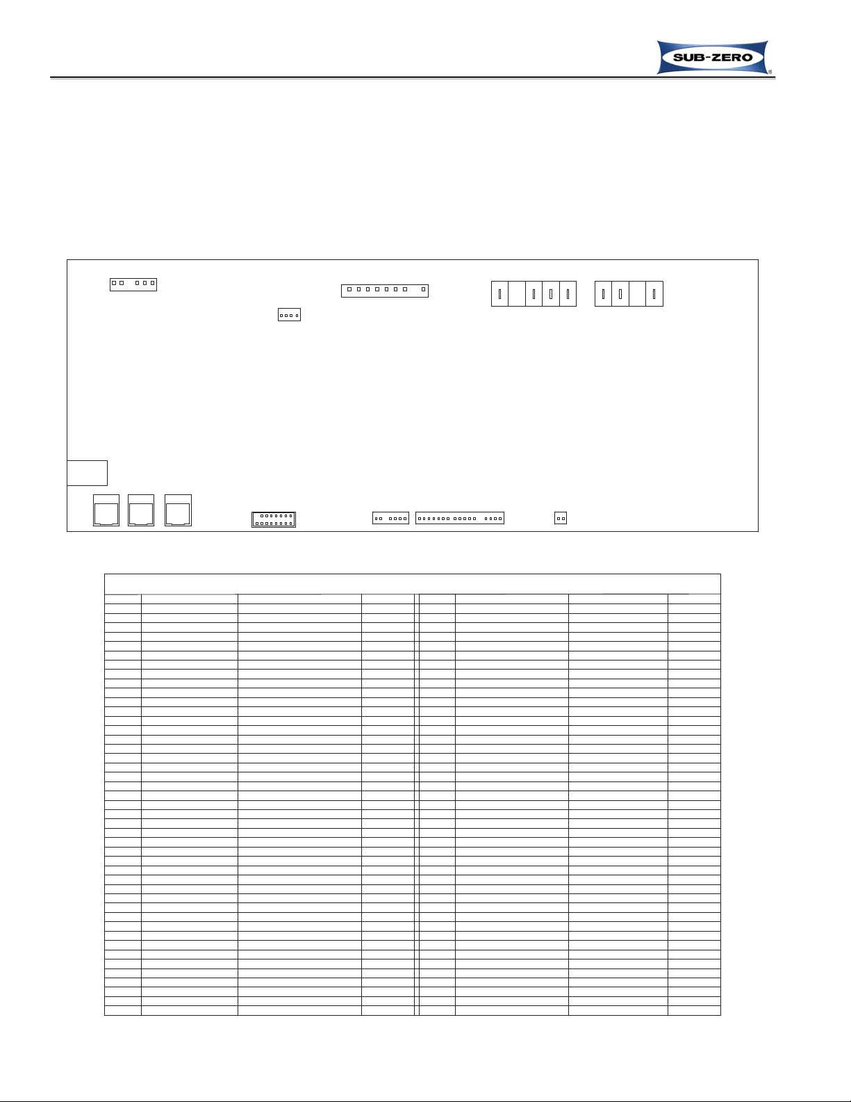
Figure 3-2. Control Board Layout
Figure 3-3. Control Board Summary Table
CONTROL BOARD LAYOUT AND SUMMARY TABLE
The electrical connection points on the main control board are labeled alphanumerically (See Figure 3-2). These
labels correspond with the alphanumeric control board summary table, located on wiring diagrams (See Figure 3-3).
By referencing the summary table, it is possible to identify which components are connected at which connection
points on the main control board.
NOTE: All components on control board are non-replaceable. If problems with control board are identified, the
complete control board must be replaced.
P16-5
P16-6
P16-7
P16-8
P16-9
P18-1
P18-2
P18-3
P18-4
P18-5
P18-6
P14-5
P14-6
P14-1
P14-2
P14-3
P14-4
P15-8
P15-7
P15-6
P15-5
P15-4
P15-3
P15-1
P15-2
CIRCUIT
P16-1
P16-2
P16-3
P16-4
ICE MAKER ACCESSORIES
WATER VALVE INPUT
REFRIGERATOR DOOR INPUT
WATER FILTER RESET SWITCH
FREEZER DOOR INPUT
UNUSED
ICE MAKER
CONDENSER FAN
AIR FILTER LIGHT
UNUSED
REF BI-METAL
UNUSED
UNUSED
ICE MAKER WATER VALVE
120 VOLT CIRCUITS
POWER IN (L1)
UNUSED
POWER IN (L1)
NEUTRAL
UNUSED
UNUSED
DEFROST HEATER
MAIN LIGHTS
UNUSED
COMPRESSOR #2
COMPRESSOR #1
UNUSED
UNUSED
UNUSED
WATER VALVE
DESCRIPTION
POWERS FILL TUBE AND ACCESSORIES
---
---
SENSES IF REF DOOR IS OPEN
SENSES WATER VALVE ACTIVATION
SENSES WHEN DEF HEATER SHUTS OFF
SENSES IF FREEZER DOOR IS OPEN
POWERS ICE MAKER
CONDENSER FAN
AIR FILTER LIGHT
SENSES WATER FILTER
UNUSED
UNUSED
POWER INTO BOARD
NEUTRAL INTO BOARD
POWER INTO BOARD
POWERS MAIN LIGHTS
POWERS COMPRESSOR
POWERS REF COMPRESSOR
POWERS OFF HEATER
POWERS WATER VALVE
POWERS IM WATER VALVE
UNUSED
UNUSED
UNUSED
UNUSED
UNUSED
UNUSED
UNUSED
FUNCTION
WHITE/BLUE
ORANGE/RED
GRAY/WHITE
ORANGE/BLACK
-
PINK
WHITE/RED
RED
TAN
-
ORANGE
BLACK
-
-
WHITE
-
BLACK
BLUE
YELLOW
PURPLE
GRA
Y
-
-
-
-
COLOR
---
-
--
TAN/WHITE
EVAPORATOR FAN RETURN
CRISPER LIGHT POWER
CRISPER LIGHT RETURN
AIR FILTER FAN OUTPUT
AIR FILTER FAN RETURN
AIR FILTER LIGHT OUTPUT
AIR FILTER LIGHT RETURN
PWM DRIVE OUTPUT
PWM DRIVE OUTPUT
EVAPORATOR FAN POWER
TACHOMETER INPUT
TACHOMETER INPUT
WATER FLOW SENSOR INPUT
FLOW METER POWER
FLOW METER RETURN
---
---
SENSES TEMPERATURE
SENSES TEMPERATURE
SENSES TEMPERATURE
SENSES TEMPERATURE
---
---
SENSES TEMPERATURE
SENSES TEMPERATURE
SENSES TEMPERATURE
SENSES TEMPERATURE
---
---
---
---
---
---
CRISPER LIGHT 12 VDC POWER
CRISPER LIGHT GROUND RETURN
AIR FILTER LIGHT
AIR FILTER LIGHT
FREEZER EVAPORATOR FAN
REF EVAPORATOR FAN
EVAPORATOR FAN 12 VDC POWER
FREEZER EVAPORATOR FAN
LOW VOLTAGE CIRCUITS
REF EVAPORATOR FAN
UNUSED
FLOW METER 12V DC POWER
UNUSED
REFRIGERATOR EVAPORATOR
FREEZER CABINET
FREEZER EVAPORATOR
UNUSED
UNUSED
FREEZER EVAPORATOR
FREEZER CABINET
UNUSED
REFRIGERATOR EVAPORATOR
UNUSED
THERMISTER CIRCUITS
EVAPORATOR FAN GROUND RETURN
FLOW METER
P3-3
P3-7
P3-6
P3-4
P3-5
P5-9
P5-8
P5-7
P5-6
P5-5
P5-16
P5-15
P5-14
P5-13
P5-12
P5-11
P5-10
P5-4
P5-3
P5-2
P5-1
CIRCUIT
UNUSED
FLOW METER
UNUSED
UNUSED
UNUSED
REF CABINET
REF CABINET
UNUSED
UNUSED
DESCRIPTION
P2-1
P2-2
P2-3
P2-4
P2-5
P2-6
P2-7
P2-8
P2-9
P2-10
P2-1
1
P2-12
P2-13
P2-14
P2-15
CIRCUIT
P2-16
P2-17
CIRCUIT
P3-2
P3-1
UNUSED
AIR FILTER FAN
AIR FILTER FAN
UNUSED
DESCRIPTION
UNUSED
DESCRIPTION
UNUSED
UNUSED
FUNCTION
UNUSED
UNUSED
FUNCTION
UNUSED
FUNCTION
WHITE/BROWN
YELLOW/BROWN
WHITE/BLACK
-
BROWN
BLACK/WHITE
BROWN
BLUE/BLACK
BROWN
BLUE
BROWN
BLUE/WHITE
BROWN
BLUE/YELLOW
BROWN
BLUE/ORANGE
BROWN
BLUE/RED
----
---
----
----
COLOR
-
-
-
-
-
-
WHITE
RED/BLACK
YELLOW
RED
BLUE/WHITE
COLOR
-
-
-
BLUE
COLOR
UNUSED
UNUSED
-
UNUSED
UNUSED
-
-
S x S CONTROL BOARD SUMMARY
Previous Page
Next Page
Main Menu
Previous Page
Next Page
Main Menu
Table of Contents
Built-In Series Menu
Built-In Series Menu
Page 4
Electronic Control System
3-5
#7019014 - Revision A - October, 2010
Built-In (BI) Series
Built-In (BI) Series
PURE AIR WARMER COLDER WARMER COLDER ALARM POWER MAX ICE ICE MAKER LIGHTS
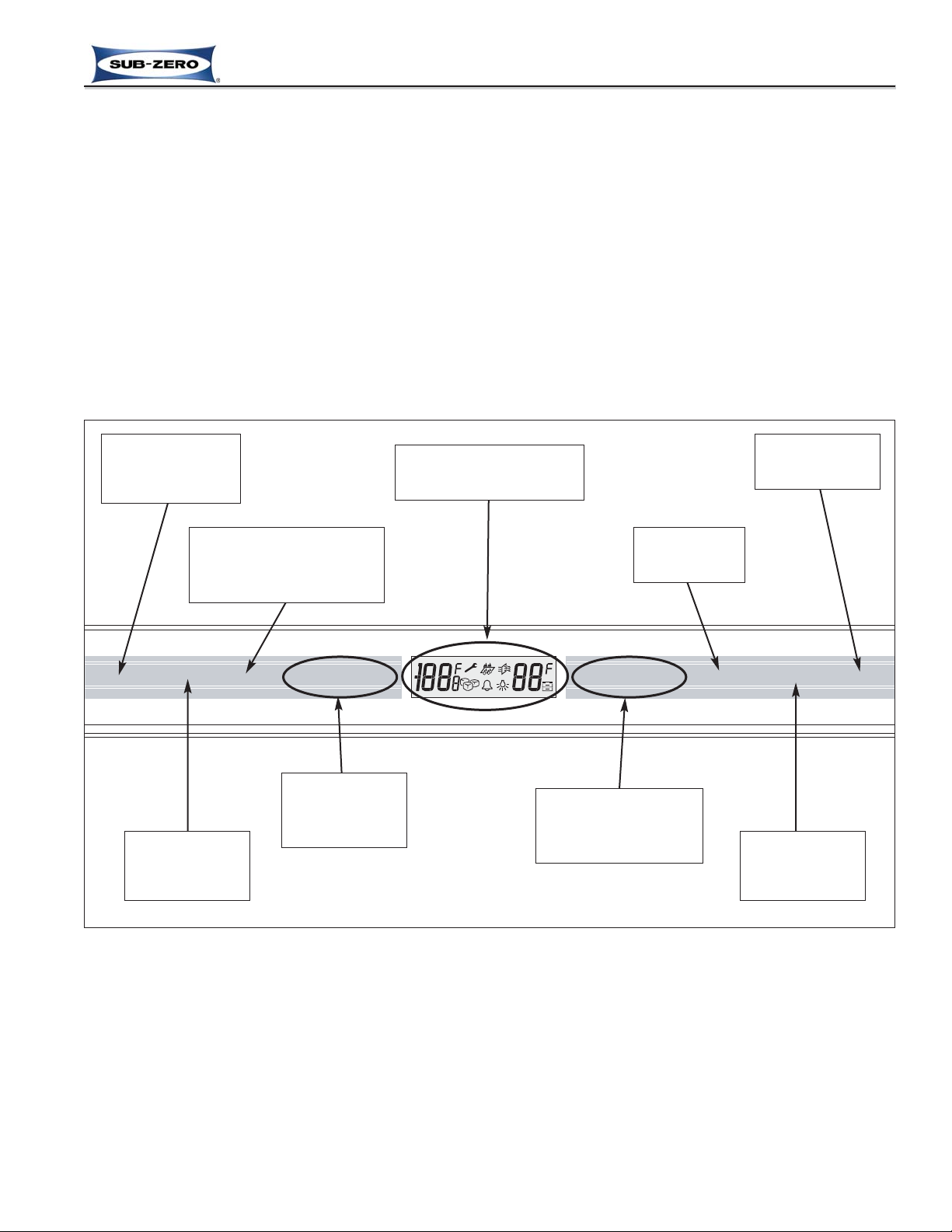
CONTROL PANEL LAYOUT (AKA USER INTERFACE MODULE)
Figure 3-4 below shows the layout of the control panel assembly.
NOTES:
• Not all keys are present on all models:
- If the unit does not have a glass refrigerator door, the control panel will not have the accent LIGHTS on/off key.
- The control panel in an all-refrigerator model does not have the freezer zone COLDER and WARMER keys, nor
the ICE MAKER and MAX ICE keys.
- The control panel in an all-freezer model does not have the refrigerator zone COLDER and WARMER keys, nor
the PURE AIR key.
• The control panel keys are “capacitance touch sensitive”, so even though the words “press” is used throughout
this section to indicate what to do to the keys, they actually only need to be “touched” to operate.
• Whenever a key is touched the electronic control will emit a beep.
Figure 3-4. Control Panel Layout
UNIT / POWER
ON/OFF KEY
DOOR AJAR
ALARM ON/OFF
KEY
ACCENT LIGHTS
ON/OFF KEY
units with glass
doors only
ICE MAKER
SYSTEM ON/OFF
KEY
FREEZER ZONE
SET-POINT
ADJUSTMENT
KEYS
LCD
(Liquid Crystal ‘Display)
MAXIMUM ICE
PRODUCTION ON/OFF KEY
speeds ice production
by up to 40%
REFRIGERATOR ZONE
SET-POINT
ADJUSTMENT
KEYS
AIR PURIFIER
ON/OFF KEY
Previous Page
Next Page
Main Menu
Built-In Series Menu
Built-In Series Menu
Previous Page
Main Menu
Table of Contents
Next Page
Page 5

Electronic Control System
3-6
#7019014 - Revision A - October, 2010
Built-In (BI) Series
Built-In (BI) Series
PURE AIR WARMER COLDER WARMER COLDER ALARM POWER MAX ICE ICE MAKER LIGHTS
Figure 3-5. Power Supplied to Unit, but Unit in OFF Mode
BASIC ELECTRONIC CONTROL INPUT OPERATIONS
The following pages describe the basic input operations performed at the control panel (switching unit ON and OFF;
adjusting set-point (temperature adjustment); switching ice maker system ON and OFF; activate and deactivate
maximize ice production feature; enabling and disabling door ajar alarm feature; activate and deactivate air purification feature; and in models with glass doors only, switching accent lighting system ON and OFF). Please note that
though possible to display temperatures in Fahrenheit or Celsius, in most cases Fahrenheit readings are shown in
this manual.
Unit ON/OFF
All units are shipped in OFF Mode. When electricity is supplied to the appliance, a short power up diagnostics test
is initiated where the lights are energized, “- -” (double-dashes) appear in the LCD, followed by the model code, then
all components are switched OFF and the word “OFF” appears in the LCD (See Figure 3-5). By pressing the
POWER key for one (1) second, electricity is allowed past the control board to the rest of the unit (See Figure 3-6),
indicated by two audible beeps, the lights energizing and temperature readings appearing in the LCD.
NOTES:
• Whenever the unit is switched OFF using the POWER key, the word “OFF” will be visible in the LCD as long as
there is electricity supplied to the appliance.
• Whenever the unit is switched ON using the POWER key, the model code will appear in the LCD for approximately two (2) seconds, then temperature readings will appear.
• If the unit experiences any problems during the power up diagnostic test, then the appropriate Fault Codes will be
logged.
PURE AIR WARMER COLDER WARMER COLDER ALARM POWER MAX ICE ICE MAKER LIGHTS
Figure 3-6. Switching Unit ON (or OFF) - Press POWER Key, Actual Temperatures will be Displayed
WHEN IN “OFF” MODE, AC LINE VOLTAGE IS STILL PRESENT AT CONTROL BOARD!
Previous Page
Next Page
Main Menu
Built-In Series Menu
Built-In Series Menu
Previous Page
Main Menu
Table of Contents
Next Page
Page 6
Electronic Control System
3-7
#7019014 - Revision A - October, 2010
Built-In (BI) Series
Built-In (BI) Series
Adjusting Set-Point (Temperature Adjustment)
To adjust set-points, press the appropriate WARMER or COLDER key on control panel in multiple key strokes
until
the desired set-point is achieved (See Figure 3-7). Each key stroke equals a one degree change and is accompanied by an audible beep. When the desired set-point is reached and the keys are no longer being pressed, the setpoint will flash ON and OFF at two (2) second intervals for ten (10) seconds, then the current zone temperature will
be displayed.
NOTES:
• During initial pull-down the real-time compartment temperatures will be displayed, then once set-point tempera-
tures are achieved, the temperature shown in the LCD can change by no more than one (1) degree per minute.
• The temperature range in a freezer zone is -5°F (-20°C) to +5°F (-15°C).
• The temperature range in a refrigerator zone is +34°F (+1°C) to +45°F (+7°C).
• Initial factory set-points are 0°F (-18°C) in a freezer zone and 38°F (3°C) in a refrigerator zone.
• The initial stroke of the WARMER or COLDER key will change the previous set-point by one degree.
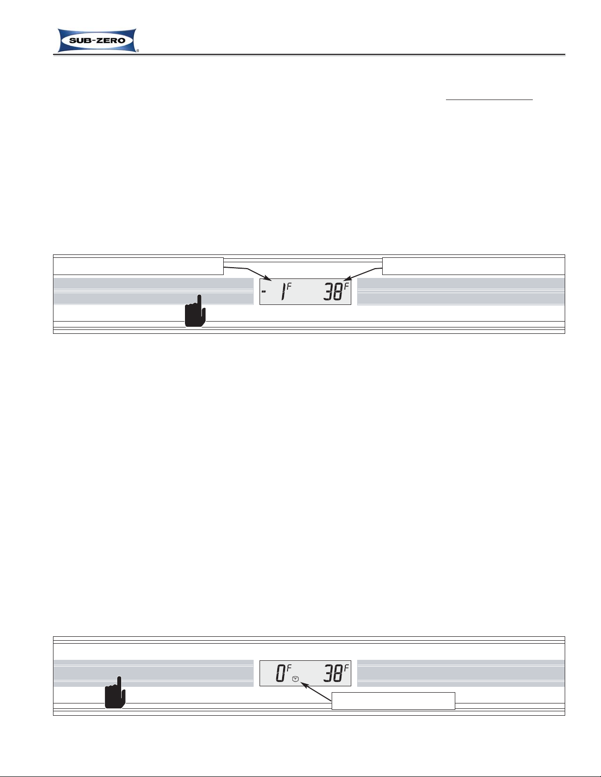
PURE AIR WARMER COLDER WARMER COLDER ALARM POWER MAX ICE ICE MAKER LIGHTS
Figure 3-7. Adjusting Set-Point - Press Desired WARMER or COLDER Key In Multiple Key Strokes
Freezer Set-Point/Temperature Display
Refrigerator Set-Point/Temperature Display
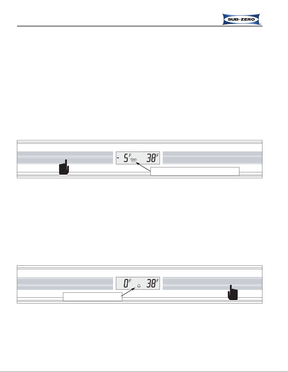
Ice Maker System ON/OFF
All units are shipped with the ice maker system switched OFF. By pressing the ICE MAKER key on the control
panel, power is allowed to the ice maker system and the single ice cube icon appears in the LCD (See Figure 3-8).
To switch the ice maker system OFF, press the ICE MAKER key again and the single ice cube icon disappears.
NOTES:
• Power to the freezer lights is monitored to help control icemaker operation. If the freezer door is open, power to
the ice maker system is interrupted, unless the icemaker is filling with water at that time. After the door is closed,
power is not allowed to the ice maker system for an additional three (3) minutes, unless the Maximum Ice
Production feature has been initiated.
• The ice maker system will continue to produce ice if the ice bucket is not in the correct position. However, to help
prevent the ice maker system from filling the freezer with ice, the electronic control will not allow twenty (20) consecutive ice harvests between any two door openings.
• To allow ice to freeze fully and reduce effects of low water pressure, power to the ice maker system is interrupted
for forty-five (45) minutes after each ice harvest. This can be bypassed for service purposes by switching the icemaker system OFF, then back ON with the ICE MAKER key.
• The fill tube heater is energized 100% of the time whenever the ice maker system is ON.
• When in Sabbath Mode, the icemaker system is disabled. Sabbath Mode will be explained later.
• The ice maker system is disabled whenever the water filter or water filter plug is removed.
Figure 3-8. Switch Ice Maker System ON or OFF - Press ICE MAKER Key, Single Ice Cube Appears when ON
PURE AIRWARMERCOLDER WARMERCOLDER ALARM POWERMAX ICEICE MAKERLIGHTS
Ice Maker System is ON
Previous Page
Next Page
Main Menu
Built-In Series Menu
Built-In Series Menu
Previous Page
Main Menu
Table of Contents
Next Page
Page 7
Electronic Control System
3-8
#7019014 - Revision A - October, 2010
Built-In (BI) Series
Built-In (BI) Series
Figure 3-10. Switching Door Ajar Alarm ON or OFF - Press ALARM Key, Bell Appears when Activated
Door Ajar Alarm Feature ON/OFF
All BI Series units are equipped with a door ajar alarm feature. To enable the door ajar alarm, press the ALARM key
on the control panel and the bell icon will appear in the LCD indicating the alarm is enabled (See Figure 3-10). With
the alarm enabled, the bell icon will flash and an audible alarm will chime at two (2) second intervals whenever a
door is left open for more then thirty or sixty (30 or 60) seconds, depending on vintage. To disable the door ajar
alarm, press the ALARM key again and the bell icon disappears from the LCD.
Maximize Ice Production Feature
These appliances are equipped with a feature that can boost ice production up to 40% above normal. By pressing
the MAX ICE key on the control panel, the ice maker system is switched ON (if OFF); multiple ice cube icons appear
in the LCD (See Figure 3-9); the freezer set-point is automatically set to -5°F (-21°C) for twenty-four (24) hours, and
the freezer evaporator fan is switched to 100% run for twenty-four (24) hours, switching off only when the door is
opened.
After twenty-four (24) hours, the freezer set-point reverts to the last manually input set-point, the freezer evaporator
fan resumes its normal operation (cycling with the compressor); and two of the three ice cube icons disappear from
the LCD, indicating normal ice production has resumed.
NOTES:
• When the maximize ice production feature is active, power to the icemaker system is NOT interrupted after ice
harvest, so the icemaker will initiate a harvest as soon as the thermostat reaches 10°F (-12°C).
• Switching the unit OFF, then back ON with the POWER key, or pressing the MAX ICE key during the twenty-four
(24) hour production period will switch the maximize ice production feature OFF.
• When in Sabbath Mode, the icemaker system is disabled. Sabbath Mode will be explained later.
• The ice maker system is disabled whenever the water filter or water filter plug is removed.
Figure 3-9. Maximize Ice Production Feature ON or OFF - Press MAX ICE Key,
Multiple Ice Cubes Appear when Activated
PURE AIRWARMERCOLDER WARMERCOLDER ALARM POWERMAX ICEICE MAKERLIGHTS
Maximize Ice Production Feature Activated
PURE AIR WARMER COLDER WARMER COLDER ALARM POWER MAX ICE ICE MAKER LIGHTS
Alarm Feature is ON
Previous Page
Next Page
Main Menu
Built-In Series Menu
Built-In Series Menu
Previous Page
Main Menu
Table of Contents
Next Page
Page 8
Electronic Control System
3-9
#7019014 - Revision A - October, 2010
Built-In (BI) Series
Built-In (BI) Series
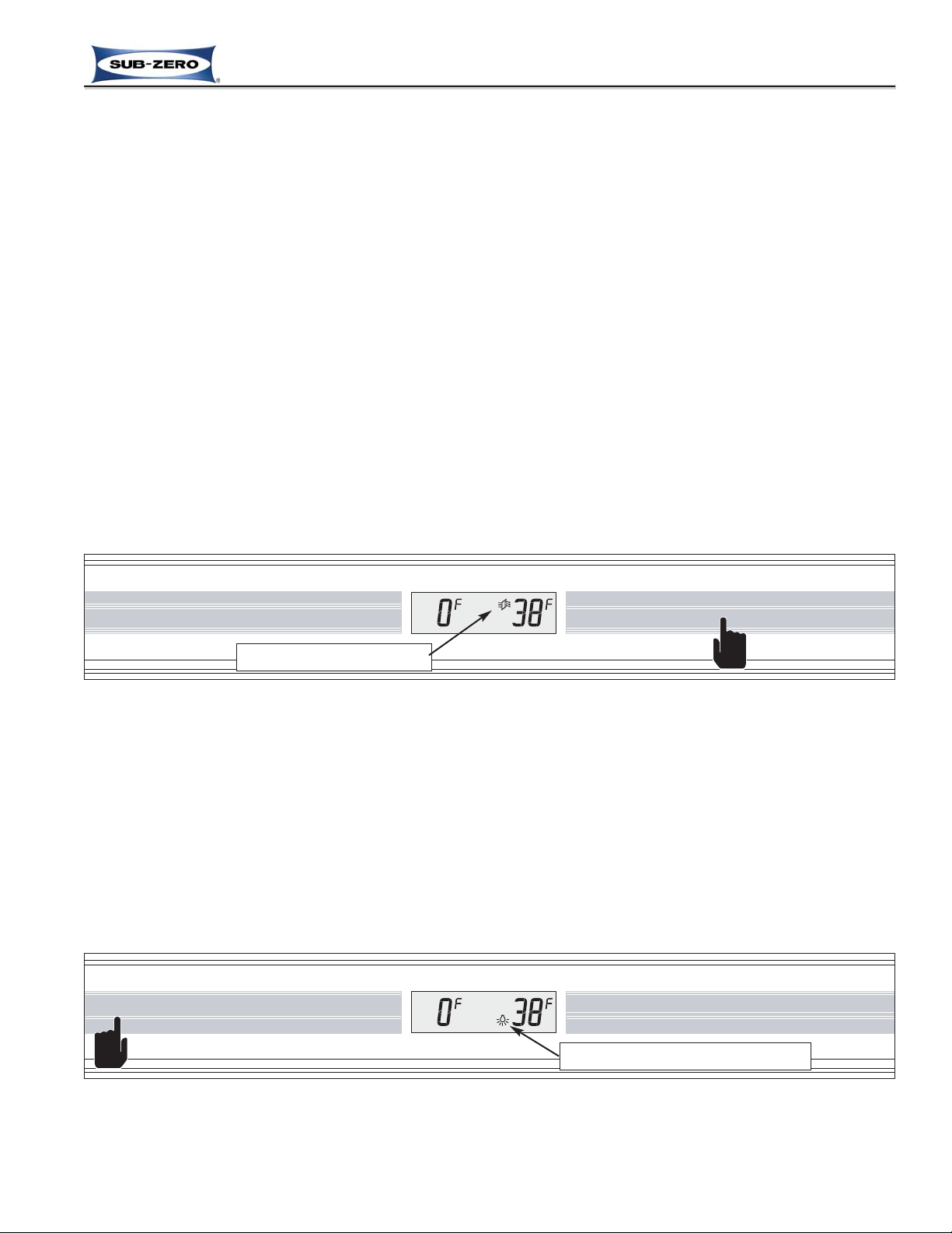
Accent Lighting System ON/OFF (Models Produced with Glass Doors Only)
Models produced with glass refrigerator doors are equipped with an accent lighting system in the refrigerator compartment. To energize the accent lighting system, press the LIGHTS key, and the bulb icon will appear in the LCD
indicating the accent lights are enabled (See Figure 3-12). With the accent lighting system energized, the accent
LED strip will be energized and stay illuminated when the door is closed. To disable the accent lights, press the
LIGHTS key again.
Figure 3-12. Accent Lighting System ON or OFF - Press the LIGHT Key, Bulb Appears when Activated
PURE AIR WARMER COLDER WARMER COLDER ALARM POWER MAX ICE ICE MAKER LIGHTS
Accent Lighting System is Activated
Air Purification Feature ON/OFF
An air purification feature has been incorporated into these appliances to remove bacteria and ethylene gas (byproducts of ripening fruits and vegetables). The two main parts of this air purifier are a replaceable cartridge consisting of a small light and a filter medium, and a small low DC Voltage fan below the cartridge. The fan drives the
refrigerator compartment air through the cartridge, over the light induced chemical filtering system which converts
these harmful airborne food storage by-products into water vapor and carbon dioxide. Please note that this is not
intended to be an “air deodorizer”, but rather a devise that helps to preserve foods for longer storage life by removing these food storage by-products.
To activate the air purification feature, press the PURE AIR key, and the Pure Air Icon appears in the LCD indicating
the air purification feature has been activated (See Figure 3-11). When activated, the UV light in the filter cartridge
and the fan motor under the cartridge are energized 100% of the time, unless the refrigerator door is opened or the
unit is in Showroom Mode.
After approximately eight-thousand (8000) hours of use, the Pure Air Icon will flash, indicating it is time to change
the air purifier cartridge. To stop the Pure Air Icon from flashing and reset the timer after the cartridge is replaced,
the PURE AIR key must be pressed and held for five (5) seconds.
NOTES:
• If the unit is in Sabbath Mode, the air purifier fan will not switch OFF when the refrigerator door is opened.
• If in Showroom Mode, the air purifier will operate for thirty (30) seconds whenever the door is open or the PURE
AIR key is pressed. Pressing the PURE AIR key again will force the air purifier ON for another thirty (30) seconds.
• If the light bulb in the cartridge should fail, the Pure Air Icon will flash and the appropriate fault code will be logged.
Figure 3-11. Air Purification ON or OFF - Press PURE AIR Key, Pure Air Icon Appears when ON
PURE AIR WARMER COLDER WARMER COLDER ALARM POWER MAX ICE ICE MAKER LIGHTS
Air Purifier Feature is ON
Previous Page
Next Page
Main Menu
Built-In Series Menu
Built-In Series Menu
Previous Page
Main Menu
Table of Contents
Next Page
Page 9
Electronic Control System
3-10
#7019014 - Revision A - October, 2010
Built-In (BI) Series
Built-In (BI) Series
UNIQUE ELECTRONIC CONTROL INPUT OPERATIONS
The following pages illustrate unique customer input operations performed at the control panel. The input operations
described are: Temperature Unit Selection Mode, Contrast Adjust Mode, Tone Adjust Mode, Showroom Mode,
Sabbath Mode, Manual Zone Disable and Manual Freezer Evaporator Defrost.
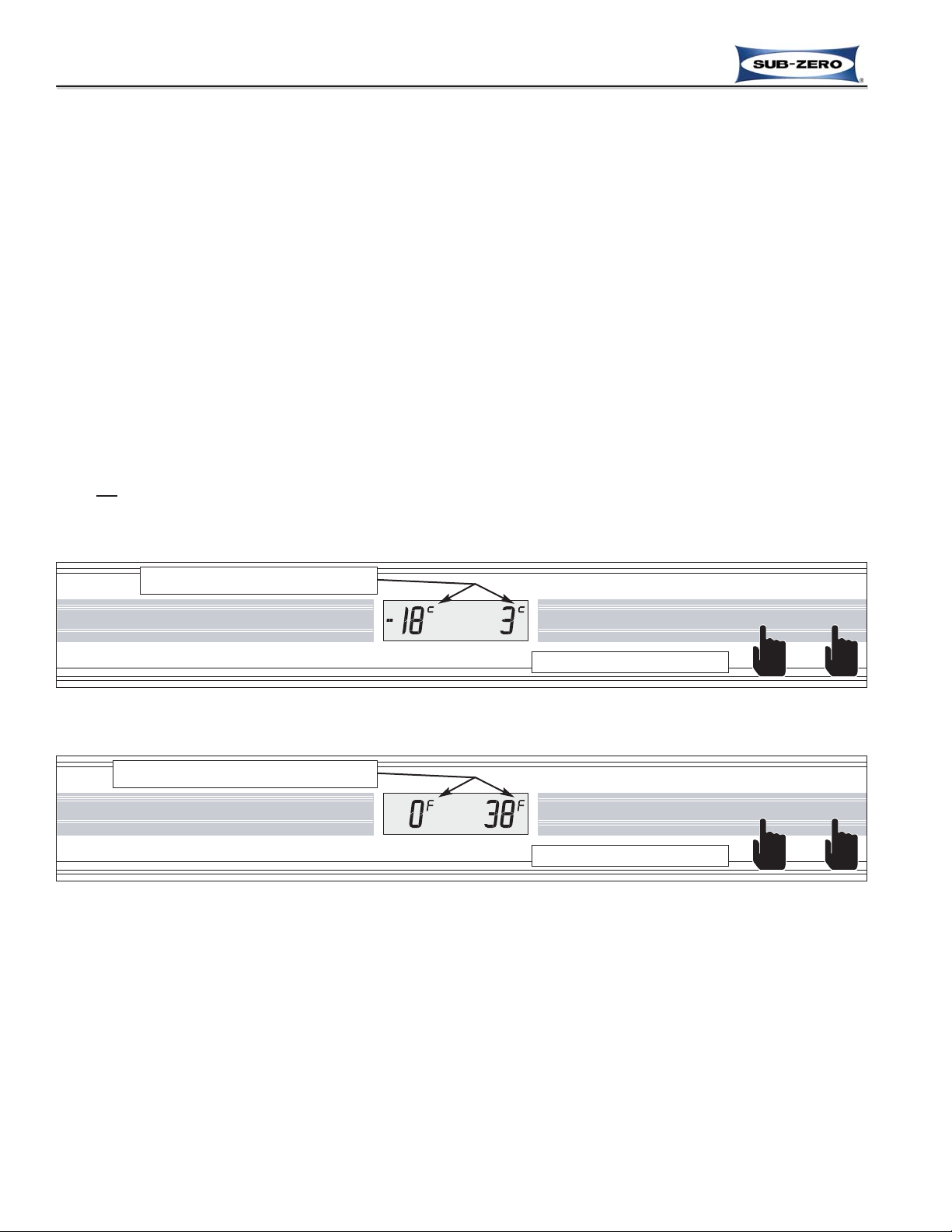
Temperature Units Selection Mode (Selecting Degrees Fahrenheit or Degrees Celsius Display)
The appliance is initially set to display temperatures in Fahrenheit temperature units of measure, indicated by the “F”
at the upper right of the temperature readings in the LCD. This can be changed so Celsius units of measure are displayed by initiating Temperature Units Selection Mode.
NOTE: Temperature Units Selection Mode must be initiated within the first (1) minute after switching the unit ON.
To convert Fahrenheit (°F) temperature units of measure to Celsius (°C) within the first minute after switching the
unit ON, press and hold the ALARM key and the POWER key simultaneously for five (5) seconds, then release the
keys (See Figure 3-13); a “c“ will appear at the upper right of the temperature readings in the LCD, indicating that
temperatures will now be displayed in Celsius units of measure. Please note that changing from Celsius temperature units of measure to Fahrenheit is the same procedure (See Figure 3-14).
NOTES:
• Do not
press and hold the POWER key first, that will simply switch the unit OFF.
• Temperature Units Selection Mode will end ten (10) seconds after the last key stroke, or the ALARM key can be
pressed to exit this mode before the ten (10) seconds has elapsed.
PURE AIR WARMER COLDER WARMER COLDER ALARM POWER MAX ICE ICE MAKER LIGHTS
Figure 3-13. Converting Temperature Units of Measure to °C (within first minute after switching unit ON) -
Press and Hold ALARM Key and POWER Key for 5 Seconds
Press and hold for 5 seconds
Figure 3-14. Converting Temperature Units of Measure to °F (within first minute after switching unit ON) -
Press and Hold ALARM Key and POWER Key for 5 Seconds
Indicates Celsius Units of Measure
PURE AIR WARMER COLDER WARMER COLDER ALARM POWER MAX ICE ICE MAKER LIGHTS
Press and hold for 5 seconds
Indicates Fahrenheit Units of Measure
Previous Page
Next Page
Main Menu
Built-In Series Menu
Built-In Series Menu
Previous Page
Main Menu
Table of Contents
Next Page
Page 10
Electronic Control System
3-11
#7019014 - Revision A - October, 2010
Built-In (BI) Series
Built-In (BI) Series
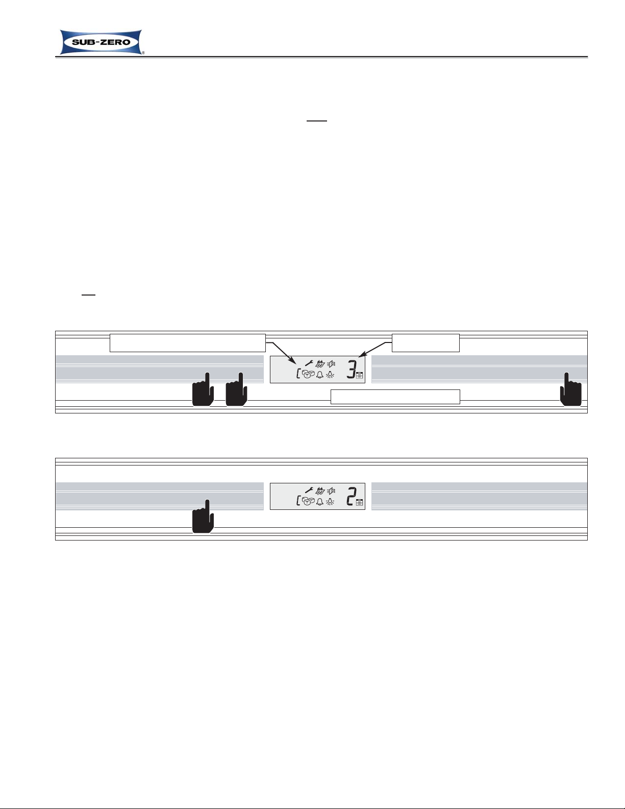
Contrast Adjust Mode (Adjusting the LCD Contrast Level)
The contrast level of the LCD can be manually adjusted to one of five levels through Contrast Adjust mode.
NOTE: Contrast Adjust Mode can be initiated anytime af
ter the first (1) minute of switching the unit ON.
To adjust the LCD contrast level anytime after the first minute of switching the unit ON, press and hold either set of
COLDER and WARMER keys and the POWER key simultaneously for five (5) seconds, then release the keys (See
Figure 3-15). The letter “C” will appear at the small digit location in the LCD indicating the control is now in Contrast
Adjust Mode and a number 1, 2, 3, 4, or 5 will appear at the right side of the LCD, indicating the last contrast level
setting. Pressing a COLDER key at this time will decrease the number; pressing a WARMER key will increase the
number (See Figure 3-16).
Please note that what is actually happening here is the segments and icons in the LCD are slanting at slightly different angles for each level adjustment. This means that the lower numbers will not always indicate less contrast and
the higher numbers will not always indicate more contrast, as it depends on the line of sight of the user. In fact a tall
person and a short person standing side-by-side during the adjustment may see the contrast level move in totally
opposite directions; one seeing it increase, the other seeing it decrease.
NOTES:
• Do not
press and hold the POWER key first, that will simply switch the unit OFF.
• Contrast Adjust Mode will end ten (10) seconds after the last key stroke, or press ALARM key to exit.
PURE AIR WARMER COLDER WARMER COLDER ALARM POWER MAX ICE ICE MAKER LIGHTS
Figure 3-15. Adjusting LCD Contrast Level (any time after first minute of switching unit ON) -
Press and Hold COLDER, WARMER and POWER Keys for 5 Seconds
Press and hold for 5 seconds
Figure 3-16. Press COLDER or WARMER Key to Change Contrast Level
(Pressing COLDER Shown - Decrease Number)
“C” Indicates Contrast Adjust Mode
Contrast Level
PURE AIR WARMER COLDER WARMER COLDER ALARM POWER MAX ICE ICE MAKER LIGHTS
Previous Page
Next Page
Main Menu
Built-In Series Menu
Built-In Series Menu
Previous Page
Main Menu
Table of Contents
Next Page
Page 11
Electronic Control System
3-12
#7019014 - Revision A - October, 2010
Built-In (BI) Series
Built-In (BI) Series
Tone Adjust Mode (Adjusting the Audible Chime Tone)
The tone of the electronic control audible chime is preset at the factory. This preset level is referred to as the “normal” tone, but it can be manually adjusted down to low, or up to high, for a total of three possible settings. This is
possible through Tone Adjust Mode.
NOTE: Tone Adjust Mode can be initiated anytime af
ter the first (1) minute of switching the unit ON.
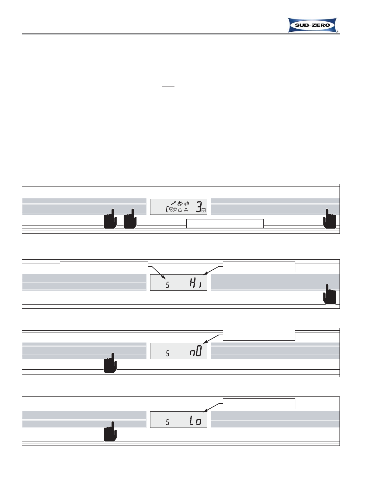
To adjust the chime tone, first initiate Contrast Adjust Mode by pressing and holding either set of COLDER and
WARMER keys and the POWER key simultaneously for five (5) seconds, then release the keys (See Figure 3-17).
While in Contrast Adjust Mode, press the POWER key, and the letter “S” (for “Sound”) will appear at the small digit
location in the LCD indicating the control is now in Tone Adjust Mode. At the right side of the LCD will be the letters
“Hi” (for High), or “nO” (for Normal), or “Lo” (for Low), indicating the last tone setting (See Figure 3-18). Pressing a
COLDER key at this time will decrease the tone setting and the chime will sound in the lower/softer tone; while
pressing a WARMER key will increase the tone setting and the chime will sound in the higher/louder tone (See
Figures 3-19 and 3-20).
NOTES:
• Do not
press and hold the POWER key first, that will simply switch the unit OFF.
• Tone Adjust Mode will end ten (10) seconds after the last key stroke, or press ALARM key to exit.
PURE AIR WARMER COLDER WARMER COLDER ALARM POWER MAX ICE ICE MAKER LIGHTS
Figure 3-17. Adjusting Chime Tone (any time after first minute of switching unit ON) - Initiate Contrast
Adjust Mode First; Press and Hold COLDER, WARMER and POWER Keys for 5 Seconds
Press and hold for 5 seconds
Figure 3-18. While in Contrast Adjust Mode, Press POWER Key to Initiate Tone Adjust Mode
PURE AIR WARMER COLDER WARMER COLDER ALARM POWER MAX ICE ICE MAKER LIGHTS
“S” Indicates Tone Adjust Mode
Tone Level. “Hi” = High
Figure 3-19. Press COLDER Key to Decrease Tone; Press WARMER Key to Increase Tone
PURE AIR WARMER COLDER WARMER COLDER ALARM POWER MAX ICE ICE MAKER LIGHTS
Tone Level. “nO” =Norman
Figure 3-20. Press COLDER Key to Decrease Tone; Press WARMER Key to Increase Tone
PURE AIR WARMER COLDER WARMER COLDER ALARM POWER MAX ICE ICE MAKER LIGHTS
Tone Level. “nO” =Norman
Previous Page
Next Page
Main Menu
Built-In Series Menu
Built-In Series Menu
Previous Page
Main Menu
Table of Contents
Next Page
Page 12
Electronic Control System
3-13
#7019014 - Revision A - October, 2010
Built-In (BI) Series
Built-In (BI) Series
PURE AIR WARMER COLDER WARMER COLDER ALARM POWER MAX ICE ICE MAKER LIGHTS
Showroom Mode
Showroom Mode was incorporated into the electronic control system so that these appliances could be displayed in
a showroom setting. When in Showroom Mode all cooling, defrosting, ice making and dispensing (if applicable)
functions are disabled, but the lighting system and door ajar alarm system remain operational, and the LCD will
show the set-points.
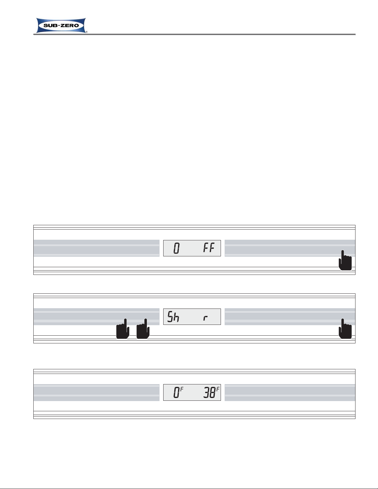
To initiate Showroom Mode, the unit must first be switched OFF using the POWER key (See Figure 3-21). Then,
press and hold either pair of WARMER and COLDER keys, then the POWER key, at which point three (3) beeps will
be emitted and “Sh” and “r” will appear in the LCD for five (5) seconds indicating the appliance is now is showroom
mode (See Figure 3-22). After the initial five seconds, set-points will appear in the LCD (See Figure 3-23).
To return the unit to normal operation, repeat the steps above.
NOTES:
• The air purifier will be energized for thirty (30) seconds any time the door is opened or the PURE AIR key is
pressed.
• The lighting system will be disabled for twenty (20) minutes if the lights stay ON more than 90% of the time in any
given fifteen (15) minutes, or if a compartment thermistor reports a temperature greater than ambient plus thirty
(30) degrees, or if an evaporator thermistor reports a temperature greater than ambient plus twenty (20) degrees.
• For demonstration purposes, the water filter icon can be forced ON during Showroom Mode by pressing the ICE
MAKER key for five (5) seconds. To switch it OFF, press the filter reset button behind the unit grille for five (5)
seconds.
• Units with glass refrigerator doors contain a glass door heater, which is disabled while in Showroom mode.
• Always check set-points after returning unit to normal operation.
Figure 3-22. Then Press and Hold Either Pair of WARMER and COLDER Keys, Then the POWER Key -
“Sh” and “r” appear for 5 Seconds
Figure 3-21. To Enter (or Exit) Showroom Mode, Switch Unit OFF First
PURE AIR WARMER COLDER WARMER COLDER ALARM POWER MAX ICE ICE MAKER LIGHTS
PURE AIR WARMER COLDER WARMER COLDER ALARM POWER MAX ICE ICE MAKER LIGHTS
Figure 3-23. Set-points Appear in LCD 5 seconds after Showroom Mode is Initiated
Previous Page
Next Page
Main Menu
Built-In Series Menu
Built-In Series Menu
Previous Page
Main Menu
Table of Contents
Next Page
Page 13
Electronic Control System
3-14
#7019014 - Revision A - October, 2010
Built-In (BI) Series
Built-In (BI) Series
Figure 3-25. Then Press and Hold POWER Key for 10 seconds
PURE AIR WARMER COLDER WARMER COLDER ALARM POWER MAX ICE ICE MAKER LIGHTS
Sabbath Mode
Sabbath Mode was incorporated into the electronic control system for the observance of certain religious days.
When Sabbath Mode is initiated the lighting systems, ice making system, dispensing system (if applicable), alarm
system and the air purification feature are disabled, plus the letters “SA” and “b” will appear in the LCD.
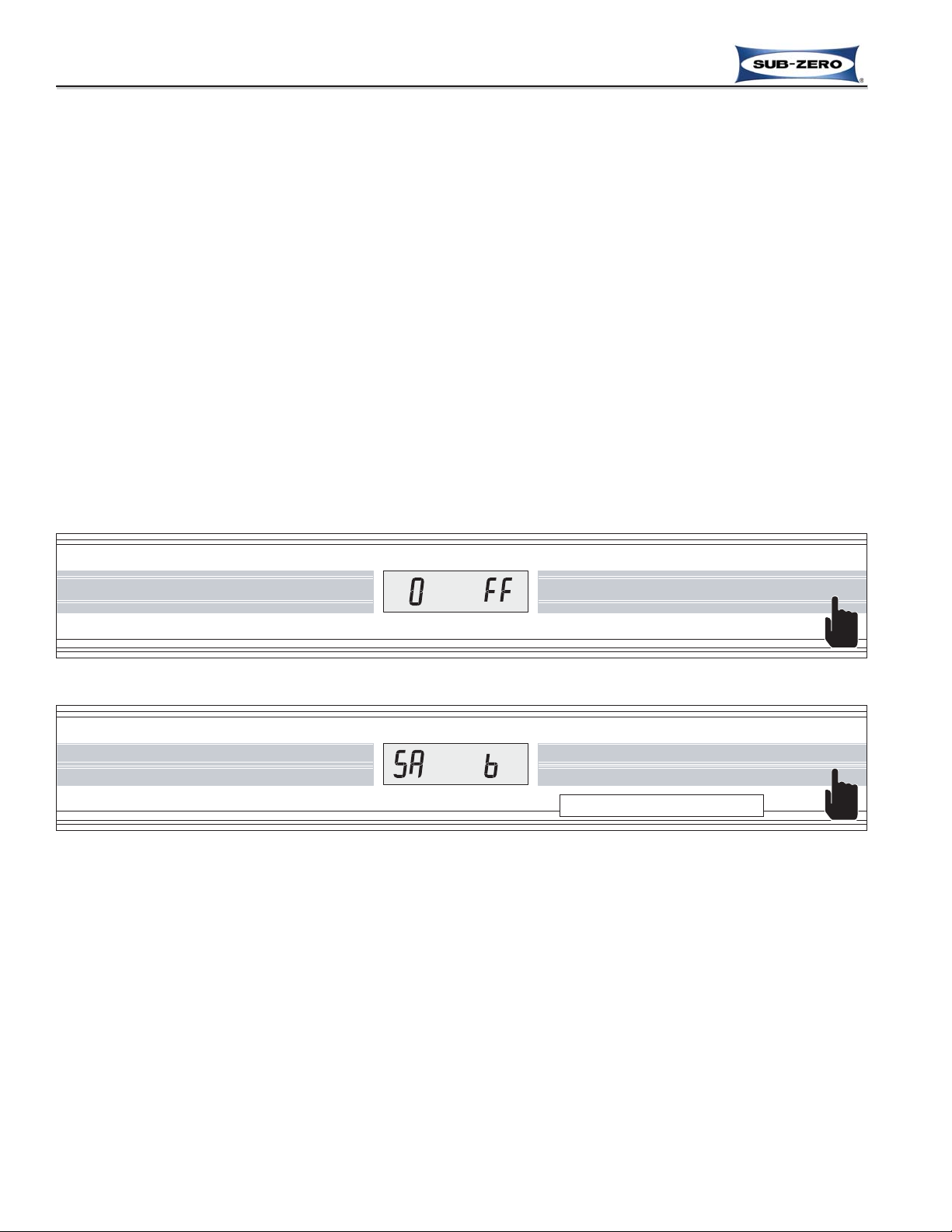
To initiate Sabbath Mode, the unit must first be switched OFF using the POWER key (See Figure 3-24). Then,
press and hold the POWER key for ten (10) seconds, at which time the alarm will chime, and “SA” and “b” will
appear in the LCD (See Figure 3-25).
To return to normal operation, press the POWER key, the lights will be energized accompanied by two beeps and
current zone temperature will appear in the LCD.
NOTES:
• Set-points cannot be changed and manual defrost cannot be initiated.
• The following holds true in accordance with Star-K requirements:
- Freezer defrosting functions will convert to a fixed time base sequence instead of adaptive defrosting, which is
usage based.
- The compartment/zone thermistors will still detect high off-set, which is the determining factor to start the cooling
process, but there will be a random fifteen (15) to twenty-five (25) second delay before cooling begins.
- The “SA” and “b” in the LCD remain energized when the door is closed.
• When Sabbath Mode is exited, the accent lights, door alarm, icemaker and air purification system will return to the
ON or OFF state they were in prior to initiating Sabbath Mode.
Figure 3-24. To Enter Sabbath Mode, Switch Unit OFF First
PURE AIR WARMER COLDER WARMER COLDER ALARM POWER MAX ICE ICE MAKER LIGHTS
Press and hold for 10 seconds
Previous Page
Next Page
Main Menu
Built-In Series Menu
Built-In Series Menu
Previous Page
Main Menu
Table of Contents
Next Page
Page 14
Electronic Control System
3-15
#7019014 - Revision A - October, 2010
Built-In (BI) Series
Built-In (BI) Series
Manual Zone Disable Mode
Manual Zone Disable Mode allows a customer or Service Technician to switch one zone, or “compartment” OFF for
defrosting, interior cleaning, or diagnostic purposes, while allowing the other zones to continue cooling.
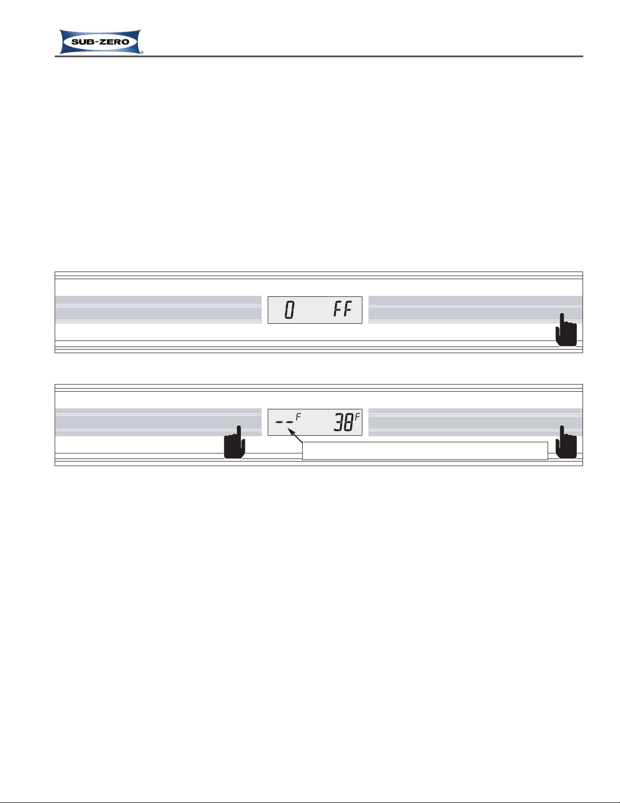
To initiate Manual Zone Disable Mode, the unit must first be switched OFF using the POWER key (See Figure 3-26).
Now, press and hold the WARMER key for the zone being disabled, then the POWER key, then release both keys,
at which time “- -” (double-dashes) will appear in place of temperature readings for the chosen zone (See Figure 3-
27).
To return the disabled zone to operational state, repeat the steps above.
NOTE:
• If switched OFF then back ON, the electronic control stores this mode-set in non-volatile memory, so the disabled
zone will remain disabled until the proper key sequence is performed to reenable the zone.
• The alarm system for the disabled zone is inactive during this mode.
• Always check set-points after returning unit to normal operation.
Figure 3-27. Then Press and Desired Zone WARMER Key along with the POWER Key
PURE AIR WARMER COLDER WARMER COLDER ALARM POWER MAX ICE ICE MAKER LIGHTS
Figure 3-26. To Disable a Zone, Switch Unit OFF First by Pressing the POWER Key
PURE AIR WARMER COLDER WARMER COLDER ALARM POWER MAX ICE ICE MAKER LIGHTS
Indicates Cooling Functions for Zone Have Been Disabled
Previous Page
Next Page
Main Menu
Built-In Series Menu
Built-In Series Menu
Previous Page
Main Menu
Table of Contents
Next Page
Page 15

Electronic Control System
3-16
#7019014 - Revision A - October, 2010
Built-In (BI) Series
Built-In (BI) Series
Manual Freezer Evaporator Defrost
Manual Freezer Evaporator Defrost was incorporated into the electronic control to assist a customer that may inadvertently leave the freezer door ajar, causing a heavily frosted evaporator, and may also be utilized by a Service
Technician for servicing and diagnostics.
To initiate manual freezer evaporator defrost the unit must be ON, then press and hold the ICE MAKER key for five
(5) seconds, at this time the freezer evaporator temperature will be displayed at left in the LCD with the refrigerator
evaporator temperature displayed at right for five (5) seconds (See Figure 3-28), then compartment temperatures
will be displayed (See Figure 3-29).
NOTES:
• Though the refrigerator evaporator temperature is also shown when manual defrost is initiated, only the freezer
evaporator is affected.
• Manual Freezer Evaporator Defrost will not operate if unit is in Sabbath Mode.
• The defrost terminator will not allow power to the defrost heater if the evaporator is above 30°F (1°C).
PURE AIRWARMERCOLDER WARMERCOLDER ALARM POWERMAX ICEICE MAKERLIGHTS
Figure 3-28. Initiate Manual Freezer Evaporator Defrost - Press and Hold ICE MAKER Key for 5 Seconds
Press and hold for 5 seconds
Evaporator Temperatures Displayed for 5 Seconds when Initiated
PURE AIR WARMER COLDER WARMER COLDER ALARM POWER MAX ICE ICE MAKER LIGHTS
Figure 3-29. Compartment Temperatures Displayed 5 Seconds after Manual Defrost is Initiated
Previous Page
Next Page
Main Menu
Built-In Series Menu
Built-In Series Menu
Previous Page
Main Menu
Table of Contents
Next Page
Page 16

Changing the Dispenser Lighting States
There are three possible lighting states at the dispenser assembly:
• All Lights ON (blue keys and white glasswell)
• Key Lights ON only
• All Lights OFF
Press the LIGHT key in multiple key strokes until the desired lighting
state is achieved (See Figure 3-30).
NOTE: During water or ice dispensing, all lights will illuminate until dis-
pensing is complete, then lights will return to their previous state.
Dispensing Water
To operate the water dispenser, set a glass on the grille of the glasswell, then press and hold the WATER key until the desired amount of
water is received (See Figure 3-31).
NOTE: Before the water dispenser is used for the first time, or after
servicing the water dispensing system, the water reservoir tank, water
lines and plumbing connection must be purged of air by pressing the
WATER key for approximately three (3) minutes. This will clear any air
from the system, along with any foreign materials that may be present
in the plumbing connection.
Dispensing Ice
The ice dispenser in these models uses a delay, or metering feature to
limit the amount of ice dispensed each time the ICE key is pressed in
approximately two (2) second intervals.
To dispense ice, set a glass on the grille of the glasswell, then press
and hold the ICE key for approximately two (2) seconds, and the dispenser will meter out the ice, collect it in the cylinder valve directly
above the glass, then turn the cylinder valve to drop the ice into the
glass (See Figure 3-32).
If less ice is desired, hold the ICE key for less than two (2) seconds; if
more ice is desired, hold the ICE key until the dispensing cycle repeats.
NOTE: The ice dispenser can be reprogrammed to deactivate the delayed dispense feature, which would allow the
dispenser cylinder valve and ice auger motor to remain energized continuous whenever the ICE key is pressed and
held. This is referred to as Delayed Dispense Reset, and is covered on the next page.
Electronic Control System
3-17
#7019014 - Revision A - October, 2010
Built-In (BI) Series
Built-In (BI) Series
DOOR DISPENSER CONTROL INPUT OPERATIONS (MODELS BI42SD AND BI48SD ONLY)
Models equipped with an ice and water dispenser through the refrigerator door utilize a capacitance touch control
panel similar to the main control panel. Below are the input operations a customer or Service Technician may perform at the door dispenser control panel.
Figure 3-31. Dispense Water - Press
and Hold WATER Key
Figure 3-32. Water Dispense - Press
and Hold ICE Key
Figure 3-30. Choose Light State -
Press LIGHT Key in Multiple Strokes
The dispenser assembly operates on low DC voltage. Never apply AC line voltage to the dispenser components, doing so will damage the appliance.
Previous Page
Next Page
Main Menu
Built-In Series Menu
Built-In Series Menu
Previous Page
Main Menu
Table of Contents
Next Page
Page 17

Electronic Control System
3-18
#7019014 - Revision A - October, 2010
Built-In (BI) Series
Built-In (BI) Series
Locking the Dispenser
The dispenser assembly is equipped with a Lock feature which deactivates all keys on the dispenser control panel to prevent unintended ice
and water dispensing while cleaning and/or to prevent small children
from using the dispenser.
To activate the lock feature, press and hold the LIGHT key for approximately five (5) seconds (See Figure 3-33), until the dispenser lights
flash once and the key ( ) icon illuminates red. The dispenser lights
will remain in the state they were in before the lock feature was activated.
To deactivate the lock feature, press and hold the LIGHT key again for approximately five (5) seconds, until the dispenser lights flash once and the red key icon is no longer illuminated. The lights will remain in the state they were in
before the lock feature was deactivated.
Delayed Dispense Reset Mode (Deactivating/Reactivating Delayed Dispense Feature)
The ice dispenser is initially set with the delayed dispense feature active. Delayed Dispense Reset Mode allows the
Service Technician to deactivate (or reactivate) the ice delayed dispense feature. If deactivated, the ice dispenser
cylinder valve and ice auger motor will remain energized continuous whenever the ICE key is pressed and held.
NOTE: Delayed Dispense Reset Mode must be initiated within the first (1) minute after switching the unit ON. If the
unit has been running more than one (1) minute, use the POWER key on the main control panel to switch the unit
OFF then back ON.
To deactivate or reactivate this feature within the first minute after switching the unit ON:
1. Press the LIGHT key on the dispenser control panel for approxi-
mately five (5) seconds, until the dispenser lights flash once and the
key ( ) icon illuminates red. (See Figure 3-34).
2. Press and hold ICE key on dispenser control panel (See Figure 3-
35).
3. While holding ICE key, press and release the LIGHT key five con-
secutive times in rapid succession (See Figure 3-36). The key icon
will flash five times, then switch off indicating successful feature
manipulation. This can be double-checked by pressing and holding
the ICE key.
To switch back, repeat the steps above, starting with switching the unit
OFF first.
ADDITIONAL DISPENSER NOTES:
• For dispensing large quantities of ice into an ice container, open the
refrigerator door, place the container under the dispenser chute, then
press the BULK ICE key pad located above the dispenser chute.
• If any part of the dispenser system should fail, the appropriate fault
code will be logged.
• Because of the capacitance touch functionality of the dispenser keys,
they must be kept clean and dry to insure proper operation.
• When in Sabbath Mode, the dispenser is disabled.
• The ice maker system and water dispensing system are disabled whenever the water filter or water filter plug is
removed.
Figure 3-33. Lock Dispenser - Press
& Hold LIGHT Key for 5 Seconds
Figure 3-34. Press & Hold LIGHT
Key for 5 Seconds
Figure 3-35. Press & Hold ICE Key
Figure 3-36. Press LIGHT Key 5
Times While Holding ICE Key
Previous Page
Next Page
Main Menu
Built-In Series Menu
Built-In Series Menu
Previous Page
Main Menu
Table of Contents
Next Page
Page 18

Electronic Control System
3-19
#7019014 - Revision A - October, 2010
Built-In (BI) Series
Built-In (BI) Series
FUNCTIONS OF THE ELECTRONIC CONTROL SYSTEM
The following pages explain monitoring, regulating and controlling functions of the electronic control system. In most
cases signal traces on a model BI36U wiring schematic are used to show current flow for functions being explained.
Supply Power to the Lighting System
Power is supplied to the lighting system through the control board when the unit is switched ON by pressing the
POWER key. When a door is open, the corresponding normally closed light switch allows power to the lights in the
compartment (See Figure 3-37).
NOTES:
• Power to the light is monitored by the microprocessor to control the door ajar alarm feature.
• Power to the refrigerator lights is also monitored to help control the refrigerator evaporator fan and air purifier fan
operation. When the refrigerator door is open, power to the evaporator fan is interrupted.
• Power to the freezer lights is also monitored to help control the freezer evaporator fan and icemaker operation. If
the freezer door (or drawer) is open, power to the freezer evaporator fan and the icemaker is interrupted.
• If in Sabbath Mode, the lighting system is disabled.
Figure 3-37. Signal Trace Schematic: Lighting System
115 VOLTS
60 CYCLES
L1
NEUTRAL
N.O.
WATER FILTER SWITCH
P16
MAIN
CONTROL
BOARD
P1
3
P14
L1
L1
NEUTRAL
1164
P2
P15
85
P3
P6
P5
P6
P9
P8
P7
P18
DEFROST HTR
COMP2
COMP1
MAIN LIGHTS
N.C.
N.C.
FZ DOOR SWITCH
REF DOOR SWITCH
ISOLATION VALVE
660 Ω
WATER VALVE
160 Ω
M
IM
CONDENSER FAN MOTOR
CRISPER LIGHTS
REF LIGHTS
AIR FILTER LIGHT
FREEZER LIGHTS
FILL-TUBE HEATER
2300-2900 Ω
DEF HEATER
27.9-30.9 Ω
DEFROST TERMINATOR
REFRIGERATOR COMPRESSOR
STARTING RELAY
FREEZER COMPRESSOR
STARTING RELAY
PURPLE
WHITE
WHITE/BLUE
WHITE/BLUE
BLUE
WHITE
PURPLE
GRAY
RED
PINK
YELLOW
BLACK
RED
WHITE/BLUE
TAN
BLUE
ORANGE
YELLOW
YELLOW
ORANGE/BLACK
GRAY/WHITE
ORANGE/BLACK
WHITE
RED/WHITE
WHITE/RED
TAN
PINK
GRAY
ORANGE
WHITE
WHITE
WHITE
WHITE
WHITE
WHITE
WHITE
WHITE
WHITE
WHITE
WHITE
WHITE
WHITE
WHITE
TAN/WHITE
TAN/ WHI TE
BROWN
YELLOW
WHITE
HIGH VOLTAGE
1. Power supplied to
lighting system
unless unit is
switched OFF, or in
Sabbath Mode.
2. Power to the lights
is monitored to help
control alarm, evaporator fan, air purifier fan and icemaker
operation.
Previous Page
Next Page
Main Menu
Built-In Series Menu
Built-In Series Menu
Previous Page
Main Menu
Table of Contents
Next Page
Page 19

Electronic Control System
3-20
#7019014 - Revision A - October, 2010
Built-In (BI) Series
Built-In (BI) Series
Control Condenser Fan Operation
The microprocessor observes the power output to both compressors; if power is being supplied to either compressor, a signal is sent to the condenser fan relay on the control board to close, supplying power to the condenser fan
motor (See Figure 3-38). If both compressors are OFF, the condenser fan will be OFF.
Figure 3-38. Signal Trace Schematic: Condenser Fan Operation
115 VOLTS
60 CYCLES
L1
NEUTRAL
N.O.
WATER FILTER SWITCH
P16
MAIN
CONTROL
BOARD
P1
3
P14
L1
L1
NEUTRAL
1164
P2
P15
85
P3
P6
P5
P6
P9
P8
P7
P18
DEFROST HTR
COMP2
COMP1
MAIN LIGHTS
N.C.
N.C.
FZ DOOR SWITCH
REF DOOR SWITCH
ISOLATION VALVE
660 Ω
WATER VALVE
160 Ω
M
IM
CONDENSER FAN MOTOR
CRISPER LIGHTS
REF LIGHTS
AIR FILTER LIGHT
FREEZER LIGHTS
FILL-TUBE HEATER
2300-2900 Ω
DEF HEATER
27.9-30.9 Ω
DEFROST TERMINATOR
REFRIGERATOR COMPRESSOR
STARTING RELAY
FREEZER COMPRESSOR
STARTING RELAY
PURPLE
WHITE
WHITE/BLUE
WHITE/BLUE
BLUE
WHITE
PURPLE
GRAY
RED
PINK
YELLOW
BLACK
RED
WHITE/BLUE
TAN
BLUE
ORANGE
YELLOW
YELLOW
ORANGE/BLACK
GRAY/WHITE
ORANGE/BLACK
WHITE
RED/WHITE
WHITE/RED
TAN
PINK
GRAY
ORANGE
WHITE
WHITE
WHITE
WHITE
WHITE
WHITE
WHITE
WHITE
WHITE
WHITE
WHITE
WHITE
WHITE
WHITE
TAN/WHITE
TAN/ WHI TE
BROWN
YELLOW
WHITE
HIGH VOLTAGE
1. Power output to
compressors
observed by
microprocessor
2. If power is supplied to
either compressor, the
condenser fan is energized
Previous Page
Next Page
Main Menu
Built-In Series Menu
Built-In Series Menu
Previous Page
Main Menu
Table of Contents
Next Page
Page 20

Electronic Control System
3-21
#7019014 - Revision A - October, 2010
Built-In (BI) Series
Built-In (BI) Series
Monitor, Regulate and Display Refrigerator Compartment Temperatures
The temperature signal from the refrigerator compartment thermistor is monitored by the microprocessor. When
high offset temperature is detected, calling for cooling, a high-speed run command is sent to the refrigerator evaporator fan, switching it ON, and when the evaporator temperature climbs to 38°F (3°C) the compressor is also energized, beginning the cooling cycle. When the compartment reaches low offset temperature, the compressor and fan
are switched OFF. Though compartment air temperature fluctuates from OFF and ON cycles, it is the refrigerator
compartment’s “average” temperature that is displayed at the right side of the LCD. (See Figure 3-39)
NOTES:
• Refrigerator zone temperature range is +34°F (+1°C) to
+45°F (+7°C).
• If average compartment temperature changes, the display
will change by one degree
per minute.
• If the refrigerator compartment thermistor is faulty, the
refrigerator compressor
defaults to 20 minutes ON,
40 minutes OFF cycling, EE
appears at right in LCD, the
service icon flashes and the
appropriate fault code is
logged.
• If the refrigerator evaporator
thermistor is faulty, the refrigerator compressor will not
energize until compartment
air temperature exceeds high
offset by 5°F (3°C); the service icon flashes and the
appropriate fault code is
logged.
• If in Sabbath Mode, the compartment thermistor still controls compressor operation,
except that when high offset
is reached, there is a random
15 to 25 second delay before
the cooling cycle is started.
• The condenser fan is energized whenever a compressor is energized.
Figure 3-39. Signal Trace Schematic: Regulating Refrigerator Temperature
Average temp.
displayed at
right of LCD
2. Run command
sent to evaporator fan
1. High offset temperature detected
3. Ref. evaporator above 38°F
(3°C)
4. Compressor energized
5. Condenser fan
energized
Previous Page
Next Page
Main Menu
Built-In Series Menu
Built-In Series Menu
Previous Page
Main Menu
Table of Contents
Next Page
HIGH VOLTAGE
BLACK
WATER FILTER SWITCH
N.O.
RED
TAN/WHITE
P14
1164
NEUTRAL
L1
L1
MAIN LIGHTS
COMP1
3
COMP2
85
DEFROST HTR
P15
P16
MAIN
P6
YELLOW
P18
CONTROL
BOARD
WHITE
GRAY
RED
PURPLE
BLUE
L1
115 VOLTS
60 CYCLES
WHITE/BLUE
TAN
PINK
P1
P2
P3
P5
P7
P9
FZ DOOR SWITCH
WHITE/BLUE
P6
P8
NEUTRAL
N.C.
YELLOW
YELLOW
N.C.
YELLOW
BROWN
REF DOOR SWITCH
ORANGE/BLACK
ORANGE
GRAY/WHITE
BLUE
DEFROST TERMINATOR
WHITE/BLUE
WHITE
TAN/WHITE
TAN
PINK
WHITE/RED
RED/WHITE
ORANGE/BLACK
ORANGE
FILL-TUBE HEATER
GRAY
PURPLE
ISOLATION VALVE
660 Ω
WATER VALVE
160 Ω
IM
CONDENSER FAN MOTOR
M
AIR FILTER LIGHT
FREEZER LIGHTS
REF LIGHTS
CRISPER LIGHTS
2300-2900 Ω
DEF HEATER
27.9-30.9 Ω
REFRIGERATOR COMPRESSOR
STARTING RELAY
FREEZER COMPRESSOR
STARTING RELAY
WHITE
WHITE
WHITE
WHITE
WHITE
WHITE
WHITE
WHITE
WHITE
WHITE
WHITE
WHITE
WHITE
WHITE
WHITE
WHITE
LOW VOLTAGE
EXERNAL
DEVICE
KEYPAD
P14
1164
3
85
P15
P16
P6
P18
NEUTRAL
L1
L1
MAIN LIGHTS
COMP1
COMP2
DEFROST HTR
MAIN CONTROL
BOARD
FREEZER
EVAPORATOR FAN
REF
RED
BLUE/WHITE
YELLOW/BROWN
P1
1
P2
WHITE/BLACK
17
P3
1
P5
16
P6
P8 P7
P9
BLACK/WHITE
BROWN
FLOW
METER
THERMISTER FREEZER EVAP
BLUE
BROWN
THERMISTER FREEZER CABINET
BLUE
BROWN
THERMISTER REF EVAP
BLUE
BROWN
YELLOW
BLUE
WHITE
THERMISTER REF CABINET
BLUE
BROWN
EVAPORATOR FAN
M
M
Page 21

Electronic Control System
3-22
#7019014 - Revision A - October, 2010
Built-In (BI) Series
Built-In (BI) Series
Additional Regulating of Refrigerator Compartment Temperatures:
Details of Controlling the Refrigerator Variable Speed Evaporator Fan Motor
The evaporator fan in the refrigerator zone uses a low DC voltage variable speed motor. During normal operation
and when the door is closed, the motor is supplied with 12V DC at all times from P2-14 off of the control board, with
the neutral or ground return to P2-1. When high offset temperature is detected a command is sent to the evaporator
fan motor from P2-13 to run at high-speed, and the RPM is monitored via P2-16. On some models, the refrigerator
evaporator fan will always run at high speed when energized, while on others a command will be sent to the fan
after approximately thirty (30) seconds of high-speed operation to ramp down to low-speed. This will vary by model.
If the compartment thermistor in those models where the fan speed is normally ramped down after thirty (30) seconds detects temperatures above high offset, the fan will remain at high-speed until the temperature falls below high
offset, then ramp down to low-speed. And, in all models, if the refrigerator door is opened while the evaporator fan
is operating, the microprocessor will detect the power signal to the lights and interrupts the 12V DC power to the fan.
(See Figure 3-40)
NOTE:
• During Sabbath Mode the lighting system is disabled and the 12V DC supplied to the evaporator fan cannot be
interrupted, thus the evaporator fan may be observed running when the door is open.
• If improper RPM signals are detected from the evaporator fan, the appropriate fault code will be logged.
REF
EVAPORATOR FAN
FREEZER
EVAPORATOR FAN
M
M
FLOW
METER
THERMISTER FREEZER EVAP
THERMISTER FREEZER CABINET
THERMISTER REF CABINET
THERMISTER REF EVAP
BROWN
BLACK/WHITE
WHITE/BLACK
BLUE
BROWN
BLUE
BROWN
YELLOW
RED
YELLOW/BROWN
BLUE/WHITE
BROWN
BLUE
BLUE
BROWN
BLUE
WHITE
MAIN CONTROL
BOARD
16
1
17
1
P18
3
P6
P15
P16
85
P14
1164
P6
P9
P8 P7
P5
P2
P3
P1
DEFROST HTR
COMP2
COMP1
MAIN LIGHTS
L1
NEUTRAL
L1
EXERNAL
DEVICE
KEYPAD
LOW VOLTAGE
2. High offset temperature
detected in refrigerator
1. 12VDC supplied to
motor (P2-14)
3. High-speed
command
sent to motor
(P2-13), after
30 seconds,
low-speed
command
sent to motor
(depending
on model)
Motor RPM
monitored at
all time (P2-16)
Figure 3-40. Signal Trace Schematic: Low DC Voltage Variable Speed Refrigerator Fan Operation
Previous Page
Next Page
Main Menu
Built-In Series Menu
Built-In Series Menu
Previous Page
Main Menu
Table of Contents
Next Page
Page 22

Electronic Control System
3-23
#7019014 - Revision A - October, 2010
Built-In (BI) Series
Built-In (BI) Series
Additional Regulating of Refrigerator Compartment Temperatures:
Details of Controlling the Refrigerator Drawers Temperature
The refrigerator zone contains a diverter behind the evaporator cover, below the evaporator and just above the
refrigerator drawers. At the bottom of the evaporator cover is a series of holes and an air diverter near the location
of the diverter. The refrigerator air is drawn from the compartment and pushed down through the evaporator, some
air is diverted through the holes in the evaporator cover to the upper refrigerator compartment and some is allowed
past the diverter. Since cold air sinks, this cooling method allows for the drawers to remain approximately 2°F (1°C)
colder than the rest of the compartment. However, if the compartment thermistor detects
temperatures below 35°F (2°C),
the defrost time is extended
slightly to avoid freezing temperatures in the drawer area.
NOTES:
• During Sabbath Mode the
lighting system is disabled
so the evaporator fan may be
observed running when the
door is open.
Figure 3-41. Signal Trace Schematic: Drawer Area Temperature Control
1. Fan cycles on and off during normal operation, but if
temperatures fall below 35°F
(2°C), fan switches off
2. Defrost is initiated, with an
extended “ON” time
Previous Page
Next Page
Main Menu
Built-In Series Menu
Built-In Series Menu
Previous Page
Main Menu
Table of Contents
Next Page
HIGH VOLTAGE
BLACK
WATER FILTER SWITCH
N.O.
RED
TAN/WHITE
P14
1164
NEUTRAL
L1
L1
MAIN LIGHTS
COMP1
3
COMP2
85
DEFROST HTR
P15
P16
MAIN
P6
YELLOW
P18
CONTROL
BOARD
WHITE
GRAY
RED
PURPLE
BLUE
L1
115 VOLTS
60 CYCLES
WHITE/BLUE
TAN
PINK
P1
P2
P3
P5
P6
P7
P8
P9
NEUTRAL
FZ DOOR SWITCH
N.C.
YELLOW
YELLOW
N.C.
YELLOW
BROWN
REF DOOR SWITCH
ORANGE/BLACK
ORANGE
WHITE/BLUE
GRAY/WHITE
BLUE
DEFROST TERMINATOR
WHITE
ISOLATION VALVE
660 Ω
TAN/WHITE
PINK
WHITE/RED
RED/WHITE
TAN
ORANGE/BLACK
ORANGE
WATER VALVE
160 Ω
IM
CONDENSER FAN MOTOR
M
FREEZER LIGHTS
REF LIGHTS
CRISPER LIGHTS
FILL-TUBE HEATER
WHITE/BLUE
2300-2900 Ω
DEF HEATER
27.9-30.9 Ω
REFRIGERATOR COMPRESSOR
STARTING RELAY
GRAY
FREEZER COMPRESSOR
STARTING RELAY
PURPLE
AIR FILTER LIGHT
WHITE
WHITE
WHITE
WHITE
WHITE
WHITE
WHITE
WHITE
WHITE
WHITE
WHITE
WHITE
WHITE
WHITE
WHITE
WHITE
LOW VOLTAGE
P14
1164
EXERNAL
DEVICE
3
85
P15
P16
P6
P18
NEUTRAL
L1
L1
MAIN LIGHTS
COMP1
COMP2
DEFROST HTR
MAIN CONTROL
BOARD
P1
1
P2
WHITE/BLACK
17
P3
1
P5
16
P6
P8 P7
P9
BLACK/WHITE
BROWN
FLOW
METER
THERMISTER FREEZER EVAP
BLUE
BROWN
THERMISTER FREEZER CABINET
BLUE
BROWN
THERMISTER REF EVAP
BLUE
BROWN
THERMISTER REF CABINET
BLUE
BROWN
BLUE/WHITE
YELLOW/BROWN
YELLOW
WHITE
RED
BLUE
FREEZER
EVAPORATOR FAN
M
KEYPAD
REF
M
EVAPORATOR FAN
Page 23

Electronic Control System
3-24
#7019014 - Revision A - October, 2010
Built-In (BI) Series
Built-In (BI) Series
Monitor and Control Refrigerator Fan-Assisted, Off-Cycle Defrost
Temperature signals from the refrigerator compartment and evaporator thermistor’s are observed by the microprocessor. During the off cycle defrost, if the refrigerator compartment temperature reaches high offset (calling for
cooling) before the evaporator temperature rises to 38°F (3°C), no power will be supplied to the compressor, but the
evaporator fan will be switched ON. Only after the evaporator temperature reaches 38°F (3°C) will the compressor
be energized. (See Figure 3-42).
NOTES:
• if the compartment thermistor
detects temperatures below
35°F (2°C), the defrost time
is extended slightly to avoid
freezing temperatures in the
drawer area.
• If the refrigerator compartment thermistor is faulty, the
refrigerator compressor
defaults to 20 minutes ON,
40 minutes OFF cycling, EE
appears at right in LCD, the
service icon flashes and the
appropriate fault code is
logged.
• If the refrigerator evaporator
thermistor is faulty, the refrigerator compressor will not
energize until compartment
air temperature exceeds high
offset by 5°F (3°C); the service icon flashes and the
appropriate fault code is
logged.
• If in Sabbath Mode, the compartment thermistor still controls compressor operation,
except that when high offset
is reached, there is a random
15 to 25 second delay before
the cooling cycle is started.
Figure 3-42. Signal Trace Schematic: Refrigerator Off-Cycle Defrost
2. Run command sent
to evaporator fan
1. High offset temperature detected in refrigerator
3. Ref. evap.below
38°F (3°C)
4. Compressor not energized until
evaporator temp climbs to 38°F (3°C)
Previous Page
Next Page
Main Menu
Built-In Series Menu
Built-In Series Menu
Previous Page
Main Menu
Table of Contents
Next Page
HIGH VOLTAGE
BLACK
WATER FILTER SWITCH
N.O.
RED
TAN/WHITE
P14
1164
NEUTRAL
L1
L1
MAIN LIGHTS
COMP1
3
COMP2
85
DEFROST HTR
P15
P16
MAIN
P6
YELLOW
P18
CONTROL
BOARD
WHITE
GRAY
RED
PURPLE
BLUE
L1
115 VOLTS
60 CYCLES
WHITE/BLUE
TAN
PINK
P1
P2
P3
P5
P7
P9
FZ DOOR SWITCH
WHITE/BLUE
P6
P8
NEUTRAL
N.C.
YELLOW
YELLOW
N.C.
YELLOW
BROWN
REF DOOR SWITCH
ORANGE/BLACK
ORANGE
GRAY/WHITE
BLUE
DEFROST TERMINATOR
WHITE/BLUE
WHITE
TAN/WHITE
TAN
PINK
WHITE/RED
RED/WHITE
ORANGE/BLACK
ORANGE
FILL-TUBE HEATER
GRAY
PURPLE
ISOLATION VALVE
660 Ω
WATER VALVE
160 Ω
IM
CONDENSER FAN MOTOR
M
AIR FILTER LIGHT
FREEZER LIGHTS
REF LIGHTS
CRISPER LIGHTS
2300-2900 Ω
DEF HEATER
27.9-30.9 Ω
REFRIGERATOR COMPRESSOR
STARTING RELAY
FREEZER COMPRESSOR
STARTING RELAY
WHITE
WHITE
WHITE
WHITE
WHITE
WHITE
WHITE
WHITE
WHITE
WHITE
WHITE
WHITE
WHITE
WHITE
WHITE
WHITE
LOW VOLTAGE
P16
EXERNAL
DEVICE
P18
P14
P15
P6
1164
NEUTRAL
L1
L1
MAIN LIGHTS
3
COMP1
COMP2
DEFROST HTR
85
P1
1
P2
17
P3
1
P5
BOARD
P9
16
P6
P8 P7
MAIN CONTROL
FREEZER
EVAPORATOR FAN
REF
RED
BLUE/WHITE
M
WHITE/BLACK
BLACK/WHITE
BROWN
FLOW
METER
THERMISTER FREEZER EVAP
BLUE
BROWN
THERMISTER FREEZER CABINET
BLUE
BROWN
THERMISTER REF EVAP
BLUE
BROWN
YELLOW/BROWN
YELLOW
THERMISTER REF CABINET
BLUE
BROWN
WHITE
M
BLUE
EVAPORATOR FAN
KEYPAD
Page 24

Electronic Control System
3-25
#7019014 - Revision A - October, 2010
Built-In (BI) Series
Built-In (BI) Series
Minimize Condensation on Refrigerator Door Glass (Models Produced with Glass Doors Only)
On models with glass refrigerator doors a low DC voltage, five (5) watt braided wire heater is foamed into the door
around the glass perimeter. This heater helps to minimize the formation of condensation on the glass and/or door
frame by energizing in ten (10) to forty (40) second ON/OFF cycles, depending on the compartment temperatures;
colder temperatures equal longer cycles. (See Figure 3-43).
To help minimize condensation
further, the microprocessor
detects when the refrigerator
door is opened, via the light
switch, and when the door closes the evaporator fan is energized for five (5) minutes,
regardless of the refrigerator
compressor operational state,
drawing any warmer moist air
away from the door glass.
(See Figure 3-43)
115 VOLTS
60 CYCLES
L1
NEUTRAL
N.O.
WATER FILTER SWITCH
P16
MAIN
CONTROL
BOARD
P1
3
P14
L1
L1
NEUTRAL
1164
P2
P15
85
P3
P6
P5
P6
P9
P8
P7
P18
DEFROST HTR
COMP2
COMP1
MAIN LIGHTS
N.C.
N.C.
FZ DOOR SWITCH
REF DOOR SWITCH
ISOLATION VALVE
660 Ω
WATE R VALV E
160 Ω
M
IM
CONDENSER FAN MOTOR
CRISPER LIGHTS
REF LIGHTS
AIR FILTER LIGHT
FREEZER LIGHTS
FILL-TUBE HEATER
2300-2900 Ω
DEF HEATER
27.9-30.9 Ω
DEFROST TERMINATOR
REFRIGERATOR COMPRESSOR
STARTING RELAY
FREEZER COMPRESSOR
STARTING RELAY
PURPLE
WHITE
WHITE/BLUE
WHITE/BLUE
BLUE
WHITE
PURPLE
GRAY
RED
PINK
YELLOW
BLACK
RED
WHITE/BLUE
TAN
BLUE
ORANGE
YELLOW
YELLOW
ORANGE/BLACK
GRAY/WHITE
ORANGE/BLACK
WHITE
RED/WHITE
WHITE/RED
TAN
PINK
GRAY
ORANGE
WHITE
WHITE
WHITE
WHITE
WHITE
WHITE
WHITE
WHITE
WHITE
WHITE
WHITE
WHITE
WHITE
WHITE
TAN/WHITE
TAN/WHITE
BROWN
YELLOW
WHITE
REF
EVAPORATOR FAN
FREEZER
EVAPORATOR FAN
M
M
FLOW
METER
THERMISTER FREEZER EVAP
THERMISTER FREEZER CABINET
THERMISTER REF CABINET
THERMISTER REF EVAP
BROWN
BLACK/WHITE
WHITE/BLACK
BLUE
BROWN
BLUE
BROWN
YELLOW
RED
YELLOW/BROWN
BLUE/WHITE
BROWN
BLUE
BLUE
BROWN
BLUE
WHITE
MAIN CONTROL
BOARD
16
1
17
1
P18
3
P6
P15
P16
85
P14
1164
P6
P9
P8 P7
P5
P2
P3
P1
DEFROST HTR
COMP2
COMP1
MAIN LIGHTS
L1
NEUTRAL
L1
EXERNAL
DEVICE
KEYPAD
LOW VOLTAGE
HIGH VOLTAGE
LED
GLASS DOOR HEATER
24.9 Ω - 31.7 Ω
WHITE/PURPLE
BLUE/PURPLE
WHITE/PURPLE
BLUE/PURPLE
BLACK/YELLOW
WHITE/YELLOW
Figure 3-43. Signal Trace Schematic: Glass Door Unit Door Heater &
Evaporator Fan Operation
3. Evaporator
fan energized
1. Power supplied to door heater in
10 - 40 second ON/OFF cycles at
all times. Cycle length depends on
compartment temperature. Colder
temperatures = longer time on.
2. Signal that ref. door
opened and closed
Previous Page
Main Menu
Built-In Series Menu
Built-In Series Menu
Previous Page
Main Menu
Table of Contents
Next Page
Next Page
Page 25

Electronic Control System
3-26
#7019014 - Revision A - October, 2010
Built-In (BI) Series
Built-In (BI) Series
Monitor, Regulate and Display Freezer Compartment Temperatures
Temperature signals from the freezer compartment thermistor are monitored by the microprocessor. When the
freezer compartment thermistor detects high offset temperature, calling for cooling, the freezer compressor is cycled
ON and in most cases the evaporator fan motor receives a high-speed run command, switching it ON. However, if
the freezer is calling for cooling following a defrost, the evaporator fan will not be switched ON until the freezer evaporator falls to 35°F (2°C). When the compartment reaches low offset temperature, the compressor and evaporator
fan are switched OFF. Though compartment air temperature fluctuates from OFF and ON cycles, it is the freezer
compartment’s “average” temperature that is displayed at the
left side of the LCD. (See
Figure 3-44)
NOTES:
• Freezer zone temperature
range is -5°F (-21°C) to +5°F
(-15°C)
• If average compartment temperature changes, the display
will change by one degree
per minute.
• When high offset is detected
after a defrost, the freezer
compressor will not be energized until after the five (5)
minute time delay/dwell that
follows all freezer defrosts.
• If a freezer compartment
thermistor is faulty, the freezer compressor defaults to 20
minutes ON, 20 minutes OFF
cycling, EE appears at left in
LCD, the service icon flashes
and the appropriate fault
code is logged.
• If a freezer evaporator thermistor is faulty, the freezer
compressor will be energized
immediately after the five (5)
minute dwell and the evaporator fan motor will be energized three (3) minutes later,
the service icon flashes and
the appropriate fault code is
logged.
• If in Sabbath Mode, the compartment thermistor still
controls compressor operation, except that when
high offset is reached,
there is a random 15 to 25
second delay before the compressor is energized.
• The condenser fan is energized whenever a compressor is energized.
Figure 3-44. Signal Trace Schematic: Regulating Freezer Temperature
2. Compressor energized
3. Condenser fan
energized
Average temp.
displayed at
Left of LCD
5. Run command
sent to evaporator fan
4. Freezer evaporator below
35°F (2°C)
1. Freezer’s high offset temperature detected
Previous Page
Main Menu
Built-In Series Menu
Built-In Series Menu
Previous Page
Main Menu
Table of Contents
Next Page
Next Page
HIGH VOLTAGE
BLACK
WATER FILTER SWITCH
N.O.
RED
TAN/WHITE
P14
1164
NEUTRAL
L1
L1
MAIN LIGHTS
COMP1
3
COMP2
85
DEFROST HTR
P15
P16
MAIN
P6
YELLOW
P18
CONTROL
BOARD
WHITE
GRAY
RED
PURPLE
BLUE
L1
115 VOLTS
60 CYCLES
WHITE/BLUE
TAN
PINK
P1
P2
P3
P5
P6
P7
P8
P9
NEUTRAL
FZ DOOR SWITCH
N.C.
YELLOW
YELLOW
N.C.
YELLOW
BROWN
REF DOOR SWITCH
ORANGE/BLACK
ORANGE
WHITE/BLUE
GRAY/WHITE
BLUE
DEFROST TERMINATOR
WHITE
TAN/WHITE
TAN
PINK
WHITE/RED
RED/WHITE
ORANGE/BLACK
ORANGE
WHITE/BLUE
ISOLATION VALVE
660 Ω
WATER VALVE
160 Ω
IM
CONDENSER FAN MOTOR
M
FREEZER LIGHTS
REF LIGHTS
FILL-TUBE HEATER
2300-2900 Ω
DEF HEATER
27.9-30.9 Ω
GRAY
PURPLE
CRISPER LIGHTS
REFRIGERATOR COMPRESSOR
STARTING RELAY
FREEZER COMPRESSOR
STARTING RELAY
AIR FILTER LIGHT
WHITE
WHITE
WHITE
WHITE
WHITE
WHITE
WHITE
WHITE
WHITE
WHITE
WHITE
WHITE
WHITE
WHITE
WHITE
WHITE
LOW VOLTAGE
EXERNAL
DEVICE
KEYPAD
P14
1164
3
85
P15
P16
P6
P18
NEUTRAL
L1
L1
MAIN LIGHTS
COMP1
COMP2
DEFROST HTR
MAIN CONTROL
BOARD
FREEZER
EVAPORATOR FAN
REF
RED
BLUE/WHITE
YELLOW/BROWN
P1
1
P2
WHITE/BLACK
17
P3
1
P5
16
P6
P8 P7
P9
BLACK/WHITE
BROWN
FLOW
METER
THERMISTER FREEZER EVAP
BLUE
BROWN
THERMISTER FREEZER CABINET
BLUE
BROWN
THERMISTER REF EVAP
BLUE
BROWN
YELLOW
BLUE
WHITE
THERMISTER REF CABINET
BLUE
BROWN
EVAPORATOR FAN
M
M
Page 26

Electronic Control System
3-27
#7019014 - Revision A - October, 2010
Built-In (BI) Series
Built-In (BI) Series
Additional Regulating of Freezer Compartment Temperatures:
Details of Controlling the Freezer Variable Speed Evaporator Fan Motor
During normal operation and when the door is closed, the variable speed evaporator fan motor in the freezer zone is
supplied with 12V DC at all times from P2-14 off of the control board, with the ground or neutral return to P2-1, and
to ensure proper speed commands the fan’s RPM is monitored at all times via P2-15. The fan will receive a highspeed run command from P2-12, and stay running at high-speed whenever the freezer compressor is energized,
unless the call for cooling follows a defrost, in which case the evaporator fan will not be switched ON until the freezer evaporator is 35°F (2°C) or colder. If the freezer door is opened while the evaporator fan is operating, the microprocessor will detect the power signal to the lights and interrupt the 12V DC power to the fan. And, if the maximum
ice production feature is activated, which forces the freezer evaporator fan ON 100% for twenty-four (24) hours, the
fan speed will then be ramped down to low-speed during the compressor off cycles. (See Figure 3-45)
NOTE:
• During Sabbath Mode the lighting system is disabled and the 12V DC supplied to the evaporator fan cannot be
interrupted, so the evaporator fan may be observed running when the door is open.
• If improper RPM signals are detected from the evaporator fan, the appropriate fault code will be logged.
REF
EVAPORATOR FAN
FREEZER
EVAPORATOR FAN
M
M
FLOW
METER
THERMISTER FREEZER EVAP
THERMISTER FREEZER CABINET
THERMISTER REF CABINET
THERMISTER REF EVAP
BROWN
BLACK/WHITE
WHITE/BLACK
BLUE
BROWN
BLUE
BROWN
YELLOW
RED
YELLOW/BROWN
BLUE/WHITE
BROWN
BLUE
BLUE
BROWN
BLUE
WHITE
MAIN CONTROL
BOARD
16
1
17
1
P18
3
P6
P15
P16
85
P14
1164
P6
P9
P8 P7
P5
P2
P3
P1
DEFROST HTR
COMP2
COMP1
MAIN LIGHTS
L1
NEUTRAL
L1
EXERNAL
DEVICE
KEYPAD
LOW VOLTAGE
1. 12VDC supplied to
motor (P2-14)
4. High-speed
command
sent to motor
(P2-12),
switching to
low-speed
command
only when in
Max Ice Mode
and compressor is in offcycle
Motor RPM
monitored at
all time (P2-15)
Figure 3-45. Signal Trace Schematic: Low DC Voltage Variable Speed Freezer Fan Operation
3. Freezer evaporator below 35°F (2°C)
2. Freezer’s high offset temperature detected, switching compressor & condenser fan ON
Previous Page
Main Menu
Built-In Series Menu
Built-In Series Menu
Previous Page
Main Menu
Table of Contents
Next Page
Next Page
Page 27

Electronic Control System
3-28
#7019014 - Revision A - October, 2010
Built-In (BI) Series
Built-In (BI) Series
Monitor and Control “Adaptive Defrost” of Freezer Evaporator
Initially, the freezer compressor cycle-runs for six (6) hours, then the compressor and evaporator fan are switched
OFF and the control board defrost relay is closed, supplying power to the defrost heater.
With “Adaptive Defrost”, the length of time the defrost heater stays on to open the defrost terminator bimetal is
observed by the microprocessor via the grey w/white stripe wire to P18-6. This length of time is used to calculate
the number of hours before the next defrost (defrost interval). If the heater is energized for a shorter time period
then the microprocessor estimated based on predetermined algorithms, the microprocessor increases the next
defrost interval. If the heater stays on for a longer time period, the microprocessor decreases the next defrost interval. (See Figure 3-46) This is an ongoing process whereby the defrost heater ON-time and the defrost interval will
vary by unit use.
NOTES:
• A five (5) minute time delay/dwell follows all defrosts, before the compressor is energized.
• Minimum defrost interval = 6 hours of compressor run time; Maximum defrost interval = 80 hours of compressor
run time; Maximum defrost duration = 30 minutes, plus 5 minute dwell.
• If the defrost sensing line to P18-6 is open, defrost operation defaults to 25 minute defrost heater ON-time / 6 hour
build-time, and the appropriate fault code is logged.
• During defrost, the displayed freezer temperature is locked.
Figure 3-46. Signal Trace Schematic: Freezer Adaptive Defrost
115 VOLTS
60 CYCLES
L1
NEUTRAL
N.O.
WATER FILTER SWITCH
P16
MAIN
CONTROL
BOARD
P1
3
P14
L1
L1
NEUTRAL
1164
P2
P15
85
P3
P6
P5
P6
P9
P8
P7
P18
DEFROST HTR
COMP2
COMP1
MAIN LIGHTS
N.C.
N.C.
FZ DOOR SWITCH
REF DOOR SWITCH
ISOLATION VALVE
660 Ω
WATER VALVE
160 Ω
M
IM
CONDENSER FAN MOTOR
CRISPER LIGHTS
REF LIGHTS
AIR FILTER LIGHT
FREEZER LIGHTS
FILL-TUBE HEATER
2300-2900 Ω
DEF HEATER
27.9-30.9 Ω
DEFROST TERMINATOR
REFRIGERATOR COMPRESSOR
STARTING RELAY
FREEZER COMPRESSOR
STARTING RELAY
PURPLE
WHITE
WHITE/BLUE
WHITE/BLUE
BLUE
WHITE
PURPLE
GRAY
RED
PINK
YELLOW
BLACK
RED
WHITE/BLUE
TAN
BLUE
ORANGE
YELLOW
YELLOW
ORANGE/BLACK
GRAY/WHITE
ORANGE/BLACK
WHITE
RED/WHITE
WHITE/RED
TAN
PINK
GRAY
ORANGE
WHITE
WHITE
WHITE
WHITE
WHITE
WHITE
WHITE
WHITE
WHITE
WHITE
WHITE
WHITE
WHITE
WHITE
TAN/WHITE
TAN/ WHI TE
BROWN
YELLOW
WHITE
HIGH VOLTAGE
1. Defrost heater
Energized
2. Elapsed time from
heater ON state to
terminator opening
is monitored via
Grey/White Wire to
P18-6, then interval
before next defrost
is determined and
set
Previous Page
Main Menu
Built-In Series Menu
Built-In Series Menu
Previous Page
Main Menu
Table of Contents
Next Page
Next Page
Page 28

After the water filter is replaced,
the filter reset button behind
the unit grille must be pressed
for five (5) seconds to clear the
filter icon from the LCD and
reset the counters to zero (See
Figure 3-47).
NOTES:
• If a filter bypass plug is
installed, the counters must
be disabled by pressing the
reset button five (5) times in
seven (7) seconds.
• No water will flow to the ice
maker and water dispensing
systems if the water filter or
bypass plug are removed.
Electronic Control System
3-29
#7019014 - Revision A - October, 2010
Built-In (BI) Series
Built-In (BI) Series
Monitor Water Valve Flow Meter, Regulate Water Fill Volume and Display when New Water Filter is Needed
The microprocessor observes the volumetric flow through the water valves via a low DC voltage signal from the flow
meter, with every one revolution of the turbine inside the flow meter equaling 0.02 oz (0.5 ml) (See Figure 3-47).
• For an icemaker fill, the electronic control instructs the valve to remain open long enough to deliver approximately
3.5 oz (105 ml) of water. This timeframe will vary depending on the inlet water pressure and how long the filter
has been in use.
• For those units with a water
dispenser, the electronic control supplies power to the
water valve whenever the
WATER key is pressed.
In both cases, the electronic
control keeps track of the
amount of water delivered to
the filter via the flow meter.
When it has calculated that
two-hundred and thirty-five
(235) gallons of water have
passed through the filter, or if
eight-thousand seven-hundred
and sixty (8760) hours have
elapsed since the last time the
filter reset button was pressed,
then the water filter icon in the
LCD will illuminate (See Figure
3-47A), indicating it is time to
change the filter.
Figure 3-47. Signal Trace Schematic: Flow Meter Monitored; Filter Reset
Figure 3-47A.
Water Filter Icon
Appears = Time to
Replace Water Filter
After 1 year (235 gallons) press
reset button for 5 seconds
Water flow meter observed
by microprocessor for 235
gallons
Previous Page
Main Menu
Built-In Series Menu
Built-In Series Menu
Previous Page
Main Menu
Table of Contents
Next Page
Next Page
HIGH VOLTAGE
BLACK
WATER FILTER SWITCH
N.O.
RED
TAN/WHITE
P14
1164
NEUTRAL
L1
L1
MAIN LIGHTS
COMP1
3
COMP2
85
DEFROST HTR
P15
P16
MAIN
P6
YELLOW
P18
CONTROL
BOARD
WHITE
GRAY
RED
PURPLE
BLUE
L1
115 VOLTS
60 CYCLES
NEUTRAL
WHITE/BLUE
TAN
PINK
FZ DOOR SWITCH
P1
P2
P3
P5
P6
P7
P8
P9
N.C.
YELLOW
YELLOW
N.C.
YELLOW
BROWN
REF DOOR SWITCH
ORANGE/BLACK
ORANGE
WHITE/BLUE
GRAY/WHITE
BLUE
DEFROST TERMINATOR
WHITE/BLUE
WHITE
TAN/WHITE
TAN
PINK
WHITE/RED
RED/WHITE
ORANGE/BLACK
ORANGE
FILL-TUBE HEATER
GRAY
PURPLE
ISOLATION VALVE
660 Ω
WATER VALVE
160 Ω
IM
CONDENSER FAN MOTOR
M
AIR FILTER LIGHT
FREEZER LIGHTS
REF LIGHTS
CRISPER LIGHTS
2300-2900 Ω
DEF HEATER
27.9-30.9 Ω
REFRIGERATOR COMPRESSOR
STARTING RELAY
FREEZER COMPRESSOR
STARTING RELAY
WHITE
WHITE
WHITE
WHITE
WHITE
WHITE
WHITE
WHITE
WHITE
WHITE
WHITE
WHITE
WHITE
WHITE
WHITE
WHITE
LOW VOLTAGE
EXERNAL
DEVICE
KEYPAD
P14
1164
3
85
P15
P16
P6
P18
NEUTRAL
L1
L1
MAIN LIGHTS
COMP1
COMP2
DEFROST HTR
MAIN CONTROL
BOARD
FREEZER
EVAPORATOR FAN
REF
RED
BLUE/WHITE
YELLOW/BROWN
P1
1
P2
WHITE/BLACK
17
P3
1
P5
16
P6
P8 P7
P9
FLOW
BLACK/WHITE
BROWN
METER
THERMISTER FREEZER EVAP
BLUE
BROWN
THERMISTER FREEZER CABINET
BLUE
BROWN
THERMISTER REF EVAP
BLUE
BROWN
YELLOW
BLUE
WHITE
THERMISTER REF CABINET
BLUE
BROWN
EVAPORATOR FAN
M
M
Page 29

Electronic Control System
3-30
#7019014 - Revision A - October, 2010
Built-In (BI) Series
Built-In (BI) Series
Monitor Icemaker System and Display If Service is Needed
During an ice production cycle, the microprocessor observes the power supplied to the water valve solenoids. If a
solenoid is energized for more than thirty-five (35) seconds, power to the icemaker system is disabled for twenty-four
(24) hours (See Figure 3-48), and the appropriate fault code is logged. If this happens five consecutive times, the
ICE icon and service icon in the LCD will flash (See Figure 3-49), and the icemaker system will remain disabled, to
include the ICE MAKER key, until the problem is corrected and the fault indicator and fault code is cleared.
NOTES:
• To clear the icemaker fault indicator and reactivate the icemaker system, the problem must be corrected, then the
ALARM key must be pressed for fifteen (15) seconds to clear the fault code.
• To allow ice to freeze fully and reduce effects of low water pressure, power to the ice maker system is interrupted
for forty-five (45) minutes after each ice harvest. This can be bypassed for service purposes by switching the icemaker system OFF, then back ON with the ICE MAKER key.
• Power to the freezer lights is monitored to help control icemaker operation. If the freezer
door is open,
power to the ice
maker system is
interrupted, unless
the icemaker is filling with water at
that time. After the
door is closed,
power is not
allowed to the ice
maker system for
an additional three
(3) minutes, unless
the Maximum Ice
Production feature
has been initiated.
• When in Sabbath
Mode, the ice
maker system is
disabled.
• The ice maker system is disabled
whenever the water
filter or water filter
plug is removed.
Figure 3-48. Signal Trace Schematic: Icemaker Electrical System
115 VOLTS
60 CYCLES
L1
NEUTRAL
N.O.
WATER FILTER SWITCH
P16
MAIN
CONTROL
BOARD
P1
3
P14
L1
L1
NEUTRAL
1164
P2
P15
85
P3
P6
P5
P6
P9
P8
P7
P18
DEFROST HTR
COMP2
COMP1
MAIN LIGHTS
N.C.
N.C.
FZ DOOR SWITCH
REF DOOR SWITCH
ISOLATION VALVE
660 Ω
WATER VALVE
160 Ω
M
IM
CONDENSER FAN MOTOR
CRISPER LIGHTS
REF LIGHTS
AIR FILTER LIGHT
FREEZER LIGHTS
FILL-TUBE HEATER
2300-2900 Ω
DEF HEATER
27.9-30.9 Ω
DEFROST TERMINATOR
REFRIGERATOR COMPRESSOR
STARTING RELAY
FREEZER COMPRESSOR
STARTING RELAY
PURPLE
WHITE
WHITE/BLUE
WHITE/BLUE
BLUE
WHITE
PURPLE
GRAY
RED
PINK
YELLOW
BLACK
RED
WHITE/BLUE
TAN
BLUE
ORANGE
YELLOW
YELLOW
ORANGE/BLACK
GRAY/WHITE
ORANGE/BLACK
WHITE
RED/WHITE
WHITE/RED
TAN
PINK
GRAY
ORANGE
WHITE
WHITE
WHITE
WHITE
WHITE
WHITE
WHITE
WHITE
WHITE
WHITE
WHITE
WHITE
WHITE
WHITE
TAN/WHITE
TAN/ WHI TE
BROWN
YELLOW
WHITE
HIGH VOLTAGE
PURE AIRWARMERCOLDER WARMERCOLDER ALARM POWERMAX ICEICE MAKERLIGHTS
Figure 3-49. Service Icon and Ice Cube Icon Flashing = Service Needed on Ice Maker System
Power to valve solenoids monitored; if supplied
longer than 35 seconds, power to icemaker system
is disabled for 24 hours; if this happens 5 consecutive times, power is disabled until problem is fixed
Previous Page
Main Menu
Built-In Series Menu
Built-In Series Menu
Previous Page
Main Menu
Table of Contents
Next Page
Next Page
Page 30

Electronic Control System
3-31
#7019014 - Revision A - October, 2010
Built-In (BI) Series
Built-In (BI) Series
Monitor Compressor Run Duration, Displays If Service is Needed
The microprocessor observes the changing state of the compressor relays on the control board to determine the
length of compressor run time (See Figure 3-50). Other than during initial pull down, if a compressor runs 100%
(Freezer = 6 hours / Refrigerator = 4 hours), five consecutive times, a fault code is logged, defrost is initiated, and
the service icon will flash. If approximately twenty-four (24) hours worth of 100% run periods occur, and the compartment temperature does not fall to at least the average of the set point and low off-set temperature (and the door
is not opened during the last run period), then the service icon will flash and the alarm will chime (See Figure 3-51).
NOTES:
• If the unit is ever switched OFF then back ON, compressors will not energize for at least three (3) minutes. This
minimum OFF time is used to protect the compressor and its electricals.
• To clear fault indicators and Fault Codes the problem must be corrected, then press the ALARM key for fifteen
(15) seconds. Failure to clear Fault Codes will result in the highest priority fault indicator reappearing in the LCD
when the unit is
switched back ON.
Figure 3-50. Signal Trace Schematic: Monitoring Compressor Run Times
115 VOLTS
60 CYCLES
L1
NEUTRAL
N.O.
WATER FILTER SWITCH
P16
MAIN
CONTROL
BOARD
P1
3
P14
L1
L1
NEUTRAL
1164
P2
P15
85
P3
P6
P5
P6
P9
P8
P7
P18
DEFROST HTR
COMP2
COMP1
MAIN LIGHTS
N.C.
N.C.
FZ DOOR SWITCH
REF DOOR SWITCH
ISOLATION VALVE
660 Ω
WATER VALVE
160 Ω
M
IM
CONDENSER FAN MOTOR
CRISPER LIGHTS
REF LIGHTS
AIR FILTER LIGHT
FREEZER LIGHTS
FILL-TUBE HEATER
2300-2900 Ω
DEF HEATER
27.9-30.9 Ω
DEFROST TERMINATOR
REFRIGERATOR COMPRESSOR
STARTING RELAY
FREEZER COMPRESSOR
STARTING RELAY
PURPLE
WHITE
WHITE/BLUE
WHITE/BLUE
BLUE
WHITE
PURPLE
GRAY
RED
PINK
YELLOW
BLACK
RED
WHITE/BLUE
TAN
BLUE
ORANGE
YELLOW
YELLOW
ORANGE/BLACK
GRAY/WHITE
ORANGE/BLACK
WHITE
RED/WHITE
WHITE/RED
TAN
PINK
GRAY
ORANGE
WHITE
WHITE
WHITE
WHITE
WHITE
WHITE
WHITE
WHITE
WHITE
WHITE
WHITE
WHITE
WHITE
WHITE
TAN/WHITE
TAN/ WHI TE
BROWN
YELLOW
WHITE
HIGH VOLTAGE
PURE AIR WARMER COLDER WARMER COLDER ALARM POWER MAX ICE ICE MAKER LIGHTS
Figure 3-51. the Service Icon Flashing & Alarm Chiming = Service Needed Immediately
Power to compressors
monitored; fault code
logged if 100% run
observed and service
icon appears; if several 100% runs occur,
service icon flashes
and alarm chimes
Previous Page
Main Menu
Built-In Series Menu
Built-In Series Menu
Previous Page
Main Menu
Table of Contents
Next Page
Next Page
Page 31

Electronic Control System
3-32
#7019014 - Revision A - October, 2010
Built-In (BI) Series
Built-In (BI) Series
PURE AIR WARMER COLDER WARMER COLDER ALARM POWER MAX ICE ICE MAKER LIGHTS
Figure 3-52. Pure Air Icon Flashing = Air Purifier Components need to be Replaced.
After Replacing Filter Cartridge, Press PURE AIR Key for 5 Seconds to Reset Timer
PURE AIRWARMERCOLDER WARMERCOLDER ALARM POWERMAX ICEICE MAKERLIGHTS
Figure 3-53. Water Filter Icon Appears = Water Filter need to be Replaced.
After Replacing Filter, Press Filter Reset Button behind the Unit Grille for 5 Seconds to Reset Counters
POSSIBLE INSTRUCTION AND ERROR/FAULT INDICATORS
The diagrams on these pages illustrate what a customer may see in the LCD if the appliance needs attention.
NOTES:
• To clear instruction indicators (See Figures 3-52 & 3-53) and restart the appropriate timer, the instructions must be
followed, then press the appropriate key or reset button as described.
• For thermistor faults described below (See Figures 3-54 & 3-55): Thermistors can be tested by submersing them
in a glass of ice water (~32°F / 0°C) for approximately five (5) minutes, then checking for 30,000 to 33,000 ohms.
• To clear fault indicators and Fault Codes (See Figures 3-54 to 3-59) the problem must be corrected, then press
the ALARM key for fifteen (15) seconds (See Figure 3-60). Failure to clear Fault Codes will result in the highest
priority fault indicator reappearing in the LCD when the unit is switched back ON.
• If a customer needs to suspend a Major Fault Code for twenty-four (24) hours, while waiting for a Service
Technician, they could press and hold ALARM then POWER keys simultaneously for less than 5 seconds. Doing
this, as apposed to clearing the Fault Cold as described above, would maintain all Fault Code history data for the
Service Technician.
PURE AIRWARMERCOLDER WARMERCOLDER ALARM POWERMAX ICEICE MAKERLIGHTS
Figure 3-54. “EE” at Left with Service Icon Flashing = Freezer Compartment Thermistor (or its Wiring) Fault
PURE AIR WARMER COLDER WARMER COLDER ALARM POWER MAX ICE ICE MAKER LIGHTS
Figure 3-55. Service Icon Flashing and “EE” at Right = Refrig. Compartment Thermistor (or its wiring) Fault
Previous Page
Main Menu
Built-In Series Menu
Built-In Series Menu
Previous Page
Main Menu
Table of Contents
Next Page
Next Page
Page 32

Electronic Control System
3-33
#7019014 - Revision A - October, 2010
Built-In (BI) Series
Built-In (BI) Series
PURE AIR WARMER COLDER WARMER COLDER ALARM POWER MAX ICE ICE MAKER LIGHTS
Figure 3-59. Service Icon Flashing with Alarm Chiming = Major Fault Code Logged (Immediate Action
Required; Temperature Problems and/or Possible Appliance Damage &/or Flood Warning - Water through
Flow Meter but No Call for Water)
PURE AIR WARMER COLDER WARMER COLDER ALARM POWER MAX ICE ICE MAKER LIGHTS
Figure 3-60. To Clear Fault Codes After Correcting the Problem, Press ALARM Key for 15 Seconds -
“C” and “FC” appear for 5 Seconds indicating Fault Codes have been Cleared
PURE AIRWARMERCOLDER WARMERCOLDER ALARM POWERMAX ICEICE MAKERLIGHTS
Figure 3-56. Service Icon and Ice Cube Icon Flashing = Solenoid Energized 35 Seconds and Ice Maker
System was Disabled for 24 Hours, 5 Consecutive Times; now Ice Maker System Disabled until Repaired
PURE AIR WARMER COLDER WARMER COLDER ALARM POWER MAX ICE ICE MAKER LIGHTS
Figure 3-58. Service Icon Flashing, but Alarm Not Chiming (Usually with Normal Temperatures Displayed) =
Major Fault Code Logged (Threatening Temp. Problems), and/or Fault Codes not Cleared after Viewing
PURE AIR WARMER COLDER WARMER COLDER ALARM POWER MAX ICE ICE MAKER LIGHTS
Figure 3-57. Service Icon Steady (Not Flashing) with Normal Temperatures Displayed = Minor Fault Code
Logged (Not Threatening Temperature Problems), and/or Fault Codes not Cleared after Viewing
Press and hold for 15 seconds
Indicates Cleared Fault Codes
Previous Page
Main Menu
Built-In Series Menu
Built-In Series Menu
Previous Page
Main Menu
Table of Contents
Next Page
Next Page
Page 33

Electronic Control System
3-34
#7019014 - Revision A - October, 2010
Built-In (BI) Series
Built-In (BI) Series
SERVICE INPUT OPERATIONS
The following few pages explain service input operations that can be performed at the control panel: Diagnostic
Mode, Fault Code Recall Mode, Temperature Log Recall Mode, Model Configuration Mode, Manual Zone
Component Activation Mode and Self-Test Mode.
Diagnostic Mode
Diagnostic Mode allows the Service Technician to observe current, real-time temperature readings from all thermistors without weighted averaging or offsets. Diagnostic Mode is also used as an interim step to get into other modes.
NOTE: The key strokes to initiate Diagnostic Mode and Fault Code Recall Mode are the same. If the electronic
control has recorded Fault Codes, then the key strokes listed below will initiate Fault Code Recall Mode, which will
be explained later. If Fault Codes are observed but the desire is to view current temperature readings from the thermistors, then press the ALARM key; this will shift the electronic control system into Diagnostic Mode.
To initiate Diagnostic Mode, the unit must be ON, then press and hold either COLDER key, and press the POWER
key, then release both keys. If there are no Fault Codes logged, then at left in the LCD will be current, real-time
temperature readings of a thermistor; at right will be the thermistor location code, and all icons in the LCD will illuminate (See Figure 3-61). Pressing a COLDER or WARMER key while in Diagnostic Mode will toggle to the next or
previous thermistor location, respectively (See Figure 3-62 below and Thermistor Location Code Table with
Additional Diagnostic Mode Notes on following page)
NOTES:
• Do not
press and hold the COLDER and POWER keys for more than ten (10) seconds, as this will initiate Manual
Zone Component Activation Mode, which is covered later in the section.
• Diagnostic Mode will end twenty (20) seconds after the last key stroke, or press the ALARM key to exit this mode.
PURE AIR WARMER COLDER WARMER COLDER ALARM POWER MAX ICE ICE MAKER LIGHTS
Figure 3-61. Initiate Diagnostic Mode - Press and Hold Either COLDER Key, Then the POWER Key -
(“r” = Refrigerator Compartment)
PURE AIR WARMER COLDER WARMER COLDER ALARM POWER MAX ICE ICE MAKER LIGHTS
Figure 3-62. Press WARMER (or COLDER) Key to Toggle Through the Temperatures -
(“rE” = Refrigerator Evaporator)
Temperature Temperature Units of Measure
Location Code
Previous Page
Main Menu
Built-In Series Menu
Built-In Series Menu
Previous Page
Main Menu
Table of Contents
Next Page
Next Page
Page 34

Electronic Control System
3-35
#7019014 - Revision A - October, 2010
Built-In (BI) Series
Built-In (BI) Series
PURE AIR WARMER COLDER WARMER COLDER ALARM POWER MAX ICE ICE MAKER LIGHTS
Figure 3-63. If Initiating Diagnostic Mode and “SH” and “r” appears in LCD, unit is in Show Room Mode
PURE AIR WARMER COLDER WARMER COLDER ALARM POWER MAX ICE ICE MAKER LIGHTS
Figure 3-64. If “EE” appears at Left in LCD During Diagnostic Mode, That Thermistor or its wiring is faulty
ADDITIONAL DIAGNOSTIC MODE NOTES:
• If “Sh” and “r” appear in the LCD when initiating Diagnostic Mode (See Figure 3-63), the unit is in Showroom Mode
which was covered earlier in this section.
• If “EE” is observed in the left display area during Diagnostic Mode, the thermistor in that location is open, shorted,
unstable, or not present (See Figure 3-64).
• There is currently no thermistor in the drawers, so “EE” will appear at left of the “dr” (See Figure 3-65).
• There is currently no thermistors on the condenser, so “EE” will appear at left of the “Cn” (See Figure 3-66).
• The ambient thermistor is part of the control board. It is not a separate component.
Refrigerator Compartment
Refrigerator Evaporator
Freezer Compartment
Freezer Evaporator
Refrigerator Drawers (Not Active)
Condenser (Not Active)
CODE LOCATION
THERMISTOR LOCATION CODE TABLE
Ambient
PURE AIR WARMER COLDER WARMER COLDER ALARM POWER MAX ICE ICE MAKER LIGHTS
Figure 3-65. Currently no Thermistor in Drawer Area, so “EE” will Appear to the Left of the “dr”
PURE AIR WARMER COLDER WARMER COLDER ALARM POWER MAX ICE ICE MAKER LIGHTS
Figure 3-66. Currently no Thermistor on Condenser, so “EE” will Appear to the Left of the “Cn”
Previous Page
Main Menu
Built-In Series Menu
Built-In Series Menu
Previous Page
Main Menu
Table of Contents
Next Page
Next Page
Page 35

Electronic Control System
3-36
#7019014 - Revision A - October, 2010
Built-In (BI) Series
Built-In (BI) Series
Fault Code Recall Mode
Fault Code Recall Mode allows a Service Technician to view historical data that the electronic control system may
have stored if specific components experienced or detected problems. This data can be displayed in a code format
in the LCD in this mode, with the data storage device capable of storing up to fifty (50) fault codes. If more then fifty
(50) fault codes are detected, each new fault code will bump the oldest fault code.
NOTE: As mentioned on the preceding page, The key strokes to initiate Fault Code Recall Mode and Diagnostic
Mode are the same. If the electronic control has not recorded any Fault Codes, then the key strokes listed below
will initiate Diagnostic Mode, which was explained on a preceding page.
To initiate Fault Code Recall Mode, the unit must be ON, then press and hold either COLDER key, and press the
POWER key, then release both keys (See Figure 3-67). If any Fault Codes were logged they will be displayed in the
LCD at this time. To see if multiple Fault Codes are stored, press a WARMER or COLDER key to toggle through the
codes (See Figure Figure 3-68 and the Fault Code Table with LCD Correlation Diagram on following pages).
NOTE:
• Do not
press and hold the COLDER and POWER keys for more than ten (10) seconds, as this will initiate Manual
Zone Component Activation Mode, which is covered later in the section.
• Fault Code Recall Mode will end ten (10) seconds after the last key stroke.
• To clear fault codes the problem must be corrected, then press the ALARM key for fifteen (15) seconds. Failure to
do this will cause the Service icon to display steady.
• If Fault Codes are present but the desire is to view current temperature readings from the thermistors (Diagnostic
Mode), then press the ALARM key; this will shift the electronic control system into Diagnostic Mode.
PURE AIR WARMER COLDER WARMER COLDER ALARM POWER MAX ICE ICE MAKER LIGHTS
Figure 3-67. Initiate Fault Code Recall Mode - Press and Hold Either COLDER Key, Then the POWER Key
(Example Shown: “30 8 30”, Service Wrench Flashing and Alarm Chiming = Water Valve not Opened but
Water Detected Passing Through)
PURE AIR WARMER COLDER WARMER COLDER ALARM POWER MAX ICE ICE MAKER LIGHTS
Figure 3-68. Press WARMER (or COLDER) Key to Toggle Through Fault Codes
(Example Shown: “10 2 02” with Service Wrench Steady = Freezer Cabinet Thermistor Unstable)
(See the Fault Code Table with LCD Correlation Diagram on following page)
(See the Fault Code Troubleshooting Tables in Troubleshooting Guide section of this manual)
Previous Page
Main Menu
Built-In Series Menu
Built-In Series Menu
Previous Page
Main Menu
Table of Contents
Next Page
Next Page
Page 36

Electronic Control System
3-37
#7019014 - Revision A - October, 2010
Built-In (BI) Series
Built-In (BI) Series
PURE AIR WARMER COLDER WARMER COLDER ALARM POWER MAX ICE ICE MAKER LIGHTS
FAULT CODE TABLE WITH LCD CORRELATION DIAGRAM ( PAGE 1 of 2 )
10
15
20
30
35
40
44
45
50
60
90
95
98
Thermistor Faults
Relay Faults
Defrost Heater Faults
Ice/Water/Accessory Faults
Fan Faults
Runtime Faults
Glass Heater Faults
Lighting Faults
Flow Meter
Load/Component Faults
Control Faults
Diagnostics
Power Faults
0
1
2
3
4
5
6
7
8
9
A
d
F
H
L
r
U
Misc
Refrigerator
Freezer
Condenser
Defrost System
Control System
Compressors
Ambient
Icemaker
Dispenser
Air Purifier
TC Drawer
Freezer Evaporator
High Voltage System
Lighting
Refrigerator Evaporator
Water Systems
00
01
02
05
06
07
09
10
11
12
20
21
22
25
30
33
34
35
36
37
38
39
40
42
43
44
45
46
Open
Short/Closed
Unstable
Miswire normal temps
Miswire overheat
Bad Ohms
Too Warm/Large Temp Differential
Second Device Open
Second Device Short/Closed
Second Device Unstable
Third Device Open
Third Device Short/Closed
Third Device Unstable
Diagnostics Failure
Valve Enabled Too Long
Speed Setting too Low
Speed Setting too High
Fan speed error
Fan current too low
Fan current too high
Fan Power Output Fault
DC Fan Output Fault
Excessive runtime
Primary Heater Fault
Secondary Heater Fault
Door Heater Output Fault
Burned out Light
No Position/State Detect
NOTE: These Columns are repeated on next page
NOTE: This Column is
continued
on next page
Previous Page
Main Menu
Built-In Series Menu
Built-In Series Menu
Previous Page
Main Menu
Table of Contents
Next Page
Next Page
Page 37

Electronic Control System
3-38
#7019014 - Revision A - October, 2010
Built-In (BI) Series
Built-In (BI) Series
PURE AIR WARMER COLDER WARMER COLDER ALARM POWER MAX ICE ICE MAKER LIGHTS
FAULT CODE TABLE WITH LCD CORRELATION DIAGRAM ( PAGE 2 of 2 )
10
15
20
30
35
40
44
45
50
60
90
95
98
Thermistor Faults
Relay Faults
Defrost Heater Faults
Ice/Water/Accessory Faults
Fan Faults
Runtime Faults
Glass Heater Faults
Lighting Faults
Flow Meter
Load/Component Faults
Control Faults
Diagnostics
Power Faults
0
1
2
3
4
5
6
7
8
9
A
d
F
H
L
r
U
Misc
Refrigerator
Freezer
Condenser
Defrost System
Control System
Compressors
Ambient
Icemaker
Dispenser
Air Purifier
TC Drawer
Freezer Evaporator
High Voltage System
Lighting
Refrigerator Evaporator
Water Systems
50
55
56
60
65
66
70
71
72
73
74
75
80
81
82
83
84
85
86
87
90
92
93
95
96
97
98
99
Open Heater
Triac Open
Triac Short
No Load/Load Open
Stuck at Dispenser Water Valve Out
Stuck at Ice Water Valve Out
Bad Flash Write
Flash Initialized
Flash Memory Bad
Invalid Log Fault Checksum
Invalid E2 Checksum
Invalid Model E2 Checksum
No Communication
Communications Time-out
Partial Communications
Bad Micro Communication
Micro Initialization
Display Failure
Too Slow
No Flow
Framing Errors
Excessive Collisions
Data Overrun
FMEA Error
Calibration or Low Signal Error
Quantum SPI
Brownout
Other
NOTE: These Columns are repeated from last page
NOTE: This Column is
continued from last page
Previous Page
Main Menu
Built-In Series Menu
Built-In Series Menu
Previous Page
Main Menu
Table of Contents
Next Page
Next Page
Page 38

Electronic Control System
3-39
#7019014 - Revision A - October, 2010
Built-In (BI) Series
Built-In (BI) Series
Temperature Log Recall Mode
The electronic control system logs/stores the average temperature of each individual thermistor every thirty (30) minutes, along with any possible event indicators. These thirty-minute periods are referred to as “indexes”. Up to twohundred forty (240) indexes can be stored for each thermistor, which is five (5) days of temperature history. After
two-hundred forty (240) indexes are stored, each new index bumps the oldest index, with index number “240” being
the oldest thirty minute temperature average. Accessing and viewing this temperature history data in the LCD is
accomplished by initiating Temperature Log Recall Mode.
To initiate Temperature Log Recall Mode, begin with the unit ON and in Diagnostic Mode (See Figure 3-69).
NOTE: If Fault Codes have been logged the control will enter Fault Code Recall Mode instead of Diagnostic Mode.
If this happens press the ALARM key to shift the electronic control system into Diagnostic Mode.
While in Diagnostic Mode, use a WARMER or COLDER key to toggle through the readings until the desired thermistor location code is displayed (See Figure 3-70) (r = Refrigerator, rE = Refrigerator Evaporator, F = Freezer, FE =
Freezer Evaporator).
NOTE: If “dr”, “Cn” or “A”, appear, continue to toggle past these codes as it is not possible to to enter Temperature
Log Recall Mode for these thermistors.
With the desired thermistor location code displayed, press and hold the POWER key first, then a WARMER key,
then release both keys (See Figure 3-71); in the LCD will be a temperature reading at left and the Index number at
right.
(Continued on next page)
PURE AIR WARMER COLDER WARMER COLDER ALARM POWER MAX ICE ICE MAKER LIGHTS
Figure 3-70. Toggle Thru Readings - Press WARMER (or COLDER) Key Until Desired Code is Displayed
PURE AIR WARMER COLDER WARMER COLDER ALARM POWER MAX ICE ICE MAKER LIGHTS
Figure 3-69. Initiate Diagnostic Mode - Press and Hold the POWER Key then Either COLDER Key
PURE AIR WARMER COLDER WARMER COLDER ALARM POWER MAX ICE ICE MAKER LIGHTS
Figure 3-71. With Desired Thermistor Code Displayed, Press & Hold POWER Key First, then WARMER Key
Temperature
1st Index Digit
2nd and 3rd Index Digits
Previous Page
Main Menu
Built-In Series Menu
Built-In Series Menu
Previous Page
Main Menu
Table of Contents
Next Page
Next Page
Page 39

Electronic Control System
3-40
#7019014 - Revision A - October, 2010
Built-In (BI) Series
Built-In (BI) Series
Along with the temperature and index number, a thermistor location code will flash at three (3) second intervals in
the first index digit area (“r” = Refrigerator, “r” followed by “E” = Refrigerator Evaporator, “F” = Freezer, “F” followed
by “E” = Freezer Evaporator - See Figure 3-72 and 3-73).
Pressing the WARMER key (See Figure 3-74) while in Temperature Log Recall Mode will toggle up
through the
indexes, from 1 to 240, while pressing the COLDER key (See Figure 3-75) will toggle down through the indexes.
NOTE: Temperature Log Recall Mode will end twenty (20) seconds after the last key stroke.
Figure 3-73. Thermistor Location Code Flashes at 3 second intervals (F then E = Freezer Evaporator)
Figure 3-72. Thermistor Location Code Flashes at 3 second intervals (F then E = Freezer Evaporator)
PURE AIR WARMER COLDER WARMER COLDER ALARM POWER MAX ICE ICE MAKER LIGHTS
Location Code Flashes Every 3 Seconds (F=Freezer)
PURE AIR WARMER COLDER WARMER COLDER ALARM POWER MAX ICE ICE MAKER LIGHTS
Location Code Flashes Every 3 Seconds (E=Evaporator)
PURE AIR WARMER COLDER WARMER COLDER ALARM POWER MAX ICE ICE MAKER LIGHTS
Figure 3-74. Toggle UP Through Indexes - Press and Hold WARMER Key, or Press in Multiple Key Strokes
Index 002
PURE AIR WARMER COLDER WARMER COLDER ALARM POWER MAX ICE ICE MAKER LIGHTS
Figure 3-75. Toggle Down Through Indexes - Press and Hold COLDER Key, or Press in Multiple Key Strokes
Index 240
Previous Page
Main Menu
Built-In Series Menu
Built-In Series Menu
Previous Page
Main Menu
Table of Contents
Next Page
Next Page
Page 40

Electronic Control System
3-41
#7019014 - Revision A - October, 2010
Built-In (BI) Series
Built-In (BI) Series
Temperature Log NOTES:
• If Manual Compartment Disable Mode has been activated during any of the indexes, average temperatures will
continue to be logged, but no event indicator will appear with these temperatures.
• If the unit was in Showroom Mode during any of the indexes, average temperatures will continue to be logged, but
no event indicator will appear with these temperatures.
• If the unit was switched OFF by pressing the POWER key during any of the indexes and there was still power supplied to the unit, the average temperatures will continue to be logged. This means temperatures would be expected to rise and the SERVICE indicator would be present in all indexes in which the unit was switched OFF.
• Temperature Log Recall Mode will end 20 seconds after the last key stroke.
Temperature Log Event Indicators - The diagrams below illustrate possible event indicators that may be
observed while in Temperature Log Recall Mode. (See Figures 3-76 through 3-78)
PURE AIR WARMER COLDER WARMER COLDER ALARM POWER MAX ICE ICE MAKER LIGHTS
Figure 3-76. “bL” Indicates Index is “BLANK
” = No Temperature Logged Yet
(Only possible within first 5 days of unit operation, or after new control board is installed during service)
Index of occurrence (220 in this example)
“bL” = Blank
Figure 3-77. SERVICE Icon Illuminates = Unit was switched OFF During Index by Pressing POWER Key
PURE AIR WARMER COLDER WARMER COLDER ALARM POWER MAX ICE ICE MAKER LIGHTS
Index of occurrence (82 in this example)
Indicates POWER key pressed, switching unit OFF
Figure 3-78. Bell Illuminates = Indicates Power Failure / Interruption During that Index Period
PURE AIR WARMER COLDER WARMER COLDER ALARM POWER MAX ICE ICE MAKER LIGHTS
Index of occurrence (51 in this example)
Indicates power interruption
Previous Page
Main Menu
Built-In Series Menu
Built-In Series Menu
Previous Page
Main Menu
Table of Contents
Next Page
Next Page
Page 41

Electronic Control System
3-42
#7019014 - Revision A - October, 2010
Built-In (BI) Series
Built-In (BI) Series
Model Configuration Mode
The main control board is used in several different models, so it must be configured/programmed for the specific
model it is used in through a series of key strokes at the control panel. This is called Model Configuration.
If a new control board is installed during a service call, a default configuration is automatically entered represented
by “dE” and “FL” in the LCD during the short power up diagnostics test after power is supplied to the unit (See
Figure 3-79). This indicates Model Configuration Mode must be initiated so the new new board can be configured
for the model it was installed into.
Model Configuration Mode also allows a Service Technician to verify that the control board was configured correctly,
and/or to reconfigure the control board if configured incorrectly.
To initiate Model Configuration Mode the unit must be ON and in Diagnostic Mode (See Figure 3-80).
NOTE: If Fault Codes have been logged the control will enter Fault Code Recall Mode instead of Diagnostic Mode.
If this happens press the ALARM key to shift the electronic control system into Diagnostic Mode.
While in Diagnostic Mode, press and hold the POWER key for ten (10) seconds, until a model code appears in the
LCD (See Figure 81 and Model Code Table on following page). Now, toggle through the model codes by pressing a
WARMER or COLDER key in multiple key strokes until the appropriate model code is displayed (See Figures 3-82
and 3-83). With the appropriate model code displayed, press the POWER key and “Pr” and “g” appear, indicating a
question as to whether this is the desired model code to be programmed (See Figure 3-84). If the code is correct,
press the POWER key again within five (5) seconds to store the model configuration (See Figure 3-85).
NOTES:
• The second press of the POWER key must
occur within five (5) seconds of the first.
• If no keys are pressed within any thirty (30) seconds period after initiating Model Configuration Mode, the mode
will automatically be exited, and the unit will revert back to the last model configured, or to the default setting.
• If the ALARM key is pressed, or if either pair of WARMER and COLDER keys are pressed during Model
Configuration Mode, the mode will be exited.
Figure 3-79. When New Board is Installed and Power Supplied “dE” and “FL” = Default Configuration;
Model Configuration must be Performed
PURE AIR WARMER COLDER WARMER COLDER ALARM POWER MAX ICE ICE MAKER LIGHTS
PURE AIR WARMER COLDER WARMER COLDER ALARM POWER MAX ICE ICE MAKER LIGHTS
Figure 3-80. Initiate Diagnostic Mode First - Press and Hold Either COLDER Key, Then the POWER Key
PURE AIR WARMER COLDER WARMER COLDER ALARM POWER MAX ICE ICE MAKER LIGHTS
Figure 3-81. Initiate Model Configuration Mode - While in Diagnostic Mode,
Press and Hold POWER Key for 10 seconds - “dE” and “FL” = Default Configuration
Press and hold for 10 seconds
Previous Page
Main Menu
Built-In Series Menu
Built-In Series Menu
Previous Page
Main Menu
Table of Contents
Next Page
Next Page
Page 42

NOTES:
• The main control board is used in domestic and international units.
• When scrolling through model codes, please note that they do not appear in model numerical order.
• Follow instructions that accompany service control board as the codes do change according to serial number as
well as domestic vs. domestic models.
Electronic Control System
3-43
#7019014 - Revision A - October, 2010
Built-In (BI) Series
Built-In (BI) Series
Figure 3-82. Toggle Through Model Codes with Multiple Key Strokes of COLDER or WARMER keys
Until Correct Model Code is Displayed (“00” and “1” = 36” Over -Under)
PURE AIR WARMER COLDER WARMER COLDER ALARM POWER MAX ICE ICE MAKER LIGHTS
Figure 3-83. Stop When Correct Model Code is Displayed (“00” and “3” = 48” Side-by-Side)
PURE AIR WARMER COLDER WARMER COLDER ALARM POWER MAX ICE ICE MAKER LIGHTS
Figure 3-84. Press POWER Key when Correct Code is Displayed, “Pr” and “g” Appear on LCD
Asking if the Code Displayed Should be Programmed/Stored
PURE AIRWARMERCOLDER WARMERCOLDER ALARM POWERMAX ICEICE MAKERLIGHTS
Figure 3-85. Press POWER Key Again - Configuration is Complete,
Model Code is Displayed for 3 Seconds (“00” and “3” = 48” Side-by-Side), then Temperatures are Displayed
PURE AIR WARMER COLDER WARMER COLDER ALARM POWER MAX ICE ICE MAKER LIGHTS
Previous Page
Main Menu
Built-In Series Menu
Built-In Series Menu
Previous Page
Main Menu
Table of Contents
Next Page
Next Page
Page 43

Electronic Control System
3-44
#7019014 - Revision A - October, 2010
Built-In (BI) Series
Built-In (BI) Series
Manual Component Activation Mode
Manual Component Activation Mode allows a Service Technician to activate and toggle through various unit functions while observing the corresponding function codes and associated temperatures in the LCD. This mode also
allows for voltage checks at the activated components without having to wait for the zone to call for cooling.
To initiate Manual Component Activation Mode, the unit must first be ON and in Diagnostic Mode (See Figure 3-86).
NOTE: If Fault Codes have been logged the control will enter Fault Code Recall Mode instead of Diagnostic Mode.
If this happens press the ALARM key to shift the electronic control system into Diagnostic Mode.
While in Diagnostic Mode, and keeping in mind that the components can be activated in only one zone at a time,
press and hold the desired zone’s COLDER key and the POWER key for ten (10) seconds (See Figures 3-87 and 3-
88), at which time all cooling functions will stop; the letters “OF” and “F” will appear in the LCD, and all icons in the
LCD will illuminate.
The chosen zone’s components can now be forced to ON for five (5) minutes, or back to the OFF states using the
WARMER or COLDER keys, with the WARMER key activating the next step (component), while the COLDER key
would activate a previous step (component). (See Manual Component Activation Tables on next page).
NOTE:
• All temperatures displayed are current, real-time temperatures without weighted averaging or offsets.
• Pressing any key (other than the POWER or ALARM) during this mode restarts the five (5) minute timer.
• Pressing the POWER key during this mode forces the control back into Diagnostic Mode.
• Pressing the ALARM key will exit the mode, and return the unit to normal operation.
Figure 3-88. Initiate Manual Component Activation Mode for Freezer Components -
While in Diagnostic Mode, Press and Hold Freezer COLDER and POWER for ten (10) seconds,
Then Press Freezer WARMER or COLDER Key to Activate Components as Indicated in Table
PURE AIR WARMER COLDER WARMER COLDER ALARM POWER MAX ICE ICE MAKER LIGHTS
Press and hold for 10 seconds
PURE AIR WARMER COLDER WARMER COLDER ALARM POWER MAX ICE ICE MAKER LIGHTS
Figure 3-86. Initiate Diagnostic Mode First - Press and Hold Either COLDER Key, Then the POWER Key
Figure 3-87. Initiate Manual Component Activation Mode for Refrigerator Components -
While in Diagnostic Mode, Press and Hold Refrigerator COLDER and POWER for ten (10) seconds,
Then Press Refrigerator WARMER or COLDER Key to Activate Components as Indicated in Table
PURE AIR WARMER COLDER WARMER COLDER ALARM POWER MAX ICE ICE MAKER LIGHTS
Press and hold for 10 seconds
Previous Page
Main Menu
Built-In Series Menu
Built-In Series Menu
Previous Page
Main Menu
Table of Contents
Next Page
Next Page
Page 44

Electronic Control System
3-45
#7019014 - Revision A - October, 2010
Built-In (BI) Series
Built-In (BI) Series
TABLE NOTES:
The LCD will show Celsius temperatures during this mode if the appliance has been set to display Celsius units of
measure.
“-84
F
” or “-64c” will appear in place of temperature if the thermistor is open or missing. Which one appears depends
on whether the appliance is set to display Fahrenheit or Celsius units of measure.
STEP FUNCTIONS / COMPONENT(S)
1
3
2
4
5
6
7
8
9
10
LCD VIEW COMMENTS
All Components OFF; All Lights OFF OFF Displayed; All Lights OFF
Ref Compressor ON Zone Temp & r Displayed; Actual temps will vary
Ref Evaporator Fan ON (Comp stays ON)
Alternate Evap Temp & rE / Zone Temp & rC Display at
5 second intervals; Actual temps will vary
Condenser Fan ON (Comp/Evap fan stays ON) Zone Temp & Cd Displayed; Actual temps will vary
Drawer Fan(s) ON (Comp/Evap/Cond fan
switch OFF)
Alternate -84 (-64 if set Celsius) & dr / Evap Temp & rE
Display at 5 second intervals; Actual temps will vary
Drawer Fan(s) OFF OFF Displayed; All Lights ON
Air Purifier Light & Fan ON Ar & Ft Displayed
Everything OFF (Light relay ON/Lights OFF) OFF Displayed; All Lights OFF
Main Lights ON LS & On Displayed; Main Lights ON; All else OFF
Accent/Display Lights ON AC & Lt Displayed; All Lights ON
Normal ON Mode Press POWER to exit, or let time outEXIT
STEP FUNCTIONS / COMPONENT(S)
1
3
2
4
5
6
7
8
LCD VIEW COMMENTS
All Components OFF; All Lights OFF OFF Displayed; All Lights OFF
Fre Compressor ON Zone Temp & F Displayed; Actual temps will vary
Fre Evap Fan ON (Comp stays ON)
Alternate Evap Temp & FE / Zone Temp & FC Display
at 5 second intervals; Actual temps will vary
Condenser Fan ON (Comp/Evap fan stays ON) Zone Temp & Cd Displayed; Actual temps will vary
Defrost Heater ON Evap Temp & Et Displayed; Actual temps will vary
Defrost Heater ON; Evap Fan ON Evap Temp & dE Displayed; Actual temps will vary
All Components OFF; All Lights OFF OFF Displayed; All Lights OFF
All Lights ON LS & On Displayed; All Lights ON
Normal ON Mode Press POWER to exit, or let time outEXIT
REFRIGERATOR ZONE MANUAL COMPONENT ACTIVATION TABLE
FREEZER ZONE MANUAL COMPONENT ACTIVATION TABLE
Previous Page
Main Menu
Built-In Series Menu
Built-In Series Menu
Previous Page
Main Menu
Table of Contents
Next Page
Next Page
Page 45

Electronic Control System
3-46
#7019014 - Revision A - October, 2010
Built-In (BI) Series
Built-In (BI) Series
Self-Test Mode
Initiating Self Test Mode forces the electronic control to cycle through all relays and triacs, switching components ON
and OFF, and check for correct feedback information from various electrical components. Then, if a relay or triac
fails to function properly, or if incorrect feedback is received, the appropriate fault codes will be logged.
To initiate Self Test Mode, the unit must be ON and in Diagnostic Mode (See Figure 3-89).
NOTE: If Fault Codes have been logged the control will enter Fault Code Recall Mode instead of Diagnostic Mode.
If this happens press the ALARM key to shift the electronic control system into Diagnostic Mode.
Then, while in Diagnostic mode press and hold either set of COLDER and WARMER keys, then the POWER key,
then release all three keys (See Figures 3-90). Self Test Mode will last approximately five (5) seconds, during which
“tE St” will be displayed in the LCD. At the end of the self test, the current compartment temperature readings will
appear in the LCD.
When Self Test Mode does end, it will be necessary to initiate Fault Code Recall Mode in order to view any fault
codes that may have been logged during the self test (See Figure 3-91).
Figure 3-90. Initiate Self-Test Mode -
While in Diagnostic Mode, Press either set of COLDER and WARMER Keys and the POWER Key
PURE AIR WARMER COLDER WARMER COLDER ALARM POWER MAX ICE ICE MAKER LIGHTS
PURE AIR WARMER COLDER WARMER COLDER ALARM POWER MAX ICE ICE MAKER LIGHTS
Figure 3-89. Initiate Diagnostic Mode First - Press and Hold Either COLDER Key, Then the POWER Key
PURE AIR WARMER COLDER WARMER COLDER ALARM POWER MAX ICE ICE MAKER LIGHTS
Figure 3-91. When Self Test Mode Ends, Initiate Fault Code Recall Mode -
Press and Hold Either COLDER Key, Then the POWER Key
(Example Shown: “15 L 01” = Main Lights Relay Stuck Closed. No Voltage to Lights)
“tE St” = Self Test Mode is Active
Previous Page
Next Page
Main Menu
Built-In Series Menu
Built-In Series Menu
Previous Page
Main Menu
Table of Contents
Next Page
 Loading...