

Page 1
© SUB-ZERO, INC. 2008 ALL RIGHTS RESERVED JOB AID #7005333 Revision A - January, 2008
Built-In (BI) Series
Built-In (BI) Series
TTeecchhnniiccaall SSeerrvviiccee MMaannuuaall
Page 2

Page 3

1-1
Built-In (BI) Series
Built-In (BI) Series
General Information
#7005333 - Revision A - January, 2008
SECTION 1
GENERAL INFORMATION
Page 4
1-2
General Information
Built-In (BI) Series
Built-In (BI) Series
#7005333 - Revision A - January, 2008
TECHNICAL ASSISTANCE
If you should have any questions regarding the
BI Series and/or this manual, please contact:
Sub-Zero, Inc.
ATTN: Service Department
P.O. Box 44988
Madison, WI 53744 - 4988
Customer Assistance
Phone #: (800) 222 - 7820
Facsimile #: (608) 441 - 5887
Technical Assistance
(For Technicians in Customer’s Homes Only)
Phone #: (800) 919 - 8324
Warranty Claims
Phone #: (800) 222 - 7820
Facsimile #: (608) 441 - 5886
Service Department e-mail Address:
customerservice@subzero.com
Office Hours:
7:00 AM to 7:00 PM Central Time
Monday through Friday
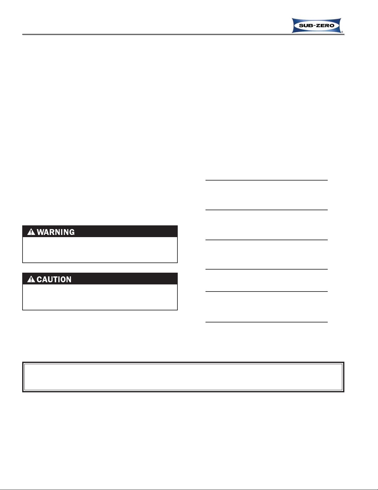
IMPORTANT SAFETY INFORMATION
Below are Product Safety Labels used in this manual.
The "Signal Words" used are WARNING or CAUTION.
When reviewing this manual, please note these different Product Safety Labels placed at the beginning of
certain sections of this manual. You must follow the
instructions given in the boxes of the Product Safety
Labels in order to avoid personal injury and/or product
damage.
The sample Product Safety Labels below illustrate the
precautions that should be taken when the signal word
is observed.
INTRODUCTION
This Technical Service Manual has been compiled to provide the most recent service information for Built-In Series
appliances. The information in this manual will enable the service technician to diagnose malfunctions, perform necessary repairs, and return a Built-in Series unit to proper operational condition.
The service technician should read the complete instructions contained in this manual before initiating any repairs.
INDICATES THAT HAZARDOUS OR UNSAFE
PRACTICES COULD RESULT IN SEVERE PERSONAL INJURY OR DEATH!
Indicates that hazardous or unsafe practices could
result in minor personal injury, and/or product
damage, and/or property damage!
In addition, please pay attention to the signal word
“NOTE”, which highlights information that is especially
important for the topic being covered.
This manual is designed to be used by Authorized Service Personnel only. Sub-Zero, Inc. assumes no
responsibility for any repairs made on Sub-Zero refrigeration units by anyone other than Authorized
Service Technicians.
The information and images contained in this manual are the copyright property of Sub-Zero, Inc. Neither this man-
ual nor any information or images contained herein may be copied or used in whole or in part without the express
written consent of Sub-Zero, Inc.©, all rights reserved.
Page 5

Section 1 - General Information 1-1
Introduction / Safety Information / Technical Assistance .. 1-2
Table of Contents .............................................................. 1-3
Warranty Information ........................................................ 1-5
Model Description ............................................................. 1-6
Section 2 - Inst
allation Information 2-1
Installation Considerations ............................................... 2-2
Tools and Materials Required ........................................ 2-2
Site Preparation ............................................................. 2-2
Finished Rough Opening Spec’s
30” & 36” Over / Under .......................................... 2-3
36” All Refrigerator All Freezer ............................... 2-4
36”, 42” & 48” Side-by-Side .................................... 2-5
Anti-Tip Bracket Installation ....................................... 2-6
Standard Installation ............................................... 2-6
Flush Inset Application ........................................... 2-7
Electrical Requirements ................................................. 2-8
Plumbing Requirements ................................................ 2-8
Water Line Connections ............................................... 2-9
Water Filter Bypass Plug ............................................... 2-9
Leveling the Unit .......................................................... 2-10
Door Adjustments ........................................................ 2-10
Height Adjustments .................................................. 2-10
Side to Side, In and Out Adjustments ...................... 2-11
90° Door Stop .............................................................. 2-11
Door and Drawer Panels ............................................. 2-12
Door Handle / Handle-Side Trim Removal ............... 2-12
Drawer Handle / Handle-Side Trim Removal ........... 2-13
Glasswell - Dispenser Assembly .................................. 2-14
Control Panel Removal ............................................ 2-14
Bezel Removal ......................................................... 2-14
Anchoring the Unit ...................................................... 2-15
Section 3 - Electronic Control System Information
3-1
Terminology & Component Descriptions .......................... 3-2
Electronic Control System Overview ................................. 3-3
Control Board Layout & Summary Table ......................... 3-4
Control Panel Layout (UIM) .............................................. 3-5
Basic Electronic Control Input Operations ....................... 3-6
Unit ON/OFF ................................................................ 3-6
Adjusting Set-Point (Temp. Adjustment) ...................... 3-7
Icemaker System ON/OFF ........................................... 3-7
Maximize Ice Production Feature .................................. 3-8
Door Ajar Alarm Feature ON/OFF ................................ 3-8
Air Purification Feature ON/OFF ................................... 3-9
Accent Lighting System ON/OFF .................................. 3-9
Unique Electronic Control Input Operations ................... 3-10
Temperature Units Selection Mode ............................ 3-10
Contrast Adjust Mode (Adjusting LCD Contrast) .......... 3-11
Tone Adjust Mode (Adjusting Audible Chime Tone) ..... 3-12
Showroom Mode ........................................................ 3-13
Sabbath Mode ............................................................ 3-14
Manual Zone Disable Mode ....................................... 3-15
Manual Freezer Evaporator Defrost ........................... 3-16
Door Dispenser Control Input Operations ....................... 3-17
Changing Dispenser Lighting State ............................. 3-17
Dispensing Water ......................................................... 3-17
Dispensing Ice ............................................................. 3-17
Locking the Dispenser ................................................. 3-18
Delayed Dispense Reset Mode ................................... 3-18
Functions of Electronic Control System .......................... 3-19
Supply Power to Lighting System ................................ 3-19
Control Condenser Fan Operation ............................. 3-20
Monitor, Regulate & Display Ref Temperatures ........... 3-21
Additional Regulating of Ref Temperatures:
Variable Speed Evaporator Fans .......................... 3-22
Drawer Fans ..........................................................3-23
Monitor & Control Ref Fan-Assist Off-Cycle Defrost ... 3-24
Minimize Condensation on Refrigerator Door Glass ... 3-25
Monitor, Regulate & Display Fre Temperatures ........... 3-26
Additional Regulating of Fre Temperatures:
Variable Speed Evaporator Fan ........................... 3-27
Monitor & Control “Adaptive Defrost” of Freezer ......... 3-28
Monitor Water Flow Meter, Regulate Fill & Display
when New Water Filter is Needed ............................... 3-29
Monitor IM System / Display If Service is Needed ....... 3-30
Monitor Compressors / Displays If Service is Needed .3-31
Possible Instruction and Error Indicators ......................... 3-32
Service Input Operations ................................................. 3-34
Diagnostic Mode .......................................................... 3-34
Thermistor Location Code Table .............................. 3-35
Fault Code Recall Mode .............................................. 3-36
Fault Code Table with LCD Correlation .................... 3-37
Temperature Log Recall Mode ..................................... 3-39
Compartment Thermistors Only .............................. 3-39
All Thermistors ......................................................... 3-40
Temperature Log Event Indicators ........................... 3-41
Model Configuration Mode ........................................... 3-42
Model Code Table .................................................... 3-43
Manual Component Activation ..................................... 3-44
Component Activation Tables ................................... 3-45
Self Test Mode ............................................................. 3-46
Section 4 - Sealed System Information
4-1
HFC 134a Refrigerant Information ................................... 4-2
General 134a Rules ...................................................... 4-2
Sealed System Repair Procedures Table ......................... 4-3
Sealed System Operation ................................................. 4-4
Refrigerant Flow Diagrams ............................................... 4-6
Section 5 -
Air Flow 5-1
Models BI-30U, BI-30UG, BI-36U, BI-36UG ...................... 5-2
Model BI-36F...................................................................... 5-2
Models BI-36R, BI-36RG .................................................. 5-3
Models BI-36S, BI-342S, BI-48S ...................................... 5-3
Models BI-342SD, BI-48SD .............................................. 5-4
TABLE OF CONTENTS
Page #
Page #
1-3
Built-In (BI) Series
Built-In (BI) Series
General Information
#7005333 - Revision A - January, 2008
Page 6

1-4
General Information
Built-In (BI) Series
Built-In (BI) Series
#7005333 - Revision A - January, 2008
Page #
Section 6 - Icemaker Information 6-1
Icemaker System Information............................................ 6-2
Icemaker Components....................................................... 6-2
Icemaker Operation............................................................ 6-3
Manually Stopping Icemaker.............................................. 6-8
Manually Starting Icemaker................................................ 6-9
Icemaker Fault Testing..................................................... 6-10
Quick Reference .......................................................... 6-10
Troubleshooting ........................................................... 6-10
Section 7 - Component
Access and Removal
7-1
Section 7 Table of Contents .............................................. 7-2
Section 8 - T
roubleshooting Guides 8-1
Troubleshooting Guides .................................................... 8-2
Using the Fault Code Troubleshooting Guide .............. 8-2
Fault Code Table with LCD Correlation ..................... 8-3
Fault Code Troubleshooting Guide ........................... 8-5
Using the General Troubleshooting Guide ................. 8-11
General Troubleshooting Guide .............................. 8-12
Sealed System Diagnostic Tables ............................. 8-14
Normal Operating Pressures Table ....................... 8-14
Pressure Indications Table .................................... 8-15
Temperature / Pressure Table ............................... 8-15
Section 9 - T
echnical Data Tables 9-1
Model BI-30U .................................................................... 9-2
Model BI-30UG ................................................................. 9-3
Model BI-36F .................................................................... 9-4
Model BI-36R .................................................................... 9-5
Model BI-36RG ................................................................. 9-6
Model BI-36S .................................................................... 9-7
Model BI-36U .................................................................... 9-8
Model BI-36UG .................................................................. 9-9
Model BI-42S ................................................................... 9-10
Model BI-42SD ................................................................ 9-11
Model BI-48S ................................................................... 9-12
Model BI-42SD ................................................................ 9-13
Page #
Section 10 - Wiring Diagrams & Schematics 10-1
Models BI-30U, BI-36U .................................................... 10-2
High Voltage Diagram .................................................. 10-2
Low Voltage Diagram ................................................... 10-3
Control Board Detail, Summary Table ..........................10-4
Wire Schematics .......................................................... 10-5
Model BI-36F ................................................................... 10-6
High Voltage Diagram .................................................. 10-6
Low Voltage Diagram ................................................... 10-7
Control Board Detail, Summary Table ..........................10-8
Wire Schematics .......................................................... 10-9
Model BI-36R ................................................................ 10-10
High Voltage Diagram ................................................ 10-10
Low Voltage Diagram ................................................. 10-11
Control Board Detail, Summary Table ....................... 10-12
Wire Schematics ........................................................ 10-13
Models BI-36S, BI-42S, BI-48S ..................................... 10-14
High Voltage Diagram ............................................... 10-14
Low Voltage Diagram ................................................. 10-15
Control Board Detail, Summary Table ....................... 10-16
Wire Schematics ........................................................ 10-17
Models BI-42SD, BI-48SD ............................................ 10-18
High Voltage Diagram ............................................... 10-18
Low Voltage Diagram ................................................. 10-19
Control Board Detail, Summary Table ....................... 10-20
Wire Schematics ........................................................ 10-21
Page 7

1-5
Built-In (BI) Series
Built-In (BI) Series
General Information
#7005333 - Revision A - January, 2008
WARRANTY INFORMATION
This page summarizes the 2, 5 & 12 Year Warranty pro-
vided with every Sub-Zero appliance, as well as the two
special warranties:
• Non-Residential Warranty - Applies to units
installed in non-residential applications.
• Display/Model Home Warranty - Applies to distrib-
utor and dealer display units, and units in model
homes, sold three years after date of manufacture.
Following the warranty summaries are details and notes
about the warranties.
TWO, FIVE & TWELVE YEAR Warranty
• 2 year TOTAL PRODUCT, *parts and labor.
NOTE: Stainless Steel doors, panels, grilles & product frames are covered by a 60 day parts & labor
warranty for cosmetic defects.
• 5 Year SEALED SYSTEM, **parts and labor.
• 6th - 12th year LIMITED SEALED SYSTEM, **parts
only.
ONE & FIVE YEAR Non-Residential Warranty
(Example: Office, Yacht, etc.)
• 1 Year TOTAL PRODUCT, *parts and labor.
NOTE: Stainless Steel doors, panels, grilles & product frames are covered by a 60 day parts & labor
warranty for cosmetic defects.
• 5 Year SEALED SYSTEM, **parts and labor.
ONE & FIVE YEAR Display/Model Home Warranty
(Display units sold three years after date of manufacture)
• 1 Year TOTAL PRODUCT, *parts and labor.
NOTE: Stainless Steel doors, panels, grilles & product frames are covered by a 60 day parts & labor
warranty for cosmetic defects.
• 5 Year SEALED SYSTEM, **parts and labor.
Figure 1-1. Serial Tag Layout (Layout Reference Only)
Warranty Details:
* Includes, but is not limited to the following:
Electronic Control System Components, Fan & Light
Switches, Fan Motors & Blades, Defrost Heaters,
Defrost Terminator, Drain Pan, Drain Tubes, Wiring,
Light sockets & bulbs, Icemaker, Water Valve, Door
hinges, Door closers & Cams, Compressor
Electricals, etc. . .
NOTE: Stainless Steel doors, panels, grilles & product frames are covered by a 60 day parts & labor
warranty for cosmetic defects.
** Includes the following:
Compressors, Condenser, Evaporators, Filter-Driers,
Heat-exchangers, All Tubing that Carries the Freon.
NOTE: Condenser Fan Motors, Freon, Solder and
compressor electricals are NOT
considered sealed
system parts.
Warranty Notes:
• All warranties begin at unit's initial installation date.
• All Warranty and Service information collected by
Sub-Zero is arranged and stored under the unit serial
number, and the customer's last name.
Sub-Zero requests that you have the model and serial
numbers available whenever contacting the factory or
parts distributor.
• The serial tag on ALL-REFRIGERATOR and ALLFREEZER models is located by the top door hinge in
the refrigeration compartment.
• The serial tag on SIDE-BY-SIDE models is located by
the top door hinge in the freezer compartment.
• The serial tag on OVER / UNDER models is located
by the top door hinge in the refrigerator compartment.
R
ALSO VERIFIED IN
ACCORDANCE WITH
ENERGY STANDARD
CAN/CSA - C300-91
Date Code
776N
LISTED
CUS
LISTED HOUSEHOLD
REFRIGERATOR OR FREEZER
L
U
R134a
REFRIGERANT
SERIAL NUMBER
MADISON, WI
PRODUCT SERVICE 1-800-222-7820
MODEL
115Vac, 60Hz, 1 Phase
TOTAL AMPS
FREEZER CO., INC.
8.3
FREEZER
6.5 oz
REFRIGERATOR
5.5 oz
BI-36U F3000000
Model Number
Serial Number
Manufacture Date
Refrigerant Charge
Total Amps Refrigerant Type
Page 8

MODEL DESCRIPTIONS
The diagram below (See Figure 1-2) explains the full model number code of the Built-in Series. The tables starting
on the following page list the basic model numbers, which are all the digits up to the letter after the first forward
slash, and are accompanied by diagrams of the basic models.
NOTE: Functional parts are common to each model configuration, meaning for example, models BI-36UG/S/PH-RH,
BI-36UG/S/PH-LH, BI-36UG/S/TH-RH , BI-36UG/S/TH-LH, etc., will utilize common functional parts. For this reason, only the basic model numbers are used in this manual , unless otherwise specified.
1-6
General Information
Built-In (BI) Series
Built-In (BI) Series
#7005333 - Revision A - January, 2008
BI-36UG/S/PH-RH
Model Line and
Domestic/International Identifier:
BI = Domestic Built-in Model Line
ICBBI = CB Approved International
Built-in Model Line
Nominal Cabinet Width:
Currently 30”, 36”, 42” and 48”
Stainless Steel Handle Style:
NOTE: Only present if trim style
is Stainless Steel.
/TH = Tubular Handle
/PH = Pro Style Handle
/CH = Curved Handle
Model Type:
S = Side-by-Side
U = Over / Under
R = All Refrigerator
F = All Freezer
Additional Model Type Information:
NOTE: If needed.
G = Glass Refrigerator Door
A = High Altitude Glass Refrigerator Door
D = Ice & Water Dispenser
Trim Style:
/F = Framed
/O = Overlay
/S = Stainless Steel
Door Swing:
NOTE: Only present if model
is door swing sensitive.
-RH = Hinge on Right Side
-LH = Hinge on Left Side
Figure 1-2. Model Number Code
Page 9

1-7
Built-In (BI) Series
Built-In (BI) Series
General Information
#7005333 - Revision A - January, 2008
Model BI-36R
BI-36R/F
BI-36R/O
BI-36R/S
MODEL DESCRIPTION
Built-In Series, 36” Wide, All-Refrigerator, Framed
Door Trim with Handle, Louver Grille (Standard)
Built-In Series, 36” Wide, All-Refrigerator, Overlay
Door Trim (No Handle), Panel Grille (Standard)
Built-In Series, 36” Wide, All-Refrigerator, Classic
Stainless Steel Wrapped Door, Stainless Steel
Grille (Standard)
Model BI-36RG
BI-36RG/F
BI-36RA/F
BI-36RG/O
BI-36RA/O
BI-36RG/S
BI-36RA/S
MODEL DESCRIPTION
Built-In Series, 36” Wide, All-Refrigerator, Glass
Door, Framed Door Trim with Handle, Louver
Grille (Standard)
(Same as above with High Altitude Glass)
Built-In Series, 36” Wide, All-Refrigerator, Glass
Door, Overlay Door Trim (No Handle), Panel
Grille (Standard)
(Same as above with High Altitude Glass)
Built-In Series, 36” Wide, All-Refrigerator, Glass
Door, Classic Stainless Steel Wrapped Door,
Stainless Steel Grille (Standard)
(Same as above with High Altitude Glass)
Page 10

1-8
General Information
Built-In (BI) Series
Built-In (BI) Series
#7005333 - Revision A - January, 2008
Model BI-30UG
BI-30UG/F
BI-30UA/F
BI-30UG/O
BI-30UA/O
BI-30UG/S
BI-30UA/S
MODEL DESCRIPTION
Built-In Series, 30” Wide, Over/Under, Glass
Refrigerator Door, Framed Door Trim with
Handles, Louver Grille (Standard)
(Same as above with High Altitude Glass)
Built-In Series, 30” Wide, Over/Under, Glass
Refrigerator Door, Overlay Door Trim (No
Handles), Panel Grille (Standard)
(Same as above with High Altitude Glass)
Built-In Series, 30” Wide, Over/Under, Glass
Refrigerator Door, Classic Stainless Steel
Wrapped Doors, Stainless Steel Grille (Standard)
(Same as above with High Altitude Glass)
Model BI-30U
BI-30U/F
BI-30U/O
BI-30U/S
MODEL DESCRIPTION
Built-In Series, 30” Wide, Over/Under, Framed
Door Trim with Handles, Louver Grille (Standard)
Built-In Series, 30” Wide, Over/Under, Overlay
Door Trim (No Handles), Panel Grille (Standard)
Built-In Series, 30” Wide, Over/Under, Classic
Stainless Steel Wrapped Doors, Stainless Steel
Grille (Standard)
Model BI-36F
BI-36F/F
BI-36F/O
BI-36F/S
MODEL DESCRIPTION
Built-In Series, 36” Wide, All-Freezer, Framed
Door Trim with Handle, Louver Grille (Standard)
Built-In Series, 36” Wide, All-Freezer, Overlay
Door Trim (No Handle), Panel Grille (Standard)
Built-In Series, 36” Wide, All-Freezer, Classic
Stainless Steel Wrapped Door, Stainless Steel
Grille (Standard)
Page 11

1-9
Built-In (BI) Series
Built-In (BI) Series
General Information
#7005333 - Revision A - January, 2008
Model BI-36U
BI-36U/F
BI-36U/O
BI-36U/S
MODEL DESCRIPTION
Built-In Series, 36” Wide, Over/Under, Framed
Door Trim with Handles, Louver Grille (Standard)
Built-In Series, 36” Wide, Over/Under, Overlay
Door Trim (No Handles), Panel Grille (Standard)
Built-In Series, 36” Wide, Over/Under, Classic
Stainless Steel Wrapped Doors, Stainless Steel
Grille (Standard)
Model BI-36UG
BI-36UG/F
BI-36UA/F
BI-36UG/O
BI-36UA/O
BI-36UG/S
BI-36UA/S
MODEL DESCRIPTION
Built-In Series, 36” Wide, Over/Under, Glass
Refrigerator Door, Framed Door Trim with
Handles, Louver Grille (Standard)
(Same as above with High Altitude Glass)
Built-In Series, 36” Wide, Over/Under, Glass
Refrigerator Door, Overlay Door Trim (No
Handles), Panel Grille (Standard)
(Same as above with High Altitude Glass)
Built-In Series, 36” Wide, Over/Under, Glass
Refrigerator Door, Classic Stainless Steel
Wrapped Doors, Stainless Steel Grille (Standard)
(Same as above with High Altitude Glass)
Page 12

1-10
General Information
Built-In (BI) Series
Built-In (BI) Series
#7005333 - Revision A - January, 2008
Model BI-42S
BI-42S/F
BI-42S/O
BI-42S/S
MODEL DESCRIPTION
Built-In Series, 42” Wide, Side-by-Side, Framed
Door Trim with Handles, Louver Grille (Standard)
Built-In Series, 42” Wide, Side-by-Side, Overlay
Door Trim (No Handles), Panel Grille (Standard)
Built-In Series, 42” Wide, Side-by-Side, Classic
Stainless Steel Wrapped Doors, Stainless Steel
Grille (Standard)
Model BI-42SD
BI-42SD/F
BI-42SD/O
BI-42SD/S
MODEL DESCRIPTION
Built-In Series, 42” Wide, Side-by-Side, Ice/Water
Dispenser, Framed Door Trim with Handles,
Louver Grille (Standard)
Built-In Series, 42” Wide, Side-by-Side, Ice/Water
Dispenser, Overlay Door Trim (No Handles),
Louver Grille (Standard)
Built-In Series, 42” Wide, Side-by-Side, Ice/Water
Dispenser, Classic Stainless Steel Wrapped
Doors, Louver Grille (Standard)
Model BI-36S
BI-36S/F
BI-36S/O
BI-36S/S
MODEL DESCRIPTION
Built-In Series, 36” Wide, Side-by-Side, Framed
Door Trim with Handles, Louver Grille (Standard)
Built-In Series, 36” Wide, Side-by-Side, Overlay
Door Trim (No Handles), Panel Grille (Standard)
Built-In Series, 36” Wide, Side-by-Side, Classic
Stainless Steel Wrapped Doors, Stainless Steel
Grille (Standard)
Page 13

1-11
Built-In (BI) Series
Built-In (BI) Series
General Information
#7005333 - Revision A - January, 2008
Model BI-48SD
BI-48SD/F
BI-48SD/O
BI-48SD/S
MODEL DESCRIPTION
Built-In Series, 48” Wide, Side-by-Side, Ice/Water
Dispenser, Framed Door Trim with Handles,
Louver Grille (Standard)
Built-In Series, 48” Wide, Side-by-Side, Ice/Water
Dispenser, Overlay Door Trim (No Handles),
Louver Grille (Standard)
Built-In Series, 48” Wide, Side-by-Side, Ice/Water
Dispenser, Classic Stainless Steel Wrapped
Doors, Louver Grille (Standard)
Model BI-48S
BI-48S/F
BI-48S/O
BI-48S/S
MODEL DESCRIPTION
Built-In Series, 48” Wide, Side-by-Side, Framed
Door Trim with Handles, Louver Grille (Standard)
Built-In Series, 48” Wide, Side-by-Side, Overlay
Door Trim (No Handles), Panel Grille (Standard)
Built-In Series, 48” Wide, Side-by-Side, Classic
Stainless Steel Wrapped Doors, Stainless Steel
Grille (Standard)
Page 14

1-12
General Information
Built-In (BI) Series
Built-In (BI) Series
#7005333 - Revision A - January, 2008
Page 15

Installation Information
2-1
#7005333 - Revision A - January, 2008
Built-In (BI) Series
Built-In (BI) Series
SECTION 2
INSTALLATION
INFORMATION
 Loading...