

Page 1

subzero.com 800.222.7820
BBQ
Service Manual
General Information 2
Controls & Operation 6
Installation Information 13
Component Access & Removal 18
Troubleshooting Guide 39
Technical Data 43
Page 2
OOUUTTDDOOOORR BBBBQQ GGRRIILLLLSS
General Information
1-2
TECHNICAL ASSISTANCE
If you should have any questions regarding a Wolf
appliance and/or this manual, please contact:
Wolf Appliance, Inc.
ATTN: Service Department
P.O. Box 44988
Madison, WI 53744-4988
Customer Service
Phone #: (800) 222-7820
Technical Assistance
Phone #: (800) 919 - 8324
Parts / Warranty Claims
Phone #: (800) 332 - 9513
Customer Service E-Mail Address
customerservice@wolfappliance.com
Customer Service & Technical Assistance
Facsimile #: (608) 441 - 5887
Parts / Warranty Claims
Facsimile #: (608) 441 - 5886
Office Hours:
7:00 AM to 7:00 PM Central Standard Time
Monday through Friday
This manual is designed to be used by Authorized Service Personnel only. Wolf Appliance, Inc. assumes
no responsibility for any repairs made to Wolf appliances by anyone other than Authorized Service
Technicians.
IMPORTANT SAFETY INFORMATION
Below are the Product Safety Labels used in this manual. The "Signal Words" used are WARNING and
CAUTION.
Please note that these safety labels are placed in areas
where awareness of personal safety and product safety
should be taken and lists the precautions to be taken
when the signal word is observed.
INTRODUCTION
This Wolf Outdoor BBQ Grills Technical Service/Parts Manual, Part #803332, has been compiled to provide the most
recent technical service information about the Wolf Appliance, Inc. BBQ Grills. This information will enable the service technician to troubleshoot and diagnose malfunctions, perform necessary repairs, and return a Wolf Outdoor
BBQ Grill to proper operational condition.
The service technician should read the complete instructions contained in this Training/Service Manual before initiating any repairs on a Wolf Appliance.
* Some information in section 2 (Theory of Operation) has been provided by the American Gas Association
and reprinted with their approval.
INDICATES THAT HAZARDOUS OR UNSAFE PRACTICES COULD RESULT IN SEVERE PERSONAL
INJURY OR DEATH
Indicates that hazardous or unsafe practices could
result in minor personal injury or product and/or
property damage
In addition, please pay attention to the signal word
“NOTE”, which highlights especially important information within each section.
The information and images are the copyright property of Wolf Appliance, Inc., an affiliate of Sub-Zero, Inc. Neither
this manual nor any information or images contained herein may be copied or used in whole or in part without the
express written permission of Wolf Appliance, Inc., an affiliate of Sub-Zero, Inc. © Wolf Appliance, Inc., all rights
reserved.
Page 3
General Information
1-5
OOUUTTDDOOOORR BBBBQQ GGRRIILLLLSS
WARRANTY INFORMATION
This page contains a summary of the 2 & 5 Year
Warranty that is supplied with every Wolf product, fol-
lowed by details and notes about the warranties.
TWO & FIVE YEAR Warranty Summary
• Two year TOTAL PRODUCT warranty, parts and
labor.
• Limited Parts Only Warranty for the 3rd through 5th
year on the following parts only:
Gas Burners (excluding appearance)
LIMITED LIFETIME WARRANTY SUMMARY
• Repair or Replace any BBQ body which rust
through due to defective material or workmanship.
• Repair or replace any BBQ hood which rust
through due to defective material or workmanship.
• Labor to remove or replace defective parts is not
covered.
Warranty Details:
The warranty applies only to products installed for
normal residential use. The warranty applies only
to products installed in the United States or
Canada.
Warranty Notes:
• All warranties begin at the time of the units initial
installation.
• All Warranty and Service information collected by
Wolf Appliance, Inc. is arranged and
stored under the unit serial number and/or the customer’s name. Please note that Wolf Appliance,
Inc. requests that you have the model
and serial number available whenever contacting
the factory or parts distributor.
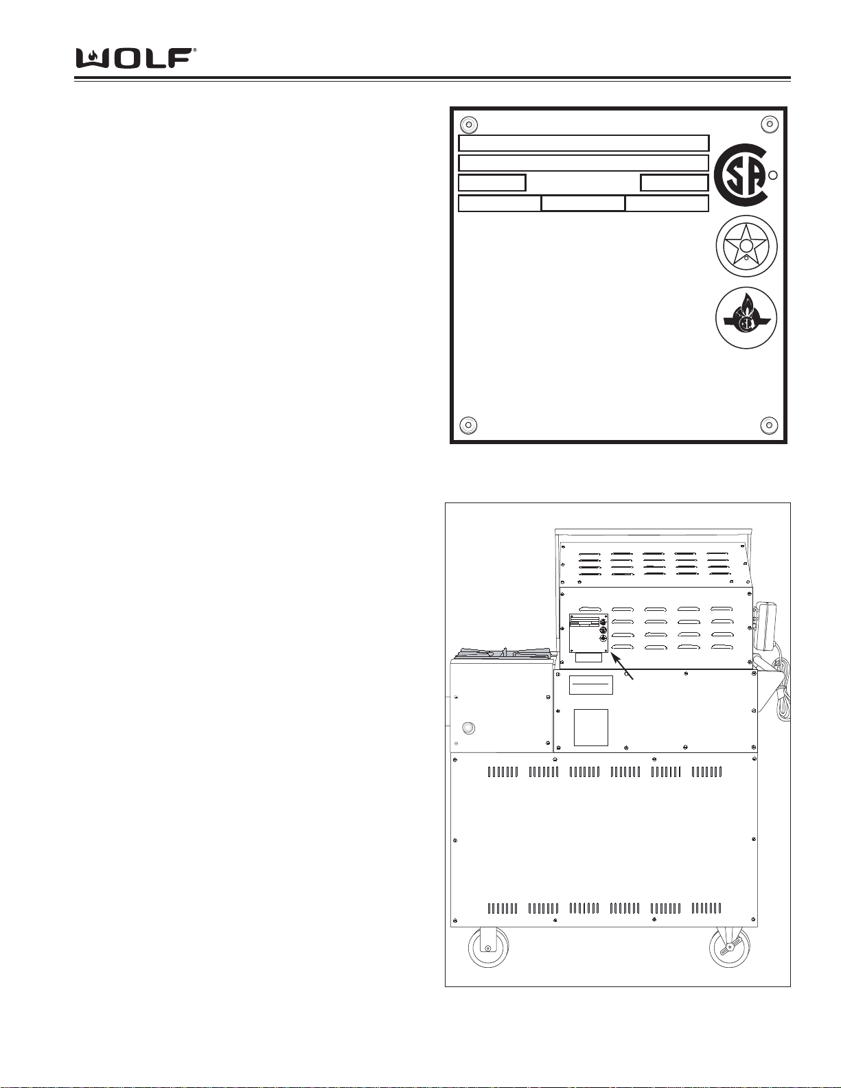
• See Figure 1-1 for serial plate layout.
• See Figure 1-2 for serial plate location.
CERTIFIED
D
E
S
I
G
N
A
M
E
R
I
C
A
N
A
S
S
O
C
I
A
T
I
O
N
R
G S
A
C
E
R
T
I
F
I
E
D
R
WOLF
APPLIANCE CO. LLC FITCHBURG, WI
MODEL
BBQ-
SERIAL
NO.
GAS
GRILL
ROTISSERIE
MAN.
PRESS.
OPEN
BURNER
INPUT RATING EACH
BURNER-BTU / HR.
ROTISSERIE MOTOR ELECTRICAL RATING
120V, 60 Hz, 0.58A
MINIMUM CLEARANCE FROM SIDES AND BACK OF UNIT TO ADJACENT
COMBUSTIBLE CONSTRUCTION BELOW TOP OF UNIT, 8 INCHES FROM
SIDES AND BACK. MINIMUM HORIZONTAL CLEARANCE FROM SIDES
AND BACK OF UNIT TO ADJACENT VERTICAL COMBUSTABLE
CONSTRUCTION EXTENDING ABOVE TOP OF UNIT, 6 INCHES FROM SIDES
ANS 12 INCHES FROM BACK. DO NOT LOCATE THIS UNIT UNDER
OVERHEAD UNPROTECTED COMBUSTIBLE SURFACES.
FOR OUTDOOR USE ONLY.
CAUTION:
1. DO NOT STORE A SPARE LP-GAS CYLINDER UNDER THIS
APPLIANCE.
2. NEVER FILL THE CYLINDER BEYOND 80 PERCENT FULL..
3. IF THE INFORMATION IN (1) AND (2) IS NOT FOLLOWED EXACTLY
A FIRE CAUSING DEATH OR SERIOUOS INJURY MAY OCCUR.
"ANSIZ21.58A CAN/CGA-1.6A-1998 OUTDOOR COOKING APPL.,"
"FOR INSTALLATION IN NON-COMBUSTIBLE LOCATIONS UNLESS
USED WITH APPROVED INSULATING JACKET"
800116
Figure 1-1 Typical Serial Plate Layout
FOR USE WITH A GAS PRESSURE REGULATOR. THE REGULATOR SUPPLIED
MUST BE USED WITH THIS UNIT.
CET APPARIEL REQUIERT L' INSTALLATION D' UN DETENDEUR DE PRESSION.
LE DETENDEUR FOURNI DOIT Y ENTRE
INSTALLE.
WARNING: Improper installation
adjustment, alteration, service, or
maintenance can cause property
damage, injury or death. Read the
maintenance instructions thoroughly
before installing or servicing this
equipment.
MISE EN GARDE: Une mauvaise
installation, un mauvais entretien,
une reparation, un ajustement ou
une alteration inappropiee peuvent
causer des dommages a lappariel,
des blessures corporels ou la mort.
Lire les instructions d'installation,
de fonctionnement et d'entretien
avant l'installation ou lentretien de
cet appareil.
For Wolf Authorized Service
CALL
888-904-9653
CERTIFIED
D
E
S
I
G
N
A
M
E
R
I
C
A
N
A
S
S
O
C
I
A
T
I
O
N
R
G S
A
C
E
R
T
I
F
I
E
D
R
WOLF
APPLIANCE CO. LLC FITCHBURG, WI
MODEL
BBQ-
SERIAL
NO.
GAS
GRILL
ROTISSERIE
MAN.
PRESS.
OPEN
BURNER
INPUT RATING EACH
BURNER-BTU / HR.
ROTISSERIE MOTOR ELECTRICAL RATING
120V, 60 Hz, 0.58A
MINIMUM CLEARANCE FROM SIDES AND BACK OF UNIT TO ADJACENT
COMBUSTIBLE CONSTRUCTION BELOW TOP OF UNIT, 8 INCHES FROM
SIDES AND BACK. MINIMUM HORIZONTAL CLEARANCE FROM SIDES
AND BACK OF UNIT TO ADJACENT VERTICAL COMBUSTABLE
CONSTRUCTION EXTENDING ABOVE TOP OF UNIT, 6 INCHES FROM SIDES
ANS 12 INCHES FROM BACK. DO NOT LOCATE THIS UNIT UNDER
OVERHEAD UNPROTECTED COMBUSTIBLE SURFACES.
FOR OUTDOOR USE ONLY.
CAUTION:
1. DO NOT STORE A SPARE LP-GAS CYLINDER UNDER THIS
APPLIANCE.
2. NEVER FILL THE CYLINDER BEYOND 80 PERCENT FULL..
3. IF THE INFORMATION IN (1) AND (2) IS NOT FOLLOWED EXACTLY
A FIRE CAUSING DEATH OR SERIOUOS INJURY MAY OCCUR.
"ANS Z21.58A CAN/CGA-1.6A-1998 OUTDOOR COOKING APPL.,"
"FOR INSTALLATION IN NON-COMBUSTIBLE LOCATIONS UNLESS
USED WITH APPROVED INSULATING JACKET"
800116
Figure 1-2 The serial plate is located on the backside of
the Rear Hood Top.
Serial Plate
Page 4

OUTDOOR BBBQ GGRILLS
General Information
1-6
MODEL FEATURES:
All Models:
Wolf BBQ grills are constructed with heavy duty 18-gauge stainless steel. The hood is a two piece stainless steel
design with a handle. All grates are made from porcelainized cast iron. A grill scraper and protective cover is provided with each unit.
Wolf BBQ grills are assembled to either work with natural gas or LP gas. Converting a unit from one gas type to
another is not possible. There are built-in models and freestanding cart models. Cart models are currently equipped
with 5” locking swivel casters at both ends, with older models having non-swivel wheels at one end. The grill burner
tubes are made of stainless steel and have a 10,000 BTU (British Thermal Unit) rating. Every Wolf BBQ grill is also
equipped with a rotisserie burner, rated at 9,000 BTU’s, with a 115 volt rotisserie motor for turning the rotisserie rod.
Side Burner Models:
Some models are equipped with two porcelain cast iron side step-up burners. These burners have a 16,000 BTU
rating.
LP Gas Models:
LP gas units include a regulator, hose and 5-gallon LP tank.
MODEL NUMBER DESCRIPTIONS
This section briefly describes the reason for different model numbers. The BBQ’s are manufactured as either natural
gas or LP gas, built-in or on a free standing cart.
• The two digits “24”, “36”, “48” following the letters BBQ indicate the width of the grill chassis in inches.
Example: BBQ24
2C = 24” chassis.
• An additional number such as “2”, after the first two digits indicates there are two side step-up burners.
Example: BBQ242
C = Two side step-up burners.
• The letter “C” which appears in some of the models is for cart.
Example: BBQ242C
= Cart model.
• When there is “BI” in the model number, it indicates that the unit will be built in.
Example: BBQ242BI
= Built in unit.
• The “-LP” at the end of the model number indicates the unit is manufactured to operate on LP gas.
Example: BBQ242C-LP = LP gas.
BBQ MODEL NUMBERS IN SUMMARY:
• BBQ = Grill
• 24, 36, 48 = Indicates the width in inches of the grill chassis.
• 2 = This number following the first two digits indicates two side step-up burners.
• C = Cart
• BI = Built in.
• -LP = Indicates LP gas. When -LP is not at the end of the model number it indicates the unit is manufactured
for Natural gas.
Page 5

General Information
OUTDOOR BBBQ GGRILLS
MODEL NUMBER KEY
Refer to this key for an example of the model numbers.
Model: BBQ362BI-LP
Product Type
Size
Side Burners
Features
Fuel
Product T
ype
BBQ
Size
24 24 - Grill Space
36 30 - Grill Space
48 36 - Grill Space
Side Burners
2
Features
Built In
Cart
Fuel
LP Propane Gas
* No -LP indicates the unit is manufactured for Natural gas.
Page 6
OUTDOOR BBBQ GGRILLS
General Information Notes
1-8
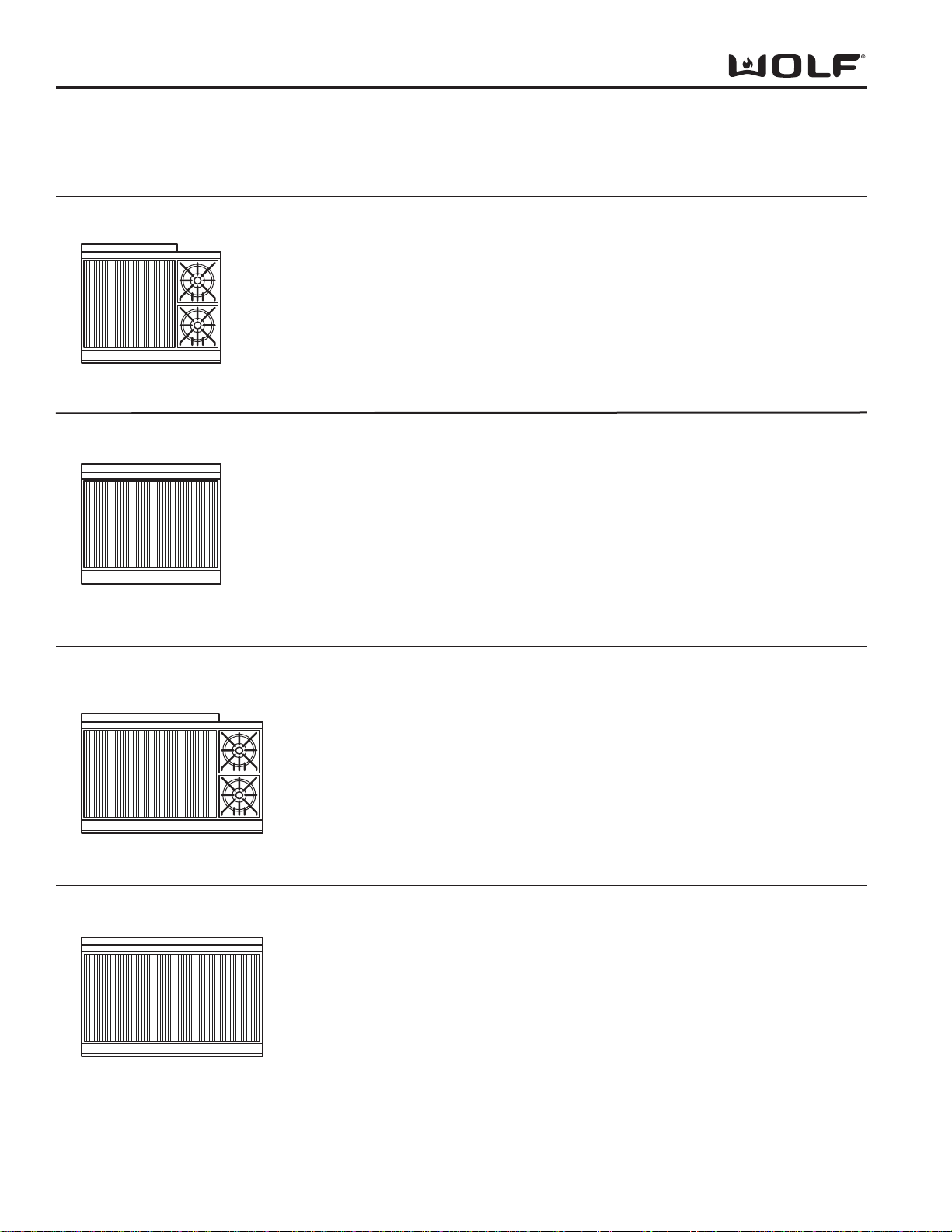
TOP CONFIGURATIONS FOR OUTDOOR BBQ GRILLS
Configuration
Model #
Description
BBQ242BI
BBQ242BI-LP
BBQ242C
BBQ242C-LP
24” Grill with Two Open Burners, Built-In (Nat. Gas)
24” Grill with Two Open Burners, Built-In (LP)
24” Grill with Two Open Burners on 36” Cart (Nat. Gas)
24” Grill with Two Open Burners on 36” Cart (LP)
All 24” Grills have Four Grill Burners
BBQ36BI
BBQ36BI-LP
BBQ36C
BBQ36C-LP
36” Grill, Built-In (Nat. Gas)
36” Grill, Built-In (LP)
36” Grill on 36” Cart (Nat. Gas)
36” Grill on 36” Cart (LP)
All 36” Grills have Six Grill Burners
BBQ362BI
BBQ362BI-LP
BBQ362C
BBQ362C-LP
BBQ48BI
BBQ48BI-LP
BBQ48C
BBQ48C-LP
36” Grill with Two Open Burners, Built-In (Nat. Gas)
36” Grill with Two Open Burners, Built-In (LP)
36” Grill with Two Open Burners on 48” Cart (Nat. Gas)
36” Grill with Two Open Burners on 48” Cart (LP)
All 36” Grills have Six Grill Burners
48” Grill, Built-In (Nat. Gas)
48” Grill, Built-In (LP)
48” Grill on 48” Cart (Nat. Gas)
48” Grill on 48” Cart (LP)
All 48” Grills have Eight Grill Burners
Page 7

OUTDOOR BBBQ GGRILLS
Theory of Operation
2-2
THEORY OF OPERATION
A service technician should understand how a gas appliance operates before attempting to service the appliance.
This section provides descriptions of the different types of fuel gases and explains gas heating values. A definition
of specific gravity of gas is given along with its characteristics and effects. Gas combustion principles are explained
and gas burner components are described and illustrated. The end of this section contains illustrations which
demonstrate basic cooking appliance theory of operation.
Types of Fuel Gas:
Gases used to supply heat energy are called fuel gases. Common fuel gases are not simply one kind of hydrocarbon, they are mixtures of hydrocarbon gases. They contain other gases as well, such as free hydrogen, carbon
dioxide and nitrogen. As an example, natural gas might contain 85% methane, 12% ethane and 3% of other gases.
The presence of each of these gases in the fuel gas has some effect on the nature of the gas.
Some common fuel gasses are methane [CH
4], ethane [C2H6], Propane [C3H8] and butane [C4H10]. Propane and
butane are nearly odorless. Natural gas that is processed to remove condensables and moisture, has little or no
odor and no color. Odorants are added to natural gas before distribution to aid in leak detection. A common odorant
used is a colorless liquid containing sulfur compounds.
Heating Value of Gas:
Heat energy produced when burning a fuel gas is commonly expressed in British Thermal Units (BTU). One BTU of
heat will raise the temperature of one pound of water one degree Fahrenheit.
The more carbon and hydrogen atoms in each molecule of a fuel gas, the higher its heating value. Natural gas
which is high in methane has a heating value of about 950 to 1150 BTU per cubic foot. The variance is due to the
various other substances found in natural gases. The more ethane, propane or butane in the gas raises the heating
value. Propane, or LP gas, has a heating value of about 2500-2800 BTU per cubic foot, and butane about 3200
BTU per cubic foot.
Specific Gravity of Gas:
The specific gravity of a gas is the weight of one cubic foot, or the gas compared to one cubic foot of dry air. When
stating the specific gravity of a gas, a pressure and temperature must be clearly stated. In the gas industry, the
standard conditions of pressure and temperature are 30.0 inches of mercury and 60° F. A pressure of 30.0 inches of
mercury will sustain a column of mercury 30 inches high in a tube with a vacuum on top of the column. Since air is
used as the reference, its specific gravity is always 1.0. This value of 1.0 has no direct physical meaning with
regard to air, such as its density. It is only a relative number or ratio used to express specific gravity of other gases.
The specific gravity of a gas will determine if the gas will rise or fall when released into the air. Natural gas will rise
since its specific gravity is less than 1.0 at 0.4 to 0.8. Propane has a specific gravity of 1.5 and butane 2.0. These
gases will fall when released into the air. They sometimes collect in low spots into pools which become a hazard if
open flames are present.
In addition, specific gravity has two other characteristics. It has an important effect on the flow of gases through orifices, and hence the rating of the burners. Gas flow through an orifice is dependent upon the orifice size and the
gas pressure upstream of the orifice. More of a lighter gas will flow through a given orifice size than a heavier gas
at the same gas pressure. This effect is taken into account in tables and calculators used to select orifice sizes for
burners.
Specific gravity also affects gas flow in pipes. A given driving pressure at a pipe inlet will move more lighter gas
than heavier gas through that pipe.
Page 8

Theory of Operation
2-3
OUTDOOR BBBQ GGRILLS
Principles of Gas Combustion:
Combustion - When oxygen acts with a substance to produce large amounts of heat rapidly.
Requirements for Combustion - There are three required elements for combustion to occur; Fuel (Gas), Oxygen
(Air) and Heat (Ignition Temperature, which for gas is between 1100°F/593°C and 1200°F/649°C). All must be present. Removing any one of the three and combustion will cease.
Chemistry of Combustion - Combustion of gas is a chemical reaction between fuel gas and oxygen. The basic
elements of common fuel gasses are hydrogen [H] and carbon [C]. When hydrogen burns, water vapor [H
2O] is pro-
duced. Complete burning of carbon in fuel gases form carbon dioxide [CO2] and water vapor [H2
O].
Controlled Combustion - Controlled combustion takes place when gas and air are supplied at proper rates to
assure complete combustion of the gas in a steady flame. When a gas appliance is operating properly, burning
starts at the burner ports. Gas flow is controlled by gas orifice size and gas pressure upstream of the orifice. Air is
mixed with the gas before it passes through the burner ports. This added air is called “Primary Air”. The remaining
air required for complete combustion is supplied to the burner at the point of combustion and is called “Secondary
Air”.
Adjustments of the gas-to-air ratio and the secondary air supply is the key to obtaining stable blue flames at a burner. Proper amounts of primary and secondary air are required for quiet and efficient burner operation and for complete combustion of the gas. Air Shutters or other devices provide control of primary air. Inlet opening and flue outlets control Secondary Air flow.
Total air - In an ideal situation, primary and secondary air is all that is needed (for the oxygen required) to burn the
gas, but some additional air is required to assure complete burning of the gas. The total air, “primary”, “secondary”
and “excess” are expressed as percentages of the amount needed. About ten cubic feet of air is required to completely burn one cubic foot of gas. For this reason an appliance should not be operated in an air tight home.
Limits of Flammability - Not all air-to-gas mixtures will burn. Mixtures with 0% - 4% natural gas in air are too lean
to burn. Mixtures of 4% - 14% natural gas in air can burn with a controlled flame. Flammability limits come into play
when primary air adjustments are made on burners. If too much primary air is used, the mixture may become too
lean and fall below flammability limits, thus preventing combustion.
Incomplete Combustion (Causes and Effects) - To obtain complete combustion, sufficient amounts of air must be
supplied to the process. This air must have a reasonably normal oxygen content. Complete burning of gas produces harmless carbon dioxide gas and water vapor. If the air supply is insufficient, incomplete combustion occurs
resulting in the formation of toxic by-products, such as carbon monoxide [CO] or aldehydes.
Carbon monoxide is colorless and odorless. Inhaling carbon monoxide in sufficient quantities could cause death by
reducing oxygen levels in the blood.
Aldehydes, which are equally dangerous, have a sharp and penetrating odor which is easily detected by smell at
very low concentrations. The odor caused by aldehydes should not be confused with odorants added to natural gas.
The absence of aldehydes does not assure that carbon monoxide is not present. However, if the odor of aldehydes
is present, then carbon monoxide is virtually always present.
Gas Burner Operation - A gas burner is a device to burn gas under control in order to produce useful heat.
Primary air is brought into the burner from outside of the appliance at atmospheric pressure. The gas jet streaming
from the orifice draws primary air with it into the burner.
The gas/air mixture, combined with a spark at the burner port(s) and the secondary air creates a controlled burn.
Page 9

OUTDOOR BBBQ GGRILLS
Theory of Operation
2-4
Burner Components:
Gas Orifice - An opening or hole which regulates or limits the amount of gas flowing to a burner. Gas flow rate (vol-
ume) depends on the size of the orifice (hole) and the gas pressure at the inlet of the orifice.
Air Shutter - This is used to adjust the size of the primary air inlet area and therefore controls primary air flow.
Venturi Tube - A section of pipe at the inlet of the burner body that narrows and then flares out again. This tube
helps maintain a proper and constant primary air injection.
Mixing Tube/Throat - Serves to carry the gas/air mixture from the venturi tube to the burner body.
Burner Body - The accumulation chamber below the burner base which allows the gas and air to mix together fully.
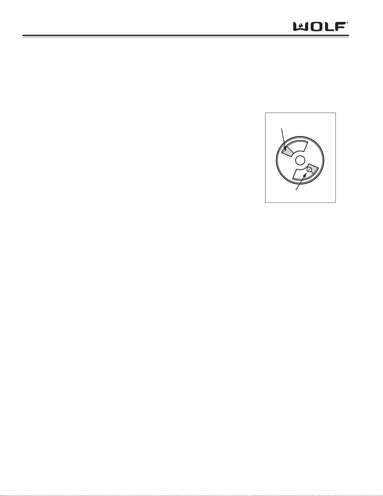
Burner Head - The component containing the burner ports where the gas/air mixture ignites. The burner ports are
distributed in a useful pattern to optimize heat transfer. The flames should be spread so they can be easily reached
by secondary air and provide a stable blue flame.
Air Shutter
Air Shutter
Burner Head
Mixing Tube/Throat
Burner Body
Venturi Tube
Venturi Tube
The Gas Orifice or hole
regulates or limits the amount
of gas flowing to a burner.
The part which contains the orifice
should be referred to as an orifice
Spud, Hood or Cap.
Fig. 2-1
Fig. 2-2
Fig. 2-3
Page 10
Theory of Operation
2-5
OUTDOOR BBBQ GGRILLS
Types of Burners:
Blue Flame Burners - All Wolf BBQ burners are blue flame burners. With this type of burner, primary air is mixed
with the fuel gas before the gas reaches the burner ports. An orifice is used to regulate gas flow to the burner. Air
which is mixed with the gas inside of the burner body enters through openings in the burner body. A shutter or venturi tube is used to adjust the size of these openings and control the primary air. Gas and air mix in the mixing tube
or throat, which then exits the burner ports where it is ignited. Secondary air is air from around the flames. The
flame produced has several zones, each represents a stage in burning of the gas. The burner tip has a thin dark
blue cone called the inner or primary cone. A lighter cone called the outer cone, surrounds the inner cone. Air
around the flame diffuses into the flame to burn at the outer cone. If conditions are perfect, products from the inner
cone burn here. The final products of burning are carbon dioxide and water vapor. An outer mantle surrounds the
outer cone where burning is usually completed. It is nearly invisible and glows only because of the high temperature
of the final combustion.
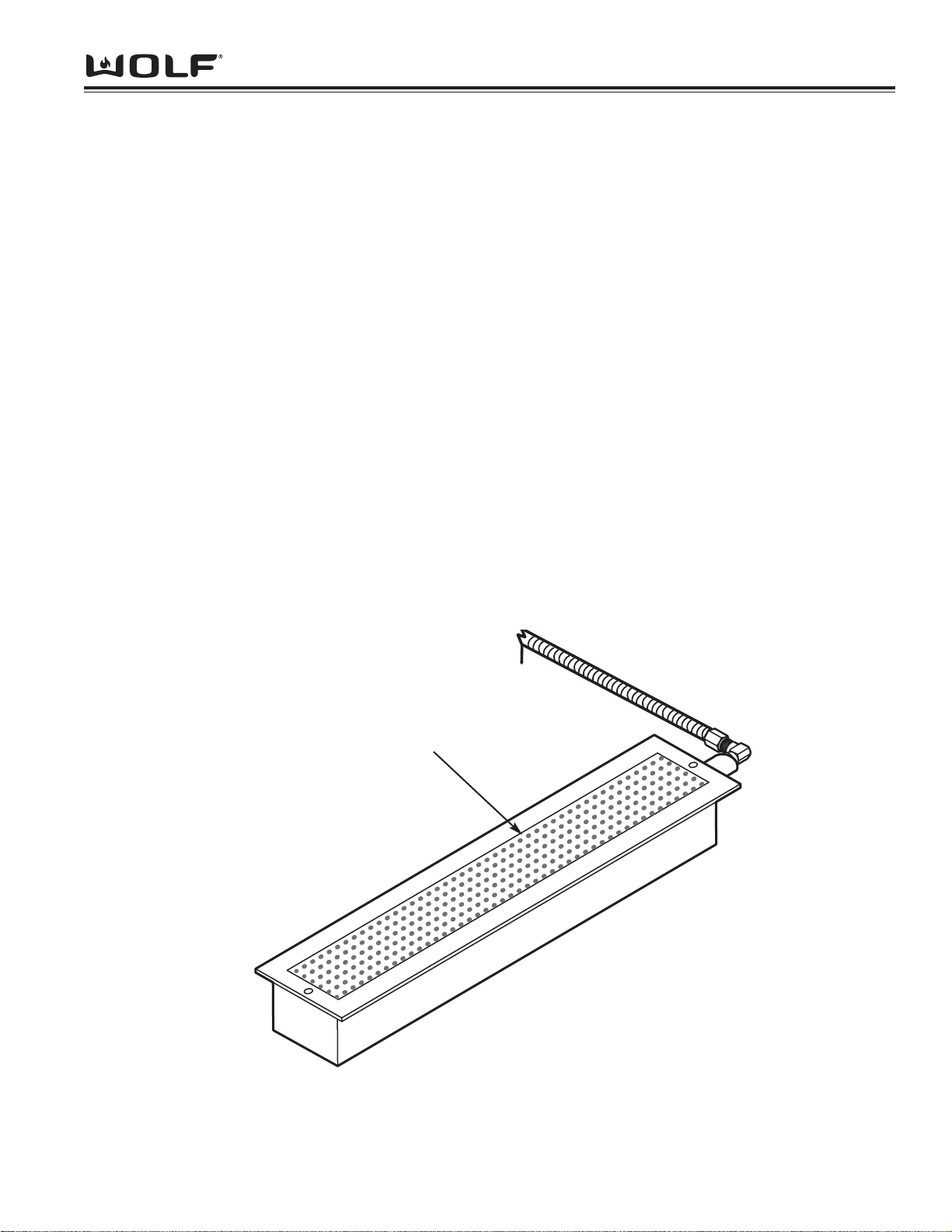
Infrared Burner - All Wolf gas BBQ’s use an infrared burner for the rotisserie. This infrared burner is a porous
refractory ceramic tile burner, similar to the infrared burner used in the ranges and cooktops. (See Figure 2-4) With
infrared heat, thermal energy is transmitted through space without heating the medium through which it travels.
Infrared energy is usually not affected by air flowing between the burners and heated surfaces because of the burner’s numerous and tiny flames. This type of heat is very efficient and compact. The refractory ceramic infrared
burner requires 100 percent primary air and is designed to have a hot glowing burner surface. The flame burns
close to the burner surface at a high temperature.
NOTE: There is not a shutter on infrared burners for adjusting the primary air.
Fig.2-4
Porous Ceramic Surface
Page 11
OUTDOOR BBBQ GGRILLS
Theory of Operation
2-6
Operation of the Wolf BBQ Grill
About the Wolf BBQ
The grill grates are composed of five-inch heavy duty porcelain cast iron and are designed for easy handling and
cleaning. Just below the grill surface are the stainless steel heat radiants which concentrate the heat. The Wolf
BBQ design eliminates the use of briquettes or lava rock. BBQ burners produce 10,000 BTU/hr and are located
every five inches across the bottom of the unit. The optional open top side burners are rated at 16,00BTU/hr and
have a spark igniter for rotary knob lighting.
Lighting Instructions
The Wolf BBQ Grill is pre-set for the gas specified when the unit is purchased,
either natural or LP gas. The properly adjusted flame should have a bluish-green
inner cone and a dark blue outer mantle. The flame should be clean and soft
with no yellow tips. Blowing or lifting of the flame should not occur. If the air
shutters are not visible as in Fig. 2-5, the shutter adjustment is
made by loosening the air shutter screw, setting then retightening.
(This should give you proper mixture of the air and gas.)
Before Lighting
Prior to lighting, inspect the gas supply piping or hose. Look for evidence of
abrasion, cuts, wear and tear, or other damage which would require replacement
prior to use. Make sure all burner control knobs are in the OFF position. Do not
attempt to light the burners if the smell of gas is present. Make sure there is
gas in the cylinder and the cylinder is upright. Make sure all radiants are positioned
properly over the grill burners.
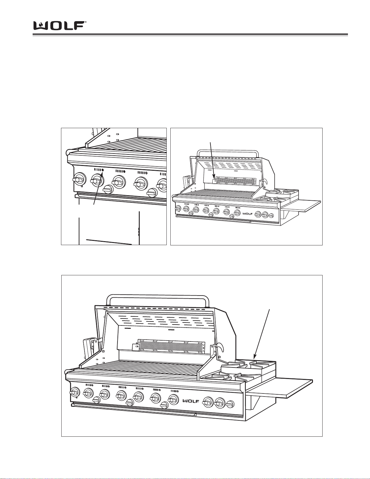
Lighting the Grill
1. Open the hood.
2. Push in the gas control knob for the grill and turn counter clockwise to HIGH.
3. Keep your face as far away from the burners as possible.
4. Turn the black igniter knob clockwise which corresponds with the gas control knob you have turned on until you
hear a loud click. Repeat immediately if the burner does not light on the first try.
5. Listen for a “whoosh” sound. If the burner does not light by the fourth attempt with the igniter, turn the control
knob to the OFF position. Wait five minutes until the gas clears.
6. Repeat the procedure or refer to the Manual Lighting Procedure.
7. If the burner is lit, you can see flames by looking through a series of holes just above the control knob of
the corresponding burner.
8. Upon successful lighting, repeat the process on the other burners as needed
Lighting the Open Burners
1. Remove the open burner cover or any utensils from the grate.
2. Follow the steps as above in lighting the grill.
NOTE: The front and rear open burners are lit by a single electrode. The igniter knob is the same for the front and
rear open burners.
Lighting the Rotisserie Burner
The position of the infrared rotisserie burner makes it more susceptible to be blown out and should not be used if
windy conditions prevail or in an unprotected area. For this reason the burner is equipped with a safety valve which
will not allow the burner to operate unless the pilot is lit.
1. Open the hood and remove the rotisserie burner cover.
2. Push in and turn the rotisserie gas control knob to HIGH.
3. After 15 to 30 seconds, turn the rotary igniter knob clockwise until a clicking sound is heard. (This will give the
gas enough time to travel through the tubing to the pilot at the left corner of the burner.)
4. Once the pilot is lit, the burner will light in approximately 30 seconds. The flame is not visible but will give off
heat and a red-orange glow after a few minutes.
Fig. 2-5
1/16” for Natural
1/4” for LP
Air Shutter Screw
Page 12
Theory of Operation
2-7
OUTDOOR BBBQ GGRILLS
Manual Lighting Procedure
You may manually light the grill burners by inserting the match/lanyard holder or a butane lighter into the 1/2” diameter hole above the grill valve knob (Fig. 2-6). Position the match or the lighter tip near the burner ports, push and
turn the knob counter clockwise to HIGH and light the burner. Repeat for the other burners.
The open burners can be lit directly from the top along the orifice holes around the burner heads. (Fig. 2-8)
The rotisserie burner must be lit at the pilot. Once the pilot is lit, the burner will light within 30 seconds. (Fig. 2-7)
Fig. 2-7Fig. 2-6
Position the Match/Lanyard with a lit
match over the Open Burner Head.
Push and turn Burner Valve Knob
counter clockwise to HIGH and light
burner.
Fig. 2-8
Use Match/Lanyard to
light Rotisserie at Pilot
Insert Match/Lanyard
to manually light Grill
Page 13
OUTDOOR BBBQ GGRILLS
Theory of Operation
2-8
Cleaning and Maintenance
Burner Grates
The grates are composed of durable cast iron with a
porcelain enamel finish. Operating the grill on High for
a few minutes after cooking will help to burn off any
excess food. The wire brush included with the BBQ
can be used to clean the grill grates. Once the grates
have cooled, they can be lifted off and sprayed with a
commercial grill and stainless cleaner. They must be
rinsed and dried before they are put back into place.
Open Burner Grates
These grates are porcelain cast iron and can be wiped
clean while in place. They can also be removed when
cool and cleaned with warm soapy water.
Open Burner Heads
Simply lift the removable porcelain cast iron burner
heads straight up. Clean clogged gas holes with an
open paper clip or wire. Wash with soapy water, dry
and replace.
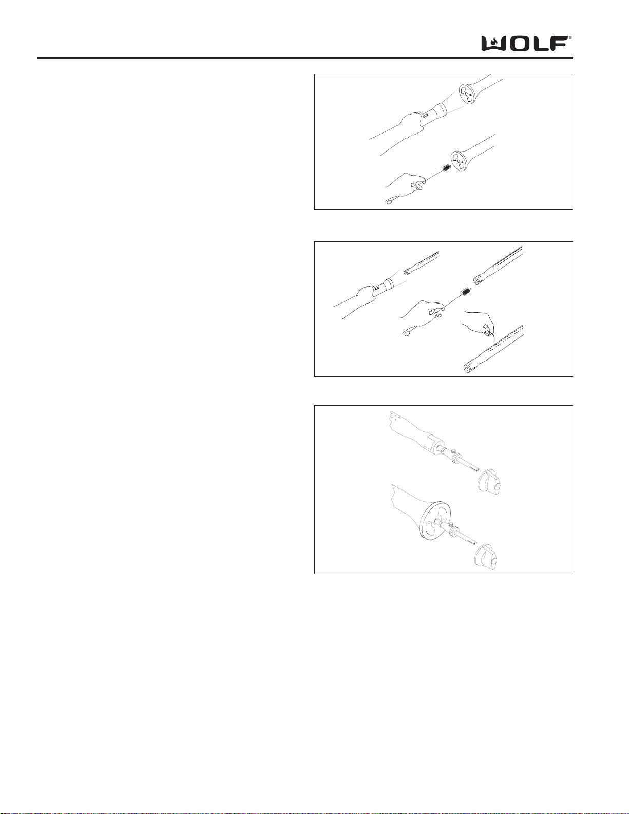
Venturis
Spiders or small insects may spin webs or build nests
inside of the venturis. This especially occurs in late
summer and fall when spiders are most active. These
nests can obstruct gas flow and cause a fire in and
around the valve. Such a fire can cause operator injury
and serious damage to the grill.
To help prevent a blockage and ensure full heat output,
follow these steps to clean and inspect the venturis
once or twice a month.
1. Using a flashlight, look inside of the end of the burners for webs or mud nests. See Fig. 2-9
2. Use the special venturi brush provided and push the
brush through the full length of each burner several
times. See Fig. 2-9
3. For the grill venturis, clean the gas holes with a
paper clip if blocked. See Fig. 2-10
4. Replace the venturis and make sure the bell shaped
or cylindrical end is located over the valve orifices.
See Fig. 2-11
5. Test light to see if it is burning properly.
Grill Tank Bottom
If there is an accumulation of carbon or burned food on the bottom of the grill, use a spatula or scraper to push all
of the carbon and food to the front and into the drip pan to collect and dispose.
Drip Trays and Grease Cans
After cooling, the drip trays and grease cans may be removed and cleaned. The grease can should be cleaned after
each use.
Fig. 2-9
Fig. 2-10
Fig. 2-11
Page 14
OUTDOOR BBBQ GGRILLS
Installation Information
3-2
Insulated Jacket
The optional insulated jacket is necessary when the non cart grill is to be installed into a combustible enclosure.
Use only the Wolf approved insulated jacket which has been specifically designed and tested for this purpose.
See Fig. 3-2
Clearance to Combustible Construction
A minimum of 12” from the sides and 12” from the back is required above and below the cooking surface to adjacent
vertical combustible surfaces as shown on page 3-3. A minimum of 4-1/2” from the back is required for the hood to
open and 6” to the side is required for the rotisserie motor. Refer to the illustrations and chart on page 3-3.
INSTALLATION INFORMATION
This section of the manual covers some of the installation issues that a service technician may need to know when
servicing a Wolf BBQ. If additional installation information is needed after reviewing this section of the manual,
please refer to the Installation Guide or contact the Wolf Appliance Customer Service Department.
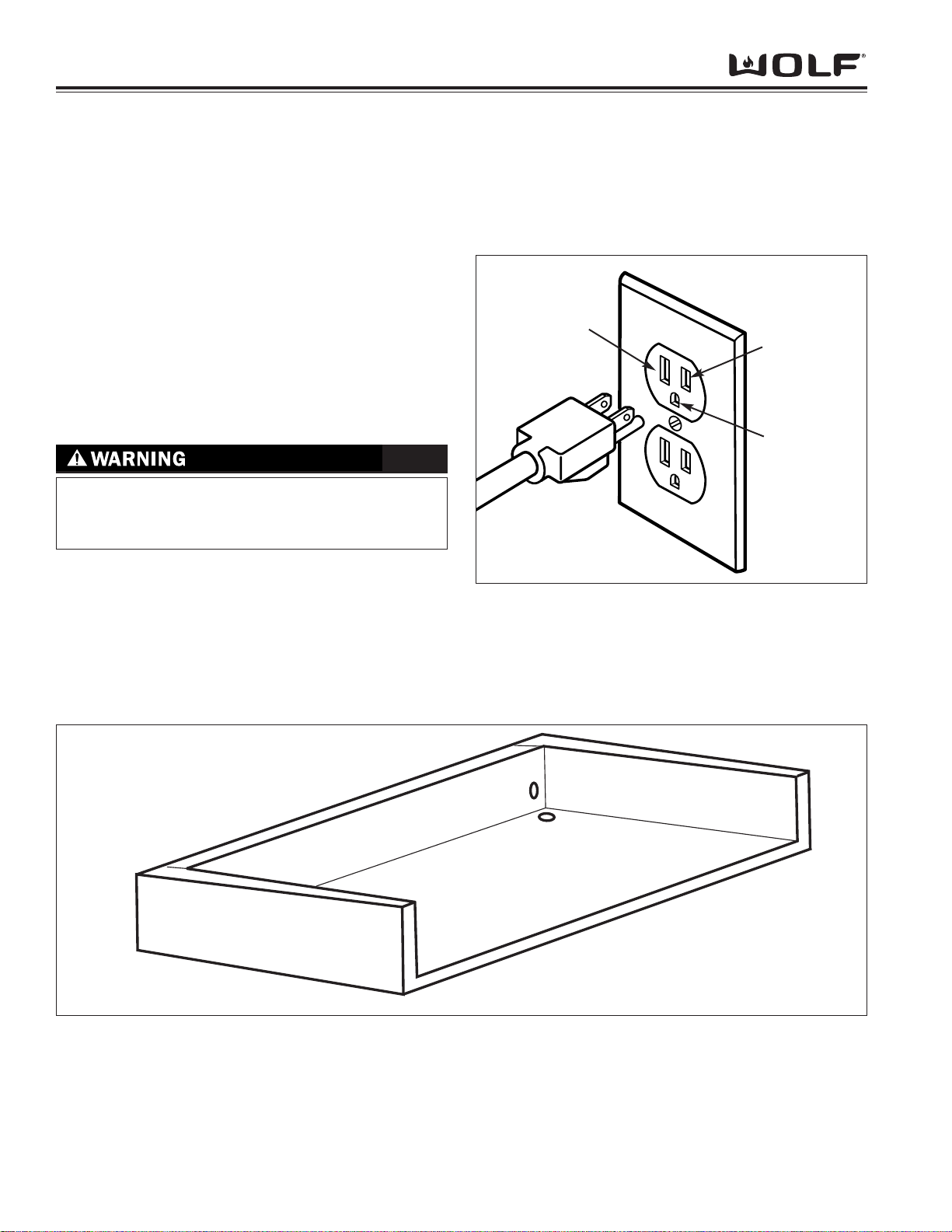
Electrical Requirements:
A Wolf BBQ rotisserie motor requires 110-120 volts AC to
operate. The power supply cord on the rotisserie motor is
equipped with a 3-prong (grounding) plug. The installation
site must be equipped with a properly grounded 3-prong
receptacle. If the electric receptacle or the power cord are
not properly grounded and polarized, a shock hazard could
exist and the rotisserie motor may experience problems.
(See Figure 3-1)
Neutral
Line
Voltage
(Power)
Ground
Fig. 3-1. Proper Polarity at Electric Receptacle
TO AVOID SHOCK HAZARD, NEVER REMOVE THE
GROUNDING PRONG FROM THE PLUG OF THE
POWER SUPPLY CORD.
Note: Keep electrical supply cords and the fuel supply
hose away from heated surfaces.
Fig. 3-2 Insulated Jacket
Page 15

Installation Information
3-3
OUTDOOR BBBQ GGRILLS
Pre-Installation Specifications
Overall / Pre-Installation Dimensions Model BBQ242 Model BBQ36 Model BBQ362 Model BBQ48
A Overall Width of Grill 36” 36” 48” 48”
B Width of Hood 24” 36” 36” 48”
C Rough Opening Width (Combustible Enclosure) 38 1/4” 38 1/4” 50 1/4” 50 1/4”
D Rough Opening Width (Non-Combustible Enclosure) 36 1/4” 36 1/4” 48 1/4” 48 1/4”
Pre-Installation Dimensions Combustible Enclosure Non-Combustible Enclosure
E Rough Opening Depth 27 3/4” 26 3/4”
F Rough Opening Height 10 1/2” 9 1/2”
G Minimum Clearance to Side Walls 12” 6”
H Minimum Clearance to Back Wall 12” 4 1/2”
I Gas Supply Location (Back Wall/Bottom Location) 3 1/8” 2 1/8”
J Gas Supply Location (Back Wall Location) 3 3/4” 2 3/4”
K Gas Supply Location (Bottom Location) 2 7/8” 1 7/8”
Page 16

OUTDOOR BBBQ GGRILLS
3-4
Installation Information
Gas Requirements
Gas Pressure:
NOTE: All Wolf BBQ’s are manufactured as either natural gas or LP gas.
Natural Gas Manifold Pressure
Standard natural gas orifices on the BBQ are set for 5” WC (Water Column Pressure). A natural gas regulator is
provided.
Liquid Propane (LP) Manifold Pressure
Standard LP gas orifices on the BBQ are set for 10” WC (Water Column Pressure). An LP gas regulator is provided.
Gas Supply Pressure
• Maximum line pressure for natural gas and LP is 14” WC; 1/2 psi (3.5 kPa).
• Minimum line pressure for natural gas is 7” WC.
• Minimum line pressure for LP gas is 11” WC.
Gas Pressure Regulator
To control and maintain a uniform gas pressure in the gas manifold, Wolf gas appliances must be connected to the
gas supply line through a pressure regulator. The burner orifices are sized for the pressure delivered by the regulator. Never attempt to operate a Wolf gas appliance without the use of the proper pressure regulator.
The maximum gas supply pressure to the regulator is 14” WC (Water Column Pressure); 1/2 psi (3.5kPa) and
should not be exceeded.
Natural Gas Hook-Up
Hook-up to a natural gas supply is made from the rear right side with fittings and a regulator. The coupling, pipe,
nipple, street elbow and regulator are provided. To hook up the fittings refer to Fig. 3-3. Make sure the flow arrow
on the regulator points in the direction of the gas flow from the gas supply to the grill. See Fig. 3-4
Fig. 3-3 Fig. 3-4
3/4" Coupling
To Grill
3/4" x 3" Pipe Nipple
3/4" x 3/4" Street Elbow
Regulator
Manifold Pipe
3/4" x 1/2" Adapter*
1/2" Close Nipple*
Vent
Shut Off Valve*
(must be easily accessible)
* Indicates parts not included
From Gas Supply
Page 17

Installation Information
3-5
OUTDOOR BBBQ GGRILLS
LP Gas Hook Up
An LP Wolf BBQ is equipped with a five foot hose, regulator and unfilled 20 pound gas cylinder. This connection is
done with the cylinder located inside of the cart. See Fig. 3-5 and Fig. 3-6
Cylinder Specifications
The LP gas supply cylinder used with this grill must be approximately 12” in diameter and 18” high. The maximum
fuel capacity is 20 lbs. of propane or 5 gallons. Full cylinder weight should be approximately 38 lbs. (43.7 lbs. nominal water capacity). The LP gas supply cylinder must be provided with a listed over-filling prevention device. (DPD)
Approximate running time for a 20 pound LP tank:
BBQ Model #
BTU Rating Running Time
BBQ36 / BBQ36C 69,000 BTU 6-1/2 hours
BBQ242 / BBQ242C 80,000 BTU 5-1/2 hours
BBQ48 / BBQ48C 89,000 BTU 5 hours
BBQ362 / BBQ362C 101,000 BTU 4-1/2 hours
Fig. 3-5
VENT HOLE ON REGULATOR MUST POINT DOWN TO
PREVENT FREEZE UP DURING OPERATION OF GRILL
Vent Hole
NOTE: When connecting the regulator
with hose, you must coil excess hose
around LP Cylinder. Failure to do so could
result in pulsating flames or partial flame.
Fig. 3-6
VENT
To LP
Cylinder
To Grill
VENT
Vent
Manifold Pipe
Coupling Nut
VENT
Regulator with 5' Hose
LP Gas Cylinder
(Use in upright position only)
Page 18

OUTDOOR BBBQ GGRILLS
Installation Information
3-6
Installation Checklist
- All internal packaging has been removed.
- All shipping restraints have been removed from the burners.
- Specified clearances to any combustible materials have been maintained.
- All burners light properly, individually and simultaneously.
- All flames appear normal
- The drip pan slides freely. The grease can is properly placed.
- The pressure regulator is connected.
- The LP cylinder is in an upright position and the hose is not kinked.
- The unit has been tested and is free of leaks.
- The customer has been informed of the gas supply shut off valve locations.
- Radiants are located properly over the grill burners.
Leak Testing
A leak test should be performed every time the gas cylinder is connected to the regulator, and whenever part of the
gas system is disconnected or replaced. This applies to both natural and LP gas.
Test for leaks at the cylinder valve, cylinder welds, regulator (especially attached to cylinder valves), hose and connections.
NOTE: DO NOT use a flame, such as a lighted match to test for leaks. Use only a leak testing solution of soapy
water or an electronic leak detector.
Leak Testing Procedure
1. Check that all control knobs are in the OFF position.
2. Mix a one-part soap/one-part water solution. (If not using an electronic detector.)
3. Turn the cylinder valve knob counter-clockwise one turn to open.
4. Apply the soap/water solution on the joints of the gas delivery system.
5. The appearance of blowing bubbles in the soap solution indicates that a leak is present.
6. Stop the leak by tightening the loose connection or replacing the faulty part.
DO NOT attempt to repair the cylinder valve if it should become damaged. The cylinder must be replaced.
NOTE: It is important that there are no leaking connections on the BBQ grill. Refer to the Leak Testing Procedure.
Page 19

OUTDOOR BBBQ GGRILLS
Component Removal
COMPONENT ACCESS AND REMOVAL
This section explains how to access and remove components from a Wolf Outdoor BBQ Grill. Depending on which
component you are going to access or remove in the following sections, you may have to remove some components
first. Refer to the appropriate section in this manual that explains how to access and remove those various components. When reassembling, just reverse the steps that were used to acces and remove the components.
NOTE: Before attempting to access or remove any components from a Wolf Appliance, take note of the following
warnings.
- TO AVOID SERIOUS BURNS AND/OR EXPLOSIONS, KEEP COMBUSTIBLES AWAY FROM THE APPLIANCE
WHENEVER A FLAME IS PRESENT. KEEP IN MIND THAT SURFACES AND COMPONENTS GET HOT
DURING THE USE OF THE APPLIANCE.
- TO AVOID ELECTRICAL SHOCK, POWER TO THE UNIT MUST BE DISCONNECTED WHENEVER ACCESS
ING AND/OR REMOVING COMPONENTS POWERED BY ELECTRICITY OR COMPONENTS NEAR OTHER
ELECTRICAL COMPONENTS.
- IF IT IS NECESSARY TO REMOVE A UNIT FROM ITS INSTALLATION, REMEMBER THAT THE UNIT COULD
TIP FORWARD WHEN PULLED FORWARD, RESULTING IN SERIOUS INJURY OR DEATH. PULLING A
UNIT FROM ITS INSTALLATION SHOULD ONLY BE DONE BY AN AUTHORIZED SERVICE TECHNICIAN OR
INSTALLER.
Page 20

Component Removal
OUTDOOR BBBQ GGRILLS
OPEN BURNER COMPONENTS:
Components include; Open Burner Cover, Open Top
Grates, Step Up Frame, Burner Head, Front & Rear
Venturi, Spark Ground Strap, Spark Electrode, Spark
Electrode Mounting Bracket and Pilot Tube Bracket,
Burner Support Bracket
Open Burner Cover
The stainless steel open burner cover protects the open
burners from the weather when the open burners are
not is use. To remove the open burner cover, lift the
cover off. See Fig. 4-1
Fig. 4-1
Fig. 4-2
Fig. 4-3
Open Top Grates
The open top grates are used to place pots and pans
on the open top burners for cooking. To remove the
open top grates, lift them off of the open top frame.
See Fig. 4-2
Step-Up Frame
The step-up frame is stainless steel and is used to elevate the rear open top burner. To remove the step-up
frame you will need to extract the screws at the back of
the frame which mount it to the BBQ chassis. Now, lift
off the step-up frame from the chassis. See Fig. 4-3
Fig. 4-4
Burner Head
The burner head is made of cast iron and consists of
numerous holes that the gas and flame come out of. To
remove the burner head, lift the burner head off of the
burner venturi. See Fig. 4-4
Page 21

OUTDOOR BBBQ GGRILLS
Component Removal
Rear Venturi
The burner head sits on top of the rear venturi. The
rear venturi sits on the burner support bracket and
slides over the burner valve orifice. To remove the rear
venturi you must remove the open top grate. Now lift
the venturi up off of the burner support bracket and
slide it off of the burner valve orifice. Lift the rear venturi out through the burner support bracket.
See Fig. 4-6
Spark Ground Strap
The spark ground strap is mounted over the spark electrode and is secured to the spark electrode mounting
bracket. To remove the spark electrode ground strap
you will first need to remove the open top grates. Now
extract the screw that mounts the ground strap to the
spark electrode mounting bracket and remove the
ground strap. See Fig. 4-7
Front Venturi
The burner head sits on top of the front venturi. The
front venturi sits on the burner support bracket and
slides over the burner valve orifice. To remove the front
venturi you must remove the open top grate. Now lift
the venturi up and off of the burner support bracket and
slide it off of the burner valve orifice. Now lift the front
venturi out through the burner support bracket.
See Fig. 4-5
Fig. 4-5
Fig. 4-6
Fig. 4-7
Fig. 4-8
Spark Electrode
The spark electrode emits the spark produced by the
rotary igniter to the open top burners. To remove the
spark electrode you will need to remove the open top
burner grates. Now unplug the spark electrode from the
rotary igniter by reaching down along the open top
burner valve and unplugging it from the rotary igniter.
Cut any wire ties that secure the electrode wire. Now
extract the screw from the ground strap and remove the
ground strap. Now remove the spark electrode by
pulling it through the hole in the burner support bracket.
See Fig. 4-8
Page 22

Component Removal
OUTDOOR BBBQ GGRILLS
Spark Electrode Mounting Bracket
The spark electrode mounting bracket is used to mount
the spark electrode to the pilot burner tube. To remove
the spark electrode mounting bracket you will need to
remove the open top burner grates, spark electrode
ground strap and spark electrode. Now extract the
screw for the spark electrode mounting bracket and
remove the spark electrode mounting bracket from the
pilot tube and the burner support bracket.
See Fig. 4-9
Pilot Tube and Bracket
The pilot tube bracket allows gas to flow from the front
and rear open top burners to the spark electrode, which
will produce the flame for the burners once a spark has
been produced from the rotary igniters. To remove the
pilot tube bracket you will need to remove the open top
burner grates and the spark electrode with mounting
bracket. Now extract the screw that mounts the pilot
tube to the support bracket and remove the pilot tube.
See Fig. 4-10
Burner Support Bracket
The burner support bracket is used to support the open
top burners. To remove the burner support bracket you
will need to remove the open top grates, the front and
rear venturi and the step-up frame. Now unplug the
spark electrode from the rotary igniter by reaching down
along the open top burner valve and unplugging it from
the rotary igniter. Cut any wire ties that secure the
electrode wire and extract the two screws at the front of
the burner support bracket and remove. Now lift the
bracket up while pulling the bracket forward to disengage the tab of the support bracket from slot in the
open top frame. See Fig. 4-11
Fig. 4-9
Fig. 4-10
Fig. 4-11
Page 23

OUTDOOR BBBQ GGRILLS
Component Removal
GRILL COMPONENTS:
Components include; Broiler Grates, Radiant, Stainless
Steel Burner, Spark Electrode Ground Strap, Spark
Electrode Mounting Bracket and Spark Electrode.
NOTE: To remove the following components, you must
first raise the front hood.
Stainless Steel Burner
The stainless steel burner tubes are located under the
broiler grates and the radiant. They are long stainless
steel tubes with various holes along the entire length of
the tube.
NOTE: The size of the BBQ unit will determine the
number of burner tubes.
The burner tube fits into a slot on the rear of the grill
chassis. The front of the burner tubes slides over the
orifice on the burner valve. To remove the stainless
steel burner tubes you need to first remove the broiler
grates and the radiant. Then lift the back of burner tube
out of the slot and slide the burner tube off of the burner
valve orifice and out. See Fig. 4-14
Radiant
The radiant is placed on pins that are welded to the grill
chassis, at both the front and back. When the radiant is
placed on top of the holding pins, it is raised just above
the burner tube. The flame from the burner tube is
directed onto the underside of the radiant, distributing
the heat to the sides, rather than directly onto the food
being prepared. To remove the radiant you need to
remove the broiler grates from the grill chassis and then
lift the radiant off of the radiant pin holders.
See Fig. 4-13
Fig. 4-12
Fig. 4-13
Broiler Grates
The grilling surface is composed of numerous broiler
grates. To remove the broiler grates, lift them from the
grill chassis. See Fig.4-12
Page 24

Component Removal
OUTDOOR BBBQ GGRILLS
Spark Electrode Mounting Bracket
The spark electrode mounting bracket holds the spark
electrode and ground strap. To remove the spark electrode mounting bracket you will need to remove the
broiler grates and radiant. Lower the control panel and
unplug the spark electrode from the rotary igniter and
cut any wire ties that secure the electrode wire. Pull
the electrode wire with sleeve through the hole in the
BBQ chassis. Then remove the ground strap and spark
electrode. Now extract the screws that secure the
mounting bracket to the BBQ chassis and remove the
spark electrode mounting bracket. See Fig. 4-16
Spark Electrode Ground Strap
The spark electrode ground strap secures the spark
electrode to the spark electrode mounting bracket. To
remove the spark electrode ground strap you will need
to remove the broiler grates and radiant. Now extract
the screw that secures the ground strap to the mounting bracket and remove ground strap. See Fig. 4-15
Spark Electrode
The spark electrode emits the spark supplied from the
rotary igniter to light the gas in the burner tube. To
remove the spark electrode you will need to remove the
front control panel. Once the control panel has been
removed, unplug the spark electrode wire from the
rotary igniter. Remove the broiler grates, radiant,
ground strap and spark electrode mounting bracket.
Now pull the spark electrode and sleeve through the
hole and out of the grill chassis. See Fig. 4-17
Fig. 4-15
Fig. 4-16
Fig. 4-17
Page 25

OUTDOOR BBBQ GGRILLS
Component Removal
FRONT CONTROL PANEL COMPONENTS:
Components include; Control Knob, Igniter Knob,
Control Panel, Rotary Igniter and Match Holder with
Lanyard.
Control Knob
To remove, pull the knob straight off of the burner valve
shaft. See Fig. 4-18
Igniter Knob
To remove, pull the knob straight off of the rotary igniter
shaft. See Fig. 4-18
Fig. 4-18
Fig. 4-20
Fig. 4-21Fig. 4-19
Match Holder with Lanyard
The match holder is used to secure a lighted match to
light the burner if the rotary igniter fails to produce a
spark. It is riveted to the bottom of the control panel.
To replace it, you will have to drill out the rivet.
See Fig. 4-21
Rotary Igniter
To remove the rotary igniter, first remove the rotary
igniter knobs and the control knobs. Remove the control panel and unplug the electrode wire from the rotary
igniter. Next extract the two screws that mount the
rotary igniter to the control panel. Then pull the rotary
igniter from the control panel. See Fig. 4-20
Control Panel
Begin by removing all of the control panel knobs.
Extract the screws from the bottom left and right corners of the panel. Pull the bottom of the panel out
about 30 degrees and lift slightly to disengage the top
flange of the panel from its mounting. Then lift the top
forward. See Fig. 4-19
Page 26

Component Removal
OUTDOOR BBBQ GGRILLS
COMPONENTS BELOW THE BULL NOSE:
Components include; Bull Nose, Burner Valve, Burner Valve Orifice Hood, Valve Adapter, Tee, Nipple, Connector,
Pilot Valve and the Manifold Pipe.
Bull Nose Removal
To remove the bull nose, extract the two screws from the left and right legs of the bull nose and lift the bull nose
from the unit. See Fig. 4-22
Fig. 4-22
Fig. 4-23
Burner Valve
The burner valves are threaded into the underside of
the manifold assembly. To remove a burner valve, you
will need to turn off the gas supply, remove the broiler
grates, radiant, stainless steel burner tube, control
knobs, control panel and unplug the spark electrode
wires from the rotary igniters. Now using a wrench,
loosen and remove the burner valve. See Fig. 4-23
Burner Valve Orifice Hood
The burner valve orifice is threaded onto the end of the
burner valve. To remove the burner valve orifice you
will need to turn off the gas supply, remove the broiler
grates, radiant, stainless steel burner tube, control
knobs, control panel and unplug the spark. Now using
a wrench, loosen and remove the burner valve orifices
hood. See Fig. 4-23
Page 27

OUTDOOR BBBQ GGRILLS
Component Removal
Valve Adapter and Tee
The valve adapter is threaded onto the end of the infrared rotisserie burner valve. It allows the tee adapter to be
threaded on, so the rotisserie burner valve can supply gas to the pilot valve and the safety valve for the infrared
burner. To remove the valve adapter you will need to turn off the gas supply, remove the control knobs, control
panel and unplug the spark electrode wires from the rotary igniter. Now, loosen and remove the pilot valve gas tubing from the pilot valve and loosen and remove the gas tubing from the safety valve to the connector on the tee
adapter. Then loosen and remove the entire valve adapter/tee assembly as one unit. Once the assembly has been
removed from the unit, remove the valve adapter from the tee. See Fig. 4-24
Nipple and Connector
The nipple is threaded on the end of the tee, which allows the connector for the flexible gas tubing to be threaded
on. This flexible gas tubing goes to the safety valve which supplies gas to the infrared burner. To remove the nipple
you will need to turn off the gas supply, remove the control knobs, control panel and unplug the spark electrode
wires from the rotary igniter. Now you will need to loosen and remove the pilot valve gas tubing from the pilot valve
and loosen and remove the gas tubing from the safety valve to the connector on the tee adapter. Now loosen and
remove the entire valve adapter/tee assembly as one unit. Once the assembly is removed from the unit, you can
remove the nipple from the connector and the tee. See Fig. 4-24
Pilot Valve
The pilot valve is threaded into the bottom of the tee. It allows for a separate gas supply to go to the pilot light for
the infrared burner. To remove the pilot valve you need to turn off the gas supply, remove the control knobs, control
panel and unplug the spark electrode wires from the rotary igniter. Now you will need to loosen and remove the pilot
valve gas tubing from the pilot valve and loosen and remove the flexible gas tubing from the safety valve to the connector on the tee adapter. Now loosen and remove the entire valve adapter/tee assembly as one unit. You can now
loosen and remove the pilot valve from the tee. See Fig. 4-24
Manifold Pipe
The manifold pipe is connected to the gas source at one end and is sealed at the other end. It supplies gas to the
burner valves, pilot valve and safety valve. To remove the manifold you need to turn off the gas supply, remove the
control knobs, control panel and unplug the spark electrode wires from the rotary igniter. Now you will need to
loosen and remove the pilot valve gas tubing from the pilot valve and loosen and remove the flexible gas tubing from
the safety valve to the connector on the tee adapter. Now disconnect the manifold from the gas source. Extract the
screws that secure the manifold to the grill chassis and remove the manifold by pulling straight out of the grill chassis. See Fig. 4-24
Fig. 4-24
Manifold Pipe
Tee
Connector
Nipple
Grill Burner Valve
Pilot Valve
Rotisserie Burner Valve
Valve Adapter
Page 28

Component Removal
OUTDOOR BBBQ GGRILLS
Fig. 4-26
Fig. 4-25
Fig. 4-27
HOOD COMPONENTS:
Components include; Rotisserie Rod with Fork,
Rotisserie Motor, Motor/Rod Support, Hood Handle,
Front Hood, Rear Hood Top, Rear Hood Left and Right,
IR Burner Cover with Handle, Pilot Shield, Infrared
Burner, Pilot Burner, Spark Electrode, Rear Splash
Panel, Side Plate Shelf, Side Plate Shelf Brackets and
Belly Bar with Brackets.
Rotisserie Rod with Fork
The rod for the rotisserie system is assembled into the
motor by placing the pointed end into the motor and
resting the threaded end on the support at the right side
of the grill. Once the rod is pushed as far as possible
into the motor, the grooved end of the rod should rest
on the right side bracket. The removable rotisserie
handle should be removed when using the open burners. To remove the rotisserie rod with fork, lift the rod
out of the support bracket on the right side. Now pull
the rod out of the rotisserie motor. See Fig. 4-25
Rotisserie Motor
The rotisserie motor is equipped with metal gears and
is capable of turning a balanced 25 lb. cut of meat or
poultry. The motor is mounted to a metal bracket,
which attaches to the sides of the grill and must be
electrically grounded. To remove the rotisserie motor
you first need to unplug the rotisserie motor from the
electrical source. Remove the rotisserie rod with fork,
now lift the rotisserie motor straight up and out of the
motor support bracket. See Fig. 4-26
Rotisserie Motor/Rod Support
The motor support holds the rotisserie motor in place
and is mounted to the left side hood. To remove the
motor support bracket you need to extract the acorn
nuts from screws. Then extract the mounting screws
from the bracket. Now lift the bracket off of the left side
of the hood.
The rod support bracket holds one end of the rotisserie
rod and is mounted on the right side hood. To remove
the rod support, extract the mounting screws and lift
bracket off right side hood. See Fig. 4-27
Page 29

OUTDOOR BBBQ GGRILLS
Component Removal
Fig. 4-28
Fig. 4-29
Fig. 4-30
Hood Handle
The hood handle is attached to the hood from the
inside. To remove the hood handle you need to remove
the plug buttons from the inner hood liner to gain
access to the mounting bolts for the handle. Now
extract the bolts from the handle and lift the handle from
the front hood. See Fig. 4-28
Front Hood
The hood is used to provide an even temperature, conserve fuel, lessen flare-up and improve food flavor. To
remove the hood you will first need to remove the rotary
motor rod support bracket. Now extract the shoulder
screw and nut from the flanged bushing on the left and
right side of the hood. Lift off the front hood.
See Fig. 4-29
Rear Hood Top
The rear hood top is connected to the right and left side
hood, and is slotted for ventilation. It covers the
infrared burner and gas tubing. In order to remove the
rear hood, the front hood will need to be removed. To
remove the rear hood, remove the screws along the
right and left side hood. Remove the screws along the
middle of the rear hood. The middle screws mount the
rear hood to the rear splash panel. Now lift off the rear
hood. See Fig. 4-30
Rear Hood Right and Left
The rear hood right and left makes-up the side of the
hood. In order to remove the rear hood right and left,
the front hood and rear top hood need to be removed.
Remove the screws that are located inside the grill
chassis for each side hood. Once that is done, lift out
the side hoods. See Fig. 4-31
Fig. 4-31
Page 30

Component Removal
OUTDOOR BBBQ GGRILLS
Fig. 4-32
Fig. 4-33
Infrared (IR) Burner Cover with Pull
The infrared burner has a stainless steel cover that protects it when not in use. The cover has two tabs that fit
into grooves which are cut into the rear splash panel.
When the tabs are inserted into the grooves the cover
hangs onto the rear splash panel. To remove the
infrared burner cover, just lift off and remove.
The cover also has a handle, known as a pull. To
remove the pull, lift the infrared burner cover off of the
rear splash panel, then remove the screws that mount
the pull to the cover. See Fig. 4-32
Pilot Shield
The pilot shield protects the pilot burner assembly for
the infrared burner. To remove the pilot shield, extract
the screw that mounts the shield to the rear splash
panel and lift the pilot shield off. See Fig. 4-33
Infrared Burner
The infrared burner is used for rotisserie cooking. The
intensity of this radiant heat is preferred over other
methods because of its ability to sear the natural juices
and nutrients into the food. The location of the burner
allows for the placement of a basting pan beneath the
food to collect all juices and drippings. To remove the
infrared burner, make sure you have the gas supply
turned off. If the rotisserie motor and rod are in place,
remove them. Now remove the rear hood top. Now that
the rear hood top is removed, disconnect the flexible
gas tubing from the infrared burner. Disconnect the gas
tubing that is connected to the pilot burner (See Fig. 4-
34). Then remove the screw that mounts the sparker to
the pilot burner and remove the sparker and pilot burner
from the mounting bracket . Now you can extract the
two screws that secure the infrared burner to the rear
splash panel and pull the infrared burner towards the
front of the unit to remove. See Fig. 4-33
sconnect
Gas
e
Disconnect Gas Line
Fig. 4-34
Di
Flexible
Lin
Page 31

OUTDOOR BBBQ GGRILLS
Component Removal
Fig. 4-37
Fig. 4-36
Fig. 4-35
Pilot Burner
The pilot burner is lit by a sparker and maintains a
standing pilot light for the infrared burner and flame
sensor as long as the infrared burner valve is in the on
position. The pilot burner must maintain a standing pilot
light on the flame sensor in order to keep the safety
valve open and allow gas to flow to the infrared burner.
To remove the pilot burner, make sure the gas supply is
turned off. If the rotisserie motor and rod are in place,
remove them. Remove the infrared cover. Remove the
pilot shield from the rear splash panel. Loosen the
screw that holds the flame sensor in place on the pilot
burner. Slide the flame sensor down and out of the
pilot burner. Remove the rear hood top. Disconnect
the gas line to the pilot burner. Remove the screw that
mounts the sparker and pilot burner to the mounting
bracket. Now move the sparker out of the way and
slide the pilot burner through the slot in the rear splash
panel towards the back of the unit and out.
See Fig. 4-35
Spark Electrode
The spark electrode provides the spark for the pilot
burner, which in turn allows the safety valve to open
and supply gas to the infrared burner for the rotisserie.
The spark electrode is a one-piece electrode with a
wire, which is plugged into the rotary igniter on the control panel. When you turn the rotary igniter, you create
a spark from the electrode, which lights the gas to the
pilot burner supplied from the pilot valve. To remove
the spark electrode, remove the rear hood top.
Disconnect the nut from the screw that mounts the
sparker to the pilot burner on the mounting bracket.
Now remove the control panel and disconnect the
sparker wire from the rotary igniter. Remove the spark
electrode and wire from the unit out the rear of the grill.
See Fig.4-36
Rear Splash Panel
The rear splash panel is located at the back of the grill.
The infrared burner, pilot shield, pilot valve and sparker
are mounted to it as well as the rear hood top. To
remove the rear splash panel you need to make sure
the gas supply is turned off. Remove the rear hood top.
Disconnect the gas line to the pilot burner and infrared
burner. Remove the pilot shield. Remove the spark
electrode and pilot burner from the mounting bracket.
Remove the infrared burner. Now extract the screws
from the bottom of the rear splash panel from the grill
chassis and lift the rear splash panel off.
See Fig. 4-37
Page 32

Component Removal
OUTDOOR BBBQ GGRILLS
Fig. 4-38
Fig. 4-39
Fig. 4-40
Belly Bar and Brackets
The belly bar is a stainless steel tube that is mounted to
the side of the unit with two mounting brackets. It can
be used to push or pull the unit from one position to
another. To remove the belly bar you will need to
remove one of the mounting brackets first. To remove
the mounting bracket, extract the two screws that
mount the bracket to the unit. Now lift the bracket off
and slide the belly bar from its mounting position on the
other bracket. Now you can remove the other belly bar
bracket by extracting the two screws that mount the
bracket to the unit. See Fig. 4-40
Side Plate Shelf Brackets
These brackets provide the support for mounting the
side plate shelf. To remove the brackets, first remove
the plate shelf. Now extract the two screws from the
bracket and remove the bracket. Repeat this process
for each bracket. See Fig. 4-39
Side Plate Shelf
The Side Plate Shelf is a stainless steel fold down shelf
that is mounted to the side of the unit. It can be lifted
up for holding a variety of items during cooking or it can
be folded down when not in use. To remove the side
plate shelf you will need to have it in the folded position.
Now push the side of the shelf in slightly, along the
oblong mounting holes on the sides. Lift the shelf off of
the mounting pin brackets. See Fig. 4-38
Page 33

4-16
OUTDOOR BBBQ GGRILLS
Component Removal
REAR PANEL COMPONENTS:
Components include; Rear Panel, Safety Valve and
Gas Tubing
Rear Panel
The rear panel is on the back of the grill chassis. Once
the rear panel is removed you have access to the safety valve and related gas tubing. If the grill is in a built in
installation, it will have to be pulled out to gain access
to the rear panel screws. To remove the rear panel,
extract the screws around the rear and lift the panel off.
See Fig. 4-41
Safety Valve
The safety valve allows the gas to flow to the infrared
burner via the gas tubing. The safety valve has a flame
sensor attached to it, which is mounted on the pilot
burner. Once the pilot is lit, the flame goes over the
flame sensor. When the flame sensor gets hot enough
it opens the safety valve and the gas is allowed to flow
through the tubing and to the infrared burner. The flame
at the pilot burner then lights the infrared burner. If the
flame on the pilot light goes out for any reason, the
safety valve closes and shuts off the gas supply to the
infrared burner. To remove the safety valve you need to
turn off the gas supply and remove the rear panel. If
the grill is in a built-in installation, it will have to be
pulled forward to gain access to the rear panel and
screws. Disconnect the flexible gas tubing from the
safety valve. Now remove the two screws that secure
the safety valve to the bracket and lift out the safety
valve. See Fig. 4-42
Safety Valve Gas Tubing
This is a flexible gas line that goes between the Tee
connector at the manifold and the safety valve. It supplies gas to the safety valve. To remove this flexible
gas tube you will have to turn off the gas supply. If the
unit is in a built-in installation, it will have to be pulled
out. Remove the rear panel. Then disconnect the flexible gas line on the side of the safety valve and at the
Tee connector at the manifold. In order to do this you
will have to remove the control panel and disconnect
the spark electrodes from the rotary igniters. Now
remove the flexible gas tube from the unit.
See Fig. 4-43
Fig. 4-41
Fig. 4-42
Fig. 4-43
WOLF
APPLIANCE CO. LLC FITCHBURG, WI
MODEL
BBQ-
SERIAL
NO.
R
MAN.
GAS
INPUT RATING EACH
PRESS.
BURNER-BTU / HR.
OPEN
GRILL
ROTISSERIE
BURNER
I
G
S
N
E
ROTISSERIE MOTOR ELECTRICAL RATING
D
R
I
E
C
M
A
120V, 60 Hz, 0.58A
A
N
G S
A
MINIMUM CLEARANCE FROM SIDES AND BACK OF UNIT TO ADJACENT
A
S
R
N
S
COMBUSTIBLE CONSTRUCTION BELOW TOP OF UNIT, 8 INCHES FROM
O
O
I
C
T
I
A
C
SIDES AND BACK. MINIMUM HORIZONTAL CLEARANCE FROM SIDES
E
D
R
E
I
T
I
F
AND BACK OF UNIT TO ADJACENT VERTICAL COMBUSTABLE
CONSTRUCTION EXTENDING ABOVE TOP OF UNIT, 6 INCHES FROM SIDES
ANS 12 INCHES FROM BACK. DO NOT LOCATE THIS UNIT UNDER
OVERHEAD UNPROTECTED COMBUSTIBLE SURFACES.
FOR OUTDOOR USE ONLY.
CERTIFIED
CAUTION:
1. DO NOT STORE A SPARE LP-GAS CYLINDER UNDER THIS
APPLIANCE.
2. NEVER FILL THE CYLINDER BEYOND 80 PERCENT FULL..
3. IF THE INFORMATION IN (1) AND (2) IS NOT FOLLOWED EXACTLY
A FIRE CAUSING DEATH OR SERIOUOS INJURY MAY OCCUR.
"ANS Z21.58A CAN/CGA-1.6A-1998 OUTDOOR COOKING APPL.,"
"FOR INSTALLATION IN NON-COMBUSTIBLE LOCATIONS UNLESS
800116
USED WITH APPROVED INSULATING JACKET"
For Wolf Authorized Service
CALL
888-904-9653
FOR USE WITH A GAS PRESSURE REGULATOR. THE REGULATOR SUPPLIED
MUST BE USED WITH THIS UNIT.
CET APPARIEL REQUIERT L' INSTALLATION D' UN DETENDEUR DE PRESSION.
LE DETENDEUR FOURNI DOIT Y ENTRE
INSTALLE.
WARNING: Improper installation
adjustment, alteration, service, or
maintenance can cause property
damage, injury or death. Read the
maintenance instructions thoroughly
before installing or servicing this
equipment.
MISE EN GARDE: Une mauvaise
installation, un mauvais entretien,
une reparation, un ajustement ou
une alteration inappropiee peuvent
causer des dommages a lappariel,
des blessures corporels ou la mort.
Lire les instructions d'installation,
de fonctionnement et d'entretien
avant l'installation ou lentretien de
cet appareil.
Safety Valve Gas Tubing
Page 34

4-17
Component Removal
OUTDOOR BBBQ GGRILLS
Infrared Gas Tubing
This is a flexible gas line that goes between the safety valve and the infrared burner. Once the flame sensor on the
pilot burner is hot enough to open the safety valve, it will supply the gas from the safety valve to the infrared burner.
To remove this flexible gas tube you will have to turn off the gas supply. If the unit is in a built-in installation, it will
have to be pulled out. Extract the screws and remove the rear hood top. Disconnect the flexible gas tube from the
infrared burner and the top of the safety valve and remove the flexible gas tube from the unit. See Fig. 4-44
Pilot Valve Gas Tubing
This is a gas tube that goes between the pilot valve at
the Tee connector on the manifold and to the pilot burner at the infrared burner. Once the infrared burner
valve is turned on, it supplies gas for the pilot light at
the pilot burner. To remove this gas tube you will have
to turn off the gas supply. If the unit is in a built-in installation, it will have to be pulled out. Extract the screws
and remove the rear hood top. Disconnect the gas
tube at the pilot burner. Remove the control panel and
disconnect the gas tube from the pilot valve. Now
remove the gas tubing from the unit. See Fig. 4-45
sconnect
Gas
e
Fig. 4-45
Fig. 4-44
Di
Flexible
Lin
Pilot Valve Gas Tubing
Page 35

OUTDOOR BBBQ GGRILLS
Component Removal
CART COMPONENTS:
Components include; BBQ Chassis, Door Handles,
Door Assembly, Doorstops, Top Catch Holder, Magnetic
Catch, Bottom Panel, Rear Panel, Side Panel, Top Trim,
Swivel Caster w/Brake, Caster Locking Bracket, NonSwivel Caster, 48" Cart Shelf, 48" Cart Partition and
Cart Frame Assembly
BBQ Chassis
To remove the entire BBQ chassis from the cart you will
need to turn off and disconnect the gas supply. Then
remove the control panel, rear panel and extract the
mounting bolts from the cart frame to the BBQ chassis.
Now lift the BBQ chassis from the cart assembly.
See Fig. 4-46
Door Handles
To remove the stainless steel cart door handles you will
need to open the door and extract the two screws from
the inside of the door that mount the handle to the door.
See Fig. 4-47
Door Assembly
To remove the stainless steel door assembly you will
need to open the door and extract the two screws that
mount the door hinge to the inside of the cart frame.
NOTE: If replacing the door, the door handles will have
to be removed and reinstalled on the new door.
NOTE: The door hinges are not replaceable. They are
welded to the door assembly and to replace them you
will replace the entire door assembly.
See Fig. 4-48
Doorstops with Screw and Spacer
The doorstops are located inside of the cart, behind the
doors, at the bottom front. They are to keep the door
from closing too far into the cart. The doorstop is simply a screw inserted into a spacer, then screwed as one
piece to the bottom panel. To remove the doorstop you
will need to open the door, extract the screw and then
remove the screw from the spacer. See Fig. 4-49
Fig. 4-49
Fig. 4-48
Fig. 4-47
Fig. 4-46
Page 36

Component Removal
OUTDOOR BBBQ GGRILLS
Top Catch Holder
The top catch holder is located behind the cart doors
and centered at the top of the cart frame. It is a bracket
that houses the magnetic catch for the doors. To
remove this you will need to open the doors. Now
extract the two screws that mount the top catch holder
to the cart frame and remove the top catch holder.
See Fig. 4-50
Magnetic Catch
The magnetic catch is a round plastic grommet with
locking tabs that contain a magnet. The magnetic catch
is installed into the top catch holder. To remove the
magnetic catch you need to open the cart door. Reach
around the back of top catch holder and push in the two
locking tabs on each side of the magnetic catch. Now
push the magnetic catch towards the front and out of
the top catch holder and remove. See Fig. 4-51
Bottom Panel
To remove the bottom panel inside the cart you will first
need to open the cart doors. Now extract the doorstops
and extract the screws around the perimeter of the bottom panel. Reach under the cart frame on one side
and push up on the bottom panel at an angle. Now
you can remove the bottom panel from the inside of the
cart by angling the bottom panel as you lift the panel
out of the cart.
NOTE: For the 48" cart you will need to remove the left
cart door, the cart shelf and the cart partition before you
remove the bottom panel.
Fig. 4-52
Fig. 4-51
Fig. 4-50
Page 37

4-20
OUTDOOR BBBQ GGRILLS
Component Removal
Rear Panel
To remove the rear panel you will need to pull the cart
out so you have access to the rear of the unit. Now
extract the screw from the rear panel and lift the rear
panel off of the cart. See Fig. 4-53
Side Panel
To remove the side panels you will need to remove the
rear panel and the control panel. Now extract and
remove the mounting bolts from the cart frame that
mount the BBQ chassis to the cart both front and back
on one side. Now prop the BBQ chassis up from the
cart slightly. Using a putty knife, separate the doublesided tape from the bottom of the side panel to the cart
frame. Now lift the back flange of the side panel off of
the cart frame and slide the side panel towards the front
and off of the cart frame. See Fig. 4-54
Top Trim
The top trim is the center strip of stainless steel that
runs the entire length of the cart just above the cart
doors. To remove the top trim you will need to turn off
and disconnect the gas supply. Remove the rear panel,
control panel, side panels and the mounting bolts from
the frame to the BBQ chassis. Now open the cart
doors and slide the BBQ chassis back towards the rear
of the cart to expose the whole top trim. Drill out the
rivets that secure the top trim to the cart assembly and
remove the top trim. See Fig. 4-55
NOTE: You must rivet the top trim back onto the unit.
Using screws will raise the BBQ chassis too high off of
the cart frame in the front.
Fig. 4-53
Fig. 4-54
Fig. 4-55
Page 38

4-21
Component Removal
OUTDOOR BBBQ GGRILLS
Swivel Caster with Brake
There are two swivel casters mounted on one end of
the cart assembly. These casters swivel 360 degrees
and allow the cart to be turned in any direction. To
remove the swivel casters you will need to prop the unit
up on one end so you have access to the swivel caster
under the cart. Now unthread the caster mounting bolt
from the mounting nut that is welded to the cart assembly and remove the swivel caster.
Caster Locking Bracket
The caster locking bracket locks the non-swivel caster
into place and keeps it from turning. To remove the
caster locking bracket you will need to prop the unit up
on one end so you have access to the locking bracket
under the cart. Now extract the two screws that mount
the caster locking bracket to the cart assembly and
remove it.
Non-swivel Caster
There are two of these casters mounted on one end of
the cart assembly. They are stationary and do not swivel. To remove the non-swivel caster you will need to
prop the unit up on one end so you have access to the
caster locking bracket under the cart. Now extract the
two screws that mount the caster locking bracket to the
cart assembly and remove. Turn the caster to unthread
it from the nut that is welded to the cart assembly and
remove the caster.
NOTE: Newer cart models will have all four swivel
casters. They will not have the caster locking bracket.
Fig. 4-57
Fig. 4-56
Page 39

4-22
OUTDOOR BBBQ GGRILLS
Component Removal
Cart Shelf (48"Cart Only)
To remove the shelf you will need to open the cart
doors. Now extract the screws that mount the shelf to
the cart partition. Lift the left side of the shelf off of the
tabs on the side panel and pull the shelf out of the cart
assembly. See Fig. 4-58
Fig. 4-60
Fig. 4-59
Fig. 4-58
Cart Frame Assembly
The cart frame is a square tubular design and is the
structural support for the entire cart assembly. To
replace the cart frame assembly you will need to
remove the BBQ chassis, door assembly, doorstops,
top catch holder, bottom panel, rear panel, side panel,
top trim, swivel caster w/brake, caster locking bracket
and non-swivel caster. See Fig. 4-60
Cart Partition (48"Cart Only)
The cart partition separates the side shelf from the
enclosed portion of the cart assembly. To remove the
cart partition you will need to remove the shelf and the
left door assembly. Now extract the screw at the top
back and top front of the partition to the cart frame.
Extract the screws at the bottom of the cart partition
from the bottom panel and cart frame assembly. Now
slide the cart partition forward and out of the cart
assembly. See Fig. 4-59
Page 40

OUTDOOR BBBQ GGRILLS
Troubleshooting Guide
5-2
TROUBLESHOOTING GUIDE
This section of the manual contains the General Troubleshooting Guide which will help the Service Technician troubleshoot a Wolf BBQ Grill.
How to Use the Troubleshooting Guide
The troubleshooting guide table of contents shows how the troubleshooting guide is laid out. The troubleshooting
guide is organized into component areas with the most common problems listed first.
On the table of contents below, identify the description of the problem that the unit is experiencing. To the left of the
problem description is a letter. Locate that letter in the left column of the Troubleshooting Guide. The center column of the troubleshooting guide will identify the possible causes for the problem. The information to the right of the
possible causes will explain what tests to perform in order to determine if what you are checking is the cause, and/or
what action to take to correct the problem.
page #
Problems Associated with the Burners
A. No spark...................................................................... 5-3
B. No ignition................................................................... 5-3
C. Poor ignition................................................................ 5-3
D. Burner noise or whistle............................................... 5-3
E. Yellow flame................................................................ 5-3
F. Incomplete flame......................................................... 5-3
G. Flame blows out in wind.............................................. 5-4
H. Lack of heat................................................................. 5-4
I. Too much heat............................................................. 5-4
J. Excessive flare-up (Grill Burners Only)....................... 5-4
Problems
Associated with the Rotisserie Motor/Rod
K. Motor does not turn...................................................... 5-4
L. Motor turns but not rotisserie rod................................ 5-4
M. Rotisserie rod turns but not food................................ 5-4
N. Motor is noisy.............................................................. 5-4
O. Rotisserie handle melted............................................ 5-5
Problems
Associated with the Hood
P. Hood difficult raise after heated................................... 5-5
Cosmetic
Q. Hood discolors after use.............................................. 5-5
R. Radiants discolor after use.......................................... 5-5
S. Burner tubes discolor after use................................... 5-5
Troubleshooting Guide Table of Contents
Page 41

PROBLEM POSSIBLE CAUSE TEST / ACTION
A. NO SPARK
B. NO IGNITION
C. POOR IGNITION
D. BURNER NOISE OR
WHISTLE
E. YELLOW FLAME
Defective rotary igniter
Defective or dirty spark electrode
Spark electrode wire unplugged from rotary
igniter
Burner knobs are in the on position
Lack of fuel
Vent hole on regulator is frosted/frozen up
Blockage in venturi, burner ports, orifice or
hose
Air shutter plugged or needs adjustment
Improper burner location/venturi not over
orifice
Regulator failure
Dirty/plugged burner ports, orifice, venturi
or air shutter
Improper burner position on support bracket
Burner head not properly installed on burner venturi
Air shutter not properly adjusted
Pilot tube improper length
Incorrect gas orifice
Gas pressure
Air shutter out of adjustment
Incorrect gas orifice
Gas pressure
Air shutter out of adjustment
Incorrect gas orifice
Incorrect gas type
Replace rotary igniter
Replace or clean spark electrode
Reconnect spark electrode, may need to crimp
end of electrode for tighter connection
Knobs need to be off when supply gas is first
turned on
Turn gas on or fill LP tank
Turn regulator so vent hole is pointing down
(See page 3-5, figures 3-5 & 3-6)
Clean venturi, burner ports, orifice, unkink hose
Clean air shutter opening or adjust air mixture
Install venturi over orifice
Check gas pressure with manometer, replace
regulator if defective
Clean burner ports, orifice, venturi or air shutter
Engaged burner at the front notch of the support
bracket. Rear burner should be engaged at the
back notch of the support bracket.
Position burner head properly
Adjust air shutter
Measure length of tube (refer to tech data)
Check orifice stamp number (refer to tech data)
Check gas pressure with manometer/replace
regulator if defective
Adjust air shutter
Check orifice stamp number (refer to tech data)
Check gas pressure with manometer
Adjust air shutter
Check orifice stamp number (refer to tech data )
Check gas type with type of BBQ
Troubleshooting Guide
OUTDOOR BBBQ GGRILLS
5-3
Page 42

PROBLEM POSSIBLE CAUSE TEST / ACTION
OUTDOOR BBBQ GGRILLS
Troubleshooting Guide
5-4
F. INCOMPLETE FLAME
G.. FLAME BLOWS OUT IN
WIND
H. LACK OF HEAT
I. TOO MUCH HEAT
J. EXCESSIVE FLARE-UP
(Grill Burners Only)
K. ROTISSERIE MOTOR
DOES NOT TURN
L. ROTISSERIE MOTOR
TURNS BUT NOT ROD
M. ROTISSERIE MOTOR AND
ROD TURN BUT NOT FOOD
N. ROTISSERIE MOTOR IS
NOISY
LP regulator hose dropping
Clogged, broken or worn out burner
Plugged orifice
Air shutter out of adjustment
Lack of fuel
Partially plugged orifice or venturi tube
Strong wind blew out flame
Partially plugged orifice or venturi
Low fuel
Dirty regulator vent
Damage orifice or no orifice
Unauthorized regulator adjustment
Dirty broiler grates
Overload from fatty meats
Excessive cooking temperatures
Motor not plugged into receptacle
On/Off switch in Off position
No power at receptacle
GFCI receptacle tripped
Rotisserie rod not seated into motor
Rotisserie forks not pushed into food
Rotisserie fork thumb screws not tight or
missing
Food is too heavy for motor
Not using counter weight with rotisserie rod
Defective motor
Coil hose around Cylinder (See pg. 3-5)
Check, clean and/or replace burner
Clean orifice
Adjust air shutter
Check fuel supply
Clean orifice or venturi tube
If cart model, reposition/do not use burners
when extremely windy
Clean orifice or venturi
Fill LP tank
Clean vent on regulator
Check orifice/install orifice
Replace regulator
Clean broiler grates
Clean grill tank bottom
Decrease cooking temperature
Plug cord in
Turn switch to On position
Check receptacle/breaker
Reset GFCI receptacle
Push rotisserie rod into motor
Push rotisserie forks into food
Tighten thumb screws/install thumb screws
Food weight is over 25lbs
Install counter weight onto rotisserie rod to
counter balance food
Replace motor
Page 43

PROBLEM POSSIBLE CAUSE TEST / ACTION
O. ROTISSERIE HANDLE
MELTED
P. HOOD IS DIFFICULT TO
RAISE AFTER HEATED
Q. HOOD INTERIOR
DISCOLORS AFTER USE
R. RADIANTS DISCOLOR
AFTER USE
S. BURNER TUBES DISCOLOR
AFTER USE
Open top burners used when using rotisserie
Inner hood liner warping from heat
Discoloration from heat
Discoloration from heat
Discoloration from heat
Handle needs to be removed when using open
top burners
Replace hood assembly
This is normal. Always test cleaning solutions
on a non conspicuous stainless steel spot first.
This is normal. Always test cleaning solutions
on a non conspicuous stainless steel spot first.
This is normal. Always test cleaning solutions
on a non conspicuous stainless steel spot first
Troubleshooting Guide
OUTDOOR BBBQ GGRILLS
5-5
Page 44

OUTDOOR BBBQ GGRILLS
Technical Data
6-2
GAS PRESSURE
Natural Gas Minimum
Liquid Propane Minimum
Natural Gas and Liquid Propane Maximum
Gas Supply Line Pressure
Liquid Propane Manifold Pressure, with Standard Orifice
14” WC
Natural Gas Manifold Pressure, with Standard Orifice
7” WC
11” WC
10” WC
5” WC
Description BTU Stamp No. Part No.
Valve, Burner Side 16,000 *49 720510
Orifice 800805
Valve, Burner Grill 16,000 *53 720510
Orifice 800806
Infrared Burner, Small 9,000 *55 715554
Orifice 800800
Infrared Burner, Large 9,000 *50 714555
Orifice 800048
Pilot Burner w/Orifice 720513
ORIFICE CHART
Natural Gas 5” WC
Description BTU Stamp No. Part No.
Valve, Burner Side 16,000 *56 720484
Orifice, 800807
Valve, Burner Grill 16,000 *63 720484
Orifice 800808
Infrared Burner, Small 9,000 *65 715554
Orifice 800804
Infrared Burner Large 9,000 *64 714555
Orifice 800803
Pilot Burner w/Orifice 720511
Liquid Propane Gas 10” WC
For Units Installed Over 6,000 Ft. Contact the Factory for High Altitude Conversion Kit.
* Standard Orifice Size Supplied with Unit.
LP TANK RUNNING TIMES
BBQ Model # BTU Running Time
(hours)
BBQ36/BBQ36C 69,000 6-1/2
BBQ242/BBQ242C 80,000 5-1/2
BBQ48/BBQ48C 89,000 5
BBQ362/BBQ362C 101,000 4-1/2
Page 45

Technical Data
6-3
OUTDOOR BBBQ GGRILLS
Center the Igniter between
the charge ports
Fig. 6-1 Proper Charge Tube Length is 3 1/8”
Fig. 6-2 Igniter Module and Gas Charge Tube Assembly
3 1/8"
Ensure burner is fully seated
Towards ther rear of the bracket
3/4"
 Loading...