

Page 1
WARNING
1”
2”
Power Cord Box and
4-Prong Heater Plug
Connection (Rear View)
Built-In units are heavy and can be unstable when
attempting to install them. When moving a Built-In unit,
keep the doors and drawers taped closed. The anti-tip
components supplied with Built-In units must be used as
specified in the installation guide. The fr
a Built-In unit must be extended to the
the installation. If a Built-In unit were to tip and fall, it could
cause serious injury or death!
CONTENTS
4 Bolt, Tensilock 5/16-18 × 3/
1 Clip, cord plastic 5/16 × 1/
6 Screw, #8-32 × 1/2 pan head
4 Threaded insert, 5/16-18 hx opn
1 Trim, dual install center long
1 Bracket, dual install bot
4 Screw, 5/16 × 3/4 thread-forming
1 Bracket, dual install top
3 Bracket assembly, dual trim
1 Threaded insert, install tool
1 Heater assembly, dual installation
1 Shim, assembly main frame
6 Nut, 10-24 hex flange lock
1 Machine screw, #10-24 × 21/
1 Nut, #10-24 with nylon insert
1 Instructions, dual installation
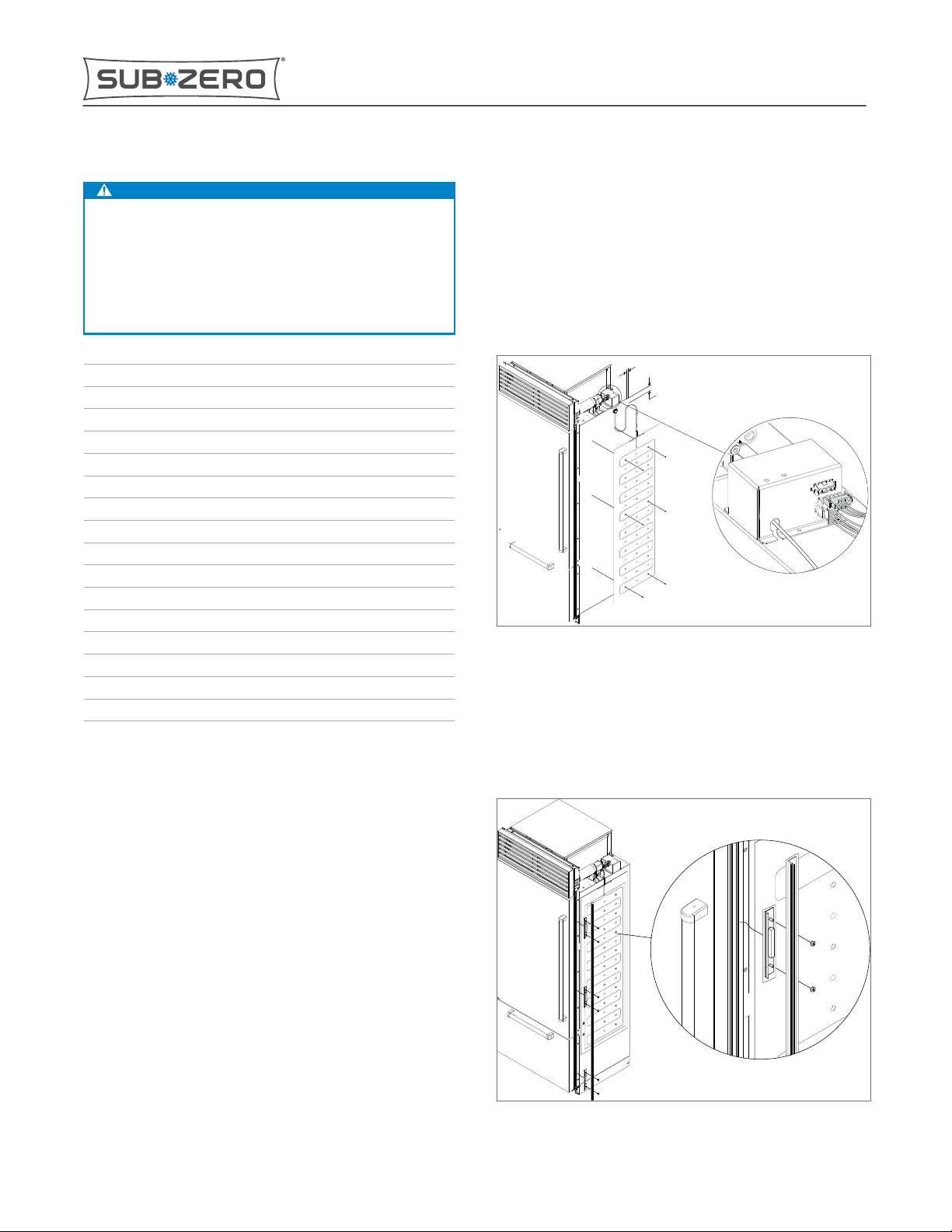
INSTALL THE HEATER
Note: The heater assembly MUST be attached to the right
4
2
ont leveling legs of
floor to complete
4
side of the left-hand unit.
Clear the foil from the mounting holes of the heater
1
assembly.
Built-In Series Dual Installation Kit
subzero.com 800.222.7820
Remove the four-prong safety plug from the panel-
6
mounted
the power cord box.
Connect the heater’s four-prong plug to the receptacle.
7
Attach the 5/16" × 1/2" plastic cord clip in a convenient
8
location near the water
Route the heater wires through the plastic cord clip and
9
any other available wire clips.
INSTALL THE CENTER TRIM
Note: Assemble the center trim piece and trim brackets
first, then attach the trim to the right-hand side of the lefthand unit.
Attach the three L-shaped dual trim bracket assemblies
1
to the dual install center trim piece using the nuts
pr
ovided. Do not tighten the nuts at this time.
four-prong receptacle at the rear side of
filter.
Place the heater against the right-hand side of the unit
2
with wires up and foil side in, positioning the heater 2”
(51 mm) from the top edge of the cabinet and 1” (25
mm) from the rear edge of the cabinet.
Using the heater as a template, mark the heater
3
mounting holes on the cabinet with a pencil, then
remove the heater.
Drill a 7/64" (3 mm) hole at each marked location.
4
Note: To avoid drilling through the inner liner, use a
short drill bit inserted into the drill chuck so that no
more than 1/2” (13 mm) to 3/4” (19 mm) of bit is
protruding.
Attach the heater to the unit using the #8-32 × 1/2" pan
5
head screws into the drilled holes.
7004565 REV. E 06/2018
Page 1 of 4
*7004565$REV.$E*
Page 2
Main
Frame
Center
T
rim
(Top View)
Main
Frame
Center
Trim
Built-In Series Dual Installation Kit
subzero.com 800.222.7820
With the trim brackets loosely attached, hold the center
2
trim piece at about a 75° angle against the right-hand
side main frame.
Rotate the center trim piece toward the unit so the trim
3
brackets hook in behind the main frame.
Align the bottom of the center trim piece with the
4
bottom of the main frame.
Tighten the nuts.
5
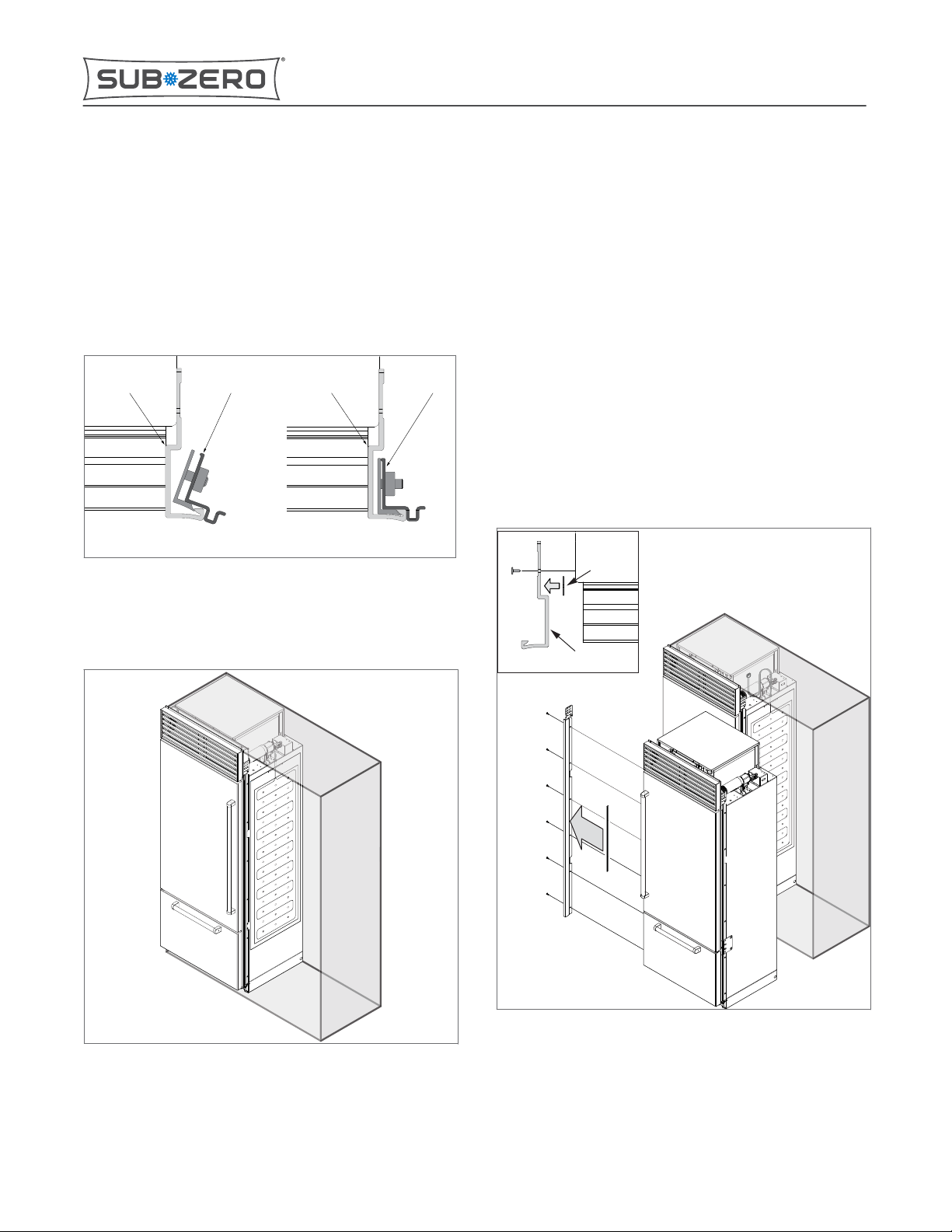
INSTALL THE UNIT INTO THE LEFT-HAND SIDE OF THE
ROUGH-IN OPENING
Install the unit into the left-hand side of the rough-in
opening as specified
in the installation guide.
INSTALL THE MAIN FRAME SHIM
Note: The shim assembly must be attached to the rear of
the left-hand side main frame of the right-hand unit.
Remove the left-side main frame from the right-hand
1
unit.
Remove the backing paper from the double-stick tape
2
that is attached to the main frame shim.
Align the shim to the main frame so the two holes in the
3
are at the same height as the two middle main
shim
frame mounting holes. Make sure the shim is tight to
the bend in the main frame, and the shim is in front of
the section of the main frame with the mounting holes.
Attach the shim to the main frame. Make sure the holes
4
in the shim are next to
but not over the main frame
mounting holes.
Reattach the left-side main frame to the right-hand unit.
5
Top View of
Main Frame
Shim
Left Main Frame
and Shim
Page 2 of 4
Page 3

1
/8”-1/4”
Bottom View of Bolts and Bracket
(Grilles removed
for clarity)
Tool Bolt
Tool Collar
Insert
Hexagonal Hole
Built-In Series Dual Installation Kit
subzero.com 800.222.7820
INSTALL THE SECOND UNIT TO THE RIGHT OF THE FIRST
Install, level, and align the unit until its main frame
bumps against the flange of the center trim piece, and
the bottom of the main frame aligns with the bottom of
the center trim piece.
Top View of
Main Frames
with Center
Trim Installed
INSTALL THE THREADED INSERTS AT THE TOP (FOR OVER/
UNDER MODELS)
Note: For all-refrigerator and all-freezer models, the
threaded inserts are already installed at the top. Skip these
instructions.
Open both grilles, and locate the hexagonal holes at
1
the top adjoining corners of the units (two for each
unit).
For each of the hexagonal holes:
2
a) Use a small screwdriver or similar tool to remove
the foam insulation from each hole to a depth of no
more than 1/2” (13 mm).
b) Screw the thread insert installation tool into a
threaded insert.
c) Position the threaded insert over one of the
hexagonal holes, and tap the threaded insert into
the hole.
d) Using a 1/2" wrench at the tool bolt top and a 9/16”
open-end wrench at the collar, spin the tool bolt
clockwise while holding the collar stationary. Stop
when it will spin no further.
e) Remove the tool from the insert.
JOIN THE UNITS TOGETHER AT THE BOTTOM
Using a 1/2" wrench, install or adjust the bolts at the
1
bottom adjoining cor
ners of the appliances so that
there is a 1/8" (3 mm) to 1/4” (6 mm) gap between the
bolt heads and the unit shell bottom.
▪
For All-Refrigerator and All-Freezer Models:
Loosen the four bolts (two for each unit).
▪
For Over/Under Models: Install four 5/16” × 3/4”
thread-forming screws (two for each unit).
Align the four notches of the dual-installation bottom
2
bracket with the four bolts at the bottom adjoining
corners of the appliances.
Push the bracket into position.
3
Tighten the bolts.
4
Page 3 of 4
Page 4

JOIN THE UNITS TOGETHER AT THE TOP
Working the dual-installation top bracket in from the
1
side, line up the holes of the top bracket with the
threaded inserts at the top adjoining corners of the
appliances.
Insert four 5/16-18 × 3/4” Tensilock bolts through the
2
bracket into the threaded inserts.
Tighten the bolts.
3
(Grilles
removed
for clarity)
Built-In Series Dual Installation Kit
subzero.com 800.222.7820
SECURE THE GRILLE FRAMES TOGETHER
Secure the grilles together by inserting the #10-24 ×
1
21/4" machine screw into the upper rear holes in the
grille brackets.
Attach the #10-24 nut to the machine screw, and
2
tighten it.
Close the grilles.
3
#10-24 × 21/4”
Machine Screw
#10-24 Nut
Front View
Page 4 of 4
 Loading...