

Page 1
D ESIGN G UIDE
Page 2

CONTENTS
Built-In Refrigeration 4– 30
Integrated Refrigeration 31– 49
Wine Storage 50– 66
Undercounter Refrigeration 67– 74
Warranty 75
Specifications are subject to change
without notice. Check our website,
www.subzero.com, for the most
up-to-date specifications.
SUB-ZERO®is a registered trademark of Sub-Zero Freezer Company, Inc.
The information and images in this
guide are the copyright property of
Sub-Zero Freezer Company, Inc.
Neither this book nor any information
or images contained herein may be
copied or used in whole or in part
without the express written permission
of Sub-Zero Freezer Company, Inc.
©Sub-Zero Freezer Company, Inc. all
rights reserved.
Page 3

WELCOME TO SUB-ZERO
We make the ultimate built-in, integrated and
undercounter refrigerators, freezers and wine
storage units. We offer more solutions to your
daily design problems of trying to work the
largest appliance into a home without being
obtrusive. Placing refrigeration in the home is no
longer a problem, but rather, an opportunity to
exercise your creativity.
Sub-Zero has rethought traditional built-in
refrigeration, a category it pioneered, with nearly
60 years of experience. When our complete line
of configurations— all refrigerator and all freezer,
over-and-under, or side-by-side— are coupled
with three design alternatives and classic,
platinum and carbon stainless steel finishes, the
result is unlimited flexibility in satisfying your
client‘s needs for residential refrigeration.
Created to blend invisibly into your home‘s
decor, the Integrated line lets you incorporate
refrigeration anywhere in the house— the kitchen,
master suite, media room or workout room.
These tall units or two-drawer base refrigerators,
freezers and combination units can be hidden
inside the furniture or cabinetry of your
choosing.
Sub-Zero is breaking with conventional ways of
offering Wine Storage for designers and their
clients. Our Built-In models offer unlimited
design and storage capabilities, along with the
free-standing Model 424FS.
Our reputation is legendary. We have engineered
and manufactured the best product in the
business, and we stand behind our product with
an unsurpassed warranty and a network of technicians to help you if service is necessary. See
SUB-ZERO
WARRANTY
details of our warranty at the end of this guide.
Comprehensive installation instructions are
shipped with each model. Refer to those instructions in preparing and installing all Sub-Zero
products; call Sub-Zero Freezer Company at
(800) 222-7820; or check our website at
www.subzero.com.
Sub-Zero products
are covered by a
two, five and twelve
year residential
warranty (exclusions
apply). See warranty
at the end of this
guide.
As you follow these instructions, you
will notice warning and caution symbols.
This blocked information is important
for the safe and efficient installation of
Sub-Zero equipment. There are two
types of potential hazards that may
occur during installation.
signals a situation where minor
injury or product damage may occur
if you do not follow instructions.
states a hazard that may cause
serious injury or death if precautions
are not followed.
Another footnote we would like to
identify is IMPORTANT NOTE: This
highlights information that is especially
relevant to a problem-free installation.
3
Page 4
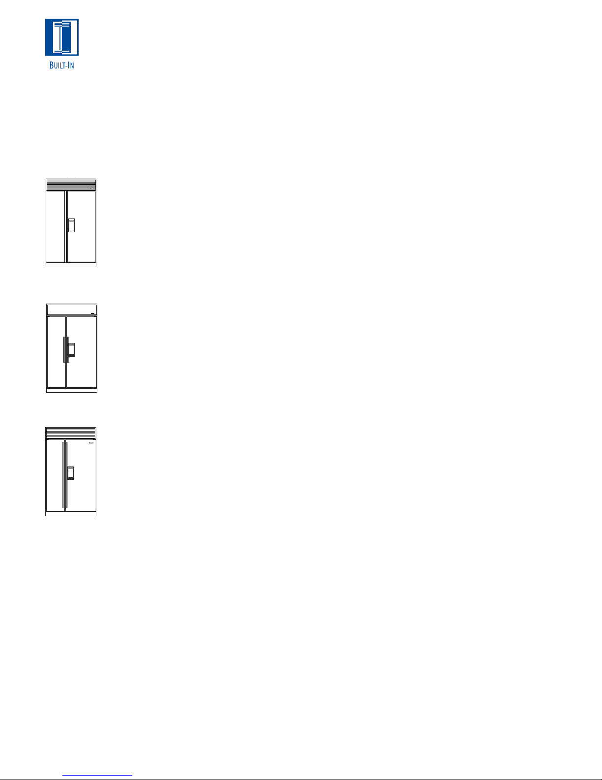
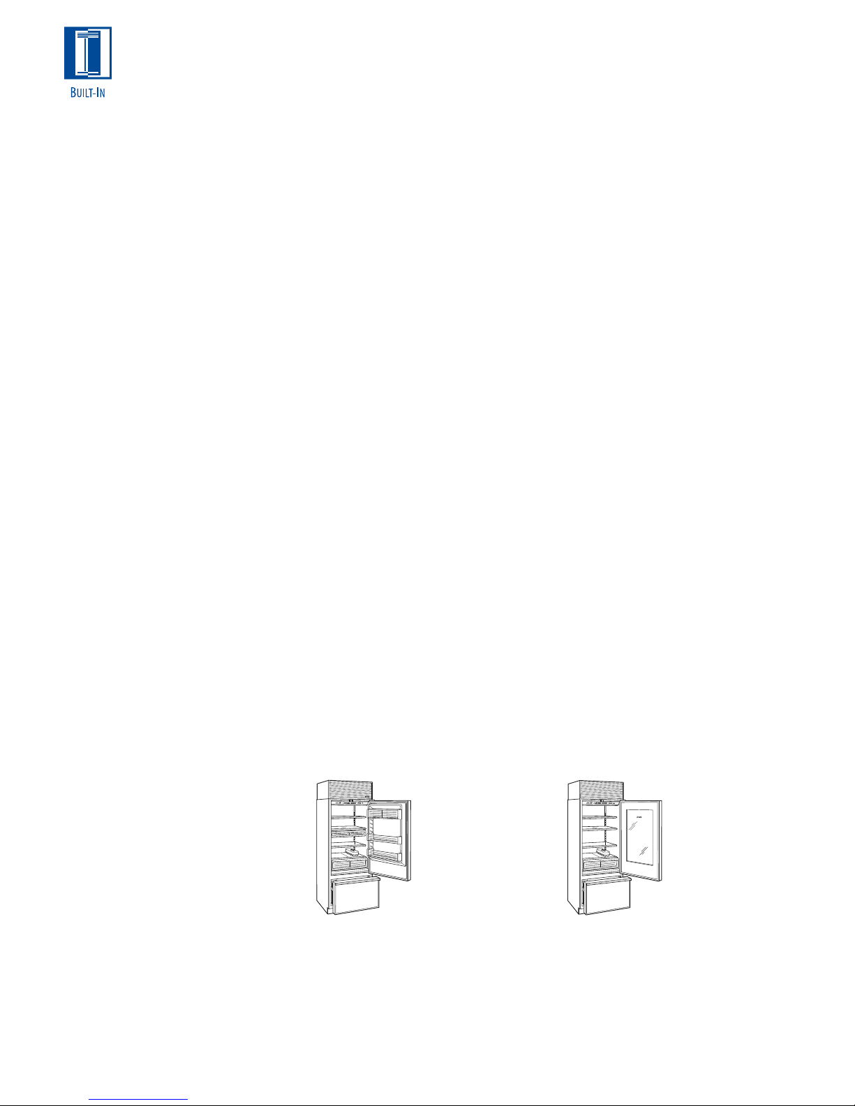
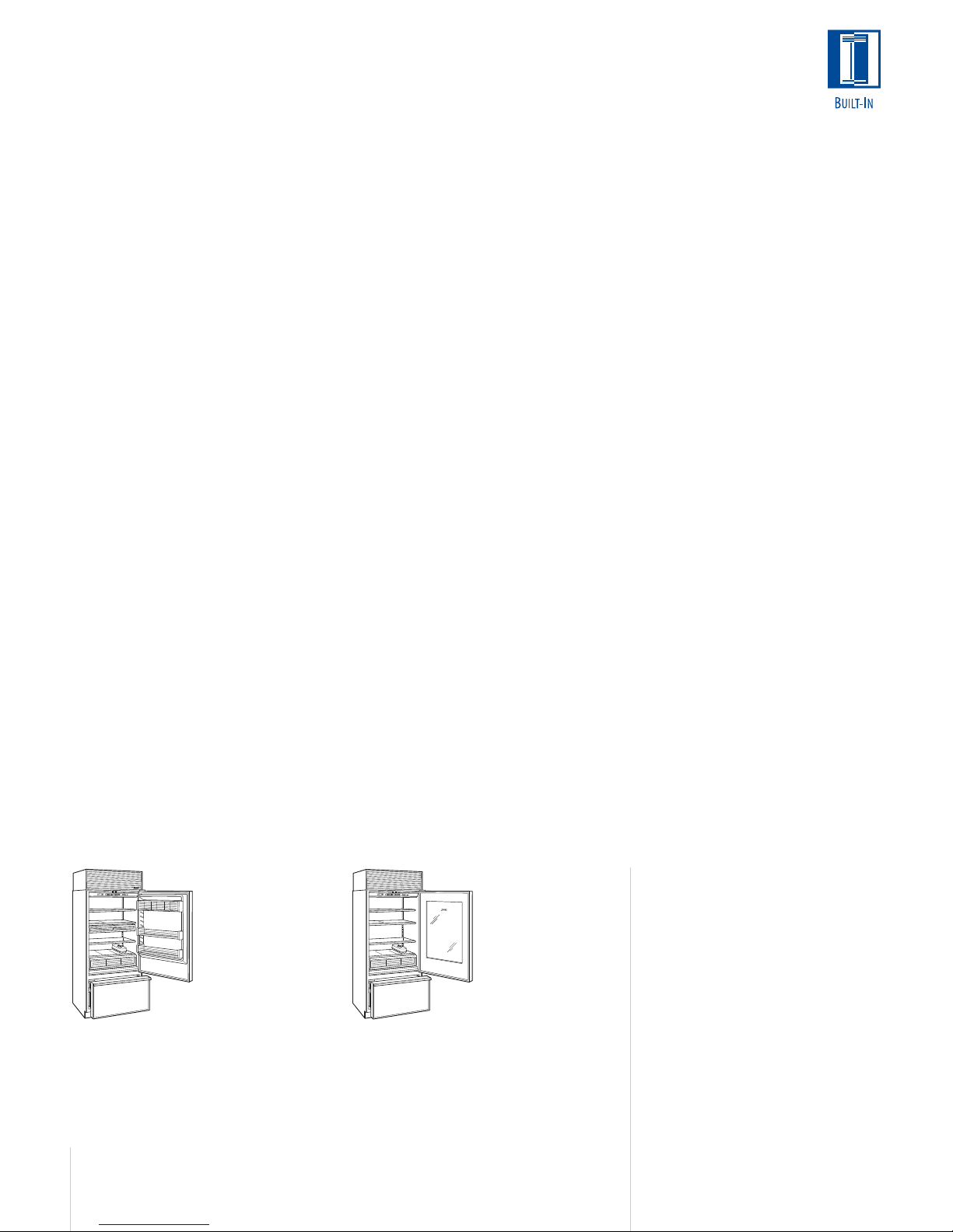
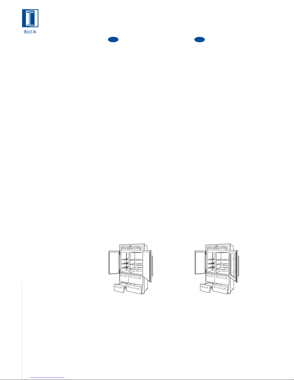
Model 695/F
()
Framed
Model 695/O
Overlay
BUILT-IN REFRIGERATION
Sub-Zero’s Built-In line offers you the most
complete set of design options in built-in refrigeration for all of its models, from the classic look
of the framed unit to the beauty of the overlay
models and the professional treatment of the
wrapped stainless steel doors.
Aside from the classic stainless steel, Sub-Zero
offers platinum and carbon premium stainless
steel finishes on its Built-In models and many
related accessories. The only exception to the
design alternatives are Models 648PRO and
648PROG, which are offered only in the stainless steel design application with the classic
finish. In addition, Models 685 and 695 are
offered in framed, overlay and classic stainless
steel (not platinum or carbon).
Glass doors are available on our Models 601R,
611 and 650. They each come in a framed,
overlay and stainless steel design. They all meet
stringent Department of Energy standards.
Model 648PROG also features a glass door in its
classic stainless steel look.
In the illustrations, we have shown the three
different design configurations of the framed,
overlay and stainless steel units applied to
Model 695. Please note how we qualify the
different looks with the model number.
The traditional framed units come with an
elegant full-length handle and an 11" (279)
louvered grille.
Overlay models will come with no handle
hardware, because the beauty of this design is
that you can match the surrounding cabinetry
hardware; however, we do offer optional handles
as sales accessories. The new ice and water
dispensing Models 685 and 695 will be able to
accept overlay panels. Overlay models will come
with a standard 11" (279) panel grille that will
accept decorative panel inserts. Models 601R,
601RG and 601F are only available with the
louvered grille. No panel grille option is available.
All stainless steel models, with the exception of
those mentioned earlier, are offered in the classic
stainless steel finish and in the premium finishes
of platinum and carbon. Stainless steel models
come with a standard 11" (279) heavy-duty
grille, 1" (25) diameter stainless steel handles
and a stainless steel kickplate.
All grilles will be offered as options in 1" (25)
increments from 10" (254) to 15" (381) and can
be ordered as sales accessories. Models
648PRO and 648PROG are the exception and
are available only with an 11" (279) grille.
An important step in assuring a successful plan
is to make sure that the actual equipment
shipped to your installation site matches the
design you have ordered. Each of these three
design options— framed, overlay and stainless
steel— has specific installation requirements,
which means it is vital that the unit match your
planning and space needs.
Model 695/S
Classic
Stainless Steel
4
Page 5
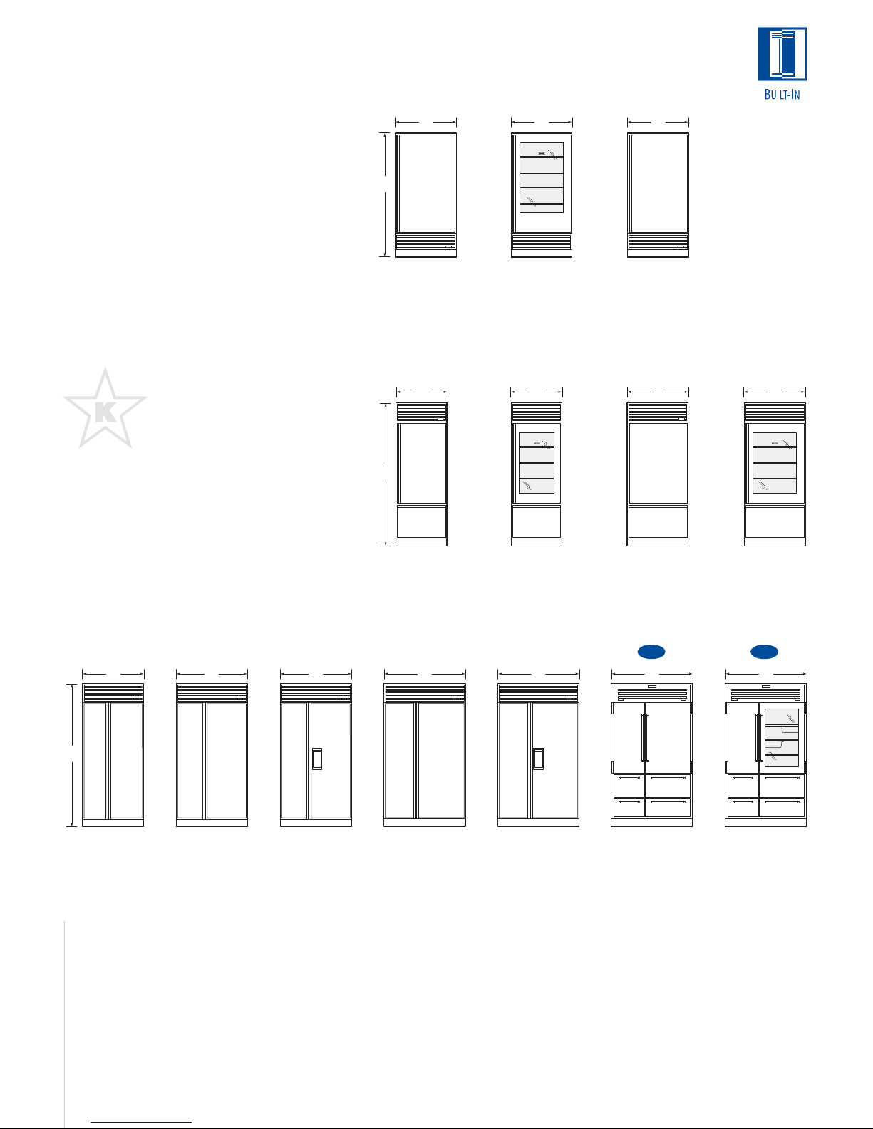
BUILT-IN REFRIGERATION
These illustrations represent the full line of
Sub-Zero Built-In models, shown in the framed
design application with louvered grille. Models
648PRO and 648PROG are available as freestanding or built-in units in classic stainless
steel only.
For information regarding specific Built-In
models, refer to the illustrations in this
section. Regardless of the specific design
application, framed, overlay or stainless steel,
the interior specifications of each model are
identical.
With the installation of a harness kit,
these appliances are Star-K compliant
to meet strict religious regulations in
conjunction with specific instructions
found on www.star-k.org. Models
648PRO and 648PROG are Star-K
certified from the factory with no
extra wiring harness required. For
details about the harness kit, contact
your Sub-Zero dealer.
ALL REFRIGERATOR | ALL FREEZER
36"
(914)
73"
(1854)
MODEL 601R
All Refrigerator
36"
(914)
MODEL 601RG
All Refrigerator
with Glass Door
Energy Star
Qualified
Energy Star
Qualified
OVER-AND-UNDER
84"
(2134)
30"
(762)
30"
(762)
36"
(914)
MODEL 601F
All Freezer
36"
(914)
36"
(914)
SIDE-BY-SIDE
84"
(2134)
36"
(914)
42"
(1067)
42"
(1067)
MODEL 661 MODEL 642 MODEL 685
Ice | Water
Dispensing
Comprehensive installation
instructions are shipped with each
model. Refer to those instructions
in preparing and installing all
Sub-Zero products; call Sub-Zero
Freezer Company at (800) 222-7820
or check our website at
www.subzero.com.
MODEL 611
MODEL 611G
with Glass Door
Energy Star
Qualified
48"
(1219)
48"
(1219)
MODEL 632 MODEL 695
Ice | Water
Dispensing
MODEL 650
Energy Star
Qualified
NEW NEW
48"
(1219)
MODEL 648PRO
Free-Standing
or Built-In
Available
Late Fall 2005
MODEL 650G
with Glass Door
48"
(1219)
MODEL 648PROG
Free-Standing
or Built-In
Available
Late Fall 2005
Dimensions in parentheses are in
millimeters unless otherwise specified.
5
Page 6

SUB-ZERO
WARRANTY
Sub-Zero products
are covered by a
two, five and twelve
year residential
warranty (exclusions
apply). See warranty
at the end of this
guide.
BUILT-IN FEATURES
Sub-Zero‘s design, beauty and quality are
reflected in the broad range of standard features
that put Sub-Zero in a class by itself.
Framed models for the classic look that made
Sub-Zero famous feature a louvered grille and
elegant full-length handle. An optional panel
grille is available for framed units, except for
Models 601R, 601RG and 601F. Optional panel
conversion kits are available for the new ice and
water dispensing Models 685 and 695, framed
application. See page 19 for details.
Overlay models blend seamlessly into your
overall room design and complement surrounding cabinetry. You get to add decorative
hardware. Overlay models will come with a panel
grille that will accept decorative panel inserts.
The new ice and water dispensing Models 685
and 695 are also available in the overlay application.
Stainless steel models feature wrapped doors,
1" (25) diameter stainless steel handles and
heavy-duty grille designed specifically to
enhance the aesthetics of the professional look
of kitchens today. All Built-In stainless steel
models are offered in the classic stainless steel
finish and in the premium finishes of platinum
and carbon, except for Models 685, 695,
648PRO and 648PROG, which are offered in the
classic stainless steel finish only. The premium
finishes are treated as special orders and must
be ordered 90 days before you expect delivery.
Dual Refrigeration System. All Built-In combination models have the exclusive Sub-Zero dual
refrigeration system, which ensures the freshest
food and energy efficiency at the same time. You
have precise independent control of the refrigerator and freezer compartments.
Glass Door. Model 601RG is an all refrigerator
unit featuring a glass door. Models 611G and
650G are over-and-under combination units
where the refrigerator has a glass door. These
glass door models come in framed, overlay and
stainless steel designs and meet stringent
Department of Energy standards. The Model
648PROG side-by-side unit features a glass door
on the refrigerator side and comes in classic
stainless steel only.
Ice and Water Dispensing. Models 685 and 695
feature a dispenser that gives you both ice and
chilled water through the refrigerator door.
Fresh Food. High humidity crisper drawer with
removable dividers is large and deep, with
smooth sides for easy cleaning.
Electronic Controls. Controls are up front and
easy to use. They give you digital readings for
quick, easy-to-read reference. The microprocessor gives you better control, automatic
defrosting that senses, then adapts to your use
patterns, and a vacuum condenser indicator
light.
Improved Lighting. Bright lighting spreads even
illumination throughout the compartment and
conceals the source.
Door Shelves. All door shelves are adjustable for
complete flexibility and convenience.
Spill-Proof Shelves. Cantilevered shelves make
repositioning quick and easy. They are easy to
clean and spill-proof. They’re steel reinforced to
provide durability and reliability.
Dairy Storage. Dairy compartment is adjustable,
with easy, one-door access, compartment
dividers and a clean design. The dairy shelf is
magnetically sealed to maintain freshness.
Automatic Ice. Ice maker provides high-quality,
crescent-shaped ice that won‘t stick to the side
of the glass.
Built-In Look. Shallow-depth design means
access is easy to any area of the refrigerator.
Tight Seal. Magnetic gaskets around all doors
give extra-tight seals.
Energy Efficient. Our solid core doors improve
insulation and structural integrity and help us
exceed tough DOE Energy Standards.
Kickplate. Solid, adjustable kickplate gives a true
built-in look and conforms to American Institute
of Architects standards.
6
Dimensions in parentheses are in
millimeters unless otherwise specified.
Page 7
MODEL 601R
ALL REFRIGERATOR
Energy Star Qualified
MODEL 601RG
ALL REFRIGERATOR
WITH GLASS DOOR
Energy Star Qualified
MODEL 601F
ALL FREEZER
MODEL OPTIONS
Framed Design 601R/F
Overlay Design 601R/O
Classic Stainless Steel 601R/S
Platinum Stainless Steel 601R/P
Carbon Stainless Steel 601R/B
SPECIFICATIONS
Overall Width 36" (914)
Overall Height 73" (1854)
Overall Depth 24" (610)
Refrigerator Capacity 19.9 cu ft (564 L)
Min Height Required 72
Door Swing Clearance 36
3
/4" (1848)
1
/16" (916)
Specify Door Swing LH or RH
Annual Energy Usage 399 kWh | $34*
Shipping Wt (F) 391 lbs (177 kg)
Shipping Wt (O) 391 lbs (177 kg)
Shipping Wt (S/P/B) 420 lbs (191 kg)
REFRIGERATOR FEATURES
4 Adjustable Glass Shelves
1 Stationary Glass Shelf
High Humidity Compartment w/ Dividers
Adjustable Roll-Out Deli Basket
3 Adjustable Door Shelves
Adjustable Dairy Compartment
Egg Container
MODEL OPTIONS
Framed Design 601RG/F
Overlay Design 601RG/O
Classic Stainless Steel 601RG/S
Platinum Stainless Steel 601RG/P
Carbon Stainless Steel 601RG/B
SPECIFICATIONS
Overall Width 36" (914)
Overall Height 73" (1854)
Overall Depth 24" (610)
Refrigerator Capacity 20.1 cu ft (569 L)
Min Height Required 72
Door Swing Clearance 36
3
/4" (1848)
1
/16" (916)
Specify Door Swing LH or RH
Annual Energy Usage 400 kWh | $34*
Shipping Wt (F) 400 lbs (181 kg)
Shipping Wt (O) 400 lbs (181 kg)
Shipping Wt (S/P/B) 430 lbs (195 kg)
REFRIGERATOR FEATURES
4 Adjustable Glass Shelves
1 Stationary Glass Shelf
High Humidity Compartment w/ Dividers
Triple-Pane UV Resistant Glass Door
Optional Roll-Out Deli Basket Available
Egg Container
Optional High Altitude Glass Available**
MODEL OPTIONS
Framed Design 601F/F
Overlay Design 601F/O
Classic Stainless Steel 601F/S
Platinum Stainless Steel 601F/P
Carbon Stainless Steel 601F/B
SPECIFICATIONS
Overall Width 36" (914)
Overall Height 73" (1854)
Overall Depth 24" (610)
Freezer Capacity 19.3 cu ft (547 L)
Min Height Required 72
Door Swing Clearance 36
3
/4" (1848)
1
/16" (916)
Specify Door Swing LH or RH
Annual Energy Usage 737 kWh | $62*
Shipping Wt (F) 378 lbs (171 kg)
Shipping Wt (O) 378 lbs (171 kg)
Shipping Wt (S/P/B) 406 lbs (184 kg)
FREEZER FEATURES
Automatic Ice Maker
3 Adjustable Wire Shelves
1 Stationary Glass Shelf
3 Freezer Storage Drawers
5 Adjustable Door Shelves
MODEL 601R MODEL 601RG MODEL 601F
*Annual energy costs are based on
8.29 cents per kilowatt hour.
**High altitude glass doors are
for installations at or above 5,000'
(1524 m) in elevation.
All models are shown in the framed
design application.
ACCESSORIES
Contact your Sub-Zero Dealer
Front panels for framed design
in white, almond and classic
stainless steel
Side panels for framed or
stainless steel design in white,
almond and classic stainless steel
Extended framed handles
Decorative overlay handles
7
Page 8
MODEL 611
OVER-AND-UNDER
Energy Star Qualified
MODEL 611G
OVER-AND-UNDER
WITH GLASS DOOR
*Annual energy costs are based on
8.29 cents per kilowatt hour.
**High altitude glass doors are
for installations at or above 5,000'
(1524 m) in elevation.
All models are shown in the framed
design application.
MODEL OPTIONS
Framed Design 611/F
Overlay Design 611/O
Classic Stainless Steel 611/S
Platinum Stainless Steel 611/P
Carbon Stainless Steel 611/B
SPECIFICATIONS
Overall Width 30" (762)
Overall Height 84" (2134)
Overall Depth 24" (610)
Refrigerator Capacity 12.7 cu ft (360 L)
Freezer Capacity 3.9 cu ft (110 L)
Min Height Required 83" (2108)
Door Swing Clearance 30
1
/8" (765)
Annual Energy Usage 463 kWh | $39*
Shipping Wt (F) 430 lbs (195 kg)
Shipping Wt (O) 430 lbs (195 kg)
Shipping Wt (S/P/B) 462 lbs (210 kg)
REFRIGERATOR (DOOR)
3 Adjustable Glass Shelves
1 Stationary Glass Shelf
High Humidity Compartment w/ Divider
Adjustable Roll-Out Deli Basket
2 Adjustable Door Shelves
Adjustable Dairy Compartment
Egg Container
MODEL OPTIONS
Framed Design 611G/F
Overlay Design 611G/O
Classic Stainless Steel 611G/S
Platinum Stainless Steel 611G/P
Carbon Stainless Steel 611G/B
SPECIFICATIONS
Overall Width 30" (762)
Overall Height 84" (2134)
Overall Depth 24" (610)
Refrigerator Capacity 12.9 cu ft (365 L)
Freezer Capacity 3.9 cu ft (110 L)
Min Height Required 83" (2108)
Door Swing Clearance 30
1
/8" (765)
Annual Energy Usage 544 kWh | $46*
Shipping Wt (F) 471 lbs (214 kg)
Shipping Wt (O) 471 lbs (214 kg)
Shipping Wt (S/P/B) 476 lbs (216 kg)
REFRIGERATOR (DOOR)
3 Adjustable Glass Shelves
1 Stationary Glass Shelf
High Humidity Compartment w/ Divider
Triple-Pane UV Resistant Glass Door
Optional Roll-Out Deli Basket Available
Egg Container
Optional High Altitude Glass Available**
FREEZER (DRAWER)
Automatic Ice Maker
Two-Tier Pull Out Drawer
MODEL 611 MODEL 611G
8
FREEZER (DRAWER)
Automatic Ice Maker
Two-Tier Pull Out Drawer
Page 9
MODEL 650
OVER-AND-UNDER
Energy Star Qualified
MODEL 650G
OVER-AND-UNDER
WITH GLASS DOOR
MODEL OPTIONS
Framed Design 650/F
Overlay Design 650/O
Classic Stainless Steel 650/S
Platinum Stainless Steel 650/P
Carbon Stainless Steel 650/B
SPECIFICATIONS
Overall Width 36" (914)
Overall Height 84" (2134)
Overall Depth 24" (610)
Refrigerator Capacity 15.7 cu ft (445 L)
Freezer Capacity 4.9 cu ft (139 L)
Min Height Required 83" (2108)
Door Swing Clearance 36
1
/16" (916)
Annual Energy Usage 481 kWh | $40*
Shipping Wt (F) 482 lbs (219 kg)
Shipping Wt (O) 482 lbs (219 kg)
Shipping Wt (S/P/B) 515 lbs (234 kg)
REFRIGERATOR (DOOR)
3 Adjustable Glass Shelves
1 Stationary Glass Shelf
High Humidity Compartment w/ Dividers
Adjustable Roll-Out Deli Basket
2 Adjustable Door Shelves
Adjustable Dairy Compartment
Egg Container
MODEL OPTIONS
Framed Design 650G/F
Overlay Design 650G/O
Classic Stainless Steel 650G/S
Platinum Stainless Steel 650G/P
Carbon Stainless Steel 650G/B
SPECIFICATIONS
Overall Width 36" (914)
Overall Height 84" (2134)
Overall Depth 24" (610)
Refrigerator Capacity 16.0 cu ft (453 L)
Freezer Capacity 4.9 cu ft (139 L)
Min Height Required 83" (2108)
Door Swing Clearance 36
1
/16" (916)
Annual Energy Usage 565 kWh | $47*
Shipping Wt (F) 523 lbs (237 kg)
Shipping Wt (O) 523 lbs (237 kg)
Shipping Wt (S/P/B) 529 lbs (240 kg)
REFRIGERATOR (DOOR)
3 Adjustable Glass Shelves
1 Stationary Glass Shelf
High Humidity Compartment w/ Dividers
Triple-Pane UV Resistant Glass Door
Optional Roll-Out Deli Basket Available
Egg Container
Optional High Altitude Glass Available**
FREEZER (DRAWER)
Automatic Ice Maker
Two-Tier Pull Out Drawer
MODEL 650
Dimensions in parentheses are in
millimeters unless otherwise specified.
FREEZER (DRAWER)
Automatic Ice Maker
Two-Tier Pull Out Drawer
MODEL 650G
ACCESSORIES
Contact your Sub-Zero Dealer
Front and grille panels for framed
design in white, almond and
classic stainless steel
Side panels for framed or
stainless steel design in white,
almond and classic stainless steel
Louvered, panel or stainless steel
grilles in 1" (25) increments from
10" (254) to 15" (381) high*
Extended framed handles
Decorative overlay handles
*Accessory is not available for
every model.
9
Page 10
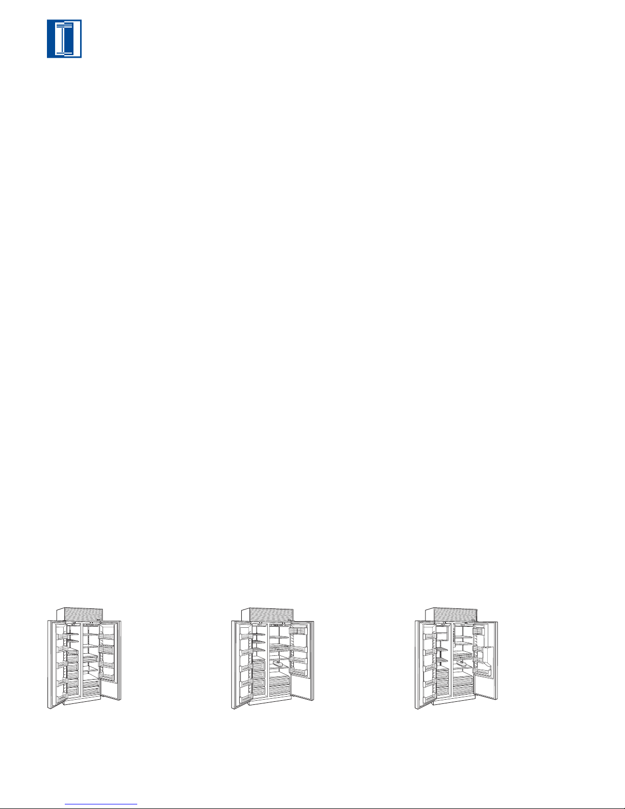
MODEL 661
SIDE-BY-SIDE
MODEL 642
SIDE-BY-SIDE
MODEL 685
SIDE-BY-SIDE
ICE/WATER DISPENSING
MODEL OPTIONS
Framed Design 661/F
Overlay Design 661/O
Classic Stainless Steel 661/S
Platinum Stainless Steel 661/P
Carbon Stainless Steel 661/B
SPECIFICATIONS
Overall Width 36" (914)
Overall Height 84" (2134)
Overall Depth 24" (610)
Refrigerator Capacity 12.5 cu ft (354 L)
Freezer Capacity 8.8 cu ft (249 L)
Min Height Required 83" (2108)
Door Swing Clearance 20
3
/4" (527)
Annual Energy Usage 636 kWh | $53*
Shipping Wt (F) 500 lbs (227 kg)
Shipping Wt (O) 500 lbs (227 kg)
Shipping Wt (S/P/B) 538 lbs (244 kg)
REFRIGERATOR FEATURES
4 Adjustable Glass Shelves
1 Stationary Glass Shelf
High Humidity Compartment
1 Storage Drawer
Adjustable Roll-Out Deli Basket
3 Adjustable Door Shelves
Adjustable Dairy Compartment
Egg Container
MODEL OPTIONS
Framed Design 642/F
Overlay Design 642/O
Classic Stainless Steel 642/S
Platinum Stainless Steel 642/P
Carbon Stainless Steel 642/B
SPECIFICATIONS
Overall Width 42" (1067)
Overall Height 84" (2134)
Overall Depth 24" (610)
Refrigerator Capacity 16.2 cu ft (459 L)
Freezer Capacity 8.2 cu ft (232 L)
Min Height Required 83" (2108)
Door Swing Clearance 25
9
/16" (649)
Annual Energy Usage 650 kWh | $54*
Shipping Wt (F) 541 lbs (245 kg)
Shipping Wt (O) 541 lbs (245 kg)
Shipping Wt (S/P/B) 582 lbs (264 kg)
REFRIGERATOR FEATURES
4 Adjustable Glass Shelves
1 Stationary Glass Shelf
High Humidity Compartment
1 Storage Drawer
Adjustable Roll-Out Deli Basket
3 Adjustable Door Shelves
Adjustable Dairy Compartment
Egg Container
MODEL OPTIONS
Framed Design 685/F
Overlay Design 685/O
Classic Stainless Steel 685/S
SPECIFICATIONS
Overall Width 42" (1067)
Overall Height 84" (2134)
Overall Depth 24" (610)
Refrigerator Capacity 15.6 cu ft (442 L)
Freezer Capacity 8.2 cu ft (232 L)
Min Height Required 83" (2108)
Door Swing Clearance 25
9
/16" (649)
Annual Energy Usage 694 kWh | $58*
Shipping Wt (F) 569 lbs (258 kg)
Shipping Wt (O) 569 lbs (258 kg)
Shipping Wt (S) 608 lbs (276 kg)
REFRIGERATOR FEATURES
4 Adjustable Glass Shelves
1 Stationary Glass Shelf
High Humidity Compartment
1 Storage Drawer
Adjustable Roll-Out Deli Basket
3 Adjustable Door Shelves
Adjustable Dairy Compartment
Egg Container
FREEZER FEATURES
FREEZER FEATURES
Automatic Ice Maker
2 Adjustable Wire Shelves
1 Stationary Solid Shelf
4 Storage Drawers
Automatic Ice Maker
3 Adjustable Wire Shelves
1 Stationary Solid Shelf
3 Storage Drawers
5 Adjustable Door Shelves
5 Adjustable Door Shelves
MODEL 661 MODEL 642 MODEL 685
10
FREEZER FEATURES
Automatic Ice Maker
2 Adjustable Wire Shelves
1 Stationary Wire Shelf
3 Storage Drawers
5 Adjustable Door Shelves
2 Juice Can Shelves
Page 11
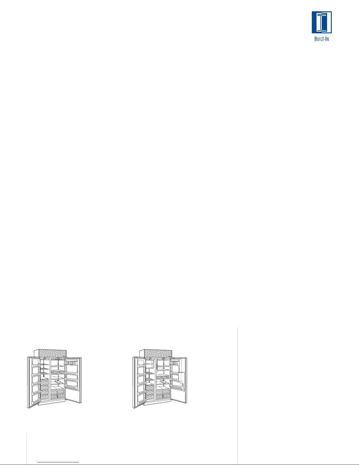
MODEL 632
SIDE-BY-SIDE
MODEL 695
SIDE-BY-SIDE
ICE/WATER DISPENSING
MODEL OPTIONS
Framed Design 632/F
Overlay Design 632/O
Classic Stainless Steel 632/S
Platinum Stainless Steel 632/P
Carbon Stainless Steel 632/B
SPECIFICATIONS
Overall Width 48" (1219)
Overall Height 84" (2134)
Overall Depth 24" (610)
Refrigerator Capacity 18.9 cu ft (535 L)
Freezer Capacity 9.8 cu ft (278 L)
Min Height Required 83" (2108)
Door Swing Clearance 29
1
/4" (743)
Annual Energy Usage 675 kWh | $56*
Shipping Wt (F) 582 lbs (264 kg)
Shipping Wt (O) 582 lbs (264 kg)
Shipping Wt (S/P/B) 630 lbs (286 kg)
REFRIGERATOR FEATURES
4 Adjustable Glass Shelves
1 Stationary Glass Shelf
High Humidity Compartment w/ Divider
2 Storage Drawers
Adjustable Roll-Out Deli Basket
3 Adjustable Door Shelves
Adjustable Dairy Compartment
Egg Container
MODEL OPTIONS
Framed Design 695/F
Overlay Design 695/O
Classic Stainless Steel 695/S
SPECIFICATIONS
Overall Width 48" (1219)
Overall Height 84" (2134)
Overall Depth 24" (610)
Refrigerator Capacity 18.2 cu ft (515 L)
Freezer Capacity 9.8 cu ft (278 L)
Min Height Required 83" (2108)
Door Swing Clearance 29
1
/4" (743)
Annual Energy Usage 747 kWh | $62*
Shipping Wt (F) 610 lbs (277 kg)
Shipping Wt (O) 610 lbs (277 kg)
Shipping Wt (S) 656 lbs (298 kg)
REFRIGERATOR FEATURES
4 Adjustable Glass Shelves
1 Stationary Glass Shelf
High Humidity Compartment w/ Divider
2 Storage Drawers
Adjustable Roll-Out Deli Basket
3 Adjustable Door Shelves
Adjustable Dairy Compartment
Egg Container
*Annual energy costs are based on
8.29 cents per kilowatt hour.
All models are shown in the framed
design application.
FREEZER FEATURES
Automatic Ice Maker
3 Adjustable Wire Shelves
1 Stationary Solid Shelf
3 Storage Drawers
5 Adjustable Door Shelves
FREEZER FEATURES
Automatic Ice Maker
2 Adjustable Wire Shelves
1 Stationary Wire Shelf
3 Storage Drawers
5 Adjustable Door Shelves
2 Juice Can Shelves
MODEL 632 MODEL 695
Dimensions in parentheses are in
millimeters unless otherwise specified.
ACCESSORIES
Contact your Sub-Zero Dealer
Front and grille panels for framed
design in white, almond and
classic stainless steel
Side panels for framed or
stainless steel design in white,
almond and classic stainless steel
Louvered, panel or stainless steel
grilles in 1" (25) increments from
10" (254) to 15" (381) high
Extended framed handles
Decorative overlay handles
*Accessory is not available for
every model.
11
Page 12
MODEL 648PRO
NEW
Available Late Fall 2005
SIDE-BY-SIDE
BUILT-IN OR FREE-STANDING
MODEL 648PROG
NEW
Available Late Fall 2005
SIDE-BY-SIDE
WITH GLASS DOOR
BUILT-IN OR FREE-STANDING
*Annual energy costs are based on
8.29 cents per kilowatt hour.
**High altitude glass doors are
for installations at or above 5,000'
(1524 m) in elevation.
All models are shown in the framed
design application.
SPECIFICATIONS
Overall Width 48" (1219)
Overall Height 84" (2134)
Overall Depth 25
7
/8" (657)
Refrigerator Capacity 18.4 cu ft (521 L)
Freezer Capacity 11.7 cu ft (331 L)
Min Height Required 83
Door Swing Clearance 28
1
/2" (2121)
3
/4" (730)
Annual Energy Usage 689 kWh | $ 58*
Shipping Weight 860 lbs (390 kg)
REFRIGERATOR
(DOOR AND TWO DRAWERS)
3 Adjustable Glass Shelves
1 Stationary Glass Shelf
2 Adjustable Slide-Out Stainless Steel Bins
1 Crisper Lid
Dividers for Drawers Included
FREEZER
(DOOR AND TWO DRAWERS)
Automatic Ice Maker
Water Filtration Filter
3 Adjustable Stainless Steel Shelves
1 Stationary Stainless Steel Shelf
1 Stainless Steel Ice Bucket
SPECIFICATIONS
Overall Width 48" (1219)
Overall Height 84" (2134)
Overall Depth 25
7
/8" (657)
Refrigerator Capacity 18.4 cu ft (521 L)
Freezer Capacity 11.7 cu ft (331 L)
Min Height Required 83
Door Swing Clearance 28
1
/2" (2121)
3
/4" (730)
Annual Energy Usage 689 kWh | $ 58*
Shipping Weight 875 lbs (397 kg)
REFRIGERATOR
(DOOR AND TWO DRAWERS)
3 Adjustable Glass Shelves
1 Stationary Glass Shelf
2 Adjustable Slide-Out Stainless Steel Bins
1 Crisper Lid
Dividers for Drawers Included
Triple-Pane UV Resistant Glass Door
Optional High Altitude Glass Available**
FREEZER
(DOOR AND TWO DRAWERS)
Automatic Ice Maker
Water Filtration Filter
3 Adjustable Stainless Steel Shelves
1 Stationary Stainless Steel Shelf
1 Stainless Steel Ice Bucket
ACCESSORIES
Contact your Sub-Zero Dealer
90 degree door stop kit— right
or left hinge (DS90PRO)
Dozen egg container with lid
(EGGTRAY)
Slide-out refrigerator bin
(SLIDEBIN)
Stainless steel side panel (SP648)
Free-standing kit (FSK648)—
includes two stainless steel side
panels and top lid
12
MODEL 648PRO MODEL 648PROG
Page 13

PLANNING INFORMATION
Although the Sub-Zero Built-In line offers a wide
range of designs and configurations, the basic
planning considerations for all models have
much in common. As you integrate Built-In
models into your overall plan, review installation
requirements for your particular model(s). The
Installation Specifications illustrations provide
planning information for all Built-In models—
framed, overlay and stainless steel.
Allow the door(s) to open a minimum of 90˚ or
you‘ll have problems removing drawers. With the
door opening at 90˚, you may have to move
drawers slightly to clear the door interior.
For corner installations, allow for a minimum 3"
(76) filler so that the door can open to 90˚. If
you‘re using raised panels, consider using a
wider filler.
When units are installed side by side, a filler strip
is recommended. The width of this filler strip will
vary depending on the configuration and panels
you use.
Be sure to add the filler strip width to your
finished rough opening dimension. In any
installation of two units side by side without a
filler strip, add an additional 1/2" (13) to your
combined numbers. This will allow for the
proper width.
IMPORTANT NOTE: Refer to the full-scale illustrations at the end of this section for specifics
on door openings and filler size alternatives.
ELECTRICAL REQUIREMENTS
A 115 V AC, 60 Hz, 15 amp circuit breaker and
electrical supply are required. A separate circuit,
servicing only this appliance, is required.
All Sub-Zero Built-In models are equipped with a
power supply cord with a 3-prong grounding
plug, which must be plugged into a mating
3-prong grounding-type wall receptacle. Follow
the National Electrical Code and local codes and
ordinances when installing the receptacle. Refer
to the Installation Specifications illustration for
your model on the following pages.
IMPORTANT NOTE: A ground fault circuit
interrupter (GFCI) is not recommended and may
cause interruption of operation.
PLUMBING CONSIDERATIONS
For Built-In models with an automatic ice maker,
rough in the water supply line. Connect a 1/4"
OD copper line to the house supply, being sure
to use an easily accessible shut-off valve
between the supply and the refrigerator.
Do not use self-piercing valves. A saddle valve
kit (4200880) is available from your Sub-Zero
dealer.
For Built-In models except Model 648PRO and
648PROG, a line filter is required when water
conditions have a high sediment content. The
ice maker operates on water pressure of 20 psi
(1.4 bar) to 100 psi (6.9 bar).
IMPORTANT NOTE: In some cases a reverse
osmosis water filter system may not be able to
maintain the minimum water pressure consistently.
Models 648PRO and 648PROG come with an
automatic ice maker and an integrated water
filtration system. This system operates on water
pressure between 35 psi (2.4 bar) and 120 psi
(8.3 bar).
IMPORTANT NOTE: A reverse osmosis system
can be used with Models 648PRO and
648PROG, provided there is constant water
pressure of 20 psi (1.4 bar) to 120 psi (8.3 bar)
supplied to the unit at all times. In this application, the integrated water filtration system must
be set to bypass mode. This is achieved by
removing the water filter cartridge. Refer to the
PRO 48 Installation Guide packed with the unit
for detailed instructions.
The water line should be routed up through the
floor within 1/2" (13) from the back wall and no
higher than 3" (76) off the floor. If you have to
come through the wall, make sure the water line
is no more than 3" (76) from the floor.
Regardless of the routing, allow 3' (1 m) of
excess copper tubing to remain outside the wall
or floor for easy connection to the unit. Refer to
Installation Specification illustrations.
MODEL OPTIONS
Model 601R
36" (914)
All Refrigerator
Model 601RG
36" (914)
All Refrigerator
with Glass Door
Model 601F
36" (914)
All Freezer
Model 611
30" (762)
Over-and-Under
Model 611G
30" (762)
Over-and-Under
with Glass Door
Model 650
36" (914)
Over-and-Under
Model 650G
36" (914)
Over-and-Under
with Glass Door
Model 661
36" (914)
Side-by-Side
Model 642
42" (1067)
Side-by-Side
Model 685
42" (1067)
Side-by-Side
Ice | Water Dispensing
Model 632
48" (1219)
Side-by-Side
Model 695
48" (1219)
Side-by-Side
Ice | Water Dispensing
Model 648PRO
48" (1219)
Side-by-Side
Free-Standing
Model 648PROG
48" (1219)
Side-by-Side
with Glass Door
Free-Standing
Dimensions in parentheses are in
millimeters unless otherwise specified.
13
Page 14
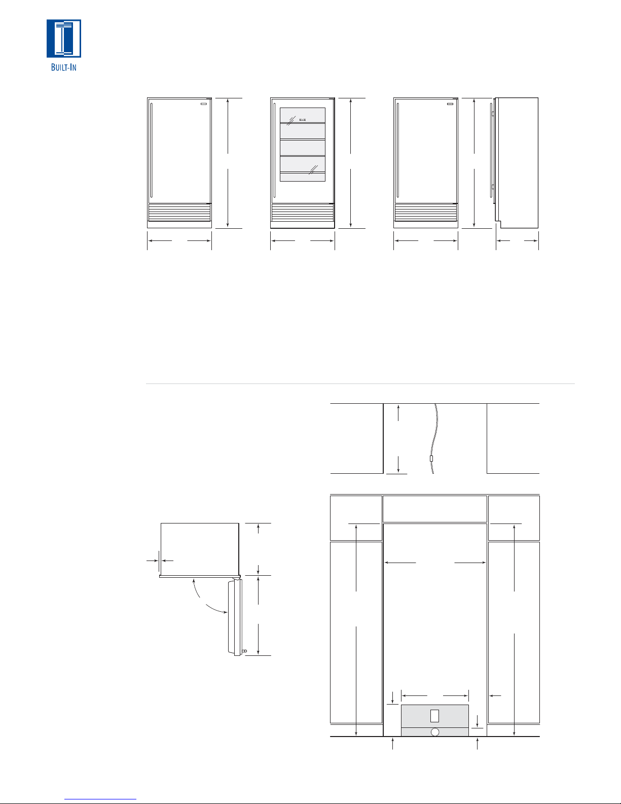
OVERALL DIMENSIONS
All Refrigerator | All Freezer Models
ALL REFRIGERATOR
ALL FREEZER
Model 601R
All Refrigerator
Model 601RG
All Refrigerator
with Glass Door
Model 601F
All Freezer
INSTALLATION
Refer to the
installation instructions shipped with
each Sub-Zero
product for detailed
specifications.
Refer to the fullscale illustrations at
the end of this
section for specifics
on door openings
and other specifications.
73"
(1854)
36"
(914)
Model 601R
All Refrigerator
36"
(914)
Model 601RG
All Refrigerator
with Glass Door
Width 36" (914)
Height 73" (1854)
Depth 24" (610)
Width 36" (914)
Height 73" (1854)
Depth 24" (610)
Illustrations shown in stainless steel design.
INSTALLATION SPECIFICATIONS
All Refrigerator | All Freezer Models
Models 601R and 601RG will not require the
water line connection.
Dimensions are for finished rough openings.
Door swing clearances are based on
stainless steel door and handle dimensions.
3
/8"(10)
FRAME
EXTENSION
237/8"
(606)
BEHIND
FRAME
73"
(1854)
36"
(914)
Model 601F
All Freezer
Width 36" (914)
Height 73" (1854)
Depth 24" (610)
24"
(610)
ROUGH
OPENING
DEPTH
ROUGH OPENING WIDTH
APPROX 36" (914)
FROM BACK WALL
SHUT-OFF
VALV E
TOP VIEW
351/2" (902)
WATER LINE
(601F ONLY)
EXTEND
73"
(1854)
24"
(610)
90˚
14
361/4"
(916)
723/4" (1848)
ROUGH OPENING
HEIGHT TO
FINISHED
FLOORING
LOCATE ELECTRICAL
WITHIN ENTIRE SHADED AREA
LOCATE WATER SUPPLY
WITHIN BOTTOM SHADED
AREA ONLY (601F ONLY)
24"
(610)
11"
(279)
E
W
FRONT VIEW
6"
(152)
3"
(76)
723/4" (1848)
MINIMUM HEIGHT
REQUIRED TO
FINISHED
FLOORING
(LEVELERS IN)
Page 15
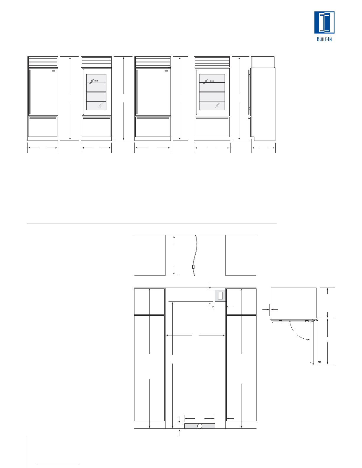
OVERALL DIMENSIONS
Over-and-Under Models
84"
(2134)
84"
(2134)
84"
(2134)
84"
(2134)
OVER-AND-UNDER
Model 611
Model 611G
with Glass Door
Model 650
Model 650G
with Glass Door
30"
(762)
Model 611
30"
(762)
Model 611G
with Glass Door
Width 30" (762)
Height 84" (2138)
Depth 24" (610)
Width 30" (762)
Height 84" (2138)
Depth 24" (610)
Illustrations shown in stainless steel design.
INSTALLATION SPECIFICATIONS
Over-and-Under Models
Model 611
A) Rough Opening Width 29
B) Min Door Clearance 30
1
/2" (749)
1
/8" (765)
Model 611G
A) Rough Opening Width 29
B) Min Door Clearance 30
1
/2" (749)
1
/8" (765)
Model 650
A) Rough Opening Width 35
B) Min Door Clearance 36
1
/2" (902)
1
/16" (916)
36"
(914)
Model 650
Width 36" (914)
Height 84" (2138)
Depth 24" (610)
24"
(610)
ROUGH
OPENING
DEPTH
Model 650G
with Glass Door
Width 36" (914)
Height 84" (2138)
Depth 24" (610)
EXTEND
WATER LINE
APPROX 36" (914)
FROM BACK WALL
SHUT-OFF
VALV E
TOP VIEW
(178)
LOCATE ELECTRICAL
WITHIN SHADED AREA
36"
(914)
7"
E
6"
(152)
24"
(610)
INSTALLATION
Refer to the
installation instructions shipped with
each Sub-Zero
product for detailed
specifications.
3
/8"(10)
FRAME
EXTENSION
7
/8"
23
(606)
BEHIND
FRAME
Model 650G
A) Rough Opening Width 35
B) Min Door Clearance 36
1
/2" (902)
1
/16" (916)
Dimensions are for finished rough openings.
Door swing clearances are based on
stainless steel door and handle dimensions.
Dimensions in parentheses are in
millimeters unless otherwise specified.
83" (2108)
MIN HEIGHT
REQUIRED TO
FINISHED
FLOORING
(LEVELERS IN)
ROUGH OPENING WIDTH
751/2"
(1918)
LOCATE WATER SUPPLY
WITHIN SHADED AREA
3"
(76)
FRONT VIEW
A
833/4" (2127)
ROUGH OPENING
HEIGHT TO
FINISHED
FLOORING WITH
STANDARD
11" (279) GRILLE
90˚
B
Refer to the fullscale illustrations at
the end of this
section for specifics
on door openings
18"
(457)
6"
(152)
and other specifications.
W
15
Page 16
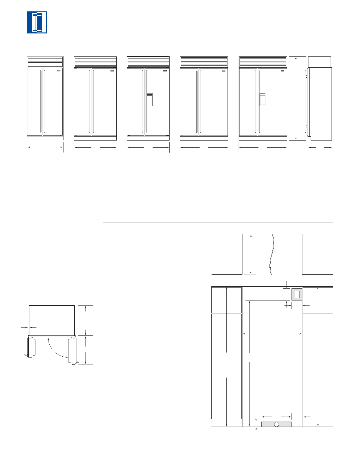
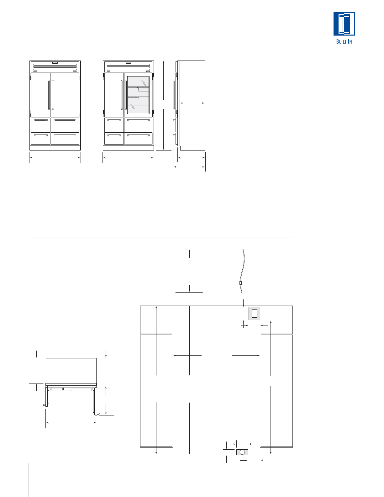
OVERALL DIMENSIONS
Side-by-Side Models
84"
(2134)
36"
(914)
Model 661
Width 36" (914)
Height 84" (2138)
Depth 24" (610)
SIDE-BY-SIDE
Model 661
Model 642
Model 685
Ice | Water Dispensing
Model 632
Model 695
Ice | Water Dispensing
3
/8"(10)
FRAME
EXTENSION
90˚
INSTALLATION
Refer to the
installation instructions shipped with
each Sub-Zero
product for detailed
specifications.
16
42"
(1067)
Model 642
Width 42" (1067)
Height 84" (2138)
Depth 24" (610)
INSTALLATION SPECIFICATIONS
Side-by-Side Models
Model 661
A) Rough Opening Width 35
B) Min Door Clearance 20
Model 642
A) Rough Opening Width 41
B) Min Door Clearance 25
Model 685
7
23
(606)
BEHIND
FRAME
A) Rough Opening Width 41
/8"
B) Min Door Clearance 25
Model 632
A) Rough Opening Width 47
B
B) Min Door Clearance 29
Model 695
A) Rough Opening Width 47
B) Min Door Clearance 29
Dimensions are for finished rough openings.
Door swing clearances are based on
stainless steel door and handle dimensions.
42"
(1067)
Model 685
Ice | Water Dispensing
Width 42" (1067)
Height 84" (2138)
Depth 24" (610)
1
/2" (902)
3
1
/2" (1054)
5
1
/2" (1054)
5
1
/2" (1207)
1
/4" (743)
1
/2" (1207)
1
/4" (743)
48"
(1219)
Model 632
Width 48" (1219)
Height 84" (2138)
Depth 24" (610)
/4" (527)
/16" (649)
/16" (649)
83" (2108)
MIN HEIGHT
REQUIRED TO
FINISHED
FLOORING
(LEVELERS IN)
48"
(1219)
24"
(610)
Model 695
Ice | Water Dispensing
Width 48" (1219)
Height 84" (2138)
Depth 24" (610)
Illustrations shown in stainless steel design.
24"
(610)
ROUGH
OPENING
DEPTH
TOP VIEW
LOCATE ELECTRICAL
WITHIN SHADED AREA
ROUGH OPENING WIDTH
751/2"
(1918)
LOCATE WATER SUPPLY
WITHIN SHADED AREA
3"
(76)
EXTEND
WATER LINE
APPROX 36" (914)
FROM BACK WALL
SHUT-OFF
VALV E
7"
(178)
A
18"
(457)
E
6"
(152)
6"
(152)
833/4" (2127)
ROUGH OPENING
HEIGHT TO
FINISHED
FLOORING WITH
STANDARD
11" (279) GRILLE
W
FRONT VIEW
Page 17
OVERALL DIMENSIONS
Models 648PRO and 648PROG
84"
(2134)
237/8"
(606)
SIDE-BY-SIDE
Free-Standing or
Built-In
Model 648PRO
Model 648PROG
with Glass Door
48"
(1219)
Model 648PRO
48"
(1219)
Model 648PROG
257/8"
(657)
305/32"
(766)
with Glass Door
Width 48" (1219)
Height 84" (2134)
Depth 23
7
/8" (606)*
7
/8" (657)**
25
Width 48" (1219)
Height 84" (2134)
Depth 23
7
/8" (606)*
7
/8" (657)**
25
*Depth from behind face frame to back of unit for standard installation.
**Depth from front of face frame to back of unit for flush installation.
INSTALLATION SPECIFICATIONS
Models 648PRO and 648PROG
Free-Standing or Built-In
Models 648PRO and 648PROG can be
used free-standing or installed as a standard
ROUGH
OPENING DEPTH
24" (610)
STANDARD
26" (660)
FLUSH
or flush built-in application. For standard
built-in installations, the face frame of the
unit will extend 2" (51) beyond cabinetry.
In flush built-in installations, the front of the
face frame will be flush with surrounding
cabinetry.
Dimensions are for finished rough openings.
MIN 48" (1219)
1/4" COPPER
WATER LINE
SHUT-OFF
VALV E
TOP VIEW
LOCATE ELECTRICAL
WITHIN SHADED AREA
7"
(178)
E
6"
(152)
INSTALLATION
Refer to the
installation instructions shipped with
each Sub-Zero
product for detailed
specifications.
237/8"
(606)
BEHIND
FAC E
FRAME
48"
(1219)
257/8"
(657)
TO FRONT
OF FACE
FRAME
283/4"
(730)
Dimensions in parentheses are in
millimeters unless otherwise specified.
831/2" (2121)
MIN HEIGHT
REQUIRED TO
FINISHED
FLOORING
(LEVELERS IN)
471/2" (1206) STANDARD
833/4" (2127)
ROUGH
OPENING
HEIGHT TO
FINISHED
FLOORING
ROUGH
OPENING WIDTH
48" (1219) FLUSH
LOCATE WATER SUPPLY
WITHIN SHADED AREA
3" (76)
FRONT VIEW
6"
(152)
W
53/16"
(132)
751/2"
(1918)
17
Page 18
PANEL WEIGHT
The weight of
each door panel
cannot exceed 50
lbs (23 kg).
ANTI-TIP BLOCKING KIT
To prevent the unit from tipping forward and to
provide a stable installation, the unit must be
secured in place with an anti-tip blocking kit. If
there is a solid soffit above the unit with clearance between the unit and the soffit of 1" (25)
or less, you won‘t need to block the unit. But for
installations with clearances of more than 1"
(25), you must block the unit with the anti-tip
blocking kit (wood block and hardware) provided
with each Sub-Zero Built-In model. Refer to the
Built-In Installation Guide packed with the appliance, which provides step-by-step procedures
for making sure the unit is installed properly.
INTEGRATING CABINETRY
In your plan for panels, be sure you are working
with the Sub-Zero panel design family called for
in your design. If you have chosen the stainless
steel design, the unit will be shipped complete
with wrapped stainless steel doors and handle
hardware. You will not have to install door
panels.
Specifications on the following pages provide
panel dimensions and installation considerations
for framed and overlay door panels.
Side panels can be used with the framed,
overlay and stainless steel design applications.
Refer to specifications on page 24.
FRAMED DOOR PANELS
If you and your client have ordered a framed
design model, you will be adding panels to give
the unit the custom Sub-Zero look. For exact
door panel dimensions for Built-In framed
models, refer to the Framed Panel Specifications
on pages 20–21. Also refer to the full-scale illustrations at the end of this section for panel and
handle considerations.
The traditional framed models come with an
elegant, smooth, full-length handle. Optional
extended full-length handles that provide additional finger clearance for raised panels are available through your Sub-Zero dealer.
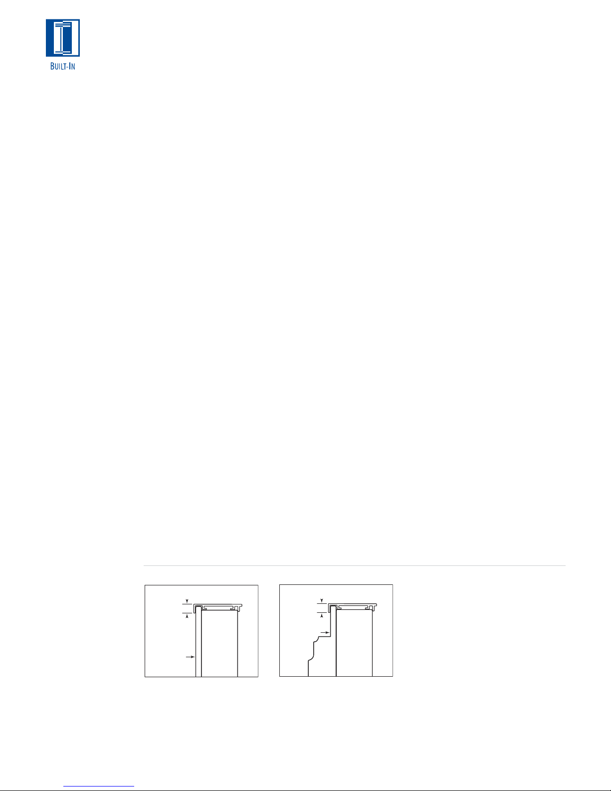
If the thickness of the custom panels is less
than 1/4" (6), they must be backed up with a
sheet of shim material to build the total thickness to 1/4" (6). If the panel is thicker than 1/4"
(6), an edge must be routed around the panel to
ensure a proper fit. Refer to illustrations 1 and 2.
IMPORTANT NOTE: On all framed models,
routing, recessing or optional extended handles
may be required on raised panels for finger clearance under the handle. Refer to the full-scale
illustrations at the end of this section.
For glass door Models 601RG, 611G and 650G,
the refrigerator door panel must include a cutout to accommodate the window. Refer to the
Framed Panel Specifications on pages 20–21.
IMPORTANT NOTE: On glass door models, the
glass portion of the door must be exposed and
not covered by any part of the panel.
For Models 685 and 695, the refrigerator door
panel must include a cut-out to accommodate
the glasswell and bezel. The thickness of the
panel in this area can range from 1/4" (6) to a
maximum of 11/8" (29). If the panel is thicker,
provisions must be made to rout out a space to
accommodate the decorative bezel surrounding
the glasswell.
1
PANELS
/4" (6) THICK OR LESS
Trim reveal
1
/4" (6) min
1
/4" (6) Panel
18
PANELS THICKER THAN
Trim reveal
1
/4" (6) min
Rout to 1/4" (6)
thickness
Illus. 2Illus. 1
1
/4" (6)
Page 19

GLASSWELL PANEL OPTIONS
If you choose not to use custom wood panels
above or below the glasswell for Model 685 or
695 framed application, a stainless steel insert
panel will be provided with the partial framed
accessory kit. This accessory kit (FRAMPAR),
includes partial framed molding and classic
stainless steel inset handle panel to provide a
spill-resistant finish above and below the glasswell on the refrigerator door only. Refer to the
Framed Panel Specifications for this option on
page 21.
With the framed retrofit accessory kit, existing
Model 680 or 690 door panels can be used on a
new Model 685 or 695 framed unit. This accessory kit (FRAMRET) includes framed retrofit
moldings and classic stainless steel inset handle
panels to accommodate existing Model 680 or
690 framed refrigerator and freezer door panels.
Both accessory kits are available through your
Sub-Zero dealer. See illustrations below.
OPTIONAL PANEL GRILLE
An 11" (279) louvered grille is standard on
framed applications. Optional louvered grilles are
available in 1" (25) height increments from 10"
(254) to 15" (381) for all Built-In models except
Models 601R, 601RG, 601F, 648PRO and
648PROG.
You may choose to use Sub-Zero‘s optional
panel grille for some of your framed applications.
The panel grilles can be used with all Built-In
models except Models 601R, 601RG, 601F,
648PRO and 648PROG and are available in 1"
(25) height increments from 10" (254) to 15"
(381).
For each model, the width of the panel grille will
be the same, regardless of the height you have
chosen. To determine the panel grille insert size,
use the width dimension listed for your model
and the height dimension for the grille option
you have chosen. Specifications for the Panel
Grille Option are listed on page 21.
INSTALLATION
To install framed
panels, see the
detailed procedures
outlined in the
Sub-Zero Built-In
Installation Guide.
Partial Framed Kit
FRAMPAR
Dimensions in parentheses are in
millimeters unless otherwise specified.
Framed Retrofit Kit
FRAMRET
19
Page 20

C
C C
H
W
H
A
B
D
14"
(356)
H
W
H
A
B
14"(356)
FRAMED DOOR PANEL SPECIFICATIONS
All Refrigerator | All Freezer Framed (F) Models
FRAMED DOOR PANEL SPECIFICATIONS
Over-and-Under Framed (F) Models
Model 601R W H
Refrigerator Framed Panel 34
1
/8" (867) 5815/16" (1497)
Raised Panel Handle Recess Location –
Refrigerator Panel A) 29
15
/32" (749)
Model 601RG W H
Refrigerator Framed Panel 34
1
/8" (867) 5815/16" (1497)
Raised Panel Handle Recess Location –
Refrigerator Panel A) 29
Window Cut-out Dimensions 25
Window Cut-out Location C) 4
15
/32" (749)
3
/8" (645) 413/16" (1046)
3
/8" (111) D) 133/8" (340)
Model 601F W H
Freezer Framed Panel 34
1
/8" (867) 5815/16" (1497)
Raised Panel Handle Recess Location –
Freezer Panel A) 29
15
/32" (749)
IMPORTANT NOTE: Panel specifications are for Built-In framed (F)
models. Panel specifications for overlay models are on pages 25–26.
Model 611 W H
Refrigerator Framed Panel 28
Freezer Framed Panel 28
1
/8" (714) 481/16" (1221)
1
/8" (714) 183/8" (467)
Raised Panel Handle Recess Location –
Refrigerator Panel A) 24
Freezer Panel B) 14
1
/32" (610)
1
/16" (357)
Model 611G W H
Refrigerator Framed Panel 28
Freezer Framed Panel 28
1
/8" (714) 481/16" (1221)
1
/8" (714) 183/8" (467)
Raised Panel Handle Recess Location –
Refrigerator Panel A) 24
Freezer Panel B) 14
Window Cut-out Dimensions 19
Window Cut-out Location C) 4
1
/32" (610)
1
/16" (357)
3
/8" (492) 395/16" (999)
3
/8" (111) D) 43/8" (111)
Model 650 W H
Refrigerator Framed Panel 34
Freezer Framed Panel 34
1
/8" (867) 481/16" (1221)
1
/8" (867) 183/8" (467)
Raised Panel Handle Recess Location –
Refrigerator Panel A) 24
Freezer Panel B) 17
1
/32" (610)
1
/16" (433)
Model 611G W H
1
Refrigerator Framed Panel 34
Freezer Framed Panel 34
/8" (867) 481/16" (1221)
1
/8" (867) 183/8" (467)
Raised Panel Handle Recess Location –
Refrigerator Panel A) 24
Freezer Panel B) 17
Window Cut-out Dimensions 25
Window Cut-out Location C) 4
1
/32" (610)
1
/16" (433)
3
/8" (645) 395/16" (999)
3
/8" (111) D) 43/8" (111)
FRAMED PANELS
Panel specifications
are for Built-In
framed (F) models.
To install framed
panels, see the
detailed procedures
14"(356)
A
outlined in the
Sub-Zero Built-In
Installation Guide.
20
W
Models 601R
and 601F
IMPORTANT NOTE: Panel specifications are for Built-In framed (F)
models. Panel specifications for overlay models are on pages 25–26.
C
C C
H
14"(356)
A
D
W
H
Model 601RG
Models 611 and 650 Models 611G and 650G
Page 21
FRAMED DOOR PANEL SPECIFICATIONS
Side-by-Side Framed (F) Models
PARTIAL FRAMED DOOR PANEL OPTION
Ice | Water Dispensing Framed (F) Models
Model 661 W H
Refrigerator Framed Panel 19
Freezer Framed Panel 14
1
/8" (486) 6711/16" (1719)
5
/8" (371) 6711/16" (1719)
Raised Panel Handle Recess Location –
Refrigerator | Freezer Panel A) 38
5
/32" (969)
Model 642 W H
Refrigerator Framed Panel 24" (610) 67
Freezer Framed Panel 15
5
/8" (397) 6711/16" (1719)
11
/16" (1719)
Raised Panel Handle Recess Location –
Refrigerator | Freezer Panel A) 38
5
/32" (969)
Model 685 W H
11
Refrigerator Framed Panel 24" (610) 67
Freezer Framed Panel 15
5
/8" (397) 6711/16" (1719)
/16" (1719)
Raised Panel Handle Recess Location –
Refrigerator | Freezer Panel A) 38
Glasswell Cut-out Dimensions 5
Glasswell Location (Refrigerator) E) 1
5
/32" (969)
7
/8" (150) 127/16" (315)
9
/16" (39) F) 289/16" (726)
Model 632 W H
Refrigerator Framed Panel 27
Freezer Framed Panel 17
11
/16" (703) 6711/16" (1719)
15
/16" (456) 6711/16" (1719)
Raised Panel Handle Recess Location –
Refrigerator | Freezer Panel A) 38
5
/32" (969)
Model 695 W H
11
Refrigerator Framed Panel 27
Freezer Framed Panel 17
/16" (703) 6711/16" (1719)
15
/16" (456) 6711/16" (1719)
Raised Panel Handle Recess Location –
Refrigerator | Freezer Panel A) 38
Glasswell Cut-out Dimensions 5
Glasswell Location (Refrigerator) E) 1
5
/32" (969)
7
/8" (150) 127/16" (315)
9
/16" (39) F) 289/16" (726)
IMPORTANT NOTE: Panel specifications are for Built-In framed (F)
models. Panel specifications for overlay models are on pages 25–26.
For Models 685 and 695, panel thickness in the glasswell area can
range from
you must rout out a minimum
1
/4" (6) to a maximum of 11/8" (29). If the panel is thicker,
1
/4" (6) flat landing area to accommo-
date the bezel surrounding the glasswell.
Model 685 W H
Refrigerator Partial Framed Panel 15
Freezer Partial Framed Panel 15
5
/8" (397) 6711/16" (1719)
5
/8" (397) 6711/16" (1719)
Model 695 W H
Refrigerator Partial Framed Panel 17
Freezer Partial Framed Panel 17
15
/16" (456) 6711/16" (1719)
15
/16" (456) 6711/16" (1719)
The partial framed accessory kit (FRAMPAR) is required for this option.
Kit includes partial framed molding and classic stainless steel inset
handle panels for above and below glasswell on the refrigerator door.
PANEL GRILLE OPTION
Framed (F) Models
Models 611 and 611G W
Grille Panel Width 28
3
/16" (716)
Models 650, 650G, 661 W
Grille Panel Width 34
3
/16" (868)
Models 642 and 685 W
Grille Panel Width 40
3
/16" (1021)
Models 632 and 695 W
Grille Panel Width 46
3
/16" (1173)
10" (254) Grille H
Grille Panel Height 8
11" (279) Grille
(standard) H
Grille Panel Height 9
15
/16" (227)
15
/16" (252)
12" (305) Grille Height H
Grille Panel Height 10
15
/16" (278)
13" (330) Grille H
Grille Panel Height 11
15
/16" (303)
14" (356) Grille H
Grille Panel Height 12
15
/16" (329)
15" (381) Grille H
Grille Panel Height 13
15
/16" (354)
For panel grille insert size, use width dimension listed
for your model and height dimension for grille option.
11" (279) grille is standard.
14" (356)
A
Models 661, 642
H
WW
Models 685 and 695 Models 685 and 695
and 632
E
H
F
WW WW
Partial Framed Option
FRAMED PANELS
Panel specifications
are for Built-In
H
framed (F) models.
To install framed
panels, see the
detailed procedures
outlined in the
Sub-Zero Built-In
Installation Guide.
Dimensions in parentheses are in
millimeters unless otherwise specified.
21
Page 22
PANEL WEIGHT
The weight of each
door panel assembly
cannot exceed
50 lbs (23 kg).
PANEL
THICKNESS
The total thickness
of all panels for an
overlay model must
be a minimum of
5
/8" (16) thick.
OVERLAY DOOR PANELS
If you and your client have ordered an overlay
design model, you will be adding panels to give
the unit the custom Sub-Zero look. The overlay
panel design option is available on all Built-In
units except Models 648PRO and 648PROG.
For exact door panel dimensions for Built-In
overlay models, refer to the Overlay Panel Specifications on pages 25–26.
The overlay design allows decorative panels to
cover the door trim for a more seamless
appearance that blends with the design of the
room. To achieve this look, the most common
way is to work with three panels—the decorative
overlay panel, a 0.10" (3) spacer panel and a 1/4"
(6) backer panel. Depending on your cabinet
IMPORTANT NOTE: Keep in mind that the
Sub-Zero door panels have the potential for
hitting adjacent cabinets and/ or countertops
when they are opened. You need to be aware of
your surrounding cabinetry and space limitations
when using the overlay models. Refer to the fullscale illustrations at the end of this section.
For glass door Models 601RG, 611G and 650G,
the refrigerator door panel must include a cutout to accommodate the window. Refer to the
Overlay Panel Specifications for Models 601RG,
611G and 650G on page 25.
IMPORTANT NOTE: On glass door models, the
glass portion of the door must be exposed and
not covered by any part of the panel.
manufacturer, this could be one panel routed for
different dimensions or, more likely, three different panels.
Regardless of the physical construction of the
panels (routing or three-panel assembly), you will
need to follow the Overlay Panel Specifications
on the following pages for exact sizing and panel
placement to ensure a proper fit.
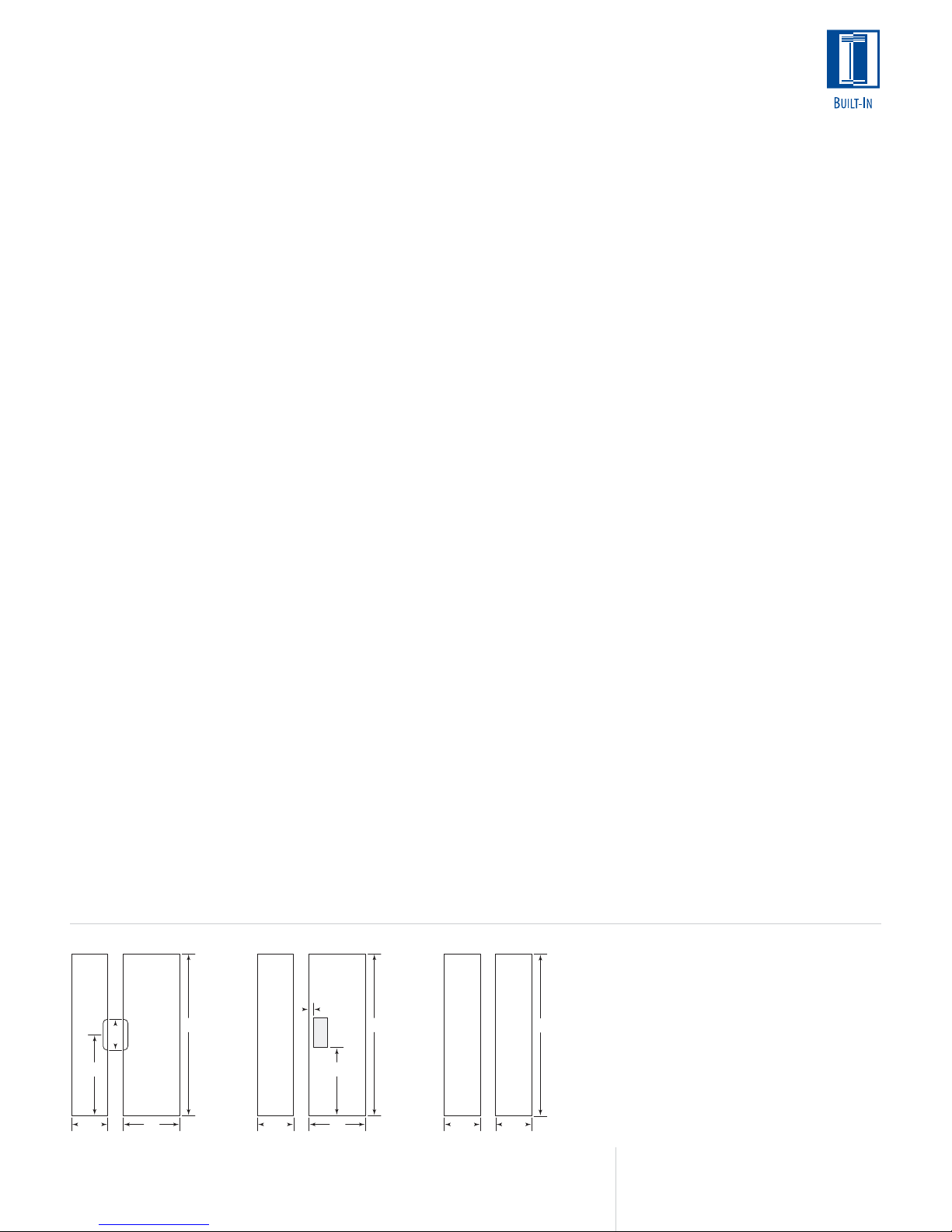
Illustration 3 is a cross section view of the threepanel assembly showing placement of the door,
drawer or grille trim. Illustration 4 shows a rear
view of the three-panel assembly and critical
dimensions, standard for all models.
INSTALLATION
To install overlay
panels, see the
detailed procedures
outlined in the
Sub-Zero Built-In
Installation Guide.
22
Spacer Panel
.10"
(3)
5
1
Overlay Panel
1
/4"
(6)
5
/16"
/32"
(4)
/16"
(2)
Backer Panel
(8)
min
Door/Drawer/
Grille Trim
Overlay Panel
~3/4"
(19)
Illus. 4Illus. 3
.10"
Spacer Panel
1
/4"
(3)
(6)
Backer
Panel
Page 23
OVERLAY DOOR PANELS
Spacer Panel
Overlay Panel
1
/4"
(6)
Backer
Panel
.10"
(3)
~3/4"
(19)
If you are using an overlay door panel with
Model 601R, 601RG, 601F, 611, 611G, 650 or
650G, it is necessary to rout a space for the
unit‘s lower hinge plate so it does not strike the
door panel. Refer to illustration 5.
For Models 611, 611G, 650 and 650G, you will
minimize the reveal between the bottom of the
overlay door panel and the top of the overlay
drawer panel. Refer to illustration 6.
IMPORTANT NOTE: If you choose not to rout a
space for the lower hinge plate, you can reduce
the total height of the overlay panel (decorative
panel only) by 1/2" (13).
For Models 685 and 695, the refrigerator door
panel must include a cut-out to accommodate
the glasswell and bezel. The thickness of the
panel in this area can range from 1/4" (6) to a
maximum of 11/8" (29). If the panel is thicker,
provisions must be made to rout out a space to
accommodate the decorative bezel surrounding
the glasswell. Refer to the Overlay Panel Specifications for Models 685 and 695 on page 26.
OVERLAY PANEL GRILLE
Overlay grille panels for the panel grille match
the design of the door panels. Overlay units,
except Models 601R, 601RG and 601F, come
standard with an 11" (279) panel grille. Optional
grilles are available in 1" (25) height increments
from 10" (254) to 15" (381). Overlay grille panel
specifications for the panel grille are listed on
page 26. Also refer to illustration 7 below for
additional overlay panel dimensions.
Do not exceed the panel dimensions listed
for the appropriate overlay grille panel you
are specifying. The decorative panel cannot
be any larger or it may restrict the airflow
to the compressor area and cause problems
with the operation of the Sub-Zero unit.
PANEL WEIGHT
The weight of each
door panel assembly
cannot exceed
50 lbs (23 kg).
PANEL
THICKNESS
The total thickness
of all panels for an
overlay model must
be a minimum of
5
/8" (16) thick.
Do not exceed the overlay decorative panel
dimensions for Models 611, 611G, 650 or
650G listed on page 25. If you try to make
the reveal tighter between the door and
drawer panels, the panels may hit when
opening and closing, causing possible
damage to the panels and the Sub-Zero unit.
Overlay Panel
27
"
/32
(21)
1
/2
(13)
3
/8"(10)
"
Overlay Panel
1
/4
"(6) Backer Panel
Spacer Panel
3"
Bottom Edge –
Hinge Side
(rear view)
(76)
Spacer Panel
Backer
Panel
5
(8)
17
/32
(13)
/16
"
"
Illus. 5 Illus. 6
Dimensions in parentheses are in
millimeters unless otherwise specified.
Illus. 7
23
Page 24

INSTALLATION
To install overlay
panels, see the
detailed procedures
outlined in the
Sub-Zero Built-In
Installation Guide.
HANDLE HARDWARE
Overlay models come without handle hardware.
The beauty of this design is that you can match
the surrounding cabinet hardware. You or the
cabinet manufacturer must provide handle
hardware to match the overall decorating
scheme.
The handle hardware must be installed before
installing the panel assembly. Use larger D-style
handles. If screws with thick heads are used,
the screws will need to be countersunk into the
door before the panel is put into place.
IMPORTANT NOTE: Sub-Zero does not recommend using single pull knobs on any of its BuiltIn models.
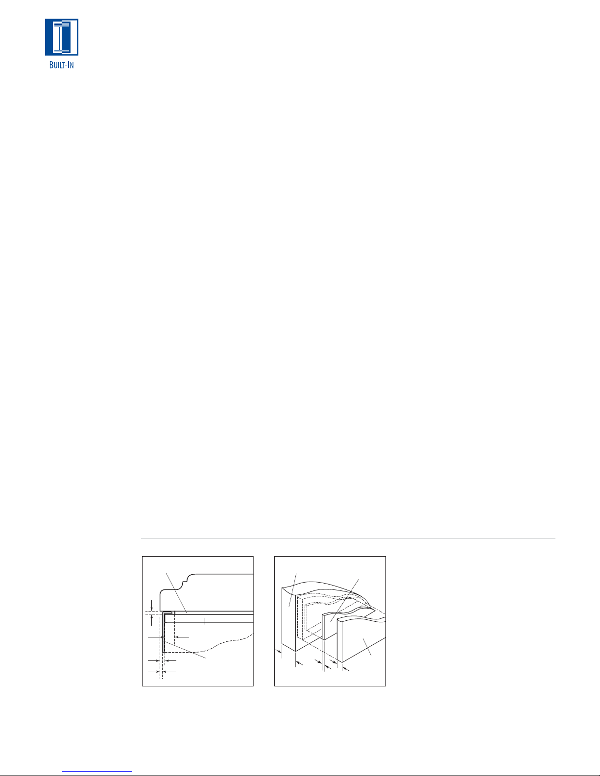
For overlay Models 685 and 695, mounting
placement of the refrigerator door handle must
assure proper access to the glasswell and
adequate clearance under the handle. Illustration
8 shows placement of the refrigerator door
handle in relationship to the glasswell bezel on
stainless steel models.
Optional stainless steel handles are available in a
variety of diameters and lengths, as are handles
to match the color and style of Wolf ovens.
Contact your Sub-Zero dealer for specifics.
Refer to the full-scale illustrations at the end of
this section for handle hardware considerations.
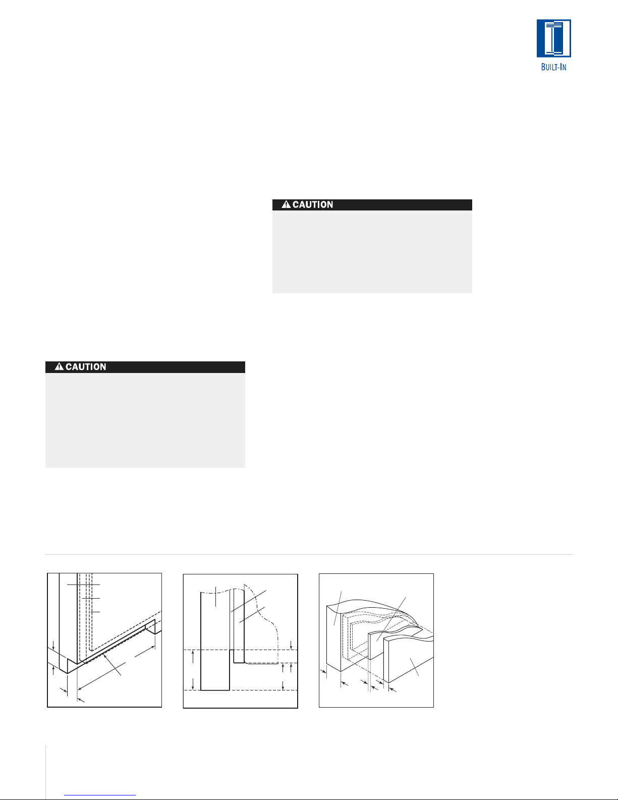
SIDE PANELS
Side panels can be used with the framed,
overlay and stainless steel design applications.
When planning for side panels with the installa-
tion of a Built-In model, you need to be aware of
space configuration to achieve a pleasing fit.
Depending on the exact panel you are using with
your unit, the height of the panel will vary.
Cut-outs around the kickplate and grille area are
required if a 1/4" (6) thick panel will be inserted
into the main frame channel. The panel will need
to be 24" (610) deep. Refer to illustration 9 for
placement of cut-outs. If a 3/8" (10) thick panel is
used, the panel will abut the main frame and
should be 23
7
/8" (606) deep. The toe kick area
may or may not be cut out depending on the
look you want to achieve. These dimensions do
not apply to Models 648PRO and 648PROG.
1"
(25)
Illus. 8
24
(51)
SERVICE INFORMATION
131/4" (337)
1
/4" (6)
237/8"
Glasswell
Profile
2"
Handle
Profile
3" (76)
Illus. 9
(606)
1
/4" (6)
3" (76)
4" (102)
Sub-Zero Freezer Co., Inc.
Customer Service Department
P. O. Box 44130
Madison, WI 53744-4130
Service line: 800-222-7820
E-mail: customerservice@subzero.com
Website: www.subzero.com
If service is necessary, contact customer
service by phone or e-mail and include
the model and serial number.
Make sure that product registration
forms are filled out and returned, to
assure that your information is in our
database.
Dimensions in parentheses are in
millimeters unless otherwise specified.
Page 25

OVERLAY DOOR PANEL SPECIFICATIONS
All Refrigerator | All Freezer Overlay (O) Models
OVERLAY DOOR PANEL SPECIFICATIONS
Over-and-Under Overlay (O) Models
Model 601R W H
Refrigerator Overlay Panel 34
Refrigerator Spacer Panel 33
Refrigerator Backer Panel 34
7
/16" (875) 591/4" (1505)
1
/2" (851) 585/16" (1481)
1
/8" (867) 5815/16" (1497)
Model 601RG W H
Refrigerator Overlay Panel 34
Refrigerator Spacer Panel 33
Refrigerator Backer Panel 34
Window Cut-out Dimensions 25
Window Cut-out Location C) 4
7
/16" (875) 591/4" (1505)
1
/2" (851) 585/16" (1481)
1
/8" (867) 5815/16" (1497)
7
/16" (646) 411/4" (1048)
1
/2" (114) D) 131/2" (343)
Model 601F W H
Freezer Overlay Panel 34
Freezer Spacer Panel 33
Freezer Backer Panel 34
7
/16" (875) 591/4" (1505)
1
/2" (851) 585/16" (1481)
1
/8" (867) 5815/16" (1497)
IMPORTANT NOTE: Panel specifications are for Built-In overlay (O)
models. Panel specifications for framed models are on pages 20–21.
Model 611 W H
Refrigerator Overlay Panel 28
Refrigerator Spacer Panel 27
Refrigerator Backer Panel 28
Freezer Overlay Panel 28
Freezer Spacer Panel 27
Freezer Backer Panel 28
7
/16" (722) 487/8" (1241)
1
/2" (699) 477/16" (1205)
1
/8" (714) 481/16" (1221)
7
/16" (722) 1811/16" (475)
1
/2" (699) 173/4" (451)
1
/8" (714) 183/8" (467)
Model 611G W H
Refrigerator Overlay Panel 28
Refrigerator Spacer Panel 27
Refrigerator Backer Panel 28
Freezer Overlay Panel 28
Freezer Spacer Panel 27
Freezer Backer Panel 28
Window Cut-out Dimensions 19
Window Cut-out Location C) 4
7
/16" (722) 487/8" (1241)
1
/2" (699) 477/16" (1205)
1
/8" (714) 481/16" (1221)
7
/16" (722) 1811/16" (475)
1
/2" (699) 173/4" (451)
1
/8" (714) 183/8" (467)
7
/16" (494) 393/8" (1000)
1
/2" (114) D) 5" (127)
Model 650 W H
Refrigerator Overlay Panel 34
Refrigerator Spacer Panel 33
Refrigerator Backer Panel 34
Freezer Overlay Panel 34
Freezer Spacer Panel 33
Freezer Backer Panel 34
7
/16" (875) 487/8" (1241)
1
/2" (851) 477/16" (1205)
1
/8" (867) 481/16" (1221)
7
/16" (875) 1811/16" (475)
1
/2" (851) 173/4" (451)
1
/8" (867) 183/8" (467)
W
and 601F
H
C
C C
D
W
Model 601RGModels 601R
C C
H
H
H
W
Models 611 and 650 Models 611G and
650G
Model 650G W H
Refrigerator Overlay Panel 34
Refrigerator Spacer Panel 33
Refrigerator Backer Panel 34
Freezer Overlay Panel 34
Freezer Spacer Panel 33
Freezer Backer Panel 34
Window Cut-out Dimensions 25
Window Cut-out Location C) 4
7
/16" (875) 487/8" (1241)
1
/2" (851) 477/16" (1205)
1
/8" (867) 481/16" (1221)
7
/16" (875) 1811/16" (475)
1
/2" (851) 173/4" (451)
1
/8" (867) 183/8" (467)
7
/16" (646) 393/8" (1000)
1
/2" (114) D) 5" (127)
IMPORTANT NOTE: Panel specifications are for Built-In overlay (O)
models. Panel specifications for framed models are on pages 20–21.
C
OVERLAY PANELS
Panel specifications
H
are for Built-In
overlay (O) models.
To install overlay
D
panels, see the
detailed procedures
outlined in the
H
W
Sub-Zero Built-In
Installation Guide.
Dimensions in parentheses are in
millimeters unless otherwise specified.
25
Page 26

OVERLAY PANELS
Panel specifications
are for Built-In
overlay (O) models.
To install overlay
panels, see the
detailed procedures
outlined in the
Sub-Zero Built-In
Installation Guide.
H
WW
Models 661, 642
and 632
E
H
F
WW
Models 685 and 695
26
OVERLAY DOOR PANEL SPECIFICATIONS
Side-by-Side Overlay (O) Models
Model 661 W H
Refrigerator Overlay Panel 19
Refrigerator Spacer Panel 18
Refrigerator Backer Panel 19
Freezer Overlay Panel 14
Freezer Spacer Panel 14" (356) 67
Freezer Backer Panel 14
7
/16" (494) 68" (1727)
1
/2" (470) 671/16" (1703)
1
/8" (486) 6711/16" (1719)
15
/16" (379) 68" (1727)
5
/8" (371) 6711/16" (1719)
1
/16" (1703)
Model 642 W H
Refrigerator Overlay Panel 24
Refrigerator Spacer Panel 23
Refrigerator Backer Panel 24" (610) 67
Freezer Overlay Panel 15
Freezer Spacer Panel 15" (381) 67
Freezer Backer Panel 15
5
/16" (618) 68" (1727)
3
/8" (594) 671/16" (1703)
15
/16" (405) 68" (1727)
5
/8" (397) 6711/16" (1719)
11
/16" (1719)
1
/16" (1703)
Model 685 W H
Refrigerator Overlay Panel 24
Refrigerator Spacer Panel 23
Refrigerator Backer Panel 24" (610) 67
Freezer Overlay Panel 15
Freezer Spacer Panel 15" (381) 67
Freezer Backer Panel 15
Glasswell Cut-out Dimensions 5
Glasswell Location (Overlay) E) 1
Glasswell Location (Spacer) E) 1
Glasswell Location (Backer) E) 1
5
/16" (618) 68" (1727)
3
/8" (594) 671/16" (1703)
15
/16" (405) 68" (1727)
5
/8" (397) 6711/16" (1719)
7
/8" (150) 127/16" (315)
11
/16" (43) F) 283/4" (730)
1
/4" (31) F) 281/4" (718)
9
/16" (39) F) 289/16" (726)
11
/16" (1719)
1
/16" (1703)
Model 632 W H
Refrigerator Overlay Panel 28" (711) 68" (1727)
Refrigerator Spacer Panel 27
Refrigerator Backer Panel 27
Freezer Overlay Panel 18
Freezer Spacer Panel 17
Freezer Backer Panel 17
1
/16" (687) 671/16" (1703)
11
/16" (703) 6711/16" (1719)
1
/4" (464) 68" (1727)
5
/16" (440) 671/16" (1703)
15
/16" (456) 6711/16" (1719)
Model 695 W H
Refrigerator Overlay Panel 28" (711) 68" (1727)
Refrigerator Spacer Panel 27
Refrigerator Backer Panel 27
Freezer Overlay Panel 18
Freezer Spacer Panel 17
Freezer Backer Panel 17
Glasswell Cut-out Dimensions 5
Glasswell Location (Overlay) E) 1
Glasswell Location (Spacer) E) 1
Glasswell Location (Backer) E) 1
1
/16" (687) 671/16" (1703)
11
/16" (703) 6711/16" (1719)
1
/4" (464) 68" (1727)
5
/16" (440) 671/16" (1703)
15
/16" (456) 6711/16" (1719)
7
/8" (150) 127/16" (315)
11
/16" (43) F) 283/4" (730)
1
/4" (31) F) 281/4" (718)
9
/16" (39) F) 289/16" (726)
IMPORTANT NOTE: Panel specifications are for Built-In overlay (O)
models. Panel specifications for framed models are on pages 20–21.
For Models 685 and 695, panel thickness in the glasswell area can
range from
you must rout out a minimum
1
/4" (6) to a maximum of 11/8" (29). If the panel is thicker,
1
/4" (6) flat landing area to accommo-
date the bezel surrounding the glasswell.
OVERLAY GRILLE PANEL
Overlay (O) Models
Width Dimensions
Models 611 and 611G W
Overlay Panel Width 28
Spacer Panel Width 27
Backer Panel Width 28
7
/16" (722)
1
/2" (699)
1
/8" (714)
Models 650, 650G, 661 W
Overlay Panel Width 34
Spacer Panel Width 33
Backer Panel Width 34
7
/16" (875)
1
/2" (851)
1
/8" (867)
Models 642 and 685 W
7
Overlay Panel Width 40
Spacer Panel Width 39
Backer Panel Width 40
/16" (1027)
1
/2" (1003)
1
/8" (1019)
Models 632 and 695 W
Overlay Panel Width 46
Spacer Panel Width 45
Backer Panel Width 46
7
/16" (1180)
1
/2" (1156)
1
/8" (1172)
Height Dimensions
10" (254) Grille H
Overlay Panel Height 9
Spacer Panel Height 8
Backer Panel Height 8
11" (279) Grille
(standard) H
Overlay Panel Height 10
Spacer Panel Height 9
Backer Panel Height 9
1
/4" (235)
5
/16" (211)
15
/16" (227)
1
/4" (260)
5
/16" (237)
15
/16" (252)
12" (305) Grille Height H
Overlay Panel Height 11
Spacer Panel Height 10
Backer Panel Height 10
1
/4" (286)
5
/16" (262)
15
/16" (278)
13" (330) Grille H
Overlay Panel Height 12
Spacer Panel Height 11
Backer Panel Height 11
1
/4" (311)
5
/16" (287)
15
/16" (303)
14" (356) Grille H
Overlay Panel Height 13
Spacer Panel Height 12
Backer Panel Height 12
1
/4" (337)
5
/16" (313)
15
/16" (329)
15" (381) Grille H
Overlay Panel Height 14
Spacer Panel Height 13
Backer Panel Height 13
1
/4" (362)
5
/16" (338)
15
/16" (354)
For grille panel size, use width dimensions
listed for your model and height dimensions
for grille option. 11" (279) grille is standard.
Panel grille is available for all overlay units
except Models 601R, 601RG and 601F.
Page 27

PANEL AND HANDLE PROFILE – FRAMED APPLICATION
OPTIONAL
EXTENDED
FULL-LENGTH
HANDLE
STANDARD
FULL-LENGTH
HANDLE
1"
(25)
2"
(51)
1
/4"(6) FRAMED PANEL
3"
(76)
11/4"(32) PANEL
1"(25) PANEL
3
/4"(19) PANEL
1
/2"(13) PANEL
1
/4"(6) PANEL
FULL-SCALE
TEMPLATES
The full-scale
illustrations on the
following pages
enable you to understand some of the
unique situations
you may face as you
plan for the installation of the Built-In
models. Use these
illustrations as
templates for
panel and handle
hardware
considerations.
The full-scale illustration above shows
handle placement for the framed application standard full-length handle and
the optional extended full-length handle
shown in the dashed line.
DOOR
Dimensions in parentheses are in
millimeters unless otherwise specified.
27
Page 28

PANEL AND HANDLE PROFILE – OVERLAY AND STAINLESS STEEL APPLICATION
STANDARD STAINLESS STEEL HANDLE
1"
2"
(51)
3"
(76)
11/4" (32) PANEL
1" (25) PANEL
3
/4" (19) PANEL
5
/8" (16) PANEL
1
/2" (13) PANEL
1
/4" (6) PANEL
1
/4" (6) APPROXIMATE THICKNESS OF WRAPPED STAINLESS STEEL DOOR
DOOR
NOTE: FOR OVERLAY APPLICATIONS, OPTIONAL STAINLESS STEEL HANDLE
MUST BE MOUNTED ON PANEL MINIMUM 5/8" (16) THICK.
The full-scale illustration above shows
handle placement for the standard
stainless steel handle on the wrapped
stainless steel door and on overlay
panel applications shown in the dashed
line.
IMPORTANT NOTE: For overlay applications, the panel must be a minimum of
5
/8" (16) thick to support mounting the
handle hardware.
For overlay applications, mount door
handles close to the opening edge of
the door for ease of opening.
28
Page 29

PANEL AND HANDLE PROFILE – 130˚ DOOR OPENING
The full-scale illustration shows the
panel and handle profile for 130˚ door
opening with a 2" (51) filler strip.
Interference of door panels with
handles at maximum door swing may
require the use of an optional 90˚ door
stop available through your Sub-Zero
dealer.
130˚ DOOR OPENING
WITH 2" (51) FILLER STRIP
FILLER STRIP
ALLOW FOR FILLER LAP
DOOR CLOSED
BEHIND FLANGE
(TOP VIEW)
2" (51)
MAIN FRAME
SUB-ZERO UNITSUB-ZERO UNIT
OVERLAY PANEL
3/4" (19) THICK
(NOMINAL)
APPROX
PROFILE OF
STAINLESS
STEEL DOOR
AND HANDLE
OPTIONAL
FRAMED EXTENDED
FULL-LENGTH HANDLE
STANDARD
FRAMED
FULL-LENGTH
HANDLE
4
/
1
1
(32) PANEL
"
1"
(25) PANEL
(19) PANEL
"
4
/
3
1
(13) PANEL
"
2
/
1
*
(6) PANEL
"
4
/
HINGE
DOOR OPEN @ 130˚
*Approximate thickness of wrapped
stainless steel door.
Dimensions in parentheses are in
millimeters unless otherwise specified.
29
Page 30

90˚ DOOR OPENING
(TOP VIEW)
(0)
0"
1
(6)
"
4
/
1
(25)
"
2
/
3
(19)
"
4
/
(25)
1"
1
(32)
"
4
/
1
1
(38)
"
2
/
1
3
(44)
"
4
/
1
OVERLAY PANEL APPLICATION – 90˚ DOOR OPENING (TOP VIEW)
The full-scale illustration
shows what considerations you need to make
for overlay panel applications and how they
may interact with
adjacent cabinets and
countertops.
NOMINAL OVERALL
WIDTH OF SUB-ZERO
SUB-ZERO UNIT
237/8" (606) TO REAR
OF SUB-ZERO
MAIN FRAME
DOOR CLOSED
HINGE
30
(51)
2"
1
(57)
"
4
/
2
1
(63)
"
2
/
2
3
(70)
"
4
/
2
(76)
3"
1
(83)
"
4
/
3
1
(89)
"
2
/
3
OVERLAY PANEL
3/4" (19) THICK (NOMINAL)
DOOR OPEN @ 90˚
(6) PANEL
(13) PANEL
(19) PANEL
(25) PANEL
(32) PANEL
"
4
/
1
1
"
4
1"
/
3
"
4
"
/
2
1
/
*
1
*Approximate thickness of wrapped
stainless steel door.
Page 31

INTEGRATED REFRIGERATION
36"
(914)
80"
(2032)
For generations, the Sub-Zero name has been
synonymous with built-in refrigeration. With the
Integrated line, we‘ve taken the idea a step
further— refrigerators and freezers you can hide
anywhere in the house, inside the furniture or
cabinetry of your choosing.
Created to blend invisibly into your home‘s
decor, the Integrated line lets you integrate
refrigeration into the kitchen, master suite, media
room or workout room. Available as tall units or
two-drawer base units, the Integrated line
expands the possibilities for the way you shape
your home.
Tall units are 80" (2032) high and offered in two
different widths— 27" (686) and 36" (914). The
27" (686) wide tall unit can be ordered as an all
refrigerator, all freezer or combination refrigerator
(upper cabinet) and freezer (drawers). Model
736TC(I), the 36" (914) wide tall unit, is offered
as a combination unit only. All of these models
are 24" (610) deep.
Base units are offered in the 27" (686) width
only. They can be ordered as an all refrigerator,
all freezer or combination refrigerator (top
drawer) and freezer (bottom drawer). Base units
are 341/2" (876) high and 24" (610) deep.
You just need to add whatever beautiful cabinetry you want to use. Optional stainless steel
panels with tubular handles are offered in the
classic, platinum and carbon stainless steel
finishes and are ordered and shipped as sales
accessories. There are some size limitations on
the premium finishes of platinum and carbon
stainless steel.
For information regarding specific Integrated
models, refer to the illustrations in this section.
ALL REFRIGERATOR | ALL FREEZER
27"
(686)
80"
(2032)
MODEL 700TR
All Refrigerator
27"
(686)
80"
(2032)
MODEL 700TF(I)
All Freezer
OVER-AND-UNDER
27"
(686)
80"
(2032)
MODEL 700TC(I)
Refrigerator | Freezer
MODEL 736TC(I)
Refrigerator | Freezer
DRAWERS
34
(876)
27"
(686)
1
/2"
34
(876)
27"
(686)
1
/2"
34
(876)
27"
(686)
1
/2"
Comprehensive installation
instructions are shipped with each
model. Refer to those instructions
in preparing and installing all
Sub-Zero products; call Sub-Zero
Freezer Company at (800) 222-7820;
or check our website at
www.subzero.com.
Dimensions in parentheses are in
millimeters unless otherwise specified.
MODEL 700BR
All Refrigerator
MODEL 700BF(I)
All Freezer
Energy Star
Qualified
As of May 2005, with the installation
of a harness kit, these appliances are
Star-K compliant to meet strict religious
regulations in conjunction with specific
instructions found on www.star-k.org.
Model 700BC(I) is Star-K certified from
the factory with no extra wiring harness
required. For details about the harness
kit, contact your Sub-Zero dealer.
MODEL 700BC(I)
Combination
Refrigerator | Freezer
31
Page 32

MODEL 700TR
ALL REFRIGERATOR
MODEL 700TF
ALL FREEZER
MODEL OPTIONS
Automatic Ice Maker 700TFI
FINISHES
Stainless steel panel
finishes:
Classic (S)
Platinum (P)
Carbon (B)
SPECIFICATIONS
Overall Width 27" (686)
Overall Height 80" (2032)
Overall Depth 24" (610)
Refrigerator Capacity 15.5 cu ft (439 L)
Min Height Required 79
Door Swing Clearance 25
1
/2" (2019)
1
/2" (648)
Specify Door Swing LH or RH
Drawer Clearance 19
1
/2" (495)
Annual Energy Usage 425 kWh | $36*
Shipping Weight 360 lbs (163 kg)
REFRIGERATOR FEATURES
Dual Refrigeration
2 Temperature Zones
3 Adjustable Glass Shelves
1 Stationary Shelf
2 Storage Drawers
Removable Crisper Cover
2 Removable Drawer Dividers
Adjustable Deli Drawer
3 Adjustable Door Shelves
Adjustable Dairy Compartment
Egg Container
PANEL OPTIONS
Integrated
Classic, platinum or carbon stainless
steel finish (includes handles)**
SPECIFICATIONS
Overall Width 27" (686)
Overall Height 80" (2032)
Overall Depth 24" (610)
Freezer Capacity 15.3 cu ft (433 L)
Min Height Required 79
Door Swing Clearance 25
1
/2" (2019)
1
/2" (648)
Specify Door Swing LH or RH
Drawer Clearance 19
1
/2" (495)
Annual Energy Usage 652 kWh | $55*
Shipping Weight 360 lbs (163 kg)
FREEZER FEATURES
1 Temperature Zone
3 Adjustable Glass Shelves
1 Stationary Shelf
2 Storage Drawers
2 Removable Drawer Dividers (700TF)
1 Removable Drawer Divider (700TFI)
4 Adjustable Door Shelves
Automatic Defrost
Automatic Ice Maker Model 700TFI
PANEL OPTIONS
Integrated
Classic, platinum or carbon stainless
steel finish (includes handles)**
32
MODEL 700TR MODEL 700TF(I)
Page 33

MODEL 700TC
OVER-AND-UNDER
MODEL 736TC
OVER-AND-UNDER
MODEL OPTIONS
Automatic Ice Maker 700TCI
SPECIFICATIONS
Overall Width 27" (686)
Overall Height 80" (2032)
Overall Depth 24" (610)
Refrigerator Capacity 10.2 cu ft (289 L)
Freezer Capacity 5.1 cu ft (144 L)
Min Height Required 79
Door Swing Clearance 25
1
/2" (2019)
1
/2" (648)
Specify Door Swing LH or RH
Drawer Clearance 19
1
/2" (495)
Annual Energy Usage 540 kWh | $45*
Shipping Weight 360 lbs (163 kg)
REFRIGERATOR (DOOR)
Dual Refrigeration
3 Adjustable Glass Shelves
1 Stationary Shelf
Adjustable Deli Drawer
3 Adjustable Door Shelves
Adjustable Dairy Compartment
Egg Container
FREEZER (DRAWERS)
2 Removable Drawer Dividers (700TC)
1 Removable Drawer Divider (700TCI)
Automatic Defrost
Automatic Ice Maker (700TCI)
PANEL OPTIONS
Integrated
Classic, platinum or carbon stainless
steel finish (includes handles)**
MODEL OPTIONS
Automatic Ice Maker 736TCI
SPECIFICATIONS
Overall Width 36" (914)
Overall Height 80" (2032)
Overall Depth 24" (610)
Refrigerator Capacity 13.5 cu ft (383 L)
Freezer Capacity 6.9 cu ft (195 L)
Min Height Required 79
Door Swing Clearance 34
1
/2" (2019)
1
/2" (876)
Specify Door Swing LH or RH
Drawer Clearance 19
1
/2" (495)
Annual Energy Usage 569 kWh | $48*
Shipping Weight 480 lbs (218 kg)
REFRIGERATOR (DOOR)
Dual Refrigeration
2 Temperature Zones
3 Adjustable Glass Shelves
1 Stationary Shelf
Adjustable Deli Drawer
3 Adjustable Door Shelves
Adjustable Dairy Compartment
Egg Container
FREEZER (DRAWERS)
2 Removable Drawer Dividers (736TC)
1 Removable Drawer Divider (736TCI)
Automatic Defrost
Automatic Ice Maker (736TCI)
PANEL OPTIONS
Integrated
Classic, platinum or carbon stainless
steel finish (includes handles)**
*Annual energy costs are based on
8.29 cents per kilowatt hour.
**Optional stainless steel panels and
handles are ordered and shipped as
sales accessories.
MODEL 700TC(I) MODEL 736TC(I)
Dimensions in parentheses are in
millimeters unless otherwise specified.
ACCESSORIES
Contact your Sub-Zero Dealer
Tubular handles in classic,
platinum and carbon stainless
steel
Shelf and high humidity crisper
drawer assembly*
Dozen egg container with lid*
Dual installation heater kit
*Accessory is not available for
every model.
33
Page 34

MODEL 700BR
REFRIGERATOR DRAWERS
Energy Star Qualified
SPECIFICATIONS
Overall Width 27" (686)
Overall Height 34
Overall Depth 24" (610)
Refrigerator Capacity 5.3 cu ft (150 L)
Min Height Required 34" (864)
Drawer Clearance 19
Annual Energy Usage 337 kWh | $28*
Shipping Weight 190 lbs (86 kg)
REFRIGERATOR FEATURES
1 Temperature Zone
2 Storage Drawers
Removable Crisper Cover
2 Removable Drawer Dividers
PANEL OPTIONS
Integrated
Classic, platinum or carbon stainless
steel finish (includes handles)**
1
/2" (876)
1
/2" (495)
MODEL 700BF
FREEZER DRAWERS
MODEL OPTIONS
Automatic Ice Maker 700BFI
SPECIFICATIONS
Overall Width 27" (686)
Overall Height 34
Overall Depth 24" (610)
Freezer Capacity 5.1 cu ft (144 L)
Min Height Required 34" (864)
Drawer Clearance 19
Annual Energy Usage 488 kWh | $41*
Shipping Weight 190 lbs (86 kg)
FREEZER FEATURES
1 Temperature Zone
2 Storage Drawers
2 Removable Drawer Dividers (700BF)
1 Removable Drawer Divider (700BFI)
Automatic Defrost
Automatic Ice Maker (700BFI)
PANEL OPTIONS
Integrated
Classic, platinum or carbon stainless
steel finish (includes handles)**
1
/2" (876)
1
/2" (495)
MODEL 700BC
COMBINATION
REFRIGERATOR / FREEZER
DRAWERS
MODEL OPTIONS
Automatic Ice Maker 700BCI
SPECIFICATIONS
Overall Width 27" (686)
Overall Height 34
Overall Depth 24" (610)
Refrigerator Capacity 2.9 cu ft (82 L)
Freezer Capacity 2.1 cu ft (59 L)
Min Height Required 34" (864)
Drawer Clearance 19
Annual Energy Usage 448 kWh | $38*
Shipping Weight 190 lbs (86 kg)
FEATURES
2 Temperature Zones
2 Storage Drawers
Removable Crisper Cover
1 Removable Drawer Divider (700BC)
Automatic Ice Maker (700BCI)
PANEL OPTIONS
Integrated
Classic, platinum or carbon stainless
steel finish (includes handles)**
1
/2" (876)
1
/2" (495)
MODEL 700BR MODEL 700BF(I) MODEL 700BC(I)
*Annual energy costs are based on
8.29 cents per kilowatt hour.
**Optional stainless steel panels and
handles are ordered and shipped as
sales accessories.
34
ACCESSORIES
Contact your Sub-Zero Dealer
Tubular handles in classic,
platinum and carbon stainless
steel
Dozen egg container with lid*
Dual installation heater kit
*Accessory is not available for
every model.
Dimensions in parentheses are in
millimeters unless otherwise specified.
Page 35

INTEGRATED FEATURES
All Integrated models accept wood or stainless
steel panels. The optional stainless steel panels
and handles are available in classic, platinum and
carbon stainless steel finishes at the 80" (2032)
height, and only classic stainless steel at the 84"
(2134) height. Stainless steel panels are ordered
and shipped as sales accessories.
Functional Design. These models can be placed
anywhere in the home. Think about “point-ofuse refrigeration” when planning where to place
your units.
Integrated Design. All Sub-Zero models are 24"
(610) deep. Tall Integrated units are 80" (2032)
high and are offered in two different widths—
27" (686) and 36" (914). All base units are 27"
(686) wide and 341/2" (876) high.
Microprocessor. The “brains” of the Integrated
units, this computer allows the best in temperature control, efficiency and food preservation.
Temperature Zones. On the tall refrigerator and
all combination units, you have the flexibility of
having two temperatures within the same unit.
Automatic Defrost. Depending on usage and
exact climate, the Integrated unit will adapt to
the unique situation and adjust accordingly to
offer greater efficiency. Integrated freezer and
combination units have an automatic defrost
system.
Kickplate. The adjustable solid kickplate meets
standards of the American Institute of Architects. The toe kick area for a solid, decorative
kickplate is 4" (102) high by 3" (76) deep. You
can show a 10" (254) toe kick, but you cannot
cover the louvers of the kickplate. If you choose,
the kickplate can be painted.
Front Venting. All models have the mechanical
equipment in an area below the lower drawer.
The lower drawer panel can extend to cover
these louvers, but a removable decorative kickplate cannot cover the fins.
Lighting. Flat to the ceiling, superior lighting
provides white, efficient light in cabinet and
drawer units.
Door / Drawer Alarm. When activated, if your
door or drawer is accidentally left open for more
than 30 seconds, an audible alarm will sound.
Spill-Proof Shelves. The cabinet section of the
tall units features adjustable spill-proof one-piece
glass shelves that are easily removed for cleaning.
Dairy Shelf. This magnetically sealed compartment is fully adjustable on the tall refrigerator and
combination units.
Crisper Cover. On the tall and base refrigerator
units and the base combination unit, a removable
crisper cover is offered for one of the drawer
sections.
Deli Drawer. Smaller items are not lost in this
handy feature of the tall refrigerator and tall
combination units.
Egg Tray. You can store a dozen eggs in this
removable egg tray with the tall refrigerator and
SUB-ZERO
WARRANTY
Sub-Zero products
are covered by a
two, five and twelve
year residential
warranty (exclusions
apply). See warranty
at the end of this
guide.
tall combination units.
Ice Maker. An automatic ice maker, providing
crescent-shaped ice, is available as an option on
the tall and base freezers as well as the tall and
base combination units. This optional equipment
must be factory installed.
Door Swing. You can choose left or right door
swing on the tall units. This option must be
ordered when requesting the unit. You cannot
reverse the door in the field.
Dual-Action Hinge. An exclusive dual-action
hinge is featured on all of the tall units.
Door Stop. On all of the tall units, a 90˚ door stop
is built in to the hinge. Normal door swing is 105˚.
Temperature Zones. With the microprocessor in
the Integrated models, you have the capability of
setting different optimum temperatures.
TEMPERATURE ZONES
Model 700BR – One zone,
34˚F (1˚C) to 45˚F (7˚C)
Model 700TR – Two zones,
34˚F (1˚C) to 45˚F (7˚C)
Model 700BF(I) – One zone,
-5˚F (-21˚C) to +5˚F (-15˚C)
Model 700TF(I) – One zone,
-5˚F (-21˚C) to +5˚F (-15˚C)
Model 700BC(I) – Two zones,
34˚F (1˚C) to 45˚F (7˚C) top drawer;
-5˚F (-21˚C) to +5˚F (-15˚C) bottom
drawer
Model 700TC(I) – Two zones,
34˚F (1˚C) to 45˚F (7˚C) cabinet;
-5˚F (-21˚C) to +5˚F (-15˚C) drawers
Model 736TC(I) – Two zones,
34˚F (1˚C) to 45˚F (7˚C) cabinet;
-5˚F (-21˚C) to +5˚F (-15˚C) drawers
35
Page 36

INSTALLATION
Refer to the
installation instructions shipped with
each Sub-Zero
product for detailed
specifications.
PLANNING INFORMATION
Before moving the Integrated unit into place, be
sure that the finished opening dimensions, electrical and plumbing locations and minimum door
and drawer clearances are accurate. Refer to the
Installation Specifications illustration for your
model on the following pages. Be sure your
installer has this information before finishing
work is completed.
Integrated models without an automatic ice
maker will not require the plumbing connections
shown in the illustrations.
The height of the tall unit is set at 80" (2032).
You can allow the top of the door panel to
exceed this dimension with caution. If you are
working with 84" (2134) or 96" (2438) neighboring panels, you can utilize door panels to match
this height. Other critical dimensions regarding
the door swing, drawer openings and toe kick
clearance are noted in the Overall Dimensions
illustrations on the following pages. Also refer to
the full-scale illustrations at the end of this
section for specifics on door openings and other
specifications.
IMPORTANT NOTE: The anti-tip bracket must be
installed to prevent the unit from tipping
forward.
ELECTRICAL REQUIREMENTS
A 115 V AC, 60 Hz, 15 amp circuit breaker and
electrical supply are required. A separate circuit,
servicing each base and tall unit, is required.
All Sub-Zero Integrated models are equipped
with a power supply cord with a 3-prong
grounding plug, which must be plugged into a
mating 3-prong grounding-type wall receptacle.
Follow the National Electrical Code and local
codes and ordinances when installing the
receptacle.
IMPORTANT NOTE: The electrical outlet must
be placed so the grounding prong is to the right
of the thinner blades. The outlet must be flush
with the back wall. Refer to the Installation
Specifications illustration for your model for
exact placement.
IMPORTANT NOTE: A ground fault circuit
interrupter (GFCI) is not recommended and may
cause interruption of operation.
Do not use an extension cord or 2-prong
adapter. Electrical ground is required.
Do not under any circumstances remove
the power supply cord ground prong.
PLUMBING CONSIDERATIONS
For models with an automatic ice maker, rough
in the water supply line. Connect a 1/4"OD
copper line to the house supply, being sure to
use an easily accessible shut-off valve between
the supply and the unit. This shut-off valve
should not be installed behind the unit.
Do not use self-piercing valves. A saddle valve
kit (4200880) is available from your Sub-Zero
dealer. An in-line filter is required when water
conditions have a high sediment content. The ice
maker operates on constant water pressure
between 20 psi (1.4 bar) and 100 psi (6.9 bar).
IMPORTANT NOTE: In some cases, a reverse
osmosis water filter system may not be able to
maintain the minimum pressure consistently.
The Installation Specifications illustration for
your model on the following pages shows the
precise placement of the water line. When
routing the water through the side walls, you
must place the water line within 1/2" (13) of the
floor and as close as possible to the back wall.
The line must be routed around the anti-tip
bracket so it clears the bracket and the leveling
feet of the unit as shown in the top view of the
illustration. Regardless of the routing, allow for
27" (686) of excess copper tubing to remain
outside the wall or floor for easy connection to
the unit.
IMPORTANT NOTE: Do not route water supply
line in front of the compressor tray. The tray
must be slid forward for service.
36
Dimensions in parentheses are in
millimeters unless otherwise specified.
Page 37

OVERALL DIMENSIONS
Models 700TR, 700TF(I ) and 700TC(I )
27"
(686)
(UNIT DIMENSION) (UNIT DIMENSION)
14"(356)
DOOR
MOUNTING
DETAIL
TOP OF
ROUGH
OPENING
13
/16"
(21)
(2032)
80"*
24"
(610)
DOOR/ DRAWER
CLOSED
24"
(610)
DOOR/ DRAWER
CLOSED
ALL REFRIGERATOR
ALL FREEZER
Model 700TR
All Refrigerator
Model 700TF
All Freezer
Model 700TFI
All Freezer
with Ice Maker
1
(13)
3
(10)
/2"
203/8"
(518)
/8"
131/4"
(337)
MOUNTING DETAIL
101/4"
(260)
FRONT VIEW SIDE VIEW
1
+
_
/2" (13)
ADJUSTMENT IN LEVELING LEGS
*
DRAWER
789/16"*
341/2"*
(876)
(1995)
INSTALLATION
SPECIFICATIONS
Models 700TR, 700TF(I ) and 700TC(I )
Models without an ice maker will not
require the water line connection.
93/4"
(248)
(102)
90˚
90˚ DOOR OPENING
DOOR/ DRAWER PANEL THICKNESS NOT INCLUDED – DIMENSION WILL VARY WITH INSTALLATION
*
4"
TOP VIEW TOP VIEW
6"
(152)
27"
9"
(686)
11/2"
(38)
25"
(635)
11/2"
(38)
ANTI-TIP
BRACKET
131/2"
(343)
151/2"
(394)
WATER LINE
BOTTOM ENTRY
LOCATION
C
27"
(686)
L
(229)
191/2"*
1
(495)25
/2"*
(648)
TOP VIEW
131/2"
(343)
105˚
257/8" (657)
MAXIMUM DOOR OPENING
ANTI-TIP
BRACKET
C
L
WATER LINE
SIDE ENTRY
LOCATIONS
25"
(635)
45/8"*(117)
27"
(686)
11/2"
(38)
OVER-AND-UNDER
Model 700TC
Model 700TCI
with Ice Maker
MODEL 700TR
MODEL 700TF(I)
MODEL 700TC(I)
Overall Dimensions
Width 27" (686)
Height 80" (2032)
Depth 24" (610)
Finished Opening
Width 27" (686)
Height 80" (2032)
Depth 25" (635) *
LOCATE ELECTRICAL WITHIN
SHADED AREA – ORIENT GROUND
PRONG TO RIGHT AS SHOWN
LOCATE WATER LINE
(REAR ENTRY) WITHIN
SHADED AREA
(229)
3
(19)
/4"
41/2"
(114)
BRACKET
1
/4"
(6)
ANTI-TIP
13" (330) 9"
21/2" (64)
151/2" (394)
NOTE: ANTI-TIP BRACKET MUST BE INSTALLED TO
PREVENT UNIT FROM TIPPING FORWARD
(76)
*The depth of the unit
is 24" (610) from the
front of the unit to its
back. Your design may
necessitate moving the
unit back or cabinets
forward to achieve a
flush fit. This will
80"
(2032)
3"
WATER LINE
ANTI-TIP
BRACKET
SIDE ENTRY
LOCATION
SIDE VIEWFRONT VIEW
require a minimum
rough opening depth
of 25" (635).
37
Page 38

OVER-AND-UNDER
Model 736TC
Model 736TCI
with Ice Maker
OVERALL DIMENSIONS
Model 736TC(I )
36"
(914)
(UNIT DIMENSION) (UNIT DIMENSION)
DOOR MOUNTING
14"(356)
DETAIL
15/16"
(33)
TOP OF
ROUGH
OPENING
80"*
(2032)
24"
(610)
DOOR/ DRAWER
CLOSED
24"
(610)
DOOR/ DRAWER
CLOSED
1
/2"
(13)
203/8"
MODEL 736TC(I)
Overall Dimensions
Width 36" (914)
Height 80" (2032)
Depth 24" (610)
Finished Opening
Width 36" (914)
Height 80" (2032)
Depth 25" (635) *
*The depth of the unit
is 24" (610) from the
front of the unit to its
back. Your design may
necessitate moving the
unit back or cabinets
forward to achieve a
flush fit. This will
require a minimum
rough opening depth
of 25" (635).
3
/8"
(10)
(518)
131/4"
(337)
101/4"
(260)
DRAWER MOUNTING
DETAIL
FRONT VIEW SIDE VIEW
1
+
_
/2" (13)
ADJUSTMENT IN LEVELING LEGS
*
INSTALLATION
SPECIFICATIONS
Model 736TC(I )
Model 736TC will not require
the water line connection.
LOCATE ELECTRICAL WITHIN
SHADED AREA – ORIENT GROUND
PRONG TO RIGHT AS SHOWN
ANTI-TIP
BRACKET
41/2"
(114)
1
/4"
(6)
171/2" (445) 131/2"
21/2" (64)
20" (508)
7713/16"*
(1976)
341/2"*
(876)
11/2"
25"
(635)
LOCATE WATER LINE
(REAR ENTRY) WITHIN
SHADED AREA
93/4"
(248)
4"
(102)
ANTI-TIP
BRACKET
(38)
18" (457)
20" (508) 131/2"
(343)
90˚
90˚ DOOR OPENING
1
(876)
/2"*
191/2"*
(495)34
MAXIMUM DOOR OPENING
TOP VIEW
DOOR/ DRAWER PANEL THICKNESS NOT INCLUDED – DIMENSION WILL VARY WITH INSTALLATION
*
TOP VIEW TOP VIEW
6"
(152)
C
L
WATER LINE
BOTTOM ENTRY
LOCATION
36"
(914)
3"
(76)
3
/4"
(19)
(343)
27"
(686)
11/2"
(38)
80"
(2032)
18" (457)
C
L
WATER LINE
SIDE ENTRY
LOCATIONS
25"
(635)
347/8" (886)
ANTI-TIP
BRACKET
105˚
27"
(686)
11/2"
(38)
7"*
(178)
NOTE: ANTI-TIP BRACKET MUST BE INSTALLED TO
PREVENT UNIT FROM TIPPING FORWARD
38
SIDE VIEWFRONT VIEW
ANTI-TIP
BRACKET
WATER LINE
SIDE ENTRY
LOCATION
Page 39

OVERALL DIMENSIONS
Models 700BR and 700BF(I )
27"
(686)
(UNIT DIMENSION) (UNIT DIMENSION)
DRAWER
MOUNTING DETAIL
FRONT VIEW SIDE VIEW
+
_
ADJUSTMENT IN LEVELING LEGS
1
/2"
(13)
203/8"
3
(10)
(518)
/8"
131/4"
(337)
101/4"
(260)
*
1
/2" (13)
341/2"*
(876)
93/4"
(248)
(102)
24"
(610)
DRAWERS
Model 700BR
All Refrigerator
Model 700BF
24"
(610)
DRAWER CLOSED
191/2"*
4"
(495)
All Freezer
Model 700BFI
All Freezer
with Ice Maker
MODEL 700BR
257/8" (657)
DRAWER PANEL THICKNESS NOT INCLUDED
*
TOP VIEW
MODEL 700BF(I)
Overall Dimensions
Width 27" (686)
Height 34
1
/2" (876)
Depth 24" (610)
INSTALLATION
SPECIFICATIONS
Models 700BR and 700BF(I )
Models without an ice maker
will not require the water line
connection.
NOTE: ANTI-TIP BRACKET MUST BE INSTALLED TO
PREVENT UNIT FROM TIPPING FORWARD
LOCATE ELECTRICAL WITHIN
SHADED AREA – ORIENT GROUND
PRONG TO RIGHT AS SHOWN
LOCATE WATER LINE
(REAR ENTRY) WITHIN
41/2"
(114)
BRACKET
1
/4"
(6)
ANTI-TIP
13" (330) 9"
21/2" (64)
151/2" (394)
SHADED AREA
(229)
25"
(635)
3
(19)
11/2"
(38)
/4"
TOP VIEW TOP VIEW
6"
(152)
27"
9"
(686)
11/2"
(38)
341/2"
(876)
(76)
3"
ANTI-TIP
BRACKET
131/2"
(343)
C
151/2"
(394)
WATER LINE
BOTTOM ENTRY
LOCATION
27"
(686)
L
(229)
131/2"
(343)
WATER LINE
SIDE VIEWFRONT VIEW
ANTI-TIP
BRACKET
C
L
SIDE ENTRY
LOCATIONS
25"
(635)
ANTI-TIP
BRACKET
27"
(686)
11/2"
(38)
WATER LINE
SIDE ENTRY
LOCATION
Finished Opening
Width 27" (686)
Height 34
1
/2" (876)
Depth 25" (635) *
*The depth of the unit
is 24" (610) from the
front of the unit to its
back. Your design may
necessitate moving the
unit back or cabinets
forward to achieve a
flush fit. This will
require a minimum
rough opening depth of
25" (635).
INSTALLATION
Refer to the
installation instructions shipped with
each Sub-Zero
product for detailed
specifications.
Dimensions in parentheses are in
millimeters unless otherwise specified.
39
Page 40

PANEL WEIGHT
The door panel
cannot exceed 40
lbs (18 kg) and each
drawer panel must
not exceed 12 lbs (5
kg) for 27" (686)
wide units. For
Model 736TC(I) the
door panel weight
limit is 53 lbs (24 kg)
and 16 lbs (7 kg) for
each drawer panel.
PANEL
THICKNESS
Door and drawer
panels must be a
minimum of
5
/8" (16)
thick.
CABINETRY APPLICATIONS
Integrated refrigeration is compatible with virtually any style and look of cabinetry. The models
can be used with framed as well as frameless
cabinets. Because of the precise application and
the look you may want to achieve, there are
important questions you need to answer before
ordering panels for the doors/ drawers. As you
look at styles of cabinets, keep some important
facts in mind:
IMPORTANT NOTE: The depth of each Integrated model is 24" (610) from the front of the
unit to its back. You must allow for the thickness of the panel you are applying when
planning for the finished rough opening depth if
you want the front panel to be flush with
surrounding cabinetry. You must move the unit
back into drywall or bring the cabinets forward
to achieve a flush fit.
The height of the door panel can grow beyond
451/4" (1149) and exceed the 80" (2032) overall
height as long as you stay below the recommended door panel weight limit.
The toe kick clearance can vary with the height
of the lower drawer panel; the maximum panel
height is 169/16" (421). You must keep a
minimum space of 4" (102) clear below the
bottom edge of the lower drawer panel so the
unit can be properly vented.
We recommend using D-style handles. For the
cabinet door, handles must be located near the
edge of the panel opposite the hinge, centered
top to bottom. Locate handles in the top center
area of the drawer panels.
FRAMED CABINETRY
Framed cabinetry applications present you with
different questions to address. The illustrations
below show common applications of framed
cabinetry. These are not meant to be the only
alternatives, but are suggestions from designers
around the country. Also refer to the full-scale
illustrations at the end of this section for
specifics on door openings.
NOTE: In the illustrations below, the first width
dimension shown is for 27" (686) wide units and
the second dimension is for the Model 736TC(I).
24
(610)
TO WALL
36
OR
(914)
CABINET
FRAME
CABINET
DOOR
1
/8" (10)
REVEAL
SUB-ZERO
UNIT
DOOR PANEL
27
(686)
Traditional frame – full overlay
(top view)
40
CABINET
FRAME
CABINET
DOOR
1
/8" (10)
REVEAL
UNIT
27
(686)
TO WALL
DOOR PANEL
36
OR
(914)
SUB-ZERO
Traditional frame – standard overlay
(top view)
(610)
24
CABINET
FRAME
CABINET
DOOR
1
/8" (10)
REVEAL
SUB-ZERO
UNIT
DOOR PANEL
27
(686)
24
(610)
TO WALL
36
OR
(914)
Traditional frame – 3/8" (10) offset
(top view)
Page 41

FRAMED CABINETRY –
BEADED INSET APPLICATION
The illustration below shows a 27" (686) wide
Integrated base or tall unit installed within a
framed cabinetry beaded inset application.
Review, giving particular attention to the overall
panel specifications. Also refer to the full-scale
illustrations at the end of this section for
specifics on door openings.
27" (686)
WIDE MODELS
CABINET DOOR
A A
TOP VIEW
SHADED AREA
INDICATES STATIONARY
STYLES AND RAILS
SUB-ZERO
UNIT
DOOR PANEL
27"
(686)
24"
(610)
TO WALL
PANEL WIDTH
263/4" (679)
A) ALL REVEALS ARE 1/8" (3)
B) DRAWER RAILS ARE ATTACHED TO DRAWER FRONTS
C) BOTTOM RAIL MUST BE REMOVABLE
*DIMENSIONS MAY VARY
11/2"
(38)
477/8"
(1216)
84"
(2624)
80"*
(2032)
Installation of a
27" (686) wide
Integrated base or
tall unit within
framed cabinetry.
*Dimensions may vary.
Dimensions are based
1
on a
/8" (3) reveal. A
reveal of up to
1
/4"(6)
is possible, but panel
dimensions need to be
adjusted accordingly.
11/2"
(38)
FRONT VIEW SIDE VIEW
Dimensions in parentheses are in
millimeters unless otherwise specified.
27"
(686)
11/2"
(38)
B
B
11/2"
(38)
C
139/16"
(345)
151/16"
(383)
4"*
(102)
A
A
341/2"
(876)
*
INSTALLATION
To install integrated
panels, see the
detailed procedures
outlined in the
A
Sub-Zero Integrated
Installation Guide.
4" (102)
24"
(610)
41
Page 42

MODEL 736TC(I)
FRAMED CABINETRY –
BEADED INSET APPLICATION
The illustration below shows a Model 736TC(I)
installed within a framed cabinetry beaded inset
application. Review, giving particular attention to
the overall panel specifications. Also refer to the
full-scale illustrations at the end of this section
for specifics on door openings.
Installation of the
Model 736TC(I)
Integrated tall unit
within framed
cabinetry.
*Dimensions may vary.
Dimensions are based
1
on a
/8" (3) reveal. A
reveal of up to
1
/4" (6)
is possible, but panel
dimensions need to be
adjusted accordingly.
CABINET DOOR
A A
TOP VIEW
SHADED AREA
INDICATES STATIONARY
STYLES AND RAILS
SUB-ZERO
UNIT
DOOR PANEL
36"
(914)
24"
(610)
TO WALL
353/4" (908)
PANEL WIDTH
A) ALL REVEALS ARE 1/8" (3)
B) DRAWER RAILS ARE ATTACHED TO DRAWER FRONTS
C) BOTTOM RAIL MUST BE REMOVABLE
*DIMENSIONS MAY VARY
11/2"
(38)
477/8"
(1216)
84"
(2624)
80"*
(2032)
INSTALLATION
To install integrated
panels, see the
detailed procedures
outlined in the
Sub-Zero Integrated
Installation Guide.
42
11/2"
(38)
139/16"
(345)
151/16"
(383)
4"*
(102)
A
A
A
341/2"
(876)
*
4" (102)
24"
(610)
B
B
11/2"
(38)
C
36"
(914)
FRONT VIEW SIDE VIEW
11/2"
(38)
Dimensions in parentheses are in
millimeters unless otherwise specified.
Page 43

FRAMELESS CABINETRY
The illustrations show hypothetical installations of Integrated
base or tall units within frameless
cabinetry. Review, giving particular attention to the overall panel
specifications. Also refer to the
full-scale illustrations at the end
of this section for specifics on
door openings.
A
453/8"
(1153)
263/4"* (679)
PANEL WIDTH
80"*
(2032)
24"
(610)
27" (686)
WIDE MODELS
Installation of a
27" (686) wide
Integrated base or
tall unit within
frameless cabinetry.
A
139/16"
(345)
A
1611/16"*
(424)
4"*
(102)
TOE KICK
797/8"*
(2029)
341/2"
(876)
*
27"
(686)
FINISHED OPENING
A) ALL REVEALS ARE 1/8" (3) *DIMENSIONS MAY VARY
SIDE VIEW
*Dimensions may vary.
Dimensions are based
1
on a
/8" (3) reveal. A
reveal of up to
1
/4" (6)
is possible, but panel
dimensions need to be
adjusted accordingly.
MODEL 736TC(I)
353/4"* (908)
PANEL WIDTH
(610)
24"
Installation of the
Model 736TC(I)
A
Integrated tall unit
within frameless
cabinetry.
453/8"
(1153)
A
139/16"
(345)
A
1611/16"*
(424)
4"*
(102)
TOE KICK
80"*
(2032)
797/8"*
(2029)
341/2"
(876)
*
36"
(914)
FINISHED OPENING
A) ALL REVEALS ARE 1/8" (3) *DIMENSIONS MAY VARY
SIDE VIEW
*Dimensions may vary.
Dimensions are based
1
on a
/8" (3) reveal. A
reveal of up to
1
/4" (6)
is possible, but panel
dimensions need to be
adjusted accordingly.
43
Page 44

INSTALLATION
PANEL CONSIDERATIONS
The illustrations below provide panel width
dimensions for installation of a single tall unit,
27" (686) wide models and the 36" (914) wide
Model 736TC(I ).
Illustrations on the following page provide panel
width dimensions for installing two tall units
side by side, 27" (686) wide models and 36"
(914) wide models.
IMPORTANT NOTE: The depth of each
Integrated model is 24" (610) from the front of
the unit to its back. You must allow for the
thickness of the panel you are applying when
planning for the finished rough opening depth if
you want the front panel to be flush with
surrounding cabinetry. You may have to move
the unit back into drywall or bring the cabinets
forward to achieve a flush fit.
To install integrated
panels, see the
detailed procedures
outlined in the
Sub-Zero Integrated
Installation Guide.
27" (686)
WIDE MODELS
Panel width dimensions for installation
of a 27" (686) wide
tall unit.
Dimensions are based
1
on a
/8" (3) reveal. A
reveal of up to
1
/4" (6)
is possible, but panel
dimensions need to be
adjusted accordingly.
MODEL 736TC(I)
Panel width dimensions for installation
of a Model 736TC(I)
tall unit.
Dimensions are based
1
on a
/8" (3) reveal. A
reveal of up to
1
/4" (6)
is possible, but panel
dimensions need to be
adjusted accordingly.
27
1
*
(3)
min
8
REVEAL
25
(635)
CABINETRY
OR SIDE
PANEL
*SUBTRACT PANEL WIDTH FROM CABINETRY OPENING TO DETERMINE ACTUAL WIDTH OF REVEAL
1
*
(3)
min
8
REVEAL
25
(635)
CABINETRY
OR SIDE
PANEL
(686)
3
(19)
4
24
(610)
TO BACK
OF UNIT
36
(914)
3
(19)
4
24
(610)
TO BACK
OF UNIT
26
PANEL
35
PANEL
3
(679)
4
7
(657)
25
8
APPLIANCE
DOOR WIDTH
SUB-ZERO
UNIT
3
(908)
4
7
(886)
34
8
APPLIANCE
DOOR WIDTH
1
*
(3)
min
8
REVEAL
25
(635)
CABINETRY
OR SIDE
PANEL
1
*
(3)
min
8
REVEAL
25
(635)
CABINETRY
OR SIDE
PANEL
44
SUB-ZERO
UNIT
*SUBTRACT PANEL WIDTH FROM CABINETRY OPENING TO DETERMINE ACTUAL WIDTH OF REVEAL
Page 45

As the reveal between cabinets and the
Integrated unit decreases, the potential
exists for severe finger pinching or crushing
if a hand or fingers are placed in the
opening when the door is closing.
(1372)
54
*
3
(19)
4
13
26
16
1
(3)
min
8
REVEAL
PANEL
1
*
(3)
8
REVEAL
min
13
(681)
26
16
3
(19)
PANEL
4
(681)
When 5/8" (16) or thicker panels are used
1
and a reveal less than
/4" (6) is maintained,
the door panels may cause damage to the
Sub-Zero unit when the door is open at the
maximum 105˚ stop. You should use the
built-in 90˚ stop to prevent damage.
27" (686)
WIDE MODELS
1
*
(3)
8
REVEAL
min
Panel width dimensions for installation
of two 27" (686)
wide tall units side
by side.
25
(635)
CABINETRY
OR SIDE
PANEL
*SUBTRACT PANEL WIDTH FROM CABINETRY OPENING TO DETERMINE ACTUAL WIDTH OF REVEAL
1
*
(3)
min
8
REVEAL
25
(635)
CABINETRY
OR SIDE
PANEL
24
(610)
TO BACK
OF UNIT
35
3
(19)
PANEL
4
24
(610)
TO BACK
OF UNIT
13
16
(910)
DOOR
SUB-ZERO
UNIT
DOOR
72
*
3
(19)
4
(1829)
13
35
16
1
(3)
min
8
REVEAL
PANEL
(910)
DOOR
SUB-ZERO
UNIT
DOOR
(635)
CABINETRY
OR SIDE
PANEL
1
*
8
REVEAL
CABINETRY
OR SIDE
PANEL
25
(3)
25
(635)
min
Dimensions are based
1
on a
/8" (3) reveal. A
reveal of up to
1
/4" (6)
is possible, but panel
dimensions need to be
adjusted accordingly.
MODEL 736TC(I)
Panel width dimensions for installation
of two Model
736TC(I) tall units
side by side.
Dimensions are based
1
on a
/8" (3) reveal. A
reveal of up to
1
/4" (6)
is possible, but panel
dimensions need to be
adjusted accordingly.
SUB-ZERO
UNIT
*SUBTRACT PANEL WIDTH FROM CABINETRY OPENING TO DETERMINE ACTUAL WIDTH OF REVEAL
Dimensions in parentheses are in
millimeters unless otherwise specified.
SUB-ZERO
UNIT
45
Page 46

INSTALLATION
To install integrated
panels, see the
detailed procedures
outlined in the
Sub-Zero Integrated
Installation Guide.
INSTALLATION OPTIONS
The illustrations show some typical installations
and their dimension considerations. The depth
dimension in the illustrations may vary depending on cabinet styles, treatment of countertops
or other design options.
IMPORTANT NOTE: The depth of each
Integrated model is 24" (610) from the front of
the unit to its back. Your design may necessitate
moving the unit back or cabinets forward to
achieve a flush fit. This will require a minimum
rough opening depth of 25" (635). Refer to the
illustrations.
NOTE: In the Installation Options illustrations,
the first width dimension shown is for 27" (686)
wide units and the second dimension is for the
Model 736TC(I).
DUAL INSTALLATIONS
If two or more Integrated models are installed
side by side where there is 2" (51) or less of
space between the units, a heater kit is recommended— TTDUAL for two tall units installed side
by side and BBDUAL for base units. These
optional components are available through your
Sub-Zero dealer.
CABINETS
25
(635)
36
27
OR
(914)
(686)
TOP VIEW
Installation without side panels
CABINETS
25
(635)
36
27
OR
(914)
(686)
5
MINIMUM (16) SIDE PANELS
8
Installation with side panels
46
SERVICE INFORMATION
Sub-Zero Freezer Co., Inc.
Customer Service Department
P. O. Box 44130
Madison, WI 53744-4130
Service line: 800-222-7820
E-mail: customerservice@subzero.com
Website: www.subzero.com
If service is necessary, contact customer
service by phone or e-mail and include
the model and serial number.
Make sure that product registration
forms are filled out and returned, to
assure that your information is in our
database.
CABINETS
25
(635)
72
54
OR
(1829))
(1372)))
)
TOP VIEW
Installation of two units side by side
CABINETS
25
(635)
36
27
OR
(914)
(686)
5
MINIMUM (16) SIDE PANELS
8
Installation at end of run
Dimensions in parentheses are in
millimeters unless otherwise specified.
Page 47

DOOR PANEL HEIGHT
The height of the door panel can grow beyond
451/4" (1149) and exceed the 80" (2032) overall
height, as long as you stay below the recommended door panel weight limit.
The top illustration shows how the panel may
grow and what you need to consider doing to
finish the area in back of the door panel.
IMPORTANT NOTE: The valance you use to
finish the area behind the door panel must stay
behind the front plane of the finished molding.
TOE KICK CLEARANCE
The toe kick clearance can vary with the height
of the lower drawer panel; the maximum panel
height is 169/16" (421).
IMPORTANT NOTE: You must keep a minimum
space of 4" (102) clear below the bottom edge
of the lower drawer panel so the unit can be
properly vented. In addition, any decorative base
molding must be removable for possible servicing and cleaning of the condenser.
The bottom illustration shows the area below
the lower drawer where the operating mechanical equipment of the Integrated unit is housed.
PANEL WEIGHT
UPPER VALANCE
Tall Models
The depth of each
Integrated model is
24" (610) from the
front of the unit to its
back. Your design
may necessitate
moving the unit back
or cabinets forward to
achieve a flush fit.
This will require a
minimum rough
opening depth of 25"
(635).
KICKPLATE AREA
Base and Tall Models
80*
(2032)
TO
FLOOR
1
45
4
(1149)
TO
BOTTOM
OF
DOOR
PANEL
10
16
(268)
PANEL
1
(38)
1
2
1
4
(6)
FINISHED HEIGHT OF 80" (2032) IS TO TOP OF SUB-ZERO MOLDING
*
9
25
TO WALL
(635)
DECORATIVE VALANCE
CANNOT EXTEND BEYOND
THE FRONT OF THIS PLANE
DECORATIVE VALANCE
REMOVABLE MOLDING
BY SUB-ZERO
TOP HINGE
The door panel
cannot exceed 40
lbs (18 kg) for 27"
(686) wide units.
For Model 736TC(I)
the door panel
weight limit is 53 lbs
(24 kg).
10
(254)
OPTIONAL
16
16
(421)
PANEL
1
2
25
(635)
TO WALL
(13)
11
9
16
(246)
BASE MOLDING MUST
BE REMOVABLE
FLOOR
9
4
(102)
5
2
TO
8
(67)4(102)
47
Page 48

FRAMED CABINETRY
IMPORTANT NOTE: The depth of each
Integrated model is 24" (610) from the
front of the unit to its back. Your
design may necessitate moving the
unit back or cabinets forward to
achieve a flush fit.
SUB-ZERO
DOOR
DOOR CLOSED
Full-scale (top view)
LINE OF INTERFERENCE
AT MAXIMUM DOOR OPENING
1
(3)
MIN.
8
REVEAL
105˚ MAXIMUM
DOOR OPENING
1/4 scale (top view)
MOUNTING BRACKET SCREW
3
(19)
4
7
(657)
25
8
7
34
8
24
(610)
TO BACK
OF UNIT
PANEL
APPLIANCE DOOR WIDTH
(886)
FOR MODEL 736TC(I)
SUB-ZERO DOOR
LINE OF INTERFERENCE
24
(610)
TO BACK
OF UNIT
FLUSH
FURNITURE
FINISH
48
LINE OF INTERFERENCE
SIDE MOLDING AND
INSTALLATION HARDWARE
PROVIDED BY SUB-ZERO
Page 49

FRAMELESS CABINETRY
IMPORTANT NOTE: The depth of each
Integrated model is 24" (610) from the
front of the unit to its back. Your
design may necessitate moving the
unit back or cabinets forward to
achieve a flush fit.
DOOR CLOSED
Full-scale (top view)
1
(3)
MIN.
8
REVEAL
SUB-ZERO DOOR
3
/4" (19) DOOR PANEL
COUNTERTOP
SIDE PANEL
24
(610)
TO
WALL
LINE OF INTERFERENCE
AT MAXIMUM DOOR OPENING
MOUNTING BRACKET SCREW
105˚ MAXIMUM
DOOR OPENING
1/4 scale (top view)
Adjacent side panel and
countertop application.
LINE OF INTERFERENCE
24
(610)
TO BACK
OF UNIT
3
(19)
4
7
(657)
25
8
7
34
8
PANEL
APPLIANCE DOOR WIDTH
(886)
FOR MODEL 736TC(I)
SUB-ZERO DOOR
LINE OF INTERFERENCE
SIDE MOLDING AND
INSTALLATION HARDWARE
PROVIDED BY SUB-ZERO
Dimensions in parentheses are in
millimeters unless otherwise specified.
49
Page 50

UNDERCOUNTER
27"
30"
NEW
1
15
/4"
(387)
1
34
/16"
(865)
34"
(864)
23
(606)
4
(868)
1
24
/4"
(616)
3
/16"
7
/8"
WINE STORAGE
Sub-Zero‘s innovative addition to its complete
line of residential refrigeration is wine storage
equipment— the ultimate in beauty, engineering,
and attention to detail. From the exterior and the
smooth lines of the free-standing Model 424FS
classic stainless steel to the ability to use wood
on the Built-In and Integrated models, each unit
MODEL 315W
Built-In
Available
Summer 2005
MODEL 424
Built-In
MODEL 424FS
Free-Standing
is beautiful.
With the exception of the free-standing Model
424FS, each model is available in three stainless
steel finishes and will have the capability of
ALL WINE STORAGE
(686)
(762)
having wood panels applied to the doors. With
the Model 427R, you can also apply the wood to
the drawers.
New for the summer of 2005 is Model 315W,
a single-zone Wine Storage model. It comes only
with a glass door and can be ordered as an
80"
(2032)
84"
(2134)
overlay or classic stainless steel unit.
The free-standing Model 424FS does not require
any panels or surrounding cabinetry; it comes
with classic stainless steel exterior.
All models will be shipped with glass doors as
standard equipment. The glass doors allow one
MODEL 427
Integrated
MODEL 430
Built-In
to see the wine that is being stored. Optional
solid doors and high altitude glass doors will be
treated as special orders and must be ordered 90
days before you expect delivery. Model 315W
WINE STORAGE WITH REFRIGERATOR DRAWERS
27"
(686)
cannot be ordered with a solid door.
Stainless steel models will be shipped with
tubular stainless steel handles, while the overlay
models will come with no handle hardware.
Optional stainless steel panels and handles for
Models 427 and 427R are offered in the classic,
80"
(2032)
MODEL 427R
Integrated
As of May 2005, with the
installation of a harness kit, these
appliances are Star-K compliant to
meet strict religious regulations in
conjunction with specific instructions found on www.star-k.org.
For details about the harness kit,
contact your Sub-Zero dealer.
platinum and carbon stainless steel finishes and
are ordered and shipped as sales accessories.
The stainless steel Models 424 and 430 must be
ordered in one of three stainless steel finishes of
classic, platinum and carbon.
Optional handles are available for all models
except the framed and stainless steel Model
430. The framed Model 430 will come with an
extruded handle identical in design to our Built-In
models.
Standard grille assemblies for the Model 430 will
The illustrations represent the full
line of Wine Storage models. The
Model 424 can be ordered as a
built-in or free-standing unit. If you
order the Model 424FS, which is a
free-standing unit, it comes with
classic stainless steel exterior.
Comprehensive installation
instructions are shipped with each
model. Refer to those instructions
in preparing and installing all
Sub-Zero products; call Sub-Zero
Freezer Company at (800) 222-7820;
or check our website at
50
www.subzero.com.
be provided in 1" (25) increments from 10" (254)
to 15" (381). The standard height will be 11"
(279). The framed model will have a louvered
grille, the stainless steel model will feature a
heavy-duty grille, and the overlay model will
have the panel grille, which accepts decorative
panel inserts.
For information regarding specific Wine Storage
models, refer to the illustrations in this section.
Page 51

FEATURES AND OPTIONS
When looking for wine storage, you no longer
have to think only about an undercounter application. Sub-Zero offers you complete flexibility
from the perspective of design applications and
storage capabilities.
Model 315W, a single-zone Wine Storage model,
comes as an overlay or classic stainless steel
unit and is offered only with a glass door.
Model 424 comes in the overlay and stainless
steel door panel configurations. Model 424FS
(free-standing) is identical to the Model 424 but
with classic stainless steel exterior and is
designed to be attractive in a stand-alone
setting. Models 424 and 424FS are available in
either a glass or solid door model.
Models 427 and 427R are offered as integrated
or stainless steel and are available in either a
glass or solid door model. Optional stainless
steel panels and handles are offered in classic,
platinum and carbon stainless steel finishes at
the 80" (2032) height, and only classic stainless
steel at the 84" (2134) height. Stainless steel
panels are available as sales accessories.
Model 430 comes in the framed, overlay and
stainless steel options and is available in either a
glass or solid door model. Stainless steel Model
430 must be ordered in one of the stainless steel
finishes of classic, platinum and carbon.
Built-In Look. Sub-Zero offers you a host of
design alternatives to choose from when selecting the look you want. Wood or stainless steel,
framed, overlay or integrated.
Dual Zone System*. With the exception of the
single-zone Model 315W, all Wine Storage
models allow you to have precise temperature
control within one degree of your pre-set
temperature in each of the two wine compartments.
Dual Refrigeration System*. In a similar fashion
to our Built-In, each Wine Storage model has
dual refrigeration so your client will have
specific, individual temperature control of the
two wine compartments.
Electronic Controls*. Microprocessor offers
touch pad controls that are easy to understand
and that set the temperatures accurately.
Display Shelf*. This beautiful shelf offers your
clients the opportunity to display those prize
bottles or magnums of wine in their collection. It
is illuminated with discreet lighting mounted in
the control panel. (Not available with Models
315W, 424 and 424FS.)
Storage Shelves. The sturdy, rustproof wire
shelves can easily accommodate standard 750
ml bottles, half-bottles, as well as magnums. All
the shelves are finished off with a natural cherry
wood facing. In addition, all shelves will enable
you to be sure the wine is stored properly and
that the corks are in contact with the bottles‘
contents.
Roller Assembly. All shelves have a roller
assembly, which enables you to have a threequarter extension for easy access to all bottles
of stored wine.
Service Alert*. An indicator light will let you
know if service may be necessary.
Home Alarm*. Wiring connections give you the
option of hooking the Wine Storage unit up to
SUB-ZERO
WARRANTY
Sub-Zero products
are covered by a
two, five and twelve
year residential
warranty (exclusions
apply). See warranty
at the end of this
guide.
your home security system.
Discreet Lighting. Our soft low-wattage lighting
is independent of door opening.
Correct Temperature*. The temperature range
of each wine compartment is 38˚F (3˚C) to 65˚F
(18˚C), and your set temperature is digitally
displayed in the control panel.
Humidity. Proper humidity is maintained
throughout the entire unit.
UV Protection. The tinted glass minimizes the
amount of ultraviolet light entering the unit.
Lock. A lock will be offered as an option for all
Wine Storage models. The lock is offered as a
sales accessory and should be ordered through
your Sub-Zero dealer. Special planning is necessary when ordering locks for Models 427 and
427R; see page 61 for details.
Solid Door*. If you would like to order a model
without glass, you have that option. This will be
treated as a special order and must be ordered
90 days before you expect delivery.
High Altitude Glass. For installations above
5,000' (1524 m) in elevation, we offer the high
altitude glass as a special order.
Tight Seal. Magnetic gaskets around the doors
give extra tight seals.
Kickplate. The solid, adjustable kickplate gives a
true built-in look and conforms to American
Institute of Architects standards.
Front Venting. All Sub-Zero Wine Storage
models are designed for mechanical system
airflow at the front of the appliance. Decorative
panels must not cover louvered surfaces or
prevent removal of louvered components.
*Not available with Model 315W.
Dimensions in parentheses are in
D
millimeters unless otherwise specified.
51
Page 52

MODEL 315W
NEW
Available Summer 2005
UNDERCOUNTER
BUILT-IN
MODEL 424
UNDERCOUNTER
BUILT-IN
MODEL 424FS
UNDERCOUNTER
FREE-STANDING
MODEL OPTIONS
Overlay Design 315W/O
Classic Stainless Steel 315W/S
SPECIFICATIONS
Overall Width 151/4" (387)
Overall Height 34
1
/16" (865)
Overall Depth 24" (610)
Wine Storage Capacity 26 bottles*
Min Height Required 34
Door Swing Clearance 16
1
/16" (865)
5
/8" (422)
Specify Door Swing LH or RH
Shipping Wt (O) 114 lbs (52 kg)
Shipping Wt (S) 118 lbs (54 kg)
FEATURES
1 Temperature Zone
6 Compartment Shelves
4 Bottles per Standard Shelf*
Full-View High Altitude Glass Door
Optional Stainless Steel Door Frame
and Handle Available
MODEL OPTIONS
Overlay Design 424/O
Classic Stainless Steel 424/S
Platinum Stainless Steel 424/P
Carbon Stainless Steel 424/B
Full-View Glass Door (standard)
High Altitude Glass Door**
Solid Door
SPECIFICATIONS
Overall Width 237/8" (606)
Overall Height 34" (864)
Overall Depth 24" (610)
Wine Storage Capacity 46 bottles*
Min Height Required 34
Door Swing Clearance 25
1
/4" (870)
3
/8" (645)
Specify Door Swing LH or RH
Shipping Wt (glass) 190 lbs (86 kg)
Shipping Wt
(glass /S/P/B) 195 lbs (88 kg)
Shipping Wt (solid) 185 lbs (84 kg)
FEATURES
2 Temperature Zones
2 Upper Compartment Shelves
3 Lower Compartment Shelves
8 Bottles per Standard Shelf*
Full-View Glass Door
MODEL OPTIONS
Full-View Glass Door (standard)
High Altitude Glass Door**
Solid Door
SPECIFICATIONS
Overall Width 241/4" (616)
Overall Height 34
Overall Depth 24
3
/16" (868)
5
/8" (625)
Wine Storage Capacity 46 bottles*
Door Swing Clearance 25
3
/8" (645)
Specify Door Swing LH or RH
Shipping Wt 220 lbs (100 kg)
FEATURES
2 Temperature Zones
2 Upper Compartment Shelves
3 Lower Compartment Shelves
8 Bottles per Standard Shelf*
Full-View Glass Door
Classic Stainless Steel Exterior
and Door Frame
MODEL 315W
*750 ml bottles.
**High altitude glass doors are for
installations at or above 5,000'
(1524 m) in elevation.
***Optional stainless steel panels
and handles are ordered and shipped
as sales accessories.
52
NOTE: For Wine Storage standard glass
door models, add (G) to the model
number and for solid door models, add
(S) to the model number. The exception is
Model 315W which is available as a glass
door model only.
MODEL 424FSMODEL 424
ACCESSORIES
Contact your Sub-Zero Dealer
Tubular handles in classic, platinum
and carbon stainless steel
UL-approved door lock kit
Dual installation heater kit*
Front, side and grille panels for
framed Model 430*
Louvered, panel or stainless steel
grilles in varied heights for Model 430*
*Accessory is not available for
every model.
Page 53

MODEL 427
MODEL 430
MODEL 427R
ALL WINE STORAGE
MODEL OPTIONS
Full-View Glass Door (standard)
High Altitude Glass Door**
Solid Door
SPECIFICATIONS
Overall Width 27" (686)
Overall Height 80" (2032)
Overall Depth 24" (610)
Wine Storage Capacity 132 bottles*
Min Height Required 79
Door Swing Clearance 25
1
/2" (2019)
1
/2" (648)
Specify Door Swing LH or RH
Shipping Wt (glass) 395 lbs (179 kg)
Shipping Wt (solid) 386 lbs (175 kg)
FEATURES
2 Temperature Zones
5 Upper Compartment Shelves
9 Lower Compartment Shelves
Display Shelf
9 Bottles per Standard Shelf*
6 Bottles per Display Shelf*
Full-View Glass Door
PANEL OPTIONS
Integrated
Classic, platinum or carbon stainless steel
finish (includes handle)***
ALL WINE STORAGE
MODEL OPTIONS
Framed Design 430/F
Overlay Design 430/O
Classic Stainless Steel 430/S
Platinum Stainless Steel 430/P
Carbon Stainless Steel 430/B
Full-View Glass Door (standard)
High Altitude Glass Door**
Solid Door
SPECIFICATIONS
Overall Width 30" (762)
Overall Height 84" (2134)
Overall Depth 24" (610)
Wine Storage Capacity 147 bottles*
Min Height Required 83" (2108)
Door Swing Clearance 30
1
/8" (765)
Specify Door Swing LH or RH
Shipping Wt (glass) 435 lbs (197 kg)
Shipping Wt
(glass /S/P/B) 445 lbs (202 kg)
Shipping Wt (solid) 412 lbs (187 kg)
FEATURES
2 Temperature Zones
5 Upper Compartment Shelves
9 Lower Compartment Shelves
Display Shelf
10 Bottles per Standard Shelf*
7 Bottles per Display Shelf*
Full-View Glass Door
WINE STORAGE
WITH REFRIGERATOR DRAWERS
MODEL OPTIONS
Full-View Glass Door (standard)
High Altitude Glass Door**
Solid Door
SPECIFICATIONS
Overall Width 27" (686)
Overall Height 80" (2032)
Overall Depth 24" (610)
Wine Storage Capacity 78 bottles*
Refrigerator Capacity 5.3 cu ft (150 L)
Min Height Required 79
Door Swing Clearance 25
1
/2" (2019)
1
/2" (648)
Specify Door Swing LH or RH
Drawer Clearance 19
1
/2" (495)
Shipping Wt (glass) 410 lbs (186 kg)
Shipping Wt (solid) 406 lbs (184 kg)
FEATURES
3 Temperature Zones
2 Refrigeration Drawers
6 Upper Compartment Shelves
2 Lower Compartment Shelves
Display Shelf
9 Bottles per Standard Shelf*
6 Bottles per Display Shelf*
Full-View Glass Door
PANEL OPTIONS
Integrated
Classic, platinum or carbon stainless
steel finish (includes handles)***
Dimensions in parentheses are in
millimeters unless otherwise specified.
MODEL 430 MODEL 427RMODEL 427
53
Page 54

INSTALLATION
Refer to the
installation instructions shipped with
each Sub-Zero
product for detailed
specifications.
PLANNING INFORMATION
Review the Overall Dimensions and Installation
Specifications illustrations for your Wine Storage
model on the following pages. These specifications cover all the details you need to know
about space allocation and placement of electrical, whether the models are framed, overlay,
stainless steel or integrated.
All Wine Storage models must be installed so
that the door can open a minimum of 90˚ or you
will have problems pulling the wine shelves out.
Refer to the door clearance and door swing
information.
For corner installations, you need allow for a
minimum 3" (76) filler so the door can open to
90˚. If you are using larger handle hardware, you
will also need to take that into account.
For a maximum 90˚ door opening, use the door
stop built into the hinge system of Model 427.
An optional 90˚ door stop kit for Model 430 is
available from your Sub-Zero dealer.
If you are installing a wine unit next to an
existing Sub-Zero unit, you may have to allow
for a filler strip.
If you are installing a wine unit next to an
existing Sub-Zero unit, with 2" (51) or less
between the units, an optional heater kit
(BBDUAL or TTDUAL) will need to be installed to
prevent moisture from forming between the
units. This optional kit is available through your
Sub-Zero dealer.
If you will be connecting the unit to a home
security system, you must allow a minimum of
36" (914) of the system‘s wiring to be routed in
the electrical area designated for your model.
IMPORTANT NOTE: The anti-tip bracket must be
installed to prevent the unit from tipping
forward.
ELECTRICAL REQUIREMENTS
A 115 V AC, 60 Hz, 15 amp circuit breaker and
electrical supply are required. A separate circuit
servicing only this appliance is required.
All Sub-Zero Wine Storage models are equipped
with a power supply cord with a 3-prong grounding plug, which must be plugged into a mating
3-prong grounding-type wall receptacle. Follow
the National Electrical Code and local codes and
ordinances when installing the receptacle. Refer
to the Installation Specifications illustrations on
the following pages for electrical placement for
your model.
IMPORTANT NOTE: A ground fault circuit
interrupter (GFCI) is not recommended and may
cause interruption of operation.
54
Dimensions in parentheses are in
millimeters unless otherwise specified.
Page 55

* INCH (13) ADJUSTMENT IN LEVELING LEGS
FRONT VIEW SIDE VIEW
(CABINET DIMENSION)
TOE KICK
24
1
4
(616)
4
(102)
(625)
5
8
24
1
2
*34
3
16
(868)
OVERALL DIMENSIONS
Undercounter Wine Storage
151/4"
(387)
23
1
(597)
2
7
23
8
(606)
DOOR FRAME
1
(587)
23
8
(CABINET DIMENSION)
3
10
341/16"
(865)
301/16"
(764)
4
(273)
CENTERED
VERTICALLY
4" (102)
FRONT VIEW
MODEL 315W
Built-In
Width 151/4" (387)
Height 34
1
/16" (865)
Depth 24" (610)
MODEL 424
Built-In
Width 237/8" (606)
Height 34" (864)
Depth 24" (610)
Note the location of pre-drilled
holes for optional handle hardware.
INSTALLATION SPECIFICATIONS
Undercounter Models
Model 315W
A) Rough Opening Width 15
B) Rough Opening Height 34
C) Min Door Clearance 16
D) Min Clearance at 90˚ 17
1
/4" (387)
1
/2" (876)
5
/8" (422)
1
/4" (438)
E) Max Door Swing 145˚
F) Min Clearance at (E) 26
1
/8" (664)
Model 424
A) Rough Opening Width 24" (610)
B) Rough Opening Height 34
C) Min Door Clearance 25
1
/2" (876)
3
/8" (644)
D) Min Clearance at 90˚ 26" (660)
E) Max Door Swing 145˚
F) Min Clearance at (E) 44" (1118)
Model 424FS*
C) Min Door Clearance 25
D) Min Clearance at 90˚ 26" (660)
E) Max Door Swing 145˚
3
/8" (644)
F) Min Clearance at (E) 44" (1118)
3
30
16
(767)
*34
(864)
DOOR
FRAME
4
FRONT VIEW SIDE VIEW
1
2
* INCH (13) ADJUSTMENT IN LEVELING LEGS
(102)
24"
(610)
ROUGH
OPENING
DEPTH
ROUGH OPENING
LOCATE ELECTRICAL
MODELS 424 | 424FS
LOCATE ELECTRICAL
WITHIN SHADED AREA
TOP VIEW
A
WIDTH
MODEL 315W
ANYWHERE ON
BACK WALL
151/2"
(394)
E
21/2"
(64)
FRONT VIEW
MODEL 424FS
UNDERCOUNTER
Free-Standing
Width 241/4" (616)
Height 34
Depth 24
3
/16" (868)
5
/8" (625)
Model 315W
Built-In
Model 424
Built-In
Model 424FS
Free-Standing
90˚
C
D
B
ROUGH
OPENING
HEIGHT TO
1
4
/2"
(
)
114
FINISHED
FLOORING
E
C
F
*Free-standing Model 424FS requires no
surrounding cabinetry.
Dimensions are for finished rough openings.
Door swing clearances are based on
stainless steel door and handle dimensions.
55
Page 56

INTEGRATED
27"
(686)
ROUGH OPENING WIDTH
25"
(635)
ROUGH
OPENING
DEPTH
151/2"
(394)
LOCATE ELECTRICAL
WITHIN SHADED AREA
E
4
1
/2"
(
114
)
21/2"
(64)
ANTI-TIP BRACKET
FRONT VIEW
TOP VIEW
80" (2032)
ROUGH OPENING
HEIGHT
TO FINISHED
FLOORING
791/2" (2019)
MIN HEIGHT
REQUIRED
* INCH (13) ADJUSTMENT IN LEVELING LEGS
14
DRAWER FRONT
FRONT VIEW SIDE VIEW
(356)
20
3
8
(517)
1
2
(13)
10
1
4
(260)
13
1
4
(337)
3
8
(9)
(UNIT DIMENSION)
13
16
(20)
*78
5
8
(1997)
9
3
4
(248)
4
(102)
27
(686)
24
(610)
3
4
(273)
10
CENTERED
VERTICALLY
(650)
9
16
25
DOOR FRAME
(664)
1
8
26
*34
1
2
(877)
44
7
8
(1139)
DOOR
FRAME
WITH
HINGES
1
2
80
(2032)
Model 427
All Wine Storage
Model 427R
Wine Storage with
Refrigerator Drawers
OVERALL
DIMENSIONS
Model 427 | 427R
Width 27" (686)
Height 80" (2032)
Depth 24" (610)
Note the location of
pre-drilled holes for
optional handle
hardware.
OVERALL DIMENSIONS
All Wine Storage – Model 427
27
(686)
1
DOOR FRAME
(664)
26
3
10
4
(273)
CENTERED
ERTICALLY
8
13
16
(20)
FRONT VIEW SIDE VIEW
(356)
14
1
2
* INCH (13) ADJUSTMENT IN LEVELING LEGS
*78
(1997)
5
8
80
(2032)
70
(1789)
DOOR
FRAME
WITH
HINGES
15
8
16
(227)
7
16
(UNIT DIMENSION)
4
(102)
24
(610)
Wine Storage with Refrigerator Drawers – Model 427R
INSTALLATION SPECIFICATIONS
Models 427 | 427R
Dimensions are for finished rough openings.
Door swing clearances are based on
stainless steel door and handle dimensions.
IMPORTANT NOTE: The depth of Models
427 and 427R is 24" (610) from the front of
the unit to its back. Your design may necessitate moving the unit back or cabinets
forward to achieve a flush fit. This will
56
require a minimum rough opening depth of
25" (635).
90˚
28" (711)
DOOR CLEARANCE
251/2"
(648)
105˚
MAXIMUM
DOOR SWING
35" (889)
DOOR CLEARANCE
237/8"
(606)
251/2"
(648)
Page 57

OVERALL DIMENSIONS
All Wine Storage – Model 430
30
(762)
5
DOOR FRAME
(719)
28
16
(2134)
CENTERED VERTICALLY
3
0
4
(273)
FRONT VIEW SIDE VIEW
1
2
* INCH (13) ADJUSTMENT IN LEVELING LEGS
84
67
(1724)
DOOR
FRAME
4
(105)
7
(606)
23
8
ALL WINE
STORAGE
Model 430
Built-In
OVERALL
DIMENSIONS
Model 430
7
8
Width 30" (762)
Height 84" (2134)
Depth 24" (610)
Note the location of
pre-drilled holes for
optional handle
hardware.
1
TOE
8
KICK
INSTALLATION SPECIFICATIONS
All Wine Storage – Model 430
Dimensions are for finished rough openings.
Door swing clearances are based on
stainless steel door and handle dimensions.
130˚
90˚
33" (838)
DOOR CLEARANCE
301/8"
(765)
MAXIMUM
DOOR SWING
50" (1270)
DOOR CLEARANCE
237/8"
(606)
BEHIND
FRAME
301/8"
(765)
833/4" (2127)
ROUGH OPENING
HEIGHT
TO FINISHED
FLOORING WITH
STANDARD
11" (279) GRILLE
83" (2108)
MIN HEIGHT
REQUIRED
(LEVELERS IN)
24"
(610)
ROUGH
OPENING
DEPTH
TOP VIEW
ANTI-TIP BLOCK
LOCATE ELECTRICAL
WITHIN SHADED AREA
291/2"
(749)
ROUGH OPENING WIDTH
7"
(178)
6"
(152)
INSTALLATION
Refer to the
installation instructions shipped with
each Sub-Zero
product for detailed
specifications.
E
751/2"
(1918)
Dimensions in parentheses are in
millimeters unless otherwise specified.
FRONT VIEW
57
Page 58

INTEGRATING CABINETRY
Unless you are installing a stainless steel model,
you will need to provide a complete door panel
in the instance of a solid door model, or a frame
for the glass door application where wine will be
seen from the outside. If you order a stainless
steel unit, Models 424, 424FS and 430 will be
shipped with their panels and hardware installed
and you will merely install the Sub-Zero.
However, for Models 427 and 427R, you will
have to have the stainless steel panels and
handles installed.
Wine Storage solid door models are available as
a special order. You must allow 90 days from the
time of order until you can expect delivery.
MODEL 424FS – FREE-STANDING
The free-standing Model 424FS does not require
any panels or surrounding cabinetry. It has a
beautiful classic stainless steel exterior, door
frame and handle. Refer to the Overall Dimensions illustration for the Model 424FS.
CABINETRY DIMENSIONS
Model 315W
151/4"
(387)
341/16"
(865)
FRONT VIEW
58
301/16"
(764)
4" (102)
TOE
KICK
223/8" (568)
19" (483)
SIDE VIEW
OVERLAY PANEL SPECIFICATIONS
Model 315W
Door Panel Width 15" (381)
Door Panel Height 30
Min Width of Rails and Stiles 2
1
/16" (764)
1
/4" (57)
Door Frame Panel Weight Limit 10 lbs (5 kg)
Min Panel Thickness
5
/8" (16)
Page 59

OVERLAY PANELS –
MODELS 315W AND 424
The overlay panel applied to Models 315W and
424 should not be confused with the Built-In
overlay panel application. The overlay panel will
consist of only a frame and would be either the
5
/8" (16) or 3/4" (19) thick panel you may be
using. It is affixed directly to the door itself with
screws through a series of pre-drilled holes in
the perimeter of the door itself. You do not need
any backer or spacer panel.
Refer to the Overall Dimensions and Cabinetry
Dimensions illustrations for Models 315W and
424 to give you a better idea of the exact space
our unit needs and how the panel fits in relationship with the unit.
The glass door opening of the standard Model
315W and 424 are designed to be exposed to
room air circulation. Decorative overlays on the
glass should be kept to a minimum. Also, rails
and stiles can be increased in size but should
not exceed cabinet manufacturers‘ standard
width. They cannot exceed overall door panel
dimensions specified, as they would interfere
with the operation of the door. The back sides of
rails and stiles that will be visible through the
glass door will need to be finished. Also, the
inside edges of the frames must be finished to
match the front surface.
The Overall Dimensions illustrations show the
location of pre-drilled holes for optional handle
hardware. Refer to page 64 for specifics about
installing handles on this overlay application.
IMPORTANT NOTE: Wine Storage models with a
solid door are available as a special order and
require 90 days for delivery. When ordering
panels for a solid door unit, follow the overall
panel dimensions listed; rail and stile dimensions
do not apply. Model 315W is not available with a
solid door.
IMPORTANT NOTE: When planning to install the
Model 315W or 424 next to adjoining cabinetry,
you must make provisions to allow the door to
open to a maximum of 145˚ and not interfere
with the door panel. Refer to the full-scale illustration at the end of this section.
A solid panel must not be installed on a
glass door unit, as this may cause moisture
to form behind the panel.
CABINETRY DIMENSIONS
Model 424
7
23
8
(606)
3
DOOR PANEL
(603)
23
4
1
*34
2
(877)
FRONT VIEW SIDE VIEW
1
2
MODEL 424/S (STAINLESS STEEL WRAPPED DOOR) FINISHES OFF AT 23 INCHES DEEP
**
* INCH (13) ADJUSTMENT IN LEVELING LEGS
1
30
16
(764)
DOOR
PANEL
CENTERED
VERTICALLY
(102)
TOE
4
KICK
7
**23
8
(CABINET DIMENSION)
Dimensions in parentheses are in
millimeters unless otherwise specified.
(606)
OVERLAY PANEL SPECIFICATIONS
INSTALLATION
Model 424
To install overlay
Door Panel Width 233/4" (603)
Door Panel Height 30
Min Width of Rails and Stiles 2
1
/16" (764)
1
/4" (57)
Door Frame Panel Weight Limit 10 lbs (5 kg)
Solid Door Panel Weight Limit 20 lbs (9 kg)
Min Panel Thickness
7
8
5
/8" (16)
panels, see the
detailed procedures
outlined in the
Sub-Zero Wine
Storage Installation
Guide.
59
Page 60

INTEGRATED PANELS –
MODELS 427 | 427R
The integrated full panels or frame panels for
glass doors for these models will follow some of
the identical planning processes used with the
Integrated line. The installation of the door
panels is completely different, however. Rather
than using the mounting hardware we used with
the Integrated line, door panels for both Models
427 and 427R will be applied with screws
applied through our door.
The drawer panels for the Model 427R will be
applied using the Integrated technique of
mounting brackets.
Refer to the Overall Dimensions and Cabinetry
Dimensions illustrations for Models 427 and
427R to give you a better idea of the exact space
our unit needs and how the panel fits in relationship with the unit.
IMPORTANT NOTE: The depth of Models 427
and 427R is 24" (610) from the front of the unit
to its back. You must allow for the thickness of
the panel you are applying when planning for the
finished rough opening depth if you want the
front panel to be flush with surrounding cabinetry. You may have to move the unit back into
the drywall or bring the cabinets forward. Refer
to pages 41–47 of the Integrated section.
IMPORTANT NOTE: The glass door opening of
the standard Models 427 and 427R is designed
to be exposed to room air circulation. Decorative
overlays on the glass should be kept to a
minimum. While the cabinet front stiles are a
minimum of 21/4" (57) for both Models 427 and
427R, the top and bottom rails are different.
Rails and stiles can be increased in size but
should not exceed cabinet manufacturers‘
standard width. They cannot exceed overall door
panel dimensions specified, as they would interfere with the operation of the door. The back
sides of rails and stiles that will be visible
through the glass door will need to be finished.
Also, the inside edges of the frames must be
finished to match the front surface.
60
CABINETRY DIMENSIONS
Model 427
27
(686)
FINISHED OPENING
3
DOOR PANEL
(679)
26
4
80
(2032)
FINISHED
OPENING
7
75
8
(1927)
DOOR
PANEL
4
(102)
TOE KICK
FRONT VIEW SIDE VIEW
1
* INCH (13) ADJUSTMENT IN LEVELING LEGS
2
TRIMMED
7
79
8
(2029)
DOOR
(102)
TOE KICK
4
24
(610)
(UNIT DIMENSION)
INTEGRATED PANEL SPECIFICATIONS
Model 427
Door Panel Width 263/4" (679)
Door Panel Height 75
Min Width of Top Rail 3
7
/8" (1927)
3
/4" (95)
Min Width of Bottom Rail 8" (203)
Min Width of Stiles 2
1
/4" (57)
Door Frame Panel Weight Limit 20 lbs (9 kg)
Solid Door Panel Weight Limit 40 lbs (18 kg)
Min Panel Thickness
5
/8" (16)
Dimensions in parentheses are in
millimeters unless otherwise specified.
Page 61

IMPORTANT NOTE: The dimensions of these
panels and stiles are assuming the models finish
off at 80" (2032) in height overall and have a 4"
(102) toe kick for the Model 427. If you finish off
at 84" (2134), for instance, you must add 4"
(102) additional to the overall height of the panel
and remember to add 4" (102) to the top rail.
Likewise, if you allow for a 6" (152) toe kick for
the Model 427, you must subtract 2" (51) from
the bottom rail.
Door panels for Models 427 and 427R can grow
beyond the 80" (2032) height to accommodate
any size door as long as you stay below door
panel weight limit of 20 lbs (9 kg) for glass door
units and 40 lbs (18 kg) for solid door units.
Refer to the specifications under Door Panel
Height on page 47 of the Integrated section.
IMPORTANT NOTE: The toe kick area on the
Model 427 cannot be larger than 6" (152), and
no larger than 9" (229) for the 427R.
Please note in the Overall Dimensions illustrations the location of pre-drilled holes for optional
handle hardware. Refer to page 64 for specifics
about installing handle hardware on this overlay
application.
IMPORTANT NOTE: If you are installing
Sub-Zero‘s optional lock kit on a Model 427 or
427R, you may have to order door panels that
exceed the 80" (2032) finished height. Consult
the lock installation instructions and see if your
panels will allow for an adequate installation.
IMPORTANT NOTE: In the panel specifications
for Model 427R, the bottom drawer panel height
is based on a 4" (102) toe kick. If you want to
show a 6" (152) toe kick, you must subtract 2"
(51) from the bottom drawer panel height.
IMPORTANT NOTE: Wine Storage models with a
solid door are available as a special order and
require 90 days for delivery. When ordering
panels for a solid door unit, follow the overall
panel dimensions indicated in the chart; rail and
stile dimensions do not apply.
A solid panel must not be installed on a
glass door unit, as this may cause moisture
to form behind the panel.
CABINETRY DIMENSIONS
Model 427R
27
(686)
FINISHED OPENING
3
DOOR PANEL
(679)
26
4
45
(1153)
1
8
(3)
13
1
(345)
8
(3)
16
(424)
4
(102)
TOE KICK
3
8
9
16
11
16
3
(679)
26
4
DRAWER PANEL
FRONT VIEW SIDE VIEW
1
* INCH (13) ADJUSTMENT IN LEVELING LEGS
2
(2032)
FINISHED
OPENING
1
*34
2
(877)
80
7
79
8
(2029)
TRIMMED
DOOR
(102)
TOE KICK
4
24
(610)
(UNIT DIMENSION)
INTEGRATED PANEL SPECIFICATIONS
Model 427R
Door Panel Width 263/4" (679)
Door Panel Height 45
Min Width of Top Rail 3
3
/8" (1153)
3
/4" (95)
Min Width of Bottom Rail 3" (76)
Min Width of Stiles 2
1
/4" (57)
Door Frame Panel Weight Limit 20 lbs (9 kg)
Solid Door Panel Weight Limit 40 lbs (18 kg)
Top Drawer Panel Width 26
Top Drawer Panel Height 13
Bottom Drawer Panel Width 26
Bottom Drawer Panel Height 16
3
/4" (679)
9
/16" (345)
3
/4" (679)
11
/16" (424)
Drawer Panel Weight Limit 12 lbs (5 kg) each
Min Panel Thickness
5
/8" (16)
INSTALLATION
To install integrated
panels, see the
detailed procedures
outlined in the
Sub-Zero Wine
Storage Installation
Guide.
61
Page 62

Backer
Panel
Spacer Panel
Overlay Panel
1
/4" (6)
.10" (3)
5
/8"
min
(16)
MODEL 430 – FRAMED PANELS
You cannot use a 1/4" (6) panel to cover the
glass door of a framed Model 430. It is fine
when applying a panel to the solid door, but in
either instance, you should consider using raised
panels with a minimum 5/8" (16) thickness.
When using a raised framed panel, you must
allow for the edge to be routed
1
/4" (6) around
the panel to ensure a proper fit. Refer to
illustration 1.
With the framed Model 430, you will receive an
extruded handle identical in appearance to the
Built-In models. However, it will be an extended
handle and will enable you to use raised panels
without providing finger clearance to open the
door.
IMPORTANT NOTE: Wine Storage models with a
solid door are available as a special order and
require 90 days for delivery. When ordering
panels for a solid door unit, follow the overall
panel dimensions indicated; rail and stile dimensions do not apply.
A solid panel must not be installed on a
glass door unit, as this may cause moisture
to form behind the panel.
MODEL 430 – OVERLAY PANELS
Your overlay model will be shipped without
handle hardware and with an 11" (279) overlay
panel grille as standard equipment. You will need
to order a panel for the grille and hardware to
complement your surrounding cabinetry.
While the overlay panel design offers you a more
seamless appearance, you need to be aware of
adjacent cabinets and/ or countertops when the
door is opened. Refer to the full-scale illustrations at the end of the Built-In section.
To achieve the overlay look, you need three
different panels— the decorative overlay panel, a
0.10" (3) spacer panel and a 1/4" (6) backer
panel. Depending on your cabinet manufacturer,
this could be one panel routed for different
dimensions or more likely, three different panels.
Refer to the Overlay Panel Specifications for
complete details on the overlay sizing. In
addition, illustrations 2 and 3 will give you a
better idea of the panel construction and how it
interacts with our frame.
The glass door opening of the standard Model
430 is designed to be exposed to room air circulation. Decorative overlays on the glass should
be kept to a minimum. Also, rails and stiles can
be increased in size but should not exceed
cabinet manufacturers‘ standard width. They
cannot exceed overall door panel dimensions
specified, as they would interfere with the operation of the door.
The back sides of rails and stiles that will be
visible through the glass door will need to be
finished. Also, the inside edges of the frames
must be finished to match the front surface.
1
Rout to
21/4" (57)
Rail/ Stile
5
/8"
(16)
/4" (6) min
1
/4" (6) thickness
Door
Frame
Glass
.10"
(3) Spacer Panel
.10"
(3)
Illus. 2 Illus. 3
Trim Reveal
Illus. 1
62
21/4"
(57) Rail/ Stile
Overlay Panel
1
/4"
(6) Backer Panel
5
/16"
(8)
min
Door Frame Glass
5
/32"
(4)
Door/ Grille
1
/16"
(2)
Tr im
Page 63

As with the Sub-Zero Built-In models, you have
the flexibility of ordering grilles in a variety of
heights for either the framed or overlay application. Optional panel grille dimensions for the
framed Model 430 are the same as listed for
Built-In Models 611 and 611G on page 20.
Overlay grille panel dimensions for the overlay
Model 430, standard 11" (279) grille, are listed
below. Refer to page 25 for optional grille height
dimensions. The width of the overlay grille,
spacer and backer panel will be the same regardless of the height.
In addition, side panel information for a Model
430 is available on page 24 of the Built-In
section.
IMPORTANT NOTE: Wine Storage models with a
solid door are available as a special order and
require 90 days for delivery. When ordering
panels for a solid door unit, follow the overall
panel dimensions indicated; rail and stile dimensions do not apply.
A solid panel must not be installed on a
glass door unit, as this may cause moisture
to form behind the panel.
CABINETRY DIMENSIONS
Model 430
30
(762)
7
DOOR FRAME
(722)
28
16
84
(2134)
68
(1727)
DOOR
PANEL
CENTERED
VERTICALLY
1
4
16
FRONT VIEW SIDE VIEW
1
2
* INCH (13) ADJUSTMENT IN LEVELING LEGS
(103)
TOE
KICK
FRAMED PANEL SPECIFICATIONS
Model 430 – Framed (F)
Framed Door Panel Width 281/8" (714)
Framed Door Panel Height 67
Min Width of Rails and Stiles 2
11
/16" (1719)
1
/4" (57)
Door Frame Panel Weight Limit 25 lbs (11 kg)
Solid Door Panel Weight Limit 50 lbs (23 kg)
Min Panel Thickness
5
/8" (16)
OVERLAY PANEL SPECIFICATIONS
Model 430 – Overlay (O)
Overlay Door Panel Width 287/16" (722)
Overlay Door Panel Height 68" (1727)
Spacer Panel Width 27
Spacer Panel Height 67
Backer Panel Width 28
Backer Panel Height 67
Min Width of Rails and Stiles 2
1
/2" (699)
1
/16" (1073)
1
/8" (714)
11
/16" (1719)
1
/4" (57)
Door Frame Panel Weight Limit 25 lbs (11 kg)
Solid Door Panel Weight Limit 50 lbs (23 kg)
Min Panel Thickness
5
/8" (16)
GRILLE PANEL SPECIFICATIONS
Model 430 – Overlay (O)
INSTALLATION
To install framed or
overlay panels, see
the detailed procedures outlined in the
Sub-Zero Wine
Storage Installation
Guide.
Dimensions in parentheses are in
millimeters unless otherwise specified.
Overlay Grille Panel Width 287/16" (722)
Overlay Grille Panel Height* 10
Spacer Panel Width 27
Spacer Panel Height* 9
Backer Panel Width 28
Backer Panel Height* 9
1
/4" (260)
1
/2" (699)
5
/16" (236)
1
/8" (714)
15
/16" (252)
Grille Panel Weight Limit 15 lbs (7 kg)
Min Panel Thickness
5
/8" (16)
*Grille panel dimensions are for standard 11" (279)
grille. Refer to page 25 for optional grille heights.
63
Page 64

HARDWARE CONSIDERATIONS
With the Model 424 (overlay), Models 427 and
427R (integrated) and Model 430 (overlay), you
must supply your own handle hardware. It is
recommended you use our optional handles and
use the pre-drilled holes supplied to locate the
handles within the frame of our unit. This will
allow you to provide the best possible handle
alignment and not take away from the strength
of the stile in this area after the unit is used a
number of times. We recommend using a pull
handle and not a pull knob.
If you elect to place different hardware on these
units, we encourage you to fasten the hardware
by passing through our door and attaching the
hardware through the Sub-Zero door‘s frame.
Optional stainless steel handles are available in a
variety of diameters and lengths, as are handles
to match the color and style of Wolf ovens.
Contact your Sub-Zero dealer for specifics.
When planning for hardware, refer to the
Door Frame Profile full-scale illustration on
the following page to give you a better
understanding of the unit‘s frame and positioning of the glass for the door. You must
not drill through this glass.
WINE SHELF WOOD FACING
Sub-Zero has provided a natural cherry wood
facing to its wine storage shelves in each model.
You can also replace these strips with wood
more complementary to your design and
surrounding cabinetry.
The Wine Shelf Wood Facing illustration on the
following page can be used as a full-scale
template. You must follow the layout of this
format to accommodate the shelves properly. To
remove the cherry strips, take the shelves out
and remove the screws. Reverse the procedure
to affix the new wood.
If you choose to stain or seal the wood facing,
be aware that some of these substances are
hazardous and will damage stored wine.
64
SERVICE INFORMATION
Sub-Zero Freezer Co., Inc.
Customer Service Department
P. O. Box 44130
Madison, WI 53744-4130
Service line: 800-222-7820
E-mail: customerservice@subzero.com
Website: www.subzero.com
If service is necessary, contact customer
service by phone or e-mail and include
the model and serial number.
Make sure that product registration
forms are filled out and returned, to
assure that your information is in our
database.
Page 65

DOOR FRAME PROFILE
FULL-SCALE
TEMPLATES
Glass
Cabinet Door
C
L
A
A
21/4" (57) Rail/Stile
This full-scale illustration is typical of the
Model 424 door frame profile; details of
the other Wine Storage door frames will
vary slightly.
WINE SHELF WOOD FACING
Profile
7
/64"
(3)
DOOR FRAME HANDLE OFFSET
Wine Storage Models
Dimension A
Model 315W 1" (25)
Model 424 1" (25)
Model 427
Model 427R
Model 430
IMPORTANT NOTE: Rails and stiles must be
a minimum of 2
rails of Models 427 and 427R, which must
be wide enough to cover the door hinges).
The back sides of rails and stiles that will be
visible through the glass door will need to be
finished.
5
/8"
(16)
1
/4" (57) wide (except for the
Maximum Thickness
7
/8" (22)
7
/8" (22)
15
/16" (24)
The full-scale illustrations on the
following pages
enable you to understand some of the
unique situations
you may face as you
plan for the installation of the Wine
Storage units. Use
these illustrations as
templates.
A (WIDTH)
FRONT VIEW
This full-scale illustration provides the
dimensions you will need should you
choose to replace the natural cherry wood
facing of each wine shelf with wood more
complementary to your design and
surrounding cabinetry.
Dimensions in parentheses are in
millimeters unless otherwise specified.
11/2" (38)
27
/32"
5
/64"
(21)
(2)
23
/64"
(9)
9
/16" (14)
SIDE VIEW
WINE SHELF WOOD FACING
Wine Storage Models
Dimension A
Model 424 19
Model 424FS 19
Model 427 20
Model 427R 20
Model 430 24
Dimensions do not apply to Model 315W.
1
/2" (495)
1
/2" (495)
15
/16" (532)
15
/16" (532)
9
/16" (624)
65
Page 66

MODEL 424 – DOOR CLOSED AND 145˚ MAX OPENING
1
23 (587)
8
TO BACK OF
APPLIANCE
24 (610)
CABINETRY
OPENING
SUB-ZERO DOOR
1
2
(13)
MODEL 424 MUST
*
EXTEND A MINIMUM
(6) BEYOND THE
1/4"
FRONT SURFACE OF
ADJOINING
CABINETRY TO
ALLOW THE MAXIMUM
DOOR SWING
66
3
(19)
4
DOOR PANEL
3
23 (600)
4
DOOR PANEL
WIDTH
The full-scale illustration shows what
considerations you need to make for the
installation of Model 424 and how the
maximum door opening may interact with
adjacent cabinets and countertops.
145˚*
1
(3)
8
SUB-ZERO
DOOR
1
(6)
4
DOOR
PANEL
*
Page 67

UNDERCOUNTER REFRIGERATION
23
7
/8"
(606)
33
13
/16"
(859)
Aside from the full-size models that Sub-Zero
offers in its Built-In and Integrated lines of refrigeration and its Wine Storage equipment, we
round out our product line-up with a line of
traditional undercounter refrigeration.
Our undercounter line consists of an all refrigerator model, an all freezer model, two different
refrigerator / freezer combinations and an ice
maker.
The Undercounter models accept decorative
door panels to fit any decor and can be built in
to fit flush with virtually any base cabinet style.
Optional door panels in white, almond and stainless steel are available for Models 245, 249R,
249RP and 249FF(I). A sales accessory package
will enable you to apply an overlay panel on
Models 249R, 249RP and 249FF(I). Optional
stainless steel panels and handles for Model
315I (P) are offered in the classic, platinum and
carbon stainless steel finishes. All of these
optional door panels are ordered and shipped as
sales accessories. Contact your Sub-Zero dealer
for details. Equally important, they are all backed
by one of the best warranties in the industry.
These illustrations represent the full line of
Sub-Zero Undercounter models.
For information regarding specific Undercounter
models, refer to the illustrations in this section.
ALL REFRIGERATOR | ALL FREEZER
7
23
/8"
(606)
13
33
/16"
(859)
MODEL 249RP
All Refrigerator
MODEL 249FF(I)
All Freezer
Energy Star
Qualified
COMBINATION
7
23
/8"
(606)
34"
(864)
MODEL 245
Combination
33
7
23
/8"
(606)
13
/16"
(859)
MODEL 249R
Combination
ICE MAKER
3
15
/16"
(386)
SUB-ZERO
WARRANTY
Sub-Zero products
are covered by a
two, five and twelve
year residential
warranty (exclusions
apply). See warranty
at the end of this
guide.
Comprehensive installation
instructions are shipped with each
model. Refer to those instructions
in preparing and installing all
Sub-Zero products; call Sub-Zero
Freezer Company at (800) 222-7820;
or check our website at
www.subzero.com.
5
33
/8"
(854)
MODEL 315I(P)
Ice Maker
Dimensions in parentheses are in
millimeters unless otherwise specified.
67
Page 68

MODEL 249RP
ALL REFRIGERATOR
Energy Star Qualified
MODEL 249FF
ALL FREEZER
MODEL OPTIONS
Automatic Ice Maker 249FFI
MODEL 245
COMBINATION
REFRIGERATOR | FREEZER
SPECIFICATIONS
Overall Width 237/8" (606)
Overall Height 33
13
/16" (859)
Overall Depth 24" (610)
Refrigerator Capacity 4.9 cu ft (139 L)
Min Height Required 34
Door Swing Clearance 25
1
/4" (870)
3
/8" (645)
Specify Door Swing LH or RH
Annual Energy Usage 333 kWh | $28*
Shipping Weight 117 lbs (53 kg)
FEATURES
2 Removable Shelves
1 Stationary Shelf
3 Door Shelves
SPECIFICATIONS
Overall Width 237/8" (606)
Overall Height 33
13
/16" (859)
Overall Depth 24" (610)
Freezer Capacity 4.6 cu ft (130 L)
Min Height Required 34
Door Swing Clearance 25
1
/4" (870)
3
/8" (645)
Specify Door Swing LH or RH
Annual Energy Usage 479 kWh | $40*
Shipping Weight 135 lbs (61 kg)
FEATURES
2 Removable Shelves
1 Stationary Shelf
Automatic Defrost
Automatic Ice Maker Model 249FFI
SPECIFICATIONS
Overall Width 237/8" (606)
Overall Height 34" (864)
Overall Depth 24" (610)
Refrigerator Capacity 3.0 cu ft (85 L)
Freezer Capacity 1.9 cu ft (54 L)
Min Height Required 34" (864)
Door Swing Clearance 25
13
/16" (656)
Specify Door Swing LH or RH
Annual Energy Usage 444 kWh | $37*
Shipping Weight 139 lbs (63 kg)
FEATURES
2 Stationary Shelves
2 Door Shelves
Automatic Defrost
Automatic Ice Maker
MODEL 249RP MODEL 245MODEL 249FF(I)
68
Page 69

MODEL 249R
COMBINATION
REFRIGERATOR | FREEZER
MODEL 315I
ICE MAKER
MODEL OPTIONS
Drain Pump Model 315I P
SPECIFICATIONS
Overall Width 237/8" (606)
Overall Height 33
13
/16" (859)
Overall Depth 24" (610)
Refrigerator Capacity 4.4 cu ft (125 L)
Freezer Capacity 0.7 cu ft (20 L)
Min Height Required 34
Door Swing Clearance 25
1
/4" (870)
3
/8" (645)
Specify Door Swing LH or RH
Annual Energy Usage 354 kWh | $30*
Shipping Weight 120 lbs (54 kg)
FEATURES
2 Removable Shelves
1 Stationary Shelf
3 Door Shelves
Manual Defrost
SPECIFICATIONS
Overall Width 153/16" (386)
Overall Height 33
5
/8" (854)
Overall Depth 24" (610)
Ice Storage Capacity 26 lbs (12 kg)
Min Height Required 33
Door Swing Clearance 15
3
/4" (857)
1
/4" (387)
Shipping Weight 100 lbs (45 kg)
FEATURES
Automatic Ice Maker
Automatic Defrost
Reversible Door Swing
Drain Pump Model 315I P
PANEL OPTIONS
Custom Wood Panel
Classic, platinum or carbon stainless
steel finish (includes handle)**
*Annual energy costs are based on
8.29 cents per kilowatt hour.
**Optional stainless steel panels and
handles are ordered and shipped as
sales accessories.
MODEL 249R MODEL 315I(P)
Dimensions in parentheses are in
millimeters unless otherwise specified.
ACCESSORIES
Contact your Sub-Zero Dealer
Door panels in white, almond and
classic stainless steel
Classic stainless steel door panel
with handle for Model 315I(P)*
Conversion kit for overlay panels*
*Accessory is not available for
every model.
69
Page 70

341/2" (876)
ROUGH
OPENING
HEIGHT TO
FINISHED
FLOORING
24"(610)
ROUGH OPENING
WIDTH
7"
(178)
7"
(178)
E
B
24"
(610)
ROUGH
OPENING
DEPTH
TOP VIEW
FRONT VIEW
D
WATER
SUPPLY
LOCATION
LOCATE ELECTRICAL
WITHIN SHADED AREA
1
/2" (13)
C
MODEL OPTIONS
Model 249RP
All Refrigerator
Model 249FF
All Freezer
Model 249FFI
All Freezer
with Ice Maker
Model 245
Refrigerator | Freezer
Model 249R
Refrigerator | Freezer
Model 315I
Ice Maker
Model 315I P
Ice Maker with
Drain Pump
PLANNING INFORMATION
Refer to the Installation Specifications for information regarding area requirements, minimum
door clearance, electrical and plumbing placement for all Sub-Zero Undercounter models.
The Model 315I can be ordered with or without
a pump. If you order the unit without a pump,
you must install a drain. Refer to the Installation
Specifications illustrations on the following
page. The drain must be located in a 2" (51) area
centered in the opening for the unit, 23" (651)
back from the front door.
PLUMBING REQUIREMENTS
For Models 245, 249FFI and 315I (P), rough in
the water supply line. Connect a 1/4" OD copper
line to the house supply, being sure to use an
easily accessible shut-off valve between the
supply and the refrigerator.
Do not use self-piercing valves. A saddle valve
kit (4200880) is available from your Sub-Zero
dealer. An in-line filter is required when water
conditions have a high sediment content.
The ice maker operates on constant water
pressure between 20 psi (1.4 bar) and 100 psi
(6.9 bar).
IMPORTANT NOTE: In some cases, a reverse
osmosis water filter system may not be able to
maintain the minimum pressure consistently.
ELECTRICAL REQUIREMENTS
A 115 V AC, 60 Hz, 15 amp circuit breaker and
electrical supply are required. A separate circuit,
servicing only this appliance is required.
All Undercounter models are equipped with a
power supply cord with a 3-prong grounding
plug, which must be plugged into a mating
3-prong grounding-type wall receptacle. Follow
the National Electrical Code and local codes and
ordinances when installing the receptacle. Refer
to the Installation Specifications illustrations.
IMPORTANT NOTE: A ground fault circuit
interrupter (GFCI) is not recommended and may
cause interruption of operation.
INSTALLATION
Refer to the
installation instructions shipped with
each Sub-Zero
product for detailed
specifications.
90˚
INSTALLATION SPECIFICATIONS
Undercounter Models
Models 249RP and 249R
A) Min Door Clearance 25
B) Location of Electrical 8
C) Location of Electrical 10
3
1
/2" (216)
1
Models 249FF and 249FFI
A) Min Door Clearance 25
B) Location of Electrical 2
C) Location of Electrical 10
3
1
/2" (63)
1
D) Water Supply 18" (457)
Model 245
A) Min Door Clearance 25
13
B) Location of Electrical 2" (51)
C) Location of Electrical 1" (25)
A
D) Water Supply 12" (305)
Model 315I and 315 IP
A) Min Door Clearance 15
1
D) Water Supply 8" (203)
Models without an ice maker will not require
the water line connection.
For Model 315I (P), electrical supply can be
located anywhere on the back wall.
Dimensions are for finished rough openings.
/8" (644)
/2" (267)
/8" (644)
/2" (267)
/16" (656)
/4" (387)
70
Page 71

MODELS 315I AND 315IP –
GRAVITY DRAIN OR DRAIN PUMP
This ice maker can be ordered with a pump
(Model 315I P) or without a pump (Model 315I).
Models without a drain pump drain their water
by gravity. However, gravity drain models may be
converted to pump models through the installation of a drain pump kit and drain pump.
Specific step-by-step instructions are included
with the drain pump kit. Contact your Sub-Zero
dealer for specifics.
INSTALLATION SPECIFICATIONS
Model 315I – Gravity Drain
The drain and inlet water tubes must be
plumbed before connecting to the ice maker. For
the gravity drain, all horizontal runs of drain lines
must have a 1/4" (6) per 12" (305) fall. An air gap
will likely be required between the ice maker
drain tube and the drain/ waste receptacle. A
stand pipe with a trap below it would be acceptable for the drain/ waste receptacle. Refer to the
illustrations below.
IMPORTANT NOTE: Poor drainage will cause a
high rate of ice melting in the bin.
Model 315I P – Drain Pump
WATER
INLET
TUBE
24"
(610)
WATER
INLET TUBE
DRAIN
TUBE
1
/8"(3)
DRAIN
TUBE
LOCATE DRAIN
WITHIN 2" DIA.
AREA 23" BACK
FROM FRONT
OF UNIT
151/4"
(387) MIN.
TOP VIEW
341/2"
(876) NOMINAL
333/4"
(857) MIN.
WATER
FILTER
WATER
FILTER
SHUT-OFF
VALVE
SHUT-OFF
VALVE
SHUT-OFF
VALV E
WATER
FILTER
AIR GAP
DEVICE
SHUT-OFF
VALV E
1
/8"(3)
WATER
INLET TUBE
DRAIN
TUBE
151/4"
(387) MIN.
TOP VIEW
AIR GAP
DEVICE
(876) NOMINAL
DRAIN
TUBE
WATER
INLET TUBE
341/2"
333/4"
(857) MIN.
24"
(609)
151/4"
(387) MIN.
FRONT VIEW
Dimensions in parentheses are in
millimeters unless otherwise specified.
WATER
FILTER
151/4"
(387) MIN.
FRONT VIEW
71
Page 72

INSTALLATION
To install framed or
overlay panels, see
the detailed procedures outlined in the
Sub-Zero Undercounter Installation
Guide.
Refer to the fullscale illustrations at
the end of this
section for specifics
on door openings
and other specifications.
FRAMED DOOR PANELS
The framed door panel design is available for
Models 249RP, 249FF(I), 245 and 249R. Framed
door panels must be 1/4" (6) thick around the
perimeter. If the panel is thicker than 1/4" (6), an
edge must be routed around the panel to ensure
a proper fit. Model 245 is the exception; while
the edge must be 1/4" (6) thick, you must allow
3/8" (10) around the perimeter for the frame. See
illustrations 1 and 2. The maximum door panel
weight is 20 lbs (9 kg). Refer to the Framed
Panel Specifications.
Illustration 3 below shows the handle recess
location for framed door panels. Model 245
requires no handle recess.
IMPORTANT NOTE: The Model 245 lower hinge
extends out from the side of the unit in the area
of the kickplate. When the unit is installed tightly
against a full-depth panel or cabinet, there can
be interference. Refer to the full-scale illustration
on page 73.
FRAMED PANEL SPECIFICATIONS
Undercounter Models
Framed Door Panel W H
Model 249RP 23
Model 249FF(I ) 23
Model 245 23
Model 249R 23
5
/8" (600) 30" (762)
5
/8" (600) 30" (762)
1
/2" (597) 281/8" (714)
5
/8" (600) 30" (762)
OVERLAY DOOR PANELS
The overlay door panel design option is available
for Models 249RP, 249FF(I) and 249R. An
accessory kit (OVERPAN) is required in order to
accommodate the proper installation of these
overlay panels.
The overlay design allows for a decorative panel
to cover the door trim for a more seamless
appearance. The most common way to achieve
this look is to work with three panels— the
decorative
3
/4" (19) thick overlay panel, a 0.10"
(3) thick spacer panel and a 1/4" (6) thick backer
panel. The combined weight limit of the panel
assembly is 20 lbs (9 kg). Refer to the Overlay
Panel Specifications.
IMPORTANT NOTE: An area must be notched
out on the back edge of the overlay panel at
both the top and bottom hinges to avoid interference as shown in illustration 4.
DOOR PANEL – MODEL 315I(P)
It is important to understand the differences in
mounting any wood panel to the Model 315I (P).
Refer to the installation instructions packaged
with the unit to understand how the panel is
installed. It does not require a 1/4" (6) backer.
Door panel dimensions are 15" (381) wide by
303/8" (771) high and must be a minimum of 5/8"
(16) thick. The maximum door panel weight is 15
lbs (7 kg). No handle recess is required.
PANELS
Trim reveal
1
/4" (6) min
1
/4" (6) Panel
1
/4" (6) THICK OR LESS
OVERLAY PANEL SPECIFICATIONS
Models 249RP, 249FF(I ) and 249R
Overlay Door Panels W H
Overlay Panel 24" (610) 30
Spacer Panel 23" (584) 29
Backer Panel 23
PANELS THICKER THAN
Trim reveal
1
/4"
(6)
min
1
/4"
thickness
(6)
Rout to
Illus. 2Illus. 1 Illus. 3
5
/8" (600) 30" (762)
1/4"
(6)
5
/16" (762)
3
/8" (737)
15"
(381)
4"(102)
OVERLAY PANEL
Rear View
1
/8" (3)
H
W
Notch
Required
for Hinge
Clearance
(top and bottom)
Illus. 4
5
/16"
(8)
1"
(25)
72
Page 73

MODEL 245 – LOWER HINGE
TOP VIEW
BOTTOM HINGE EXTENDS
FROM SIDE OF UNIT
UP TO
The full-scale illustration above shows
how the Model 245 lower hinge extends
out from the side of the unit in the area
of the kickplate.
Dimensions in parentheses are in
millimeters unless otherwise specified.
237/8" (606)
WIDTH OF UNIT
1
/4" (6)
31/2" (89) FROM FLOOR
DOOR
233/4" (603)
TO BACK OF UNIT
73
Page 74

OVERLAY PANELS – MODELS 249RP, 249FF(I) AND 249R
145˚ MAXIMUM DOOR OPENING
145˚ DOOR OPENING
Full-scale (top view)
(TOP VIEW)
24" (610)
CABINETRY OPENING
*MODEL 249 OVERLAY
MUST EXTEND A MINIMUM
OF 1-13/16" (46) BEYOND
SURFACE OF ADJOINING
CABINETRY AND MUST BE
1" (25) FROM ADJACENT
CABINETRY TO ALLOW THE
MAXIMUM DOOR SWING
DOOR CLOSED
3
/4" (19)
The full-scale illustration shows some
installation considerations you need to
make, and how the maximum door
opening may interact with adjacent
cabinets and countertops.
DOOR PANEL
145˚*
1"* (25)
DOOR OPEN @ 145˚
113/16" (46)
DOOR PANEL
74
Dimensions in parentheses are in
millimeters unless otherwise specified.
Page 75

S UB-Z ERO F REEZER C OMPANY P RODUCTS
L IMITED W ARRANTY
RESIDENTIAL USE ONLY
FULL FIVE YEAR SEALED SYSTEM WARRANTY
LIMITED SIXTH THROUGH TWELFTH YEAR WARRANTY ON THE SEALED SYSTEM
FULL TWO YEAR WARRANTY ON TOTAL PRODUCT*
FULL FIVE YEAR SEALED SYSTEM WARRANTY
For five years from the date of original installation, your Sub-Zero warranty covers all parts and labor
to repair or replace any components that prove to be defective in materials or workmanship in the
sealed system. The sealed system consists of the compressor, condenser, evaporator, drier and all
connecting tubing.
FULL TWO YEAR WARRANTY*
For two years from the date of original installation, your Sub-Zero warranty covers all parts and
labor to repair or replace any part of the product, that proves to be defective in materials or workmanship.
LIMITED SIXTH THROUGH TWELFTH YEAR SEALED SYSTEM WARRANTY
From the 6th through the 12th year from the date of original installation, your Sub-Zero warranty
covers all parts that prove to be defective in materials or workmanship in the sealed system (parts
only). The sealed system consists of the compressor, condenser, evaporator, drier and all connecting
tubing.
TERMS APPLICABLE TO EACH WARRANTY
All service provided by Sub-Zero under the above warranty must be performed by an authorized
Sub-Zero service center, unless otherwise specified by Sub-Zero. Service will be provided in the
home during the normal business hours. This warranty applies only to products installed for normal
residential use. Details regarding a non-residential warranty are available upon request.
The warranty applies only to products installed in any one of the fifty states of the United States, the
District of Columbia or the ten provinces of Canada. This warranty does not cover any parts or labor
to correct any defect caused by negligence, accident or improper use, maintenance, installation,
service or repair, including but not limited to improper removal and reinstallation (whether in the unit
or at a remote location) of the condensing unit.
THE REMEDIES DESCRIBED ABOVE FOR EACH WARRANTY ARE THE ONLY ONES THAT
SUB-ZERO WILL PROVIDE, EITHER UNDER THESE WARRANTIES OR UNDER ANY WARRANTY
ARISING BY OPERATION OF LAW. SUB-ZERO WILL NOT BE RESPONSIBLE FOR ANY CONSEQUENTIAL OR INCIDENTAL DAMAGES ARISING FROM THE BREACH OF THESE WARRANTIES
OR ANY OTHER WARRANTIES, WHETHER EXPRESS, IMPLIED OR STATUTORY.
Some states do not allow the exclusion or limitation of incidental or consequential damages, so the
above limitation or exclusion may not apply to you. This warranty gives you specific legal rights and
you may also have other legal rights, which vary from state to state.
To receive parts and/ or service and the name of the Sub-Zero authorized service center nearest you,
contact your Sub-Zero dealer, distributor or Sub-Zero Freezer Company, Customer Service Department, P.O. Box 44130, Madison Wisconsin, 53744-4130; call (800) 222-7820; or e-mail us at
customerservice@subzero.com.
* Stainless Steel (classic, platinum and carbon) doors, panels, product frames and stainless interior
surfaces are covered by a limited 60 day parts and labor warranty for cosmetic defects.
* Replacement water filter cartridges are not covered by the product warranty.
75
Page 76

SUB-ZERO FREEZER COMPANY, INC. P. O. BOX 44130 MADISON, WISCONSIN 53744-4130 800-222-7820 WWW.SUBZERO.COM
3758546 5/2005
 Loading...