

Page 1
600 Series
600 Series
Prior to Serial #1810000
Prior to Serial #1810000
© SUB-ZERO FREEZER COMPANY INC. 2006 ALL RIGHTS RESERVED JOB AID #3756270 (Revision B. - January, 2006)
TTeecchhnniiccaall
SSeerrvviiccee MMaannuuaall
Page 2

Page 3
General Information
600 Series
(Prior to #1810000)
1-1
#3756270 - Revision B - January, 2006
SECTION 1
GENERAL
INFORMATION
Page 4
General Information
600 Series
(Prior to #1810000)
1-2
#3756270 - Revision B - January, 2006
TECHNICAL ASSISTANCE
If you should have any questions regarding a 700-3
Base Unit and/or this manual, please contact:
Sub-Zero Freezer Company, Inc.
ATTN: Service Department
P.O. Box 44988
Madison, WI 53744 - 4988
Customer Service & Parts / Warranty Claims
Phone #: (800) 222 - 7820
Technical Assistance
Phone #: (800) 919 - 8324
Customer Service & Technical Assistance
Facsimile #: (608) 441 - 5887
Parts / Warranty Claims
Facsimile #: (608) 441 - 5886
Service Department E-Mail Address:
customerservice@subzero.com
Office Hours:
7:00 AM to 7:00 PM Central Time
Monday through Friday
This manual is designed to be used by Authorized Service Personnel only. Sub-Zero Freezer Co., Inc.
assumes no responsibility for any repairs made on Sub-Zero refrigeration units by anyone other than
Authorized Service Technicians.
IMPORTANT SAFETY INFORMATION
Below are the Product Safety Labels used in this manual. The "Signal Words" used are WARNING or CAU-
TION.
When reviewing this manual, please note these different Product Safety Labels placed at the beginning of
certain sections of this manual. You must follow the
instructions given in the boxes below the Product
Safety Labels in order to avoid personal injury and/or
product damage.
The sample Product Safety Labels below illustrate the
precautions that should be taken when the signal word
is observed.
INTRODUCTION
This 600 Series Base Unit Technical Service Manual, Part #3756270, has been compiled to provide the most recent
information on safety, installation, set-up, design, operation, features, troubleshooting, wiring diagrams, and repair
procedures of the 600 Series, prior to Serial #1810000. This information will enable the service technician to troubleshoot and diagnose malfunctions, perform necessary repairs, and return a 600 Series unit, prior to Serial
#18101000 to proper operational status.
The service technician should read the complete instructions contained in this service manual before initiating any
repairs on a 600 Series unit.
INDICATES THAT HAZARDOUS OR UNSAFE PRACTICES COULD RESULT IN SEVERE PERSONAL
INJURY OR DEATH
Indicates that hazardous or unsafe practices could
result in minor personal injury or product and/or
property damage
In addition, please pay attention to the signal word
“NOTE”, which highlights information that is especially
important for the topic being covered.
The information and images contained in this manual are the copyright property of Sub-Zero Freezer Company, Inc.
Neither this manual nor any information or images contained herein may be copied or used in whole or in part with-
out the express written consent of Sub-Zero Freezer Company, Inc. © all rights reserved.
Page 5
General Information
600 Series
(Prior to #1810000)
1-3
#3756270 - Revision B - January, 2006
Section 1 - General Information 1-1
Introduction .......................................................................... 1-2
Technical Assistance ........................................................... 1-2
Important Safety Information ............................................... 1-2
Warranty Information .......................................................... 1-5
Model Description ............................................................... 1-6
Section 2 - Inst
allation Information 2-1
Installation Considerations ................................................. 2-2
Unit Leveling (All Models) ............................................. 2-2
Door Adjustment (All Models) ....................................... 2-2
Special Side-by-side Door Adjustment ......................... 2-3
Freezer Drawer Adjustment (Models 611, 650) ........... 2-4
Door Panel Installation .................................................. 2-5
90° Door Stop (Models 632, 642, 690) ........................ 2-6
90° Door Stop (Models 601R, 601F) ............................ 2-6
Section 3 - Electronic Control System Information 3-1
Electronic Control Terminology ........................................... 3-2
Basic Electronic Control System......................................... 3-3
Control Board Summary / Layout ....................................... 3-4
Basic Input Operations ....................................................... 3-5
Power On/Off ................................................................. 3-5
Temperature Adjustment (Adjusting Setpoint) ............... 3-5
Icemaker System On/Off ............................................... 3-5
Unique Input Operations .................................................... 3-6
Show Room Mode ........................................................ 3-6
Sabbath Mode ............................................................... 3-6
Functions of Electronic Control System ............................. 3-7
Supply Power to the Lighting System ........................... 3-7
Control Condenser Operation (All Except 601R/601F) . 3-8
Monitor, Display, Regulate Temperatures .................... 3-9
Monitor and Control Off-Cycle Defrost ........................ 3-10
Monitor and Control “Adaptive Defrost” ....................... 3-10
Initiating Manual Defrost ........................................ 3-10
Monitor Icemaker, Display if Service is Needed .......... 3-11
Monitor Compressor Run, Displays if Service or
Condenser Cleaning is Needed .................................. 3-12
Possible Error Displays .................................................... 3-13
Diagnostic Procedures ...................................................... 3-14
Thermistor Error .......................................................... 3-16
Diagnostic Mode Sequence ........................................ 3-16
Using Temperatures to Troubleshoot Sealed System....... 3-18
Section 4 - Sealed System Information
4-1
HFC-134a Refrigerant Service Information ........................ 4-2
General Rules for Working With 134a Refrigerant ....... 4-2
Sealed System Repair Procedures .................................... 4-3
Sealed System Operation .................................................. 4-4
Refrigerant Flow Diagrams ................................................. 4-6
Section 5 -
Air Flow & Fan Blade Spacing 5-1
Model 601R ........................................................................ 5-2
Model 601F ........................................................................ 5-2
Models 611, 650 ................................................................. 5-3
Model 632, 642 .................................................................. 5-3
Model 690 .......................................................................... 5-4
TABLE OF CONTENTS
Page #
Section 6 - Icemaker Information 6-1
Icemaker Information .......................................................... 6-2
Icemaker Components ........................................................ 6-2
Icemaker Operation ............................................................ 6-3
Manually Stopping Ice Production ...................................... 6-8
Manually Starting Icemaker ................................................ 6-9
Adjusting Water Fill Level ................................................... 6-9
Section 7 - Component
Access and Removal 7-1
Section Table of Contents ................................................... 7-2
Warnings and Cautions ...................................................... 7-2
Primary Parts .................................................................... 7-3
Upper Light Diffuser ...................................................... 7-3
Light Bulbs .................................................................... 7-3
Door Shelf / Dairy Compartment Assemblies ............... 7-3
Compartment Shelves ................................................... 7-4
Utility Basket .................................................................. 7-4
Crisper Glass Shelf ....................................................... 7-4
Large High Humidity Drawer ........................................ 7-4
Humidity Drawer Carriage Assembly ............................ 7-5
Small Storage Drawer ................................................... 7-5
Freezer Basket (Models 601F, 632, 642, 690) .............. 7-5
Freezer Glass Shelf (Model 601F) ................................ 7-6
Ice Bucket (Model 601F) ............................................... 7-6
Ice Bucket Assy. (Models 632, 642) ............................. 7-6
Juice Can Rack (Model 690) ........................................ 7-6
Ice Bucket Assy. (Model 690) ....................................... 7-7
Standard Louvered Grille (Models 601R, 601F) ........... 7-7
Stainless Steel Grille (Models 601R/S, 601F/S) ........... 7-7
Drain Pan (Models 601R, 601F) ................................... 7-8
Louvered & SS Grille Assy’s (All Except 601R/601F) .. 7-8
Panel Grille Assembly (All Except 601R/601F) ............ 7-8
Kickplate ........................................................................ 7-9
Drain Pan (All Except 601R/601F) ................................ 7-9
Refrigerator Mechanical & Electrical Components ..... 7-10
Control Board (All Except 690) .................................... 7-10
Control Panel (All Except 690) ................................... 7-10
Refrigerator Evaporator Cover (All Except 690) ......... 7-11
Refrigerator Evaporator Cover (Model 690) ................ 7-11
Refrigerator Evaporator Fan Shroud ........................... 7-11
Refrigerator Evaporator Fan Assembly ........................ 7-11
Refrigerator Compartment Thermistor ........................ 7-12
Refrigerator Evaporator Thermistor ............................. 7-12
Water Reservoir Tank Cover (Model 690) ................... 7-12
Control Board (Model 690) .......................................... 7-13
Vertical Control Panel (Model 690) .............................. 7-13
Water Reservoir Tank (Model 690) .............................. 7-14
Ice Chute Component (Model 690) ............................. 7-14
Page #
Page 6
General Information
600 Series
(Prior to #1810000)
1-4
#3756270 - Revision B - January, 2006
Freezer Mechanical & Electrical Components ............. 7-15
Control Board (Model 601F) ........................................ 7-15
Control Panel (Model 601F) ........................................ 7-15
Freezer Evaporator Cover (Model 601F) .................... 7-16
Evaporator Fan Shroud Assy. (Model 601F) ............... 7-16
Freezer Evaporator Fan Assy. (Model 601F) .............. 7-16
Freezer Evaporator Thermistor (Model 601F) ............. 7-17
Defrost Terminator (Model 601F) ................................ 7-17
Defrost Heater (Model 601F) ....................................... 7-17
Icemaker Assy. (Model 601F) ...................................... 7-18
Fill Tube Heater (Model 601F) .................................... 7-18
Drain Trough Enclosure (Model 601F) ........................ 7-18
Freezer Compartment Thermistor (Model 601F) ........ 7-18
Drain Tube Heater (Model 601F) ................................ 7-19
Drain Trough Heater (Model 601F) ............................. 7-19
Freezer Light Bulbs (Models 611, 650) ....................... 7-20
Icemaker Assy. (Models 611, 650) .............................. 7-20
Icemaker Fill Tube Heater (Models 611, 650) ............. 7-20
Light, Fan & Icemaker Switches (Models 611, 650) .... 7-21
Compartment Thermistor (Models 611, 650) .............. 7-21
Freezer Air Duct (Models 611, 650) ............................ 7-21
Freezer Evaporator Cover (Models 611, 650) ............. 7-22
Freezer Evaporator Fan Assy. (Models 611, 650) ....... 7-22
Freezer Evaporator Thermistor (Models 611, 650) ..... 7-23
Defrost Thermistor (Models 611, 650) ......................... 7-23
Defrost Heater (Models 611, 650) ............................... 7-23
Lower Light Diffuser (Models 632, 642) ...................... 7-24
Freezer Compartment Thermistor (Models 632, 642) . 7-24
Freezer Duct/Shelf Assy. (Models 632, 642) ............... 7-24
Icemaker (Models 632, 642) ....................................... 7-25
Fill Tube Heater (Models 632, 642) ............................ 7-25
Evaporator Fan Assembly (Models 632, 642) ............ 7-25
Defrost Terminator (Models 632, 642) ......................... 7-26
Ice Bucket Carriage Assy. (Models 632, 642) ............. 7-26
Freezer Evaporator Cover (Models 632, 642) ............ 7-26
Defrost Heater (Models 632, 642) .............................. 7-26
Freezer Drain Tube Heater (Models 632, 642) ........... 7-26
Evaporator Thermistor (Models 632, 642) .................. 7-27
Light Bulbs (Model 690) .............................................. 7-27
Upper Front Panel (Model 690) .................................. 7-27
Ice Auger Motor Assy. (Model 690) ............................. 7-27
Evaporator Front Cover (Model 690) .......................... 7-27
Evaporator Fan Assembly (Model 690) ...................... 7-28
Compartment Thermistor (Model 690) ....................... 7-28
Evaporator Thermistor (Model 690) ............................ 7-28
Lower Light Diffuser (Model 690) ................................ 7-28
Rear Duct Removal (Model 690) ................................ 7-28
Lower Evaporator Cover Assy. (Model 690) ............... 7-29
Icemaker Carriage Assembly (Model 690) .................. 7-29
Icemaker (Model 690) .................................................. 7-29
Fill Tube Heater (Model 690) ....................................... 7-30
Drain Tube Heater (Model 690) ................................... 7-30
Evaporator Defrost Heater (Model 690) ...................... 7-31
Defrost Terminator (Model 690) ................................... 7-31
Lower Compressor Area Mechanical &
Electrical Components ...................................................... 7-32
Light and Fan Switches (Models 601R, 601F) ............ 7-32
Water Valve (Model 601F) ........................................... 7-32
Condenser Fan (Models 601R, 601F) ......................... 7-33
Upper Compressor Area Mechanical &
Electrical Components ...................................................... 7-33
Light and Fan Switch (All Except 601R/601F) ............. 7-33
Dual Water Valve (Model 690) ..................................... 7-34
Condenser Fan (All Except 601R/601F) ..................... 7-34
Drain Pan Area ................................................................. 7-35
Water Valve (Models 611, 632, 642, 650) ................... 7-35
Sealed System Components ......................................... 7-36
Filter-Drier (Models 601R, 601F) ............................... 7-36
Compressor (Models 601R, 601F) ............................. 7-37
Drain Pan Condensate Heater Loop (Model 601R) .... 7-37
Condenser (Models 601R, 601F) ................................ 7-37
Evaporator (Models 601R, 601F) ................................ 7-38
Heat Exchanger (Models 601R, 601F) ........................ 7-38
Filter-Drier (All Except 601R/601F) ............................ 7-39
Compressor (All Except 601R/601F) ........................... 7-39
Condenser (All Except 601R/601F) ........................... 7-39
Refrigerator Evaporator (All Except 601R) .................. 7-40
Refrigerator Heat Exchanger (All Except 601R) .......... 7-40
Freezer Evaporator (Models 611, 650) ....................... 7-41
Freezer Heat Exchanger (Models 611, 650) ............... 7-41
Freezer Evaporator (Models 632, 642) ....................... 7-42
Freezer Heat Exchanger (Models 632, 642) ............... 7-42
Freezer Evaporator (Model 690) 7-43
Freezer Heat Exchanger (Model 690) 7-43
Section 8 - T
roubleshooting Guides 8-1
Troubleshooting Guide Table of Contents .......................... 8-2
How to Use the Troubleshooting Guide......................... 8-2
General Troubleshooting Guide .................................... 8-3
Sealed System Troubleshooting Information .................... 8-14
Sealed System Repair Procedures ................................... 8-15
Membrane Switch/Ribbon Cable Tests ............................. 8-16
Section 9 - T
echnical Data 9-1
Model 601R ......................................................................... 9-2
Model 601F ......................................................................... 9-3
Model 611 ........................................................................... 9-4
Model 632 ........................................................................... 9-5
Model 642 ........................................................................... 9-6
Model 650 ........................................................................... 9-7
Model 690 ........................................................................... 9-8
Section 10 - W
iring Diagrams 10-1
Wiring Diagram Model 601R ............................................. 10-2
Wiring Schematic Model 601R .................................... 10-3
Wiring Diagram Model 601F ............................................. 10-4
Wiring Schematic Model 601F ..................................... 10-5
Wiring Diagram Models 611 & 650 ................................... 10-6
Wiring Schematic Model 611 & 650 ............................ 10-7
Wiring Diagram Model 632 & 642 ..................................... 10-8
Wiring Schematic Model 632 & 642 ............................ 10-9
Wiring Diagram Model 690 ............................................. 10-10
Wiring Schematic Model 690 ..................................... 10-11
Page # Page #
Page 7
General Information
600 Series
(Prior to #1810000)
1-5
#3756270 - Revision B - January, 2006
WARRANTY INFORMATION
This page summarizes the 2, 5 & 12 Year Warranty
supplied with every unit, as well as the two special warranties: The Non-Residential Warranty which applies to
units installed in non-residential applications, and the
Display/Model Home Warranty which applies to distributor or dealer’s display units and units in model homes,
sold three years after date of manufacture. The last
entries on this page are details and notes about the
warranties.
TWO, FIVE & TWELVE YEAR Warranty Summary
• Two year TOTAL PRODUCT warranty, *parts and
labor.
• Five Year SEALED SYSTEM warranty, **parts and
labor.
• Sixth through Twelfth year LIMITED SEALED SYSTEM warranty, sealed system **parts only.
ONE & FIVE YEAR Non-Residential Warranty
Summary (Example: Office, Yacht, etc.)
• One Year TOTAL PRODUCT warranty, *parts and
labor.
• Five year LIMITED SEALED SYSTEM warranty,
sealed system **parts only.
ONE & FIVE YEAR Display/Model Home Warranty
Summary (Display units sold three years after date
of manufacture)
• One Year TOTAL PRODUCT warranty, *parts and
labor.
• Five year LIMITED SEALED SYSTEM warranty,
sealed system **parts only.
Warranty Details:
• * Total Product Parts includes, but is not limited to the
following:
Electronic Control System Components, Fan & Light
Switches, Fan Motors & Blades, Defrost & Drain
Heaters, Defrost Terminators, Drain Pans, Drain Tubes,
Wiring, Light sockets & bulbs, Icemakers, Water
Valves, Door hinges, Door closers & Cams,
Compressor Electricals, etc. . .
• ** Sealed System Parts include the following:
Compressors, Condensers, Evaporators, Filter-Driers,
Heat-exchangers, All Tubing That Carries the Freon.
NOTE: Condenser Fan Motors, Freon, Solder and
compressor electricals are NOT
considered sealed
system parts.
Warranty Notes:
• All warranties begin at the time of the unit's initial
installation.
• All Warranty and Service information collected by SubZero is arranged and stored under the unit serial number. This information is now also stored under the customer's last name.
NOTE: Sub-Zero still requests that you have the
model and serial number available whenever contacting the factory or parts distributor.
• The serial number tag for the SIDE-BY-SIDE models
is located by the top door hinge of the freezer section.
• The serial number tag for the OVER-AND-UNDER
models is located by the top door hinge of the refrigerator section.
• The serial number tag for the ALL-REFRIGERATOR
and ALL-FREEZER models is located by the top door
hinge of the refrigeration compartment.
• “M”-Preceding the Serial # = Madison Production
• “P”-Preceding the Serial # = Phoenix Production.
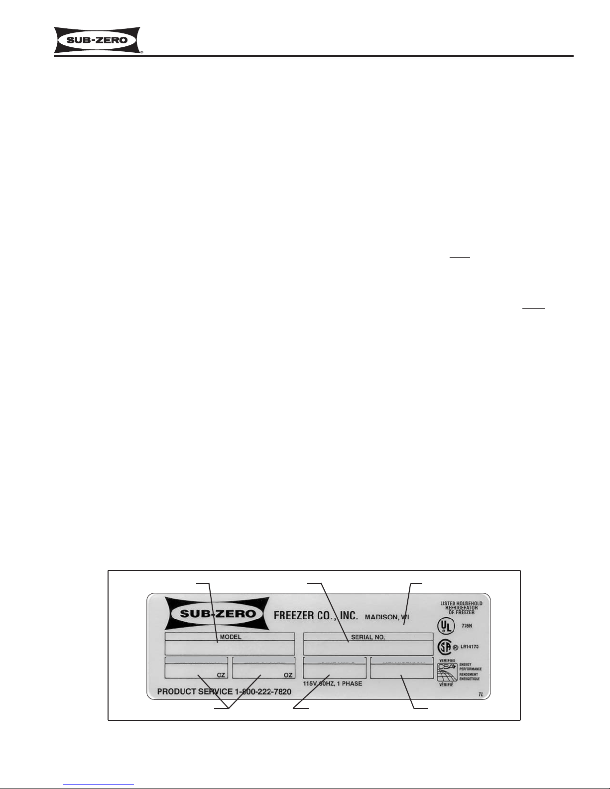
Figure 1-1. Serial Tag Layout (Layout Reference Only)
632 0000000
10.0
9.0 2.0 R-12
Jul 99
Model Number
Serial Number
Manufacture Date
Refrigerant Charge
Total Amps Refrigerant Type
REFRIGERATOR FREEZER TOTAL AMPS REFRIGERANT
Page 8
General Information
600 Series
(Prior to #1810000)
1-6
#3756270 - Revision B - January, 2006
NOTE: Functional parts are common to each model
configuration, meaning the models 601R/F, 601R/O and
601R/S will utilize common functional parts, just as the
models 601F/F, 601F/O and 601F/S will utilize common
functional parts, and so on... For this reason, the backward slash and letter at the end of the alpha-numeric
model number will be used in this manual only when
necessary.
Listed below are the twenty model numbers with a brief
description of that model.
MODEL DESCRIPTIONS
This section briefly describes the models covered in this
600 Series Service Manual. Though there are twenty
models, there are only seven basic model configurations (Models 601R, 601F, 611, 632, 642, 650, 690).
The reason for twenty different model numbers is the
three esthetic variations to the exterior components.
The letter after the backward slash in the alpha-numeric
model number indicates the exterior cosmetic variation.
(“/F” indicates a Framed
look with the door trim visible,
“/O” indicates that it is intended for the unit’s door panels to Overlay
the door trim, and “/S” indicates that the
unit is Stainless Steel.)
MODEL DESCRIPTION
601R/F 36” Wide, All-Refrigerator, Framed Door with handle, Louver Grille
601R/O 36” Wide, All-Refrigerator, Overlay Door Trim without handle, Louver Grille
601R/S 36” Wide, All-Refrigerator, Stainless Steel Door and Grille
601F/F 36” Wide, All-Freezer, Framed Door Trim with handle, Louver Grille
601F/O 36” Wide, All-Freezer, Overlay Door Trim without handle, Louver Grille
601F/S 36” Wide, All-Freezer, Stainless Steel Door and Grille
611/F 30” Wide, Over-and-Under, Framed Door Trim with handle, Louver Grille (Standard)
611/O 30” Wide, Over-and-Under, Overlay Door Trim without handle, Panel Grille (Standard)
611/S 30” Wide, Over-and-Under, Stainless Steel Doors and Grille
632/F 48” Wide, Side-by-Side, Framed Door Trim with handle, Louver Grille (Standard)
632/O 48” Wide, Side-by-Side, Overlay Door Trim without handle, Panel Grille (Standard)
632/S 48” Wide, Side-by-Side, Stainless Steel Doors and Grille
642/F 42” Wide, Side-by-Side, Framed Door Trim with handle, Louver Grille (Standard)
642/O 42” Wide, Side-by-Side, Overlay Door Trim without handle, Panel Grille (Standard)
642/S 42” Wide, Side-by-Side, Stainless Steel Doors and Grille
650/F 36” Wide, Over-and-Under, Framed Door Trim with handle, Louver Grille (Standard)
650/O 36” Wide, Over-and-Under, Overlay Door Trim without handle, Panel Grille (Standard)
650/S 36” Wide, Over-and-Under, Stainless Steel Doors and Grille
690/F 48” Wide, Side-by-Side, Ice & Water Dispenser, Framed Door Trim with handle,
Louver Grille, (Standard)
690/S 48” Wide, Side-by-Side with Ice & Water Dispenser, Stainless Steel Doors and Grille
NOTE: There is no overlay variation for the model 690, but an optional panel grille is available.
Page 9

Installation Information
600 Series
(Prior to #1810000)
2-1
#3756270 - Revision B - January, 2006
SECTION 2
INSTALLATION
INFORMATION
Page 10
Installation Information
600 Series
(Prior to #1810000)
2-2
#3756270 - Revision B - January, 2006
INSTALLATION CONSIDERATIONS
This section covers common installation issues seen by Service Technicians. Improper installation, though not a
valid service issue, has the potential to lead to a call for service. Installation related complaints could include, but
are not limited to: Unit leveling, unit movement, door misalignment, improper door and drawer sealing, internal frost
or condensation, exterior condensation, warm compartment temperatures, etc.
NOTE: If additional installation information is needed, refer to the complete Installation Manual, or contact Sub-Zero
Service Department.
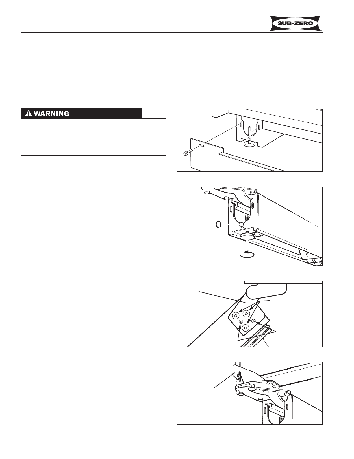
Unit Leveling (All Models)
NOTE: Unit must be installed before leveling (See
WARNING above). If unit is anchored to cabinets,
remove anchor screws before leveling, reinstalled after.
To level a unit, first remove kickplate (See Figure 2-1).
Then, to raise unit front, turn front leveler legs counterclockwise, clockwise to lower (See Figure 2-2).
At front of unit base is an adjusting screw that reaches
to rear leveler/roller assembly. To raise unit rear, use
5/16” socket wrench to turn adjusting screw clockwise
to raise, counterclockwise to lower (See Figure 2-2).
NOTE: Level is best checked at top & side mainframe.
Door Adjustment (All Models)
NOTE: Unit must be level before adjusting doors.
If unit is properly installed, blocked and leveled, it may
still be necessary to adjust door(s) left to right and/or in
and out. Adjustments are performed at top and/or bottom door hinge(s). Two small Phillips head shipping
screws in each door hinge must be removed and discarded before attempting adjustments. Then, working
on only one hinge at a time, loosen and re-snug door
hinge mounting screws, allowing door adjustment (See
Figure 2-3). After adjusting door, tighten door hinge
mounting screws and check for proper door seal.
NOTE: If one door on a side-by-side unit sits higher
than the other, bottom hinge spacer (part #0183100) is
available. To install spacer, remove shipping screws
from bottom door hinge, then loosen hinge mounting
screws. Insert spacer(s) between bottom door hinge
and bottom door trim. Adjust door accordingly and
retighten door hinge screws. (See Figure 2-4.)
Figure 2-2. Unit Leveling
UNIT COULD TIP UNDER CERTAIN LOAD CONDITIONS. FAILURE TO INSTALL ANTI-TIP COMPONENTS AND EXTEND LEVELERS TO FLOOR
ACCORDING TO INSTALLATION MANUAL COULD
RESULT IN SERIOUS INJURY OR DEATH.
Figure 2-3. Top Door Hinge & Screws
Top door
hinge
Loosen & re-snug
door hinge mounting
screws to allow door
adjustment
Discard shipping
screws
Figure 2-1. Kickplate Removal
Figure 2-4. Bottom Hinge Shim Installation
Hinge Shim
Part #0183100
Kickplate
Turn adjusting
screw clockwise
to raise rear.
Turn front levelers
counterclockwise
to raise front.
Unit Base
Page 11
Installation Information
600 Series
(Prior to #1810000)
2-3
#3756270 - Revision B - January, 2006
Special Side-by-Side Door Adjustment
Occasionally after a side-by-side unit is properly installed, blocked and leveled, the refrigerator door top may stick
out farther then the freezer door top, even though the bottom of each door is flush. The adjustment procedure listed
below explains how to correct this. (For video showing this procedure, order part #3756530)
NOTE: Unit must be level before adjusting doors.
Special Side-by-Side Door Adjustment Procedure:
1. First -
Adjust Refrigerator Door Bottom Hinge OUT:
a. Extract shipping screws from refrigerator door bottom hinge. Then, loosen & re-snug bottom hinge mounting
screws.
b. Pull refrigerator door bottom hinge corner out to outer most limit & tighten hinge mounting screws.
NOTE: Check door gasket seal by refrigerator door bottom hinge. If gasket is not sealing, loosen & re-snug
mounting screws, and push refrigerator door bottom hinge corner in slightly until gasket seals.
c. Check door alignment. If refrigerator door top still sticks out farther then freezer door, perform second adjust-
ment.
2. Second -
Adjust Refrigerator Door Top Hinge IN:
a. With a pencil, trace location of refrigerator door top hinge for reference. Extract shipping screws from refrigera-
tor door top hinge, then loosen & re-snug top door hinge mounting screws.
b. Push refrigerator door top hinge corner in to inner most limit & tighten hinge mounting screws.
NOTE: Check door gasket seal around refrigerator
door. If gasket is not sealing, adjust accordingly.
c. Check door alignment. If refrigerator door top still sticks
out farther then freezer door, perform third adjustment.
3. Third -
Adjust Freezer Door Top Hinge OUT:
a With a pencil, trace location of freezer door top hinge
for reference. Extract shipping screws from freezer
door top hinge, then loosen & re-snug top door hinge
mounting screws.
b. Pull freezer door top hinge corner out to outer most limit
& tighten hinge mounting screws.
NOTE: Check door gasket seal by freezer door top
hinge. If gasket is not sealing, loosen & re-snug mounting screws, and push freezer door top hinge corner in
slightly until gasket seals.
c. Check door alignment. If refrigerator door top still sticks
out farther then freezer door, perform fourth adjustment.
4. Fourth -
Adjust Freezer Door Bottom Hinge IN:
a. Extract Phillips head shipping screws from freezer door
bottom hinge. Then, loosen & re-snug bottom door
hinge mounting screws.
b. Push freezer door bottom hinge corner in to inner most
limit & tighten hinge mounting screws.
NOTE: Check door gasket seal around freezer door. If
gasket is not sealing, adjust accordingly.
c. Check door alignment. Minor adjustments may still be
needed at this point, adjust accordingly.
Figure 2-5. Special Side-by-Side Door Adjustment
2 - IN3 - OUT
4 - IN
1 - OUT
Page 12
Installation Information
600 Series
(Prior to #1810000)
2-4
#3756270 - Revision B - January, 2006
Freezer Drawer Adjustments
(Models 611 & 650)
NOTE: Before attempting freezer drawer adjustment,
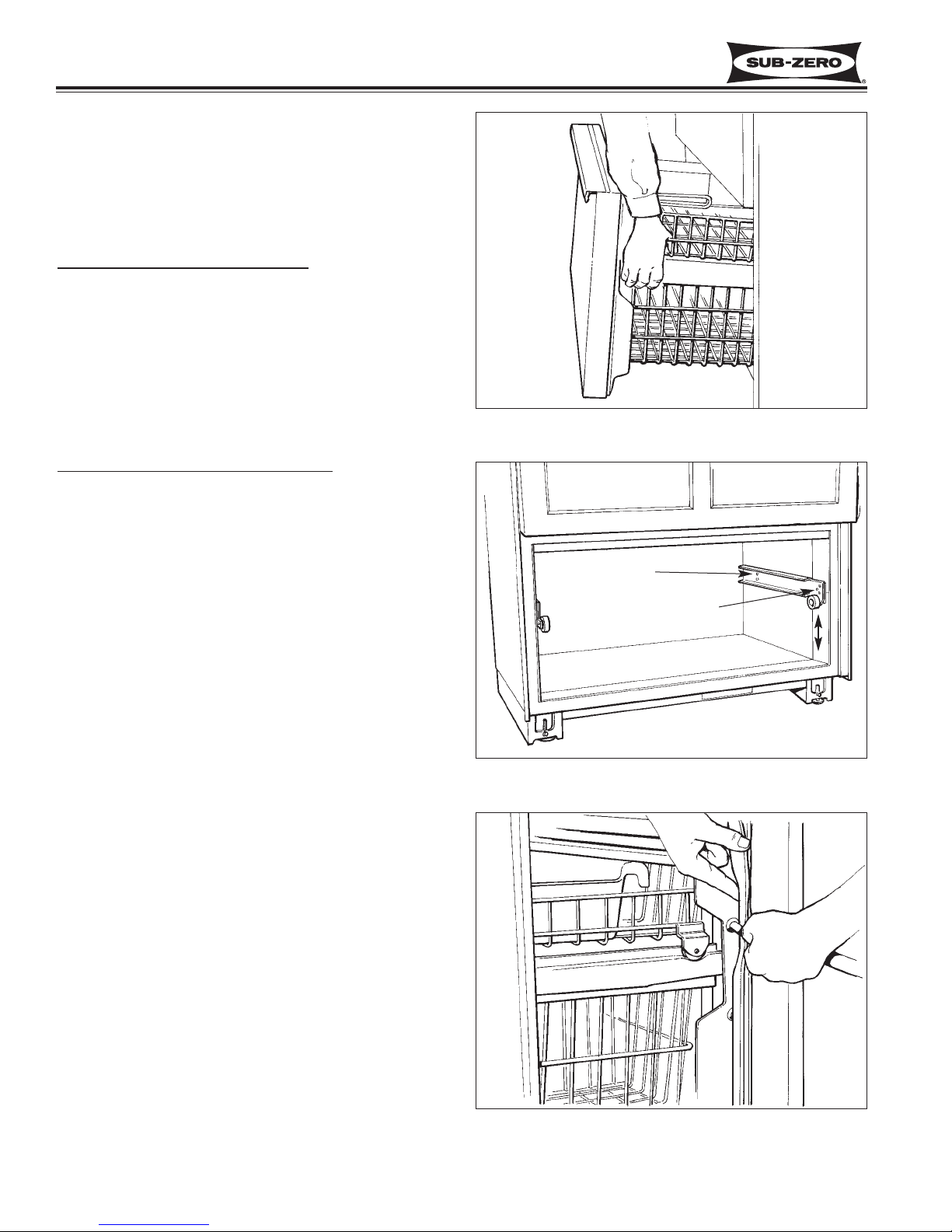
remove freezer drawer assembly. Pull drawer assembly out, then lift at front while holding upper freezer basket in place. (See Figure 2-6)
V
ertical Freezer Drawer Adjustment:
a. Loosen two screws towards rear of each cabinet
drawer slide, and extract screw at slide front. (See
Figure 2-7)
b. Relocate front screw to desired position in drawer
slide insulator grommet (See Figure 2-7).
c. After adjustment, tighten all screws, reinstall drawer
assembly, then check door seal for proper gasket
seating.
Freezer Drawer Front Pitch
Adjustment:
a. Remove two 3/4” white plastic plugs from each side
of plastic drawer liner. (See Figure 2-8)
b. With 3/8” socket, loosen bolts, then adjust drawer
front pitch accordingly. (See Figure 2-8).
c. After adjustment, tighten bolts and check door seal
for proper gasket seating.
NOTE: If freezer drawer assembly has too much play
from side-to-side, freezer drawer slide shims (part #
0232300 - front, part # 0232310 - rear) are available.
Figure 2-6. Drawer Assembly Removal
Figure 2-7. Vertical Freezer Drawer Adjustment
Rear Screws
Front Screw
Adjust slide front up
or down as required
Figure 2-8. Drawer Front Pitch Adjustment
Page 13
Installation Information
600 Series
(Prior to #1810000)
2-5
#3756270 - Revision B - January, 2006
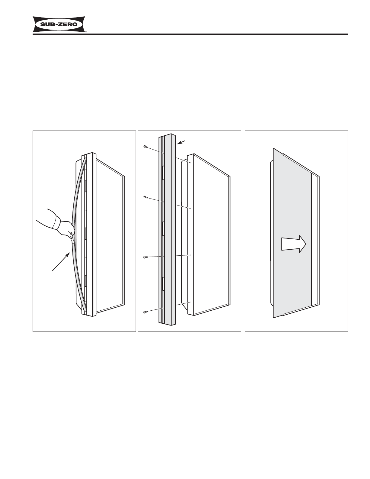
Door Panel Installation (All Models)
a. Using piece of tape stuck to magnetic trim molding center, pull trim molding out at midpoint to expose
handle/trim mounting screws (See Figure 2-9).
b. Extract mounting screws and handle/trim from door (See Figure 2-10).
c. Slide door panel into door frame (See Figure 2-11), then reinstalling handle/trim and magnetic trim molding.
NOTE: If door panel is less than 1/4” thick, a filler panel must be installed behind door panel.
NOTE: On Model 690, the handle inserts, trim fillers, vertical trim strip and glass well bezel will need to also be
removed from door before sliding door panel into door frame.
Figure 2-9. Molding Removal
Stick tape to
center of
trim molding
and pull
Extract screws and
handle/trim from door
Slide door panel into
door frame
Figure 2-10. Handle/Trim Removal Figure 2-11. Door Panel Install
D
o
r
o
D
o
r
o
D
o
o
r
P
a
n
e
l
Page 14
Installation Information
600 Series
(Prior to #1810000)
2-6
#3756270 - Revision B - January, 2006
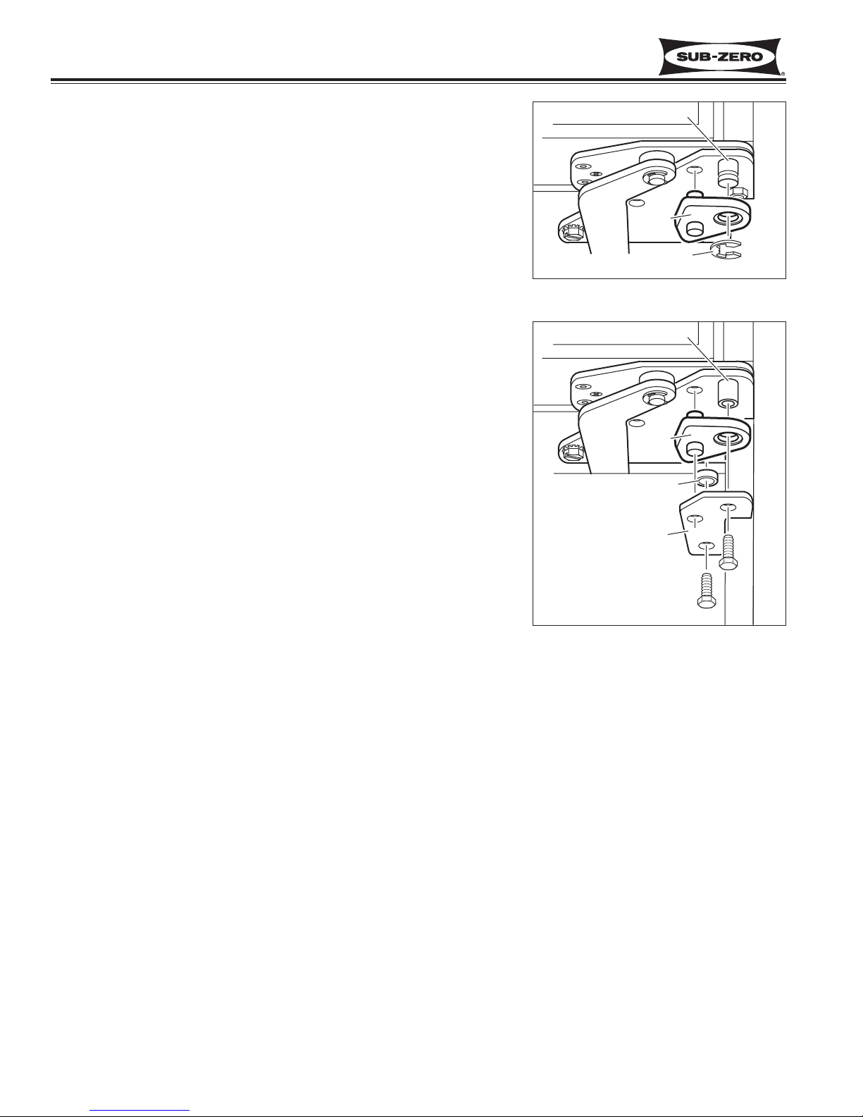
90° Door Stop Cam Installation (Models 601R, 601F)
Optional 90° door stop cam (part # DS90) and 105° door stop cam (part
# DS105) are available at no charge from Authorized Parts Distributors
and Product Distributors. To install (See Figure 2-13):
a With door closed, extract bolts, stiffener plate and bushing from
lower cabinet hinge.
b. Place door stop cam up over hinge pin, making sure stub on cam
fits into hole in lower cabinet hinge.
c. Reinstall bushing, stiffener plate and bolts onto lower cabinet hinge.
Figure 2-13. 90° Stop Cam
Figure 2-12. 90° Stop Cam
90° Door Stop Cam Installation (Models 632, 642, 690)
Optional 90° door stop cam (part # DS90) and 105° door stop cam (part
# DS105) are available at no charge from Authorized Parts Distributors
and Product Distributors. To install (See Figure 2-12):
a With door closed, place door stop cam up over hinge pin, making
sure stub on cam fits into hole in lower cabinet hinge.
b. Secure door stop cam by pushing E-ring into groove at end of hinge
pin.
HINGE PIN
90° DOOR
STOP CAM
E-RING
HINGE PIN
90° DOOR
STOP CAM
BUSHING
STIFFENER
PLATE
Page 15

Electronic Control System
600 Series
(Prior to #1810000)
3-1
#3756270 - Revision B - January, 2006
SECTION 3
ELECTRONIC CONTROL
SYSTEM INFORMATION
Page 16
Electronic Control System
600 Series
(Prior to #1810000)
3-2
#3756270 - Revision B - January, 2006
ELECTRONIC CONTROL TERMINOLOGY & COMPONENT DESCRIPTIONS
All 600 Series units utilize an electronic control system. The electronic control system monitors, regulates and controls a variety of functions, as well as displaying temperatures and possible problems with the unit. In this section,
some basic electronic control system terminology is defined, and electronic control components described. An
understanding of the following information is needed in order to comprehend the electronic control system.
TERM / COMPONENT DEFINITION / DESCRIPTION
Control Board The electronic board which contains the microprocessor, relays, electrical connec-
tions and LCD. The electrical hub of the electronic control system.
NOTE: See "Control Board Summary / Layout" in following section.
Microprocessor An electrical component on the control board which receives electrical signals from
other components in the electronic control system, processes that information, and
then sends an electrical signal to the relays instructing them to open or close, and
other electronic components to switch on or off.
Relay The electrical components on the control board which, when closed, allow power to
the appropriate components.
LCD (Liquid Crystal Display) That part of the control board seen at the control panel which displays compartment
temperatures, service indicators, etc...
Control Panel The information input and read-out area of the electronic control system. The LCD
is visible through a window on the control panel.
Membrane Switch That part of the upper control panel where all input functions are performed.
Keys Buttons on the Membrane switch used for input functions.
Indicators The words that are displayed on the LCD.
Set-Point The desired compartment temperature. This is the approximate average of the high
offset and the low offset.
High Offset The maximum compartment air temperature the electronic control system will allow.
When the high offset is reached, power is supplied to the compressor to run.
Low Offset The minimum compartment air temperature the electronic control system will allow.
When the Low Offset is reached, power to the compressor is interrupted.
Offset Temperature Range The difference between the low offset and the high offset.
Thermistor A resistor with which resistance changes as the temperature around it changes. For
electronic control system purposes, the microprocessor deciphers this resistance
signal as temperature.
(Temperature Sensor)
Page 17
Electronic Control System
600 Series
(Prior to #1810000)
3-3
#3756270 - Revision B - January, 2006
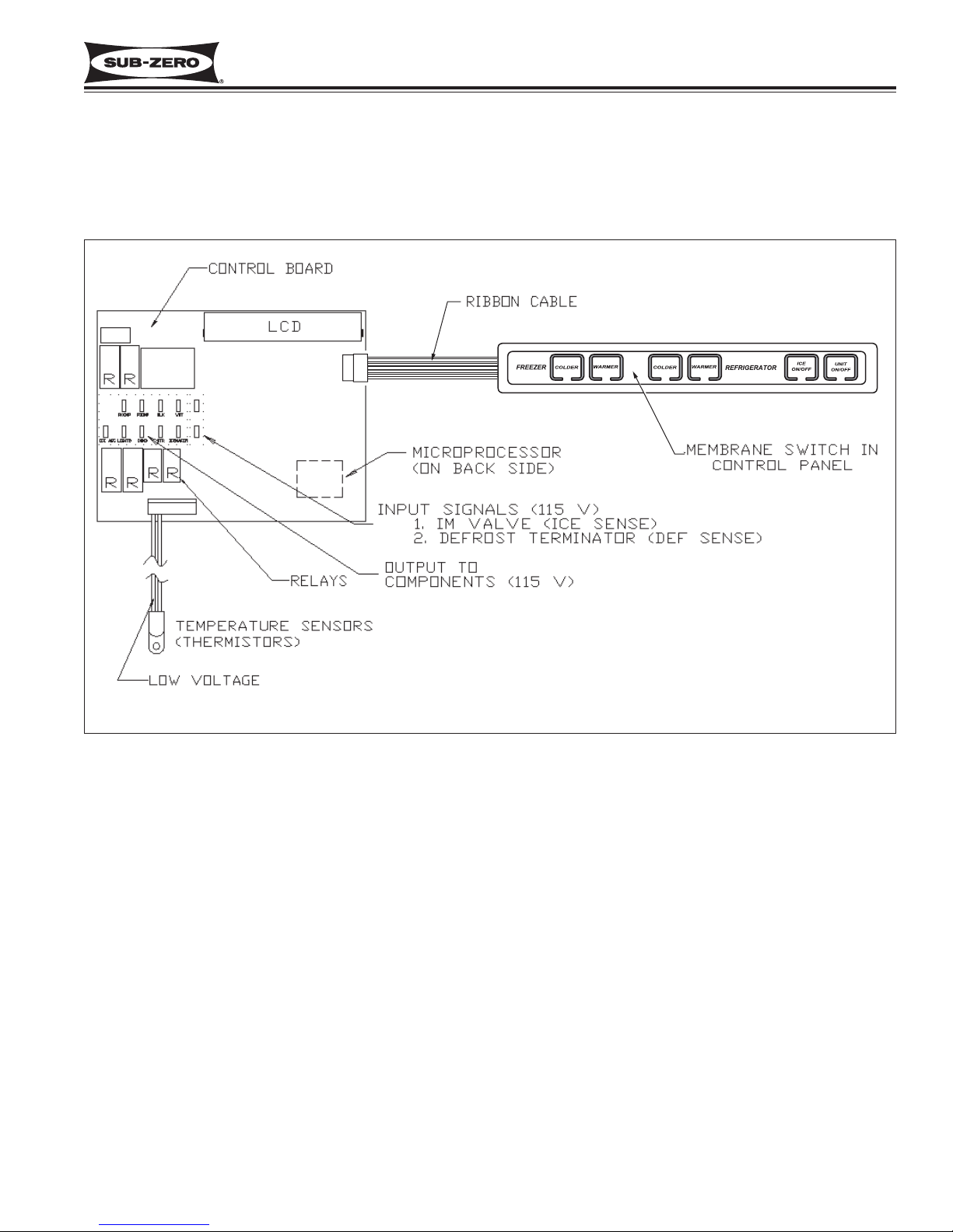
BASIC ELECTRONIC CONTROL SYSTEM
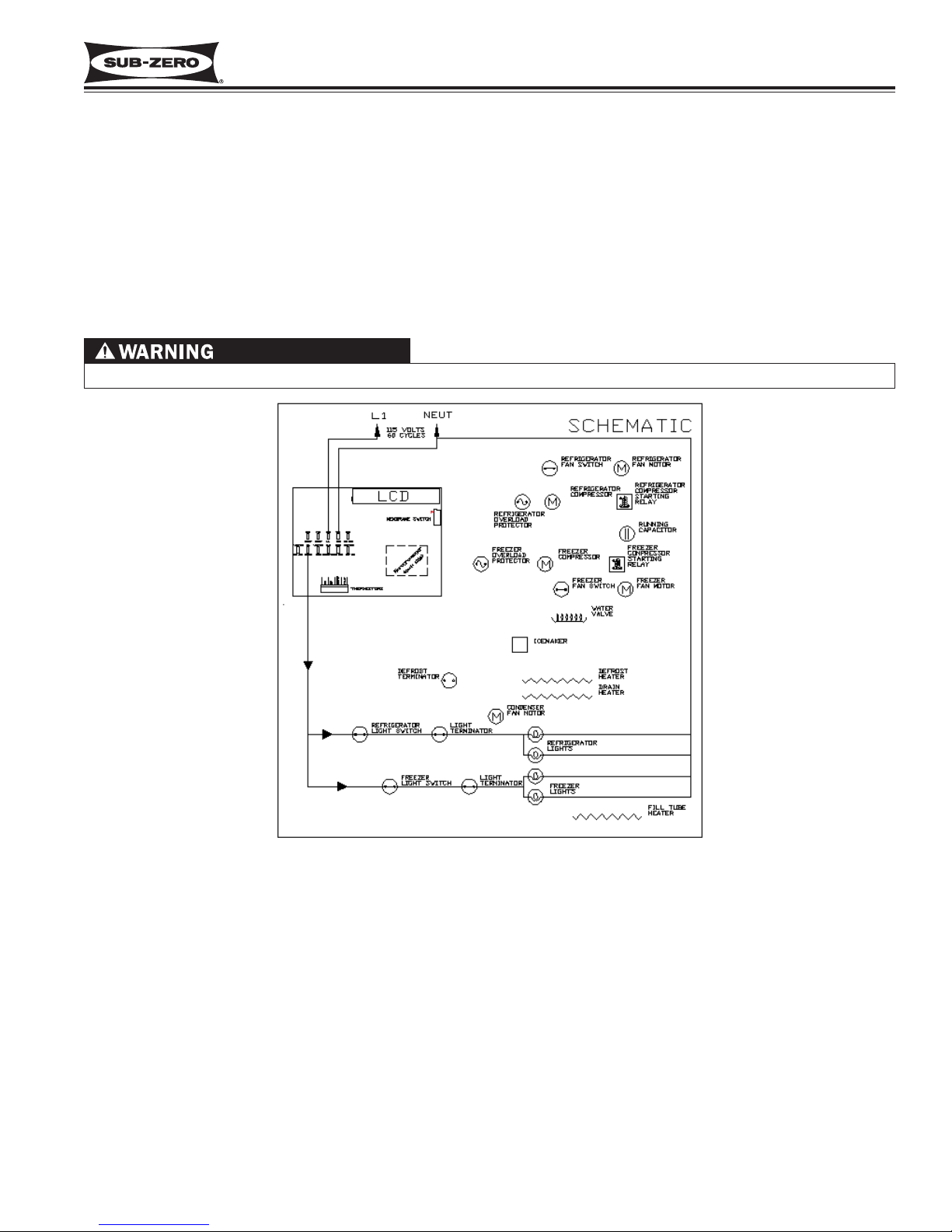
Input operations for the electronic control system are performed at the control panel, with monitoring, regulating and
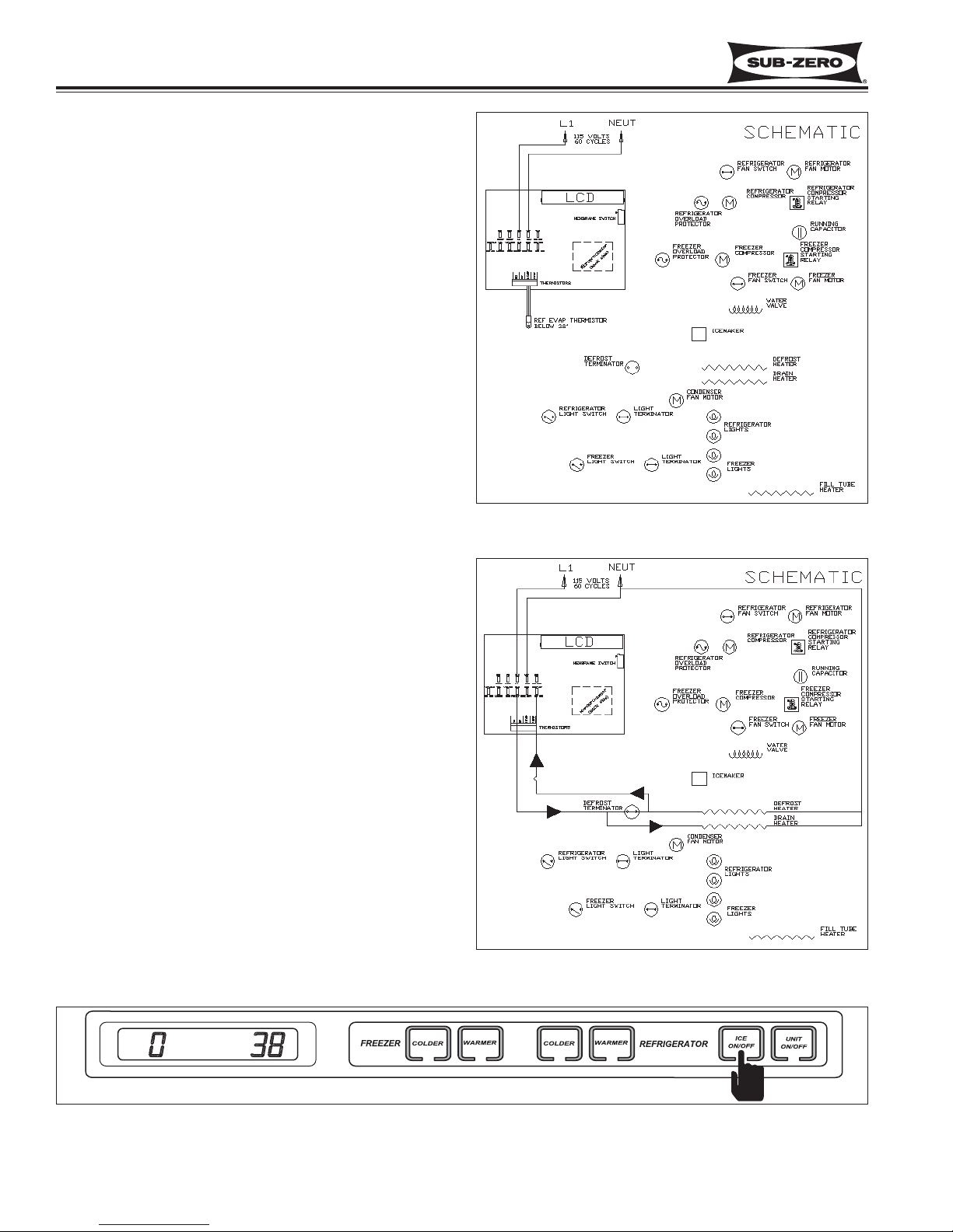
controlling functions taking place at the control board. Temperatures and possible problems with the unit are illuminated on the LCD. This page illustrates a basic electronic control system (See Figure 3-1).
Figure 3-1. Basic Electronic Control System
Page 18
Electronic Control System
600 Series
(Prior to #1810000)
3-4
#3756270 - Revision B - January, 2006
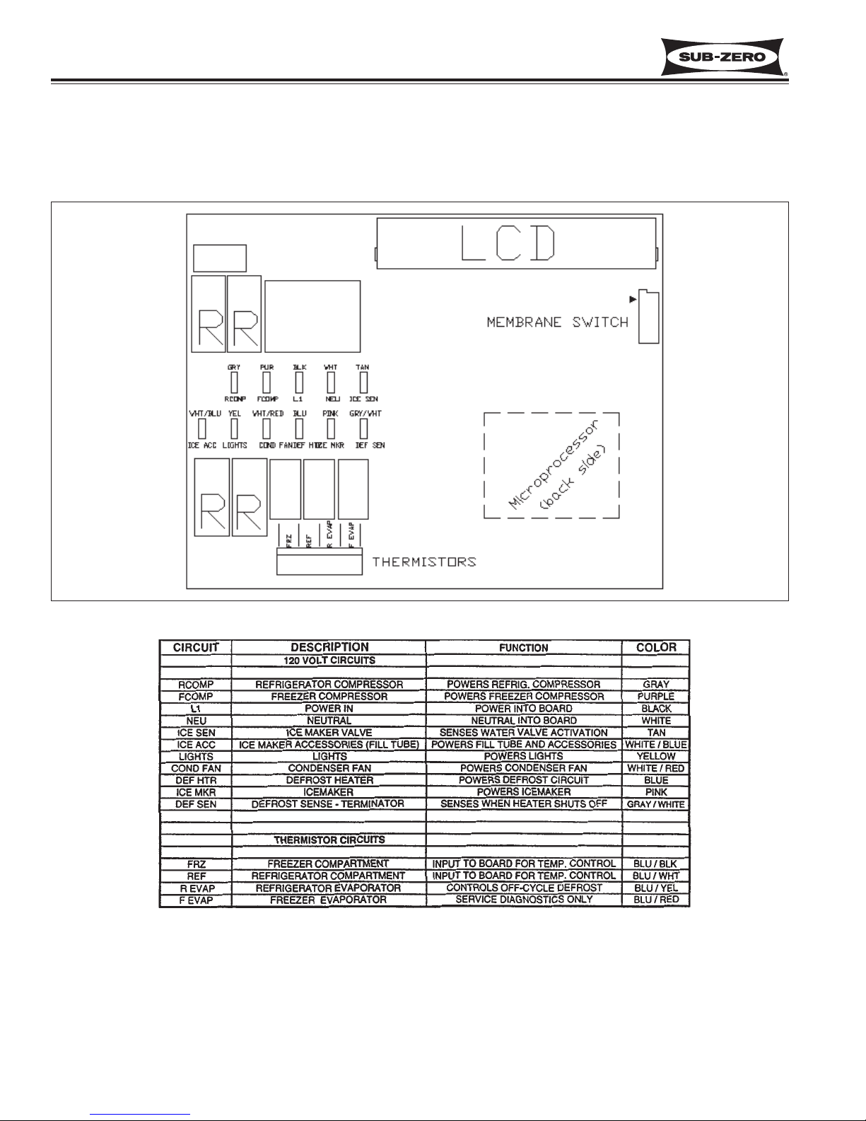
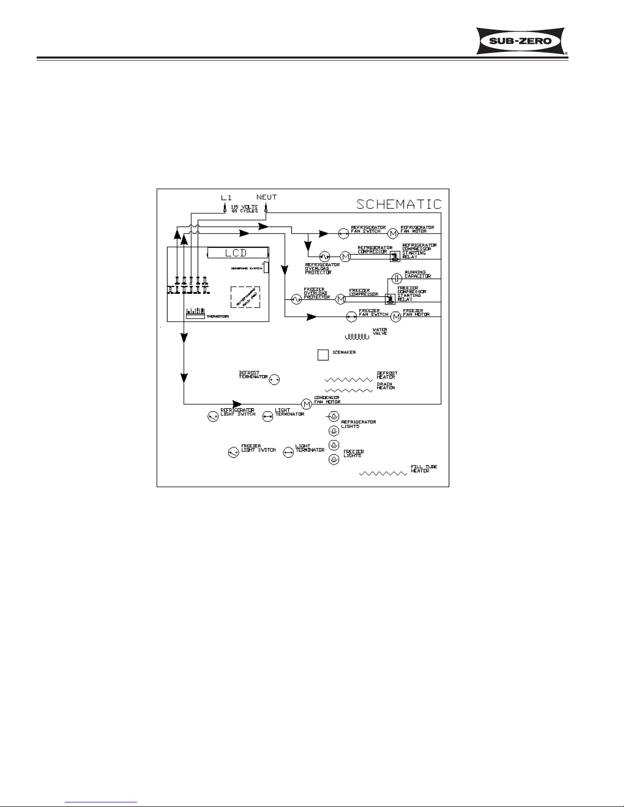
Control Board Summary / Layout
The electrical connection points on the control board are labeled, indicating which components are connected at
which connection points. Below is a layout diagram of the control board, followed by a summary table.
NOTE: All components on the control board are non-replaceable.
Figure 3-2. Control Board Diagram
Figure 3-3. Control Board Summary Table
Page 19
Electronic Control System
600 Series
(Prior to #1810000)
3-5
#3756270 - Revision B - January, 2006
Figure 3-5. Temperature Adjustment
Figure 3-4. Unit Power ON/OFF
When in OFF mode, 115 Volts are still present at the control board.
Basic Input Operations
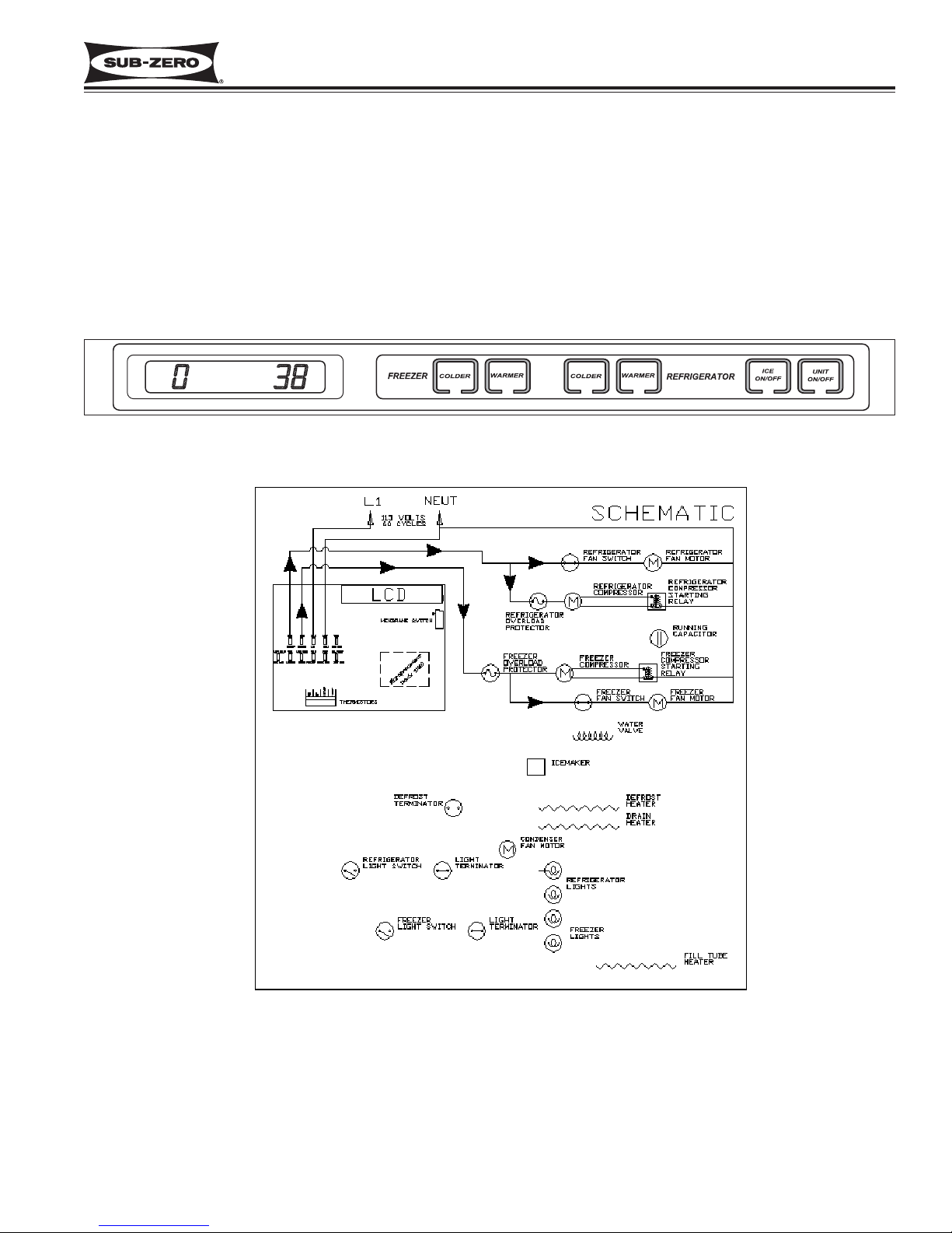
This section illustrates the basic input operations performed at the control panel. Switching the unit on & off, temperature adjustment, and switching the icemaker system on & off will be explained.
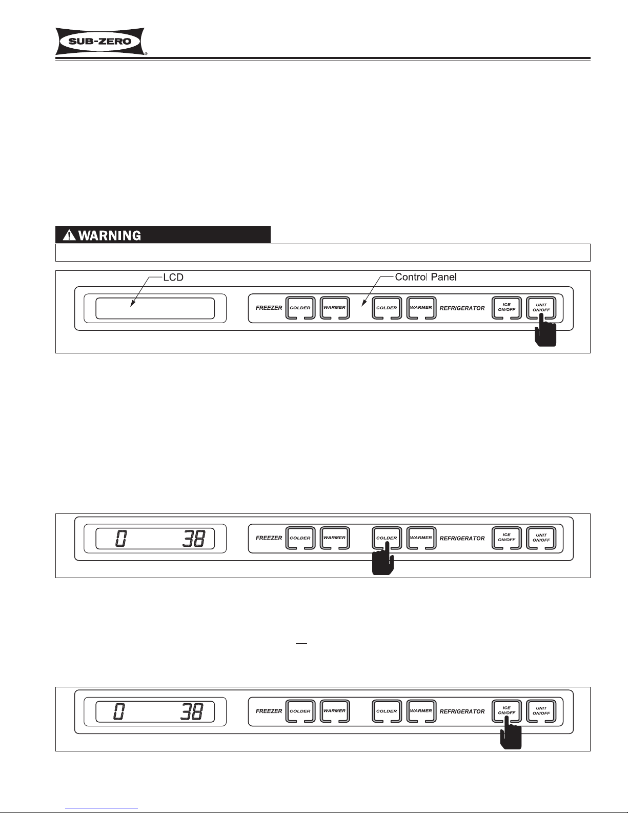
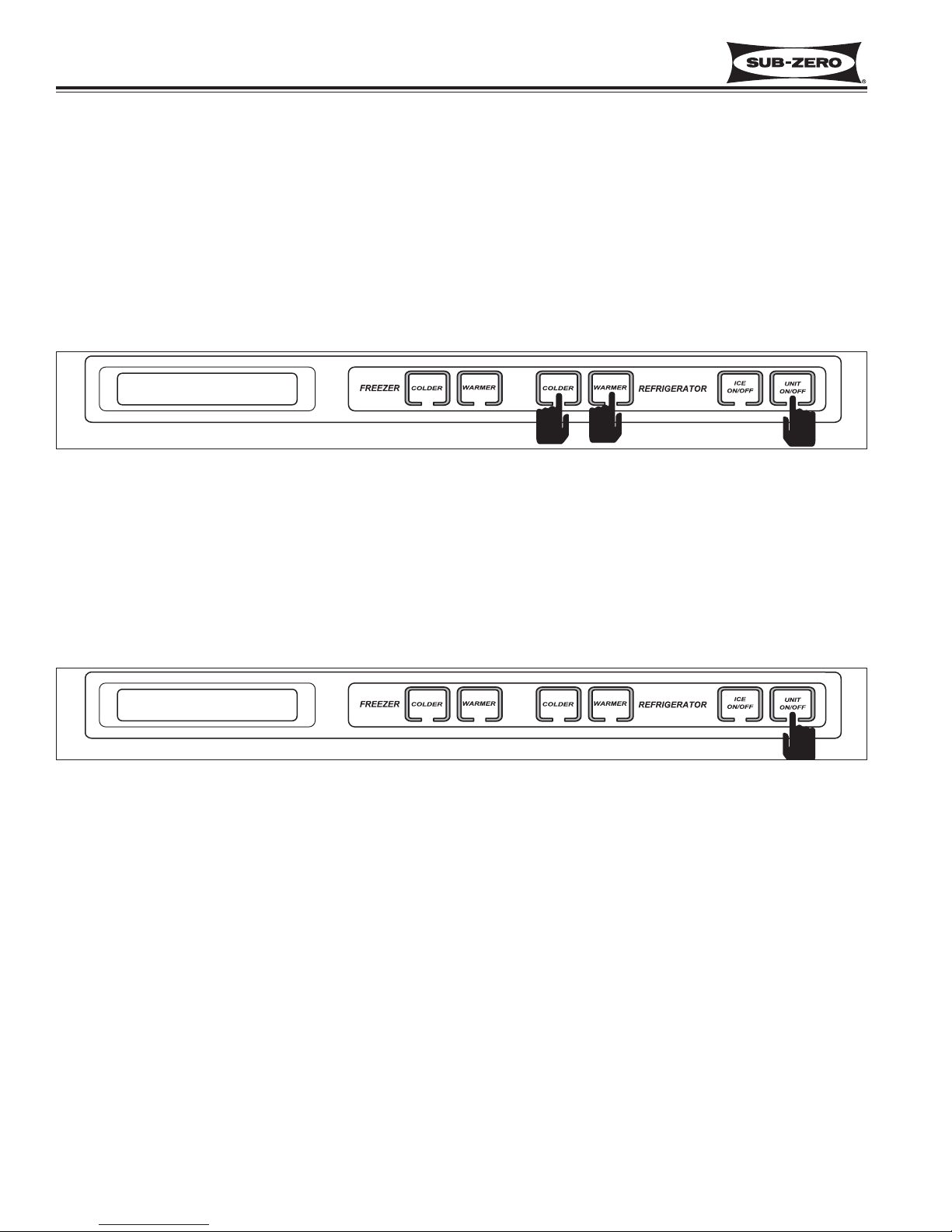
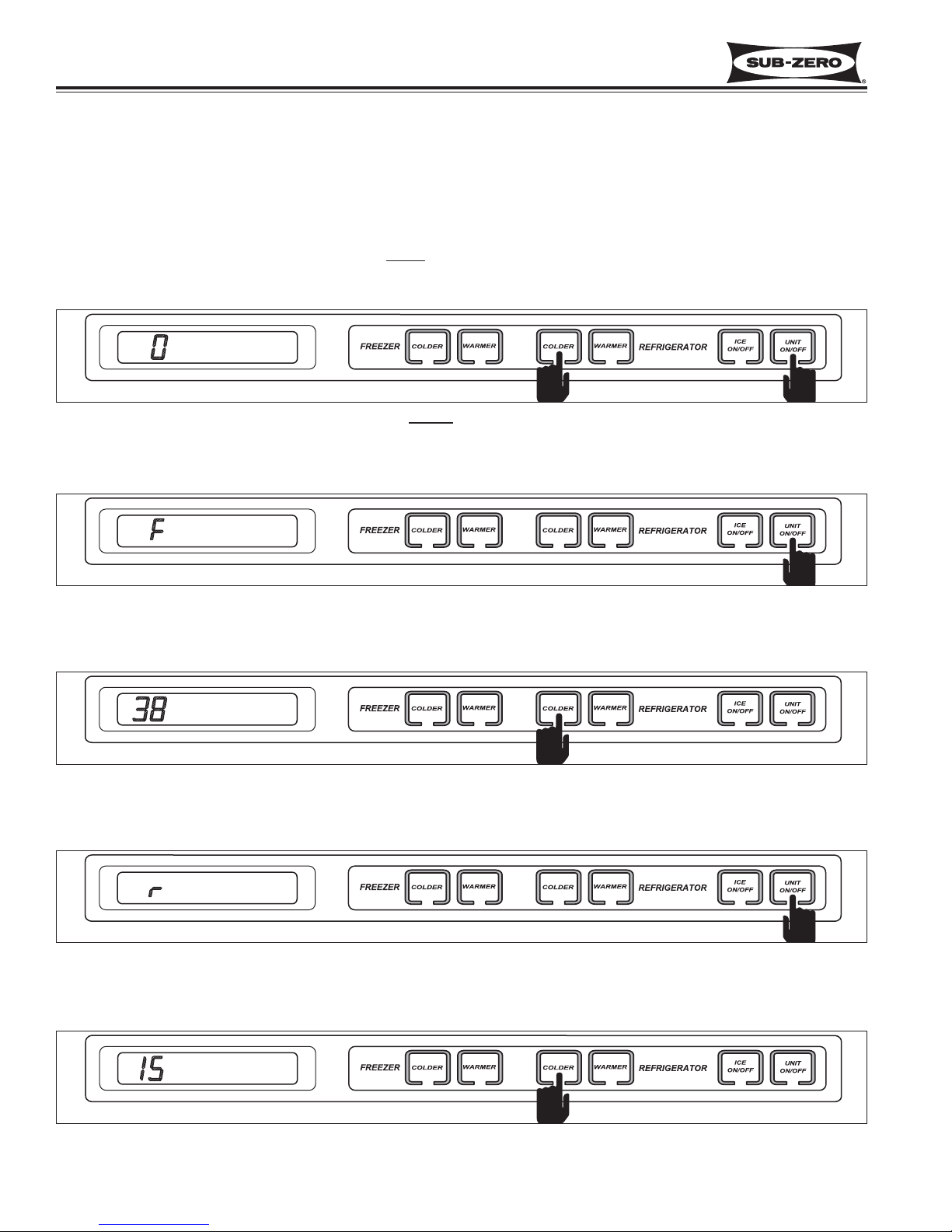
POWER ON/OFF
All 600 Series units arrive in Off Mode, and “OFF” is visible on the LCD. By pressing the UNIT ON/OFF key at this
time (See Figure 3-4.), “OFF” disappears from the LCD as power is allowed past the control board to the rest of the
unit, and the compartment temperatures are displayed.
NOTE: Whenever the last stroke of the UNIT ON/OFF key is off, “OFF” will be visible on the LCD.
TEMPERATURE ADJUSTMENT (ADJUSTING SET-POINT)
To adjust the compartment temperature, press the WARMER or COLDER keys on the control panel in multiple key
strokes until the desired set-point is achieved. One key stroke equals a 1° F change. (See Figure 3-5.)
NOTE: Freezer temperature range is -5° F to +5° F, with an initial Set Point of 0° F; Refrigerator temperature range
is 34° F to 45° F, with an initial Set Point of 38° F.
NOTE: Set-point will be displayed for 10 seconds after the last WARMER or COLDER key stroke, then the compartment temperature will appear. As the compartment temperature changes, the temperature displayed on the LCD will
change, by no more than 1° F per minute.
Icemaker System ON/OFF
All 600 Series units arrive with the icemaker system of
f. By pressing the ICE ON/OFF key at this time, power is
allowed to the icemaker system, and “ICE” is displayed on the LCD. (See Figure 3-6.)
NOTE: Also see “Sabbath Mode” in UNIQUE INPUT OPERATIONS section.
Figure 3-6. Icemaker System ON/OFF
OFF
ICE
Page 20
Electronic Control System
600 Series
(Prior to #1810000)
3-6
#3756270 - Revision B - January, 2006
UNIQUE INPUT OPERATIONS
This section illustrates electronic control input operations not associated with typical unit function.
Show Room Mode
Showroom Mode was incorporated into the electronic control system so these appliances could be displayed in a
showroom setting. With power to the unit, initiate showroom mode by pressing the UNIT ON/OFF key so that “OFF”
is appears on the LCD. With “OFF” displayed, press and hold the WARMER, COLDER keys, then the UNIT
ON/OFF key (See Figure 3-7). This disables all but the lighting system. To return to normal operating condition,
repeat the above steps.
NOTE: Always recheck set-points after returning unit to normal operating condition.
Figure 3-7. Show Room Mode - Press UNIT ON/OFF Key.
Then, Press and Hold WARMER, COLDER Keys, then Press the UNIT ON/OFF Key.
Sabbath Mode
Sabbath Mode was incorporated into the electronic control sysyem for the observence of certain religeous days.
Sabbath Mode disables the lights and icemaker switches. With the unit on, initiate Sabbath Mode by pressing the
UNIT ON/OFF key so that OFF is displayed on the LCD. Then press and hold the UNIT ON/OFF key for 10 seconds (See Figure 3-8). To return unit to normal operating condition, press and release the UNIT ON/OFF key.
Figure 3-8. Sabbath Mode - Press and Hold for 10 Seconds
OFF
OFF
Page 21
Electronic Control System
600 Series
(Prior to #1810000)
3-7
#3756270 - Revision B - January, 2006
Figure 3-9. Lighting System Signal Trace
When in OFF mode, 115 Volts are still present at the control board.
FUNCTIONS OF ELECTRONIC CONTROL SYSTEM
This section covers the monitoring, regulating and controlling functions of the electronic control system.
NOTE: All electronic control system functions described in this section are normal operation only. Malfunctions will
be covered in later sections.
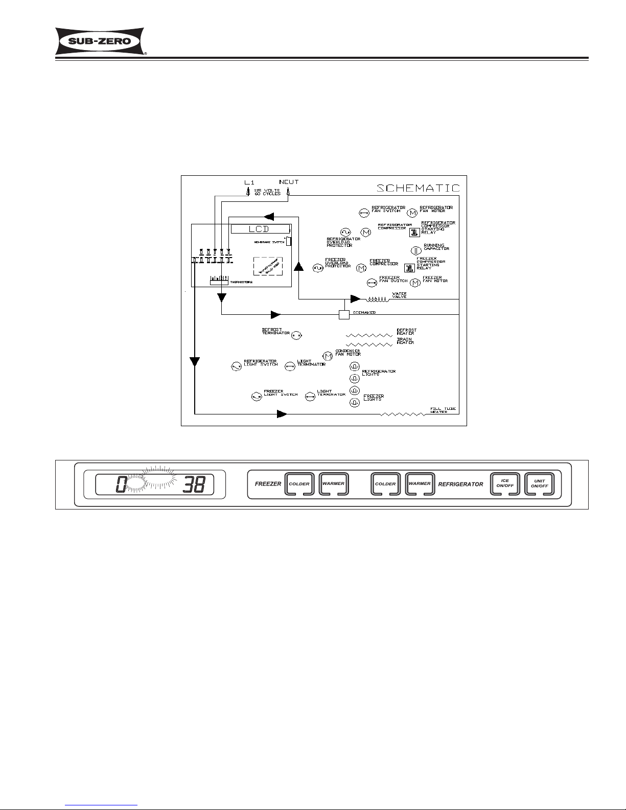
Supply Power to the Lighting System
115 Volts is supplied to the lighting system through the control board. (See Figure 3-9)
NOTE: Disabling the lighting system (Sabbath Mode) is covered in the UNIQUE INPUT OPERATIONS section.
Page 22
Electronic Control System
600 Series
(Prior to #1810000)
3-8
#3756270 - Revision B - January, 2006
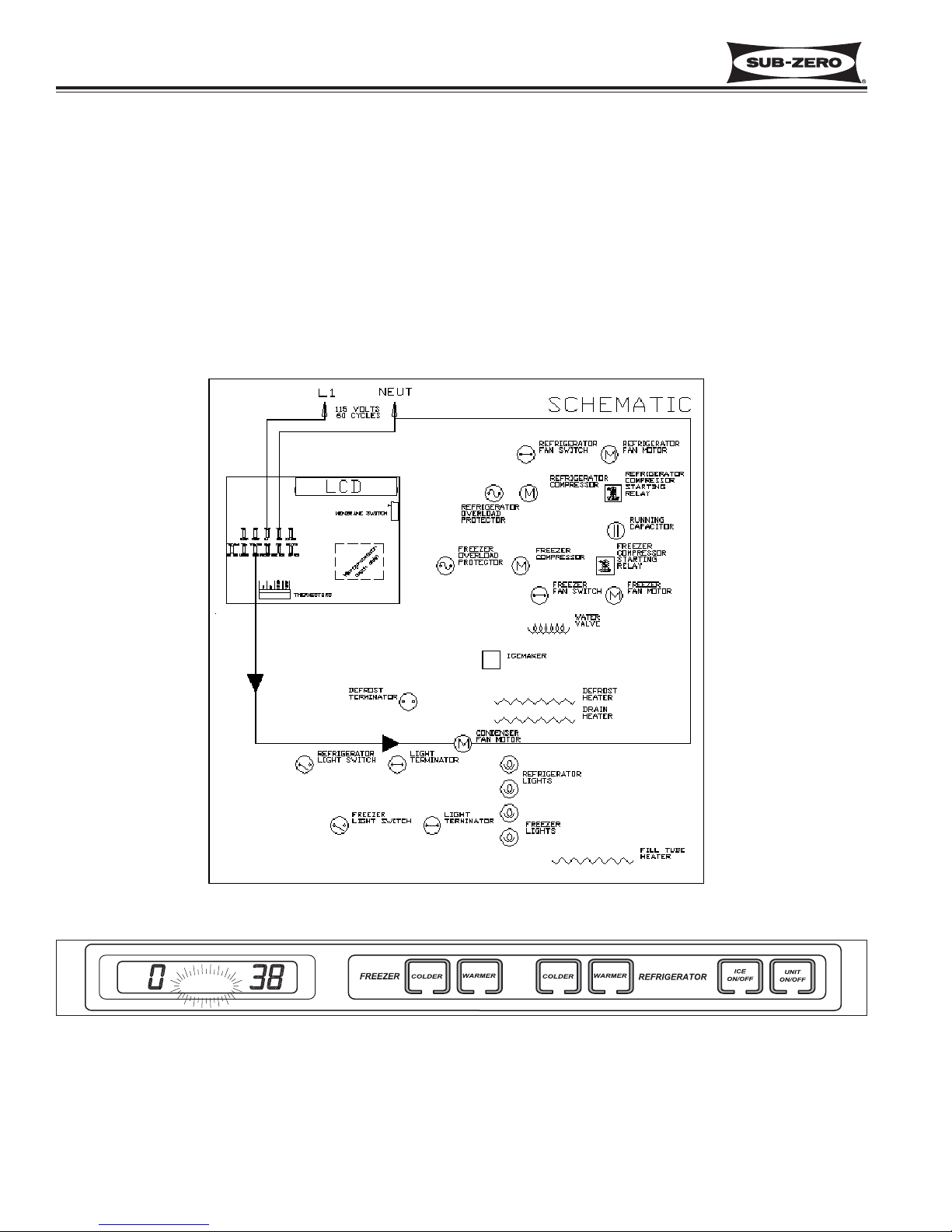
Figure 3-10. Condenser Fan Power Signal Trace
Control Condenser Fan Operation (Models 611, 632, 642, 650, 690)
NOTE: Power to the condenser fan on models 601R and 601F is supplied direct from the compressor.
The microprocessor senses the 115 volt output supplied to both compressors. If either compressor is running, a signal is sent to the condenser fan relay on the control board to close, supplying power to the condenser fan. If both
compressors are off, the condenser fan is off. (See Figure 3-10)
NOTE: The condenser fan will run 100% if the VACUUM CONDENSER indicator is activated, This will be discussed in
MONITORS COMPRESSOR RUN DURATION.
Page 23
Electronic Control System
600 Series
(Prior to #1810000)
3-9
#3756270 - Revision B - January, 2006
Figure 3-12. Compressor Power Signal Trace
Figure 3-11. Temperature Display
Monitor, Display and Regulate Temperatures
The temperature signal from the thermistor in the refrigerator and/or freezer compartment is monitored by the microprocessor, and displayed on the LCD. Though the compartment air temperature does fluctuate, the LCD displays
the average temperature. (See Figure 3-11) When the compartment temperature reaches high offset, the signal is
sent to the compressor relay on the control board to close. This allows power to be supplied to the compressor and
evaporator fan, which cycle on. (See Figure 3-12) As the compressor and evaporator fan run, the compartment temperature drops. When the compartment temperature reaches low offset, the signal is sent to the compressor relay
on the control board to open. This interrupts power to the compressor and evaporator fan, cycling them off.
NOTE: If the compartment temperature should ever exceed either the high offset or low offset (for example: when a
door is left open), the temperature displayed on the LCD will change by one degree per minute.
Page 24
Electronic Control System
600 Series
(Prior to #1810000)
3-10
#3756270 - Revision B - January, 2006
Figure 3-13. Refrigerator Compressor OFF
Figure 3-14. Defrost Heater Signal Trace
Monitor and Control Rerigerator Off-cycle Defrost
Temperature signals from the refrigerator compartment
thermistor and evaporator thermistor are monitored by
the microprocessor. If the compartment temperature
reaches high offset before the evaporator rises to 38°F,
the command to start the compressor will wait, allowing
the evaporator to fully defrost before the compressor is
energized. (See Figure 3-13)
Monitor and Control Freezer “Adaptive Defrost”
Initially the freezer compressor in a 600 Series unit will
cycle-run for 12 hours, after which the microprocessor
sends the signal to the defrost relay on the control
board to close. This supplies power to the defrost
heater, and the compressor is switched off. (See
Figure 3-14) With the “Adaptive Defrost” technique, the
length of time that the heater actually stays on to
defrost the evaporator and satisfy the defrost terminator
is observed by the microprocessor. The microprocessor then determines the number of hours before the
next defrost. If the heater stays on for a shorter time
than specified, the microprocessor increases the next
defrost interval. If the heater stays on longer than specified, the electronic control decreases the next defrost
interval. This is an ongoing process whereby the
defrost time and the defrost interval will vary by unit
use.
NOTE: A five (5) minute delay/dwell follows all defrosts.
NOTE: Minimum defrost interval = six (6) hours;
Maximum defrost duration = twenty-five (25) minutes.
Initiating Freezer Manual Defrost
To manually initiate freezer evaporator defrost, press
and hold the ICE key at the control panel for ten seconds. (See Figure 3-15).
NOTE: To observe the initiation of manual defrost,
“ICE” must be displayed on the LCD. Then press and
hold the ICE key for ten seconds. At first, “ICE” will disappear. After ten seconds of holding the ICE key, “ICE”
will appear again, indicating manual defrost has begun.
Figure 3-15. Push and Hold ICE Key for 10 Seconds to initiate Manual Defrost
ICE
Page 25
Electronic Control System
600 Series
(Prior to #1810000)
3-11
#3756270 - Revision B - January, 2006
Figure 3-16. Water Valve Monitored.
Figure 3-17. ICE and SERVICE Indicators Flashing = Water Valve Energized Too Long
Monitor Icemaker System and Display If Service Is Needed.
The microprocessor monitors the voltage supplied to the icemaker water valve (See Figure 3-16). If the water valve
is energized for more than fifteen (15) seconds, power to the icemaker system is interupted, and a signal is sent to
the SERVICE and ICE indicators on the LCD to flash (See Figure 3-17).
NOTE: To allow ice to freeze fully and reduce effects of low water pressure, the electronic control system disables
the icemaker system for 45 minutes after each ice harvest.
SERVICE
ICE
Page 26
Electronic Control System
600 Series
(Prior to #1810000)
3-12
#3756270 - Revision B - January, 2006
Monitor Compressor Run Duration, Displays If Service, or Condenser Cleaning Is Needed
The microprocessor senses the 115 volt output supplied to both compressors, monitoring the length of compressor
run time (See Figure 3-18).
If several excessive compressor run periods occur, the microprocessor closes the condenser fan relay on the control
board, allowing the condenser fan to run 100%. A signal is then sent to the VACUUM CONDENSER indicator on
the LCD to flash (See Figure 3-19).
NOTE: Please keep in mind that a flashing VACUUM CONDENSER indicator is caused by excessive compressor
run, which could be related to problems other than a dirty condenser. This will be covered in the
TROUBLESHOOTING GUIDE.
NOTE: After correcting the cause of the error, the unit must be switched OFF, and back ON to clear the error indicator.
Figure 3-18. Compressor Run-Time Sensed
Figure 3-19. VACUUM CONDENSER Indicator Flashing = Excessive Compressor Run
VACUUM
CONDENSER
Page 27
Electronic Control System
600 Series
(Prior to #1810000)
3-13
#3756270 - Revision B - January, 2006
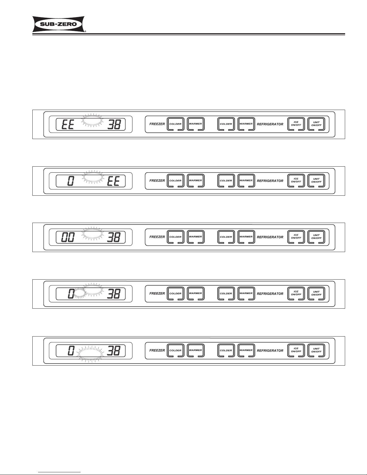
Figure 3-20. “EE” Displayed for Freezer Temp. with “SERVICE”
Flashing = Freezer Compartment Thermistor Faulty
Figure 3-21. “EE” Displayed for Refrigerator Temp. with “SERVICE”
Flashing = Refrigerator Compartment Thermistor Faulty
Figure 3-22. Freezer and Refrigerator Temps OK with “SERVICE”
Flashing = Refrigerator Evaporator Thermistor Faulty or Line Separated
POSSIBLE ERROR DISPLAYS
The diagrams below illustrate what a customer may see on the LCD if there is a problem/error with the unit. Below
each diagram is a description of what could be causing the error indicator. (See Figures 3-20 through 3-24.)
NOTE: “EE” indicates a thermistor error.
NOTE: To clear an error display, the cause must be corrected, then the unit switched off and back on with the UNIT
ON/OFF key.
Figure 3-23. Freezer and Refrigerator Temps OK with “SERVICE” and “ICE”
Flashing = Water Valve Energized Too Long
Figure 3-24. “VACUUM CONDENSER” Flashing = Excessive Compressor Run, Possible Condenser Cleaning
Needed, but Could Be a Result of Other Problems Which Cause Excessive Compressor Run
NOTE: To clear error indicators, the cause must be corrected and the unit must be switched off, then back on using
the UNIT ON/OFF key.
SERVICE
SERVICE
SERVICE
SERVICE
ICE
VACUUM
CONDENSER
Page 28
Electronic Control System
600 Series
(Prior to #1810000)
3-14
#3756270 - Revision B - January, 2006
DIAGNOSTIC MODE PROCEDURES
Diagnostic Mode was incorporated into the electronic control system to help troubleshoot various electrical, mechanical and sealed system components. This section explains Diagnostic Mode and illustrates the operations performed
at the control panel for troubleshooting purposes.
Follow the steps below to initiate and use the Diagnostic Mode.
1. To initiate diagnostic mode, press and hold either
COLDER key, then press the UNIT ON/OFF key. All indicators
on the LCD will light-up, indicating diagnostic mode is now active. Thehe first reading on the LCD will be the
freezer compartment temperature (See Figure 3-25).
Figure 3-25. Initiating Diagnostic Mode - Press Either
COLDER Key and UNIT ON/OFF Key simultaneously
Figure 3-26. Press UNIT ON/OFF Key to Display Location of Thermistor
2. Press the UNIT ON/OFF key at this time to display the location of the thermistor being read, “F” represents the
freezer compartment (See Figure 3-26).
Figure 3-27. Press COLDER Key to Display Temperature Reading
Figure 3-28. Press UNIT ON/OFF Key to Display Location of Thermistor
Figure 3-29. Press COLDER Key to Display Temperature Reading
3. Press the COLDER key now to display the second reading, the refrigerator compartment temperature (See
Figure 3-27).
4. Press the UNIT ON/OFF key at this time to display the location of the thermistor being read, “r” represents the
refrigerator compartment (See Figure 3-28).
5. Press the COLDER key now to display the third reading, which will be the refrigerator evaporator temperature
(See Figure 3-31).
SERVICE
ICE
VACUUM
CONDENSER
OFF
SERVICE
ICE
VACUUM
CONDENSER
OFF
SERVICE
ICE
VACUUM
CONDENSER
OFF
SERVICE
ICE
VACUUM
CONDENSER
OFF
SERVICE
ICE
VACUUM
CONDENSER
OFF
Page 29
Electronic Control System
600 Series
(Prior to #1810000)
3-15
#3756270 - Revision B - January, 2006
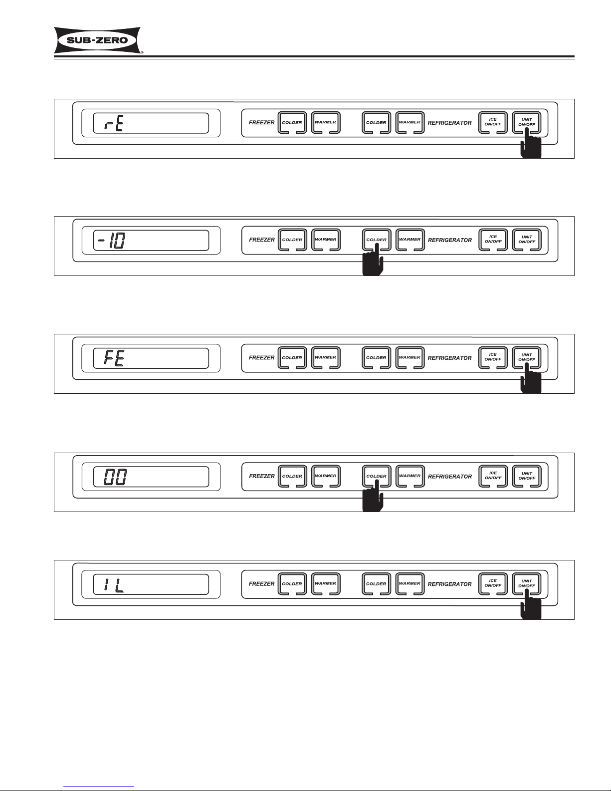
6. Press the UNIT ON/OFF key at this time to display the location of the thermistor being read, “rE” represents the
refrigerator evaporator temperature (See Figure 3-30).
Figure 3-34. Press UNIT ON/OFF Key to Display Inactive Line
Figure 3-31. Press COLDER Key to Display Temperature Reading
Figure 3-30. Press UNIT ON/OFF Key to Display Location of Thermistor
Figure 3-32. Press UNIT ON/OFF Key to Display Location of Thermistor
Figure 3-33. Press COLDER Key to Display Last Reading
7. Press the COLDER key now to display the fourth reading, which will be the freezer evaporator temperature (See
Figure 3-31).
8. Press the UNIT ON/OFF key at this time to display the location of the thermistor being read, “FE” represents the
freezer evaporator (See Figure 3-32).
9. Press the COLDER key now to display the fifth reading. This fifth reading should be “00” because it is inactive. This
area of the electronic control system is intended for possible future use (See Figure 3-33).
10. Pressing the UNIT ON/OFF key at this time should display “IL” representing the inactive line (See Figure 3-34).
SERVICE
ICE
VACUUM
CONDENSER
OFF
SERVICE
ICE
VACUUM
CONDENSER
OFF
SERVICE
ICE
VACUUM
CONDENSER
OFF
SERVICE
ICE
VACUUM
CONDENSER
OFF
SERVICE
ICE
VACUUM
CONDENSER
OFF
Page 30
Electronic Control System
600 Series
(Prior to #1810000)
3-16
#3756270 - Revision B - January, 2006
DIAGNOSTIC MODE SEQUENCE
For the models 611, 632, 642, 650 and 690, the diagnostic mode sequence is:
First: (“F”) Freezer Compartment
Second: (“r”) Refrigerator Compartment
Third: (“rE”) Refrigerator Evaporator
Fourth: (“FE”) Freezer Evaporator
Fifth: (“IL”) Inactive Line
For the model 601R, the diagnostic mode sequence is:
First: (“r”) Refrigerator Compartment
Second: (“rE”) Refrigerator Evaporator
For the model 601F, the diagnostic mode sequence is:
First: (“F”) Freezer Compartment
Second: (“FE”) Freezer Evaporator
Third: (“IL”) Inactive Line
Keeping these sequences in mind, it is not necessary to press the UNIT ON/OFF key to display the location each
time after a COLDER key stroke. Pressing the COLDER key successively will display the readings in sequence,
bypassing location display. Then, if location is unknown, press the UNIT ON/OFF key.
NOTE: The electronic control will exit diagnostic mode ten seconds after the last key stroke.
NOTE: Always recheck set-points after performing diagnostic mode procedures.
Figure 3-35. While in Diagnostic Mode Press COLDER Key
Figure 3-36. Press UNIT ON/OFF Key to Display Location of Thermistor
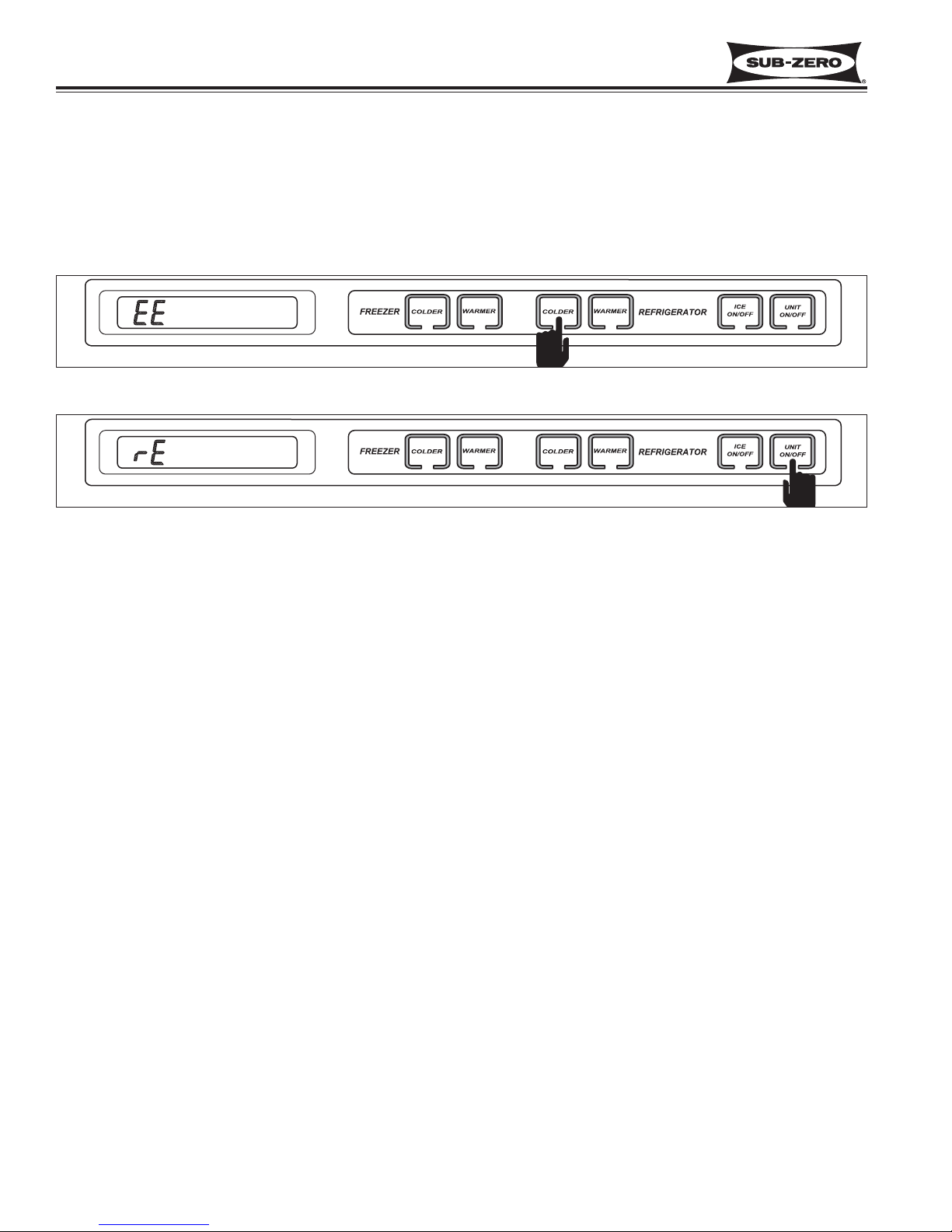
Thermistor Error Indicator
1. While in diagnostic mode, If “EE” is displayed in place of a temperature reading, the thermistor in that location is
either faulty or the electrical line is separated. (In this example, the refrigerator evaporator thermistor is faulty.)
(See Figure 3-35)
2. Press the UNIT ON/OFF key at this time to determine which thermistor is faulty or line separated. ( In this
example, the refrigerator evaporator thermistor is faulty.) (See Figure 3-36)
NOTE: The electronic control will exit diagnostic mode ten (10) seconds after the last key stroke.
SERVICE
ICE
VACUUM
CONDENSER
OFF
SERVICE
ICE
VACUUM
CONDENSER
OFF
Page 31

Electronic Control System
600 Series
(Prior to #1810000)
3-17
#3756270 - Revision B - January, 2006
Figure 3-37. Evaporator Temp, Compartment Air Temp. and Sealed System Pressure vs. Temp. set-point
During Normal Cycle of Operation
Using Temperatures To Troubleshoot Sealed System
To give the 600 Series a true “Sealed System”, the compressor process stub is soldered shut at the factory after the
sealed system is charged. Troubleshooting the sealed system is possible without a process valve because of the
600 Series Electronic Control System. Since the evaporator temperature, compartment air temperature and sealed
system pressure fluctuate harmoniously around the set-point during normal cycle of operation, troubleshooting the
sealed system is accomplished by observing the evaporator temperature reading in Diagnostic Mode.
Following is a chart illustrating how evaporator temperature and compartment air temperature fluctuate harmoniously
around the set-point during normal cycle of operation. Using temperatures to diagnose sealed system problems will
be detailed in the TROUBLESHOOTING GUIDE.
Page 32

Electronic Control System
600 Series
(Prior to #1810000)
3-18
#3756270 - Revision B - January, 2006
Page 33

Sealed System Information
600 Series
(Prior to #1810000)
4-1
#3756270 - Revision B - January, 2006
SECTION 4
SEALED SYSTEM
INFORMATION
Page 34

Sealed System Information
600 Series
(Prior to #1810000)
4-2
#3756270 - Revision B - January, 2006
HFC-134a REFRIGERANT SERVICE INFORMATION
The 600 Series sealed systems contain HFC-134a refrigerant. This section provides general rules for working with
134a, and explains procedures to be followed while servicing the sealed system. This is followed by diagrams which
illustrate sealed system operation, then model-specific refrigerant flow diagrams.
134a refrigerant requires Synthetic Ester oil in the compressor, and does not tolerate contamination from
other refrigerants, moisture, petroleum-based lubricants, silicone lubricants, cleaning compounds, rust
inhibitors, leak detection dyes, or any other type of additive.
General Rules for Working with 134a Refrigerant
• Use equipment dedicated to 134a sealed system service only.
• Use only 134a refrigerant for back-flushing and sweep charging.
• Always replace the filter-drier when servicing the sealed system.
• The filter-drier must be cut from the sealed system. Never un-braze the drier as the heat will drive moisture
back into the sealed system.
• Do not leave sealed system nor replacement compressor open to the atmosphere for more than 10 minutes.
• When the rubber plugs are pulled from the service compressor, a release of pressure should be heard. If no
release of pressure is heard, do not use the compressor.
• Use ONLY virgin 134a refrigerant when recharging the sealed system.
Page 35

Sealed System Information
600 Series
(Prior to #1810000)
4-3
#3756270 - Revision B - January, 2006
600 SERIES SEALED SYSTEM REPAIR PROCEDURES
Service Procedures
a. Capture refrigerant
b. Replace Compressor
c. Replace filter-drier
d. Evacuate or sweep charge system
e. Recharge system with Virgin 134a refrigerant.
NOTE: To check for a non-operating compressor, a hard start kit can be used.
a. Capture refrigerant.
b. Repair leak.
c. Replace filter-drier.
d. Evacuate or sweep charge system.
e. Recharge system with Virgin 134a refrigerant.
a. Capture refrigerant.
b. Repair leak (if at solder joint) or replace part.
c. Back flush high side of sealed system.
d. If all refrigerant has escaped & system is in vacuum, replace compressor
e. Replace filter-drier.
f. Evacuate or sweep charge system.
g. Recharge system with Virgin 134a refrigerant.
a. Capture refrigerant.
b. Repair leak (if at solder joint) or replace part.
c. Back flush high side of sealed system.
d. Replace compressor.
e. Replace filter-drier.
f. Replace heat exchanger if cap tube is clogged.
g. Install a low side drier on suction line.
h. Evacuate or sweep charge sealed system.
i. Recharge with Virgin 134a refrigerant.
a. Capture refrigerant.
b. Locate and remove restriction or locate and replace part.
c. Back flush high side of sealed system.
d. Replace filter-drier.
e. Evacuate or sweep charge system.
f Recharge system with Virgin 134a refrigerant.
a. Capture refrigerant.
b. Replace filter-drier.
c. Evacuate or sweep charge system.
d. Recharge system with Virgin 134a refrigerant.
.
Problem
Non-Operating, Inefficient,
Noisy Compressor
High Side leak
Low Side Leak
Contaminated Sealed System
Examples:
> Burned out compressor
> Excessive moisture from
leak in condensate loop or in
low side
> Plugged capillary tube
Restriction
NOTE: If restriction is due to
sealed system being contaminated, see Contaminated
Sealed System above.
Overcharge
Page 36

Sealed System Information
600 Series
(Prior to #1810000)
4-4
#3756270 - Revision B - January, 2006
Figure 4-1. Compressor
1
3
Figure 4-2. Condenser
2
SEALED SYSTEM OPERATION
The following six diagrams illustrate a basic sealed system. The components are listed in order of refrigerant
flow, with an explanation of their fundamental role as part
of a sealed system. NOTE: These illustrations do not
represent any specific 600 Series sealed system.
Compressor (Figure 4-1)
The compressor creates a high side and low side pressure difference in the sealed system by compressing the
refrigerant gas, thus raising the pressure and temperature. The compressor pushes this high-pressure/highheat gas through the door gasket seat heater loop to prevent sweating (on most units the gas also travels through
drain pan heater tubing to help evaporate water in the
drain pan). The high-pressure/high-heat gas then travels
to the condenser.
Condenser (Figure 4-2)
The high-pressure/high-heat gas travels through the condenser, where the heat is dissipated by cooler air being
drawn over the condenser tubing by the condenser fan.
This changes the gas into a high-pressure/warm liquid
that then enters the high-side filter-drier.
High-Side Filter-Drier (Figure 4-3)
The high-pressure/warm liquid travels through the highside filter-drier, which removes moisture from the refrigerant before it enters the capillary tube.
Compressor
Drain Pan
Heater Tubing
Door Gasket
Seat Heater
Loop
Condenser
High-Side Filter-Drier
Figure 4-3. High-Side Filter-Drier
Page 37

Sealed System Information
600 Series
(Prior to #1810000)
4-5
#3756270 - Revision B - January, 2006
Capillary Tube (Part of Heat Exchanger) (Figure 4-4)
The high-pressure/warm liquid refrigerant travels through
the long skinny capillary tube which is attached to the
suction line. (These two tubes soldered together create
the heat exchanger.) As the high-pressure/warm liquid
refrigerant travels through the capillary tube it gives up
heat to the cool refrigerant gas traveling through the suction line and the pressure drops, so it is a lowpressure/cool liquid before it enters the evaporator.
Evaporator (Figure 4-5)
As the low-pressure/cool liquid refrigerant enters the
evaporator, it vaporizes. This is caused by a dramatic
pressure change which occurs when the refrigerant
enters the larger diameter evaporator tubing from the
smaller diameter capillary tubing. This vapor travels
through the evaporator absorbing heat from the compartment, gradually converting it to a cool gas. This cool gas
then enters the suction line.
Suction Line (& Heat Exchanger) (Figure 4-6)
The cool gas travels through the suction line which is
attached to the capillary tube. (As mentioned earlier,
these two tubes soldered together create the heat
exchanger.) As this cool refrigerant gas travels through
the suction line it absorbs heat from the warm liquid
refrigerant traveling through the capillary tube, making it a
luke warm gas. The lukewarm refrigerant gas returns to
the compressor where the process begins again.
Figure 4-4. Capillary Tube (Part of Heat Exchanger)
4
Figure 4-6. Suction Line (Part of Heat Exchanger)
6
Figure 4-5. Evaporator
5
Capillary Tube
Evaporator Accumulator
Suction Line
Heat
Exchanger
Page 38

Sealed System Information
600 Series
(Prior to #1810000)
4-6
#3756270 - Revision B - January, 2006
Figure 4-7. Models 601R Refrigerant Flow
Figure 4-8. Model 601F Refrigerant Flow
Freezer Compressor
Refrigerator Compressor
Refrigerator Evaporator
Freezer Evaporator
Heater Loop
Drain Pan Heater
Heat Exchanger
Condenser
Condenser
High-Side Filter Drier
High-Side Filter Drier
Heat Exchanger
Page 39

Sealed System Information
600 Series
(Prior to #1810000)
4-7
#3756270 - Revision B - January, 2006
Figure 4-9. Models 611, 650 Refrigerant Flow
Figure 4-10. Models 632, 642, 690 Refrigerant Flow
Freezer Compressor
Freezer Drier
Freezer Heat Exchanger
Drain Pan Heater
Freezer Heater Loop
Freezer Evaporator
Refrigerator Evaporator
Refrigerator Heater Loop
Refrigerator Heat Exchanger
Refrigerator Drier
Refrigerator Compressor
Dual Condenser
Drain Pan Heater
Freezer Heat Exchanger
Freezer Compressor
Freezer Heater Loop
Freezer Evaporator
Freezer Drier
Refrigerator
Drier
Refrigerator Heater Loop
Refrigerator
Evaporator
Dual Condenser
Refrigerator Compressor
Refrigerator
Heat Exchanger
Page 40

Sealed System Information
600 Series
(Prior to #1810000)
4-8
#3756270 - Revision B - January, 2006
Page 41

Air Flow / Fan Blade Spacing
600 Series
(Prior to #1810000)
5-1
#3756270 - Revision B - January, 2006
SECTION 5
AIR FLOW
AND
FAN BLADE SPACING
Page 42

Air Flow / Fan Blade Spacing
600 Series
(Prior to #1810000)
5-2
#3756270 - Revision B - January, 2006
Figure 5-1. Air Flow and Fan Blade Spacing, Models 601R
Figure 5-3. Air Flow and Fan Blade Spacing, Model 601F
FAN BRACKET TO FAN
BLADE HUB SPACING
1-1/4" ± 1/16"
(31.75 mm ± 1.59 mm)
Clamp Down
FAN BRACKET TO FAN
BLADE HUB SPACING
1-1/4" ± 1/16"
(31.75 mm ± 1.59 mm)
Clamp Up
Page 43

Air Flow / Fan Blade Spacing
600 Series
(Prior to #1810000)
5-3
#3756270 - Revision B - January, 2006
Figure 5-4. Air Flow and Fan Blade Spacing, Models 611, 650
Figure 5-6. Air Flow and Fan Blade Spacing, Models 632 and 642
REFRIGERATOR
FAN BRACKET TO FAN
BLADE HUB SPACING
FREEZER
FAN BRACKET TO FAN
BLADE HUB SPACING
29/32" ± 1/16"
(23.02 mm ± 1.59 mm)
Clamp Down
FREEZER
FAN BRACKET TO FAN
BLADE HUB SPACING
7/8" ± 1/16"
(22.23 mm ± 1.59 mm)
1-1/4" ± 1/16"
(31.75 mm ± 1.59 mm)
Clamp Down
REFRIGERATOR
FAN BRACKET TO FAN
BLADE HUB SPACING
(PRIOR TO SERIAL #1810000)
1-1/4"
± 1/16"
Clamp Down
REFRIGERATOR
FAN MOTOR FACE TO FAN
BLADE HUB SPACING
(SERIAL #1810000 - #2064651)
Clamp Back
7/8" ± 1/16"
(22.23 mm ± 1.59 mm)
Clamp Down
Page 44

Air Flow / Fan Blade Spacing
600 Series
(Prior to #1810000)
5-4
#3756270 - Revision B - January, 2006
Figure 5-8. Air Flow and Fan Blade Spacing, Model 690
FREEZER
FAN BRACKET TO FAN
BLADE HUB SPACING
7/8" ± 1/16"
(22.23 mm ± 1.59 mm)
Clamp Left
REFRIGERATOR
FAN BRACKET TO FAN
BLADE HUB SPACING
(PRIOR TO SERIAL #2066436)
1-1/4"
± 1/16"
Clamp Down
REFRIGERATOR
FAN MOTOR FACE TO FAN
BLADE HUB SPACING
(SERIAL #1810000 - #2066436)
Clamp Down
7/8" ± 1/16"
(22.23 mm ± 1.59 mm)
Page 45

Icemaker Information
600 Series
(Prior to #1810000)
6-1
#3756270 - Revision B - January, 2006
SECTION 6
ICEMAKER INFORMATION
Page 46

Icemaker Information
600 Series
(Prior to #1810000)
6-2
#3756270 - Revision B - January, 2006
ICEMAKER SYSTEM INFORMATION
All 600 series units utilize a MidSouth icemaker. An
Icemaker’s operation is not complex, but understanding
its components and its operation cycle is necessary for
a Service Technician to understand in order to make a
proper diagnosis.
TO AVOID ELECTRIC SHOCK, ALWAYS DISCONNECT ELECTRICAL POWER TO UNIT WHEN SERVICING ICEMAKER.
NOTE: The ICE ON/OFF key at the control panel activates the icemaker system. If “ICE” is not displayed on
the LCD, the icemaker system will not function.
NOTE: To allow ice to freeze fully and reduce effects of
low water pressure, the electronic control disables the
icemaker system for 45 minutes after each ice harvest.
NOTE: The ice bucket in models 601F, 611 and 650,
have a tab at the left rear corner that activates a switch
when the ice bucket is in place. The ice bucket in the
models 680 and 690 also activates a switch when in
place. If the ice bucket is not in proper position on any
model, ice production will stop.
NOTE: The icemaker relay on the control board also
controls the fill tube heater and water valve.
ICEMAKER COMPONENTS
Following are descriptions that explain the function of
each icemaker component. The components are diagramed in Figure 6-1 on the next page.
Support - The support is the housing around the electrical components and wire connections. The support is
attached to the ice mold.
Mounting Plate - The drive motor, holding switch,
water valve solenoid switch, timing gear, timing cam
and water fill adjusting screw are attached to the metal
mounting plate. The mounting plate is then attached to
the support.
Drive Motor - 115 volts AC supplied to the drive motor
causes the motor to operate. The motor has a single
output shaft with a small gear. The motor gear
drives/spins the timing gear.
Timing Gear - The timing gear is driven/spun by the
drive motor gear and is attached to the timing cam.
Timing Cam - The timing cam is attached to the timing gear and the ice ejector is inserted into the center of
the timing cam. As the timing cam rotates, high and
low spots on the cam operate the water valve solenoid
switch and the holding switch. The timing cam also
moves the lever arm side to side and rotates the ice
ejector.
Ice Mold - The ice mold is where the eight crescent
shaped ice cubes are formed.
Mold Heater - The mold heater uses 175 watts to
thaw the ice free from the mold.
Ice Ejector - The drive end of the ice ejector is “D”
shaped to fit into the “D” shaped hole in the timing cam.
It has eight blades which rotate and sweep the ice from
the mold cavities during the ejection phase of the cycle.
Ice Stripper - The stripper is attached to the dumping
side of the mold, serving as a decorative side cover and
it also prevents ice from falling back into the mold.
Bearing / Inlet - The bearing / inlet is attached to the
ice mold, opposite the support. Water enters the bearing / inlet and is directed to the ice mold. The
bearing/inlet also supports the ice ejector at the end
opposite the timing cam.
Thermostat - The thermostat is a single-pole, singlethrow, bi-metal switch. At 15°F/± 3°F it closes, starting
the ice ejection phase.
Thermal-Mastic - A substance similar in appearance
to grease that is applied between the thermostat and
the ice mold. Its purpose is to increase thermal conductivity between the mold and the thermostat.
Lever Arm and Shut-off Arm - The lever arm is
moved side to side by two revolutions of the timing
cam. As it moves, it raises and lowers the shut-off arm
and operates the shut-off switch to control the quantity
of ice production. If the shut-off arm comes to rest on
top of the ice in the storage bin during either revolution,
the shut-off switch will remain open, stopping ice production at the end of that revolution.
Water Valve Solenoid Switch - A single-pole, doublethrow type switch that allows electricity to the water
valve solenoid, opening the valve, during the fill cycle.
Holding Switch - A single-pole, double-throw type
switch that assures completion of a revolution once the
icemaker has been energized.
Shut-off Switch - A single-pole, double-throw type
switch that stops ice production when the ice bin is full.
TCO (Thermal Cut Out) - The TCO is thermal protection device in the wire harness that would open in the
event of mechanical failure, thus protecting against over
heating. (The TCO is not shown in diagram.)
Page 47

Icemaker Information
600 Series
(Prior to #1810000)
6-3
#3756270 - Revision B - January, 2006
Figure 6-1. Diagram of Icemaker Components
ICEMAKER OPERATION
The following series of electrical schematics illustrate a
typical icemaker cycle of operation. Below each
schematic is a diagram indicating the approximate location of the ice ejector and ice level arm during the
phase the schematic indicates.
Freeze Phase of Ice Making Cycle (See Figure 6-2)
• The ice mold is filled with water.
• The thermostat is open.
• No icemaker components are energized.
Figure 6-2. The Freeze Phase
(Location of Thermal-Mastic)
Ice Ejector
Holding Switch
Support Plate
Timing Gear
Thermostat
Drive Motor
Cover
Shut-off Switch
Support
Ice Mold and Mold Heater
Ice Level Arm
Lever Arm
Timing Cam
Water Valve Solenoid Switch
Bearing / Inlet
Ice Stripper
SHUT-OFF SWITCH
NO
NC
SOLENOID SWITCH
NCNCNO
WATER
SOLENOID
APPROXIMATE POSITION
OF ICE EJECTOR AND
ICE LEVEL ARM
DURING OPERATION
115 VOLTS
60 CYCLES
THERMOSTAT
C
C
NO
HOLDING SWITCH
WATER
ICE MOLD
TCO
MOLD HEATER
MOTOR
C
ICE BUCKET
Page 48

Icemaker Information
600 Series
(Prior to #1810000)
6-4
#3756270 - Revision B - January, 2006
Start of the First Revolution (See Figure 6-3)
• The water in the ice mold has turned to ice.
• At 15°F/± 3°F the thermostat closes.
• The mold heater is energized through the thermostat.
• The drive motor is started through the thermostat
and “normally closed” terminal of the holding
switch.
• The ice ejector begins to turn and the shut-off arm
begins to rise.
Figure 6-3. Start of First Revolution
Figure 6-4. First Revolution Continued
First Revolution Continued (See Figure 6-4)
• The holding switch is tripped by the timing cam to
“normally open” thus holding power to the motor.
• The mold heater remains energized through the
thermostat.
• The shut-off arm begins to rise.
115 VOLTS
60 CYCLES
TCO
SHUT-OFF SWITCH
NO
NC
SOLENOID SWITCH
NCNCNO
WATER
SOLENOID
APPROXIMATE POSITION
OF ICE EJECTOR AND
ICE LEVEL ARM
DURING OPERATION
C
THERMOSTAT
MOLD HEATER
C
NO
HOLDING SWITCH
C
ICE
ICE MOLD
ICE BUCKET
MOTOR
SHUT-OFF SWITCH
NO
NC
SOLENOID SWITCH
NCNCNO
WATER
SOLENOID
APPROXIMATE POSITION
OF ICE EJECTOR AND
ICE LEVEL ARM
DURING OPERATION
115 VOLTS
60 CYCLES
THERMOSTAT
C
C
NO
HOLDING SWITCH
ICE
ICE MOLD
TCO
MOLD HEATER
MOTOR
C
ICE BUCKET
Page 49

Icemaker Information
600 Series
(Prior to #1810000)
6-5
#3756270 - Revision B - January, 2006
First Revolution Continued (See Figure 6-5)
• The ice ejector reach the ice in the mold.
• The ice releases from the mold as the ejector
blades begin to rotate the cubes out.
• The drive motor remains energized through the
holding switch.
• The mold heater remains energized through the
thermostat.
• As the shut-off arm rises, the shut off switch is
tripped to “normally closed”, and then the shut-off
arm begins to lower.
Figure 6-5. First Revolution Continued
Figure 6-6. First Revolution Continued
First Revolution Continued (See Figure 6-6)
• The ice has released from the mold.
• The motor remains energized through the holding
switch.
• The shut-off arm is lowered and the shut off switch
is tripped to “normally open”.
• The water valve solenoid switch is tripped by the
timing cam, but the solenoid is not energized
because the thermostat is still closed and energizing the mold heater. (Electric current follows the
path of least resistance.)
115 VOLTS
60 CYCLES
TCO
SHUT-OFF SWITCH
NO
NC
SOLENOID SWITCH
NCNCNO
WATER
SOLENOID
APPROXIMATE POSITION
OF ICE EJECTOR AND
ICE LEVEL ARM
DURING OPERATION
C
THERMOSTAT
MOLD HEATER
MOTOR
C
NO
HOLDING SWITCH
C
ICE
ICE MOLD
ICE BUCKET
SHUT-OFF SWITCH
NO
NC
SOLENOID SWITCH
NCNCNO
WATER
SOLENOID
APPROXIMATE POSITION
OF ICE EJECTOR AND
ICE LEVEL ARM
DURING OPERATION
115 VOLTS
60 CYCLES
THERMOSTAT
C
C
NO
HOLDING SWITCH
ICE
ICE MOLD
TCO
MOLD HEATER
MOTOR
C
ICE BUCKET
Page 50

Icemaker Information
600 Series
(Prior to #1810000)
6-6
#3756270 - Revision B - January, 2006
End of First Revolution (See Figure 6-7)
• The water valve solenoid switch is tripped by the
timing cam back to “normally open.”
• The timing cam trips the holding switch to “normally
close,” which ends the first revolution, but the thermostat is still closed, so the motor is again started.
• The mold heater remains energized through the
thermostat.
Figure 6-7. End of First Revolution
Figure 6-8. Start of Second Revolution
Start of Second Revolution:(See Figure 6-8)
• The water valve solenoid switch is tripped by the
timing cam back to “normally open.”
• The timing cam trips the holding switch to “normally
close,” which ends the first revolution, but the thermostat is still closed, so the motor is again started.
• The mold heater remains energized through the
thermostat.
115 VOLTS
60 CYCLES
TCO
SHUT-OFF SWITCH
NO
NC
SOLENOID SWITCH
NCNCNO
WATER
SOLENOID
APPROXIMATE POSITION
OF ICE EJECTOR AND
ICE LEVEL ARM
DURING OPERATION
C
THERMOSTAT
MOLD HEATER
C
NO
HOLDING SWITCH
C
ICE
ICE MOLD
ICE BUCKET
MOTOR
SHUT-OFF SWITCH
NO
NC
SOLENOID SWITCH
NCNCNO
WATER
SOLENOID
APPROXIMATE POSITION
OF ICE EJECTOR AND
ICE LEVEL ARM
DURING OPERATION
115 VOLTS
60 CYCLES
THERMOSTAT
C
C
NO
HOLDING SWITCH
ICE MOLD
TCO
MOLD HEATER
MOTOR
C
ICE
ICE BUCKET
Page 51

Icemaker Information
600 Series
(Prior to #1810000)
6-7
#3756270 - Revision B - January, 2006
Second Revolution Continued (See Figure 6-9)
• The mold heater has warmed the thermostat, so the
thermostat opens, and the mold heater is de-energized.
• If the shut-off arm comes to rest on top of the ice in
the storage bin (as illustrated), so the shut-off
switch will remain in the “normally closed” position.
• The motor remains energized through the holding
switch.
Figure 6-9. Second Revolution Continued
Figure 6-10. Second Revolution Continued
Second Revolution Continued (See Figure 6-10)
• The water valve solenoid switch is tripped by the
timing cam. This time the solenoid is energized
because the thermostat is open. The water solenoid is open for approximately seven seconds, filling the ice mold with water.
• the mold heater is energized through the solenoid
switch and holding switch.
115 VOLTS
60 CYCLES
TCO
SHUT-OFF SWITCH
NO
NC
SOLENOID SWITCH
NCNCNO
WATER
SOLENOID
APPROXIMATE POSITION
OF ICE EJECTOR AND
ICE LEVEL ARM
DURING OPERATION
C
THERMOSTAT
MOLD HEATER
MOTOR
C
NO
HOLDING SWITCH
ICE MOLD
C
ICE BUCKET
ICE
ICE
SHUT-OFF SWITCH
NO
NC
SOLENOID SWITCH
NCNCNO
WATER
SOLENOID
APPROXIMATE POSITION
OF ICE EJECTOR AND
ICE LEVEL ARM
DURING OPERATION
115 VOLTS
60 CYCLES
THERMOSTAT
C
C
NO
HOLDING SWITCH
ICE MOLD
MOLD HEATER
C
ICE BUCKET
ICE
TCO
MOTOR
ICE
Page 52

Icemaker Information
600 Series
(Prior to #1810000)
6-8
#3756270 - Revision B - January, 2006
Figure 6-11. End of Ice Making Cycle
End of Ice making Cycle (See Figure 6-11)
• The water valve solenoid switch is tripped by the
timing cam back to “normally open” ending the
water fill.
• The timing cam trips the holding switch to “normally
close,” which ends the second revolution.
• The thermostat is still open, so it does not start the
drive motor.
• If the shut-off arm has come to rest on top of the
ice in the storage bin (as illustrated), the shut-off
switch remains in the “normally closed” position.
This interrupts power from reaching the thermostat,
until sufficient ice has been removed from the storage bin allowing the shut-off arm to lower.
NOTE: To allow ice to freeze fully and reduce effects of
low water pressure, the electronic control system disables the icemaker system for 45 minutes after each ice
harvest.
Figure 6-12. Stopping Icemaker
MANUALLY STOPPING ICE PRODUCTION
Ice production can be manually stopped four ways:
1. Press the ICE ON/OFF key on the control panel so
that “ICE” is not displayed on the LCD.
2. In model 632 and 642, trip the icemaker switch
above the ice bucket to the OFF position.
3. In models 601F, 611, 650, 680 and 690, remove the
ice bucket so that the icemaker switch at the back
of the freezer is not being depressed. Also, make
sure no food product is coming in contact with the
icemaker switch.
4. In models 611, 650, 680 and 690, lift the ice level
arm up to lock it in the OFF position (See Figure 6-
12).
SHUT-OFF SWITCH
NO
NC
WATER
SOLENOID
APPROXIMATE POSITION
OF ICE EJECTOR AND
ICE LEVEL ARM
DURING OPERATION
C
SOLENOID SWITCH
NCNCNO
C
115 VOLTS
60 CYCLES
THERMOSTAT
NO
HOLDING SWITCH
WATER
ICE MOLD
MOLD HEATER
C
ICE BUCKET
TCO
MOTOR
IC
E
ICE
Arm UP,
Icemaker will Stop
Arm DOWN,
Icemaker will Operate
Page 53

Icemaker Information
600 Series
(Prior to #1810000)
6-9
#3756270 - Revision B - January, 2006
MANUALLY STARTING THE ICEMAKER
NOTE: To allow ice to freeze fully and reduce effects of
low water pressure, the electronic control disables the
icemaker system for 45 minutes after each ice harvest.
To bypass this 45 minute dwell for service purposes,
press the the ICE ON/OFF key or the UNIT ON/OFF
key at the control panel.
Manual Start Procedure
1. Pry the icemaker front cover from the support using
a flat-blade screwdriver or coin.
2. With a flat-blade screwdriver, turn the drive gear
counterclockwise until the holding switch is activated, completing the circuit to the drive motor (this
will be about a 1/8 turn). (See Figure 6-13) The
icemaker will then complete its cycle automatically.
NOTE: If after 1/4 turn the icemaker is not running
on its own, it may be in the 45 minute dwell period
or there is an electrical or mechanical problem.
ADJUSTING ICEMAKER WATER FILL LEVEL
Proper water fill level for a MidSouth icemaker is 100 110 cc’s (3.5 - 3.75 oz). If the fill level is checked and
needs to be adjusted, turn the water fill adjusting screw
clockwise to reduce fill level, or counterclockwise to
increase fill level. One full turn of the screw equals 15
cc’s. (See Figure 6-14)
NOTE: Always check fill level before making any
adjustments of the water fill adjusting screw.
Figure 6-13. Manually Start Icemaker
Figure 6-14. Adjust Water Fill Level
Turn Drive Gear
Counterclockwise
Water Fill Adjusting Screw
1 Full Turn Equals 15 CC's
Turn Clockwise to Reduce Fill
Page 54

Icemaker Information Notes
600 Series
(Prior to #1810000)
6-10
#3756270 - Revision B - January, 2006
Page 55

Component Access / Removal
600 Series
(Prior to #1810000)
7-1
#3756270 - Revision B - January, 2006
SECTION 7
COMPONENT
ACCESS / REMOVAL
Page 56

Component Access / Removal
600 Series
(Prior to #1810000)
7-2
#3756270 - Revision B - January, 2006
COMPONENT ACCESS AND REMOVAL
This section explains how to adjust, access and remove components. If different models have similar procedures,
they are grouped together under the appropriate heading. The models covered in the procedures are listed between
brackets after the heading.
This section is arranged as follows:
.............................................................................................................. Page:
• Primary Parts .................................................................................................................................................... 7-3
• Refrigerator Interior Cosmetic / Mechanical ...................................................................................................... 7-10
• Freezer Interior Cosmetic / Mechanical / Electrical ............................................................................................ 7-15
• Lower Compressor Area / Mechanical / Electrical .............................................................................................. 7-32
• Upper Compressor Area / Mechanical / Electrical .............................................................................................. 7-33
• Water Valve ........................................................................................................................................................ 7-35
• Sealed System .................................................................................................................................................. 7-36
An attempt has been made to arrange these procedures in such a way as to simulate which components would
need to be removed first in order to gain access to other components. When following a component removal procedure, it may be necessary to reference another component removal procedure earlier in this section.
NOTE: Before continuing, please take note of the WARNINGS and CAUTIONS below.
• IF IT IS NECESSARY TO REMOVE A UNIT FROM ITS INSTALLATION, REMEMBER THAT THE UNIT
COULD TIP FORWARD WHEN PULLED FORWARD BEYOND THE ANTI-TIP COMPONENTS, RESULTING
IN SERIOUS INJURY OR DEATH. PULLING A UNIT FROM ITS INSTALLATION SHOULD ONLY BE PERFORMED BY AN AUTHORIZED SERVICE TECHNICIAN OR INSTALLER.
• TO AVOID ELECTRIC SHOCK, POWER TO THE UNIT MUST BE DISCONNECTED WHENEVER ACCESS-
ING AND/OR REMOVING COMPONENTS POWERED BY ELECTRICITY OR COMPONENTS NEAR OTHER
ELECTRICAL COMPONENTS. IF THE UNIT IS PLUGGED IN, BUT HAS NOT BEEN SWITCHED ON BY
PRESSING THE UNIT ON/OFF KEY, 115 VOLTS AC IS STILL PRESENT AT THE CONTROL BOARD.
• IF REMOVING A DOOR OR DRAWER FROM A UNIT, REMEMBER THAT DOORS AND DRAWERS ARE
HEAVY. IF THEY WERE TO FALL, THEY COULD CAUSE SERIOUS PERSONAL INJURY.
• If removing or disconnecting door closer assemblies, remember they are spring loaded and could recoil
quickly when released.
• If working in the compressor area, remember that compressor and tubing may be hot.
• If working on or around an evaporator or condenser, remember that evaporator and condenser fins are
sharp.
Page 57

Component Access / Removal
PRIMARY PARTS
This section explains how to remove and adjust the primary 600 Series parts (upper light diffuser, door
shelves, cabinet shelves, etc.). In most cases, removal
of these parts is necessary in order to gain access to
the more functional components during a service call.
When possible, units with similar primary part removal
procedures are grouped together under the appropriate
heading. The units covered will be listed between
brackets after the heading.
Upper Light Diffuser (All models)
The side frames of the light diffuser have four inverted
“T” shaped slots (two each side) which slide up over
pegs protruding from the side walls. For safety purposes, retaining clips by the rear slots secure the light diffuser to the rear studs. (See Figure 7-1)
To remove the light diffuser, slide a finger over the top
of the retaining clips and rotate down. With the clips
open, lift diffuser up and slide it towards the rear of the
unit until the center of the “T” slots line up with the
pegs. Then lower the light diffuser and remove from
unit. (See Figure 7-2)
Light Bulb (All Models)
The light diffuser will need to be removed to access the
light bulbs. Screw bulb counter clockwise to remove,
clockwise to install.
Door Shelf & Dairy Compartment Assemblies
(All Models)
Removal and adjustment of door shelves and dairy
compartment assemblies is achieved by sliding the
grooves in the end caps over the molded retaining ribs
of the door liner. Lift up and out to remove, push in and
down to install. (See Figure 7-3)
Figure 7-3. Door Shelf Removal
Figure 7-1. Slots & Retaining Clips
Figure 7-2. Light Diffuser Removal
Retaining Clips
“T” Slots
600 Series
(Prior to #1810000)
7-3
#3756270 - Revision B - January, 2006
ELECTRIC SHOCK HAZARD. IF BULB SHOULD
SEPARATE FROM BASE. DISCONNECT POWER
TO UNIT BEFORE ATTEMPTING TO REMOVE BASE
FROM SOCKET.
Light bulbs are hot and could cause minor personal injury.
Page 58

Component Access / Removal
600 Series
(Prior to #1810000)
7-4
#3756270 - Revision B - January, 2006
Refrigerator & Freezer Compartment Shelves
(All Models)
Remove and adjust shelf by tilting up at front while lifting the back up and out of the shelf ladders. (See
Figure 7-4)
To reinstall, tilt front of shelf up and align hooks at back
corners with slots in shelf ladders, then insert hooks
into slots and lower front of shelf.
Utility Basket
(Models 601R, 611, 632, 642, 650, 690)
Remove the utility basket from under the shelf assembly by pulling the basket out and lifting at the front.
Reverse to reinstall. (See Figure 7-5)
Crisper Glass Shelf
(Models 601R, 611, 632, 642, 650, 690)
Remove crisper glass shelf assembly by opening top
drawer and lifting assembly off of crisper glass supports.
Large High Humidity Drawer
(Models 601R, 611, 632, 642, 650, 690)
Remove high humidity drawer assembly by pulling open
until drawer stops, then lift front of drawer while pulling
out. (See Figure 7-6)
Figure 7-6. High Humidity Drawer Removal
Figure 7-4. Shelf Removal
Figure 7-5. Utility Basket Removal
Shelf Ladders
Page 59

Component Access / Removal
600 Series
(Prior to #1810000)
7-5
#3756270 - Revision B - January, 2006
Humidity Drawer Carriage Assembly (Models 601R,
611, 632, 642, 650, 690)
After removing the crisper glass shelf and high humidity
drawer, lift carriage assembly up at front to disengage
from the tab on slide assemblies. Then pull carriage
assembly forward to disengage from hooks at rear of
slide assemblies. (See Figure 7-7)
NOTE: The silicone seal between carriage and slide
arm may need to be broken with a knife.
Small Storage Drawer
(Models 632, 642, 690)
Remove the small storage drawer assemblies by pulling
open until drawer stops (1). Raise front of drawer (2)
while pulling out further to bypass stop (3), then drop
front of drawer down while lifting rear drawer rollers out
of the roller/slide assemblies (4). (See Figure 7-8)
Freezer Basket
(Models 601F, 632, 642, 690)
Remove freezer baskets by pulling open until basket
stops, then lift up at the front and pull out. (See Figure
7-9)
Figure 7-9. Freezer Basket Removal
Figure 7-7. Drawer Carriage Assembly Removal
Figure 7-8. Small Storage Drawer Removal
1
2
3
4
Page 60

Component Access / Removal
600 Series
(Prior to #1810000)
7-6
#3756270 - Revision B - January, 2006
Freezer Glass Shelf (Model 601F)
The glass shelf is secured to the side walls by screws
through the side frames. To remove the freezer glass
shelf, the two top freezer baskets will first need to be
removed. Now, from underneath the glass shelf,
remove the two front mounting screws, and loosen the
two rear screws. (The rear screws fit into slots, so they
do not need to be fully removed.) Then pull shelf forward slightly and lift up and out. (See Figure 7-10)
NOTE: When reinstalling freezer glass shelf, be sure
that the flange at top of freezer basket center slide support sets into the channel in the freezer glass shelf
front. (See Figure 7-10)
Ice Bucket (Model 601F)
Remove ice bucket by lifting out of top right freezer basket.
Ice Bucket (Model 611 and 650)
Remove ice bucket by lifting out of left rear corner of
upper freezer basket.
Ice Bucket Assembly
(Model 632 and 642)
Remove ice bucket assembly by pulling ice bucket
open until it stops, then lift up and pull forward. (See
Figure 7-11) When reinstalling, the ice bucket carriage
assembly must be pulled fully forward, then hook rear
flange of ice bucket over carriage assembly and push
ice bucket assembly in.
Juice Can Rack Removal (Model 690)
Remove juice can rack by lifting up and pulling out.
(See Figure 7-12)
Figure 7-12. Model 690 Juice Can Rack Removal
Figure 7-11. Model 632, 642 Ice Bucket Removal
2
Pull out
2
Pull open
1
Lift up
1
Lift up
Figure 7-10. Model 601F Freezer Glass Shelf Removal
Rear Slots
Flange
Page 61

Component Access / Removal
600 Series
(Prior to #1810000)
7-7
#3756270 - Revision B - January, 2006
Ice Bucket Assembly (Model 690)
To remove the ice bucket assembly, the juice can rack
must first be removed. Then lift ice bucket assembly up
and pull out. (See Figure 7-13)
NOTE: When reinstalling ice bucket, the drive yoke of
the auger motor must engage ice bucket auger correctly so that ice bucket assembly can be fully installed.
Standard Louvered Grille
(Models 601R/F, 601R/O, 601F/F, 601F/O)
The standard louvered grille on models 601R & 601F
consists of an upper grille section and a lower grille
section. To remove the lower grille section, extract the
screws at the bottom left and right corners. Then, tilt
the bottom of lower grille section out and up to release
it from the upper grille section. (See Figure 7-14)
To remove the upper grille section, open cabinet door
and extract the screws at the top left and right corners.
Pull upper grille section forward slightly and disconnect
fan and light switches electrical leads. (See Figure 7-
14)
Stainless Steel Grille
(Models 601R/S, 601F/S)
The stainless steel grille on models 601R/S & 601F/S
consists of an upper grille section and a lower grille
section. The lower grille section is secured at the bottom by a “catch and strike” retention system. To
remove the lower grille section, grasp bottom of grille
and tilt out and up to release it from the catch and strike
at the bottom. Continue to tilt out and up to release it
from the upper grille section. (See Figure 7-15)
To remove the upper grille section, open cabinet door
and extract the screws at the top left and right corners.
Pull upper grille section forward slightly and disconnect
fan and light switches electrical leads. (See Figure 7-
15)
Figure 7-15. Model 601R, 601F Stainless Steel Grille
Figure 7-14. Model 601R, 601F Standard Louvered
Grille
Upper Grille
Section
Upper Grille
Section
Catch and
strike behind
grille
Screw
Tilt out and up
Figure 7-13. Model 690 Ice Bucket Removal
2
Pull open
1
Lift up
THE UPPER GRILLE SECTION HOLDS THE FAN
AND LIGHT SWITCH. TO AVOID ELECTRICAL
SHOCK, DISCONNECT POWER TO UNIT BEFORE
ATTEMPTING TO REMOVE UPPER GRILLE SECTION.
Page 62

Component Access / Removal
600 Series
(Prior to #1810000)
7-8
#3756270 - Revision B - January, 2006
Drain Pan
(Models 601R, 601F)
To access the drain pan, the kickplate and lower grille
section must first be removed. Then push the drain pan
up and out from underneath. (See Figure 7-16)
Louvered Grille and Stainless Steel Grille Assembly
(Models 611/F, 611/S, 632/F, 632/S, 642/F, 642/S,
650/F, 650/S, 690/F, 690/S)
Removal procedures for the standard louvered grille
and stainless steel grille are the same. To remove the
louvered grille assembly, open unit door(s) and extract
the grille screws which pass up through the top mainframe extrusion into brackets at bottom rear of grille
assembly. Now, tilt the top of grille forward and release
the grille springs from the grille hooks at the back side
of the grille. Then lift grille assembly off. (See Figure
7-17)
Panel Grille Assembly
(Models 611/O, 632/O, 642/O, 650/O)
The panel grille assembly consists of an outer and an
inner grille frame. The outer grille frame attaches to the
unit, while the inner grille frame(which accepts a decorative panel) is easily removable for condenser cleaning
purposes. There are pegs on the back side of the inner
grille frame which fit in key-hole slots in the outer grille
frame. To remove the inner grille frame, lift assembly
up (1) and pull out of key-hole slots at the bottom (2).
Then, pull down and out of key-hole slots at the top (3).
(See Figure 7-18)
To remove the outer grille frame, remove the inner grille
frame first. Now, opening unit door(s) and extract the
grille screws which pass up through the top mainframe
extrusion into bottom extrusion of outer grille frame.
Now, extract the screws at the top front of outer grille
frame and lift frame off.
Figure 7-18. Inner Grille Frame Removal
Figure 7-17. Grille Removal
Grille Spring
Grille Screws
Inner Grille
Frame
3
2
1
2
1
3
Figure 7-16. Model 601R, 601F Drain Pan Removal
Drain Pan
When reinstalling drain pan be sure drain pan is
secure and level. Failure to reinstall drain pan
properly could result in drain pan overflowing.
Page 63

Component Access / Removal
600 Series
(Prior to #1810000)
7-9
#3756270 - Revision B - January, 2006
Kickplate Removal
To remove the kickplate, extract the retaining screws
near each upper corner, then pull the kickplate forward.
(See Figure 7-19)
Drain Pan Access and Removal
(Models 611, 632, 642, 650, 690)
To access the drain pan, the kickplate must first be
removed. Now push the front of the drain pan back and
down. (This flexes the drain pan slightly, releasing the
top flange from the tab in the kickplate support.) Then,
pull the drain pan forward. (See Figure 7-20)
When reinstalling, the tapered end of drain pan must be
inserted on top of the drain pan holder at rear. Then
push the front of the drain pan up until the top front
flange engages the tab in the kickplate support. Also,
make sure the drain hoses are over the drain pan, and
the foam air seals which direct air over drain pan are in
position and in good shape. (See Figure 7-20)
Figure 7-20. Model 611, 632, 642, 650, 690 Drain
Pan Removal
Drain Pan
Foam Air Seal
Drain Pan Support
Figure 7-19. Kickplate Removal
When reinstalling drain pan be sure drain pan is
secure and level. Failure to reinstall drain pan
properly could result in drain pan overflowing.
Page 64

Figure 7-21. Upper Refrigerator Compartment Area
Figure 7-22. Control Board Removal
Control Board
Panel Mounting Screws
Control Panel
Evaporator Fan Shroud
Control Board
Ta b
Ta b
Ribbon Cable
Forward Tabs
Component Access / Removal
600 Series
(Prior to #1810000)
7-10
#3756270 - Revision B - January, 2006
REFRIGERATOR MECHANICAL AND ELECTRICAL COMPONENTS
Control Board (Models 601R, 611, 632, 642, 650)
NOTE: Model 690 control board access and removal is
covered later in this section.
The control board is held in position by two sets of tabs
behind the left side of the control panel. The two forward tabs position the LCD in the control panel window,
while the other two tabs secure the middle of the control
board. The control board is then shielded by a control
enclosure, and concealed by the light diffuser.
To access and remove the control board, the light diffuser must first be removed. Now extract the screws
securing the control enclosure to the ceiling of the compartment. Then, lower the back of the enclosure while
pulling it toward the rear of the unit. Disconnect all
electrical leads attached to the control board, including
the membrane switch ribbon cable. Expand the two
tabs at the middle of the control board outward while
pulling the back of the board down slightly. Then,
expand the two forward tabs outward that hold the LCD
in position, and pull the control board down and toward
the rear of the unit. (See Figures 7-21 & 7-22)
Control Panel (Models 601R, 611, 632, 642, 650)
NOTE: Model 690 vertical control panel access and
removal is covered later in this section.
The control panel, which houses the membrane switch,
is secured to the ceiling of the compartment by two
rows of screws. The front row of screws are through
keyhole slots in the assembly. To access and remove
the control panel, the light diffuser and control enclosure must be removed first.
NOTE: It is recommended, but not necessary, to
remove the control board in order to remove the control
panel. If leaving the control board secured to the control panel, all electrical leads attached to the control
board must be disconnected.
Now, extract the back row of screws at the back of the
control panel. Push the panel back to release it from
the front row of screws, then lower the panel down and
pull out. (See Figure 7-21)
Page 65

Component Access / Removal
Refrigerator Evaporator Cover (Models 601R, 611,
632, 642, 650)
The bottom of the refrigerator evaporator cover is
secured by slots in the side flanges fitting over pegs at
the bottom of each shelf ladder. At the top, screws hold
the evaporator cover to the evaporator fan shroud. To
access and remove the evaporator cover, the light diffuser must first be removed. Then extract the screws at
the top of the evaporator cover, tilt it forward and lift out.
(See Figure 7-23)
Refrigerator Evaporator Cover (Model 690)
The bottom of the refrigerator evaporator cover is
secured by slots in the side flanges fitting over pegs at
the bottom of each shelf ladder. Below the water reservoir area is a screw holding the evaporator cover to a
bracket at the back wall. And, at the top, screws hold
the evaporator cover to the evaporator fan shroud.
(See Figure 7-23)
To access and remove the evaporator cover, the light
diffuser must first be removed. Now extract the screws
at the top of the evaporator cover and below the water
reservoir area. Then, tilt the evaporator cover forward
and lift out.
Refrigerator Evaporator Fan Shroud (Models 601R,
611, 632, 642, 650, 690)
To access the evaporator fan shroud assembly, the light
diffuser and evaporator cover will need to be removed
first. Now extract the mounting screws which secure
the fan shroud assembly to the ceiling of the refrigerator
compartment. Then lower the assembly and disconnect
the wiring for the lights from the wire harness. (See
Figure 7-21 and 7-24)
Refrigerator Evaporator Fan Assembly (Models
601R, 611, 632, 642, 650, 690)
To access the evaporator fan assembly, the light diffuser, evaporator cover, and evaporator fan shroud
assembly will need to be removed. Now, disconnect
the fan motor wire leads from the wire harness, and
extract the mounting screws which secure the fan
assembly to the ceiling. (See Figure 7-25)
Figure 7-23. Evaporator Cover Removal
Screws
Slots & Pegs
(not shown)
Screw
600 Series
(Prior to #1810000)
7-11
#3756270 - Revision B - January, 2006
Figure 7-24. Fan Shroud Assembly Removal
Figure 7-25. Refrigerator Evaporator Fan Removal
Mounting Screws
Wire Connection
Page 66

Component Access / Removal
600 Series
(Prior to #1810000)
7-12
#3756270 - Revision B - January, 2006
Figure 7-27. Water Tank Cover Removal
Water Reservoir
Tank Cover
Retaining Screws
Refrigerator Compartment Thermistor
(Models 601R, 611, 632, 642, 650, 690)
The refrigerator compartment thermistor is located
behind the evaporator cover, and attached to the wall
just above the evaporator. To access and remove the
refrigerator compartment thermistor, the light diffuser
and evaporator cover must be removed first. Now disconnect the thermistor wire leads from the wire harness, and extract the screw which secures the thermistor to the rear wall. (See Figure 7-26)
Refrigerator Evaporator Thermistor
(Models 601R, 611, 632, 642, 650, 690)
NOTE: Evaporator fins are sharp and could cause
minor personal injury.
The refrigerator evaporator thermistor is attached to the
center of the right evaporator bracket. To access and
remove the refrigerator evaporator thermistor, the light
diffuser and evaporator cover must be removed first.
Now disconnect the thermistor wire leads from the wire
harness, and extract the screw which secures the thermistor to the right evaporator bracket. (See Figure 7-
26)
Water Reservoir Tank Cover (Model 690)
To remove the water reservoir tank cover, the light diffuser and upper front panel must be removed first.
NOTE: The procedure for removing the upper front
panel in a model 690 is the same as removing an upper
control panel.
Now, extract the retaining screw at the bottom rear of
vertical control panel, and the retaining screw at top
center of the tank cover. Then, grasp the bottom of the
reservoir tank cover and slide it backwards to depress
the mounting springs. Swing the front edge out and
pull forward. (See Figure 7-27)
Figure 7-26. Refrigerator Thermistors
Compartment Thermistor
Evaporator
Thermistor
Refrigerator Evaporator
Page 67

Component Access / Removal
600 Series
(Prior to #1810000)
7-13
#3756270 - Revision B - January, 2006
Control Board (Model 690)
The control board is held in position by two sets of tabs
behind the control panel. The two forward tabs position
the LCD in the control panel window, while the other
two tabs secure the middle of the control board. The
control board is then shielded by a control enclosure,
and concealed by the water reservoir tank cover.
To access and remove the control board, the light diffuser, upper front panel and water reservoir tank cover
must first be removed. Now extract the screws securing the control enclosure to the mullion wall of the compartment. Then, pull the back of the enclosure out and
toward the rear of the unit. Disconnect all electrical
leads attached to the control board, including the membrane switch ribbon cable. Expand the two tabs at the
middle of the control board outward while pulling the
back of the board out slightly. Then, expand the two
forward tabs outward that hold the LCD in position, and
pull the control board out and toward the rear of the
unit. (See Figure 7-28)
Vertical Control Panel (Model 690)
The control panel, which houses the membrane switch,
is secured to the mullion wall by screws and a sheet
metal retainer. To access and remove the control
panel, the light diffuser, upper front panel, water reservoir tank cover and control enclosure must be removed
first.
NOTE: It is recommended, but not necessary, to
remove the control board in order to remove the control
panel. If leaving the control board secured to the control panel, all electrical leads attached to the control
board must be disconnected.
Now, extract the screws at the back of the control panel
and pull panel forward from sheet metal retainer. (See
Figure 7-29)
Figure 7-28. Control Board Removal
Ta b
Ta b
Ta b
Control
Board
Vertical
Control Panel
Ribbon Cable
Figure 7-29. Vertical Control Panel Removal
Screw
Screw
Retainer
Vertical
Control Panel
Page 68

Component Access / Removal
600 Series
(Prior to #1810000)
7-14
#3756270 - Revision B - January, 2006
Figure 7-30. Water Tank & Ice Chute Removal
Water Reservoir Tank (Model 690)
To access and remove the water reservoir tank, the
light diffuser, upper front panel and water reservoir tank
cover will need to be removed first. Now disconnect
the compression fittings at the inlet and outlet of the
water reservoir tank. Then remove the mounting
screws and lift out. (See Figure 7-30)
NOTE: After reinstalling a water reservoir tank, the
WATER button at the door dispenser must be
depressed for approximately two minutes to refill the
tank.
Ice Chute Components (Model 690)
To access the ice chute, the light diffuser, upper front
panel and water reservoir tank cover will need to be
removed. The ice chute cover is removed by depressing the tabs at the sides and pulling the cover out and
back. (See Figure 7-30)
NOTE: The ice chute door in the mullion wall is accessible at this point.
To remove the ice chute/water nozzle assembly, disconnect the water line from the water nozzle, then extract
the mounting screws and pull the assembly out and
back. (See Figure 7-30)
Water
Reservoir
Tank
Ice Chute
Tabs
Water in reservoir tank will drain from lower inlet
when compression fitting is removed. A container
with a volume of at least 1/2 gallon should be used
to catch the draining water.
Page 69

Component Access / Removal
600 Series
(Prior to #1810000)
7-15
#3756270 - Revision B - January, 2006
FREEZER MECHANICAL AND ELECTRICAL
COMPONENT REMOVAL
Control Board (Model 601F)
The control board is held in position by two sets of tabs
behind the left side of the control panel. The two forward tabs position the LCD in the control panel window,
while the other two tabs secure the middle of the control board. The control board is then shielded by a control enclosure, and concealed by the light diffuser.
To access and remove the control board, the light diffuser must first be removed. Now extract the screws
securing the control enclosure to the ceiling of the compartment. Then, lower the back of the enclosure while
pulling it toward the rear of the unit. Disconnect all
electrical leads attached to the control board, including
the membrane switch wire harness. Expand the two
tabs at the middle of the control board outward while
pulling the back of the board down slightly. Then,
expand the two forward tabs outward that hold the LCD
in position, and pull the control board down and toward
the rear of the unit. (See Figures 7-31 & 7-32)
Control Panel (Model 601F)
The control panel, which houses the membrane switch,
is secured to the ceiling of the compartment by two
rows of screws. The front row of screws are through
keyhole slots in the assembly. To access and remove
the control panel, the light diffuser and control enclosure must be removed first.
NOTE: It is recommended, but not necessary, to
remove the control board in order to remove the control
panel. If leaving the control board secured to the control panel, all electrical leads attached to the control
board must be disconnected. (See Figure 7-32)
Now, extract the screws at the back of the control
panel. Then, loosen the screws in the keyhole slots
toward the front of the control panel. Push the panel
back, then lower the panel down and out. (See Figure
7-31)
Figure 7-31. Upper Freezer Compartment Area
Figure 7-32. Control Board Removal
Control Board
Panel Mounting Screws
Control Panel
Evaporator Fan Shroud
Control Board
Ta b
Ta b
Ribbon Cable
Forward Tabs
When re-connecting membrane switch ribbon
cable to control board, be sure label on ribbon
cable terminal housing is oriented toward arrow on
control board connection. Also, care should be
taken to not kink the ribbon cable.
DISCONNECT POWER TO UNIT TO AVOID ELECTRICAL SHOCK BEFORE ATTEMPTING TO
REMOVE CONTROL BOARD.
Page 70

Component Access / Removal
600 Series
(Prior to #1810000)
7-16
#3756270 - Revision B - January, 2006
Freezer Evaporator Cover (Model 601F)
The bottom of the freezer evaporator cover is secured
by slots in the side flanges fitting over pegs at the bottom of each shelf ladder. At the top, screws hold the
evaporator cover to the evaporator fan shroud. To
access and remove the evaporator cover, the light diffuser and freezer glass shelf must first be removed.
Then extract the screws at the top of the evaporator
cover, tilt it forward and lift out. (See Figure 7-33)
Freezer Evaporator Fan Shroud Assembly (Model
601F)
To access and remove the evaporator fan shroud
assembly, the light diffuser and evaporator cover will
need to be removed first. Now extract the mounting
screws which secure the fan shroud assembly to the
ceiling of the refrigerator compartment. Then lower the
assembly and disconnect the wiring for the lights from
the wire harness. (See Figure 7-34)
Freezer Evaporator Fan Assembly Access and
Removal (Model 601F)
To access the evaporator fan assembly, the light diffuser, evaporator cover, and evaporator fan shroud
assembly will need to be removed. Now, disconnect
the fan motor wire leads from the wire harness, and
extract the mounting screws which secure the fan
assembly to the ceiling. (See Figure 7-35)
Figure 7-33. Evaporator Cover Removal
Figure 7-34. Model 601F Fan Shroud Removal
Figure 7-35. Model 601F Evaporator Fan Removal
Screws
Slots & Pegs
(not shown)
Mounting Screws (4)
Wire Connection
Page 71

Component Access / Removal
600 Series
(Prior to #1810000)
7-17
#3756270 - Revision B - January, 2006
Freezer Evaporator Thermistor (Model 601F)
The freezer evaporator thermistor is attached to the left
evaporator bracket. To access and remove the freezer
evaporator thermistor, the light diffuser and evaporator
cover must be removed first. Now disconnect the thermistor wire leads from the wire harness, and extract the
screw which secures the thermistor to the left evaporator bracket. (See Figure 7-36)
Defrost Terminator (Model 601F)
The defrost terminator is attached to the top center
pass of the evaporator. To access and remove the
defrost terminator, the light diffuser and evaporator
cover must be removed first. Now disconnect the
defrost terminator wire leads from the wire harness, and
pull the terminator off of the evaporator tubing. (See
Figure 7-36)
Defrost Heater (Model 601F)
To access and remove the freezer evaporator defrost
heater, the light diffuser and evaporator cover will need
to be removed first. The heater clips which secure the
heater to the evaporator now need to be removed.
Dislodge the heater clips by pulling the tab of the clip
down and out. Then disconnect the heater wires from
the wire harness, and gently pull the heater from the
fins of the evaporator. (Figure 7-36)
Figure 7-36. Model 601F Evaporator Area
Thermistor
Defrost Terminator
Evaporator
Evaporator heater
Evaporator fins are sharp and could cause minor
personal injury.
Page 72

Component Access / Removal
600 Series
(Prior to #1810000)
7-18
#3756270 - Revision B - January, 2006
Freezer Compartment Thermistor (Model 601F)
The freezer compartment thermistor is attached to the
bottom center of the drain trough enclosure, just above
the top center freezer basket slide. (See Figure 7-37)
The thermistor wire leads attach to the wire harness
behind the drain trough enclosure. To access and
remove freezer compartment thermistor, the drain
trough enclosure must first be detached from the back
wall. Now, disconnect the thermistor wire leads from
the wire harness. Then extract the screw which
secures the thermistor to the drain trough enclosure.
Icemaker Assembly (Model 601F)
The icemaker assembly is located behind the top right
freezer basket, just below the glass shelf. (See Figure
7-37) To access and remove the icemaker assembly,
remove the top right freezer basket which contains the
ice bucket first. The ice level mechanism now needs to
be detached from the icemaker. This is done by sliding
the connecting rod to the right, off of the icemaker shutoff arm, allowing the ice level arm to drop out of the
way. Now remove the mounting screw at the bottom
left of the icemaker which secures the icemaker bracket
to the drain trough enclosure. Extract the two mounting
screws at the top rear, above the icemaker mold; pull
the icemaker assembly forward and disconnect the
electrical leads from the icemaker. ( See Figure 7-38)
Fill Tube Heater (Model 601F)
The icemaker fill tube and fill tube heater are located at
top right of icemaker, just below the freezer glass shelf
and above the drain trough enclosure. (See Figure 7-
38) The icemaker fill tube heater plugs into the wire
harness behind the drain trough enclosure.
NOTE: To access the fill tube heater it is recommended, but not necessary, to remove the freezer glass
shelf.
To remove the fill tube heater, first remove the drain
trough enclosure. Disconnect the fill tube heater from
the wire harness and pull the fill tube and heater out as
one. Then, cut the cable tie which holds the heater to
the fill tube.
Drain Trough Enclosure (Model 601F)
The drain trough enclosure is located at the rear of the
compartment, just below the freezer glass shelf. (See
Figure 7-37)
NOTE: To access the drain trough enclosure it is recommended, but not necessary, to remove the freezer
glass shelf.
To remove the drain trough enclosure, extract the
mounting screw at the top of each corner and the
mounting screws along the bottom. Then, pull enclosure forward.
NOTE: It is not necessary to remove the icemaker nor
freezer compartment thermistor in order to detach the
drain trough enclosure from the rear wall. But, the icemaker wire harness and thermistor electrical leads
behind the drain trough enclosure will need to be disconnected in order to remove enclosure completely.
Figure 7-38. Model 601F Icemaker Area
Connecting Rod
Screws
Ice Level Arm
Drain
Tube
Heater
Fill Tube Heater
Drain Trough Enclosure
Compartment Thermistor
Freezer Glass Shelf
Icemaker
Figure 7-37. Model 601F Icemaker/Drain Trough Area
Page 73

Component Access / Removal
600 Series
(Prior to #1810000)
7-19
#3756270 - Revision B - January, 2006
Drain Tube Heater (Model 601F)
The braided wire drain tube heater is connected to the
wire harness behind the drain trough enclosure. To
access and remove the drain tube heater, the drain
trough enclosure will need to be removed first. Now,
disconnect the heater from the wire harness, remove
the clamp which holds the heater in place, and pull the
drain tube heater from the drain tube. (See Figures 738 & 7-39)
NOTE: When replacing the drain tube heater, it is necessary to insert it a minimum of 3" into the drain tube.
Drain Trough Heater (Model 601F)
The drain trough heater consists of a braided wire
heater between two strips of aluminum foil, one of
which has adhesive on the outside. This adhesive side
holds the drain trough heater to the bottom of the drain
trough. To access and remove the drain trough heater,
the drain trough enclosure will need to be removed first.
Now, disconnect the heater wires from the wire harness, and peel the heater from the bottom of the drain
trough. (See Figure 7-39)
NOTE: When replacing the drain trough heater, the bottom of the drain trough must be dry in order for the
heater to stick properly.
Figure 7-39. Model 601F Freezer Drain Area
Drain Trough Heater
Drain Trough
Drain Tube
Page 74

Component Access / Removal
600 Series
(Prior to #1810000)
7-20
#3756270 - Revision B - January, 2006
Freezer Light Bulb Access
(Models 611, 650)
There is no light diffuser in the freezer of these models.
The light bulbs are located directly behind the top
breaker strip. (See Figure 7-40)
Icemaker Assembly Removal (Models 611, 650)
To remove the icemaker, extract the mounting screw at
the bottom of the icemaker which secures the icemaker
bracket to the left side wall. Then extract the two
mounting screws at the top, above the icemaker mold.
Pull the icemaker assembly down, disconnect the electrical leads from the the icemaker, and remove the ice
level arm from the bracket. (See Figure 7-41)
Icemaker Fill Tube Heater (Models 611, 650)
The icemaker fill tube and fill tube heater are located at
the top left rear corner of the freezer compartment, just
above the switch enclosure. The fill tube heater plugs
into the right side of the switch enclosure. To access
the fill tube heater, first remove the icemaker. Then,
disconnect the fill tube heater from the switch enclosure
and pull the fill tube and heater out as one. (See
Figure 7-42)
Figure 7-40. Model 611, 650 Freezer Lighting
Figure 7-41. Models 611, 650 Icemaker
Figure 7-42. Model 611, 650 Icemaker Fill
Tube/Heater & Switch Enclosure
Fill Tube Heater
Mounting Screws
Evaporator Cover
Breaker Strip
Light Bulbs
Air Duct
Switch Enclosure
Light bulbs are hot and could cause minor personal injury.
ELECTRIC SHOCK HAZARD. IF BULB SHOULD
SEPARATE FROM BASE, DISCONNECT POWER
TO UNIT BEFORE ATTEMPTING TO REMOVE BASE
FROM SOCKET.
Page 75

Component Access / Removal
600 Series
(Prior to #1810000)
7-21
#3756270 - Revision B - January, 2006
Freezer Light, Fan and Icemaker Switches
(Models 611, 650)
The freezer light, fan and icemaker switches are located inside the switch enclosure at the top left rear corner
of the freezer compartment. (See Figure 7-41.) To
access and remove a freezer light, fan and/or icemaker
switch, the icemaker should first be removed. Now
extract the screws securing the switch enclosure to the
top left rear corner of the freezer compartment. Then,
lower the enclosure and disconnect the wire leads from
the switch being removed. Depress the tabs on the
side of the switch and push the switch out of the enclosure. (See Figures 7-42 and 7-43)
Freezer Compartment Thermistor (Models 611, 650)
The freezer compartment thermistor is located inside
the switch enclosure at the top left rear corner of the
freezer compartment. (See Figure 7-41) To access
and remove the freezer compartment thermistor, the
icemaker should first be removed. Now extract the
screws securing the switch enclosure to the top left rear
corner of the freezer compartment. Then, lower the
enclosure and disconnect the thermistor wire leads
from the wire harness, and extract the screw which
secures the thermistor to the inside of the enclosure.
(See Figures 7-42 & 7-43)
Freezer Air Duct Removal (Models 611, 650)
The freezer air duct is located at the top rear of the
freezer compartment, directly behind the evaporator
cover. To remove the air duct, extract the two mounting
screws at the front flange; pull the front down and forward.
NOTE: When reinstalling freezer air duct, the rear
flange of air duct must sit on top of two lower white
pegs in the rear wall.
Figure 7-43. Model 611, 650 Switch Enclosure
Figure 7-44. Model 611, 650 Freezer Compartment, Top
Models 611, 650
Compartment
Thermistor
Icemaker
Switch
Light Switch
Fan Switch
Evaporator Cover
Breaker Strip
Light Bulbs
Air Duct
Page 76

Component Access / Removal
600 Series
(Prior to #1810000)
7-22
#3756270 - Revision B - January, 2006
Figure 7-45. Model 611, 650 Silicone Seal
Figure 7-46. Model 611, 650 Freezer Evaporator Fan
and Shroud
Freezer Evaporator Cover (Models 611, 650)
The freezer evaporator cover is located at the top of the
freezer compartment, and the right side is sealed to the
right wall with silicone. (See Figures 7-44 & 7-45)
To remove the freezer evaporator cover, the freezer air
duct will first need to be removed. Now, cut the silicone
seal at the right side with a knife. Then, extract the
mounting screws from the back and front of the evaporator cover. Pull the left side of the evaporator cover
down and disconnect the electrical leads to the lights.
Continue to pull the evaporator cover down and to the
left.
NOTE: When replacing the evaporator cover it is important to reseal the right side with silicone. Failure to seal
the right side could cause an icing situation in the freezer compartment. (See Figure 7-45)
Freezer Evaporator Fan Assembly
(Models 611, 650)
To access and remove the evaporator fan assembly, the
freezer air duct and evaporator cover will need to be
removed first. Now, remove the mounting screws at the
left side of the fan shroud. Tilt the front edge of the
assembly down and disconnect the fan motor wiring
from the wire harness. (See Figure 7-46) Continue to
tilt the assembly forward and pull out. The freezer
evaporator fan can now be removed from the fan
shroud.
NOTE: When reinstalling freezer evaporator fan assembly , the oblong holes in the rear flange of the fan
shroud must be placed over the two upper
white pegs
in the rear wall.
Silicone Seal
Page 77

Component Access / Removal
600 Series
(Prior to #1810000)
7-23
#3756270 - Revision B - January, 2006
Freezer Evaporator Thermistor
(Models 611, 650)
The freezer evaporator thermistor is attached to the left
evaporator bracket. To access and remove the freezer
evaporator thermistor, the freezer air duct, evaporator
cover and evaporator fan motor/fan shroud assembly
will need to be removed first. Now, disconnect the thermistor wire leads from the wire harness, and extract the
screw which secures the thermistor to the left evaporator bracket. (See Figure 7-47)
Defrost Terminator (Models 611, 650)
The defrost terminator is attached to the evaporator outlet, after the accumulator. To access and remove the
defrost terminator, the freezer air duct, evaporator cover
and evaporator fan motor/fan shroud assembly will
need to be removed first. Now, disconnect the defrost
terminator wire leads from the wire harness, and pull
the terminator off of the tubing. (See Figure 7-47)
Evaporator Defrost Heater Access and Removal
(Models 611, 650)
NOTE: Evaporator fins are sharp and could cause
minor personal injury.
To access and remove the freezer evaporator defrost
heater, the freezer air duct, evaporator cover and evaporator fan motor/fan shroud assembly will need to be
removed first. The heater clips which secure the heater
to the evaporator now need to be removed. Dislodge
the heater clips by pulling the tab of the clip down and
out. Then disconnect the heater wires from the wire
harness and gently pull the heater down and to the left
from the fins of the evaporator. (See Figure 7-47)
NOTE: There is a heater strap in the drain cup that is
wrapped around the defrost heater. This heater strap
conducts heat into the drain cup during defrost to avoid
a frozen drain cup situation. This strap must be reinstalled when replacing the defrost heater. (See Figure
7-47)
Figure 7-47. Model 611, 650 Freezer Evaporator Area
Defrost Terminator
Wire Leads
Drain Strap
Defrost Heater
Evaporator Thermistor
Page 78

Component Access / Removal
600 Series
(Prior to #1810000)
7-24
#3756270 - Revision B - January, 2006
Freezer Lower Light Diffuser (Models 632, 642)
To access and remove the lower light diffuser, the top
freezer basket needs to be removed first. Push top of
diffuser down, causing it to flex from top to bottom.
This will release the top of the diffuser from the top
channel of the diffuser retainer. Then, pull diffuser forward. (See Figure 7-48)
NOTE: To reinstall, place bottom of diffuser in bottom
channel of diffuser retainer; flex diffuser from top to bottom while lining up top of diffuser in top channel of
retainer.
Freezer Compartment Thermistor (Models 632, 642)
The freezer compartment thermistor is attached to the
left side wall in the icemaker area. (See Figure 7-49 &
7-50)
NOTE: To access and remove the freezer compartment
thermistor it is recommended, but not necessary, to
remove the icemaker, as long as an offset screwdriver
is used.
To access and remove the freezer compartment thermistor, the ice bucket must be removed first, and the
ice bucket carriage assembly slid back out of the way.
Then, disconnect the thermistor wire leads from the
wire harness, and extract the screw which secures the
thermistor to left side wall. (See Figures 7-49 & 7-50)
Freezer Duct/Shelf Assembly (Models 632, 642)
NOTE: It is recommended, but not necessary, to
remove the light diffuser in order to remove the air
duct/shelf.
The freezer duct/shelf assembly is secured at the top
by slots in the side flanges fitting over pegs at the top of
each shelf ladder. Screws at the shelf front hold the
duct/shelf to supports in the side walls. To remove the
duct/shelf, the ice bucket must first be removed. Now,
extract the screws at left and right of shelf front, and
pull the duct/shelf forward and down slightly. Then, pull
the grounding clip terminal from the top flange of the
duct/shelf and pull duct/shelf out. (See Figure 7-49)
NOTE: When reinstalling freezer duct/shelf, be sure to
reattach grounding clip terminal to top flange. (See
Figure 7-49)
Figure 7-49. Model 632, 642 Freezer Compartment
Figure 7-48. Model 632, 642 Lower Light Diffuser
Diffuser Retainers
Shelf Front
Compartment
Thermistor
Icemaker
Duct/Shelf
Ground Clip
Carriage Assembly
Light Diffuser
Figure 7-50. Model 632, 642 Evaporator Area
Thermistor
Defrost Terminator
Fill Tube Heater
Evaporator Cover Assy.
Evaporator Fan
Shroud
Page 79

Component Access / Removal
Figure 7-51. Model 632, 642 Icemaker
Icemaker (Models 632, 642)
NOTE: It is recommended, but not necessary, to
remove the air duct/shelf in order to remove the icemaker.
To remove the icemaker, the ice level mechanism
needs to be detached from the icemaker. This is done
by sliding the connecting rod to the right, off of the icemaker shut-off arm, allowing the ice level arm to drop
out of the way. Now remove the mounting screw at the
bottom left of the icemaker which secures the icemaker
bracket to the evaporator cover assembly. Then extract
the two mounting screws at the top rear, above the icemaker mold. Pull the icemaker assembly forward and
disconnect the electrical leads from the icemaker. (See
Figures 7-50 & 7-51)
Fill Tube Heater (Models 632, 642)
To access and remove the icemaker fill tube heater, first
remove the air duct/shelf. Now disconnect the heater
wire leads from the wire harness and pull the fill tube
and heater out as one. Then, cut the cable tie which
holds the heater to the fill tube. (See Figure 7-50)
Freezer Evaporator Fan Assembly
(Models 632, 642)
To access and remove the freezer evaporator fan
assembly, first remove the air duct/shelf. Now disconnect the fan motor wire leads from the wire harness.
Then, extract the two retaining screws which secure the
evaporator fan shroud to the evaporator brackets; pull
the fan assembly up, slightly forward, and out. (See
Figure 7-49 & 7-50)
Shut-off Arm
Screws
Screw
Connecting Rod
Ice Level Arm
600 Series
(Prior to #1810000)
7-25
#3756270 - Revision B - January, 2006
Page 80

Component Access / Removal
600 Series
(Prior to #1810000)
7-26
#3756270 - Revision B - January, 2006
Figure 7-52. Model 632, 642 Evaporator Access
Defrost Terminator (Models 632, 642)
The defrost terminator is attached to the evaporator outlet, after the accumulator.
To access and remove the freezer defrost terminator,
first remove the air duct/shelf. Now, disconnect the
defrost terminator wire leads from the wire harness, and
pull the terminator off of the tubing. See Figures 7-50 &
7-52)
Ice Bucket Carriage Assembly (Models 632, 642)
The rollers of the ice bucket carriage assembly are captivated by the ice bucket slides attached to each side
wall. To remove the carriage assembly, push it as far
back as possible so that the screws in the ice bucket
slides are accessible. Extract the two front most
screws from each ice bucket slide. Then, pull the slides
and carriage assembly forward and out.
NOTE: It is not necessary to completely remove the ice
bucket slides rear retaining screws. They fit into slots
at the top rear of each slide.
Freezer Evaporator Cover (Models 632, 642)
NOTE: Depending on the purpose for gaining access to
this area, it is recommended, but not necessary, to
remove the air duct/shelf assembly first, in order to
remove the evaporator cover assembly.
A grounding screw secures the evaporator cover to a
bracket at the front of the evaporator. The evaporator
cover also bends back underneath the evaporator to act
as the drain trough.
To access and remove the evaporator cover, the ice
bucket carriage assembly and icemaker will need to be
removed first. Now disconnect the ice level mechanism
and extract the ground screw at front center of the
evaporator cover. Then, tilt the evaporator cover forward to gain access to the drain tube heater. Pull the
drain tube heater from the drain tube. Then, pull the
evaporator cover forward while pulling the drain tube off
of the drain spout. (See Figures 7-51 & 7-52)
Defrost Heater (Models 632, 642)
To access and remove the evaporator defrost heater,
the air duct/shelf assembly, ice bucket carriage assembly, icemaker and evaporator cover will need to be
removed first. Now, disconnect the heater wire leads
from the wire harness. Then, dislodge the heater clips
by pulling the tab of the heater clips down and out.
Gently pull the heater from the fins of the evaporator.
(See Figure 7-52.)
Freezer Drain Tube Heater (Models 632, 642)
To access and remove the drain tube heater, the air
duct/shelf assembly, ice bucket carriage assembly, icemaker and evaporator cover will need to be removed
first. Now, disconnect the drain tube heater wire leads
from the wire harness. Then, extract the screws which
secure the evaporator to the rear wall of the freezer
compartment. Pull the bottom of the evaporator up
while rotating to the left to gain access to the clamp
holding the heater at the bottom right rear of the evaporator. Extract the screw holding the clamp and pull
heater up. (See Figure 7-52.)
Thermistor
Heater Clips
Defrost Heater
Evaporator Cover
Drain Tube Heater
Page 81

Component Access / Removal
600 Series
(Prior to #1810000)
7-27
#3756270 - Revision B - January, 2006
Freezer Evaporator Front Cover (Model 690)
The freezer evaporator front cover is held in place by
two screws at the top corners, and two screws through
the bottom flange into the lower evaporator cover
assembly. To access and remove the freezer evaporator front cover, the juice can rack and upper front panel
first need to be removed.
NOTE: The procedure for removing the upper front
panel is the same as removing an upper control panel.
Now, extract the two screws at the top front of the front
cover and two screws at the bottom flange of the front
cover, and pull front cover out. (See Figure 7-53)
Freezer Evaporator Thermistor (Models 632, 642)
NOTE: Evaporator fins are sharp and could cause
minor personal injury.
The freezer evaporator thermistor is attached at the top
of the left evaporator bracket. To access and remove
the evaporator thermistor, the air duct/shelf assembly,
ice bucket carriage assembly, icemaker and evaporator
cover will need to be removed first. Now, disconnect
the thermistor wire leads from the wire harness. Then,
extract the screws which secure the evaporator to the
rear wall of the freezer compartment and pull the bottom of the evaporator up while rotating to the right.
Extract the screw which secures the thermistor to the
top of the left evaporator bracket. (See Figure 7-52)
Light Bulb Access (Model 690)
NOTE: Light bulbs are hot and could cause minor personal injury.
There is no upper light diffuser in the freezer of this
model. The light bulbs are located directly behind the
upper front panel. (See Figure 7-53)
NOTE: See Upper Front Panel Removal procedure
below.
Upper Front Panel (Model 690)
The upper front panel is secured to the ceiling of the
compartment by two rows of screws. The front row of
screws are accessed through keyhole slots in the
assembly. To remove the upper front panel, extract the
rear row of screws at the back of the panel. Push the
panel back to release it from the front row of screws,
then lower the panel down and pull out.
Ice Auger Motor Assembly Access and Removal
(Model 690)
The ice auger motor assembly is attached to the rear
wall, directly behind the ice bucket assembly. To
access and remove the ice auger motor assembly, the
juice can rack, and ice bucket will need to be removed
first. Now, extract the four screws securing the ice
auger motor assembly to the rear wall. Then, disconnect the auger motor and ice bucket switch electrical
leads and pull assembly out. (See Figure 7-53)
NOTE: The ice bucket switches may be removed at this
time by depressing the tab on the side of the switch
while pushing the switch out of the opening.
Figure 7-53. Model 690 Upper Freezer Area
Upper Light Bulb
Compartment Thermistor
Ice Auger Motor Assembly
Evaporator
Front
Cover
Page 82

Component Access / Removal
600 Series
(Prior to #1810000)
7-28
#3756270 - Revision B - January, 2006
Freezer Evaporator Fan Assembly (Model 690)
The rear flange of the freezer evaporator fan assembly
fits into a slot in the rear evaporator bracket. The front
of the evaporator fan assembly is secured by two
screws through the front flange into the front evaporator
bracket. (See Figure 7-49)
To access and remove the freezer evaporator fan
assembly, the juice can rack, upper front panel and
evaporator front cover will first need to be removed.
Now, extract the two screws which secure the fan
bracket to the front evaporator bracket. Then, pull the
assembly out of the slot at the rear evaporator bracket
and disconnect the fan motor electrical leads. (See
Figure 7-54)
Freezer Compartment Thermistor (Model 690)
The freezer compartment thermistor is located on the
mullion wall by the icemaker. To access and remove
the freezer compartment thermistor, the juice can rack,
upper front panel and evaporator front cover will first
need to be removed. Now disconnect the thermistor
wire leads from the wire harness, and extract the screw
which secures the thermistor to the wall. (See Figure
7-54)
Freezer Evaporator Thermistor (Model 690)
The freezer evaporator thermistor is attached to the
front evaporator bracket. To access and remove the
freezer evaporator thermistor, the juice can rack, upper
front panel and evaporator front cover will first need to
be removed. Now disconnect the thermistor wire leads
from the wire harness, and extract the screw which
secures the thermistor to the front evaporator bracket.
(See Figure 7-54)
Freezer Lower Light Diffuser (Model 690)
The lower light diffuser slides into a channel in the
lower evaporator cover assembly. To access and
remove the lower light diffuser, the juice can rack, upper
front panel and evaporator front cover will need to be
removed first. Then, slide the diffuser glass forward
and out. (See Figure 7-54)
Figure 7-54. Model 690 Freezer Evaporator Area
Freezer Rear Duct (Model 690)
The bottom of the freezer rear duct is secured by slots
in the side flanges fitting over pegs at the bottom of
each shelf ladder. At the top, screws hold the rear duct
to the lower evaporator cover assembly. To remove the
rear duct, extract the screws at the top, tilt the duct forward and lift out. (See Figure 7-55)
Evaporator Fan
& Shroud
Evaporator Thermistor
Evap. Drain
Pan
Snap Pin
Lower Evap. Cover
Snap Pin
Light Diffuser
Compartment
Thermistor
Ice Auger
Motor
Icemaker
Page 83

Component Access / Removal
600 Series
(Prior to #1810000)
7-29
#3756270 - Revision B - January, 2006
Figure 7-56. Model 690 Icemaker and Carriage Assembly
Ice Level Arm
Assembly
Icemaker Carriage
Assembly
Screws
Freezer Lower Evaporator Cover (Model 690)
The lower evaporator cover assembly has two pegs at
the rear which fit into pockets in the rear wall. Snap
pins toward the front sides of the cover slide into pockets in the side wall.
To access and remove the lower evaporator cover
assembly, the juice can rack, upper front panel, evaporator front cover and rear duct will need to be removed
first. Now, pull the snap pins out of the pockets in the
side walls and lean the evaporator cover down. Then,
disconnect the electrical leads to the lighting and pull
the assembly forward. (See Figure 7-55)
Icemaker Carriage Assembly (Model 690)
The icemaker carriage assembly is secured to the side
wall by three screws, and three screws at the rear wall.
To access and remove the icemaker carriage assembly,
the juice can rack, upper front cover, evaporator front
cover, rear duct and lower evaporator cover assembly
will need to be removed first. Now, extract the mounting screws from the rear and side walls. Then, pull the
carriage assembly down slightly and disconnect the
electrical leads to the icemaker. (See Figure 7-56)
Icemaker (Model 690)
The icemaker is attached to the icemaker carriage
assembly. To access and remove the icemaker, the
juice can rack, upper front panel, evaporator front cover,
rear duct, lower evaporator cover assembly and icemaker carriage assembly will need to be removed first.
Then, extract the mounting screw which secure the icemaker to the carriage assembly. (See Figure 7-56)
Figure 7-55. Model 690 Rear Duct Removal
Screws
Rear Duct
Page 84

Component Access / Removal
600 Series
(Prior to #1810000)
7-30
#3756270 - Revision B - January, 2006
Fill Tube Heater (Model 690)
To access and remove the icemaker fill tube heater, the,
juice can rack, upper front panel, evaporator front cover,
rear duct, lower evaporator cover assembly and icemaker carriage assembly will need to be removed first.
Then, disconnect the heater electrical leads, extract the
retaining screw and clamp, and pull the heater and aluminum fill tube extension out as one. (See Figure 7-57)
Freezer Drain Tube Heater (Model 690)
To access and remove the drain tube heater, the juice
can rack, upper front panel, evaporator front cover, rear
duct, lower evaporator cover assembly and icemaker
carriage assembly will need to be removed first. Now,
extract the screws at the right side of the freezer evaporator drain pan, lower the front of the drain pan down
and pull the drain tube heater from the drain tube.
Then, extract the screws which secure the evaporator
front bracket to the ceiling of the freezer. Pull evaporator down and rotate it to the right to gain access to the
rear. Then, disconnect the freezer drain tube heater
electrical leads from the wire harness. (See Figures 758 & 7-59)
NOTE: When replacing the drain tube heater, it is necessary to insert it a minimum of 3" into the drain tube.
Figure 7-57. Model 690 Fill Tube Heater Removal
Clamp & Screw
Cable Tie
Fill Tube & Heater
Figure 7-58. Model 690 Freezer Evaporator, Front
Evaporator Mounting Screws
Defrost Heater
Evaporator Drain Pan
Drain Tube Heater
Heater Clip
Page 85

Component Access / Removal
600 Series
(Prior to #1810000)
7-31
#3756270 - Revision B - January, 2006
Evaporator Defrost Heater (Model 690)
NOTE: Evaporator fins are sharp and could cause
minor personal injury.
To access and remove the freezer evaporator defrost
heater, the juice can rack, upper front panel, evaporator
front cover, rear duct, lower evaporator cover assembly
and icemaker carriage assembly will need to be
removed first. The heater clips which secure the heater
to the evaporator now need to be removed. Dislodge
the heater clips by pulling the tab of the clip down and
out. Then, extract the screws which secure the evaporator front bracket to the ceiling of the freezer. Pull
evaporator down and rotate it to the right to gain access
to the rear. Then, disconnect the heater electrical leads
from the wire harness and gently pull the defrost heater
from the fins of the evaporator. (See Figure 7-58 & 7-
59)
Defrost Terminator (Model 690)
The defrost terminator is attached to the evaporator outlet, after the accumulator, at the back side of the evaporator. To access and remove the defrost terminator, first
remove the juice can rack, upper front panel, evaporator front cover, rear duct, lower evaporator cover
assembly and icemaker carriage assembly. Now,
extract the screws which secure the evaporator front
bracket to the ceiling of the freezer. Pull evaporator
down and rotate it to the right to gain access to the
rear. Then, disconnect the defrost terminator wire leads
from the wire harness, and pull the terminator off of the
tubing. (See Figure 7-59)
Figure 7-59. Model 690 Freezer Evaporator, Rear
Evaporator Inlet
Defrost Terminator
Defrost
Heater
Drain Pan Mounting Screws
Page 86

Component Access / Removal
600 Series
(Prior to #1810000)
7-32
#3756270 - Revision B - January, 2006
LOWER COMPRESSOR AREA
MECHANICAL AND ELECTRICAL
COMPONENTS
This section covers the Models 601R and 601F,
explaining how to access and remove mechanical and
electrical components in the lower compressor area.
This will include access and removal of the light and fan
switches, water valve and condenser fan motor.
Light and Fan Switch (Models 601R, 601F)
The light and fan switches are mounted to the top section of the unit grille. To access and remove the light
and/or fan switches, the lower section of unit grille will
need to be removed first. Now, open cabinet door and
extract the screws at the top left and right corners. Pull
upper grille assembly forward slightly and disconnect
the electrical leads from the switch being removed.
Depress the tabs on each side of the switch while pushing the switch out of the opening in the grille top section. (See Figure 7-60)
Water Valve (Model 601F)
NOTE: To avoid water damage, shut off water supply to
unit before attempting to remove water valve.
NOTE: To access the water valve it is recommended,
but not necessary, to remove the top section of the unit
grille assembly after removing the bottom section.
The water valve is mounted to a bracket at the right
hand side of the compressor area. To access and
remove the water valve, first remove the lower section
of the unit grille. (See note above.) Now disconnect
the water inlet compression fitting. Loosen the mounting screw which secures the valve to the bracket, and
push the bracket up until the screw head aligns with the
larger section of the keyhole slot. Push valve back until
the screw head clears the hole, then pull the valve out.
Disconnect the electrical leads from the solenoid, and
the plastic water line from the valve outlet. (See Figure
7-61)
Figure 7-60. Model 601F Light Fan & Switches
Light Switch Fan Switch
Figure 7-61. Model 601F Water Valve Removal
Inlet Fitting
Keyhole Slot
Plastic Water
Line
Page 87

Component Access / Removal
600 Series
(Prior to #1810000)
7-33
#3756270 - Revision B - January, 2006
Figure 7-63. Model 611, 632, 642, 650, 690 Light & Fan
Switches
Condenser Fan (Models 601R, 601F)
The condenser fan motor is attached to a three legged
condenser fan bracket by screws. The rear leg of the
condenser fan bracket hooks over a spacer toward the
back of the fan shroud. The two front legs of the bracket are secured to the fan shroud by screws into wellnuts. To access and remove the condenser fan assembly, first remove the lower and upper sections of the unit
grille, and remove the compressor baffle. Now, disconnect the fan motor electrical leads from the compressor.
Extract the screws from the two front legs of the fan
bracket. Then, unhook the rear leg by pushing the condenser fan assembly back slightly, then lift up and pull
forward. The condenser fan motor can now be
removed from the bracket by extracting the screws in
the back side of the fan motor. (See Figure 7-62)
UPPER COMPRESSOR AREA
MECHANICAL AND ELECTRICAL
COMPONENTS
This section covers the Models 611, 632, 642, 650 and
690, explaining how to access and remove mechanical
and electrical components from the upper compressor
area. This will include access and removal of the light
and fan switches, dual water valve (Model 690 only)
and condenser fan motors.
Light and Fan Switches
(Models 611, 632, 642, 650, 690)
The light and fan switches are mounted to the top mainframe. To access and remove the light and/or fan
switches, the unit grille will need to be removed first.
Now, remove the switch enclosure directly behind the
top mainframe extrusion by extracting the retaining
screw, tilt the back of the switch enclosure forward and
lift up. Now unplug the wires from the switch being
removed. Open the refrigerator or freezer below the
switch being removed. Depress the tab on the side of
the switch while pushing the switch down, out of the
opening in the mainframe extrusion. (See Figure 7-63)
Figure 7-62. Model 601R, 601F Condenser Fan Removal
Condenser Fan Motor
Condenser Fan Bracket
Condenser Fan
Electrical Leads
Page 88

Component Access / Removal
600 Series
(Prior to #1810000)
7-34
#3756270 - Revision B - January, 2006
Dual Water Valve Removal (Model 690)
NOTE: To avoid water damage, shut off water supply to
unit before attempting to remove water valve.
NOTE: Though the water valve on the model 690 is at
the top of the unit, the water line inlet connection for
hooking up the house water supply is located in the
drain pan area. A copper tube leads from this connection beneath the unit, up the rear wall to the dual water
valve.
To access and remove the dual water valve, the unit
grille and compressor baffle must first be removed.
Now, disconnect the wire leads from both solenoids.
Slide the spray cover off of the inlet compression fitting
and disconnect the inlet water line from the dual water
valve. Then, disconnect the outlet water lines.
Remove the screw which holds the valve to the bracket
and lift the valve up and out. (See Figure 7-64)
Condenser Fan Access and Removal
(Models 611, 632, 642, 650, 690)
The condenser fan motor is attached to a three legged
condenser fan bracket by screws. The rear leg of the
condenser fan bracket hooks over a spacer towards the
back of the fan shroud. The two front legs of the bracket are secured to the fan shroud by screws into wellnuts. To access and remove the condenser fan motor,
the unit grille and compressor baffle must first be
removed. Now, disconnect the fan motor electrical
leads from the wire harness. Then, extract the screws
from the two front legs of the fan bracket. Unhook the
rear leg by pushing the condenser fan assembly back
slightly, then lift up and pull forward. The condenser fan
motor can now be removed from the bracket by extracting the screws in the back side of the fan motor. (See
Figure 7-65)
NOTE: Compressor and tubing may be hot and could
cause minor personal injury.
Figure 7-65. Model 611, 632, 642, 650, 690 Condenser Fan
Mounting Screws
Condenser Motor
Condenser Fan Bracket
Figure 7-64. Model 690 Dual Water Valve
Water Line In
Compression
Fitting
Screw
Bracket
Spray Cover
Electrical Connections
Dual Water Valve
To Water Tank
To Icemaker
Page 89

Component Access / Removal
600 Series
(Prior to #1810000)
7-35
#3756270 - Revision B - January, 2006
DRAIN PAN AREA
Water Valve (Models 611, 632, 642, 650)
This section covers the Models 611, 632, 642 and 650,
explaining how to access and remove the water valve
from the drain pan area.
NOTE: To avoid water damage, shut off water supply to
unit before attempting to remove water valve.
The water valve is mounted to a bracket at the left hand
side of the drain pan area. To access and remove the
water valve, first remove the kickplate. Now, loosen the
mounting screw which secures the valve to the bracket,
and push the valve up until the screw head aligns with
the larger section of the keyhole slot. Push valve back
until the screw head clears the hole, then pull forward.
Then, disconnect the water inlet compression fitting
from valve. Disconnect the electrical leads from the
solenoid, and the plastic water line from the valve outlet. (See Figure 7-66)
Figure 7-66. Model 611, 632, 642, 650, 690 Water Valve
Removal
Screw
Keyhole Slot
Water Inlet
Water Valve
Page 90

Component Access / Removal
600 Series
(Prior to #1810000)
7-36
#3756270 - Revision B - January, 2006
SEALED SYSTEM COMPONENTS
This section explains how to remove sealed system
components during a sealed system repair. In most
cases it is necessary to remove primary parts, and in
some cases mechanical & electrical components, in
order to gain access to these components. The manner
in which this section was written assumes that the
PRIMARY PART REMOVAL and MECHANICAL &
ELECTRICAL COMPONENT REMOVAL sections have
been studied and understood. If necessary, refer to
these sections in this manual before attempting to
remove sealed system components.
When possible, units with similar component removal
procedures were grouped together under the appropriate heading. The units covered will be listed between
brackets after the heading.
NOTE: 600 Series units are produced without process
valves on the compressor and filter-driers. Solder-on
process valves must be installed in order to service the
sealed system. Sub-Zero does not authorize the use of
bolt-on saddle valves.
Filter-Drier (Models 601R, 601F)
NOTE: Compressor and tubing may be hot and could
cause minor personal injury.
NOTE: To access the filter-drier it is recommended, but
not necessary, to remove the top section of the unit
grille assembly after removing the bottom section.
The filter-drier is attached to the condenser outlet. (See
Figure 7-67) To remove a filter-drier, first remove the
lower sections of the unit grille. Then, after capturing
the refrigerant from the sealed system, use a file to
score a line around the capillary tube approximately
one inch from the filter-drier outlet. Fatigue the capillary
tube at this line until it separates. Then, with a tube
cutter, cut the filter-drier inlet tube.
NOTE: Check the end of the remaining capillary tube
for internal burrs. If burrs exist or tubing has been
pinched closed while fatiguing, re-score capillary tube
approximately one inch from the end. Then, fatigue the
capillary tube at this new line until it separates, and
recheck.
NOTE: When installing the replacement filter-drier,
insert capillary tube until it touches the screen. Then,
pull capillary tube out away from the screen approximately 3/8" before brazing.
NOTE: The filter-drier outlet must be facing downward
in order to function properly (See Figure 7-67).
Figure 7-67. Model 601R, 601F Filter-Drier Location &
Position
Condenser
Filter-Drier
Page 91

Component Access / Removal
Compressor (Models 601R, 601F)
NOTE: When replacing compressor, the filter-drier
must also be replaced.
NOTE: Compressor and tubing may be hot and could
cause minor personal injury.
The compressor is secured to the unit tray by bolts into
grommets. To remove the compressor, the upper and
lower section of the unit grille along with the compressor baffle must be removed first. Then, after capturing
the refrigerant from the sealed system, remove the
compressor electrical cover and disconnect the electricals from the compressor. Now, remove the bolts from
the grommets at each corner of the compressor base,
and pull compressor forward and rotate to the right to
gain access to the suction and discharge lines. Using
a tube cutter, cut the suction and discharge lines
approximately one inch from the compressor, then pull
compressor out. (See Figure 7-68)
Drain Pan Condensate Heater Loop (Model 601R)
NOTE: When replacing the condensate heater loop,
the filter-drier must also be replaced.
NOTE: It is recommended that a suction line drier be
added to the sealed system when replacing the condensate heater loop.
On the model 601R, the drain pan condensate heater
loop is located in the compressor area, and sits in the
drain pan. To remove condensate heater loop, the
upper and lower section of the unit grille along with the
compressor baffle must be removed first. Then, after
capturing the refrigerant from the sealed system,
remove the bolts from the grommets at each corner of
the compressor base and pull compressor forward and
rotate to the right. Un-braze or cut the condensate
loop inlet and outlet, and pull condensate loop out.
(See Figure 7-68)
Figure 7-68. Model 601R Compressor Area Layout
Compressor
Condenser
Condenser Fan
Heat Exchanger
Drain Pan
Heater Loop
Filter-Drier
600 Series
(Prior to #1810000)
7-37
#3756270 - Revision B - January, 2006
Condenser (Models 601R, 601F)
NOTE: When replacing condenser, the filter-drier must
also be replaced.
To remove the condenser, the upper and lower section
of the unit grille along with the compressor baffle must
be removed first. Then, after capturing the refrigerant
from the sealed system, remove the screws which
secure the condenser fan shroud to the condenser.
Now, un-braze or cut the condenser inlet and outlet tubing. Extract the mounting screws which secure the condenser side brackets to the unit tray. Slide the condenser to the right, then pull forward. (See Figure 7-68)
NOTE: The 601F compressor layout is basically the
same,minus the drain pan condensate heater loop.
Page 92

Component Access / Removal
600 Series
(Prior to #1810000)
7-38
#3756270 - Revision B - January, 2006
Evaporator (Models 601R, 601F)
NOTE: Evaporator fins are sharp and could cause
minor personal injury.
NOTE: When replacing the evaporator, the filter-drier
must also be replaced.
NOTE: When removing the evaporator from a model
601F, the defrost heater and defrost terminator must be
removed first.
The evaporator is attached to the rear wall, behind the
evaporator cover. After capturing the refrigerant from
the sealed system, remove the screws which secure
the evaporator to the rear wall. Pull the bottom of the
evaporator up while rotating the heat exchanger out.
Now, un-braze or cut the evaporator inlet and outlet tubing, and pull evaporator from compartment. (See
Figure 7-69)
Heat Exchanger (Models 601R, 601F)
NOTE: When replacing a heat exchanger, the filter-drier
must also be replaced.
NOTE: It is not necessary to pull the unit from its installation in order to replace the heat exchanger. The heat
exchanger travels through a tubing channel which is
foamed into the rear wall of the unit.
To remove the heat exchanger, the compressor area
and evaporator area will need to be accessed, and the
refrigerant captured from the sealed system. Now,
extract the screws which secure the evaporator to the
rear wall, and pull the left side of the evaporator up and
out. Un-braze or cut the evaporator inlet and outlet tubing, and pull evaporator from compartment. Now, pull
the armaflex from the heat exchanger in the compressor area, and cut the heat exchanger in the compressor
area as close as possible to the tubing channel. cut the
suction line from the compressor suction extension, and
the capillary tube from the drier. Then, pull the remaining heat exchanger up and out of the tubing channel.
(See Figures 7-68 and 7-69)
NOTE: When replacing the heat exchanger, it is recommended to attach it at the evaporator end first, then
feed the heat exchanger down through the tubing channel.
One end of heat exchanger is connected to evaporator. Evaporator fins are sharp. One end of heat
exchanger is connected to compressor and filter
drier. Compressor and tubing may be hot.
Figure 7-69. Model 601R, 601F Evaporator Area
NOTE: 601R is same, minus heater and terminator.
Heat Exchanger
Defrost Heater
Defrost Terminator
Page 93

Component Access / Removal
600 Series
(Prior to #1810000)
7-39
#3756270 - Revision B - January, 2006
Figure 7-70. Models 611, 632, 642, 650, 690 Filter-Drier
Location & Position
Freezer Filter-Drier
Refrigerator
Filter-Drier
Figure 7-71. Models 611, 632, 642, 650, 690 Upper
Compressor Area
Cable Tie
Drier Bracket
Freezer Compressor
Refrigerator Compressor
Filter-Driers
Condenser
Condenser Fan
Filter-Drier (Models 611, 632, 642, 650, 690)
Filter-driers are secured to a bracket in the compressor
area by a cable tie. (See Figures 7-70 & 7-71) To
remove a filter-drier, after capturing the refrigerant from
the sealed system, use a file to score a line around the
capillary tube approximately one inch from the drier outlet. Fatigue the capillary tube at this line until it separates. Then, with a tube cutter, cut the drier inlet tube.
NOTE: Check the end of the remaining capillary tube
for internal burrs. If burrs exist, re-score capillary tube
approximately one inch from end. Then, fatigue capillary tube at this new line until it separates, and recheck.
NOTE: When installing the replacement filter-drier,
insert capillary tube until it touches the screen. Then,
pull capillary tube away from the screen approximately
3/8" before brazing.
NOTE: The filter-drier outlet must be facing downward
in order to function properly. (See Figure 7-70)
Compressor (Models 611, 632, 642, 650, 690)
NOTE: When replacing a compressor, the filter-drier
must be replaced.
NOTE: Compressor and tubing may be hot and could
cause minor personal injury.
The compressors are secured to the top of the unit with
nuts over stud-bolts. The left compressor is the freezer
compressor, and the right is the refrigerator compressor. (See Figure 7-71) To remove a compressor, the
unit grille and compressor baffle must first be removed.
Then, remove the screws which secures the drier
bracket to the top of the unit so that the bracket may be
easily shifted during compressor removal. After capturing the refrigerant from the sealed system, remove the
compressor electrical cover and disconnect the electricals from the compressor. Now, remove the nuts from
the stud-bolts at each corner of the compressor base.
Lift the compressor until it clears the stud-bolts and pull
it forward slightly to gain better access to the suction
and discharge lines. Using a tube cutter, cut the suction and discharge lines approximately one inch from
the compressor, then pull compressor out.
Condenser Removal
(Models 611, 632, 642, 650, 690)
NOTE: When replacing the condenser, both filter-driers
must be replaced.
NOTE: Evaporator fins are sharp and could cause
minor personal injury.
To remove a condenser, the unit grille and compressor
baffle must be removed first. Then, after capturing the
refrigerant from the sealed system, pull the unit from its
installation (see WARNING above), and remove the unit
shroud. Now, remove the screws which secure the
condenser fan shroud to the condenser, and un-braze
or cut the condenser inlet and outlet tubing. Then,
extract the mounting screws which secure the condenser side brackets to the top of the unit, and lift condenser off. (See Figure 7-71)
Page 94

Component Access / Removal
600 Series
(Prior to #1810000)
7-40
#3756270 - Revision B - January, 2006
Refrigerator Evaporator
(Models 611, 632, 642, 650, 690)
NOTE: When replacing the evaporator, the filter-drier
must also be replaced.
NOTE: Evaporator fins are sharp and could cause
minor personal injury.
The refrigerator evaporator is attached to the rear wall,
behind the evaporator cover. After capturing the refrigerant from the sealed system, remove the screws which
secure the evaporator to the rear wall. Pull the bottom
of the evaporator up while rotating the heat exchanger
out. Now, un-braze or cut the evaporator inlet and outlet tubing, and pull evaporator from compartment. (See
Figure 7-72)
Refrigerator Heat Exchanger
(Models 611, 632, 642, 650, 690)
NOTE: When replacing a heat exchanger, the filter-drier
must also be replaced.
NOTE: It is not necessary to pull the unit from its installation in order to replace the heat exchanger. The heat
exchanger travels through the compartment ceiling to
the compressor area.
To remove the heat exchanger, the compressor area
and evaporator area will need to be accessed, and the
refrigerant captured from the sealed system. Now,
extract the screws which secure the evaporator to the
rear wall, and pull the bottom of the evaporator up while
rotating the heat exchanger out. Un-braze or cut the
evaporator inlet and outlet tubing, and pull evaporator
from compartment. Then, cut the suction line from the
compressor, and the capillary tube from the drier. Clear
any permagum from inside and outside of the heat
exchanger hole. Now, pull the heat exchanger down
and out of the heat exchanger hole. (See Figures 7-71
and 7-72)
NOTE: When replacing the heat exchanger, it is recommended to attach it at the evaporator end first, then
feed the heat exchanger up through the heat exchanger
hole.
Figure 7-72. Model 611, 632, 642, 650, 690 Refrigerator
Evaporator Area
Heat Exchanger
Evaporator Inlet
Evaporator
Evaporator Outlet
One end of heat exchanger is connected to evaporator. Evaporator fins are sharp. One end of heat
exchanger is connected to compressor and filter
drier. Compressor and tubing may be hot.
Page 95

Component Access / Removal
600 Series
(Prior to #1810000)
7-41
#3756270 - Revision B - January, 2006
Figure 7-73. Model 611, 650 Freezer Evaporator Area
Evaporator Outlet
Defrost Heater
Evaporator Inlet Extension
(not shown, behind evaporator)
Freezer Evaporator (Models 611, 650)
NOTE: When replacing the evaporator, the filter-drier
must also be replaced.
NOTE: Evaporator fins are sharp and could cause
minor personal injury.
The freezer evaporator is attached at the ceiling of the
freezer compartment. (See Figure 7-73) After capturing the refrigerant from the sealed system, remove the
defrost heater from the evaporator. Now, extract the
screws which secure the evaporator to the ceiling of the
freezer compartment. Pull the evaporator down, unbraze or cut the evaporator inlet and outlet tubing, and
pull evaporator from compartment.
Freezer Heat Exchanger (Models 611, 650)
NOTE: When replacing a heat exchanger, the filter-drier
must also be replaced.
NOTE: When moving unit, floor must be covered to protect against damaging the floor.
To remove the heat exchanger, the compressor area
and evaporator area will need to be accessed. Then,
after capturing the refrigerant from the sealed system,
pull the unit from its installation (see previous WARN-
ING). Now, remove the unit shroud and rear duct.
Then, disconnect the defrost heater electrical leads and
extract the screws which secure the evaporator to the
ceiling of the freezer compartment. Pull the evaporator
down, un-braze or cut the heat exchanger from the
evaporator inlet and outlet, and pull evaporator from
compartment. Then, cut the suction line from the compressor, and the capillary tube from the drier. Clear any
permagum from inside and outside of the heat
exchanger hole. Now, pull the heat exchanger out of
the heat exchanger hole. (See Figures 7-71 & 7-73)
NOTE: When replacing the heat exchanger, it is recommended to attach it at the evaporator end first, then
feed the heat exchanger out through the heat exchanger hole.
One end of heat exchanger is connected to evaporator. Evaporator fins are sharp. One end of heat
exchanger is connected to compressor and filter
drier. Compressor and tubing may be hot.
Page 96

Freezer Evaporator (Models 632, 642)
NOTE: When replacing the evaporator, the filter-drier
must also be replaced.
The freezer evaporator is attached to the rear wall,
located below the air duct/shelf, behind the ice bucket
area. After capturing the refrigerant from the sealed
system, remove the evaporator fan assembly and
defrost heater from the evaporator. Then remove the
lower light diffuser and the diffuser retainer. Now,
extract the screws which secure the evaporator to the
rear wall of the freezer compartment. Pull the bottom of
the evaporator up while rotating the heat exchanger
out, then remove the drain tube heater. Un-braze or cut
the evaporator inlet and outlet tubing, and pull evaporator from compartment. (See Figures 7-74)
Freezer Heat Exchanger (Models 632, 642)
NOTE: When replacing a heat exchanger, the filter-drier
must also be replaced.
NOTE: Evaporator fins are sharp and could cause
minor personal injury.
NOTE: It is not necessary to pull the unit from its installation in order to replace the heat exchanger. The heat
exchanger travels through the compartment ceiling to
the compressor area.
To remove the heat exchanger, the compressor area
and evaporator area will need to be accessed, and the
refrigerant captured from the sealed system. Then,
extract the screws which secure the evaporator to the
rear wall of the freezer compartment. Now, disconnect
all electrical leads above the evaporator. Pull the bottom of the evaporator up while rotating the heat
exchanger out, un-braze or cut the heat exchanger from
the evaporator inlet and outlet, and pull evaporator from
compartment. Now, cut the suction line from the compressor, and the capillary tube from the drier. Clear any
permagum from inside and outside of the heat
exchanger hole. Then, pull the heat exchanger down
out of the heat exchanger hole. (See Figures 7-71 and
7-74)
NOTE: When replacing the heat exchanger, it is recommended to attach it at the evaporator end first, then
feed the heat exchanger up through the heat exchanger
hole.
Component Access / Removal
600 Series
(Prior to #1810000)
7-42
#3756270 - Revision B - January, 2006
Evaporator
Heat Exchanger
Defrost Terminator
Defrost Heater
Figure 7-74. Model 632, 642 Freezer Evaporator Area
One end of heat exchanger is connected to evaporator. Evaporator fins are sharp. One end of heat
exchanger is connected to compressor and filter
drier. Compressor and tubing may be hot.
Page 97

Component Access / Removal
Figure 7-75. Model 690 Freezer Evaporator (Rear View)
Defrost
Heater
Defrost
Terminator
Evaporator
Inlet
Heat
Exchanger
Electricals
Evaporator Outlet
600 Series
(Prior to #1810000)
7-43
#3756270 - Revision B - January, 2006
Freezer Evaporator (Model 690)
NOTE: When replacing the evaporator, the filter-drier
must also be replaced.
After capturing the refrigerant from the sealed system,
remove the evaporator fan assembly and extract the
two evaporator retaining screws at top front of evaporator bracket. Pull evaporator down and rotate it to the
right to gain access to the rear. Disconnect all electrical
leads at back of evaporator. Then, un-braze or cut the
evaporator inlet and outlet tubing, and pull evaporator
from compartment. (See Figure 7-75)
Freezer Heat Exchanger (Model 690)
NOTE: When replacing a heat exchanger, the filter-drier
must also be replaced.
NOTE: It is not necessary to pull the unit from its installation in order to replace the heat exchanger. The heat
exchanger travels through the compartment ceiling to
the compressor area.
To remove the heat exchanger, the compressor area
and evaporator area will need to be accessed, and the
refrigerant captured from the sealed system. Now,
remove the evaporator fan assembly and extract the
two evaporator retaining screws at top front of evaporator bracket. Pull evaporator down and rotate it to the
right to gain access to the rear. Disconnect all electrical
leads at back of evaporator. Then, un-braze or cut the
evaporator inlet and outlet tubing, and pull evaporator
from compartment. Now, un-braze or cut the suction
line from the compressor, and the capillary tube from
the drier. Clear any permagum from inside and outside
of the heat exchanger hole and pull the heat exchanger
out of the heat exchanger hole. (See Figures 7-71 and
7-75)
NOTE: When replacing the heat exchanger, it is recommended to attach it at the evaporator end first, then
feed the heat exchanger up through the heat exchanger
hole.
One end of heat exchanger is connected to evaporator. Evaporator fins are sharp. One end of heat
exchanger is connected to compressor and filter
drier. Compressor and tubing may be hot.
Page 98

Component Access / Removal
600 Series
(Prior to #1810000)
7-44
#3756270 - Revision B - January, 2006
Page 99

Troubleshooting Guides
600 Series
(Prior to #1810000)
8-1
#3756270 - Revision B - January, 2006
SECTION 8
TROUBLESHOOTING GUIDES
Page 100

Troubleshooting Guides
600 Series
(Prior to #1810000)
8-2
#3756270 - Revision B - January, 2006
GENERAL TROUBLESHOOTING GUIDE TABLE OF CONTENTS
Ltr Problem Description
Page #
A. Warm Freezer Compartment Temperature with “VACUUM CONDENSER” flashing on the LCD............................... 8-3
B. Warm Freezer Compartment Temperature without
“VACUUM CONDENSER” illuminated on the ............................ 8-5
C. Warm Refrigerator Compartment Temperature with “VACUUM CONDENSER” flashing on the LCD ....................... 8-6
D. Warm Refrigerator Compartment Temperature without
“VACUUM CONDENSER” illuminated on the LCD.............. 8-8
E. Warm Freezer and Refrig. Compartment Temperatures with “VACUUM CONDENSER” flashing on the LCD.......... 8-9
F. Warm Freezer and Refrig. Compartment Temperatures without
“VACUUM CONDENSER” illuminated on LCD...... 8-9
G. Compartment Temperatures Normal with “VACUUM CONDENSER” Flashing ....................................................... 8-10
H. Compartment Temperatures Normal with “SERVICE “ Flashing ............................................................................. 8-10
I. Warm or Normal Freezer Compartment with “EE” Displayed for Freezer Temp and “SERVICE” Flashing ............ 8-10
J. Warm or Normal Refrig. Compartment with “EE” Displayed for Refrig. Temp and “SERVICE” Flashing ................ 8-10
K. Freezer and/or Refrigerator Compartment too Cold ................................................................................................ 8-10
L. Membrane Switch on Control Board Malfunctioning ................................................................................................ 8-10
M. No Lighting ............................................................................................................................................................... 8-11
N. Lights Stay on when Door Closed ............................................................................................................................ 8-11
O. Noise - Intermittent ................................................................................................................................................... 8-11
P. Noise - Constant or Intermittent ............................................................................................................................... 8-11
Q. Doors Uneven or Unit Not level ............................................................................................................................... 8-12
R. No Ice, “ICE” Not Displayed ..................................................................................................................................... 8-12
S. No Ice with “ICE” Displayed ..................................................................................................................................... 8-12
T. No Ice with “ICE” and “SERVICE” Flashing ............................................................................................................. 8-13
U. Too Much Ice ............................................................................................................................................................ 8-13
V. Icemaker Produces Small Cubes ............................................................................................................................. 8-13
W. Icemaker Produces Hollow Cubes ........................................................................................................................... 8-13
X. Water From Icemaker In Ice Bucket ......................................................................................................................... 8-13
Sealed System Tables ...................................................................................................................................................... 8-14
Membrane Switch / Ribbon Cable Test ............................................................................................................................ 8-16
Thermistor Location Code Tables
THERMISTOR LOCATION CODE
Freezer Compartment F
Refrigerator Compartment r
Freezer Evaporator FE
Refrigerator Evaporator rE
Inactive Line IL
MODEL 611, 632, 642, 650, 690
THERMISTOR LOCATION CODE
Refrigerator Compartment r
Refrigerator Evaporator rE
MODEL 601R
THERMISTOR LOCATION CODE
Freezer Compartment F
Freezer Evaporator FE
Inactive Line IL
MODEL 601F
HOW TO USE THE GENERAL TROUBLESHOOTING GUIDE
The General Troubleshooting Guide Table of Contents (above) indicates how the Trouble Shooting Guide is
arranged. Match the description of the problem the unit is experiencing with those in the table. To the left of the
problem description is a letter. Locate that letter in the left column of the Troubleshooting Guide. Information in the
center column identifies possible causes, while information in the right column explains the tests/Actions to perform.
NOTE: For Problems “A” through “K,” “S” and “V”:
1. Begin troubleshooting by observing the compartment set points.
2. If the set-points are normal, initiate Diagnostic Mode by pressing and holding either
COLDER key, then press
the UNIT ON/OFF key, then release both keys. (See Thermistor Location Code Tables below.)
3. Record the compartment and evaporator temperatures.
NOTE: Verify that the compressor is operating before observing evaporator temperatures. If the problem is in
the refrigerator section, the refrigerator door must be left open for 5 minutes with the compressor running.
4. After observing the evaporator temperatures as instructed above, take note of the “Pointers” in the first column
of the troubleshooting guide under problems “A” through “D”. The “Pointers” list what possible causes to check
based on the evaporator temperatures observed.
 Loading...