

Subaru Tribeca 2008 User Manual

08TR_VDC_US.book 3 ページ 2012年2月10日 金曜日 午後1時43分
Basic Diagnostic Procedure
WIRING SYSTEM
1. Basic Diagnostic Procedure
A: BASIC PROCEDURES
1. GENERAL DESCRIPTION
The most important purpose of diagnostics is to
quickly determine which part is malfunctioning, to
save time and labor.
2. IDENTIFICATION OF TROUBLE SYMPTOM
Determine what the problem is based on the symptom.
3. PROBABLE CAUSE OF TROUBLE
Look at the wiring diagram and check the system’s
circuit. Then check the switch, relay, fuse, ground,
etc.
4. LOCATION AND REPAIR OF TROUBLE
1) Using the diagnostics, narrow down the causes.
2) If necessary, use a voltmeter, ohmmeter, etc.
3) Before replacing certain component parts
(switch, relay, etc.), check the power supply,
ground, for open wiring harness, poor connectors,
etc. If no problem is encountered, check the component parts.
5) The circuit is in good order. If a problem such as
a light failing to illuminate occurs, use the procedures outlined above to track down the malfunction.
2. CIRCUIT CONTINUITY CHECKS
1) Disconnect the battery terminal or connector so
there is no voltage between the check points.
Contact the two leads of an ohmmeter to each of
the check points.
If the circuit has diodes, reverse the two leads and
check again.
2) Use an ohmmeter to check for diode continuity.
When contacting the negative lead to the diode
positive side and the positive lead to the negative
side, there should be continuity.
When contacting the two leads in reverse, there
should be no continuity.
5. SYSTEM OPERATION CHECK
After repairing, ensure that the system operates
properly.
B: BASIC INSPECTION
1. VOLTAGE MEASUREMENT
1) Using a voltmeter, connect the negative lead to a
good ground point or negative battery terminal and
the positive lead to the connector or component terminal.
2) Contact the positive lead of the voltmeter on
connector (A). The voltmeter will indicate a voltage.
3) Shift the positive lead to connector (B). The voltmeter will indicate no voltage.
To power
supply
Fuse
(A)
V
Switch
Light
(B)
Continuity No continuity
WI-02740
3) The symbol “ — ” indicates that continuity
exists between two points or terminals. For example, when a switch position is at “3”, continuity exists among terminals 1, 3 and 6, as shown in the
table below.
Te rm ina l
Switch Position
OFF
1
2
3
4
1
234
56
WI-02741
WI-02739
4) With the test set-up held as it is, turn the switch
to ON. The voltmeter will indicate a voltage and, at
the same time, the light will illuminate.
WI-3

08TR_VDC_US.book 4 ページ 2012年2月10日 金曜日 午後1時43分
Basic Diagnostic Procedure
WIRING SYSTEM
3. HOW TO DETERMINE AN OPEN CIRCUIT
1) WITH VOLTMETER:
An open circuit is determined by measuring the
voltage between respective connectors and ground
using a voltmeter, starting with the connector closest to the power supply. The power supply must be
turned ON so that current flows in the circuit. If voltage is not present between a particular connector
and ground, the circuit between that connector and
the previous connector is open.
Open circuit or wiring
V
12V
2) WITH OHMMETER:
Disconnect all connectors affected, and check continuity in the wiring between adjacent connectors.
When the ohmmeter indicates “infinite”, the wiring
is open.
V
0V
WI-02742
Open circuit
4. HOW TO DETERMINE A SHORT CIRCUIT
1) WITH TEST LIGHT:
Connect a test light (rated at approx. 3 watts) in
place of the blown fuse and allow current to flow
through the circuit. Disconnect one connector at a
time from the circuit. Starting with the one located
farthest from the power supply. If the test light goes
out when a connector is disconnected, the wiring
between that connector and the next connector
(farther from the power supply) is shorted.
Test light
Shorted wiring
Fuse holder
WI-02744
2) WITH OHMMETER:
Disconnect all affected connectors, and check continuity between each connector and ground. When
the ohmmeter indicates continuity between a particular connector and a ground, that connector is
shorted.
Shorted connector
WI-09860
WI-02745
WI-4

08TR_VDC_US.book 5 ページ 2012年2月10日 金曜日 午後1時43分
Basic Diagnostic Procedure
C: HOW TO READ WIRING DIAGRAMS
1. WIRING DIAGRAM
The wiring diagram of each system is illustrated so
that you can understand the path through which the
electric current flows from the battery.
Sketches and codes are used in the diagrams.
They should read as follows:
•Each connector and its terminal position are indicated by a sketch of the connector in a disconnected state which is viewed from the front.
2
1
3
4
WIRING SYSTEM
4
Viewed from this direction
WI-02746
•The number of poles or pins, presence of a lock are indicated in the sketch of each connector. In the
sketch, the highest pole number refers to the number of poles which the connector has. For example, the
sketch of the connector shown in figure indicates the connector has 9 poles.
Connector used in vehicle
Sketch Symbol Number of poles
Double frames
43
98
Indicates the number of poles.
Indicates a lock is included.
12
56
Indicates a lock
is included.
2
65
7
3
8
7
Connector shown in wiring diagram
1
4
9
Numbered in order from upper
right to lower left.
Numbered in order from upper
left to lower right
Single frame
WI-02747
WI-5

08TR_VDC_US.book 6 ページ 2012年2月10日 金曜日 午後1時43分
Basic Diagnostic Procedure
WIRING SYSTEM
•When one set of connectors is viewed from the
front side, the pole numbers of one connector are
symmetrical to those of the other. When these two
connectors are connected as a unit, the poles
which have the same number are joined.
1
2
3
6
5
44
3
6
1
2
5
WI-00107
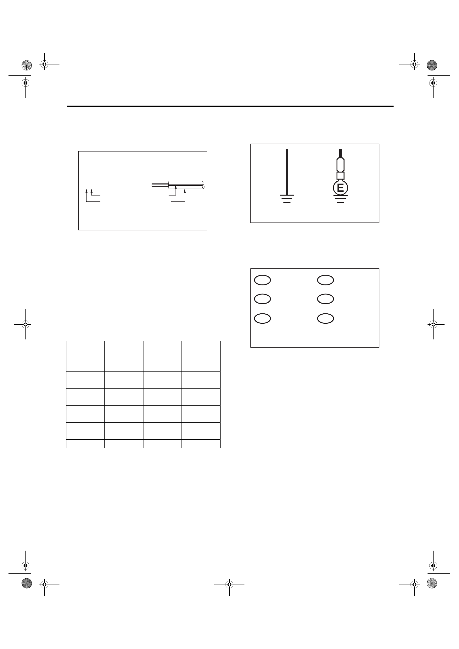
•WIRING DIAGRAM:
The connectors are numbered along with the number of poles, external colors, and mating connections in the accompanying list.
•The sketch of each connector in the wiring diagram usually shows the (A) side of the connector.
The relationship between the wire color, terminal
number and connector is described in the figure.
•The following color codes are used to indicate
the colors of the wires.
Color code Color
LBlue
BBlack
YYellow
GGreen
RRed
WWhite
Br Brown
Lg Light green
Gr Gray
PPink
Or Orange
Sb Light blue
V Violet
SA Sealed (Inner)
SB Sealed (Outer)
YG
NOTE:
A wire which runs in one direction from a connector
terminal sometimes may have a different color from
that which runs in the other direction from that terminal.
i2
BR
1
RW
3
Wire color :
(No. 1 terminal)
BR
RW (No. 3 terminal)
(A)
i2F4
12
34
WI-02748
•In the wiring diagram, connectors which have no
terminal number refer to one-pole types. Sketches
of these connectors are omitted intentionally.
BB
SA
SB10
YL9
YG8
SB22
SA20
SB
YL
SB
YL 2
YG 1
SA 1
WI-00110
B15F10
WI-00109
WI-6
08TR_VDC_US.book 7 ページ 2012年2月10日 金曜日 午後1時43分
Basic Diagnostic Procedure
WIRING SYSTEM
•The wire color code, which consists of two letters
(or three letters including Br or Lg), indicates the
standard color (base color of the wire covering) by
its first letter and the stripe marking by its second
letter.
YB
BlackMarking color :
Reference color : Yellow
WI-03797
•The table lists the nominal sectional areas and
allowable currents of the wires.
CAUTION:
When replacing or repairing a wire, be sure to
use the same size and type of the wire which
was originally used.
NOTE:
•The allowable current in the table indicates the
tolerable amperage of each wire at an ambient
temperature of 40°C (104°F).
•The allowable current changes with ambient
temperature. Also, it changes if a bundle of more
than two wires is used.
Nominal
sectional
area
mm
0.3 7/0.26 1.8 7
0.5 7/0.32 2.2 (or 2.0) 12
0.75 30/0.18 2.6 (or 2.4) 16
0.85 11/0.32 2.4 (or 2.2) 16
1.25 16/0.32 2.7 (or 2.5) 21
226/0.323.1 (or 2.9)28
341/0.323.8 (or 3.6)38
565/0.324.6 (or 4.4)51
850/0.455.5 67
2
No. of
strands/
strand
diameter
Outside
diameter of
wiring
mm
Allowable
current
Amps/
40°C (104°F)
•Each unit is either directly grounded to the body
or indirectly grounds through a harness ground terminal. Different symbols are used in the wiring diagram to identify the two grounding systems.
B
Direct ground Indirect terminal
ground
WI-02750
•The ground points shown in the wiring diagram
refer to the following:
NOTE:
All wiring harnesses are provided with a ground
point which should be securely connected.
: AIRBAG GROUND
GAB
: BODY GROUND
GB
: REAR DEFOGGER
GD
GROUND
: ENGINE GROUND
GE
: RADIO GROUND
GR
: VDC GROUND
GV
WI-19724
WI-7

08TR_VDC_US.book 8 ページ 2012年2月10日 金曜日 午後1時43分
Basic Diagnostic Procedure
WIRING SYSTEM
•Relays are classified as normally-open or normally-closed.
The normally-closed relay has one or more contacts. The wiring diagram shows the relay mode when the energizing circuit is OFF.
Relay type
Normally-open type
Normally-closed type
4-pole
6-pole
4-pole
Energizing circuit OFF
Energizing circuit ON
Mixed type
Key to symbols:
: Current flows.
: Current does not flow.
6-pole
WI-16724
WI-8

08TR_VDC_US.book 9 ページ 2012年2月10日 金曜日 午後1時43分
Basic Diagnostic Procedure
•Each connector number shown in the wiring diagram corresponds to that in the wiring harness. The
location of each connector in the actual vehicle is
determined by reading the first character of the
connector (for example, a “F” for F8, “i” for i16, etc.)
and the type of wiring harness. The first character
of each connector number corresponds to the area
or system of the vehicle.
Symbol Wiring harness and cord
FFront wiring harness
BBulkhead wiring harness
EEngine wiring harness
TTransmission cord
D
iInstrument panel wiring harness
R
AB Airbag wiring harness
Door cord LH & RH, Rear gate cord
Rear door cord LH & RH, Rear defogger cord
Rear wiring harness,
Fuel tank cord,
Roof cord, Rear gate cord,
Rear defogger ground cord (Sedan model)
WIRING SYSTEM
F58
F23
F98
FRONT TURN SIGNAL
LIGHT LH (UPPER)
FRONT TURN SIGNAL
LIGHT LH (LOWER)
F19
F22
F100
F21
F47
F5
F27
F34
F96
Each connector number
shown in wiring diagram
corresponds to that in
BG2
B1
F19
BG3
B2
F22
the vehicle.
(GRAY)
F3
(GRAY)
F19
1 2
WI-02753
WI-9
08TR_VDC_US.book 10 ページ 2012年2月10日 金曜日 午後1時43分
Basic Diagnostic Procedure
WIRING SYSTEM
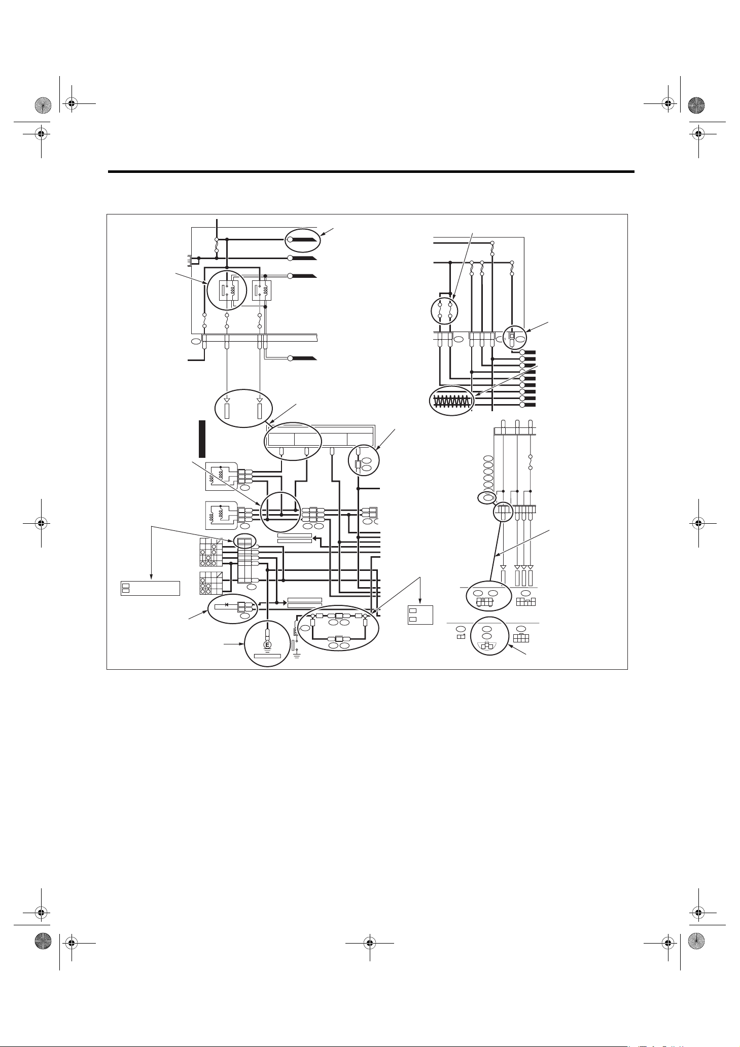
D: SYMBOLS IN WIRING DIAGRAMS
A number of symbols are used in each wiring diagram to easily identify parts or circuits.
Example
RELAY
SYMBOLS OF
WIRE
CONNECTION
AND CROSSING
SPECIFICATION
CLASSIFICATION
: WITHOUT REAR D EFOGGER
OR
: WITH RE AR DEFO GGER
WR
DIODE
SBF-1 100A
HEADLIGHT
RELAY
RH
No.3 10A
3
F39
LR
H/L(2L)-01
HEADLIGHT LH
LOW
HEADLIGHT RH
LOW
DIMMER &
PASS IN G SWI TC H
UP
LOW PA SS
LIGHTING SWITCH
1
2
OFF
GROUND
HF
HU
HL
HC
TC
EL
DIODE
E
No.9 15A
7
LW
MB-11
HIGH
HIGH
MAIN FUSE B OX (M/ B)
HEADLIGHT
RELAY
LH
No.8 15A
2
RL
MB-10
RL2
R1
YL3
F23
LW2
R1
YL3
F7
WROR
3
LY8
RY7
2
17
YB
16
B1716
LY
13 13
B71
YB1
RY2
B112
REF TO. GND-02
5
G
MB-10
M/B FUSE NO. 8
B
P-SUP-02
A
P-SUP-02
B
P-SUP-02
C
P-SUP-04
D
POWER SUPPLY
ROUTING
TO POWE R SUP PLY CIRC UIT
FB-16
MB-11
F/B FUSE NO. 11
M/B FUSE NO. 9
RL
LW
LW 4
LW
R3
R
YL
2
YL
F44
REF TO. FOG(H4)-01
REF TO. FOG(H6)-01
P
R4
PARK IN G
BRAKE
SWITCH
B61
SD SD
WG
REF TO. ST(MT)-01
REF TO. ST(AT)-01
WIRE TRACING
ON EXTENDED
WIRING DIAGRAMS
MB-5
HEADLIGHT
RELAY
(IG)
LB
GR
F45
B62
LB H1
LW B1
RA1
B36
SMJ
SMJ
SMJ
SPECIFICATION
CLASSIFICATION
P P17
R3
B99
WG
P P7
R1
B97
FUSE No. & RATING
SBF-6 30A
SBF-4 50A
SBF-3 50A
No.2 15A
SBF-2 50A
No.1 20A
CONNECTOR-1
2
R
LR
L
FUSE &
RELAY
BOX (F /B)
F36 F38F68
R 3
W
BW 2
A:
B51
B:
i5
C:
B52
D:
B152
E:
B158
F:
F40
G:
F41
P-SUP-04
M
P-SUP-04
L
P-SUP-04
K
TWISTED PAIR LINE
P-SUP-04
J
P-SUP-03
I
P-SUP-03
H
P-SUP-04
G
P-SUP-03
F
P-SUP-04
E
Or
BG
LgB
D4
D7
D11
No.5 10A
A2
A3
BL G1
BR D10
BG G7
WR G4
1
3
CONNECTOR-2
FB-37
FB-35
FB-34
FB-36
G:
(GRAY)
F41
(BLACK)
(BLACK)
A:
1 2 3
4 5 6 7 8
F44
1234
5 6 7 8
B51
C:
B52
1 2 3
: SEDAN
SD
: WAGON
WG
4 5 6 7
B112
F7
F23
1 2
123
CONNECTOR SKETCH
WI-16198
WI-10
08TR_VDC_US.book 11 ページ 2012年2月10日 金曜日 午後1時43分
Basic Diagnostic Procedure
WIRING SYSTEM
1. RELAY
A symbol used to indicate a relay.
2. CONNECTOR 1
The sketch of the connector indicates the one-pole
types.
3. WIRING CONNECTION
Some wiring diagrams are indicated in foldouts for
convenience. Wiring destinations are indicated
where necessary by corresponding symbols.
(When two pages are needed for clear indication)
4. FUSE NO. & RATING
The “FUSE No. & RATING” corresponds with that
used in the fuse box (main fuse box, fuse and joint
box).
5. CONNECTOR 2
•Each connector is indicated by a symbol.
•Each terminal number is indicated in the corresponding wiring diagram in an abbreviated form.
•For example, terminal number “G4” refers to No.
4 terminal of connector (G: F41) shown in the connector sketch.
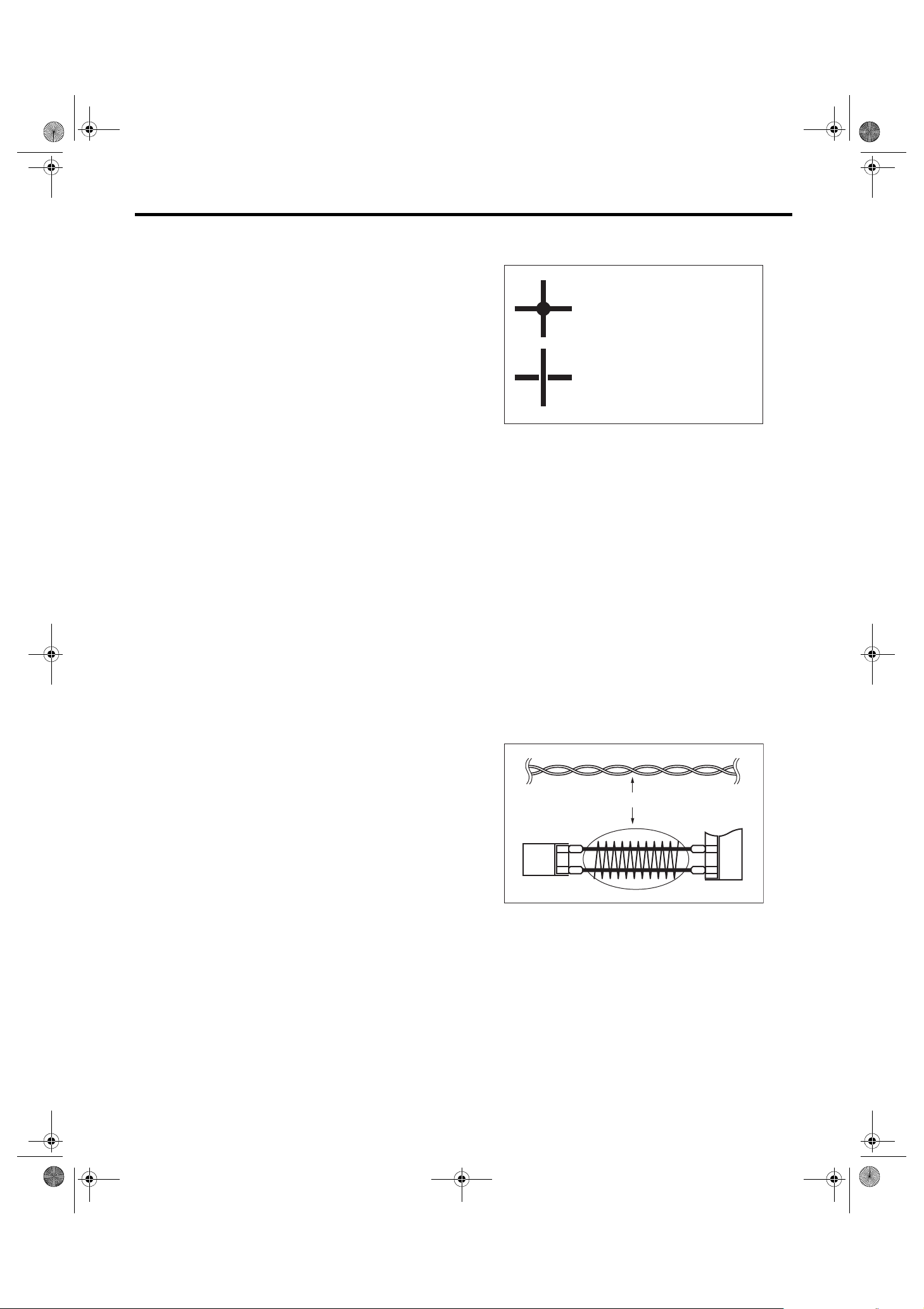
10.SYMBOLS OF WIRE CONNECTION AND
CROSSING
Symbol
Symbol Refers to wires which are
Refers to wires which are
connected and branched
at the dot point.
crossed but not connected.
WI-02755
11.POWER SUPPLY CIRCUIT
A symbol is used to indicate the power supply in
each wiring diagram.
“MB-5”, “MB-6”, etc., which are used as power supply symbols throughout the text, correspond with
those shown in the “DC POWER SUPPLY CIRCUIT” in the wiring diagram.
Accordingly, using the “DC POWER SUPPLY CIRCUIT” and wiring diagrams permits service personnel to understand the entire electrical arrangement
of a system.
6. CONNECTOR SKETCH
•Each connector sketch clearly identifies the
shape and color of a connector as well as terminal
locations. Non-colored connectors are indicated in
white or natural color.
•When more than two types of connector number
are indicated in a connector sketch, it means that
the same type connectors are used.
7. GROUND
Each grounding point can be located easily by referring to the corresponding wiring harness.
8. DIODE
A symbol is used to indicate a diode.
9. WIRE TRACING ON EXTENDED WIRING
DIAGRAMS
For a wiring diagram extending over at least two
pages, a symbol (consisting of the same characters
with arrows), facilitates wire tracing from one page
to the next.
A ←→ A, B ←→ B
12.CLASSIFICATION BY SPECIFICATION
When the wiring diagram differ according to vehicle
specifications, the specification difference is described by using abbreviations.
13.TWISTED PAIR LINE
The twisted pair line is indicated by a symbol in the
wiring diagrams.
TWISTED PAIR LINE
B26
10
P
9
V
P
V B25
WI-16199
WI-11
08TR_VDC_US.book 12 ページ 2012年2月10日 金曜日 午後1時43分
Basic Diagnostic Procedure
WIRING SYSTEM
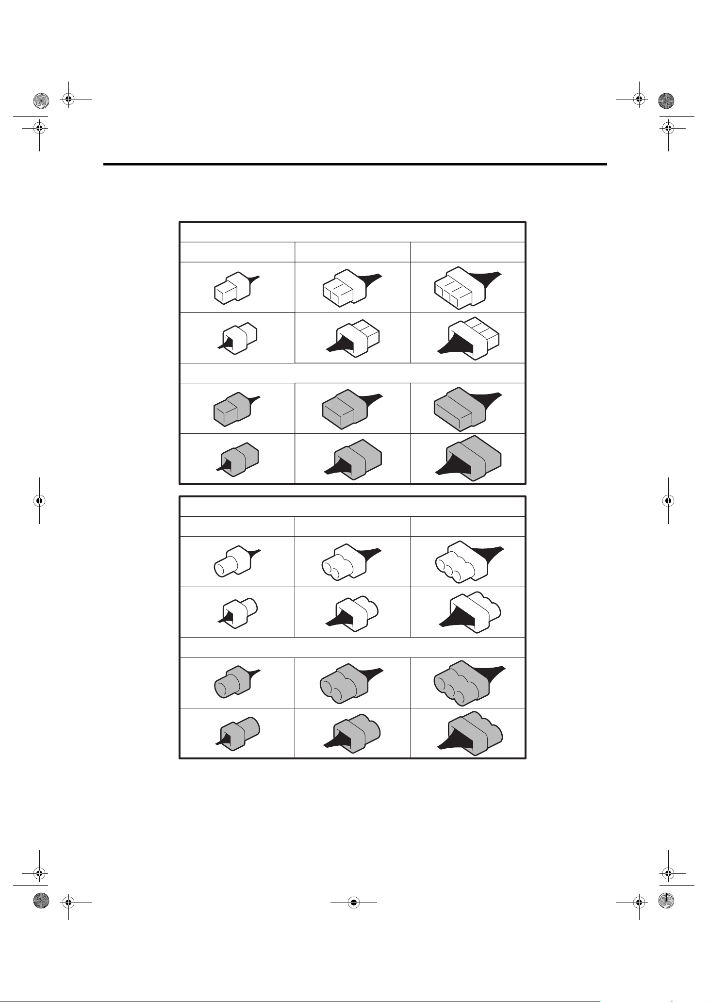
E: CONNECTOR SYMBOL IN WIRING HARNESS
A number of connector symbols are used in each wiring diagram to easily identify the wiring harness connectors.
Standard type: Female
Pole: From 1 to 8 Pole: From 9 to 20 Pole: More than 21
Standard type: Male
Water proof type: Female
Pole: From 1 to 8 Pole: From 9 to 20 Pole: More than 21
Water proof type: Male
WI-02756
WI-12

08TR_VDC_US.book 13 ページ 2012年2月10日 金曜日 午後1時43分
Basic Diagnostic Procedure
F: ABBREVIATION IN WIRING
DIAGRAMS
Abbr. Full name
A/C Air Conditioner
A/F Air/Fuel (Air fuel ratio sensor)
ABS Anti-lock Brake System
ACC Accessory
ALT Generator
ASSY Assembly
AT E l ec t r on i c al l y c o n trolled fully-automatic
AUX Auxiliary Audio Input Terminal
AWD All Wheel Drive
B, BAT Battery
CAN Controller Area Network
CPU Central Processing Unit
ECM Engine Control Module
EEPROM
EGR Exhaust Gas Recirculation
F/B Fuse & Relay box
FWD Front Wheel Drive
GPS Global Positioning System
H/L Headlight
HI High
HID High Intensity Discharge
I/F Interface
IG Ignition
L, LH Left Hand
LCD Liquid Crystal Display
LO Low
M/B Main Fuse Box
MFD Multi Function Display
OP Optional Parts or Open
R, RH Right Hand
SBF Slow Blow Fuse
ST Starter
TCS Traction Control System
TCM AT Control Module
TPM Tire Pressure Monitor
U, UP Up
VDC Vehicle Dynamics Control
Electronically Erasable and Programmable Read Only Memory
WIRING SYSTEM
WI-13

08TR_VDC_US.book 14 ページ 2012年2月10日 金曜日 午後1時43分
Working Precautions
WIRING SYSTEM
2. Working Precautions
A: PRECAUTIONS WHEN WORKING
WITH THE PARTS MOUNTED ON
THE VEHICLE
1) When working under a vehicle which is jackedup, always be sure to use rigid rack.
2) The parking brake must always be applied during working. Also, in automatic transmission vehicles, keep the select lever set to the P (Parking)
range.
3) Be sure the workshop is properly ventilated
when running the engine. Further, be careful not to
touch the belt or fan while the engine is operating.
4) Be careful not to touch hot metal parts, especially the radiator and exhaust system immediately after the engine has been turned off.
B: PRECAUTIONS IN TROUBLE
DIAGNOSIS AND REPAIR OF
ELECTRIC PARTS
1) The battery cable must be disconnected from
the battery’s (–) terminal, and the ignition switch
must be set to the OFF position, unless otherwise
required by the diagnostics.
2) Securely fasten the wiring harness with clamps
and clips so that the harness does not interfere with
the body end parts or edges and bolts or screws.
3) When installing parts, be careful not to catch
them on the wiring harness.
4) When disconnecting a connector, do not pull the
wires, but pull while holding the connector body.
5) Some connectors are provided with a lock. One
type of such a connector is disconnected by pushing the lock, and the other, by moving the lock up.
In either type the lock shape must be identified before attempting to disconnect the connector.
To connect, insert the connector until it snaps and
confirm that it is connected securely.
EXAMPLE
WI-02758
6) When checking continuity between connector
terminals, or measuring voltage across the terminal
and ground, always contact tester probe(s) on terminals from the wiring connection side. If the probe
is too thick to gain access to the terminal, use “mini”
test leads.
To check water-proof connectors (which are not
measurable from the wiring side), contact test
probes on the terminal side. Be careful not to bend
or damage the terminals.
WI-02757
WI-09366
7) Sensors, relays, electrical unit, etc., are sensitive to strong impacts.
Handle them with care so that they are not dropped
or mishandled.
WI-14

08TR_VDC_US.book 15 ページ 2012年2月10日 金曜日 午後1時43分
Power Supply Circuit
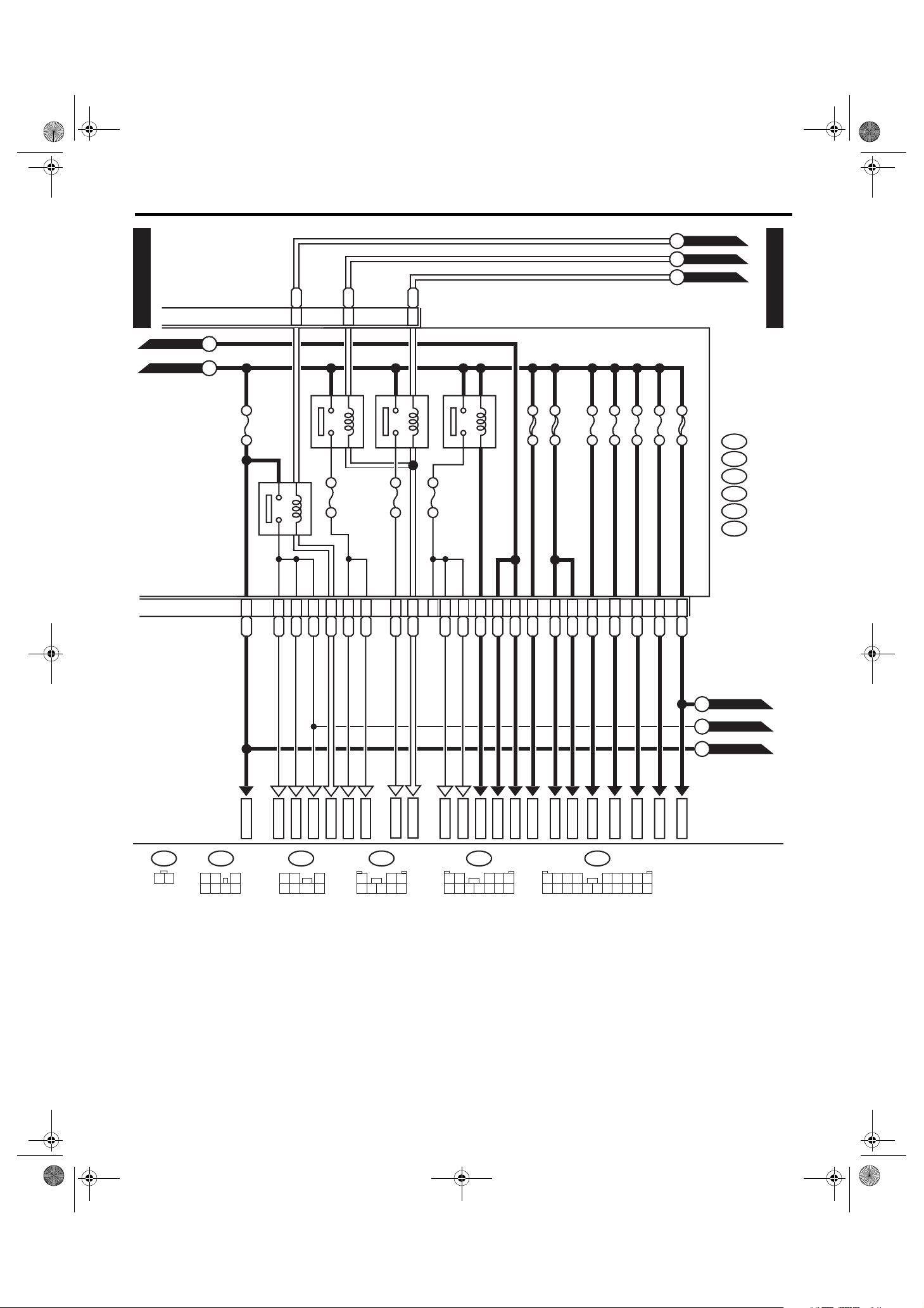
3. Power Supply Circuit
A: WIRING DIAGRAM
• VDC control module identification number W2
WIRING SYSTEM
P-SUP-01
NO. 11
NO. 12
NO. 13
NO. 14
NO. 15
NO. 16
HORN
RELAY
NO. 9
NO. 10
SBF-8
SBF-6 SBF-2
R.DEF
RELAY
TA IL
RELAY
MAIN FUSE BOX (M/B)
NO. 8
SBF-1
SBF-3
SBF-4
SBF-7
SBF-5
FUSE & RELAY BOX (F/B)
NO. 3
NO. 4
NO. 5
NO. 6
NO. 7
NO. 1
NO. 2
MAIN
SBF
H/L
RELAY
RH
H/L
RELAY
LH
P-SUP-01
NO. 27
NO. 28
NO. 29
NO. 30
NO. 31
NO. 32
NO. 33
NO. 20
NO. 21
NO. 22
NO. 23
NO. 24
NO. 25
NO. 26
NO. 13
NO. 14
NO. 15
NO. 16
NO. 17
NO. 18
NO. 19
NO. 6
NO. 7
NO. 8
NO. 9
NO. 10
NO. 11
NO. 12
WI-15
NO. 1
NO. 2
NO. 3
NO. 4
NO. 5
WI-16183

08TR_VDC_US.book 16 ページ 2012年2月10日 金曜日 午後1時43分
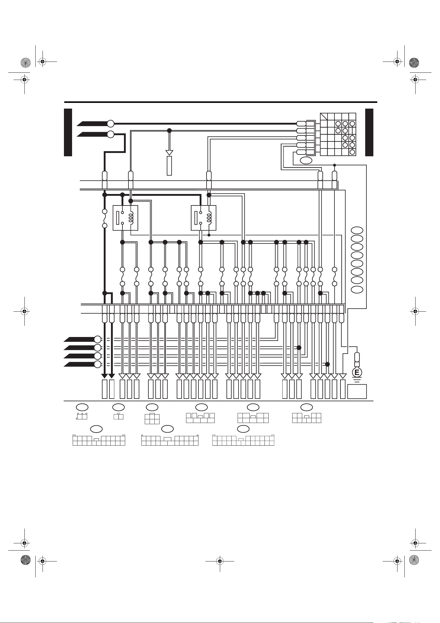
Power Supply Circuit
WIRING SYSTEM
P-SUP-02
GENERATOR
BATTE RY
80A
BAT-1
WW
2
WR
1
WB
3
BR
F26
MAI N F USE BOX (M/ B)
A:
F37
B:
B143
D:
B144
A9
A7
A16
G:
B145
H:
B186
MAIN
SBF 120A
W
No. 16 7.5A
BATTE RY CURRE NT
CURRENT FROM IGNITION SWITCH
"IG" TERMINAL
CURRENT FROM IGNITION SWITCH
"ACC" TERMINAL
OTHE R CURRENT S
No. 1 30A
SBF-1 50A
No. 5 20A
SBF-3 50A
SBF-2 50A
SBF-8 50A
SBF-6 50A
No. 8 20A
REAR DEFOGGER RELAY
No. 10 25A
GOr
H4
P-SUP-05
A
P-SUP-03
B
P-SUP-03
C
P-SUP-02
B14
B11
L
WR D7
MB-1
ALT-2
(GREEN) (B ROWN) (BR OWN)
F26
1 2 3
B145G:
1 2 3
4 5 6 7
B186H: B144D:
123
45678
1
283 4
5
RY D5
MB-2
76
LY D1
MB-3
H8
G7
L D8
R D6
9
G D3
W D2
1234 56789
10 11 12 13 14 15 16 17 18 19 20
LR D9
MB-29
B:
B143
RL
MB-5
Lg
MB-6
P-SUP-04
D
P-SUP-05
E
P-SUP-05
F
P-SUP-04
G
P-SUP-04
H
A:
F37
1234 56789
10 11 12 13 14 15 16 17 18 19 20
WI-15974
WI-16

08TR_VDC_US.book 17 ページ 2012年2月10日 金曜日 午後1時43分
Power Supply Circuit
P-SUP-03
P-SUP-02
C
P-SUP-02
B
No. 15 20A
GBB19
HEADLIGHT RELAY RH
BrRB18
HEADLIGHT RELAY LH
No. 6 15A
Br
B16
No. 7 15A
No. 9 15A
WIRING SYSTEM
P-SUP-05
I
P-SUP-05
J
P-SUP-05
K
P-SUP-03
MAIN FUSE
BOX (M/ B)
SBF-7 30A
HORN RELAY
SBF-5 30A
No. 11 15A
No. 12 15A
No. 13 7.5A
No. 14 15A
SBF-4 30A
B:
B143
C:
F35
E:
F36
F:
B433
G:
B145
H:
B186
TAI L & ILL UMI NAT ION REL AY
F2
C8RGC9
RL
MB-19
MB-20
1 2
6 7 8 9
H1
RW
MB-21
3
4 5
10 11 12
RW
MB-33
G1
G5
BR G6
WL
WY
WG
MB-22
MB-23
MB-34
MB-24
B:
1234 56789
10 11 12 13 14 15 16 17 18 19 20
RB E1
MB-17
B15
LY
MB-18
B6
C1
C2
H2
GY
GW
MB-13
MB-12
F36E:
1 2 3
4 5 6 7
R G3
MB-31
BY
RB B8
RG E4
MB-14
MB-16
MB-15
B186H: F35C:
123
45678
W G2
MB-32
B433
F:
1 2
(BR OWN) (BLUE)
B145G:
1 2 3
4 5 6 7
F1
WG H3
MB-25
B143
H7YR
MB-26
H5
W
MB-27
WB H6
MB-28
G4
BW
M
MB-30
P-SUP-04
L
P-SUP-04
P-SUP-04
N
WI-15975
WI-17

08TR_VDC_US.book 18 ページ 2012年2月10日 金曜日 午後1時43分
Power Supply Circuit
WIRING SYSTEM
P-SUP-03
N
P-SUP-03
M
P-SUP-02
D
P-SUP-04
P-SUP-02
P-SUP-03
P-SUP-02
G
L
H
ON
OFF
W
1
TB P
2
PAR KI NG
SWITCH
B69
4
P-SUP-04
FUSE &
REL AY BOX
(F/B)
A:
i5
B:
R168
C:
B52
D:
B152
E:
B158
F:
B159
L
E6
No. 1 20A
B4
L
C23
No. 8 15A
WL E1
No. 9 20A
LB E3
No. 17 15A
LW C15
BW
E4
No. 3 15A
WG A9
No. 10 7.5A
D10
R
F6
No. 27 15A
No. 28 15A
F1
GL
No. 29 15A
C2
RL
R
LR
E2
C21
A4LR
B13LR
WG
C20
No. 16 10A
A11
V
B10
V
No. 14 15A
C5
V
Or
C4
B12
BL
C17
BL
B69 B158
12
3 4
3412 89
12 13 14 15 16 17 18 19 20 21 22 23 24
E:
1 2 3 4
7 85 6
B52C:
567
10 11
FB-1
FB-3
FB-4
FB-5
FB-6
(BR OWN) (GR AY)
B159F:
1
2
5
3 4
9
76
8
D:
B152
1 2
5 6 7 8 9
3 4
FB-8
FB-9
10
1234 56789
10 11 12 13 14 15 16 17 18 19 20
FB-10
A:
FB-11
i5
FB-12
FB-14
FB-13
FB-15
FB-16
B: R168
1234 56789
10 11 12 13 14 15 16 17 18 19 20
WI-15976
WI-18

08TR_VDC_US.book 19 ページ 2012年2月10日 金曜日 午後1時43分
Power Supply Circuit
P-SUP-02
P-SUP-02
P-SUP-05
G
E5
No. 7 15A
F
E
No. 24 15A
ACC-1
No. 30 30A
No. 31 7.5A
IG2 RELAY
No.4 7.5A
Y
F7
ACCE SSO RY RELAY 1
No. 23 15A
No. 13 20A
No. 6 7.5A
WIRING SYSTEM
IGNITION SWITCH
ACCOFF
ON ST
+B
3
W
4
6
B72
No. 32 7.5A
No. 33 7.5A
No. 22 15A
ACC
IG2
IG1
ST
L
F3
WB
F2
No. 21 7.5A
FUSE &
RELAY
BOX (F/ B)
A:
i5
B:
R168
C:
B52
D:
B152
E:
B158
F:
B159
G:
B373
H:
AB35
P-SUP-05
Y
G
L
WB12
G
F8
No. 11 7.5A
No. 18 10A
No. 5 7.5A
No. 12 15A
No. 19 7.5A
No. 25 15A
No. 26 7.5A
A17YR
FB-25
R168
F4YB
C7
FB-27
A1YR
D7YR
A5
GY
FB-28
FB-29
FB-49
B158E:G:
1 2 3 4
7 85 6
C8
A6GBD9
B18
GY
GY
FB-32
FB-48
12 13 14 15 16 17 18 19 20 21 22 23 24
C16GL
GR A8
GR C24
BrW A20
FB-34
FB-35
FB-36
FB-37
FB-38
B159F:
1
2
5 76
C:
B52
3412 89
567
3 4
8
B1YG
A10
YL
B373
1 2
YL
YW B14
FB-19
FB-21
FB-20D6FB-23
WL B11
WL C19
P-SUP-03
P-SUP-03
P-SUP-03
P-SUP-02
AB35H:
1234 56789
10 11 12 13 14 15 16 17 18 19 20
J
I
K
A
FB-17
FB-18
(BLACK) (BR OWN) (GR AY)
12
A:
i5
C3YG
FB-24
B72
13
2
456
B:
1234 56789
10 11 12 13 14 15 16 17 18 19 20
H1
9
10 11
D4
H2
G1
GOr
BrR
FB-47
D2Br
G2
C11
GB
GY
FB-41
FB-42
D:
B152
1 2
5 6 7 8 9
D3
GY
FB-44
3 4
10
A3
GOr
FB-45
C1
GOr
FB-46
D1
WG
ST-1
D8
B
REF. TO
ST-2
[GND-02]
B
GND
WI-15977
WI-19
08TR_VDC_US.book 20 ページ 2012年2月10日 金曜日 午後1時43分
Power Supply Circuit
WIRING SYSTEM
No. Load
MB-1 Fail safe relay
MB-2 VDC control module
MB-3 Accessory relay 2
MB-5 Mirror heater relay
Rear defogger
MB-6 Body integrated unit
MB-12 Headlight beam leveler RH
MB-13 Headlight beam leveler LH
MB-14 Combination switch (lighting)
MB-15 Combination meter
MB-16 Headlight RH
MB-17 Headlight LH
MB-18 Daytime running light control module
Body integrated unit
MB-19 Horn
MB-20 Horn
MB-21 Body integrated unit
Remote engine start control module
Horn switch
MB-22 Main relay
MB-23 Main relay 2
Main relay
MB-24 Electronic throttle control relay
MB-25 Fuel pump relay
MB-26 TCM
MB-27 ECM
Data link connector
MB-28 Key warning switch
Key illumination
Tu r n s ign al and ha z ar d un i t
Body integrated unit
MB-29 Spot map light
Vanity mirror l ight LH
Vanity mirror l ight RH
Puddle light LH
Puddle light RH
Foot light (Driver’s seat)
Foot light (Passenger’s seat)
Home link
Body integrated unit
Room light
MB-30 Power window circuit breaker
MB-31 F/B fuse No. 16
Headlight beam leveler switch
MB-32 Parking switch
MB-33 Blower motor relay
MB-34 Vacuum pump relay
FB-1 Trailer connector
FB-3 Stop light switch
No. Load
FB-4 Mirror heater relay
Wiper deicer relay
FB-5 Seat heater relay
FB-6 Body integrated unit
FB-8 Rear A/C relay
FB-9 Front fog light relay
FB-10 MFD
Impact sensor
Audio
Keyless entry control module
Second-row seat foot light RH
TV monitor
Navigation module
Front step light LH
Front step light RH
Rear Entertainment
Rear step light RH
XM radio
FB-11 Second-row seat foot light LH
Luggage room light
Rear gate light
Rear step light LH
FB-13 Navigation module
FB-17 TPM control module
Warning box LH
Warning box RH
Rear view camera module
Combination meter
FB-18 Auto A/C control module
Body integrated unit
FB-19 Remote control mirror switch
Push switch
FB-20 Accessory relay 2
Seat heater relay
Shade mirror
FB-21 Rear accessory power supply socket
(Third-row seat)
Rear accessory power supply socket
(Luggage room)
FB-23 Rear wiper motor
FB-24 Body integrated unit
Rear washer motor
FB-25 MFD
Audio
TV monitor
Navigation module
Rear view camera module
AUX switching unit
Rear entertainment
WI-20

08TR_VDC_US.book 21 ページ 2012年2月10日 金曜日 午後1時43分
Power Supply Circuit
No. Load
FB-27 Combination Switch (Wiper)
Front wiper motor
Wiper relay unit
FB-28 Body integrated unit
FB-29 Auto A/C control module
FB-32 Open/Close switch
Sunroof control unit and motor
Brake switch
Tilt switch
Data link connector
Wiper deicer relay
FB-34 Turn signal and hazard unit
FB-35 Daytime running light control module
Low beam relay
Back-up light relay
FB-36 MFD
Warning box RH
Combination meter
FB-37 Body integrated unit
FB-38 ECM
TCM
Fuel pump relay
FB-41 Airbag control module
FB-42 Power window relay
Main fan relay
FB-44 VDC control module
Steering angle sensor
Ya w r a t e & l a t e r a l G s e n s o r
FB-45 A/C control panel
Rear A/C relay
FB-46 A/C relay
Intake door actuator
Auto A/C control module
Pressure switch
Blower motor relay
FB-47 Occupant detection control module
FB-48 TPM control module
Power seat LH (with memor y)
FB-49 Impact sensor
TV monitor
ACC-1 Front washer motor
BAT-1 Main fan relay
ST-1 Inhibitor relay
ST-2 Starter relay
WIRING SYSTEM
WI-21

08TR_VDC_US.book 22 ページ 2012年2月10日 金曜日 午後1時43分
Power Supply Circuit
WIRING SYSTEM
• VDC control module identification number W3
P-SUP-01
NO. 11
NO. 12
NO. 13
NO. 14
NO. 15
NO. 16
HORN
RELAY
NO. 9
NO. 10
SBF-8
SBF-6 SBF-2
R.DEF
RELAY
TA IL
RELAY
MAIN FUSE BOX (M/B)
NO. 8
SBF-1
SBF-3
SBF-4
SBF-7
SBF-5
FUSE & RELAY BOX (F/B)
NO. 3
NO. 4
NO. 5
NO. 6
NO. 7
NO. 1
NO. 2
MAIN
SBF
H/L
RELAY
RH
H/L
RELAY
LH
P-SUP-01
NO. 27
NO. 28
NO. 29
NO. 30
NO. 31
NO. 32
NO. 33
NO. 20
NO. 21
NO. 22
NO. 23
NO. 24
NO. 25
NO. 26
NO. 13
NO. 14
NO. 15
NO. 16
NO. 17
NO. 18
NO. 19
NO. 6
NO. 7
NO. 8
NO. 9
NO. 10
NO. 11
NO. 12
NO. 1
NO. 2
NO. 3
NO. 4
NO. 5
WI-16183
WI-22

08TR_VDC_US.book 23 ページ 2012年2月10日 金曜日 午後1時43分
Power Supply Circuit
WIRING SYSTEM
P-SUP-02
GENERATOR
BATTE RY
80A
BAT-1
WW
2
WR
1
WB
3
BR
F26
MAI N F USE BOX (M/ B)
A:
F37
B:
B143
D:
B144
A9
A7
A16
G:
B145
H:
B186
MAIN
SBF 120A
W
No. 16 7.5A
BATTE RY CURRE NT
CURRENT FROM IGNITION SWITCH
"IG" TERMINAL
CURRENT FROM IGNITION SWITCH
"ACC" TERMINAL
OTHE R CURRENT S
No. 1 30A
SBF-1 50A
No. 5 20A
SBF-3 50A
SBF-2 50A
SBF-8 50A
SBF-6 50A
No. 8 20A
REAR DEFOGGER RELAY
No. 10 25A
GOr
H4
A
B
C
P-SUP-05
P-SUP-02
P-SUP-03
P-SUP-03
B14
B11
L
WR D7
MB-1
ALT-2
(GREEN) (B ROWN) (BR OWN)
F26
1 2 3
B145G:
1 2 3
4 5 6 7
B186H: B144D:
123
45678
1
2
5
RY D5
MB-2
76
LY D1
MB-3
3 4
8
H8
G7
L D8
R D6
9
G D3
W D2
1234 56789
10 11 12 13 14 15 16 17 18 19 20
LR D9
MB-29
B:
B143
RL
MB-5
Lg
MB-6
P-SUP-04
D
P-SUP-05
E
P-SUP-05
F
P-SUP-04
G
P-SUP-04
H
A:
F37
1234 56789
10 11 12 13 14 15 16 17 18 19 20
WI-15974
WI-23
08TR_VDC_US.book 24 ページ 2012年2月10日 金曜日 午後1時43分
Power Supply Circuit
WIRING SYSTEM
P-SUP-03
P-SUP-02
C
P-SUP-02
B
No. 15 20A
GBB19
HEADLIGHT RELAY RH
BrRB18
HEADLIGHT RELAY LH
No. 6 15A
Br
B16
No. 7 15A
No. 9 15A
P-SUP-05
I
P-SUP-05
J
P-SUP-05
K
P-SUP-03
MAIN FUSE
BOX (M/ B)
SBF-7 30A
HORN RELAY
SBF-5 30A
No. 11 15A
No. 12 15A
No. 13 7.5A
No. 14 15A
SBF-4 30A
B:
B143
C:
F35
E:
F36
F:
B433
G:
B145
H:
B186
TAI L & ILL UMI NAT ION REL AY
F2
C8RGC9
RL
MB-19
MB-20
1 2
6 7 8 9
H1
RW
MB-21
3
4 5
10 11 12
RW
MB-33
G1
G5
BR G6
WL
WY
WG
MB-22
MB-23
MB-34
MB-24
B:
1234 56789
10 11 12 13 14 15 16 17 18 19 20
RB E1
MB-17
B15
LY
MB-18
B6
C1
C2
H2
GY
GW
MB-13
MB-12
F36E:
1 2 3
4 5 6 7
R G3
MB-31
BY
RB B8
RG E4
MB-14
MB-16
MB-15
B186H: F35C:
123
45678
W G2
MB-32
B433
F:
1 2
(BR OWN) (BLUE)
B145G:
1 2 3
4 5 6 7
F1
WG H3
MB-25
B143
H7YR
MB-26
H5
W
MB-27
WB H6
MB-28
G4
BW
M
MB-30
P-SUP-04
L
P-SUP-04
P-SUP-04
N
WI-15975
WI-24

08TR_VDC_US.book 25 ページ 2012年2月10日 金曜日 午後1時43分
Power Supply Circuit
P-SUP-03
N
P-SUP-03
M
P-SUP-02
D
P-SUP-04
P-SUP-02
P-SUP-03
P-SUP-02
G
L
H
ON
OFF
W
1
TB P
2
WIRING SYSTEM
PAR KI NG
SWITCH
B69
4
P-SUP-04
FUSE &
REL AY BOX
(F/B)
A:
i5
B:
R168
C:
B52
D:
B152
E:
B158
F:
B159
L
E6
No. 1 20A
B4
L
C23
No. 8 15A
WL E1
No. 9 20A
LB E3
No. 17 15A
LW C15
BW
E4
No. 3 15A
WG A9
No. 10 7.5A
D10
R
F6
No. 27 15A
No. 28 15A
F1
GL
No. 29 15A
C2
RL
R
LR
E2
C21
A4LR
B13LR
WG
C20
No. 16 10A
A11
V
B10
V
No. 14 15A
C5
V
Or
C4
B12
BL
C17
BL
B69 B158
12
3 4
3412 89
12 13 14 15 16 17 18 19 20 21 22 23 24
E:
1 2 3 4
7 85 6
B52C:
567
10 11
FB-1
FB-3
FB-4
FB-5
FB-6
(BR OWN) (GR AY)
B159F:
1
2
5
3 4
9
76
8
D:
B152
1 2
5 6 7 8 9
3 4
FB-8
FB-9
10
1234 56789
10 11 12 13 14 15 16 17 18 19 20
FB-10
A:
FB-11
i5
FB-12
FB-14
FB-13
FB-15
FB-16
B: R168
1234 56789
10 11 12 13 14 15 16 17 18 19 20
WI-15976
WI-25
08TR_VDC_US.book 26 ページ 2012年2月10日 金曜日 午後1時43分
Power Supply Circuit
WIRING SYSTEM
P-SUP-02
P-SUP-02
P-SUP-05
G
E5
No. 7 15A
F
E
No. 24 15A
ACC-1
No. 30 30A
No. 31 7.5A
IG2 RELAY
No.4 7.5A
Y
F7
ACCE SSO RY RELAY 1
No. 23 15A
No. 13 20A
No. 6 7.5A
IGNITION SWITCH
ACCOFF
ON ST
+B
3
W
4
6
B72
No. 32 7.5A
No. 33 7.5A
No. 22 15A
ACC
IG2
IG1
ST
L
F3
WB
F2
No. 21 7.5A
FUSE &
RELAY
BOX (F/ B)
A:
i5
B:
R168
C:
B52
D:
B152
E:
B158
F:
B159
G:
B373
H:
AB35
P-SUP-05
Y
G
L
WB12
G
F8
No. 11 7.5A
No. 18 10A
No. 5 7.5A
No. 12 15A
No. 19 7.5A
No. 25 15A
No. 26 7.5A
A17YR
FB-25
R168
F4YB
C7
FB-27
A1YR
D7YR
A5
GY
FB-28
FB-29
FB-49
B158E:G:
1 2 3 4
7 85 6
C8
A6GBD9
B18
GY
GY
FB-32
FB-48
12 13 14 15 16 17 18 19 20 21 22 23 24
C16GL
GR A8
GR C24
BrW A20
FB-34
FB-35
FB-36
FB-37
FB-38
B159F:
1
2
5 76
C:
B52
3412 89
567
3 4
8
B1YG
A10
YL
B373
1 2
YL
YW B14
FB-19
FB-21
FB-20D6FB-23
WL B11
WL C19
P-SUP-03
P-SUP-03
P-SUP-03
P-SUP-02
AB35H:
1234 56789
10 11 12 13 14 15 16 17 18 19 20
J
I
K
A
FB-17
FB-18
(BLACK) (BR OWN) (GR AY)
12
A:
i5
C3YG
FB-24
B72
13
2
456
B:
1234 56789
10 11 12 13 14 15 16 17 18 19 20
H1
9
10 11
D4
H2
G1
GOr
BrR
FB-47
D2Br
G2
C11
GB
GY
FB-41
FB-42
D:
B152
1 2
5 6 7 8 9
D3
GY
FB-44
3 4
10
A3
GOr
FB-45
C1
GOr
FB-46
D1
WG
ST-1
D8
B
REF. TO
ST-2
[GND-02]
B
GND
WI-15977
WI-26

08TR_VDC_US.book 27 ページ 2012年2月10日 金曜日 午後1時43分
Power Supply Circuit
WIRING SYSTEM
No. Load
MB-1 VDC control module
MB-2 VDC control module
MB-3 Accessory relay 2
MB-5 Mirror heater relay
Rear defogger
MB-6 Body integrated unit
MB-12 Headlight beam leveler RH
MB-13 Headlight beam leveler LH
MB-14 Combination switch (lighting)
MB-15 Combination meter
MB-16 Headlight RH
MB-17 Headlight LH
MB-18 Daytime running light control module
Body integrated unit
MB-19 Horn
MB-20 Horn
MB-21 Body integrated unit
Remote engine start control module
Horn switch
MB-22 Main relay
MB-23 Main relay 2
Main relay
MB-24 Electronic throttle control relay
MB-25 Fuel pump relay
MB-26 TCM
MB-27 ECM
Data link connector
MB-28 Key warning switch
Key illumination
Tu r n s ign al and ha z ar d un i t
Body integrated unit
MB-29 Spot map light
Vanity mirror l ight LH
Vanity mirror l ight RH
Puddle light LH
Puddle light RH
Foot light (Driver’s seat)
Foot light (Passenger’s seat)
Home link
Body integrated unit
Room light
MB-30 Power window circuit breaker
MB-31 F/B fuse No. 16
Headlight beam leveler switch
MB-32 Parking switch
MB-33 Blower motor relay
MB-34 Vacuum pump relay
FB-1 Trailer connector
FB-3 Stop light switch
No. Load
FB-4 Mirror heater relay
Wiper deicer relay
FB-5 Seat heater relay
FB-6 Body integrated unit
FB-8 Rear A/C relay
FB-9 Front fog light relay
FB-10 MFD
Impact sensor
Audio
Keyless entry control module
Second-row seat foot light RH
TV monitor
Navigation module
Front step light LH
Front step light RH
Rear Entertainment
Rear step light RH
XM radio
FB-11 Second-row seat foot light LH
Luggage room light
Rear gate light
Rear step light LH
FB-13 Navigation module
FB-17 TPM control module
Warning box LH
Warning box RH
Rear view camera module
Combination meter
FB-18 Auto A/C control module
Body integrated unit
FB-19 Remote control mirror switch
Push switch
FB-20 Accessory relay 2
Seat heater relay
Shade mirror
FB-21 Rear accessory power supply socket
(Third-row seat)
Rear accessory power supply socket
(Luggage room)
FB-23 Rear wiper motor
FB-24 Body integrated unit
Rear washer motor
FB-25 MFD
Audio
TV monitor
Navigation module
Rear view camera module
AUX switching unit
Rear entertainment
WI-27

08TR_VDC_US.book 28 ページ 2012年2月10日 金曜日 午後1時43分
Power Supply Circuit
WIRING SYSTEM
No. Load
FB-27 Combination Switch (Wiper)
Front wiper motor
Wiper relay unit
FB-28 Body integrated unit
FB-29 Auto A/C control module
FB-32 Open/Close switch
Sunroof control unit and motor
Brake switch
Tilt switch
Data link connector
Wiper deicer relay
FB-34 Turn signal and hazard unit
FB-35 Daytime running light control module
Low beam relay
Back-up light relay
FB-36 MFD
Warning box RH
Combination meter
FB-37 Body integrated unit
FB-38 ECM
TCM
Fuel pump relay
FB-41 Airbag control module
FB-42 Power window relay
Main fan relay
FB-44 VDC control module
Steering angle sensor
Ya w r a t e & l a t e r a l G s e n s o r
FB-45 A/C control panel
Rear A/C relay
FB-46 A/C relay
Intake door actuator
Auto A/C control module
Pressure switch
Blower motor relay
FB-47 Occupant detection control module
FB-48 TPM control module
Power seat LH (with memor y)
FB-49 Impact sensor
TV monitor
ACC-1 Front washer motor
BAT-1 Main fan relay
ST-1 Inhibitor relay
ST-2 Starter relay
WI-28
08TR_VDC_US.book 29 ページ 2012年2月10日 金曜日 午後1時43分
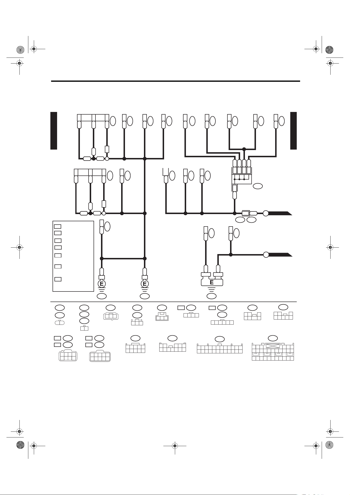
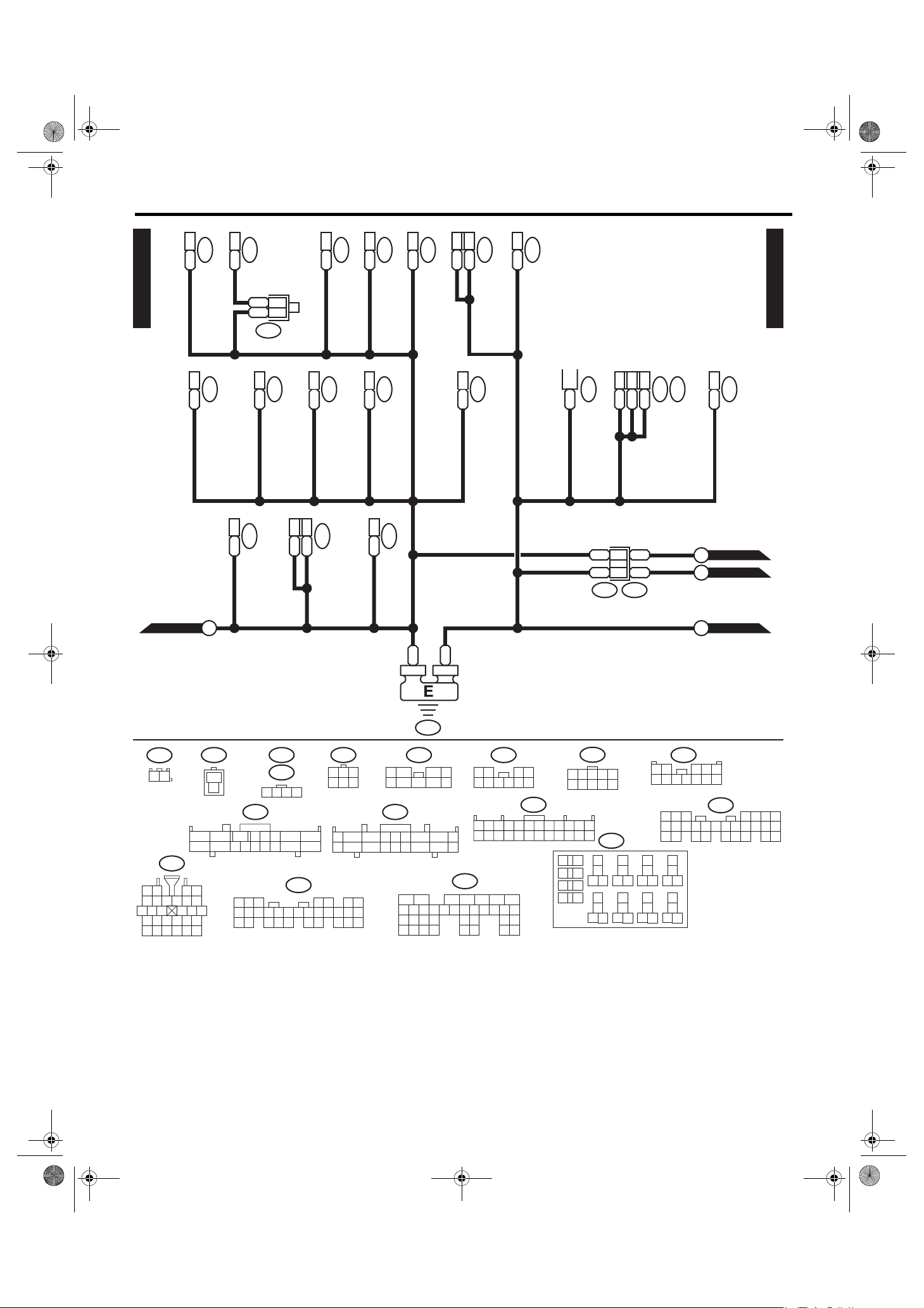
Ground Circuit
4. Ground Circuit
A: WIRING DIAGRAM
• VDC control module identification number W2
2
3
*
A16
B
BY
GND-01
HEADLIGHT &
HEADLIGHT BEAM LEVELER &
FRONT CLEARANCE &
FRONT TURN SIGNAL LIGHT RH
2
*
A16
B
BY
HEADLIGHT &
HEADLIGHT BEAM LEVELER &
FRONT CLEARANCE &
FRONT TURN SIGNAL LIGHT LH
: WITHOUT SUNROOF
OS
: WITH SUNROOF
WS
WH
: HID MODEL
OH
: EXCEPT FOR
HID MODEL
1
: TERMI NAL No.
*
OPTIONAL
ARRANGEMENT
: HID MODEL : 7
2
*
EXCEPT FOR
HID MODEL : 6
3
: HID MODEL : 6
*
EXCEPT FOR
HID MODEL : 5
*
BB
B
BBY
3
*
BB
B
BBY
KEYLESS BUZZER
B10
WH
F23
B10
WH
F102
B2
B
F7
F6
B2
FRONT FOG LIGHT RH
F21
B2
FRONT FOG LIGHT LH
F36
B E7
E:
RADIATOR FAN
MAI N F USE BOX (M/ B)
B
B1
CONTROL UNIT
2
B
SHADE MIRROR
F106
R57
4
B
MODULE & MOTOR
SUNROOF CONTROL
B2
& HOME LINK
VANITY MIRROR ILLUMI. LIGHT LH
R55
R270
1
B
SPOT MAP LIGHT
R51
B2
VANITY MIRROR ILLUMI. LIGHT RH
27
B
AIR BAG
CONTROL MODULE
B
R56
ROOM LI GHT
(WITHOUT REAR
AB6
TURN SIGNAL &
B
R52
B1
ROOM LI GHT
ENTERTAINMENT)
BBB
1
1
*
B
7
B32
B
HAZARD MODULE
WIRING SYSTEM
R250
B1
(WITH REAR
ENTERTAINMENT)
REAR ENTERTAINMENT
B
*1*1*1*
JOINT
CONNECTOR
R241
B1
B90R50
A
B
GND-03
GND-02
(ROOF)
B7
R236
GND-01
F21
12
OH
OH
F6
:
:
1 2
56
(GRAY)
(GRAY)
F7
F23
3 4
7
(GRAY)
(GRAY)
8
F102
R51
R270
1 2
(BLACK)
(BLACK)
WH
WH
1 2
67
GB-1
(GRAY)
F106
1 2 3
(GRAY)
:
F7
(GRAY)
:
F23
3 4
8
9510
1234
6 7 8 9510
GB-2
:
10 11
OS
R56
1 2 3 4
12
R52
R250
1 2 3
(GRAY)
R55 AB6
R57
123
R50
2 345
1
6789
GB-6
:
R56
WS
R241
1 2 3 4 5 6
R236
123 8 9
4
13 14 15 16
567
17 18 19 20 21 22 23 24
(GRAY)
(GRAY)
10
11 12
F36E:
1 2 3
4 5 6 7
1 2 3 4 5 6
7 8 9
18 19 20 21 22 23 24 25 26 27 28
1 2 3
4 5 6 7 8
10 11 12 13 14 16 1715
B32
(YE LLOW )
WI-15978
WI-29
08TR_VDC_US.book 30 ページ 2012年2月10日 金曜日 午後1時43分
Ground Circuit
WIRING SYSTEM
GND-02
ACCE SSO RY R ELAY 2
BOX (M/ B)
MAIN FUSE
GND-01
B225
B24
D4
B
GR 20
POWE R WIN DOW RELAY
B144
D:
DAYTIME RUNN ING LIGH T
B5
WAS HER TANK
(WASHER LEVEL SWITCH)
B
B225
SHORT
CONNECTOR
1
GR
B
2
B333
B242
B A10
A:
CONTROL MODULE
B146
(LIGHTING)
COMBINATION SWITCH
B225
B40
SEAT HEATER RELAY
B1
KEY LOCK SOLENOID
B16
B2
B350
B71
MIRROR HEATER RELAY
AT SE LE CT LEV ER
(WIPER)
COMBINATION SWITCH
B225
B32
B116
B4
B70
B2
TCM
B225
B26
LOW BEA M RELAY
BY B22
BY B23
B55
B:
B231
BY 3
GND-02
STEERING ANGLE SENSOR
2
B152
BD8
D:
FUS E & RELAY BOX (F/B)
DEL IVE RY (TEST ) M ODE
CONNECTOR
BY
B421
BODY INTEGRATED UNIT
B
BY 27
B36 i1
B280
BY B22
B281
B:
C:
BY C8
BY C9
B28
BY
CONTROL UNIT
REMOTE ENGINE START
C
D
E
B334
BY 24
GND-04
GND-04
GND-03
B333
1 2
(BLUE)
B36
56782194310
11 12 13 14 15 16
17 18 19 20 21
242223 25
2726 28
(GREEN)
B421
1
2
23456718
10 11 12 13 14 15 16 17
9
B231
B350
1
2 3 4
B71
B:
B280
3
8219
10
11 12 13 14 15
21 30
22 23
24 25 26 27
16 17 18
(GRAY)
123
4 5 6
2 3 64 571 8 9
11 12 1513 14 1610 17 18
5467
19 20
28 29
1
2
5
B70
202821 22 23
B
BY
GB-4
(BR OWN) (GR AY)
B144D:B146
76
10
98
29
30
3 4
8
B: B55
11 12 13 14 15
D:
1
2
5 6 7 8 9
9
13 14 15 16 17 18 19 20 21 22 23 24
5672134
16
2524
3231
33 34 35
B152
3 4
10
B334
3412 89
567
17 18 19
26 27
A: B242
1234
6 7 8 9510
10 11 12
12
3 4
5
6
8
7
(BLACK)
B225
9
13
10
14
11 12
15 16
29
25
30
26
27
32
3128
RELAY BLOCK
B116
1 2 3 4 5
6 7 8 9
8219
20 21
21
17
22
18
20
23
19
24
37
33
38
34
35
40
3936
10 11 12
C:
10
11 12 13 14 15
B281
2422 23 25
43
567
16 17 18 19
26 27 28
WI-15979
WI-30

08TR_VDC_US.book 31 ページ 2012年2月10日 金曜日 午後1時43分
Ground Circuit
WIRING SYSTEM
GND-03
GND-01
YAW R ATE &
LATERAL G SENSOR
GND-02
1
BY
MODULE
VDC CONTROL
B43
GV
B46
B A16
BY A11
AUTO A/C
CONTROL MODULE
B310
B A16
B B24
B B26
B282
A:
B283
B:
B2
FRONT WIPER MOTOR
HOOD SWITCH
B8
B329
B2
B2
POWE R TRA NSISTOR
B86
B10
B2
PRESSURE SWITCH
B16
B2
BRAKE FLUID
LEVEL SWITCH
AUDI O
B2
WIPER DEICER
i85
B11
B177
B
i29
VACUUM P UMP
B417
B1
GND-03
A
AUDI O B RACKET G ROUND
B359
3
B116
BY 11
BY 2
BY 6
AT SELE CT LEV ER
BB2
WIPER RELAY UNIT
B410
B:
B
FUEL PUMP RELAY
B362
28
AIR BAG
BW
CONTROL MODULE
AB6
E
B116
10 11
B177 B329
21
5
12
B310
7
56 89
1 2
2 3 4 5
817 9
(BLACK)
10 11 12 13 14
(GRAY) (BLACK)
B16
1
2
12 34
6789
2 3 4
1
15 16 17 18 19 20 21 22 23 24 25 26
29 30 31 32 33 34 35 36 37 38 39 40 41 42
B417
i85
10 11 12 13614
43 44
27 28
45 46
B
BY
GB-7
B:
(GRAY) (GRAY) (GRAY) (GRAY)
21
A:
B282
12345678
10 11 12 13 14 15 16
9
B10
1
3
2
4
1
14 15
B
GB-5
132
2
BW
B8
4 5
B:
B283
3456789
16 17 18 19 20
21 22 23
1 2
4 5
3
10
11 12 13
24 25 26
GR
(BLACK) (BLACK)
B359B410 B86
1 2 3 4 51 2 3
1 2 3 4 5 6
7 8 9
18 19 20 21 22 23 24 25 26 27 28
1 2
5
6
10 11 12 13 14 16 1715
B
B362
3
4
7 8
RELAY HOLDER
(YELLOW)
AB6
WI-15980
WI-31

08TR_VDC_US.book 32 ページ 2012年2月10日 金曜日 午後1時43分
Ground Circuit
WIRING SYSTEM
BY A15
BY A16
GND-04
TV MONITOR (WITH NAVIGATION)
i88
BY 5
A/C CONTROL PANEL
GND-02
GND-02
i119
XM RADIO
BY 7
KEY LES S ENTRY
CONTROL MODULE
D
C
5
i148
BY 19
AUX SWI TCHING UNI T
i96
i145
BY 17
BY
BY
2
2
*
*
1
1
*
*
BY
BY
BY 7
IMPACT SENSOR
MFD
BY 11
*
*
BY
i129
8
i122
SBSBBY
2*2
JOINT
CONNECTOR
1*1
BY
(REAR ENTERTAINMENT)
BY
GB-3
i117
BY
MFD SWITCH
i98
i97
CONNECTOR
B
TV MONITOR
JOINT
1
*
2
*
REF. TO REAR
ENTERTAINMENT
SYSTEM [RES-01]
Y
Br
2
3
i133
i99
: TERMI NAL No. OPTIONAL
ARRANGEMENT
AMONG 19, 20, 21 AND 22
: TERMI NAL No. OPTIONAL
ARRANGEMENT
AMONG 12, 13, 14 AND 15
REMOTE CONTROL
AUDI O
i85
14
W
5
*
5
*
REF. TO
AUDI O S YSTEM
B
WR
OR
MIRROR LH
[AUD IO- 01]
10
4
2
B
B
D84
2
i76
B B
3
*
4
*
5B
D5
(DOOR LOCK SWITCH)
POWER WINDOW MAIN SWITCH
D83
2B B
i101
: TERMI NAL No. OPTIONAL
ARRANGEMENT
AMONG 7, 8 AND 9
: TERMI NAL No. OPTIONAL
ARRANGEMENT
AMONG 10, 11 AND 12
5
WR
D7
2
OR
B
REMOTE CONTROL MIRROR RH
9
2B
5BY
B
PUSH SWITCH
10
4
B
D15
2B
D17
5B
D125
GND-04
FRO NT POWER WIND OW
SUB-SWITCH
11
B
i150
3
*
4
*
i149
B
1B
i78
JOINT
CONNECTOR
GLOV E B OX ILLUM I. L IGHT
: TERMI NAL No. OPTIONAL
5
*
ARRANGEMENT
BETWEEN 5 AND 6
: WITHOUT ELECT RIC
OR
RETRACTABLE MIRROR
: WITH ELECTRIC
WR
RETRACTABLE MIRROR
i23
MIRROR SWITCH
REMOTE CONTROL
GND-05
F
GND-05
G
PAS SE NG ER'S D OOR L OC K
SWITCH
14B
8
i6
B
LEVELER SWITCH
HEADLIGHT BEAM
i39
i23
1 2
i99 i150
i149
1 2 3 4 5 6
7 8 9
123456789
11 12 13 14 15 16 17 18 19 20
D125
1 2 345
(BLACK)
10 11 12
i148
(BLACK)
(BLUE)
(GREEN)
i133
1 2 345
i85
1 2 3 4 5 6
7 8 9
10 11 12 13 14
10
4 5 6 7 8 9
1 2 3
12 13 14 15 16 17 18 19 20 21 22
OR
:
OR
:
D15
8 7 6 5 4 3
1 2 3 4 5 6 7
8 9
10 11 12 13 14 15
i97
i98
10 11
(GRAY)
D5
(GRAY)
2 1
(BLUE)
i78
1 2 3
11 12 13 14 15 16 17 18 19 20 21 22
D17
1 2 3
4 5 6 7 8
1 2 3 4 5 6
8 9
i122 i145
4 5 6 7 8 9
1 2 3
4 5 6 7 8
D7
10 11 12 13 1514716
(GREEN)
10
i88i39
i117
D83
D84
5678219
10
11 12 13 14 15
16 17 18 19
20 21
(BLACK)
(BLACK)
123
5 6
2422 23 25
i129
i96
4
123
7 8
5
4
7 8
1 2 3 4 5 6 7
8 9
10 11 12 13 14 15 16
43
123456789
17 18 19 20 21 22 23 24 25 26 27 28 29 30 31 32
6
i6
WR
:
D5
WR
:
D15
4 3 2
10 9 8 7 615
i119
(BLACK)
123 8
9
567
10412 13 14 15 16
11
10 11 12 13 14 15 16
WI-15981
WI-32
 Loading...