

Subaru Legacy 2014 User Manual

14LE_US_EN.book 3 ページ 2013年4月9日 火曜日 午後3時12分
Basic Diagnostic Procedure
WIRING SYSTEM
1. Basic Diagnostic Procedure
A: BASIC PROCEDURES
1. GENERAL DESCRIPTION
The most important purpose of diagnostics is to
quickly determine which part is malfunctioning, to
save time and labor.
2. IDENTIFICATION OF TROUBLE SYMPTOM
Determine what the problem is based on the symptom.
3. PROBABLE CAUSE OF TROUBLE
Look at the wiring diagram and check the system’s
circuit. Then check the switch, relay, fuse, ground,
etc.
4. LOCATION AND REPAIR OF TROUBLE
1) Using the diagnostics, narrow down the causes.
2) If necessary, use a voltmeter, ohmmeter, etc.
3) Before replacing certain component parts
(switch, relay, etc.), check the power supply,
ground, for open wiring harness, poor connectors,
etc. If no problem is encountered, check the component parts.
5. SYSTEM OPERATION CHECK
After repairing, ensure that the system operates
properly.
B: BASIC INSPECTION
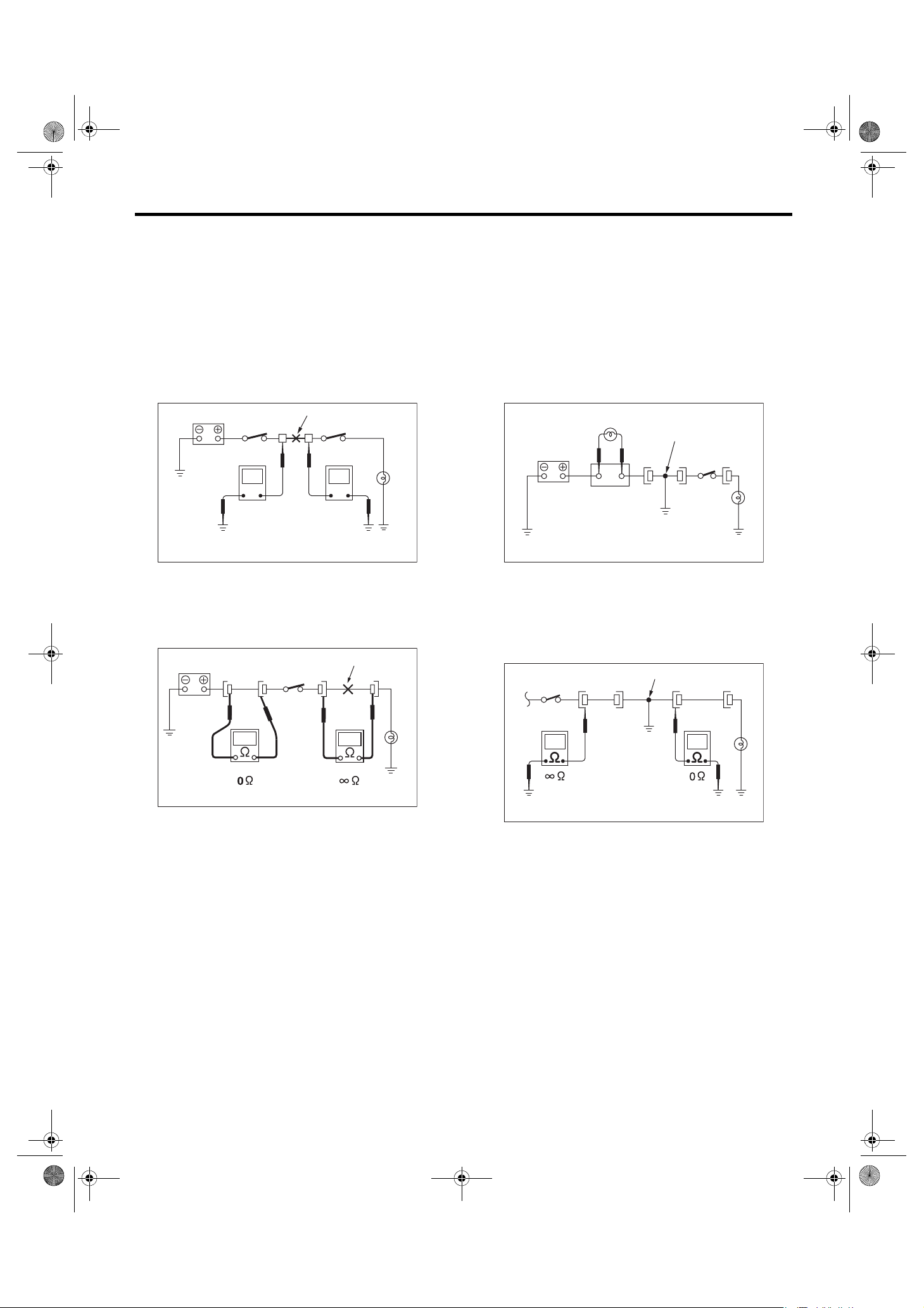
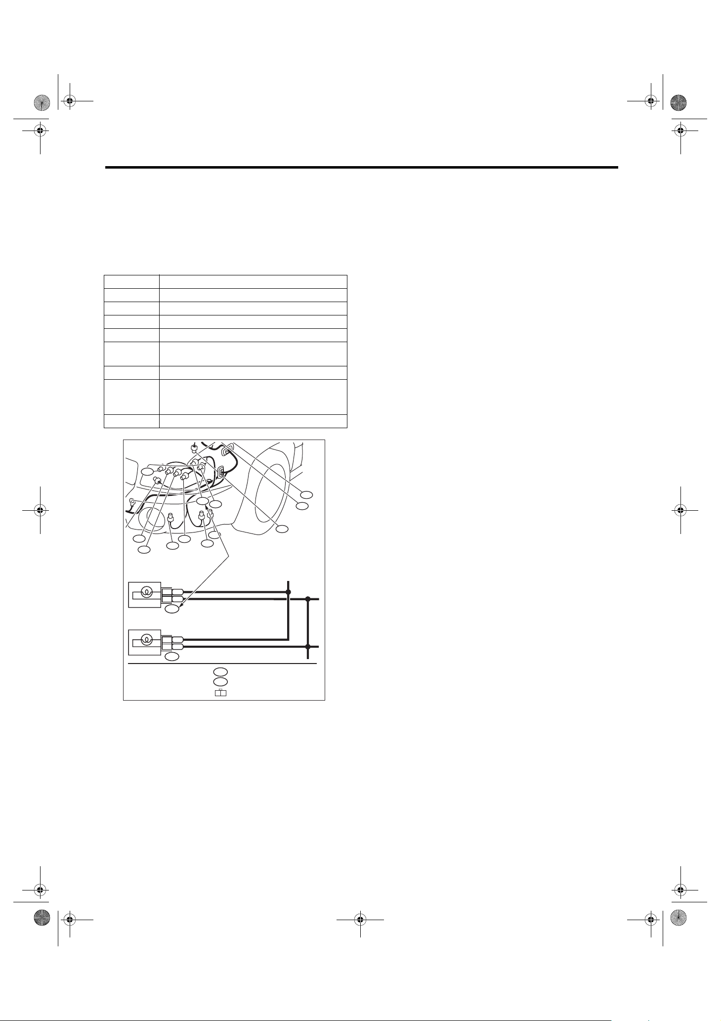
1. VOLTAGE MEASUREMENT
1) Using a voltmeter, connect the negative lead to a
good ground point or negative battery terminal and
the positive lead to the connector or component terminal.
2) Contact the positive lead of the voltmeter on
connector (A). The voltmeter will indicate a voltage.
3) Shift the positive lead to connector (B). The voltmeter will indicate no voltage.
To power
supply
Fuse
Switch
Light
5) The circuit is in good order. If a problem such as
a light failing to illuminate occurs, use the procedures outlined above to track down the malfunction.
2. CIRCUIT CONTINUITY CHECKS
1) Disconnect the battery terminal or connector so
there is no voltage between the check points.
Contact the two leads of an ohmmeter to each of
the check points.
If the circuit has diodes, reverse the two leads and
check again.
2) Use an ohmmeter to check for diode continuity.
When contacting the negative lead to the diode
positive side and the positive lead to the negative
side, there should be continuity.
When contacting the two leads in reverse, there
should be no continuity.
Continuity No continuity
WI-02740
3) The symbol “ — ” indicates that continuity
exists between two points or terminals. For example, when a switch position is at “3”, continuity exists among terminals 1, 3 and 6, as shown in the
table below.
Te rm ina l
Switch Position
OFF
1
2
3
4
1
234
56
WI-02741
(A)
(B)
V
WI-02739
4) With the test set-up held as it is, turn the switch
to ON. The voltmeter will indicate a voltage and, at
the same time, the light will illuminate.
WI-3
14LE_US_EN.book 4 ページ 2013年4月9日 火曜日 午後3時12分
Basic Diagnostic Procedure
WIRING SYSTEM
3. HOW TO DETERMINE AN OPEN CIRCUIT
1) WITH VOLTMETER:
An open circuit is determined by measuring the
voltage between respective connectors and ground
using a voltmeter, starting with the connector closest to the power supply. The power supply must be
turned ON so that current flows in the circuit. If voltage is not present between a particular connector
and ground, the circuit between that connector and
the previous connector is open.
Open circuit or wiring
V
12V
2) WITH OHMMETER:
Disconnect all connectors affected, and check continuity in the wiring between adjacent connectors.
When the ohmmeter indicates “infinite”, the wiring
is open.
V
0V
WI-02742
Open circuit
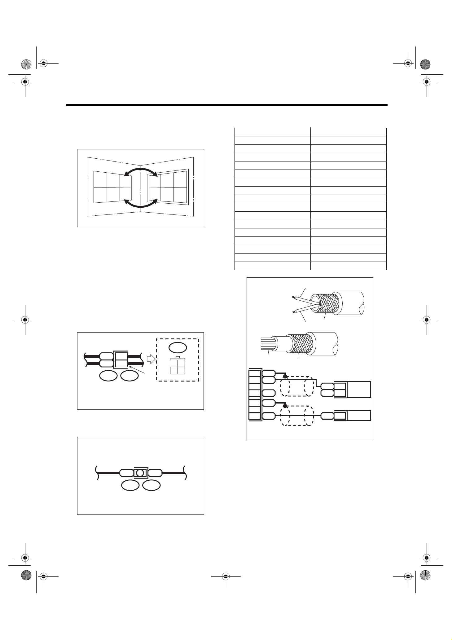
4. HOW TO DETERMINE A SHORT CIRCUIT
1) WITH TEST LIGHT:
Connect a test light (rated at approx. 3 watts) in
place of the blown fuse and allow current to flow
through the circuit. Disconnect one connector at a
time from the circuit. Starting with the one located
farthest from the power supply. If the test light goes
out when a connector is disconnected, the wiring
between that connector and the next connector
(farther from the power supply) is shorted.
Test light
Shorted wiring
Fuse holder
WI-02744
2) WITH OHMMETER:
Disconnect all affected connectors, and check continuity between each connector and ground. When
the ohmmeter indicates continuity between a particular connector and a ground, that connector is
shorted.
Shorted connector
WI-09860
WI-02745
WI-4

14LE_US_EN.book 5 ページ 2013年4月9日 火曜日 午後3時12分
Basic Diagnostic Procedure
WIRING SYSTEM
C: HOW TO READ WIRING DIAGRAMS
1. WIRING DIAGRAM
The wiring diagram of each system is illustrated so that you can understand the path through which the electric current flows from the battery.
Sketches and codes are used in the diagrams. They should read as follows:
•Each connector and its terminal position are indicated by a sketch of the connector in a disconnected state
which is viewed from the front.
2
1
3
4
4
Viewed from this direction
WI-02746
•The number of poles or pins, presence of a lock are indicated in the sketch of each connector. In the
sketch, the highest pole number refers to the number of poles which the connector has. For example, the
sketch of the connector shown in figure indicates the connector has 9 poles.
Connector used in vehicle
Sketch Symbol Number of poles
Double frames
43
98
Indicates the number of poles.
Indicates a lock is included.
12
56
Single frame
Indicates a lock
is included.
2
65
7
3
8
7
Connector shown in wiring diagram
1
4
9
Numbered in order from upper
right to lower left.
Numbered in order from upper
left to lower right.
WI-02747
WI-5
14LE_US_EN.book 6 ページ 2013年4月9日 火曜日 午後3時12分
Basic Diagnostic Procedure
WIRING SYSTEM
•When one set of connectors is viewed from the
front side, the pole numbers of one connector are
symmetrical to those of the other. When these two
connectors are connected as a unit, the poles
which have the same number are joined.
1
2
3
6
5
44
3
6
1
2
5
WI-00107
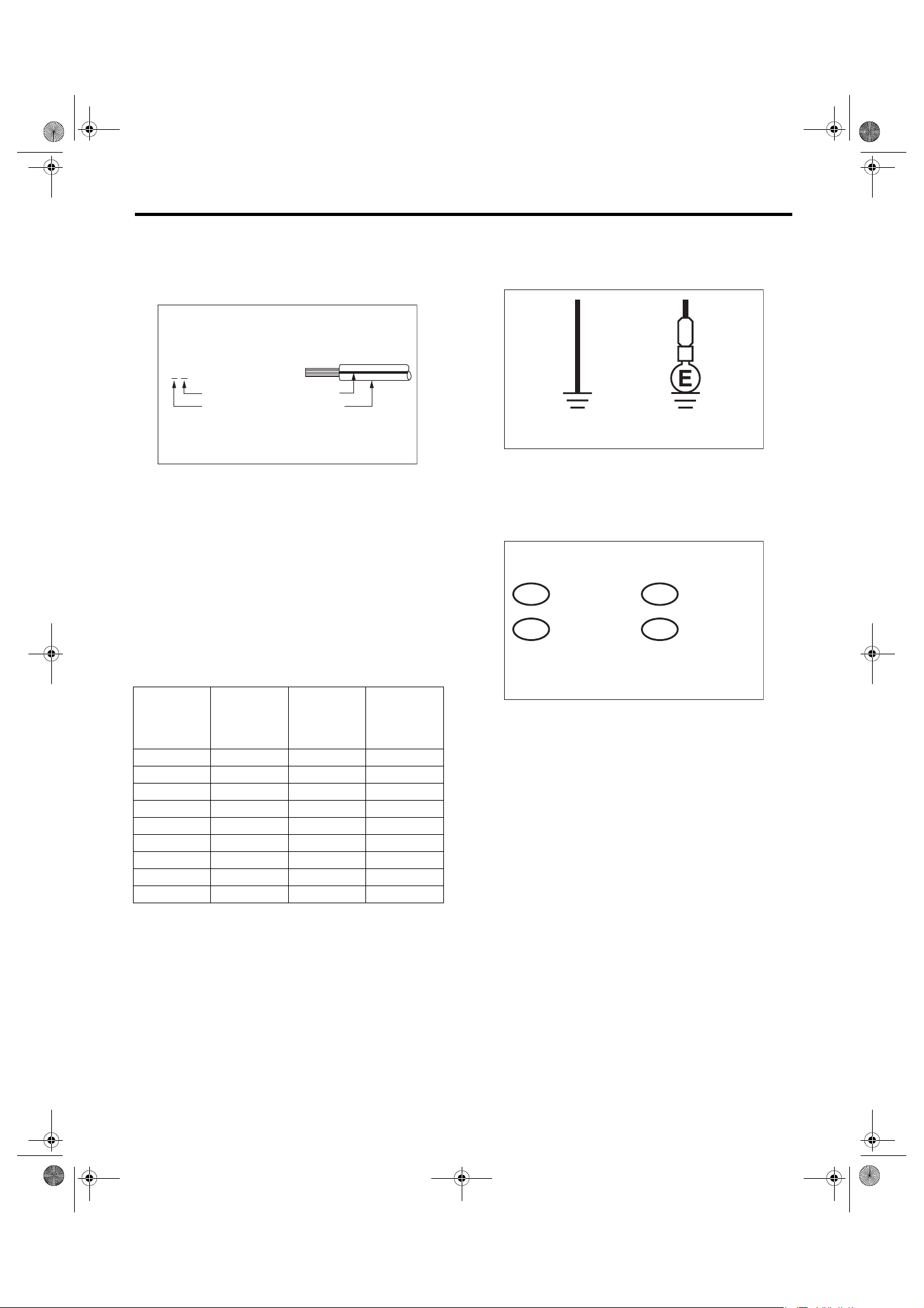
•WIRING DIAGRAM:
The connectors are numbered along with the number of poles, external colors, and mating connections in the accompanying list.
•The sketch of each connector in the wiring diagram usually shows the (A) side of the connector.
The relationship between the wire color, terminal
number and connector is described in the figure.
•The following color codes are used to indicate
the colors of the wires.
Color code Color
LBlue
BBlack
YYellow
GGreen
RRed
WWhite
Br Brown
Lg Light green
Gr Gray
PPink
Or Orange
Sb Light blue
VViolet
Be Beige
SA Sealed (inner)
SB Sealed (outer)
YG
NOTE:
A wire which runs in one direction from a connector
terminal sometimes may have a different color from
that which runs in the other direction from that terminal.
i2
BR
1
RW
3
Wire color :
BR (No. 1 terminal)
RW (No. 3 terminal)
(A)
i2F4
12
34
WI-02748
•In the wiring diagram, connectors which have no
terminal number refer to one-pole types. Sketches
of these connectors are omitted intentionally.
BB
10
SA
SB
YL9
YG8
SB22
SA20
SB
YL
SB
YL 2
YG 1
SA 1
WI-00110
B15F10
WI-00109
WI-6
14LE_US_EN.book 7 ページ 2013年4月9日 火曜日 午後3時12分
Basic Diagnostic Procedure
WIRING SYSTEM
•The wire color code, which consists of two letters
(or three letters including Br or Lg), indicates the
standard color (base color of the wire covering) by
its first letter and the stripe marking by its second
letter.
YB
BlackMarking color :
Reference color : Yellow
WI-03797
•The table lists the nominal sectional areas and
allowable currents of the wires.
CAUTION:
When replacing or repairing a wire, be sure to
use the same size and type of the wire which
was originally used.
NOTE:
•The allowable current in the table indicates the
tolerable amperage of each wire at an ambient
temperature of 40°C (104°F).
•The allowable current changes with ambient
temperature. Also, it changes if a bundle of more
than two wires is used.
Nominal
sectional
area
mm
0.3 7/0.26 1.8 7
0.5 7/0.32 2.2 (or 2.0) 12
0.75 30/0.18 2.6 (or 2.4) 16
0.85 11/0.32 2.4 (or 2.2) 16
1.25 16/0.32 2.7 (or 2.5) 21
226/0.323.1 (or 2.9)28
341/0.323.8 (or 3.6)38
565/0.324.6 (or 4.4)51
850/0.455.5 67
2
No. of
strands/
strand
diameter
Outside
diameter of
wiring
mm
Allowable
current
Amps/
40°C (104°F)
•Each unit is either directly grounded to the body
or indirectly grounds through a harness ground terminal. Different symbols are used in the wiring diagram to identify the two grounding systems.
B
Direct ground Indirect terminal
ground
WI-02750
•The ground points shown in the wiring diagram
refer to the following:
NOTE:
All wiring harnesses are provided with a ground
point which should be securely connected.
: BODY GROUND
GB
: ENGINE GROUND
GE
: RADIO GROUND
GR
: VDC GROUND
GV
WI-25479
WI-7
14LE_US_EN.book 8 ページ 2013年4月9日 火曜日 午後3時12分
Basic Diagnostic Procedure
WIRING SYSTEM
•Relays are classified as normally-open or normally-closed.
The normally-closed relay has one or more contacts. The wiring diagram shows the relay mode when the energizing circuit is OFF.
Relay type
Normally-open type
Normally-closed type
4-pole
6-pole
4-pole
Energizing circuit OFF
Energizing circuit ON
Mixed type
Key to symbols:
: Current flows.
: Current does not flow.
6-pole
WI-16724
WI-8
14LE_US_EN.book 9 ページ 2013年4月9日 火曜日 午後3時12分
Basic Diagnostic Procedure
•Each connector number shown in the wiring diagram corresponds to that in the wiring harness. The
location of each connector in the actual vehicle is
determined by reading the first character of the
connector (for example, a “F” for F8, “i” for i16, etc.)
and the type of wiring harness. The first character
of each connector number corresponds to the area
or system of the vehicle.
Symbol Wiring harness and cord
FFront wiring harness
BBulkhead wiring harness
EEngine wiring harness
TTransmission cord
D
iInstrument panel wiring harness
R
AB Airbag wiring harness
Door cord LH & RH, Rear gate cord
Rear door cord LH & RH
Rear wiring harness,
Fuel tank cord,
Roof cord, Rear gate cord,
WIRING SYSTEM
F58
F23
F98
FRONT TURN SIGNAL
LIGHT LH (UPPER)
2
1
FRONT TURN SIGNAL
LIGHT LH (LOWER)
3
2
F19
F22
F100
F21
F47
F5
F27
F34
F96
Each connector number
shown in wiring diagram
corresponds to that in
BG
B
F19
BG
B
F22
the vehicle.
(GRAY)
F3
(GRAY)
F19
1 2
WI-02753
WI-9
14LE_US_EN.book 10 ページ 2013年4月9日 火曜日 午後3時12分
Basic Diagnostic Procedure
WIRING SYSTEM
D: SYMBOLS IN WIRING DIAGRAMS
A number of symbols are used in each wiring diagram to easily identify parts or circuits.
Example
SYMBOLS OF WIRE
CONNECTION AND
CROSSING
SPECIFICATION
CLASSIFICATION
OR
WR
RELAY
: WITHOUT REAR DEFOGGER
: WITH REAR DEFOGGER
DIODE
HEAD LIGHT
RELAY
No. 3 10A
3
F39
LR
H/L(2L)-01
HEADLIGHT LH
HEADLIGHT RH
DIMMER
& PASSING
SWITCH
PASSLOW
UP
LIGHTING SWITCH
OFF
GROUND
MAIN FUSE BOX (M/B)
SBF-1 100A
HEAD LIGHT
RELAY
RH
LOW
LOW
DIODE
LH
No. 9 15A
7
WL
MB-11
2
RL
HIGH
1
R
3
YL
F23
2
WL
HIGH
R
1
3
YL
F7 B61
OR WR
8
3
7
2
YB
17
17
16
16
B
13 13
B71
YB
1
2
YR
B112
No. 8 15A
2
5
G
RL
MB-10
YL
YR
YL
B
REF. TO GND-02
P-SUP-02
A
P-SUP-02
B
P-SUP-02
C
P-SUP-04
D
POWER SUPPLY CIRCUIT
TO POWER SUPPLY CIRCUIT
MB-10
MB-11
8
M/B FUSE NO.
M/B FUSE NO.
WL
RL
WL
R
YL
F44
REF. TO ST(MT)-01
REF. TO ST(AT)-01
REF. TO FOG(H4)-01
REF. TO FOG(H6)-01
P
R4
PARKING BRAKE
SWITCH
WIRE TRACING ON
EXTENDED WIRING
DIAGRAMS
FB-16
F/B FUSE NO.
9
(IG)
GR
4
WL
3
R
2
YL
17
R3
WG
7
P
R1
FUSE No. AND RATING
SBF-6 30A
SBF-4 50A
SBF-3 50A
SBF-2 50A
No. 2 15A
No. 1 20A
132
3
2
R
LR
MB-5
HEADLIGHT
11
RELAY
LB
F45
H1
B62
LB
B1
WL
A1
R
B36
SPECIFICATION
CLASSIFICATION
:
SEDAN
SDSD
PP
B99
WG
P
B97
SD
:
WAGON
WG
B112
12
L
FUSE &
:A
:B
:C
:D
:E
:F
:G
123
4567
123
F36 F38F68
R
BW
RELAY
BOX
(F/B)
B51
i5
B52
B152
B158
F40
F41
A2
:G:C:A
F41
(GRAY)
(BLACK)
F7
BLACK)
(
F23
LgB
D4
G4
WR
FB-37
W
A3
1234
5678
BG
D7
G7
BG
FB-36
12 3
45678
F44
M
L
K
J
I
H
G
F
E
P-SUP-04
P-SUP-04
P-SUP-04
P-SUP-04
P-SUP-03
P-SUP-03
P-SUP-04
P-SUP-03
P-SUP-04
G1
BL
FB-35
B51B52
Or
D11
No. 5 10A
D10
BR
FB-34
CONNECTOR 1
TWISTED PAIR LINE
CONNECTOR 2
CONNECTOR SKETCH
WI-25263
WI-10

14LE_US_EN.book 11 ページ 2013年4月9日 火曜日 午後3時12分
Basic Diagnostic Procedure
WIRING SYSTEM
1. RELAY
A symbol used to indicate a relay.
2. CONNECTOR 1
The sketch of the connector indicates the one-pole
types.
3. WIRING CONNECTION
Some wiring diagrams are indicated in foldouts for
convenience. Wiring destinations are indicated
where necessary by corresponding symbols.
(When two pages are needed for clear indication)
4. FUSE NO. & RATING
The “FUSE No. & RATING” corresponds with that
used in the fuse box (main fuse box, fuse and joint
box).
5. CONNECTOR 2
•Each connector is indicated by a symbol.
•Each terminal number is indicated in the corresponding wiring diagram in an abbreviated form.
•For example, terminal number “G4” refers to No.
4 terminal of connector (G: F41) shown in the connector sketch.
10.SYMBOLS OF WIRE CONNECTION AND
CROSSING
Symbol
Symbol Refers to wires which are
Refers to wires which are
connected and branched
at the dot point.
crossed but not connected.
WI-02755
11.POWER SUPPLY CIRCUIT
A symbol is used to indicate the power supply in
each wiring diagram.
“MB — 5”, “MB — 6”, etc., which are used as power- supply symbols throughout the text, correspond
with those shown in the “DC POWER SUPPLY
CIRCUIT” in the wiring diagram.
Accordingly, using the “DC POWER SUPPLY CIRCUIT” and wiring diagrams permits service personnel to understand the entire electrical arrangement
of a system.
6. CONNECTOR SKETCH
•Each connector sketch clearly identifies the
shape and color of a connector as well as terminal
locations. Non-colored connectors are indicated in
white or natural color.
•When more than two types of connector number
are indicated in a connector sketch, it means that
the same type connectors are used.
7. GROUND
Each grounding point can be located easily by referring to the corresponding wiring harness.
8.DIODE
A symbol is used to indicate a diode.
9. WIRE TRACING ON EXTENDED WIRING
DIAGRAMS
For a wiring diagram extending over at least two
pages, a symbol (consisting of the same characters
with arrows), facilitates wire tracing from one page
to the next.
A ←→ A, B ←→ B
12.CLASSIFICATION BY SPECIFICATION
When the wiring diagram differ according to vehicle
specifications, the specification difference is described by using abbreviations.
13.TWISTED PAIR LINE
Twisted pair lines are indicated in the following
manner in the wiring diagrams.
TWISTED PAIR LINE
B26
10
P
9
V
P
V
B25
WI-25264
WI-11
14LE_US_EN.book 12 ページ 2013年4月9日 火曜日 午後3時12分
Basic Diagnostic Procedure
WIRING SYSTEM
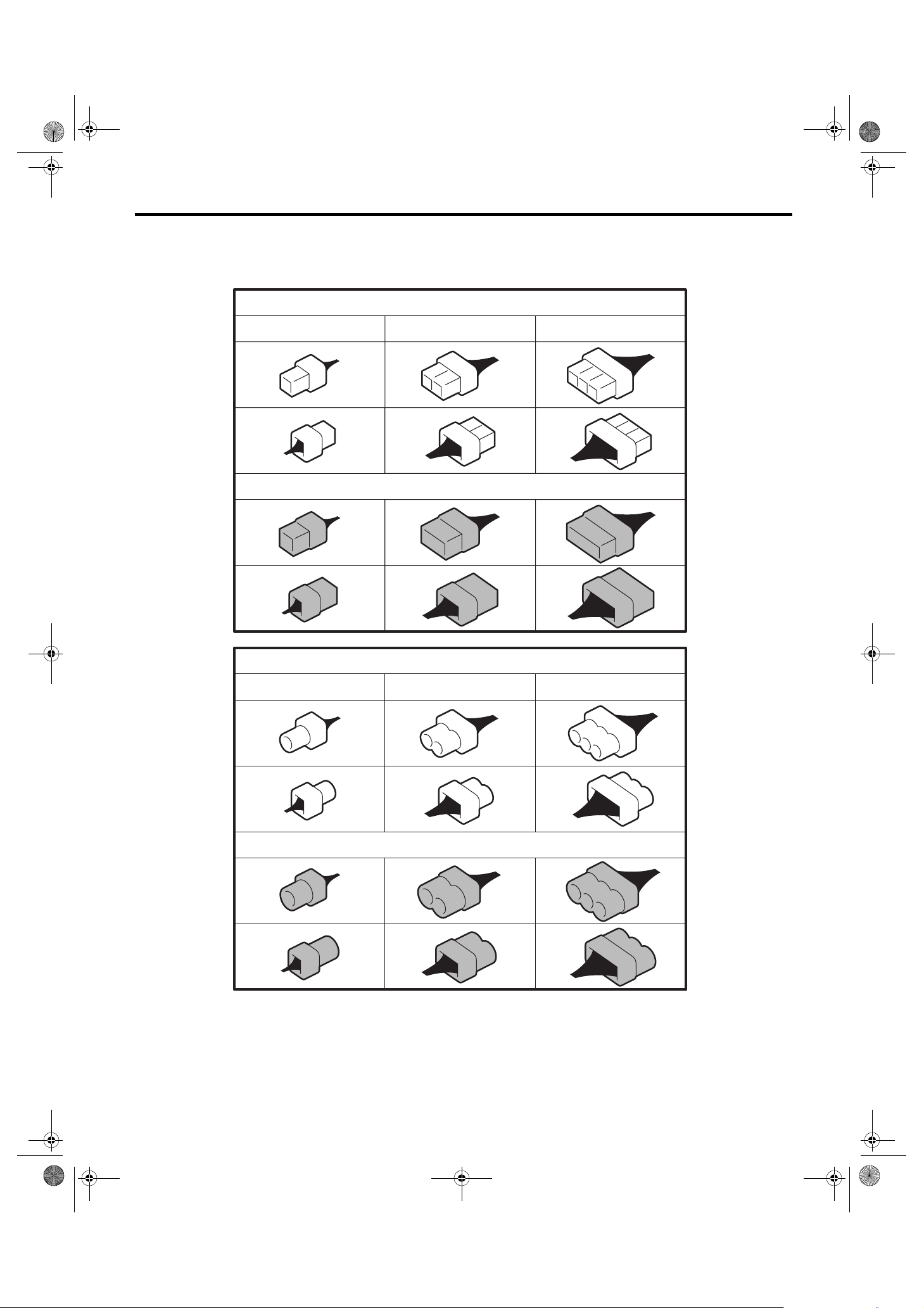
E: CONNECTOR SYMBOL IN WIRING HARNESS
A number of connector symbols are used in each wiring diagram to easily identify the wiring harness connectors.
Standard type: Female
Pole: From 1 to 8 Pole: From 9 to 20 Pole: More than 21
Standard type: Male
Water proof type: Female
Pole: From 1 to 8 Pole: From 9 to 20 Pole: More than 21
Water proof type: Male
WI-02756
WI-12
14LE_US_EN.book 13 ページ 2013年4月9日 火曜日 午後3時12分
Basic Diagnostic Procedure
F: ABBREVIATION IN WIRING DIAGRAMS
WIRING SYSTEM
Abbr. Full name
A/B Air Bag
A/C Air Conditioner
A/F Air/Fuel (Air fuel ratio sensor)
ABS Anti-lock Brake System
ACC Accessory
ALT Generator
ASSY Assembly
AT A u to ma t i c Tr a ns m i ss i o n
ATF Automatic Transmission Fluid
AWD All Wheel Drive
B, BAT Battery
CAN Communication Area Network
CM Control Module
CVT Continuously Variable Transmission
DDrive Range
DN Down
EGround
ECO Economy
ECM Engine Control Module
EEPROM
EGR Exhaust Gas Recirculation
ELCM Evaporative Leak Check Module
EPB Electronic Parking Brake
F/B Fuse & Relay Box
FL Front Left
FR Front Right
GGravity (G sensor)
H/L Headlight
HI High
I/F Interface
IG Ignition
ILLUMI Illumination
INT Intermittent
J/C Joint connector
LCD Liquid Crystal Display
L, LH Left Hand
LO Low
MMotor
M/B Main Fuse Box
MIST Wiper for mist (one touch)
MT Manual Transmission
NNeutral Range
NA Natural Aspiration
OP Optional Parts or Open
PParking Range
PA S S Pa s s in g
RReverse Range
Electrically Erasable Programmable
Read-Only Memory
Abbr. Full name
R, RH Right Hand
RL Rear Left
RR Rear Right
SBF Slow Blow Fuse
ST Starter
SW Switch
TCM Transmission Control Module
TFT Thin Film Transistor
TPMS Tire Pressure Monitor System
UP Up
VDC Vehicle Dynamics Control
VFD Vacuum Fluorescent Display
WASH Washer
WI-13

14LE_US_EN.book 14 ページ 2013年4月9日 火曜日 午後3時12分
Working Precautions
WIRING SYSTEM
2. Working Precautions
A: PRECAUTIONS WHEN WORKING
WITH THE PARTS MOUNTED ON
THE VEHICLE
1) When working under a vehicle which is jackedup, always be sure to use rigid rack.
2) The parking brake must always be applied during working. Also, in automatic transmission vehicles, keep the select lever set to the P (Parking)
range.
3) Be sure the workshop is properly ventilated
when running the engine. Further, be careful not to
touch the belt or fan while the engine is operating.
4) Be careful not to touch hot metal parts, especially the radiator and exhaust system immediately after the engine has been turned off.
B: PRECAUTIONS IN TROUBLE DI-
AGNOSIS AND REPAIR OF ELECTRIC PARTS
1) The battery cable must be disconnected from
the battery’s (–) terminal, and the ignition switch
must be set to the OFF position, unless otherwise
required by the diagnostics.
2) Securely fasten the wiring harness with clamps
and clips so that the harness does not interfere with
the body end parts or edges and bolts or screws.
3) When installing parts, be careful not to catch
them on the wiring harness.
4) When disconnecting a connector, do not pull the
wires, but pull while holding the connector body.
5) Some connectors are provided with a lock. One
type of such a connector is disconnected by pushing the lock, and the other, by moving the lock up.
In either type the lock shape must be identified before attempting to disconnect the connector.
To connect, insert the connector until it snaps and
confirm that it is connected securely.
EXAMPLE
WI-02758
6) When checking continuity between connector
terminals, or measuring voltage across the terminal
and ground, always contact tester probe(s) on terminals from the wiring connection side. If the probe
is too thick to gain access to the terminal, use “mini”
test leads.
To check water-proof connectors (which are not
measurable from the wiring side), contact test
probes on the terminal side. Be careful not to bend
or damage the terminals.
WI-02757
WI-09366
7) Sensors, relays, electrical unit, etc., are sensitive to strong impacts.
Handle them with care so that they are not dropped
or mishandled.
WI-14

14LE_US_EN.book 15 ページ 2013年4月9日 火曜日 午後3時12分
Power Supply Circuit
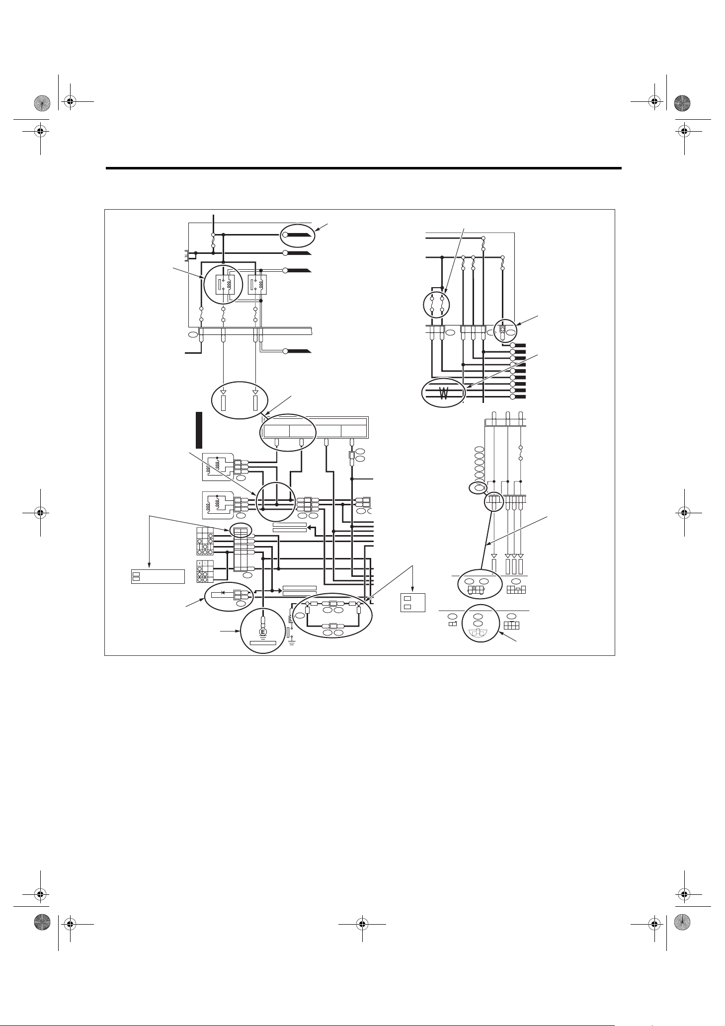
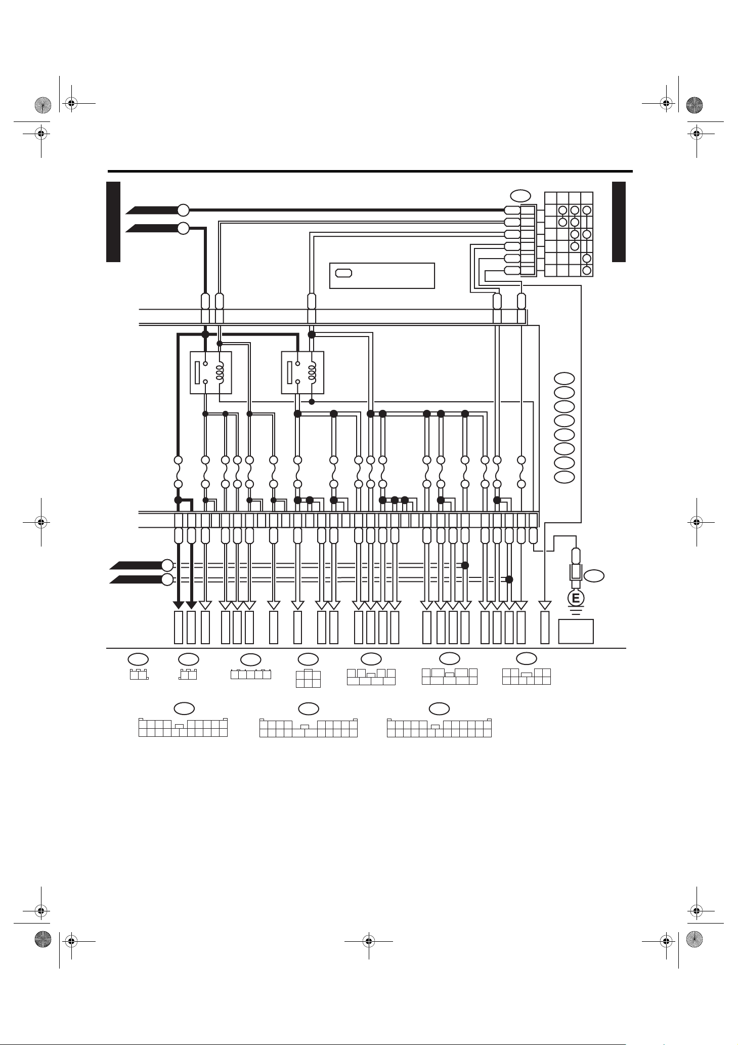
3. Power Supply Circuit
A: WIRING DIAGRAM
1. WITHOUT PUSH BUTTON START
• Engine room side
WIRING SYSTEM
P-SUP-01
MAIN FAN
DAYTIME
RUNNING
LIGHT RELAY
A/C RELAY HOLDER (3.6 L MODEL)
FRONT
DAYTIME
RUNNING
LIGHT RELAY
SUB FAN
RELAY
A/C RELAY HOLDER (2.5 L MODEL)
MAIN FAN
RELAY 1
RELAY
MAIN
FAN
RELAY
2
BAT
ALT
No. 39
12
MAIN
SBF
12
No. 38
No. 20
12
TA IL & I L LU MI
SBF-13
SBF-3
12
SBF-4
12
RELAY
1
3
SBF-11
21
12
No. 33
2
4
No. 34
No. 35
12
12
12
12
No. 32
SBF-12
SBF-9
SBF-10
21
12
12
No. 37
HORN
RELAY
21
No. 11
21
No. 12
21
No. 13
21
No. 14
21
No. 15
21
No. 16
21
No. 17
21
No. 18
21
No. 19
21
4
2
3
1
F. F O G
RELAY
1
3
2
H/L LO
RELAY
2
3
1
BRAKE
RELAY
4
532
1
SBF-2
12
POWER WINDOW
RELAY
2
1
4
No. 27
12
No. 28
12
No. 29
12
WIPER
RELAY
3
4
2
1
4
12
12
No. 24
No. 25
21
No. 26
21
H/L HI
RELAY
4
2
21
3
No. 3
21
No. 4
21
No. 5
21
No. 6
21
No. 7
21
No. 8
21
No. 9
21
1
No. 10
No. 23
R. DEF
RELAY
1
21
No. 1
No. 2
No. 21
No. 22
3
12
12
12
12
4
2
12
No. 36
SBF-5
12
SBF-6
12
SBF-7
12
SBF-8
12
M/B
P-SUP-01
4
3
21
No. 31
No. 30
WI-36108
WI-15

14LE_US_EN.book 16 ページ 2013年4月9日 火曜日 午後3時12分
Power Supply Circuit
WIRING SYSTEM
• Passenger room side
SELF
SHUT
P-SUP-02
RELAY
No. 27
No. 28
No. 29
No. 30
No. 31
No. 32
No. 33
No. 20
No. 21
No. 22
No. 23
No. 24
No. 25
No. 26
F/B FRONT SIDE
No. 13
No. 14
No. 15
No. 16
No. 17
No. 18
No. 19
No. 6
No. 7
No. 8
No. 9
No. 10
No. 11
No. 12
P-SUP-02
No. 1
No. 2
No. 3
No. 4
No. 5
MAIN
RELAY
IG
RELAY
F/B BACK SIDE
RELAY HOLDER
A/F,
OXYGEN
SENSOR
RELAY
ELECTRONIC
THR OTTLE
CONTROL
RELAY
FUEL
PUMP
RELAY
IG 2
RELAY
ACC
RELAY
WI-16
WI-41884

14LE_US_EN.book 17 ページ 2013年4月9日 火曜日 午後3時12分
Power Supply Circuit
WIRING SYSTEM
P-SUP-03
GENERATOR
B515
BATTERY
W
2
B471
W
WRWR
M/B
W
MAIN SBF 120A
1
1
No. 2 7.5A
21
SBF-8 50A
SBF-6 40A
2
2
No. 9 30A
1
No. 6 25A
2
1
1
SBF-7 50A
2
2
: 2.5 L MODEL
25
: WITH EyeSight
ES
1
No. 5 15A
2
1
No. 4 15A
No. 8 25A
2
25
1
No. 7 25A
2
25
1
1
SBF-5 40A
2
2
P-SUP-07
A
P-SUP-04
B
GB
GOr
P-SUP-04
C
P-SUP-04
D
1
1
2
3
4
REAR DEFOGGER RELAY
1
1
1
2
3
1
WIPER RELAY
4
P-SUP-03
BATTERY CURRENT
CURRENT FROM IGNITION SWITCH
"IG" TERMINAL
CURRENT FROM IGNITION SWITCH
"ACC" TERMINAL
OTHER
(GREEN)
B471
2
31
B478
3
421
No. 39 10A
21
L
5
WR
MB-1
RY
MB-2
RB
MB-3
G
GL
MB-4
G
ES
LW
MB-46
Y
MB-6
RW
MB-7
No. 22 25A
W
2
RL
MB-8
No. 29 30A
VG
MB-9
No. 28 10A
2
GW
MB-10
No. 27 15A
2
GB
MB-11
2
GMB-12
B
P-SUP-06
E
P-SUP-07
F
P-SUP-07
G
P-SUP-06
H
B
J/C
2
B478
REF. TO GND
[GND-02]
WI-36109
WI-17

14LE_US_EN.book 18 ページ 2013年4月9日 火曜日 午後3時12分
Power Supply Circuit
WIRING SYSTEM
P-SUP-03
P-SUP-04
B
: EXCEPT FOR MT MODEL
EM
1
: MT MODEL : BR
*
EXCEPT FOR MT MODEL : GR
GB
GB
P-SUP-06
I
P-SUP-07
J
P-SUP-04
P-SUP-03
C K
D
1
FRONT FOG LIGHT RELAY
1
No. 31 10A
2
LR
3
1
No. 30 10A
2
L
2
4
VY
1
No. 10 20A
2
LR
1
No. 19 20A
2
WR
1
No. 11 20A
2
WL
1
SBF-9 30A
SBF-11 30A
2
W
1
1
SBF-10 30A
2
2
BW
WG
1
2
3
BW
4
1
EM
*
POWER WINDOW RELAY
TAIL & ILLUMINATION RELAY
1
No. 35 10A
2
BL
1
3
1
No. 34 10A
2
V
2
4
LY
BW
HEADLIGHT RELAY HI
1
No. 26 10A
2
RL
1
3
1
No. 25 10A
2
RG
2
4
L
LY
HEADLIGHT RELAY LO
1
No. 24 15A
2
BrR
No. 23 15A
1
3
1
2
BrW
2
4
LY
L
M
N
P-SUP-05P-SUP-03
LG
P-SUP-06
P-SUP-06
P-SUP-06
MB-13
B517
12
MB-14
MB-15
MB-17
MB-18
MB-19
MB-20
GR
GR
MT MT
GR
1
2
B517B516
EM
B
MB-25
MB-24
MB-23
MB-22
MB-26
MB-27
MB-28
MB-29
MB-30
O
MB-31
P-SUP-05
WI-36110
WI-18

14LE_US_EN.book 19 ページ 2013年4月9日 火曜日 午後3時12分
Power Supply Circuit
WIRING SYSTEM
P-SUP-05
P-SUP-04
K
WL
BrW
3
5
BRAKE RELAY
1
ES
ES
ES
RL
2
4
HORN RELAY
1
No. 32 7.5A
No. 33 7.5A
2
REF. TO EyeSight SYSTEM
[E/S(NA)-04]
[E/S(H6)-04]
H6
1
2
3
4
1
2
1
No. 18 15A
SBF-2 80A
2
1
No. 16 15A
2
1
No. 15 15A
2
REF. TO ENGINE
ELECTRICAL SYSTEM
[E/G(NA)-05]
[E/G(H6)-14]
1
1
1
No. 14 15A
No. 13 15A
2
2
2
1
No. 20 20A
No. 12 7.5A
2
1
No. 17 10A
2
P
AT
CVT
1
No. 1 20A
2
1
1
No. 36
2
2
DELIVERY (TEST) MODE FUSE
W
1
No. 38 7.5A
2
P-SUP-06
P
REF. TO CVT CONTROL
SYSTEM
[CVT-05]
: WITH EyeSight
ES
: 3.6 L MODEL
H6
1
: MT MODEL : B478
*
EXCEPT FOR
MT MODEL : B491
2
: MT MODEL : BR
*
EXCEPT FOR
MT MODEL : B
3
: MT MODEL : 4
*
EXCEPT FOR
MT MODEL : 1
P-SUP-05
P-SUP-04
O
J/C
1
*
REF. TO
[GND-02]
2
3
GND
Br
ES
*
*
REF. TO EyeSight
SYSTEM
[E/S(NA)-04] [E/S(H6)-04]
REF. TO
[GND-01]
B478
B483
B491
421
3
5
B
ES
B
3
GND
J/C
B483
BG
RG
MB-32
R
MB-33
MB-34
W
MB-35
WB
MB-36
W
MB-37
R
MB-38
G
MB-39
L
MB-40
WG
MB-41
W
MB-42
WR
MB-43
BY
WR
MB-44
REF. TO ENGINE
ELECTRICAL SYSTEM
[E/G(NA)-05]
GY
[E/G(H6)-14]
REF. TO CVT
CONTROL SYSTEM
[CVT-05]
WI-36111
WI-19

14LE_US_EN.book 20 ページ 2013年4月9日 火曜日 午後3時12分
Power Supply Circuit
WIRING SYSTEM
P-SUP-04
P-SUP-03
P-SUP-04
P-SUP-04
P-SUP-06
P-SUP-04
P-SUP-03
: WITH NAVIGATION
WN
: WITH EyeSight
ES
F/B
A:
i5
B:
i152
C:
B52
E:
B158
F:
B159
N
E
L
I
M
H
No. 1 15A
No. 8 15A
No. 9 15A
L
E6
No. 17 15A
BW
E4
No. 3 20A
GB
F6
No. 29 20A
FB-7
GB
E8
No. 2 20A
GB
E7
No. 15 20A
BL
C5
P-SUP-06
G
F9
LR
C17
No. 14 10A
B4
LOr
P-SUP-05
E:
152
12 13 14 15 16 17 18 19 20 21 22 23 24
P
FB-1
B158
34
678
B52C:
3412 89
567
E1
C23
WL
ES
FB-2
F:
12 43
596
10 11
B159
78
E3
LB
FB-3
(BROWN)
C15
LW
A9
WG
FB-5
1234 56789
10 11 12 13 14 15 16 17 18 19 20
C2
G
FB-8
A:
i5
E2
LW
A4
LW
FB-9
12032
B13
LB
FB-10
4
13121110 1716
A7
GY
FB-13
B:
14
i152
B2
B6
A13
A11
BL
GW
FB-14
REF. TO
CLEARANCE
LIGHT &
576
15
98
19
18
F5
B10
BL
GOr
FB-15
ILLUMINATION
LIGHT SYSTEM
[ILLUMI-02]
B15
G
FB-16
C4
L
FB-41
B12
GW
WN
FB-42
WI-36112
WI-20
14LE_US_EN.book 21 ページ 2013年4月9日 火曜日 午後3時12分
Power Supply Circuit
P-SUP-03
P-SUP-03
P-SUP-07
F
G
G
E5
ACCESSORY RELAY
No. 6 7.5A
No. 7 7.5A
Y
F7
No. 13 20A
No. 20 10A
No. 24 15A
IG 2 RELAY
No. 4 7.5A
No. 31 7.5A
G
F8
1
: 2.5 L MODEL : WG
*
3.6 L MODEL : WOr
No. 18 7.5A
No. 11 7.5A
No. 12 15A
No. 5 7.5A
No. 25 15A
No. 19 7.5A
No. 33 7.5A
No. 26 7.5A
B72
W
Y
G
L
WB
1
*
L
F3
No. 22 15A
WIRING SYSTEM
IGNITION SWITCH
OFF ACC
3
5
1
4
2
6
1
*
F2
F/B
A:
i5
B:
i152
C:
B52
D:
B152
E:
B158
F:
No. 21 7.5A
B159
G:
AB35
H:
i193
STON
P-SUP-07
P-SUP-04
P-SUP-03
G: H:
AB35
12
J
A
FB-17
A:
1234 56789
10 11 12 13 14 15 16 17 18 19 20
B11
WL
i193
12
i5
C19
WL
FB-18
D6
A10
Y
FB-19
B14
Y
FB-20
A19
YV
FB-21
B491
3
A17
YR
FB-22
421
12032
C7A1D7
YR
FB-24
5
4
13121110 1716
A5
GY
FB-26
B72
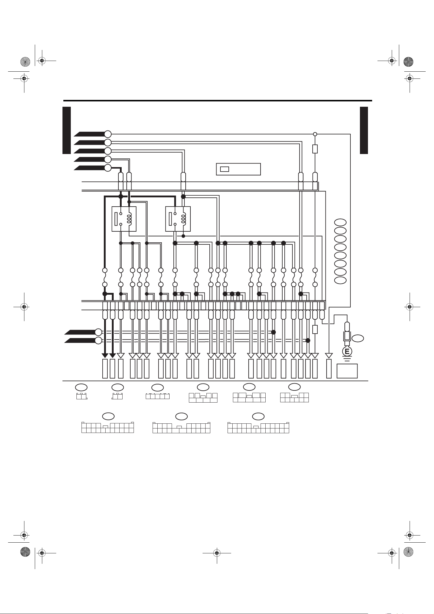
13
2
456
B:
i152
14
GOr
FB-38
D:
C1
GOr
FB-39
B152
21
D1A3D8
B
WL
ST-1
8765
B
J/C
1
B491
REF. TO
GND
ST-2
[GND-02]
(GRAY)(BLACK) (BROWN)
43
10
9
A6
D9
C8
B18
GY
FB-27
576
15
OrG
FB-28
19
18
C16
GL
FB-29
E:
152
98
A20A8C24
BrW
FB-30
B158
678
H1
G
GR
FB-32
FB-31
34
3412 89
12 13 14 15 16 17 18 19 20 21 22 23 24
H2
D4
Br
FB-33
F:
B52
GY
FB-40
FB-34
B159
78
G2
GY
G1
12 43
596
C:
567
C11
GB
FB-35
10 11
D3
GY
FB-37
WI-36113
WI-21
14LE_US_EN.book 22 ページ 2013年4月9日 火曜日 午後3時12分
Power Supply Circuit
WIRING SYSTEM
No. Load
MB-1 VDC CM
MB-2 VDC CM
MB-3 Audio connector
Audio
Audio amplifier
MB-4 Blower motor relay
MB-6 Main fan relay 1
MB-7 Sub fan relay
MB-8 Mirror heater relay
Rear defogger
MB-9 Body integrated unit
MB-10 Front wiper motor
Combination switch (wiper)
MB-11 Front washer motor
MB-12 Rear washer motor
MB-13 Front fog light RH
MB-14 Front fog light LH
MB-15 Body integrated unit
MB-17 Body integrated unit
MB-18 Sunroof motor assembly
MB-19 EPB CM
MB-20 Power seat LH
Power seat RH
Power seat (with seat position memory)
MB-22 Front combination light LH (clearance light)
Front combination light RH (clearance light)
F/B
MB-23 Satellite switch illumination
Stereo camera cover (with EyeSight)
Steering switch illumination
AT s el e c t l ev e r i l l um i n at i o n
Illumination control switch
Remote control mirror switch
Lower cover switch
Glove box light
Hill hold switch
Audio
Navigation unit
Seat heater switch (power seat)
Shower light
A/C control panel
EPB control switch
MB-24 Body integrated unit
Daytime running light relay
MB-25 Body integrated unit
MB-26 Front combination light RH (headlight)
MB-27 Front combination light LH (headlight)
MB-28 Body integrated unit
MB-29 Front combination light RH (headlight)
MB-30 Front combination light LH (headlight)
No. Load
MB-31 Body integrated unit
MB-32 Horn
MB-33 Horn
MB-34 Body integrated unit
Horn switch
MB-35 Main fan relay
MB-36 Body integrated unit
Key warning switch
Tu r n s ig na l an d h azar d u nit
MB-37 Main relay
MB-38 A/F, oxygen sensor relay
MB-39 IG relay
MB-40 Electronic throttle control relay
MB-41 Fuel pump relay
MB-42 ECM
Data link connector
MB-43 TCM
MB-44 Self shut relay
TCM
MB-46 Stereo camera
ST-1 Inhibitor relay
Starter relay
Clutch stroke sensor (clutch start switch)
ST-2 Starter relay
FB-1 Trailer connector
FB-2 Stop light and brake switch
Stop light register
Brake relay
FB-3 Seat heater relay
FB-5 Power window main switch
FB-7 Power window circuit breaker
FB-8 Front power window sub-switch
FB-9 Wiper deicer relay
FB-10 Mirror heater relay
FB-13 Rear power window sub-switch LH
FB-14 Rear power window sub-switch RH
FB-15 Body integrated unit
FB-16 Rear wiper motor
FB-17 Combination meter
Body integrated unit
Impact sensor
EPB control switch
A/C CM
FB-18 Security CM
FB-19 Remote control mirror switch
Seat heater relay
Rearview mirror (without home link)
FB-20 Rear accessory power supply socket
FB-21 Front accessory power supply socket
WI-22
14LE_US_EN.book 23 ページ 2013年4月9日 火曜日 午後3時12分
Power Supply Circuit
WIRING SYSTEM
No. Load
FB-22 Audio connector
Audio
Navigation unit
FB-24 Body integrated unit
A/C control panel
A/C CM
FB-26 Impact sensor
Wiper deicer relay
A/C control panel
Sunroof motor assembly
TPMS & keyless entry CM
Stereo camera
Power seat (with seat position memory)
Rearview mirror (with home link)
FB-27 Data link connector
Stop light and brake switch
Clutch switch
FB-28 Turn signal and hazard unit
FB-29 Inhibitor switch
Back-up light switch
Back-up light relay
FB-30 Combination meter
Clock
FB-31 A/C CM
Body integrated unit
FB-32 TCM
ECM
Fuel pump relay
FB-33 Hill hold switch
EPB CM
FB-34 Airbag CM
FB-35 Main fan relay 1 (2.5 L model)
Main fan relay 2 (2.5 L model)
Main fan relay (3.6 L model)
FB-37 VDC CM
Steering angle sensor
FB-38 Blower motor relay
Intake door actuator
FB-39 Sub fan relay
FB-40 Occupant detection control module
No. Load
FB-41 Audio connector
Audio
Body integrated unit
Clock
Puddle light LH
Puddle light RH
Room light
Spot map light (without EyeSight)
Stereo camera cover (with EyeSight)
Van ity m irror l igh t LH
Van ity m irror l igh t RH
Tr un k r oo m l ig h t
Luggage room light
Door step light LH
Door step light RH
Keyless entry CM
TPMS & keyless entry CM
Rearview mirror (with home link)
FB-42 Navigation unit
WI-23

14LE_US_EN.book 24 ページ 2013年4月9日 火曜日 午後3時12分
Power Supply Circuit
WIRING SYSTEM
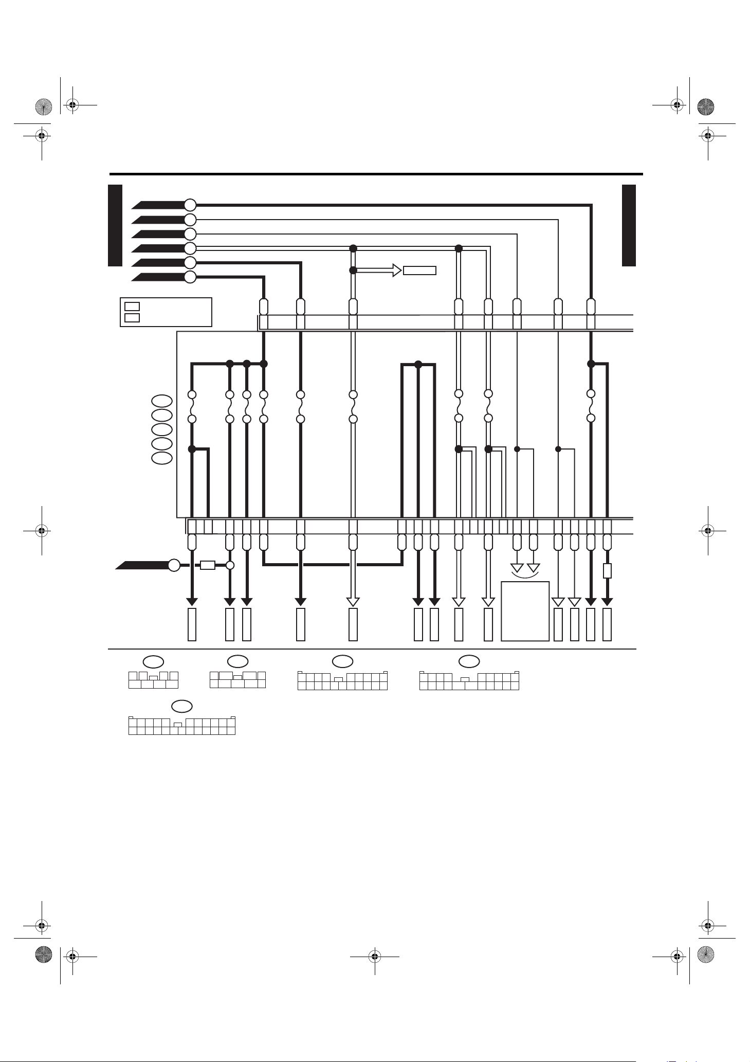
2. WITH PUSH BUTTON START
• Engine room side
P-SUP(P)-01
DAYTIME
RUNNING
LIGHT RELAY
A/C RELAY HOLDER (3.6 L MODEL)
MAIN FAN
FRONT
DAYTIME
RUNNING
LIGHT RELAY
SUB FAN
RELAY
A/C RELAY HOLDER (2.5 L MODEL)
MAIN FAN
RELAY 1
RELAY
HORN
RELAY
12
12
No. 38
No. 20
12
No. 39
12
TA IL & I L LU MI
BAT
MAIN
SBF
ALT
SBF-13
MAIN
FAN
RELAY
2
12
No. 33
No. 32
SBF-9
SBF-3
12
SBF-4
12
RELAY
2
1
3
4
No. 34
12
No. 35
12
SBF-11 SBF-10
SBF-12
12
No. 37
21
12
21
12
21
No. 11
21
No. 12
21
No. 13
21
No. 14
21
No. 15
21
No. 16
21
No. 17
21
No. 18
21
No. 19
21
4
2
3
1
F. F O G
RELAY
2
BRAKE
RELAY
4
532
1
SBF-2
POWER WINDOW
No. 27
12
No. 28
12
No. 29
12
WIPER
RELAY
3
4
2
1
1
3
4
H/L LO
RELAY
2
4
3
1
12
RELAY
2
1
4
12
12
No. 24
No. 23
M/B
No. 1
1
No. 10
R. DEF
RELAY
1
3
21
12
No. 2
12
No. 21
12
No. 22
12
4
2
No. 36
SBF-5
12
SBF-6
12
SBF-7
12
SBF-8
12
12
No. 25
21
No. 26
21
H/L HI
RELAY
4
3
2
3
No. 3
21
No. 4
21
No. 5
21
No. 6
21
No. 7
21
No. 8
21
No. 9
21
21
21
No. 31
No. 30
P-SUP(P)-01
WI-36114
WI-24

14LE_US_EN.book 25 ページ 2013年4月9日 火曜日 午後3時12分
Power Supply Circuit
• Passenger room side
No. 20
No. 27
P-SUP(P)-02
No. 28
No. 29
No. 30
No. 31
No. 32
No. 33
No. 21
No. 22
No. 23
No. 24
No. 25
No. 26
F/B FRONT SIDE
No. 13
No. 14
No. 15
No. 16
No. 17
No. 18
No. 19
F/B BACK SIDE
No. 6
No. 7
No. 8
No. 9
No. 10
No. 11
No. 12
WIRING SYSTEM
P-SUP(P)-02
No. 1
No. 2
No. 3
No. 4
No. 5
ACCES SORY
RELAY
SELF
SHUT
RELAY
IG
RELAY 2 IG RELAY 1
MAIN
RELAY
(
PUSH BUTTON
STARTER
RELAY
START
)
IG
RELAY
RELAY HOLDER
A/F, OXY GEN
STARTER
CUT
RELAY
STARTER
RELAY
SENSOR
RELAY
ELECTRIC
THROTTLE
CONTROL
RELAY
INHIBITOR
RELAY
ACCESSORY
RELAY
IG 2
RELAY
ACC
RELAY
FUEL
PUMP
RELAY
BACK LAMP
RELAY
IG
RELAY 2 IG RELAY 1
STARTER
RELAY
(
PUSH BUTTON
START
STARTER
CUT
RELAY
STARTER
)
RELAY
RELAY HOLDER (2.5 L MODEL
)
RELAY HOLDER (3.6 L MODEL
)
WI-36115
WI-25

14LE_US_EN.book 26 ページ 2013年4月9日 火曜日 午後3時12分
Power Supply Circuit
WIRING SYSTEM
P-SUP(P)-03
B515
GENERATOR
BATTERY
W
2
B471
W
WRWR
M/B
W
MAIN SBF 120A
1
1
No. 2 7.5A
21
SBF-8 50A
SBF-6 40A
2
2
No. 9 30A
1
No. 6 25A
2
1
1
SBF-7 50A
2
2
: 2.5 L MODEL
25
: WITH EyeSight
ES
1
No. 5 15A
2
1
No. 4 15A
No. 8 25A
2
25
1
No. 7 25A
2
25
1
1
SBF-5 40A
2
2
REAR DEFOGGER RELAY
1
P-SUP(P)-08
A
P-SUP(P)-04
B
GB
GOr
P-SUP(P)-03
P-SUP(P)-04
C
P-SUP(P)-04
D
1
1
2
4
1
WIPER RELAY
1
3
2
3
4
1
BATTERY CURRENT
CURRENT FROM IGNITION SWITCH
"IG" TERMINAL
CURRENT FROM IGNITION SWITCH
"ACC" TERMINAL
OTHER
(GREEN)
B471
2
31
B478
3
No. 39 10A
21
L
421
5
WR
MB-1
RY
MB-2
RB
MB-3
G
GL
MB-4
G
ES
LW
MB-46
Y
MB-6
RW
MB-7
No. 22 25A
W
MB-5
2
RL
MB-8
No. 29 30A
VG
MB-9
No. 28 10A
2
GW
MB-10
No. 27 15A
2
GB
MB-11
2
GMB-12
B
P-SUP(P)-06
E
P-SUP(P)-07
F
P-SUP(P)-08
G
P-SUP(P)-06
H
B
J/C
2
B478
REF. TO GND
[GND-02]
WI-36116
WI-26

14LE_US_EN.book 27 ページ 2013年4月9日 火曜日 午後3時12分
Power Supply Circuit
P-SUP(P)-03
P-SUP(P)-04
B
C K
GB
GB
WIRING SYSTEM
P-SUP(P)-06
I
P-SUP(P)-07
J
P-SUP(P)-05P-SUP(P)-03
P-SUP(P)-04
P-SUP(P)-03
No. 31 10A
1
2
LR
D
FRONT FOG LIGHT RELAY
1
3
1
No. 30 10A
2
L
2
4
VY
1
No. 10 20A
2
LR
1
No. 19 20A
2
WR
1
No. 11 20A
2
WL
1
SBF-9 30A
SBF-11 30A
2
W
1
1
SBF-10 30A
2
2
BW
WG
GR
GR
1
2
3
POWER WINDOW RELAY
1
2
4
GR
BW
GR
B
B517B516
TAIL & ILLUMINATION RELAY
1
No. 35 10A
2
BL
1
3
1
No. 34 10A
2
V
2
4
LY
BW
HEADLIGHT RELAY HI
1
No. 26 10A
2
RL
1
3
1
No. 25 10A
2
RG
2
4
L
LY
HEADLIGHT RELAY LO
1
No. 24 15A
2
BrR
1
3
1
No. 23 15A
2
BrW
2
4
LY
LG
P-SUP(P)-06
L
P-SUP(P)-06
M
P-SUP(P)-06
N
P-SUP(P)-05
O
MB-13
B517
12
MB-14
MB-15
MB-17
MB-18
MB-19
MB-20
WI-27
MB-22
MB-23
MB-24
MB-25
MB-26
MB-27
MB-28
MB-29
MB-30
MB-31
WI-36117

14LE_US_EN.book 28 ページ 2013年4月9日 火曜日 午後3時12分
Power Supply Circuit
WIRING SYSTEM
P-SUP(P)-05
P-SUP(P)-04
K
WL
BrW
3
5
BRAKE RELAY
1
ES
ES
ES
RL
2
4
HORN RELAY
1
No. 32 7.5A
No. 33 7.5A
2
REF. TO EyeSight SYSTEM
[E/S(NA)-04]
[E/S(H6)-04]
H6
1
2
3
4
1
2
1
No. 18 15A
SBF-2 80A
2
1
No. 16 15A
2
1
No. 15 15A
2
REF. TO ENGINE
ELECTRICAL SYSTEM
[E/G(NAP)-05]
[E/G(H6P)-14]
1
1
1
No. 14 15A
No. 13 15A
2
2
2
1
No. 20 20A
No. 12 7.5A
2
1
No. 17 10A
2
P
AT
CVT
1
No. 1 20A
2
1
1
No. 36
2
2
DELIVERY (TEST) MODE FUSE
W
1
No. 38 7.5A
2
P-SUP(P)-06
P
REF. TO CVT CONTROL
SYSTEM
[CVT-05]
: WITH EyeSight
ES
: 3.6 L MODEL
H6
P-SUP(P)-05
P-SUP(P)-04
B491
O
J/C
REF. TO
GND
[GND-02]
Br
ES
B
1
REF. TO EyeSight
SYSTEM
B483
B491
3
B
ES
[E/S(H6)-04]
B
3
[E/S(NA)-04]
REF. TO
GND
[GND-01]
421
5
J/C
B483
BG
RG
MB-32
R
MB-33
MB-34
W
MB-35
WB
MB-36
W
MB-37
R
MB-38
G
MB-39
L
MB-40
WG
MB-41
W
MB-42
WR
MB-43
BY
WR
MB-44
REF. TO ENGINE
ELECTRICAL SYSTEM
[E/G(NAP)-05]
GY
[E/G(H6P)-14]
REF. TO CVT
CONTROL SYSTEM
[CVT-05]
WI-36118
WI-28
14LE_US_EN.book 29 ページ 2013年4月9日 火曜日 午後3時12分
Power Supply Circuit
WIRING SYSTEM
P-SUP(P)-04
P-SUP(P)-03
P-SUP(P)-04
P-SUP(P)-04
P-SUP(P)-06
P-SUP(P)-04
P-SUP(P)-03
: WITH NAVIGATION
WN
: WITH EyeSight
ES
F/B
A:
i5
B:
i152
C:
B52
E:
B158
F:
B159
N
E
L
I
M
H
No. 1 15A
No. 8 15A
No. 9 15A
L
E6
No. 17 15A
BW
E4
No. 3 20A
GB
F6
No. 29 20A
FB-7
GB
E8
No. 2 20A
GB
E7
No. 15 20A
BL
C5
P-SUP(P)-06
G
F9
LR
C17
No. 14 10A
B4
C23
LOr
P-SUP(P)-05
E:
152
12 13 14 15 16 17 18 19 20 21 22 23 24
P
B158
34
678
3412 89
567
ES
FB-1
12 43
596
B52C:
F:
10 11
E1
WL
FB-2
B159
78
E3
C15
LB
LW
FB-3
(BROWN)
A9
WG
FB-5
A:
1234 56789
10 11 12 13 14 15 16 17 18 19 20
C2
G
FB-8
i5
E2
LW
A4
LW
FB-9
12032
B13
LB
FB-10
B:
4
14
13121110 1716
A7
GY
FB-13
i152
15
B6
576
A13
GW
FB-14
18
B2
A11
BL
REF. TO
CLEARANCE
98
19
B10
BL
LIGHT &
ILLUMINATION
LIGHT SYSTEM
[ILLUMI-02]
F5
GOr
FB-15
B15
G
FB-16
C4
B12
L
GW
WN
FB-41
FB-42
WI-36119
WI-29

14LE_US_EN.book 30 ページ 2013年4月9日 火曜日 午後3時12分
Power Supply Circuit
WIRING SYSTEM
P-SUP(P)-04
P-SUP(P)-03
J
F
P-SUP(P)-07
: TERMINAL No. OPTIONAL ARRANGEMENT
1
*
7
2
4
B
W
Sb
1
*
1
*
B
B
J/C
1
B491
REF. TO GND
[GND-02]
5
B
1
*
J/C
i82
REF. TO GND
[GND-04]
PUSH
BUTTON
IGNITION
SWITCH
i150
B36
i1
W
C28
Sb
C30
B
25
27
L
38
R
R
C4
W
23
ACCE SSORY
RELAY
(
PUSH
BUTTON
)
START
B225 B225
24
Y
i242C:B572A:
B
34
35
GrR
B36
39
i1
Y
Y
C6
KEYLESS ACCESS CM
W
33 32
G
IG
RELAY 1
(
PUSH
BUTTON
START
B575
B576
B
3031
)
1
VLR
V
A9
W
29 28
L
IG
RELAY 2
(
PUSH
BUTTON
START
B225
P-SUP(P)-08
P
W
GB
3938
STARTER RELAY
(
PUSH BUTTON
)
START
B225
37 36
B
B
B
B
1820
STARTER
CUT
WR
WR
B34
19 22
WB
RELAY
B225
P-SUP(P)-08
Q
P-SUP(P)-08
R
P-SUP(P)-08
S
P-SUP(P)-08
T
)
ECM
B:
B135
P-SUP(P)-07
3
10 11 12 13 14 15
98
202821 22 23
30
29
421
B:
5
B135
3231
B575
12345
6789
5672134
16
17 18 19
2524
26 27
33 34 35
i82
132
6
3
24
5
25
27
987
6
28262423
29
10
17
5
4
121110
B225
8
12
10 11
13
9
34
30
32 33
35
31
RELAY HOLDER
i150B491
342156
9108
14 15
36 37
13 1411
12
18
16
19 21 22
17
20
40
38
41 43 44
39
42
7
WI-30
A:
B572
12
10
9
11 123413 145615 167817 18
21
34
5678 9
16 1714
15
13
29
30
28
4443
45
314632
19
334834
47
49
123 456
789
19 20 21 22 23 24 25 26 27 28 29 30
B36
20 21
22
23
355036
37
38
51
52
53
C:
i242
10 11 12 13 14 15 16 17 18
12
25
2618
27
40
41
42
55
56 57
24
39
54
10 11
WI-36120
14LE_US_EN.book 31 ページ 2013年4月9日 火曜日 午後3時12分
Power Supply Circuit
WIRING SYSTEM
P-SUP(P)-07
P-SUP(P)-07
P-SUP(P)-08
P-SUP(P)-07
P-SUP(P)-07
P-SUP(P)-03
Q
R
S
T
G
No. 7 7.5A
H6
: 3.6 L MODEL
H6
No. 22 15A
No. 33 7.5A
L
WB
F2
F3
F/B
A:
i5
B:
i152
C:
B52
D:
B152
E:
B158
F:
No. 21 7.5A
B159
G:
AB35
H:
i193
Y
G
F7
E5
IG 2 RELAY
ACCESSORY RELAY
No. 6 7.5A
No. 13 20A
No. 20 10A
No. 24 15A
No. 31 7.5A
No. 4 7.5A
G
F8
No. 32 7.5A
No. 26 7.5A
No. 25 15A
No. 11 7.5A
No. 5 7.5A
No. 18 7.5A
No. 12 15A
No. 19 7.5A
P-SUP(P)-08
P-SUP(P)-07
P-SUP(P)-03
G: H:
AB35
12
P
A
A:
1234 56789
10 11 12 13 14 15 16 17 18 19 20
B11
WL
FB-17
i5
C19
WL
FB-18
i193
12
D6
A10
Y
FB-19
B14
Y
FB-20
A19
YV
FB-21
A17
YR
FB-22
B491
12032
C7A1D7
YR
YR
FB-25
FB-24
421
3
5
4
13121110 1716
B:
A5
GY
FB-26
14
i152
GOr
FB-38
(GRAY)(BLACK) (BROWN)
9
43
10
C1
GOr
FB-39
D1A3D8
WL
H6
ST-1
B
B
J/C
1
B491
REF. TO
GND
ST-2
[GND-02]
D:
10 11
D2
Gr
FB-43
B152
21
D3
GY
FB-37
8765
A6
D9
C8
B18
GY
FB-27
E:
152
576
15
OrG
FB-28
B158
34
678
98
19
18
C16
A20A8C24
GL
BrW
FB-30
FB-29
H1
G
GR
FB-32
FB-31
F:
12 43
596
3412 89
12 13 14 15 16 17 18 19 20 21 22 23 24
H2
D4
Br
FB-33
B52
GY
FB-40
G2
GY
FB-34
G1
B159
78
C:
567
C11
GB
FB-35
WI-36121
WI-31

14LE_US_EN.book 32 ページ 2013年4月9日 火曜日 午後3時12分
Power Supply Circuit
WIRING SYSTEM
No. Load
MB-1 VDC CM
MB-2 VDC CM
MB-3 Audio connector
Audio
Audio amplifier
MB-4 Blower motor relay
MB-5 IG relay 2 (push button start)
IG relay 1 (push button start)
Accessory relay (push button start)
MB-6 Main fan relay 1
MB-7 Sub fan relay
MB-8 Mirror heater relay
Rear defogger
MB-9 Body integrated unit
MB-10 Front wiper motor
Combination switch (wiper)
MB-11 Front washer motor
MB-12 Rear washer motor
MB-13 Front fog light RH
MB-14 Front fog light LH
MB-15 Body integrated unit
MB-17 Body integrated unit
MB-18 Sunroof motor assembly
MB-19 EPB CM
MB-20 Power seat LH
Power seat RH
Power seat (with seat position memory)
MB-22 Front combination light LH (clearance light)
Front combination light RH (clearance light)
F/B
MB-23 Satellite switch illumination
Stereo camera cover (with EyeSight)
Steering switch illumination
AT s el e c t l ev e r i l l um i n at i o n
Illumination control switch
Remote control mirror switch
Lower cover switch
Glove box light
Hill hold switch
Audio
Navigation unit
Seat heater switch (power seat)
Shower light
A/C control panel
EPB control switch
MB-24 Body integrated unit
Daytime running light relay
MB-25 Body integrated unit
MB-26 Front combination light RH (headlight)
MB-27 Front combination light LH (headlight)
No. Load
MB-28 Body integrated unit
MB-29 Front combination light RH (headlight)
MB-30 Front combination light LH (headlight)
MB-31 Body integrated unit
MB-32 Horn
MB-33 Horn
MB-34 Body integrated unit
Horn switch
MB-35 Main fan relay
MB-36 Body integrated unit
Tu r n s ig na l an d h azar d u nit
MB-37 Main relay
MB-38 A/F, oxygen sensor relay
MB-39 IG relay
MB-40 Electronic throttle control relay
MB-41 Fuel pump relay
MB-42 ECM
Data link connector
MB-43 TCM
MB-44 Self shut relay
TCM
MB-46 Stereo camera
ST-1 Inhibitor relay
ST-2 Starter relay
FB-1 Trailer connector
FB-2 Stop light and brake switch
Stop light register
Brake relay
FB-3 Seat heater relay
FB-5 Power window main switch
FB-7 Power window circuit breaker
FB-8 Front power window sub-switch
FB-9 Wiper deicer relay
FB-10 Mirror heater relay
FB-13 Rear power window sub-switch LH
FB-14 Rear power window sub-switch RH
FB-15 Body integrated unit
FB-16 Rear wiper motor
FB-17 Combination meter
Body integrated unit
Impact sensor
EPB control switch
A/C CM
FB-18 Keyless access CM
Steering lock CM
FB-19 Remote control mirror switch
Seat heater relay
Rearview mirror (without home link)
FB-20 Rear accessory power supply socket
FB-21 Front accessory power supply socket
WI-32
 Loading...