


asieps_tobira.book 3 ページ 2012年1月17日 火曜日 午後6時33分
Basic Diagnostic Procedure
WIRING SYSTEM
1. Basic Diagnostic Procedure
A: BASIC PROCEDURES
1. GENERAL DESCRIPTION
The most important purpose of diagnostics is to
quickly determine which part is malfunctioning, to
save time and labor.
2. IDENTIFICATION OF TROUBLE SYMPTOM
Determine what the problem is based on the symptom.
3. PROBABLE CAUSE OF TROUBLE
Look at the wiring diagram and check the system’s
circuit. Then check the switch, relay, fuse, ground,
etc.
4. LOCATION AND REPAIR OF TROUBLE
1) Using the diagnostics, narrow down the causes.
2) If necessary, use a voltmeter, ohmmeter, etc.
3) Before replacing certain component parts
(switch, relay, etc.), check the power supply,
ground, for open wiring harness, poor connectors,
etc. If no problem is encountered, check the component parts.
5. SYSTEM OPERATION CHECK
After repairing, ensure that the system operates
properly.
B: BASIC INSPECTION
1. VOLTAGE MEASUREMENT
1) Using a voltmeter, connect the negative lead to a
good ground point or negative battery terminal and
the positive lead to the connector or component terminal.
2) Contact the positive lead of the voltmeter on
connector (A). The voltmeter will indicate a voltage.
3) Shift the positive lead to connector (B). The voltmeter will indicate no voltage.
To power
supply
Fuse
Switch
Light
5) The circuit is in good order. If a problem such as
a light failing to illuminate occurs, use the procedures outlined above to track down the malfunction.
2. CIRCUIT CONTINUITY CHECKS
1) Disconnect the battery terminal or connector so
there is no voltage between the check points.
Contact the two leads of an ohmmeter to each of
the check points.
If the circuit has diodes, reverse the two leads and
check again.
2) Use an ohmmeter to check for diode continuity.
When contacting the negative lead to the diode
positive side and the positive lead to the negative
side, there should be continuity.
When contacting the two leads in reverse, there
should be no continuity.
Continuity No continuity
WI-02740
3) The symbol “ — ” indicates that continuity
exists between two points or terminals. For example, when a switch position is at “3”, continuity exists among terminals 1, 3 and 6, as shown in the
table below.
Te rm ina l
Switch Position
OFF
1
2
3
4
1
234
56
WI-02741
(A)
(B)
V
WI-02739
4) With the test set-up held as it is, turn the switch
to ON. The voltmeter will indicate a voltage and, at
the same time, the light will illuminate.
WI-3
asieps_tobira.book 4 ページ 2012年1月17日 火曜日 午後6時33分
Basic Diagnostic Procedure
WIRING SYSTEM
3. HOW TO DETERMINE AN OPEN CIRCUIT
1) WITH VOLTMETER:
An open circuit is determined by measuring the
voltage between respective connectors and ground
using a voltmeter, starting with the connector closest to the power supply. The power supply must be
turned ON so that current flows in the circuit. If voltage is not present between a particular connector
and ground, the circuit between that connector and
the previous connector is open.
Open circuit
WI-09860
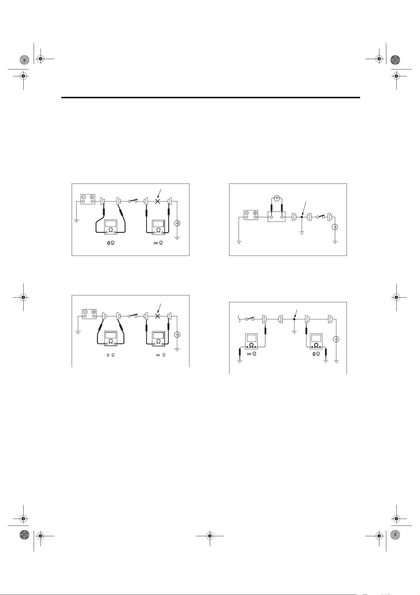
2) WITH OHMMETER:
Disconnect all connectors affected, and check continuity in the wiring between adjacent connectors.
When the ohmmeter indicates “infinite”, the wiring
is open.
Open circuit
4. HOW TO DETERMINE A SHORT CIRCUIT
1) WITH TEST LIGHT:
Connect a test light (rated at approx. 3 watts) in
place of the blown fuse and allow current to flow
through the circuit. Disconnect one connector at a
time from the circuit. Starting with the one located
farthest from the power supply. If the test light goes
out when a connector is disconnected, the wiring
between that connector and the next connector
(farther from the power supply) is shorted.
Test light
Shorted wiring
Fuse holder
WI-02744
2) WITH OHMMETER:
Disconnect all affected connectors, and check continuity between each connector and ground. When
the ohmmeter indicates continuity between a particular connector and a ground, that connector is
shorted.
Shorted connector
WI-02743
WI-02745
WI-4

asieps_tobira.book 5 ページ 2012年1月17日 火曜日 午後6時33分
Basic Diagnostic Procedure
C: HOW TO READ WIRING DIA-
GRAMS
1. WIRING DIAGRAM
The wiring diagram of each system is illustrated so
that you can understand the path through which the
electric current flows from the battery.
Sketches and codes are used in the diagrams.
They should read as follows:
•Each connector and its terminal position are indicated by a sketch of the connector in a disconnected state which is viewed from the front.
2
1
3
4
WIRING SYSTEM
4
Viewed from this direction
WI-02746
•The number of poles or pins, presence of a lock
are indicated in the sketch of each connector. In the
sketch, the highest pole number refers to the number of poles which the connector has. For example,
the sketch of the connector shown in figure indicates the connector has 9 poles.
Connector used in vehicle
Double frames
Indicates the number of poles.
Sketch Symbol Number of poles
Indicates a lock
is included.
43
98
7
1
2
65
Connector shown in wiring diagram
Numbered in order from upper
right to lower left
Indicates a lock is included.
12
56
Single frame
7
4
3
9
8
Numbered in order from upper
left to lower right
WI-02747
WI-5

asieps_tobira.book 6 ページ 2012年1月17日 火曜日 午後6時33分
Basic Diagnostic Procedure
WIRING SYSTEM
•When one set of connectors is viewed from the
front side, the pole numbers of one connector are
symmetrical to those of the other. When these two
connectors are connected as a unit, the poles
which have the same number are joined.
1
2
3
6
5
44
3
6
2
5
1
WI-00107
•WIRING DIAGRAM:
The connectors are numbered along with the number of poles, external colors, and mating connections in the accompanying list.
•The sketch of each connector in the wiring diagram usually shows the (A) side of the connector.
The relationship between the wire color, terminal
number and connector is described in the figure.
•The following color codes are used to indicate
the colors of the wires.
Color code Color
LBlue
BBlack
YYellow
GGreen
RRed
WWhite
Br Brown
Lg Light green
Gr Gray
PPink
Or Orange
Sb Light blue
V Violet
SA Sealed (Inner)
SB Sealed (Outer)
YG
NOTE:
A wire which runs in one direction from a connector
terminal sometimes may have a different color from
that which runs in the other direction from that terminal.
i2
BR
1
RW
3
Wire color :
BR (No. 1 terminal)
RW (No. 3 terminal)
(A)
i2F4
12
34
WI-02748
•In the wiring diagram, connectors which have no
terminal number refer to one-pole types. Sketches
of these connectors are omitted intentionally.
BB
SA
SB10
YL9
YG8
SB22
SA20
SB
YL
SB
YL 2
YG 1
SA 1
WI-00110
B15F10
WI-00109
WI-6
asieps_tobira.book 7 ページ 2012年1月17日 火曜日 午後6時33分
Basic Diagnostic Procedure
WIRING SYSTEM
•The wire color code, which consists of two letters
(or three letters including Br or Lg), indicates the
standard color (base color of the wire covering) by
its first letter and the stripe marking by its second
letter.
YB
BlackMarking color :
Reference color : Yellow
WI-03797
•The table lists the nominal sectional areas and
allowable currents of the wires.
CAUTION:
When replacing or repairing a wire, be sure to
use the same size and type of the wire which
was originally used.
NOTE:
•The allowable current in the table indicates the
tolerable amperage of each wire at an ambient
temperature of 40°C (104°F).
•The allowable current changes with ambient
temperature. Also, it changes if a bundle of more
than two wires is used.
Nominal
sectional area
0.3 7/0.26 1.8 7
0.5 7/0.32 2.2 (or 2.0) 12
0.75 30/0.18 2.6 (or 2.4) 16
0.85 11/0.32 2.4 (or 2.2) 16
1.25 16/0.32 2.7 (or 2.5) 21
226/0.323.1 (or 2.9)28
341/0.323.8 (or 3.6)38
565/0.324.6 (or 4.4)51
850/0.455.5 67
mm
No. of
strands/
strand
2
diameter
Outside
diameter of
wiring
mm
Allowable
current
Amps/
40°C (104°F)
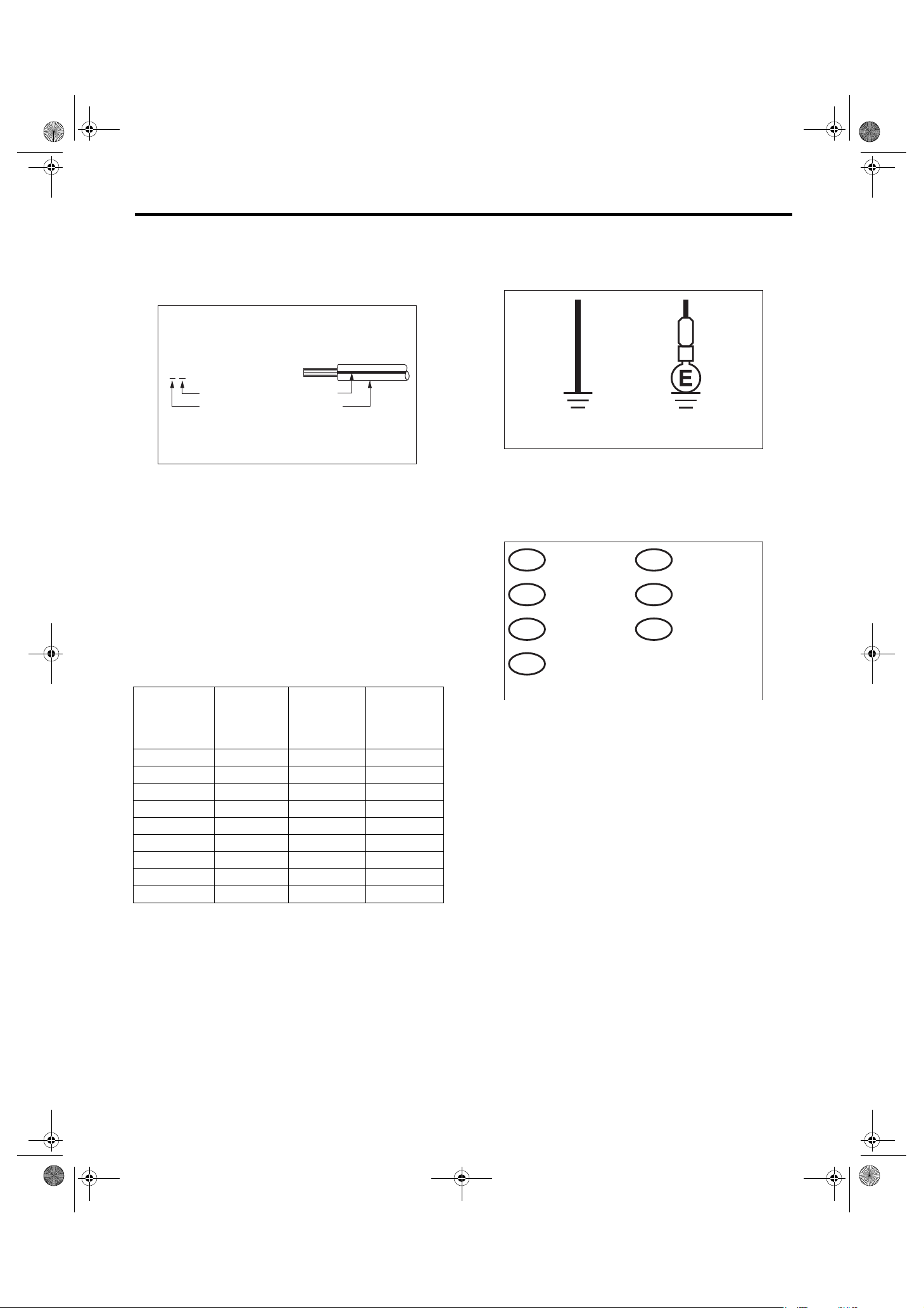
•Each unit is either directly grounded to the body
or indirectly grounds through a harness ground terminal. Different symbols are used in the wiring diagram to identify the two grounding systems.
B
Direct ground Indirect terminal
ground
WI-02750
•The ground points shown in the wiring diagram
refer to the following:
NOTE:
All wiring harnesses are provided with a ground
point which should be securely connected.
: ABS GROUND
GA
: AIRBAG GROUND
GAB
: BODY GROUND
GB
: REAR DEFOGGER GROUND
GD
: ENGINE GROUND
GE
: RADIO GROUND
GR
: VDC GROUND
GV
WI-03791
WI-7

asieps_tobira.book 8 ページ 2012年1月17日 火曜日 午後6時33分
Basic Diagnostic Procedure
WIRING SYSTEM
•Relays are classified as normally-open or normally-closed.
The normally-closed relay has one or more contacts. The wiring diagram shows the relay mode when the energizing circuit is OFF.
Relay type
Normally-open type
Normally-closed type
4-pole
6-pole
4-pole
Energizing circuit OFF
Energizing circuit ON
Mixed type
Key to s ymbols:
6-pole
: Curren t flows.
: Curren t does n ot flow.
WI-02752
WI-8
asieps_tobira.book 9 ページ 2012年1月17日 火曜日 午後6時33分
Basic Diagnostic Procedure
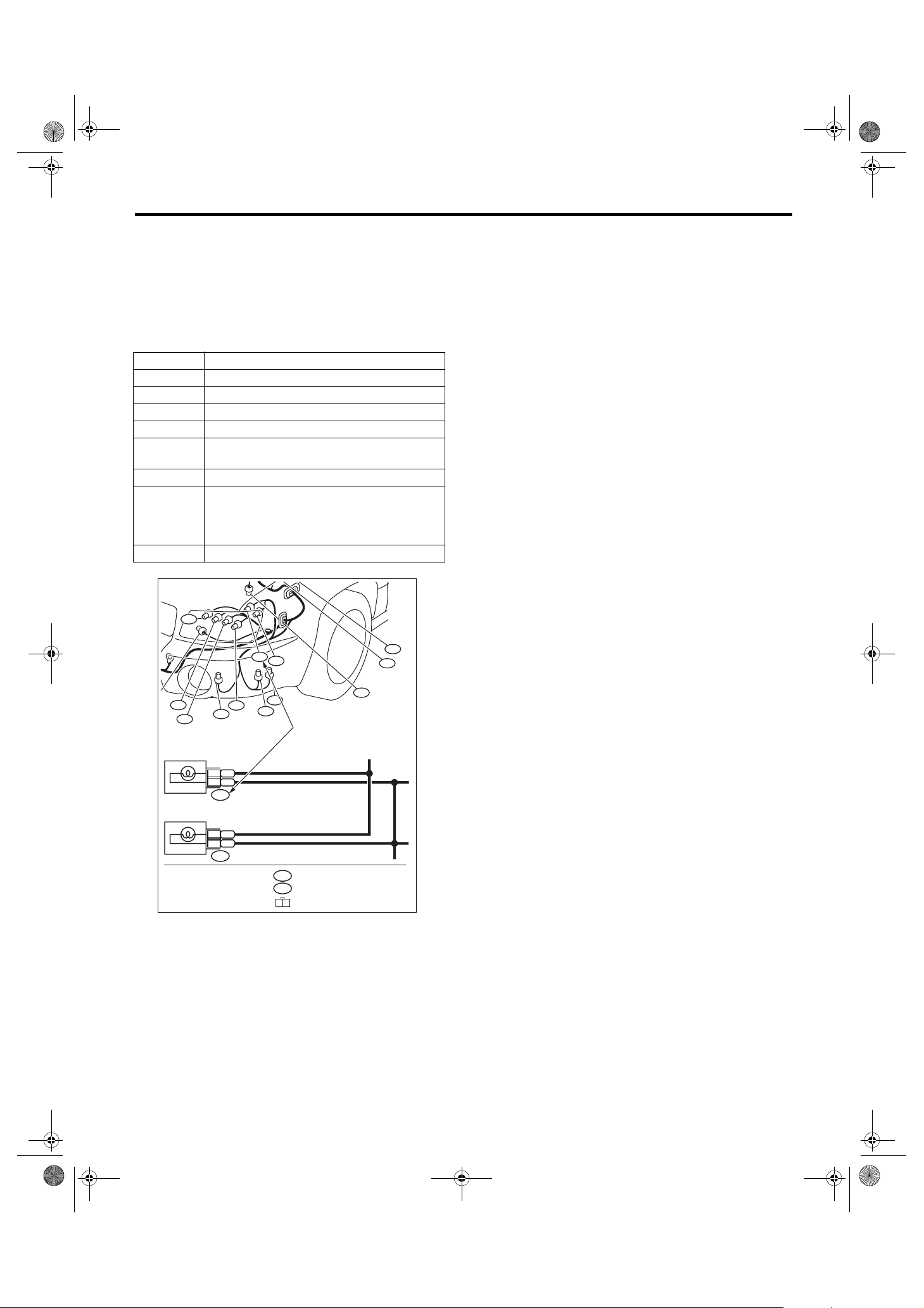
•Each connector number shown in the wiring diagram corresponds to that in the wiring harness. The
location of each connector in the actual vehicle is
determined by reading the first character of the
connector (for example, a “F” for F8, “i” for i16, etc.)
and the type of wiring harness. The first character
of each connector number corresponds to the area
or system of the vehicle.
Symbol Wiring harness and cord
FFront wiring harness
BBulkhead wiring harness
EEngine wiring harness
TTransmission cord
D
iInstrument panel wiring harness
R
AB Airbag wiring harness
Door cord LH & RH, Rear gate cord
Rear door cord LH & RH, Rear defogger cord
Rear wiring harness,
Fuel tank cord,
Roof cord, Rear gate cord,
Rear defogger ground cord (Sedan model)
WIRING SYSTEM
F58
F23
F98
FRONT TURN SIGNAL
LIGHT LH (UPPER)
FRONT TURN SIGNAL
LIGHT LH (LOWER)
F19
F22
F100
F21
F47
F5
F27
F34
F96
Each connector number
shown in wiring diagram
corresponds to that in
BG2
B1
F19
BG3
B2
F22
the vehicle.
(GRAY)
F3
(GRAY)
F19
1 2
WI-02753
WI-9

asieps_tobira.book 10 ページ 2012年1月17日 火曜日 午後6時33分
Basic Diagnostic Procedure
WIRING SYSTEM
D: SYMBOLS IN WIRING DIAGRAMS
A number of symbols are used in each wiring diagram to easily identify parts or circuits.
Example
RELAY
SYMBOLS OF
WIRE
CONNECTION
AND CROSSING
SPECIFICATION
CLASSIFICATION
OR
: WITHOUT REAR DEFOGGER
: WITH REAR DEFOGGER
WR
DIODE
SBF-1 100A
HEADLIGHT
RELAY
RH
No.3 10A
3
F39
LR
H/L(2L)-01
HEADLIGHT LH
LOW
HEADLIGHT RH
LOW
DIMMER & PASSING
SWITCH
UP
LOW PASS
LIGHTING SWITCH
OFF
GROUND
DIODE
HF
HU
HL
HC
TC
EL
E
No.9 15A
7
LW
MB-11
HIGH
HIGH
MAIN FUSE BOX (M/B)
HEADLIGHT
RELAY
LH
No.8 15A
2
RL
MB-10
RL2
R1
YL3
F23
LW2
R1
YL3
F7
WROR
LY8
3
RY7
2
YB
17
B1716
16
LY
13 13
B71
YB1
RY2
B112
REF. TO GND-02
5
G
MB-10
M/B FUSE NO. 8
B
P-SUP-02
A
P-SUP-02
B
P-SUP-02
C
P-SUP-04
D
POWER SUPPLY
ROUTING
TO POWER SUPPLY ROUTING
MB-11
F/B FUSE NO. 11
M/B FUSE NO. 9
RL
LW
LW 4
LW
R3
R
YL
2
YL
F44
REF. TO FOG (H4)-01
REF. TO FOG (H6)-01
P
R4
PARKING
BRAKE
SWITCH
B61
SD SD
WG
REF. TO ST (MT)-01
REF. TO ST (AT)-01
WIRE TRACING
ON EXTENDED
WIRING DIAGRAMS
FB-16
MB-5
HEADLIGHT
(IG)
RELAY
LB
P P17
R3
P P7
R1
GR
F45
SMJ
B62
LB H1
LW B1
RA1
B36
SMJ
B99
WG
B97
No.1 20A
No.2 15A
3
2
R
LR
SMJ
SPECIFICATION
CLASSIFICATION
: SEDAN
SD
: WAGON
WG
FUSE No. & RATING
SBF-6 30A
SBF-3 50A
R 3
FUSE &
RELAY
BOX
(F/B)
A:
B51
B:
i5
C:
B52
D:
B152
E:
B158
F:
F40
G:
F41
G: (GRAY)
1 2 3
4 5 6 7
F7
F23
123
F41
BW 2
(BLACK)
(BLACK)
SBF-4 50A
F36 F38F68
W
LgB
D4
A2
A3
WR G4
FB-37
A:
1 2 3
4 5 6 7 8
1234
5 6 7 8
SBF-2 50A
1
L
C:
B52
B112
1 2
CONNECTOR-1
P-SUP-04
M
P-SUP-04
L
P-SUP-04
K
P-SUP-04
J
P-SUP-03
I
P-SUP-03
H
P-SUP-04
G
P-SUP-03
F
P-SUP-04
E
Or
BG
D7
D11
No.5 10A
BL G1
BR D10
BG G7
CONNECTOR-2
FB-35
FB-34
FB-36
B51
F44
CONNECTOR SKETCH
WI-03798
1. RELAY
A symbol used to indicate a relay.
2. CONNECTOR 1
The sketch of the connector indicates the one-pole
types.
3. WIRING CONNECTION
Some wiring diagrams are indicated in foldouts for
convenience. Wiring destinations are indicated
where necessary by corresponding symbols.
(When two pages are needed for clear indication)
4. FUSE NO. & RATING
The “FUSE No. & RATING” corresponds with that
used in the fuse box (main fuse box, fuse and joint
box).
5. CONNECTOR 2
•Each connector is indicated by a symbol.
• Each terminal number is indicated in the corresponding wiring diagram in an abbreviated form.
•For example, terminal number “G4” refers to No.
4 terminal of connector (G: F41) shown in the connector sketch.
WI-10
asieps_tobira.book 11 ページ 2012年1月17日 火曜日 午後6時33分
Basic Diagnostic Procedure
6. CONNECTOR SKETCH
•Each connector sketch clearly identifies the
shape and color of a connector as well as terminal
locations. Non-colored connectors are indicated in
white or natural color.
•When more than two types of connector number
are indicated in a connector sketch, it means that
the same type connectors are used.
7. GROUND
Each grounding point can be located easily by referring to the corresponding wiring harness.
8.DIODE
A symbol is used to indicate a diode.
9. WIRE TRACING ON EXTENDED WIRING
DIAGRAMS
For a wiring diagram extending over at least two
pages, a symbol (consisting of the same characters
with arrows), facilitates wire tracing from one page
to the next.
A ←→ A, B ←→ B
WIRING SYSTEM
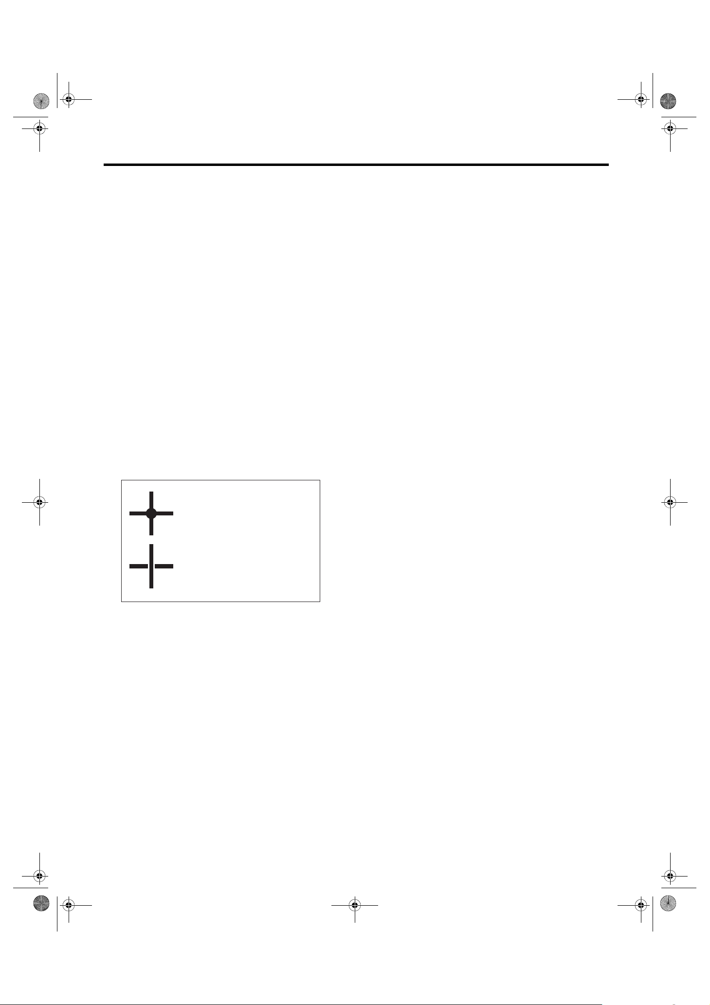
10.SYMBOLS OF WIRE CONNECTION AND
CROSSING
Symbol
Symbol Refers to wires which are
Refers to wires which are
connected and branched
at the dot point.
crossed but not connected.
WI-02755
11.POWER SUPPLY CIRCUIT
A symbol is used to indicate the power supply in
each wiring diagram.
“MB-5”, “MB-6”, etc., which are used as powersupply symbols throughout the text, correspond
with those shown in the “DC POWER SUPPLY
CIRCUIT” in the wiring diagram.
Accordingly, using the “DC POWER SUPPLY CIRCUIT” and wiring diagrams permits service personnel to understand the entire electrical arrangement
of a system.
12.CLASSIFICATION BY SPECIFICATION
When the wiring diagram differ according to vehicle
specifications, the specification difference is described by using abbreviations.
WI-11

asieps_tobira.book 12 ページ 2012年1月17日 火曜日 午後6時33分
Basic Diagnostic Procedure
WIRING SYSTEM
E: CONNECTOR SYMBOL IN WIRING HARNESS
A number of connector symbols are used in each wiring diagram to easily identify the wiring harness connectors.
Standard type: Female
Pole: From 1 to 8 Pole: From 9 to 20 Pole: More than 21
Standard type: Male
Water proof type: Female
Pole: From 1 to 8 Pole: From 9 to 20 Pole: More than 21
Water proof type: Male
WI-02756
WI-12

asieps_tobira.book 13 ページ 2012年1月17日 火曜日 午後6時33分
Basic Diagnostic Procedure
WIRING SYSTEM
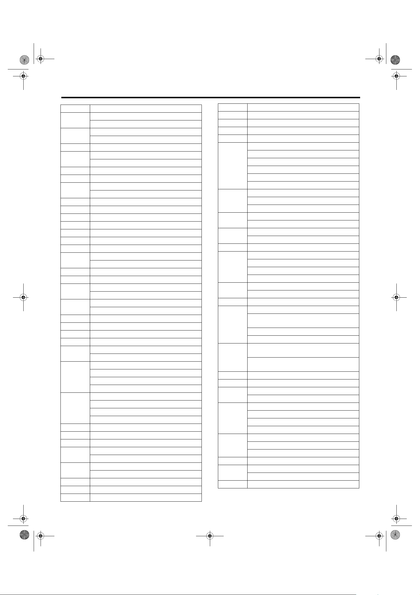
F: ABBREVIATION IN WIRING DIA-
GRAMS
Abbr. Full name
A/B Airbag
A/C Air Conditioner
A/F Air/Fuel (Air fuel ratio sensor)
ABS Anti-lock Brake System
ACC Accessory
AD Auto Down
ALT Generator
ASSY Assembly
AT A u to ma t i c Tr a ns m i ss i o n
AT F A ut o m at i c Tr a n sm i s si o n Fl u i d
AU Auto Up
AWD All Wheel Drive
B, BAT Battery
CAN Communication Area Network
CPU Central Processing Unit
DDrive Range
D, DN Do wn
EGround
EBD Electric Brake Distribution
ECM Engine Control Module
EGR Exhaust Gas Recirculation
ELR Emergency Locking Retractor
F/B Fuse & Relay Box
FL Front Left Hand
FL1.5 Fusible Link 1.5 mm
FR Front Right Hand
FWD Front Wheel Drive
GGravity (G sensor)
H/L Headlight
HI High
HID High Intensity Discharge
I/F Interface
IG Ignition
Illumi. Illumination
INT Intermittent
LCD Liquid Crystal Display
LH Left Hand
Lo Low
MMotor
M/B Main Fuse Box
MG Magnet
Mi Middle
MT Manual Transmission
MID Multi Information Display
MIST Wiper mist (One-touch)
MT Manual Transmission
NNeutral Range
2
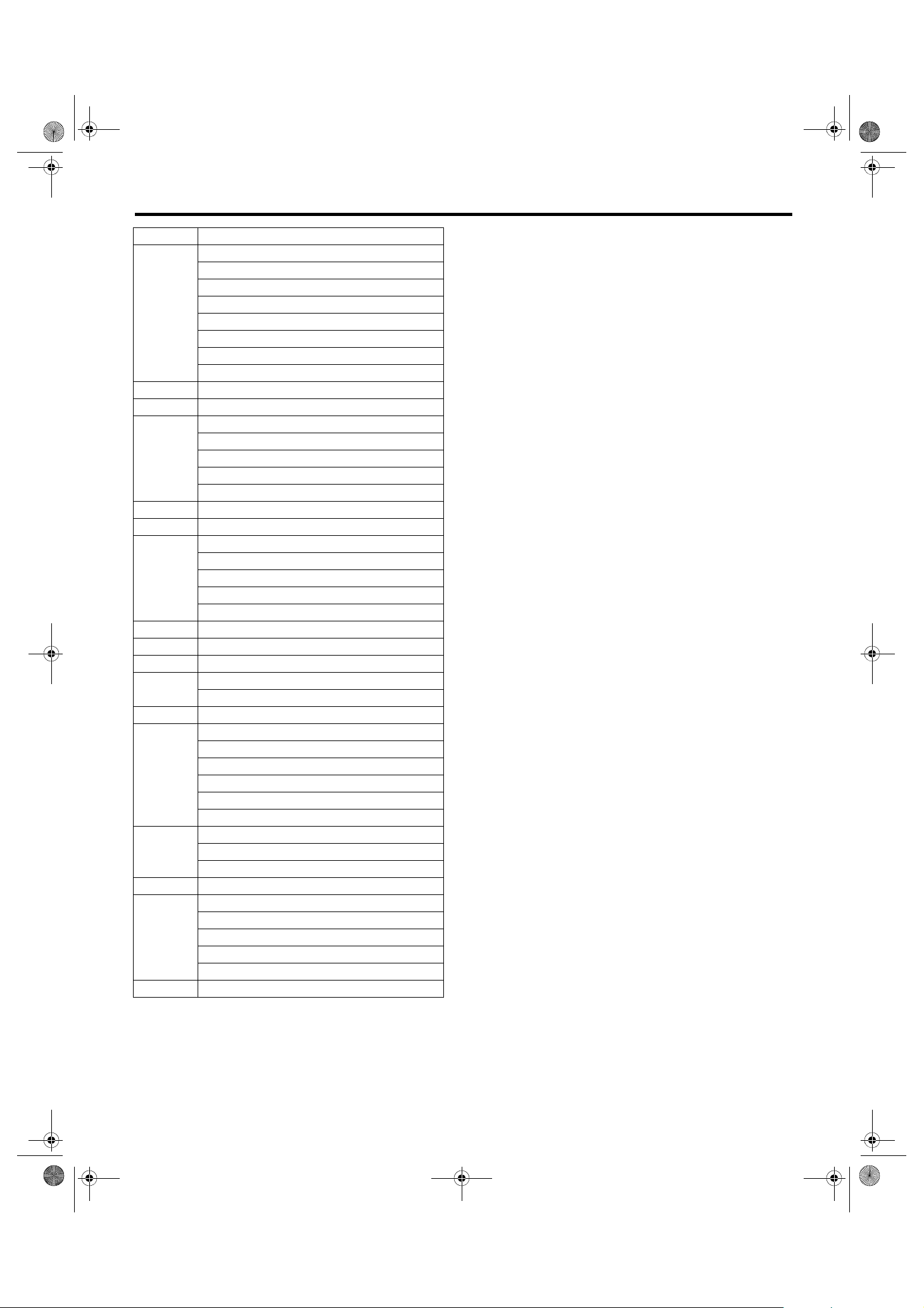
Abbr. Full name
NA Natural Aspiration
NAVI Navigation
OP Optional Parts or Open
PParking Range
PA S S P a s si n g
PCV Purge Control Valve
PWM Pulse Width Modulation
P-VIGN P-V Ignition relay
RReverse Range
R, RH Right Hand
RL Rear Left
RR Rear Right
SBF Slow Blow Fuse
S/S SPORT shift
ST Starter
SW Switch
TB Turbo
TCM AT Control Module
TGV Tumble Generator Valve
TPM Tire Pressure Monitor
TV Television
U, UP Up
VDC Vehicle Dynamics Control
VICS
WASH Washer
Vehi cle Information and Communi cati on
System
WI-13
asieps_tobira.book 14 ページ 2012年1月17日 火曜日 午後6時33分
Working Precautions
WIRING SYSTEM
2. Working Precautions
A: PRECAUTIONS WHEN WORKING
WITH THE PARTS MOUNTED ON
THE VEHICLE
1) When working under a vehicle which is jackedup, always be sure to use rigid rack.
2) The parking brake must always be applied during working. Also, in automatic transmission vehicles, keep the select lever set to the P (Parking)
range.
3) Be sure the workshop is properly ventilated
when running the engine. Further, be careful not to
touch the belt or fan while the engine is operating.
4) Be careful not to touch hot metal parts, especially the radiator and exhaust system immediately after the engine has been turned off.
B: PRECAUTIONS IN TROUBLE DI-
AGNOSIS AND REPAIR OF ELECTRIC PARTS
1) The battery cable must be disconnected from
the battery’s (–) terminal, and the ignition switch
must be set to the OFF position, unless otherwise
required by the diagnostics.
2) Securely fasten the wiring harness with clamps
and clips so that the harness does not interfere with
the body end parts or edges and bolts or screws.
3) When installing parts, be careful not to catch
them on the wiring harness.
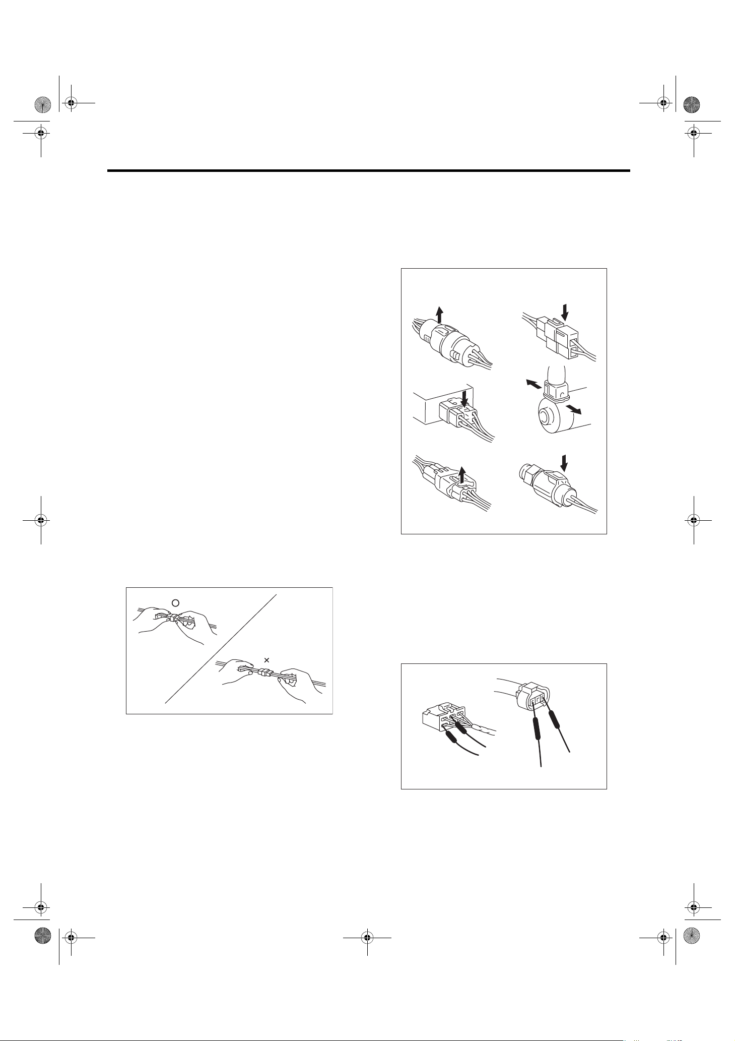
4) When disconnecting a connector, do not pull the
wires, but pull while holding the connector body.
5) Some connectors are provided with a lock. One
type of such a connector is disconnected by pushing the lock, and the other, by moving the lock up.
In either type the lock shape must be identified before attempting to disconnect the connector.
To connect, insert the connector until it snaps and
confirm that it is connected securely.
EXAMPLE
WI-02758
6) When checking continuity between connector
terminals, or measuring voltage across the terminal
and ground, always contact tester probe(s) on terminals from the wiring connection side. If the probe
is too thick to gain access to the terminal, use “mini”
test leads.
To check water-proof connectors (which are not
measurable from the wiring side), contact test
probes on the terminal side. Be careful not to bend
or damage the terminals.
WI-02757
WI-09366
7) Sensors, relays, electrical unit, etc., are sensitive to strong impacts.
Handle them with care so that they are not dropped
or mishandled.
WI-14

asieps_tobira.book 15 ページ 2012年1月17日 火曜日 午後6時33分
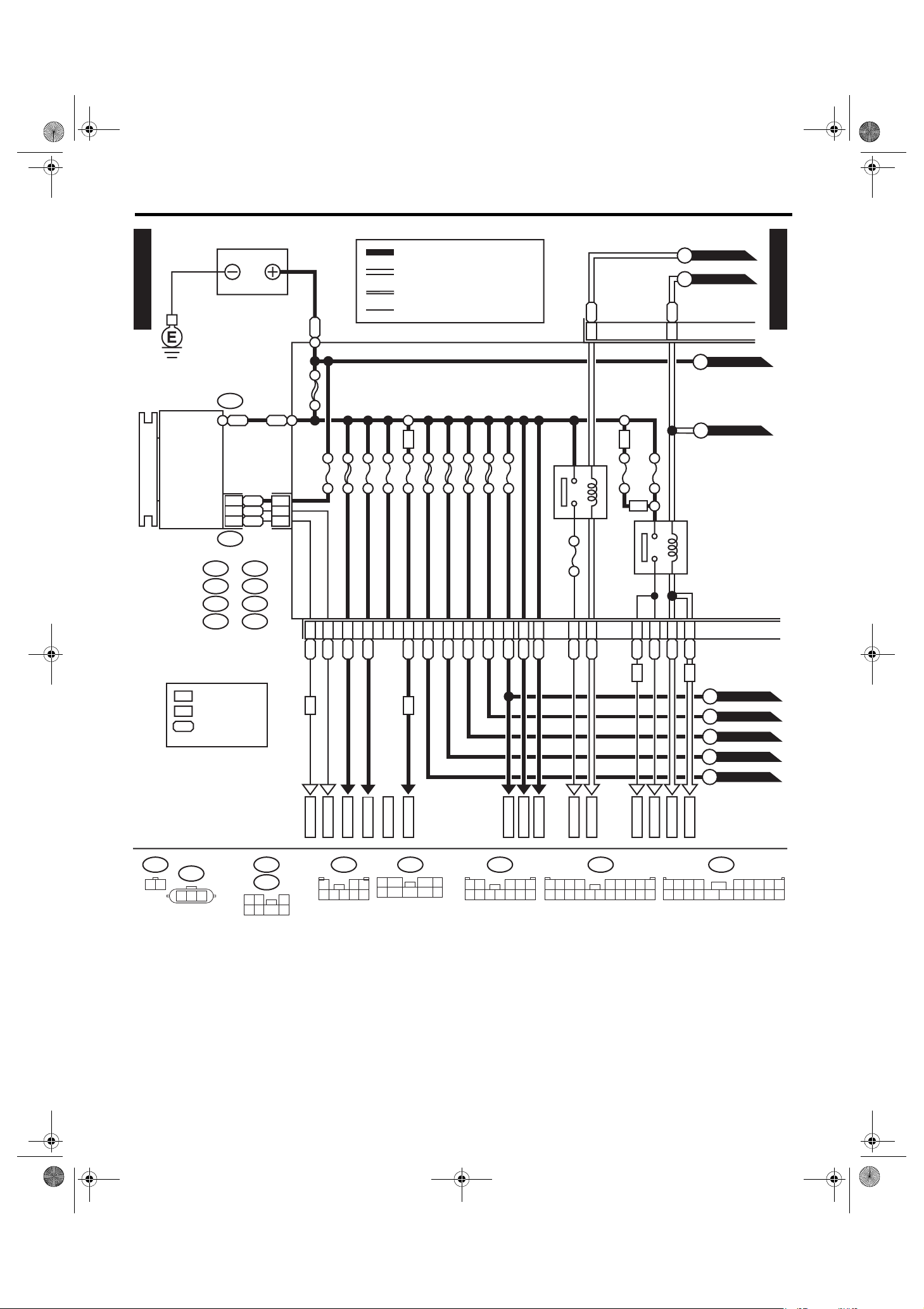
Power Supply Circuit
3. Power Supply Circuit
A: WIRING DIAGRAM
MAI N F USE BOX (M/ B)
WIRING SYSTEM
P-SUP-01
NO. 11
NO. 12
NO. 13
NO. 14
NO. 15
NO. 16
HORN
RELAY
NO. 9
NO. 10
SBF-8
R.DEF
RELAY
TAIL
RELAY
AIR CUT
RELAY 1
NO. 8
SBF-6 SBF-2
SBF-3
SBF-7
SECONDARY AIR FUSE & R ELAY BOX
No. 17
AIR
CUT
SBF-4
SBF-5
SBF-1
AIR CUT
RELAY 2
NO. 3
NO. 4
NO. 5
NO. 6
NO. 7
SBF-9
NO. 1
NO. 2
PUMP
RELAY
MAIN
SBF
AIR
MAIN
FAN
RELAY-1
H/L
RELAY
RH
H/L
RELAY
LH
P-SUP-01
NO. 27
NO. 28
NO. 29
NO. 30
NO. 31
NO. 32
NO. 33
FUS E & RELAY BOX (F/B)
NO. 20
NO. 13
NO. 21
NO. 14
NO. 22
NO. 15
NO. 23
NO. 16
NO. 24
NO. 17
NO. 25
NO. 18
NO. 26
NO. 19
NO. 6
NO. 7
NO. 8
NO. 9
NO. 10
NO. 11
NO. 12
WI-15
NO. 1
NO. 2
NO. 3
NO. 4
NO. 5
WI-13119
asieps_tobira.book 16 ページ 2012年1月17日 火曜日 午後6時33分
Power Supply Circuit
WIRING SYSTEM
P-SUP-02
GENERATOR
MAI N F USE BOX (M/ B)
A:
B:
B143
C:
B144D:B186
F37
F35
BATTERY
F25
2
1
3
F26
E:
F:
G:
H:
WR
BW
BR
F36
F70
B145
WW
A9
A7
A19
W
MAIN SBF 120A
SBF-1 50A
No. 16 7.5A
B1
B11
BR
WB
WR D7
No. 1 30A
RY D5
BATTERY CURRENT
CURRENT FROM IGNITION SWITCH
"IG" TERMINAL
CURRENT FROM IGNITION SWITCH
"ACC" TERMINAL
OTHER CURRENTS
H4
No. 3 25A
No. 5 20A
D1
SBF-2 50A
RW E3
SBF-3 50A
L D8
R D6
SBF-6 50A
W D2
No. 8 20A
SBF-8 50A
G D3
LR D9
P-SUP-05
A
P-SUP-05
B
P-SUP-02
No. 4 25A
E5
E6
1
LR
GB
B19
P-SUP-03
C
P-SUP-03
D
B7
C10
RL
*
WR
GOr
H4
H6
No. 2 25A
H6
REAR DEFOGGER RELAY
RELAY 1
No. 10 25A
F1W
F2
G7
W
RL
MAIN FAN
H8
VG
F70
1 2
: H4 MODEL
H4
: H6 MODEL
H6
1
: H4 MODEL : YG
*
: H6 MODEL : LW
(GREEN)
F26
1 2 3
B145G:
F36E:
1 2 3
4 5 6 7
(BR OWN)
H6
MB-1
ALT-2
ALT-1
B186H:
123
45678
MB-2
1
5
MB-3
2
B144D:
H4
MB-4
76
(BR OWN)
3 4
9
8
1 2
6 7 8 9
F35C:
MB-29
(BLUE)
3
4 5
10 11 12
MB-6
MB-33
MB-5
MB-34
B:
B143
1234 56789
10 11 12 13 14 15 16 17 18 19 20
H4
MB-7
H4
P-SUP-04
E
P-SUP-05
F
P-SUP-05
G
P-SUP-04
H
P-SUP-04
I
MB-9
MB-8
MB-10
A:
F37
1234 56789
10 11 12 13 14 15 16 17 18 19 20
WI-13120
WI-16

asieps_tobira.book 17 ページ 2012年1月17日 火曜日 午後6時33分
Power Supply Circuit
WIRING SYSTEM
P-SUP-05
J
P-SUP-05
K
P-SUP-03
P-SUP-02
C
P-SUP-02
D
C11
GB
No. 15 20A
W G2
P-SUP-03
No. 7 15A
RB E1
Br
B16
B15
LY
MAIN FUSE
G4
BW
B:
C:
E:
G:
H:
L
M
N
BOX (M/ B)
B143
F35
F36
B145
B186
P-SUP-04
P-SUP-04
P-SUP-04
SBF-7 30A
HORN RELAY
No. 9 15A
RL C8
SBF-5 30A
B6
G1
G5WR
RG C9
WY
RW H1
WL G6
No. 11 15A
WG H3
No. 12 15A
H7WV
AT
No. 13 7.5A
H5
W
No. 14 15A
WB H6
SBF-4 30A
BrRB18
HEADLIGHT RELAY RH
No. 6 15A
TAI L & ILL UMI NAT ION
RELAY
C1
C2
H2
GY G3
BW
HEADLIGHT RELAY LH
RB B8
RG E4
B145G:
F36E:
1 2 3
4 5 6 7
(BR OWN)
MB-32
MB-11
123
45678
MB-17
F35C:
(BLUE)
3
4 5
10 11 12
MB-18
MB-14
MB-31
B186H:
MB-15
1 2
6 7 8 9
MB-16
MB-20
MB-19
1234 56789
10 11 12 13 14 15 16 17 18 19 20
B:
MB-21
B143
MB-22
MB-23
MB-24
MB-25
MB-26
MB-27
MB-28
MB-30
WI-13121
WI-17

asieps_tobira.book 18 ページ 2012年1月17日 火曜日 午後6時33分
Power Supply Circuit
WIRING SYSTEM
P-SUP-03
P-SUP-03
P-SUP-02
P-SUP-04
P-SUP-02
P-SUP-03
P-SUP-02
FUSE &
REL AY BOX
(F/B)
A:
i5
B:
R168
C:
B52
D:
B152
E:
B158
F:
B159
N
M
E
H
L
W
1
TB P
ON
OFF
I
L
E6
No. 1 20A
No. 8 20A
No. 9 20A
No. 17 15A
BW
E4
No. 3 15A
No. 10 7.5A
R
F6
No. 27 15A
No. 28 15A
No. 29 15A
LR
GY
E2
C21
2
WG
C20
No. 16 10A
4
Or
C4
No. 14 15A
PARKING
SWITCH
B69
E8
P-SUP-04
E7
: WAGON MODEL
WG
B69
1 2
3 4
3412 89
12 13 14 15 16 17 18 19 20 21 22 23 24
E:
B158
1
2 3 4
7 85 6
B52C:
567
B4
L
WG
FB-1
10 11
C23
WL E1
FB-3
D10
LB E3
LW C15
WG A9
FB-4
FB-5
FB-6
(BR OWN) (GRAY)
B159F:
1
5
7628
3 4
9
1
5 6
F1
GL
FB-8
D:
B152
3
7 8 9
4
10
2
A4LR
C2
RL
FB-9
B13LR
FB-11
FB-10
A:
1234 567
10 11 12 13 14 15 16 17 18
C5
A11
B10
V
V
V
FB-14
FB-13
FB-12
i5
89
19 20
A7
B12
C17
BL
BL
FB-15
FB-16
B: R168
1234 56789
10 11 12 13 14 15 16 17 18 19 20
B2
B6
A13
WI-13122
WI-18

asieps_tobira.book 19 ページ 2012年1月17日 火曜日 午後6時33分
Power Supply Circuit
P-SUP-02
P-SUP-02
P-SUP-05
G
F
: WAGON MODEL
WG
W
Y
G
L
WB12
B72
WIRING SYSTEM
IGNITION SWITCH
ACCOFF
+B
3
ACC
4
IG1
6
IG2
ST
ON ST
P-SUP-05
P-SUP-03
P-SUP-02
P-SUP-03
P-SUP-02
No. 33 7.5A
D2Br
No. 22 15A
D3
GY
L
F3
A3
GOr
C1
GOr
WB
F2
No. 21 7.5A
D1
WL
FUSE &
RELAY
BOX
(F/B)
A:
B:
C:
D:
E:
F:
G:
H:
D8
B
i5
R168
B52
B152
B158
B159
B373
AB35
G
E5
No. 7 15A
WL B11
ACCE SSO RY RELAY
WL C19
No. 6 7.5A
A10
YL
Y
F7
No. 13 20A
D6
YL
No. 20 10A
YW B14
No. 23 15A
A19
YG
B1YG
WG
No. 24 15A
C3YG
A17YR
No. 30 30A
C7
No. 31 7.5A
F4YB
A1YR
IG2 RELAY
No.4 15A
A5
D7YR
GY
G
F8
C8GBA6GBD9
B18
GY
GY
No. 11 7.5A
No. 18 10A
No. 5 15A
C16GL
No. 12 15A
BrW A20
No. 19 7.5A
No. 25 15A
No. 26 7.5A
No. 32 7.5A
H1
D4
H2
G1
GR C24
R
GR A8
BrR
G2
C11
R
GB
GY
J
B
K
B
A
FB-17
FB-18
G:
B373
1 2
B:
1234 56789
10 11 12 13 14 15 16 17 18 19 20
AB35H:
12
R168
FB-19
(BLACK)
FB-21
FB-22
FB-20
FB-23
FB-24
FB-25
B72
13
2
456
12 13 14 15 16 17 18 19 20 21 22 23 24
1 2 3 4
C:
B52
3412 89
567
FB-27
B158E:
FB-28
7 85 6
FB-29
10 11
FB-31
FB-48
WI-19
FB-32
1
5
FB-33
B159F:
2
FB-34
76
FB-35
FB-36
(BR OWN)
3 4
9
8
FB-37
FB-39
FB-38
D:
B152
1
2
5 6 7 8 9
FB-40
(GRAY)
3 4
FB-47
10
FB-41
FB-42
FB-43
FB-44
FB-45
1234 56789
10 11 12 13 14 15 16 17 18 19 20
A:
FB-46
i5
REF. TO
GND
ST-1
ST-2
[GND-02]
WI-13123
asieps_tobira.book 20 ページ 2012年1月17日 火曜日 午後6時33分
Power Supply Circuit
WIRING SYSTEM
No. Load
MB-1 ABS control module
VDC control module
MB-2 ABS control module
VDC control module
MB-4 Sub fan relay
MB-5 Mirror heater relay
Rear defogger
MB-6 Body integrated unit
MB-7 Main fan relay 2
MB-8 PWM controller
Main fan motor
MB-9 ECM
MB-10 Main fan relay 2
MB-11 Main fan relay 2
MB-14 Lighting switch
MB-15 Combination meter
MB-16 Headlight RH
MB-17 Headlight LH
MB-18 Diode (Headlight)
Daytime running light control module
MB-19 Horn (Hi)
MB-20 Horn (Lo)
MB-21 Horn switch
Body integrated unit
MB-22 Oxygen sensor relay
Main relay
MB-23 Main relay
MB-24 Electronic throttle control relay
MB-25 Fuel pump relay
MB-26 TCM
MB-27 ECM
Data link connector
MB-28 Key illumination
Key warning switch
Tu r n s ign al and ha z ar d un i t
Body integrated unit
MB-29 Spot map light
Home link
Body integrated unit
Room light
MB-30 Power window circuit breaker
MB-31 F/B fuse No. 16
MB-32 Parking switch
MB-33 Secondary air fuse
Secondary air pump relay
MB-34 Secondary air fuse
Secondary air combination valve relay
FB-1 Trailer connector (Wagon model)
FB-3 Stop light & brake switch
FB-4 Wiper de-icer relay
No. Load
FB-5 Seat heater relay
FB-6 Body integrated unit
FB-8 Blower fan relay
FB-9 Front fog light relay
FB-10 Audio
Keyless entry control module
Step light LH
Step light RH
Clock
TV monitor
FB-11 Trunk room light (Sedan model)
Luggage room light (Wagon model)
Navigation control module
FB-12 Clock
TV monitor
FB-13 Seat heater switch
Navigation control module
FB-14 Satellite switch
FB-17 TPM control module
Impact sensor
Combination meter
Occupant detection control module
FB-18 Body integrated unit
Auto A/C control module
FB-19 Remote control mirror switch
FB-20 Seat heater relay
Van ity m irror illu minat ion L H
(Without home link)
Van ity m irror i lluminatio n R H
Home link
FB-21 Rear accessory power supply socket
(Console box)
Rear accessory power supply socket
(Luggage room)
FB-22 Front accessory power supply socket
FB-23 Rear wiper motor
FB-24 Body integrated unit
Rear washer motor
FB-25 Audio
Clock
Navigation control module
TV monitor
FB-27 Front washer motor
Front wiper motor
Combination switch
FB-28 Body integrated unit
FB-29 TCM
Auto A/C control module
FB-31 TV monitor
WI-20
asieps_tobira.book 21 ページ 2012年1月17日 火曜日 午後6時33分
Power Supply Circuit
No. Load
FB-32 ECM
Clutch switch (MT model)
Sunroof control unit
Seat belt & airbag warning light
Wiper de-icer relay
Stop light & brake switch
Sunroof switch (tilt•open/close switch)
Data link connector
FB-33 Clock
FB-34 Turn signal and hazard unit
FB-35 Inhibitor switch (4AT model)
Daytime running light control module
Back-up light switch
Back-up light relay (5AT model)
Daytime running light relay
FB-36 Combination meter
FB-37 Body integrated unit
FB-38 ECM
PV-IGN relay (5AT model)
TCM
Ignition coil
Fuel pump relay
FB-39 Airbag control module
FB-41 Airbag control module
FB-42 Power window relay
FB-44 ABS control module
VDC control module
FB-45 A/C control panel
FB-46 A/C relay
Intake door actuator
Sub fan relay
Blower fan relay
Mode actuator
Airbag control module
FB-48 TPM control module
Power se at LH (with seat position memor y)
Impact sensor
ALT-1 ECM
ST-1 ECM
Starter relay
Security relay
Clutch switch (MT model)
Inhibitor relay (AT model)
ST-2 Starter relay
WIRING SYSTEM
WI-21

asieps_tobira.book 22 ページ 2012年1月17日 火曜日 午後6時33分
Ground Circuit
WIRING SYSTEM
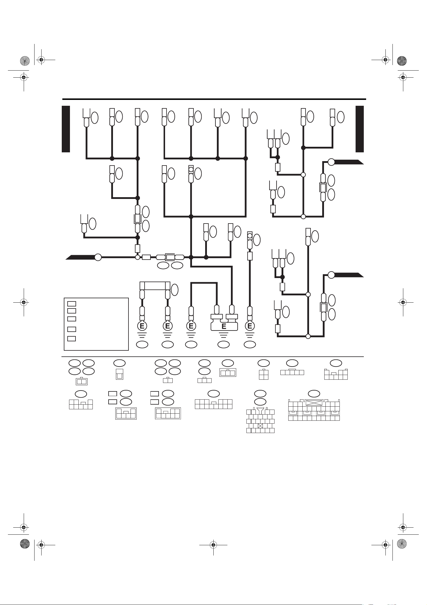
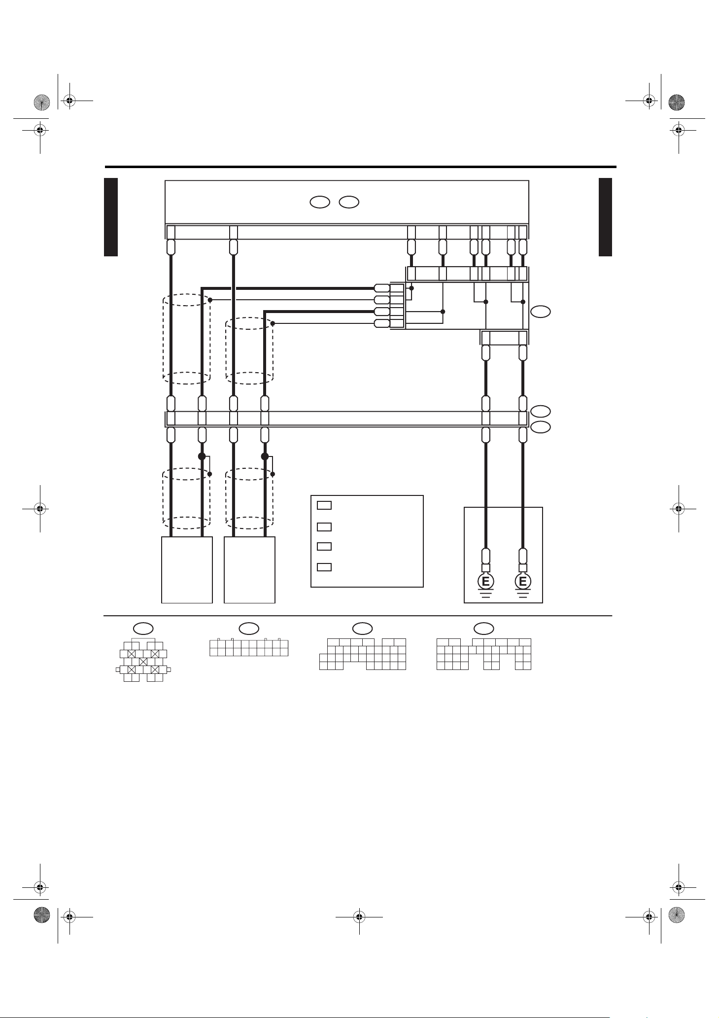
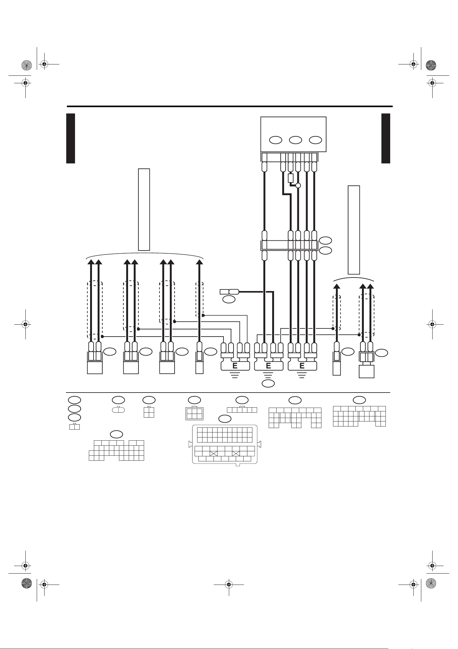
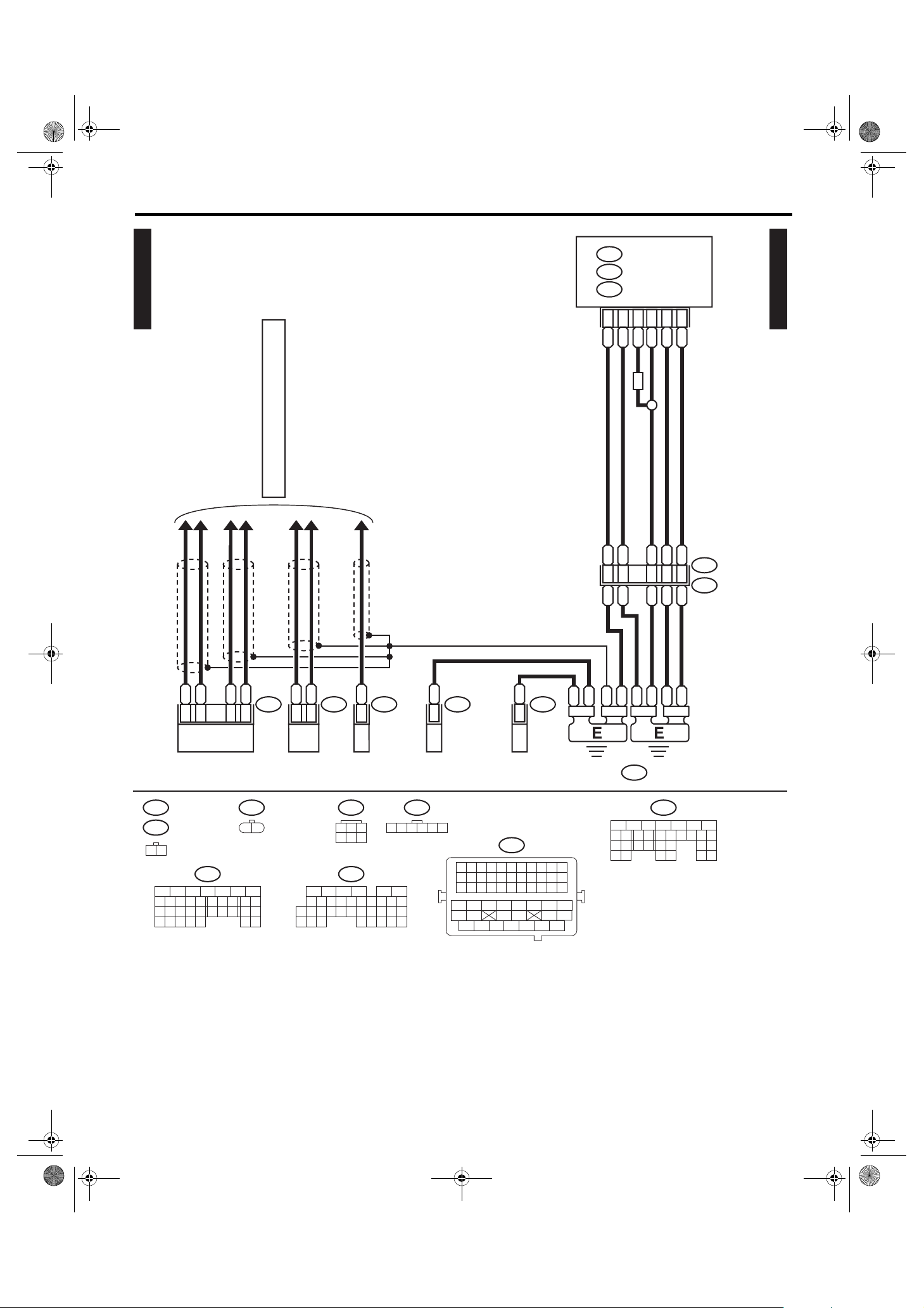
4. Ground Circuit
A: WIRING DIAGRAM
F106
B 3
GND-01
PWM CONTROLLER (H6 MODEL)
1
F17
B
MAIN FAN MOTOR (H4 MODEL)
F11
B1
TB
SEC ONDA RY AIR P UMP
FRONT CLEARANCE &
B2
MAIN FAN MOTOR
TB
NA
F3
B2
FRONT TURN SIGNAL LIGHT RH
F17
RELAY HOLDER
B2
FRONT FOG LIGHT RH
F21
B2
FRONT FOG LIGHT LH
F27
B9
(FWD SWITCH)
4A
F6
B2
KEYLESS BUZZER
FRONT CLEARANCE &
FRONT TURN SIGNAL LIGHT LH
B19
(H4 MODEL)
MAIN FAN RELAY 2
F102
MAI N F USE BOX (M/ B)
F19
B2
F27
B C12
F35
C:
R55
B4
SUNROOF CONTROL MODULE
(SEDAN MODEL)
B225
GR 20
POWE R WIN DOW RELAY
SHADE MIRROR
2
B2
VAN ITY
MIRROR ILLUMI. LIGHT RH
B32
MIRROR HEATER RELAY
R51
B225
SEAT BELT &
B4
AIR BAG WA RNING L IGH T
B26
DAYTIME RUNN ING LIGH T RELAY
R150
B225
R57
B
B225
B40
SEAT HEATER RELAY
R54
B2
VAN ITY MI RROR
ILLUMI. LIGHT LH/HOME LINK
B32
B7
TURN SIGNAL & HAZARD MODULE
B1
ROOM LIGHT
BB 1
R52
R50B90
A
B
B1
SPOT MAP LIGHT
GND-03
GND-02
R56
GND-01
B
B181
TB
1 2
R52
1 2 3
B32
1 2 3
4 5 6 7 8
:
F11
F17
F102
*
GB-1GP
1
B
(GRAY)
(GRAY)
(BLACK)
1 2
:
R54
1 2 3
R55
1234
6 7 8 9510
:
2
*
(GRAY)
R51
R54
R56
(BLACK)
(BLACK)
R57
3 2 1
C:
1 2
6 7 8 9
F35
:
OT
:
OT
(BLUE)
3
4 5
10 11 12
GB-2
F6
F21
12
2 3 4 5 6
1
B
(BLACK)
(BLACK)
R150
1 2 3
8 9
(GRAY)
B
GR
1
2
GR
GR
:
OB
F6
:
OB
F21
1 2
R50
4 5 6 7
10 11 12 13 14 15 16
B182 B181
(BR OWN)
(BR OWN)
12
3 4
5
7
:
NA
9
10
11 12
6
8
25
26
27
RELAY BLOCK
: NON-TURBO MODEL
NA
: TURBO MODEL
TB
: 4AT MODEL
4A
: WITH HOME LINK
1
*
: WITHOUT HOME LINK
2
*
: OUTBACK MODEL
OB
: EXCEPT FOR OUTBACK MODEL
OT
(BLACK)
F17
(GRAY)
F106
2 1
1 2 3
(BLACK)
B225
13
14
15 16
29
30
3128
32
21
17
22
18
20
23
19
24
37
33
38
34
3936
35
40
RELAY HOLDER
F3
F19
1 2 3
1110
8
12
13
(GRAY)
(GRAY)
9
14
F27
4 53
6
7
15
(BLACK)
17
1
2
18
1916
20 21 22
WI-13124
WI-22

asieps_tobira.book 23 ページ 2012年1月17日 火曜日 午後6時33分
Ground Circuit
WIRING SYSTEM
GND-02
DAYTIME RUNN ING LIGH T
B242
B10
CONTROL MODULE
B350
B1
KEY LOCK SOLENOID
B71
B16
B2
COMBINATION SWITCH
(LIGHTING)
B20
B
BOX (M/ B)
MAIN FUSE
B116
B4
AT SELE CT LEV ER
B70
B2
COMBINATION SWITCH
(WIPER)
B143
B:
BA5
B A14
TCM (5AT MODEL)
BY A19
BY B21
FUS E & RELAY BOX (F/B)
B54
A:
BD8
B55
B:
B152
D:
TEST MODE CONNECTOR
B76
BY 2
BY 3
STEERING ANGLE SENSOR
(WITH VDC)
BY C8
BODY INTEGRATED UNIT
B
BY 24
B36
i1
16
BY
B98
R2
B231
BY C9
B23
BY
BY
BY B22
B280
B:
B281
C:
REMOTE ENGINE START
C
D
E
BY 24
CONTROL UNIT
GND-06
GND-06
GND-04
GND-02
B180
GND-01
B76
1
2
2 3 64 571 8 9
11 12 1513 14 1610 17 18
13 14 15 16 17 18 19 20 21 22 23 24
B
(GREEN)
3412 89
B70
B180
567
1
B231
B350
2 3 4
10 11 12
B
GB-6
D:
2
1
5 6 7 8 9
(GRAY)
B152
3 4
1234 56789
10 11 12 13 14 15 16 17 18 19 20
21
9
10
8
20 21
1234
10
6 7 8 9510
B:
B143
C:
B281
11 12 13 14 15
2422 23 25
B242
43
567
16 17 18 19
26 27 28
B
BY
GB-4
B116
1 2 3 4 5
6 7 8 9
56782194310
11 12 13 14 15 16
17 18 19 20 21
242223 25
10 11 12
i1
2726 28
B98
1 2 3
8 9
12 7 8 95634
10 11 12
19 20 21
4 5 6 7
10 11 12 13 14 15 16
A: B54
13 14 15 16 17 18
8219
21 30
3
10
22 23
22 23 24
B:
B280
11 12 13 14 15
24 25 26 27
9
1234
10 11 12
19 20 21
5467
16 17 18
19 20
28 29
GND-03
F
B71
23456718
10 11 12 13 14 15 16 17
B: B55
135614 15
(GRAY)
789
16 17 18
22 23 24
WI-13125
WI-23

asieps_tobira.book 24 ページ 2012年1月17日 火曜日 午後6時33分
Ground Circuit
WIRING SYSTEM
GND-03
GND-01
ROLL CONNECTOR
GND-02
8
BY
B230
BY 4
YAW R ATE S EN SO R
B25
B22
VDC CONTROL MODULE
GV
B A16
BY A14
AUTO A/C
CONTROL MODULE
B310
B A16
B282
A:
FRONT WIPER MOTOR
B8
B2
B301
B15
B12
ABS CONTROL MODULE
GA
B12
B4
INHIBITOR SWITCH
(2.5L NON-TURBO MODEL)
B10
B3
PRESSURE SWITCH
B77
B7
(MA NUAL A/C)
MOD E AC TUATOR
A
B68
B116
BY 10
BY 6
BY 8
BY 2
AT SELE CT LEV ER
B88
B3
EVAPORATOR THERMO SWITCH
(MA NUAL A/C)
3
B362
B
FUEL PUMP RELAY
(H6 MODEL•TURBO MODEL)
F
B16
B2
SWITCH
WIPER DEICER
BRAKE FLUID LEVEL
B86
B1
(AUTO A/ C)
POWE R TRA NSISTOR
B98 R2
i26
AUDI O
B11
B177
B2
: TERMI NAL No. OPTIONAL
1
*
ARRANGEMENT
AMONG 1, 2, 3, 4, 5 AND 6
7
BB
B
AUDI O B RACKET G ROUND
B2
HOOD SWITCH
G
i29
11
B
B321
GND-04
R99i54
AUX BOX
B11
21
B
GND-03
C8
C1R43
(GRAY)
B16
1
2
1 2
5
7 8
6
RELAY HOLDER
B321
21
(BLACK)
B362
3
4
R43
45 6
123
11 12 19 20 2113 14 15 16 17 18 22
B177
21
1 2 3 4
5 6 7 8
9
789
B12
10 11
B10
3
10
1
4
2
(GRAY)
12
(GRAY)
B
BY
GB-7
B86
12
3 4
B116
i54
1 2 3 4 5
6 7 8 9
10 11 12
13 1412 15
(BLACK)
B230
1
2
3
4
(BLACK)
B301
456789
231
16 17 18 19 20
(GRAY)
B8
132
4 5
1 2 3 4 5 6
7 8 9
10 11
21 22 23 24 25 26
B
2 3 4 5
1
i26
10 11 12 13 14
23 2422 25
B88
C8
2 3 4 5 6
1
1 2 3
8 9
10 11 12 13 14 15 16
456789
231
26 27 28 29 30
B98
4 5 6 7
B310
31 32 33 34 35 36
B
GRGB-5
(GREEN)
B77
1
2 3 4 5 6 7
A:
12345678
10 11 12 13 14 15 16
9
(BLACK)
10 11 14 15 16 17 18 19
12 13
37 38 39 40
41 42 43 44 45 46
B68
B282
WI-13126
20 21
21
3
87654
WI-24

asieps_tobira.book 25 ページ 2012年1月17日 火曜日 午後6時33分
Ground Circuit
WIRING SYSTEM
GND-04
GND-03
1
C3
B
(CO NSO LE BOX)
REA R AC CESSORY POWE R SUPPLY SOCKET
REAR COMBINATION
LIGHT RH
G
2
B
SEAT HEATER SWITCH
R26
B3
SD
C2
B
B7
REAR COMBINATION
B
B17
R28
B3
LIGHT LH
SD
TRAILER CONNECTOR
R43
C1
B3
REAR COMBINATION
LIGHT RH
WG
R79
B6
WG
R26
B3
REAR COMBINATION
LIGHT LH
WG
FUEL PUMP ASSY
BY
R213
R15
BY 3
R28
B3
FRONT DOOR SWITCH LH
R58
BY 4
GR 6
GR
R67
R46
B5
OF
R9
R12
B3
FRONT DOOR SWITCH RH
REA R AC CESSORY
BY 6
NAVIGATION CONTROL MODULE
B1
POWE R S UPPLY SOCKET
(CARGO ROOM)
WG
R226
TPM CONTROL MODULE
R32
9
BY
B1
POWER SEAT (DRIVER SEAT)
R211
FRONT SEAT BELT SWITCH LH
R109
R8
BY 1
R188
B1
POWE R S EAT
(PASSENGER SEAT)
BY 3
REAR DOOR SWITCH RH
B
8
B
R122
B5
CONDENSER
(FUEL PUMP)
WF
FUEL PUMP CONTROL UNIT
R16
R22
BY 3
REAR DOOR SWITCH LH
H
I
BY9
i102R167
BY
R142
B2
OF
R169
BY 7
IMPACT SENSOR
GND-06
GND-06
GND-04
GND-02
C3
R32
1
2
R79
13
2
456
R188
1 2
1 2 3
4 5 6 7 8
E
(BLACK)
R213
B
BY
GB-8
(BLACK)
R142
121
R169
123 4
5 6 7 8
45 6
123
11 12 19 20 2113 14 15 16 17 18 22
1
: TERMI NAL No. OPTIONAL
*
ARRANGEMENT
AMONG 1, 2, 3, 4, 5 AND 6
2
: TERMI NAL No. OPTIONAL
*
ARRANGEMENT
AMONG 7, 8, 9, 10, 11 AND 12
R9
R12
R43
1
2
3
R16
R22
1
2
3
R122
2
1
5 6 7 8 9
789
10
R226
3 4
10
1
2 3 4
R8
1 2 3
6 7 8 9
C2
: SEDAN MODEL
SD
: WAGON MOD EL
WG
: WITHOUT FUEL PUMP
OF
CONTROL UNIT
: WITH FUEL PUM P
WF
CONTROL UNIT
WG :
R26
WG :
R28
12
4
3
4 5
10 11 12
1 2 3 4 5 6
7 8 9
R109
1 2
3 4
i97
i99
i100
(BLACK)
(BLACK)
(BLACK)
10 11 12
B
GB-9
::SD
R26
SD
R28
13
2
456
R211
1 2 3 4 5 6
7 8 9
10 11 12
BY
R58
12
34
56
J
(GRAY)
2 3
1
98
GND-05
R67
12
3456
i102
4 567
1110 12 13 14 15 16
WI-13127
WI-25
asieps_tobira.book 26 ページ 2012年1月17日 火曜日 午後6時33分
Ground Circuit
WIRING SYSTEM
R66
B2
GND-05
HIGH-MOUNTED STOP LIGHT
(REAR SPOILER)
TRU NK LID ACTUATOR
2
R19
B
HIGH-MOUNTED STOP LIGHT
GND-04
: SEDAN MODEL
SD
: WAGON MOD EL
WG
: WITHOUT SIDE TURN
OS
WITH MIRROR HEATER
: WITH SIDE TURN
WS
WITH MIRROR HEATER
: TERMI NAL No. OPTIONAL
1
*
ARRANGEMENT
AMONG 1, 2, 3, 4, 5 AND 6
J
R77
B2
LICENSE PLATE LIGHT RH
R186
B1
& SWITCH
R76
B2
LICENSE PLATE LIGHT LH
BB7
R60R24
SD
WG
AIR BAG C ONT ROL MOD ULE
27
B
B
GAB-1 GAB-2
D37
B1
LUG GAGE ROO M L IGHT
1
D46
B
REAR GATE LATCH SWITCH
B B3
R38 D34
28
AB6
BW
BW
D43
B3
REAR WIPER MOTOR
D48
B
REAR DEFOGGER
BACK-UP LIGHT LH
REAR GATE GROUND
B
B2
HIGH-MOUNTED
STOP LIGHT
D91
B1
B
D39
B1
BACK-UP LIGHT RH
B
B2
LICENSE PLATE LIGHT
D87
REAR DEFOGGER GROUND
GDGB-10 GB-11
B
SD
B
D44
R65
5
4
B
B
OUTER MIRROR ASSY LH
(WITH SIDE TURN)
WS
B3
OS
OUTER MIRROR ASSY LH
(WITHOUT SIDE TURN)
5
B
OUTER MIRROR ASSY RH
(WITH SIDE TURN)
B3
OS
OUTER MIRROR ASSY RH
(WITHOUT SIDE TURN)
D5
4
B
WS
D5
D15
POWE R WIN DOW
D15
D7
B 7
MAIN SWITCH
D125
B3
PAS SE NG ER'S D OOR L OC K S WI TC H
D82
B2
DOOR KEY SWITCH
GND-06
K
BB2
i76D83
GND-06
L
BB2
i101D84
GND-05
D39
R19
R66
D44
2 1
R60
1 2 3
4 5 6 7 8
OS
OS
D46
1
2
:
:
2
635
(BLACK)
D5
D15
4
R76
D87
D91
R77
1 2
:
D5
WS
:
D15
WS
1
3
2
1
4
5678
D37
R186
1 2 3
172 3
8 9
D7
10 11
D82
4 5 6
12 13 14
(BR OWN)
123
D43
12
3
D83
D84
5678219
10
11 12 13 14 15
17 18 19
16
20 21
4
3
2422 23 25
4
(BLACK)
D125
2 3 4 5
1
AB6
1 2 3 4 5 6
7 8 9
10 11 12 13 14 16 1715
18 19 20 21 22 23 24 25 26 27 28
D34
(YE LLOW )
321
87654
WI-13128
WI-26

asieps_tobira.book 27 ページ 2012年1月17日 火曜日 午後6時33分
Ground Circuit
WIRING SYSTEM
TV MONITOR
GND-06
GND-02
GND-04
1
: TERMI NAL No. OPTIONAL
*
ARRANGEMENT
AMONG 1, 2, 3, 4, 5 AND 6
2
: TERMI NAL No. OPTIONAL
*
ARRANGEMENT
AMONG 7, 8, 9, 10, 11 AND 12
GND-05
GND-05
GND-02
GND-04
A/C CONTROL PANEL
(MA NUAL A/C)
i17
BY 13
i119
BY 16
BY 15
JOINT GROUND
CONNECTOR
2
BY
*
2
BY
*
2
BY
*
1
BY
*
1
BY
*
1
BY
*
1
BY
*
2
D
I
BY
*
i97 i98
2
*
1
*
1
*
1
*
1
*
1
*
1
*
BY
BY
BY
BY
BY
BY
BY
A/C CONTROL PANEL
(AUTO A/ C)
i88
BY 5
K
L
C
i22
BY 3
HAZARD SWITCH
BY 9
PUSH SWITCH
JOINT GROUND
CONNECTOR
1
B
*
1
B
*
1
B
*
1
B
*
1
B
*
1
B
*
i100 i99
CLOCK
BY 6
i24
GLOV E B OX ILLUM I. L IGHT
i59
B1
BY 7
KEY LES S ENTRY
CONTROL MODULE
FRO NT ACCES SORY
POWE R S UPPLY SOCKET
B
B
B
B
B
i96
B2
i78
BY 5
BY 2
1
*
1
*
1
*
1
*
1
*
i84
BY A21
A:
BODY INTEGRATED UNIT
i23
MIRROR SWITCH
REMOTE CONTROL
BY A12
BY A11
COMBINATION METER
i6
B14
A/C CONTROL PANEL
i10A:
B1
(MA NUAL A/C)
GND-06
i15
H
i23
1 2
i97 i99 i78 i6
i98 i100
1 2 3 4 5 6
7 8 9
i24
1 2
10 11 12
i22 i88i96i15
1 2 3 4
1 2 3 4 5 6 7
8 9
10 11 12
123
4
(BLUE)
13 14 15
123
65
5 6
182 3 4 5 6 7
9
10 11 12 13 14 15 16
7 8
B
BY
GB-3
(BLACK)
i17
4
1 2 3 4
567
8
3 45 6789
12
11 13 22
12
234
i10A:
51678
(GREEN)
19 20 2114 15 16 17 18
10
i119
51678
234
i84
1 2 3 4 5 6 7 8
9
10 11 12 14 15 16 17 18 19 20 21 22 23
24 25 26 27 28 29 30 31 32 33 34 35
13
1234
6 7 8 9510
(GRAY)
i59
WI-13311
WI-27
asieps_tobira.book 28 ページ 2012年1月17日 火曜日 午後6時33分
Ground Circuit
WIRING SYSTEM
TCM (4AT MODEL)
B55B54A: B:
GND-07
A27
L
L
Y14
FRONT
WHEEL
SPEED
SENSOR
G
18
W
A1
W
W
5Y
TORQU E
CONVERTER
TURBINE
SPEED
SENSOR
A16
R
1
1
G
*
1
SB
*
2
B
*
2
SB
*
B
W 10
1
: TERMINAL No. OPTIONAL
*
ARRANGEMENT
AMONG 1, 11 AND 12
: TERMINAL No. OPTIONAL
2
*
ARRANGEMENT
AMONG 2, 3 AND 13
: TERMINAL No. OPTIONAL
3
*
ARRANGEMENT
AMONG 4, 5, 14 AND 15
: TERMI NAL No. OPTIONAL
4
*
ARRANGEMENT
AMONG 6, 7, 16 AND 17
A2
G
2
*
*
B22
P
3
B23
PG
3
*
*
3
*
P
P
19B
B
B20
OrW
4
*
B21
Or
4
4
Or
Or
20B
B
*
JOINT
CONNECTOR
B53
*
B11
T4
GND-07
(GRAY)
B11
1 2
3 4
5 6 7 8
9
10 11 12
13 14 15 16
17 18 19 20
B53
123456789
11 12 13 14 15 16 17 18 19 20
AT CONTROL
A: B54
10
1 2 3 4 5 6
987
17 18 19 202821 22 23
30
29 3231
2524
33 34 35
1610 11 12 13 14 15
2726
10
98
202821 22 23
29
30
B: B55
11 12 13 14 15
3231
5672134
16
17 18 19
2524
26 27
33 34 35
WI-13129
WI-28

asieps_tobira.book 29 ページ 2012年1月17日 火曜日 午後6時33分
Ground Circuit
TCM (5AT MODEL)
B55B54A: B:
WIRING SYSTEM
GND-08
BW A16
BWWB
B11
7
T4
WB
3
AT1
TORQU E
CONVERTER
TURBINE
SPEED
SENSOR 1
WL
2
1
B
WB
REAR
WHEEL
SPEED
SENSOR
B16
WR
WR
7
WL
B18
YL
YL
5
W
W
B
GND-08
B12
T3
AT1
1 2 3
B12
123
5 6
(BR OWN)
4
7 8
(GRAY)
B11
1 2
3 4
5 6 7 8
9
10 11 12
13 14 15 16
17 18 19 20
A: B54
12 7 8 95634
10 11 12
13 14 15 16 17 18
19 20 21
22 23 24
B
1234
10 11 12
19 20 21
135614 15
(GRAY)B: B55
789
16 17 18
22 23 24
WI-13130
WI-29
asieps_tobira.book 30 ページ 2012年1月17日 火曜日 午後6時33分
Ground Circuit
WIRING SYSTEM
ECM (2.5L NON-TURBO MODEL)
A:
B134
D:
B136C:B137
GND-09
REF. TO ENGINE ELECTRICAL SYSTEM
[E/G(H4)-06]
PCV DI AGNOSIS
CONNECTOR
B
1
E61
D7
GND-09
R
RBL
52
BL C15
BL A5
LR D3
MT
BW 37 LR
BR D1
BW D2
BR
BW
B21
E2
BY 35
BY 34
BW 36 BL
REF. TO ENGINE ELECTRICAL SYSTEM
[EG(H4)-05]
CRANKSHAFT
(LIGHT GRAY)
E10
(GRAY)
E15
(DARK GRAY)
E61
1 2
B
W
E10
1
2
POSITION
SENSOR
C: B136
1 2 3 4
987
17 18 19 202821 22 23
30
29 3231
CAMSHAFT
POSITION
SENSOR
(GRAY)
E14
12
L
G
1
2
5 6
2524
33 34 35
E15
E23
12
3 4
1610 11 12 13 14 15
2726
R
W
4
6
ELECTRONIC
THROTTLE
CONTROL
(DARK GRAY)
E57
R
1
KNOCK
SENSOR
(GRAY)
E22
31
2
654
123456789
12 13 14 15 16 17 18 19 20 21 22
23 24 25 26 27 28 29 30 31 32 33
34 35
42 43
48 49 50 51 52 53 54
E14
B21
36 37 38 39
44 45 46 47
BW
BW
E57
2 3 4 5 6
1
(BLACK)
BR
10 11
40 41
BR
BR
(BLACK)
B
BL
BWBWBW
GE
D: B137
8
10 11 12 13 14 15
9
19 20 22
18 2521 23 24
56
28 29
BY
L
BY
72134
16
17
30
3126 27
3 Y
REAR
OXYG EN
SENSOR
8
9
19 20 22
18
28 29
E23
10 11 12 13 14 15
30
P
1
3
FRO NT OXYGE N
(A/F) SENSOR
A: B134
5
2521 23 24
3231
6
E22
16
26 27
33 34
72134
17
WI-13131
WI-30

asieps_tobira.book 31 ページ 2012年1月17日 火曜日 午後6時33分
Ground Circuit
WIRING SYSTEM
A:
B134
D:
ECM (3.0L MODEL)
B137
GND-10
REF. TO ENGINE ELECTRICAL SYSTEM
[E/G(H6)-08•09]
BY A5
BY
BL 36
RD7
R52R
GND-10
LR D3
BR D1
BW A3
BW D2
B21
E2
LR 37 LR
BP 34 BR
BW 35 BW
(LIGHT GRAY)
E10
(BLUE)
E14
(BLUE)
E48
1 2
B
W
1
2
CRANKSHAFT
POSITION
SENSOR
2 3 4 5 6
1
E10
E57
ELECTRONIC
THROTTLE
CONTROL
(BLACK)
W
Or
E57
4
6
KNOCK
SENSOR 1
D:
B137
8
10 11 12 13 14 15
9
19 20 22
18 2521 23 24
56
28 29
R
BL
E14
2 W
72134
16
17
30
3126 27
2 B
KNOCK
SENSOR 2
8
9
19 20 22
18
28 29
E48
A:
B134
10 11 12 13 14 15
30
5
3231
BR
6
72134
16
17
2521 23 24
26 27
33 34
123456789
12 13 14 15 16 17 18 19 20 21 22
23 24 25 26 27 28 29 30 31 32 33
34 35
42 43
48 49 50 51 52 53 54
LR
GE
36 37 38 39
LR
BP
BW
(BLACK)
B21
10 11
44 45 46 47
40 41
WI-13132
WI-31
asieps_tobira.book 32 ページ 2012年1月17日 火曜日 午後6時33分
Ground Circuit
WIRING SYSTEM
GND-11
REF. TO ENGINE ELECTRICAL SYSTEM
[E/G(TB)-07•08•09]
B134A:
ECM (TURBO MODEL)
B136C:
B137D:
BL C15
BR D1
BW D2
MT
GND-11
LR D3
BL A5
YB D7
B
1
ELECTRONIC
THROTTLE CONTROL
(LIGHT GRAY)
E10
(BLACK)
E40
1 2
A: B134
8
10 11 12 13 14 15
9
19 20 22
18
28 29
3231
30
B 36 BL
B
28 29
B 37 LR
B
56
YB
B 54
B
B21
E2
16
30
72134
17
3126 27
BR
35 BW
34
B
B
L
G
W
4
2
6
E14
12
5
6
72134
16
17
2521 23 24
26 27
33 34
W
E57
1
CRANKSHAFT
POSITION
SENSOR
(LIGHT GRAY)
17 18 19 202821 22 23
WR
2
1 2 3 4
30
29
E10
KNOCK
SENSOR
E41
13
2
456
C: B136
987
W
1
3231
E14
1
5 6
2524
33 34 35
BW
E40
1
SEC ONDA RY
AIR COMBINATION
VALV E LH
(BLACK)
E57
2 3 4 5 6
123456789
12 13 14 15 16 17 18 19 20 21 22
23 24 25 26 27 28 29 30 31 32 33
1610 11 12 13 14 15
2726
34 35
42 43
AIR COMBINATION
48 49 50 51 52 53 54
B4
SEC ONDA RY
VALV E RH
(BLACK)
B21
36 37 38 39
44 45 46 47
E41
10 11
40 41
B
BW
8
9
19 20 22
18 2521 23 24
BBB
GE-1
D: B137
10 11 12 13 14 15
WI-13133
WI-32
 Loading...