

Page 1

Basic Diagnostic Procedure
WIRING SYSTEM
1. Basic Diagnostic Procedure
A: BASIC PROCEDURES
1. GENERAL DESCRIPTION
The most important purpose of diagnostics is to
quickly determine which part is malfunctioning, to
save time and labor.
2. IDENTIFICATION OF TROUBLE SYMPTOM
Determine what the problem is based on the symptom.
3. PROBABLE CAUSE OF TROUBLE
Look at the wiring diagram and check the system’s
circuit. Then check the switch, relay, fuse, ground,
etc.
4. LOCATION AND REPAIR OF TROUBLE
1) Using the diagnostics, narrow down the causes.
2) If necessary, use a voltmeter, ohmmeter, etc.
3) Before replacing certain component parts
(switch, relay, etc.), check the power supply,
ground, for open wiring harness, poor connectors,
etc. If no problem is encountered, check the component parts.
5. SYSTEM OPERATION CHECK
After repairing, ensure that the system operates
properly.
B: BASIC INSPECTION
1. VOLTAGE MEASUREMENT
1) Using a voltmeter, connect the negative lead to a
good ground point or negative battery terminal and
the positive lead to the connector or component terminal.
2) Contact the positive lead of the voltmeter on
connector (A). The voltmeter will indicate a voltage.
3) Shift the positive lead to connector (B). The voltmeter will indicate no voltage.
To power
supply
Fuse
Switch
Light
5) The circuit is in good order. If a problem such as
a light failing to illuminate occurs, use the procedures outlined above to track down the malfunction.
2. CIRCUIT CONTINUITY CHECKS
1) Disconnect the battery terminal or connector so
there is no voltage between the check points.
Contact the two leads of an ohmmeter to each of
the check points.
If the circuit has diodes, reverse the two leads and
check again.
2) Use an ohmmeter to check for diode continuity.
When contacting the negative lead to the diode
positive side and the positive lead to the negative
side, there should be continuity.
When contacting the two leads in reverse, there
should be no continuity.
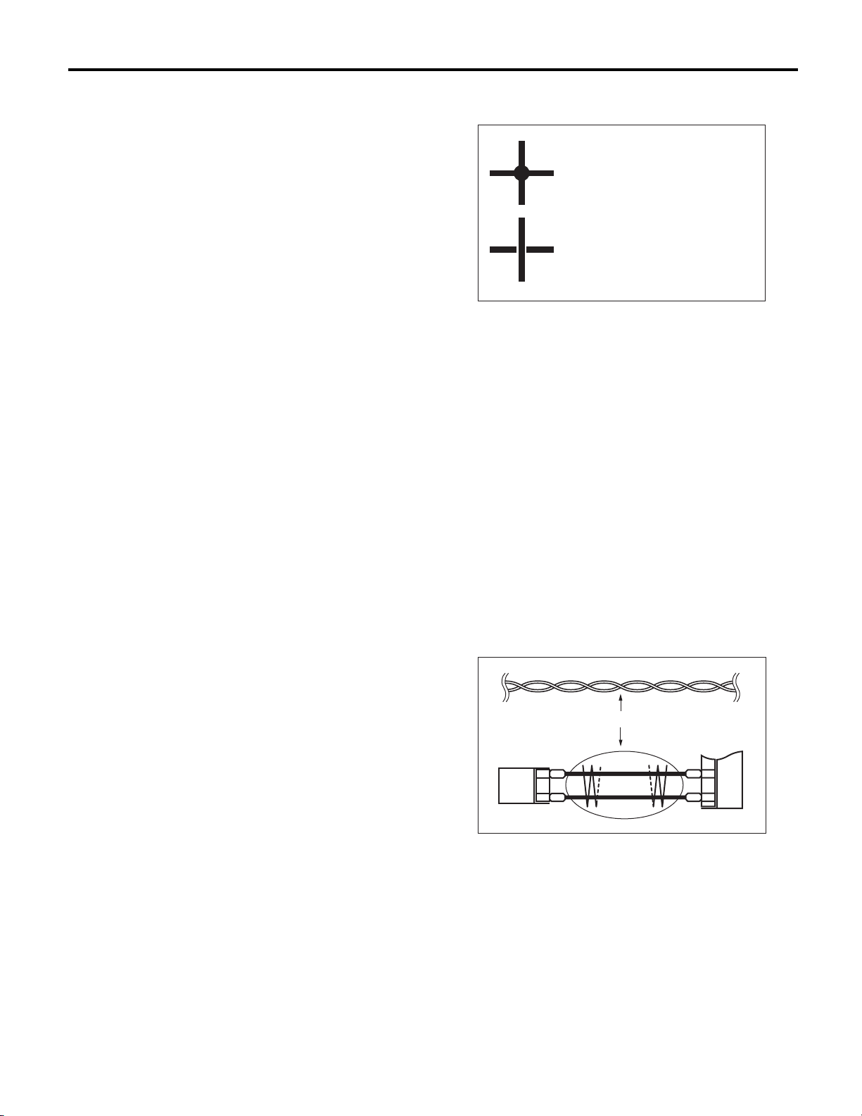
Continuity No continuity
WI-02740
3) The symbol “ — ” indicates that continuity
exists between two points or terminals. For example, when a switch position is at “3”, continuity exists among terminals 1, 3 and 6, as shown in the
table below.
Terminal
Switch Position
OFF
1
2
3
4
1
234
56
WI-02741
(A)
(B)
V
WI-02739
4) With the test set-up held as it is, turn the switch
to ON. The voltmeter will indicate a voltage and, at
the same time, the light will illuminate.
WI-3
Page 2

WIRING SYSTEM
Basic Diagnostic Procedure
3. HOW TO DETERMINE AN OPEN CIRCUIT
1) WITH VOLTMETER:
An open circuit is determined by measuring the
voltage between respective connectors and ground
using a voltmeter, starting with the connector closest to the power supply. The power supply must be
turned ON so that current flows in the circuit. If voltage is not present between a particular connector
and ground, the circuit between that connector and
the previous connector is open.
Open circuit or wiring
V
12V
2) WITH OHMMETER:
Disconnect all connectors affected, and check continuity in the wiring between adjacent connectors.
When the ohmmeter indicates “infinite”, the wiring
is open.
V
0V
WI-02742
Open circuit
4. HOW TO DETERMINE A SHORT CIRCUIT
1) WITH TEST LIGHT:
Connect a test light (rated at approx. 3 watts) in
place of the blown fuse and allow current to flow
through the circuit. Disconnect one connector at a
time from the circuit. Starting with the one located
farthest from the power supply. If the test light goes
out when a connector is disconnected, the wiring
between that connector and the next connector
(farther from the power supply) is shorted.
Test light
Shorted wiring
Fuse holder
WI-02744
2) WITH OHMMETER:
Disconnect all affected connectors, and check continuity between each connector and ground. When
the ohmmeter indicates continuity between a particular connector and a ground, that connector is
shorted.
Shorted connector
WI-09860
WI-02745
WI-4
Page 3

Basic Diagnostic Procedure
WIRING SYSTEM
C: HOW TO READ WIRING DIAGRAMS
1. WIRING DIAGRAM
The wiring diagram of each system is illustrated so that you can understand the path through which the electric current flows from the battery.
Sketches and codes are used in the diagrams. They should read as follows:
• Each connector and its terminal position are indicated by a sketch of the connector in a disconnected state
which is viewed from the front.
2
1
3
4
4
Viewed from this direction
WI-02746
• The number of poles or pins, presence of a lock are indicated in the sketch of each connector. In the
sketch, the highest pole number refers to the number of poles which the connector has. For example, the
sketch of the connector shown in figure indicates the connector has 9 poles.
Connector used in vehicle
Sketch Symbol Number of poles
Double frames
43
98
Indicates the number of poles.
Indicates a lock is included.
12
56
Single frame
Indicates a lock
is included.
2
65
7
3
8
7
Connector shown in wiring diagram
1
4
9
Numbered in order from upper
right to lower left.
Numbered in order from upper
left to lower right.
WI-02747
WI-5
Page 4

WIRING SYSTEM
Basic Diagnostic Procedure
• When one set of connectors is viewed from the
front side, the pole numbers of one connector are
symmetrical to those of the other. When these two
connectors are connected as a unit, the poles
which have the same number are joined.
1
2
3
6
5
44
3
6
2
5
1
WI-00107
• WIRING DIAGRAM:
The connectors are numbered along with the number of poles, external colors, and mating connections in the accompanying list.
• The sketch of each connector in the wiring diagram usually shows the (A) side of the connector.
The relationship between the wire color, terminal
number and connector is described in the figure.
• The following color codes are used to indicate
the colors of the wires.
Color code Color
LBlue
BBlack
YYellow
GGreen
RRed
WWhite
Br Brown
Lg Light green
Gr Gray
PPink
Or Orange
Sb Light blue
V Violet
SA Sealed (Inner)
SB Sealed (Outer)
YG
NOTE:
A wire which runs in one direction from a connector
terminal sometimes may have a different color from
that which runs in the other direction from that terminal.
i2
BR
1
RW
3
Wire color :
BR (No. 1 terminal)
RW (No. 3 terminal)
(A)
i2F4
12
34
WI-02748
• In the wiring diagram, connectors which have no
terminal number refer to one-pole types. Sketches
of these connectors are omitted intentionally.
BB
SA
SB10
YL9
YG8
SB22
SA20
SB
YL
SB
YL 2
YG 1
SA 1
WI-00110
B15F10
WI-00109
WI-6
Page 5

Basic Diagnostic Procedure
WIRING SYSTEM
• The wire color code, which consists of two letters
(or three letters including Br or Lg), indicates the
standard color (base color of the wire covering) by
its first letter and the stripe marking by its second
letter.
YB
BlackMarking color :
Reference color : Yellow
WI-03797
• The table lists the nominal sectional areas and
allowable currents of the wires.
CAUTION:
When replacing or repairing a wire, be sure to
use the same size and type of the wire which
was originally used.
NOTE:
• The allowable current in the table indicates the
tolerable amperage of each wire at an ambient
temperature of 40°C (104°F).
• The allowable current changes with ambient
temperature. Also, it changes if a bundle of more
than two wires is used.
Nominal sectional area
0.3 7/0.26 1.8 7
0.5 7/0.32 2.2 (or 2.0) 12
0.75 30/0.18 2.6 (or 2.4) 16
0.85 11/0.32 2.4 (or 2.2) 16
1.25 16/0.32 2.7 (or 2.5) 21
2 26/0.32 3.1 (or 2.9) 28
3 41/0.32 3.8 (or 3.6) 38
5 65/0.32 4.6 (or 4.4) 51
8 50/0.45 5.5 67
mm
2
No. of
strands/
strand diameter
Outside
diameter of
wiring
mm
Allowable
current
Amps/
40°C (104°F)
• Each unit is either directly grounded to the body
or indirectly grounds through a harness ground terminal. Different symbols are used in the wiring diagram to identify the two grounding systems.
B
Direct ground Indirect terminal
ground
WI-02750
• The ground points shown in the wiring diagram
refer to the following:
NOTE:
All wiring harnesses are provided with a ground
point which should be securely connected.
: BODY GROUND
GB
: ENGINE GROUND
GE
: RADIO GROUND
GR
: VDC GROUND
GV
WI-25479
WI-7
Page 6

Basic Diagnostic Procedure
WIRING SYSTEM
• Relays are classified as normally-open or normally-closed.
The normally-closed relay has one or more contacts. The wiring diagram shows the relay mode when the energizing circuit is OFF.
Relay type
Normally-open type
Normally-closed type
4-pole
6-pole
4-pole
Energizing circuit OFF
Energizing circuit ON
Mixed type
Key to symbols:
: Current flows.
: Current does not flow.
6-pole
WI-16724
WI-8
Page 7

Basic Diagnostic Procedure
• Each connector number shown in the wiring diagram corresponds to that in the wiring harness. The
location of each connector in the actual vehicle is
determined by reading the first character of the
connector (for example, a “F” for F8, “i” for i16, etc.)
and the type of wiring harness. The first character
of each connector number corresponds to the area
or system of the vehicle.
Symbol Wiring harness and cord
F Front wiring harness
B Bulkhead wiring harness
E Engine wiring harness
T Transmission cord
D
i Instrument panel wiring harness
R
AB Airbag wiring harness
Door cord LH & RH, Rear gate cord
Rear door cord LH & RH
Rear wiring harness,
Fuel tank cord,
Roof cord, Rear gate cord,
WIRING SYSTEM
F58
F23
F98
FRONT TURN SIGNAL
LIGHT LH (UPPER)
FRONT TURN SIGNAL
LIGHT LH (LOWER)
F19
F22
F100
F21
F47
F5
F27
F34
F96
Each connector number
shown in wiring diagram
corresponds to that in
BG2
B1
F19
BG3
B2
F22
the vehicle.
(GRAY)
F3
(GRAY)
F19
1 2
WI-02753
WI-9
Page 8

Basic Diagnostic Procedure
WIRING SYSTEM
D: SYMBOLS IN WIRING DIAGRAMS
A number of symbols are used in each wiring diagram to easily identify parts or circuits.
Example
SYMBOLS OF WIRE
CONNECTION AND
CROSSING
SPECIFICATION
CLASSIFICATION
OR
WR
RELAY
: WITHOUT REAR DEFOGGER
: WITH REAR DEFOGGER
DIODE
HEAD LIGHT
RELAY
No. 3 10A
3
F39
LR
H/L(2L)-01
HEADLIGHT LH
HEADLIGHT RH
DIMMER
& PASSING
SWITCH
PASSLOW
UP
LIGHTING SWITCH
OFF
GROUND
MAIN FUSE BOX (M/B)
SBF-1 100A
HEAD LIGHT
RELAY
RH
LOW
LOW
DIODE
LH
No. 9 15A
7
WL
MB-11
RL
2
HIGH
R
1
YL
3
F23
2
WL
HIGH
R
1
3
YL
F7 B61
OR WR
8
3
2
7
YB
17
17
B
16
16
13 13
B71
YB
1
2
YR
B112
No. 8 15A
2
5
G
RL
MB-10
YL
YR
YL
B
REF. TO GND-02
P-SUP-02
A
P-SUP-02
B
P-SUP-02
C
P-SUP-04
D
POWER SUPPLY CIRCUIT
TO POWER SUPPLY CIRCUIT
MB-11
MB-10
M/B FUSE NO.
8
M/B FUSE NO.
RL
REF. TO ST(MT)-01
REF. TO ST(AT)-01
REF. TO FOG(H4)-01
REF. TO FOG(H6)-01
P
PARKING BRAKE
SWITCH
WL
WL
R
YL
F44
R4
WIRE TRACING ON
EXTENDED WIRING
DIAGRAMS
FB-16
F/B FUSE NO.
9
(IG)
GR
4
WL
3
R
2
YL
17
R3
WG
7
P
R1
FUSE No. AND RATING
SBF-6 30A
SBF-4 50A
SBF-3 50A
SBF-2 50A
No. 2 15A
No. 1 20A
132
3
2
R
LR
MB-5
HEADLIGHT
11
RELAY
LB
F45
H1
B62
LB
WL
B1
R
A1
B36
SPECIFICATION
CLASSIFICATION
:
SEDAN
SDSD
PP
B99
WG
P
B97
SD
WAGON
:
WG
B112
12
L
123
4567
FUSE &
:A
:B
:C
:D
:E
:F
:G
123
F36 F38F68
R
BW
RELAY
BOX
(F/B)
B51
i5
B52
B152
B158
F40
F41
A2
:G:C:A
F41
(GRAY)
(BLACK)
F7
(
BLACK)
F23
LgB
D4
G4
WR
FB-37
W
A3
1234
5678
BG
D7
G7
BG
FB-36
12 3
45678
F44
M
L
K
J
I
H
G
F
E
P-SUP-04
P-SUP-04
P-SUP-04
P-SUP-04
P-SUP-03
P-SUP-03
P-SUP-04
P-SUP-03
P-SUP-04
G1
BL
FB-35
B51B52
No. 5 10A
Or
D11
D10
BR
FB-34
CONNECTOR 1
TWISTED PAIR LINE
CONNECTOR 2
CONNECTOR SKETCH
WI-25263
WI-10
Page 9
Basic Diagnostic Procedure
WIRING SYSTEM
1. RELAY
A symbol used to indicate a relay.
2. CONNECTOR 1
The sketch of the connector indicates the one-pole
types.
3. WIRING CONNECTION
Some wiring diagrams are indicated in foldouts for
convenience. Wiring destinations are indicated
where necessary by corresponding symbols.
(When two pages are needed for clear indication)
4. FUSE NO. & RATING
The “FUSE No. & RATING” corresponds with that
used in the fuse box (main fuse box, fuse and joint
box).
5. CONNECTOR 2
• Each connector is indicated by a symbol.
• Each terminal number is indicated in the corresponding wiring diagram in an abbreviated form.
• For example, terminal number “G4” refers to No.
4 terminal of connector (G: F41) shown in the connector sketch.
10.SYMBOLS OF WIRE CONNECTION AND
CROSSING
Symbol
Symbol Refers to wires which are
Refers to wires which are
connected and branched
at the dot point.
crossed but not connected.
WI-02755
11.POWER SUPPLY CIRCUIT
A symbol is used to indicate the power supply in
each wiring diagram.
“MB — 5”, “MB — 6”, etc., which are used as power- supply symbols throughout the text, correspond
with those shown in the “DC POWER SUPPLY
CIRCUIT” in the wiring diagram.
Accordingly, using the “DC POWER SUPPLY CIRCUIT” and wiring diagrams permits service personnel to understand the entire electrical arrangement
of a system.
6. CONNECTOR SKETCH
• Each connector sketch clearly identifies the
shape and color of a connector as well as terminal
locations. Non-colored connectors are indicated in
white or natural color.
• When more than two types of connector number
are indicated in a connector sketch, it means that
the same type connectors are used.
7. GROUND
Each grounding point can be located easily by referring to the corresponding wiring harness.
8.DIODE
A symbol is used to indicate a diode.
9. WIRE TRACING ON EXTENDED WIRING
DIAGRAMS
For a wiring diagram extending over at least two
pages, a symbol (consisting of the same characters
with arrows), facilitates wire tracing from one page
to the next.
A ←→ A, B ←→ B
12.CLASSIFICATION BY SPECIFICATION
When the wiring diagram differ according to vehicle
specifications, the specification difference is described by using abbreviations.
13.TWISTED PAIR LINE
Twisted pair lines are indicated in the following
manner in the wiring diagrams.
TWISTED PAIR LINE
P
V
B26
B25
WI-25264
10
P
9
V
WI-11
Page 10

Basic Diagnostic Procedure
WIRING SYSTEM
E: CONNECTOR SYMBOL IN WIRING HARNESS
A number of connector symbols are used in each wiring diagram to easily identify the wiring harness connectors.
Standard type: Female
Pole: From 1 to 8 Pole: From 9 to 20 Pole: More than 21
Standard type: Male
Water proof type: Female
Pole: From 1 to 8 Pole: From 9 to 20 Pole: More than 21
Water proof type: Male
WI-02756
WI-12
Page 11

Basic Diagnostic Procedure
F: ABBREVIATION IN WIRING DIAGRAMS
WIRING SYSTEM
Abbr. Full name
A/B Airbag
A/C Air Conditioner
A/F Air/Fuel (Air fuel ratio sensor)
ABS Anti-lock Brake System
ACC Accessory
ALT Generator
ASSY Assembly
AT Automatic Transmission
ATF Automatic Transmission Fluid
AWD All Wheel Drive
B, BAT Battery
CAN Communication Area Network
CM Control module
CVT Continuously Variable Transmission
D Drive Range
DN Down
E Ground
ECO Economy
ECM Engine Control Module
EEPROM
EGR Exhaust Gas Recirculation
EPB Electronic Parking Brake
F/B Fuse & Relay Box
FL Front Left
FR Front Right
G Gravity (G sensor)
H/L Headlight
HI High
I/F Interface
IG Ignition
ILLUMI Illumination
INT Intermittent
J/C Joint connector
LCD Liquid Crystal Display
L, LH Left Hand
LO Low
M Motor
M/B Main Fuse Box
MIST Wiper for mist (one touch)
MT Manual Transmission
N Neutral Range
NA Natural Aspiration
OP Optional Parts or Open
P Parking Range
PASS Passing
R Reverse Range
R, RH Right Hand
Electrically Erasable Programmable
Read-Only Memory
Abbr. Full name
RL Rear Left
RR Rear Right
SBF Slow Blow Fuse
ST Starter
SW Switch
TCM Transmission Control Module
TPMS Tire Pressure Monitor System
UP Up
VDC Vehicle Dynamics Control
VFD Vacuum Fluorescent Display
WASH Washer
WI-13
Page 12

WIRING SYSTEM
Working Precautions
2. Working Precautions
A: PRECAUTIONS WHEN WORKING
WITH THE PARTS MOUNTED ON
THE VEHICLE
1) When working under a vehicle which is jackedup, always be sure to use rigid rack.
2) The parking brake must always be applied during working. Also, in automatic transmission vehicles, keep the select lever set to the P (Parking)
range.
3) Be sure the workshop is properly ventilated
when running the engine. Further, be careful not to
touch the belt or fan while the engine is operating.
4) Be careful not to touch hot metal parts, especially the radiator and exhaust system immediately after the engine has been turned off.
B: PRECAUTIONS IN TROUBLE DI-
AGNOSIS AND REPAIR OF ELECTRIC PARTS
1) The battery cable must be disconnected from
the battery’s (–) terminal, and the ignition switch
must be set to the OFF position, unless otherwise
required by the diagnostics.
2) Securely fasten the wiring harness with clamps
and clips so that the harness does not interfere with
the body end parts or edges and bolts or screws.
3) When installing parts, be careful not to catch
them on the wiring harness.
4) When disconnecting a connector, do not pull the
wires, but pull while holding the connector body.
5) Some connectors are provided with a lock. One
type of such a connector is disconnected by pushing the lock, and the other, by moving the lock up.
In either type the lock shape must be identified before attempting to disconnect the connector.
To connect, insert the connector until it snaps and
confirm that it is connected securely.
EXAMPLE
WI-02758
6) When checking continuity between connector
terminals, or measuring voltage across the terminal
and ground, always contact tester probe(s) on terminals from the wiring connection side. If the probe
is too thick to gain access to the terminal, use “mini”
test leads.
To check water-proof connectors (which are not
measurable from the wiring side), contact test
probes on the terminal side. Be careful not to bend
or damage the terminals.
WI-02757
WI-09366
7) Sensors, relays, electrical unit, etc., are sensitive to strong impacts.
Handle them with care so that they are not dropped
or mishandled.
WI-14
Page 13
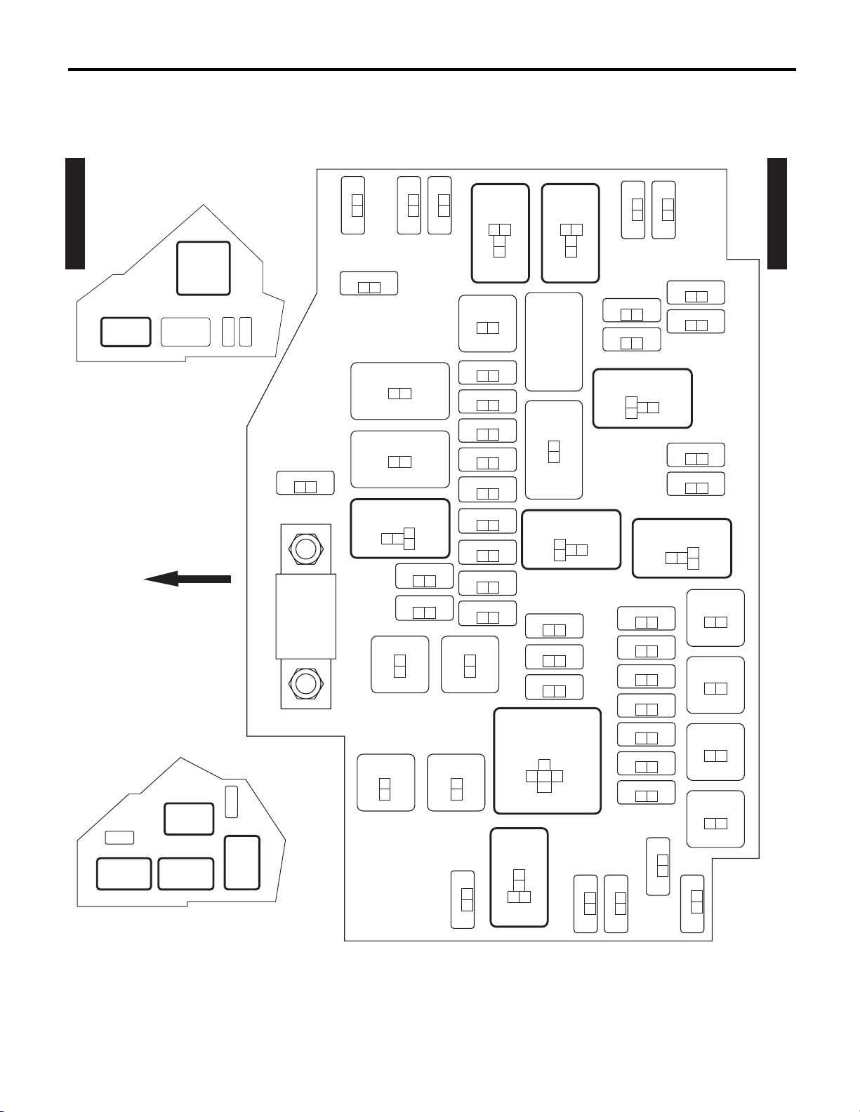
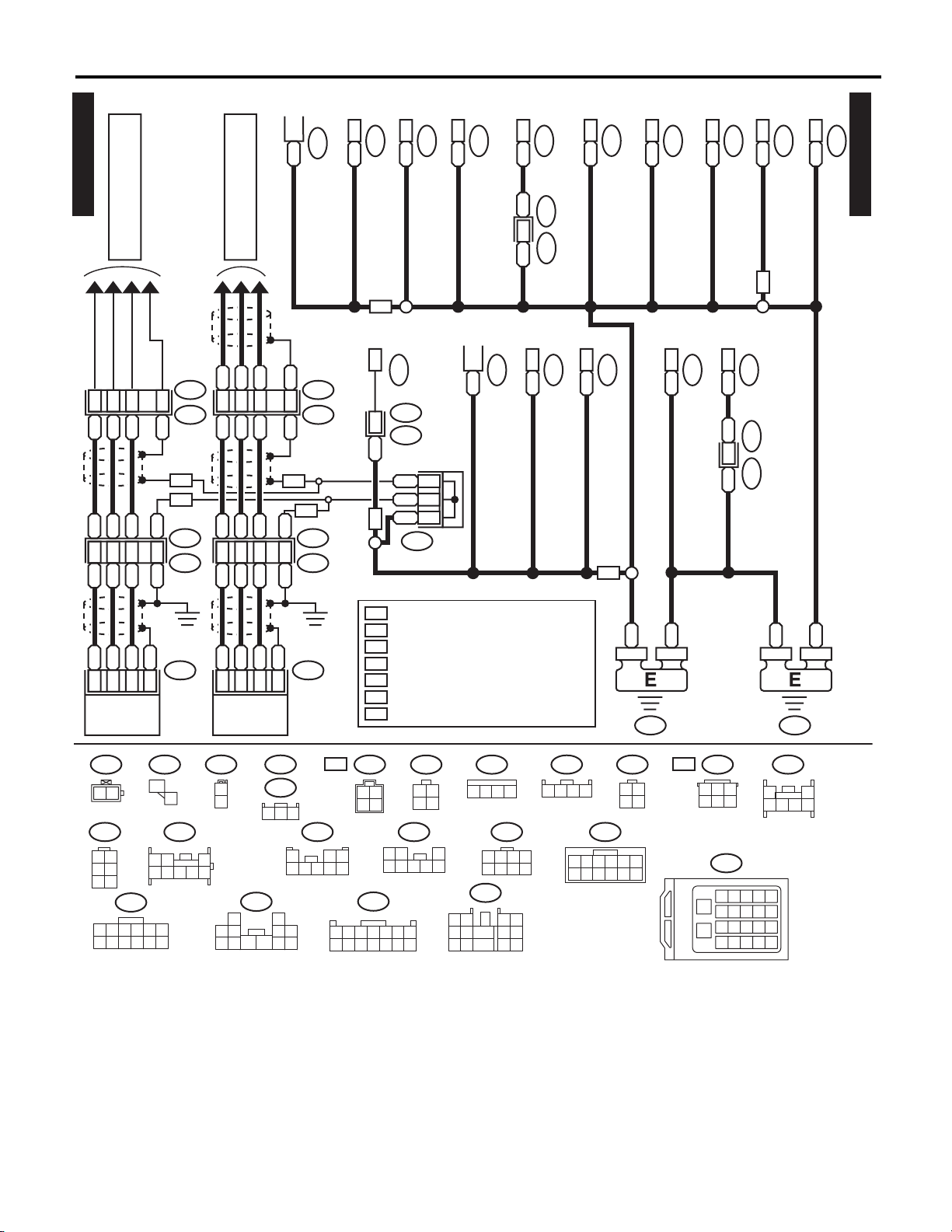
3. Power Supply Circuit
A: WIRING DIAGRAM
• Engine room side
Power Supply Circuit
WIRING SYSTEM
P-SUP-01
MAIN FAN
DAYTIME
RUNNING
LIGHT RELAY
A/C RELAY HOLDER (3.6 L MODEL)
FRONT
DAYTIME
RUNNING
LIGHT RELAY
SUB FAN
RELAY
A/C RELAY HOLDER (2.5 L MODEL)
MAIN FAN
RELAY 1
RELAY
MAIN
FAN
RELAY
2
BAT
ALT
No. 39
12
MAIN SBF
12
No. 38
No. 20
12
TAIL & ILLUMI
SBF-13
SBF-3
12
SBF-4
12
RELAY
3
1
SBF-11
21
12
No. 33
2
4
No. 34
No. 35
12
12
12
12
No. 32
SBF-12
SBF-9
SBF-10
21
12
12
No. 37
HORN
RELAY
21
No. 11
21
No. 12
21
No. 13
21
No. 14
21
No. 15
21
No. 16
21
No. 17
21
No. 18
21
No. 19
21
4
2
3
1
F. FOG
RELAY
1
3
4
2
H/L LO
RELAY
2
4
3
1
SBF-2
12
POWER WINDOW
RELAY
2
3
1
4
No. 27
12
No. 28
12
No. 29
12
WIPER
RELAY
3
4
2
1
No. 31
21
No. 25
No. 26
No. 30
No. 24
21
21
H/L HI
RELAY
4
2
21
12
3
No. 3
21
No. 4
21
No. 5
21
No. 6
21
No. 7
21
No. 8
21
No. 9
21
1
No. 10
12
No. 23
R. DEF
RELAY
1
21
No. 1
12
No. 2
12
No. 21
12
No.22
12
4
3
2
No. 36
SBF-5
12
SBF-6
12
SBF-7
12
SBF-8
12
12
M/B
WI-25393
P-SUP-01
WI-15
Page 14

WIRING SYSTEM
• Passenger room side
P-SUP-02
Power Supply Circuit
F/B FRONT SIDE
No. 27
No. 20
No. 13
No. 6
No. 28
No. 21
No. 14
No. 7
No. 29
No. 22
No. 15
No. 8
No. 30
No. 23
No. 16
No. 9
No. 31
No. 24
No. 17
No. 10
No. 32
No. 25
No. 18
No. 11
No. 33
No. 26
No. 19
No. 12
F/B BACK SIDE
P-SUP-02
No. 1
No. 2
No. 3
No. 4
No. 5
MAIN
RELAY
IG
RELAY
RELAY HOLDER
A/F,
OXYGEN
SENSOR
RELAY
ELECTRIC
THROTTLE
CONTROL
RELAY
FUEL
PUMP
RELAY
IG 2
RELAY
ACC
RELAY
WI-24813
WI-16
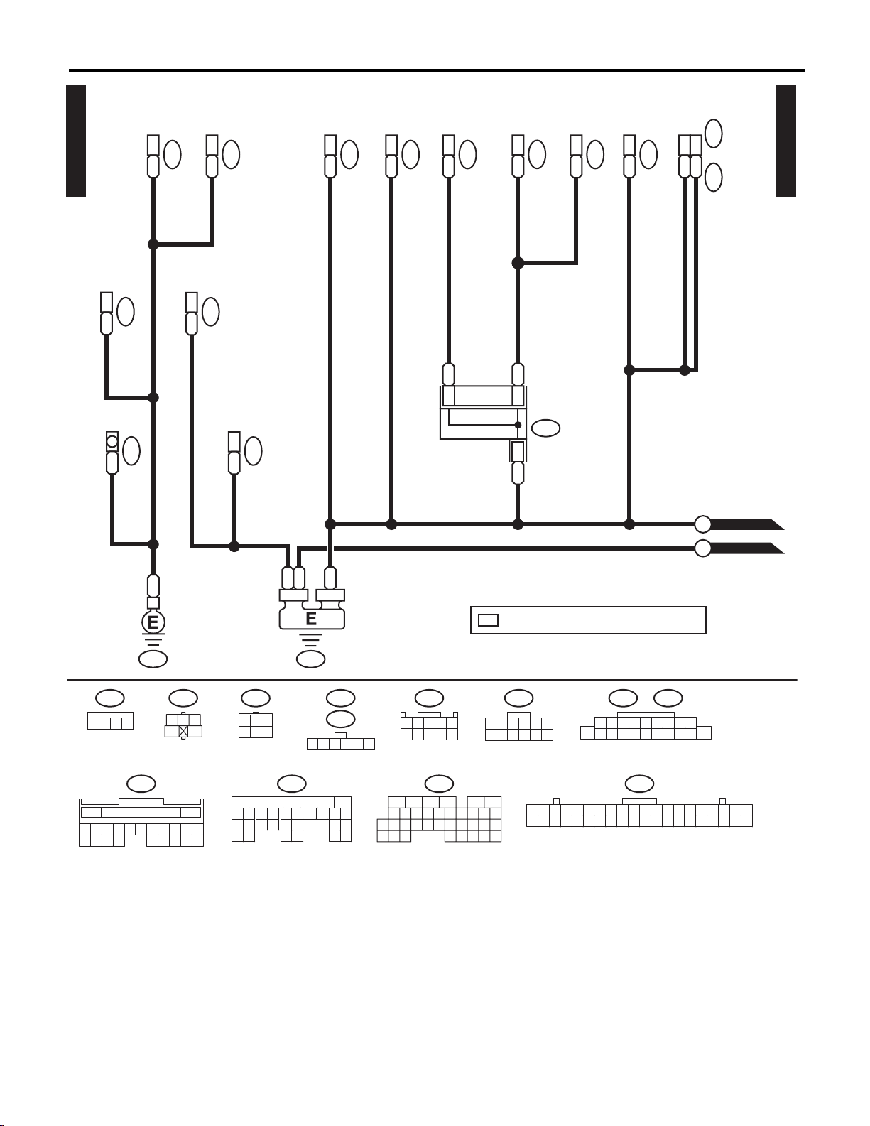
Page 15

Power Supply Circuit
WIRING SYSTEM
P-SUP-03
GENERATOR
B515
BATTERY
W
2
B471
W
WRWR
M/B
W
MAIN SBF 120A
1
1
No. 2 7.5A
21
SBF-8 50A
SBF-6 40A
2
No. 9 30A
2
1
2
1
No. 6 25A
2
E6
1
No. 5 15A
SBF-7 50A
2
: EXCEPT FOR 3.6 L MODEL
E6
E6
1
1
1
1
1
No. 4 15A
No. 8 25A
No. 7 25A
2
2
SBF-5 40A
2
2
2
P-SUP-07
A
P-SUP-04
B
GOr
1
2
3
REAR DEFOGGER RELAY
4
1
GB
P-SUP-04
C
P-SUP-04
D
1
2
WIPER RELAY
3
4
1
1
1
P-SUP-03
BATTERY CURRENT
CURRENT FROM IGNITION
SWITCH "IG" TERMINAL
CURRENT FROM IGNITION
SWITCH "ACC" TERMINAL
OTHER
(LIGHT GREEN)
B471
31 2
B478
3 421 5
No. 29 30A
No. 28 10A
No. 22 25A
2
L
WR
MB-1
RY
MB-2
RB
MB-3
G
GL
MB-4
Y
MB-6
RW
MB-7
W
RL
MB-8
VG
MB-9
GW
MB-10
No. 27 15A
2
2
2
B
G
GB
P-SUP-06
E
P-SUP-07
F
P-SUP-07
G
P-SUP-06
H
B
J/C
2
B478
REF. TO GND
MB-12
MB-11
[GND-02]
WI-25394
WI-17
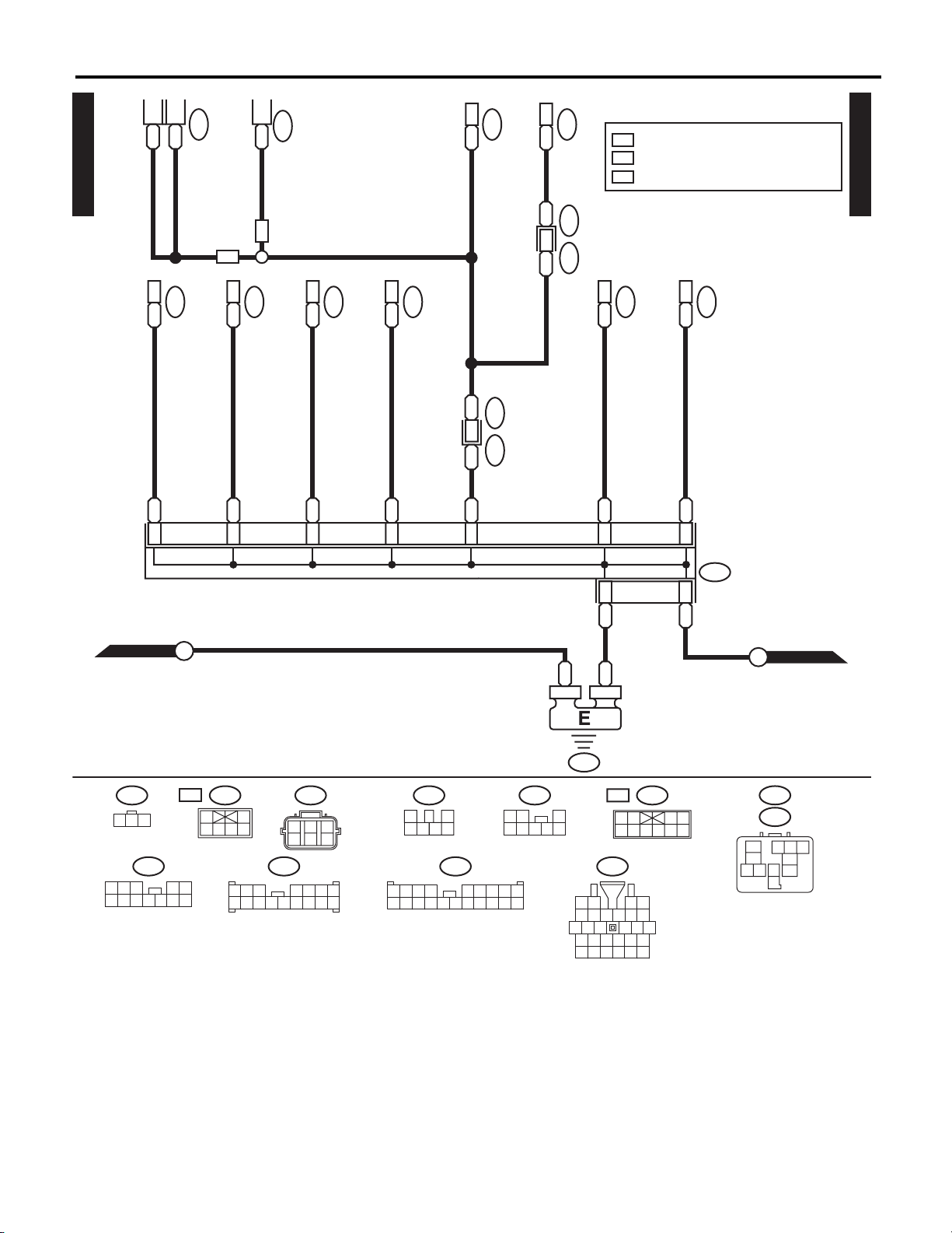
Page 16

WIRING SYSTEM
P-SUP-03
P-SUP-04
Power Supply Circuit
P-SUP-06
I
P-SUP-07
B
: EXCEPT FOR MT MODEL
EM
1
: MT MODEL : BR
*
GB
GB
EXCEPT FOR MT MODEL : GR
J
P-SUP-04
P-SUP-03
C K
D
1
FRONT FOG LIGHT RELAY
1
No. 31 10A
2
LR
3
1
No. 30 10A
2
L
2
4
VY
1
No. 10 10A
2
LR
1
No. 19 20A
2
WR
1
No. 11 20A
2
WL
1
SBF-9 30A
SBF-11 30A
2
W
1
SBF-10 30A
2
WG
1
2
BW
1
2
3
BW
4
1
EM
*
POWER WINDOW RELAY
TAIL & ILLUMINATION RELAY
1
No. 35 10A
2
BL
1
3
1
No. 34 10A
2
V
2
4
LY
BW
HEADLIGHT RELAY HI
1
No. 26 10A
2
RL
1
3
1
No. 25 10A
2
RG
2
4
L
LY
HEADLIGHT RELAY LOW
1
No. 24 15A
2
BrR
No. 23 15A
1
3
1
2
BrW
2
4
LY
L
M
P-SUP-05P-SUP-03
LG
P-SUP-06
P-SUP-06
MB-13
B517
12
MB-14
MB-15
MB-16
MB-17
MB-18
MB-19
MB-20
GR
GR
MT MT
GR
1
2
B517B516
EM
B
MB-25
MB-24
MB-23
MB-22
MB-26
MB-27
MB-28
MB-29
MB-30
N
MB-31
P-SUP-05
WI-30960
WI-18
Page 17

Power Supply Circuit
WIRING SYSTEM
P-SUP-05
P-SUP-04
: NON-TURBO MODEL
NA
1
: MT MODEL : B478
*
EXCEPT FOR MT MODEL : B491
2
: MT MODEL : BR
*
EXCEPT FOR MT MODEL : B
3
: MT MODEL : 4
*
EXCEPT FOR MT MODEL : 1
K
HORN RELAY
1
No. 32 7.5A
2
1
3
1
No. 33 7.5A
2
REF. TO ENGINE
ELECTRICAL SYSTEM
[E/G(NA)-05]
[E/G(TB)-13]
[E/G(H6)-14]
1
No. 12 7.5A
2
AT
1
No. 17 10A
2
CVT
1
No. 1 20A
2
NA
2
4
1
SBF-2 80A
No. 18 15A
2
1
2
1
No. 16 15A
2
1
No. 15 15A
2
1
No. 14 15A
2
1
No. 13 15A
2
1
No. 20 20A
2
P
1
No.36
2
DELIVERY (TEST) MODE FUSE M/B FUSE
W
1
No. 38 7.5A
2
REF. TO CVT
CONTROL SYSTEM
[CVT-05]
P-SUP-05
P-SUP-04
N
B478
B491
REF. TO GND
[GND-02]
3 421 5
RG
MB-33
R
MB-34
BG
2
*
J/C
3
*
1
*
MB-32
W
MB-35
WB
MB-36
W
MB-37
R
MB-38
G
MB-39
L
MB-40
WG
MB-41
W
MB-42
WR
MB-43
WR
MB-44
BY
GY
REF. TO ENGINE
ELECTRICAL SYSTEM
[E/G(NA)-05]
[E/G(TB)-13]
[E/G(H6)-14]
REF. TO CVT
CONTROL SYSTEM
[CVT-05]
WI-30961
WI-19
Page 18

WIRING SYSTEM
Power Supply Circuit
P-SUP-03
P-SUP-04
P-SUP-04
P-SUP-04
P-SUP-06
P-SUP-03
F/B
A:
i5
B:
i152
C:
B52
E:
B158
F:
B159
L
E6
No. 1 15A
M
H
E
L
I
No. 8 15A
No. 9 15A
No. 17 15A
BW
E4
No. 3 20A
GB
F6
No. 29 20A
FB-7
BL
C5
GB
E8
No. 2 20A
GB
E7
No. 15 20A
P-SUP-06
G
F9
E3
B4
LOr
FB-1
E:
B158
152
12 13 14 15 16 17 18 19 20 21 22 23 24
34
678
567
3412 89
E1
C23
LB
WL
FB-3
FB-2
F:
12 43
596
B52C:
10 11
C15
LW
B159
78
(BROWN)
A9
WG
FB-5
C2
G
FB-8
A:
1234 56789
10 11 12 13 14 15 16 17 18 19 20
E2
A4
B13
A11
BL
LB
LW
LW
FB-9
FB-10
REF. TO
CLEARANCE LIGHT
& ILLUMINATION
i5
32 4 5 76 98
A7
B10
BL
GY
FB-13
LIGHT SYSTEM
[ILLUMI-02]
i152
B:
14
13121110 1716
15
B6
A13
GW
FB-14
1918120
B2
F5
GOr
FB-15
B15
G
FB-16
WI-25397
WI-20
Page 19

P-SUP-03
P-SUP-03
P-SUP-07
Power Supply Circuit
WIRING SYSTEM
IGNITION SWITCH
B72
F
G
W
Y
G
L
WL
WG
OFF ACC
3
5
1
4
2
6
STON
P-SUP-07
P-SUP-04
P-SUP-03
A
J
No. 7 7.5A
B11
WL
No. 22 15A
No. 33 7.5A
D3
GY
L
F3
GOr
C1
GOr
WG
F2
No. 21 7.5A
D1A3D8
WL
F/B
A:
i5
B:
i152
C:
B52
D:
B152
E:
B158
F:
B159
G:
AB35
H:
i193
B
B
J/C
1
B491
Y
G
F7
E5
IG 2 RELAY
ACCESSORY RELAY
No. 6 7.5A
C19
WL
A10
Y
No. 13 20A
D6
No. 20 10A
B14
Y
No. 24 15A
A19
YV
A17
YR
No. 31 7.5A
C7A1D7
YR
No. 4 7.5A
A5
GY
G
F8
C8A6D9
B18
GY
No. 11 7.5A
OrG
No. 5 7.5A
No. 18 7.5A
C16
GL
No. 12 15A
A20A8C24
GR
GR
BrW
H1
No. 19 7.5A
G1
D4
Br
No. 25 15A
H2
GY
No. 26 7.5A
G2
GY
C11
GB
G: H:
AB35
12
A:
1234 56789
10 11 12 13 14 15 16 17 18 19 20
FB-17
i193
12
i5
FB-18
FB-19
FB-20
FB-21
B491
FB-24
FB-22
3 421 5
32 4 5 76 98
FB-26
B72
13
2
456
B:
i152
14
13121110 1716
15
FB-27
FB-28
152
1918120
WI-21
FB-29
E:
B158
678
FB-40
FB-32
FB-31
FB-30
34
12 13 14 15 16 17 18 19 20 21 22 23 24
FB-33
B159
F:
12 43
596
78
C:
B52
567
3412 89
FB-34
FB-35
10 11
FB-37
FB-38
FB-39
D:
21
ST-1
B152
REF. TO GND
ST-2
[GND-02]
(GRAY)(BLACK) (BROWN)
43
10
9
8765
WI-30595
Page 20

WIRING SYSTEM
Power Supply Circuit
No. Load
MB-1 VDC CM
MB-2 VDC CM
MB-3 Audio
Navigation unit
Audio amplifier (McIntosh)
MB-4 Blower motor relay
MB-6 Main fan relay 1
MB-7 Sub fan relay
MB-8 Mirror heater relay
Rear defogger
MB-9 Body integrated unit
MB-10 Front wiper motor
Combination switch (wiper)
MB-11 Front washer motor
MB-12 Rear washer motor
MB-13 Front fog light RH
MB-14 Front fog light LH
MB-15 Body integrated unit
MB-16 Body integrated unit
Clock
Audio
Navigation unit
Luggage room light
Door step light LH
Door step light RH
Trunk room light
Spot map light
Room light
Vanity mirror light LH
Vanity mirror light RH
TPMS & keyless entry CM
Puddle light LH
Puddle light RH
Rearview mirror (with rearview display)
MB-17 Body integrated unit
MB-18 Sunroof motor assembly
MB-19 EPB CM
MB-20 Power seat LH
Power seat RH
MB-22 Front combination light LH (clearance light)
Front combination light RH (clearance light)
F/B
No. Load
MB-23 Satellite switch illumination
AT select lever illumination
Illumination control switch
Remote control mirror switch
Lower cover switch
Glove box light
Hill hold switch
Audio
Navigation unit
Seat heater switch (power seat)
Shower light
A/C control panel
EPB control switch
MB-24 Body integrated unit
Daytime running light relay
MB-25 Body integrated unit
MB-26 Front combination light RH (headlight)
MB-27 Front combination light LH (headlight)
MB-28 Body integrated unit
MB-29 Front combination light RH (headlight)
MB-30 Front combination light LH (headlight)
MB-31 Body integrated unit
MB-32 Horn
MB-33 Horn
MB-34 Body integrated unit
Horn switch
MB-35 Main fan relay
MB-36 Body integrated unit
Key warning switch
Turn signal and hazard unit
MB-37 Main relay
MB-38 A/F, oxygen sensor relay
MB-39 IG relay
MB-40 Electronic throttle control relay
MB-41 Fuel pump relay
MB-42 ECM
Data link connector
MB-43 TCM
MB-44 Self shut relay
TCM
ST-1 Inhibitor relay
Starter relay
ST-2 Starter relay
FB-1 Trailer connector
FB-2 Stop light and brake switch
Stop light register
FB-3 Seat heater relay
FB-5 Power window main switch
FB-7 Power window circuit breaker
FB-8 Front power window sub-switch
WI-22
Page 21

Power Supply Circuit
WIRING SYSTEM
No. Load
FB-9 Wiper deicer relay
FB-10 Mirror heater relay
FB-13 Rear power window sub-switch LH
FB-14 Rear power window sub-switch RH
FB-15 Body integrated unit
FB-16 Rear wiper motor
FB-17 Combination meter
Body integrated unit
Impact sensor
EPB control switch
A/C CM
FB-18 Security CM
FB-19 Remote control mirror switch
Seat heater relay
Rearview mirror (without rearview display)
FB-20 Rear accessory power supply socket
FB-21 Front accessory power supply socket
FB-22 Audio
Navigation unit
FB-24 Body integrated unit
A/C control panel
A/C CM
FB-26 Impact sensor
Wiper deicer relay
A/C control panel
Navigation unit
Rearview mirror (with rearview display)
Sunroof motor assembly
TPMS & keyless entry CM
FB-27 ECM
Data link connector
Stop light and brake switch
Clutch switch
FB-28 Turn signal and hazard unit
FB-29 Inhibitor switch
Back-up light switch
Back-up light relay
FB-30 Combination meter
Clock
FB-31 A/C CM
Body integrated unit
Light control sensor
FB-32 TCM
ECM
Fuel pump relay
Ignition coil No. 1 (turbo model)
Ignition coil No. 2 (turbo model)
Ignition coil No. 3 (turbo model)
Ignition coil No. 4 (turbo model)
No. Load
FB-33 Hill hold switch
EPB CM
FB-34 Airbag CM
FB-35 Main fan relay 1 (Except for 3.6 L model)
Main fan relay 2 (Except for 3.6 L model)
Main fan relay (3.6 L model)
FB-37 VDC CM
Steering angle sensor
FB-38 Blower motor relay
Intake door actuator
FB-39 Sub fan relay
FB-40 Occupant detection control module
WI-23
Page 22

WIRING SYSTEM
4. Ground Circuit
A: WIRING DIAGRAM
1. CHASSIS GROUND
Ground Circuit
2
B
GND-01
FRONT WIPER MOTOR
B
1
B8
FRONT
2
B
SWITCH
BRAKE FLUID LEVEL
3
4
B
B
COMBINATION LIGHT RH
1
BG
OD
BG
3
B16
2
BR
BR
2
2
B321
B
HOOD SWITCH
2
B487
1
B
FRONT FOG LIGHT RH
B
4
B488
B
KEYLESS BUZZER
B
5
J/C
B490
B483
2
B473
B
MAIN FAN MOTOR
TB
FRONT FOG LIGHT LH
B
1
B497
BY
5
J/C
B479
AIRBAG CM
25
B
1
BY B
26
BW
2
BY BW
BY
3
1
BY
STEERING ANGLE SENSOR
AB1 AB6B495
A1
B31
UNIT
BY
BODY INTEGRATED
GND-02
A
B231
BY
SECURITY CM
B281B:B280A:
1
BY
B518
GND-01
J/C
B491
1
B473
B
MAIN FAN MOTOR
NA
1
B474
B
25
B
B
3
2
19
B
MAIN FAN RELAY 2
19
B220
B
FUEL PUMP RELAY
E2
B
4
(LIGHT GRAY)
B16
1
2
AB1
21
2
1
98
18 2719 20 21 22
28 29 3332 3430 31
:
NA
B321
21
(GRAY)
43
8765
10
9
B280A:
34567
1210
1311 1716
1514
23
24
2625
B473
21
(BLACK)
B518
5341 2
1513 1411 12 2018 1916 17
12
28 29 30 31
TB
896 7
98
2120
:
B473
12
10
1
B281B:
34567
2322 24 25
151413121110 16
32 33
(DARK GRAY)
B474
B488
21
3245768
1918
17
26
27
34 35
NA
TB
25
B490
(BROWN)
(BROWN)
RELAY HOLDER
B220
9
10
1 2
1211
: 2.5 L MODEL
(BLACK)
17
13
16
18 20 21
15
14
19
B8
12453
E2
OD
(LIGHT GRAY)
8
A/C RELAY HOLDER
: EXCEPT FOR 2.5 L NON-TURBO MODEL: NON-TURBO MODEL
: WITHOUT DAYTIME RUNNING LIGHT: TURBO MODEL
97
12
13
B491
B231
B497
4351
6
15141110
B479
B483
5341 2
3 421 5
(BLACK) (YELLOW)
2
18
19
16
2221
2017
1234
5678
24
23
B487
AB6
(LIGHT GRAY)
2625 27 28 29
WI-29306
910785 63 412
2015 1613 14 18 191711 12
3021 22
WI-24
Page 23

Ground Circuit
WIRING SYSTEM
(WIPER)
GND-02
COMBINATION SWITCH
2
M/B
(POWER WINDOW RELAY)
EM
GR
1
GR
B54A:
BY
1
DAYTIME RUNNING
OD
6
B497
BW
LIGHT RELAY
RADIATOR FAN CU
MT
BW
3
2
B
*
MT
B70
(LIGHTING)
COMBINATION SWITCH
BGR
B517B516
2
GND-01
7
12
B
B
F/B
D8
B
A
B71
B152D:
REMOTE
ENGINE START CM
3
B180
B
B
1
8
4
2
BYBYBY
AT SELECT LEVER
B116
FRONT
BY
4
10
TCM
A23
A22
B68
BY
ROLL CONNECTOR
(PADDLE SHIFT SWITCH)
1
4
3
B
B
BW
COMBINATION LIGHT LH
2
B
SENSOR
WASHER LEVEL
B
5
B491 B478
5A
2
BY
B396
B477
M/B
BY
BY
B
(WIPER RELAY)
B
2
2
B5
BW
LIGHT RESISTOR
DAYTIME RUNNING
: 3.6 L MODEL
1
B
4
BB
H6
1
4
H6
: EXCEPT FOR 3.6 L MODEL
E6
F106
*
: WITHOUT DAYTIME
OD
RUNNING LIGHT
: 5AT MODEL
5A
: EXCEPT FOR MT MODEL
EM
: 3.6 L MODEL : B
1
*
MT MODEL : BR
: MT MODEL : BR
2
*
B504 F135
EXCEPT FOR MT MODEL : GR
1
B506
B
COMPRESSOR SOLENOID
B
5
J/CJ/C
13
VDC CM
B
B
GND-02
B310
(LIGHT GRAY)
B5
12
21
2
1
14
15 16 17 18 19 20 21 22 23 24 25
B396
12
(GRAY)
B152D:
43
10
9
8765
B310
785634
(BROWN)
89
(BLACK)
9
10
B506 B504
B517
12
9
10
12
98
2120
28 29 30 31
B68
2322 24 25
B71
4567312
11 12 13 1410
11 12
21
13
26
(LIGHT GRAY)
F106
123
78563412
15 1613 1411 12
B54A:
34567
151413121110 16
32 33
1918
17
26
27
34 35
B180
341 2
B70
2198
3 4 5 76
1110
16
15141312
12
34
H6
1817
7
85 6
9
A/C RELAY HOLDER
GV
(LIGHT GRAY)(BLACK)(LIGHT GRAY)
3
7856
:
B497E6
4351
6
97
15141110
B477
1234
5678
(BLACK)(BLACK)
2
18
19
16
2017
2221
B478
B491
3 421 5
:
B497
1
3
2
4
12
151617
131411
10
18
B116
1 2
4
8
12
13
A/C RELAY HOLDER
WI-29307
WI-25
Page 24
WIRING SYSTEM
Ground Circuit
GND-03
A10
i26
AUDIO
B
A:
B
GROUND
AUDIO BRACKET
NAVIGATION UNIT
i29
A10
B
i144A:
POWER TRANSISTOR
4
B
(AUTO A/C)
5
i149
B
AUX INPUT TERMINAL
i183
(MANUAL A/C)
BLOWER FAN SWITCH
i10
6
CLOCK
BY
i59
B6
BY
NAVIGATION UNIT
BY
1
*
(MANUAL A/C)
A/C CONTROL PANEL
11
BY
BY
1
1
BY
*
J/C
*
i145B:
i97
i88
(AUTO A/C)
A/C CONTROL PANEL
12
BY
i88
A6
A/C CM
BY
i80A:
C1
D29
BY
BY
BODY INTEGRATED UNIT
B
C
i84C: i171D:
GND-04
GND-05
GND-03
39
BY
COMBINATION METER
1
i15
B
B
GR
i97
43
21
123456
98
7
1918 2120
i80A:
i183
4
151413121110
2322 24 25 26
B
B
BY
: TERMINAL No. OPTIONAL ARRANGEMENT
1
*
GB-5
(GREEN)
i15
321
5
1716
3412
56
i171
D: i84C:
1234567
98
22
20 21
1918
26
28 29
27
i145B:
i149
123456
151413121110 1716
24 25
23
30 31
17
28 29 30
i59
3421
78
6
1 234
98
7
1918 2120
5
9
10
2322 24 25 26
31 32 33 34 35
56
151413121110 16
27
i88
10
2625 27
132 4
65341 2
11 12
91078
21 22 23 24 28 29 30 31 32 33 34 35 36 37 38 39 40
9107856341 2
5 76 98
1514131211 1716
i10
11 12
i144i26 A:A:
20
1918
15 1613 14 17
1918 20
WI-29308
WI-26
Page 25
Ground Circuit
WIRING SYSTEM
GND-04
OUTER MIRROR ASSY LH
SEAT HEATER RELAY
OUTER MIRROR ASSY LH
C6
7
i6
B
REMOTE CONTROL MIRROR SWITCH
B
1
*
3
B
EC
D5
1
B
(VDC OFF)
LOWER COVER SWITCH
B
1
*
i162
2
i162
B
(TRUNK LID OPENER)
LOWER COVER SWITCH
B
1
*
FRONT POWER WINDOW
5
B
MOTOR LH
3
BBB
1
A3
D13
POWER WINDOW
D84i101
*
D7A:
B
MAIN SWITCH
BB
D147D145
5
: C6 MODEL
C6
: EXCEPT FOR C6 MODEL
EC
: TERMINAL No. OPTIONAL ARRANGEMENT
1
*
9
i161
B
MIRROR HEATER RELAY
B
1
*
1
*
B
7
i170
B
TURN SIGNAL &
HAZARD MODULE
B
1
*
J/C
i82
1
*
B
GND-04
5
10
D5
B
B
9
i160
B
B
1
*
GND-03
D7A:
312
i82
132 4 5
98
76
B
D5 D5
EC
12
3456
i6
121110
31 2
9
10
D13
3
42156
1311 12
14 1615
(DARK GRAY)
78564
i162
21
3456
D145
32 4 5 76 98
151413121110 1716
1 2
4
1918120
i170
3
7856
B
BY
GB-6
::
C6
34 12
10
978 6
D84
1 324
5 76 98
17
1514131211
1918 20 21 22
2524 26 27 2823
10
16
GND-05
D
i160
1
2
34
i161
978
10
5
11
6
5
WI-29309
WI-27
Page 26

WIRING SYSTEM
Ground Circuit
10
G
GND-05
SUNROOF MOTOR ASSY
4
BG
BB
4
B
1
*
GND-04
GND-03
R75
R74R55
R50i157
VANITY MIRROR
ILLUMI. LIGHT RH
D
C
2
B
FRONT ACCESSORY
R51
VANITY MIRROR
ILLUMI. LIGHT LH
1
i24
B
POWER SUPPLY SOCKET
B
1
*
2
R54
B
ROOM LIGHT
2
i187
B
WIPER DEICER
B
1
*
1
*
B
1
R52
B
(WITHOUT
REARVIEW
REARVIEW MIRROR
7
i188
B
IMPACT SENSOR
B
1
*
2
B
DISPLAY)
OUTER MIRROR ASSY RH
R387
SPOT MAP LIGHT
5
10
B
B
C6
BB
D83i76
3
B
1
*
5
B
R353
D15
3
D15
B
OUTER MIRROR ASSY RH
EC
A5
D125A:
B
PASSENGER'S
DOOR LOCK SWITCH
FRONT POWER WINDOW
B2
D17B:
B
SUB-SWITCH
BB
D146D144
3
1
B
GLOVE BOX ILLUMI. LIGHT
B
1
1
B
i88
(AUTO A/C)
A/C CONTROL PANEL
1
B
(CONSOLE BOX)
POWER SUPPLY SOCKET
B
1
*
J/C
2
B
i189
i100
i88
GND-05
5
i23
B
(MANUAL A/C)
A/C CONTROL PANEL
REAR ACCESSORY
B
*
1
*
*
i23
C6
10
10
21
D15
:
34 12
978 6
132 4
: C6 MODEL
C6
: EXCEPT FOR C6 MODEL
EC
: TERMINAL No. OPTIONAL ARRANGEMENT
1
*
i24
i189
1
5
R75
5 76 98
1514131211 1716
i187
R54
12
2
R353
21
20
1918
21
43
8765
10
9
R52R51 R55
D144
9
786
R387
31 2
321
53412
11 12
10
EC
:
D125A:
3 421
i88
11 12
91078
65341 2
12345
i100
132 4 5
9876
D15
12
3456
i157
2134
121110
610875 9
1211 1413 1615
D17B:
312
78564
1 324
5 76 98
17
i188
D83
1514131211
1918 20 21 22
2524 26 27 2823
3412
7856
10
16
WI-29310
WI-28
Page 27

Ground Circuit
WIRING SYSTEM
GND-06
REF. TO REARVIEW CAMERA
SYSTEM [RVCAM(S)-01]
LY
WL
8
6
R
W
LOr
7
B
Y
9
SB
REAR POWER WINDOW
R24
R60
(WITH REAR SPOILER)
HIGH-MOUNTED STOP LIGHT
2
D31
B
SUB-SWITCH RH
1
SB
Y
BY
2
B
R336
2
R66
B
LICENSE PLATE LIGHT LH
FRONT DOOR SWITCH RH
BYB
R13D28
J/C
1
*
1
*
1
*
3
BY
2
R76
R12
R77
B
LICENSE PLATE LIGHT RH
3
BY
REAR DOOR SWITCH RH
3
BY
LIGHT RH
REAR COMBINATION
SWITCH
ACTUATOR &
TRUNK LID LOCK
R16
SEAT HEATER SWITCH RH
R26
2
B
6
BY
R186
R45
1
R350
B
(TAIL LIGHT)
REAR FINISHER LIGHT LH
4
B
B
FUEL PUMP ASSY
6
(FUEL LEVEL SENSOR)
BY
SD
(TAIL LIGHT)
REAR FINISHER LIGHT RH
R58
R57
R15
SEAT HEATER RH
1
B
BBY
5
SD
1
BY
R351
R60R24
OB
R44
LIGHT RH
REAR COMBINATION
3
BY
R26
LUGGAGE ROOM LIGHT
GND-07
E
GND-07
F
1
BY
R347
GND-06
R
2
REARVIEW
CAMERA
R66
2 1
R45
1
2
3456
B
W
4
3
(BROWN)
SB
1
R330
R76
R77
1
2
R58
12
34
56
R12
R16
123
4
OA
A10
R386
Or
AUDIO AMPLIFIER
R186
R350
R351
312
D31
3
21
785 6
R13
1 2
4
A:
R347
7856
3
BY
1
Or
31 2
R383
R384
:
R26
OB
423
R60
12345
6789
R44
1
10
R383
12
34
1
3
BY
GB-7
4
R57
98
B
65
1110
: SEDAN MODEL
SD
: OUTBACK MODEL
OB
: EXCEPT FOR NORMAL AUDIO MODEL
OA
: TERMINAL No. OPTIONAL ARRANGEMENT
1
*
341 2
A:
5341 2
1715 1613 14 2220 2118 19
SD
R386
896 7
R330
12
34
2
7
R336
:
R26
3412
56
10
1211
2423
WI-29311
WI-29
Page 28

WIRING SYSTEM
Ground Circuit
GND-07
2
D91
B
(BACK-UP LIGHT)
REAR FINISHER LIGHT LH
1
D39
B
HIGH-MOUNTED STOP LIGHT
1
B
(TAIL LIGHT)
REAR FINISHER LIGHT LH
B
3
B
OB
D134
D34R38
REAR WIPER MOTOR
R122
REAR GATE OPENER BUTTON
POWER SEAT RH
6
B
1
B
D77
REAR DEFOGGER
R109
2
D89
B
GND-07
2
D87
B
(BACK-UP LIGHT)
REAR FINISHER LIGHT RH
4
D43
B
2
D44
B
LICENSE PLATE LIGHT
2
R174
B
REAR DEFOGGER
SD
1
D139
B
(TAIL LIGHT)
REAR FINISHER LIGHT RH
6
R58
GY
(FUEL PUMP)
(2.5 L MODEL)
FUEL PUMP ASSY
GYB
R57
2
R15
NA
4
2
B
B
REAR GATE LOCK
ACTUATOR & LATCH SWITCH
C6
C7
R317C:
B
B
AUDIO AMPLIFIER
OA
D47
5
B
FUEL PUMP CU
E2
GND-06
GND-06
D39
12
1
4
3
R57
98
F
E
: NON-TURBO MODEL
21
(BLACK)
NA
: EXCEPT FOR 2.5 L NON-TURBO MODEL
E2
: SEDAN MODEL
SD
: OUTBACK MODEL
OB
OA
: EXCEPT FOR NORMAL AUDIO MODEL
D43
1342
D47
3 421
4 356 2 1
R58D77
12
34
56
B
BY
GB-8
D44
2 1
2
7
65
1110
D87
D91
132 4 5
D89
R174
21
76
1
2
R317C:
98
D134
D139
12
121110
R109
D34
312
78564
9
1311 12
10
21
GB-11
R122
8765
B
43
10
9
WI-25405
WI-30
Page 29
Ground Circuit
WIRING SYSTEM
GND-08
REF. TO REARVIEW CAMERA
SYSTEM [RVCAM(ON)-01]
10311
LY
WL
LOr
LY
WL
LOr
2
3
4
B
R
W
Y
1
SB
4
SB
R340
R389
ON
ON
R330
R356
REF. TO REARVIEW CAMERA
SYSTEM [RVCAM(W)-01]
LY
WL
4
3
2
LY
WL
LOr LOr
LY
WL
LOr
2
3
4
B
R
W
1
BY
HIGH-MOUNTED STOP LIGHT
SB
R346
1
R348
SB
WN
WN
Y
R330
1
R356
SB
R19
REAR COMBINATION LIGHT LH
REARVIEW MIRROR
3
BY
(WITH REARVIEW DISPLAY)
3
R28
BY
FRONT DOOR SWITCH LH
SD
3
R90
R340
1
R389
BY
SB
Y
BY
ON
R336
3
J/C
*
*
*
R9
1
1
1
R22
BY
REAR DOOR SWITCH LH
3
BY
LIGHT LH
REAR COMBINATION
2
D25
B
SUB-SWITCH LH
BBY
REAR ACCESSORY
D22
1
R10
1
BY
POWER SUPPLY SOCKET (CARGO ROOM)
REAR POWER WINDOW
R28
R32
(MANUAL SEAT)
SEAT HEATER LH
8
BY
TRAILER CONNECTOR
1
BY
R41
R79
OB
6
R42
BY
9
B
POWER SEAT LH
SEAT BELT SWITCH LH
R341
SEAT HEATER SWITCH LH
(MANUAL SEAT)
2
BY
6
EPB CM
B
BB
12
R108
TPMS & KEYLESS ENTRY CM
R355
R354R342
5
BY
TP
R221
KEYLESS ENTRY CM
7
BY
R345
GND-08
R
W
312
REARVIEW
CAMERA
R19
12
R357
21
3 4
56
R221
91078
: WITHOUT NAVIGATION
ON
: WITH NAVIGATION
WN
: SEDAN MODEL
7856
OB
SD
: OUTBACK MODEL
OB
: WITH TPMS
TP
: TERMINAL No. OPTIONAL ARRANGEMENT
1
*
: SHIELD CONNECTOR
2
*
:
R28
423
3
R340
9
10
R41
12
1
34
R79
1 2
7856
4
78563412
13 1411 12
R336
341 2
R345D25
3
R354
(GRAY)
56
3 421
8
7
13 1411910
12
R346
341 2
3412
7856
7568
R90
3412
9
R356
12
34
(BLACK)
11
B
3
R108
1
2
R
W
3
1
REARVIEW
CAMERA
R341
1
4
10
9
837
SB
2
2
R9
R22
123
526
1211
R357
*
R10
1 2
4
B
SB
R357
2
*
R32
1
2
21
4
785 6
65341 2
11 12
1210
BY
GB-9
B
:
R28
SD
3412
56
R355
21543
6
87
1312 161514
17
1918 222120
B
BY
GB-10
R42
2
1
5643
1110
9
WI-29312
WI-31
Page 30

Ground Circuit
WIRING SYSTEM
2. ENGINE GROUND (2.5 L NON-TURBO MODEL)
GND-09
REF. TO ENGINE ELECTRICAL
SYSTEM [E/G(NA)-06]
IGNITION
COIL
No. 1
3
R
IGNITION
COIL
No. 2
E31
REF. TO ENGINE ELECTRICAL
SYSTEM [E/G(NA)-07]
IGNITION
COIL
No. 3
3
E32
R
3
R
E33
IGNITION
COIL
No. 4
3
R
E34
D3
LR
LR
37
BR
BL
36
BW
A:
B134
D:
B137
ECM
GND-09
R
40
BW
A6
BL
BW
35
BY
BP
34
BY
A4
R
B21
E2
A3
BW
D1
BP
REAR
OXYGEN
SENSOR
E10
21
G
3
OXYGEN (A/F)
(LIGHT GRAY)
E57
(BLACK)
321654
P
4
FRONT
SENSOR
L
E24 E10 E14E15E25 E57
3
E14
12
B
W
1
2
CRANKSHAFT
POSITION
SENSOR
B137D:
22
28 29
E15
151413121110 1716
23
(BLACK)
1234567
9
8
20 21
1918
27
26
L
G
1
2
CAMSHAFT
POSITION
SENSOR
(BLACK)
21
24 25
30 31
G
1
KNOCK
SENSOR
E31
E33
E32
E34
1
2
3
34567
2
1
98
18 2719 20 21 22
28 29 3332 3430 31
R
4
ELECTRONIC
THROTTLE
CONTROL
(BLACK)
(BLACK)
B134A:
1311 1716
1210
23
24
1514
W
6
2625
BR
BR
E24
(BLACK)
2431
13 14
12
23 24 25 26 27 28 29 30 31 32
34 35 36 37 38 39 40 41
42 43 44 45 46 47
48 49 50 51 52 53 54
BYRBY
BR
BW
GE
(BLACK)
B21
9
78563412
15 16 17 18 19 20 21 22
BY
E25
(DARK GRAY)
12
34
11
10
33
WI-29313
WI-32
Page 31

Ground Circuit
3. ENGINE GROUND (2.5 L TURBO MODEL)
WIRING SYSTEM
GND-10
REF. TO ENGINE ELECTRICAL
SYSTEM [E/G(TB)-07]
IGNITION
COIL No. 1
2
E31
LW
REF. TO ENGINE ELECTRICAL
SYSTEM [E/G(TB)-08]
IGNITION
COIL No. 2
2
LW
IGNITION
COIL No. 3
E32
REF. TO ENGINE ELECTRICAL
SYSTEM [E/G(TB)-09]
2
LW
E33
IGNITION
COIL No. 4
2
LW
E34
D1
BP
BP
34
BY
BW
35
BY
A:
B134
A3
BW
LR
BL
37
36
BYBYBY
ECM
D:
B137
GND-10
A6
BL
R
B21
40
E2
D3
LR
A4
R
L
3
REAR
OXYGEN
SENSOR
(LIGHT GRAY)
E10
21
B137D:
23456
17
9
8
26
22
20 21
1918
27
28 29
W
FRONT
OXYGEN (A/F)
SENSOR
151413121110
23
WR
E24 E10E25 E14
3
4
CRANKSHAFT
POSITION
SENSOR
E14
(BLACK)
12
2
1
34567
98
18 2719 20 21 22
28 29 3332 3430 31
1210
24 25
30 31
1716
W
WR
1
2
B134A:
1311 1716
23
(GRAY)
(GRAY)
1514
24
2625
KNOCK
SENSOR
E31
E32
1
2
3
L
1
E33
E34
L
4
ELECTRONIC
THROTTLE
CONTROL
(GRAY)
(GRAY)
34 35 36 37 38 39 40 41
42 43 44 45 46 47
G
E57
6
(LIGHT GRAY)
E24
21
43
B21
15 16 17 18 19 20 21 22
13 14
12
23 24 25 26 27 28 29 30 31 32
48 49 50 51 52 53 54
(BLACK)
78563412
LW
9
B
BYBYBYBBY
BY
GE
E25
(BLACK)
21
43
10
11
33
E57
321654
(BLACK)
WI-25408
WI-33
Page 32

WIRING SYSTEM
4. ENGINE GROUND (3.6 L MODEL)
Ground Circuit
IGNITION
COIL No. 1
GND-11
IGNITION
COIL No. 2
2
E31
WR
REF. TO ENGINE ELECTRICAL
SYSTEM [E/G(H6)-09]
2
WR
E32
IGNITION
COIL No. 3
2
WR
IGNITION
COIL No. 4
2
E33
REF. TO ENGINE ELECTRICAL
SYSTEM [E/G(H6)-08]
E34
WR
IGNITION
COIL No. 5
2
WR
E45
IGNITION
COIL No. 6
2
WR
E46
D3
LR
LR
37
LR
A:
A3
BW
BW
35
LR
B134
D5
BW
D:
B137
ECM
D1
A4
R
BP
R
BP
34
40
BPWRBP
A6
BL
BL
B21
36
E2
GND-11
W
Or
4
6
ELECTRONIC
THROTTLE
CONTROL
E10 E57
(LIGHT GRAY)
21
B21
15 16 17 18 19 20 21 22
13 14
12
23 24 25 26 27 28 29 30 31 32
34 35 36 37 38 39 40 41
42 43 44 45 46 47
48 49 50 51 52 53 54
E14
E48
1 2
(BLACK)
78563412
9
(BLUE)
(BLUE)
10
11
33
B
W
E10 E14 E48E57
1
2
CRANKSHAFT
POSITION
SENSOR
(GRAY)
(GRAY)
(GRAY) (GRAY)
KNOCK
SENSOR 1
E31
E32
E33
LR
2
(GRAY) (BLACK)
E34
(GRAY)
E45
E46
1
2
3
Lg
2
KNOCK
SENSOR 2
321654
Y
Y
B137D:
1234567
9
8
20 21
1918
26
27
22
28 29
151413121110 1716
24 25
23
30 31
LR
LR
BP
GE
1
98
18 2719 20 21 22
28 29 3332 3430 31
BP
WR
WR
B134A:
2
34567
1210
1311 1716
23
24
1514
2625
WI-25409
WI-34
Page 33

Ground Circuit
5. TRANSMISSION GROUND (AT MODEL)
WIRING SYSTEM
TCM
B55B:
GND-12
B12
P
P
8
BW
B12
T3
B13
OrB
OrB
14
BW
GND-12
B11
T4
1
9
17 18
B11
34
2
7856
11 12
10
15 1613 14
19 20
1234
7
1918 2120
17
28 29 30
B12 B55B:
(LIGHT GRAY) (LIGHT GRAY)
3421
6
785
98
BW
56
151413121110 16
2322 24 25 26
31 32 33 34 35
WI-35
BW
27
WI-25410
Page 34

Ground Circuit
WIRING SYSTEM
6. TRANSMISSION GROUND (CVT MODEL)
TCM
B54A:
GND-13
REF. TO STARTER
INHIBITOR
SWITCH
SYSTEM [ST(NA)-01]
REF. TO ENGINE
ELECTRICAL SYSTEM
[E/G(NA)-03]
WB
11
BW
9
P
R
N
T7
D
REF. TO BACK-UP
LIGHT SYSTEM
W
GL
12910
BY
WB
6
8
A5
W
[BACK/L-01]
W
BrY
3
G
BW
7
2
A18A9A22
L
R
G
L
R
G
2
1
8
L
P
W
5
3
4
A1
P
P
4
Br
1
A6
Y
P
Y
6
7
Y
B
312
PRIMARY
SPEED
SENSOR
AT1
GY
5
R
REF. TO CVT CONTROL SYSTEM
[CVT-05]
B12
T3
BW
A7
A14
B
Lg
B
Lg
201011
Lg
BW
Lg
BW
132
SECONDARY
SPEED
SENSOR
AT4
Br
GY
Br
A20
V
V
GY
7
12
P
LB
P
LB
132
FRONT
WHEEL
SPEED
SENSOR
AT5
P
13
BW
BW
GND-13
B11
T4
AT1
(GRAY) (BLACK) (BLACK)
(GRAY)
AT5
213
AT4
123
1
2345
6
T7
78
1
9
17 18
B11B12
34
2
7856
11 12
10
15 1613 14
19 20
1
2
15
14
(LIGHT GRAY) (GREEN)(LIGHT GRAY)
2
3
4
1
7
8
5
6
10
11
12
9
9
54
1817316 19
6
B54A:
879
2120 221023
122511
13
24
26
WI-25411
WI-36
Page 35

5. Airbag System
A: WIRING DIAGRAM
FB-27
F/B FUSE NO. 4
(IG)
MB-42
M/B FUSE NO. 12
(B)
FB-30
F/B FUSE NO. 5
(IG)
Airbag System
TO POWER SUPPLY CIRCUIT
WIRING SYSTEM
FB-34
F/B FUSE NO. 25
(IG)
A/B-01
DATA LINK
CONNECTOR
8
GY
16
W
7
VR
4
BL
5
BL
B40
GY
REF. TO ENGINE
ELECTRICAL SYSTEM
[E/G(NA)-05]
[E/G(TB)-06]
[E/G(H6)-05]
W
VR
3
VR
REVERSE
CIRCUIT
AIRBAG
WARNING
LIGHT
BrW
BrW
19
BrW
8
E5
COMBINATION
METER
i10
PASSENGER'S
AIRBAG OFF
INDICATOR
DRIVE
CIRCUIT
4
YB
YB
40 12
Lg
4
Lg
56
YL
YL
9
YL
DRIVE
CIRCUIT
3
YR
YR
55
YR
YR
8
YR
PASSENGER'S
AIRBAG ON
INDICATOR
i1
B36
B495
AB1
DRIVE
CIRCUIT
PASSENGER'S
AIRBAG
INDICATOR
LIGHT
CLOCK
i59
GY
REF. TO SEAT BELT WARNING SYSTEM
[S/BELT(M)-01]
A/B-01
[S/BELT(P)-01]
: EXCEPT FOR C5 MODEL
E5
AB1
(GRAY)
21
13
28
43
10
9
8765
21
34
15
16 1714
314632
29
30
45
4443
VR
16
i59 B40 i10
1
2
3
3421
78
6
B36
5678 9
19
20 21
355036
334834
49
47
51
5
9
10
10 11
22
23
24
25
37
38
39
40
52
53
54
55
9
2618
41
56 57
10
11614
12
27
42
4
12513
Lg LgRLg
11
AB6
AB6
8
7
16
15
24
2625 27 28 29
23
YL
17
AIRBAG CM
(YELLOW)
910785 63 412
2015 1613 14 18 191711 12
3021 22
YR
23
21 22 23 24 28 29 30 31 32 33 34 35 36 37 38 39 40
2625 27
GY
RW
21
15
11 12
9107856341 2
15 1613 14 17
1918 20
WI-25412
WI-37
Page 36

WIRING SYSTEM
Airbag System
FRONT SUB SENSOR RHFRONT SUB SENSOR LH
A/B-02
3
4
YL
YVYRYP
YL
YVYRYP
3
4
A/B-02
2
1
AB13 AB16
G
W
G
W
28
30
AIRBAG CM
AB6
73
8
61
2
1
AB9
1
2
5
YY
YBYB
YGYG
YWYW
AB2
42
21
AB7
ROLL
CONNECTOR
AB38AB37
1
2
2
1
L
Br
L
Br
27
29
25
B
BBY
1
BY
J/C J/C
3
26
BW
BWBY
2
BY
5
AB1
B495
B479B491
PASSENGER'S AIRBAG MODULE
(YELLOW)
AB13
(YELLOW)
AB16
1 2
AB37
12
(ORANGE)
REF. TO GND
[GND-01]
DRIVER'S AIRBAG MODULE
(BLACK)
AB38 AB2 AB1
12
(YELLOW)
3 412
AB9
1234
(YELLOW)
B479
B491
3 421 5
21
8765
REF. TO GND
(GRAY)
43
10
9
[GND-01]
(YELLOW)
AB6
910785 63 412
2015 1613 14 18 191711 12
2625 27 28 29
24
23
3021 22
WI-29314
WI-38
Page 37

A/B-03
SDOB
4
4
YR
5
3
YL
: SEDAN MODEL
SD
: OUTBACK MODEL
OB
Airbag System
AIRBAG CM
AB17
WIRING SYSTEM
A/B-03
8
11
17
18
Br
BW
7
8
YB
6
7
Y
9
5
RW
10
6
VW
AB21
AB31
12
PRETENSIONER
(BLACK)
(BLACK)
AB62 R123
1
YB
YL
YR
AB21
1
2
LH
1 2
FRONT DOOR
(YELLOW)
Y
YB
1
2
IMPACT
SENSOR LH
AB62
AB58
(YELLOW)
21
YB
2
Y
Y
Y
YB
1
2
CURTAIN
AIRBAG
SENSOR LH
AB19
2134
R
G
AB32
3
4
AB23 AB17AB58
AB32
1234
R
G
Br
1
2
3
SIDE
AIRBAG
SENSOR LH
(YELLOW)
(YELLOW)
BW
4
AB23
1524
67
11 12
Y
YB
2
3
SIDE
AIRBAG
MODULE LH
AB17
3
10
9
8
1514
13
AB19
VW
RW
2
1
CURTAIN
AIRBAG
MODULE LH
OBSD
::
34
12
10
11 12
9
17 18
19 20
AB31
56
13 14
21 22
(YELLOW)(YELLOW)(YELLOW)
78
15 16
23 24
WI-29315
WI-39
Page 38

WIRING SYSTEM
Airbag System
AIRBAG CM
AB18
A/B-04
SDOB
2
5
YR
1
6
RB
: SEDAN MODEL
SD
: OUTBACK MODEL
OB
AB63 R124
YB
8
13
14
9
17
B
Lg
REF. TO OCCUPANT
DETECTION SYSTEM
[ODS-01]
1
YB
2
Y
Y
15
23
BG
24
Or
9
1
YB
10
2
Y
7
6
4
3
A/B-04
AB26
AB33
12
PRETENSIONER
(BLACK)
(BLACK)
RH
YR
1
RB
2
AB63
AB26
(YELLOW)
21
Y
YB
1
2
FRONT DOOR
IMPACT
SENSOR RH
1 2
AB64
(YELLOW)
Y
YB
1
2
CURTAIN
AIRBAG
SENSOR RH
AB24
2134
R
G
AB34
3
4
AB28
AB34
1234
R
G
BG
1
2
3
SIDE
AIRBAG
SENSOR RH
(YELLOW)(YELLOW)
(YELLOW)
Or
AB28
4
AB18
1524
67
11 12
YB
2
SIDE
AIRBAG
MODULE RH
3
10
9
8
1514
13
Y
3
AB24
CURTAIN
MODULE RH
OBSD
12
10
9
17 18
LgY LgY
2
AIRBAG
::
AB18AB64
34
11 12
13 14
19 20
21 22
YG YG
1
56
AB33
(YELLOW)(YELLOW)
78
15 16
23 24
WI-29316
WI-40
Page 39

Air Conditioning System
6. Air Conditioning System
A: WIRING DIAGRAM
1. MANUAL A/C
M-A/C-01
COMPRESSOR
SOLENOID
TO POWER
SUPPLY CIRCUIT
FB-31
F/B FUSE NO. 12
(IG)
GR
WIRING SYSTEM
M-A/C-01
REF. TO GND
[GND-02]
B506 B478 i181B:
(LIGHT GRAY)
21
3 421 5
12 3 4
7
98
17
1
B
B
J/C
5
B478
56
2
B506
LOr
LOrOrL
B36
14
i1
151413121110
2322 24 25 26
GR
A2
B36
21
34
5678 9
1716
15
13
29
30
28
45
4443
16 1714
314632
19
20 21
355036
334834
49
47
51
10 11
22
23
24
37
38
39
52
53
54
12
25
2618
27
40
41
42
55
56 57
OrL
B2
A:
151413121110
16
21 22 23 241918 20
B:
i80 i181
A/C CM
i80A:
123456
98
7
1918 2120
WI-41
WI-25416
Page 40

WIRING SYSTEM
FB-17
F/B FUSE NO. 7
(B)
M-A/C-02
WL
TO POWER SUPPLY CIRCUIT
FB-38
F/B FUSE NO. 22
(IG)
GOr
GOr
7
INTAKE DOOR
ACTUATOR
i186
3
1L
LgW
Air Conditioning System
MB-4
M/B FUSE NO. 4 (B)
M/B FUSE NO. 5 (B)
GL
GLG
B38
16
i3
G
GOr
24
1
BLOWER
MOTOR
RELAY
i184
5
B
VY
BLOWER MOTOR
B
21
i185
BY
OFF
1
2
3
4
BY
5
BY
4
BLOWER
RESISTOR
i182
1
3
2
LY
GY
BrY
M-A/C-03
A
LY
6
GY
BrY
VY
432
BLOWER
FAN
SWITCH
i15
1
M-A/C-02
WL
LgW
B6
A1
i185
21
123456
7
1918 2120
i182
12
34
A:
i80
98
151413121110
2322 24 25 26
M-A/C-03
B
L
B3
A/C CM
i181B:i80A:
i15
3412
56
1716
i184 i186
1
3 42
5
6 7
1723 645
(GREEN)
3 4
B38
1
2
5 6
978
11 1210
1513 14
1917 18
16
REF. TO GND
12 3 4
7
17
BB
[GND-03]
i181B:
98
1918 20
56
151413121110
21 22 23 24
16
WI-29317
WI-42
Page 41

Air Conditioning System
WIRING SYSTEM
M-A/C-03
M-A/C-02
M-A/C-02
B
A
YR
YR
A3
FB-24
F/B FUSE NO. 31
(ACC)
YR
YR
2
*
J/C
2
*
i166
2
*
YR
7
CONTROL PANEL
2
V
REF. TO CLEARANCE LIGHT &
ILLUMINATION LIGHT SYSTEM
F/B FUSE NO. 4
i88
A/C
6
10
W
BW
[ILLUMI-04]
W
A18
TO POWER SUPPLY CIRCUIT
FB-26
(IG)
GY
GY
1
*
J/C
i165
1
*
GY
VY
GY
9
1
11
12
BY
WB
1
BY
*
1
: TERMINAL No. OPTIONAL
*
ARRANGEMENT
2
: TERMINAL No. OPTIONAL
*
ARRANGEMENT
AMONG 1, 2, 3, 6, 7 AND 8
WB
A7
J/C
i97
AMBIENT SENSOR
FB-30
F/B FUSE NO. 5
(IG)
BrW
WL
20
POWER
SUPPLY
CIRCUIT
1
BY
*
BY
REF. TO GND
[GND-03]
i140
BrW
19
MICRO COMPUTER
CAN TRANSCEIVER &
RECEIVER
33
39
R
BY
R
1
*
J/C J/C
1
*
R
R
A4
32
L
L
1
1
L
L
A5
1
2
B480
BR
BW
30
Or BW
Or
37
BR
29
LY
LY
36
I/FI/F
DRIVE
CIRCUIT
3
Y
B36
i1
COMBINATION
METER
i10
M-A/C-03
*
i141
*
REF. TO CLOCK SYSTEM
[CLK-01]
B480
21
(BLACK)
i140
A/C CM
i80A:
i141
i165
341 2
i88
65341 2
91078
11 12
21 22 23 24 28 29 30 31 32 33 34 35 36 37 38 39 40
2625 27
i166
132 4 5
76
98
i10
9107856341 2
11 12
123456
121110
7
1918 2120
15 1613 14 17
98
1918 20
i80A:i97
151413121110
2322 24 25 26
B36
21
34
1716
13
29
28
4443
15
16 1714
314632
30
45
47
5678 9
19
20 21
355036
334834
49
51
10 11
22
23
24
37
38
39
52
53
54
12
25
2618
27
40
41
42
55
56 57
WI-29318
WI-43
Page 42

WIRING SYSTEM
Air Conditioning System
A/C CM
i181
i80
A:
B:
M-A/C-04
A16
WR
A21
WR
1
LW
LW
5 B13
BrW
Sb
BrW
2
1
i172 i176
B11
RB
RB
4
A26
G
G
3
B1
Sb
Sb
2
A22
Y
Y
33
WOr
WR
49
WR
Sb
48
L
A13
R
R
34
R
WR
WR
WR
Sb
Sb
Sb
Sb
i1
B36
A14
B22YR
B21
Or
BR
J/C
1
*
1
*
i169
1
WR
*
2
Sb
*
1
*
2
*
2
*
2
*2*
2
*2*
A6
BY
M-A/C-04
EVAPORATOR
SENSOR
1
: TERMINAL No. OPTIONAL ARRANGEMENT
*
AMONG 1, 2, 3, 4, 5, 6, 7, 8, 9, 10 AND 11
2
: TERMINAL No. OPTIONAL ARRANGEMENT
*
AMONG 12, 13, 14, 15, 16, 17, 18, 19, 20, 21 AND 22
B505i172
(LIGHT GRAY) (BLACK)
21
i181B:
12 3 4
98
1918 20
56
21 22 23 24
7
17
31 2
123456
16
151413121110
7
1918 2120
MODE DOOR
ACTUATOR
L
WR
WOr
1
2
3
B505
PRESSURE SENSOR
B507 i176
31 2
i80A:
151413121110
98
2322 24 25 26
1716
3 421 5
B36
21
34
5678 9
16 1714
314632
19
20 21
355036
334834
49
47
15
13
29
30
28
45
4443
L
WR
1
2
B507
FLOW SENSOR
10 11
22
23
24
37
38
39
51
52
53
54
R
3
(GREEN)
25
2618
40
41
55
56 57
7563412
WR
1
AIR MIX DOOR
ACTUATOR
12
27
42
BR
5
i174
132 4
YR
7
Or
6
Sb
3
5 76 98
15141312
REF. TO GND
i169i174
1716
[GND-03]
1918 20 21
BY
1110
22
WI-29319
WI-44
Page 43

2. AUTO A/C
A-A/C-01
Air Conditioning System
COMPRESSOR
SOLENOID
TO POWER
SUPPLY CIRCUIT
FB-31
F/B FUSE NO. 12
(IG)
GR
WIRING SYSTEM
A-A/C-01
1
B
B
J/C
5
B478
REF. TO GND
[GND-02]
B506 B478 i181B: i80A:
(LIGHT GRAY)
21
3 421 5
12 3 4
98
1918 20
56
7
17
151413121110
21 22 23 24
2
B506
LOr
LOrOrL
B36
14
i1
OrL
B2
A:
i80 i181
A/C CM
123456
16
7
1918 2120
98
GR
A2
B:
B36
21
34
151413121110
2322 24 25 26
5678 9
1716
15
13
29
30
28
45
4443
16 1714
314632
19
20 21
355036
334834
49
47
51
10 11
22
23
24
37
38
39
52
53
54
12
25
2618
27
40
41
42
55
56 57
WI-45
WI-25421
Page 44

WIRING SYSTEM
FB-17
F/B FUSE NO. 7
A-A/C-02
(B)
TO POWER SUPPLY CIRCUIT
F/B FUSE NO. 22
WL
FB-38
(IG)
GOr
Air Conditioning System
MB-4
M/B FUSE NO. 4 (B)
M/B FUSE NO. 5 (B)
GL
A-A/C-02
WL
A1
GOr
7
3
LgW
LgW
B6
INTAKE DOOR
ACTUATOR
i186
1
L
L
B3
GOr
24
VY
VY
B20
GLG
16
G
1
5
B
B38
i3
BLOWER
MOTOR
RELAY
i184
BLOWER MOTOR
B
21
i185
BY
POWER TRANSISTOR
5
3
1
BY
LY
GW
LY
GW
B8
B9
4
i183
B
A-A/C-03
A
B
A/C CM
i181B:i80A:
i185 i186
21
A:
123456
98
7
1918 2120
i183 i184 B38
i80
321
5
4
151413121110
2322 24 25 26
1716
1
3 42
5
6 7
1723 645
(GREEN)
3 4
REF. TO GND
[GND-03]
i181B:
1
2
5 6
978
11 1210
1513 14
1917 18
16
12 3 4
98
1918 20
56
21 22 23 24
7
17
16
151413121110
WI-29320
WI-46
Page 45

Air Conditioning System
WIRING SYSTEM
A-A/C-03
A-A/C-02
A
YR
YR
A3
FB-24
F/B FUSE NO. 31
(ACC)
YR
YR
2
*
J/C
2
*
i166
2
*
YR
5
A/C CONTROL PANEL
3129
V
REF. TO CLEARANCE LIGHT &
ILLUMINATION LIGHT SYSTEM
F/B FUSE NO. 4
i88
10
W
BW
[ILLUMI-04]
W
A18
TO POWER SUPPLY CIRCUIT
FB-26
(IG)
GY
GY
1
*
J/C
i165
1
*
GY
GY
6
4
BY
WB
J/C
1
BY
*
i97
1
: TERMINAL No.
*
OPTIONAL ARRANGEMENT
2
: TERMINAL No.
*
OPTIONAL ARRANGEMENT
AMONG 1, 2, 3, 6, 7 AND 8
WB
A7
AMBIENT SENSOR
FB-30
F/B FUSE NO. 5
(IG)
BrW
WL
20
POWER
SUPPLY
CIRCUIT
1
BY
*
BY
REF. TO GND
[GND-03]
BrW
19
I/F
MICRO COMPUTER
CAN TRANSCEIVER &
RECEIVER
33
39
R
BY
R
1
*
J/C J/C
i140
1
*
R
R
A4
32
L
L
1
1
L
L
A5
1
2
B480
BR
BW
30
Or BW
Or
37
BR
29
LY
LY
36
I/F
DRIVE
CIRCUIT
3
Y
B36
i1
COMBINATION
METER
i10
A-A/C-03
*
i141
*
REF. TO CLOCK SYSTEM
[CLK-01]
B480
21
(BLACK)
i97
i140
A/C CM
i80A:
98
1918 20
i80A:i88
151413121110
2322 24 25 26
B36
21
34
1716
13
29
28
4443
15
16 1714
314632
30
45
47
5678 9
19
20 21
355036
334834
49
51
10 11
22
23
24
37
38
39
52
53
54
12
25
2618
27
40
41
42
55
56 57
WI-29321
i141
i165
341 2
21 22 23 24 28 29 30 31 32 33 34 35 36 37 38 39 40
65341 2
91078
11 12
2625 27
i166
132 4 5
98
76
i10
9107856341 2
11 12
123456
121110
7
1918 2120
15 1613 14 17
WI-47
Page 46

WIRING SYSTEM
Air Conditioning System
A/C CM
i80
A:
i181
B:
A-A/C-04
LIGHT
CONTROL
SENSOR
(SUNLOAD SENSOR)
1
: TERMINAL No. OPTIONAL ARRANGEMENT
*
AMONG 1, 2, 3, 4, 5, 6, 7, 8, 9, 10 AND 11
2
: TERMINAL No. OPTIONAL ARRANGEMENT
*
AMONG 12, 13, 14, 15, 16, 17, 18, 19, 20, 21 AND 22
A24
YB
YB
1
A16
WR
A11
WG
Sb
WG
1
2
i173i194
IN-VEHICLE
SENSOR
A21
BrW
Sb
BrW
2
1
i172 i176
EVAPORATOR
SENSOR
B11
RB
LW
RB
LW
WR
4
1
5 B13
MODE DOOR
ACTUATOR
B1
A26
G
Sb
G
Sb
3
2
PRESSURE SENSOR
A22
Y
Y
33
WOr
WOr
2
B505
WR
49
WR
WR
3
A13
R
J/C
1
WR
*
1
WR
*
1
WR
*
2
Sb
*
2
Sb
*
2
Sb
*
2
Sb
*2*
2
Sb
*2*
R
Sb
i1
34
48
B36
L
R
L
1
L
WR
1
2
B507
FLOW SENSOR
i169
R
3
1
WR
*
1
WR
*
2
Sb
*
2
Sb
*
B
C
D
E
A-A/C-05
A-A/C-05
A-A/C-05
A-A/C-05
A-A/C-04
i172
21
i173 i169i194
21
i80A:
123456
7
98
1918 2120
B505
31 2
151413121110
2322 24 25 26
B507 i176
(BLACK)(LIGHT GRAY)
21
132 4
20 21
355036
3 421 5
10 11
22
23
24
37
38
39
51
52
53
54
3 4
56
12
25
2618
27
40
41
42
55
56 57
31 2
B36
21
34
5678 9
1716
15
13
29
30
28
45
4443
16 1714
314632
19
334834
49
47
5 76 98
15141312
1716
22
7
17
1110
1918 20 21
i181B:
12 3 4
98
1918 20
56
151413121110
21 22 23 24
16
WI-25424
WI-48
Page 47

Air Conditioning System
i181B:i80A:
WIRING SYSTEM
A/C CM
A-A/C-05
A-A/C-04
A-A/C-04
A-A/C-04
A-A/C-04
A14
BR
B22
YR
B21
Or
B4
Br
B16
PG
A25
BL
A6
BY
A-A/C-05
B
C
D
E
i174
i175
(GREEN)
(GREEN)
7563412
12 3 4
98
1918 20
56
21 22 23 24
7
17
WR
1
AIR MIX DOOR
(DRIVER'S SEAT)
16
151413121110
Or
YR
BR
6
7
5
ACTUATOR
Sb
3
123456
98
7
1918 2120
PG
7
6
1
i175i174
AIR MIX DOOR
ACTUATOR
(PASSENGER'S SEAT)
i80A:i181B:
151413121110
2322 24 25 26
Br
Sb
BL
5
WR
3
REF. TO GND
1716
BY
[GND-03]
WI-29322
WI-49
Page 48

WIRING SYSTEM
7. AT Control System
A: WIRING DIAGRAM
AT Control System
BATTERY
MAIN
SBF
M/B FUSE No. 17
M/B FUSE No. 16
AWD WARNING LIGHT
M/B FUSE No. 12
COMBINATION METER
ATF TEMPERATURE
WARNING LIGHT
F/B FUSE No. 7
SBF-5
SBF-7
No. 18
F/B FUSE
F/B FUSE No. 4
DRIVE CIRCUIT
IG 2
IGNITION SWITCH
OFF ACC
RELAY
F/B FUSE No. 12
F/B FUSE No. 5
MAIN RELAY
BACK-UP LIGHT RELAY
PADDLE SHIFT SWITCH
AT SELECT LEVER
STON
BACK-UP
LIGHT
DATA LINK CONNECTOR
ECM
A8
A18
A19
A24
A25
A26
A13
A4
A5
A6
TCM
POWER SUPPLY
CIRCUIT
LCD
SHIFT INDICATOR
· SHIFT UP
· SHIFT DOWN
· SHIFT POSITION
STEERING
ANGLE
SENSOR
BODY
INTEGRATED
J/C
UNIT
VDC CM
ECM
J/C
I/F
RECEIVER
MICRO COMPUTER
CAN TRANSCEIVER &
A21
A20
A11
1
WI-29323
WI-50
Page 49

AT Control System
CONTROL VALVE BODY
WIRING SYSTEM
TCM
B17
B18
B1
B2
B3
B4
B5
B6
B7
B19
B14
B15
B20
B21
B22
B25
B8
B9
B10
B11
ATF TEMPERATURE SENSOR
DIRECT CLUTCH LINEAR SOLENOID
TRANSFER LINEAR SOLENOID
INPUT CLUTCH LINEAR SOLENOID
FRONT BRAKE LINEAR SOLENOID
HIGH & LOW REVERSE CLUTCH LINEAR SOLENOID
LINE PRESSURE LINEAR SOLENOID
LOCK-UP PRESSURE LINEAR SOLENOID
FORWARD BRAKE LINEAR SOLENOID
HIGH & LOW REVERSE
OIL PRESSURE SWITCH
FRONT BRAKE
OIL PRESSURE SWITCH
INPUT CLUTCH
OIL PRESSURE SWITCH
FORWARD BRAKE
OIL PRESSURE SWITCH
DIRECT CLUTCH
OIL PRESSURE SWITCH
TURBINE SPEED
SENSOR 2
INHIBITOR SWITCH
B24
B27
B16
B23
B26
B12
B13
A22
A23
FRONT VEHICLE
SPEED SENSOR
REAR VEHICLE
SPEED SENSOR
TURBINE SPEED
SENSOR 1
1
WI-25427
WI-51
Page 50

WIRING SYSTEM
5AT-01
FB-30
F/B FUSE NO. 5
(IG)
BrW
AT Control System
TO POWER SUPPLY CIRCUIT
FB-17
F/B FUSE NO. 7
(B)
WL
5AT-01
RECEIVER
33
R
WL
20
POWER SUPPLY
32
L
CIRCUIT
COMBINATION METER
i10
AWD
WARNING LIGHT
DRIVE CIRCUIT
ATF TEMPERATURE
WARNING
LIGHT
BrW
19
LCD
I/F
SHIFT INDICATOR
· SHIFT UP
· SHIFT DOWN
· SHIFT POSITION
MICRO COMPUTER
39
BY
BY
CAN TRANSCEIVER &
REF. TO GND
[GND-03]
i10
9107856341 2
21 22 23 24 28 29 30 31 32 33 34 35 36 37 38 39 40
2625 27
11 12
15 1613 14 17
1918 20
WI-52
A
B
5AT-03
5AT-03
WI-29324
Page 51

5AT-02
OrB
7
MANUAL
MODE SWITCH
8
AT SELECT
LEVER
B116
PADDLE SHIFT SWITCH
UP
DOWN
3
4
2
Y
2
1
10
L
BY
AT Control System
TO POWER SUPPLY CIRCUIT
F/B FUSE NO. 12
ST4
ROLL
CONNECTOR
ST1
B68
FB-32
(IG)
GR
MB-37
M/B FUSE NO. 16
(B)
W
W
W
4
1
2
3
Lg
YL
MAIN
RELAY
B220
FB-29
F/B FUSE NO. 18
(IG)
GL
GL
2
1
BrR
GL
4
3
BrY
MB-43
M/B FUSE NO. 17
(B)
WR
BACK-UP
LIGHT RELAY
B499
WIRING SYSTEM
5AT-02
BY
J/C
4
REF. TO GND
[GND-02]
12
3
4
12
98
2120
28 29 30 31
B491
(BLACK)
B54A:
34567
2322 24 25
32 33
BY
BY
A22
151413121110 16
BY
A23
ST4
12
34
17
26
34 35
5AT-04
C
REF. TO BACK-UP LIGHT
BrR
A13
SYSTEM [BACK/L-01]
B220
9
10
RELAY HOLDER
VR
WR
A8
A24
17
13
16
18 20 21
15
1211
14
19
REF. TO ENGINE
ELECTRICAL SYSTEM
[E/G(H6)-04]
L
Y
OrB
A6
A5
A4
B491B499 B116 B68
3 421 5
1918
27
1 2
4
GR
A18
A:
3
7856
GR
A19
B54
YL
YL
A26
A25
TCM
9
10
78563412
15 1613 1411 12
1
3245768
WI-25429
WI-53
Page 52

WIRING SYSTEM
AT Control System
C:
5AT-03
B136
ECM
5AT-01
5AT-01
C17
C28
5AT-03
J/CJ/C
R
L
RR
13
LL
7
RR
4
3
1
*
LLL
*
1
*
R343
1
1
*
R344B38 i3 i54 R99 R167 i102 i141
R
R
L
L
B
A
R
4
L
3
1
RR
*
L
*
1
R
*
1
i140
*
J/CJ/C
1
1
L
*
1
*
LR
D
E
5AT-04
5AT-04
i141
R343
R344
341 2
56
: TERMINAL No. OPTIONAL ARRANGEMENT
1
*
B38 B136C:i102 i54i140
3 421
8
7
13 1411910
12
2134
610875 9
1211 1413 1615
3 4
1
2
5 6
978
11 1210
1513 14
1917 18
16
1234
7
98
1918 2120
17
28 29 30
56
151413121110 16
2322 24 25 26
31 32 33 34 35
27
WI-29325
WI-54
Page 53

5AT-04
M/B FUSE NO. 12
5AT-02
TO POWER SUPPLY CIRCUIT
MB-42
(B)
W
FB-27
F/B FUSE NO. 4
(IG)
C
GY
BODY INTEGRATED UNIT
AT Control System
DATA LINK CONNECTOR
8
GY
4
7
16
W
BL
VR
REF. TO ENGINE ELECTRICAL
6
5
BL
SYSTEM [E/G(H6)-05]
14
B40
L
R
STEERING
ANGLE SENSOR
3
R
WIRING SYSTEM
5AT-04
2
B231
L
I/F
R
5AT-03
D
5AT-03
E
B231 B40 B310
1
2
9
3
10
11614
5341 2
4
12513
7
15
C27
L
C35
C:
i84
8
16
2
1
14
15 16 17 18 19 20 21 22 23 24 25
785634
B20
B28
B:
B281
(BLACK)
9
VDC CM
R
L
R
A21
:A
98
2120
:B
2322 24 25
10
11 12
13
26
12
28 29 30 31
L
A:
B54
A20
TCM
B54
B281
34567
151413121110 16
32 33
1918
17
26
27
34 35
1234
7
17
28 29 30
1918 2120
R
L
B310
:C
98
10
8
i84
2322 24 25 26
31 32 33 34 35
56
151413121110 16
27
WI-55
WI-25431
Page 54

WIRING SYSTEM
5AT-05
A11
GB
B12
P
B26
WR
AT Control System
TCM
B55B54
B8
B9
B10
B11
B25
B13
R
RG
RW
YB
OrB
WOr
B23
LB
::
AB
B16
BP
B27
BW
B24
WL
B17
Or
B18
Y
B14
BY
B15
B
B20
WB
B22
W
B21
BL
B6
G
RL
LR
RG
GR
GW
B19
YL
5AT-05
RY
B4
B2
B7
B1
B3
B5
REF. TO STARTER SYSTEM
[ST(H6)-01]
GB
C35
C: B136
ECM
B12
T3
REF. TO GND
[GND-12]
P
BW
BW
WR
7
LW
B
LW
2
1
TURBINE
SPEED
SENSOR 1
AT1
FRONT VEHICLE
SPEED SENSOR
R
3
LB
5
WL
B
WL
1
2
REAR
VEHICLE
SPEED
SENSOR
AT4
R
3
R
RG
RW
WOr
432
186
PBrY
OrBWGr
Y
Br
Sb
Or
23561
INHIBITOR
SWITCH
T15
2
3
1
YB
R
B
T14
4
T24
TURBINE
BP
OrB
2
14
B
BW
SPEED
SENSOR 2
Y
Or
BY
WL
BW
7
1
5124
R
LY
YR
RB
WB
LY
Gr
YR
RB
WB
12346
ATF TEMPERATURE SENSOR
HIGH & LOW REVERSE OIL
PRESSURE SWITCH
CONTROL VALVE BODY
B
W
BL
WB
9
3
10
11
GB
RW
WR
GW
GB
RW
WR
GW
8
7
9
10
INPUT CLUTCH OIL PRESSURE SWITCH
FRONT BRAKE OIL PRESSURE
SWITCH
G
RL
LR
19
18
15
L
G
BY
L
G
T10
T20
DIRECT CLUTCH OIL PRESSURE SWITCH
BY
1234567
HIGH & LOW REVERSE CLUTCH LINEAR SOLENOID
INPUT CLUTCH LINEAR SOLENOID
LINE PRESSURE LINEAR SOLENOID
FORWARD BRAKE OIL PRESSURE SWITCH
YL
RY
GR
RG
GW
B11
8
17
13
20
16
V
BR
V
BR
TRANSFER LINEAR SOLENOID
DIRECT CLUTCH LINEAR SOLENOID
LOCK-UP PRESSURE LINEAR SOLENOID
T4
W
GR
RG
W
GR
RG
T11
8
T21
FORWARD BRAKE LINEAR SOLENOID
FRONT BRAKE LINEAR SOLENOID
AT1 B12 T11 T10 B11
(BLACK)
AT4
(BLACK)
213
B
C
1234
7
98
1918 2120
17
28 29 30
:
:
B55
B136
T15
56
151413121110 16
2322 24 25 26
31 32 33 34 35
132
27
T14
14362
12
98
2120
28 29 30 31
(BLUE)
5
:
A
B54
34567
2322 24 25
151413121110 16
32 33
1
3421
6
785
1918
17
26
27
34 35
4823
5
67
1
6
274
3
8
5
9
10
17 18
WI-56
(LIGHT GRAY)(BLACK)(LIGHT GRAY)
1
2
34
7856
11 12
9
10
15 1613 14
19 20
WI-30596
Page 55

8. Audio System
A: WIRING DIAGRAM
1. NORMAL AUDIO
FB-22
F/B FUSE NO. 24
(ACC)
Audio System
TO POWER SUPPLY CIRCUIT
MB-16
M/B FUSE NO. 10
(B)
MB-3
M/B FUSE NO. 6
(B)
WIRING SYSTEM
AUDIO(NO)-01
YR
YR
A3
LR
11
LR LR
LR
1
1
LR
LR
A19
RB
: SEDAN MODEL
SD
: OUTBACK MODEL
OB
: TERMINAL No. OPTIONAL ARRANGEMENT
1
*
RB
B36
9
i1
GW
*
J/C
i167
*
REF. TO CLEARANCE LIGHT &
ILLUMINATION LIGHT
SYSTEM [ILLUMI-04]
V
BW
A1
A2
i26A:
AUDIO
GW
A20
L
A12
BODY INTEGRATED UNIT
L
D21
D
:
YB
i54
6
R99
YB
OB
SD
YB
R97 R97
2
YB
A9
ANTENNA
AMPLIFIER
i171
YB
ANTENNA
AMPLIFIER
AUDIO(NO)-01
SD
D:
i171
1234567
98
20 21
1918
27
26
22
28 29
151413121110 1716
24 25
23
30 31
10
A:
132 4
i26
5 76 98
1514131211 1716
20
1918
R97
:
21
21
34
15
13
28
16 1714
314632
29
30
45
4443
i167
21
B36
5678 9
19
20 21
355036
334834
49
47
51
43
22
23
24
37
38
39
52
53
54
i54
2134
610875 9
1211 1413 1615
10 11
12
25
2618
27
40
41
42
55
56 57
WI-29326
WI-57
Page 56

WIRING SYSTEM
Audio System
i26A:
AUDIO
AUDIO(NO)-02
: TERMINAL No. OPTIONAL
1
*
ARRANGEMENT
AMONG 1, 2 AND 3
: TERMINAL No. OPTIONAL
2
*
ARRANGEMENT
AMONG 4, 5 AND 12
: TERMINAL No. OPTIONAL
3
*
ARRANGEMENT
AMONG 6, 7 AND 8
: TERMINAL No. OPTIONAL
4
*
ARRANGEMENT
AMONG 9, 10 AND 11
A7
G
G
G
G
2
WB
A8
BrW
BrW
2
*4*
2
*4*
BrW
BrW
1
LOr
i101
D84
A17
WB
WB
WB
WBG
2
A18
RY
RY
3
*1*
3
*1*
RY
RY
1
BrW
J/C
i164
i76
D83
A5
RB
RB
9
WL
WL
2
RB
A6
WR
WR
8
BL
BL
3
WR
i2
R339
R10
D22
A15
RW
RW
2
LW
LW
2
RW
A16
LY
LY
1
LY
LY
3
Gr
AUDIO(NO)-02
i195
R382
R13
D28
D2 D23
D12 D29
1
2
D83
D84
1 324
5 76 98
1918 20 21 22
17
2524 26 27 2823
WB
LOr
D12
1
2
FRONT DOOR
SPEAKER LH
i195
341 2
10
1514131211
16
R10
R13
1 2
4
3
7856
G
BrW
D2
1
2
FRONT DOOR
SPEAKER RH
i164
132 4 5
98
76
i2
2198
121110
1110
3 4 5 76
16
15141312
REAR DOOR
SPEAKER LH
1817
RB
2
WR
1
10
D23
A:
132 4
i26
5 76 98
1514131211 1716
Gr
RW
1
2
REAR DOOR
SPEAKER RH
20
1918
D29
WI-29327
WI-58
Page 57

Audio System
WIRING SYSTEM
B7
B8
R
W
AUDIO(NO)-03
R
W
6
2
B9
B19
BR
SB
SB
BR
145
B:A:
A10
B
AUDIO BRACKET
GROUND
B
AUDIO
i131i26
A4
A14
VW
OrW
VW
OrW
i1
31
32
REF. TO CLEARANCE LIGHT &
ILLUMINATION LIGHT SYSTEM
[ILLUMI-01]
V
BW
6
3
i29
B
9
6
VW
VW
4
7
B36
OrW
OrW
B68
5
ST1
ROLL
CONNECTOR
ST3
8
AUDIO(NO)-03
AUX INPUT
TERMINAL
i149
123456
21
34
15
13
28
16 1714
314632
29
30
45
4443
i149
B36
5678 9
19
334834
49
47
ST3
12345
6789
20 21
22
23
355036
37
38
51
52
53
10
24
39
54
10 11
25
40
55
2618
41
56 57
GR
B
VOL-
MUTE
B68
9
10
12
27
42
78563412
15 1613 1411 12
10
132 4
VOL+
i26
A: B:
5 76 98
1514131211 1716
1918
MODE
SATELLITE SWITCH
20
15 1613 14 1918 2017
SEEK
i131
SEEK
7856341 2
11 12
9
10
21 22 23 24
WI-25436
WI-59
Page 58

WIRING SYSTEM
2. PREMIUM AUDIO
FB-22
F/B FUSE NO. 24
(ACC)
AUDIO(PA)-01
YR
Audio System
TO POWER SUPPLY CIRCUIT
MB-16
M/B FUSE NO. 10
(B)
LR
MB-3
M/B FUSE NO. 6
(B)
RB
: TERMINAL No. OPTIONAL ARRANGEMENT
1
*
AMONG 4, 5, 9, 10, 11 AND 12
: TERMINAL No. OPTIONAL ARRANGEMENT
2
*
AUDIO(PA)-01
YR
A3
GB
11
VDC CM
B310
GB
36
GB
1
*
J/C J/C
i166
1
*
GB GB
A:
i26
LR
11
LR
2
*
2
*
LR LR
LR
A19
AUDIO
i167
RB
9
GW
GW
A20
B36
i1
L
A12
REF. TO
V
A1
AUDIO(PA)-04
A
AUDIO(PA)-03
B
BODY INTEGRATED UNIT
D21
DL:
i171
CLEARANCE LIGHT &
ILLUMINATION LIGHT
SYSTEM [ILLUMI-04]
BW
A2
(BLACK)
i166i167
43
21
29
4443
132 4 5
98
76
34
5678 9
16 1714
314632
19
334834
49
47
15
30
45
B36
20 21
355036
121110
51
10
10 11
22
23
24
25
2618
37
38
39
40
52
41
53
54
55
56 57
21
13
28
A:
132 4
12
27
42
i26
5 76 98
1514131211 1716
2
20
1918
1
14
15 16 17 18 19 20 21 22 23 24 25
B310
785634
9
10
11 12
13
26
D:
i171
1234567
98
20 21
1918
27
26
22
28 29
151413121110 1716
24 25
23
30 31
WI-29328
WI-60
Page 59

Audio System
WIRING SYSTEM
AUDIO(PA)-02
B7
B8
R
W
R
W
621
B19
SB
SB
4
B9
BR
BR
B:A:
A10
B
AUDIO
i131i26
A11
LW
A4
VW
A14
OrWOrWOrW
A9
YB
AUDIO(PA)-02
YB
i54
6
R99
LWLW
VWVW
i1
313245
REF. TO CLEARANCE LIGHT &
ILLUMINATION LIGHT SYSTEM
[ILLUMI-01]
LW
V
BW
6
3
AUDIO
BRACKET
GROUND
i29
B
5
B
9
6
111
VW
4
7
B36
OrW
B68
5
ST1
ROLL
CONNECTOR
ST3
8
YB
SD
YB
2
ANTENNA
AMPLIFIER
OB
R97 R97
YB
ANTENNA
AMPLIFIER
SD
:
i149
AUX
INPUT TERMINAL
: SEDAN MODEL
SD
: OUTBACK MODEL
OB
R97
21
B:
15 1613 14 1918 2017
i149
123456
i131
9107856341 2
21 22 23 24
11 12
B
GR
ST3
12345
6789
13
28
29
4443
10
21
34
15
16 1714
314632
30
45
47
HOOK ON
B68
9
10
B36
5678 9
19
20 21
22
23
355036
334834
37
49
38
51
52
53
HOOK OFF
78563412
15 1613 1411 12
10 11
24
25
2618
39
40
41
54
55
56 57
TALK
VOL +
SATELLITE SWITCH
12
27
42
VOL -
MODE
i54
2134
610875 9
1211 1413 1615
SEEK
10
SEEK
A:
132 4
i26
5 76 98
1514131211 1716
20
1918
WI-29329
WI-61
Page 60

WIRING SYSTEM
Audio System
AUDIO(PA)-03
AUDIO(PA)-01
: SEDAN MODEL
SD
AUDI O
A5
OrL
A6
WL
A15
LG
A16
LY
C2
W
C5
B
C6
SB
C3
YR
AUDIO(PA)-03
B23
P
A7
G
i26A: i131B: i192C:
A8
A17
A18
B
R
W
B
PP
GBGB
i153
9
15
R331
GBY
413
PBr
R383
R384
BYOr
B
G
1
G
R
W
SB
4
3
2
B
5
R
W
Gr
SB
10
GrR
OrL
6
OrL
WL
7
WL
LG
8
LG
LY
9
LY
i196
R385
W
13
W
B
SB
141512
B
SB
YR
Y
i157
R50
SD
BY
REF. TO GND
[GND-06]
R383 R385 i26A:
12
34
15 1613 14 1918 2017
i192C:
3412
7856
11 12
9107856341 2
21 22 23 24
Or
A10
Y
A11
21
R353
Br
A12
8765
43
10
9
5341 2
1715 1613 14 2220 2118 19
R
B
G
W
A3
A2
A4
A5
A: R386
R386A:i131B:
896 7
AUDIO AMPLIFIER
896 7
10
1211
2423
5341 2
10
GrL
A6
2134
610875 9
1211 1413 1615
OrL
A17
i153
i157
WL
A18
LG
A22
LY
A23
(HANDS-FREE MICROPHONE)
132 4
10
Y
B
W
431
OVERHEAD CONSOLE
5 76 98
1514131211 1716
20
1918
R353
WI-25439
WI-62
Page 61

Audio System
WIRING SYSTEM
AUDIO(PA)-04
AUDIO(PA)-01
AUDIO AMPLIFIER
B10
Br
Br
5
Br
B9
WR
WR
8
WR
B3
BR
BR
7
BR
C1
C2
Y
Y
R331
12
11
i153
Y
Lg Lg Lg
AUDIO(PA)-04
B1
GW
3
GW GW
B5
GW
C3
V
V
14
V
C9
GY
GY
13
GY
R316B: R317C:
B4
G
G
6
G
A
G
Br
i101
2
1
D84
R
W
WR
2
R
BR
1
W
i76
D83
D12
12
V
GY
i158
2
1
SIDE
TWEETER
LH
i158 i153
i159
21
R316B:
21
43
8765
10
9
R
W
D12
2
1
FRONT
DOOR
SPEAKER LH
R317C:
132 4 5
76
98
FRONT
DOOR
SPEAKER RH
121110
R
W
D2 i159
2
1
2134
610875 9
1211 1413 1615
Y
Lg
2
1
SIDE
TWEETER
RH
D83D2
D84
1 324
5 76 98
17
1514131211
1918 20 21 22
2524 26 27 2823
10
16
WI-25440
WI-63
Page 62

WIRING SYSTEM
AUDIO(PA)-05
B6
WL
WL
2
WL
WL
9
WL
B2
BL
BL
1
BL
BL
8
BL
R331
i153
i2
R339
Audio System
AUDIO AMPLIFIER
R317C:R316B:
B7
Y
B8
B
C12
P
C5
L
C10
G
C4
LW
C7
B
C6
B
AUDIO(PA)-05
D23
D29
12
R117
12
34
BL
WL
2
3
R
W
R
W
2
1
REAR DOOR
SPEAKER LH
R10
R13
1 2
4
7856
R10
D22
D23
Y
B
R13
2
3
D28
R
W
B
L
R
W
D29
2
1
REAR DOOR
SPEAKER RH
R316B:
21
3
43
10
9
8765
P
3
4
WOOFER
R317C:
132 4 5
9876
G
LW
R117
1
2
REF. TO GND
[GND-07]
i153
2134
121110
610875 9
1211 1413 1615
i2
2198
3 4 5 76
1110
16
15141312
1817
WI-29330
WI-64
Page 63

• WITH XM RADIO TUNER
Audio System
XM RADIO TUNER
i148
WIRING SYSTEM
AUDIO(PA)-06
6
RB
7
Y
8
RL
9
BR
10
RW
17
LgW
18
GR
19
BY
20
Br
2
Or
3
W
12
SB
AUDIO(PA)-06
i148
i212D:
2198
3 4 5 76
11
15141312
16
RB
D6
(BLUE)
1817 2019
Y
D7
10
RL
D8
BR
D9
RW
D10
LgW
D17
i212D:
GR
D18
AUDIO
BY
D19
Br
D20
Or
D2
W
D3
SB
D12
WI-29331
WI-65
Page 64

WIRING SYSTEM
9. Back-up Light System
A: WIRING DIAGRAM
TO POWER SUPPLY CIRCUIT
FB-29
F/B FUSE NO. 18
(IG)
BACK/L-01
GL
Back-up Light System
BACK-UP
LIGHT RELAY
2 1
GL
GL BrY
B499
BrR
34
TCM
A13
BrR
A21
R
A: B54
A20L
BACK/L-01
: WITH NAVIGATION
WN
(LIGHT GRAY)
B24
21
B499
12
3
4
AT
CVT
MT
(BLACK)
9
GL
B12 T3
7
B36 i1
123456
INHIBITOR
SWITCH
WB
WB
Br
BACK-UP LIGHT
21
B24 T1 T1 B24
BrYBrY
i145B:
(GREEN)
T7
R
BW
T7
78
T3 B12
BW
PP
Br
BrYGL
WN
9
8
7
1
52
SWITCH
1
2345
6
BrY
10
4
NAVIGATION UNIT
BrY
R
R
B3
AT
CVT
CVT
CVT
MT
AT
AT
BACK/L-03
A
BACK/L-03
B
MT
B:
43
21
1312
1514 16
5
B55
BACK/L-03
C
BACK/L-02
D
(GREEN)(LIGHT GRAY)(BLACK)
768
1817 19
9
10
11
22
2120
A18
TCM
A1
P
A:
B54
B17
L
B:
B55
B18
B:
i145
B12
2
3
4
1
7
8
5
6
9
10
11
12
:
A:
CVT
1
2
15
14
54
1817316 19
6
B54
(GREEN)
879
2120 221023
A:
:AT
B54
122511
13
24
26
12
2120
28 29 30 31
98
2322 24 25
34567
151413121110 16
32 33
1918
17
27
26
34 35
21
34
15
13
28
16 1714
314632
29
30
45
4443
B36
5678 9
19
20 21
355036
334834
49
47
51
10 11
22
23
24
37
38
39
52
53
54
12
25
2618
27
40
41
42
55
56 57
WI-25442
WI-66
Page 65

Back-up Light System
WIRING SYSTEM
BACK/L-01
BACK/L-02
TRAILER
CONNECTOR
8
BY
3
BrY
R79
REF. TO
D
BrY
i154
2
R332
BrY
OB
SD
BrY
4
REAR
COMBINATION
LIGHT RH
R26
3
BY
OB
OB
BrYBrY
i54
7
R99
BrY
4
REAR
COMBINATION
LIGHT LH
R28
3
BY
SD SD
REARVIEW MIRROR SYSTEM
[RVCAM(ON)-01]
[RVCAM(S)-01]
[RVCAM(W)-01]
BrYBrY
R38
11
D34
BrY
1
REAR FINISHER
LIGHT LH
(BACK-UP LIGHT)
D91
2
B
BrY
1
REAR FINISHER
LIGHT RH
(BACK-UP LIGHT)
D87
2
B
SD
: SEDAN MODEL
: OUTBACK MODEL
OB
BACK/L-02
BB
D34
3
R38
D87
D91
16
B
REF. TO GND
[GND-07]
1817
BY
REF. TO GND
[GND-08]
R26 R79
R28
21
56
3412
1 2
4
REF. TO GND
3
7856
BY
[GND-06]
B
REF. TO GND
[GND-07]
D34
312
78564
9
1311 12
10
i54
2134
610875 9
1211 1413 1615
i154
2198
3 4 5 76
1110
15141312
WI-29332
WI-67
Page 66

WIRING SYSTEM
TO POWER SUPPLY CIRCUIT
FB-30
F/B FUSE NO. 5
(IG)
Back-up Light System
FB-17
F/B FUSE NO. 7
(B)
BACK/L-03
BACK/L-01
BACK/L-01
BACK/L-01
BrW
BrW
19
I/F
C
B
A
MT
EM
EM
LCD
SHIFT INDICATOR
MICRO COMPUTER
39
BY
CAN TRANSCEIVER &
WL
WL
20
POWER
SUPPLY
CIRCUIT
RECEIVER
33
R
BACK/L-03
COMBINATION
METER
i10
32
L
i141
J/C
J/C
*
i140
*
1
LL
1
RR
1
*
1
*
: TERMINAL No. OPTIONAL ARRANGEMENT
1
*
: EXCEPT FOR MT MODEL
EM
B:
i140
i141
12
98
341 2
2120
28 29 30 31
B281
34567
2322 24 25
32 33
1918
17
151413121110 16
26
27
34 35 28 29 30
BY
REF. TO GND
[GND-03]
1 2 3 4
98
7
1918 2120
17
i84C:
2322 24 25 26
31 32 33 34 35
56
151413121110 16
27
L
R
B20
BODY INTEGRATED UNIT
i10
11 12
21 22 23 24 28 29 30 31 32 33 34 35 36 37 38 39 40
2625 27
9107856341 2
15 1613 14 17
BrY
B22
B28
B281
C:
1918 20
B:
R
C27
i84
WI-29333
L
C35
WI-68
Page 67

CAN Communication System
10.CAN Communication System
A: WIRING DIAGRAM
CAN-01
C17
R
C:
B136
ECM
C28
L
SC
SC
13
R
7
L
B38 i3
4
R
R
L
L
R
3
L
i54 R99 R167 i102R344
WIRING SYSTEM
: WITH SECURITY CM
SC
: TERMINAL No. OPTIONAL ARRANGEMENT
1
*
J/C
1
R
*
J/C
1
1
L
*
L
*
1
*
L
1
R
*
1
R343
*
R
4
R
L
R
3
L
CAN-02
A
CAN-02
B
CAN-01
SECURITY
R343 i102
R344
341 2
1234
7
98
1918 2120
17
28 29 30
B136C:
2322 24 25 26
31 32 33 34 35
56
L
7
CM
R354
7
12
56
151413121110 16
27
R
4
13 1411910
B518
(GRAY)
3 421
8
2134
610875 9
1211 1413 1615
3 4
R
R342
2
LL
L
3
R355
EPB CM
B38
1
2
5 6
978
11 1210
1513 14
1917 18
16
1
R354
R
R
9
B518
5341 2
1513 1411 12 2018 1916 17
R355i54
10
896 7
21543
6
87
1110
9
1312 161514
17
1918 222120
WI-29334
WI-69
Page 68

WIRING SYSTEM
CAN Communication System
CAN-02
CAN-01
CAN-01
: TERMINAL No. OPTIONAL ARRANGEMENT
1
*
BODY INTEGRATED UNIT
I/F
C:
J/C
1
A C
J/C
1
B
L
*
*1*
L
L
A5
1
L
R
A4
R
*
1
L
*
i141
A:
i80
*1*
R
L
32
1
R
*
1
i140
R
R
i10
33
i84
C27
R
C35
L
B:
B20
B28
B281
R
L
D
CAN-02
CAN-03
CAN-03
A/C CM
i10
98
11 12
i80
A:
151413121110
2322 24 25 26
15 1613 14 17
i140 B281
i141
341 2
21 22 23 24 28 29 30 31 32 33 34 35 36 37 38 39 40
2625 27
123456
7
1918 2120
9107856341 2
COMBINATION METER
1716
1918 20
12
98
2120
28 29 30 31
2322 24 25
B:
34567
32 33
151413121110 16
17
WI-70
26
34 35
C:
i84
1918
27
1234
98
7
1918 2120
17
28 29 30
56
151413121110 16
2322 24 25 26
31 32 33 34 35
27
WI-25446
Page 69

CAN Communication System
WIRING SYSTEM
M/B FUSE NO. 12
CAN-03
CAN-02
CAN-02
TO POWER SUPPLY CIRCUIT
MB-42
(B)
W
FB-27
F/B FUSE NO. 4
(IG)
C
D
: WITH REMOTE ENGINE START CM
RE
DATA LINK CONNECTOR
8
GY
16
W
5
4
BLGYBL
REF. TO ENGINE ELECTRICAL
SYSTEM
[E/G(NA)-05]
[E/G(TB)-06]
[E/G(H6)-05]
6
14
B40
L
R
B231
STEERING
ANGLE
SENSOR
3
R
CAN-03
2
L
VDC CM
R
10
L
8
RE
RE
B310
L
R
B18
CVTAT
A21
TCM
B180 B231 B40 B310
341 2
12
98
2120
28 29 30 31
B54
A:
34567
2322 24 25
151413121110 16
32 33
5341 2
1918
17
26
27
34 35
1
9
2
3
10
11614
4
12513
8
7
16
15
B:
B55
(GREEN)
43
5
768
21
1312
1514 16
9
1817 19
A:
B54
B:
B55
B17
A20
10
11
22
2120
R
1
REMOTE ENGINE
START CM
2
1
14
15 16 17 18 19 20 21 22 23 24 25
L
B180
2
(BLACK)
9
10
785634
11 12
13
26
WI-25447
WI-71
Page 70

WIRING SYSTEM
11.Charging System
A: WIRING DIAGRAM
CHG-01
Charging System
TO POWER SUPPLY CIRCUIT
FB-30
F/B FUSE NO. 5
(IG)
BrW
19
COMBINATION
LIGHT
CHARGE WARNING
METER
i10
7
CHG-01
(LIGHT GREEN)
31 2
21 22 23 24 28 29 30 31 32 33 34 35 36 37 38 39 40
2625 27
BWBW BW
REF. TO POWER SUPPLY
CIRCUIT [P-SUP-03]
W
B515
i10B471
9107856341 2
11 12
15 1613 14 17
WR
2
GENERATOR
1918 20
26
BW BrW
1
i1
B36
B471
13
28
29
4443
21
34
15
16 1714
314632
30
45
47
B36
5678 9
19
20 21
22
23
355036
334834
37
49
38
51
52
53
24
39
54
10 11
25
40
55
2618
41
56 57
12
27
42
WI-72
WI-25448
Page 71

Clearance Light and Illumination Light System
12.Clearance Light and Illumination Light System
A: WIRING DIAGRAM
TO POWER SUPPLY CIRCUIT
MB-24
TAIL &
ILLUMI. RELAY
MB-25
TAIL &
ILLUMI. RELAY
FB-31
F/B FUSE NO. 12
(IG)
FB-24
F/B FUSE NO. 31
(ACC)
MB-22
M/B FUSE NO. 35
MB-23
M/B FUSE NO. 34
WIRING SYSTEM
ILLUMI-01
LY
BW
GR
YR
1
1
YR
YR
BL
V
B36 i1
18
VV
ILLUMI-04
A
ILLUMI-02
B
ILLUMI-01
*
i166
J/C
*
EM
EM
6
V
3
BW
ROLL CONNECTOR
AT SELECT LEVER ILLUMI.
B358
1
V
ST3ST1B68
9
6
C
D
SATELLITE SWITCH
ILLUMI. LIGHT
2
BW
ILLUMI-02
ILLUMI-02
B358
21
12
98
2120
28 29 30 31
LY
LY
A3
B19
ST3
12345
6789
B:
B281
34567
2322 24 25
151413121110 16
32 33
BW
A16
A:
B280
132 4 5
10
1918
17
26
27
34 35
GR
D17
D:
B281B:i171
76
98
13
29
28
4443
21
121110
34
15
16 1714
314632
30
45
YR
D25
BODY INTEGRATED UNIT
B68
9
10
B36
5678 9
19
20 21
22
23
355036
334834
47
37
49
38
51
52
53
24
39
54
78563412
15 1613 1411 12
10 11
25
40
55
2618
41
56 57
L
BW
BW
B8
B16
B17
D:
1234567
98
20 21
1918
26
27
12
27
42
1
: TERMINAL No. OPTIONAL ARRANGEMENT
*
AMONG 1, 2, 3, 6, 7 AND 8
EM
: EXCEPT FOR MT MODEL
i171i166
2
1
98
18 2719 20 21 22
28 29 3332 3430 31
22
28 29
151413121110 1716
24 25
23
30 31
A:
B280
34567
1311 1716
1210
1514
23
24
2625
WI-29335
WI-73
Page 72

WIRING SYSTEM
Clearance Light and Illumination Light System
ILLUMI-01
ILLUMI-01
ILLUMI-01
ILLUMI-02
BW
5
OFF
1
2
AUTO
7
B
SD
: SEDAN MODEL
OB
: OUTBACK MODEL
B
D
C
L
14
COMBINATION
SWITCH
B71
BLB
73
(LIGHTING SWITCH)
BLB
73
FRONT
COMBINATION
LIGHT LH
(CLEARANCE LIGHT)
B477 B487
FRONT
SUPPLY CIRCUIT
COMBINATION
LIGHT RH
(CLEARANCE LIGHT)
TO POWER
FB-1
F/B FUSE NO. 1
(B)
OB
14
LOr LOr LOr
BL
C5
F/B
A:
i5
B:
i152
C:
B52
LIGHT LH
A11
BL
ILLUMI-03
E
ILLUMI-07
F
BL
23
REAR
COMBINATION
LIGHT LH
R28
LOr
BL
BY
R79
B10
BL
i54
13
R99
BL
OB
SD
BL
REAR
COMBINATION
R28
35
ILLUMI-02
1
5
8
TRAILER
CONNECTOR
OB
R28
:
1
423
32 4 5 76 98
B
B
BY
J/C
REF. TO GND
[GND-01·02]
B483
B491
1918120
153
B491
SD
B
J/C J/C
2
REF. TO GND
[GND-02]
B478
B479
3 421 5
A:
i5
B
1
B479B478
REF. TO GND
[GND-01]
:
R28
3412
56
B:
32 4 5 76 98
13121110 1716151413121110 1716
1234
5678
i152
14
15
B477
B487
1918120
B
1
REF. TO GND
[GND-01]
(LIGHT GRAY)
(LIGHT GRAY)
J/C
B483
1 2
4
REF. TO GND
[GND-08]
R79
3
7856
C:
B52
REF. TO GND
7
13 1411 12
BY
BY
[GND-08]
i54
2134
610875 9
1211 1413 1615
BY
BY
B71
3 42156
9108
89
6751234
10 11
21 22 23 2417 18 19 201612 13 14 15
WI-29336
WI-74
Page 73

Clearance Light and Illumination Light System
WIRING SYSTEM
ILLUMI-02
E
ILLUMI-03
BLBY
REAR COMBINATION
LIGHT RH
R26
35
BL
2
REAR COMBINATION
LIGHT RH
R26
3
BY
3
BB
B
BY
BL
8
BL
OB
D34
R38
i154
R332
OB
BL
13
BLBLB
12
SDSD
R38
D34
LICENSE PLATE
D44
BY
LIGHT
SD
: SEDAN MODEL
OB
: OUTBACK MODEL
2
BL
BL
R24 R60
BLB
REAR FINISHER
LIGHT LH
(TAIL LIGHT)
D134 D139
12
5
BY
R24 R60
B
BL
2
REAR FINISHER
1
B
B
LIGHT RH
(TAIL LIGHT)
BLB
REAR FINISHER
LIGHT LH
(TAIL LIGHT)
R350 R351
12
BLB
REAR FINISHER
LIGHT RH
(TAIL LIGHT)
12
BLB
LICENSE PLATE
LIGHT LH
R76 R77
21
ILLUMI-03
BLB
LICENSE PLATE
LIGHT RH
21
2 1
i154
2198
3 4 5 76
1110
REF. TO GND
[GND-06·07]
D134D44
D139
12
16
15141312
R26
423
1
REF. TO GND
[GND-07]
SD
R26R76
:
3412
56
R60
12345
6789
10
D34
312
78564
9
1311 12
10
WI-25451
REF. TO GND
[GND-06]
OB
R350
R77
1
2
1817
R351
312
:
WI-75
Page 74

WIRING SYSTEM
Clearance Light and Illumination Light System
M/B FUSE NO. 18
ILLUMI-04
ILLUMI-01
A
BODY INTEGRATED UNIT
C16
BW
TO POWER SUPPLY CIRCUIT
MB-36
(B)
WB
3
KEY
WARNING
SWITCH
B350
4
BW
BW
A4
D12
Gr
4
i79
D22
R
5
i171D:i84C:B280A:
D28
LR
6
WL
C6
C21
GY
1
F/B FUSE NO. 7
BRIGHT
SWITCH
FB-17
(B)
WL
3
: MANUAL A/C
MA
: AUTO A/ C
AA
: WITHOUT NAVIGATION
ON
: WITH NAVIGATION
WN
: TERMINAL No. OPTIONAL ARRANGEMENT
1
*
ILLUMI-06
G
ILLUMI-05
H
J/C
1
i168
V
V
3
AA
2
MA
A/C
CONTROL
PANEL
i88
V
2
MA
AA
10
9
BW
1
1
*
V
VBW
A1
A2
WN WN
*
*
V
HEATER
SWITCH RH
V
i157
6
R50
V
V
9
OVERHEAD
CONSOLE
(SHOWER LIGHT)
R353
10
BW
R50
7
i157
BW
ON
A:
ON
NAVIGATION
UNIT
i144
VBW
A1
A2
AUDIO
A:
i26
V
9
V
VBW
2
1
14
BW
i53
R98
SEAT
R45
R98
i53
ILLUMI-04
i168
21
10
i98
43
132 4
i144i26
A:A:
5 76 98
1514131211 1716
SWITCH
CONTROL
ILLUMINATION
(LIGHT GRAY) (BROWN)
B350
63451 2
1234567
98
1918
20
1918
26
27
BW
12
3456
D:
i171
22
20 21
23
28 29
i98
J/C
151413121110 1716
1
24 25
30 31
BW
1
*
R45i79
2
5643
2
1
98
18 2719 20 21 22
28 29 3332 3430 31
BW
BW
1
1
*
R353
21
9
8765
A:
B280
34567
1210
1311 1716
1514
23
24
2625
*
ILLUMI-05
I
56
56
151413121110 16
27
i53
12
3 421
8
7
13 1411910
i88
43
10
1 2 3 4
7
17
28 29 30
91078
1918 2120
C:
98
65341 2
11 12
i84
2322 24 25 26
31 32 33 34 35
i157
2134
610875 9
1211 1413 1615
WI-29337
WI-76
Page 75

Clearance Light and Illumination Light System
: TERMINAL No. OPTIONAL ARRANGEMENT
1
*
WIRING SYSTEM
ILLUMI-05
ILLUMI-04
ILLUMI-05
H
VVV
V
2
GLOVE
BOX
ILLUMI. LIGHT
i23
1
B
B
1
*
J/C
i100
1
*
B
B
12
2
1
BW
13
BW
i2
R339
R42
R339
i2
SEAT HEATER
SWITCH LH
V
15
16
BW
REMOTE CONTROL
MIRROR SWITCH
i6
V
6
8
BW
EPB
CONTROL
SWITCH
i163
V
3
2
BW
HILL
HOLD
SWITCH
i156
V
5
6
BW
i162
i162
SWITCH
LOWER COVER
OPENER)
(TRUNK LID
LOWER COVER
SWITCH (VDC OFF)
ILLUMI-04
i23
21
i2
2198
3 4 5 76
1110
REF. TO GND
[GND-05]
I
i156
3 4215
16
15141312
i100
132 4 5
76
98
121110
6
i163
78
3421
5
9
10
i162
21
5 6
34
1817
R42
2
1
5643
i6
31 2
9
10
78564
1311 12
14 1615
WI-29338
WI-77
Page 76

WIRING SYSTEM
Clearance Light and Illumination Light System
TO POWER SUPPLY
CIRCUIT
FB-30
F/B FUSE NO. 5
(IG)
ILLUMI-06
ILLUMI-04
BrW
ILLUMI-06
G
WL
BrW
20
19
POWER
SUPPLY
CIRCUIT
DRIVE CIRCUIT
39
BY
3
Y
REF. TO CLOCK
SYSTEM [CLK-01]
DRIVE CIRCUIT
I/F
(DIMMER)
LCD
MICRO COMPUTER
CAN TRANSCEIVER &
ILLUMI. LIGHT
i10
RECEIVER
33
R
COMBINATION
METER
DRIVE CIRCUIT
(DIMMER)
INDICATOR
NEEDLE
ILLUMI. LIGHT
32
L
DRIVE CIRCUIT
(DIMMER)
PLATE
ILLUMI. LIGHT
LIGHTING
INDICATOR
DRIVE
CIRCUIT
ILLUMI-07
J
ILLUMI-07
K
ILLUMI-07
L
ILLUMI-07
M
i10
9107856341 2
21 22 23 24 28 29 30 31 32 33 34 35 36 37 38 39 40
2625 27
11 12
15 1613 14 17
1918 20
REF. TO GND
[GND-03]
BY
WI-29339
WI-78
Page 77

ILLUMI-07
ILLUMI-06
ILLUMI-06
Clearance Light and Illumination Light System
TO POWER
SUPPLY CIRCUIT
MB-16
M/B FUSE NO. 10
(B)
LR
: TERMINAL No. OPTIONAL ARRANGEMENT
1
*
i141
J/C
1
J
K
L
*
1
R
*
J/C
*
i140
*
1
L
1
R
REF. TO NAVIGATION SYSTEM
REF. TO AUDIO SYSTEM
[NAVI-01]
[AUDIO(NO)-01]
[AUDIO(PA)-01]
WIRING SYSTEM
REF. TO HEADLIGHT SYSTEM
[H/L-03]
ILLUMI-07
i140
i141
341 2
ILLUMI-06
ILLUMI-06
ILLUMI-02
L
M
F
1234567
98
20 21
1918
26
27
L
LR
B7
B280A: B281B: i171D:i84C:
D29
BY
i171
D:
151413121110 1716
22
28 29
24 25
23
30 31
C1
BY
A:
2
1
98
18 2719 20 21 22
28 29 3332 3430 31
B280
34567
1210
1311 1716
1514
23
24
2625
R
C27
A1
BY
12
98
2120
28 29 30 31
C35
BODY INTEGRATED UNIT
B31
BY
B281
B:
34567
2322 24 25
151413121110 16
32 33
L
D21
C:
i84
1918
17
26
27
34 35
1 2 3 4
7
1918 2120
17
28 29 30
98
G
WV
A29
A19
56
151413121110 16
2322 24 25 26
31 32 33 34 35
27
WI-79
WI-29340
Page 78

WIRING SYSTEM
13.Clock System
A: WIRING DIAGRAM
Clock System
M/B FUSE NO. 10
CLK-01
LR
10
TO POWER SUPPLY CIRCUIT
MB-16
(B)
LR
LRLR
11
B36
i1
Y
5
F/B FUSE NO. 5
BrW
8
FB-30
(IG)
BrW
DRIVE
CIRCUIT
YR
3
REF. TO AIRBAG
SYSTEM
[A/B-01]
YB
4
DRIVE
CIRCUIT
E5
: EXCEPT FOR C5 MODEL
DRIVE
CIRCUIT
BODY INTEGRATED UNIT
C27
C35L
R
L
BrW
19
I/F
DRIVE
CIRCUIT
3
Y
R
32
33
CAN TRANSCEIVER &
RECEIVER
i84C:
i171D:
D21
L
COMBINATION METER
i10
MICRO COMPUTER
CLOCK DISPLAY
SWITCH
TRIP RESET SWITCH
39
BY
NAVIGATION UNIT
B4
L
i145B:
I/F
37
36
LY
Or
AMBIENT SENSOR
1
CLK-01
B480
2
PAS SENGER'S
AIRBAG ON
INDICATOR
MICRO COMPUTER
[–]
[+]
B480
(BLACK)
21
21 22 23 24 28 29 30 31 32 33 34 35 36 37 38 39 40
2625 27
VFD
(AMBIENT TEMPERATURE,
AVERAGE FUEL ECONOMY,
INSTANTANEOUS
FUEL ECONOMY,
POSSIBLE TRAVEL DISTANCE,
CLOCK DISPLAY)
(GREEN)
432156
i10
9107856341 2
11 12
CIRCUIT
6
15 1613 14 17
PAS SENGER'S
AIRBAG OFF
INDICATOR
DRIVE
i59i145B:
3421
9
78
1918 20
PASSENGER'S
PAS SENGER'S
AIRBAG INDICATOR
LIGHT
5
10
SEAT BELT
WARNING
LIGHT
E5
CLOCK
i59
6
D: C:
1234567
98
20 21
1918
26
27
i171
22
28 29
13
28
BY
BR
BW
BR
151413121110 16
BW
30
Or
27
BY
REF. TO GND
[GND-03]
i84
22
37
52
1 234
7
17
28 29 30
10 11
23
24
38
39
53
54
25
40
55
1918 2120
2618
41
56 57
98
151413121110 1716
24 25
23
29
4443
21
30 31
34
15
16 1714
314632
30
45
B36
5678 9
19
20 21
355036
334834
49
47
51
2322 24 25 26
31 32 33 34 35
12
27
42
56
B36
29
i1
LY
WI-29341
WI-80
Page 79

Combination Meter System
14.Combination Meter System
A: WIRING DIAGRAM
WIRING SYSTEM
C/M-01
C/M-01
CONNECT
40
39
23
22
21
i10
20
19
3
2
1
WI-81
WI-25457
Page 80

WIRING SYSTEM
Combination Meter System
BATTERY
C/M-02
TURN SIGNAL &
HAZARD MODULE
10
TURN SIGNAL
TURN SIGNAL
INDICATOR LIGHT LH
11
INDICATOR LIGHT RH
IGNITION SWITCH (IG)
19
CHARGE WARNING LIGHT
OIL PRESSURE WARNING LIGHT
MALFUNCTION INDICATOR LIGHT
A
B
C/M-02
C/M-03
C/M-04
24
BRAKE FLUID
LEVEL SWITCH
GENERATOR
7
8
OIL PRESSURE SWITCH
6
ECM
WI-25458
WI-82
Page 81

Combination Meter System
B
WIRING SYSTEM
C/M-03
C/M-02
A
I/F
INDICATOR LIGHT
SECURITY/IMMOBILIZER
20
POWER
SUPPLY
CIRCUIT
PLATE
ILLUMI. LIGHT
UIT
(DIMMER)
DRIVE CIRC
INDICATOR NEEDLE
ILLUMI. LIGHT
MICRO COMPUTER
(DIMMER)
DRIVE CIRCUIT
LCD
ILLUMI. LIGHT
(DIMMER)
DRIVE CIRCUIT
C
D
C/M-03
C/M-05
C/M-04
BODY INTEGRATED UNIT
IMPACT SENSOR
I/FI/FI/F
15
37
36
AMBIENT SENSOR
27
WASHER LEVEL SENSOR
1
TPMS & KEYLESS ENTRY CM
WI-29342
WI-83
Page 82

WIRING SYSTEM
C/M-04
Combination Meter System
1
: SPORT SHIFT
*
HIGH ENGINE OIL TEMPERATURE
CUSTOMIZED
SEAT BELT
EPB
KEY WARNING
HEADLIGHT ON WARNING
SC
: WITH SECURITY CM
: PREMIUM AUDIO MODEL
PA
WN
: WITH NAVIGATION
WS
: WITH SUNROOF
EM
: EXCEPT FOR MT MODEL
C/M-04
C/M-03 C/M-05
C/M-02
B
1)
DRIVE
CIRCUIT
3
I/F
CAN
TRANSCEIVER
& RECEIVER
33
32
DRIVE
CIRCUIT
LCD
· ODO/TRIP METER
· DOOR/CAR FRAME
· CRUISE CONTROL
· SHIFT INDICATOR
SC
SC
(
BUZZER
EM
*
ECO GAUGE
MICRO COMPUTER
EM
TACHOMETER SPEEDOMETER
I/FI/F
EEPROM
30
29
WN
SWITCH
CLOCK DISPLAY
PA
WS
FUEL GAUGE
TRIP RESET
ED
F
E
SWITCH
DRIVE
CIRCUIT
39
INDICATOR UNIT
CLOCK & FUEL ECONOMY
BODY INTEGRATED UNIT
A/C CM
TCM
SECURITY CM
EPB CM
STEERING ANGLE SENSOR
VDC CM
ECM
REMOTE ENGINE START CM
WI-84
ECM
VDC CM
TPMS & KEYLESS ENTRY CM
NAVIGATION UNIT
SUNROOF MOTOR ASSY
AUDIO AMPLIFIER
WI-29343
Page 83

C6
: C6 MODEL
Combination Meter System
WIRING SYSTEM
C/M-05
C/M-04
C/M-03
C/M-05
AIRBAG CM
12
E
AIRBAG WARNING LIGHT
C6
EPB WARNING LIGHT
LEVEL WARNING LIGHT
PARKING BRAKE/BRAKE FLUID
HI-BEAM INDICATO R LIGHT
FRONT FOG LIGHT INDICATOR
HT
DOOR WARNING LIGHT
LOW-FUEL WARNING LIG
LIGHTING INDICATOR
C
REVERSE
CIRCUIT
INDICATOR
HILL HOLD ON
AWD WARNING LIGHT
DIMMER
CIRCUIT
CVT/AT OIL TEMPERATURE
WARNING LIGHT
VDC WARNING LIGHT/VDC
OPERATION INDICATOR LIGHT
VDC OFF INDICATOR LIGHT
WARNING LIGHT
LOW WASHER FLUID
WARNING LIGHT
TIRE INFLATION PRESSURE
LOW ENGINE OIL WARNING LIGHT
ENGINE COOLANT TEMPERATURE
INDICATOR
WARNING LIGHT
ABS WARNING LIGHT
SEAT BELT WARNING LIGHT
ENGINE COOLANT TEMPERATURE
DRIVE CIRCUIT
WI-30597
WI-85
Page 84

Coolant Temperature System
WIRING SYSTEM
15.Coolant Temperature System
A: WIRING DIAGRAM
TO POWER SUPPLY CIRCUIT
F/B FUSE NO. 5
C/TEMP-01
FB-30
(IG)
BrW
FB-17
F/B FUSE NO. 7
(B)
WL
FB-31
F/B FUSE NO. 12
(IG)
GR
C/TEMP-01
BrW
19
I/F
MICRO COMPUTER
39
BY
BY
REF. TO GND
[GND-03]
WL
20
POWER
SUPPLY
CIRCUIT
CAN TRANSCEIVER &
RECEIVER
TEMPERATURE
32
33
L
R
: TERMINAL No.
1
*
OPTIONAL ARRANGEMENT
ENGINE
COOLANT
INDICATOR
ENGINE
DRIVE CIRCUIT
J/C
1
*
1
*
J/C
COOLANT
TEMPERATURE
WARNING
LIGHT
i141
LL
1
*
L
1
*
RR
1
*
R
1
*
i140
COMBINATION
METER
i10
L
R
C35
C27
C:
i84 i171
BODY INTEGRATED
UNIT
C/TEMP-02
A
C/TEMP-02
B
GR
WL
C6
D17
D:
i140
i141
i84C:D: i171 i10
1234567
98
1918
341 2
20 21
27
26
22
28 29
151413121110 1716
24 25
23
30 31
1 2 3 4
7
1918 2120
17
28 29 30
98
56
151413121110 16
2322 24 25 26
31 32 33 34 35
9107856341 2
27
21 22 23 24 28 29 30 31 32 33 34 35 36 37 38 39 40
2625 27
11 12
15 1613 14 17
1918 20
WI-29344
WI-86
Page 85

Coolant Temperature System
WIRING SYSTEM
C/TEMP-02
C/TEMP-01
C/TEMP-01
A
B
1
LW
LW
19
YG
25
E8
E2
B21
H6
H6
ENGINE COOLANT
TEMPERATURE
SENSOR
(3.6 L MODEL)
1
2
YG YG
BrW BrW
6
12
YG
BrW
E8
E2
B21
C/TEMP-02
ENGINE COOLANT
TEMPERATURE
SENSOR
(TURBO MODEL)
: NON-TURBO MODEL
NA
: TURBO MODEL
TB
25
: 2.5 L NON-TURBO MODEL
H6
: 3.6 L MODEL
1
: TERMINAL No. OPTIONAL ARRANGEMENT
*
R344
J/C
1
3
L
4
R
L
*
1
RR
*
J/C
1
L
*
1
R
*
R343i102 R167
R99 i54
L
3
4
L
R
7
13
L
R
2
Gr
Gr
12
BrW
TB
i3
B38
ENGINE COOLANT
TEMPERATURE
SENSOR
(2.5 L NON-TURBO MODEL)
1
BY
BY
6
YG
TB
E8
E2
B21
NA
2
RW
RW
8
BrW
25
NA
151413121110 1716
H625
24 25
30 31
E8
1 2
1
18 2719 20 21 22
28 29 3332 3430 31
98
::
(BLACK) (BROWN)
E8
12
D:
B137
1234567
8
9
22
20 21
1918
26
27
28 29
23
TB
:
B134
A:
2
34567
1311 1716
1210
23
24
L
R
C17
C28
C:
A:
B134
(BLACK)
E8
21
1514
2625
R343
R344
341 2
B136C:
1234 56
10 11 12 13 14 15
987
17 18 19 202821 22 23
30
29 3231
B136D:B137
i102 B38
56
7
12
16
2524
27
26
35
33 34
BrW
D22
3 421
8
13 1411910
YG
A29
ECM
i54
2134
610875 9
1211 1413 1615
B21
(BLACK)
78563412
15 16 17 18 19 20 21 22
13 14
12
23 24 25 26 27 28 29 30 31 32
34 35 36 37 38 39 40 41
42 43 44 45 46 47
48 49 50 51 52 53 54
1
3 4
9
10
11
33
2
5 6
978
11 1210
1513 14
1917 18
16
WI-29345
WI-87
Page 86

Cruise Control System
WIRING SYSTEM
16.Cruise Control System
A: WIRING DIAGRAM
1. 2.5 L NON-TURBO MODEL
TO POWER SUPPLY CIRCUIT
FB-27
F/B FUSE NO. 4
(IG)
C/C(NA)-01
GY
GY
4
1
Y
1
*
WR
WR
2
STOP
LIGHT &
BRAKE
SWITCH
3
BrY
BrY
2
*
2
*
BrW
F/B FUSE NO. 8
B65
FB-2
(B)
WL
WL
1
*
J/C
B512
1
*
W
STOP
LIGHT
RESISTOR
LBr
STOP
LIGHT
CONDENSER
2211
Br
2
J/C
*
B514
B513
B512
MTMT
GYRY
1
2
3
B9
C15
Y
CVT
CVT
*
B:
CLUTCH
SWITCH
F/B FUSE NO. 12
B107
B135
C:
FB-32
(IG)
B136
GR
GR
C30
W
C13
ECM
YP
C12
MT
4
C35
C3
BrW
*
W
YP
BW
B68
GB
CVT
1
: TERMINAL No. OPTIONAL ARRANGEMENT
*
AMONG 1, 2, 5 AND 6
: TERMINAL No. OPTIONAL ARRANGEMENT
2
*
AMONG 3, 4, 7 AND 8
3
: MT MODEL : RY
*
CVT MODEL : GY
: MT MODEL : GB
4
*
CVT MODEL : W
ROLL
CONNECTOR
B25
14
13
12
ST1
POSITION SWITCH
2
T2
TCM
B13
B:
B55
BrW
NEUTRAL
4
3
2
ST3
T2
12
W
11
WB
B12 T3 T7
CRUISE CONTROL SWITCH
CRUISE
CANCEL
SET/-
RES/+
C/C(NA)-03
A
1
BG
B25
BY
BW
REF. TO STARTER SYSTEM
[ST(NA)-01]
B
P
6
9
C/C(NA)-03
INHIBITOR
SWITCH
R
C/C(NA)-01
DN
(BROWN)
B25 T7
12
B68
9
10
15 1613 1411 12
78563412
B107
12
(BLUE)
21
1312
B513
B514
B:
43
1514 16
5
1
2
B55
(BLUE)
(BLUE)
(GREEN)
768
1817 19
9
(BLACK)
B65
21
43
10
11
22
2120
12
98
2120
B512
3421
6
785
B:
B135
34567
2322 24 25
151413121110 16
32 33
1
2345
6
1918
17
26
27
34 35
WI-88
78
(BLACK)
9
1234
7
1918 2120
17
28 29 30
ST3
12345
6789
C:
B136
98
2322 24 25 26
31 32 33 34 3528 29 30 31
10
56
151413121110 16
(LIGHT GRAY)
B12
1
2
3
4
5
6
7
8
9
10
11
12
27
WI-25464
Page 87

FB-30
F/B FUSE NO. 5
(IG)
FB-17
F/B FUSE NO. 7
(B)
Cruise Control System
TO POWER SUPPLY CIRCUIT
MB-37
M/B FUSE NO. 16
(B)
WIRING SYSTEM
MB-40
M/B FUSE NO. 13
(B)
C/C(NA)-02
BrW
BrW
19
I/F
CAN TRANSCEIVER & RECEIVER
32
L
LCD
· CRUISE DISPLAY
· SET DISPLAY
MICRO COMPUTER
33
R
WL
WL
20
POWER
SUPPLY
CIRCUIT
i10
COMBINATION METER
39
BY
W
W
12
Lg
4
MAIN RELAY
B220
3
YL W
YL
13
14
RL
L
ELECTRONIC
THROTTLE
CONTROL RELAY
B220
15 16
LR L
C/C(NA)-02
REF. TO CAN
COMMUNICATION SYSTEM
[CAN-02]
B220
17
1
3245768
RELAY HOLDER
21 22 23 24 28 29 30 31 32 33 34 35 36 37 38 39 40
2625 27
13
9
10
i10
11 12
9107856341 2
16
18 20 21
15
1211
14
19
15 1613 14 17
1918 20
REF. TO GND
[GND-03]
D:
1234567
9
8
20 21
1918
27
26
22
28 29
151413121110 1716
24 25
23
30 31
BY
12
98
2120
28 29 30 31
Lg
B13
B:
B135
B:
B135B137
34567
151413121110 16
32 33
YL
YL
C1
C:
B136
17
26
34 35
RL
D7
B17
D:
B137
1918
27
ECM
C:
1234
98
7
1918 21202322 24 25
17
28 29 30
B7 LR
B136
56
151413121110 16
2322 24 25 26
31 32 33 34 35
27
WI-29346
WI-89
Page 88

WIRING SYSTEM
Cruise Control System
C/C(NA)-03
C/C(NA)-01
C/C(NA)-01
1
: TERMINAL No. OPTIONAL ARRANGEMENT
*
A
B
A28
A18
W
Or
Or
18
17
R
WW
A19
LY
LY
Or
A:
B134
A1
WB
392038
WWB
A2
GY
GY
B
MT
C:
B136
ECM
A29
YG
YG
19
LW
BW
BG
SB
C4
B
J/C
1
*
1
*
1
*
B138
1
B
*
A6
BL
BL
B21
36
40 A4
E2
BW RR
BWBW
C/C(NA)-03
R
W
4
6
ELECTRONIC THROTTLE CONTROL
(BLACK)
E57 B21
321654
B138
6
3421
785
A:
34567
2
1
98
18 2719 20 21 22
28 29 3332 3430 31
B134
1210
1311 1716
23
1514
24
2625
17
28 29 30
B
W
Or
2
1
5
C:
1234
7
98
1918 2120
B136
2322 24 25 26
31 32 33 34 35
LW
E57
3
56
151413121110 16
27
15 16 17 18 19 20 21 22
13 14
12
23 24 25 26 27 28 29 30 31 32
34 35 36 37 38 39 40 41
42 43 44 45 46 47
48 49 50 51 52 53 54
BR
(BLACK)
78563412
GE
9
11
10
33
WI-30598
WI-90
Page 89

Cruise Control System
(
)
2. EXCEPT FOR 2.5 L NON-TURBO MODEL
WIRING SYSTEM
FB-27
F/B FUSE NO. 4
(IG)
C/C(T6)-01
GY
GY
4
1
Y
1
*
WR
WR
2
STOP
LIGHT &
BRAKE
SWITCH
B65
3
BrY
BrY
2
*
2
*
BrW
TO POWER SUPPLY CIRCUIT
FB-2
F/B FUSE NO. 8
(B)
WL
WLLBr
1
*
J/C
B512
1
*
W
STOP
LIGHT
RESISTOR
B514
1
STOP
LIGHT
CONDENSER
B513
221
Br
2
J/C
*
B512
FB-32
F/B FUSE NO. 12
(IG)
AT
MT
YG
CLUTCH
SWITCH
B107
21
RY
MT
AT
3
B9
C15
Y
*
B:
C:
B135
GR GR
C30
B136
W
C13
ECM
YP
C12
: TERMINAL No. OPTIONAL ARRANGEMENT
1
*
AMONG 1, 2, 5 AND 6
: TERMINAL No. OPTIONAL ARRANGEMENT
2
*
AMONG 3, 4, 7 AND 8
3
: MT MODEL : RY
*
AT MODEL : GY
ROLL
CONNECTOR
4
3
2
NEUTRAL
GB
A:
A11
TCM
ST3
B54
MT
GB
C35
C3
BrW
W
YP
BW
AT
B68
GB
B25
14
13
12
ST1
POSITION SWITCH
2
T2
CRUISE CONTROL SWITCH
A
1
BG
B
B25
T2
REF. TO STARTER
SYSTEM [ST(H6)-01]
-01
T6
C/C
CRUISE
CANCEL
SET/-
RES/+
C/C(T6)-03
C/C(T6)-03
B25
12
17
28 29 30
(BROWN)
C:
B136
1234
7
98
1918 2120
(BLUE)
B107
12
56
151413121110 16
2322 24 25 26
31 32 33 34 35
12
98
2120
28 29 30 31
A:
B54
B:
B135
34567
2322 24 25
151413121110 16
32 33
1918
17
26
27
34 35
(BLUE)
B513
(BLUE)
B514
1
2
27
B65
(BLACK)
21
43
B512 ST3 B68
3421
785
12345
6789
10
9
10
6
78563412
15 1613 1411 12
WI-25467
WI-91
Page 90

WIRING SYSTEM
FB-30
F/B FUSE NO. 5
(IG)
FB-17
F/B FUSE NO. 7
(B)
Cruise Control System
TO POWER SUPPLY CIRCUIT
MB-37
M/B FUSE NO. 16
(B)
MB-40
M/B FUSE NO. 13
(B)
C/C(T6)-02
BrW BrW
19
I/F
CAN TRANSCEIVER & RECEIVER
32
L
LCD
· CRUISE DISPLAY
· SET DISPLAY
MICRO COMPUTER
33
R
WL
WL
20
POWER
SUPPLY
CIRCUIT
i10
COMBINATION METER
39
BY
W
W
12
Lg
4
MAIN RELAY
B220
3
YL W
YL
13
14
RL
L
ELECTRONIC
THROTTLE
CONTROL RELAY
B220
15 16
LR L
C/C(T6)-02
REF. TO CAN
COMMUNICATION SYSTEM
[CAN-02]
B220
17
1
3245768
RELAY HOLDER
21 22 23 24 28 29 30 31 32 33 34 35 36 37 38 39 40
2625 27
13
9
10
i10
9107856341 2
1211
11 12
16
18 20 21
15
14
19
15 1613 14 17
1918 20
REF. TO GND
[GND-03]
D:
1234567
9
8
20 21
1918
26
27
22
28 29
151413121110 1716
24 25
23
30 31
BY
12
98
2120
28 29 30 31
Lg
B13
B:
B135
B:
B135B137
34567
151413121110 16
32 33
YL
YL
C1
C:
B136
1918
17
26
27
34 35
RL
D7
B17
D:
B137
17
28 29 30
LR
B7
ECM
C:
B136
1234
98
7
1918 21202322 24 25
2322 24 25 26
31 32 33 34 35
56
151413121110 16
27
WI-29347
WI-92
Page 91

Cruise Control System
WIRING SYSTEM
C/C(T6)-03
C/C(T6)-01
C/C(T6)-01
: TURBO MODEL
TB
: 3.6 L MODEL
H6
: TURBO MODEL : L
1
*
3.6 L MODEL : Or
2
: TURBO MODEL : G
*
3.6 L MODEL : W
: TURBO MODEL : BL
3
*
3.6 L MODEL : LY
: TURBO MODEL : B
4
*
3.6 L MODEL : BL
: TURBO MODEL : W
5
*
3.6 L MODEL : BW
6
: TURBO MODEL : BY
*
3.6 L MODEL : YG
: TURBO MODEL : B
7
*
3.6 L MODEL : Y
: TURBO MODEL : BY
8
*
3.6 L MODEL : WR
: TERMINAL No. OPTIONAL
9
*
ARRANGEMENT
B134
A1
WB
WB
392838
4
*
4
*
1
A2
GY
GY
5
5
2
C:
B136
ECM
A29
YG
J/C
9
BW
*
9
YG
6
6
6
3
BG
*
SB
9
*
B138
9
*
*
*
E57
MT
*
*
C4
B
B
A6
BL
BL
B21
36
E2
8
*
7
8
*
*
C/C(T6)-03
A:
A28
A18
W
Or
A19
YL
A
B
W
Or
24
25
2
1
*
*
1
2
*
*
4
6
YL
3
*
3
*
5
H6
ELECTRONIC THROTTLE CONTROL
GE
(BLACK)
:
321
5
64
E57 B138
321654
TB
:
3421
6
785
A:
34567
2
1
98
18 2719 20 21 22
28 29 3332 3430 31
B134
1210
1311 1716
23
1514
24
2625
C:
1234
98
7
1918 2120
17
28 29 30
B136
2322 24 25 26
31 32 33 34 35
56
151413121110 16
27
(BLACK)
B21B138
9
11
10
78563412
15 16 17 18 19 20 21 22
13 14
12
23 24 25 26 27 28 29 30 31 32
34 35 36 37 38 39 40 41
42 43 44 45 46 47
48 49 50 51 52 53 54
33
WI-30599
WI-93
Page 92

WIRING SYSTEM
17.CVT Control System
A: WIRING DIAGRAM
CVT Control System
BATTERY
M/B FUSE No. 1
COMBINATION METER
LCD
SHIFT INDICATOR
· SHIFT UP
· SHIFT DOWN
· SHIFT POSITION
MAIN
SBF
M/B FUSE No. 12
AWD
WARNING
LIGHT
CVT OIL
TEMPERATURE
WARNING
LIGHT
I/F
POWER
CIRCUIT
SUPPLY
SBF-5
SBF-7
F/B FUSE No. 7
DRIVE CIRCUIT
MICRO COMPUTER
IG 2
RELAY
F/B FUSE No. 4
CAN
RECEIVER
TRANSCEIVER &
F/B FUSE No. 5
F/B FUSE No. 12
INHIBITOR SWITCH
SELF-SHUT
RELAY
PADDLE
SHIFT
SWITCH
AT SELECT
LEVER
J/C
IGNITION SWITCH
OFF ACC
DNRP
J/C
STON
STEERING
ANGLE
SENSOR
BODY
INTEGRATED
UNIT
ECM
DATA LINK CONNECTOR
ECM
VDC CM
STOP LIGHT
SWITCH
B19
B21
B2
B11
B22
B20
B1
B5
B16
B4
A1
A22
A9
A18
A5
B17
B18
B13
TCM
WI-94
1
2
WI-29348
Page 93

CVT Control System
WIRING SYSTEM
CONTROL VALVE BODY
TCM
A3
A16
A13
A26
A24
A25
A23
A11
A12
A15
A17
A2
A20
A7
A14
ATF TEMPERATURE SENSOR
AWD SOLENOID
LOCK-UP DUTY SOLENOID
PRIMARY UP SOLENOID
PRIMARY DOWN SOLENOID
LOCK-UP ON/OFF SOLENOID
F & R SOLENOID
SECONDARY SOLENOID
SECONDARY
PRESSURE
SENSOR
FRONT WHEEL
SPEED SENSOR
SECONDARY
SPEED SENSOR
A6
No. 38
M/B FUSE
M/B
PRIMARY
SPEED SENSOR
1
2
WI-29349
WI-95
Page 94

WIRING SYSTEM
CVT-01
FB-30
F/B FUSE NO. 5
(IG)
CVT Control System
TO POWER SUPPLY CIRCUIT
FB-17
F/B FUSE NO. 7
(B)
CVT-01
BrW
BrW
19
I/F
LCD
SHIFT INDICATOR
· SHIFT UP
· SHIFT DOWN
· SHIFT POSITION
MICRO COMPUTER
39
BY
CAN TRANSCEIVER
& RECEIVER
WL
COMBINATION METER
20 WL
POWER
CIRCUIT
SUPPLY
33
32
L
R
i10
AWD WARNING
LIGHT
DRIVE CIRCUIT
CVT OIL
A
B
TEMPERATURE
WARNING LIGHT
CVT-03
CVT-03
BY
REF. TO GND
[GND-03]
i10
9107856341 2
21 22 23 24 28 29 30 31 32 33 34 35 36 37 38 39 40
2625 27
11 12
15 1613 14 17
1918 20
WI-29350
WI-96
Page 95

CVT-02
MANUAL
CVT Control System
PADDLE SHIFT SWITCH
UP
DOWN
3
1
L
ST4
2
ROLL
CONNECTOR
ST1
10
B68
BY
4
748
AT
SELECT
LEVER
MODE SWITCH
B116
BYBY OrB
2
Y
TO POWER SUPPLY CIRCUIT
FB-32
F/B FUSE NO. 12
(IG)
GR
MB-44
M/B FUSE NO. 1
(B)
WR
WR
2
1
Y
WR
4
3
W
SELF-SHUT
RELAY
B494
WIRING SYSTEM
CVT-05
C
CVT-04
D
CVT-02
J/C
REF. TO GND
[GND-02]
B494
12
3
4
B491
(BLACK)
OrB
B4
12
34
REF. TO
STOP LIGHT SYSTEM
[S/L-01]
L
Y
B5
B16
B491ST4 B116 B55B68
3 421 5
BrW
B13
B55
:B
1 2
4
GR
B21
7856
TCM
3
WR
B1
9
Y
W
B2
B20
10
W
W
B11
B22
78563412
15 1613 1411 12
VR
B19
B:
(GREEN)
5
768
9
1817 19
10
11
22
2120
43
21
1312
1514 16
WI-25473
WI-97
Page 96

WIRING SYSTEM
CVT Control System
CVT-03
C:
B136
ECM
CVT-01
CVT-01
C17
C28
CVT-03
J/CJ/C
R
L
RR
13
LL
7
RR
4
LL
3
1
R
*
L
*
1
*
R343 i140
1
1
*
R344B38 i3 i54 R99 R167
R
R
L
L
B
A
R
4
L
3
i102 i141
*
1
R
*
1
*
J/CJ/C
1
L
*
1
*
LR
: TERMINAL No. OPTIONAL ARRANGEMENT
1
1
R
*
1
L
*
E
F
CVT-04
CVT-04
i140
i141
R343
R344
341 2
i102 B38 B136i54
3 421
56
8
7
13 1411910
12
2134
610875 9
1211 1413 1615
WI-98
3 4
C:
1
2
5 6
978
11 1210
1513 14
1917 18
16
1234
7
98
1918 2120
17
28 29 30
56
151413121110 16
2322 24 25 26
31 32 33 34 35
27
WI-29351
Page 97

CVT Control System
WIRING SYSTEM
CVT-04
TO POWER SUPPLY CIRCUIT
MB-42
M/B FUSE NO. 12
(B)
W
CVT-02
D
CVT-03
E
CVT-03
F
FB-27
F/B FUSE NO. 4
(IG)
GY
C:
BODY INTEGRATED UNIT
I/F
R
C27
L
C35
i84
DATA LINK CONNECTOR
7
8
GY
16
W
B20
B28
B:
VR
B281
4
BL
REF. TO ENGINE
R
L
6
5
BL
ELECTRICAL SYSTEM
[E/G(NA)-05]
14
B40
L
R
STEERING
ANGLE
SENSOR
3
R
CVT-04
2
B231
L
VDC CM
VDC CM
R
10
L
8
B310
B231
5341 2
B281
B: C:
12
2120
28 29 30 31
98
2322 24 25
34567
151413121110 16
32 33
1
9
1918
17
26
27
34 35
2
3
10
11614
B40
4125
13
17
28 29 30
8
7
16
15
1 2 3 4
7
98
1918 2120
i84
2322 24 25 26
31 32 33 34 35
56
151413121110 16
27
L
R
B:
B55
B18
B17
TCM
B:
B55
(GREEN)
2
43
5
768
9
10
21
1312
1514 16
1817 19
11
22
2120
1
14
15 16 17 18 19 20 21 22 23 24 25
B310
785634
(BLACK)
9
10
11 12
13
26
WI-25475
WI-99
Page 98

WIRING SYSTEM
CVT Control System
TCM
B54
A:
CVT-05
CVT-02
A5
A18A9A22
R
W
A1
L
P
G
A6
Y
CVT-05
C
CVT-06
G
W
M/B
No. 38 7.5A
21
GY
5
B12
T3
GY
H
CVT-06
REF. TO ENGINE
ELECTRICAL SYSTEM
REF. TO STARTER
[E/G(NA)-03]
SYSTEM [ST(NA)-01]
WB
11
REF. TO BACK-UP LIGHT
W
GL
9
12
SYSTEM [BACK/L-01]
W
BrY
3
10
L
R
2
PBr
G
1
814
P
Y
6
73
L
P
BW
WB
872
(BLACK)
9
G
BY
BW
9
6
INHIBITOR
SWITCH
AT1
(GRAY)
1
23
P
R
N
T7
D
T7
1
2345
78
6
W
5
3
4
(LIGHT GRAY)
B12
2
3
4
1
7
8
5
6
9
10
11
12
Y
B
2
PRIMARY
SPEED
SENSOR
AT1
R
1
A:
B54
(GREEN)
6
879
1
14
54
2
15
1817316 19
2120 221023
122511
13
24
26
WI-25476
WI-100
Page 99

CVT Control System
TCM
B54
:A
WIRING SYSTEM
CVT-06
CVT-05
CVT-05
A14
B
A7
Lg
A20
V
A2
A17
A15
Br
YB
GW
A3
Or
A16
LW
A12
Y
A11
BY
A23
WL
A25
LR
A24
YL
A26
RW
A13
BW
CVT-06
G
H
B
20
BW
VGYP
7
12
10
11
Br GY
Lg Lg
13
P
LB
BW
YR
YB
17
Br
GW
14
18
P
GB
Or
16
Y
LW
19
W
Y
BY
9
5
L
R
L
R
1
3
LR
WL
163
B
Br
B
Br
567
YL
RW
BW
B11
4
2
G
G
T4
Gr
Or
Or
Gr
T11
2
8
AT4
AT6
123
(BLACK)
(BLACK)
BW
REF. TO GND
[GND-13]
AT5
1
23
(GRAY)
BW
1
SECONDARY
SPEED
Lg
2
SENSOR
Br
3
P
LB
3
1
2
FRONT
WHEEL
SPEED
SENSOR
T11
1526374
BW
P
YR
GB
1
2
3
SECONDARY
PRESSURE
SENSOR
AT6AT 4 AT 5
8
ATF TEMPERATURE SENSOR
1
2
9
10
17 18
B11
7856
11 12
15 1613 14
19 20
34
SECONDARY SOLENOID
F&R SOLENOID
CONTROL VALVE BODY
(LIGHT GRAY)
LOCK-UP ON/OFF SOLENOID
PRIMARY DOWN SOLENOID
1
2
15
14
AWD SOLENOID
PRIMARY UP SOLENOID
LOCK-UP DUTY SOLENOID
B54
A:
54
1817316 19
6
(GREEN)
879
2120 221023
13
122511
26
24
WI-25477
WI-101
Page 100

Engine Electrical System
WIRING SYSTEM
18.Engine Electrical System
A: WIRING DIAGRAM
1. 2.5 L NON-TURBO MODEL
IGNITION SWITCH
SBF-5
MAIN
SBF
BATTERY
M/B FUSE No. 15
M/B FUSE No. 16
M/B FUSE No. 14
M/B FUSE No. 13
M/B FUSE No. 20
M/B FUSE No. 12
MAIN RELAY
A/F, OXYGEN SENSOR RELAY
IG RELAY
SBF-7
IG 2 RELAY
F/B FUSE No. 7
EGR VALVE
OIL SWITCHING SOLENOID VALVE RH
OIL SWITCHING SOLENOID VALVE LH
PURGE CONTROL SOLENOID VALVE
FUEL INJECTOR No. 1
FUEL INJECTOR No. 2
FUEL INJECTOR No. 3
FUEL INJECTOR No. 4
DRAIN VALVE
MASS AIR FLOW &
INTAKE AIR TEMPERATURE SENSOR
FRONT OXYGEN (A/F) SENSOR
REAR OXYGEN SENSOR
ELECTRONIC
THROTTLE
F/B FUSE No. 4
F/B FUSE No. 5
F/B FUSE No. 12
FUEL PUMP
ASSY
(FUEL PUMP)
CONTROL RELAY
F/B FUSE No. 21
STARTER
RELAY
STON
ACCOFF
INHIBITOR
SWITCH
D
N
R
P
MT
STROKE SENSOR
CVT
(CLUTCH START
CVT
MT MT
FUEL
PUMP
RELAY
STOP LIGHT & BRAKE SWITCH
STARTER MOTOR
CVT
CLUTCH
SWITCH)
MAIN FAN RELAY 1
BODY INTEGRATED UNIT
CAN COMMUNICATION
CVT
CVT
SUB FAN RELAY
MT
C16
C35
B26
C2
C30
B11
B12
B25
C17
C28
C3
C15
C33
B7
B17
B13
C1
D7
A8
A9
A20
A30
A7
A15
A5
A14
D6
A10
A11
A12
A13
B4
C11
C22
C10
C31
C5
C6
C18
C19
C20
B6
A29
1
2
3
4
5
6
ECM
WI-102
C9
7
8
9
WI-29352
 Loading...