

2004 IMPREZA SERVICE MANUAL QUICK REFERENCE INDEX
ENGINE SECTION 2
FUEL INJECTION (FUEL SYSTEMS) FU(H4DOTC)
This service manual has been prepared
to provide SUBARU service personnel
with the necessary information and data
for the correct maintenance and repair
of SUBARU vehicles.
This manual includes the procedures
for maintenance, disassembling, reassembling, inspection and adjustment of
components and diagnostics for guidance of experienced mechanics.
Please peruse and utilize this manual
fully to ensure complete repair work for
satisfying our customers by keeping
their vehicle in optimum condition.
When replacement of parts during
repair work is needed, be sure to use
SUBARU genuine parts.
EMISSION CONTROL
(AUX. EMISSION CONTROL DEVICES)
INTAKE (INDUCTION) IN(H4DOTC)
MECHANICAL ME(H4DOTC)
EXHAUST EX(H4DOTC)
COOLING CO(H4DOTC)
LUBRICATION LU(H4DOTC)
SPEED CONTROL SYSTEMS SP(H4DOTC)
IGNITION IG(H4DOTC)
STARTING/CHARGING SYSTEMS SC(H4DOTC)
EC(H4DOTC)
All information, illustration and specifications contained in this manual are
based on the latest product information
available at the time of publication
approval.
FUJI HEAVY INDUSTRIES LTD. G1870GE3
ENGINE (DIAGNOSTICS) EN(H4DOTC)(diag)

MECHANICAL
1. General Description ....................................................................................2
2. Compression .............................................................................................34
3. Idle Speed .................................................................................................35
4. Ignition Timing ...........................................................................................36
5. Intake Manifold Vacuum............................................................................37
6. Engine Oil Pressure ..................................................................................38
7. Fuel Pressure............................................................................................39
8. Valve Clearance ........................................................................................40
9. Engine Assembly ......................................................................................44
10. Engine Mounting .......................................................................................52
11. Preparation for Overhaul...........................................................................53
12. V-belt .........................................................................................................54
13. Crankshaft Pulley ......................................................................................56
14. Timing Belt Cover......................................................................................57
15. Timing Belt Assembly................................................................................58
16. Camshaft Sprocket....................................................................................66
17. Crankshaft Sprocket..................................................................................68
18. Camshaft...................................................................................................69
19. Cylinder Head Assembly...........................................................................78
20. Cylinder Block ...........................................................................................85
21. Intake and Exhaust Valve .......................................................................105
22. Piston ......................................................................................................106
23. Connecting Rod ......................................................................................107
24. Crankshaft...............................................................................................108
25. Engine Trouble in General ......................................................................109
26. Engine Noise...........................................................................................114
ME(H4DOTC)
Page
General Description
MECHANICAL
1. General Description
A: SPECIFICATIONS
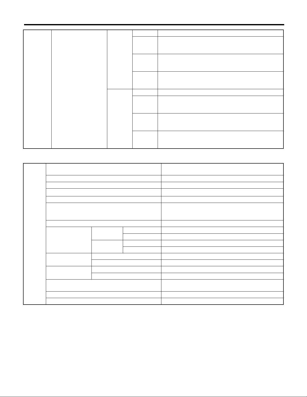
1. DOHC TURBO MODEL (EXCEPT FOR STi AND AUSTRALIA MODEL)
Horizontally opposed, liquid cooled, 4-cylinder,
4-stroke gasoline engine
1,994 (121.67)
981 — 1,177 (10 — 12, 142 — 171)
700±100 (No load)
800±150 (A/C switch ON)
Engine
Type
Valve arrangement Belt driven, double overhead camshaft, 4-valve/cylinder
Bore × Stroke mm (in) 92 × 75 (3.62 × 2.95)
Piston displacement
Compression ratio 8.0
Compression pres-
sure (at 200 — 300
rpm)
Number of piston rings Pressure ring: 2, Oil ring: 1
Intake valve timing
Exhaust valve timing
Valve clearance
Idling speed
[At neutral position on MT or “P” or
“N” range on AT]
Firing order 1 → 3 → 2 → 4
Ignition timing BTDC/rpm 12°±10°/700
Opening BTDC 10°
Closing ABDC 50°
Opening BBDC 53°
Closing ATDC 7°
Intake mm (in) 0.20±0.02 (0.0079±0.0008)
Exhaust mm (in) 0.35±0.02 (0.0138±0.0008)
kPa (kgf/cm
cm
3
(cu in)
2
, psi)
rpm
NOTE:
STD: Standard I.D.: Inner Diameter O.D.: Outer Diameter OS: Oversize US: Undersize
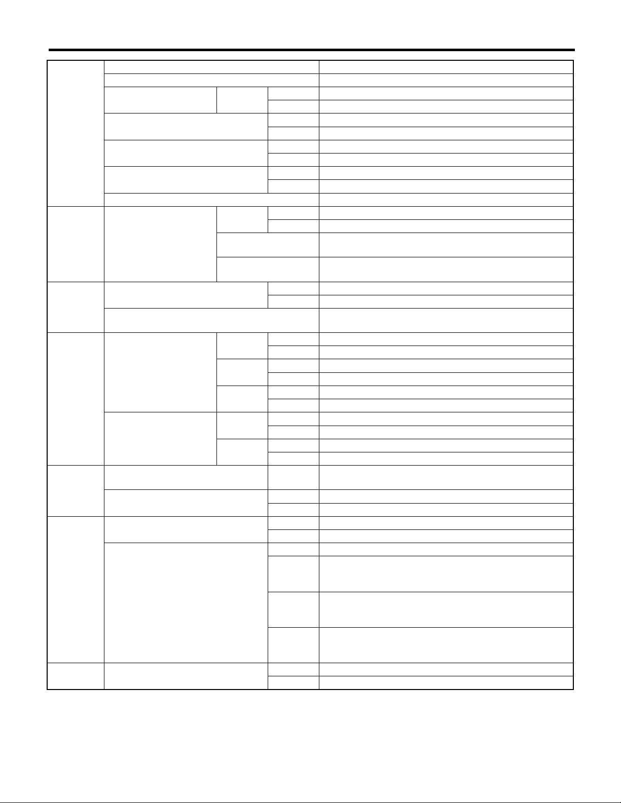
Belt
tension
adjuster
Belt
tensioner
Camshaft
Cylinder
head
Protrusion of adjuster rod 5.2 — 6.2 mm (0.205 — 0.244 in)
Spacer O.D. 17.955 — 17.975 mm (0.7069 — 0.7077 in)
Tensioner bush I.D. 18.0 — 18.08 mm (0.7087 — 0.7118 in)
Clearance between spacer and bush
Side clearance of spacer
Bend limit 0.020 mm (0.0079 in)
Thrust clearance
Intake
Cam lobe height
Exhaust
Journal O.D. STD
Oil clearance
Surface warpage limit 0.05 mm (0.0020 in)
Surface grinding limit 0.3 mm (0.012 in)
Standard height 127.5 mm (5.02 in)
STD 0.025 — 0.125 mm (0.0010 — 0.0049 in)
Limit 0.175 mm (0.0069 in)
STD 0.2 — 0.55 mm (0.0079 — 0.0217 in)
Limit 0.81 mm (0.0319 in)
STD 0.040 — 0.080 mm (0.0016 — 0.0031 in)
Limit 0.10 mm (0.0039 in)
STD 46.25 — 46.35 mm (1.821 — 1.825 in)
Limit 46.15 mm (1.817 in)
STD 46.15 — 46.25 mm (1.817 — 1.821 in)
Limit 46.05 mm (1.813 in)
Front 37.946 — 37.963 mm (1.4939 — 1.4946 in)
Center
rear
STD 0.037 — 0.072 mm (0.0015 — 0.0028 in)
Limit 0.10 mm (0.0039 in)
29.946 — 29.963 mm (1.1790 — 1.1796 in)
ME(H4DOTC)-2
Refacing angle 90°
Valve seat
Valve guide
Valve
Valve
spring
Cylinder
block
Piston Outer diameter
Piston pin
Contacting width
Inner diameter 6.000 — 6.012 mm (0.2362 — 0.2367 in)
Protrusion above head 15.8 — 16.2 mm (0.622 — 0.638 in)
Head edge thickness
Stem diameter
Stem oil clearance
Overall length
Free length 47.32 mm (1.8630 in)
Squareness 2.5°, 2.1 mm (0.083 in)
Tension/spring height
Surface warpage limit (mating with cylinder head) 0.05 mm (0.0020 in)
Surface grinding limit 0.1 mm (0.004 in)
Cylinder bore STD
Taper
Out-of-roundness
Piston clearance
Enlarging (boring) limit 0.5 mm (0.020 in)
Standard clearance between piston
pin and hole in piston
Degree of fit
General Description
Intake
Exhaust
Intake
Exhaust
STD
Limit — 0.15 mm (0.0059 in)
STD
0.25 mm (0.0098 in)
OS
0.50 mm (0.0197 in)
OS
STD 1.0 mm (0.039 in)
Limit 1.7 mm (0.067 in)
STD 1.5 mm (0.059 in)
Limit 2.2 mm (0.087 in)
STD 1.2 mm (0.047 in)
Limit 0.8 mm (0.031 in)
STD 1.5 mm (0.059 in)
Limit 0.8 mm (0.031 in)
Intake 5.955 — 5.970 mm (0.2344 — 0.2350 in)
Exhaust 5.945 — 5.960 mm (0.2341 — 0.2346 in)
Intake 0.030 — 0.057 mm (0.0012 — 0.0022 in)
Exhaust 0.040 — 0.067 mm (0.0016 — 0.0026 in)
Intake 104.4 mm (4.110 in)
Exhaust 104.7 mm (4.122 in)
Set
Lift
A 92.005 — 92.015 mm (3.6222 — 3.6226 in)
B 91.995 — 92.005 mm (3.6218 — 3.6222 in)
STD 0.015 mm (0.0006 in)
Limit 0.050 mm (0.0020 in)
STD 0.010 mm (0.0004 in)
Limit 0.050 mm (0.0020 in)
STD 0.010 — 0.030 mm (0.0004 — 0.0012 in)
Limit 0.050 mm (0.0020 in)
A 91.985 — 91.995 mm (3.6214 — 3.6218 in)
B 91.975 — 91.985 mm (3.6211 — 3.6214 in)
STD 0.004 — 0.008 mm (0.0002 — 0.0003 in)
Limit 0.020 mm (0.0008 in)
205 — 235 N (20.9 — 24.0 kgf, 46.1 — 52.8 lb)/
36.0 mm (1.417 in)
426 — 490 N (43.4 — 50.0 kgf, 95.8 — 110 lb)/
26.5 mm (1.043 in)
92.225 — 92.235 mm (3.6309 — 3.6313 in)
92.475 — 92.485 mm (3.6407 — 3.6411 in)
Piston pin must be fitted into position with thumb at 20°C
(68°F).
MECHANICAL
ME(H4DOTC)-3
MECHANICAL
General Description
Piston ring
Connecting
rod
Connecting
rod bearing
Connecting
rod bushing
Top ring
Piston ring gap
Clearance between piston
ring and piston ring
groove
Bend or twist per 100 mm (3.94 in) in
length
Side clearance
Oil clearance
Thickness at center portion
Clearance between piston pin and
bushing
Second
ring
Oil ring
Top ring
Second
ring
STD 0.20 — 0.25 mm (0.0079 — 0.0098 in)
Limit 1.0 mm (0.039 in)
STD 0.40 — 0.50 mm (0.016 — 0.020 in)
Limit 1.0 mm (0.039 in)
STD 0.20 — 0.50 mm (0.0079 — 0.020 in)
Limit 1.5 mm (0.059 in)
STD 0.04 — 0.08 mm (0.0016 — 0.0031 in)
Limit 0.15 mm (0.0059 in)
STD 0.030 — 0.070 mm (0.0012 — 0.0028 in)
Limit 0.15 mm (0.0059 in)
Limit 0.10 mm (0.0039 in)
STD 0.070 — 0.330 mm (0.0028 — 0.0130 in)
Limit 0.4 mm (0.016 in)
STD 0.020 — 0.046 mm (0.0008 — 0.0018 in)
Limit 0.05 mm (0.0020 in)
STD 1.486 — 1.498 mm (0.0585 — 0.0590 in)
0.03 mm
(0.0012
in) US
0.05 mm
(0.0020
in) US
0.25 mm
(0.0098
in) US
STD 0 — 0.022 mm (0 — 0.0009 in)
Limit 0.030 mm (0.0012 in)
1.504 — 1.512 mm (0.0592 — 0.0595 in)
1.514 — 1.522 mm (0.0596 — 0.0599 in)
1.614 — 1.622 mm (0.0635 — 0.0639 in)
ME(H4DOTC)-4

Crankshaft
General Description
Bend limit 0.035 mm (0.0014 in)
Crank pin and crank journal
Crank pin outer diameter
Crank journal outer diameter
Thrust clearance
Oil clearance
Out-of-roundness 0.005 mm (0.0002 in) or less
Grinding limit 0.25 mm (0.0098 in)
STD 51.984 — 52.000 mm (2.0466 — 2.0472 in)
0.03 mm
#1, #3, #5
#2, #4
#1
#2
#3
#4
#5
(0.0012
in) US
0.05 mm
(0.0020
in) US
0.25 mm
(0.0098
in) US
STD 59.992 — 60.008 mm (2.3619 — 2.3625 in)
0.03 mm
(0.0012
in) US
0.05 mm
(0.0020
in) US
0.25 mm
(0.0098
in) US
STD 59.992 — 60.008 mm (2.3619 — 2.3625 in)
0.03 mm
(0.0012
in) US
0.05 mm
(0.0020
in) US
0.25 mm
(0.0098
in) US
STD 0.030 — 0.115 mm (0.0012 — 0.0045 in)
Limit 0.25 mm (0.0098 in)
STD 0.010 — 0.030 mm (0.0004 — 0.0012 in)
Limit 0.040 mm (0.0016 in)
STD 0.010 — 0.030 mm (0.0004 — 0.0012 in)
Limit 0.045 mm (0.0018 in)
STD 0.010 — 0.030 mm (0.0004 — 0.0012 in)
Limit 0.040 mm (0.0016 in)
STD 0.010 — 0.030 mm (0.0004 — 0.0012 in)
Limit 0.045 mm (0.0018 in)
STD 0.010 — 0.030 mm (0.0004 — 0.0012 in)
Limit 0.040 mm (0.0016 in)
51.954 — 51.970 mm (2.0454 — 2.0461 in)
51.934 — 51.950 mm (2.0447 — 2.0453 in)
51.734 — 51.750 mm (2.0368 — 2.0374 in)
59.962 — 59.978 mm (2.3607 — 2.3613 in)
59.942 — 59.958 mm (2.3599 — 2.3605 in)
59.742 — 59.758 mm (2.3520 — 2.3527 in)
59.962 — 59.978 mm (2.3607 — 2.3613 in)
59.942 — 59.958 mm (2.3599 — 2.3605 in)
59.742 — 59.758 mm (2.3520 — 2.3527 in)
MECHANICAL
ME(H4DOTC)-5
MECHANICAL
Crankshaft
bearing
Crankshaft bearing thickness
2. STi MODEL
General Description
STD 1.998 — 2.011 mm (0.0787 — 0.0792 in)
0.03 mm
(0.0012
in) US
#1, #3
#2, #4, #5
0.05 mm
(0.0020
in) US
0.25 mm
(0.0098
in) US
STD 2.000 — 2.013 mm (0.0787 — 0.0793 in)
0.03 mm
(0.0012
in) US
0.05 mm
(0.0020
in) US
0.25 mm
(0.0098
in) US
2.017 — 2.020 mm (0.0794 — 0.0795 in)
2.027 — 2.030 mm (0.0798 — 0.0799 in)
2.127 — 2.130 mm (0.0837 — 0.0839 in)
2.019 — 2.022 mm (0.0795 — 0.0796 in)
2.029 — 2.032 mm (0.0799 — 0.0800 in)
2.129 — 2.132 mm (0.0838 — 0.0839 in)
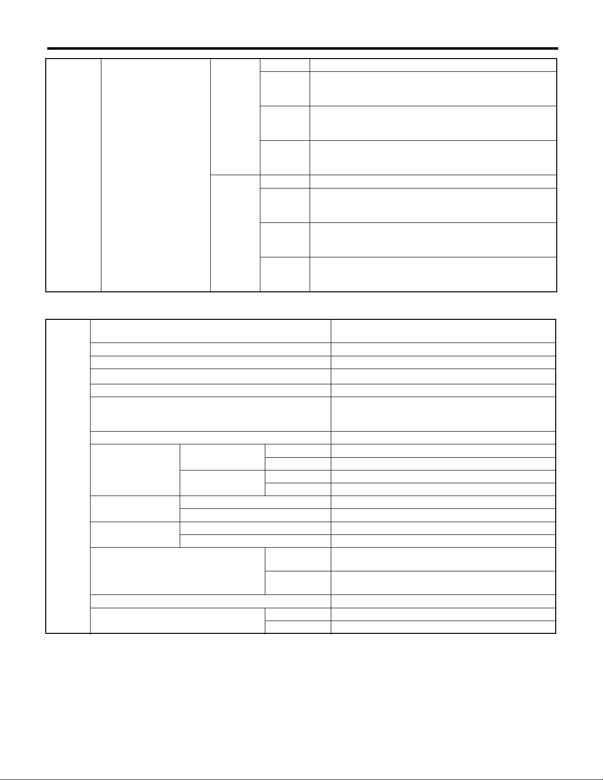
Engine
Type
Valve arrangement Belt driven, double overhead camshaft, 4-valve/cylinder
Bore × Stroke mm (in) 92 × 75 (3.62 × 2.95)
Piston displacement
Compression ratio 8.0
Compression pres-
sure (at 200 — 300
rpm)
Number of piston rings Pressure ring: 2, Oil ring: 1
Opening
Intake valve timing
Closing
Exhaust valve timing
Valve clearance
Idling speed
[At neutral position on MT]
Firing order 1 → 3 → 2 → 4
Ignition timing BTDC/rpm 12°±10°/700
Opening BBDC 58°
Closing ATDC 10°
Intake mm (in) 0.20±0.02 (0.0079±0.0008)
Exhaust mm (in) 0.35±0.02 (0.0138±0.0008)
kPa (kgf/cm
Max. retard ATDC 6°
Min. advance BTDC 24°
Max. retard ABDC 68°
Min. advance ABDC 38°
cm
3
(cu in)
2
, psi)
rpm
Horizontally opposed, liquid cooled, 4-cylinder,
4-stroke gasoline engine
1,994 (121.67)
981 — 1,177 (10 — 12, 142 — 171)
700±100 (No load)
800±150 (A/C switch ON)
NOTE:
STD: Standard I.D.: Inner Diameter O.D.: Outer Diameter OS: Oversize US: Undersize
ME(H4DOTC)-6

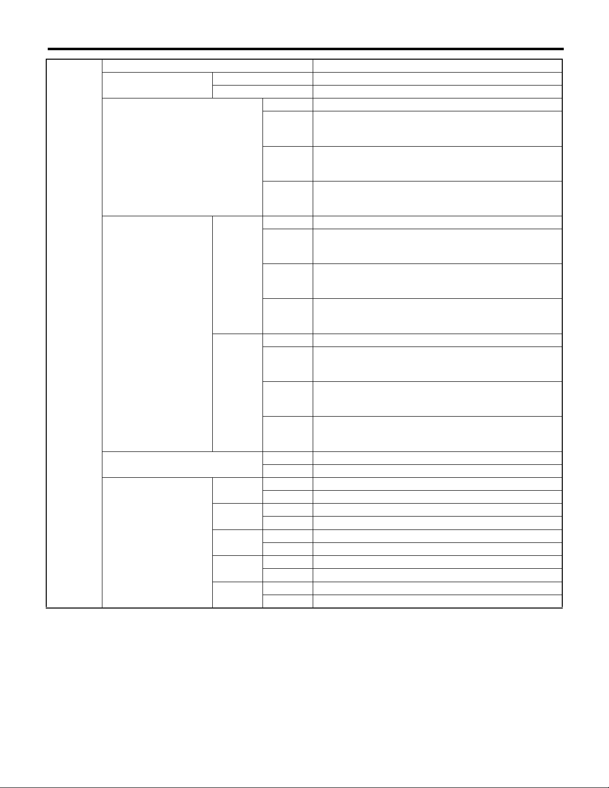
Belt
tension
adjuster
Belt
tensioner
Camshaft
Cylinder
head
Valve seat
Valve guide
Valve
Valve
spring
General Description
MECHANICAL
Protrusion of adjuster rod 5.2 — 6.2 mm (0.205 — 0.244 in)
Spacer O.D. 17.955 — 17.975 mm (0.7069 — 0.7077 in)
Tensioner bush I.D. 18.0 — 18.08 mm (0.7087 — 0.7118 in)
Clearance between spacer and bush
Side clearance of spacer
Bend limit 0.020 mm (0.0079 in)
Thrust clearance
Intake
Cam lobe height
Exhaust
Journal O.D. STD
Oil clearance
Surface warpage limit 0.05 mm (0.0020 in)
Surface grinding limit 0.3 mm (0.012 in)
Standard height 127.5 mm (5.02 in)
Refacing angle 90°
Intake
Contacting width
Exhaust
Inner diameter 6.000 — 6.012 mm (0.2362 — 0.2367 in)
Protrusion above head 15.8 — 16.2 mm (0.622 — 0.638 in)
Intake
Head edge thickness
Exhaust
Stem diameter
Stem oil clearance
Overall length
Free length 43.89 mm (1.728 in)
Squareness 2.5°, 1.9 mm (0.075 in)
Tension/spring height
STD
Limit — 0.15 mm (0.0059 in)
STD 0.025 — 0.125 mm (0.0010 — 0.0049 in)
Limit 0.175 mm (0.0069 in)
STD 0.2 — 0.55 mm (0.0079 — 0.0217 in)
Limit 0.81 mm (0.0319 in)
STD 0.040 — 0.080 mm (0.0016 — 0.0031 in)
Limit 0.10 mm (0.0039 in)
STD 45.25 — 45.35 mm (1.781 — 1.785 in)
Limit 45.15 mm (1.758 in)
STD 45.60 — 45.70 mm (1.795 — 1.799 in)
Limit 45.50 mm (1.791 in)
Front 37.946 — 37.963 mm (1.4939 — 1.4946 in)
Center
rear
STD 0.037 — 0.072 mm (0.0015 — 0.0028 in)
Limit 0.10 mm (0.0039 in)
STD 1.0 mm (0.039 in)
Limit 1.7 mm (0.067 in)
STD 1.5 mm (0.059 in)
Limit 2.2 mm (0.087 in)
STD 1.2 mm (0.047 in)
Limit 0.8 mm (0.031 in)
STD 1.5 mm (0.059 in)
Limit 0.8 mm (0.031 in)
Intake 5.955 — 5.970 mm (0.2344 — 0.2350 in)
Exhaust 5.945 — 5.960 mm (0.2341 — 0.2346 in)
Intake 0.030 — 0.057 mm (0.0012 — 0.0022 in)
Exhaust 0.040 — 0.067 mm (0.0016 — 0.0026 in)
Intake 104.4 mm (4.110 in)
Exhaust 104.7 mm (4.122 in)
Set
Lift
29.946 — 29.963 mm (1.1790 — 1.1796 in)
205 — 237 N (20.9 — 24.2 kgf, 46.1 — 53.3 lb)/
36.0 mm (1.417 in)
553 — 611 N (56.4 — 62.3 kgf, 124 — 137 lb)/
26.45 mm (1.041 in)
ME(H4DOTC)-7
MECHANICAL
Surface warpage limit (mating with cylinder head) 0.05 mm (0.0020 in)
Surface grinding limit 0.1 mm (0.004 in)
Cylinder bore STD
Cylinder
block
Piston Outer diameter
Piston pin
Piston ring
Connecting
rod
Connecting
rod bearing
Connecting
rod bushing
Taper
Out-of-roundness
Piston clearance
Enlarging (boring) limit 0.5 mm (0.020 in)
Standard clearance between piston
pin and hole in piston
Degree of fit
Piston ring gap
Clearance between piston
ring and piston ring
groove
Bend or twist per 100 mm (3.94 in) in
length
Side clearance
Oil clearance
Thickness at center portion
Clearance between piston pin and
bushing
General Description
A 92.005 — 92.015 mm (3.6222 — 3.6226 in)
B 91.995 — 92.005 mm (3.6218 — 3.6222 in)
STD 0.015 mm (0.0006 in)
Limit 0.050 mm (0.0020 in)
STD 0.010 mm (0.0004 in)
Limit 0.050 mm (0.0020 in)
STD 0.010 — 0.030 mm (0.0004 — 0.0012 in)
Limit 0.050 mm (0.0020 in)
STD
0.25 mm (0.0098 in)
OS
0.50 mm (0.0197 in)
OS
Top ring
Second
ring
Oil ring
Top ring
Second
ring
A 91.985 — 91.995 mm (3.6214 — 3.6218 in)
B 91.975 — 91.985 mm (3.6211 — 3.6214 in)
STD 0.004 — 0.008 mm (0.0002 — 0.0003 in)
Limit 0.020 mm (0.0008 in)
STD 0.20 — 0.25 mm (0.0079 — 0.0098 in)
Limit 1.0 mm (0.039 in)
STD 0.40 — 0.50 mm (0.016 — 0.020 in)
Limit 1.0 mm (0.039 in)
STD 0.20 — 0.50 mm (0.0079 — 0.020 in)
Limit 1.5 mm (0.059 in)
STD 0.040 — 0.080 mm (0.0016 — 0.0031 in)
Limit 0.15 mm (0.0059 in)
STD 0.030 — 0.070 mm (0.0012 — 0.0028 in)
Limit 0.15 mm (0.0059 in)
Limit 0.10 mm (0.0039 in)
STD 0.070 — 0.330 mm (0.0028 — 0.0130 in)
Limit 0.4 mm (0.016 in)
STD 0.020 — 0.046 mm (0.0008 — 0.0018 in)
Limit 0.05 mm (0.0020 in)
STD 1.486 — 1.498 mm (0.0585 — 0.0590 in)
0.03 mm
(0.0012
in) US
0.05 mm
(0.0020
in) US
0.25 mm
(0.0098
in) US
STD 0 — 0.022 mm (0 — 0.0009 in)
Limit 0.030 mm (0.0012 in)
92.225 — 92.235 mm (3.6309 — 3.6313 in)
92.475 — 92.485 mm (3.6407 — 3.6411 in)
Piston pin must be fitted into position with thumb at 20°C
(68°F).
1.504 — 1.512 mm (0.0592 — 0.0595 in)
1.514 — 1.522 mm (0.0596 — 0.0599 in)
1.614 — 1.622 mm (0.0635 — 0.0639 in)
ME(H4DOTC)-8

Crankshaft
General Description
Bend limit 0.035 mm (0.0014 in)
Crank pin and crank journal
Crank pin outer diameter
Crank journal outer diameter
Thrust clearance
Oil clearance
Out-of-roundness 0.005 mm (0.0002 in) or less
Grinding limit 0.25 mm (0.0098 in)
STD 51.984 — 52.000 mm (2.0466 — 2.0472 in)
0.03 mm
#1, #3, #5
#2, #4
#1
#2
#3
#4
#5
(0.0012
in) US
0.05 mm
(0.0020
in) US
0.25 mm
(0.0098
in) US
STD 59.992 — 60.008 mm (2.3619 — 2.3625 in)
0.03 mm
(0.0012
in) US
0.05 mm
(0.0020
in) US
0.25 mm
(0.0098
in) US
STD 59.992 — 60.008 mm (2.3619 — 2.3625 in)
0.03 mm
(0.0012
in) US
0.05 mm
(0.0020
in) US
0.25 mm
(0.0098
in) US
STD 0.030 — 0.115 mm (0.0012 — 0.0045 in)
Limit 0.25 mm (0.0098 in)
STD 0.010 — 0.030 mm (0.0004 — 0.0012 in)
Limit 0.040 mm (0.0016 in)
STD 0.010 — 0.030 mm (0.0004 — 0.0012 in)
Limit 0.045 mm (0.0018 in)
STD 0.010 — 0.030 mm (0.0004 — 0.0012 in)
Limit 0.040 mm (0.0016 in)
STD 0.010 — 0.030 mm (0.0004 — 0.0012 in)
Limit 0.045 mm (0.0018 in)
STD 0.010 — 0.030 mm (0.0004 — 0.0012 in)
Limit 0.040 mm (0.0016 in)
51.954 — 51.970 mm (2.0454 — 2.0461 in)
51.934 — 51.950 mm (2.0447 — 2.0453 in)
51.734 — 51.750 mm (2.0368 — 2.0374 in)
59.962 — 59.978 mm (2.3607 — 2.3613 in)
59.942 — 59.958 mm (2.3599 — 2.3605 in)
59.742 — 59.758 mm (2.3520 — 2.3527 in)
59.962 — 59.978 mm (2.3607 — 2.3613 in)
59.942 — 59.958 mm (2.3599 — 2.3605 in)
59.742 — 59.758 mm (2.3520 — 2.3527 in)
MECHANICAL
ME(H4DOTC)-9
General Description
MECHANICAL
STD 1.998 — 2.011 mm (0.0787 — 0.0792 in)
0.03 mm
(0.0012
in) US
0.05 mm
(0.0020
in) US
0.25 mm
(0.0098
in) US
STD 2.000 — 2.013 mm (0.0787 — 0.0793 in)
0.03 mm
(0.0012
in) US
0.05 mm
(0.0020
in) US
0.25 mm
(0.0098
in) US
Crankshaft
bearing
#1, #3
Crankshaft bearing thickness
#2, #4, #5
3. DOHC TURBO MODEL (AUSTRALIA MODEL EXCEPT FOR STi MODEL)
2.017 — 2.020 mm (0.0794 — 0.0795 in)
2.027 — 2.030 mm (0.0798 — 0.0799 in)
2.127 — 2.130 mm (0.0837 — 0.0839 in)
2.019 — 2.022 mm (0.0795 — 0.0796 in)
2.029 — 2.032 mm (0.0799 — 0.0800 in)
2.129 — 2.132 mm (0.0838 — 0.0839 in)
Engine
Type
Valve arrangement Belt driven, double overhead camshaft, 4-valve/cylinder
Bore × Stroke mm (in) 92 × 75 (3.62 × 2.95)
Piston displacement
Compression ratio 9.0
Compression pres-
sure (at 200 — 300
rpm)
Number of piston rings Pressure ring: 2, Oil ring: 1
Opening
Intake valve timing
Closing
Exhaust valve timing
Valve clearance
Idling speed
[At neutral position on MT, or
“P” or “N” position on AT]
Firing order 1 → 3 → 2 → 4
Ignition timing BTDC/rpm
Opening BBDC 53°
Closing ATDC 7°
Intake mm (in) 0.20±0.02 (0.0079±0.0008)
Exhaust mm (in) 0.35±0.02 (0.0138±0.0008)
kPa (kgf/cm
rpm
3
(cu in)
cm
2
, psi)
Max. retard ATDC 7°
Min. advance BTDC 27°
Max. retard ABDC 67°
Min. advance ABDC 33°
MT
AT
MT 12°±3°/650
AT 12°±3°/700
Horizontally opposed, liquid cooled, 4-cylinder,
4-stroke gasoline engine
1,994 (121.67)
1,108 — 1,304 (11 — 13, 161 — 189)
650±50 (No load)
800±50 (A/C switch ON)
700±50 (No load)
820±50 (A/C switch ON)
NOTE:
STD: Standard I.D.: Inner Diameter O.D.: Outer Diameter OS: Oversize US: Undersize
ME(H4DOTC)-10

Belt
tension
adjuster
Belt
tensioner
Camshaft
Cylinder
head
Valve seat
Valve guide
Valve
Valve
spring
General Description
MECHANICAL
Protrusion of adjuster rod 5.2 — 6.2 mm (0.205 — 0.244 in)
Spacer O.D. 17.955 — 17.975 mm (0.7069 — 0.7077 in)
Tensioner bush I.D. 18.0 — 18.08 mm (0.7087 — 0.7118 in)
Clearance between spacer and bush
Side clearance of spacer
Bend limit 0.020 mm (0.0079 in)
Thrust clearance
Intake
Cam lobe height
Exhaust
Journal O.D. STD
Oil clearance
Surface warpage limit 0.05 mm (0.0020 in)
Surface grinding limit 0.3 mm (0.012 in)
Standard height 127.5 mm (5.02 in)
Refacing angle 90°
Intake
Contacting width
Exhaust
Inner diameter 6.000 — 6.012 mm (0.2362 — 0.2367 in)
Protrusion above head 15.8 — 16.2 mm (0.622 — 0.638 in)
Intake
Head edge thickness
Exhaust
Stem diameter
Stem oil clearance
Overall length
Free length 47.32 mm (1.8630 in)
Squareness 2.5°, 2.1 mm (0.083 in)
Tension/spring height
STD
Limit — 0.15 mm (0.0059 in)
STD 0.025 — 0.125 mm (0.0010 — 0.0049 in)
Limit 0.175 mm (0.0069 in)
STD 0.2 — 0.55 mm (0.0079 — 0.0217 in)
Limit 0.81 mm (0.0319 in)
STD 0.040 — 0.080 mm (0.0016 — 0.0031 in)
Limit 0.10 mm (0.0039 in)
STD 46.25 — 46.35 mm (1.821 — 1.825 in)
Limit 46.15 mm (1.817 in)
STD 46.15 — 46.25 mm (1.817 — 1.821 in)
Limit 46.05 mm (1.813 in)
Front 37.946 — 37.963 mm (1.4939 — 1.4946 in)
Center
rear
STD 0.037 — 0.072 mm (0.0015 — 0.0028 in)
Limit 0.10 mm (0.0039 in)
STD 1.0 mm (0.039 in)
Limit 1.7 mm (0.067 in)
STD 1.5 mm (0.059 in)
Limit 2.2 mm (0.087 in)
STD 1.2 mm (0.047 in)
Limit 0.8 mm (0.031 in)
STD 1.5 mm (0.059 in)
Limit 0.8 mm (0.031 in)
Intake 5.955 — 5.970 mm (0.2344 — 0.2350 in)
Exhaust 5.945 — 5.960 mm (0.2341 — 0.2346 in)
Intake 0.030 — 0.057 mm (0.0012 — 0.0022 in)
Exhaust 0.040 — 0.067 mm (0.0016 — 0.0026 in)
Intake 104.4 mm (4.110 in)
Exhaust 104.7 mm (4.122 in)
Set
Lift
29.946 — 29.963 mm (1.1790 — 1.1796 in)
205 — 235 N (20.9 — 24.0 kgf, 46.1 — 52.8 lb)/
36.0 mm (1.417 in)
426 — 490 N (43.4 — 50.0 kgf, 95.8 — 110 lb)/
26.5 mm (1.043 in)
ME(H4DOTC)-11

MECHANICAL
Surface warpage limit (mating with cylinder head) 0.05 mm (0.0020 in)
Surface grinding limit 0.1 mm (0.004 in)
Cylinder bore STD
Cylinder
block
Piston Outer diameter
Piston pin
Piston ring
Connecting
rod
Connecting
rod bearing
Connecting
rod bushing
Taper
Out-of-roundness
Piston clearance
Enlarging (boring) limit 0.5 mm (0.020 in)
Standard clearance between piston
pin and hole in piston
Degree of fit
Piston ring gap
Clearance between piston
ring and piston ring
groove
Bend or twist per 100 mm (3.94 in) in
length
Side clearance
Oil clearance
Thickness at center portion
Clearance between piston pin and
bushing
General Description
A 92.005 — 92.015 mm (3.6222 — 3.6226 in)
B 91.995 — 92.005 mm (3.6218 — 3.6222 in)
STD 0.015 mm (0.0006 in)
Limit 0.050 mm (0.0020 in)
STD 0.010 mm (0.0004 in)
Limit 0.050 mm (0.0020 in)
STD 0.010 — 0.030 mm (0.0004 — 0.0012 in)
Limit 0.050 mm (0.0020 in)
STD
0.25 mm (0.0098 in)
OS
0.50 mm (0.0197 in)
OS
Top ring
Second
ring
Oil ring
Top ring
Second
ring
A 91.985 — 91.995 mm (3.6214 — 3.6218 in)
B 91.975 — 91.985 mm (3.6211 — 3.6214 in)
STD 0.004 — 0.008 mm (0.0002 — 0.0003 in)
Limit 0.020 mm (0.0008 in)
STD 0.20 — 0.25 mm (0.0079 — 0.0098 in)
Limit 1.0 mm (0.039 in)
STD 0.40 — 0.50 mm (0.016 — 0.020 in)
Limit 1.0 mm (0.039 in)
STD 0.20 — 0.50 mm (0.0079 — 0.020 in)
Limit 1.5 mm (0.059 in)
STD 0.040 — 0.080 mm (0.0016 — 0.0031 in)
Limit 0.15 mm (0.0059 in)
STD 0.030 — 0.070 mm (0.0012 — 0.0028 in)
Limit 0.15 mm (0.0059 in)
Limit 0.10 mm (0.0039 in)
STD 0.070 — 0.330 mm (0.0028 — 0.0130 in)
Limit 0.4 mm (0.016 in)
STD 0.020 — 0.046 mm (0.0008 — 0.0018 in)
Limit 0.05 mm (0.0020 in)
STD 1.486 — 1.498 mm (0.0585 — 0.0590 in)
0.03 mm
(0.0012
in) US
0.05 mm
(0.0020
in) US
0.25 mm
(0.0098
in) US
STD 0 — 0.022 mm (0 — 0.0009 in)
Limit 0.030 mm (0.0012 in)
92.225 — 92.235 mm (3.6309 — 3.6313 in)
92.475 — 92.485 mm (3.6407 — 3.6411 in)
Piston pin must be fitted into position with thumb at 20°C
(68°F).
1.504 — 1.512 mm (0.0592 — 0.0595 in)
1.514 — 1.522 mm (0.0596 — 0.0599 in)
1.614 — 1.622 mm (0.0635 — 0.0639 in)
ME(H4DOTC)-12
Crankshaft
General Description
Bend limit 0.035 mm (0.0014 in)
Crank pin and crank journal
Crank pin outer diameter
Crank journal outer diameter
Thrust clearance
Oil clearance
Out-of-roundness 0.005 mm (0.0002 in) or less
Grinding limit 0.25 mm (0.0098 in)
STD 51.984 — 52.000 mm (2.0466 — 2.0472 in)
0.03 mm
#1, #3, #5
#2, #4
#1
#2
#3
#4
#5
(0.0012
in) US
0.05 mm
(0.0020
in) US
0.25 mm
(0.0098
in) US
STD 59.992 — 60.008 mm (2.3619 — 2.3625 in)
0.03 mm
(0.0012
in) US
0.05 mm
(0.0020
in) US
0.25 mm
(0.0098
in) US
STD 59.992 — 60.008 mm (2.3619 — 2.3625 in)
0.03 mm
(0.0012
in) US
0.05 mm
(0.0020
in) US
0.25 mm
(0.0098
in) US
STD 0.030 — 0.115 mm (0.0012 — 0.0045 in)
Limit 0.25 mm (0.0098 in)
STD 0.010 — 0.030 mm (0.0004 — 0.0012 in)
Limit 0.040 mm (0.0016 in)
STD 0.010 — 0.030 mm (0.0004 — 0.0012 in)
Limit 0.045 mm (0.0018 in)
STD 0.010 — 0.030 mm (0.0004 — 0.0012 in)
Limit 0.040 mm (0.0016 in)
STD 0.010 — 0.030 mm (0.0004 — 0.0012 in)
Limit 0.045 mm (0.0018 in)
STD 0.010 — 0.030 mm (0.0004 — 0.0012 in)
Limit 0.040 mm (0.0016 in)
51.954 — 51.970 mm (2.0454 — 2.0461 in)
51.934 — 51.950 mm (2.0447 — 2.0453 in)
51.734 — 51.750 mm (2.0368 — 2.0374 in)
59.962 — 59.978 mm (2.3607 — 2.3613 in)
59.942 — 59.958 mm (2.3599 — 2.3605 in)
59.742 — 59.758 mm (2.3520 — 2.3527 in)
59.962 — 59.978 mm (2.3607 — 2.3613 in)
59.942 — 59.958 mm (2.3599 — 2.3605 in)
59.742 — 59.758 mm (2.3520 — 2.3527 in)
MECHANICAL
ME(H4DOTC)-13
MECHANICAL
Crankshaft
bearing
Crankshaft bearing thickness
General Description
STD 1.998 — 2.011 mm (0.0787 — 0.0792 in)
0.03 mm
(0.0012
in) US
#1, #3
#2, #4, #5
0.05 mm
(0.0020
in) US
0.25 mm
(0.0098
in) US
STD 2.000 — 2.013 mm (0.0787 — 0.0793 in)
0.03 mm
(0.0012
in) US
0.05 mm
(0.0020
in) US
0.25 mm
(0.0098
in) US
2.017 — 2.020 mm (0.0794 — 0.0795 in)
2.027 — 2.030 mm (0.0798 — 0.0799 in)
2.127 — 2.130 mm (0.0837 — 0.0839 in)
2.019 — 2.022 mm (0.0795 — 0.0796 in)
2.029 — 2.032 mm (0.0799 — 0.0800 in)
2.129 — 2.132 mm (0.0838 — 0.0839 in)
ME(H4DOTC)-14
General Description
B: COMPONENT
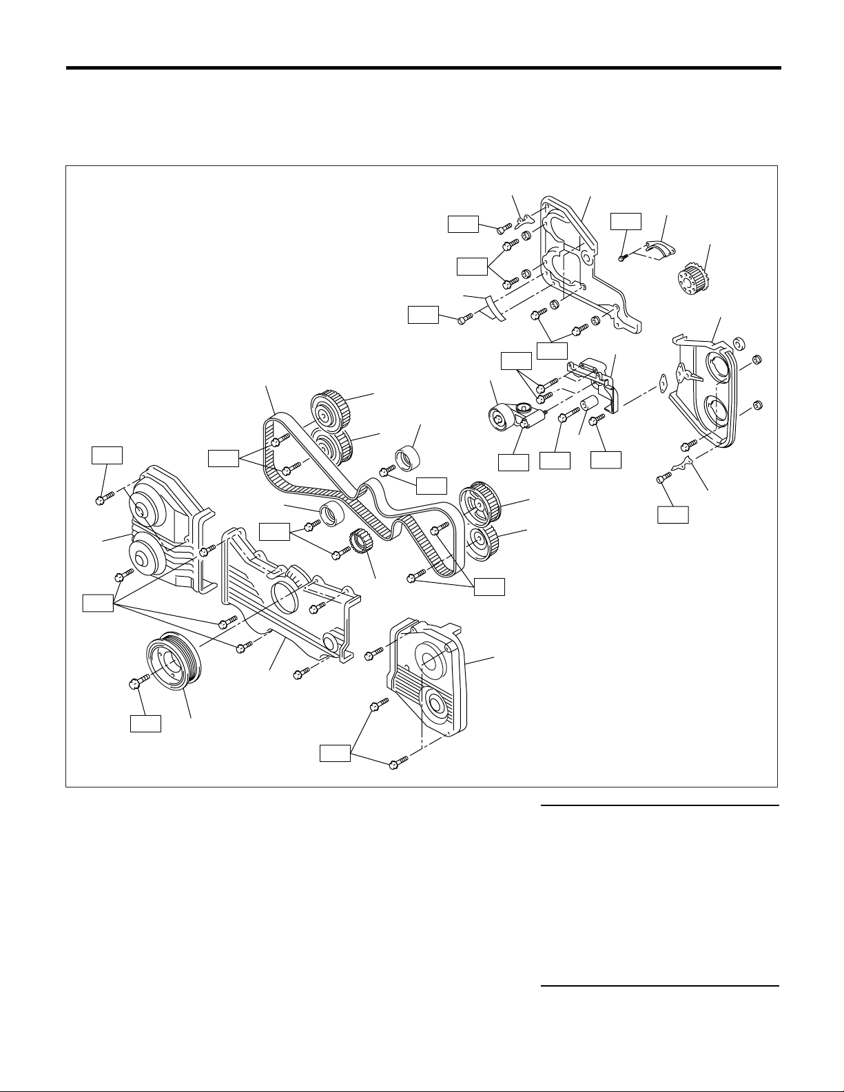
1. TIMING BELT
• EXCEPT FOR STi AND AUSTRALIA MODEL
MECHANICAL
(17)
T1
T1
T5
(12)
(14)
T4
(13)
(9)
(8)
T2
(7)
T4
(2)
T2
T1
(6)
T5
(2)
T4
T3
(10)
(11)
T1
T4
(1)
(2)
T7
(3)
(4)
(5)
(14)
T1
(2)
T2
(15)
(16)
T6
(18)
T1
ME-00601
(1) Timing belt cover No. 2 (RH) (10) Intake camshaft sprocket (LH) Tightening torque: N·m (kgf-m, ft-lb)
(2) Timing belt guide (MT model) (11) Exhaust camshaft sprocket (LH) T1: 5 (0.5, 3.6)
(3) Crankshaft sprocket (12) Timing belt T2: 6.4 (0.65, 4.7)
(4) Timing belt cover No. 2 (LH) (13) Belt idler No. 2 T3: 25 (2.5, 18.1)
(5) Tensioner bracket (14) Belt idler T4: 39 (4.0, 28.9)
(6) Automatic belt tension adjuster
ASSY
(7) Belt idler (17) Timing belt cover (RH)
(8) Exhaust camshaft sprocket (RH) (18) Crankshaft pulley
(15) Timing belt cover (LH) T5: 98 (10, 72.4)
(16) Front belt cover T6: <Ref. to ME(H4DOTC)-56,
INSTALLATION, CRANKSHAFT
PULLEY.>
(9) Intake camshaft sprocket (RH) T7: 10 (1.0, 7.2)
ME(H4DOTC)-15
MECHANICAL
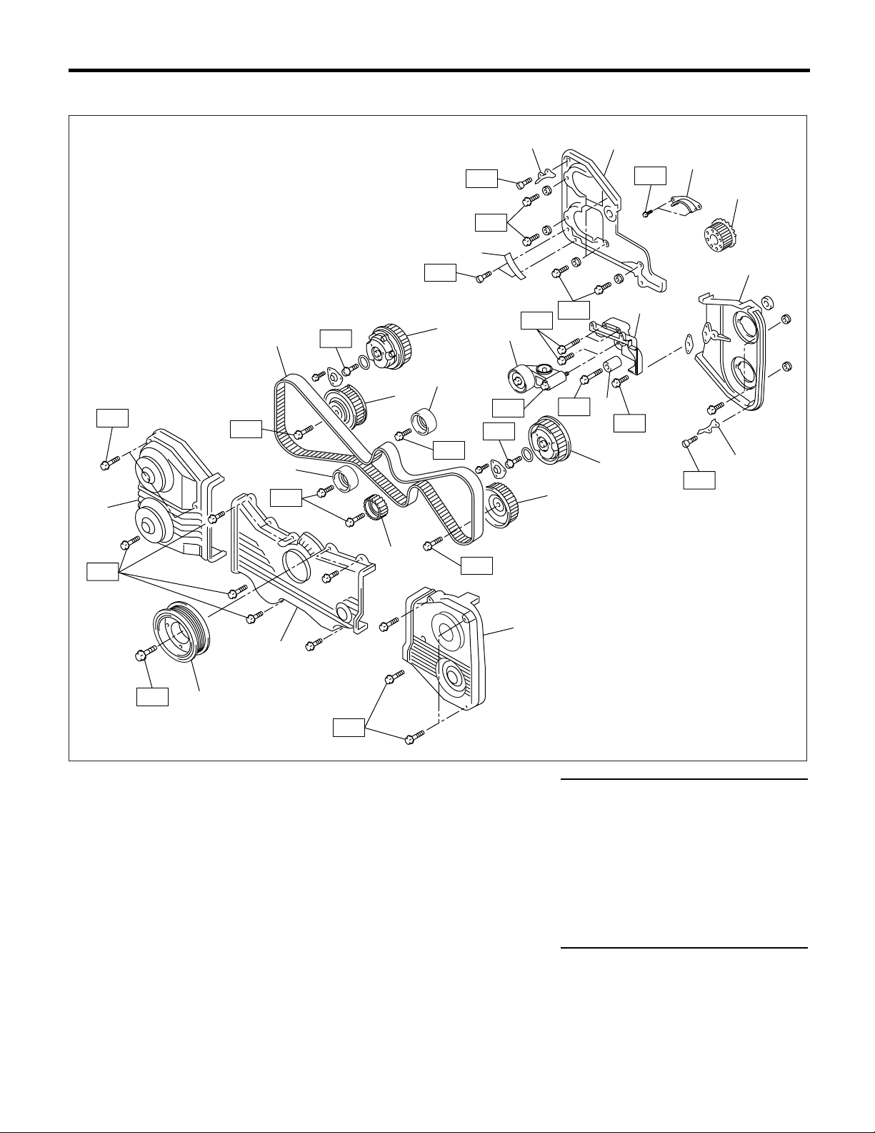
• STi AND AUSTRALIA MODEL
General Description
(17)
T1
T1
T5
(12)
(14)
T4
T5
(13)
(8)
(7)
T2
(9)
T4
(2)
T5
T2
T1
T5
(6)
T3
(2)
T3
(11)
T1
T4
(14)
(10)
(1)
(2)
T2
(3)
(4)
(5)
T1
(2)
T2
(15)
(16)
T6
(18)
T1
ME-00704
(1) Timing belt cover No. 2 (RH) (10) Intake camshaft sprocket (LH) Tightening torque: N·m (kgf-m, ft-lb)
(2) Timing belt guide (11) Exhaust camshaft sprocket (LH) T1: 5 (0.5, 3.6)
(3) Crankshaft sprocket (12) Timing belt T2: 6.4 (0.65, 4.7)
(4) Timing belt cover No. 2 (LH) (13) Belt idler No. 2 T3: 25 (2.5, 18.1)
(5) Tensioner bracket (14) Belt idler T4: 39 (4.0, 28.9)
(6) Automatic belt tension adjuster
ASSY
(7) Belt idler (17) Timing belt cover (RH)
(8) Exhaust camshaft sprocket (RH) (18) Crankshaft pulley
(15) Timing belt cover (LH) T5: 98 (10, 72.4)
(16) Front belt cover T6: <Ref. to ME(H4DOTC)-56,
INSTALLATION, CRANKSHAFT
PULLEY.>
(9) Intake camshaft sprocket (RH)
ME(H4DOTC)-16

General Description
2. CYLINDER HEAD AND CAMSHAFT
• EXCEPT FOR STi AND AUSTRALIA MODEL
T4
T2
(3)
(4)
(2)
MECHANICAL
(1)
T5
(5)
T5
(14)
T3
(32)
(9)
(18)
T3
(19)
(6)
(16)
(7)
(10)
(17)
(11)
(20)
(8)
(14)
(21)
T5
(12)
(32)
T1
(13)
(24)
T1
(13)
(22)
(25)
T3
T3
(31)
(15)
(16)
(28)
(29)
(30)
T4
T4
(3)
(4)
T2
(23)
T5
ME(H4DOTC)-17
(26)
(27)
T2
ME-00756

General Description
MECHANICAL
(1) Rocker cover (RH) (15) Cylinder head (RH) (29) Gasket
(2) Rocker cover gasket (RH) (16) Cylinder head gasket (30) Oil filler duct
(3) Oil separator cover (17) Cylinder head (LH) (31) O-ring
(4) Gasket (18) Intake camshaft (LH) (32) Stud bolt
(5) Intake camshaft cap (Front RH) (19) Exhaust camshaft (LH)
(6) Intake camshaft cap (Center RH) (20) Intake camshaft cap (Front LH) Tightening torque: N·m (kgf-m, ft-lb)
(7) Intake camshaft cap (Rear RH) (21) Intake camshaft cap (Center LH) T1: <Ref. to ME(H4DOTC)-78,
(8) Intake camshaft cap (RH) (22) Intake camshaft cap (Rear LH)
(9) Exhaust camshaft cap (Front RH) (23) Exhaust camshaft cap (Front LH)
(10) Exhaust camshaft cap (Center
RH)
(11) Exhaust camshaft cap (Rear RH) (25) Exhaust camshaft cap (Rear LH) T4: 6.4 (0.65, 4.7)
(12) Exhaust camshaft (RH) (26) Rocker cover gasket (LH) T5: 10 (1.0, 7.2)
(13) Cylinder head bolt (27) Rocker cover (LH)
(14) Oil seal (28) Oil filler cap
(24) Exhaust camshaft cap (Center
LH)
INSTALLATION, CYLINDER
HEAD ASSEMBLY.>
T2: 5 (0.5, 3.6)
T3: 20 (2.0, 14.5)
ME(H4DOTC)-18

• STi AND AUSTRALIA MODEL
T2
General Description
MECHANICAL
(2)
T5
(1)
T3
(3)
(7)
T3
(11)
(28)
(6)
(15)
(9)
(16)
(13)
(4)
T3
(14)
(17)
(8)
(5)
T5
(11)
(28)
(10)
T1
(10)
(18)
T5
(21)
(20)
(12)
(13)
(24)
(25)
(26)
T4
(27)
(22)
T2
T3
(19)
ME(H4DOTC)-19
T5
T2
(23)
ME-00705

General Description
MECHANICAL
(1) Rocker cover (RH) (13) Cylinder head gasket (25) Gasket
(2) Rocker cover gasket (RH) (14) Cylinder head (LH) (26) Oil filler duct
(3) Oil flow control solenoid valve
assembly (RH)
(4) Intake camshaft cap (RH) (17) Oil flow control solenoid valve
(5) Intake camshaft (RH) Tightening torque: N·m (kgf-m, ft-lb)
(6) Exhaust camshaft cap (Front RH) (18) Intake camshaft cap (LH) T1: <Ref. to ME(H4DOTC)-78,
(7) Exhaust camshaft cap (Center
RH)
(9) Exhaust camshaft (RH) (21) Exhaust camshaft cap (Rear LH) T3: 10 (1.0, 7)
(10) Cylinder head bolt (22) Rocker cover gasket (LH) T4: 6.4 (0.65, 4.7)
(11) Oil seal (23) Rocker cover (LH) T5: 20 (2.0, 14.5)
(12) Cylinder head (RH) (24) Oil filler cap
(15) Intake camshaft (LH) (27) O-ring
(16) Exhaust camshaft (LH) (28) Stud bolt
assembly (LH)
(19) Exhaust camshaft cap (Front LH)
(20) Exhaust camshaft cap (Center
LH)(8) Exhaust camshaft cap (Rear RH) T2: 5 (0.5, 3.6)
INSTALLATION, CYLINDER
HEAD ASSEMBLY.>
ME(H4DOTC)-20

General Description
3. CYLINDER HEAD AND VALVE ASSEMBLY
MECHANICAL
(1)
(2)
(12)
(4)
(3)
(10)
(6)
(11) (4) (5) (6) (7) (8) (9)
(4)
(12)
(11)
(4)
(5) (6)
(10)
(6)
(7)
(8)
(7)
(9)
(8)
(9)
(7)
(8)
(9)
(1) Exhaust valve (5) Intake valve oil seal (9) Valve lifter
(2) Intake valve (6) Valve spring (10) Exhaust valve oil seal
(3) Cylinder head (7) Retainer (11) Intake valve guide
(4) Valve spring seat (8) Retainer key (12) Exhaust valve guide
ME-00003
ME(H4DOTC)-21

MECHANICAL
4. CYLINDER BLOCK
General Description
(10)
(18)
(8)
T2
T2
(19)
(14)
T5
(7)
T2
T6
T2
(2)
(3)
(10)
(4)
T10
(27)
(16)
(10)
(15)
(1)
T8
T6
(3)
(10)
T6
(4)
(4)
(3)
(9)
(25)
T2
(5)
T2
(6)
T4
T2
(10)
(11)
T4
(12)
T2
T5
T2
(23)
T11
(24)
(17)
T7
(13)
(26)
ME-00725
T9
T1
T3
(21)
(22)
(20)
T1
(1) Oil pressure switch (16) Water by-pass pipe Tightening torque: N·m (kgf-m, ft-lb)
(2) Cylinder block (RH) (17) Connector T1: 5 (0.5, 3.6)
(3) Service hole plug (18) Oil strainer T2: 6.4 (0.65, 4.7)
(4) Gasket (19) Gasket T3: 10 (1.0, 7.2)
(5) Oil separator cover (20) Oil pan T4: 25 (2.5, 18.1)
(6) Water by-pass pipe (21) Drain plug T5: <Ref. to ME(H4DOTC)-89,
(7) Oil pump (22) Metal gasket
(8) Front oil seal (23) Oil level gauge guide
INSTALLATION, CYLINDER
BLOCK.>
(9) Rear oil seal (24) Oil filter T6: 69 (7.0, 50.6)
(10) O-ring (25) Gasket T7: First 12 (1.2, 8.7)
(11) Service hole cover (26) Water pump hose
Second 12 (1.2, 8.7)
(12) Cylinder block (LH) (27) Plug T8: 16 (1.6, 11.6)
(13) Water pump T9: 44 (4.5, 33)
(14) Baffle plate T10: 25 (2.5, 18.1)
(15) Oil cooler T11: 54 (5.5, 40)
ME(H4DOTC)-22

5. CRANKSHAFT AND PISTON
(1)
(2)
General Description
MECHANICAL
T2
(4)
(5)
(6)
(7)
(10)
(8)
(14)
(17)
(13)
(16)
(18)
(10)
(9)
(17)
(11)
(12)
(13)
(12)
(18)
(13)
(19)
(11)
(10)
(9)
(15)
(13)
(7)
(6)
T2
(3)
(14)
T1
(10)
(8)
(5)
ME-00005
(1) Flywheel (MT model) (10) Circlip (19) Crankshaft bearing #5
(2) Ball bearing (MT model) (11) Connecting rod bolt
(3) Reinforcement (AT model) (12) Connecting rod Tightening torque: N·m (kgf-m, ft-lb)
(4) Drive plate (AT model) (13) Connecting rod bearing T1: 45 (4.6, 33.3) (Except for STi
(5) Top ring (14) Connecting rod cap
model)
(6) Second ring (15) Crankshaft T1: 52 (5.3, 38.4) (STi model)
(7) Oil ring (16) Woodruff key T2: 72 (7.3, 52.8) (Except for STi
(8) Piston (17) Crankshaft bearing #1, #3
model)
(9) Piston pin (18) Crankshaft bearing #2, #4 T2: 77 (7.9, 56.8) (STi model)
ME(H4DOTC)-23

MECHANICAL
6. ENGINE MOUNTING
General Description
T2
(3)
T2
T1
(2)
(1)
T1
T3
(3)
(2)
T3
ME-00706
(1) Heat shield cover (3) Front engine mounting bracket Tightening torque: N·m (kgf-m, ft-lb)
(2) Front cushion rubber T1: 35 (3.6, 25.8)
T2: 42 (4.3, 30.9)
T3: 85 (8.7, 62.7)
ME(H4DOTC)-24

General Description
C: CAUTION
• Wear working clothing, including a cap, protective goggles, and protective shoes during operation.
• Remove contamination including dirt and corrosion before removal, installation or disassembly.
• Keep the disassembled parts in order and protect them from dust or dirt.
• Before removal, installation or disassembly, be
sure to clarify the failure. Avoid unnecessary removal, installation, disassembly, and replacement.
• Be careful not to burn your hands, because each
part in the vehicle is hot after running.
• Be sure to tighten fasteners including bolts and
nuts to the specified torque.
• Place shop jacks or safety stands at the specified
points.
• Before disconnecting electrical connectors of
sensors or units, be sure to disconnect the ground
cable from battery.
• All parts should be thoroughly cleaned, paying
special attention to the engine oil passages, pistons and bearings.
• Rotating parts and sliding parts such as piston,
bearing and gear should be coated with oil prior to
assembly.
• Be careful not to let oil, grease or coolant contact
the timing belt, clutch disc and flywheel.
• All removed parts, if to be reused, should be reinstalled in the original positions and directions.
• Bolts, nuts and washers should be replaced with
new ones as required.
• Even if necessary inspections have been made
in advance, proceed with assembly work while
making rechecks.
• Remove or install the engine in an area where
chain hoists, lifting devices, etc. are available for
ready use.
• Be sure not to damage coated surfaces of body
panels with tools or stain seats and windows with
coolant or oil. Place a cover over fenders, as required, for protection.
• Prior to starting work, prepare the following:
Service tools, clean cloth, containers to catch coolant and oil, wire ropes, chain hoist, transmission
jacks, etc.
• Lift-up or lower the vehicle when necessary.
Make sure to support the correct positions.
MECHANICAL
ME(H4DOTC)-25

MECHANICAL
D: PREPARATION TOOL
1. SPECIAL TOOLS
ILLUSTRATION TOOL NUMBER DESCRIPTION REMARKS
ST-498267600
General Description
498267600 CYLINDER
HEAD TABLE
498457000 ENGINE STAND
ADAPTER RH
• Used for replacing valve guides.
• Used for removing and installing valve springs.
Used with ENGINE STAND (499817000).
ST-498457000
ST-498457100
ST-498497100
498457100 ENGINE STAND
ADAPTER LH
498497100 CRANKSHAFT
STOPPER
Used with ENGINE STAND (499817000).
Used for stopping rotation of flywheel when loosening and tightening crankshaft pulley bolt, etc.
ME(H4DOTC)-26

General Description
ILLUSTRATION TOOL NUMBER DESCRIPTION REMARKS
398744300 PISTON GUIDE Used for installing piston in cylinder for 2.0 L
engine.
ST-398744300
498857100 VALVE OIL SEAL
GUIDE
Used for press-fitting of intake and exhaust valve
guide oil seals.
MECHANICAL
ST-498857100
ST-499017100
ST-499037100
499017100 PISTON PIN
GUIDE
499037100 CONNECTING
ROD BUSHING
REMOVER &
INSTALLER
Used for installing piston pin, piston and connecting rod.
Used for removing and installing connecting rod
bushing.
ME(H4DOTC)-27

MECHANICAL
ILLUSTRATION TOOL NUMBER DESCRIPTION REMARKS
ST-499097600
General Description
499097600 PISTON PIN
REMOVER
ASSY
499097700 PISTON PIN
REMOVER
ASSY
Used for removing piston pin. (Except for Australia
model)
Used for removing piston pin. (Australia model
except for STi model)
ST-499097700
ST-499207400
ST18231AA010
499207400 CAMSHAFT
SPROCKET
WRENCH
18231AA010 CAMSHAFT
SPROCKET
WRENCH
Used for removing and installing exhaust camshaft sprocket and intake camshaft sprocket (RH).
(Except for STi and Australia model)
Used for removing and installing intake camshaft
sprocket (LH). (Except for STi and Australia
model)
ME(H4DOTC)-28

General Description
ILLUSTRATION TOOL NUMBER DESCRIPTION REMARKS
499977500 CAMSHAFT
SPROCKET
WRENCH
ST-499977500
499587200 CRANKSHAFT
OIL SEAL
INSTALLER
Used for removing and installing intake camshaft
sprocket. (STi and Australia model)
• Used for installing crankshaft oil seal.
• Used with CRANKSHAFT OIL SEAL GUIDE
(499597100).
MECHANICAL
ST-499587200
ST-499597100
ST-499718000
499597100 CRANKSHAFT
OIL SEAL GUIDE
499718000 VALVE SPRING
REMOVER
• Used for installing crankshaft oil seal.
• Used with CRANKSHAFT OIL SEAL
INSTALLER (499587200).
Used for removing and installing valve spring.
ME(H4DOTC)-29

MECHANICAL
ILLUSTRATION TOOL NUMBER DESCRIPTION REMARKS
ST18251AA020
General Description
18251AA020 VALVE GUIDE
ADJUSTER
499767200 VALVE GUIDE
REMOVER
Used for installing intake and exhaust valve
guides.
Used for removing valve guides.
ST-499767200
ST-499767400
ST-499817000
499767400 VALVE GUIDE
REAMER
499817000 ENGINE STAND • Stand used for engine disassembly and assem-
Used for reaming valve guides.
bly.
• Used with ENGINE STAND ADAPTER RH
(498457000) & LH (498457100).
ME(H4DOTC)-30

General Description
ILLUSTRATION TOOL NUMBER DESCRIPTION REMARKS
499977400 CRANKSHAFT
PULLEY
WRENCH
ST-499977400
499987500 CRANKSHAFT
SOCKET
Used for stopping rotation of crankshaft pulley
when loosening and tightening crankshaft pulley
bolts.
Used for rotating crankshaft.
MECHANICAL
ST-499987500
ST-498547000
ST18332AA000
498547000 OIL FILTER
WRENCH
18332AA000 OIL FILTER
WRENCH
• Used for removing and installing oil filter.
• For oil filter (Outer diameter: 80 mm (3.15 in))
• Used for removing and installing oil filter.
• For oil filter (Outer diameter: 68 mm (2.68 in))
ME(H4DOTC)-31

MECHANICAL
ILLUSTRATION TOOL NUMBER DESCRIPTION REMARKS
ST-499587100
General Description
499587100 OIL SEAL
INSTALLER
499587600 OIL SEAL
INSTALLER
Used for installing oil pump oil seal.
Used for installing camshaft oil seal for DOHC
engine.
ST-499587600
ST-499597200
ST-498277200
499597200 OIL SEAL GUIDE Used for installing camshaft oil seal for DOHC
engine.
Used with OIL SEAL GUIDE (499587600).
498277200 STOPPER SET Used for installing automatic transmission assem-
bly to engine.
ME(H4DOTC)-32

General Description
ILLUSTRATION TOOL NUMBER DESCRIPTION REMARKS
24082AA230 CARTRIDGE Troubleshooting for electrical systems.
ST24082AA230
22771AA030 SUBARU
SELECT MONITOR KIT
Troubleshooting for electrical systems.
• English: 22771AA030 (Without printer)
• German: 22771AA070 (Without printer)
• French: 22771AA080 (Without printer)
• Spanish: 22771AA090 (Without printer)
MECHANICAL
ST22771AA030
2. GENERAL PURPOSE TOOLS
TOOL NAME REMARKS
Compression Gauge Used for measuring compression.
E: PROCEDURE
It is possible to conduct the following service procedures with engine on the vehicle, however, the procedures
described in this section are based on the condition that the engine is removed from the vehicle.
• V-belt
• Timing Belt
• Camshaft
• Cylinder Head
ME(H4DOTC)-33

MECHANICAL
Compression
2. Compression
A: INSPECTION
CAUTION:
After warming-up, engine becomes very hot. Be
careful not to burn yourself during measurement.
1) After warming-up the engine, turn the ignition
switch to OFF.
2) Make sure that the battery is fully charged.
3) Release the fuel pressure. <Ref. to
FU(H4DOTC)-53, RELEASING OF FUEL PRESSURE, OPERATION, Fuel.>
4) Remove all the spark plugs. <Ref. to
IG(H4DOTC)-4, REMOVAL, Spark Plug.>
5) Fully open the throttle valve.
6) Check the starter motor for satisfactory performance and operation.
7) Hold the compression gauge tight against spark
plug hole.
NOTE:
When using a screw-in type compression gauge,
the screw (put into cylinder head spark plug hole)
should be less than 18 mm (0.71 in) long.
8) Crank the engine by means of starter motor, and
then read the maximum value on the gauge when
the pointer is steady.
Australia model (Except for STi model)
Standard
1.108 — 1,304 kPa (11 — 13 kgf/cm
189 psi)
Limit
2
951 kPa (10 kgf/cm
, 138 psi)
Difference between cylinders
2
Less than 49 kPa (0.5 kgf/cm
, 7 psi)
2
, 161 —
ME-00007
9) Perform at least two measurements per cylinder,
and make sure that the values are correct.
Compression (350 rpm and fully open throttle):
Except for Australia model
Standard
2
981 — 1,177 kPa (10 — 12 kgf/cm
, 142 —
171 psi)
Limit
2
882 kPa (9.0 kgf/cm
, 128 psi)
Difference between cylinders
Less than 49 kPa (0.5 kgf/cm
2
, 7 psi)
ME(H4DOTC)-34

Idle Speed
MECHANICAL
3. Idle Speed
A: INSPECTION
1. USING SUBARU SELECT MONITOR
1) Before checking the idle speed, check the following:
(1) Ensure the air cleaner element is free from
clogging, ignition timing is correct, spark plugs
are in good condition, and that the hoses are
connected properly.
(2) Ensure the malfunction indicator light does
not illuminate.
2) Warm-up the engine.
3) Stop the engine, and then turn the ignition switch
to OFF.
4) Insert the cartridge to SUBARU SELECT MONITOR.
5) Connect the SUBARU SELECT MONITOR to
data link connector.
6) Turn the ignition switch to ON, and SUBARU
SELECT MONITOR switch to ON.
7) Select the {2. Each System Check} in Main
Menu.
8) Select the {Engine Control System} in Selection
Menu.
9) Select the {1. Current Data Display & Save} in
Engine Control System Diagnosis.
10) Select the {1.12 Data Display} in Data Display
Menu.
11) Start the engine, and then read the engine idle
speed.
12) Check the idle speed when unloaded. (With
headlights, heater fan, rear defroster, radiator fan,
air conditioning, etc. OFF)
NOTE:
As idle speed is controlled by the automatic adjustment type, it can not be adjusted manually. If the
idle speed is out of specifications, refer to General
On-board Diagnosis Table under “Engine Control
System”. <Ref. to EN(H4DOTC)(diag)-2, Basic Diagnostic Procedure.>
Idle speed [No load and gears in neutral]:
Except for Australia model
100 rpm
±±±±
700
Australia model (Except for STi model)
650
50 rpm (MT model)
±±±±
50 rpm (AT model)
700
±±±±
13) Check the idle speed when loaded. (Turn the
air conditioning switch to “ON” and operate the
compressor for at least 1 minute before measurement.)
Idle speed [A/C “ON”, no load and gears in neutral]:
Except for Australia model
150 rpm
±±±±
800
Australia model (Except for STi model)
800
50 rpm (MT model)
±±±±
50 rpm (AT model)
±±±±
820
ME(H4DOTC)-35

Ignition Timing
MECHANICAL
4. Ignition Timing
A: INSPECTION
1. USING SUBARU SELECT MONITOR
1) Before checking the ignition timing speed, check
the following:
(1) Ensure the air cleaner element is free from
clogging, spark plugs are in good condition, and
that hoses are connected properly.
(2) Ensure the malfunction indicator light does
not illuminate.
2) Warm-up the engine.
3) Stop the engine, and then turn the ignition switch
to OFF.
4) Insert the cartridge to SUBARU SELECT MONITOR.
5) Connect the SUBARU SELECT MONITOR to
data link connector.
6) Turn the ignition switch to ON, and SUBARU
SELECT MONITOR switch to ON.
7) Select the {2. Each System Check} in Main
Menu.
8) Select the {Engine Control System} in Selection
Menu.
9) Select the {1. Current Data Display & Save} in
Engine Control System Diagnosis.
10) Select the {1.12 Data Display} in Data Display
Menu.
11) Start the engine and check the ignition timing at
idle speed.
Ignition timing [BTDC/rpm]:
Except for Australia model
/700
°±
°±10°°°°
12
°±°±
Australia model (Except for STi model)
/650 (MT model)
°±
°±3°°°°
12
°±°±
12
If the timing is not correct, check the ignition control
system. Refer to Engine Control System. <Ref. to
EN(H4DOTC)(diag)-2, Basic Diagnostic Procedure.>
/700 (AT model)
°±
°±3°°°°
°±°±
ME(H4DOTC)-36

Intake Manifold Vacuum
MECHANICAL
5. Intake Manifold Vacuum
A: INSPECTION
1) Warm-up the engine.
2) Disconnect the brake vacuum hose, and then install the vacuum gauge to hose fitting on manifold.
3) Keep the engine at the idle speed, and then read the vacuum gauge indication.
By observing the gauge needle movement, the internal condition of engine can be diagnosed as described
below.
ME-00008
Vacuum pressure (at idling, A/C “OFF”):
Less than
60.0 kPa (
−−−−
450 mmHg,
−−−−
17.72 inHg)
−−−−
Diagnosis of engine condition by measurement of manifold vacuum
Vacuum gauge indication Possible engine condition
1. Needle is steady but lower than normal position. This tendency becomes more evident as engine temperature rises.
2. When engine speed is reduced slowly from higher speed,
needle stops temporarily when it is lowering or becomes steady
above normal position.
3. Needle intermittently drops to position lower than normal
position.
4. Needle drops suddenly and intermittently from normal position.
5. When engine speed is gradually increased, needle begins to
vibrate rapidly at certain speed, and then vibration increases as
engine speed increases.
6. Needle vibrates above and below normal position in narrow
range.
Leakage around intake manifold gasket or disconnection or
damaged vacuum hose
Back pressure too high, or exhaust system clogged
Leakage around cylinder
Sticky valves
Weak or broken valve springs
Defective ignition system or throttle chamber idle adjustment
ME(H4DOTC)-37

Engine Oil Pressure
MECHANICAL
6. Engine Oil Pressure
A: INSPECTION
1) Remove the oil pressure switch from engine cylinder block. <Ref. to LU(H4DOTC)-18, REMOVAL,
Oil Pressure Switch.>
2) Connect the oil pressure gauge hose to cylinder
block.
3) Connect the battery ground cable to battery.
FU-00009
4) Start the engine, and then measure the oil pressure.
ME-00009
Oil pressure:
98 kPa (1.0 kg/cm
294 kPa (3.0 kg/cm
rpm
• If the oil pressure is out of specification, check oil
pump, oil filter and lubrication line. <Ref. to
LU(H4DOTC)-21, INSPECTION, Engine Lubrication System Trouble in General.>
• If the oil pressure warning light is turned ON and
oil pressure is in specification, replace the oil pressure switch. <Ref. to LU(H4DOTC)-21, INSPECTION, Engine Lubrication System Trouble in
General.>
NOTE:
The specified data is based on an engine oil temperature of 80°C (176°F).
5) After measuring the oil pressure, install the oil
pressure switch. <Ref. to LU(H4DOTC)-18, INSTALLATION, Oil Pressure Switch.>
Tightening torque:
25 N·m (2.5 kgf-m, 18.1 ft-lb)
2
, 14 psi) or more at 800 rpm
2
, 43 psi) or more at 5,000
ME(H4DOTC)-38

Fuel Pressure
MECHANICAL
7. Fuel Pressure
A: INSPECTION
CAUTION:
Before removing the fuel pressure gauge, release the fuel pressure.
NOTE:
If out of specification, check or replace the pressure
regulator and pressure regulator vacuum hose.
1) Release the fuel pressure. <Ref. to
FU(H4DOTC)-53, RELEASING OF FUEL PRESSURE, OPERATION, Fuel.>
2) Open the fuel flap lid, and then remove the fuel
filler cap.
3) Disconnect the fuel delivery hoses from fuel filter, and then connect the fuel pressure gauge.
6) Measure the fuel pressure while disconnecting
the pressure regulator vacuum hose from intake
manifold.
Fuel pressure:
Standard; 284 — 314 kPa (2.9 — 3.2 kgf/cm
2
41 — 46 psi)
ME-00011
7) After connecting the pressure regulator vacuum
hose, measure the fuel pressure.
Fuel pressure:
Standard; 230 — 260 kPa (2.35 — 2.65
kgf/cm
2
, 33 — 38 psi)
,
ME-00010
4) Connect the connector of fuel pump relay.
FU-00871
5) Start the engine.
ME-00011
NOTE:
The fuel pressure gauge registers 10 to 20 kPa (0.1
to 0.2 kgf/cm
2
, 1 to 3 psi) higher than standard val-
ues during high-altitude operations.
ME(H4DOTC)-39

MECHANICAL
Valve Clearance
8. Valve Clearance
A: INSPECTION
Inspection and adjustment of the valve clearance
should be performed while engine is cold.
1) Set the vehicle on a lift.
2) Disconnect the ground cable from battery.
FU-00009
3) Remove the air intake duct. <Ref. to
IN(H4DOTC)-8, REMOVAL, Air Intake Duct.>
4) Remove the bolts which secure the timing belt
cover (RH).
5) Lift-up the vehicle.
6) Remove the under cover.
7) Loosen the remaining bolts which secure the
timing belt cover (RH), and then remove the timing
belt cover.
8) Lower the vehicle.
9) When inspecting the #1 and #3 cylinders:
(1) Pull out the engine harness connector with
bracket from air cleaner upper cover.
10) When inspecting the #2 and #4 cylinders:
(1) Disconnect the battery cable, and then remove the battery and battery carrier.
ME-00013
(2) Remove the bolt which secures the engine
harness bracket onto body.
ME-00014
(3) Disconnect the washer motor connectors.
ME-00012
(2) Remove the air cleaner case. <Ref. to
IN(H4DOTC)-7, REMOVAL, Air Cleaner.>
(3) Disconnect the ignition coil connector.
(4) Remove the ignition coil.
(5) Place a suitable container under the vehicle.
(6) Disconnect the PCV hose from rocker cover
(RH).
(7) Remove the bolts, and then remove the
rocker cover (RH).
ME(H4DOTC)-40
ME-00015
(4) Remove the washer tank mounting bolts.
ME-00016

Valve Clearance
MECHANICAL
(5) Move the washer tank upward.
ME-00017
(6) Disconnect the ignition coil connector.
(7) Remove the ignition coil.
(8) Place a suitable container under the vehicle.
(9) Disconnect the PCV hose from rocker cover
(LH).
(10)Remove the bolts, and then remove the
rocker cover (LH).
11) Turn the crankshaft pulley clockwise until arrow
mark on the camshaft sprocket is set to position
shown in the figure.
NOTE:
Turn the crankshaft using socket wrench.
NOTE:
If the measured value is not within specification,
take notes of the value in order to adjust the valve
clearance later on.
(A)
ME-00019
13) If necessary, adjust the valve clearance. <Ref.
to ME(H4DOTC)-42, ADJUSTMENT, Valve Clearance.>
14) Further turn the crankshaft pulley clockwise.
Using the same procedures described previously,
and then measure the valve clearances again.
(1) Set the arrow mark on camshaft sprocket to
position shown in the figure, and then measure
the #2 cylinder exhaust valve and #3 cylinder intake valve clearances.
ME-00733
12) Measure the #1 cylinder intake valve and #3
cylinder exhaust valve clearance by using thickness gauge (A).
NOTE:
• Insert the thickness gauge in as horizontal a direction as possible with respect to the shim.
• Measure the exhaust valve clearances while lifting-up the vehicle.
Valve clearance:
Intake: 0.20
Exhaust: 0.35
0.02 mm (0.0079
±±±±
0.02 mm (0.0138
±±±±
0.0008 in)
±±±±
0.0008 in)
±±±±
ME(H4DOTC)-41
ME-00734
(2) Set the arrow mark on camshaft sprocket to
position shown in the figure, and then measure
the #2 cylinder intake valve and #4 cylinder exhaust valve clearances.
ME-00735

MECHANICAL
Valve Clearance
(3) Set the arrow mark on camshaft sprocket to
position shown in the figure, and then measure
the #1 cylinder exhaust valve and #4 cylinder intake valve clearances.
ME-00736
15) After inspection, install the related parts in the
reverse order of removal.
Tightening torque:
33 N·m (3.4 kgf-m, 25 ft-lb)
3) Remove the valve lifter.
4) Measure the thickness of valve lifter with a mi-
crometer.
ME-00025
5) Select a shim of suitable thickness using mea-
sured valve clearance and valve lifter thickness, by
referring to the following table.
Unit: mm
Intake valve: S = V – 0.20
Exhaust valve: S = V – 0.25
S: Valve lifter thickness to be used
V: Measured valve clearance
ME-00023
B: ADJUSTMENT
CAUTION:
Adjustment of the valve clearance should be
performed while engine is cold.
1) Measure all valve clearances. <Ref. to
ME(H4DOTC)-40, INSPECTION, Valve Clearance.>
NOTE:
Record each valve clearance after it has been
measured.
ME-00024
2) Remove the camshaft. <Ref. to ME(H4DOTC)69, REMOVAL, Camshaft.>
Part No. Thickness mm (in)
13228 AB101 4.68 (0.1843)
13228 AB111 4.69 (0.1846)
13228 AB121 4.70 (0.1850)
13228 AB131 4.71 (0.1854)
13228 AB141 4.72 (0.1858)
13228 AB151 4.73 (0.1862)
13228 AB161 4.74 (0.1866)
13228 AB171 4.75 (0.1870)
13228 AB181 4.76 (0.1874)
13228 AB191 4.77 (0.1878)
13228 AB201 4.78 (0.1882)
13228 AB211 4.79 (0.1886)
13228 AB221 4.80 (0.1890)
13228 AB231 4.81 (0.1894)
13228 AB241 4.82 (0.1898)
13228 AB251 4.83 (0.1902)
13228 AB261 4.84 (0.1906)
13228 AB271 4.85 (0.1909)
13228 AB281 4.86 (0.1913)
13228 AB291 4.87 (0.1917)
13228 AB301 4.88 (0.1921)
13228 AB311 4.89 (0.1925)
13228 AB321 4.90 (0.1929)
13228 AB331 4.91 (0.1933)
13228 AB341 4.92 (0.1937)
13228 AB351 4.93 (0.1941)
13228 AB361 4.94 (0.1945)
13228 AB371 4.95 (0.1949)
13228 AB381 4.96 (0.1953)
ME(H4DOTC)-42

Valve Clearance
MECHANICAL
Part No. Thickness mm (in)
13228 AB391 4.97 (0.1957)
13228 AB401 4.98 (0.1961)
13228 AB411 4.99 (0.1965)
13228 AB421 5.00 (0.1969)
13228 AB431 5.01 (0.1972)
13228 AB441 5.02 (0.1976)
13228 AB451 5.03 (0.1980)
13228 AB461 5.04 (0.1984)
13228 AB471 5.05 (0.1988)
13228 AB481 5.06 (0.1992)
13228 AB491 5.07 (0.1996)
13228 AB501 5.08 (0.2000)
13228 AB511 5.09 (0.2004)
13228 AB521 5.10 (0.2008)
13228 AB531 5.11 (0.2012)
13228 AB541 5.12 (0.2016)
13228 AB551 5.13 (0.2020)
13228 AB561 5.14 (0.2024)
13228 AB571 5.15 (0.2028)
13228 AB581 5.16 (0.2031)
13228 AB591 5.17 (0.2035)
13228 AB601 5.18 (0.2039)
13228 AB611 5.19 (0.2043)
13228 AB621 5.20 (0.2047)
13228 AB631 5.21 (0.2051)
13228 AB641 5.22 (0.2055)
13228 AB651 5.23 (0.2059)
13228 AB661 5.24 (0.2063)
13228 AB671 5.25 (0.2067)
13228 AB681 5.26 (0.2071)
13228 AB691 5.27 (0.2075)
13228 AB701 4.38 (0.1724)
13228 AB711 4.40 (0.1732)
13228 AB721 4.42 (0.1740)
13228 AB731 4.44 (0.1748)
13228 AB741 4.46 (0.1756)
13228 AB751 4.48 (0.1764)
13228 AB761 4.50 (0.1771)
13228 AB771 4.52 (0.1780)
13228 AB781 4.54 (0.1787)
13228 AB791 4.56 (0.1795)
13228 AB801 4.58 (0.1803)
13228 AB811 4.60 (0.1811)
13228 AB821 4.62 (0.1819)
13228 AB831 4.64 (0.1827)
13228 AB841 4.66 (0.1835)
13228 AB851 5.29 (0.2083)
13228 AB861 5.31 (0.2091)
13228 AB871 5.33 (0.2098)
13228 AB881 5.35 (0.2106)
13228 AB891 5.37 (0.2114)
Part No. Thickness mm (in)
13228 AB901 5.39 (0.2122)
13228 AB911 5.41 (0.2123)
13228 AB921 5.43 (0.2138)
13228 AB931 5.45 (0.2146)
13228 AB941 5.47 (0.2154)
13228 AB951 5.49 (0.2161)
13228 AB961 5.51 (0.2169)
13228 AB971 5.53 (0.2177)
13228 AB981 5.55 (0.2185)
13228 AB991 5.57 (0.2193)
13228 AC001 5.59 (0.2201)
13228 AC011 5.61 (0.2209)
13228 AC021 5.63 (0.2217)
13228 AC031 5.65 (0.2224)
6) Inspect all valves for clearance again at this
stage. If the valve clearance is not correct, repeat
the procedure over again from the first step.
7) After inspection, install the related parts in the
reverse order of removal.
ME(H4DOTC)-43

MECHANICAL
Engine Assembly
9. Engine Assembly
A: REMOVAL
1) Set the vehicle on a lift.
2) Open the front hood fully, and then support with
the hood stay.
3) Collect the refrigerant from A/C system.
4) Release the fuel pressure.
(1) Disconnect the fuel pump relay connector.
FU-00871
(2) Start the engine, and run until stalls.
(3) After the engine stalls, crank it for 5 seconds
more.
(4) Turn the ignition switch to OFF.
5) Remove the filler cap.
6) Disconnect the ground cable from battery.
10) Remove the intercooler. <Ref. to IN(H4DOTC)10, REMOVAL, Intercooler.>
11) Disconnect the following connectors and cable.
(1) Engine harness connector
ME-00027
(2) Engine ground terminal
ME-00028
FU-00009
7) Remove the radiator from vehicle. <Ref. to
CO(H4DOTC)-23, REMOVAL, Radiator.>
8) Remove the coolant filler tank. <Ref. to
CO(H4DOTC)-33, REMOVAL, Coolant Filler
Tank.>
9) Disconnect the A/C pressure hoses from A/C
compressor.
(3) Engine harness connector
ME-00029
(4) Generator connector, terminal and A/C
compressor connectors
(B)
(A)
ME-00030
ME-00707
ME(H4DOTC)-44
(A) A/C compressor connector
(B) Generator connector and terminal

Engine Assembly
MECHANICAL
(5) Accelerator cable (MT model)
(6) Clutch release spring (MT model)
(2) Disconnect the power steering switch connector.
ME-00031
ME-00035
(3) Remove the pipe with bracket from intake
manifold.
ME-00032
12) Disconnect the following hoses.
(1) Brake booster vacuum hose
(2) Heater inlet outlet hose
ME-00036
(4) Remove the power steering pump from engine.
ME-00033
ME-00037
(5) Remove the power steering tank from
bracket by pulling it upward.
ME-00034
13) Remove the power steering pump from brack-
et.
(1) Loosen the lock bolt and slider bolt, and
then remove the front side V-belt. <Ref. to
ME(H4DOTC)-54, FRONT SIDE BELT, REMOVAL, V-belt.>
ME(H4DOTC)-45
ME-00038

MECHANICAL
Engine Assembly
(6) Place the power steering pump on right side
wheel apron.
ME-00039
14) Lift-up the vehicle.
15) Remove the ATF cooler pipe from frame. (AT
model)
16) Remove the center exhaust pipe. <Ref. to
EX(H4DOTC)-9, REMOVAL, Center Exhaust
Pipe.>
17) Remove the nuts which hold the lower side of
transmission to engine.
(2) Remove the plug using a 10 mm hexagon
wrench.
ME-00042
(3) Screw the 6 mm dia. bolt into release fork
shaft, and remove it.
(A)
ME-00040
18) Remove the nuts which install the front cushion
rubber onto front crossmember.
ME-00041
19) Lower the vehicle.
20) Separate the clutch release fork from release
bearing. (MT model)
(1) Remove the clutch operating cylinder from
transmission.
(B)
ME-00043
(A) Shaft
(B) Bolt
(4) Raise the release fork, and then unfasten
the release bearing tabs to free release fork.
NOTE:
Step (4) is required to prevent interference with engine when removing the engine from transmission.
21) Separate the torque converter clutch from drive
plate. (AT model)
(1) Lower the vehicle.
(2) Remove the service hole plug.
(3) Remove the bolts which hold the torque
converter clutch to drive plate.
ME(H4DOTC)-46

Engine Assembly
MECHANICAL
(4) Remove the other bolts while rotating the
engine using socket wrench.
ME-00044
22) Remove the pitching stopper.
25) Support the engine with a lifting device and
wire ropes.
ME-00047
26) Support the transmission with a garage jack.
NOTE:
Before moving the engine away from transmission,
check to be sure no work has been overlooked. Doing this is very important in order to facilitate re-installation and because transmission lowers under
its own weight.
MT-00069
23) Disconnect the fuel delivery hose, return hose
and evaporation hose.
NOTE:
• Catch fuel from the hose into container.
• Disconnect the hose with its end wrapped with
cloth to prevent fuel from splashing.
ME-00045
24) Remove the fuel filter and bracket.
ME-00048
27) Separation of the engine and transmission.
(1) Remove the starter. <Ref. to SC(H4SO)-7,
REMOVAL, Starter.>
(2) Install the ST to torque converter clutch
case. (AT model)
ST 498277200 STOPPER SET
ST
ME-00046
ME(H4DOTC)-47
ME-00049

MECHANICAL
Engine Assembly
(3) Remove the bolts which hold the right upper
side of transmission to engine.
ME-00050
28) Remove the engine from vehicle.
(1) Slightly raise the engine.
(2) Raise the transmission with garage jack.
(3) Move the engine horizontally until the mainshaft is withdrawn from clutch cover.
(4) Slowly move the engine away from engine
compartment.
NOTE:
Be careful not to damage adjacent parts or body
panels with crank pulley, oil pressure gauge, etc.
29) Remove the front cushion rubbers.
(3) Install the release fork into release bearing
tab.
(A)
(B)
(A) Release fork
(B) Release bearing
ME-00052
(4) Apply grease to the specified points.
• Spline: FX2200
• Shaft: SUNLIGHT 2
B: INSTALLATION
1) Install the clutch release fork and bearing onto
transmission. (MT model)
(1) Remove the release bearing from clutch
cover with flat type screw driver.
ME-00051
(2) Install the release bearing on transmission.
(A)
(B)
ME-00053
(A) Spline (FX2200)
(B) Shaft (SUNLIGHT 2)
(5) Insert the release fork shaft into release
fork.
ME(H4DOTC)-48

Engine Assembly
MECHANICAL
CAUTION:
Make sure the cutout portion of release fork
shaft contacts spring pin.
(B)
(C)
(A) Release fork
(B) Release shaft
(C) Spring pin
(A)
ME-00054
(6) Tighten the plug.
Tightening torque:
44 N·m (4.5 kgf-m, 32.5 ft-lb)
Tightening torque:
50 N·m (5.1 kgf-m, 36.9 ft-lb)
ME-00050
5) Remove the lifting device and wire ropes.
6) Remove the garage jack.
ME-00055
2) Install the front cushion rubbers to engine.
Tightening torque:
35 N·m (3.6 kgf-m, 25.8 ft-lb)
3) Install the engine onto transmission.
(1) Position the engine in engine compartment,
and then align it with the transmission.
NOTE:
Be careful not to damage the adjacent parts or
body panels with crank pulley, oil pressure gauge,
etc.
(2) Apply a small amount of grease to the
splines of mainshaft. (MT model)
4) Tighten the bolts which hold the right upper side
of transmission to engine.
ME-00047
7) Install the pitching stopper.
Tightening torque:
T1: 50 N·m (5.1 kgf-m, 37 ft-lb)
T2: 58 N·m (5.9 kgf-m, 43 ft-lb)
T1
T2
MT-00085
8) Remove the ST from torque converter clutch
case. (AT model)
NOTE:
Be careful not to drop the ST into torque converter
clutch case when removing ST.
ST 498277200 STOPPER SET
9) Install the starter. <Ref. to SC(H4SO)-7, INSTALLATION, Starter.>
10) Install the torque converter clutch onto drive
plate. (AT model)
(1) Tighten the bolts which hold the torque converter clutch to drive plate.
ME(H4DOTC)-49

MECHANICAL
Engine Assembly
(2) Tighten other bolts while rotating the engine
by using ST.
CAUTION:
Be careful not to drop bolts into the torque converter clutch housing.
ST 499977300 CRANKSHAFT PULLEY
WRENCH
Tightening torque:
25 N·m (2.5 kgf-m, 18.1 ft-lb)
ME-00044
(3) Clog the service hole with plug.
11) Install the fuel filter and bracket.
(2) Install the power steering pump.
Tightening torque:
20.1 N·m (2.05 kgf-m, 14.8 ft-lb)
ME-00037
(3) Install the power steering pipe bracket on intake manifold RH.
ME-00046
12) Install the power steering pump on bracket.
(1) Install the power steering tank on bracket.
ME-00038
ME-00036
(4) Connect the power steering switch connector.
ME-00035
(5) Install the front side V-belt, and adjust it.
<Ref. to ME(H4DOTC)-54, FRONT SIDE BELT,
INSTALLATION, V-belt.>
13) Lift-up the vehicle.
14) Tighten the nuts which hold the lower side of
transmission to engine.
ME(H4DOTC)-50

Engine Assembly
MECHANICAL
Tightening torque:
50 N·m (5.1 kgf-m, 36.9 ft-lb)
ME-00040
15) Tighten the nuts which install the front cushion
rubber onto crossmember.
Tightening torque:
85 N·m (8.7 kgf-m, 62.7 ft-lb)
NOTE:
Make sure the front cushion rubber mounting bolts
(A) and locator (B) are securely installed.
(A)
(B)
(A)
(B)
ME-00056
16) Install the ATF cooler pipe to frame. (AT model)
17) Install the center exhaust pipe.
<Ref. to EX(H4DOTC)-10, INSTALLATION, Center
Exhaust Pipe.>
18) Lower the vehicle.
19) Connect the following hoses:
(1) Fuel delivery hose, return hose and evaporation hose
(2) Heater inlet and outlet hoses
(3) Brake booster vacuum hose
20) Connect the following connectors and termi-
nals:
(1) Engine ground terminal
(2) Engine harness connectors
(3) Generator connector and terminal
(4) A/C compressor connectors
21) Connect the following cables:
(1) Accelerator cable
(2) Clutch release spring
22) After connecting each cable, adjust them.
23) Install the air intake system.
(1) Install the intercooler. <Ref. to
IN(H4DOTC)-10, INSTALLATION, Intercooler.>
(2) Install the air cleaner element and air cleaner upper cover.
(3) Install the engine harness connector bracket.
(4) Install the filler hose to air cleaner case.
24) Install the A/C pressure hoses.
NOTE:
Use new O-rings.
Tightening torque:
25 N·m (2.5 kgf-m, 18.1 ft-lb)
ME-00707
25) Install the radiator. <Ref. to CO(H4DOTC)-24,
INSTALLATION, Radiator.>
26) Install the coolant filler tank. <Ref. to
CO(H4DOTC)-33, INSTALLATION, Coolant Filler
Tank.>
27) Install the window washer tank.
28) Install the battery in the vehicle, and then connect the cables.
29) Fill coolant.
<Ref. to CO(H4DOTC)-18, FILLING OF ENGINE
COOLANT, REPLACEMENT, Engine Coolant.>
30) Charge the A/C system with refrigerant.
<Ref. to AC-22, OPERATION, Refrigerant Charging Procedure.>
31) Remove the front hood stay, and close the front
hood.
32) Take off the vehicle from lift arms.
ME(H4DOTC)-51

Engine Mounting
MECHANICAL
10.Engine Mounting
A: REMOVAL
1) Remove the engine assembly. <Ref. to
ME(H4DOTC)-44, REMOVAL, Engine Assembly.>
2) Remove the engine mounting from engine as-
sembly.
B: INSTALLATION
Install in the reverse order of removal.
Tightening torque:
Engine mounting;
35 N·m (3.6 kgf-m, 25.8 ft-lb)
C: INSPECTION
Make sure there are no cracks or other damage.
ME(H4DOTC)-52

Preparation for Overhaul
11.Preparation for Overhaul
A: PROCEDURE
1) After removing the engine from body, secure it in
the ST shown below.
ST1 498457000 ENGINE STAND ADAPTER
RH
ST2 498457100 ENGINE STAND ADAPTER
LH
ST3 499817000 ENGINE STAND
ST2
ST1
ST3
ME-00057
MECHANICAL
2) In this section the procedures described under
each index are all connected and stated in order. It
will be the complete procedure for overhauling of
the engine itself when you go through all steps in
the process.
Therefore, in this section, to conduct the particular
procedure within the flow of a section, you need to
go back and conduct the procedure described previously in order to do that particular procedure.
ME(H4DOTC)-53

MECHANICAL
V-belt
12.V-belt
A: REMOVAL
1. FRONT SIDE BELT
1) Remove the V-belt cover.
2) Loosen the lock bolt (A).
3) Loosen the slider bolt (B).
4) Remove the front side belt (C).
(B)
(A)
ME-00708
(C)
4) Remove the A/C belt tensioner.
ME-00061
B: INSTALLATION
NOTE:
Wipe off any oil or water on the belt and pulley.
1. FRONT SIDE BELT
1) Install a V-belt (C), and tighten the slider bolt so
as to obtain the specified belt tension. <Ref. to
ME(H4DOTC)-55, INSPECTION, V-belt.>
2) Tighten the lock bolt (A).
3) Tighten the slider bolt (B).
Tightening torque:
Lock bolt (A):
25 N·m (2.5 kgf-m, 18.1 ft-lb)
Slider bolt (B):
8 N·m (0.8 kgf-m, 5.9 ft-lb)
2. REAR SIDE BELT
1) Loosen the lock nut (A).
2) Loosen the slider bolt (B).
3) Remove the A/C belt.
(B)
ME-00059
(A)
ME-00060
(B)
(C)
(A)
ME-00059
2. REAR SIDE BELT
1) Remove the A/C belt tensioner.
2) Install a V-belt, and tighten the slider bolt (B) so
as to obtain the specified belt tension.
<Ref. to ME(H4DOTC)-55, INSPECTION, V-belt.>
ME(H4DOTC)-54

V-belt
MECHANICAL
3) Tighten the lock nut (A).
Tightening torque:
Lock nut (A):
22.6 N·m (2.3 kgf-m, 16.6 ft-lb)
(B)
(A)
ME-00060
C: INSPECTION
1) Replace the belts, if cracks, fraying or wear is
found.
2) Check the V-belt tension and adjust it if neces-
sary by changing the generator installing position
and idler pulley installing position.
Belt tension (with belt tension gauge)
(A)
When installing new parts:
618 — 755 N (63 — 77 kgf, 139 — 170 lb)
At inspection:
490 — 640 N (50 — 65 kgf, 110 — 144 lb)
Belt tension (without belt tension gauge)
(A)
When installing new parts:
7 — 9 mm (0.276 — 0.354 in)
At inspection:
9 — 11 mm (0.354 — 0.433 in)
(B)
When installing new parts:
7.5 — 8.5 mm (0.295 — 0.335 in)
At inspection:
9.0 — 10.0 mm (0.354 — 0.394 in)
98 N (10 kgf, 22 lb)
P/S
C/P Crank pulley
GEN Generator
P/S Power steering oil pump pulley
A/C A/C compressor pulley
I/P Idler pulley
GEN
(A)
C/P
(B)
A/C
I/P
ME-00062
(B)
When installing new parts:
740 — 880 N (75 — 90 kgf, 166 — 198 lb)
At inspection:
350 — 450 N (36 — 46 kgf, 78 — 101 lb)
(A)
P/S
(A) Front side belt
(B) Rear side belt
C/P Crank pulley
GEN Generator
P/S Power steering oil pump pulley
A/C A/C compressor pulley
I/P Idler pulley
GEN
C/P
A/C
(B)
I/P
PM-00154
ME(H4DOTC)-55
 Loading...