


2002 Model Year
PDF Service Manual
Supplement For STi Model
GENERAL INFORMATION SECTION (Pub.No.G1841GE1)
ENGINE 2 SECTION (Pub.No.G1841GE3)
TRANSMISSION SECTION (Pub.No.G1841GE4)
CHASSIS SECTION (Pub.No.G1841GE5)
BODY SECTION (Pub.No.G1841GE6)
WIRING SYSTEM SECTION (Pub.No.G1841GE7)


2002 IMPREZA STi SERVICE MANUAL QUICK REFERENCE INDEX
GENERAL INFORMATION SECTION
SPECIFICATIONS SPC
IDENTIFICATION ID
This service manual has been prepared
to provide SUBARU service personnel
with the necessary information and data
for the correct maintenance and repair
of SUBARU vehicles.
This manual includes the procedures
for maintenance, disassembling, reassembling, inspection and adjustment of
components and diagnostics for guidance of experienced mechanics.
Please peruse and utilize this manual
fully to ensure complete repair work for
satisfying our customers by keeping
their vehicle in optimum condition.
When replacement of parts during
repair work is needed, be sure to use
SUBARU genuine parts.
All information, illustration and specifications contained in this manual are
based on the latest product information
available at the time of publication
approval.
FUJI HEAVY INDUSTRIES LTD. G1841GE1


SPECIFICATIONS
1. Impreza .......................................................................................................2
SPC
Page

IMPREZA
SPECIFICATIONS
1. Impreza
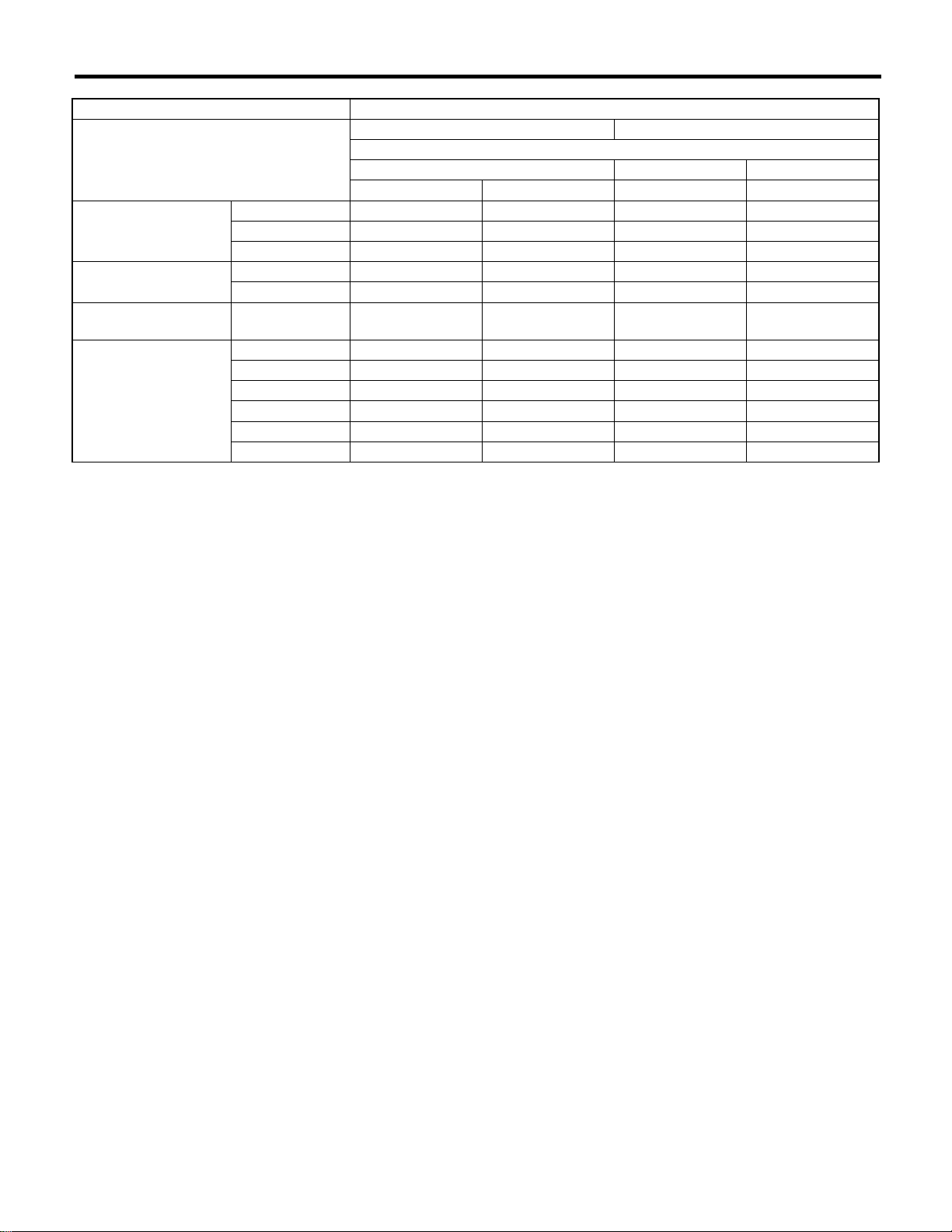
A: DIMENSIONS
Model Sedan Wagon OUTBACK STi
Overall length mm (in) 4,405 (173.4)
Overall width mm (in) 1,730 (68.1) 1,695 (66.7) 1,710 (67.3) 1,730 (68.1)
Overall height (at C.W.) mm (in)
Compartment Length mm (in) 1,890 (74.4) 1,845 (72.6) 1,890 (74.4)
Width mm (in) 1,380 (54.3)
Height mm (in) 1,180 (46.5),
Wheelbase mm (in) 2,525 (99.4)
Tread Front mm (in)
Rear mm (in) 1,475 (58.1),
Minimum road
clearance
Without catalytic
converter
With catalytic
converter
mm (in) 150 (5.9),
mm (in) 150 (5.9),
1,440 (56.7)
1,125 (44.3)★5
1,485 (58.5)
1,480 (58.3)★3
155 (6.1)★2
155 (6.1)★3
1,465 (57.7),
1,485 (58.5)★4
1,200 (47.2),
1,150 (45.3)★5
1,460 (57.5)★1,
1,465 (57.7)
1,450 (57.1)★1,
1,455 (57.3)
150 (5.9),
155 (6.1)★2
150 (5.9),
155 (6.1)★3
1,475 (58.1),
1,495 (58.9)★4
1,200 (47.2),
1,150 (45.3)★5
1,460 (57.5) 1,490 (58.7)
1,455 (57.3) 1,480 (58.3)
160 (6.3) —
160 (6.3) 155 (6.1)
1,440 (56.7)
1,180 (46.5)
★1: 1.6 L
★2: 2.0 L
★3: 2.0 L Turbo
★4: With roof rail
★5: With sun roof
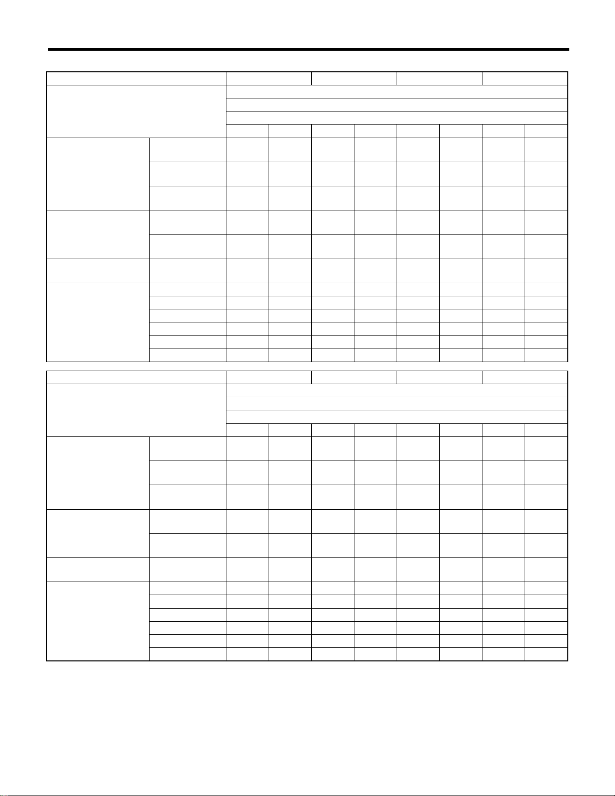
B: ENGINE
Model 1.6 L Non-Turbo 2.0 L Turbo 2.0 L 2.5 L STi
Engine type Horizontally opposed, liquid cooled, 4-cylinder, 4-stroke gasoline engine
Valve arrangement Overhead camshaft type
Bore × Stroke mm (in) 87.9 × 65.8
(3.461 × 2.591)
Displacement
Compression ratio 10.0 ± 0.2 8.0 ± 0.2 10.0 ± 0.2 8.0 ± 0.2
Firing order 1 — 3 — 2 — 4
Idle speed at
Park/Neutral position
Maximum output kW (HP)/rpm 70
Maximum torque N·m (kgf-m, ft-lb)
cm
3
(cu in)
rpm
/rpm
1,597 (97.45) 1,994 (121.67) 2,475 (151.02) 1,994 (121.67)
700 ± 100 750 ± 100 700 ± 100 700 ± 100
(94)/5,200
143
(14.6, 105.5)
/3,600
(123)/5,600
(18.8, 136.0)
/3,600
(3.62 × 2.95)
92
184
92 × 75
160
(215)/5,600
292
(29.8, 215.4)
/3,600
99.5 × 79
(3.92 × 3.11)
112
(150)/5,600
223
(22.7, 164.5)
/3,600
92 × 75
(3.62 × 2.95)
195
(261)/6,000
343
(35.0, 253.0)
/4,000
SPC-2

IMPREZA
SPECIFICATIONS
C: ELECTRICAL
Model 1.6 L Non-turbo 2.0 L Turbo 2.0 L 2.5 L STi
Ignition timing at
idling speed
Spark
plug
Generator 12V — 75A
Battery Type and
Type and
manufacturer
capacity
(5HR)
BTDC/rpm
Without
OBD
With OBD CHAMPION:
For
Europe
and South
America
Others 12V — 27AH (34B19L) —
5°±10°/700 10°±10°/700 12°±10°/750
NGK: BKR6E
(without catalyst)
CHAMPION:
RC8YC4
(with catalyst)
NGK: BKR6E-11
(with catalyst)
RC8YC4
Alternate
NGK: BKR6E-11
12V — 48AH
(55D23L)
NGK: BKR6E
(without catalyst)
CHAMPION:
RC10YC4
(with catalyst)
NGK: BKR5E-11
(with catalyst)
CHAMPION:
RC10YC4
Alternate
NGK: BKR5E-11
MT: 12V — 48AH (55D23L)
AT: 12V — 52AH (65D23L)
NGK: PFR6G
—
MT: 10°±10°/700
AT: 15°±10°/700
NGK: BKR6E (with-
out catalyst)
CHAMPION:
RC10YC4 (with cat-
alyst)
NGK: BKR5E-11
(with catalyst)
CHAMPION:
RC10YC4
Alternate
NGK: BKR6E-11
MT: 12V — 48AH
(55D23L)
AT: 12V — 52AH
(75D23L)
12°±10°/700
NGK: PFR6G
12V — 48AH
(55D23L)
—
SPC-3

IMPREZA
SPECIFICATIONS
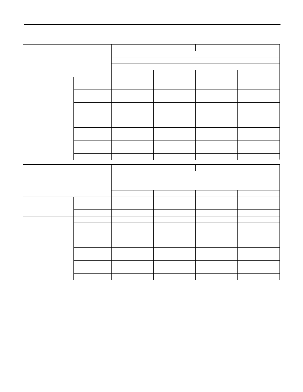
D: TRANSMISSION
Model 1.6 L Non-turbo 2.0 L Turbo 2.0 L 2.5 L STi
Transmission type 5MT 4AT 5MT 4AT 5MT 4AT 5MT 4AT 6MT
Clutch type DSPD TCC DSPD TCC DSPD TCC DSPD TCC DSPD
Gear ratio 1st
2nd
3rd
4th 1.088 0.694 1.088 0.694 0.972 0.694 1.088 0.694 1.346
5th
6th
Reverse 3.333 2.272 3.333 2.272 3.333 2.272 3.333 2.272 3.545
Dual
range
Reduction
gear (Front
drive)
Reduction
gear (Rear
drive)
1st
reduction
Final
reduction
Transfer
reduction
Final
reduction
Type of
gear
Gear
ratio
Type of
gear
Gear
ratio
Type of
gear
Gear
ratio
Type of
gear
Gear
ratio
3.454 2.785 3.454 2.785
2.062 1.545 2.062 1.545
1.448 1.000 1.448 1.000
0.825 — 0.825 — 0.738 —
————————
1.447—1.447——————
— Helical — Helical — Helical — Helical —
— 1.000 — 1.000 — 1.000 — 1.000 —
Hypoid Hypoid Hypoid Hypoid Hypoid Hypoid Hypoid Hypoid Hypoid
4.111 4.444 3.900 4.111
Helical — Helical — Helical — Helical — Helical
1.000 — 1.000 —
Hypoid Hypoid Hypoid Hypoid Hypoid Hypoid Hypoid Hypoid Hypoid
4.111 4.444 3.900 4.111
3.454,
3.166★1
1.947,
1.882★1
1.366,
1.296★1
3.900,
4.444★1
1.100,
1.000★1
3.545,
4.444★1
2.785 3.454 2.785 3.636
1.545 2.062 1.545 2.375
1.000 1.448 1.000 1.761
0.871,
0.780★1
4.111
—1.000—
4.111
3.700,
4.111★1
3.700,
4.111★1
—
4.111 3.900
4.111
0.971,
1.062★1
0.756,
0.842★1
1.100,
1.000★1
3.545,
3.900★1
5MT: 5-forward speeds with synchromesh and 1-reverse
4AT: Electronically controlled fully-automatic, 4-forward speeds and 1-reverse
6MT: 6-forward speeds with synchromesh and 1-reverse
DSPD: Dry Single Plate Diaphragm
TCC: Torque Converter Clutch
★1: Australia spec vehicle
E: STEERING
Model Turbo 2.0 L, 2.5 L OUTBACK OTHERS STi
Type Rack and Pinion
Turns, lock to lock RHD: 2.7
LHD: 3.0
Minimum turning circle m (ft) Curb to curb 11.0 (36.1) 10.8 (35.4) 10.4 (34.1) 11.0
Wall to wall 12.0 (39.4) 11.6 (38.1) 11.2 (36.7) 12.0
3.0 3.2 2.7
F: SUSPENSION
Front Macpherson strut type, Independent, Coil spring
Rear Dual-link type, Independent, Coil spring
SPC-4

IMPREZA
SPECIFICATIONS
G: BRAKE
Model 1.6 L Non-turbo 2.0 L, 2.5 L Turbo 2.0 L, STi
Service brake system Dual circuit hydraulic with vacuum suspended power unit
Front Ventilated disc brake
Rear Drum brake Disc brake Ventilated disc brake
Parking brake Mechanical on rear brakes
H: TIRE
Rim size
Tire size 175/70R14 84T
Type Steel belted radial, Tubeless
14 × 51/2JJ
185/70R14 88H
15 × 6JJ
185/65R15 88H
195/60R15 88H
16 × 61/2JJ
P205/55R16 89V
205/50R16 87V
17 × 7JJ
215/45R17 87W 225/45R17 90W
17 × 71/2JJ
215/45R17 87W
I: CAPACITY
Model 1.6 L Non-turbo 2.0 L Turbo 2.0 L 2.5 L STi
5MT 4AT 5MT 4AT 5MT 4AT 5MT 4AT 6MT
Fuel tank 2 (US gal,
Imp gal)
Engine
oil
Transmission
gear oil
Automatic transmission fluid
AT differential
gear oil
AWD rear differential gear oil
Power steering
fluid
Engine coolant 2 (US qt,
Total
capacity
Engine
oil
amount
for refill
2 (US qt,
Imp qt)
2 (US qt,
Imp qt)
2 (US qt,
Imp qt)
2 (US qt,
Imp qt)
2 (US qt,
Imp qt)
2 (US qt,
Imp qt)
2 (US qt,
Imp qt)
Imp qt)
50 (13.2, 11.0) 50 (13.2, 11.0) 60 (15.9, 13.2)
4.0 (4.2, 3.5) 4.5 (4.8, 4.0) 4.0 (4.2, 3.5)
Approx.
4.5 (4.8, 4.0)
3.5
(3.7, 3.1)
—
—
7.7
(8.1, 6.8)
—
9.3
(9.8, 8.2)
1.2
(1.3, 1.1)
7.7
(8.1, 6.8)
3.5
(3.7, 3.1)
—
—
7.0
(7.4, 6.2)
3.5
(3.7, 3.1),
4.0
(4.2, 3.5)
★1
—
—
7.4
(7.8, 6.5)
Approx. 4.0 (4.2, 3.5)
3.5
(3.7, 3.1),
—
8.4
(8.9, 7.4)
1.2
(1.3, 1.1)
7.3
(7.7, 6.4)
4.0
(4.2, 3.5)
★1
—
—
7.0
(7.4, 6.2)
—
8.4
(8.9, 7.4)
1.2
(1.3, 1.1)
0.8 (0.8, 0.7)
0.7 (0.7, 0.6)
6.9
(7.3, 6.1)
Approx.
4.0 (4.2, 3.5)
9.3
(9.8, 8.2)
1.2
(1.3, 1.1)
6.9
(7.3, 6.1)
—
(4.8, 4.0)
Approx.
(4.8, 4.0)
(4.3, 3.6)
(1.1, 0.9)
(8.1, 6.8)
4.5
4.5
4.1
—
—
1.0
7.7
★1: Dual range
SPC-5

IMPREZA
SPECIFICATIONS
J: WEIGHT
1. LHD VEHICLE
Sedan
Option code★1ECK4K0KS
Model 1.6 L
AWD
TS
5MT 4AT 5MT 4AT 5MT 4AT 5MT 4AT
Curb weight (C.W.) Front kgf (lb) 730
(1,609)
Rear kgf (lb) 520
(1,146)
Total kgf (lb) 1,250
(2,755)
Maximum permissible
axle weight (M.P.A.W.)
Maximum permissible
weight (M.P.W.)
Option Air conditioner ——❍❍❍❍❍❍
Front kgf (lb) 890
(1,962)
Rear kgf (lb) 890
(1,962)
Total kgf (lb) 1,700
(3,748)
Cruise control ————————
ABS ————————
Aluminium wheel ————————
Rear spoiler ————————
Spoiler pac ————————
750
(1,654)
520
(1,146)
1,270
(2,800)
890
(1,962)
890
(1,962)
1,700
(3,748)
750
(1,654)
520
(1,146)
1,270
(2,800)
890
(1,962)
890
(1,962)
1,700
(3,748)
770
(1,698)
520
(1,146)
1,290
(2,844)
890
(1,962)
890
(1,962)
1,700
(3,748)
750
(1,654)
520
(1,146)
1,270
(2,800)
890
(1,962)
890
(1,962)
1,700
(3,748)
770
(1,698)
520
(1,146)
1,290
(2,844)
890
(1,962)
890
(1,962)
1,700
(3,748)
740
(1,631)
535
(1,179)
1,275
(2,810)
890
(1,962)
890
(1,962)
1,700
(3,748)
760
(1,676)
535
(1,179)
1,295
(2,855)
890
(1,962)
890
(1,962)
1,700
(3,748)
Option code★1ECK4K0KS
Model 2.0 L
AWD
GX
5MT 4AT 5MT 4AT 5MT 4AT 5MT 4AT
Curb weight (C.W.) Front kgf (lb) 745
(1,643)
Rear kgf (lb) 535
(1,179)
Total kgf (lb) 1,280
(2,822)
Maximum permissible
axle weight (M.P.A.W.)
Maximum permissible
weight (M.P.W.)
Option Air conditioner ——❍❍❍❍❍❍
Front kgf (lb) 920
(2,028)
Rear kgf (lb) 910
(2,006)
Total kgf (lb) 1,760
(3,880)
Cruise control ————————
ABS ——❍❍❍❍— ❍
Aluminium wheel ——❍❍——❍❍
Rear spoiler ——————❍❍
Spoiler pac ————————
770
(1,698)
530
(1,168)
1,300
(2,866)
920
(2,028)
910
(2,006)
1,760
(3,880)
765
(1,687)
530
(1,168)
1,295
(2,855)
920
(2,028)
910
(2,006)
1,760
(3,880)
790
(1,742)
525
(1,157)
1,315
(2,899)
920
(2,028)
910
(2,006)
1,760
(3,880)
760
(1,676)
525
(1,157)
1,285
(2,833)
920
(2,028)
910
(2,006)
1,760
(3,880)
795
(1,753)
530
(1,168)
1,325
(2,921)
920
(2,028)
910
(2,006)
1,760
(3,880)
750
(1,653)
550
(1,213)
1,300
(2,866)
920
(2,028)
910
(2,006)
1,760
(3,880)
780
(1,720)
545
(1,202)
1,325
(2,922)
920
(2,028)
910
(2,006)
1,760
(3,880)
★1: For option code, refer to ID section. <Ref. to ID-5, Option code.>
SPC-6
IMPREZA
SPECIFICATIONS
Option code★1EC
Model 2.5 L 2.0 L Turbo
AWD
RS WRX STi
5MT 4AT 5MT 6MT
Curb weight (C.W.) Front kgf (lb) 760 (1,676) 785 (1,731) 815 (1,797) 875 (1,929)
Rear kgf (lb) 535 (1,179) 530 (1,168) 550 (1,213) 575 (1,268)
Total kgf (lb) 1,295 (2,855) 1,315 (2,899) 1,365 (3,009) 1,450 (3,197)
Maximum permissible
axle weight (M.P.A.W.)
Maximum permissible
weight (M.P.W.)
Option Air conditioner ————
★1: For option code, refer to ID section. <Ref. to ID-5, Option code.>
Front kgf (lb) 930 (2,050) 930 (2,050) 970 (2,138) 1,030 (2,271)
Rear kgf (lb) 910 (2,006) 910 (2,006) 920 (2,028) 920 (2,028)
Total kgf (lb)
Cruise control ————
ABS ❍❍❍❍
Aluminium wheel ————
Rear spoiler ————
Spoiler pac ————
1,780 (3,924) 1,780 (3,924) 1,850 (4,079) 1,880 (4,145)
SPC-7
IMPREZA
SPECIFICATIONS
Wagon
Option code★1ECK4K0KS
Model 1.6 L
AWD
TS
D/R 4AT D/R 4AT D/R 4AT D/R 4AT
Curb weight (C.W.) Front kgf (lb) 735
(1,620)
Rear kgf (lb) 545
(1,202)
Total kgf (lb) 1,280
(2,822)
Maximum permissible
axle weight (M.P.A.W.)
Maximum permissible
weight (M.P.W.)
Option Air conditioner ——❍❍❍❍❍❍
Front kgf (lb) 900
(1,984)
Rear kgf (lb) 910
(2,006)
Total kgf (lb) 1,730
(3,814)
Cruise control ————————
ABS ————————
Aluminium wheel ————————
Rear spoiler ————————
Spoiler pac ————————
750
(1,653)
545
(1,202)
1,295
(2,855)
900
(1,984)
910
(2,006)
1,730
(3,814)
755
(1,664)
545
(1,202)
1,300
(2,866)
900
(1,984)
910
(2,006)
1,730
(3,814)
770
(1,698)
545
(1,202)
1,315
(2,900)
900
(1,984)
910
(2,006)
1,730
(3,814)
755
(1,664)
545
(1,202)
1,300
(2,866)
900
(1,984)
910
(2,006)
1,730
(3,814)
770
(1,698)
545
(1,202)
1,315
(2,900)
900
(1,984)
910
(2,006)
1,730
(3,814)
745
(1,642)
560
(1,235)
1,305
(2,877)
900
(1,984)
910
(2,006)
1,730
(3,814)
760
(1,676)
560
(1,235)
1,320
(2,911)
900
(1,984)
910
(2,006)
1,730
(3,814)
Option code★1ECK4K0KS
Model 2.0 L
AWD
GX
D/R 4AT D/R 4AT D/R 4AT D/R 4AT
Curb weight (C.W.) Front kgf (lb) 755
(1,664)
Rear kgf (lb) 570
(1,257)
Total kgf (lb) 1,325
(2,921)
Maximum permissible
axle weight (M.P.A.W.)
Maximum permissible
weight (M.P.W.)
Option Air conditioner ——❍❍❍❍❍❍
Front kgf (lb) 920
(2,028)
Rear kgf (lb) 960
(2,116)
Total kgf (lb) 1,800
(3,969)
Cruise control ————————
ABS ——❍❍❍❍— ❍
Aluminium wheel ——❍❍——❍❍
Rear spoiler ————————
Spoiler pac ————————
770
(1,698)
565
(1,246)
1,335
(2,944)
920
(2,028)
960
(2,116)
1,800
(3,969)
775
(1,709)
565
(1,246)
1,340
(2,955)
920
(2,028)
960
(2,116)
1,800
(3,969)
790
(1,742)
560
(1,235)
1,350
(2,977)
920
(2,028)
960
(2,116)
1,800
(3,969)
780
(1,720)
570
(1,257)
1,350
(2,977)
920
(2,028)
960
(2,116)
1,800
(3,969)
795
(1,753)
565
(1,246)
1,360
(2,999)
920
(2,028)
960
(2,116)
1,800
(3,969)
760
(1,676)
580
(1,279)
1,340
(2,955)
920
(2,028)
960
(2,116)
1,800
(3,969)
780
(1,720)
575
(1,268)
1,355
(2,988)
920
(2,028)
960
(2,116)
1,800
(3,969)
D/R: Dual range
★1: For option code, refer to ID section. <Ref. to ID-5, Option code.>
SPC-8

IMPREZA
SPECIFICATIONS
Option code★1ECK4
Model 2.0 L Turbo
AWD
WRX
5MT
Curb weight (C.W.) Front kgf (lb) 805 (1,775) 825 (1,819)
Rear kgf (lb) 585 (1,290) 585 (1,290)
Total kgf (lb) 1,390 (3,065) 1,410 (3,109)
Maximum permissible
axle weight (M.P.A.W.)
Maximum permissible
weight (M.P.W.)
Option Air conditioner — ❍
D/R: Dual range
★1: For option code, refer to ID section. <Ref. to ID-5, Option code.>
Front kgf (lb) 970 (2,138) 970 (2,138)
Rear kgf (lb) 950 (2,094) 950 (2,094)
Total kgf (lb)
Cruise control ——
ABS ❍❍
Aluminium wheel ——
Rear spoiler ——
Spoiler pac ——
1,860 (4,101) 1,860 (4,101)
SPC-9
IMPREZA
SPECIFICATIONS
2. RHD VEHICLE
Sedan
Option code★1EKK1
Model 1.6 L
AWD
TS
5MT 4AT 5MT 4AT
Curb weight (C.W.) Front kgf (lb) 735 (1,621) 755 (1,665) 750 (1,654) 770 (1,698)
Rear kgf (lb) 520 (1,146) 520 (1,146) 520 (1,146) 520 (1,146)
Total kgf (lb) 1,255 (2,767) 1,275 (2,811) 1,270 (2,800) 1,290 (2,844)
Maximum permissible
axle weight (M.P.A.W.)
Maximum permissible
weight (M.P.W.)
Option Air conditioner ——❍❍
Front kgf (lb) 890 (1,962) 890 (1,962) 890 (1,962) 890 (1,962)
Rear kgf (lb) 890 (1,962) 890 (1,962) 890 (1,962) 890 (1,962)
Total kgf (lb)
Cruise control ————
ABS ❍❍——
Aluminium wheel ————
Rear spoiler ————
Spoiler pac ❍❍——
1,700 (3,748) 1,700 (3,748) 1,700 (3,748) 1,700 (3,748)
Option code★1EKK1
Model 2.0 L
AWD
GX
5MT 4AT 5MT 4AT
Curb weight (C.W.) Front kgf (lb) 765 (1,687) 790 (1,742) 770 (1,698) 795 (1,753)
Rear kgf (lb) 535 (1,179) 530 (1,168) 535 (1,179) 530 (1,168)
Total kgf (lb) 1,300 (2,866) 1,320 (2,910) 1,305 (2,877) 1,325 (2,921)
Maximum permissible
axle weight (M.P.A.W.)
Maximum permissible
weight (M.P.W.)
Option Air conditioner ❍❍❍❍
★1: For option code, refer to ID section. <Ref. to ID-5, Option code.>
Front kgf (lb) 920 (2,028) 920 (2,028) 920 (2,028) 920 (2,028)
Rear kgf (lb) 910 (2,006) 910 (2,006) 910 (2,006) 910 (2,006)
Total kgf (lb)
Cruise control ————
ABS ❍❍❍❍
Aluminium wheel ❍❍——
Rear spoiler ❍❍——
Spoiler pac ❍❍——
1,760 (3,880) 1,760 (3,880) 1,760 (3,880) 1,760 (3,880)
SPC-10

IMPREZA
SPECIFICATIONS
Option code★1KA
Model
Unladen mass (U.M.) Front kgf (lb) 750
Rear kgf (lb) 535
Total kgf (lb) 1,285
Gross vehicle mass
(G.V.M.)
Option Air conditioner ——❍❍❍❍❍
Front kgf (lb) 920
Rear kgf (lb) 910
Total kgf (lb) 1,760
Cruise control ❍❍❍❍❍❍❍
ABS ❍❍❍❍❍❍❍
Aluminium wheel ———————
Rear spoiler ——❍❍❍❍—
Spoiler pac ———————
2.0 L 2.0 L Turbo 2.5 L
AWD
GX WRX RS STi
5MT 4AT 5MT 4AT 5MT 4AT 6MT
(1,654)
(1,179)
(2,833)
(2,028)
(2,006)
(3,880)
775
(1,709)
530
(1,168)
1,305
(2,877)
920
(2,028)
910
(2,006)
1,760
(3,880)
830
(1,830)
560
(1,235)
1,390
(3,065)
970
(2,138)
920
(2,028)
1,850
(4,079)
855
(1,885)
555
(1,224)
1,410
(3,109)
970
(2,138)
920
(2,028)
1,850
(4,079)
780
(1,720)
540
(1,191)
1,320
(2,910)
930
(2,050)
910
(2,006)
1,780
(3,924)
805
(1,775)
535
(1,179)
1,340
(2,954)
930
(2,050)
910
(2,006)
1,780
(3,924)
2.0 L
Turbo
895
(1,973)
575
(1,268)
1,470
(3,241)
1,030
(2,271)
920
(2,028)
1,880
(4,145)
Option code★1EK
Model 2.0 L Turbo
AWD
WRX STi
5MT 6MT
Curb weight (C.W.) Front kgf (lb) 830 (1,830) 895 (1,973)
Rear kgf (lb) 560 (1,235) 575 (1,268)
Total kgf (lb) 1,390 (3,065) 1,470 (3,241)
Maximum permissible
axle weight (M.P.A.W.)
Maximum permissible
weight (M.P.W.)
Option Air conditioner ❍❍
★1: For option code, refer to ID section. <Ref. to ID-5, Option code.>
Front kgf (lb) 970 (2,138) 1,030 (2,271)
Rear kgf (lb) 920 (2,028) 920 (2,028)
Total kgf (lb)
Cruise control ——
ABS ❍❍
Aluminium wheel ——
Rear spoiler ❍ —
Spoiler pac ——
1,850 (4,079) 1,880 (4,145)
SPC-11

IMPREZA
SPECIFICATIONS
Wagon
Option code★1EKK1
Model 1.6 L
AWD
TS
D/R4ATD/R4AT
Curb weight (C.W.) Front kgf (lb) 740 (1,631) 755 (1,664) 755 (1,664) 770 (1,698)
Rear kgf (lb) 545 (1,202) 545 (1,202) 545 (1,202) 545 (1,202)
Total kgf (lb) 1,285 (2,833) 1,300 (2,866) 1,300 (2,866) 1,315 (2,900)
Maximum permissible
axle weight (M.P.A.W.)
Maximum permissible
weight (M.P.W.)
Option Air conditioner ——❍❍
Option code★1EKK1
Model 2.0 L
Curb weight (C.W.) Front kgf (lb) 775 (1,709) 790 (1,742) 780 (1,720) 795 (1,753)
Maximum permissible
axle weight (M.P.A.W.)
Maximum permissible
weight (M.P.W.)
Option Air conditioner ❍❍❍❍
Front kgf (lb) 900 (1,984) 900 (1,984) 900 (1,984) 900 (1,984)
Rear kgf (lb) 910 (2,006) 910 (2,006) 910 (2,006) 910 (2,006)
Total kgf (lb)
Cruise control ————
ABS ❍❍——
Aluminium wheel ————
Rear spoiler ————
Spoiler pac ————
Rear kgf (lb) 570 (1,257) 565 (1,246) 570 (1,257) 565 (1,246)
Total kgf (lb) 1,345 (2,965) 1,355 (2,987) 1,350 (2,977) 1,360 (2,999)
Front kgf (lb) 920 (2,028) 920 (2,028) 920 (2,028) 920 (2,028)
Rear kgf (lb) 960 (2,116) 960 (2,116) 960 (2,116) 960 (2,116)
Total kgf (lb)
Cruise control ————
ABS ❍❍❍❍
Aluminium wheel ❍❍——
Rear spoiler ————
Spoiler pac ❍❍——
1,730 (3,814) 1,730 (3,814) 1,730 (3,814) 1,730 (3,814)
AWD
GX
D/R4ATD/R4AT
1,800 (3,968) 1,800 (3,968) 1,800 (3,968) 1,800 (3,968)
D/R: Dual range
★1: For option code, refer to ID section. <Ref. to ID-5, Option code.>
SPC-12

IMPREZA
SPECIFICATIONS
Option code★1KA
Model 2.0 L 2.0 L Turbo
AWD
GX OUTBACK WRX
D/R 4AT D/R 4AT 5MT 4AT
Unladen mass (U.M.) Front kgf (lb) 760 (1,676) 775 (1,709) 750 (1,653) 765 (1,687) 825 (1,819) 850 (1,874)
Rear kgf (lb) 570 (1,257) 565 (1,246) 570 (1,257) 570 (1,257) 585 (1,290) 585 (1,290)
Total kgf (lb) 1,330
(2,932)
Gross vehicle mass
(G.V.M.)
Option Air conditioner ————❍❍
Front kgf (lb) 920 (2,028) 920 (2,028) 920 (2,028) 920 (2,028) 970 (2,138) 970 (2,138)
Rear kgf (lb) 960 (2,116) 960 (2,116) 960 (2,116) 960 (2,116) 950 (2,094) 950 (2,094)
Total kgf (lb) 1,800
(3,968)
Cruise control ❍❍❍❍❍❍
ABS ❍❍❍❍❍❍
Aluminium wheel ——————
Rear spoiler ——————
Spoiler pac ——————
1,340
(2,954)
1,800
(3,968)
1,320
(2,910)
1,800
(3,968)
1,335
(2,943)
1,800
(3,968)
1,410
(3,109)
1,860
(4,101)
1,435
(3,164)
1,860
(4,101)
Option code★1EK
Model 2.0 L Turbo
AWD
WRX
5MT
Curb weight (C.W.) Front kgf (lb) 825 (1,819)
Rear kgf (lb) 585 (1,290)
Total kgf (lb) 1,410 (3,109)
Maximum permissible
axle weight (M.P.A.W.)
Maximum permissible
weight (M.P.W.)
Option Air conditioner ❍
D/R: Dual range
★1: For option code, refer to ID section. <Ref. to ID-5, Option code.>
Front kgf (lb) 970 (2,138)
Rear kgf (lb) 950 (2,094)
Total kgf (lb)
Cruise control —
ABS ❍
Aluminium wheel —
Rear spoiler —
Spoiler pac —
1,860 (4,101)
SPC-13

SPECIFICATIONS
IMPREZA
SPC-14

IDENTIFICATION
1. Identification................................................................................................2
ID
Page

IDENTIFICATION
IDENTIFICATION
1. Identification
A: IDENTIFICATION
2. MEANING OF V.I.N.
The meaning of the VIN is as follows:
• Europe, Australia and General (Except GCC)
]JF1GD5LJ32G002001[
The starting and ending brackets ( ][ ) are stop marks.
Digits Code Meaning Details
1 to 3 JF1 Manufacturer body area JF1: Passenger car, FHI made
4 G Car line IMPREZA
5 D Body type D: 4 Door Sedan
G: Wagon
6 5 Displacement 5: 1.6 L AWD
9: 2.0 L AWD
A: 2.0 L AWD Turbo
B: 2.0 L AWD High-power Turbo
E: 2.5 L AWD
7 L Steering position K: RHD (Right-hand drive)
L: LHD (Left-hand drive)
8 J Engine & transmission R: SOHC MPI 4-speed AT
J: SOHC MPI Full-time AWD 5-speed MT
K: SOHC MPI Full-time AWD 5-speed MT Dual range
D: DOHC Turbo Full-time AWD 5-speed MT
H: DOHC Turbo Full-time AWD 6-speed MT
P: DOHC Turbo 4-speed AT
9 3 Drive type 3: Full-time AWD Single range
4: Full-time AWD Dual range
5: AWD AT
10 2 Model year 2: 2002MY
3: 2003MY
11 G Factory location G: FHI (Gunma)
12 to 17 002001 Serial number —
• GCC countries (Saudi Arabia, etc.)
]JF1GD45MX2G002001[
The starting and ending brackets ( ][ ) are stop marks.
Digits Code Meaning Details
1 to 3 JF1 Manufacturer body area JF1: Passenger car, FHI made
4 G Car line IMPREZA
5 D Body type D: 4 Door Sedan
G: Wagon
6 4 Displacement 4: 1.6 L AWD
8: 2.0 L AWD
75 Grade 5: TS
7: GX
8 M Restraint M: Manual belts, dual airbag
9 X Check digit —
10 2 Model year 2: 2002MY
3: 2003MY
11 G Transmission type G: Full-time AWD 5-speed MT single range
H: Full-time AWD 4-speed AT
J: Full-time AWD 5-speed MT dual range
12 to 17 002001 Serial number —
ID-2

IDENTIFICATION
IDENTIFICATION
3. MODEL NUMBER PLATE
The model number plate indicates: the applied model, the option code, the trim code, the engine type, the
transmission type, and the exterior color code. This information is helpful when placing orders for parts.
GD9BL7R
Digits Code Meaning Details
1 G Series IMPREZA
2 D Body style D: 4 Door Sedan
G: Wagon
3 9 Engine displacement
Drive system
Suspension system
4 B Minor change 2002MY
5 L Destination K: Right-hand drive market
67 Grade 4: TS
7 R Transmission, fuel feed
system
5: 1.6 L AWD
9: 2.0 L AWD
A: 2.0 L AWD Turbo
B: 2.0 L AWD High-power Turbo
E: 2.5 L AWD
L: Left-hand drive market
5: GX
6: RS
7: OUTBACK
8: WRX
E: STi
R: SOHC MPI 4-speed AT
J: SOHC MPI 5-speed MT AWD
K: SOHC MPI 5-speed MT Dual range
P: DOHC B MPI 4-speed AT
D: DOHC B MPI 5-speed MT AWD
H: DOHC B MPI 6-speed MT AWD
The engine and transmission type are as follows:
• Engine
EJ161RX3AA
Digits Code Meaning Details
1 and 2 EJ Engine type EJ: 4 cylinders
3 and 4 16 Displacement 16: 1.6 L
20: 2.0 L
25: 2.5 L
5 1 Fuel feed system 1: D-MPI SOHC-A
5: MPI Turbo
7: MPI High-power Turbo
6 R Detailed specifications Used when ordering parts. See the parts catalog for details.
7 X Transmission W: MT
X: AT
8 to 10 3AA Detailed specifications Used when ordering parts. See the parts catalog for details.
ID-3

IDENTIFICATION
IDENTIFICATION
• Transmission
TY856WN2AA
Digits Code Meaning Details
1 T Transmission T: Transmission
2 Y Transmission type Y: Full-time AWD MT center differential
V: Full-time AWD AT center differential
Z: Full-time AWD AT MPT
3 and 4 85 Classification 75: 5MT
85: 6MT
1B: AT
5 6 Series MT 4: 5MT
6: 6MT
AT 4: AT
6 W Transmission specifica-
tions
7 to 10 N2AA Detailed specifications Used when ordering parts. See the parts catalog for details.
• Rear differential 1
V: Full-time AWD 5-speed MT with viscous coupling center differential single range
X: Full-time AWD 5-speed MT with viscous coupling center differential dual range
W: Full-time AWD 6-speed MT with viscous coupling center differential single range
Z: Full-time AWD 4-speed AT with MPT
Y: Full-time AWD 4-speed AT with VTD
VA1REJ
Digits Code Meaning Details
1 V For AWD V: AWD
2 A Type A: A type
3 1 Hypoid gear diameter
mm (in)
4 R Installation position R: Rear
5 E Reduction gear ratio B: 3.900
6 J Specification differ-
ences
1: 152 (6.0) dia.
2: 160 (6.3) dia.
E: 4.111
F: 4.444
J: Case B
• Rear differential 2
EG
Code Reduction gear ratio LSD
EG 3.900 No
ER 3.700 Viscous
EM 4.444
EJ 4.111 Viscous
EF 3.545 Viscous
HG 3.500
HJ 3.545
SURETRAC
SURETRAC
SURETRAC
ID-4

IDENTIFICATION
• Option code
ECPS
Digits Code Meaning Details
1 to 2 EC Destination EC: EC
KO: KO
K4: K4
KS: KS
EK: EK
KA: KA
K1: K1
3 to 4 PS Main option of vehicle —
IDENTIFICATION
ID-5

IDENTIFICATION
IDENTIFICATION
ID-6

2002 IMPREZA STi SERVICE MANUAL QUICK REFERENCE INDEX
ENGINE 2 SECTION
FUEL INJECTION (FUEL SYSTEMS) FU(TURBO)
This service manual has been prepared
to provide SUBARU service personnel
with the necessary information and data
for the correct maintenance and repair
of SUBARU vehicles.
This manual includes the procedures
for maintenance, disassembling, reassembling, inspection and adjustment of
components and diagnostics for guidance of experienced mechanics.
Please peruse and utilize this manual
fully to ensure complete repair work for
satisfying our customers by keeping
their vehicle in optimum condition.
When replacement of parts during
repair work is needed, be sure to use
SUBARU genuine parts.
EMISSION CONTROL
(AUX. EMISSION CONTROL DEVICES)
INTAKE (INDUCTION) IN(TURBO)
MECHANICAL ME(STi)
ENGINE (DIAGNOSTICS) EN(TURBO)
EC(TURBO)
All information, illustration and specifications contained in this manual are
based on the latest product information
available at the time of publication
approval.
FUJI HEAVY INDUSTRIES LTD. G1841GE3


FUEL INJECTION (FUEL SYSTEMS)
FU(TURBO)
1. General Description
2. Throttle Body
3. Intake Manifold
4. Engine Coolant Temperature Sensor
5. Crankshaft Position Sensor
6. Camshaft Position Sensor
7. Knock Sensor
8. Throttle Position Sensor
9. Mass Air Flow and Intake Air Temperature Sensor
10. Pressure Sensor
11. Idle Air Control Solenoid Valve
12. Fuel Injector
13. Tumble Generator Valve Assembly ............................................................2
14. Tumble Generator Valve Actuator...............................................................3
15. Wastegate Control Solenoid Valve
16. Front Oxygen (A/F) Sensor
17. Rear Oxygen Sensor
18. Exhaust Temperature Sensor .....................................................................4
19. Engine Control Module
20. Main Relay
21. Fuel Pump Relay
22. Fuel Pump Controller
23. Fuel
24. Fuel Tank
25. Fuel Filler Pipe
26. Fuel Pump
27. Fuel Level Sensor
28. Fuel Sub Level Sensor
29. Fuel Filter
30. Fuel Cut Valve
31. Fuel Damper Valve
32. Fuel Delivery, Return and Evaporation Lines
33. Fuel System Trouble in General
34. Variable Valve Timing Camshaft Positon Sensor .......................................5
35. Variable Valve Timing Solenoid Valve ........................................................6
Page

TUMBLE GENERATOR VALVE ASSEMBLY
FUEL INJECTION (FUEL SYSTEMS)
13.Tumble Generator Valve Assembly
A: REMOVAL
2. STI MODEL
NOTE:
Tumble generator valve actuator and sensor are
not applied to STi model.
B: INSTALLATION
2. STI MODEL
NOTE:
Tumble generator valve actuator and sensor are
not applied to STi model.
FU(TURBO)-2

TUMBLE GENERATOR VALVE ACTUATOR
14.Tumble Generator Valve Actuator
A: REMOVAL
3. STI MODEL
NOTE:
Tumble generator valve actuator is not applied to
STi model.
B: INSTALLATION
3. STI MODEL
NOTE:
Tumble generator valve actuator is not applied to
STi model.
FUEL INJECTION (FUEL SYSTEMS)
FU(TURBO)-3

EXHAUST TEMPERATURE SENSOR
FUEL INJECTION (FUEL SYSTEMS)
18.Exhaust Temperature Sensor
A: REMOVAL
2. STI MODEL
NOTE:
Exhaust temperature sensor is not applied to STi
model.
B: INSTALLATION
2. STI MODEL
NOTE:
Exhaust temperature sensor is not applied to STi
model.
FU(TURBO)-4

VARIABLE VALVE TIMING CAMSHAFT POSITON SENSOR
34.Variable Valve Timing Camshaft Positon Sensor
A: REMOVAL
1) Disconnect the ground cable from battery.
2) Remove the intercooler. <Ref. to IN(TURBO)-
10, REMOVAL, Intercooler.>
3) Remove the intake manifold. <Ref. to FU(TUR-
BO)-15, REMOVAL, Intake Manifold.>
4) Disconnect the variable valve timing camshaft
position sensor connector.
5) Remove the variable valve timing camshaft posi-
tion sensor.
FUEL INJECTION (FUEL SYSTEMS)
B: INSTALLATION
Install in the reverse order of removal.
EN1533
FU(TURBO)-5

VARIABLE VALVE TIMING SOLENOID VALVE
FUEL INJECTION (FUEL SYSTEMS)
35.Variable Valve Timing Solenoid Valve
A: REMOVAL
Refer to following procedure for removal. <Ref. to
ME(STi)-59, REMOVAL, Camshaft.>
B: INSTALLATION
Install in the reverse order of removal.
FU(TURBO)-6

EMISSION CONTROL
(AUX. EMISSION CONTROL DEVICES)
EC(TURBO)
1. General Description
2. Front Catalytic Converter
3. Rear Catalytic Converter
4. Precatalytic Converter.................................................................................2
5. Canister
6. Purge Control Solenoid Valve
7. Two-way Valve
Page

PRECATALYTIC CONVERTER
EMISSION CONTROL (AUX. EMISSION CONTROL DEVICES)
4. Precatalytic Converter
A: REMOVAL
2. STI MODEL
NOTE:
Precatalytic converter is not applied to STi model.
B: INSTALLATION
2. STI MODEL
NOTE:
Precatalytic converter is not applied to STi model.
EC(TURBO)-2

INTAKE (INDUCTION)
IN(TURBO)
1. General Description ....................................................................................2
2. Air Cleaner
3. Air Intake Duct
4. Intake Duct
5. Intercooler
6. Turbocharger
7. Air By-pass Valve
8. Resonator Chamber
9. Intercooler Water Tank................................................................................3
Page

GENERAL DESCRIPTION
INTAKE (INDUCTION)
1. General Description
A: COMPONENT
5. INTERCOOLER WATER TANK
(2)
(1)
T
T
EN1545
(1) Water tank assembly (2) Water tank cap Tightening torque: N·m (kgf-m, ft-lb)
T: 6.0 (0.61, 4.4)
IN(TURBO)-2

INTERCOOLER WATER TANK
9. Intercooler Water Tank
A: REMOVAL
1) Disconnect the ground cable from battery.
G6M0095
2) Remove the trunk trim. <Ref. to EI-52, REMOV-
AL, Trunk Trim.>
3) Disconnect the water tank connector.
INTAKE (INDUCTION)
EN1541
4) Remove the two water tank installation bolts.
EN1542
5) Remove the hose between body and water tank,
then remove the water tank.
B: INSTALLATION
Install in the reverse order of removal.
Tightening torque:
6.0 N·m (0.61 kgf-m, 4.4 ft-lb)
C: INSPECTION
1) Make sure the hose is not deformed, damaged,
cracked or clogged.
2) Make sure the water tank is not damaged or
cracked
IN(TURBO)-3

INTAKE (INDUCTION)
INTERCOOLER WATER TANK
IN(TURBO)-4

MECHANICAL
1. General Description ....................................................................................2
2. Compression.............................................................................................22
3. Idle Speed .................................................................................................23
4. Ignition Timing...........................................................................................24
5. Intake Manifold Vacuum............................................................................25
6. Engine Oil Pressure ..................................................................................26
7. Fuel Pressure............................................................................................27
8. Valve Clearance........................................................................................28
9. Engine Assembly ......................................................................................32
10. Engine Mounting .......................................................................................41
11. Preparation for Overhaul...........................................................................42
12. V-belt.........................................................................................................43
13. Crankshaft Pulley ......................................................................................45
14. Belt Cover .................................................................................................46
15. Timing Belt Assembly................................................................................47
16. Camshaft Sprocket....................................................................................56
17. Crankshaft Sprocket..................................................................................58
18. Camshaft ...................................................................................................59
19. Cylinder Head Assembly...........................................................................65
20. Cylinder Block ...........................................................................................73
21. Engine Trouble in General ........................................................................92
22. Engine Noise.............................................................................................97
ME(STi)
Page

MECHANICAL
1. General Description
A: SPECIFICATIONS
GENERAL DESCRIPTION
Horizontally opposed, liquid cooled, 4-cylinder,
4-stroke gasoline engine
1,994 (121.67)
981 — 1,177 (10 — 12, 142 — 171)
700±50 (No load)
750±50 (A/C switch ON)
Engine
Type
Valve arrangement Belt driven, double overhead camshaft, 4-valve/cylinder
Bore x Stroke mm (in) 92 x 75 (3.62 x 2.95)
Piston displacement
Compression ratio 8.0
Compression pressure
(at 200 — 300 rpm) kPa (kg/cm
Number of piston rings Pressure ring: 2, Oil ring: 1
Opening
Intake valve timing
Closing
Exhaust valve timing
Valve clearance
Idling speed [At neutral position] rpm
Firing order 1 → 3 → 2 → 4
Ignition timing BTDC/rpm 12°±3°/700 rpm
Opening 58° BBDC
Closing 10° ATDC
Intake mm (in) 0.20±0.02 (0.0079±0.0008)
Exhaust mm (in) 0.25±0.02 (0.0098±0.0008)
cm
3
(cu in)
2
, psi)
Max. retard ATDC 6°
Min. advance BTDC 29°
Max. retard ABDC 68°
Min. advance ABDC 33°
NOTE:
STD: Standard I.D.: Inner Diameter O.D.: Outer Diameter OS: Oversize US: Undersize
ME(STi)-2

Belt tension
adjuster
Belt tensioner
Camshaft
Cylinder
head
Valve seat
Valve guide
Valve
Valve
spring
GENERAL DESCRIPTION
MECHANICAL
Protrusion of adjuster rod 5.2 — 6.2 mm (0.205 — 0.244 in)
Spacer O.D. 17.955 — 17.975 mm (0.7069 — 0.7077 in)
Tensioner bush I.D. 18.0 — 18.08 mm (0.7087 — 0.7118 in)
Clearance between spacer and bush
Side clearance of spacer
Bend limit 0.020 mm (0.0079 in)
Thrust clearance
Intake
Cam lobe height
Exhaust
Journal O.D. STD
Oil clearance
Surface warpage limit 0.05 mm (0.0020 in)
Surface grinding limit 0.1 mm (0.004 in)
Standard height 127.5 mm (5.02 in)
Refacing angle 90°
Intake
Contacting width
Exhaust
Inner diameter 6.000 — 6.012 mm (0.2362 — 0.2367 in)
Protrusion above head 12.0 — 12.4 mm (0.472 — 0.488 in)
Intake
Head edge thickness
Exhaust
Stem diameter
Stem oil clearance
Overall length
Free length 43.89 mm (1.7279 in)
Squareness 2.5°, 1.9 mm (0.075 in)
Tension/spring height
STD
Limit — 0.15 mm (0.0059 in)
STD 0.025 — 0.125 mm (0.0010 — 0.0049 in)
Limit 0.175 mm (0.0069 in)
STD 0.2 — 0.55 mm (0.0079 — 0.0217 in)
Limit 0.81 mm (0.0319 in)
STD 0.015 — 0.070 mm (0.0006 — 0.0028 in)
Limit 0.10 mm (0.0039 in)
STD 45.25 — 45.35 mm (1.781 — 1.785 in)
Limit 45.15 mm (1.778 in)
STD 45.60 — 45.70 mm (1.795 — 1.799 in)
Limit 45.50 mm (1.791 in)
Front 37.946 — 37.963 mm (1.4939 — 1.4946 in)
Center
rear
STD 0.037 — 0.072 mm (0.0015 — 0.0028 in)
Limit 0.10 mm (0.0039 in)
STD 1.0 mm (0.039 in)
Limit 1.7 mm (0.067 in)
STD 1.5 mm (0.059 in)
Limit 2.2 mm (0.087 in)
STD 1.2 mm (0.047 in)
Limit 0.8 mm (0.031 in)
STD 1.5 mm (0.059 in)
Limit 0.8 mm (0.031 in)
Intake 5.962 — 5.970 mm (0.2347 — 0.2350 in)
Exhaust 5.945 — 5.960 mm(0.2341 — 0.2346 in)
Intake 0.030 — 0.050 mm (0.0012 — 0.0020 in)
Exhaust 0.040 — 0.050 mm (0.0016 — 0.0020 in)
Intake 104.4 mm (4.110 in)
Exhaust 104.7 mm (4.122 in)
Set 220.7±15.7 N (22.5±1.6 kgf, 49.6±3.5 lb)/36.0 mm (1.417 in)
Lift 582±29 N (59.3±3.0 kgf, 130.8±6.5 lb)/24.65 mm (0.970 in)
29.946 — 29.963 mm (1.1790 — 1.1796 in)
ME(STi)-3

MECHANICAL
Surface warpage limit (mating with cylinder head) 0.05 mm (0.0020 in)
Surface grinding limit 0.1 mm (0.004 in)
Cylinder bore STD
Cylinder
block
Piston Outer diameter
Piston pin
Piston ring
Connecting
rod
Connecting
rod bearing
Connecting
rod bushing
Taper
Out-of-roundness
Piston clearance
Enlarging (boring) limit 0.5 mm (0.020 in)
Standard clearance between piston
pin and hole in piston
Degree of fit
Piston ring gap
Clearance between piston ring and piston ring
groove
Bend twist per 100 mm (3.94 in) in
length
Side clearance
Oil clearance
Thickness at center portion
Clearance between piston pin and
bushing
GENERAL DESCRIPTION
A 92.005 — 92.015 mm (3.6222 — 3.6226 in)
B 91.995 — 92.005 mm (3.6218 — 3.6222 in)
STD 0.015 mm (0.0006 in)
Limit 0.050 mm (0.0020 in)
STD 0.010 mm (0.0004 in)
Limit 0.050 mm (0.0020 in)
STD 0.010 — 0.030 mm (0.0004 — 0.0012 in)
Limit 0.050 mm (0.0020 in)
STD
0.25 mm (0.0098 in)
OS
0.50 mm (0.0197 in)
OS
Top ring
Second
ring
Oil ring
Top ring
Second
ring
A 91.985 — 91.995 mm (3.6214 — 3.6218 in)
B 91.975 — 91.985 mm (3.6211 — 3.6214 in)
92.225 — 92.235 mm (3.6309 — 3.6313 in)
92.475 — 92.485 mm (3.6407 — 3.6411 in)
STD 0.004 — 0.008 mm (0.0002 — 0.0003 in)
Limit 0.020 mm (0.0008 in)
Piston pin must be fitted into position with thumb at 20°C
STD 0.20 — 0.25 mm (0.0079 — 0.0098 in)
Limit 1.0 mm (0.039 in)
STD 0.35 — 0.50 mm (0.0138 — 0.0197 in)
Limit 1.0 mm (0.039 in)
STD 0.20 — 0.50 mm (0.0079 — 0.0197 in)
Limit 1.5 mm (0.059 in)
STD 0.040 — 0.080 mm (0.0016 — 0.0031 in)
Limit 0.15 mm (0.0059 in)
STD 0.030 — 0.070 mm (0.0012 — 0.0028 in)
Limit 0.15 mm (0.0059 in)
Limit 0.10 mm (0.0039 in)
STD 0.070 — 0.330 mm (0.0028 — 0.0130 in)
Limit 0.4 mm (0.016 in)
STD 0.020 — 0.046 mm (0.0008 — 0.0018 in)
Limit 0.05 mm (0.0020 in)
STD 1.486 — 1.498 mm (0.0585 — 0.0590 in)
0.03 mm
(0.0012
in) US
0.05 mm
(0.0020
in) US
0.25 mm
(0.0098
in) US
STD 0 — 0.022 mm (0 — 0.0009 in)
Limit 0.030 mm (0.0012 in)
1.505 — 1.509 mm (0.0593 — 0.0594 in)
1.515 — 1.519 mm (0.0596 — 0.0598 in)
1.615 — 1.619 mm (0.0636 — 0.0637 in)
(68°F).
ME(STi)-4

Crankshaft
Crankshaft
bearing
GENERAL DESCRIPTION
Bend limit 0.035 mm (0.0014 in)
Crank pin and crank journal
Crank pin outer diameter
Crank journal outer diameter
Thrust clearance
Oil clearance
Crankshaft bearing thickness
Out-of-roundness 0.020 mm (0.0008 in) or less
Grinding limit 0.25 mm (0.0098 in)
STD 51.984 — 52.000 mm (2.0466 — 2.0472 in)
0.03 mm
#1, #3, #5
#2, #4
#1, #3
#2, #4, #5
(0.0012
in) US
0.05 mm
(0.0020
in) US
0.25 mm
(0.0098
in) US
STD 59.992 — 60.008 mm (2.3619 — 2.3625 in)
0.03 mm
(0.0012
in) US
0.05 mm
(0.0020
in) US
0.25 mm
(0.0098
in) US
STD 59.992 — 60.008 mm (2.3619 — 2.3625 in)
0.03 mm
(0.0012
in) US
0.05 mm
(0.0020
in) US
0.25 mm
(0.0098
in) US
STD 0.030 — 0.115 mm (0.0012 — 0.0045 in)
Limit 0.25 mm (0.0098 in)
STD 0.010 — 0.030 mm (0.0004 — 0.0012 in)
Limit 0.040 mm (0.0016 in)
STD 1.998 — 2.011 mm (0.0787 — 0.0792 in)
0.03 mm
(0.0012
in) US
0.05 mm
(0.0020
in) US
0.25 mm
(0.0098
in) US
STD 2.000 — 2.013 mm (0.0787 — 0.0793 in)
0.03 mm
(0.0012
in) US
0.05 mm
(0.0020
in) US
0.25 mm
(0.0098
in) US
51.954 — 51.970 mm (2.0454 — 2.0461 in)
51.934 — 51.950 mm (2.0446 — 2.0453 in)
51.734 — 51.750 mm (2.0368 — 2.0374 in)
59.962 — 59.978 mm (2.3607 — 2.3613 in)
59.942 — 59.958 mm (2.3599 — 2.3605 in)
59.742 — 59.758 mm (2.3520 — 2.3527 in)
59.962 — 59.978 mm (2.3607 — 2.3613 in)
59.942 — 59.958 mm (2.3599 — 2.3605 in)
59.742 — 59.758 mm (2.3520 — 2.3527 in)
2.017 — 2.020 mm (0.0794 — 0.0795 in)
2.027 — 2.030 mm (0.0798 — 0.0799 in)
2.127 — 2.130 mm (0.0837 — 0.0839 in)
2.019 — 2.022 mm (0.0795 — 0.0796 in)
2.029 — 2.032 mm (0.0799 — 0.0800 in)
2.129 — 2.132 mm (0.0838 — 0.0839 in)
MECHANICAL
ME(STi)-5

MECHANICAL
B: COMPONENT
1. TIMING BELT
GENERAL DESCRIPTION
(17)
T1
T1
T5
(12)
(14)
T4
T5
(13)
(8)
(7)
T2
(9)
T4
(2)
T5
T2
T1
T5
(6)
T3
(2)
T3
(11)
T1
T4
(14)
(10)
(1)
(2)
T2
(3)
(4)
(5)
T1
(2)
T2
(15)
(16)
T6
(1) Right-hand belt cover No. 2 (9) Right-hand intake camshaft
(2) Timing belt guide (18) Crankshaft pulley
(18)
T1
EN1192
(17) Right-hand belt cover
sprocket
(3) Crankshaft sprocket (10) Left-hand intake camshaft
(4) Left-hand belt cover No. 2 Tightening torque: N·m (kgf-m, ft-lb)
(5) Tensioner bracket (11) Left-hand exhaust camshaft
(6) Automatic belt tension adjuster
ASSY
sprocket
T1: 5 (0.5, 3.6)
sprocket
T2: 10 (1.0, 7)
(12) Timing belt T3: 25 (2.5, 18.1)
(7) Belt idler (13) Belt idler No. 2 T4: 39 (4.0, 28.9)
(8) Right-hand exhaust camshaft
sprocket
(14) Belt idler T5: 98 (10, 72.4)
(15) Left-hand belt cover T6: <Ref. to ME(STi)-45, Installation,
(16) Front belt cover
Crankshaft Pulley.>
ME(STi)-6

GENERAL DESCRIPTION
MECHANICAL
ME(STi)-7

GENERAL DESCRIPTION
MECHANICAL
2. CYLINDER HEAD AND CAMSHAFT
T2
(2)
T5
(1)
T3
(3)
(7)
T3
(11)
(28)
(6)
(15)
(9)
(16)
(13)
(4)
T3
(14)
(17)
(8)
(5)
T5
(11)
(28)
(10)
T1
(10)
(18)
T5
(21)
(20)
(12)
(13)
(24)
(25)
(26)
T4
(27)
(22)
T2
T3
(19)
ME(STi)-8
T5
T2
(23)
EN1193

GENERAL DESCRIPTION
MECHANICAL
(1) Rocker cover (RH) (13) Cylinder head gasket (25) Gasket
(2) Rocker cover gasket (RH) (14) Cylinder head (LH) (26) Oil filler duct
(3) Variable valve timing solenoid
valve assembly (RH)
(4) Intake camshaft cap (RH) (17) Variable valve timing solenoid
(5) Intake camshaft (RH) Tightening torque: N·m (kgf-m, ft-lb)
(6) Exhaust camshaft cap (Front RH) (18) Intake camshaft cap (LH) T1: <Ref. to ME(STi)-65, Installation,
(7) Exhaust camshaft cap (Center
RH)
(8) Exhaust camshaft cap (Rear RH) T3: 10 (1.0, 7)
(9) Exhaust camshaft (RH) (21) Exhaust camshaft cap (Rear LH) T4: 6.4 (0.65, 4.7)
(10) Cylinder head bolt (22) Rocker cover gasket (LH) T5: 20 (2.0, 14.5)
(11) Oil seal (23) Rocker cover (LH)
(12) Cylinder head (RH) (24) Oil filler cap
(15) Intake camshaft (LH) (27) O-ring
(16) Exhaust camshaft (LH) (28) Stud bolt
valve assembly (LH)
(19) Exhaust camshaft cap (Front LH)
(20) Exhaust camshaft cap (Center
LH)
Cylinder Head Assembly.>
T2: 5 (0.5, 3.6)
ME(STi)-9

GENERAL DESCRIPTION
MECHANICAL
3. CYLINDER HEAD AND VALVE ASSEMBLY
(1)
(2)
(12)
(4)
(3)
(10)
(6)
(11) (4) (5) (6) (7) (8) (9)
(4)
(12)
(11)
(4)
(5) (6)
(10)
(6)
(7)
(8)
(7)
(9)
(8)
(9)
(7)
(8)
(9)
(1) Exhaust valve (5) Intake valve oil seal (9) Valve lifter
(2) Intake valve (6) Valve spring (10) Exhaust valve oil seal
(3) Cylinder head (7) Retainer (11) Intake valve guide
(4) Valve spring seat (8) Retainer key (12) Exhaust valve guide
EN1194
ME(STi)-10

4. CYLINDER BLOCK
GENERAL DESCRIPTION
MECHANICAL
EN0144
(1) Oil pressure switch (15) Oil cooler Tightening torque: N·m (kgf-m, ft-lb)
(2) Cylinder block (RH) (16) Waster by-pass pipe T1: 5 (0.5, 3.6)
(3) Service hole plug (17) Connector T2: 6.4 (0.65, 4.7)
(4) Gasket (18) Oil strainer T3: 10 (1.0, 7)
(5) Oil separator cover (19) Gasket T4: 25 (2.5, 18.1)
(6) Water by-pass pipe (20) Oil pan T5: 47 (4.8, 34.7)
(7) Oil pump (21) Drain plug T6: 69 (7.0, 50.6)
(8) Front oil seal (22) Metal gasket T7: First 12 (1.2, 8.7)
(9) Rear oil seal (23) Oil level gauge guide
(10) O-ring (24) Oil filter T8: 16 (1.6, 11.6)
(11) Service hole cover (25) Gasket T9: 44 (4.5, 33)
(12) Cylinder block (LH) (26) Water pump hose T10: 25 (2.5, 18.1)
(13) Water pump (27) Plug T11: 55 (5.5, 40)
(14) Baffle plate
Second 12 (1.2, 8.7)
ME(STi)-11

MECHANICAL
5. CRANKSHAFT AND PISTON
(3)
(4)
(5)
(8)
(6)
(9)
T1
(12)
GENERAL DESCRIPTION
(1)
(8)
(7)
(10)
(11)
(11)
(2)
(13)
(11)
(12)
(9)
T2
T1
(6)
(8)
(5)
(4)
(3)
EN1519
(14)
(11)
(10)
(8)
(7)
(17)
(16)
(15)
(16)
(15)
(1) Flywheel (8) Circlip (15) Crankshaft bearing #1, #3
(2) Ball bearing (9) Connecting rod bolt (16) Crankshaft bearing #2, #4
(3) Top ring (10) Connecting rod (17) Crankshaft bearing #5
(4) Second ring (11) Connecting rod bearing
(5) Oil ring (12) Connecting rod cap Tightening torque: N·m (kgf-m, ft-lb)
(6) Piston (13) Crankshaft T1: 52 (5.3, 38.4)
(7) Piston pin (14) Woodruff key T2: 72 (7.3, 52.8)
ME(STi)-12

6. ENGINE MOUNTING
GENERAL DESCRIPTION
MECHANICAL
S2M1783A
(1) Heat shield cover (3) Front engine mounting bracket Tightening torque: N·m (kgf-m, ft-lb)
(2) Front cushion rubber T1: 35 (3.6, 25.8)
T2: 42 (4.3, 30.9)
T3: 85 (8.7, 62.7)
ME(STi)-13

MECHANICAL
GENERAL DESCRIPTION
C: CAUTION
• Wear working clothing, including a cap, protective goggles, and protective shoes during operation.
• Remove contamination including dirt and corrosion before removal, installation or disassembly.
• Keep the disassembled parts in order and protect them from dust or dirt.
• Before removal, installation or disassembly, be
sure to clarify the failure. Avoid unnecessary removal, installation, disassembly, and replacement.
• Be careful not to burn your hands, because each
part in the vehicle is hot after running.
• Be sure to tighten fasteners including bolts and
nuts to the specified torque.
• Place shop jacks or safety stands at the specified
points.
• Before disconnecting electrical connectors of
sensors or units, be sure to disconnect negative
terminal from battery.
• All parts should be thoroughly cleaned, paying
special attention to the engine oil passages, pistons and bearings.
• Rotating parts and sliding parts such as piston,
bearing and gear should be coated with oil prior to
assembly.
• Be careful not to let oil, grease or coolant contact
the timing belt, clutch disc and flywheel.
• All removed parts, if to be reused, should be reinstalled in the original positions and directions.
• Bolts, nuts and washers should be replaced with
new ones as required.
• Even if necessary inspections have been made
in advance, proceed with assembly work while
making rechecks.
• Remove or install engine in an area where chain
hoists, lifting devices, etc. are available for ready
use.
• Be sure not to damage coated surfaces of body
panels with tools or stain seats and windows with
coolant or oil. Place a cover over fenders, as required, for protection.
• Prior to starting work, prepare the following:
Service tools, clean cloth, containers to catch coolant and oil, wire ropes, chain hoist, transmission
jacks, etc.
• Lift-up or lower the vehicle when necessary.
Make sure to support the correct positions.
D: PREPARATION TOOL
1. SPECIAL TOOLS
ILLUSTRATION TOOL NUMBER DESCRIPTION REMARKS
EN0147
498267600 CYLINDER
HEAD TABLE
498457000 ENGINE STAND
ADAPTER RH
• Used for replacing valve guides.
• Used for removing and installing valve springs.
Used with ENGINE STAND (499817000).
B2M3851
ME(STi)-14

GENERAL DESCRIPTION
ILLUSTRATION TOOL NUMBER DESCRIPTION REMARKS
498457100 ENGINE STAND
ADAPTER LH
B2M3852
498497100 CRANKSHAFT
STOPPER
Used with ENGINE STAND (499817000).
Used for stopping rotation of flywheel when loosening and tightening crankshaft pulley bolt, etc.
MECHANICAL
B2M3853
B2M3854
B2M3855
398744300 PISTON GUIDE Used for installing piston in cylinder.
498857100 VALVE OIL
SEAL GUIDE
Used for press-fitting of intake and exhaust valve
guide oil seals.
ME(STi)-15

MECHANICAL
ILLUSTRATION TOOL NUMBER DESCRIPTION REMARKS
B2M3856
GENERAL DESCRIPTION
499017100 PISTON PIN
GUIDE
499037100 CONNECTING
ROD BUSHING
REMOVER &
INSTALLER
Used for installing piston pin, piston and connecting rod.
Used for removing and installing connecting rod
bushing.
B2M3857
B2M3858
B2M4158
499097700 PISTON PIN
REMOVER
ASSY
499207400 CAMSHAFT
SPROCKET
WRENCH
Used for removing piston pin.
Used for removing and installing exhaust camshaft sprocket.
ME(STi)-16

GENERAL DESCRIPTION
ILLUSTRATION TOOL NUMBER DESCRIPTION REMARKS
499977500
(Newly adopted
tool)
EN1195
499587700 CAMSHAFT OIL
CAMSHAFT
SPROCKET
WRENCH
SEAL
INSTALLER
Used for removing and installing intake camshaft.
Used for installing camshaft oil seal.
MECHANICAL
B2M3860
B2M3861
B2M3863
499587200 CRANKSHAFT
OIL SEAL
INSTALLER
499597100 CRANKSHAFT
OIL SEAL GUIDE
• Used for installing crankshaft oil seal.
• Used with CRANKSHAFT OIL SEAL GUIDE
(499597100).
• Used for installing crankshaft oil seal.
• Used with CRANKSHAFT OIL SEAL
INSTALLER (499587200).
ME(STi)-17

MECHANICAL
ILLUSTRATION TOOL NUMBER DESCRIPTION REMARKS
B2M3864
GENERAL DESCRIPTION
499718000 VALVE SPRING
REMOVER
498267700 VALVE GUIDE
ADJUSTER
Used for removing and installing valve spring.
Used for installing intake and exhaust valve
guides.
B2M3865
B2M3867
B2M3868
499767200 VALVE GUIDE
REMOVER
499767400 VALVE GUIDE
REAMER
Used for removing valve guides.
Used for reaming valve guides.
ME(STi)-18

GENERAL DESCRIPTION
ILLUSTRATION TOOL NUMBER DESCRIPTION REMARKS
499817000 ENGINE STAND • Stand used for engine disassembly and assem-
bly.
• Used with ENGINE STAND ADAPTER RH
(498457000) & LH (498457100).
B2M3869
499977300 CRANK PULLEY
WRENCH
Used for stopping rotation of crankshaft pulley
when loosening and tightening crankshaft pulley
bolts.
MECHANICAL
B2M4157
B2M3871
B2M3872
499987500 CRANKSHAFT
SOCKET
498547000 OIL FILTER
WRENCH
Used for rotating crankshaft.
Used for removing and installing oil filter.
ME(STi)-19

MECHANICAL
ILLUSTRATION TOOL NUMBER DESCRIPTION REMARKS
B2M3875
GENERAL DESCRIPTION
499587100 OIL SEAL
INSTALLER
499587600 OIL SEAL GUIDE Used for installing camshaft oil seal.
Used for installing oil pump oil seal.
S1H0136
EN0168
EN1196
499597200 OIL SEAL GUIDE Used for installing camshaft oil seal.
Used with OIL SEAL GUIDE (499587600).
499897200 PISTON CIR-
CLIP PLIER
Used for removing and installing piston pin.
ME(STi)-20

GENERAL DESCRIPTION
ILLUSTRATION TOOL NUMBER DESCRIPTION REMARKS
24082AA190 CARTRIDGE Troubleshooting for electrical systems.
B2M3876
22771AA030 SELECT MONI-
TOR KIT
Troubleshooting for electrical systems.
• English: 22771AA030 (Without printer)
• German: 22771AA070 (Without printer)
• French: 22771AA080 (Without printer)
• Spanish: 22771AA090 (Without printer)
MECHANICAL
B2M3877
2. GENERAL PURPOSE TOOLS
TOOL NAME REMARKS
Compression Gauge Used for measuring compression.
Timing Light Used for measuring ignition timing.
E: PROCEDURE
It is possible to conduct the following service procedures with engine on the vehicle, however, the procedures described in this section are based on the
condition that the engine is removed from the vehicle.
• V-belt
• Timing Belt
• Camshaft
• Cylinder Head
ME(STi)-21

COMPRESSION
MECHANICAL
2. Compression
A: INSPECTION
CAUTION:
After warming-up, engine becomes very hot. Be
careful not to burn yourself during measurement.
1) After warming-up the engine, turn the ignition
switch to OFF.
2) Make sure that the battery is fully charged.
3) Release fuel pressure. <Ref. to FU(TURBO)-53,
RELEASING OF FUEL PRESSURE, OPERATION, Fuel.>
4) Remove all the spark plugs. <Ref. to IG(TURBO)-4, REMOVAL, Spark Plug.>
5) Fully open the throttle valve.
6) Check the starter motor for satisfactory performance and operation.
7) Hold the compression gauge tight against the
spark plug hole.
CAUTION:
When using a screw-in type compression
gauge, the screw (put into cylinder head spark
plug hole) should be less than 18 mm (0.71 in)
long.
8) Crank the engine by means of the starter motor,
and read the maximum value on the gauge when
the pointer is steady.
EN0172
9) Perform at least two measurements per cylinder,
and make sure that the values are correct.
Compression (350 rpm and fully open throttle):
Standard;
2
951 — 1,147 kPa (9.7 — 11.7 kg/cm
, 138 —
166 psi)
Limit;
883 kPa (9.0 kg/cm
2
, 128 psi)
Difference between cylinders;
49 kPa (0.5 kg/cm
2
, 7 psi)
ME(STi)-22

IDLE SPEED
3. Idle Speed
A: INSPECTION
1) Before checking idle speed, check the following:
(1) Ensure that air cleaner element is free from
clogging, ignition timing is correct, spark plugs
are in good condition, and that hoses are connected properly.
(2) Ensure that malfunction indicator light
(CHECK ENGINE light) does not illuminate.
2) Warm-up the engine.
3) Stop the engine, and turn the ignition switch to
OFF.
4) Insert the cartridge to SUBARU SELECT MONI-
TOR.
5) Connect SUBARU SELECT MONITOR to the
data link connector.
6) Turn the ignition switch to ON, and SUBARU
SELECT MONITOR switch to ON.
7) Select {2. Each System Check} in Main Menu.
8) Select {Engine Control System} in Selection
Menu.
9) Select {1. Current Data Display & Save} in En-
gine Control System Diagnosis.
10) Select {1.12 Data Display} in Data Display
Menu.
11) Start the engine, and read engine idle speed.
12) Check the idle speed when unloaded. (With
headlights, heater fan, rear defroster, radiator fan,
air conditioning, etc. OFF)
MECHANICAL
Idle speed (No load and gears in neutral):
±±±±
50 rpm
700
13) Check the idle speed when loaded. (Turn air
conditioning switch to “ON” and operate compressor for at least one minute before measurement.)
Idle speed [A/C “ON”, no load and gears in neutral]:
±±±±
50 rpm
750
CAUTION:
Never rotate the idle adjusting screw. If the idle
speed is out of specifications, refer to General
On-board Diagnosis Table under “Engine Control System”. <Ref. to EN(TURBO)-2, Basic Diagnostic Procedure.>
ME(STi)-23

IGNITION TIMING
MECHANICAL
4. Ignition Timing
A: INSPECTION
1) Before checking ignition timing speed, check the
following:
(1) Ensure that air cleaner element is free from
clogging, spark plugs are in good condition, and
that hoses are connected properly.
(2) Ensure that malfunction indicator light
(CHECK ENGINE light) does not illuminate.
2) Warm-up the engine.
3) Stop the engine, and turn the ignition switch to
OFF.
4) Insert the cartridge to SUBARU SELECT MONI-
TOR.
5) Connect SUBARU SELECT MONITOR to the
data link connector.
6) Turn the ignition switch to ON, and SUBARU
SELECT MONITOR switch to ON.
7) Select {2. Each System Check} in Main Menu.
8) Select {Engine Control System} in Selection
Menu.
9) Select {1. Current Data Display & Save} in En-
gine Control System Diagnosis.
10) Select {1.12 Data Display} in Data Display
Menu.
11) Start the engine, at idle speed and check the ig-
nition timing.
Ignition timing [BTDC/rpm]:
°±
°±3°°°°
°±°±
/700
12
If the timing is not correct, check the ignition control
system. Refer to Engine Control System. <Ref. to
EN(TURBO)-2, Basic Diagnostic Procedure.>
ME(STi)-24

INTAKE MANIFOLD VACUUM
MECHANICAL
5. Intake Manifold Vacuum
A: INSPECTION
1) Warm-up the engine.
2) Disconnect the brake vacuum hose and install
the vacuum gauge to the hose fitting on the manifold.
Diagnosis of engine condition by measurement of manifold vacuum
Vacuum gauge indication Possible engine condition
1. Needle is steady but lower than normal position. This tendency becomes more evident as engine temperature rises.
2. When engine speed is reduced slowly from higher speed,
needle stops temporarily when it is lowering or becomes steady
above normal position.
3. Needle intermittently drops to position lower than normal
position.
4. Needle drops suddenly and intermittently from normal position.
5. When engine speed is gradually increased, needle begins to
vibrate rapidly at certain speed, and then vibration increases as
engine speed increases.
6. Needle vibrates above and below normal position in narrow
range.
3) Keep the engine at the idle speed and read the
vacuum gauge indication.
By observing the gauge needle movement, the internal condition of the engine can be diagnosed as
described below.
H2M1767
Vacuum pressure (at idling, A/C “OFF”):
Less than
−−−−
64.0 kPa (
−−−−
480 mmHg,
−−−−
18.90 in-
Hg)
Leakage around intake manifold gasket or disconnection or
damaged vacuum hose
Back pressure too high, or exhaust system clogged
Leakage around cylinder
Sticky valves
Weak or broken valve springs
Defective ignition system or throttle chamber idle adjustment
ME(STi)-25

ENGINE OIL PRESSURE
MECHANICAL
6. Engine Oil Pressure
A: INSPECTION
1) Remove the oil pressure switch from engine cyl-
inder block. <Ref. to LU-21, REMOVAL, Oil Pressure Switch.>
2) Connect the oil pressure gauge hose to cylinder
block.
3) Connect the battery ground cable.
G6M0095
4) Start the engine, and measure the oil pressure.
S2M0242
Oil pressure:
2
98 kPa (1.0 kg/cm
294 kPa (3.0 kg/cm
, 14 psi) or more at 800 rpm
2
, 43 psi) or more at 5,000
rpm
CAUTION:
• If the oil pressure is out of specification,
check oil pump, oil filter and lubrication line.
<Ref. to LU-25, INSPECTION, Engine Lubrication System Trouble in General.>
• If the oil pressure warning light is turned ON
and oil pressure is in specification, replace the
oil pressure switch. <Ref. to LU-25, INSPECTION, Engine Lubrication System Trouble in
General.>
NOTE:
The specified data is based on an engine oil temperature of 80°C (176°F).
5) After measuring the oil pressure, install the oil
pressure switch. <Ref. to LU-21, INSTALLATION,
Oil Pressure Switch.>
Tightening torque:
25 N·m (2.5 kgf-m, 18.1 ft-lb)
ME(STi)-26

FUEL PRESSURE
MECHANICAL
7. Fuel Pressure
A: INSPECTION
WARNING:
Before removing the fuel pressure gauge, release fuel pressure.
NOTE:
If out of specification, check or replace the pressure
regulator and pressure regulator vacuum hose.
1) Release fuel pressure. <Ref. to FU(TURBO)-53,
RELEASING OF FUEL PRESSURE, OPERATION, Fuel.>
2) Open the fuel flap lid, and remove the fuel filler
cap.
6) Measure the fuel pressure while disconnecting
pressure regulator vacuum hose from intake manifold.
Fuel pressure:
2
Standard; 284 — 314 kPa (2.9 — 3.2 kg/cm
,
41 — 46 psi)
S2M0554
7) After connecting the pressure regulator vacuum
hose, measure the fuel pressure.
Fuel pressure:
Standard; 230 — 260 kPa (2.35 — 2.65 kg/cm
2
33 — 38 psi)
,
H2M2535
3) Disconnect the fuel delivery hoses from fuel fil-
ter, and connect the fuel pressure gauge.
S2M0195
4) Connect the connector of fuel pump relay.
S2M0554
NOTE:
The fuel pressure gauge registers 10 to 20 kPa (0.1
to 0.2 kg/cm
2
, 1 to 3 psi) higher than standard val-
ues during high-altitude operations.
5) Start the engine.
EN0344
ME(STi)-27

MECHANICAL
VALVE CLEARANCE
8. Valve Clearance
A: INSPECTION
CAUTION:
Inspection and adjustment of valve clearance
should be performed while engine is cold.
1) Set the vehicle on a lift.
2) Disconnect the battery ground cable.
G6M0095
3) Remove the air intake duct. <Ref. to IN(TUR-
BO)-8, REMOVAL, Air Intake Duct.>
4) Remove one bolt which secures the timing belt
cover (RH).
5) Lift-up the vehicle.
6) Remove the under cover.
7) Loosen the remaining bolts which secure timing
belt cover (RH), then remove the belt cover.
8) Lower the vehicle.
9) When inspecting #1 and #3 cylinders:
(1) Pull out the engine harness connector with
bracket from air cleaner upper cover.
10) When inspecting #2 and #4 cylinders:
(1) Disconnect the battery cables, and then remove the battery and battery carrier.
H6M0426
(2) Remove the bolt which secures engine harness bracket onto body.
H6M0429
(3) Disconnect the washer motor connectors.
H2M1958
(2) Remove the air cleaner case. <Ref. to
IN(TURBO)-7, REMOVAL, Air Cleaner.>
(3) Disconnect the spark plug cords from spark
plugs (#1 and #3 cylinders).
(4) Place a suitable container under the vehicle.
(5) Disconnect the PCV hose from rocker cover
(RH).
(6) Remove the bolts, then remove the rocker
cover (RH).
ME(STi)-28
H6M0430
(4) Remove the washer tank mounting bolts.
B6M0561

VALVE CLEARANCE
MECHANICAL
(5) Move the washer tank upward.
H6M0431
(6) Disconnect the spark plug cords from spark
plugs (#2 and #4 cylinders).
(7) Place a suitable container under the vehicle.
(8) Disconnect the PCV hose from rocker cover
(LH).
(9) Remove the bolts, then remove the rocker
cover (LH).
11) Turn the crankshaft pulley clockwise until arrow
mark on camshaft sprocket is set to position shown
in the figure.
NOTE:
Turn the crankshaft using ST.
ST 499987500 CRANKSHAFT SOCKET
NOTE:
If the measured value is not within specification,
take notes of the value in order to adjust the valve
clearance later on.
B2M1234B
13) If necessary, adjust the valve clearance. <Ref.
to ME(STi)-30, ADJUSTMENT, Valve Clearance.>
14) Further turn the crankshaft pulley clockwise.
Using the same procedures described previously,
then measure the valve clearances again.
(1) Set the arrow mark on camshaft sprocket to
position shown in the figure, and measure #2
cylinder exhaust valve and #3 cylinder intake
valve clearances.
EN1197
12) Measure the #1 cylinder intake valve and #3
cylinder exhaust valve clearance by using thickness gauge (A).
CAUTION:
• Insert the thickness gauge in direction as
horizontal as possible with respect to the shim.
• Measure the exhaust valve clearances while
lifting-up the vehicle.
Valve clearance:
Intake: 0.20
±±±±
Exhaust: 0.25
0.02 mm (0.0079
±±±±
0.02 mm (0.0098
±±±±
0.0008 in)
±±±±
0.0008 in)
ME(STi)-29
EN1198
(2) Set the arrow mark on camshaft sprocket to
position shown in the figure, and measure #2
cylinder intake valve and #4 cylinder exhaust
valve clearances.
EN1199

MECHANICAL
VALVE CLEARANCE
(3) Set the arrow mark on camshaft sprocket to
position shown in the figure, and measure #1
cylinder exhaust valve and #4 cylinder intake
valve clearances.
EN1200
15) After inspection, install the related parts in the
reverse order of removal.
Tightening torque:
32 N·m (3.3 kgf-m, 24 ft-lb)
B: ADJUSTMENT
CAUTION:
Adjustment of valve clearance should be performed while engine is cold.
1) Measure all valve clearances. <Ref. to ME(STi)-
28, INSPECTION, Valve Clearance.>
NOTE:
Record each valve clearance after it has been
measured.
B2M1234
2) Remove the camshaft. <Ref. to ME(STi)-59, RE-
MOVAL, Camshaft.>
3) Remove the valve lifter.
4) Measure the thickness of valve lifter with mi-
crometer.
EN0191
EN1201
5) Select a valve lifter of suitable thickness using
measured valve clearance and valve lifter thickness, by referring to the following table.
Unit: mm
Intake valve: S =(V + T) - 0.20
Exhaust valve: S =(V + T) - 0.25
S: Valve lifter thickness to be used
V: Measured valve clearance
T: Removed valve lifter thickness
ME(STi)-30

VALVE CLEARANCE
MECHANICAL
Part No. Thickness mm (in)
13228 AA100 4.68 (0.1843)
13228 AA110 4.69 (0.1846)
13228 AA120 4.70 (0.1850)
13228 AA130 4.71 (0.1854)
13228 AA140 4.72 (0.1858)
13228 AA150 4.73 (0.1862)
13228 AA160 4.74 (0.1866)
13228 AA170 4.75 (0.1870)
13228 AA180 4.76 (0.1874)
13228 AA190 4.77 (0.1878)
13228 AA200 4.78 (0.1882)
13228 AA210 4.79 (0.1886)
13228 AA220 4.80 (0.1890)
13228 AA230 4.81 (0.1894)
13228 AA240 4.82 (0.1898)
13228 AA250 4.83 (0.1902)
13228 AA260 4.84 (0.1906)
13228 AA270 4.85 (0.1909)
13228 AA280 4.86 (0.1913)
13228 AA290 4.87 (0.1917)
13228 AA300 4.88 (0.1921)
13228 AA310 4.89 (0.1925)
13228 AA320 4.90 (0.1929)
13228 AA330 4.91 (0.1933)
13228 AA340 4.92 (0.1937)
13228 AA350 4.93 (0.1941)
13228 AA360 4.94 (0.1945)
13228 AA370 4.95 (0.1949)
13228 AA380 4.96 (0.1953)
13228 AA390 4.97 (0.1957)
13228 AA400 4.98 (0.1961)
13228 AA410 4.99 (0.1965)
13228 AA420 5.00 (0.1969)
13228 AA430 5.01 (0.1972)
13228 AA440 5.02 (0.1976)
13228 AA450 5.03 (0.1980)
13228 AA460 5.04 (0.1984)
13228 AA470 5.05 (0.1988)
13228 AA480 5.06 (0.1992)
13228 AA490 5.07 (0.1996)
13228 AA500 5.08 (0.2000)
13228 AA510 5.09 (0.2004)
13228 AA520 5.10 (0.2008)
13228 AA530 5.11 (0.2012)
13228 AA540 5.12 (0.2016)
13228 AA550 5.13 (0.2020)
13228 AA560 5.14 (0.2024)
13228 AA570 5.15 (0.2028)
13228 AA580 5.16 (0.2031)
13228 AA590 5.17 (0.2035)
13228 AA600 5.18 (0.2039)
Part No. Thickness mm (in)
13228 AA610 5.19 (0.2043)
13228 AA620 5.20 (0.2047)
13228 AA630 5.21 (0.2051)
13228 AA640 5.22 (0.2055)
13228 AA650 5.23 (0.2059)
13228 AA660 5.24 (0.2063)
13228 AA670 5.25 (0.2067)
13228 AA680 5.26 (0.2071)
13228 AA690 5.27 (0.2075)
13228 AA700 4.38 (0.1724)
13228 AA710 4.40 (0.1732)
13228 AA720 4.42 (0.1740)
13228 AA730 4.44 (0.1748)
13228 AA740 4.46 (0.1756)
13228 AA750 4.48 (0.1764)
13228 AA760 4.50 (0.1772)
13228 AA770 4.52 (0.1780)
13228 AA780 4.54 (0.1787)
13228 AA790 4.56 (0.1795)
13228 AA800 4.58 (0.1803)
13228 AA810 4.60 (0.1811)
13228 AA820 4.62 (0.1819)
13228 AA830 4.64 (0.1827)
13228 AA840 4.66 (0.1835)
13228 AA850 5.29 (0.2083)
13228 AA860 5.31 (0.2091)
13228 AA870 5.33 (0.2098)
13228 AA880 5.35 (0.2106)
13228 AA890 5.37 (0.2114)
13228 AA900 5.39 (0.2122)
13228 AA910 5.41 (0.2130)
13228 AA920 5.43 (0.2138)
13228 AA930 5.45 (0.2146)
13228 AA940 5.47 (0.2154)
13228 AA950 5.49 (0.2161)
13228 AA960 5.51 (0.2169)
13228 AA970 5.53 (0.2177)
13228 AA980 5.55 (0.2185)
13228 AA990 5.57 (0.2193)
13228 AB000 5.59 (0.2201)
13228 AB010 5.61 (0.2209)
13228 AB020 5.63 (0.2217)
13228 AB030 5.65 (0.2224)
6) Inspect all valves for clearance again at this
stage. If the valve clearance is not correct, repeat
the procedure over again from the first step.
7) After inspection, install the related parts in the
reverse order of removal.
ME(STi)-31

MECHANICAL
ENGINE ASSEMBLY
9. Engine Assembly
A: REMOVAL
1) Set the vehicle on lift arms.
2) Open the front hood fully and support with stay.
3) Raise the rear seat, and turn floor mat up.
4) Release the fuel pressure.
(1) Disconnect the fuel pump relay connector.
EN0344
(2) Start the engine, and run until it stalls.
(3) After the engine stalls, crank it for five seconds more.
(4) Turn the ignition switch to “OFF”.
5) Remove the filler cap.
6) Disconnect the battery ground terminal.
(3) Disconnect the A/C pressure hoses from
A/C compressor.
S2M1584
10) Remove the intercooler. <Ref. to IN(TURBO)10, REMOVAL, Intercooler.>
11) Disconnect the following connectors and cable.
(1) Engine harness connector
G6M0095
7) Remove the radiator from vehicle. <Ref. to CO39, REMOVAL, Radiator.>
8) Remove the coolant filler tank. <Ref. to CO-53,
REMOVAL, Coolant Filler Tank.>
9) Collect the refrigerant, and remove the pressure
hoses.
(1) Place and connect the attachment hose to
the refrigerant recycle system.
(2) Collect the refrigerant from A/C system.
S2M1929
(2) Engine ground terminal
S2M0731
(3) Engine harness connector
ME(STi)-32
S2M1930

ENGINE ASSEMBLY
MECHANICAL
(4) Generator connector, terminal and A/C
compressor connectors
B2M1291I
(A) A/C compressor connector
(B) Generator connector and terminal
(5) Accelerator cable
(2) Heater inlet outlet hose
EN0205
13) Remove the power steering pump from brack-
et.
(1) Loosen the lock bolt and slider bolt, and remove the front side V-belt. <Ref. to ME(STi)-43,
FRONT SIDE BELT, REMOVAL, V-belt.>
(2) Disconnect the power steering switch connector.
(6) Clutch release spring
12) Disconnect the following hoses.
(1) Brake booster vacuum hose
S2M1931
EN0360
(3) Remove the pipe with bracket from intake
manifold.
S2M1932
EN0206
EN0204
ME(STi)-33

MECHANICAL
ENGINE ASSEMBLY
(4) Remove the power steering pump from engine.
H2M1954
(5) Remove the power steering tank from the
bracket by pulling it upward.
16) Remove the nuts which install front cushion
rubber onto front crossmember.
S2M1927
17) Separate the clutch release fork from release
bearing.
(1) Remove the clutch operating cylinder from
transmission.
(2) Remove the plug using 10 mm hexagon
wrench.
EN0361
(6) Place the power steering pump on the right
side wheel apron.
EN0208
14) Remove the center exhaust pipe. <Ref. to
EX(TURBO)-8, REMOVAL, Center Exhaust Pipe.>
15) Remove the nuts which hold lower side of
transmission to engine.
S2M1935
B3M2047
ME(STi)-34

ENGINE ASSEMBLY
MECHANICAL
(3) Screw 6 mm dia. bolt into release fork shaft,
and remove it.
S2M1936A
19) Disconnect the fuel delivery hose, return hose
and evaporation hose.
CAUTION:
• Catch fuel from hose into container.
• Disconnect the hose with its end wrapped
with cloth to prevent fuel from splashing.
EN0214
20) Remove the fuel filter and bracket.
(A) Shaft
(B) Bolt
(4) Raise the release fork and unfasten release
bearing tabs to free release fork.
CAUTION:
Step (4) is required to prevent interference with
engine when removing the engine from transmission.
18) Remove the pitching stopper.
H3M1839
G2M0818
21) Support the engine with a lifting device and
wire ropes.
G2M0297
ME(STi)-35

MECHANICAL
ENGINE ASSEMBLY
22) Support the transmission with a garage jack.
CAUTION:
Before moving the engine away from transmission, check to be sure no work has been overlooked. Doing this is very important in order to
facilitate re-installation and because transmission lowers under its own weight.
S2M1928
23) Separation of engine and transmission.
(1) Remove the starter. <Ref. to SC-5, REMOVAL, Starter.>
(2) Remove the bolt which holds right upper
side of transmission to engine.
B: INSTALLATION
1) Install the clutch release fork and bearing onto
transmission.
(1) Remove the release bearing from clutch
cover with flat type screw driver.
S2M1843
(2) Install the release bearing on transmission.
(3) Install the release fork into release bearing
tab.
B3M2044
24) Remove the engine from vehicle.
(1) Slightly raise the engine.
(2) Raise the transmission with garage jack.
(3) Move the engine horizontally until mainshaft
is withdrawn from clutch cover.
(4) Slowly move the engine away from engine
compartment.
CAUTION:
Be careful not to damage adjacent parts or
body panels with crank pulley, oil pressure
gauge, etc.
25) Remove the front cushion rubbers.
S2M1937A
(A) Release fork
(B) Release bearing
ME(STi)-36

ENGINE ASSEMBLY
MECHANICAL
(4) Apply grease to the specified points.
• Spline FX2200
• Shaft SUNLIGHT 2
S2M1938A
(A) Spline (FX2200)
(B) Shaft (SUNLIGHT 2)
(5) Insert the release fork shaft into release
fork.
CAUTION:
Be sure to fit groove on clutch release lever
shaft into pin located at through-hole.
(6) Tighten the plug.
Tightening torque:
44 N·m (4.5 kgf-m, 32.5 ft-lb)
S2M1846
2) Install the front cushion rubbers to engine.
Tightening torque:
34 N·m (3.5 kgf-m, 25.3 ft-lb)
3) Install the engine onto transmission.
(1) Position the engine in engine compartment
and align it with transmission.
CAUTION:
Be careful not to damage adjacent parts or
body panels with crank pulley, oil pressure
gauge, etc.
(2) Apply a small amount of grease to splines of
mainshaft.
4) Tighten the bolt which holds right upper side of
transmission to engine.
Tightening torque:
50 N·m (5.1 kgf-m, 36.9 ft-lb)
(A) Release fork
(B) Release shaft
(C) Spring pin
S2M1845A
B2M2791
5) Remove the lifting device and wire ropes.
ME(STi)-37

MECHANICAL
ENGINE ASSEMBLY
6) Remove the garage jack.
7) Install the pitching stopper.
Tightening torque:
T1: 50 N·m (5.1 kgf-m, 37 ft-lb)
T2: 58 N·m (5.9 kgf-m, 43 ft-lb)
11) Install the power steering pump on bracket.
(1) Install the power steering tank on bracket.
G2M0297
EN0361
(2) Install the power steering pump on bracket,
and tighten bolts.
Tightening torque:
20.1 N·m (2.05 kgf-m, 14.8 ft-lb)
H3M1839A
8) Install the starter. <Ref. to SC-6, INSTALLATION, Starter.>
9) Push the clutch release lever to fit bearing into
clutch cover.
H2M1818
10) Install the fuel filter and bracket.
H2M1954
(3) Install the power steering pipe bracket on
right side intake manifold, and install the spark
plug cords.
EN0206
(4) Connect the power steering switch connector.
G2M0818
EN0360
ME(STi)-38

ENGINE ASSEMBLY
MECHANICAL
(5) Install the front side V-belt, and adjust it.
<Ref. to ME-44, FRONT SIDE BELT, INSTALLATION, V-belt.>
12) Tighten the nuts which hold lower side of transmission to engine.
Tightening torque:
50 N·m (5.1 kgf-m, 36.9 ft-lb)
B2M2790
13) Tighten the nuts which install front cushion rubber onto crossmember.
Tightening torque:
85 N·m (8.7 kgf-m, 62.7 ft-lb)
CAUTION:
Make sure the front cushion rubber mounting
bolts (A) and locator (B) are securely installed.
17) Connect the following cables.
(1) Accelerator cable
(2) Clutch release spring
CAUTION:
After connecting each cable, adjust them.
18) Install the air intake system.
(1) Install the intercooler. <Ref. to IN(TURBO)11, INSTALLATION, Intercooler.>
(2) Install the air cleaner element and air cleaner upper cover.
(3) Install the engine harness connector bracket.
(4) Install the filler hose to air cleaner case.
H2M1962B
(A) Filler hose
(B) Connector bracket
B2M3880A
14) Install the center exhaust pipe. <Ref. to
EX(TURBO)-9, INSTALLATION, Center Exhaust
Pipe.>
15) Connect the following hoses.
(1) Fuel delivery hose, return hose and evaporation hose
(2) Heater inlet and outlet hoses
(3) Brake booster vacuum hose
16) Connect the following connectors and termi-
nals.
(1) Engine ground terminal
(2) Engine harness connectors
(3) Generator connector and terminal
(4) A/C compressor connectors (With A/C)
19) Install the A/C pressure hoses. (With A/C)
CAUTION:
Use new O-rings.
Tightening torque:
25 N·m (2.5 kgf-m, 18.1 ft-lb)
S2M1584
20) Install the radiator. <Ref. to CO-42, INSTALLATION, Radiator.>
21) Install the coolant filler tank. <Ref. to CO-53,
INSTALLATION, Coolant Filler Tank.>
22) Install the window washer tank.
23) Install the battery in vehicle, and connect the
cables.
24) Fill coolant. <Ref. to CO-26, FILLING OF ENGINE COOLANT, REPLACEMENT, Engine Coolant.>
ME(STi)-39

ENGINE ASSEMBLY
MECHANICAL
25) Charge the A/C system with refrigerant. <Ref.
to AC-22, OPERATION, Refrigerant Charging Procedure.>
26) Remove the front hood stay, and close the front
hood.
27) Take off the vehicle from lift arms.
ME(STi)-40

ENGINE MOUNTING
10.Engine Mounting
A: REMOVAL
1) Remove the engine assembly. <Ref. to ME(STi)-
32, REMOVAL, Engine Assembly.>
2) Remove the engine mounting from engine as-
sembly.
B: INSTALLATION
Install in the reverse order of removal.
Tightening torque:
Engine mounting;
35 N·m (3.6 kgf-m, 25.8 ft-lb)
C: INSPECTION
Make sure there are no cracks or other damage.
MECHANICAL
ME(STi)-41

PREPARATION FOR OVERHAUL
MECHANICAL
11.Preparation for Overhaul
A: PROCEDURE
1) After removing the engine from the body, secure
it in the ST shown below.
ST1 498457000 ENGINE STAND ADAPTER
RH
ST2 498457100 ENGINE STAND ADAPTER
LH
ST3 499817000 ENGINE STAND
S2M1876A
2) In this section the procedures described under
each index are all connected and stated in order. It
will be the complete procedure for overhauling of
the engine itself when you go through all steps in
the process.
Therefore, in this section, to conduct the particular
procedure within the flow of a section, you need to
go back and conduct the procedure described previously in order to do that particular procedure.
ME(STi)-42

V-BELT
MECHANICAL
12.V-belt
A: REMOVAL
1. FRONT SIDE BELT
NOTE:
Perform the following procedures 1) to 4) with the
engine installed to the body.
1) Remove the V-belt cover.
EN0048
2) Loosen the lock bolt (A).
3) Loosen the slider bolt (B).
4) Remove the front side belt (C).
(B)
(C)
4) Remove the rear side belt tensioner.
S2M0113
B: INSTALLATION
1. FRONT SIDE BELT
CAUTION:
Wipe off any oil or water on the belt and pulley.
1) Install the front side belt (C), and tighten the slider bolt so as to obtain the specified belt tension
<Ref. to ME(STi)-44, INSPECTION, V-belt.>
2) Tighten the lock bolt (A)
3) Tighten slider bolt (B).
Tightening torque:
Lock bolt through bolt:
25 N·m (2.5 kgf-m, 18 ft-lb)
Slider bolt:
8 N·m (0.8 kgf-m, 5.5 ft-lb)
2. REAR SIDE BELT
1) Loosen the lock nut (A).
2) Loosen the slider bolt (B).
3) Remove the rear side belt.
(A)
(B)
(C)
EN0225
(A)
EN0225
(B)
(A)
EN0226
ME(STi)-43

V-BELT
MECHANICAL
2. REAR SIDE BELT
1) Install the rear side belt, and tighten the slider
bolt (B) so as to obtain the specified belt tension.
<Ref. to ME(STi)-44, INSPECTION, V-belt.>
2) Tighten the lock nut (A).
Tightening torque:
Lock nut (A);
22.6 N·m (2.3 kgf-m, 16.6 ft-lb)
(B)
(A)
EN0226
C: INSPECTION
1) Replace the belts, if cracks, fraying or wear is
found.
2) Check the drive belt tension and adjust it if nec-
essary by changing generator installing position
and/or idler pulley installing position.
Belt tension
(A)
replaced: 7 — 9 mm (0.276 — 0.354 in)
reused: 9 — 11 mm (0.354 — 0.433 in)
(B)*
replaced: 7.5 — 8.5 mm (0.295 — 0.335 in)
reused: 9.0 — 10.0 mm (0.354 — 0.394 in)
*: With Air conditioner
98 N (10 kgf, 22 lb)
EN1520
C/P Crankshaft pulley
GEN Generator
P/S Power steering oil pump pulley
A/C Air conditioning compressor pulley
I/P Idler pulley
ME(STi)-44

CRANKSHAFT PULLEY
MECHANICAL
13.Crankshaft Pulley
A: REMOVAL
1) Remove the V-belt. <Ref. to ME(STi)-43, RE-
MOVAL, V-belt.>
2) Remove the crankshaft pulley bolt. To lock the
crankshaft, use ST.
ST 499977300
CRANK PULLEY WRENCH
H2M2393C
3) Remove the crankshaft pulley.
B: INSTALLATION
1) Install the crankshaft pulley.
2) Install the pulley bolt.
To lock the crankshaft, use ST.
ST 499977300 CRANK PULLEY WRENCH
(1) Clean the crankshaft pulley thread using an
air gun.
(2) Apply engine oil to the crankshaft pulley bolt
seat, thread and washer.
(3) Tighten the bolts with tightening torque of
157 N·m (16.0 kgf-m, 116 ft-lb).
(4) Loosen the bolts by 180°.
(5) Tighten the crankshaft pulley bolts.
3) Confirm that the tightening angle of the crankshaft pulley bolt is 45° or more. If not, conduct the
following procedures (1) through (4).
• Replace the crankshaft pulley bolts and clean
them.
CAUTION:
Conduct the tightening procedures by confirming the turning angle of the crankshaft pulley
bolt referring to the gauge indicated on the belt
cover.
4) Install the rear side belt tensioner.
S2M0113
5) Install the rear side belt.
(B)
(A)
EN0226
Tightening torque:
157 N·m (16 kgf-m, 116 ft-lb)
(A) Lock nut
(B) Slider bolt
C: INSPECTION
1) Make sure the V-belt is not worn or otherwise
damaged.
2) Check the tension of the belt. <Ref. to ME(STi)44, INSPECTION, V-belt.>
H2M2393A
ME(STi)-45

BELT COVER
MECHANICAL
14.Belt Cover
A: REMOVAL
1) Remove the V-belt. <Ref. to ME(STi)-43, RE-
MOVAL, V-belt.>
2) Remove the crankshaft pulley. <Ref. to ME(STi)-
45, REMOVAL, Crankshaft Pulley.>
3) Remove the left-hand belt cover (A).
4) Remove the right-hand belt cover (B).
5) Remove the front belt cover (C).
S2M1221A
B: INSTALLATION
1) Install the front belt cover (C).
Tightening torque:
5 N·m (0.5 kgf-m, 3.6 ft-lb)
2) Install the right-hand belt cover (B).
Tightening torque:
5 N·m (0.5 kgf-m, 3.6 ft-lb)
3) Install the left-hand belt cover (A).
Tightening torque:
5 N·m (0.5 kgf-m, 3.6 ft-lb)
S2M1221A
4) Install the crankshaft pulley. <Ref. to ME(STi)-
45, INSTALLATION, Crankshaft Pulley.>
5) Install the V-belt. <Ref. to ME(STi)-43, INSTAL-
LATION, V-belt.>
C: INSPECTION
Make sure the cover is not damaged.
ME(STi)-46

TIMING BELT ASSEMBLY
15.Timing Belt Assembly
A: REMOVAL
1. TIMING BELT
1) Remove the V-belt. <Ref. to ME(STi)-43, RE-
MOVAL, V-belt.>
2) Remove the crankshaft pulley. <Ref. to ME(STi)-
45, REMOVAL, Crankshaft Pulley.>
3) Remove the belt cover. <Ref. to ME(STi)-46,
REMOVAL, Belt Cover.>
4) Remove the timing belt guides.
S2M0294
MECHANICAL
EN0259
5) If the alignment mark and/or arrow mark (which
indicates rotation direction) on timing belt fade
away, put new marks before removing the timing
belt as follows:
(1) Turn the crankshaft using ST, and align
alignment marks on crankshaft sprocket, lefthand intake camshaft sprocket, left-hand exhaust camshaft sprocket, right-hand intake camshaft sprocket and right hand exhaust camshaft
sprocket with notches of belt cover and cylinder
block.
ST 499987500 CRANKSHAFT SOCKET
EN1202
EN0258
S2M1878A
ME(STi)-47

MECHANICAL
TIMING BELT ASSEMBLY
(2) Using a white paint, put alignment and/or arrow marks on timing belts in relation to the
sprockets.
EN0233
7) Remove the timing belt.
CAUTION:
After the timing belt has been removed, never
rotate intake and exhaust, camshaft sprocket. If
the camshaft sprocket is rotated, the intake and
exhaust valve heads strike together and valve
stems are bent.
2. BELT IDLER AND AUTOMATIC BELT
TENSION ADJUSTER ASSEMBLY
1) Remove the belt idler (B) and (C).
S2M1226A
2) Remove the belt idler No. 2.
Z
: 54.5 tooth length
1
: 51 tooth length
Z
2
Z
: 28 tooth length
3
6) Remove the belt idler (A).
S2M1225
S2M0411
3) Remove the automatic belt tension adjuster assembly.
S2M1223A
S2M0412
S2M1226A
ME(STi)-48

TIMING BELT ASSEMBLY
MECHANICAL
B: INSTALLATION
1. AUTOMATIC BELT TENSION ADJUST-
ER ASSEMBLY AND BELT IDLER
1) Preparation for installation of automatic belt ten-
sion adjuster assembly:
CAUTION:
• Always use a vertical type pressing tool to
move the adjuster rod down.
• Do not use a lateral type vise.
• Push the adjuster rod vertically.
• Be sure to slowly move the adjuster rod down
applying a pressure of 294 N (30 kgf, 66 lb).
• Press-in the push adjuster rod gradually tak-
ing more than three minutes.
• Do not allow press pressure to exceed 9,807
N (1,000 kgf, 2,205 lb).
• Press the adjuster rod as far as the end sur-
face of the cylinder. Do not press the adjuster
rod into the cylinder. Doing so may damage the
cylinder.
• Do not release press pressure until stopper
pin is completely inserted.
(1) Attach the automatic belt tension adjuster
assembly to the vertical pressing tool.
(2) Slowly move the adjuster rod down with a
pressure of 294 N (30 kgf, 66 lb) until the adjuster rod is aligned with the stopper pin hole in the
cylinder.
2) Install the automatic belt tension adjuster assembly.
Tightening torque:
25 N·m (2.5 kgf-m, 18.1 ft-lb)
S2M0416
3) Install the belt idler No. 2.
Tightening torque:
39 N·m (4.0 kgf-m, 28.9 ft-lb)
S2M0411
H2M2382
(3) With a 2 mm (0.08 in) dia. stopper pin or a 2
mm (0.08 in) (nominal) dia. hex bar wrench inserted into the stopper pin hole in the cylinder,
secure the adjuster rod.
4) Install the belt idler.
Tightening torque:
39 N·m (4.0 kgf-m, 28.9 ft-lb)
S2M0410
H2M2383
ME(STi)-49

MECHANICAL
TIMING BELT ASSEMBLY
2. TIMING BELT
1) Preparation for installation of automatic belt ten-
sion adjuster assembly. <Ref. to ME(STi)-49, AUTOMATIC BELT TENSION ADJUSTER
ASSEMBLY AND BELT IDLER, Timing Belt Assembly.>
2) Crankshaft and camshaft sprocket alignment.
(1) Align mark (A) on the crankshaft sprocket
with mark on the oil pump cover at cylinder
block.
(A)
EN0243
(2) Align single line mark (A) on the right-hand
exhaust camshaft sprocket with notch (B) on
belt cover.
(4) Align single line mark (A) on the left-hand
exhaust camshaft sprocket with notch (B) on
belt cover by turning sprocket counterclockwise
(as viewed from front of engine).
S2M1229B
(5) Align single line mark (A) on the left-hand intake camshaft sprocket with notch (B) on belt
cover by turning sprocket clockwise (as viewed
from front of engine).
Ensure double lines (C) on the intake and exhaust camshaft sprockets are aligned.
S2M1227B
(3) Align single line mark (A) on the right-hand
intake camshaft sprocket with notch (B) on belt
cover.
(Ensure sure double lines (C) on the intake camshaft and exhaust camshaft sprockets are
aligned.)
S2M1228B
S2M1230B
ME(STi)-50

TIMING BELT ASSEMBLY
MECHANICAL
(6) Ensure the camshaft and crankshaft sprockets are positioned properly.
CAUTION:
• Intake and exhaust camshafts for this DOHC
engine can be independently rotated with timing belts removed. As can be seen from the figure, if intake and exhaust valves are lifted
simultaneously, their heads will interfere with
each other, resulting in bent valves.
(A)
• Do not allow the camshafts to rotate in the direction shown in the figure as this causes both
intake and exhaust valves to lift simultaneously, resulting in interference with their heads.
(B)
EN1203
(A) Intake camshaft
(B) Exhaust camshaft
• When the timing belts are not installed, four
camshafts are held at the “zero-lift” position,
where all cams on camshafts do not push intake and exhaust valves down. (Under this condition, all valves remain unlifted.)
• When the camshafts are rotated to install tim-
ing belts, #2 intake and #4 exhaust cam of lefthand camshafts are held to push their corresponding valves down. (Under this condition,
these valves are held lifted.) Right-side camshafts are held so that their cams do not push
valves down.
• Left-hand camshafts must be rotated from
the “zero-lift” position to the position where
timing belt is to be installed at as small an angle
as possible, in order to prevent mutual interference of intake and exhaust valve heads.
S2M1231A
ME(STi)-51

TIMING BELT ASSEMBLY
MECHANICAL
3) Installation of timing belt:
S2M0418
Align alignment mark on the timing belt with marks on sprockets in the alphabetical order shown in the figure.
While aligning marks, position the timing belt properly.
CAUTION:
• Disengagement of more than three timing belt teeth may result in interference between the valve
and piston.
• Ensure the belt’s rotating direction is correct.
ME(STi)-52
S2M1232A

TIMING BELT ASSEMBLY
4) Install the belt idlers.
Tightening torque:
39 N·m (4.0 kgf-m, 28.9 ft-lb)
CAUTION:
Make sure that the marks on timing belt and
sprockets are aligned.
H2M2398
5) After ensuring that the marks on the timing belt
and sprockets are aligned, remove the stopper pin
from tensioner adjuster.
6) Install the timing belt guide.
(1) Temporarily tighten the remaining bolts.
(2) Check and adjust clearance between the
timing belt and timing belt guide.
Clearance:
±±±±
0.5 mm (0.039
1.0
±±±±
0.020 in)
MECHANICAL
EN0255
EN0256
(3) Tighten the remaining bolts.
Tightening torque:
9.8 N·m (1.0 kgf-m, 7.2 ft-lb)
S2M0297
EN1204
S2M0294
EN1202
ME(STi)-53

TIMING BELT ASSEMBLY
MECHANICAL
EN0258
EN0259
7) Install the belt cover. <Ref. to ME(STi)-46, IN-
STALLATION, Belt Cover.>
8) Install the crankshaft pulley. <Ref. to ME(STi)-
45, REMOVAL, Crankshaft Pulley.>
9) Install the V-belt. <Ref. to ME(STi)-43, INSTAL-
LATION, V-belt.>
C: INSPECTION
1. TIMING BELT
1) Check the timing belt teeth for breaks, cracks,
and wear. If any fault is found, replace the belt.
2) Check the condition of back side of belt; if any
crack is found, replace the belt.
CAUTION:
• Be careful not to let oil, grease or coolant
contact the belt. Remove quickly and thoroughly if this happens.
• Do not bend the belt sharply.
Bending radius: h
60 mm (2.36 in) or more
2. AUTOMATIC BELT TENSION ADJUSTER
1) Visually check oil seals for leaks, and rod ends
for abnormal wear or scratches. If necessary, replace the automatic belt tension adjuster assembly.
CAUTION:
Slight traces of oil at rod's oil seal does not indicate a problem.
2) Check that the adjuster rod does not move when
a pressure of 294 N (30 kgf, 66 lb) is applied to it.
This is to check adjuster rod stiffness.
3) If the adjuster rod is not stiff and moves freely
when applying 294 N (30 kgf, 66 lb), check it using
the following procedures:
(1) Slowly press the adjuster rod down to the
end surface of the cylinder. Repeat this motion 2
or 3 times.
(2) With the adjuster rod moved all the way up,
apply a pressure of 294 N (30 kgf, 66 lb) to it.
Check adjuster rod stiffness.
(3) If the adjuster rod is not stiff and moves
down, replace the automatic belt tension adjuster assembly with a new one.
CAUTION:
• Always use a vertical type pressing tool to
move the adjuster rod down.
• Do not use a lateral type vise.
• Push the adjuster rod vertically.
• Press-in the push adjuster rod gradually taking more than three minutes.
• Do not allow press pressure to exceed 9,807
N (1,000 kgf, 2,205 lb).
• Press the adjuster rod as far as the end surface of the cylinder. Do not press the adjuster
rod into the cylinder. Doing so may damage the
cylinder.
4) Measure the extension of rod beyond the body.
If it is not within specifications, replace with a new
one.
Rod extension: H
±±±±
5.7
0.5 mm (0.224
±±±±
0.020 in)
G2M0115
H2M2381A
ME(STi)-54

TIMING BELT ASSEMBLY
3. BELT TENSION PULLEY
1) Check the mating surfaces of timing belt and
contact point of adjuster rod for abnormal wear or
scratches. Replace the belt tension pulley if faulty.
2) Check the belt tension pulley for smooth rota-
tion. Replace if noise or excessive play is noted.
3) Check the belt tension pulley for grease leakage.
4. BELT IDLER
1) Check the idler for smooth rotation. Replace if
noise or excessive play is noted.
2) Check the outer contacting surfaces of idler pul-
ley for abnormal wear and scratches.
3) Check the idler for grease leakage.
MECHANICAL
ME(STi)-55

MECHANICAL
CAMSHAFT SPROCKET
16.Camshaft Sprocket
A: REMOVAL
1) Remove the V-belt. <Ref. to ME(STi)-43, RE-
MOVAL, V-belt.>
2) Remove the crankshaft pulley. <Ref. to ME(STi)-
45, REMOVAL, Crankshaft Pulley.>
3) Remove the belt cover. <Ref. to ME(STi)-46,
REMOVAL, Belt Cover.>
4) Remove the timing belt assembly. <Ref. to
ME(STi)-47, REMOVAL, Timing Belt Assembly.>
5) Remove the camshaft position sensor. <Ref. to
FU(TURBO)-31, REMOVAL, Camshaft Position
Sensor.>
6) Remove the camshaft sprockets. To lock the
camshaft, use ST.
ST 499207400 CAMSHAFT SPROCKET
WRENCH
B: INSTALLATION
1) Install the camshaft sprocket No. 1. and No. 2.
To lock the camshaft, use ST.
ST 499207400 CAMSHAFT SPROCKET
WRENCH
Tightening torque:
98 N·m (10 kgf-m, 72.4 ft-lb)
CAUTION:
Do not confuse right and left side camshaft
sprockets during installation. The camshaft
sprocket No. 2 is identified by a projection used
to monitor camshaft position sensor.
EN1213
EN1213
ST 499977500 CAMSHAFT SPROCKET
WRENCH
EN1205
ST 499977500 CAMSHAFT SPROCKET
WRENCH
EN1205
2) Install the camshaft position sensor. <Ref. to
FU(TURBO)-31, INSTALLATION, Camshaft Position Sensor.>
3) Install the timing belt assembly. <Ref. to
ME(STi)-49, INSTALLATION, Timing Belt Assembly.>
4) Install the belt cover. <Ref. to ME(STi)-46, INSTALLATION, Belt Cover.>
5) Install the crankshaft pulley. <Ref. to ME(STi)45, INSTALLATION, Crankshaft Pulley.>
6) Install the V-belt. <Ref. to ME(STi)-43, INSTALLATION, V-belt.>
ME(STi)-56

CAMSHAFT SPROCKET
C: INSPECTION
1) Check the sprocket teeth for abnormal wear and
scratches.
2) Make sure there is no free play between the
sprocket and key.
3) Check the crankshaft sprocket notch for sensor
for damage and contamination of foreign matter.
MECHANICAL
ME(STi)-57

MECHANICAL
CRANKSHAFT SPROCKET
17.Crankshaft Sprocket
A: REMOVAL
1) Remove the V-belt. <Ref. to ME(STi)-43, RE-
MOVAL, V-belt.>
2) Remove the crankshaft pulley. <Ref. to ME(STi)-
45, REMOVAL, Crankshaft Pulley.>
3) Remove the belt cover. <Ref. to ME(STi)-46,
REMOVAL, Belt Cover.>
4) Remove the timing belt assembly. <Ref. to
ME(STi)-47, REMOVAL, Timing Belt Assembly.>
5) Remove the camshaft sprocket. <Ref. to
ME(STi)-56, REMOVAL, Camshaft Sprocket.>
6) Remove the crankshaft sprocket.
EN0263
C: INSPECTION
1) Check the sprocket teeth for abnormal wear and
scratches.
2) Make sure there is no free play between the
sprocket and key.
3) Check the crankshaft sprocket notch for sensor
for damage and contamination of foreign matter.
B: INSTALLATION
1) Install the crankshaft sprocket.
EN0263
2) Install the camshaft sprocket. <Ref. to ME(STi)-
56, INSTALLATION, Camshaft Sprocket.>
3) Install the timing belt assembly. <Ref. to
ME(STi)-49, INSTALLATION, Timing Belt Assembly.>
4) Install the belt cover. <Ref. to ME(STi)-46, IN-
STALLATION, Belt Cover.>
5) Install the crankshaft pulley. <Ref. to ME(STi)-
45, INSTALLATION, Crankshaft Pulley.>
6) Install the V-belt. <Ref. to ME(STi)-43, INSTAL-
LATION, V-belt.>
ME(STi)-58

CAMSHAFT
MECHANICAL
18.Camshaft
A: REMOVAL
1) Remove the V-belt. <Ref. to ME(STi)-43, IN-
STALLATION, V-belt.>
2) Remove the crankshaft pulley. <Ref. to ME(STi)-
45, REMOVAL, Crankshaft Pulley.>
3) Remove the belt cover. <Ref. to ME(STi)-46,
REMOVAL, Belt Cover.>
4) Remove the timing belt assembly. <Ref. to
ME(STi)-47, REMOVAL, Timing Belt Assembly.>
5) Remove the camshaft sprocket. <Ref. to
ME(STi)-56, REMOVAL, Camshaft Sprocket.>
6) Remove the crankshaft sprocket. <Ref. to
ME(STi)-58, REMOVAL, Crankshaft Sprocket.>
7) Disconnect the variable valve timing solenoid
valve assembly connector.
10) Remove the right-hand belt cover No.2.
B2M0738
11) Remove the spark plug cord.
12) Remove the oil level gauge guide. (LH side
only)
13) Remove the rocker cover and gasket.
14) Remove the oil pipe.
8) Remove the tensioner bracket.
S2M1163
9) Remove the left-hand belt cover No. 2.
EN1206
EN1207
15) Loosen the variable valve timing solenoid valve
assembly and intake camshaft cap bolts equally, a
little at a time in alphabetical sequence shown in
the figure.
(A)
(B)
(E)
(F) (D)
(C)
EN1208
16) Remove the oil control valve assembly, intake
camshaft cap, and camshaft.
S2M1162
ME(STi)-59

MECHANICAL
CAMSHAFT
17) Loosen the exhaust camshaft cap bolts equal-
ly, a little at a time in alphabetical sequence shown
in the figure.
(A)
(B)
(E)
(F) (D)
(C)
EN1209
18) Remove the exhaust camshaft cap and cam-
shaft.
CAUTION:
Arrange the camshaft caps in order so that they
can be installed in their original positions.
19) Similarly, remove the right-hand camshafts and
related parts.
B: INSTALLATION
1) Camshaft installation:
Apply engine oil to cylinder head at camshaft bearing location before installing the camshaft. Install
the camshaft so that each valve is close to or in
contact with “base circle” of cam lobe.
CAUTION:
• When the camshafts are positioned as shown
in the figure, camshafts need to be rotated at a
minimum to align with the timing belt during installation.
• Right-hand camshaft need not be rotated
when set at position shown in the figure.
Left-hand intake camshaft: Rotate 80°°°° clockwise.
Left-hand exhaust camshaft: Rotate 45°°°° counterclockwise.
A
(a)
77.5
(b)
11
B
(b)
A Left side cylinder head
B Right side cylinder head
(a) Intake camshaft
(b) Exhaust camshaft
11
77.5
(a)
EN1214
ME(STi)-60

CAMSHAFT
MECHANICAL
2) Camshaft cap and variable valve timing solenoid
valve assembly installation:
(1) Apply fluid packing sparingly to cap mating
surface.
CAUTION:
Do not apply fluid packing excessively. Failure
to do so may cause excess packing to come out
and flow toward the oil seal, resulting in oil
leaks.
Fluid packing:
THREE BOND 1215 or equivalent
S2M1839A
(4) Similarly, tighten cap on the exhaust side.
After tightening cap, ensure the camshaft rotates only slightly while holding it at “base” circle.
Tightening torque:
T1: 10 N·m (1.0 kgf-m, 7 ft-lb)
T2: 20 N·m (2.0 kgf-m, 14.5 ft-lb)
(A)
(B)
(E)
(F) (D)
(C)
EN1532
3) Camshaft oil seal installation:
Apply grease to new oil seal lips and press onto
front end of camshaft by using ST1 and ST2.
NOTE:
Use a new oil seal.
ST1 499587600 OIL SEAL GUIDE
ST2 499597200 OIL SEAL GUIDE
EN1210
(2) Apply engine oil to cap bearing surface and
install the cap on camshaft as shown by identification mark (A).
(3) Gradually tighten the camshaft cap and oil
control valve assembly in at least two stages in
alphabetical sequence shown in the figure, and
then tighten to specified torque.
Tightening torque:
T1: 10 N·m (1.0 kgf-m, 7 ft-lb)
T2: 20 N·m (2.0 kgf-m, 14.5 ft-lb)
(A)
T1
(B)
T2
(E)
(F) (D)
(C)
EN1211
S2M1880A
4) Rocker cover installation:
(1) Install the gasket on rocker cover.
Install the peripheral gasket and ignition coil
gasket.
(2) Apply fluid packing to four front open edges
of peripheral gasket.
Fluid packing:
THREE BOND 1215 or equivalent
S2M0300B
ME(STi)-61
 Loading...