

Subaru EX35 User Manual


CONTENTS
Section Title Page
1. SPECIFICATIONS. . . . . . . . . . . . . . . . . . . . . . . . . . . . . . . . . . . . . . . . . . . . . . . 1
2. PERFORMANCE . . . . . . . . . . . . . . . . . . . . . . . . . . . . . . . . . . . . . . . . . . . . . . . 2
3. FEATURES (EX35, 40 series) . . . . . . . . . . . . . . . . . . . . . . . . . . . . . . . . . . . . . 5
4. GENERAL DESCRIPTION OF ENGINE COMPONENTS . . . . . . . . . . . . . . . . 6
5. DISASSEMBLY AND REASSEMBLY . . . . . . . . . . . . . . . . . . . . . . . . . . . . . . . 12
5-1 PREPARATIONS AND PRECAUTIONS . . . . . . . . . . . . . . . . . . . . . . . . . . . 12
5-2 SPECIAL TOOLS. . . . . . . . . . . . . . . . . . . . . . . . . . . . . . . . . . . . . . . . . . . . . 12
5-3 DISASSEMBLY PROCEDURE . . . . . . . . . . . . . . . . . . . . . . . . . . . . . . . . . . 13
5-4 REASSEMBLY PROCEDURE. . . . . . . . . . . . . . . . . . . . . . . . . . . . . . . . . . . 27
6. ENGINE OIL . . . . . . . . . . . . . . . . . . . . . . . . . . . . . . . . . . . . . . . . . . . . . . . . . . . 45
7. MAGNETO . . . . . . . . . . . . . . . . . . . . . . . . . . . . . . . . . . . . . . . . . . . . . . . . . . . . 46
8. IGNITION SYSTEM . . . . . . . . . . . . . . . . . . . . . . . . . . . . . . . . . . . . . . . . . . . . . . 47
9. WIRING DIAGRAM . . . . . . . . . . . . . . . . . . . . . . . . . . . . . . . . . . . . . . . . . . . . . . 48
10. ELECTRIC STARTER . . . . . . . . . . . . . . . . . . . . . . . . . . . . . . . . . . . . . . . . . . . 50
11. OIL SENSOR. . . . . . . . . . . . . . . . . . . . . . . . . . . . . . . . . . . . . . . . . . . . . . . . . . 52
12. AUTOMATIC DECOMPRESSION SYSTEM. . . . . . . . . . . . . . . . . . . . . . . . . . 53
13. CARBURETOR . . . . . . . . . . . . . . . . . . . . . . . . . . . . . . . . . . . . . . . . . . . . . . . . 54
14. RECOIL STARTER . . . . . . . . . . . . . . . . . . . . . . . . . . . . . . . . . . . . . . . . . . . . . 58
15. INSTALLATION. . . . . . . . . . . . . . . . . . . . . . . . . . . . . . . . . . . . . . . . . . . . . . . . 63
16.TROUBLESHOOTING . . . . . . . . . . . . . . . . . . . . . . . . . . . . . . . . . . . . . . . . . . . 66
17. STANDARD REPAIR TABLES . . . . . . . . . . . . . . . . . . . . . . . . . . . . . . . . . . . . 72
17-1 STANDARD DIMENSIONS AND LIMITS OF USE . . . . . . . . . . . . . . . . . . 72
17-2 SERVICE DATA (The following are only for your reference.). . . . . . . . . . . 77
17-3 TIGHTENING TORQUE. . . . . . . . . . . . . . . . . . . . . . . . . . . . . . . . . . . . . . . 78
17-4 AIR GAP AND CLEARANCE . . . . . . . . . . . . . . . . . . . . . . . . . . . . . . . . . . . 78
18.MAINTENANCE AND STORAGE . . . . . . . . . . . . . . . . . . . . . . . . . . . . . . . . . . 79


1. SPECIFICATIONS
Model EX35D EX40D
Type
Bore & Stroke mm (in.)
Piston Displacement ml (cu.in.)
Compression Ratio
Continuous Output kW(HP)/r.p.m.
Maximum Output kW(HP)/r.p.m.
Maximum Torque
Direction of Rotation Counterclockwise as viewed from the P.T.O. shaft side
Valve Arrangement Overhead cam system
Cooling System Forced air cooling system
Lubrication System Splash lubrication system
Lubricant
N・m / r.p.m.
(kgf・m / r.p.m.)
(ft・lb. / r.p.m.)
Automobile engine oil ; Grade SE or higher (SG,SH or SJ in recomended)
SAE 10W-30-----Under ordinary atmospheric temperatures
SAE 5W-30-------In cold areas
Air-Cooled, 4-Cycle, Slant Single-Cylinder,
Horizontal P.T.O. Shaft, OHC Gasoline Engine
89 × 65 (3.50 × 2.56)
404 (24.65)
8.3
5.5(7.5)/3000
6.3(8.5)/3600
7.4(10.0)/3600 8.8(12.0)/3600
26/2400
(2.6/2400)
(19.18/2400)
6.3(8.5)/3000
7.0(9.5)/3600
27/2400
(2.7/2400)
(19.91/2400)
Capacity of Lubricant L
Carburetor
Fuel
Fuel Consumption Rate g/kW・h (g/HP・h)
Fuel Supply System
Fuel Tank Capacity L
Ignition System
Spark Plug
Charging Capacity (Option)
Starting System
Governor System
Dry Weight kg (lb.)
V-A
Dimensions (L x W x H) mm (in.)
Specifications are subject to change without notice.
*
1.2
Horizontal draft, Float type
Automobile unleaded gasoline
381 (280)
Gravity type
7.0
Transistorized magneto
NGK BR-6HS
12-1A, 3A, 16.7A (Option)
Recoil starter / Electric starter (Option)
Centrifugal fl yweight system
33 (72.75)
389 x 450 x 443 (15.31 x 17.72 x 17.44)
- 1 -

2. PERFORMANCE
2-1 MAXIMUM OUTPUT
The Maximum output is the output of an engine with its throttle valve fully opened and considering that all the
moving parts are properly broken in.
A new engine may not produce full maximum output while its moving parts are still not broken-in.
NOTE :
Power curves shown in the following charts are made in conformity with SAE internal combustion engine
standard test code J1349.
2-2 CONTINUOUS RATED OUTPUT
The continuous rated output is the output of an engine at optimum governed speed which is most favorable
from the view point of engin’s life and fuel consumption.
When the engine is installed on a certain equipment, it is recommended that the continuous output required
from the equipment to be kept below this continuous rated output.
2-3 MAXIMUM TORQUE
The maximum torque is the torque at the output shaft when the engine is producing maximum output at a
specific r.p.m..
- 2 -

2-4 PERFORMANCE CURVES
=MIHO?
TORQUE
=*2?
0O
M9
EX35D
MAXIMUM
TORQUE
OUTPUT
MAXIMUM
HORSEPOWER
CONTINUOUS
RATED HP
RECOMMENDED
HORSEPOWER
RANGE
r.p.m.REVOLUTION
- 3 -

EX40D
=MIHO?
TORQUE
=25?
0O
M9
MAXIMUM
TORQUE
MAXIMUM
HORSEPOWER
OUTPUT
CONTINUOUS
RATED HP
RECOMMENDED
HORSEPOWER
RANGE
r.p.m.REVOLUTION
- 4 -

3. FEATURES (EX35, 40 series)
3-1 HIGH OUTPUT
Thanks to the adoption of a cam profile exclusively for intake and exhaust and the optimization of the shape
of the intake/exhaust port and the shape of the combustion chamber, the top-of-the-class-level maximum
output is achieved.
3-2 EXTREMELY SILENT - SOFT TONE QUALITY
EX engines are 2dBA quieter and softer in tone than other engines in the same class.
This quiet and soft tone is achieved by:
- Resin blower housing reduce noise leakage of mechanical noise.
- Employment of an optimized capacity Rigid Muffler.
3-3 EXTREMELY EASY START
Reliable Starting and Less Pulling Force are achieved by:
Sophisticated Mechanical Compression Release System as well as newly designed Combustion Chamber.
3-4 EXTREMELY EASY MAINTENANCE
Extreme ease of maintenance is realized by:
- High Parts Commonality
simplifies maintenance & lowers repair cost due to fewer parts for service.
- Only with ordinary tools, routine maintenance, assembly and disassembly can be performed.
3-5 EXTREMELY ADVANCED TECHNOLOGY
Extreme reliability and durability are achieved by:
- Heavy Duty Chain Driven OHC System
Oval type case-hardened steel links enhance performance and resist stretching, which result in extended
maintenance free operation.
- Completely New Main Bearing Cover’s Design
Flush-mounted main bearing cover with lower moment of deformation significantly increases reliability and
engine life.
- Superior Cooling and Lubrication System
Heat reduction is achieved by more efficient, larger and more numerous cooling fins on crankcase, cylinder
and mounting base, as well as by outstanding oil delivery system.
- Large Ball Bearings on both ends of crankshaft for maximum stability under demanding loads.
- Cast Iron Cylinder Liner resists wear
3-6 EXTREME POWER AND PERFORMANCE
Extremely Higher Power and Lower Fuel Consumption are realized by:
- High speed and homogeneous combustion achieved by sophisticated Pentroof Combustion Chamber which
includes Intake and Exhaust Valves located at optimum angle.
- Straight Intake Port with minimal air flow resistance.
Environmentally friendly
EX engines comply with EPA Phase 2 and CARB Tier III Emission Regulations in the USA.
Extreme application compatibility
With four versatile models, existing slant-cylinder engines can be easily replaced.
- 5 -

4. GENERAL DESCRIPTION OF ENGINE COMPONENTS
4-1 CYLINDER AND CRANKCASE
The cylinder and crankcase are aluminum die-casting
as a single piece. A special cast iron cylinder liner is
molded into the aluminum die-casting.
The crankcase has a mounting surface on the output
shaft side to which the main bearing cover is attached.
The cylinder is inclined to the right at an angle of 25
degrees from the horizontal as viewed from the output
shaft side.
4-2 MAIN BEARING COVER
The main bearing cover is an aluminum die-casting,
which is mounted on the output shaft side of the
crankcase. By removing the main bearing cover,
inside of the engine can be inspected with ease.
Pilots and bosses are machined into the cover
to facilitate the direct coupling of the engine with
machines such as generators and pumps.
Oil gauges (fillers) are on both sides of the cover for
easy maintenance.
the
4-3 CRANKSHAFT
The crankshaft is forged carbon steel, and the crank
pin is high-frequency inductionhardened.
The crank sprocket used to drive the chain and the
gear used to drive the governor gear are pressed into
the output end of the shaft.
25°
Fig.4-1
Fig.4-2
4-4 CONNECTING ROD AND PISTON
The connecting rod is a specially heat-treated
aluminum alloy die-casting. Its large and small ends
function as bearings. A splasher built into the
connecting rod lubricates by splashing engine oil.
The piston is an aluminum alloy casting with grooves
for mounting one compression ring and one oil ring.
Fig.4-3
Fig.4-4
- 6 -

EXHAUST VALVE
INTAKE VALVE
4-5 PISTON RINGS
The piston rings are made of special cast iron. The profile of the top ring is a tapered face.
The oil ring is designed for better sealing and less oil consumption, in combination with 3 pieces.
1
TOP
1
RING
2
Fig.4-5
OIL
2
RING
TAPER
THREE-PIECE
CONSTRUCTION
4-6 CAMSHAFT
The camshaft and the sprocket are made of special
sintered alloy. They are constructed as a single
piece. The camshaft is provided with intake and
exhaust cam, and the decompression release lever is
mounted on the sprocket shaft end side.
4-7 VALVE ARRANGEMENT
This engine has a chain-driven overhead cam and
overhead valve construction, with a single cam which
has individual profile for intake and exhaust to
perform high output.
4-8 CYLINDER HEAD
The cylinder head is on aluminum die-casting with a
dome-shaped combustion chamber. The intake and
Fig.4-6
Fig.4-7
exhaust ports are arranged in a cross direction to
improve combustion efficiency.
Fig.4-8
- 7 -

4-9 GOVERNOR SYSTEM
GOVERNOR GEAR
This engine is equipped with a centrifugal flyweight
type governor that makes it possible to operate the
engine at a constant speed, even with load
variations. (The governor flyweights are mounted on
a governor gear.)
Fig.4-9
4-10 COOLING SYSTEM
The engine uses a forced air-cooling system in which a synthetic resin cooling fan (which is separate from the
flywheel), reduce noise and forces cooling air into the cylinder and cylinder head.
Baffles are provided to guide the flow of cooling air. (As for with starting motor, baffle 1 is not mounted.)
4-11 LUBRICATION SYSTEM
The rotating parts, sliding parts and valves of the engine are lubricated with oil in the crankcase.
The oil is splashed onto the parts by the oil splasher on the connecting rod.
4-12 TIMING CHAIN
Timing chain system is adopted and designed for
lubricating for the upper portion of cylinder head.
The timing chain is engaged between the sprocket
portion of integrated camshaft in the cylinder head and
the crankshaft gear sprocket.
The sprocket teeth in particular shape are adopted to
enhance the durability and to realize low noise level.
4-13 IGNITION SYSTEM
The ignition system is a transistor controlled magneto
system with the ignition timing set at 24 degrees
before the top dead center. The magneto consists of
a flywheel and ignition coil. The flywheel (cooling fan
is separete from the flywheel) is directly mounted on
the crankshaft and the ignition coil is directly
mounted on the crankcase.
TIMING CHAIN
OIL SPLASHER
Fig.4-10
FLYWHEEL
* Model EX35 and 40 has a smooth advanced
ignition timing system to improve starting
performance. (For further details, refer to page
46, section “7. MAGNETO”.)
IGNITION COIL
FAN
Fig.4-11
- 8 -

4-14 CARBURETOR
RETURN SPRING
ROCKER ARM
(EXHAUST VALVE SIDE)
EXHAUST VALVE
CAMSHAFT
The engine is equipped with a horizontal draft
carburetor. The carburetor setting is calibrated after
careful testing for optimum all-round performance
(including starting, acceleration, fuel consumption,
output power characteristics). Special attention is
also paid to the general-purpose use of the engine.
(For further information, refer to page 54, section “13.
Fig.4-12
CARBURETOR”.)
4-15 AIR CLEANER
The engine uses an air cleaner that is quieter than
conventional ones. A semi-wet urethane foam
element is used in the STD air cleaner.
Dual element air cleaner (with a primary element of
dry type sponge and secondary element of dry type
paper) and other types are also provided as special
options.
4-16 BALANCER
Unbalanced inertia force is cancelled by the balancer
which rotates at the same speed as the crankshaft to
effectively reduce vibration.
Urethane Element Type
AIR
CLEANER
COVER
Dual Element Type
AIR
CLEANER
COVER
URETHANE
FOAM
URETHANE
FOAM
PEPER ELEMENT
Fig.4-13
AIR
CLEANER
BASE
AIR
CLEANER
BASE
4-17 DECOMPRESSION SYSTEM
The automatic decompression system is mounted on
the camshaft. It opens the exhaust valve before the
compression top, thereby alleviating the compression
pressure and reducing the force required to pull the
recoil starter.
During engine operation, the decompression system
is overpowered by centrifugal force and compression
is fully utilized to produce power.
- 9 -
Fig.4-14
Fig.4-15

4-18 SECTIONAL VIEW OF THE ENGINE
Cross sectional view – across the shaft
BLOWER HOUSING
COOLING BLOWER
RECOIL STARTER
HANDLE
STARTING PULLEY
FUEL TANK
TANK CAP
GOVERNOR LEVER
GOVERNOR GEAR
CRANKSHAFT
RECOIL STARTER
FLYWHEEL
RECOIL BRACKET
BOLT
(RECOIL BRACKET)
CHARGE COIL
(OPTION)
Fig.4-16
-
10
OIL SENSOR
(OPTION)
-
CONNECTING ROD
MAIN BEARING COVER

Cross sectional view – along the shaft
FUEL TANK
GOVERNOR
GEAR
MAGNETIC
SWITCH
STOP
SWITCH
GOVERNOR SHAFT
CHAIN GUIDE
GOVERNOR LEVER
MUFFLER COVER
PISTON PIN
EXHAUST
VALVE
MUFFLER
TAIL SCREEN
or DEFLECTOR
(OPTION)
SPARK
ARRESTER
(OPTION)
ROCKER
ARM
CAMSHAFT
INTAKE
VALVE
STARTING
MOTOR
(OPTION)
OIL GAUGE
BALANCER GEAR
OIL DRAIN PLUG
TIMING CHAIN
For without starting motor㧦Buffle 1 is mounted, instead of starting motor.
CRANKCASE
CRANKSHAFT
OIL SENSOR
(OPTION)
Fig.4-17
CONNECTING ROD
PISTON
PISTON RING
AIR CLEANER
TENSIONER
BAFFLE 2
-
11
-

5. DISASSEMBLY AND REASSEMBLY
FLYWHEEL PULLER
5-1 PREPARATIONS AND PRECAUTIONS
(1)
When disassembling the engine, memorize the location of each part so that you can reassemble the engine
correctly. If necessary, attach identification tags with the required assembly information to the parts.
(2) Store groups of parts in separate boxes. This will make reassembly easier.
(3) To prevent parts from being mislaid, keep each group provisionally assembled after removing the parts
from the engine.
(4) Handle the disassembled parts with the utmost care. Clean them with cleaning oil if necessary.
(5) Use the correct tools in the correct way when disassembling and reassembling the engine.
5-2 SPECIAL TOOLS
Tool name Use
Commercially available product Flywheel puller For pulling off the fl ywheel
Commercially available product Chain wrench For locking the fl ywheel
CHAIN WRENCH
Fig.5-1
-
12
-

5-3 DISASSEMBLY PROCEDURE
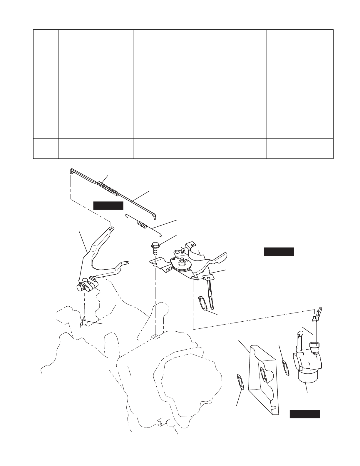
Step Parts to remove Remarks and procedures Fasteners
Drain the engine oill Remove a drain plug (M14 x 12mm) located on both
sides of the case.
1
Drain the fuel Shut (OFF) the fuel strainer.
2
OIL GAUGE
Take care not to lose the gaskets.
To discharge oil quickly, remove the oil guage(M22).
*
Drain fuel from the carburetor drain.
14 mm spanner
+ or - screwdriver
GASKET
STEP 2
STEP 1
GASKET
DRAIN PLUG
Fig.5-2
OFF
FUEL STRAINER
Fig.5-3
-
13
-

Step Parts to remove Remarks and procedures Fasteners
PAPER ELEMENT
URETHAN FOAM
URETHANE ELEMENT
TYPE
DUAL ELEMENT TYPE
AIR CLEANER
COVER
URETHAN FOAM
AIR CLEANER
COVER
AIR CLEANER BASE
M6 FLANGE NUT : 2 pcs.
M6 x 16 FLANGE BOLT : 1 pc.
GASKET
BREATHER PIPE
Air cleaner cover Remove the air cleaner cover and element.
-
screwdriver
3
Air cleaner Remove the air cleaner while pulling the breather pipe
away from the rocker cover.
4
STEP 3
STEP 3
10 mm box spanner
M6 nut : 2 pcs.
M6 x 16 : 1 pc.
STEP 4
Fig.5-4
-
14
-

Step Parts to remove Remarks and procedures Fasteners
FUEL STRAINER
M6 x 12 BOLT : 1 pc.
Muffler and Muffler cover (1) Remove the muffler cover from the muffler.
(2) Remove the muffler from the cylinder head. Take
care not to lose the gasket.
Take care not to cut your hand with the muffler
*
5
Fuel tank (1)
6
gasket.
Seal the exhaust port with adhesive tape or plug
*
it with cloth to prevent nuts and other objects from
falling inside.
Remove the fuel tank mounting nuts and bolts from
the crankcase.
(2)
Disconnect fuel hose from the strainer to carburetor
side. Remove the bolt for fuel strainer.
(3)Remove the fuel tank from the crankcase.
12 mm box spanner
10 mm box spanner or
spanner
M6 x 8 mm : 4 pcs.
M8 nut : 2 pcs.
M8 x 12 mm : 1 pc.
12 mm box spanner
12 mm spanner
M8 nut : 2 pcs.
M8 x 25 mm : 2 pcs.
- screwdriver
10 mm box spanner
M6 x 12 mm : 1 pc.
Fig.5-6
STEP 6
FUEL TANK
M8 NUT
: 2 pcs.
MUFFLER COVER
M6 x 8 FLANGE BOLT : 4 pcs.
STEP 5
M8 NUT : 2 pcs.
MUFFLER
M8 x 12
BOLT : 1 pc.
A
GASKET(It has two faces)
A
M8 x 25
BOLT : 2 pcs.
-
15
Seal the exhaust port with adhesive
tape or plug it with cloth.
Fig.5-5
-

Step Parts to remove Remarks and procedures Fasteners
7
8
9
10
Stop switch Disconnect the wire and remove the stop switch from
the blower housing.
Recoil starter Remove the recoil starter from the blower housing. 10 mm box spanner
Blower housing
Recoil bracket
Baffle 2
M4 x 12 SCREW and WASHER : 2 pcs.
(1)
Remove the blower housing (synthetic resin) from
the crankcase.
(2) Remove the recoil bracket from the crankcase.
Remove the baffle 2 ( synthetic resin ) from the
crankcase.
M6 x 14 BOLT : 4 pcs.
STEP 7
+ screwdriver
M4 x 12 mm : 2 pcs.
M6 x 14 mm : 4 pcs.
10 mm box spanner
M6 x 16 mm : 5 pcs.
M6 nut : 4 pcs.
10 mm box spanner
M6 x 12 mm : 3 pcs.
STEP 8
STOP SWITCH
M6 FLANGE NUT : 4 pcs.
M6 x 16 BOLT : 5 pcs.
M6 x 12 BOLT : 3 pcs.
STEP 10
BAFFLE 2
Fig.5-7
BLOWER HOUSING
RECOIL BRACKET
RECOIL STARTER
STEP 9
-
16
-
Step Parts to remove Remarks and procedures Fasteners
GOVERNOR SPRING
M6 x 12 BOLT : 1 pc. (temporary screw)
ROD SPRING
GOVERNOR ROD
SPEED CONTROL LEVER and BRACKET
GASKET
CHOKE LEVER
GASKET
CARBURETOR
GASKET
INSULATOR
GOVERNOR LEVER
GOVERNOR
SHAFT
STEP 11
STEP 12
STEP 13
11
12
13
Speed control lever and
Bracket
Governor system (1) Loosen the bolt and remove the governor lever
Carburetor, Insulator Remove the carburetor from the cylinder head.
Remove the speed control lever and bracket from the
cylinder head.
Release the bolt temporarily.
Slide to dismount the speed control lever and bracket
from the cylinder head and the choke lever of the
carburetor.
from the governor shaft. There is no need to
remove the bolt.
(2) Remove the governor spring.
(3) Remove the governor rod and the rod spring from
the carburetor.
Remove the insulator.
10 mm box spanner
M6 x 12 mm : 1 pc.
10 mm box spanner or
spanner
M6 x 25 mm : 1 pc.
-
17
Fig.5-8
-
Step Parts to remove Remarks and procedures Fasteners
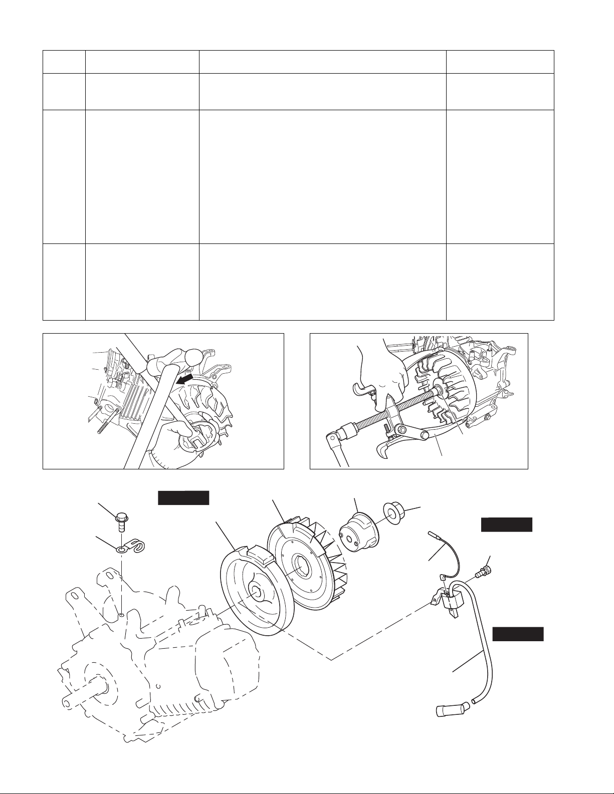
FLYWHEEL PULLER
ATTACH NUT
TEMPORARILY
14
15
16
Ignition coil Remove the spark plug cap from the spark plug and
remove the ignition coil from the crankcase.
Starting pulley
Cooling Blower
Flywheel Remove the flywheel from the crankshaft. Leave the nut
Remove the starting pulley and cooling Blower from the
flywheel.Fit a box wrench or a socket wrench on the
flywheel nut and loosen the nut by knocking the wrench
sharply with a hammer. (See Fig. 5-10)
NOTE:
1. Do not insert a screwdriver or other object between the
flywheel blades which is a synthetic resin, otherwise the
risk of damaging the blades might be occurred.
2. Knock the wrench with a hammer in a counter clockwise
direction.
temporarily to prevent the flywheel from dropping out. Fit
the flywheel puller as shown in Figure 5-11 and remove
the flywheel from the crankshaft by rotating the bolt at the
center in a clockwise direction.
(Knock the center bolt with a hammer sometimes)
10 mm box spanner
M6 x 25 mm:2 pcs.
24 mm box spanner or
socket wrench
M18 nut
Flywheel puller
M6 x 8 BOLT : 1 pc.
CLAMP
Fig.5-10 Fig.5-11
STEP 16
FLYWHEEL
COOLING BLOWER
Fig.5-9
-
18
STARTING PULLEY
M18 NUT : 1 pc.
WIRE : 1 pc.
IGNITION COIL
-
STEP 15
M6 x 25 BOLT and
WASHER : 2 pcs.
STEP 14

Step Parts to remove Remarks and procedures Fasteners
[MODEL WITH
ELECTRIC STARTER TYPE]
Control box,
Diode rectifier,
Magnetic switch
Electric starter (option)
17
[MODEL WITHOUT
ELECTRIC STARTER TYPE]
Baffle 1 (Case)
(1) Disconnect the grounding cable from battery.
(2) Disconnect the wire leading from the key
switch“ST” terminal to the magnetic switch.
(3) Disconnect the wire that connects the positive
terminal of the battery to the magnetic switch.
(4) Remove the electric starter.
Remove the Baffle 1 from the crankcase.
12 mm box spanner
M8 nuts
12 mm box spanner
M8 x 12 mm : 1 pc.
MODEL WITH ELECTRIC
STARTER TYPE (OPTION)
M8 x 28
BOLT : 2 pcs.
M8 NUT
ELECTRIC
STARTER
STEP 17
MODEL WITHOUT
ELECTRIC STARTER TYPE
BAFFLE 1
(CASE)
M8 x 12
BOLT : 1 pc.
STEP 17
Fig.5-12
-
19
-

Step Parts to remove Remarks and procedures Fasteners
[MODEL WITH
CHARGE COIL TYPE]
Wire clamp
18
Disconnect the wire clamp.
NOTE:
Disconnect the wire clamp in this step, also an engine
which has both of the charge coil and the oil sensor.
However, please make sure to not damaged (cut off)
the oil sensor wire after disassembly procedure.
10 mm box spanner
M6 x 10 mm : 1 pc.
19
Charge coil
Spark plug Remove the spark plug from the cylinder head. 21 mm plug wrench
Remove the charge coil.
WIRE CLAMP
CHARGE COIL
M6 x 10 TAPPING BOLT : 1 pc.
STEP 18
A
15W
40W
200W
+ screwdriver
BOLTCHARGE COI L Q’ty
M6 x 20L
M6 x 25L
M6 x 20L
2
2
4
STEP 19
SPARK PLUG
15W
CHARGE COIL CHARGE COIL
CHARGE COIL
200W40W
VIEW A
Fig.5-13
-
20
-

Step Parts to remove Remarks and procedures Fasteners
Punch marks
The position of compression top dead center
20
21
Rocker cover (1) Remove the rocker cover from the cylinder head.
(2) Remove the gasket (rocker cover).
Rocker arm Remove the pin (rocker arm) and the rocker arm from
the cylinder head at the compression top dead center.
(See Fig. 5-16)
ROCKER ARM
(EXHAUST VALVE SIDE)
PIN
(ROCKER ARM)
ROCKER ARM (INTAKE VALVE SIDE)
10 mm box spanner
M6 x 12mm : 4 pcs.
Fig.5-15
STEP 21
ROCKER ARM
(INTAKE VALVE SIDE)
GASKET(ROCKER COVER)
A
Fig.5-16
ROCKER ARM
(EXHAUST VALVE SIDE)
PIN
(ROCKER ARM)
VIEW A
Fig.5-14
-
21
STEP 20
ROCKER COVER
M6 x 12 BOLT : 4 pcs.
-

Step Parts to remove Remarks and procedures Fasteners
22
Main bearing cover Remove the flange bolts of main bearing cover from
the crankcase.
Remove the main bearing cover while tapping gently
around the cover using a plastic hammer or similar
tool. (See Fig. 5-18)
Be careful not to damage the oil gauge or oil seal or
not to lose the pipe knocks.
12 mm box spanner
M8 x 38mm : 8 pcs.
Fig.5-18
M8 x 38 BOLT : 8 pcs.
STEP 22
PIPE KNOCK
MAIN BEARING COVER
Fig.5-17
-
22
-

TENSIONER
SPRING
(TENSIONER)
CHAIN
PIN
(TENSIONER)
PIN
(CAMSHAFT)
CAMSHAFT
M6 x 12 BOLT : 1 pc.
Bolt used to prevent the
pin (camshaft) from coming out
CHAIN
STEP 23
STEP 23
Step Parts to remove Remarks and procedures Fasteners
CHAIN
CAMSHAFT
PIN (TENSIONER)
PIN (CAMSHAFT)
M6 x 12 BOLT : 1 pc.
Bolt used to prevent the
pin (camshaft) from coming out
23
Tensioner, Camshaft (1) Remove the tensioner. (See Fig. 5-20)
Do not lose the pin (tensioner).
(2) Remove the retaining bolt of pin (camshaft) from
the cylinder head. (See Fig. 5-21)
(3) Remove the pin (camshaft), taking care not to
scratch the O-ring.
(4) Remove the chain from the camshaft sprocket and
then take out the camshaft. (See Fig. 5-22)
(5) Remove the chain from the crankshaft.
Fig.5-20
Fig.5-21
M10 box spanner or
spanner
M6 x 12mm : 1 pc.
Pliers
Fig.5-22
-
Fig.5-19
23
-
 Loading...