

Page 1
2003 LEGACY SERVICE MANUAL QUICK REFERENCE INDEX
BODY SECTION
This service manual ha s bee n pre pared
to provide SUBARU service personnel
with the necessary information and data
for the correct maintenan ce and repair
of SUBARU vehicles.
This manual includes the procedures
for maintenance, disassembling, reassembling, insp ection and adjustmen t of
components and diagnostics for guidance of experienced mechanics.
Please peruse and utilize this manual
fully to ensure compl ete repair work for
satisfying our customers by keeping
their vehicle in optimum condition.
When replacement of parts during
repair work is needed, be sure to use
SUBARU genuine parts.
HVAC SYSTEM
(HEATER, VENTILATOR AND A/C)
HVAC SYSTEM (DIAGNOSTICS) AC
AIRBAG SYSTEM AB
AIRBAG SYSTEM (DIAGNOSTICS) AB
SEAT BELT SYSTEM SB
LIGHTING SYSTEM LI
WIPER AND WASHER SYSTEMS WW
ENTERTAINMENT ET
COMMUNICATION SYSTEM COM
GLASS/WINDOWS/MIRRORS GW
AC
All information, illustration and specifications contained in this manual are
based on the lates t product informat ion
available at the time of publication
approval.
FUJI HEAVY INDUSTRIES LTD. G2300GE7
BODY STRUCTURE BS
INSTRUMENTATION/DRIVER INFO IDI
SEATS SE
SECURITY AND LOCKS SL
SUNROOF/T-TOP/CONVERTIBLE TOP
(SUNROOF)
EXTERIOR/INTERIOR TRIM EI
EXTERIOR BODY PANELS EB
EXTERIOR/INTERIOR TRIM EI
SR
Page 2
2003 LEGACY SERVICE MANUAL QUICK REFERENCE INDEX
BODY SECTION
CRUISE CONTROL SYSTEM CC
CRUISE CONTROL SYSTEM
(DIAGNOSTICS)
IMMOBILIZER (DIAGNOSTICS) IM
CC
G2300GE7
Page 3

AIRBAG SYSTEM (DIAGNOSTICS)
1. Basic Diagnostic Procedure........................................................................2
2. Check Lis t fo r In terview........................................ .. .. ............. .. ... ............. .. ..3
3. General Description....................................................................................4
4. Electrical Components Location................................................................15
5. Airbag Connector......................................................................................17
6. Airbag Warning Light Illumination Pattern.................................................19
7. Read Diagnostic Trouble Code (DTC)......................................................20
8. Inspection Mode........................................................................................21
9. Clear Memo ry Mode ... ............. .. .. ............. ... .. ............. .. ... ............. .. .. .........22
10. Airbag Warning Light Failure.....................................................................24
11. List of Diagnostic Trouble Code (DTC)....................................... ..............28
12. Diagnostic Chart with Diagnostic Trouble Code (DTC).............................30
AB
Page
Page 4
BASIC DIAGNOSTIC PROCEDURE
AIRBAG SYSTEM (DIAGNOSTICS)
1. Basic Diagnostic Procedure
A: PROCEDURE
Step Value Yes No
1 Read DTC.
<Ref. to AB-20, Read Diagnostic Trouble Code
(DTC).>
2 Read DTC.
<Ref. to AB-20, Read Diagnostic Trouble Code
(DTC).>
3 P erfor m the diagn osi s.
1) Judge the possible cause from “List of
Diagnostic Trouble Code (DTC)” <Ref. to
AB-28, List of Diagnostic Trouble Code
(DTC).> .
2) Inspect using “Diagnostic Chart with Diagnostic Trouble Code (DTC)”.
3) Repair the cause of the trouble.
4) Perform the clear memory mode. <Ref. to
AB-22, Clear Memory Mode.>
5) Perform the inspection mode. <Ref. to AB21, Inspection Mode.>
6) Read DTC.
Is the normal code being
detected?
Is the DTC being detected? Go to step 3. Go to “Airbag
Is the DTC being detected? Perform the proce-
Finish the diagnosis.
dure 1) to 5) in
step 3.
Go to step 2.
Warning Light Failure”.<Ref. to AB24, Airbag Warning Light Failure.>
Finish the diagnosis.
AB-2
Page 5

CHECK LIST FOR INTERVIEW
2. Check List for Interview
A: CHECK
Customer's N ame Inspector's Name
Date Vehicle Brought In / / Registration No.
AIRBAG SYSTEM (DIAGNOSTICS)
Odometer Reading
Date Problem Occurred / / Registration Year / /
Weather ❏ Fine ❏ Cloudy ❏ Rainy ❏ Snowy ❏ Other:
Temperature °C (°F)
Road Condition ❏ Level road ❏ Uphil ❏ Downhill ❏ Rough road ❏ Others:
Vehicle Operation
❏ Driving (❏ Constant Speed ❏ Acceleration ❏ Deceleration
km
Vin No.
Miles
❏ Starting ❏ Idling
❏ Steering wheel turn ❏ Other: )
Details of Problem
Check Airbag Warning Light ❏ Remains ON ❏ Remains OFF
Check DTC ❏ Normal Code ❏ Trouble Code: (Code: )
AB-3
Page 6
AIRBAG SYSTEM (DIAGNOSTICS)
GENERAL DESCRIPTION
3. General Description
A: CAUTION
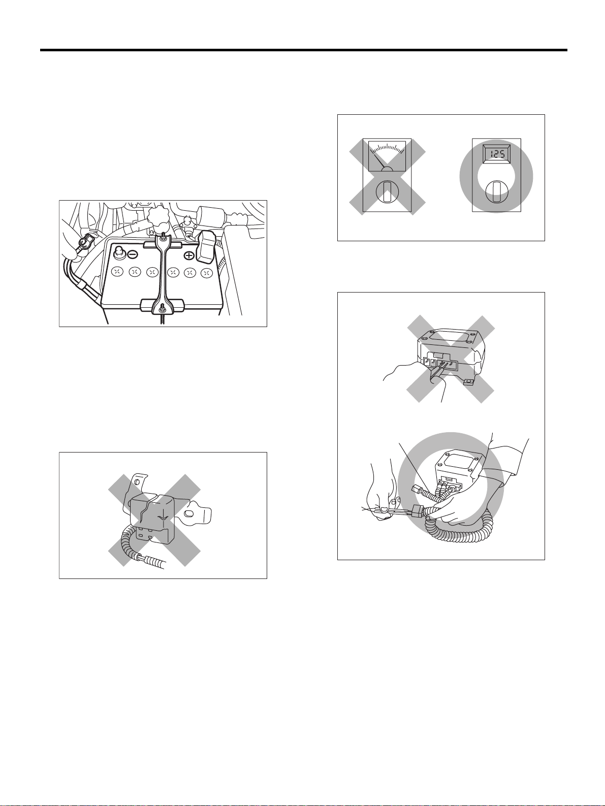
• When servicing a vehicle, be sure to turn the ignition switch OFF, disconnect the ground cable
from the battery, and wai t for more than 20 seconds
before starting work.
• The airbag system is fitted with a backup power
source. If the airbag system is serviced within 20
seconds after the ground cable is disconnected, it
may inflate.
AB-00002
• If the airbag warning light illuminates, repair the
vehicle immediately. Airbag or prete nsioner may inflate incorrectly, or not inflate in collision.
• If sensors, airbag module, airbag contr ol module
pretensioner, and harness are deformed or damaged, replace them with new genuine parts.
• Do not use the airbag system and pretensioners
on other vehicles. When replaci ng parts, be sure to
replace them with new parts.
• When checking the system, be sure to use a digital circuit tester.
Use of an analog circuit tester may cause the airbag to activate erroneously.
AB-00121
• When checking, use a test harness. Do not directly apply the tester probe to any connecto r terminal of the airbag.
( 1 )
AB-00120
AB-00122
(1) Test harness
AB-4
Page 7
GENERAL DESCRIPTION
AIRBAG SYSTEM (DIAGNOSTICS)
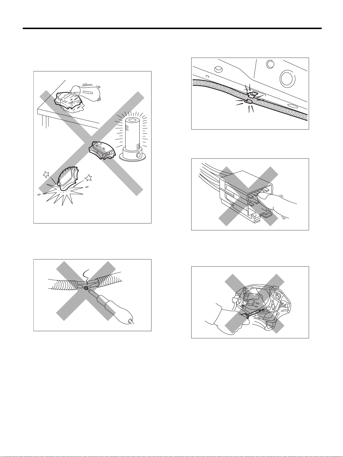
• Do not drop the airbag modulator parts, subject
them to high temperature over 93°C (199°F), or let
water, oil, or grease get on t hem; other wis e, the i nternal parts may be damaged and reliability greatly
lowered.
• Install the wire harness securely with the specified clips to avoid interference or tangled up with
other parts.
AB-00125
• Do not allow water or oil to come in contact with
the connector terminals. Do not touch the connector terminals.
AB-00123
• If any damage, opening or rust is found on the
airbag system wire harness, do not attempt to repair using soldering equipment. Be sure to replace
the faulty harness with a new genuine part.
AB-00124
AB-00126
• The airbag module (driver, passenger, and side,
pretensioner) must not be disassembled.
• The airbag module cannot be used again once
inflated.
AB-00127
AB-5
Page 8
AIRBAG SYSTEM (DIAGNOSTICS)
GENERAL DESCRIPTION
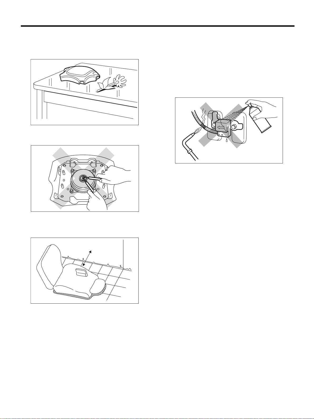
• After removal, keep the airbag module with the
pad facing upward on a dry, clean, and flat surface
away from heat and light sources, and moisture
and dust.
AB-00056
• Do not check continuity of the airbag module
(driver, passenger, and side, pretensioner).
• When painting or performing sheet metal work
on the front part of the vehicle, including the front
wheel apron, front fender, and front side frame, remove the front sub sensors and wi re harnes s of the
airbag system.
• When painting or performing sheet metal work
on the side of the vehicle, including the side sill,
center pillar, and front and rear doors, remove the
side airbag sensors and wire harness of the airbag
system.
AB-00129
• Do not discard undeployed airbag modules.
They could easily cause a serious accident if accidentally deployed.
• Do not damage the airbag module or drop it.
AB-00006
• The removed front seat with the airbag module
must be kept at least 200 mm (8 in) away from walls
and other objects.
( 1 )
AB-00128
(1) More than 200 mm (8 in)
AB-6
Page 9
GENERAL DESCRIPTION
AIRBAG SYSTEM (DIAGNOSTICS)
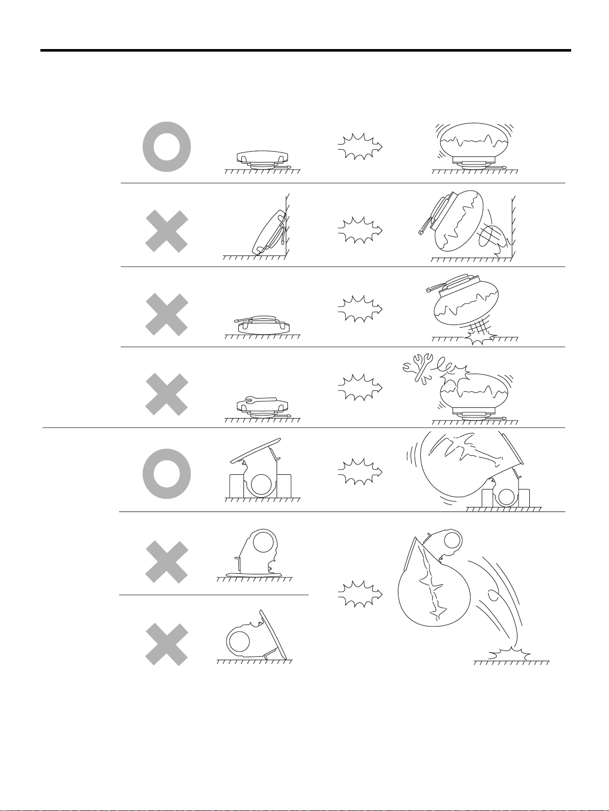
• When storing a removed airbag module, do not place any objects on it or pile airbag modules on top of
each other. If the airbag inflates for some reas on when it is placed with its pad side faci ng downward or under
any object, a serious accident may result.
( 1 )
( 2 )
(1) Driver side (2) Passenger side
AB-00130
AB-7
Page 10

GENERAL DESCRIPTION
AIRBAG SYSTEM (DIAGNOSTICS)
B: INSPECTION
Before diagnosing, check the following items that
might be related to the engine problem:
1. BATTERY
Measure battery voltage and specific gravity of
electrolyte.
Standard voltage: 12 V
Specific gravity: Above 1.260
AB-8
Page 11
GENERAL DESCRIPTION
AIRBAG SYSTEM (DIAGNOSTICS)
C: PREPARATION TOOL
CAUTION:
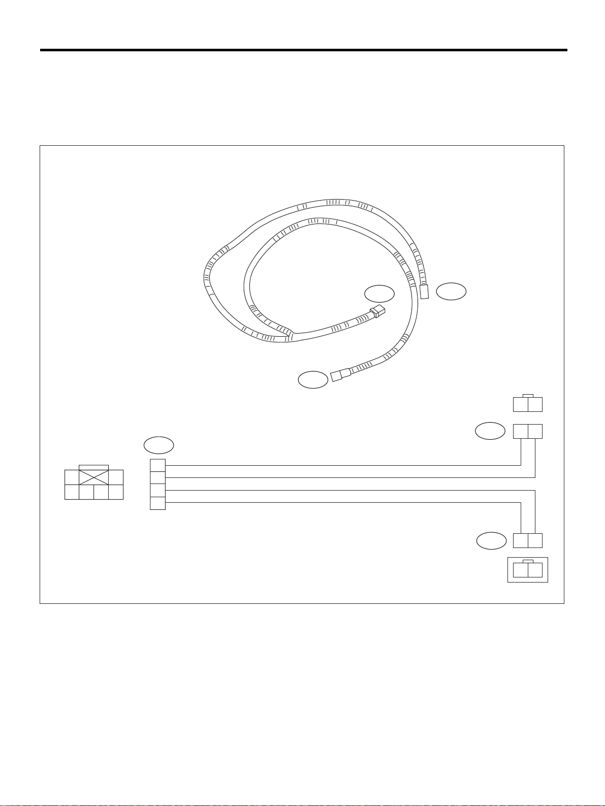
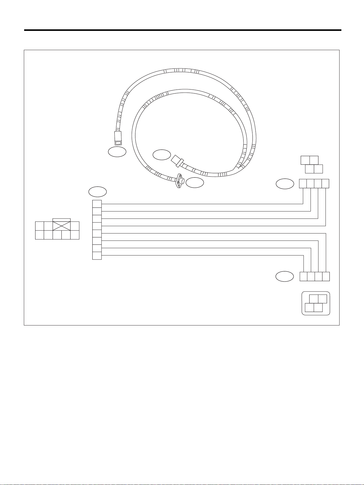
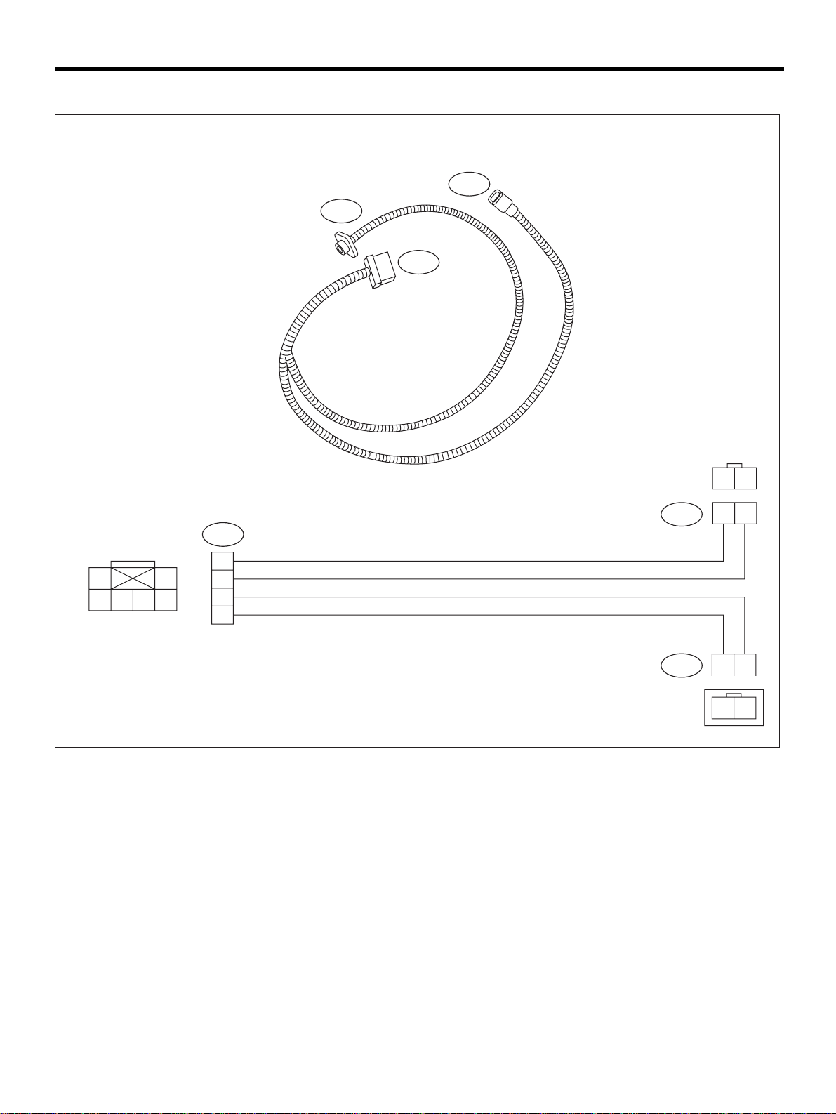
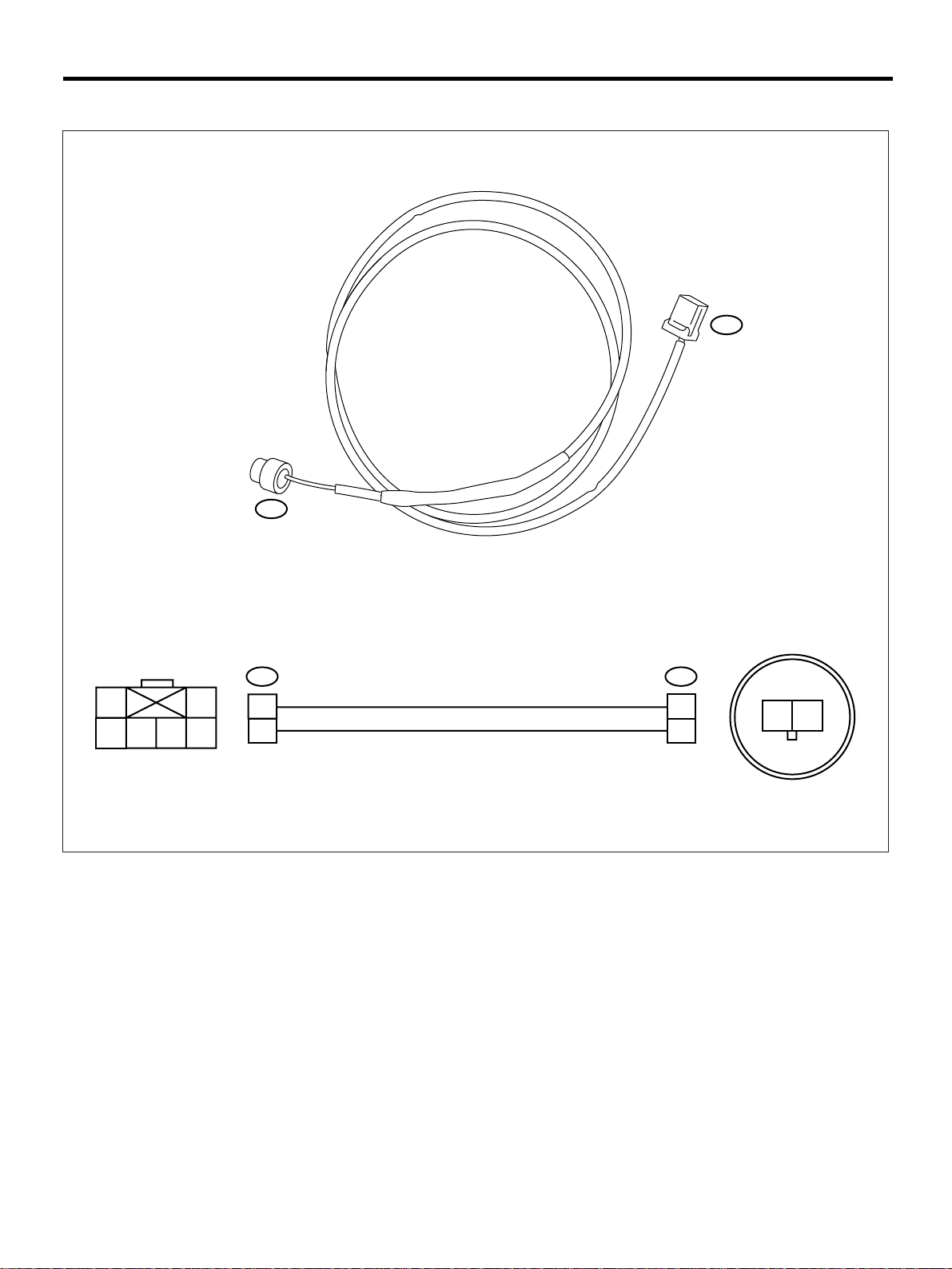
Be sure to use specified test harness F, G, H, K and I or I2 when measuring voltage, resistance, etc.
of AIRBAG system component parts.
1. TEST HARNESS F
PN 98299FC010
12
6
45
3
3F
5
6
3
4
1F
3F
2F
2F
1F
2
1
2
1
2
1
1
2
AB-9
AB-00058
Page 12
AIRBAG SYSTEM (DIAGNOSTICS)
2. TEST HARNESS G
PN 98299FC020
GENERAL DESCRIPTION
1
23
56
4
7
8
3G
6
7
3
8
4
5
1
2
2G
3G
1G
2G
1G
1
1
4
2
43
4
32
4321
21
3
AB-00059
AB-10
Page 13
3. TEST HARNESS H
PN 98299FA030
GENERAL DESCRIPTION
AIRBAG SYSTEM (DIAGNOSTICS)
2H
1H
3H
1
456
3
12
2H
3H
3
2
4
5
6
1H
12
12
12
AB-00060
AB-11
Page 14
AIRBAG SYSTEM (DIAGNOSTICS)
4. TEST HARNESS N
PN 98299SA000
1Q
GENERAL DESCRIPTION
2Q
1B 2B
2Q
1B
2B
1Q
1A
2A
1A 2A
AB-00064
AB-12
Page 15
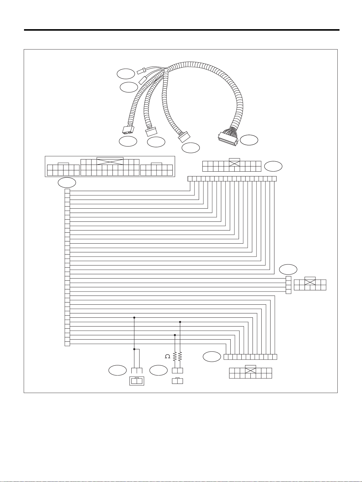
5. TEST HARNESS I2
PN 98299FC041
GENERAL DESCRIPTION
AIRBAG SYSTEM (DIAGNOSTICS)
5l
4l
123456
789
10 11 12
1l
32
27
21
38
7
41
45
42
46
1
5
2
6
9
10
12
47
49
50
52
19
29
20
28
40
39
31
30
17
16
14
25
23
13
26
22
3l
13 14 15 16 17 18
19 20 21 22 23 2425 26
33 34 35 36 37
30 31 32 38 39 40
27 28 29
6l
41 42 4344 45 46
47 48 4950 51 52
2l
2345
1
10 11 12 13 14 15 16 17 18 19 20
23456789
1
1l1l
6789
10111213141516171819
3l
20
6l
1
12 34
2
3
56 9
4
78
10
12
12
100
5l4l
12
12
AB-13
123456789
2l
12
3456
11 12 13 14
9
10
78
101112
AB-00282
Page 16
GENERAL DESCRIPTION
AIRBAG SYSTEM (DIAGNOSTICS)
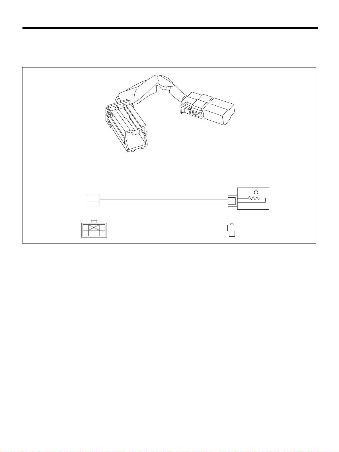
6. AIRBAG RESISTOR
The airbag resistor is used during diagnostics. The airbag resistor has the same resistance as the airbag
module and thus provid es safet y when used instea d of the ai rb ag module. It al so makes it pos sible to fini sh,
diagnostics in less time.
PN 98299PA040
Y
3
R
4
12
3654
Y
2
R
1
1
2
3
AB-00067
AB-14
Page 17
ELECTRICAL COMPONENTS LOCATION
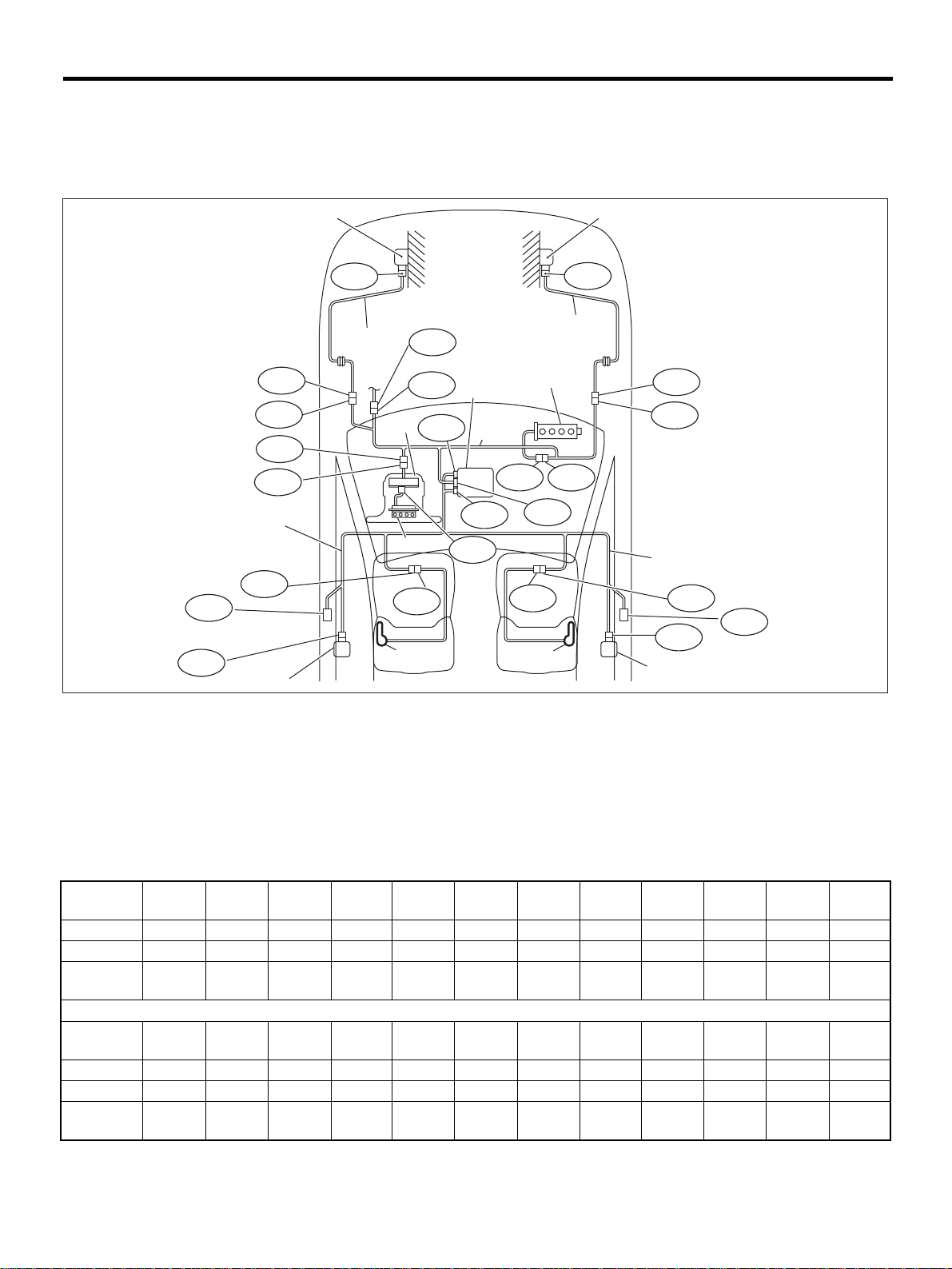
4. Electrical Components Location
A: LOCATION
1. LHD MODEL
AIRBAG SYSTEM (DIAGNOSTICS)
AB21
( b )
AB23
AB12
AB11
AB8
AB3
(10)
AB19
(12)
( 1 )
AB13
( 3 )
( a )
( 7 )
( 9 )
AB20
(14)
B31
AB1
AB17
( 5 )
( 8 )
AB18
AB7
AB10
AB6
AB25
(15)
( 6 )
AB16
( 4 )
AB9
( 2 )
AB15
AB14
(11)
AB28
(13)
AB24
AB26
( c )
AB-00347
(1) Front sub sensor (LH) (7) Roll connector (13) Side airbag sensor (RH)
(2) Front sub sensor (RH) (8) Airbag main harness (14) Side airbag inflator (LH)
(3) Front sub sensor harness (LH) (9) Inflator (Driver) (15) Side airbag inflator (RH)
(4) Front sub sensor harness (RH) (10) Side airbag harness (LH) (a) To body harness
(5) Airbag control module with safety
sensor and electric sensor
(6) Inflator (Passenger)
Connec-
tor No.
Pole12222822222222
Color Yellow Yellow Yellow Yellow Black Yellow Yellow Yellow Blue Blue Yellow Blue
Male/
Female
Connec-
tor No.
Pole22121222242224
Color Blue Yellow Yellow Yellow Yellow Yellow Yellow Yellow Yellow Yellow Yellow Yellow
Male/
Female
(AB1) (AB2) (AB3) (AB6) (AB7) (AB8) (AB9) (AB10) (AB11) (AB12) (AB13) (AB14)
Male Male Male Female Female Female Female Male Male Female Female Male
(AB15) (AB16) (AB17) (AB18) (AB19) (AB20) (AB21) (AB23) (AB24) (AB25) (AB26) (AB28)
Female Female Female Female Female Male Female Female Female Male Female Female
(11) Side airbag harness (RH) (b) To seal belt pretensioner (LH)
(12) Side airbag sensor (LH) (c) To seal belt pretensioner (RH)
AB-15
Page 18
ELECTRICAL COMPONENTS LOCATION
AIRBAG SYSTEM (DIAGNOSTICS)
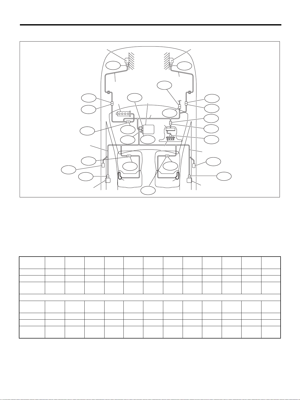
2. RHD MODEL
AB21
( b )
AB12
AB11
AB9
(10)
AB19
AB23
(12)
( 1 )
AB13
( 3 )
( 6 )
AB17
AB10
AB6
AB20
(14)
( 5 )
( 8 )
AB18
AB25
B31
AB1
( 7 )
( 9 )
AB24
(15)
AB16
( 4 )
( a )
( 2 )
AB15
AB14
AB8
AB3
AB7
(11)
AB26
( c )
AB28
(13)
AB-00348
(1) Front sub sensor (LH) (7) Roll connector (13) Side airbag sensor (RH)
(2) Front sub sensor (RH) (8) Airbag main harness (14) Side airbag inflator (LH)
(3) Front sub sensor harness (LH) (9) Inflator (Driver) (15) Side airbag inflator (RH)
(4) Front sub sensor harness (RH) (10) Side airbag harness (LH) (a) To body harness
(5) Airbag control module with safety
sensor and electric sensor
(6) Inflator (Passenger)
Connec-
tor No.
Pole12222822222222
Color Yellow Yellow Yellow Yellow Black Yellow Yellow Yellow Blue Blue Yellow Blue
Male/
Female
Connec-
tor No.
Pole22121222242224
Color Blue Yellow Yellow Yellow Yellow Yellow Yellow Yellow Yellow Yellow Yellow Yellow
Male/
Female
(AB1) (AB2) (AB3) (AB6) (AB7) (AB8) (AB9) (AB10) (AB11) (AB12) (AB13) (AB14)
Male Male Male Female Female Female Female Male Male Female Female Male
(AB15) (AB16) (AB17) (AB18) (AB19) (AB20) (AB21) (AB23) (AB24) (AB25) (AB26) (AB28)
Female Female Female Female Female Male Female Female Female Male Female Female
(11) Side airbag harness (RH) (b) To seal belt pretensioner (LH)
(12) Side airbag sensor (LH) (c) To seal belt pretensioner (RH)
AB-16
Page 19
AIRBAG CONNECTOR
AIRBAG SYSTEM (DIAGNOSTICS)
5. Airbag Connector
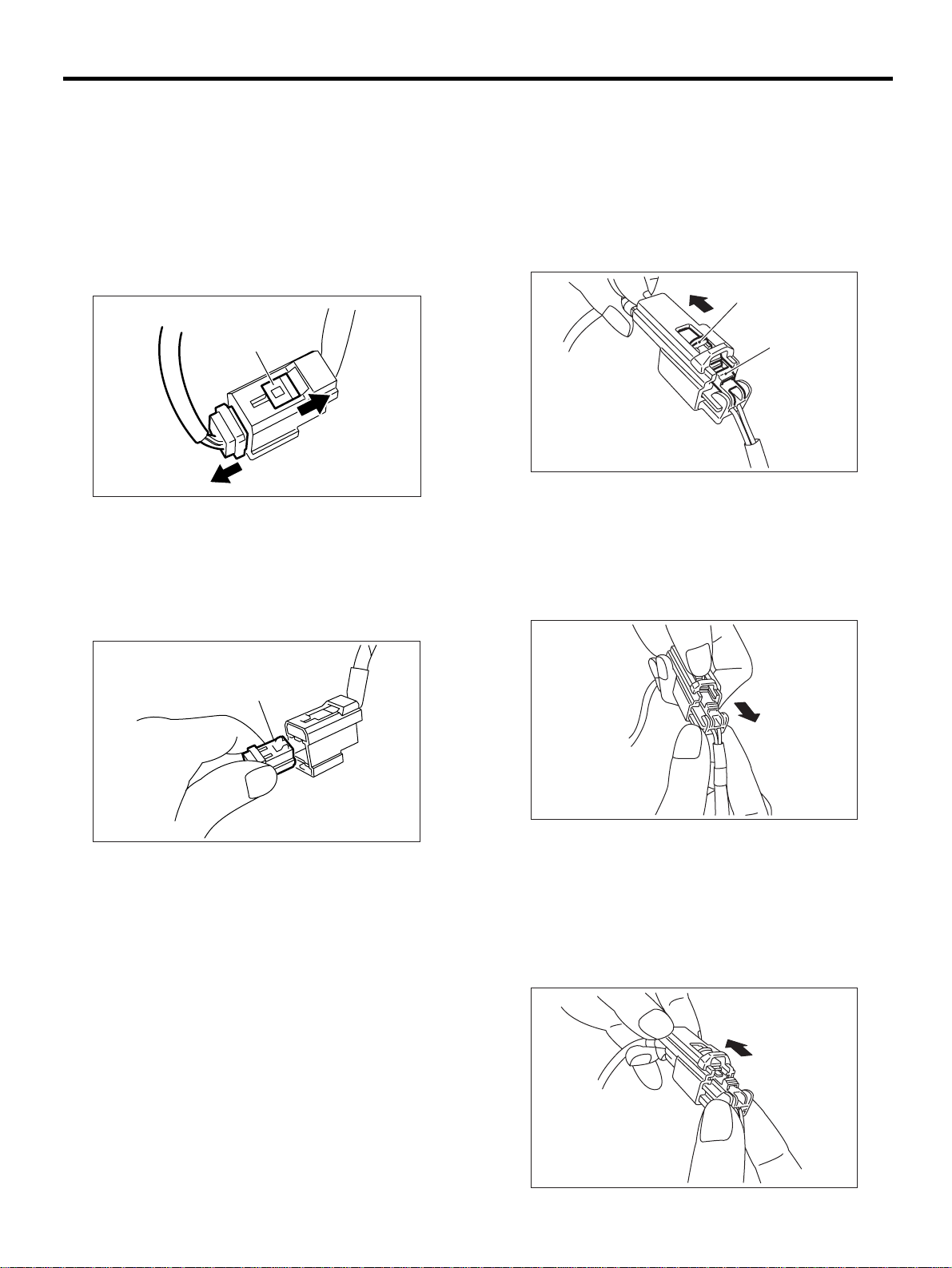
A: OPERATION
1. POWER SUPPLY
1) How to disconnect:
(1) Move the slide lock (A) in the direction of the
arrow.
(2) Pull the female connector in the direction of
the arrow with slide lock (A) moved.
( A )
AB-00015
CAUTION:
When pulling, be sure to hold onto the conector
and not the wire.
2) How to connect:
Holding the connector (A), and push it in carefully
until a connecting sound is head.
2. DRIVER'S AIRBAG, PASSENGER’S AIRBAG, SIDE AIRBAG, FRONT SUB SENSOR
HARNESS TO AIRBAG MAIN HARNESS
AND PRETENSIONER
1) How to disconnect:
(1) Push lock arm (A).
(2) With lock arm (A) pushed in, move slide lock
(B) in the direction of the arrow.
( B )
( A )
AB-00017
(3) With slide lock (B) pulled, remove lock arm
(A) to its original position, and then pul l in t he direction of the arrow and separate t he connector.
CAUTION:
When pulling, be sure to hold onto the connector and not the wire.
( A )
AB-00016
CAUTION:
Be sure to insert the connect or in until it locks.
Then pull on it gently to make sure that it is
locked.
AB-00018
2) How to connect:
Holding the connector, and push it in carefully until
a connecting sound is heard.
CAUTION:
Be sure to insert the connector in until it locks.
Then pull on it gently to make sure that it is
locked.
AB-17
AB-00019
Page 20
AIRBAG SYSTEM (DIAGNOSTICS)
AIRBAG CONNECTOR
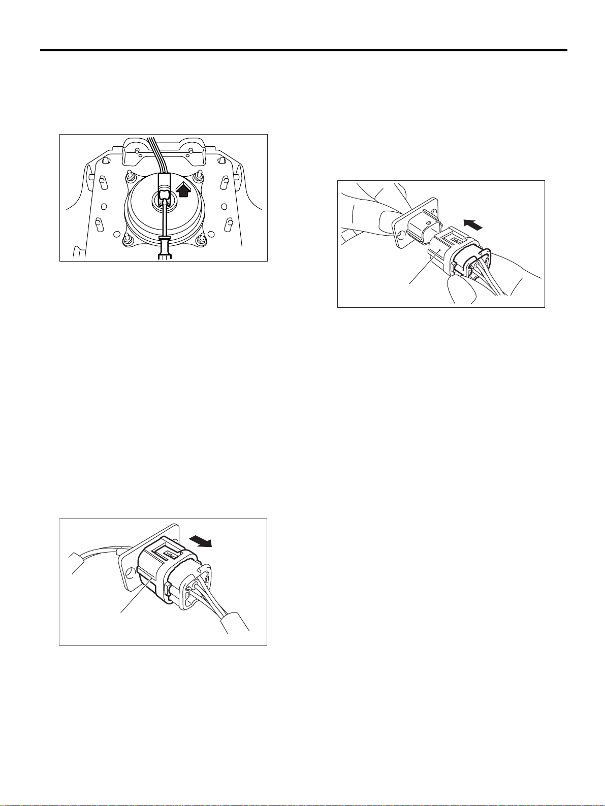
3. DRIVER'S AIRBAG (ROLL CONNECTOR
AND AIRBAG MODULE
1) How to disconnect:
(1) Using a flat tip screwdriver, pry the push
lock upward to unlock.
AB-00020
(2) Pull the connector to disconnect from driver’s side airbag module assembly.
2) How to connect:
Connect the connector in reverse order of disconnecting. At this time, be sure to insert the connector
in until connecting sound is heard.
CAUTION:
Be sure to insert the connect or in until it locks.
Then pull on it gently to make sure that it is
locked.
2) How to connect:
Holding the connector, and push it in carefully until
a connecting sound is heard.
CAUTION:
• Outer (A) moves back, and so do not put your
hand on the outer part.
• Be sure to insert the connector in until it
locks. Then pull on it gently t o make sure that it
is locked.
( A )
AB-00286
4. FRONT SUB-SENSOR, SIDE AIRBAG
SENSOR
1) How to disconnect:
(1) Holding outer part (A), pull it in the direction
of the arrow.
CAUTION:
When pulling, be sure to hold onto the connector and not the wire.
( A )
AB-00285
AB-18
Page 21
AIRBAG WARNING LIGHT ILLUMINATION PATTERN
6. Airbag Warning Light Illumi-
nation Pattern
A: INSPECTION
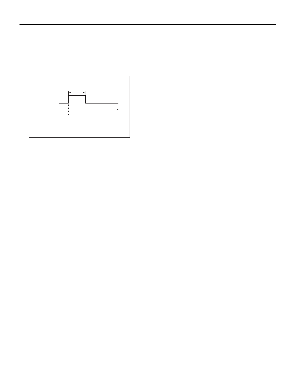
Keep the ignition switch ON, and confirm that the
airbag warning light remains off approximately 6
seconds after being turned on.
(2)
(1)
(1) Airbag warning light
(2) Approx. 6 seconds
(3) Ignition switch ON
ON
OFF
(3)
AB-00135
AIRBAG SYSTEM (DIAGNOSTICS)
AB-19
Page 22
READ DIAGNOSTIC TROUBLE CODE (DTC)
AIRBAG SYSTEM (DIAGNOSTICS)
7. Read Diagnostic Trouble
Code (DTC)
A: OPERATION
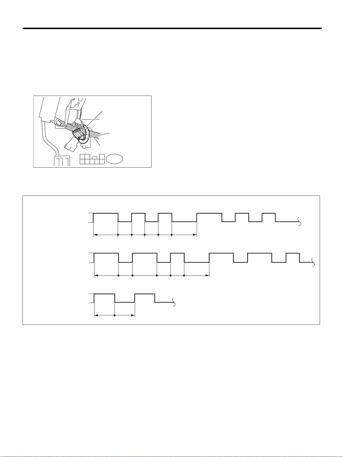
1) Turn the ignition switch ON.
2) Connect the diagnosis terminal to diagnos is con-
nector terminal No. 2 in the dri ver's seat lo wer co ver area.
( 1 )
( 2 )
1
4
(1) Diagnosis connector
(2) Diagnosis terminal
(1)
3
2
B82
765
8
AB-00290
3) Read DTC by identifying the way the air bag
warning light flashes.
The airbag warning light flashes a DTC corresponding to the faulty parts.
The long segment (1.2 sec on) indicates a “ten”,
and the short segment (0.3 sec on) indicates a
“one”.
NOTE:
•“List of Diagnostic Trouble Code (DTC)” <Ref. to
AB-28, List of Diagnostic Trouble Code (DTC).>
•“Airbag Warning Light Failure” <Ref. to AB-24,
Airbag Warning Light Failure.>
ON
(2)
(3)
(4)
(1) Example (3) Flashing code 21 (5) Sec.
(2) Flashing code 12 (4) Flashing normal code
OFF
ON
OFF
ON
OFF
10
1.2 0.3 0.3 0.3 0.3 1.2
10
1.2
0.6 0.6
11 10 11
10 1 10 10 1
0.3 1.2 0.3 0.3 1.2
(5)
(5)
(5)
4) Turn the ignition switch OFF, and disconnect the
diagnosis terminal from the diagnosis connector
terminal No. 2.
5) Wind tape around the diagnosis terminal and r e-
turn it to its original position.
AB-00137
AB-20
Page 23

INSPECTION MODE
8. Inspection Mode
A: OPERATION
Recreate the circumstance by referring to the conditions described in the checklist.
AIRBAG SYSTEM (DIAGNOSTICS)
AB-21
Page 24
CLEAR MEMORY MODE
AIRBAG SYSTEM (DIAGNOSTICS)
9. Clear Memory Mode
A: OPERATION
1) Turn the ignition switch ON.
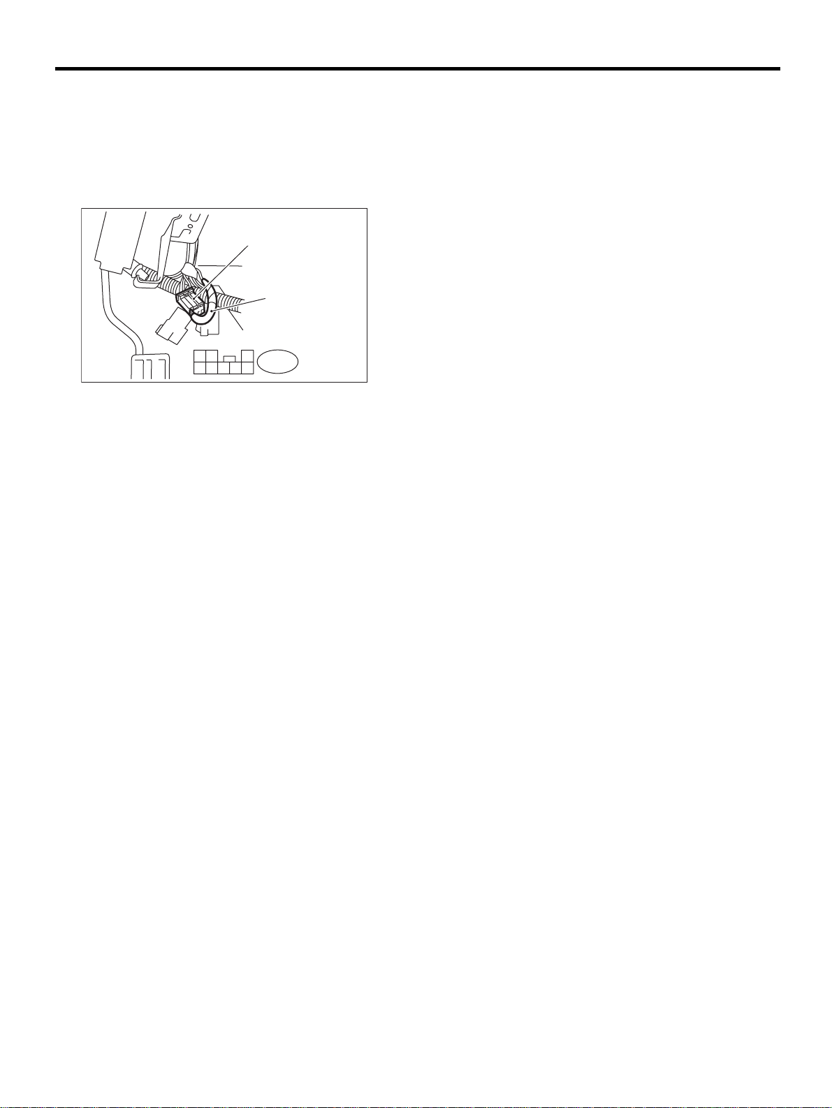
2) Connect the diagnosis terminal to diagnos is con-
nector terminal No. 2 in the dri ver's seat lo wer co ver area.
( 1 )
( 2 )
1
4
(1) Diagnosis connector
(2) DIAG. terminal
3
2
B82
765
8
AB-00290
3) While the warning light flashes, connect anot her
diagnosis terminal to diagnosis connector terminal
No. 3.
4) Once the memory is erased, the warning li ght re-
turns to the normal flash rate (0.6 sec on). The fai lure to recover the normal flash rate indicates that
trouble parts still remain. Having repaired such
parts, erase the memory again and confirm that the
normal flash rate has returned.
5) When the memory has been cleared, disconnec t
the diagnosis terminal from the diagnosis connector.
6) Wind tape around the diagnosis terminal and r e-
turn it to its original position.
AB-22
Page 25

MEMO:
CLEAR MEMORY MODE
AIRBAG SYSTEM (DIAGNOSTICS)
AB-23
Page 26
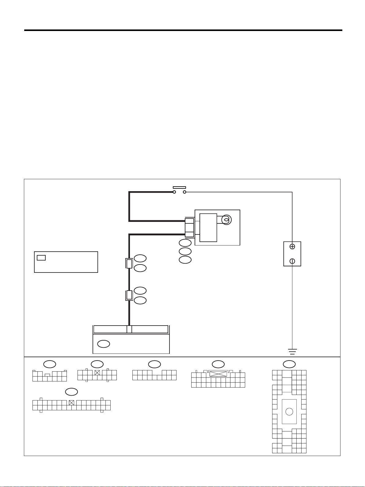
AIRBAG WARNING LIGHT FAILURE
AIRBAG SYSTEM (DIAGNOSTICS)
10.Airbag Warning Light Failure
A: AIRBAG WARNING LIGHT REMAINS ON.
DIAGNOSIS:
• Airbag warning light is faulty.
• Airbag control module to airbag warning light circuit is shorted or open.
• Grounding circuit is faulty .
• Airbag control module is faulty.
• (AB1) and (B31) are not connected properly.
• (AB6) is not connected properly to airbag control module.
CAUTION:
• Before diagnosing the airbag system, be sure to turn the ignition switch OFF, disconnect the
ground cable from the battery, and wait more than 20 seconds before starting to work.
• Before replacing the airbag module, roll connector, control module, and sensor, reconnect each
part and confirm that the warning light operates properly.
• When inspecting the airbag main harness, disconnect the airbag module connector of the driver
and passenger seats for safety reasons.
WIRING DIAGRAM:
IGNITION RELAY
: 4-CYLINDER
*
: 6-CYLINDER LHD
: 6-CYLINDER RHD : C11
B31
1 2
6 7 8 9
1 2 3 4 5 6 7 8 9
15 16 17 18 19 20 21 22 23 24 25 26 27 28 29 30
3
4 5
10 11 12
i10
: A5
: B8
1 2 3
7 8 9
10 11 12 13 14
AB6
i12
4 5 6
10 11 12 13 14
i1
I1
B36
B31
1
AB1
3
AIRBAG CONTROL MODULE
i11
1 2 3 4 5 6 7
8 9
10 11 12 13 14 15 16
C3
AIRBAG
CIRCUIT
*
A:
i10
B:
i11
C:
i12
1 2 3
7 8 9
18 19 20 21 22 23 24 25 26 27 28
AIRBAG
INDICATOR
LIGHT
AB6
10 11 12 13 14 15 16 17
4 5 6
A1 A2
B1 B2
C2
D1 D2
F1
G1
H1
I1
J1
K1
L2
L1
M1M2
N2
O1 O2
P1 P2
BATTERY
B36
A3
B3
C3
N3
O3
P3
A4 A5 A6
B4 B5 B6
C5 C6
C4
D4 D5 D6
E4 E5 E6E1 E2
F6
G6
H6
J6
K6
L4 L5 L6
M4M5 M6
N5 N6
N4
O4 O5 O6
P4 P5
P6
I6
AB-00356
AB-24
Page 27

AIRBAG WARNING LIGHT FAILURE
O
Step Value Yes No
1 CHECK POOR CONTACT IN CONNECTORS
(AB1) AND (B31).
1) Turn the ignition switch OFF, disconnect
the battery ground cable, and wait more
than 20 seconds.
2) Remove side sill cover. (Driver's side)
3) Confirm that firm contact is secured
between connectors (AB1) and (B31).
Is the poor contact in connect ors (AB1) and
(B31)?
2 CHECK POOR CONTACT.
Confirm that firm contact is secured between
the air bag control module and the connector
(AB6). <Ref. to AB-17, REMOVAL, Airbag
Control Module.>
Is the poor contact in connector (AB6)?
3 CHECK AIRBAG MAIN HARNESS.
1) Turn the ignition switch OFF, disconnect
the battery ground cable, and wait more
than 20 seconds.
2) Connect the connector (AB1) to (B31).
3) Disconnect connectors (AB3) and (AB8).
4) Pull out the two stopper pins and lower the
glove box and disconnect connectors
(AB10) and (AB9).
5) Disconnect the connector (AB6) from the
airbag control module, and connect the
connector (1I) in test harness I2. <Ref. to
AB-17, Airbag Control Module.>
6) Connect the battery ground cable and turn
the ignition switch ON.
7) Connect connectors (4I) and (5I) in test h arness I2.
TE:
N
After problem has been eliminated, disconnect
connectors (4I) and (5I).
Is the airbag warning light turned off?
4 CHECK AIRBAG MAIN HARNESS.
1) Connect the connector (AB1) to (B31).
2) Disconnect the connector (AB6) from the
airbag control module, and connect the
connector (1I) in test harness I2. <Ref. to
AB-17, Airbag Control Module.>
3) Measure the resista nce betw een connec tor
(2I) in test harness I2 and the chassis
ground.
Connector & terminal
(2I) No. 9 — Chassis ground:
(2I) No. 10 — Chassis ground:
Is the measured value less than the specified value?
AIRBAG SYSTEM (DIAGNOSTICS)
There is no poor contact. Go to step 2. Repair the body
harness or replace
airbag main harness. <Ref. to AB15, Main Harness.>
There is no poor contact. Go to step 3. Replace airbag
main harness.
<Ref. to AB-15,
Main Harness.> Or
replace the airbag
control module.
<Ref. to AB-17,
Airbag Control
Module.>
Airbag warning light turns
OFF.
10 Ω Replace the airbag
Go to step 4. Replace airbag
main harness.
<Ref. to AB-15,
Main Harness.> Or
replace combination meter printed
circuit. <Ref. to
IDI-14, Combination Meter Assembly.> Or repair the
body harness.
Replace airbag
control module.
<Ref. to AB-17,
Airbag Control
Module.>
main harness.
<Ref. to AB-15,
Main Harness.> Or
repair the body
harness.
AB-25
Page 28
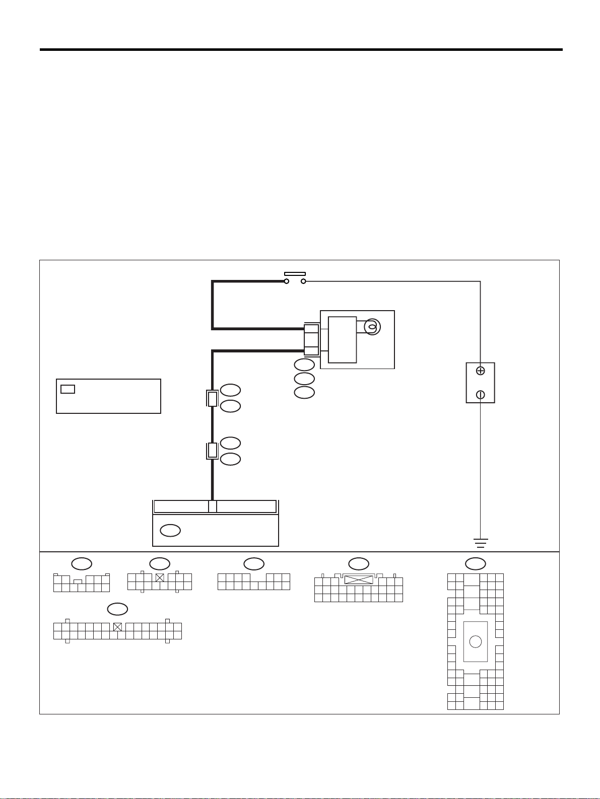
AIRBAG WARNING LIGHT FAILURE
AIRBAG SYSTEM (DIAGNOSTICS)
B: AIRBAG WARNING LIGHT REMAINS OFF.
DIAGNOSIS:
• Fuse No. 5 (in fuse box) is blown.
• Body harness circuit is open.
• Airbag warning light is faulty.
• Airbag main harness is faulty.
• Airbag control module is faulty.
CAUTION:
• Before diagnosing the airbag system, be sure to turn the ignition switch OFF, disconnect the
ground cable from the battery, and wait more than 20 seconds before starting to work.
• Before replacing the airbag module, roll connector, control module, and sensor, reconnect each
part and confirm that the warning light operates properly.
• When inspecting the airbag main harness, disconnect the airbag module connector of the driver
and passenger seats for safety reasons.
WIRING DIAGRAM:
IGNITION RELAY
: 4-CYLINDER
*
: 6-CYLINDER LHD
: 6-CYLINDER RHD : C11
B31
1 2
6 7 8 9
1 2 3 4 5 6 7 8 9
15 16 17 18 19 20 21 22 23 24 25 26 27 28 29 30
3
4 5
10 11 12
i10
: A5
: B8
1 2 3
7 8 9
10 11 12 13 14
AB6
i12
4 5 6
10 11 12 13 14
i1
I1
B36
B31
1
AB1
3
AIRBAG CONTROL MODULE
i11
1 2 3 4 5 6 7
8 9
10 11 12 13 14 15 16
C3
AIRBAG
CIRCUIT
*
A:
i10
B:
i11
C:
i12
1 2 3
7 8 9
18 19 20 21 22 23 24 25 26 27 28
AIRBAG
INDICATOR
LIGHT
AB6
10 11 12 13 14 15 16 17
4 5 6
A1 A2
B1 B2
C2
D1 D2
F1
G1
H1
I1
J1
K1
L2
L1
M1M2
N2
O1 O2
P1 P2
BATTERY
B36
A3
B3
C3
N3
O3
P3
A4 A5 A6
B4 B5 B6
C5 C6
C4
D4 D5 D6
E4 E5 E6E1 E2
F6
G6
H6
J6
K6
L4 L5 L6
M4M5 M6
N5 N6
N4
O4 O5 O6
P4 P5
P6
I6
AB-00356
AB-26
Page 29

AIRBAG WARNING LIGHT FAILURE
Step Value Yes No
1 CHECK COMBINATION METER.
Turn the ignition switch ON, and confirm that
warning lights equipped in the combination
meter are turned on.
Do warning lights not for the airbag turn on?
2 CHECK FUSE NO. 5 (IN MAIN FUSE BOX).
Remove fuse No. 5 and perform visual inspection.
Is fuse No. 5 (in main fuse box) blown?
3 CHECK AIRBAG WARNING LIGHT CIRCUIT
(IN COMBINATION METER).
1) Turn the ignition switch OFF, disconnect
the battery ground cable, and wait more
than 20 seconds.
2) Disconnect the connector (AB1) from
(B31).
3) Connect the battery ground cable and turn
the ignition switch ON.
Is the airbag warning light turned on?
4 CHECK AIRBAG MAIN HARNESS.
1) Turn the ignition switch OFF, disconnect
the battery ground cable, and wait more
than 20 seconds.
2) Connect the connector (AB1) to (B31).
3) Disconnect the connector (AB6) from the
airbag control module. <Ref. to AB-17, Airbag Control Module.>
4) Connect the battery ground cable and turn
the ignition switch ON.
Is the airbag warning light turned on?
AIRBAG SYSTEM (DIAGNOSTICS)
Warning lights not for the airbag turn ON.
Fuse No. 5 is not blown. Go to step 3. Replace fuse No.
Airbag warning light turns ON. Go to step 4. Replace airbag
Airbag warning light turns ON. Replace the airbag
Go to step 2. Repair combina-
tion meter power
supply. <Ref. to
IDI-4, Combination Meter System.>
5. If fuse No. 5
blows again, go to
step 3.
warning light bulb
or combination
meter printed circuit. <Ref. to IDI14, Combin ation
Meter Assembly.>
Or repair the body
harness.
Replace airbag
control module.
<Ref. to AB-17,
Airbag Control
Module.>
main harness.
<Ref. to AB-17,
Airbag Control
Module.>
AB-27
Page 30

LIST OF DIAGNOSTIC TROUBLE CODE (DTC)
AIRBAG SYSTEM (DIAGNOSTICS)
11.List of Diagnostic Trouble Code (DTC)
A: LIST
DTC
11 Provided.
12 Provided.
15 Provided.
16 Provided.
21 Provided. Airbag control module is faulty.
22 Provided.
23
24
25 Provided.
31 Provided.
32 Provided.
41 Provided.
Memory
function
Not pro-
vided.
Not pro-
vided.
Contents of diagnosis Index No.
• Airbag main harness circuit is open, shorted or shorted to
ground.
• Airbag module harness (driver) circuit is open, shorted or
shorted to ground.
• Roll connector circuit is open, shorted or shorted to ground.
• Airbag control module is faulty.
• Driver's airbag module is faulty.
• Airbag main harness circuit is open, shorted or shorted to
ground.
• Airbag module harness (passenger) circuit is open, shorted
or shorted to ground.
• Airbag control module is faulty.
• P assenger's airbag module is faulty.
• Airbag main harness circuit (driver) is shorted to power sup-
ply.
• Airbag module harness (driver) is shorted to power supply.
• Roll connector is shorted to power supply.
• Airbag control module is faulty.
• Driver's airbag module is faulty.
• Airbag main harness circuit (passenger) is shorted to power
supply.
• Airbag module harness (passenger) is shorted to power supply.
• Airbag control module is faulty.
• P assenger's airbag module is faulty.
Front airbag module and seat belt pretensioner (LH/RH) are
inflated.
(AB6), (AB17) and (AB18) are not co nnected pro perly to airbag
control module.
• Airbag control module is faulty.
• Airbag main harness circuit is open.
• Fuse No. 11 (in joint box) is blown.
• Body harness circuit is open.
• Airbag control module is faulty.
• Airbag main harness circuit is open.
• Fuse No. 6 (in joint box) is blown.
• Body harness circuit is open.
• Front sub-sensor harness (RH) circuit is shorted.
• Front sub-sensor harness (RH) circuit is open.
• Front sub-sensor (RH) is faulty.
• Airbag control module is faulty.
• Front sub-sensor harness (LH) circuit is shorted.
• Front sub-sensor harness (LH) circuit is open.
• Front sub-sensor (LH) is faulty.
• Airbag control module is faulty.
• S ide airbag harness (RH) is faulty.
• Side airbag module (RH) is faulty.
• Airbag control module is faulty.
<Ref. to AB-30, DTC 11, Diagnostic
Chart with Diagnostic Trouble Code
(DTC).>
<Ref. to AB-34, DTC 12, Diagnostic
Chart with Diagnostic Trouble Code
(DTC).>
<Ref. to AB-36, DTC 15, Diagnostic
Chart with Diagnostic Trouble Code
(DTC).>
<Ref. to AB-38, DTC 16, Diagnostic
Chart with Diagnostic Trouble Code
(DTC).>
<Ref. to AB-40, DTC 21, Diagnostic
Chart with Diagnostic Trouble Code
(DTC).>
<Ref. to AB-41, DTC 22, Diagnostic
Chart with Diagnostic Trouble Code
(DTC).>
<Ref. to AB-42, DTC 23, Diagnostic
Chart with Diagnostic Trouble Code
(DTC).>
<Ref. to AB-44, DTC 24, Diagnostic
Chart with Diagnostic Trouble Code
(DTC).>
<Ref. to AB-46, DTC 25, Diagnostic
Chart with Diagnostic Trouble Code
(DTC).>
<Ref. to AB-48, DTC 31, Diagnostic
Chart with Diagnostic Trouble Code
(DTC).>
<Ref. to AB-52, DTC 32, Diagnostic
Chart with Diagnostic Trouble Code
(DTC).>
<Ref. to AB-56, DTC 41, Diagnostic
Chart with Diagnostic Trouble Code
(DTC).>
AB-28
Page 31
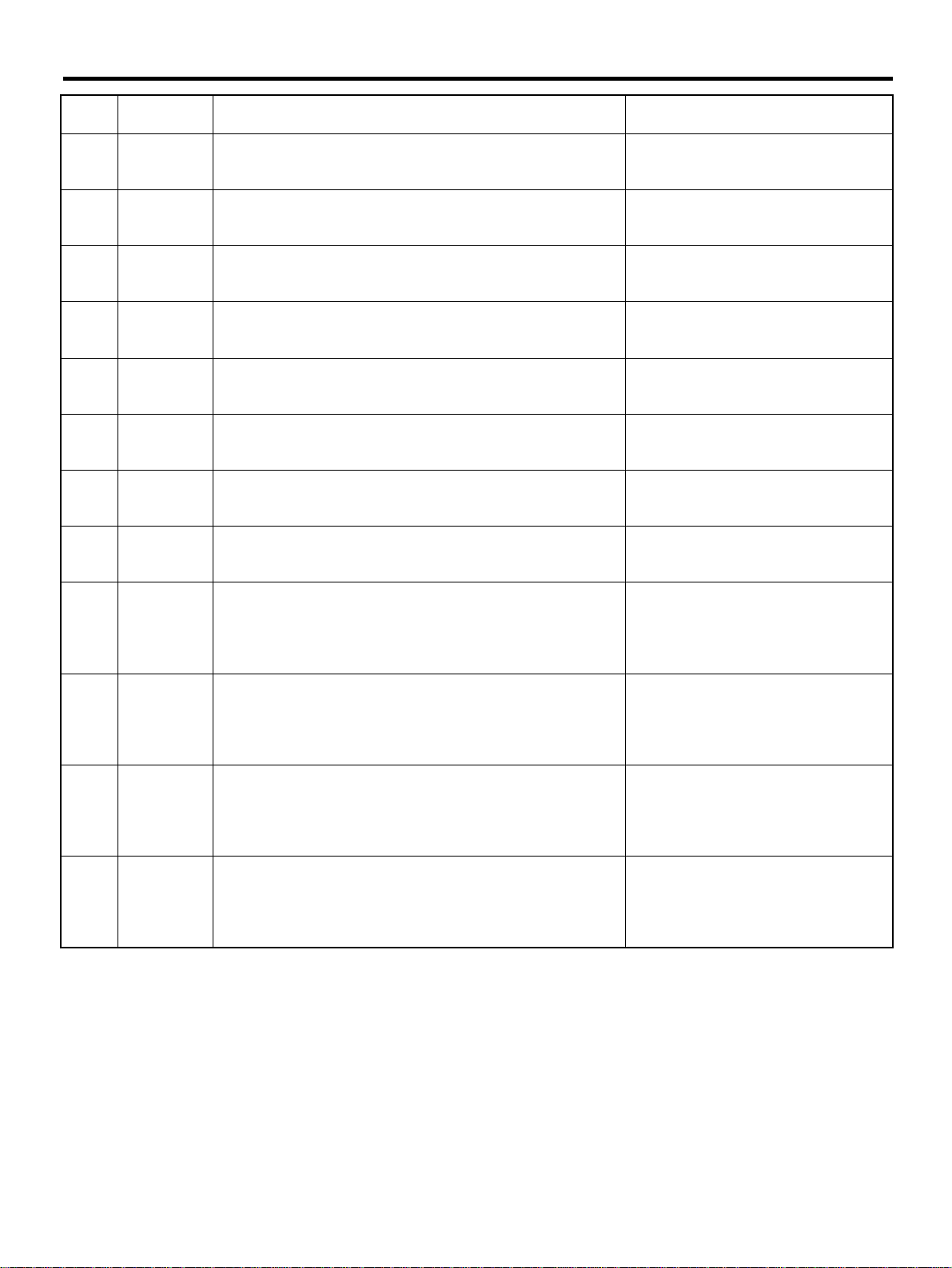
LIST OF DIAGNOSTIC TROUBLE CODE (DTC)
AIRBAG SYSTEM (DIAGNOSTICS)
DTC
42 Provided.
45 Provided.
46 Provided.
51 Provided.
52 Provided.
53 Provided. Side airbag sensor (RH) is faulty.
54 Provided. Side airbag sensor (LH) is faulty.
55 Provided. Side airbag module is inflated.
61 Provided.
62 Provided.
65 Provided.
66 Provided.
Memory
function
Contents of diagnosis Index No.
• Side airbag harness (LH) is faulty.
• Side airbag module (LH) is faulty.
• Airbag control module is faulty.
• Side airbag harness (RH) is shorted to power supply.
• Airbag control module is faulty.
• S ide airbag harness (LH) is shorted to power supply.
• Airbag control module is faulty.
• Side airbag sensor (RH) is faulty.
• S ide airbag harness (RH) is faulty.
• Airbag control module is faulty.
• Side airbag sensor (LH) is faulty.
• Side airbag harness (LH) is faulty.
• Airbag control module is faulty.
• Seat belt pretensioner (RH) circuit is open, shorted or
shorted to ground.
• Airbag control module is faulty.
• Pretensioner is faulty.
• Pretensioner harness is faulty.
• Seat belt pretensioner (LH) circuit is open, shorted or
shorted to ground.
• Airbag control module is faulty.
• Pretensioner is faulty.
• Pretensioner harness is faulty.
• Seat belt pretensioner (RH) circuit is shorted to power sup-
ply.
• Pretensioner is faulty.
• Pretensioner harness is faulty.
• Airbag control module is faulty.
• S eat belt pretensioner (LH) circui t is shorted to power sup -
ply.
• Pretensioner is faulty.
• Pretensioner harness is faulty.
• Airbag control module is faulty.
<Ref. to AB-58, DTC 42, Diagnostic
Chart with Diagnostic Trouble Code
(DTC).>
<Ref. to AB-60, DTC 45, Diagnostic
Chart with Diagnostic Trouble Code
(DTC).>
<Ref. to AB-62, DTC 46, Diagnostic
Chart with Diagnostic Trouble Code
(DTC).>
<Ref. to AB-64, DTC 51, Diagnostic
Chart with Diagnostic Trouble Code
(DTC).>
<Ref. to AB-66, DTC 52, Diagnostic
Chart with Diagnostic Trouble Code
(DTC).>
<Ref. to AB-68, DTC 53, Diagnostic
Chart with Diagnostic Trouble Code
(DTC).>
<Ref. to AB-68, DTC 54, Diagnostic
Chart with Diagnostic Trouble Code
(DTC).>
<Ref. to AB-68, DTC 55, Diagnostic
Chart with Diagnostic Trouble Code
(DTC).>
<Ref. to AB-70, DTC 61, Diagnostic
Chart with Diagnostic Trouble Code
(DTC).>
<Ref. to AB-72, DTC 62, Diagnostic
Chart with Diagnostic Trouble Code
(DTC).>
<Ref. to AB-74, DTC 65, Diagnostic
Chart with Diagnostic Trouble Code
(DTC).>
<Ref. to AB-76, DTC 66, Diagnostic
Chart with Diagnostic Trouble Code
(DTC).>
AB-29
Page 32
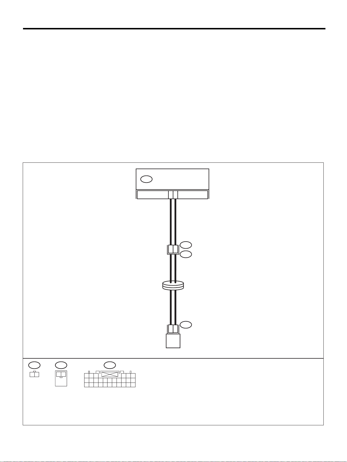
DIAGNOSTIC CHART WITH DIAGNOSTIC TROUBLE CODE (DTC)
AIRBAG SYSTEM (DIAGNOSTICS)
12.Diagnostic Chart with Diagnostic Trouble Code (DTC)
A: DTC 11
DIAGNOSIS:
• Airbag main harness circuit is open, shorted or shorted to ground.
• Airbag module harness (Driver) circuit is open, shorted or shorted to ground.
• Roll connector circuit is open, shorted or shorted to ground.
• Driver's airbag module is faulty.
• Airbag control module is faulty.
CAUTION:
• Before diagnosing the airbag system, be sure to turn the ignition switch OFF, disconnect the
ground cable from the battery, and wait more than 20 seconds before starting to work.
• Before replacing the airbag module, roll controller, control module, and sensor, reconnect each
part and confirm that the warning light operates properly.
• When inspecting the airbag main har ness, disconnec t the dri ver 's air bag module a nd pas senger' s
airbag module connectors for safety reasons.
WIRING DIAGRAM:
AIRBAG CONTROL MODULE
AB6
13
14
1
2
1
2
INFLATOR
(DRIVER SIDE)
AB8
AB3
STEERING
ROLL CONNECTOR
AB7
AB8
1
AB7
2
1 2
1 2 3
7 8 9
18 19 20 21 22 23 24 25 26 27 28
AB6
10 11 12 13 14 15 16 17
4 5 6
AB-00292
AB-30
Page 33

DIAGNOSTIC CHART WITH DIAGNOSTIC TROUBLE CODE (DTC)
Step Value Yes No
1 CHECK DRIVER'S AIRBAG MODULE.
1) Turn the ignition switch OFF, disconnect
battery ground cable, and wait more than
20 seconds.
2) Remove the driver's airbag module. <Ref.
to AB-12, Driver's Airbag Module.>
3) Connect the connector (1F) in test harness
F to connector (AB7).
4) Connect airbag resist or to connecto r (3F) in
test harnes s F.
5) Connect the battery ground cable and turn
the ignition switch ON.
Does the airbag warning light operate properly?
2 CHECK ROL L CONNECTOR.
1) Turn the ignition switch OFF, disconnect
the battery ground cable, and wait more
than 20 second.
2) Disconnect the test harness from the connector (AB7).
3) Remove the lower cover panel, disconnect
the connector (AB3) from (AB8) and connect the connector (1F) in test harness F to
connector (AB8).
4) Connect the airbag resistor to connector
(3F) in test harness F.
5) Connect the battery ground cable and turn
the ignition switch ON.
Does the airbag warning light operate properly?
3 CHECK AIRBAG MAIN HARNESS.
1) Turn the ignition switch OFF, disconnect
the ground cable, and wait more than 20
seconds.
2) Disconnect the airbag resistor from the
connector (3F) in test harness F.
3) Remove the glove box, <Ref. to AB-13,
Passenger's Airbag Module.>, REMOVAL,
Passenger's Airbag Module.> and disconnect connectors (AB10) and (AB9).
4) Disconnect the connector (AB6) from the
airbag control module, and connect the
connector (1I) in test harness I2. <Ref. to
AB-17, Airbag Control Module.>
5) Measure the resista nce betw een connec tor
(2I) in test harness I2 and the connector
(3F) in test harness F.
Connector & terminal
(2I) No. 1 — (3F) No. 4:
(2I) No. 4 — (3F) No. 3:
Is the measured value less than the specified value?
AIRBAG SYSTEM (DIAGNOSTICS)
Operates properly. Replace the
driver's airbag
module. <Ref. to
AB-12, Driver's
Airbag Module.>
Operates properly. Replace the roll
connector. <Ref.
to AB-19, Roll
Connector.>
10 Ω Go to step 4. Replace airbag
Go to step 2.
Go to step 3.
main harness.
<Ref. to AB-15,
Main Harness.>
AB-31
Page 34

DIAGNOSTIC CHART WITH DIAGNOSTIC TROUBLE CODE (DTC)
AIRBAG SYSTEM (DIAGNOSTICS)
Step Value Yes No
4 CHECK AIRBAG MAIN HARNESS.
Measure the resistance of th e conne ctor (2I) in
test harness I2.
Connector & terminal
(2I) No. 1 — No. 4:
(2I) No. 4 — Chassis ground:
(2I) No. 1 — Chassis ground:
Does the measured v alue exceed t he speci fied
value?
1 MΩ Replace the airbag
control module.
<Ref. to AB-17,
Airbag Control
Module.>
Replace airbag
main harness.
<Ref. to AB-15,
Main Harness.>
AB-32
Page 35

MEMO:
DIAGNOSTIC CHART WITH DIAGNOSTIC TROUBLE CODE (DTC)
AIRBAG SYSTEM (DIAGNOSTICS)
AB-33
Page 36
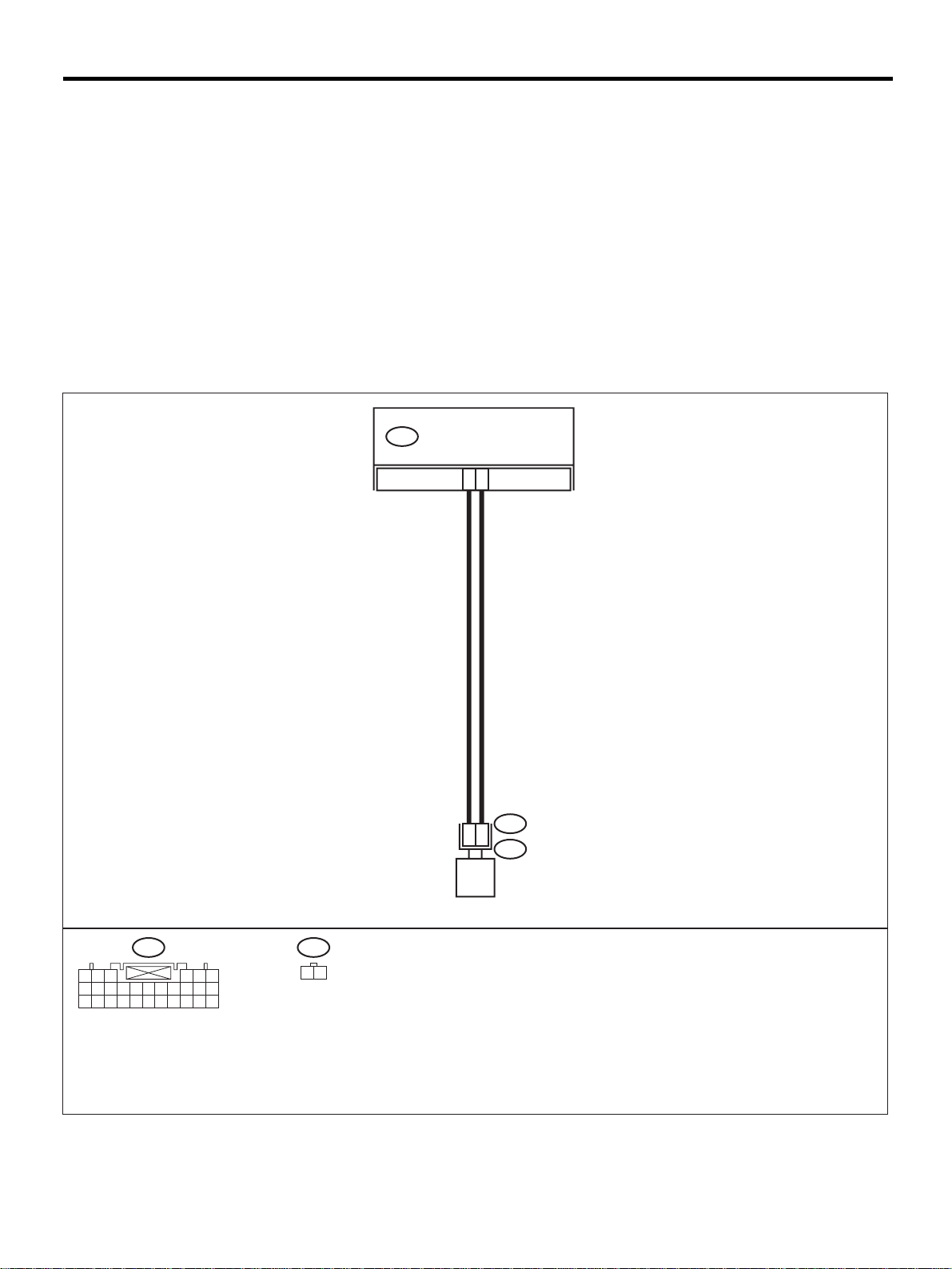
DIAGNOSTIC CHART WITH DIAGNOSTIC TROUBLE CODE (DTC)
AIRBAG SYSTEM (DIAGNOSTICS)
B: DTC 12
DIAGNOSIS:
• Airbag main harness circuit is open, shorted or shorted to ground.
• Airbag module harness (Passenger) circuit is open, shorted or shorted to ground.
• Passenger's airbag module is faulty .
• Airbag control module is faulty.
CAUTION:
• Before diagnosing the airbag system, be sure to turn the ignition switch OFF, disconnect the
ground cable from the battery, and wait more than 20 seconds before starting to work.
• Before replacing the airbag module, roll connector, control module, and sensor, reconnect each
part and confirm that the warning light operates properly.
• When inspecting the airbag main harness, disconnect the airbag module connector of the driver
and passenger seats for safety reasons.
WIRING DIAGRAM:
AIRBAG CONTROL MODULEAB6
10
11
AB6
1 2 3 4 5 6
7 8 9
10 11 12 13 14 15 16 17
18 19 20 21 22 23 24 25 26 27 28
AB9
1 2
AB9
1
2
AB10
INFLATOR
(PASSENGER SIDE)
AB-34
AB-00363
Page 37

DIAGNOSTIC CHART WITH DIAGNOSTIC TROUBLE CODE (DTC)
Step Value Yes No
1 CHECK PASSENGER'S AIRBAG MODULE.
1) Turn the ignition switch OFF, disconnect
the battery ground cable, and wait more
than 20 seconds.
2) Pull out the two stopper pins and lower the
glove box.
3) Disconnect the connector (AB10) from
(AB9).
4) Connect the connecto r (1K) i n te st harness
K to connector (AB9).
5) Connect two airbag resistors to connectors
(3K) and (4K) in test harness K.
6) Connect the battery ground cable and turn
the ignition switch ON.
Does the airbag warning light operate properly?
2 CHECK AIRBAG MAIN HARNESS.
1) Turn the ignition switch OFF, disconnect
the battery ground cable, and wait more
than 20 seconds.
2) Disconnect two airbag resistors from the
connectors (3K) and (4K) in test harness K.
3) Remove lower cover and disconnect the
connector (AB3) from (AB8).
4) Disconnect the connector (AB6) from the
airbag control module, and connect the
connector (1I) in test harness I2. <Ref. to
AB-17, Airbag Control Module.>
5) Measure the resista nce betw een connec tor
(2I) in test harness I2 and the connector
(3K) in test harness K.
Connector & terminal
(2I) No. 2 — (3K) No. 4:
(2I) No. 5 — (3K) No. 3:
Is the measured value less than the specified value?
3 CHECK AIRBAG MAIN HARNESS.
Measure the resistance of th e conne ctor (2I) in
test harness I2.
Connector & terminal
(2I) No. 2 — No. 5:
(2I) No. 2 — Chassis ground:
(2I) No. 5 — Chassis ground:
Does the measured v alue exceed t he speci fied
value?
AIRBAG SYSTEM (DIAGNOSTICS)
Operates properly. Replace the pas-
senger airbag
module. <Ref. to
AB-13, Passenger's Airbag Module.>
10 Ω Go to step 3. Replace airbag
1 MΩ Replace airbag
control module.
<Ref. to AB-17,
Airbag Control
Module.>
Go to step 2.
main harness.
<Ref. to AB-15,
Main Harness.>
Replace airbag
main harness.
<Ref. to AB-15,
Main Harness.>
AB-35
Page 38
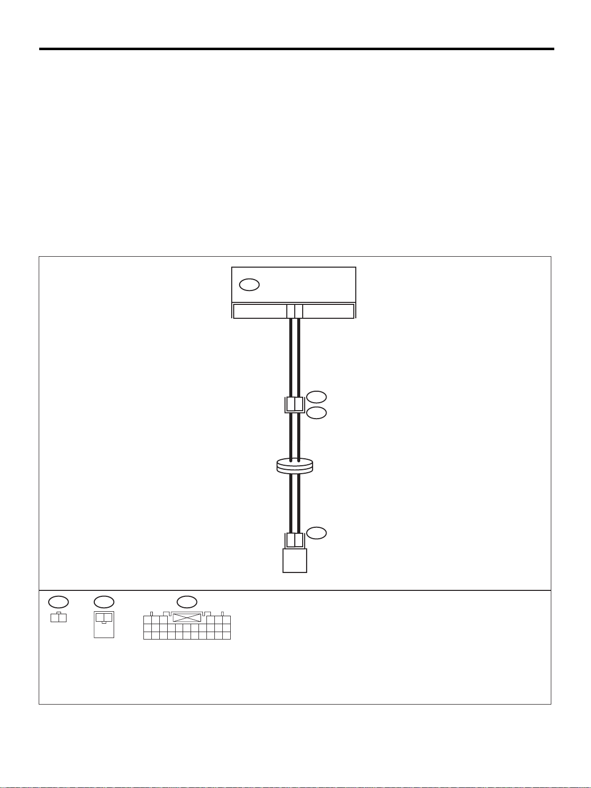
DIAGNOSTIC CHART WITH DIAGNOSTIC TROUBLE CODE (DTC)
AIRBAG SYSTEM (DIAGNOSTICS)
C: DTC 15
DIAGNOSIS:
• Airbag main harness circuit (Driver ) i s shorted to the power supply.
• Airbag module harness (Driver) is shorted to the power supply.
• Roll connector is shorted to the power supply.
• Driver's airbag module is faulty.
• Airbag control module is faulty.
CAUTION:
• Before diagnosing the airbag system, be sure to turn the ignition switch OFF, disconnect the
ground cable from the battery, and wait more than 20 seconds before starting to work.
• Before replacing the airbag module, roll connector, control module, and sensor, reconnect each
part and confirm that the warning light operates properly.
• When inspecting the airbag main har ness, disconnec t the dri ver 's air bag module a nd pas senger' s
airbag module connectors for safety reasons.
WIRING DIAGRAM:
AIRBAG CONTROL MODULE
AB6
13
14
AB8
1
AB8
1
2
AB3
STEERING
ROLL CONNECTOR
AB7
1
2
INFLATOR
(DRIVER SIDE)
AB7
2
1 2
1 2 3
7 8 9
18 19 20 21 22 23 24 25 26 27 28
AB6
10 11 12 13 14 15 16 17
4 5 6
AB-36
AB-00292
Page 39

DIAGNOSTIC CHART WITH DIAGNOSTIC TROUBLE CODE (DTC)
Step Value Yes No
1 CHECK DRIVER'S AIRBAG MODULE.
1) Turn the ignition switch OFF, disconnect
the battery ground cable, and wait more
than 20 seconds.
2) Remove the driver's airbag module. <Ref.
to AB-12, REMOVAL, Driver's Airbag Module.>
3) Connect the connector (AB7) to connector
(1F) in test harness F.
4) Connect the airbag resistor to connector
(3F) in test harness F.
5) Connect the battery ground cable and turn
the ignition switch ON.
Does the airbag warning light operate properly?
2 CHECK ROL L CONNECTOR.
1) Turn the ignition switch OFF, disconnect
the battery ground cable, and wait more
than 20 seconds.
2) Disconnect the test harness from the connector (AB7).
3) Remove the lower cover panel and disconnect the connector (AB3) from (AB8).
4) Connect the connector (1F) in test harness
F to connector (AB8).
5) Connect the airbag resistor to connector
(3F) in test harness F.
6) Connect the battery ground cable and turn
the ignition switch ON.
Does the airbag warning light operate properly?
3 CHECK AIRBAG MAIN HARNESS.
1) Turn the ignition switch OFF, disconnect
the battery ground cable, and wait more
than 20 seconds.
2) Disconnect the airbag resistor from the
connector (3F) in test harness F.
3) Pull out the two stopper pins and lower the
glove box, and disconnect connectors
(AB10) and (AB9).
4) Disconnect the connector (AB6) from the
airbag control module, and connect the
connector (1I) in test harness I2. <Ref. to
AB-17, REMOVAL, Airbag Control Module.>
5) Connect the battery ground cable and turn
the ignition switch ON. (Engine OFF)
6) Measure the voltage between connector
(2I) in test harness I2 and the chassis
ground.
Connector & terminal
(2I) No. 4 (+) — Chassis ground (
(2I) No. 1 (+) — Chassis ground (
Is the measured value less than the specified value?
AIRBAG SYSTEM (DIAGNOSTICS)
Operates properly. Replace the
driver's airbag
module. <Ref. to
AB-12,
REMOVAL,
Driver's Airbag
Module.>
Operates properly. Replace the roll
connector. <Ref.
to AB-19,
REMOVAL, Roll
Connector.>
1 V Replace the airbag
control module.
<Ref. to AB-17,
REMOVAL, Airbag Control Module.>
−−−−
):
−−−−
):
Go to step 2.
Go to step 3.
Replace airbag
main harness.
<Ref. to AB-15,
REMOVAL, Main
Harness.>
AB-37
Page 40
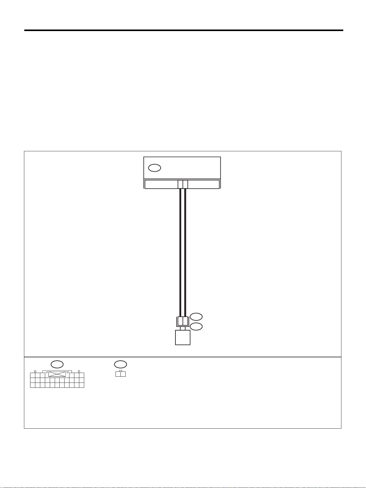
DIAGNOSTIC CHART WITH DIAGNOSTIC TROUBLE CODE (DTC)
AIRBAG SYSTEM (DIAGNOSTICS)
D: DTC 16
DIAGNOSIS:
• Airbag main harness circuit (Passenger) is shor ted to the power supply.
• Airbag module harness (Passenger) is shorted to the power supply.
• Passenger's airbag module is faulty .
• Airbag control module is faulty.
CAUTION:
• Before diagnosing the airbag system, be sure to turn the ignition switch OFF, disconnect the
ground cable from the battery, and wait more than 20 seconds before starting to work.
• Before replacing the airbag module, roll connector, control module, and sensor, reconnect each
part and confirm that the warning light operates properly.
• When inspecting the airbag main harness, disconnect the airbag module connector of the driver
and passenger seats for safety reasons.
WIRING DIAGRAM:
AIRBAG CONTROL MODULEAB6
10
11
AB6
1 2 3 4 5 6
7 8 9
10 11 12 13 14 15 16 17
18 19 20 21 22 23 24 25 26 27 28
AB9
1 2
AB9
1
2
AB10
INFLATOR
(PASSENGER SIDE)
AB-38
AB-00363
Page 41

DIAGNOSTIC CHART WITH DIAGNOSTIC TROUBLE CODE (DTC)
Step Value Yes No
1 CHECK PASSENGER'S AIRBAG MODULE.
1) Turn the ignition switch OFF, disconnect
the battery ground cable, and wait more
than 20 seconds.
2) Pull out the two stopper pins and lower the
glove box.
3) Disconnect the connector (AB10) from
(AB9)
4) Connect the connecto r (1K) i n te st harness
K to connector (AB9).
5) Connect two airbag resistors to connectors
(3K) and (4K) in test harness K.
6) Connect the battery ground cable and turn
the ignition switch ON.
Does the airbag warning light operate properly?
2 CHECK AIRBAG MAIN HARNESS.
1) Turn the ignition switch OFF, disconnect
the battery ground cable, and wait more
than 20 seconds.
2) Disconnect two airbag resistors from the
connectors (3K) and (4K) in test harness K.
3) Remove the lower cover and disconnect
the connector (AB3) from (AB8).
4) Disconnect the connector (AB6) from the
airbag control module, and connect the
connector (1I) in test harness I2. <Ref. to
AB-17, Airbag Control Module.>
5) Measure the voltage between connector
(2I) in test harness I2 and the chassis
ground.
Connector & terminal
(2I) No. 2 — Chassis ground:
(2I) No. 5 — Chassis ground:
Is the measured value less than the specified value?
AIRBAG SYSTEM (DIAGNOSTICS)
Operates properly. Replace the pas-
senger airbag
module. <Ref. to
AB-13, Passenger's Airbag Module.>
1 V Replace the airbag
control module.
<Ref. to AB-17,
Airbag Control
Module.>
Go to step 2.
Replace airbag
main harness.
<Ref. to AB-15,
Main Harness.>
AB-39
Page 42
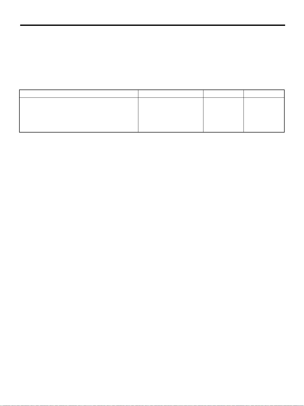
DIAGNOSTIC CHART WITH DIAGNOSTIC TROUBLE CODE (DTC)
AIRBAG SYSTEM (DIAGNOSTICS)
E: DTC 21
DIAGNOSIS:
• Airbag control module is faulty.
CAUTION:
• Before diagnosing the airbag system, be sure to turn the ignition switch OFF, disconnect the
ground cable from the battery, and wait more than 20 seconds before starting to work.
• Before replacing the airbag module, roll connector, control module, and sensor, reconnect each
part and confirm that the warning light operates properly.
Step Value Yes No
1 CHECK IF DTC 21 IS INDICATED.
Read Diagnostic Trouble Code. <Ref. to AB20, Read Diagnostic Trouble Code (DTC).>
Is airbag warning light trouble code 21 indi cated?
DTC 21 is not indicated. Perform clear
memory. <Ref. to
AB-22, Clear
Memory Mode.>
Replace the airbag
control module.
<Ref. to AB-17,
REMOVAL, Airbag Control Module.>
AB-40
Page 43
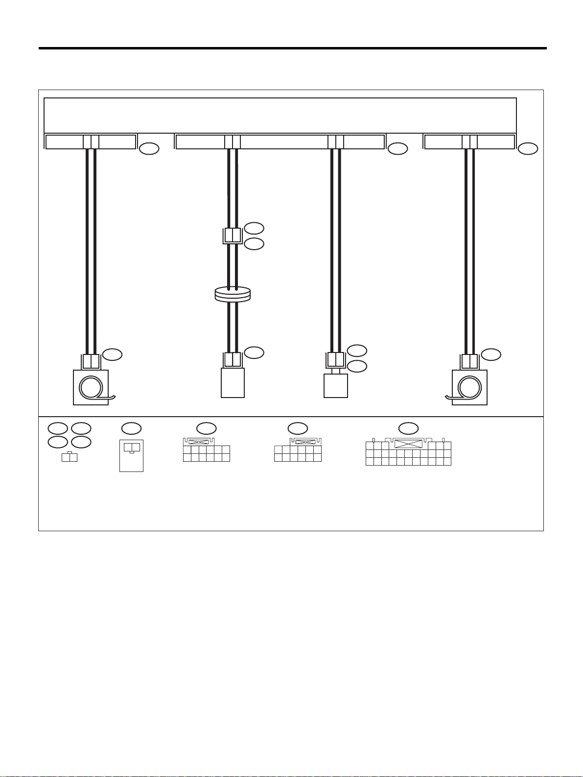
DIAGNOSTIC CHART WITH DIAGNOSTIC TROUBLE CODE (DTC)
F: DTC 22
WIRING DIAGRAM:
2
1
AIRBAG SYSTEM (DIAGNOSTICS)
AIRBAG CONTROL MODULE
13
AB17 AB6
14
1
2
AB8
AB3
STEERING
ROLL
CONNECTOR
10
11
5
6
AB18
AB21
1
2
PRETENSIONER LH
AB8
AB9 AB6AB17
AB26
AB21
1 2
AB7
1 2
1 2 3
7 8 9
1
2
INFLATOR
(DRIVER SIDE)
4 5 6
10 11 12
AB7
(PASSENGER SIDE)
AB18
1 2 3 4 5 6
7 8 9
10 11 12
INFLATOR
AB9
1
2
AB10
PRETENSIONER RH
1 2 3
7 8 9
10 11 12 13 14 15 16 17
18 19 20 21 22 23 24 25 26 27 28
4 5 6
AB26
1
2
This code is indicated when the front airbag and the pretensioner are in operation.
Once this code is indicated, memory is not erasable; therefore change the following parts.
• Airbag control module. <Ref. to AB-17, REMOVAL, Airbag Control Module.>
• Driver's airbag module. <Ref. to AB-12, REMOVAL, Driver's Airbag Module.>
• Passenger's airbag module. <Ref. to AB-13, REMOVAL, Passenger's Airbag Module.>
• Front sub-sensor of both sides. <Ref. to AB-20, REMOVAL, Front Sub Sensor.>
• Front seat belt outer with pretensioner of both sides. <Ref. to SB-7, REMOVAL, Front Seat Belt.>
AB-00367
AB-41
Page 44

DIAGNOSTIC CHART WITH DIAGNOSTIC TROUBLE CODE (DTC)
AIRBAG SYSTEM (DIAGNOSTICS)
G: DTC 23
DIAGNOSIS:
(AB6), (AB17) and (AB18) are not connected properly to airbag control module.
CAUTION:
Before diagnosing the airbag system, be sure to turn t he ignition switch OFF, di sconnect the ground
cable from the battery, and wait more than 20 seconds before starting to work.
Step Value Yes No
1 CHECK POOR CONTACT IN CONNECTORS
(AB6), (AB17) and (AB18).
1) Turn the ignition switch OFF, disconnect
the battery ground cable, and wait more
than 20 seconds.
2) Disconnect the connectors (AB6), (AB17)
and (AB18) from the airbag co ntrol module.
<Ref. to AB-17, Airbag Control Module.>
Check if rust or damage appear on the harness connector and the control module
connector.
2 CHECK POOR CONTACT IN CONNECTORS
(AB6), (AB17) and (AB18).
1) Ensure that connectors are firmly recon nected.
2) Connect the battery ground cable and turn
the ignition switch ON.
Does the air bag warning light operate
properly?
Rust or damage on the harness connector a nd the co ntrol
module are not found.
Operates properly. Finish the diagno-
Go to step 2. Replace the airbag
sis.
control module.
<Ref. to AB-17,
Airbag Control
Module.> Replace
airbag main harness. <Ref. to AB15, Main Harness.> Replace
side airbag harness. <Ref. to AB16, Side Airbag
Harness.>
Replace the airbag
control module.
<Ref. to AB-17,
Airbag Control
Module.>
AB-42
Page 45

MEMO:
DIAGNOSTIC CHART WITH DIAGNOSTIC TROUBLE CODE (DTC)
AIRBAG SYSTEM (DIAGNOSTICS)
AB-43
Page 46
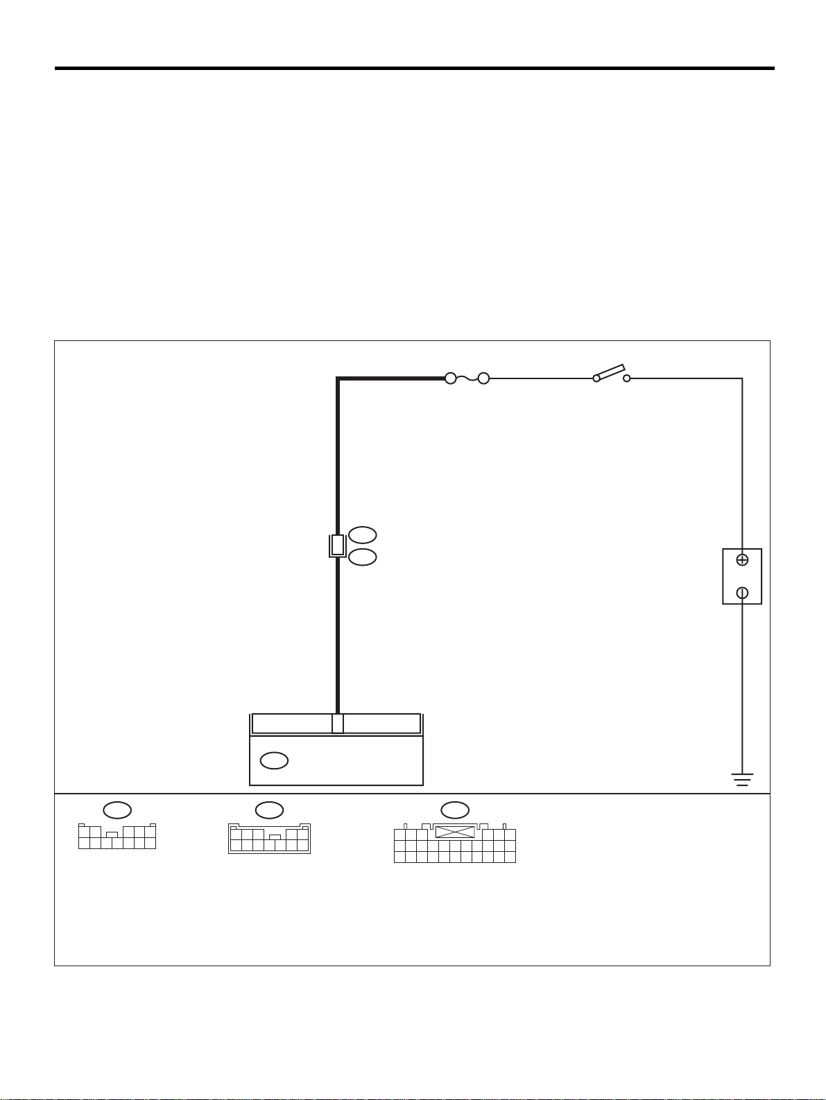
DIAGNOSTIC CHART WITH DIAGNOSTIC TROUBLE CODE (DTC)
AIRBAG SYSTEM (DIAGNOSTICS)
H: DTC 24
DIAGNOSIS:
• Airbag control module is faulty.
• Airbag main harness circuit is open.
• Fuse No, 11 (in joint box) is blown.
• Body harness circuit is open.
CAUTION:
• Before diagnosing the airbag system, be sure to turn the ignition switch OFF, disconnect the
ground cable from the battery, and wait more than 20 seconds before starting to work.
• Before replacing the airbag module, roll connector, control module, and sensor, reconnect each
part and confirm that the warning light operates properly.
• When inspecting the airbag main har ness, disconnec t the dri ver 's air bag module a nd pas senger' s
airbag module connectors for safety reasons.
WIRING DIAGRAM:
6 12
AIRBAG CONTROL MODULE
AB6
B31
AB1
NO. 11
IG SW
BATTERY
1 2
6 7 8 9
B31
3
4 5
10 11 12
AB1
3
45
101112
12
6789
1 2 3
7 8 9
18 19 20 21 22 23 24 25 26 27 28
AB6
10 11 12 13 14 15 16 17
4 5 6
AB-00295
AB-44
Page 47

DIAGNOSTIC CHART WITH DIAGNOSTIC TROUBLE CODE (DTC)
Step Value Yes No
1 CHECK FUSE No. 11 (IN JOINT BOX).
1) Confirm that the ignition switch is turned
OFF.
2) Remove fuse No. 11 (in joint box) and perform visual inspection.
Is fuse No.11 blown?
2 CHECK AIRBAG CONTROL MODULE.
1) Turn the ignition switch OFF, disconnect
the battery ground cable, and wait more
than 20 seconds.
2) Disconnect the connector (AB6) from the
airbag control module. <Ref. to AB-17, Airbag Control Module.>
3) Connect the connector (1I) in test harness
I2 to connector (AB6).
4) Connect the battery ground cable and turn
the ignition switch ON.
5) Measure the voltage between connector
(2I) in test harness I2 and chassis ground.
Connector & terminal
(2I) No. 3 (+) — Chassis ground (
Does the measured val ue exceed the specified value?
3 CHECK BODY MAIN HARNESS.
1) While checking control module, turn the
ignition switch OFF and disconnect the battery ground cable. Wait more than 20 seconds before operation.
2) Disconnect the airbag connector (AB1)
from the body harness (B31).
3) Measure the voltage between the connector (B31) and the chass is ground.
Connector & terminal
(B31) No. 12 (+) — Chassis ground (
Does the measured val ue exceed the specified value?
AIRBAG SYSTEM (DIAGNOSTICS)
Fuse No. 11 is not blown. Go to step 2. Replace fuse No.
11. If fuse No. 11
blows again, repa ir
the body harness.
10 V Replace the airbag
control module.
<Ref. to AB-17,
Airbag Control
Module.>
−−−−
):
10 V Replace airbag
main harness.
<Ref. to AB-15,
Main Harness.>
−−−−
):
Go to step 3.
Repair the body
harness.
AB-45
Page 48
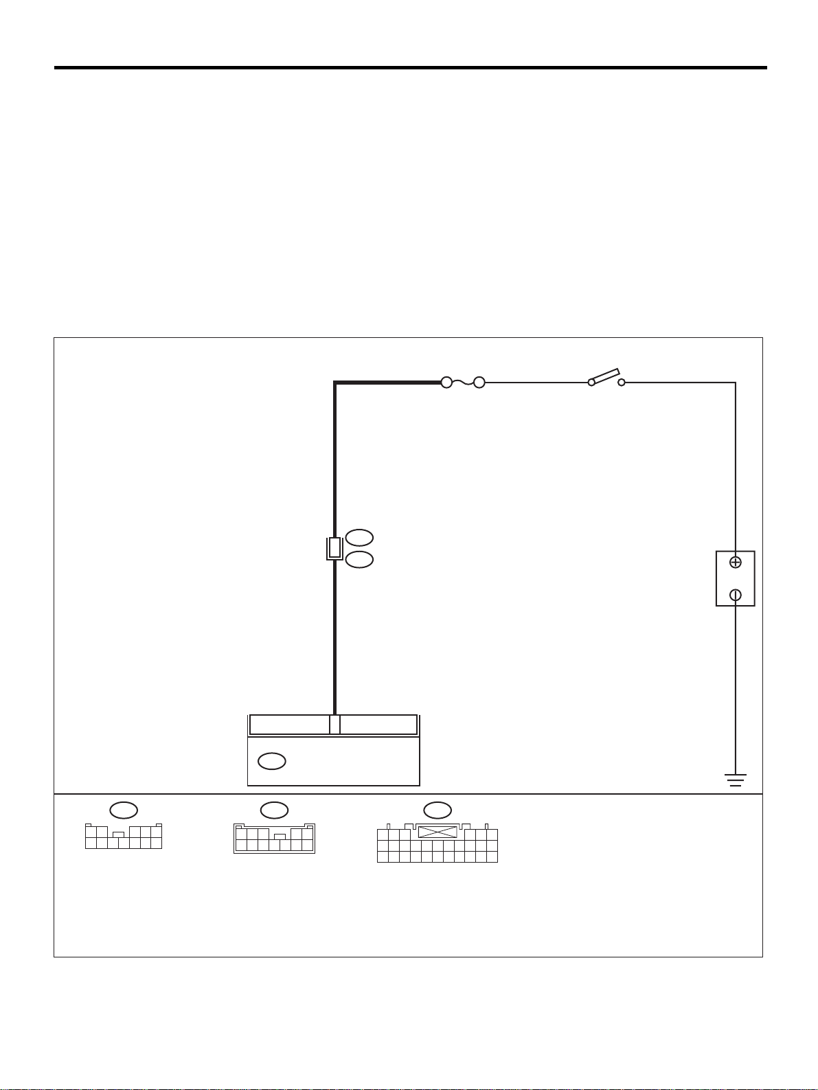
DIAGNOSTIC CHART WITH DIAGNOSTIC TROUBLE CODE (DTC)
AIRBAG SYSTEM (DIAGNOSTICS)
I: DTC 25
DIAGNOSIS:
• Airbag control module is faulty.
• Airbag main harness circuit is open.
• Fuse No. 6 (in joint box) is blown.
• Body harness circuit is open.
CAUTION:
• Before diagnosing the airbag system, be sure to turn the ignition switch OFF, disconnect the
ground cable from the battery, and wait more than 20 seconds before starting to work.
• Before replacing the airbag module, roll connector, control module, and sensor, reconnect each
part and confirm that the warning light operates properly.
• When inspecting the airbag main har ness, disconnec t the dri ver 's air bag module a nd pas senger' s
airbag module connectors for safety reasons.
WIRING DIAGRAM:
NO. 6
B31
AB1
5 11
IG SW
BATTERY
B31
1 2
6 7 8 9
3
4 5
10 11 12
AIRBAG CONTROL MODULEAB6
AB1
3
45
101112
12
6789
1 2 3
7 8 9
18 19 20 21 22 23 24 25 26 27 28
AB6
10 11 12 13 14 15 16 17
4 5 6
AB-00296
AB-46
Page 49

DIAGNOSTIC CHART WITH DIAGNOSTIC TROUBLE CODE (DTC)
Step Value Yes No
1 CHECK FUSE NO. 6 (IN JOINT BOX).
1) Confirm that the ignition switch is turned
OFF.
2) Remove No. 6 fuse (in joint box) and perform visual inspection.
Is fuse No. 6 blown?
2 CHECK AIRBAG CONTROL MODULE.
1) Turn the ignition switch OFF, disconnect
the battery ground cable, and wait more
than 20 seconds.
2) Disconnect the connector (AB6) from airbag control module. <Ref. to AB-17 , Airbag
Control Module.>
3) Connect the connector (1I) in test harness
I2 to connector (AB6).
4) Connect the battery gro und ca ble , an d turn
the ignition switch ON.
5) Measure the voltage between the connector (2I) in test harness I2 and the chassis
ground.
Connector & terminal
(2I) No. 6 (+) — Chassis ground (
Does the measured val ue exceed the specified value?
3 CHECK AIRBAG MAIN HARNESS.
1) While checking control module, turn the
ignition switch OFF and disconnect the battery ground cable. Wait more than 20 seconds before operation.
2) Disconnect the airbag connector (AB1)
from the body harness (B31).
3) Measure the voltage between the connector (B31) and the chass is ground.
Connector & terminal
(B31) No. 11 (+) — Chassis ground (
Does the measured val ue exceed the specified value?
AIRBAG SYSTEM (DIAGNOSTICS)
Fuse No. 6 is not blown. Go to step 2. Replace fuse No.
6. If fuse No. 6 is
blown agai n,
repair the body
harness.
10 V Replace the airbag
control module.
<Ref. to AB-17,
Airbag Control
Module.>
−−−−
):
10 V Replace the airbag
main harness.
<Ref. to AB-15,
Main Harness.>
−−−−
):
Go to step 3.
Repair the body
harness.
AB-47
Page 50
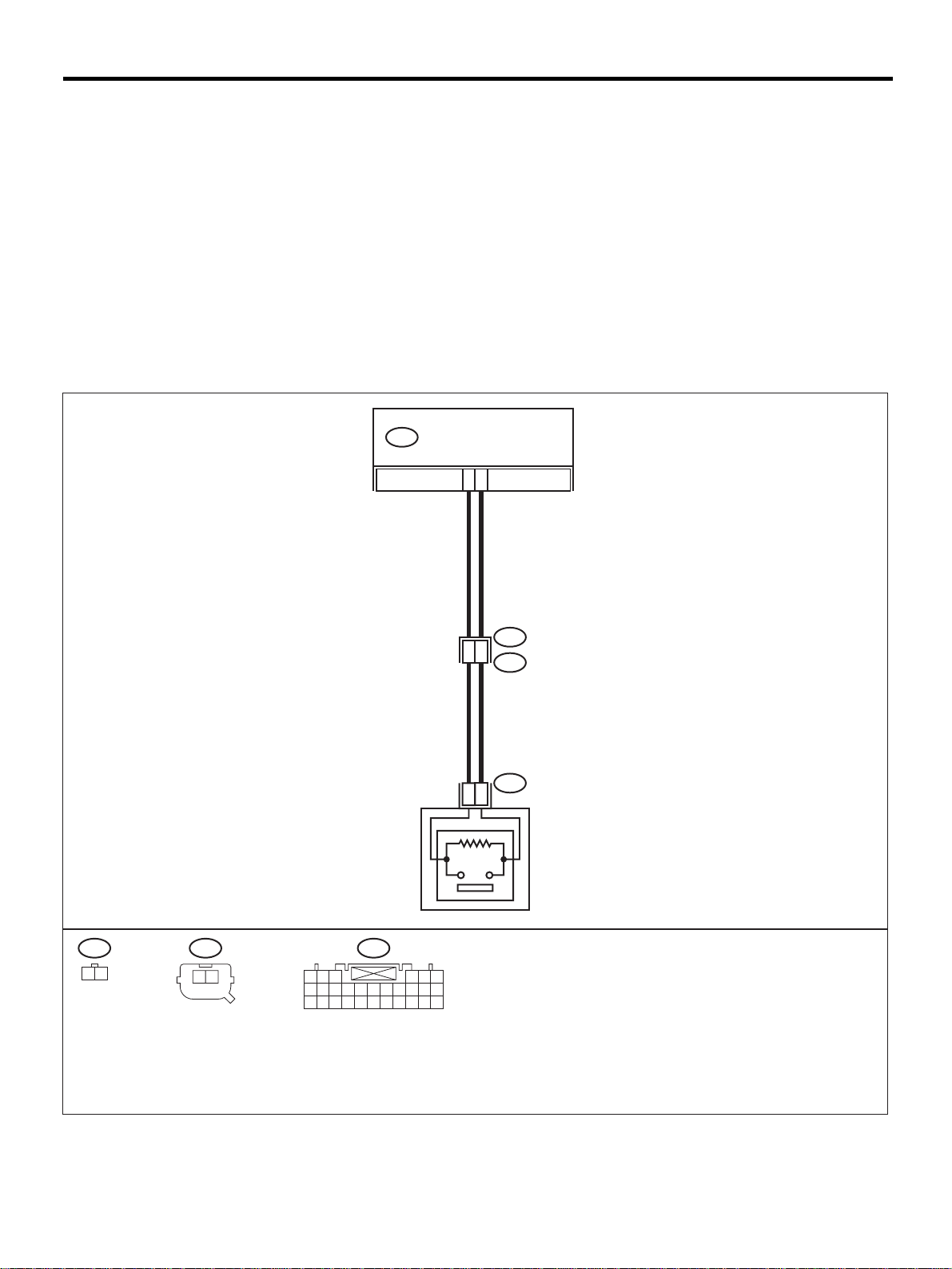
DIAGNOSTIC CHART WITH DIAGNOSTIC TROUBLE CODE (DTC)
AIRBAG SYSTEM (DIAGNOSTICS)
J: DTC 31
DIAGNOSIS:
• Front sub-sensor harness (RH) circuit is shorted.
• Front sub-sensor harness (RH) circuit is open.
• Front sub-sensor (RH) is faulty.
• Airbag control module is faulty.
CAUTION:
• Before diagnosing the airbag system, be sure to turn the ignition switch OFF, disconnect the
ground cable from the battery, and wait more than 20 seconds before starting to work.
• Before replacing the airbag module, roll connector, control module, and sensor, reconnect each
part and confirm that the warning light operates properly.
• When inspecting the airbag main har ness, disconnec t the dri ver 's air bag module a nd pas senger' s
airbag module connectors for safety reasons.
WIRING DIAGRAM:
AIRBAG CONTROL MODULEAB6
9
20
AB15 AB16
1 2
AB14
2
1
AB15
AB16
1
2
FRONT SUB SENSOR RH
AB6
21
1 2 3
7 8 9
10 11 12 13 14 15 16 17
18 19 20 21 22 23 24 25 26 27 28
4 5 6
AB-48
AB-00297
Page 51

DIAGNOSTIC CHART WITH DIAGNOSTIC TROUBLE CODE (DTC)
Step Value Yes No
1 CHECK FRONT SUB-SENSOR (RH) AND
FRONT SUB-SENSOR HARNESS (RH).
1) Turn the ignition switch OFF, disconnect
the battery ground cable, and wait more
than 20 seconds.
2) Disconnect the connector (AB6) from the
airbag control module , and connect the
connector (1I) in test harness I2. <Ref. to
AB-17, Airbag Control Module.>
3) Measure the resistance of the connector
(3I) in test harness I2.
Connector & terminal
(3I) No. 2 — No. 4:
Is the measured value within the specified
range?
2 CHECK FRONT SUB-SENSOR (RH) AND
FRONT SUB-SENSOR HARNESS (RH).
Measure the resistance between connector
(3I) in test harness I2 and the chassis ground.
Connector & terminal
(3I) No. 2 — Chassis ground:
(3I) No. 4 — Chassis ground:
Does the measured v alue exceed t he speci fied
value?
3 CHECK AIRBAG MAIN HARNESS AND
FRONT SUB-SENSOR HARNESS (RH).
1) Disconnect connector (AB16) from the
front sub-sensor. <Ref. to AB-20, Front
Sub Sensor.>
2) Connect connector (IH ) in test ha rness H to
connector (AB16).
3) Measure the resista nce betw een connec tor
(3I) in test harness I2 and con nector (3H) i n
test harness H.
Connector & terminal
(3I) No. 2 — (3H) No. 5:
(3I) No. 4 — (3H) No. 6:
Is the measured value less than the specified value?
4 CHECK AIRBAG MAIN HARNESS AND
FRONT SUB-SENSOR HARNESS (RH).
Measure the resistance between connector
(3I) in test harness I2 and the chassis ground.
Connector & terminal
(3I) No. 2 — Chassis ground:
(3I) No. 4 — Chassis ground:
Does the measured v alue exceed t he speci fied
value?
AIRBAG SYSTEM (DIAGNOSTICS)
750 Ω — 1 KΩ Go to step 2. Go to step 3.
1 MΩ Replace the airbag
control module.
<Ref. to AB-17,
Airbag Control
Module.>
10 Ω Go to step 4. Go to step 5.
1 MΩ Go to step 9. Go to step 5.
Go to step 3.
AB-49
Page 52

DIAGNOSTIC CHART WITH DIAGNOSTIC TROUBLE CODE (DTC)
AIRBAG SYSTEM (DIAGNOSTICS)
Step Value Yes No
5 CHECK AIRBAG MAIN HARNESS
1) Remove the instrument panel. <Ref. to EI35, Instrument Panel Assembly.>
2) Disconnect connector (AB15) from (AB14) ,
and connect connec to r (2F) i n te st harn es s
F to connector (AB14).
3) Measure the resista nce betw een connec tor
(3I) in test harness I2 and co nnect or (3F) i n
test harnes s F.
Connector & terminal
(3I) No. 2 — (3F) No. 6:
(3I) No. 4 — (3F) No. 5:
Is the measured value less than the specified value?
6 CHECK AIRBAG MAIN HARNESS
Measure the resistance between connector
(3I) in test harness I2 and the chassis ground.
Connector & terminal
(3I) No. 2 — Chassis ground:
(3I) No. 4 — Chassis ground:
Does the measured v alue exceed t he speci fied
value?
7 CHECK FRONT SUB-SENSOR HARNESS
(RH).
1) Connect connector (1F ) in tes t harness F to
the connector (AB15) .
2) Measure the resista nce betw een connec tor
(3H) in test harness H and connector (3F)
in the test harness F.
Connector & terminal
(3F) No. 3 — (3H) No. 5:
(3F) No. 4 — (3H) No. 6:
Is the measured value less than the specified value?
8 CHECK FRONT SUB-SENSOR HARNESS
(RH).
Measure the resistance between connector
(3F) in test harness F and the chassis ground.
Connector & terminal
(3F) No. 3 — Chassis ground:
(3F) No. 4 — Chassis ground:
Does the measured v alue exceed t he speci fied
value?
9 CHECK FRONT SUB-SENSOR (RH).
1) Connect connector (2H) in test harness H
to front sub-sensor (RH).
2) Measure the resistance of the connector
(3H) in test harness H.
Connector & terminal
(3H) No. 3 — No. 4:
Is the measured value within the specified
range?
10 Ω Go to step 6. Replace airbag
main harness.
<Ref. to AB-15,
Main Harness.>
1 MΩ Go to step 7. Replace airbag
main harness.
<Ref. to AB-15,
Main Harness.>
10 Ω Go to step 8. Replace th e front
sub-sensor harness (RH) <Ref. to
AB-21, Front Sub
Sensor Harness.>
1 MΩ Go to step 9. Replace the front
sub-sensor harness (RH) <Ref. to
AB-21, Front Sub
Sensor Harness.>
750 Ω — 1 KΩ Go to step 10. Replace the front
sub-sensor (RH)
<Ref. to AB-20,
Front Sub Sensor.>
AB-50
Page 53

DIAGNOSTIC CHART WITH DIAGNOSTIC TROUBLE CODE (DTC)
Step Value Yes No
10 CHECK FRONT SUB-SENSOR (RH).
Measure the resistance between connector
(3H) in tes t harness H and the chassi s ground.
Connector & terminal
(3H) No. 3 — Chassis ground:
(3H) No. 4 — Chassis ground:
Does the measured v alue exceed t he speci fied
value?
AIRBAG SYSTEM (DIAGNOSTICS)
1 MΩ Finish the diagno-
sis.
Replace th e front
sub-sensor (RH)
<Ref. to AB-20,
Front Sub Sensor.>
AB-51
Page 54
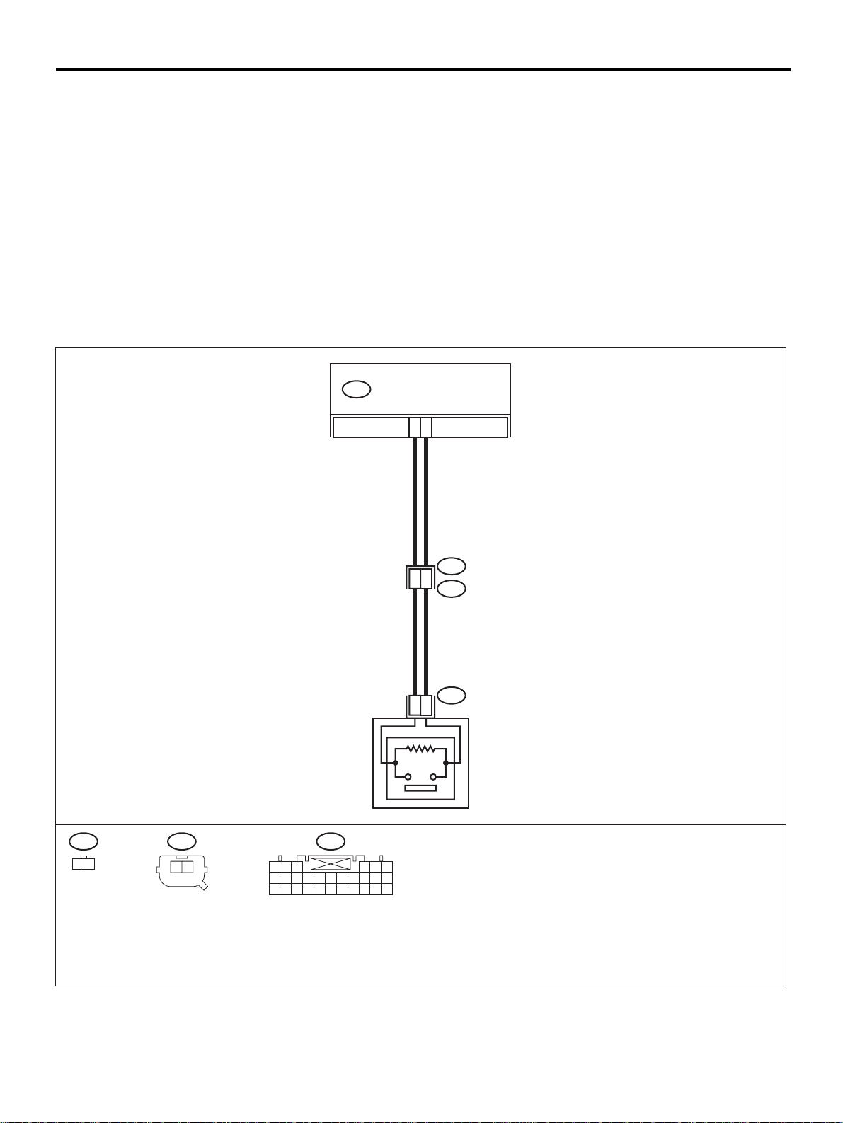
DIAGNOSTIC CHART WITH DIAGNOSTIC TROUBLE CODE (DTC)
AIRBAG SYSTEM (DIAGNOSTICS)
K: DTC 32
DIAGNOSIS:
• Front sub-sensor harness (LH) circuit is shor ted.
• Front sub-sensor harness (LH) circuit is open.
• Front sub-sensor (LH) is faulty.
• Airbag control module is faulty.
CAUTION:
• Before diagnosing the airbag system, be sure to turn the ignition switch OFF, disconnect the
ground cable from the battery, and wait more than 20 seconds before starting to work.
• Before replacing the airbag module, roll connector, control module, and sensor, reconnect each
part and confirm that the warning light operates properly.
• When inspecting the airbag main har ness, disconnec t the dri ver 's air bag module a nd pas senger' s
airbag module connectors for safety reasons.
WIRING DIAGRAM:
AIRBAG CONTROL MODULE
AB6
26
15
AB12
1 2
AB13
AB11
2
1
AB12
AB13
1
2
FRONT SUB SENSOR LH
AB6
21
1 2 3
7 8 9
10 11 12 13 14 15 16 17
18 19 20 21 22 23 24 25 26 27 28
4 5 6
AB-52
AB-00298
Page 55

DIAGNOSTIC CHART WITH DIAGNOSTIC TROUBLE CODE (DTC)
Step Value Yes No
1 CHECK FRONT SUB-SENSOR (LH) AND
FRONT SUB-SENSOR HARNESS (RH).
1) Turn the ignition switch OFF, disconnect
the battery ground cable, and wait more
than 20 seconds.
2) Disconnect connector (AB6) from the airbag control modul e, and co nnect co nnect or
(1I) in the test harness I2 to connector
(AB6). <Ref. to AB-17, Airbag Control
Module.>
3) Measure the resistance of the connector
(3I) in the test harness I2.
Connector & terminal
(3I) No. 1 — No. 3:
Is the measured value within the specified
range?
2 CHECK FRONT SUB-SENSOR (LH) AND
FRONT SUB-SENSOR HARNESS (RH).
Measure the resistance between connector
(3I) in test harness I2 and the chassis ground.
Connector & terminal
(3I) No. 1 — Chassis ground:
(3I) No. 3 — Chassis ground:
Does the measured v alue exceed t he speci fied
value?
3 CHECK AIRBAG MAIN HARNESS AND
FRONT SUB-SENSOR HARNESS (LH).
1) Disconnect the connector (AB13) from the
front sub-sensor. <Ref. to AB-20, Front
Sub Sensor.>
2) Connect connector (1H) in test harness H
to connector (AB13).
3) Measure the resista nce betw een connec tor
(3I) in test harness I2 and con nector (3H) i n
test harness H.
Connector & terminal
(3I) No. 3 — (3H) No. 5:
(3I) No. 1 — (3H) No. 6:
Is the measured value less than the specified value?
4 CHECK AIRBAG MAIN HARNESS AND
FRONT SUB-SENSOR HARNESS (LH).
Measure the resistance between connector
(3I) in test harness I2 and the chassis ground.
Connector & terminal
(3I) No. 3 — Chassis ground:
(3I) No. 1 — Chassis ground:
Does the measured v alue exceed t he speci fied
value?
AIRBAG SYSTEM (DIAGNOSTICS)
750 Ω — 1 KΩ Go to step 2. Go to step 3.
1 MΩ Replace the air-
bag control module. <Ref. to AB17, Airbag Control
Module.>
10 Ω Go to step 4. Go to step 5.
1 MΩ Go to step 9. Go to step 5.
Go to step 3.
AB-53
Page 56

DIAGNOSTIC CHART WITH DIAGNOSTIC TROUBLE CODE (DTC)
AIRBAG SYSTEM (DIAGNOSTICS)
Step Value Yes No
5 CHECK AIRBAG MAIN HARNESS.
1) Remove the instrument panel. <Ref. to EI35, Instrument Panel Assembly.>
2) Disconnect connector (AB11) from (AB12) ,
and connect connec to r (2F) i n te st harn es s
F to (AB11).
3) Measure the resista nce betw een connec tor
(3I) in test harness I2 and co nnect or (3F) i n
test harnes s F.
Connector & terminal
(3I) No. 3 — (3F) No. 6:
(3I) No. 1 — (3F) No. 5:
Is the measured value less than the specified value?
6 CHECK AIRBAG MAIN HARNESS.
Measure the resistance between connector
(3I) in the test harness I2 and the chassis
ground.
Connector & terminal
(3I) No. 3 — Chassis ground:
(3I) No. 1 — Chassis ground:
Does the measured v alue exceed t he speci fied
value?
7 CHECK FRONT SUB-SENSOR HARNESS
(LH).
1) Connect connector (1F ) in tes t harness F to
connector (AB12).
2) Measure the resista nce betw een connec tor
(3H) in test harness H and connector (3F)
in test harness F.
Connector & terminal
(3F) No. 3 — (3H) No. 5:
(3F) No. 4 — (3H) No. 6:
Is the measured value less than the specified value?
8 CHECK FRONT SUB-SENSOR HARNESS
(LH).
Measure the resistance between connector
(3F) in test harness F and the chassis ground.
Connector & terminal
(3F) No. 3 — Chassis ground:
(3F) No. 4 — Chassis ground:
Does the measured v alue exceed t he speci fied
value?
9 CHECK FRONT SUB-SENSOR (LH).
1) Connect connector (2H) in test harness H
to front sub-sensor (LH).
2) Measure the resistance of the connector
(3H) in test harness H.
Connector & terminal
(3H) No. 3 — No. 4:
Is the measured value within the specified
range?
10 Ω Go to step 6. Replace the airbag
main harness.
<Ref. to AB-15,
Main Harness.>
1 MΩ Go to step 7. Replace the airbag
main harness.
<Ref. to AB-15,
Main Harness.>
10 Ω Go to step 8. Replace the fr ont
sub-sensor harness (LH). <Ref. to
AB-15, Main Harness.>
1 MΩ Go to step 9. Replace th e front
sub-sensor harness (LH). <Ref. to
AB-15, Main Harness.>
750 Ω — 1 KΩ Go to step 10. Replace the front
sub-sensor (LH).
<Ref. to AB-20,
Front Sub Sensor.>
AB-54
Page 57

DIAGNOSTIC CHART WITH DIAGNOSTIC TROUBLE CODE (DTC)
Step Value Yes No
10 CHECK FRONT SUB-SENSOR (LH).
Measure the resistance between connector
(3H) in tes t harness H and the chassi s ground.
Connector & terminal
(3H) No. 3 — Chassis ground:
(3H) No. 4 — Chassis ground:
Does the measured v alue exceed t he speci fied
value?
AIRBAG SYSTEM (DIAGNOSTICS)
1 MΩ Finish the diagno-
sis.
Replace th e front
sub-sensor (LH).
<Ref. to AB-20,
Front Sub Sensor.>
AB-55
Page 58
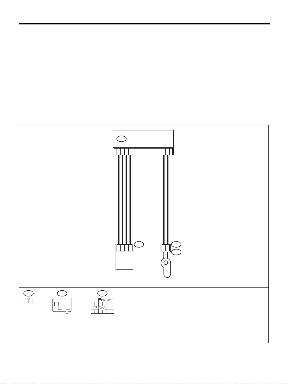
DIAGNOSTIC CHART WITH DIAGNOSTIC TROUBLE CODE (DTC)
AIRBAG SYSTEM (DIAGNOSTICS)
L: DTC 41
DIAGNOSIS:
• Side airbag harness (RH) is faulty.
• Side airbag module (RH) is faulty.
• Airbag control module is faulty.
CAUTION:
• Before diagnosing the airbag system, be sure to turn the ignition switch OFF, disconnect the
ground cable from the battery, and wait more than 20 seconds before starting to work.
• Before replacing the airbag module, roll connector, control module, and sensor, reconnect each
part and confirm that the warning light operates properly.
• When inspecting the airbag main har ness, disconnec t the dri ver 's air bag module a nd pas senger' s
airbag module connectors for safety reasons.
• When inspecting the side airbag harness, disconnect the side airbag module connector and seat
belt pretensioner connector for the safety reasons.
WIRING DIAGRAM:
AIRBAG CONTROL MODULEAB18
9
7
10
12
2
1
AB24 AB28 AB18
1 2
12
34
1 2 3
7 8 9
4 5 6
10 11 12
1
4
2
SIDE AIRBAG
SENSOR RH
3
AB-56
1
2
INFLATOR
(SIDE RH)
AB24AB28
AB25
AB-00299
Page 59

DIAGNOSTIC CHART WITH DIAGNOSTIC TROUBLE CODE (DTC)
Step Value Yes No
1 CHECK SIDE AIRBAG MODULE.
1) Turn the ignition switch OFF, disconnect
the battery ground cable, and wait more
than 20 seconds.
2) Disconnect the connector (AB26) from the
seat belt pretensioner (RH). <Ref. to AB17, REMOVAL, Airbag Control Module .>
3) Disconnect connector (AB25) from (AB24) ,
and connect connec to r (1F) i n te st harn es s
F to (AB24).
4) Connect air bag resistor to connector (3F)
in test harness F.
5) Connect the battery gro und ca ble , an d turn
the ignition switch ON.
Does the airbag warning light operate properly?
2 CHECK SIDE AIRBAG HARNESS (RH).
1) Turn the ignition switch OFF, disconnect
the battery ground cable, and wait more
than 20 seconds.
2) Disconnect airbag resistor from test harness.
3) Disconnect the connector (AB18) from air
bag control module. <Ref. to AB-17,
REMOVAL, Airbag Control Module.>
4) Connect connector (1I) in te st harne ss I2 to
connector (AB18).
5) Measure the resista nce betw een connec tor
(3I) in test harness I2 and co nnect or (3F) i n
test harnes s F.
Connector & terminal
(3I) No. 7 — (3F) No. 4:
(3I) No. 9 — (3F) No. 3:
Is the measured value less than the specified value?
3 CHECK SIDE AIRBAG HARNESS (RH).
Measure the resistance of the connector (3F)
in test harness F.
Connector & terminal
(3F) No. 3 — No. 4:
Does the measured v alue exceed t he speci fied
value?
4 CHECK SIDE AIRBAG HARNESS (RH).
Measure the resistance between connector
(3F) in test harness F and the chassis ground.
Connector & terminal
(3F) No. 3 — Chassis ground:
(3F) No. 4 — Chassis ground:
Does the measured v alue exceed t he speci fied
value?
AIRBAG SYSTEM (DIAGNOSTICS)
Operates properly. Replace front seat
with side airbag
module (RH).
<Ref. to SB-7,
Front Seat Belt.>
10 Ω Go to step 3. Replace side air-
1 MΩ Go to step 4. Replace side air-
1 MΩ Replace the airbag
control module.
<Ref. to AB-17,
Airbag Control
Module.>
Go to step 2.
bag harness.
<Ref. to AB-16,
Side Airbag Harness.>
bag harness.
<Ref. to AB-16,
Side Airbag Harness.>
Replace side airbag harness.
<Ref. to AB-16,
Side Airbag Harness.>
AB-57
Page 60
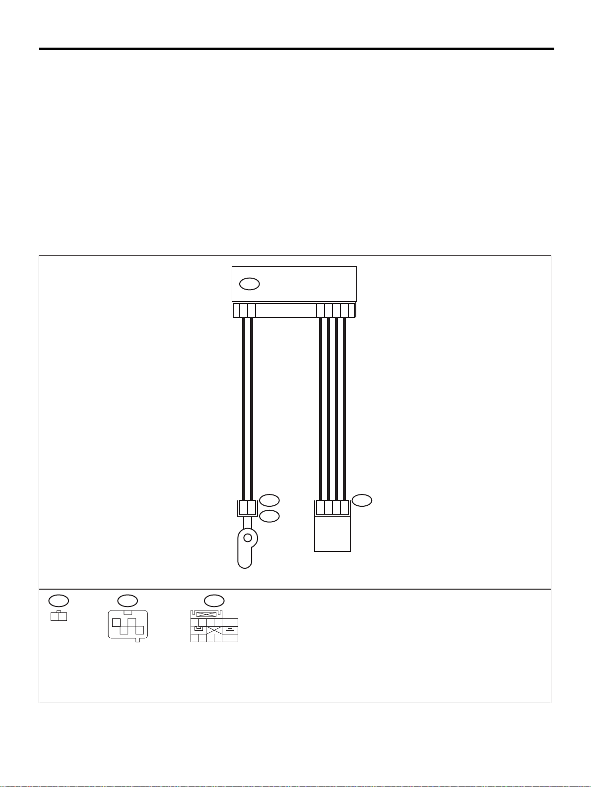
DIAGNOSTIC CHART WITH DIAGNOSTIC TROUBLE CODE (DTC)
AIRBAG SYSTEM (DIAGNOSTICS)
M: DTC 42
DIAGNOSIS:
• Side airbag harness (LH) is faulty.
• Side airbag module (LH) is faulty.
• Airbag control module is faulty.
CAUTION:
• Before diagnosing the airbag system, be sure to turn the ignition switch OFF, disconnect the
ground cable from the battery, and wait more than 20 seconds before starting to work.
• Before replacing the airbag module, roll connector, control module, and sensor, reconnect each
part and confirm that the warning light operates properly.
• When inspecting the airbag main har ness, disconnec t the dri ver 's air bag module a nd pas senger' s
airbag module connectors for safety reasons.
• When inspecting the side airbag harness, disconnect the side airbag module connector and seat
belt pretensioner connector for the safety reasons.
WIRING DIAGRAM:
AIRBAG CONTROL MODULE
AB17
5
1
INFLATOR
(SIDE LH)
6
AB19 AB23
2
AB20
7
9
10
1
4
2
SIDE AIRBAG
SENSOR LH
12
3
AB19
1 2
AB23
12
34
1 2 3
7 8 9
AB17
4 5 6
10 11 12
AB-00300
AB-58
Page 61

DIAGNOSTIC CHART WITH DIAGNOSTIC TROUBLE CODE (DTC)
Step Value Yes No
1 CHECK SIDE AIRBAG MODULE.
1) Turn the ignition switch OFF, disconnect
the battery ground cable, and wait more
than 20 seconds.
2) Disconnect the connector (AB21) from the
seat belt pretensioner (LH). <Ref. to AB17, REMOVAL, Airbag Control Module .>
3) Disconnect connector (AB20) from (AB19) ,
and connect connec to r (1F) i n te st harn es s
F to (AB19).
4) Connect airbag resist or to connecto r (3F) in
test harnes s F.
5) Connect the battery gro und ca ble , an d turn
the ignition switch ON.
Does the air bag warning light operate
properly?
2 CHECK SIDE AIRBAG HARNESS (LH).
1) Turn ignition switch OFF, disconnect the
battery ground cable, and wait more than
20 seconds.
2) Disconnect airbag resistor from the test
harness.
3) Disconnect the connector (AB17) from the
airbag control module. <Ref. to AB-17,
REMOVAL, Airbag Control Module.>
4) Connect connector (1I) in te st harne ss I2 to
connector (AB17).
5) Measure the resista nce betw een connec tor
(3I) in test harness I2 and co nnect or (3F) i n
test harnes s F.
Connector & terminal
(3I) No. 10 — (3F) No. 3:
(3I) No. 12 — (3F) No. 4:
Is the measured value less than the specified value?
3 CHECK SIDE AIRBAG HARNESS (LH).
Measure the resistance of the connector (3F)
in test harness F.
Connector & terminal
(3F) No. 3 — No. 4:
Does the measured v alue exceed t he speci fied
value?
4 CHECK SIDE AIRBAG HARNESS (LH).
Measure the resistance between connector
(3F) in test harness F and the chassis ground.
Connector & terminal
(3F) No. 3 — Chassis ground:
(3F) No. 4 — Chassis ground:
Does the measured v alue exceed t he speci fied
value?
AIRBAG SYSTEM (DIAGNOSTICS)
Operates properly. Replace front seat
with side airbag
module (LH).
<Ref. to SB-7,
Front Seat Belt.>
10 Ω Go to step 3. Replace side air-
1 MΩ Go to step 4. Replace side air-
1 MΩ Replace the airbag
control module.
<Ref. to AB-17,
Airbag Control
Module.>
Go to step 2.
bag harness.
<Ref. to AB-16,
Side Airbag Harness.>
bag harness.
<Ref. to AB-16,
Side Airbag Harness.>
Replace side airbag harness.
<Ref. to AB-16,
Side Airbag Harness.>
AB-59
Page 62
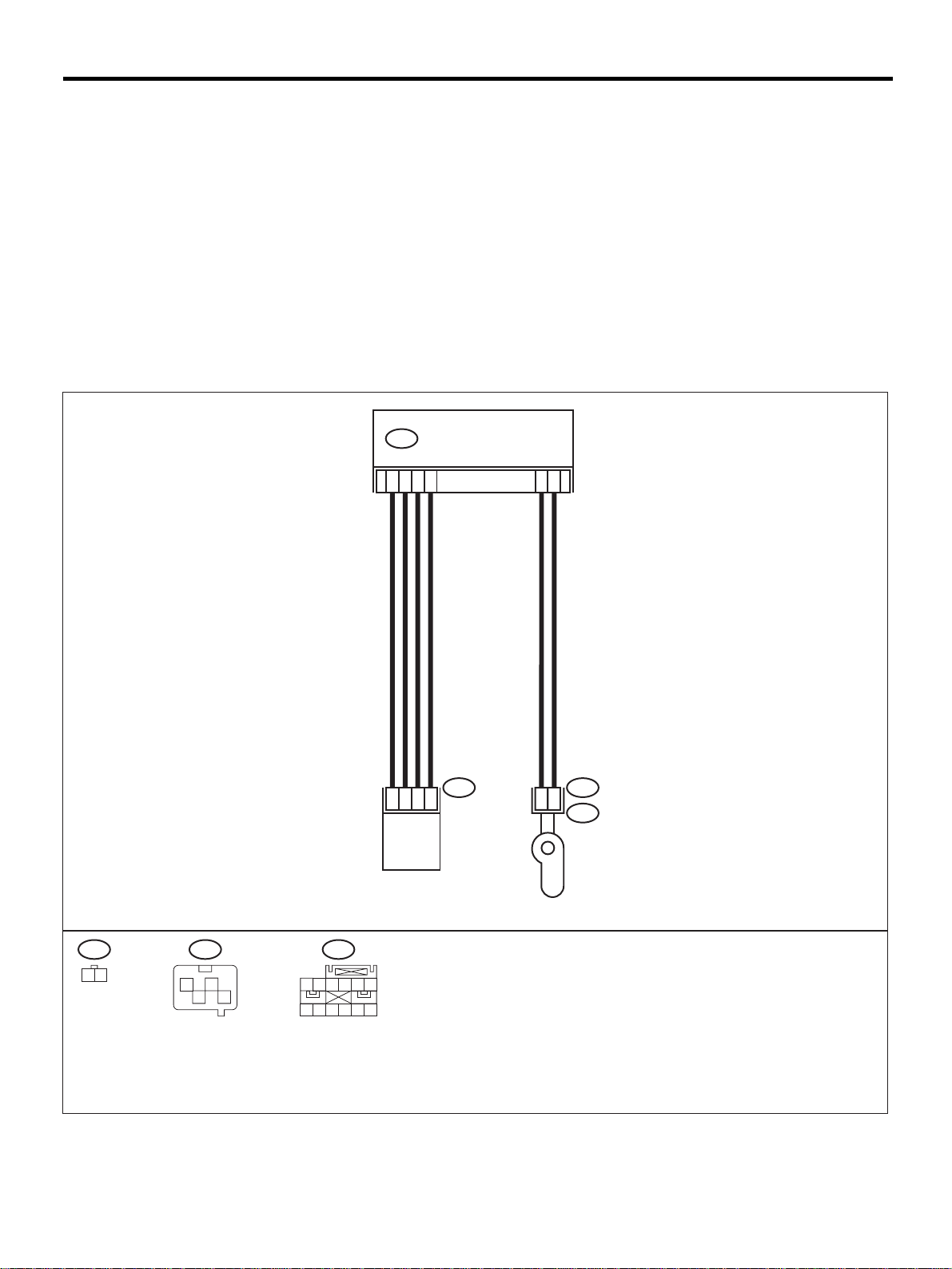
DIAGNOSTIC CHART WITH DIAGNOSTIC TROUBLE CODE (DTC)
AIRBAG SYSTEM (DIAGNOSTICS)
N: DTC 45
DIAGNOSIS:
• Side airbag harness (RH) is shorted to power supply.
• Airbag control module is faulty.
CAUTION:
• Before diagnosing the airbag system, be sure to turn the ignition switch OFF, disconnect the
ground cable from the battery, and wait more than 20 seconds before starting to work.
• Before replacing the airbag module, roll connector, control module, and sensor, reconnect each
part and confirm that the warning light operates properly.
• When inspecting the airbag main har ness, disconnec t the dri ver 's air bag module a nd pas senger' s
airbag module connectors for safety reasons.
• When inspecting the side airbag harness, disconnect the side airbag module connector and seat
belt pretensioner connector for the safety reasons.
WIRING DIAGRAM:
AIRBAG CONTROL MODULEAB18
9
7
10
12
2
1
AB24 AB28 AB18
1 2
12
34
1 2 3
7 8 9
4 5 6
10 11 12
1
4
2
SIDE AIRBAG
SENSOR RH
3
AB-60
1
2
INFLATOR
(SIDE RH)
AB24AB28
AB25
AB-00299
Page 63

DIAGNOSTIC CHART WITH DIAGNOSTIC TROUBLE CODE (DTC)
Step Value Yes No
1 CHECK SIDE AIRBAG MODULE.
1) Turn the ignition switch OFF, disconnect
the battery ground cable, and wait more
than 20 seconds.
2) Disconnect the connector (AB26) from the
seat belt pretensioner (RH ). <Ref. to SE-7,
Front Seat.>
3) Disconnect the connector (AB25) from
(AB24), and connect connec tor (1F) i n test
harness F to (AB24).
4) Connect airbag resist or to connecto r (3F) in
test harnes s F.
5) Connect the battery gro und ca ble , an d turn
the ignition switch ON.
Does air bag warning light operate properly?
2 CHECK SIDE AIRBAG HARNESS (RH).
1) Turn the ignition switch OFF, disconnect
the battery ground cable, and wait more
than 20 seconds.
2) Disconnect airbag resistor from the test
harness.
3) Disconnect the connector (AB18) from the
airbag control module. <Ref. to AB-17, Airbag Control Module.>
4) Connect connector (1I) in te st harne ss I2 to
connector (AB18).
5) Connect the battery gro und ca ble , an d turn
the ignition switch ON.
6) Measure the voltage between connector
(3I) in test harness I2 and the chassis
ground.
Connector & terminal
(3I) No. 7 (+) — Chassis ground (
(3I) No. 9 (+) — Chassis ground (
Is the measured value less than the specified value?
−−−−
−−−−
AIRBAG SYSTEM (DIAGNOSTICS)
Operates properly. Replace front seat
with side airbag
module (RH).
<Ref. to SE-7,
Front Seat.>
1 V Replace the airbag
control module.
<Ref. to AB-17,
Airbag Control
Module.>
):
):
Go to step 2.
Replace side airbag harness.
<Ref. to AB-16,
Side Airbag Harness.>
AB-61
Page 64
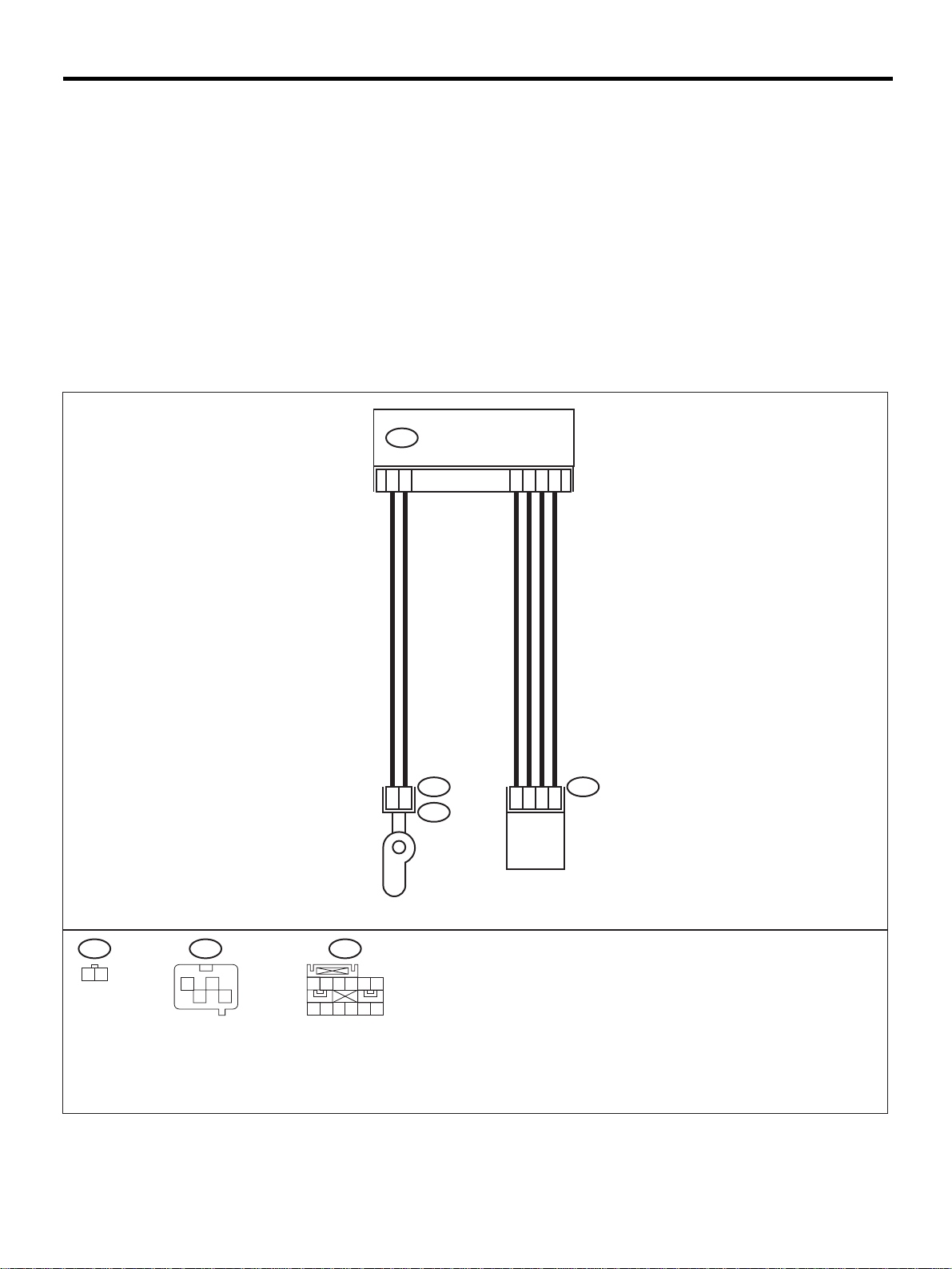
DIAGNOSTIC CHART WITH DIAGNOSTIC TROUBLE CODE (DTC)
AIRBAG SYSTEM (DIAGNOSTICS)
O: DTC 46
DIAGNOSIS:
• Side airbag harness (LH) is shorted to power supply.
• Airbag control module is faulty.
CAUTION:
• Before diagnosing the airbag system, be sure to turn the ignition switch OFF, disconnect the
ground cable from the battery, and wait more than 20 seconds before starting to work.
• Before replacing the airbag module, roll connector, control module, and sensor, reconnect each
part and confirm that the warning light operates properly.
• When inspecting the airbag main har ness, disconnec t the dri ver 's air bag module a nd pas senger' s
airbag module connectors for safety reasons.
• When inspecting the side airbag harness, disconnect the side airbag module connector and seat
belt pretensioner connector for the safety reasons.
WIRING DIAGRAM:
AIRBAG CONTROL MODULE
AB17
5
1
INFLATOR
(SIDE LH)
6
AB19 AB23
2
AB20
7
9
10
1
4
2
SIDE AIRBAG
SENSOR LH
12
3
AB19
1 2
AB23
12
34
1 2 3
7 8 9
AB17
4 5 6
10 11 12
AB-00300
AB-62
Page 65

DIAGNOSTIC CHART WITH DIAGNOSTIC TROUBLE CODE (DTC)
Step Value Yes No
1 CHECK SIDE AIRBAG MODULE.
1) Turn the ignition switch OFF, disconnect
the battery ground cable, and wait more
than 20 seconds.
2) Disconnect connector (AB21) from the
seat belt pretensioner (LH) . <Ref. to SE-7,
Front Seat.>
3) Disconnect connector (AB20) from (AB19) ,
and connect connec to r (1F) i n te st harn es s
F to (AB19).
4) Connect airbag resist or to connecto r (3F) in
test harnes s F.
5) Connect the battery ground cable and turn
the ignition switch ON.
Does air bag warning light operate properly?
2 CHECK SIDE AIRBAG HARNESS (LH).
1) Turn the ignition switch OFF, disconnect
the battery ground cable, and wait more
than 20 seconds.
2) Disconnect airbag resistor from the test
harness.
3) Disconnect the connector (AB17) from the
airbag control module. <Ref. to AB-17, Airbag Control Module.>
4) Connect connector (1I) in te st harne ss I2 to
connector (AB17).
5) Connect the battery gro und ca ble , an d turn
the ignition switch ON.
6) Measure the voltage between connector
(3I) in test harness I2 and the chassis
ground.
Connector & terminal
(3I) No. 10 (+) — Chassis ground (
(3I) No. 12 (+) — Chassis ground (
Is the measured value less than the specified value?
AIRBAG SYSTEM (DIAGNOSTICS)
Operates properly. Replace front seat
with side airbag
module (LH).
<Ref. to SE-7,
Front Seat.>
1 V Replace the air-
bag control module. <Ref. to AB17, Airbag Control
Module.>
−−−−
):
−−−−
):
Go to step 2.
Replace side airbag harness.
<Ref. to AB-16,
Side Airbag Harness.>
AB-63
Page 66
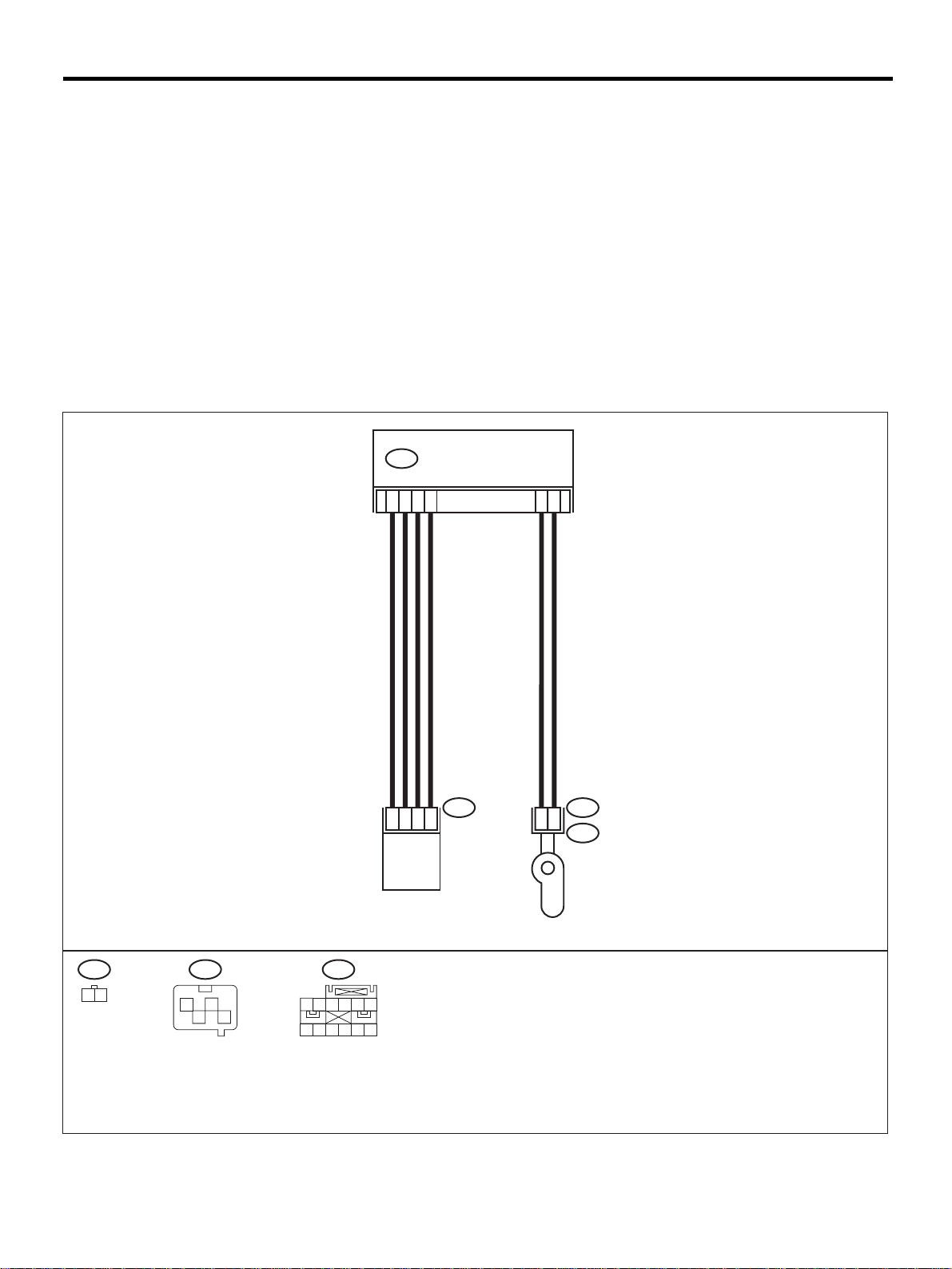
DIAGNOSTIC CHART WITH DIAGNOSTIC TROUBLE CODE (DTC)
AIRBAG SYSTEM (DIAGNOSTICS)
P: DTC 51
DIAGNOSIS:
• Side airbag sensor (RH) is faulty.
• Side airbag harness (RH) is faulty.
• Airbag control module is faulty.
CAUTION:
• Before diagnosing the airbag system, be sure to turn the ignition switch OFF, disconnect the
ground cable from the battery, and wait more than 20 seconds before starting to work.
• Before replacing the airbag module, roll connector, control module, and sensor, reconnect each
part and confirm that the warning light operates properly.
• When inspecting the airbag main har ness, disconnec t the dri ver 's air bag module a nd pas senger' s
airbag module connectors for safety reasons.
• When inspecting the side airbag harness, disconnect the side airbag module connector and seat
belt pretensioner connector for the safety reasons.
WIRING DIAGRAM:
AIRBAG CONTROL MODULEAB18
9
7
10
12
2
1
AB24 AB28 AB18
1 2
12
34
1 2 3
7 8 9
4 5 6
10 11 12
1
4
2
SIDE AIRBAG
SENSOR RH
3
AB-64
1
2
INFLATOR
(SIDE RH)
AB24AB28
AB25
AB-00299
Page 67

DIAGNOSTIC CHART WITH DIAGNOSTIC TROUBLE CODE (DTC)
Step Value Yes No
1 CHECK SIDE AIRBAG HARNESS (RH).
1) Turn the ignition switch OFF, disconnect
the battery ground cable, and wait more
than 20 seconds.
2) Disconnect connecto r (AB26) from the seat
belt pretensioner (RH). <Ref. to SB-7, Front
Seat Belt.>
3) Disconnect connector (AB25) from (AB24).
4) Disconnect connector (AB18) from the airbag control module. < Ref. to AB-17 , Airbag
Control Module.>
5) Connect connector (1I) in te st harne ss I2 to
the connector (AB18) .
6) Disconnect connector (AB2 8) from the side
airbag sensor (RH), and connect connector (1G) in test harness G to connector
(AB28).
7) Measure the resista nce betw een connec tor
(3I) in test harness I 2 and c onnector (3G) in
test harness G.
Connector & terminal
(3I) No. 17 — (3G) No. 2:
(3I) No. 18 — (3G) No. 4:
(3I) No. 19 — (3G) No. 1:
(3I) No. 20 — (3G) No. 5:
Is the measured value less than the specified value?
2 CHECK SIDE AIRBAG HARNESS (RH).
Measure the resistance between connector
(3I) in test harness I2 and the chassis ground.
Connector & terminal
(3I) No. 17 — Chassis ground:
(3I) No. 18 — Chassis ground:
(3I) No. 19 — Chassis ground:
(3I) No. 20 — Chassis ground:
Does the measured v alue exceed t he speci fied
value?
AIRBAG SYSTEM (DIAGNOSTICS)
10 Ω Go to step 2. Replace side air-
bag harness.
<Ref. to AB-16,
Side Airbag Harness.>
1 MΩ Replace side air-
bag sensor (RH).
<Ref. to AB-18,
Side Airbag Sensor.> When senso r
replacement is n ot
OK, replace the
airbag control
module. <Ref. to
AB-17, Airbag
Control Module.>
Replace side airbag harness.
<Ref. to AB-16,
Side Airbag Harness.>
AB-65
Page 68
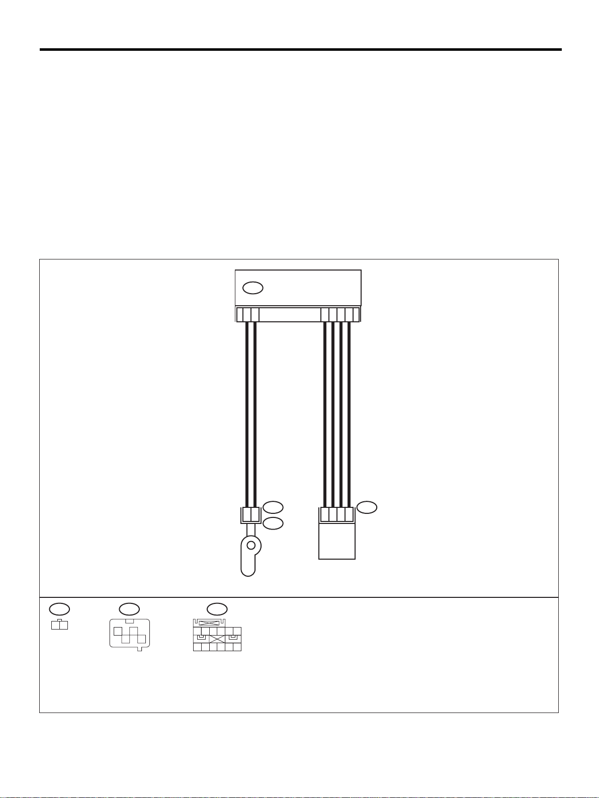
DIAGNOSTIC CHART WITH DIAGNOSTIC TROUBLE CODE (DTC)
AIRBAG SYSTEM (DIAGNOSTICS)
Q: DTC 52
DIAGNOSIS:
• Side airbag sensor (LH) is faulty.
• Side airbag harness (LH) is faulty.
• Airbag control module is faulty.
CAUTION:
• Before diagnosing the airbag system, be sure to turn the ignition switch OFF, disconnect the
ground cable from the battery, and wait more than 20 seconds before starting to work.
• Before replacing the airbag module, roll connector, control module, and sensor, reconnect each
part and confirm that the warning light operates properly.
• When inspecting the airbag main har ness, disconnec t the dri ver 's air bag module a nd pas senger' s
airbag module connectors for safety reasons.
• When inspecting the side airbag harness, disconnect the side airbag module connector and seat
belt pretensioner connector for the safety reasons.
WIRING DIAGRAM:
AIRBAG CONTROL MODULE
AB17
5
1
INFLATOR
(SIDE LH)
6
AB19 AB23
2
AB20
7
9
10
1
4
2
SIDE AIRBAG
SENSOR LH
12
3
AB19
1 2
AB23
12
34
1 2 3
7 8 9
AB17
4 5 6
10 11 12
AB-00300
AB-66
Page 69

DIAGNOSTIC CHART WITH DIAGNOSTIC TROUBLE CODE (DTC)
Step Value Yes No
1 CHECK SIDE AIRBAG HARNESS (LH).
1) Turn the ignition switch OFF, disconnect
the battery ground cable, and wait more
than 20 seconds.
2) Disconnect the connector (AB21) from the
seat belt pretensioner (LH) . <Ref. to SB-7,
Front Seat Belt.>
3) Disconnect connector (AB20) from (AB19).
4) Disconnect connector (AB17) from the airbag control module. <Ref. to AB-17 , Airbag
Control Module.>
5) Connect connector (1I) in te st harne ss I2 to
connector (AB17).
6) Disconnect connector (AB2 3) from the side
airbag sensor (LH), and connect connector (1G) in test harness G to connector
(AB23).
7) Measure the resista nce betw een connec tor
(3I) in test harness I 2 and c onnector (3G) in
test harness G.
Connector & terminal
(3I) No. 5 — (3G) No. 5:
(3I) No. 14 — (3G) No. 1:
(3I) No. 15 — (3G) No. 4:
(3I) No. 16 — (3G) No. 2:
Is the measured value less than the specified value?
2 CHECK SIDE AIRBAG HARNESS (RH).
Measure the resistance between connector
(3I) in test harness I2 and the chassis ground.
Connector & terminal
(3I) No. 5 — Chassis ground:
(3I) No. 14 — Chassis ground:
(3I) No. 15 — Chassis ground:
(3I) No. 16 — Chassis ground:
Does the measured v alue exceed t he speci fied
value?
AIRBAG SYSTEM (DIAGNOSTICS)
10 Ω Go to step 2. Replace side air-
bag harness.
<Ref. to AB-16,
Side Airbag Harness.>
1 MΩ Replace side air-
bag sensor (LH).
<Ref. to AB-18,
Side Airbag Sensor.> When senso r
replacement is not
OK, replace the
airbag control
module. <Ref. to
AB-17, Airbag
Control Module.>
Replace side airbag harness.
<Ref. to AB-16,
Side Airbag Harness.>
AB-67
Page 70

DIAGNOSTIC CHART WITH DIAGNOSTIC TROUBLE CODE (DTC)
AIRBAG SYSTEM (DIAGNOSTICS)
R: DTC 53
DIAGNOSIS:
• Side airbag sensor (RH) is faulty.
When Code 53 is displayed, the circuit within the side airbag sensor (RH) is faulty. Replace the side airbag
sensor (RH).
<Ref. to AB-18, Side Airbag Sensor.>
S: DTC 54
DIAGNOSIS:
• Side airbag sensor (LH) is faulty.
When Code 53 is displayed, the circuit within the side airbag sensor (LH) is faulty. Replace the side airbag
sensor (LH).
<Ref. to AB-18, Side Airbag Sensor.>
T: DTC 55
This code is displayed when the side airbag is deployed.
When this code is displayed, the memory cannot be erased. Repl ace the following parts.
• Airbag control module. <Ref. to AB-17, Airbag Control Module.>
• Front seat with side airbag module. (Operating side) <Ref. to SE-7, Front Seat.>
• Side airbag sensor. (Operating side) <Ref. to AB-18, Side Air bag Sensor.>
AB-68
Page 71

MEMO:
DIAGNOSTIC CHART WITH DIAGNOSTIC TROUBLE CODE (DTC)
AIRBAG SYSTEM (DIAGNOSTICS)
AB-69
Page 72
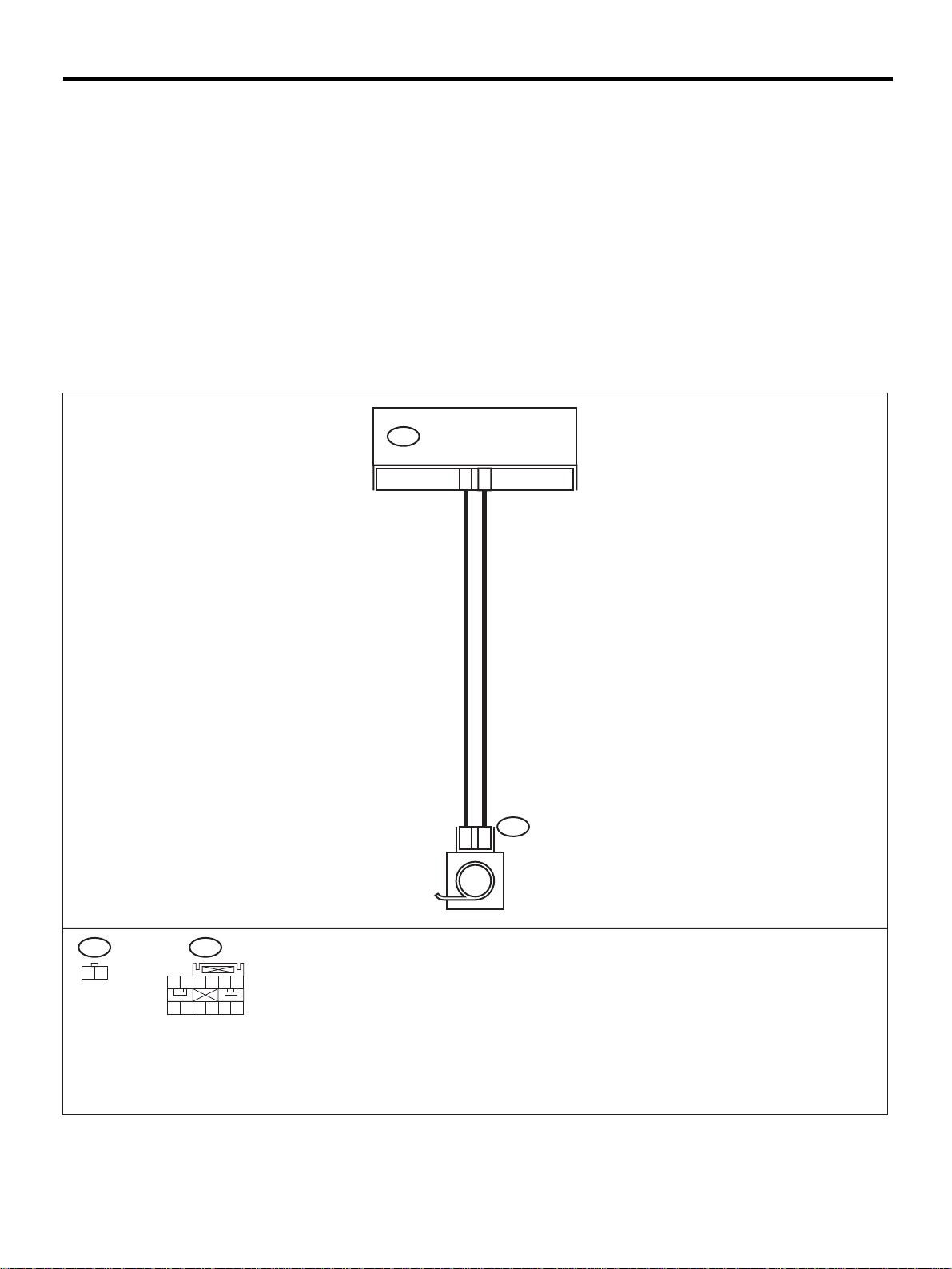
DIAGNOSTIC CHART WITH DIAGNOSTIC TROUBLE CODE (DTC)
AIRBAG SYSTEM (DIAGNOSTICS)
U: DTC 61
DIAGNOSIS:
• Seat belt pretensioner (RH) circuit is open, shorted or shorted to ground.
• Airbag control module is faulty.
• Pretensioner is faulty.
• Pretensioner harness is faulty.
CAUTION:
• Before diagnosing the airbag system, be sure to turn the ignition switch OFF, disconnect the
ground cable from the battery, and wait more than 20 seconds before starting to work.
• Before replacing the airbag module, roll connector, control module, and sensor, reconnect each
part and confirm that the warning light operates properly.
• When inspecting the side airbag harness, disconnect the side airbag module connector and seat
belt pretensioner connector for the safety reasons.
WIRING DIAGRAM:
AIRBAG CONTROL MODULEAB18
6
5
AB26 AB18
1 2
1 2 3
7 8 9
4 5 6
10 11 12
AB26
1
2
PRETENSIONER RH
AB-70
AB-00301
Page 73

DIAGNOSTIC CHART WITH DIAGNOSTIC TROUBLE CODE (DTC)
Step Value Yes No
1 CHECK SEAT BELT PRETENSIONER.
1) Turn the ignition switch OFF, disconnect
the battery ground cable, and wait more
than 20 seconds.
2) Disconnect the connector (AB26) from the
seat belt pretensioner (RH ). <Ref. to SB-7,
Front Seat Belt.>
3) Connect the connector (1F) in test harness
F to (AB26).
4) Connect the airbag resistor to connector
(3F) in test harness F.
5) Connect the battery ground cable and turn
the ignition switch ON.
Does the airbag warning light operate properly?
2 CHECK SIDE AIRBAG HARNESS (RH).
1) Turn the ignition switch OFF, disconnect
the battery ground cable, and wait more
than 20 seconds.
2) Disconnect the airbag resistor from the test
harness.
3) Disconnect the connector (AB25) from
(AB24).
4) Disconnect the connectors (AB17) and
(AB18) from the airbag control module.
<Ref. to AB-17, Airbag Control Module.>
5) Connect the connector (1I) in test harness
I2 to connector (AB18).
6) Measure the resista nce betw een connec tor
(3I) in test harness I2 and co nnect or (3F) i n
test harness F.
Connector & terminal
(3I) No. 8 — (3F) No. 4:
(3I) No. 6 — (3F) No. 3:
Is the measured value less than the specified value?
3 CHECK SIDE AIRBAG HARNESS (RH).
Measure the resistance of th e conne ctor (3I) in
test harness I2.
Connector & terminal
(3I) No. 6 — No. 8:
Does the measured v alue exceed t he speci fied
value?
4 CHECK SIDE AIRBAG HARNESS (RH).
Measure the resistance between connector
(3I) in test harness I2 and the chassis ground.
Connector & terminal
(3I) No. 6 — Chassis ground:
(3I) No. 8 — Chassis ground:
Does the measured v alue exceed t he speci fied
value?
AIRBAG SYSTEM (DIAGNOSTICS)
Operates properly. Replace seat belt
pretensioner (RH).
<Ref. to SB-7,
Front Seat Belt.>
10 Ω Go to step 3. Replace side air-
1 MΩ Go to step 4. Replace side air-
1 MΩ Replace the airbag
control module.
<Ref. to AB-17,
Airbag Control
Module.>
Go to step 2.
bag harness.
<Ref. to AB-16,
Side Airbag Harness.>
bag harness.
<Ref. to AB-16,
Side Airbag Harness.>
Replace side airbag harness.
<Ref. to AB-16,
Side Airbag Harness.>
AB-71
Page 74
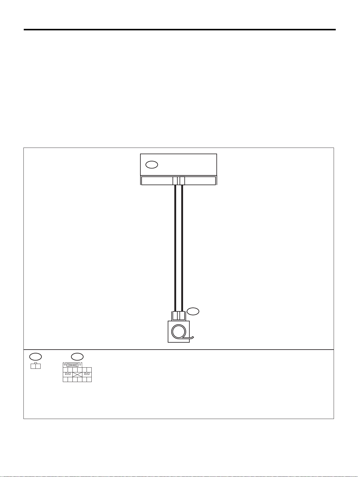
DIAGNOSTIC CHART WITH DIAGNOSTIC TROUBLE CODE (DTC)
AIRBAG SYSTEM (DIAGNOSTICS)
V: DTC 62
DIAGNOSIS:
• Seat belt pretensioner (LH) circuit is open, shorted or shorted to ground.
• Airbag control module is faulty.
• Pretensioner is faulty.
• Pretensioner harness is faulty.
CAUTION:
• Before diagnosing the airbag system, be sure to turn the ignition switch OFF, disconnect the
ground cable from the battery, and wait more than 20 seconds before starting to work.
• Before replacing the airbag module, roll connector, control module, and sensor, reconnect each
part and confirm that the warning light operates properly.
• When inspecting the side airbag harness, disconnect the side airbag module connector and seat
belt pretensioner connector for the safety reasons.
WIRING DIAGRAM:
AIRBAG CONTROL MODULEAB17
1
2
AB21
1 2
1 2 3
7 8 9
AB17
4 5 6
10 11 12
AB21
1
2
PRETENSIONER LH
AB-72
AB-00302
Page 75

DIAGNOSTIC CHART WITH DIAGNOSTIC TROUBLE CODE (DTC)
Step Value Yes No
1 CHECK SEAT BELT PRETENSIONER.
1) Turn the ignition switch OFF, disconnect
the battery ground cable, and wait more
than 20 seconds.
2) Disconnect the connector (AB21) from the
seatbelt pretensioner (LH). <Ref. to SB-7,
Front Seat Belt.>
3) Connect the connecto r (1F) in t est harnes s
F to (AB21).
4) Connect the airbag resistor to the connector (3F) in test harness F.
5) Connect the battery ground cable and turn
the ignition switch ON.
Does the airbag warning light operate properly?
2 CHECK SIDE AIRBAG HARNESS (LH).
1) Turn the ignition switch OFF, disconnect
the battery ground cable, and wait more
than 20 seconds.
2) Disconnect the airbag resistor from the test
harness.
3) Disconnect the connector (AB20) from
(AB19).
4) Disconnect the connectors (AB17) and
(AB18) from the airbag control module.
<Ref. to AB-17, Airbag Control Module.>
5) Connect the connector (1I) in test harness
I2 to the connector (AB17).
6) Measure the resista nce betw een connec tor
(3I) in test harness I2 and the connector
(3F) in test harness F.
Connector & terminal
(3I) No. 11 — (3F) No. 4:
(3I) No. 13 — (3F) No. 3:
Is the measured value less than the specified value?
3 CHECK SIDE AIRBAG HARNESS (LH).
Measure the resistance of th e conne ctor (3I) in
test harness I2.
Connector & terminal
(3I) No. 11 — No. 13:
Does the measured v alue exceed t he speci fied
value?
4 CHECK SIDE AIRBAG HARNESS (LH).
Measure the resistance between the connector (3I) in test harness I2 and the chassis
ground.
Connector & terminal
(3I) No. 11 — Chassis ground:
(3I) No. 13 — Chassis ground:
Does the measured v alue exceed t he speci fied
value?
AIRBAG SYSTEM (DIAGNOSTICS)
Operates properly. Replace seat belt
pretensioner (LH).
<Ref. to SB-7,
Front Seat Belt.>
10 Ω Go to step 3. Replace side air-
1 MΩ Go to step 4. Replace side air-
1 MΩ Replace the airbag
control module.
<Ref. to AB-17,
Airbag Control
Module.>
Go to step 2.
bag harness.
<Ref. to AB-16,
Side Airbag Harness.>
bag harness.
<Ref. to AB-16,
Side Airbag Harness.>
Replace side airbag harness.
<Ref. to AB-16,
Side Airbag Harness.>
AB-73
Page 76
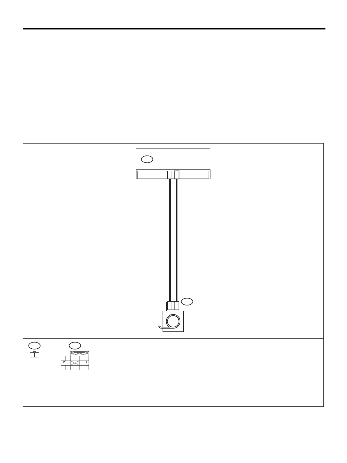
DIAGNOSTIC CHART WITH DIAGNOSTIC TROUBLE CODE (DTC)
AIRBAG SYSTEM (DIAGNOSTICS)
W: DTC 65
DIAGNOSIS:
• Seat belt pretensioner (RH) circuit is shorted to the power supply.
• Pretensioner is faulty.
• Pretensioner harness is faulty.
• Airbag control module is faulty.
CAUTION:
• Before diagnosing the airbag system, be sure to turn the ignition switch OFF, disconnect the
ground cable from the battery, and wait more than 20 seconds before starting to work.
• Before replacing the airbag module, roll connector, control module, and sensor, reconnect each
part and confirm that the warning light operates properly.
• When inspecting the side airbag harness, disconnect the side airbag module connector and seat
belt pretensioner connector for the safety reasons.
WIRING DIAGRAM:
AIRBAG CONTROL MODULEAB18
6
5
AB26 AB18
1 2
1 2 3
7 8 9
4 5 6
10 11 12
AB26
1
2
PRETENSIONER RH
AB-74
AB-00301
Page 77

DIAGNOSTIC CHART WITH DIAGNOSTIC TROUBLE CODE (DTC)
Step Value Yes No
1 CHECK SEAT BELT PRETENSIONER.
1) Turn the ignition switch OFF, disconnect
the battery ground cable, and wait more
than 20 seconds.
2) Disconnect the connector (AB26) from the
seat belt pretensioner (RH ). <Ref. to SB-7,
Front Seat Belt.>
3) Connect the connector (1F) in test harness
F to (AB26).
4) Connect the airbag resistor to connector
(3F) in test harness F.
5) Connect the battery gro und ca ble , an d turn
the ignition switch ON.
Does the airbag warning light operate properly?
2 CHECK SIDE AIRBAG HARNESS (RH).
1) Turn the ignition switch OFF, disconnect
the battery ground cable, and wait more
than 20 seconds.
2) Disconnect the airbag resistor from the test
harness.
3) Disconnect the connector (AB25) from
(AB24).
4) Disconnect the connectors (AB17) and
(AB18) from the airbag control module.
<Ref. to AB-17, Airbag Control Module.>
5) Connect the connector (1I) in test harness
I2 to the connector (AB18).
6) Connect the battery ground cable and turn
the ignition switch ON.
7) Measure the voltage between connector
(3I) in test harness I2 and the chassis
ground.
Connector & terminal
(3I) No. 6 (+) — Chassis ground (
(3I) No. 8 (+) — Chassis ground (
Is the measured value less than the specified value?
−−−−
−−−−
AIRBAG SYSTEM (DIAGNOSTICS)
Operates properly. Replace seat belt
pretensioner (RH).
<Ref. to SB-7,
Front Seat Belt.>
1 V Replace the airbag
control module.
<Ref. to AB-17,
Airbag Control
Module.>
):
):
Go to step 2.
Replace side airbag harness.
<Ref. to AB-16,
Side Airbag Harness.>
AB-75
Page 78
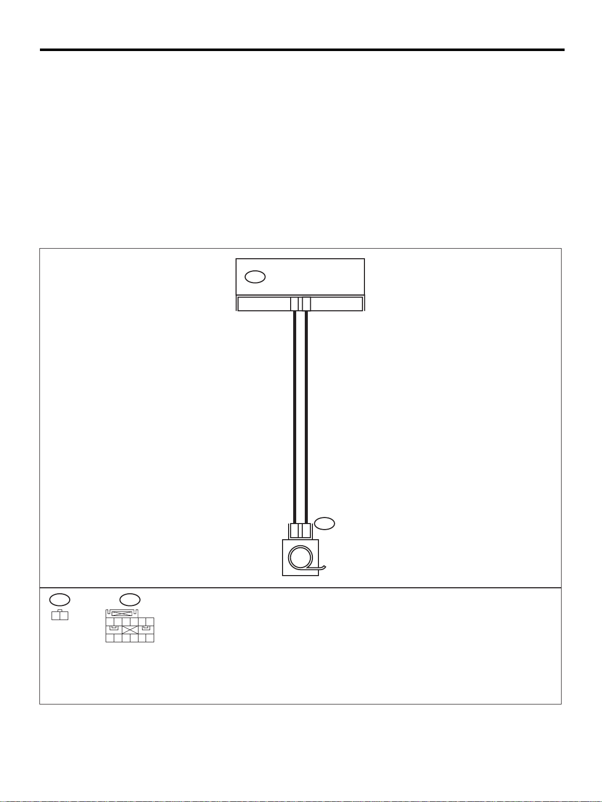
DIAGNOSTIC CHART WITH DIAGNOSTIC TROUBLE CODE (DTC)
AIRBAG SYSTEM (DIAGNOSTICS)
X: DTC 66
DIAGNOSIS:
• Seat belt pretensioner (LH) circuit i s shorted to the power supply.
• Pretensioner is faulty.
• Pretensioner harness is faulty.
• Airbag control module is faulty.
CAUTION:
• Before diagnosing the airbag system, be sure to turn the ignition switch OFF, disconnect the
ground cable from the battery, and wait more than 20 seconds before starting to work.
• Before replacing the airbag module, roll connector, control module and the sensor, reconnect each
part and confirm that the warning light operates properly.
• When inspecting the side airbag harness, disconnect the side airbag module connector and seat
belt pretensioner connector for the safety reasons.
WIRING DIAGRAM:
AIRBAG CONTROL MODULEAB17
1
2
AB21
1 2
1 2 3
7 8 9
AB17
4 5 6
10 11 12
AB21
1
2
PRETENSIONER LH
AB-76
AB-00302
Page 79

DIAGNOSTIC CHART WITH DIAGNOSTIC TROUBLE CODE (DTC)
Step Value Yes No
1 CHECK SEAT BELT PRETENSIONER.
1) Turn the ignition switch OFF, disconnect
the battery ground cable, and wait more
than 20 seconds.
2) Disconnect the connector (AB21) from the
seat belt pretensioner (LH) . <Ref. to SB-7,
Front Seat Belt.>
3) Connect the connector (1F) in test harness
F to (AB21).
4) Connect the airbag resistor to the connector (3F) in test harness F.
5) Connect the battery ground cable and turn
the ignition switch ON.
Does the airbag warning light operate properly?
2 CHECK SIDE AIRBAG HARNESS (LH).
1) Turn the ignition switch OFF, disconnect
the battery ground cable, and wait more
than 20 seconds.
2) Disconnect the airbag resistor from the test
harness.
3) Disconnect the connector (AB20) from
(AB19).
4) Disconnect the connectors (AB17) and
(AB18) from the airbag control module.
<Ref. to AB-17, Airbag Control Module.>
5) Connect the connector (1I) in test harness
I2 to the connector (AB17).
6) Connect the battery ground cable and turn
the ignition switch ON.
7) Measure the voltage between connector
(3I) in test harness I2 and the chassis
ground.
Connector & terminal
(3I) No. 11 (+) — Chassis ground (
(3I) No. 13 (+) — Chassis ground (
Is the measured value less than the specified value?
AIRBAG SYSTEM (DIAGNOSTICS)
Operates properly. Replace seat belt
pre-tensioner (LH).
<Ref. to SB-7,
Front Seat Belt.>
1 V Replace the airbag
control module.
<Ref. to AB-17,
Airbag Control
Module.>
−−−−
):
−−−−
):
Go to step 2.
Replace side airbag harness.
<Ref. to AB-16,
Side Airbag Harness.>
AB-77
Page 80

DIAGNOSTIC CHART WITH DIAGNOSTIC TROUBLE CODE (DTC)
AIRBAG SYSTEM (DIAGNOSTICS)
MEMO:
AB-78
 Loading...