

Page 1
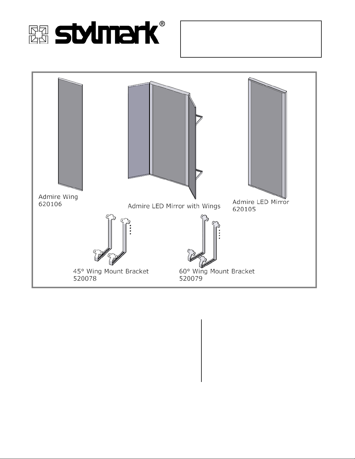
Installation Instructions
Admire LED Mirror
Model: 620105
INSTALLATION INSTRUCTIONS
Please read these instructions carefully before beginning installation.
Tools you’ll need
Figure 1
Before you begin
These instructions i l lustrate the Stylmark® Admire LED
Mirror. If you have questions during assembly, call 800328-2495 to request technical assistance. This
installation recommends two people to install.
• Level
• Tape measure
• Drill and bits
• #2 Phillips screwdriver
• 75 lbs. pullout rated fasteners
• Wiring tools
• Vacuum glass cups
Stylmark, Incorporated ♦ 6536 Main Street NE, PO Box 32008 ♦Minneapolis, MN 55432
1-800-328-2495 ♦www.stylmark.com
Sheet# 971826
Revision C (1/17)
Page 2
Stylmark Installation Instructions: Admire LED Mirror
Getting Started:
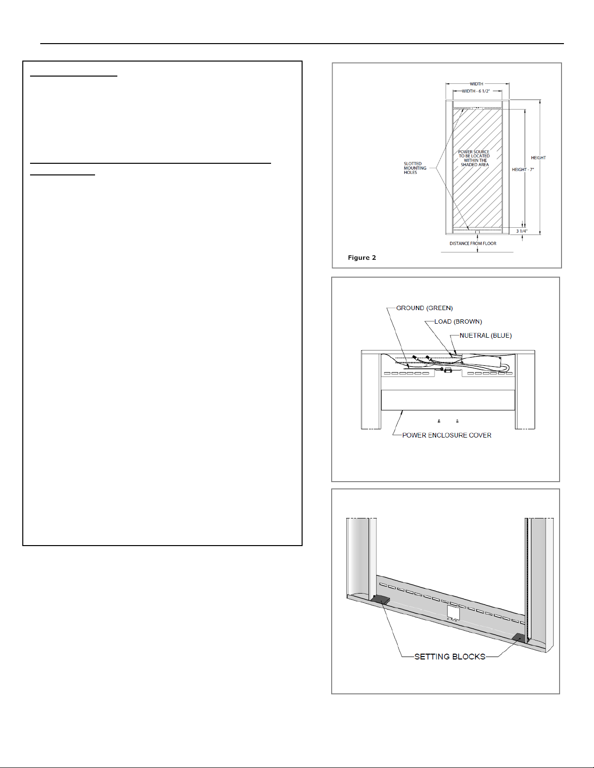
Figure 3
Figure 4
Please revie w t he important safety i nst ructions
before starting. Installation sh ould be performed by
authorized pers onnel only. This mi r ror is for
commercial use only, intended as a vi ewing mirror.
Step-by-Step Instructions – With Hardwired
Connection:
1. Remove the product from the box and put the mirror
and setting blocks aside.
2. Determine moun ting location. Loca tion must have
power source location on the wall within the inner
area of the fixture. The fixture include s s lotted
mounting holes located in the top and bottom of the
fixture. The distance from floor is to be d e termined
by customer. Stylmark recommends th is d is ta nce to
be a minimum of 8”. See Figure 2
3. Fasten mirror fr ame to wall studs or suita b le
structural location through slott ed mounting holes in
both the top and bottom of the frame. Us e fastening
screws with a m inimum pullout rating of 75lb s p er
fastener (obtain loc ally).
Note: Fixture must be level & plumb.
4. Once metal frame is securely attached to wall,
remove the power enclosure cover and connect all
wiring per applicable local c odes . See Figure 3
When finished, replace the power enclosure cover.
5. Position the sett ing blocks on the lower ed ge of the
frame. See Figure 4
6. Using vacuum glass cups, install the mirror by lifting
it up into the top ch a nnel, then down into the lower
channel and onto the setting blocks. See Figure 5
Stylmark, Incorporated ♦ 6536 Main Street NE, PO Box 32008 ♦Minneapolis, MN 55432
1-800-328-2495 ♦www.stylmark.com
Sheet# 971826
Revision C (1/17)
Page 3
Step-by-Step Instructions – With Plug-in
Stylmark Installation Instructions: Admire LED Mirror
Figure 5
Figure 7
Figure 8
power cord
1. Remove the product from the box a nd put the
mirror and setting blocks aside.
2. Determine moun ting location. Loca tion must have
a standard 115V 15 amp outlet located within the
inner area of th e fixture or within 12” from the
bottom center of th e m ir ror frame. The fixture
includes slotted mounting holes located in the top
and bottom of the fixture. The distanc e from the
floor is to be determined by customer. Stylmark
recommends this dis tance to be a minimum of 8”.
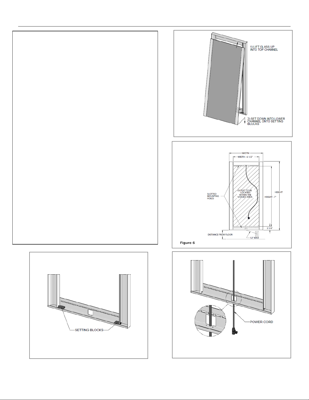
See Figure 6
3. Fasten mirror fr ame to wall studs or suita b le
structural location through slotted mounting holes
in both the top and bottom of the frame ( if outlet
is located outside of the frame, feed cord through
the “mouse hole” b efore securing to the w all).
See Figure 7
Use fastening s c r e ws with a minimum pullout
rating of 75lbs per f a s te ner (obtain locally).
Note: Fixture must be level & plumb.
4. Once metal frame is s e c urely attached to the wall,
plug the cord into the outlet.
5. Position settin g b loc ks on the lower edge of the
frame. See Figure 8
6. Using vacuum glass cups, install the mirror by
lifting it up into th e top channel, then d own into
the lower channel and onto the setting bloc ks.
See Figure 9
Stylmark, Incorporated ♦ 6536 Main Street NE, PO Box 32008 ♦Minneapolis, MN 55432
1-800-328-2495 ♦www.stylmark.com
Sheet# 971826
Revision C (1/17)
Page 4
Step-by-Step Instructions – Wall Cleat Kit
Stylmark Installation Instructions: Admire LED Mirror
Figure 9
Figure 11
Figure 12
Part #520075 (order separately)
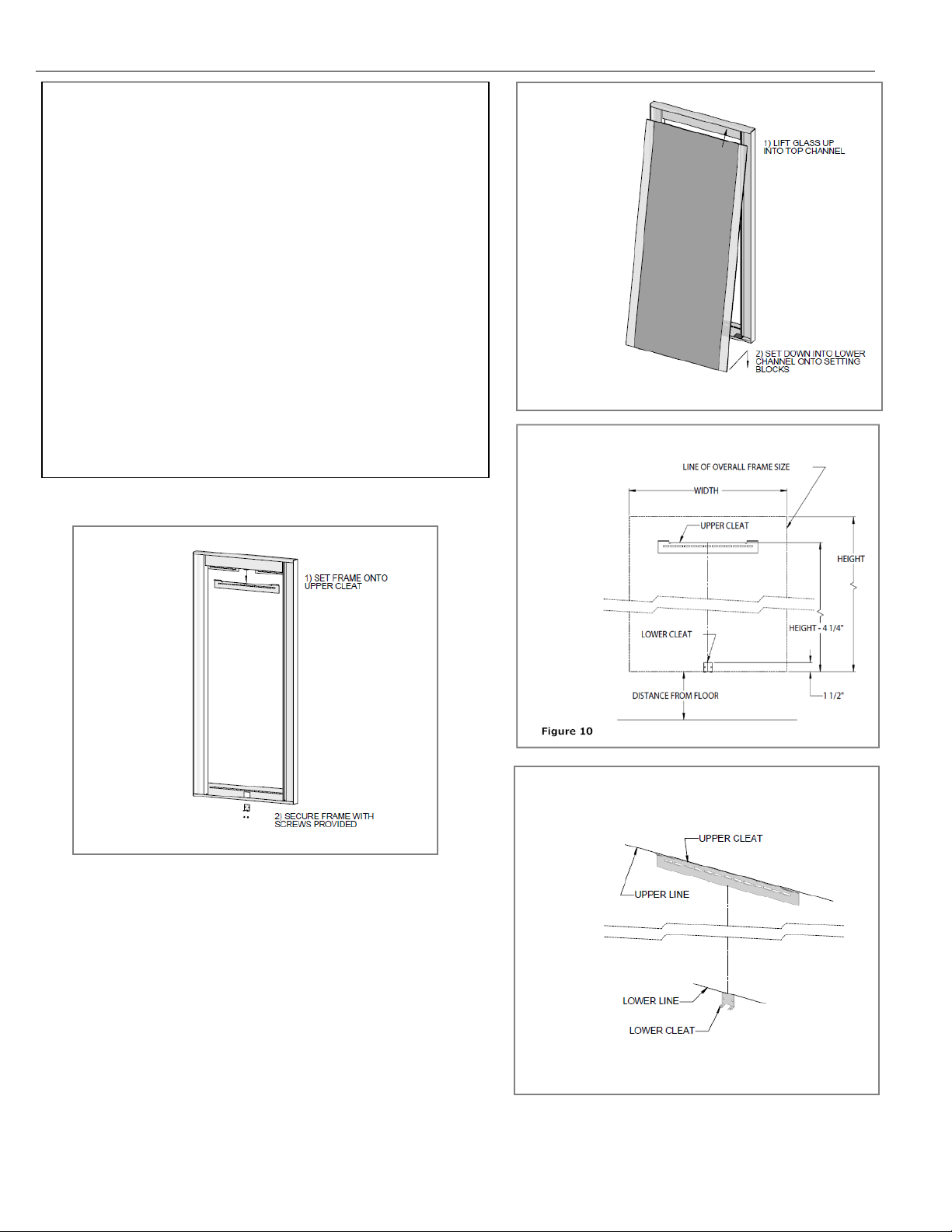
1. Refer to Figure 10 f or the mounting locations of the
upper and lower cleats. Ma r k a level line at these
locations.
See Figure 10
2. Fasten the upper a nd lower cleats to the wall or
suitable structu r a l location with the top edge of the
part on the lines f r om step 1. See Figure 1
Use fastening screws with a minimum pullout rating
of 75lbs per fasten er (obtain locally).
Note: Cleats must be level and plumb
3. Set frame onto upper cleat and secure frame to lower
cleat with screws p r ovided. See Figure 12
Stylmark, Incorporated ♦ 6536 Main Street NE, PO Box 32008 ♦Minneapolis, MN 55432
1-800-328-2495 ♦www.stylmark.com
Sheet# 971826
Revision C (1/17)
Page 5
Stylmark Installation Instructions: Admire LED Mirror
Step-by-Step Instructions – Wings
Figure 15
Figure 14
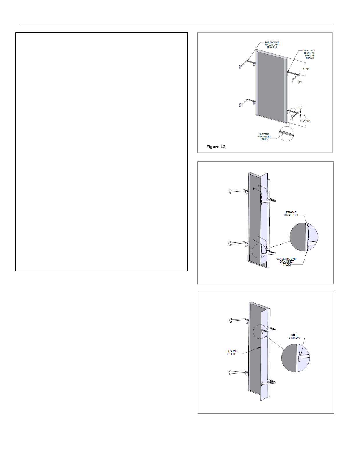
1. With Admire Mirror pre-installed, measure down f rom
the top surface of the Admire Mirror making one
small pencil location mark at 12-7/8”. Then measure
up from the bottom edge and m a k e a m a rk a t 1129/32”. Using a carpenter’s square, draw a
perpendicular line from th e s ide of the Admire Mirror
at each of the pen cil location marks. Note: the
perpendicular line will be used for lining up th e top
edge of the wall mount brackets. See Figure 13
2. Locate the top edge of the wall mount br a cket flush
with the perpendicular lines and f lus h to the side of
the Admire Mirror. Once located, fasten each wall
mount bracket through the slotted mounting h oles
using fasteners with a minimum pullout rating of
75lbs per fastener (obtain locally).
See Figure 13
3. With the wall moun t b r a ckets securely fastened in
place, carefu lly lift and lower the mirr or wing onto the
wall mount brackets making su re it is flush with the
four wall moun t b r a cket tabs and in line with the four
frame brackets. See Figure 14
4. On c e the mirror wings are in place on the wall mount
bracket, to minimize the gap between th e m irror and
the wing and to secure the win g in pla c e, gently push
the wing frame edge towards th e pre-installed Admire
Mirror. With slight pressure applied to th e wing
frame edge, fasten the set s c rews through the frame
bracket and into the wall mount brack et tabs.
See Figure 15
Stylmark, Incorporated ♦ 6536 Main Street NE, PO Box 32008 ♦Minneapolis, MN 55432
1-800-328-2495 ♦www.stylmark.com
Sheet# 971826
Revision C (1/17)
Page 6

W
Stylmark Installation Instructions: Admire LED Mirror
IMPORTANT SAFETY INSTRUCTIONS
Step-by-Step Instructions – Cleaning:
Step-by-Step Instructions – Power Supply Repla cem ent:
Step-by-Step Instructions – LED Replacement
1. Turn off power to m ir r or.
2. Use vacuum glass cups to remove mirror fr om fixture by liftin g up and swinging the bottom of the mirror ou t of
the frame and set the glass aside.
3. To replace the power supply, proceed by removing the power enclosu r e c ov er , dis c onnect the power supply from
the high voltage side , then the low voltag e side.
4. Remove and replace the power s upply and make all electrical connections.
Note: Polarity mu st be followed
5. Replace power enclosure cover and mirror.
1. Turn off power to m ir r or.
2. Use vacuum glass cups to remove mirror fr om fixture by liftin g up and swinging the bottom of the mirror out of
the frame and set the glass aside.
3. To replace the LED strip, proceed by removing the power enclosur e c ov er a nd disconnect the low voltage side
from the power supply.
4. The LED strips ar e attached to a magnetic str ip. Simply peel from the fixture and pu ll the wire through the
grommet.
5. Position the new strip so that it is agains t the front lip of the f ixture. Next, feed the wir e through the grommet
and reconnect to the power s upply.
Note: Polarity mu st be followed.
6. Replace power enclosure cover and mirror.
SAVE THESE INSTRUCTIONS
A) READ ALL INSTRUCTIONS BEFORE USING THIS PRODUCT
DANGER - TO REDUCE THE RISK OF ELECTRICAL SHOCK: CONNECT THIS FURNISHING TO A PROPERLY GROUNDED
B)
CIRCUIT
C)
WARNING – TO REDUCE THE RISK OF BURNS, FIRE, ELECTRICAL SHOCK OR INJURY TO PERSON:
a. UNPLUG OR SWITCH OFF POWER BEFORE REMOVING OR REINSTALLING ANY PARTS.
b. USE THIS PRODUCT FOR ITS INTENDED PURPOSE AS DESCRIBED IN THESE INSTRUCTIONS. DO NOT USE ANY
ATTACHMENTS NOT RECOMMENDED BY THE MANUFACTURER.
c. DO NOT CLEAN BY SPRAYING CLEANERS DIRECTLY ON OR NEAR THE LAMPS OF ITS ELECTRICAL CONNECTIONS NEAR THE
REAR OF THE PRODUCT
d. DO NOT ALLOW SPILLED LIQUID TO FALL INTO THE LAMP AREA OR THE CONNECTION BOX AT THE REAR OF THE PRODUCT
e. DO NOT USE OUTDOORS
f. ALWAYS DISABLE POWER TO THIS PRODUCT PRIOR TO SERVICING.
D) RISK OF INJURY – KEEP CHILDREN FROM CLIMBING ON THIS DISPLAY
E) GROUNDING INSTRUCTIONS - THIS PRODUCT MUST BE CONNECTED TO A GROUNDED METAL, PERMANENT WIRING SYSTEM.
F)
DANGER - IMPROPER CONNECTION OF THE EQUIPMENT GROUNDING CONDUCTOR CAN RESULT IN RISK OF ELECTRICAL
SHOCK. CHECK WITH QUALIFIED ELECTRICIAN OR SERVICEMAN IF YOU ARE IN DOUBT WHETHER PRODUCT IS CORRECTLY
GROUNDED.
1. Turn off power to m ir r or.
2. Clean mirror with appropriate clean er s before restoring power.
3. Turn on power to mirr or.
Stylmark, Incorporated ♦ 6536 Main Street NE, PO Box 32008 ♦Minneapolis, MN 55432
1-800-328-2495 ♦www.stylmark.com
Sheet# 971826
Revision C (1/17)
 Loading...