

Page 1
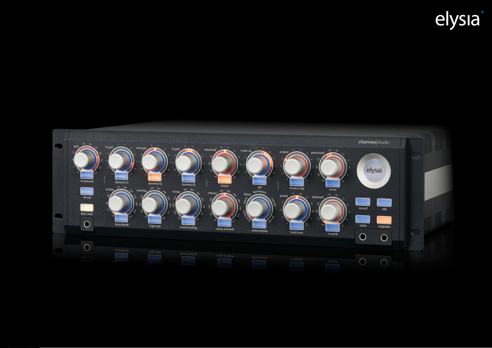
channex|studio
Analog recording. Grown up.
Page 2

channex|studio
Thank you for choosing the channex|studio. It marks the beginning of the seamless integration of our uncompromisingly designed analog audio processors into
modern digital production environments.
Our goal was to create a recording frontend that not only delivers class-A sonic performance, but also meets the demanding requirements of professional recording
studios through exceptional flexibility. Its carefully selected processing modules and zero latency monitoring features make the channex|studio the ideal centerpiece of
any recording chain. At the same time, it excels during the mixing process, allowing previously recorded material to benefit from its full range of analog processing
capabilities. In addition, the channex|studio can be operated completely independently of a computer or DAW. Thanks to its innovative user interface and internal
preset memory, all functions remain fully accessible even in standalone operation. The ability to instantly recall and control every hardware parameter provides a
significant time advantage in today's fast-paced production workflows.
As the channex|studio is built around a fully analog, class-A circuit design, we recommend allowing the unit to warm up for approximately 15 to 20 minutes before
each session. This ensures that all components reach a stable operating condition, providing consistent and fully reproducible performance.
table of content
elysia shell element 1
preamp 2
equalizer 3
equalizer (dynamic) 4
equalizer (Q factor) 5
equalizer (setup ⚙) 6
table of content
hardware insert 7
routing 8
dynamic section (compressor) 9
dynamic section (limiter) 10
dynamic section (setup ⚙) 11
avor 12
preset 13
output 14
monitor section 15
monitor section (artist) 16
monitor section (engineer) 17
monitor section (setup ⚙) 18
connections (left) 19
connections (right) 20
software 21
Page 3
shell element
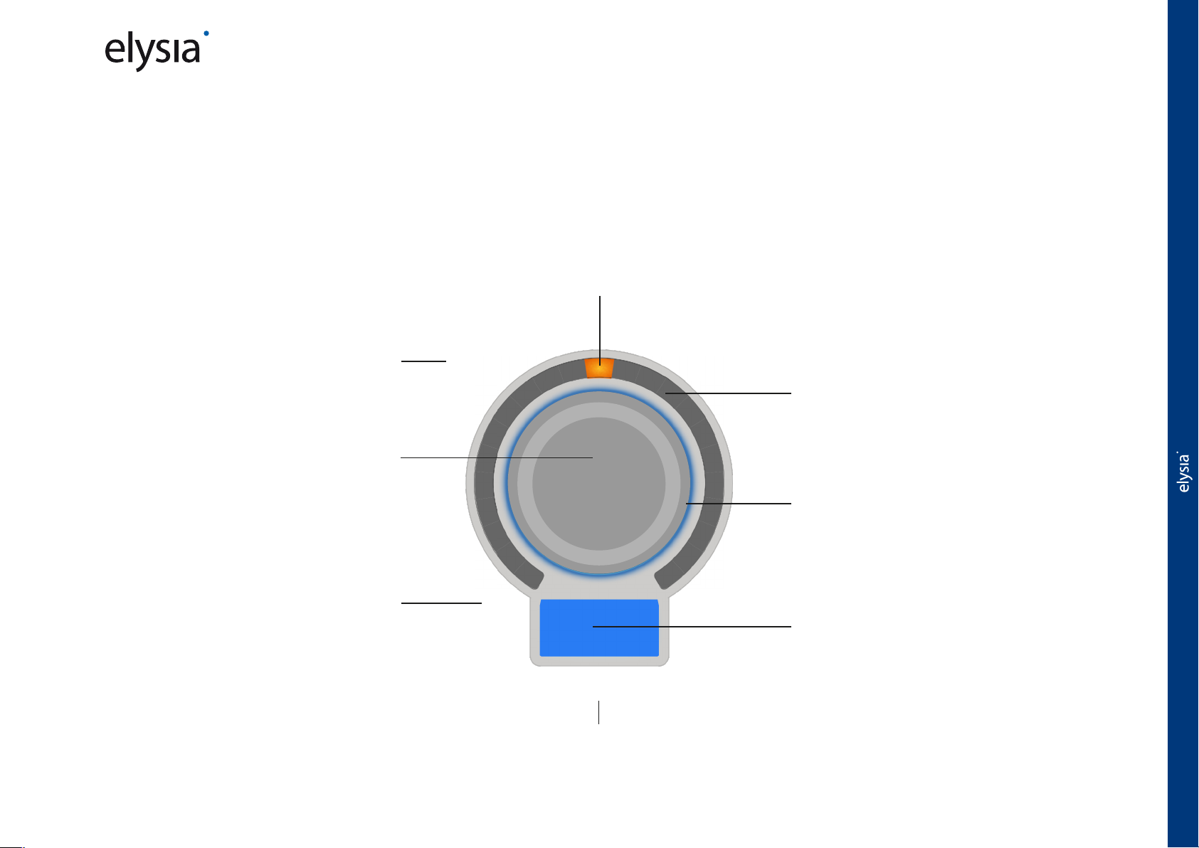
The shell is the heart of the channex|studio user interface and the result of our pursuit of an intuitive control concept that provides instant access to every function of
the unit. It allows you to adjust all settings, edit parameters, read values and access other menu levels via the multifunction button.
The tactile feel and precision of the controls meet the high standards expected from an elysia analog processor. The arch LED element is capable of displaying a wide
range of static and dynamic information. In addition, the multi-color illumination of the rotary controls, as well as the illuminated multifunction buttons, provides clear
visual feedback on control linkings, parameter assignments and the status of various functions.
As a result the shell is far more than just an input device. It also serves as a highly efficient visual interface, allowing you to grasp all relevant information at a glance.
value indicator
This indicator marks the currently set value.
shell function name
Identifies the primary function assigned to the
control. In the plugin, this label changes according
to the selected function, helping the user navigate
and identify the current assignment.
shell controller
Allows adjustment of function-specific
parameters. Thanks to the flexibility of the arch
LED element, the control can operate either in
discrete steps or continuously, depending on the
selected function.
shell function scaling
Scales the values associated with the respective
control. In the plugin, this scale changes
according to the selected function, helping the
user interpret and adjust the corresponding
parameters more effectively.
3
4
4
0
4
arch LED element
Some parameters also display additional dynamic
information, such as compressor gain reduction or lter Q.
6
gain
4
1
2
8
float illumination
6
2
5
2
5
4
8
6
-
0
1
-
Multicolor indication of additional settings status.
Secondary functions or associated controls can
illuminate in the same color to indicate that they
belong together. Orange or red illumination indicates
an alternate function layer, while ashing red indicates
clipping.
select button
Used to enable and disable functions and provides
access to the second and third function layers.
hi pass/pol
secondary function, long push function
The secondary function and additional function layers (if available) are labeled here.
shell element
1
Page 4
preamp
preamp
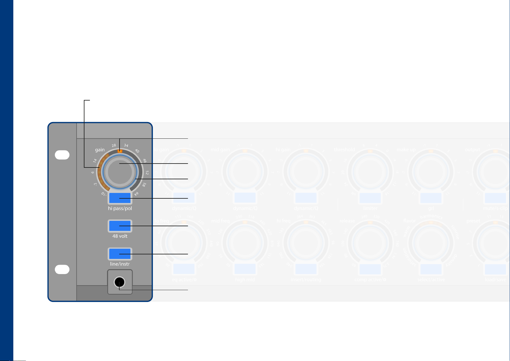
The channex|studio features a fully discrete class-A microphone preamplifier with up to 64 dB of gain. Since the adjustable gain range starts at –10 dB, no input pad is
required. The gain settings for the three physical input types, mic, line and instrument are stored individually and are automatically recalled, even after the unit has been
disconnected from the power supply. The preamplifier is equipped with a continuously variable high-pass filter, switchable polarity and 48 V phantom power for the
microphone input.
input signal metering
Displays the level of the signal present at the selected input. The meter is tapped after the preamp to allow proper gain staging to the
optimal operating level of the channex|studio (0–16 dBu). Optionally, the plugin can display the signal level in dBu. Any clipping is indicated
by red float illumination.
gain indicator
Indicates the selected gain in dB.
preamp gain
This control is used to adjust the gain of the currently selected source.
clipping indicator
The float illumination indicates input signal clipping (red LED).
high pass/polarity selection
A short push of the button switches to the high pass filter display and adjustment mode (orange LED)
and back again. A long press changes the polarity of the input signal (blue LED).
phantom power (+48V)
Pressing and holding the button activates or deactivates phantom power for the microphone input. During
switching the audio path is muted. Note: Phantom power is not being recalled on the first level for safety reasons!
line-/instrument input selection
A short push of this button switches the input source from the microphone input to the line input or vice
versa. Pressing and holding switches to the front instrument input or back again. The respective gain settings
are stored and automatically restored when switching input sources.
instrument input
This is the connection for high impedance instrument sources. This input is also designed to be balanced.
2
Page 5
equalizer
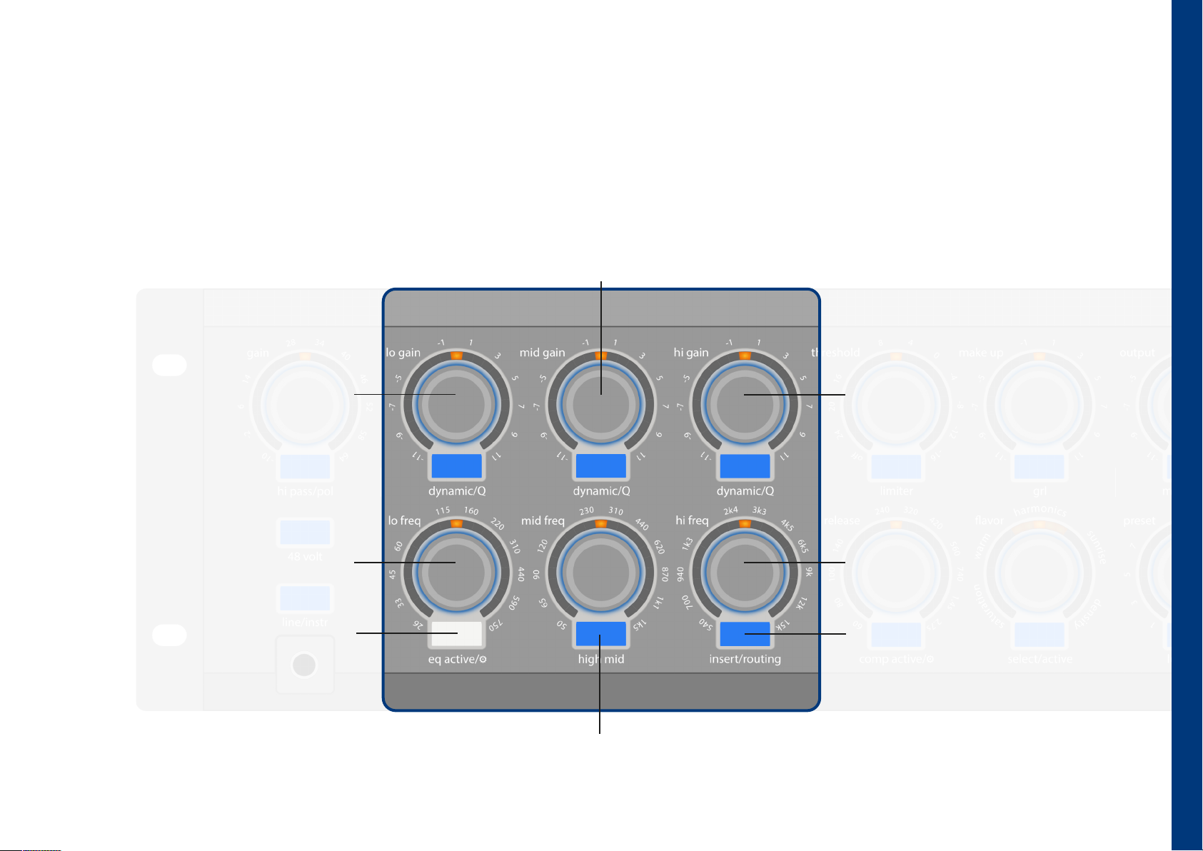
The channex|studio features a 4-band equalizer that allows both static and dynamic boost or cut in every band. The amount of dynamic processing is displayed in real
time on the arch LED element, together with the configured static boost or cut, providing immediate visual feedback on the EQ's behavior. The bandwidth (Q) of all
four bands is continuously variable. The two outer bands can be switched from bell to shelf mode, while each band offers a maximum boost or cut of ±11 dB. The
insert/routing button assigned to the high-frequency band activates the rear-panel hardware insert or provides access to the processor routing menu, where the
order of the individual modules can be configured (page 7).
mid/high mid frequency gain
With this control, boosts and cuts for the two mid bands can be adjusted independently. The float illumination indicates
which band is currently being controlled. The center position has a slight magnetic feel, making it easy to locate again.
This provides a per-band switchable bypass.
low frequency gain
This control adjusts the boost or cut of the low
frequency band. The center position has a
slight magnetic feel, making it easy to locate
again. This provides a per-band switchable
bypass.
low frequency selection
Sets the cutoff frequency of the low
frequency band.
eq active (or bypass)
A short push switches between equalizer
inactive (blue LED) and equalizer active (white
LED). A long push of the button enters the
setup of the equalizer or returns from it.
(page 12)
high frequency gain
This control adjusts the boost or cut of the high
frequency band. The center position has a slight
magnetic feel, making it easy to locate again. This
provides a per-band switchable bypass.
equalizer
high frequency selection
Sets the cutoff frequency of the high
frequency band.
insert/routing (long push)
See hardware insert (page 7) and routing.
(page 8)
high mid band
Switches to the display and adjustment mode for the upper mid band (orange LEDs). Pressing and
holding the button resets all equalizer parameters to their default values.
3
Page 6
equalizer (dynamic)
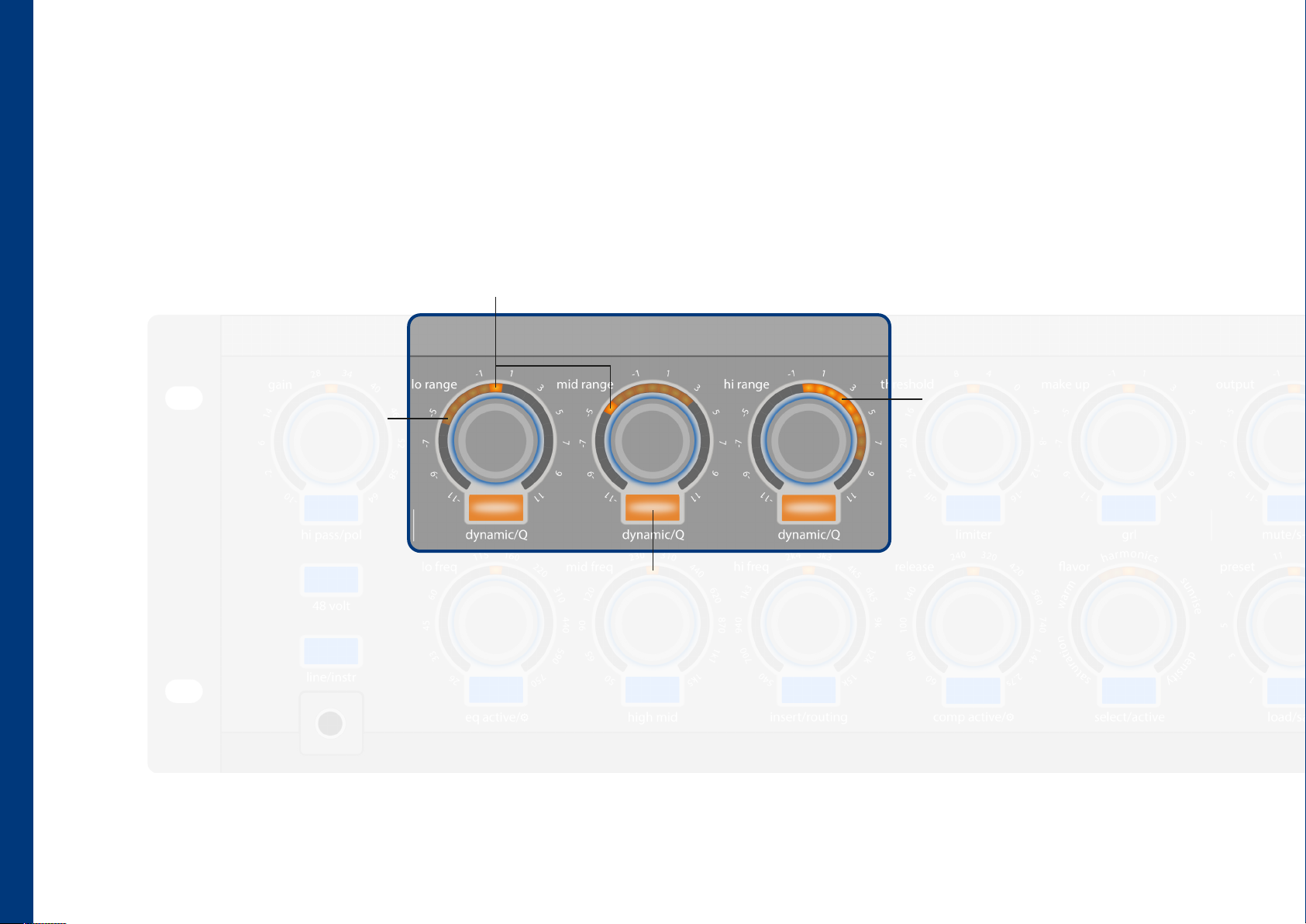
In addition to standard static EQ processing, the channex|studio's fully analog four-band equalizer allows each band to perform dynamic boost or dynamic cut
independently. The dynamic/Q button does not switch an EQ band between static and dynamic modes. Instead, it changes the parameter assigned to the control,
allowing you to adjust the intensity of the dynamic processing. Any static EQ settings remain active, unchanged and continuously displayed. Dynamic processing is
always configured and displayed relative to the existing static EQ setting. This makes it possible, for example, to configure one band as a de-esser that dynamically
attenuates excessive sibilance, while another band dynamically boosts the presence range of a vocal only when additional presence is needed.
gain indicator
Indicates fixed applied boosts and cuts.
metering
This shows the boost or cut resulting from
range
Visualizes the maximum range used for
dynamic boost or attenuation. The unity
position has a slight magnetic feel, making it
easy to locate again and disabeling the
dynamic function.
both static and dynamic processing.
Dynamic processing is displayed relative to
the fixed applied boost or cut position.
equalizer (dynamic)
4
dynamic function per band
A short push switches to the view and adjustment mode for the range of the
dynamic processing for the respective band. Pressing it again briefly switches back to
the view and adjustment mode for the static processing. The high mid button can
also be used to adjust the dynamic processing for the upper mid band.
Page 7
equalizer (Q factor)
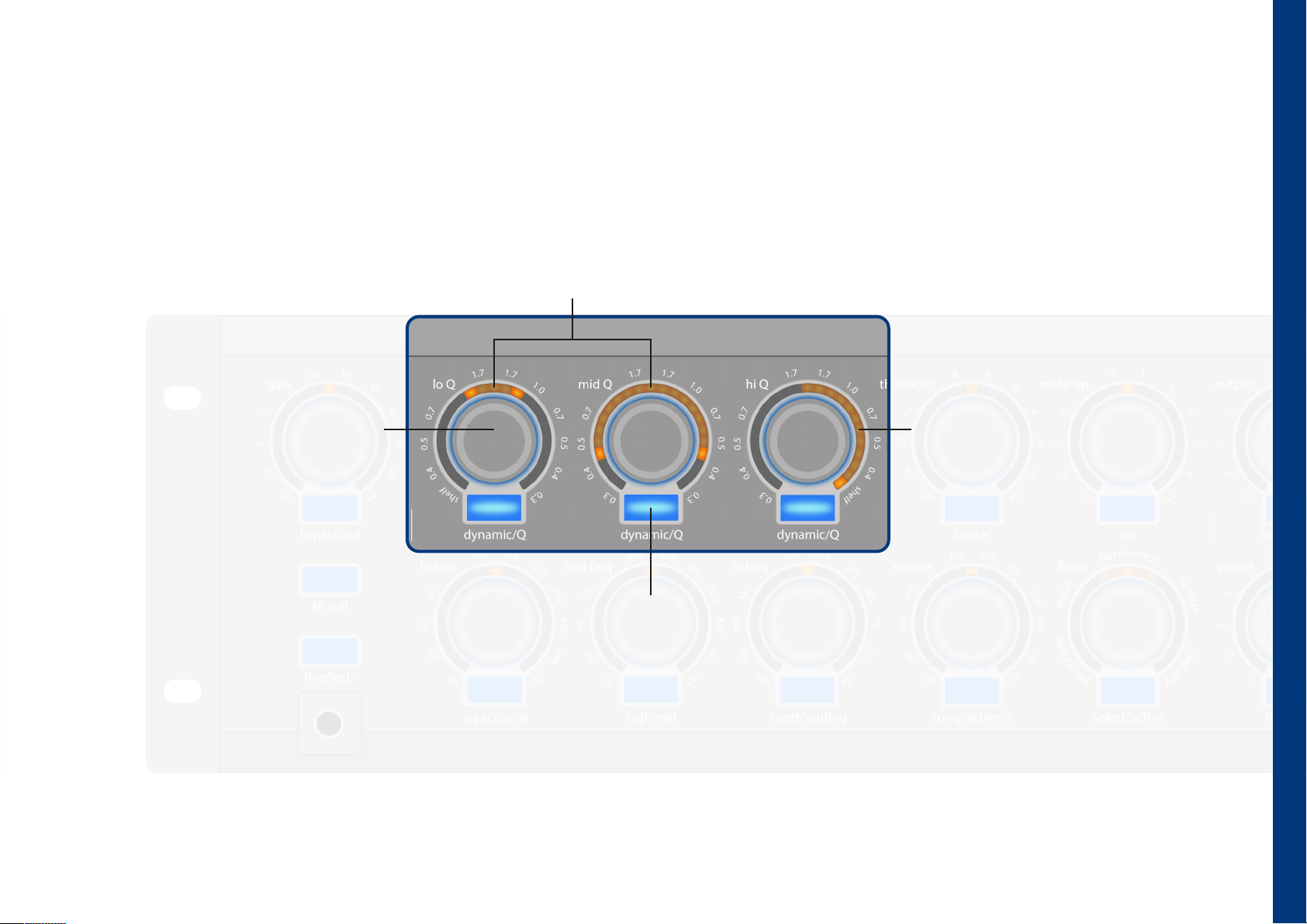
The bandwidth (Q) of each EQ band can be adjusted continuously and independently. Q is controlled using the gain knob of the respective band, while the selected
bandwidth is visualized on the arch LED element. On the two outer bands, increasing the bandwidth setting beyond its maximum bell value automatically changes the
operating mode from bell to shelf.
Q indicator
Represents the bandwidth in the respective bands by means of two
LED segments that are displayed either further apart or closer together.
Q controller
The bandwidth of the filters can be
adjusted using the gain controls of the
individual bands.
shelving filter (hi & lo band)
Adjusting the gain control beyond the
maximum bandwidth switches the
operating mode from bell to shelf. This is
indicated in the arch LED element by an arc
segment pointing to the left (low-shelf ) or
right (high-shelf ).
equalizer (Q factor)
Q function per band (long push)
A long push of the button switches to the view and adjustment
mode for the bandwidth of the respective band and back again.
Adjustment is performed using the gain controls.
5
Page 8
equalizer (setup ⚙)
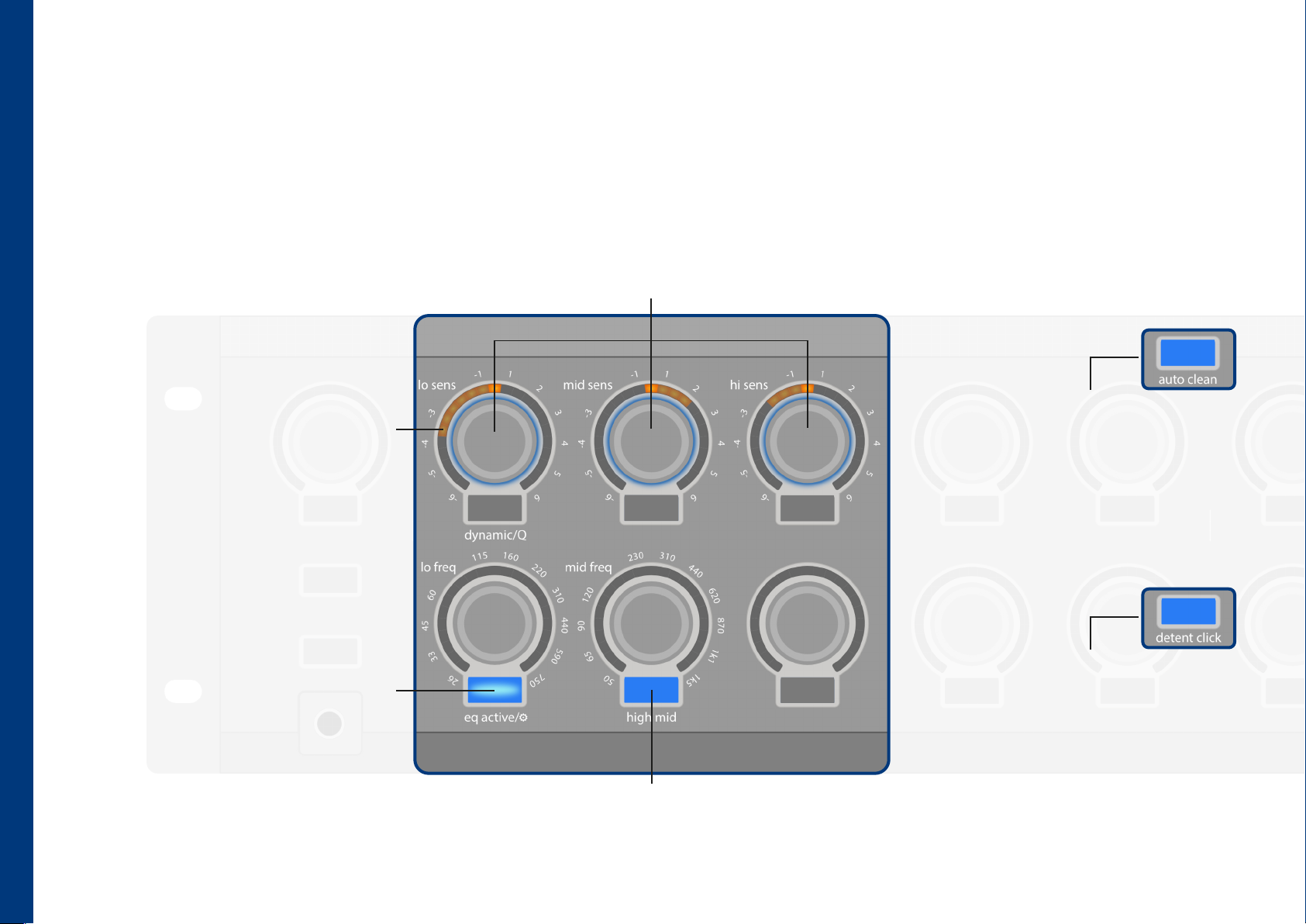
This submenu provides access to advanced settings, including the sensitivity of the dynamic equalizer. It also allows you to define the behavior of the controls and
buttons after extended periods of inactivity, as well as enable or disable the center-position feedback when passing through the unity gain position. The illuminated
record and engineer buttons indicate the current status of these functions. The sensitivity of the dynamic processing can be adjusted independently for each EQ
band.
band dynamic function sensitivity
The sensitivity for dynamic processing can be adjusted per band using the gain controls of the individual frequency bands.
Turning counterclockwise reduces sensitivity, while turning clockwise increases it. The activity of the respective bands is also
visualized in the arch LED element during adjustment.
dynamic function metering
The arch LED element displays the signal level
of the dynamic boost or attenuation within the
band. This allows the sensitivity of the dynamic
EQ bands to be adjusted directly.
equalizer (setup)
equalizer setup (long push)
A long push of the button switches to the
equalizer settings setup or back again.
high mid band selection
Switches to the display and adjustment mode for
the upper mid band (orange LEDs).
auto clean
After 3 seconds of inactivity, the controls
automatically return to the default view. The
auto clean function for the equalizer section
can be activated (red LED) or deactivated
(blue LED) by pressing the record button in
the monitor section.
detent click feedback
This function provides audible feedback for
the magnetic detent. It can be activated
(orange LED) or deactivated (blue LED) by
pressing the engineer button. During
deliberate fast control movements, the click
is ignored and the slight magnetic detent at
the center position is also disabled.
6
Page 9
hardware insert
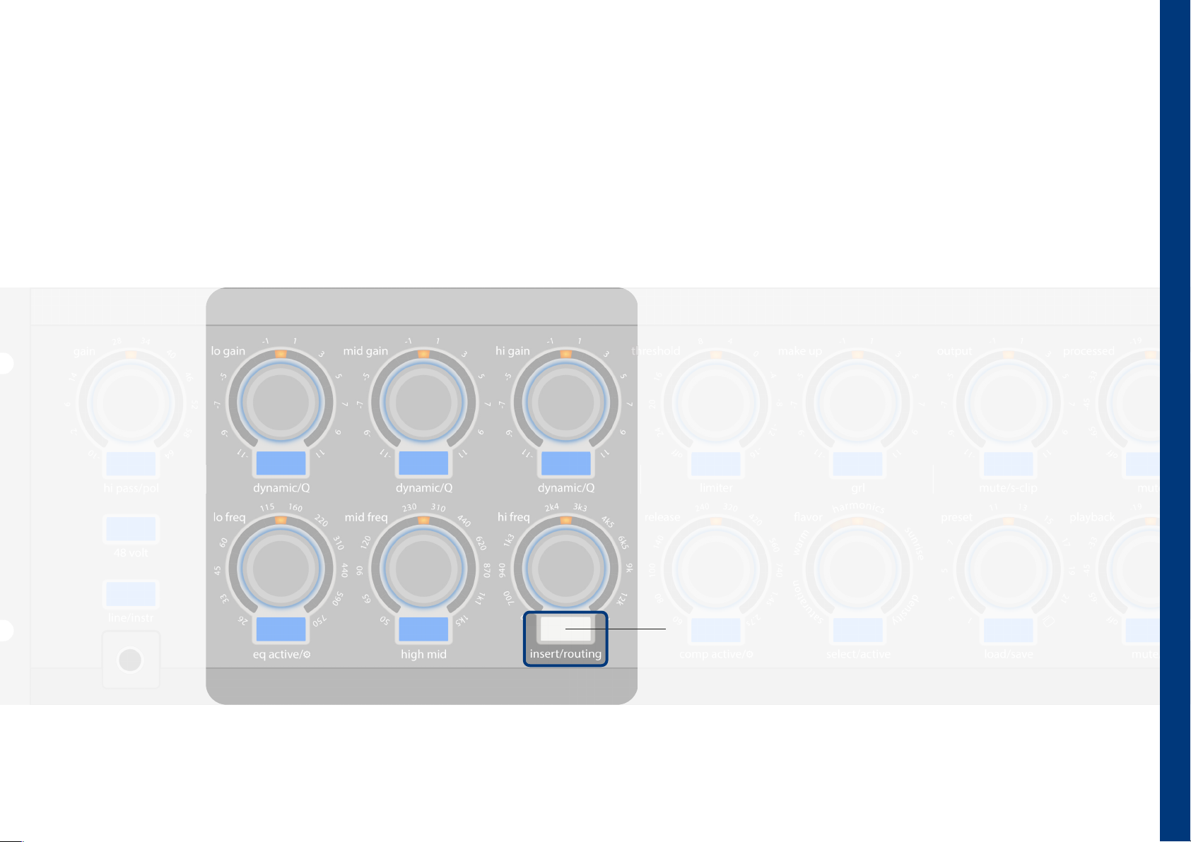
The channex|studio is equipped with a hardware insert, implemented as dedicated balanced XLR send and return connectors on the rear panel. By default, the insert point is
located between the equalizer and dynamics sections. Its tap point within the signal path can be congured in the routing menu (page 8), allowing external mono processors
to be integrated at the desired tap point in the processing chain. The insert send output can also be used as an additional line output. Its signal source can be positioned
anywhere within the signal path via the routing menu.
hardware insert active (or bypass)
A single press of the button activates the
physical insert path. Pressing it again
deactivates it. A long push of the button
enters the routing settings or returns from
them. (page 8)
hardware insert
7
Page 10
routing
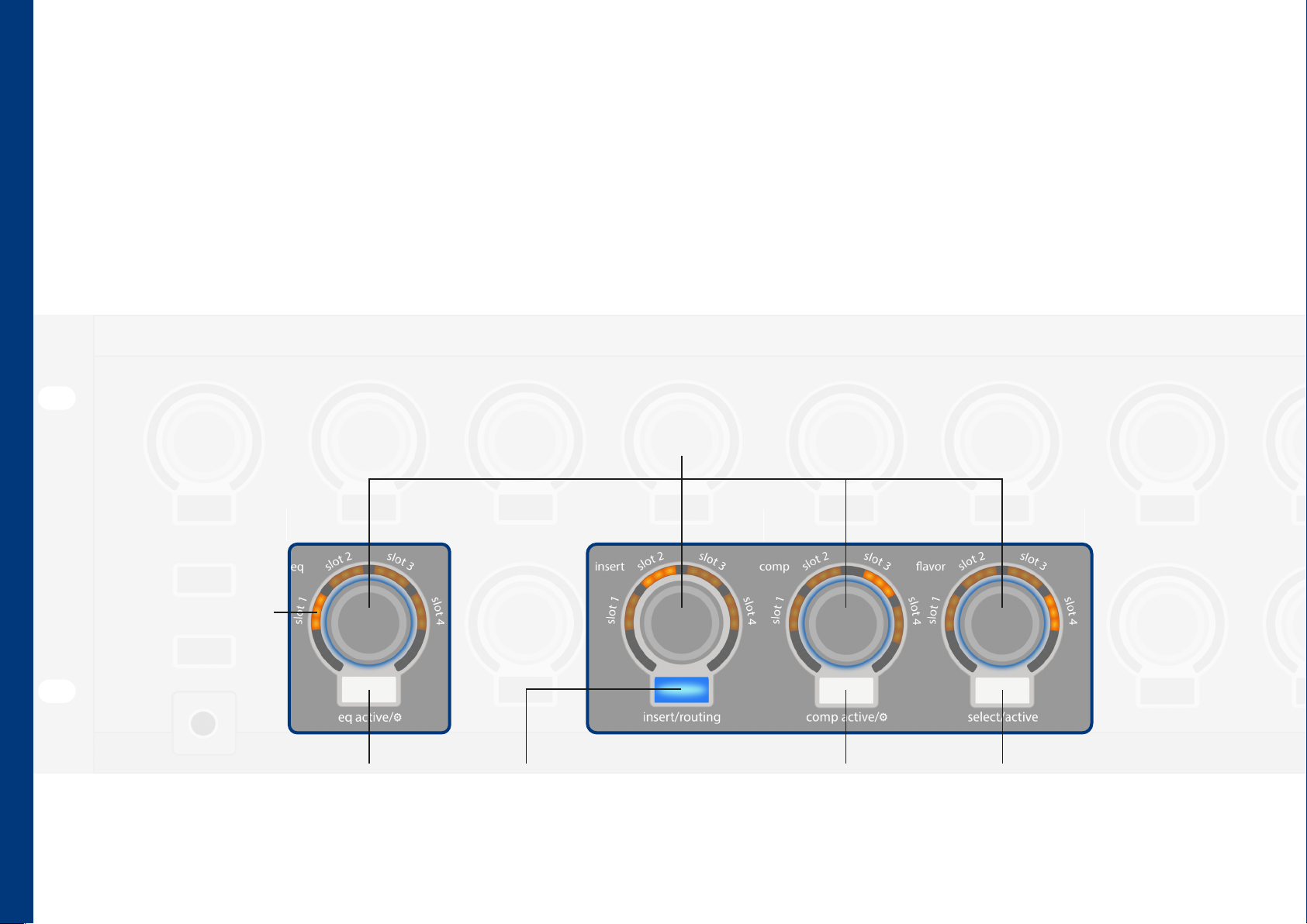
routing
The order of the processors within the channex|studio can be configured as needed. In the default setting, the signal flow is as follows: preamp → equalizer →
hardware insert → dynamics section → flavor → output. By long pushing the insert/routing (page 7), the device enters the routing menu for processor order. The
position can then be assigned using the respective controls for each section. The other processors adjust their positions accordingly. Preamp and output define the
start and end of the signal chain and therefore have fixed positions. This feature is a true novelty in analog signal processors of this complexity and provides the
engineer with near limitless possibilities. The plugin also provides an extended view, making it easy to see how the channex|studio effect processors are arranged.
eect processors position
This control selects the position of the
individual processors in the chain.
position indicator
The order of the respective
processors is indicated by the
bright LEDs. In this example
the equalizer is in the first
position.
equalizer
A short push switches
between inactive (blue LED)
and active (white LED).
8
hardware insert
A short push switches between inactive
(blue LED) and active (white LED). A long
push exits the menu.
dynamic section
A short push switches
between inactive (blue LED)
and active (white LED).
flavor
A long push switches between inactive
(blue LED) and active (white LED).
Page 11
dynamic section (compressor)
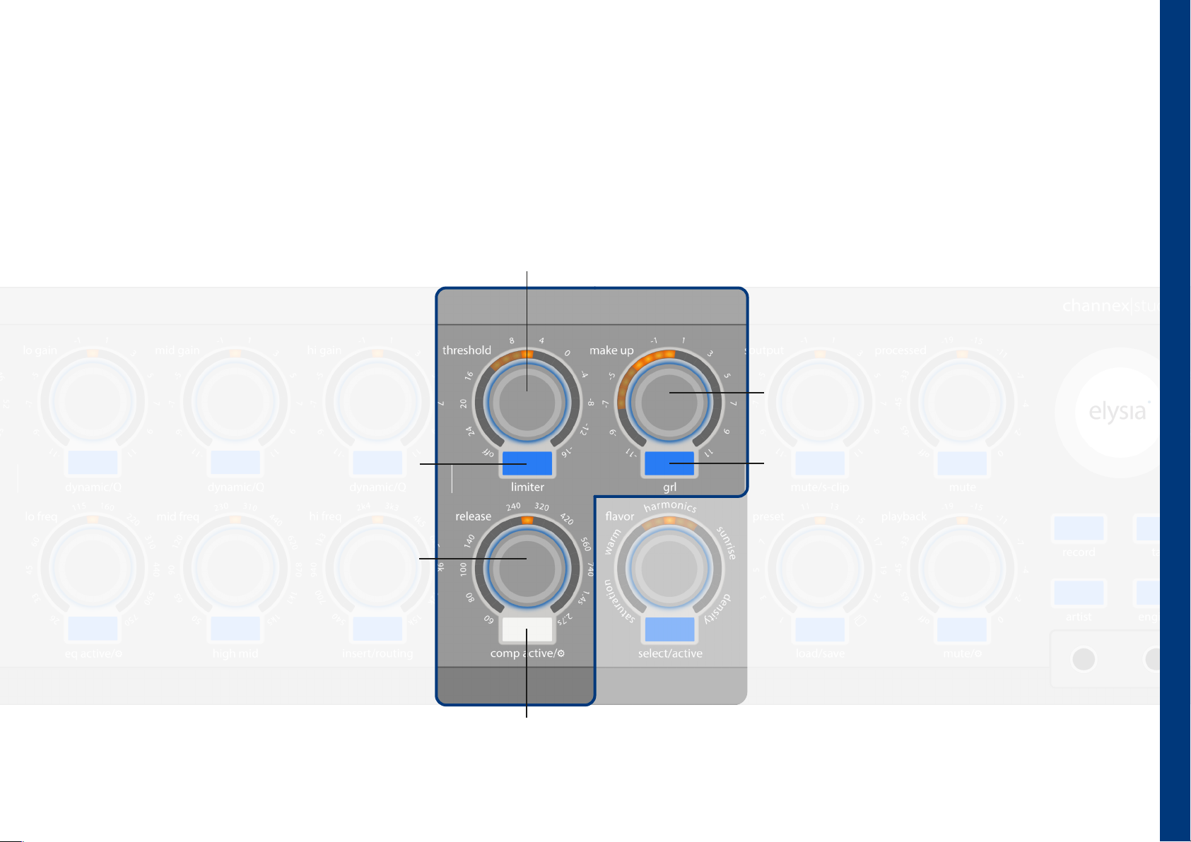
The dynamics section of the channex|studio is designed to deliver perfect results with maximum ease of use. Nevertheless, deeper control layers allow access to more
detailed parameters for both the compressor and the limiter. The compressor features a gain reduction limiter, offering a unique way to define and control the
maximum amount of compression applied to the signal. Compressor and limiter can be adjusted independently and used simultaneously. In addition, the compressor
provides further sound-shaping possibilities through its gain reduction limiter concept, combining a smooth soft-knee characteristic with an opto-inspired,
unobtrusive response that remains musically transparent even under more demanding settings.
threshold (compressor)
Sets the threshold for the dynamic processing of the compressor.
The resulting activity is displayed on the arch LED element.
make up gain
This control compensates for the level reduced by
dynamic processing. The arch LED element displays
the combined gain reduction of the limiter and
limiter
A short push switches to the view and
adjustment mode for the limiter (page 10)
and back again.
compressor.
gain reduction limiter (grl)
A short push switches to the display and adjustment
mode for the gain reduction limiter and back again.
release (compressor)
Sets the compressor release time, ranging
from 60 ms to 2.7 seconds.
dynamic section active (or bypass)
A short push switches between dynamic section inactive (blue LED) and
dynamic section active (white LED). A long push of the button enters the
setup of the dynamic section or returns from it. (page 11)
dynamik section (compressor)
9
Page 12
dynamic section (limiter)
dynamic section (limiter)
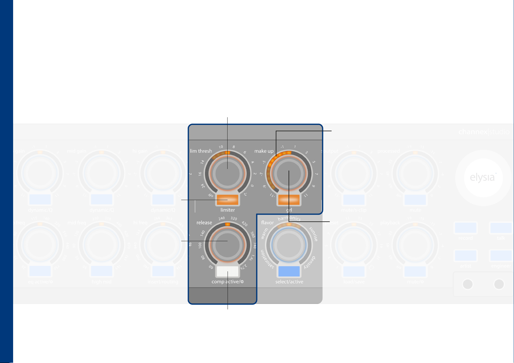
In its default configuration, the limiter operates with significantly more aggressive time constants and a higher compression ratio than the compressor. Its hard-knee
characteristic and the auto fast mode enable it to reliably capture even short transient peaks. The limiter’s detector runs in parallel to that of the compressor, with the
detector generating the highest level of gain reduction determining the overall attenuation behavior. This makes the limiter ideally suited for controlling even
percussive signals with short, high-level peaks.
threshold (limiter)
Sets the threshold for the dynamic processing of the limiter. The resulting
activity is displayed on the arch LED element.
gain reduction
The maximum level reduction allowed by the grl
is indicated by dimmed LEDs, while the resulting
actual level reduction is shown by bright LEDs.
compressor
A short push switches to the view and
adjustment mode for the limiter (page 9)
and back again.
release (limiter)
Sets the limiter release time, ranging from 60
ms to 2.7 seconds.
gain reduction limiter range
The maximum level reduction permitted by the
gain reduction limiter is indicated by dimmed LEDs.
10
dynamic section active (or bypass)
A short push switches between dynamic section inactive (blue LED) and
dynamic section active (white LED). A long push of the button enters the
setup of the dynamic section or returns from it. (page 11)
Page 13
dynamic section (setup ⚙)
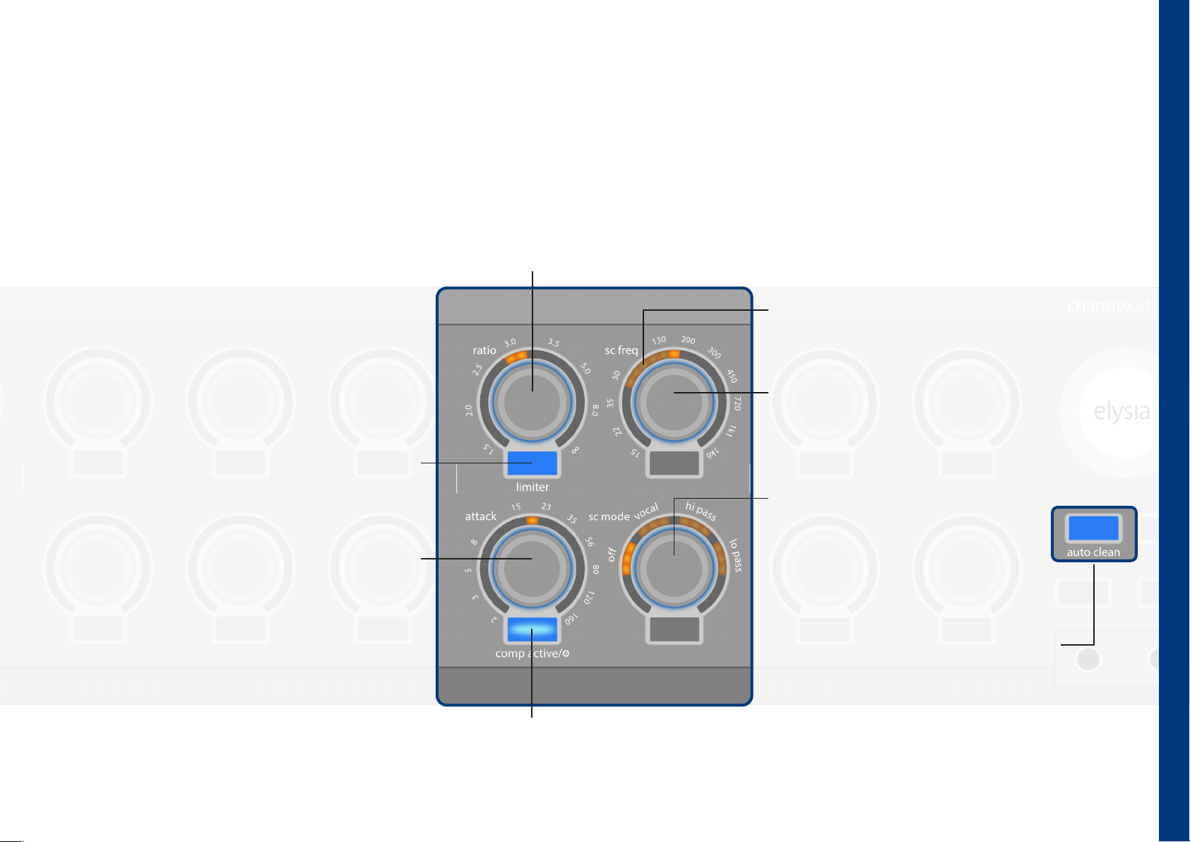
The setup menu of the dynamic section provides access to deeper conguration options, including the compression ratios of both dynamic processors, attack times and the
type and cuto frequency of the sidechain lter. In addition, this menu allows you to dene the behavior of controls and buttons after extended periods of inactivity. The
illuminated record button indicates the current status of this function.
ratio (select compressor or limiter)
Depending on the setting of the limiter button, this control adjusts the ratio for
the compressor (blue LED) or the limiter (orange LED).
gain reduction metering
The arch LED element displays the gain reduction. This makes
adjustments to ratio or attack directly visible.
selected filter frequency
limiter settings
A short push switches to the limiter settings
(orange LED). Pushing it again switches back to
the compressor settings (blue LED).
attack (compressor or limiter)
Depending on the setting of the limiter button, this
control adjusts the attack time for the compressor
(blue LED) or the limiter (orange LED).
Sets the cutoff frequency of the sidechain filter.
sidechain filter mode
Sets the type of sidechain filter. Options
include sidechain filter inactive (pos.1), a
vocal filter with reduced bass and
increased mid focus (position 2), a high-
pass filter (position 3), or a low-pass filter
(position 4) with a cutoff frequency
adjustable via sc freq.
dynamic section (setup)
dynamic section setup (long push)
A long push switches to the setup of the dynamic
section or back again.
auto clean
After 3 seconds of inactivity, the controls
automatically return to the default view. The
auto clean function for the dynamic section
can be activated (red LED) or deactivated (blue
LED) by pressing the record button in the
monitor section.
11
Page 14
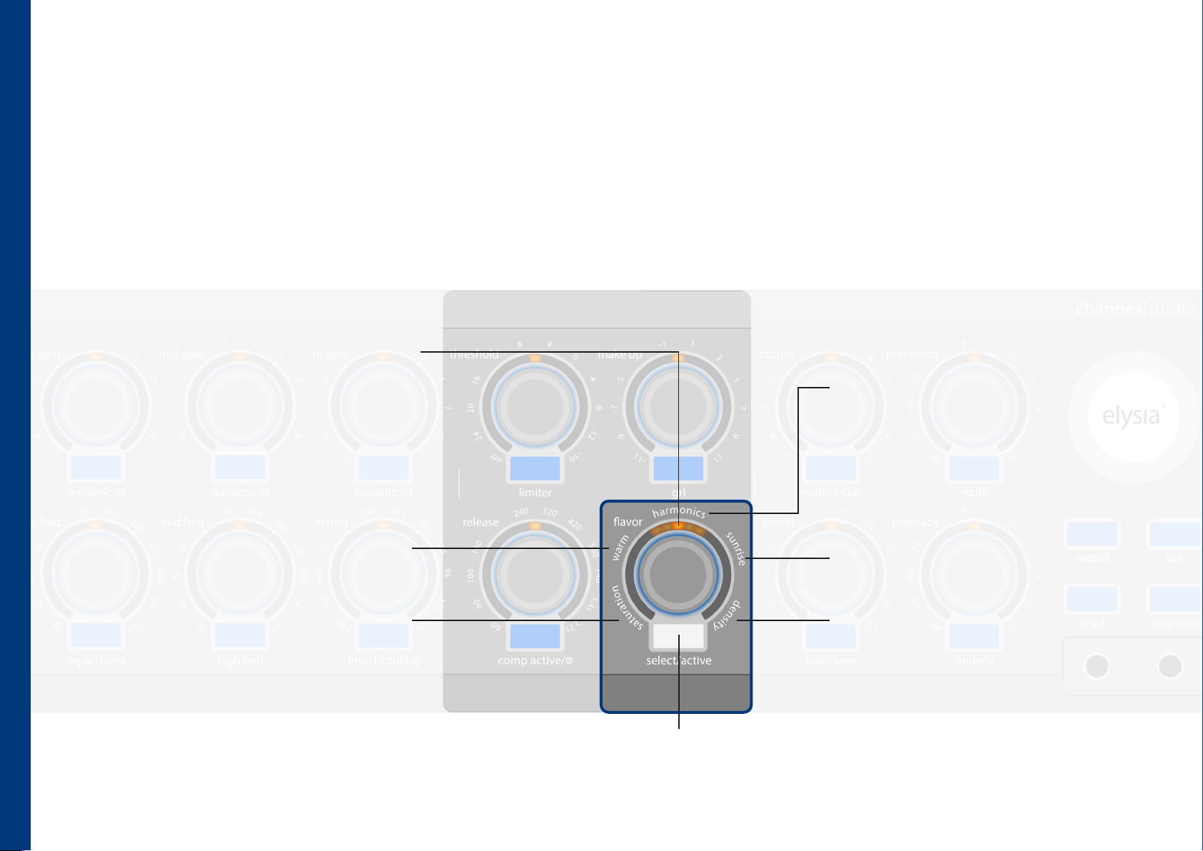
flavor
The flavor section provides four „spices” and compressor macros (density) that can be blended into the audio signal. Each flavor can be added independently and in
the desired amount. The channex|studio preamplifier is characterized by an exceptionally neutral and transparent sonic signature. The flavor section allows you to add
character and coloration to the signal already on its way into the DAW. This concept has already proven to be a secret weapon in the elysia skulpter 500. Of course,
already recorded signals can also benefit from this additional touch of sonic seasoning. The four flavor stages are arranged in series and can be used simultaneously.
This significantly expands the sonic palette of the channex|studio and, when used more creatively, can also serve as a tool for sound design.
indicator
The different flavors are divided into various
intensity levels. If only dimmed LEDs are
visible, the selected flavor is inactive. The
subsequent segments increase the respective
intensity.
flavor
warm
Activates a slew-rate limiter with a filtering
circuit. The signal becomes smoother and
more bass-focused, with slightly reduced
high frequencies. It resembles a proximity
effect.
saturation
A saturation circuit with a soft transfer
curve that mainly generates odd
harmonics and resembles an overdrive
effect.
harmonics
Activates a waveshaper and adds
predominantly even harmonics to the
signal. One half-wave of the signal is
amplified, which emphasizes transients at
higher settings.
sunrise
An inductor filter is blended into the signal,
resulting in a smooth and pleasant presence
boost.
density
Acts as a macro for multiple compressor
parameters. With a single turn, different
compression characteristics can be accessed.
12
flavor select/active (long push)
A short push cycles through the different flavors. A long push
activates (white LED) or deactivates (blue LED) the flavor section.
Page 15
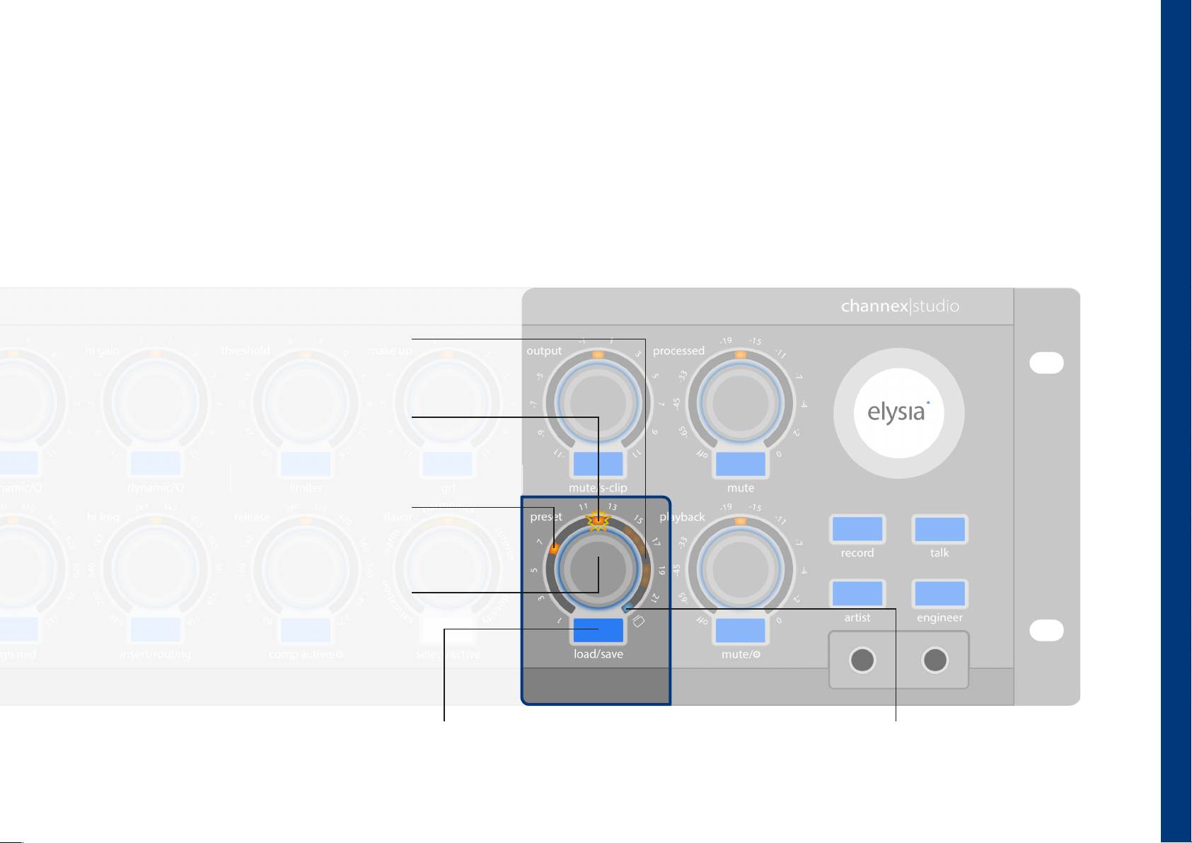
preset
The preset section allows you to store the current status and all settings of the entire unit in up to 22 memory locations, without the need for a computer connection
to the channex|studio. Presets stored on the device can be recalled at any time and further edited if required. This makes the channex|studio the perfect tool for
working environments with frequently changing yet recurring requirements, bridging the gap to the digital recording chain. The creative freedom of the engineer is no
longer limited by the concern of being unable to reproduce a once-discovered setting.
preset slots in use
The dimmed LEDs in the background indicate
occupied memory slots (if available).
preset preselector
Indicates the hardware memory slot from which
a preset is loaded or into which a preset will be
saved. This display remains active for 5 seconds
(blinking).
preset
loaded preset
The loaded preset is indicated by a permanently lit
orange LED. Computer presets are indicated by a
blue LED.
preset selection
Selects the hardware memory slot (1–22) from
which a preset is loaded or into which a preset is
saved.
load/save (long push)/delete (hold)
A single short push loads the selected preset without +48 V and monitor section. A second push within 4
seconds then loads the corresponding parameters. A long push saves the full hardware state to the selected
preset. To delete a preset, the button must be held. The float illumination indicates deletion by flashing red.
computer connection indicator
A dimmed blue LED indicates that the usb or ethernet
connection is linked. The blue LED turns bright when a plugin
preset is loaded or modied.
13
Page 16
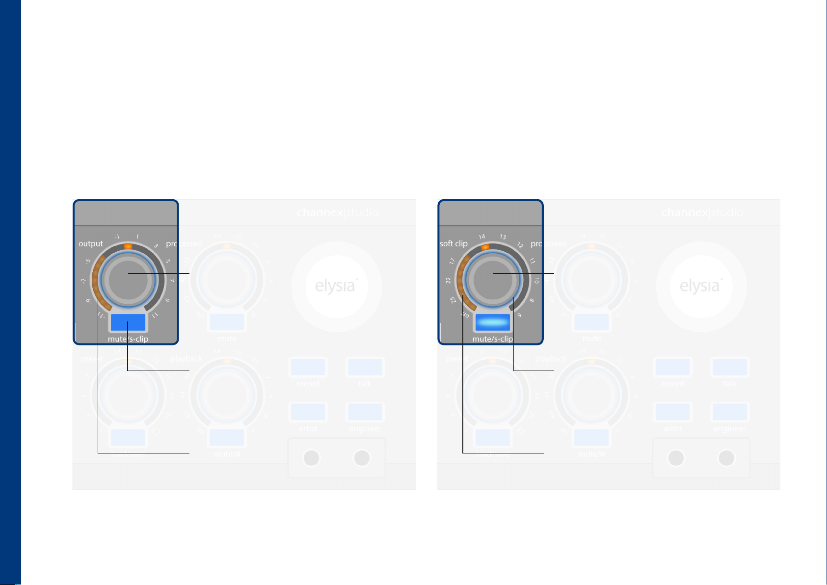
output
output
In the output section, the audio signal, including all processing applied in the effect sections, is made available for output to an A/D converter or other devices. The
signal present at this stage is routed to the rear-panel main out. An optionally engageable soft clipper helps effectively prevent clipping of following devices. The soft
clip limiter setting is best calibrated to the subsequent A/D converter by using a fast, sample-accurate PPM meter to determine the optimal threshold.
soft clipper
output level
Controls the signal level output at the rear main
out.
Limits the output signal level before the output
level stage to prevent clipping of following
devices. Note: Excessive limiting may result in
audible distortion. Use this function with caution
and moderate settings, especially for acoustic and
classical music.
14
mute/soft clipper (long push)
A short push mutes the signal at the main out
(red LED). A long push switches to the view and
adjustment mode for the soft clipper (orange
LED).
output metering
The arch LED element displays the signal level at
the output. An optional dBu level display can also
be enabled in the plugin.
activity indicator
The float illumination of the shell indicates the
activity of the soft clipper (orange LED). This
makes it always clear when the soft clipper is
active.
output metering
The arch LED element continues to display the
output signal level.
Page 17
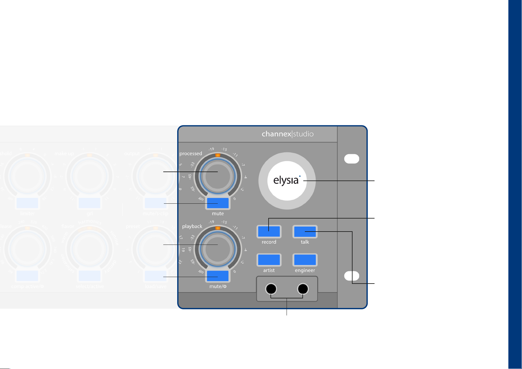
monitor section
In the monitor section, three independent monitor mixes can be created from the processed audio signal, optionally added effects and the signal present at the
playback input. These mixes are routed completely latency-free to the rear-panel headphone outputs, the monitor output, as well as the front-panel headphone
connections. This ensures that the focus remains entirely on the artistic performance, without the recording being affected by any digital delay in the monitoring path.
Using the record function, two individual mute macros can be assigned to the monitor sources. The talk button activates the optionally connected talkback
microphone. The illuminated elysia logo serves as the power switch for the channex|studio, provided that the rear-panel power switch is set to the ON position. In all
cases, a warm-up period of 15 to 20 minutes is recommended prior to recording, allowing all internal components to reach a stable and fully reproducible operating
condition.
processed signal
Sets the level of the processed input signal
in the monitor controller mix.
mute processed signal
Mutes the processed input signal in the
monitor controller mix (red LED).
playback input signal
Sets the level of the signal present at the
playback input in the monitor controller
mix.
power button (long push)
A long push turns the channex|studio on or off.
When the device powers up a short audible
click feedback signal is played .
record mute macro
When the record button is activated, you can
choose between two mute states. This state
can be set individually for the artist (red LED),
engineer (orange LED) and the monitor
controller mix.
monitor section
mute playback signal
A short push mutes the playback signal in
the monitor controller mix (red LED).
talkback button
Activates an optionally connectable talkback
microphone. The footswitch input on the
rear of the device mirrors this function. When
activated, the button lights up white.
headphone outputs
The connections for the artist and engineer headphones. These
connections are also available on the rear of the device.
15
Page 18
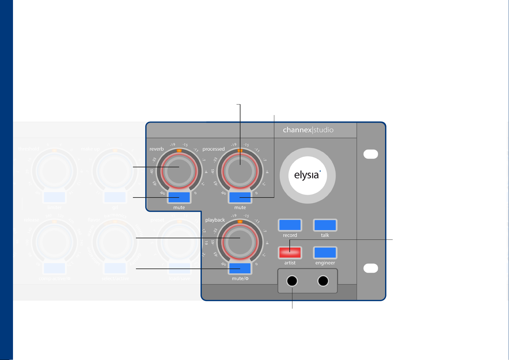
monitor section (artist)
Independent monitor mixes can be created for both the artist and engineer headphone paths. These mixes can also differ from the general monitor mix present at
the monitor out. The settings for the individual mixes are visualized through different colors in the backlighting of the rotary controls. The talk and record functions
remain available across all monitoring layers.
reverb level
Sets the level of the internal reverb or
the signal present at the FX input in
the artist monitor mix.
mute FX
Mutes the internal reverb in the artist
monitor mix (red LED).
monitor section (artist )
playback input signal
Sets the level of the signal present at
the playback input in the artist
monitor mix.
processed signal
Sets the level of the processed input signal in
the artist monitor mix.
mute processed signal
Mutes the processed input signal in the
artist monitor mix (red LED).
artist mix button
A short push of the artist button
switches to the settings for the
monitor mix routed to the artist
headphone outputs (red LED +
float illumination). A second
short push switches back to the
monitor controller mix settings.
16
mute playback signal
A short push mutes the playback signal in
the artist monitor mix (red LED).
artist headphone output
The connection for the artist headphones. This
connection is also available on the rear of the device.
Page 19
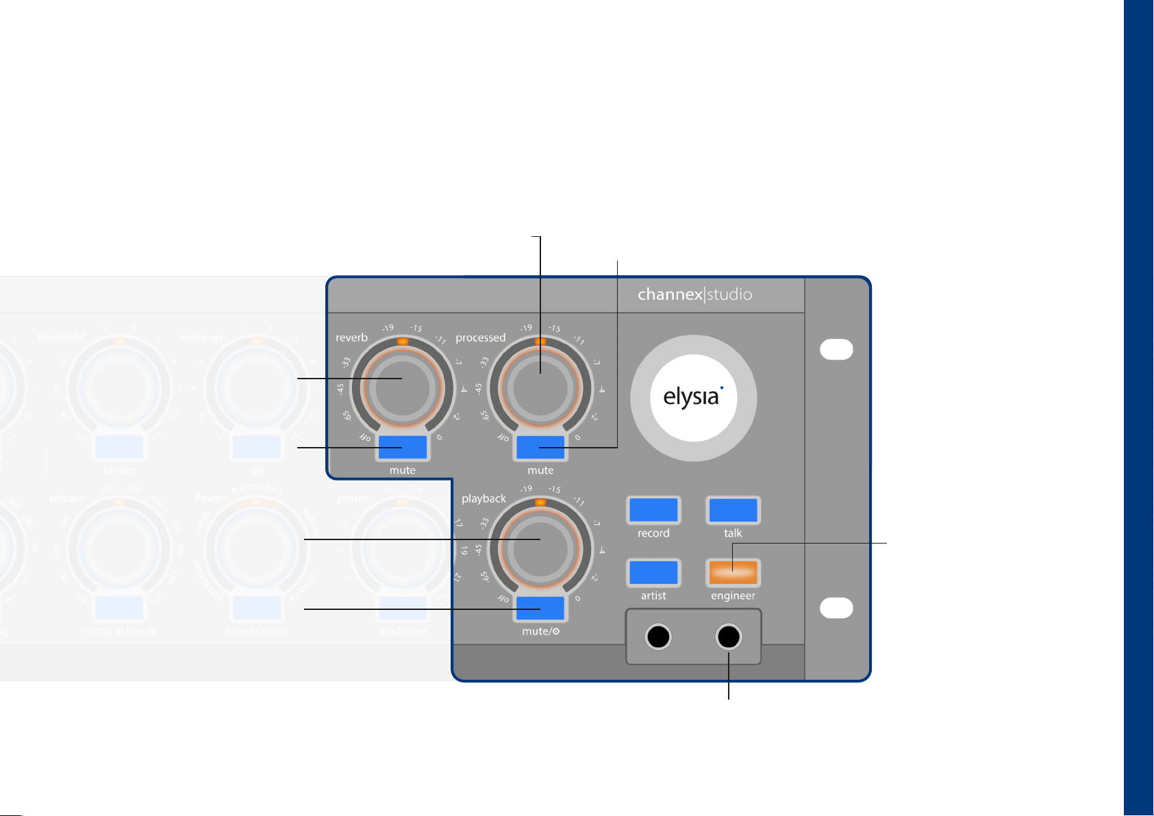
monitor section (engineer)
Independent monitor mixes can be created for both the artist and engineer headphone paths. These mixes can also differ from the general monitor mix present at
the monitor out. The settings for the individual mixes are visualized through different colors in the backlighting of the rotary controls. The talk and record functions
remain available across all monitoring layers.
processed signal
Sets the level of the processed input signal in the
engineer monitor mix.
reverb level
Sets the level of the internal reverb
or the signal present at the FX input
in the engineer monitor mix.
mute FX
Mutes the internal reverb in the
engineer monitor mix (red LED).
playback input signal
Sets the level of the signal present at
the playback input in the engineer
monitor mix.
mute processed signal
Mutes the processed input signal in the
engineer monitor mix (red LED).
engineer mix button
A short push of the engineer
button switches to the settings for
the monitor mix routed to the
engineer headphone outputs
(orange LED + float illumination). A
second short push switches back to
the monitor controller mix settings.
monitor section (engineer)
mute playback signal
A short push mutes the playback signal in
the engineer monitor mix (red LED).
engineer headphone output
The connection for the engineer headphones. This
connection is also available on the rear of the device.
17
Page 20
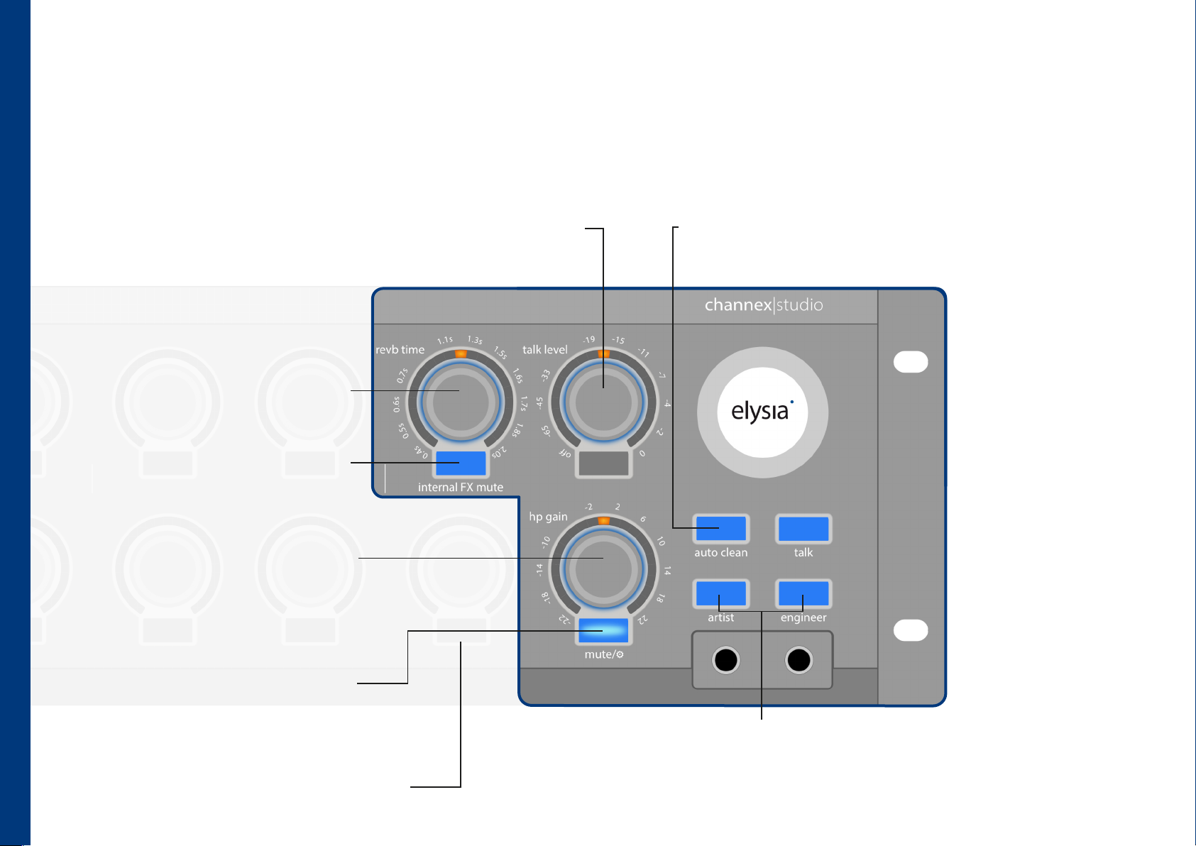
monitor section (setup ⚙)
This submenu provides access to advanced settings such as the reverb time of the internal effects processor, talkback level, maximum output level for the headphone
outputs, as well as gain and phantom power for a connected talkback microphone. In addition, this menu allows you to define the behavior of controls and buttons
after extended periods of inactivity (auto clean). The illuminated record button indicates the current status of this function.
reverb time
Controls the decay time of the integrated
reverb processor.
internal FX mute
The internal FX mute button mutes the
internal reverb processor, so that only effects
routed via the FX input are audible.
monitor section (setup)
headphone gain
Depending on the selection of artist or
engineer, this control sets the volume for the
selected headphone outputs. The shell elements
change color to indicate artist (red LED) or
engineer (orange LED).
talkback level
Depending on the selection of monitor controller
mix (blue LED), artist (red LED) or engineer (orange
LED), this control sets the talkback level for the
selected monitor paths.
auto clean
After 3 seconds of inactivity, the controls automatically return to the
default view. The auto clean function for the monitor section can be
activated (red LED) or deactivated (blue LED) by pressing the record
button.
talkback
microphone settings
The settings for the
talkback microphone
(+48 V and gain) can be
found in the preamp
section on the left side of
the channex|studio.
18
monitor setup (long push)
A long push switches to the monitor section
setup or back again.
Note: By pressing and holding the load/save button on the
preset shell, a parameter reset for the entire channex|studio
can be performed.
artist & engineer settings
Depending on the selection of artist (red LED) or engineer
(orange LED), the respective settings can be congured here.
Page 21
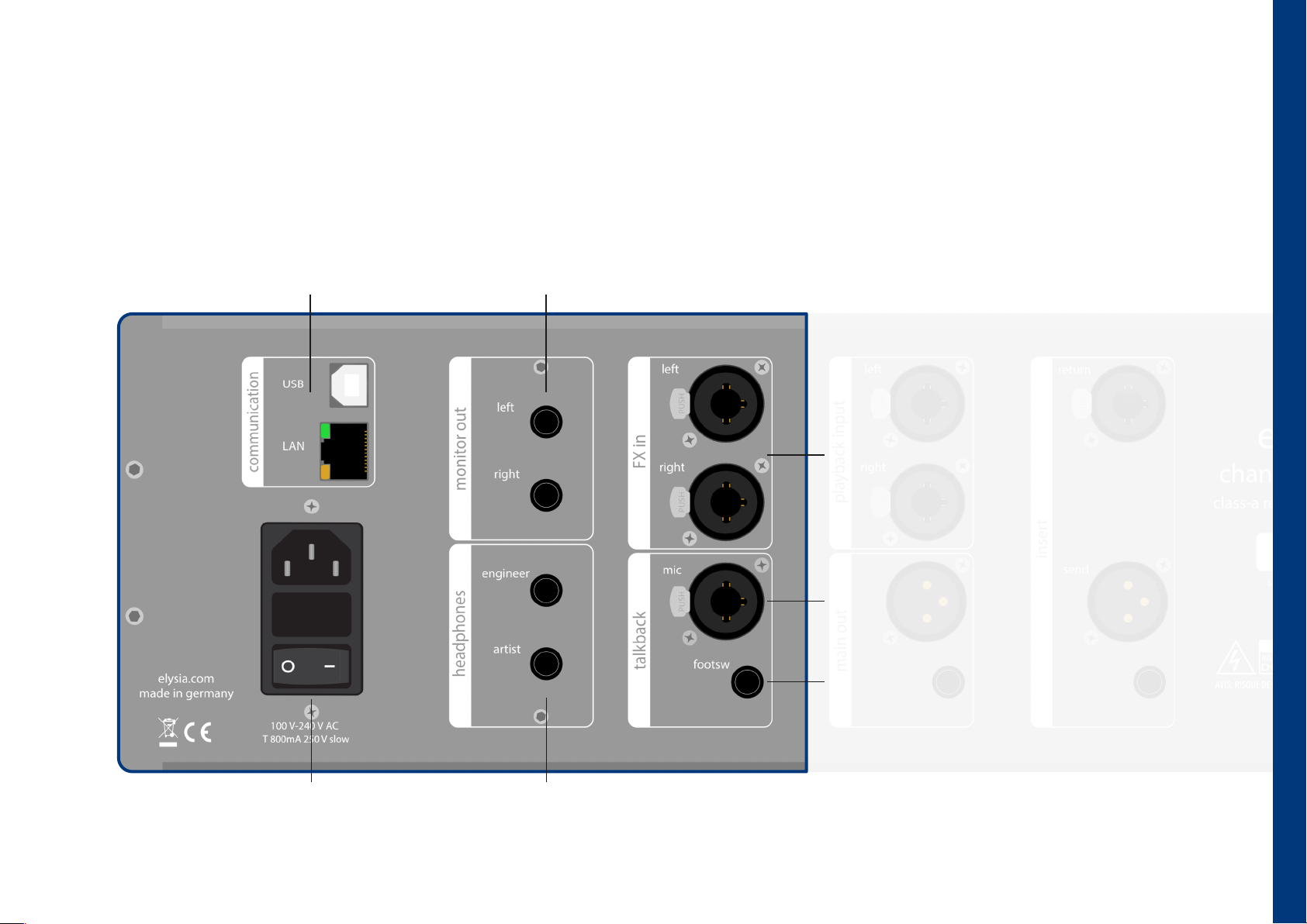
connections (left)
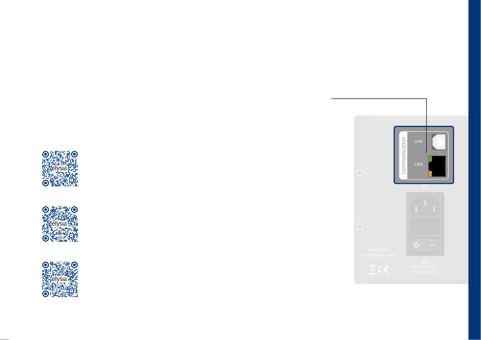
computer communication
The USB and LAN ports for connecting to the
control plugin. Use your PC to update your
firmware via USB. (software manual)
monitor output
Connection for external monitor controllers. (page 15)
external FX input
An external stereo effect can be connected here,
which can be mixed into the signal via the monitor
paths. This input is mixed with the existing internal
reverb. The internal reverb can be deactivated using
the internal FX mute button. (page 19)
talkback microphone input
The connection for an external talkback microphone.
If the microphone requires +48V phantom power, it
can be activated in the monitor setup menu using
the 48 volt button.
connections (left)
main power module
This module combines the line cord connector,
the on/o switch and the fuse (800mA) holder.
talkback microphone footswitch
The connection for a footswitch to activate or
deactivate the talkback function. The polarity is
automatically detected when plugged in. (page 15)
engineer & artist headphone output
The headphone outputs for artist and engineer. These outputs mirror
the corresponding connectors on the control panel. (page 15)
19
Page 22
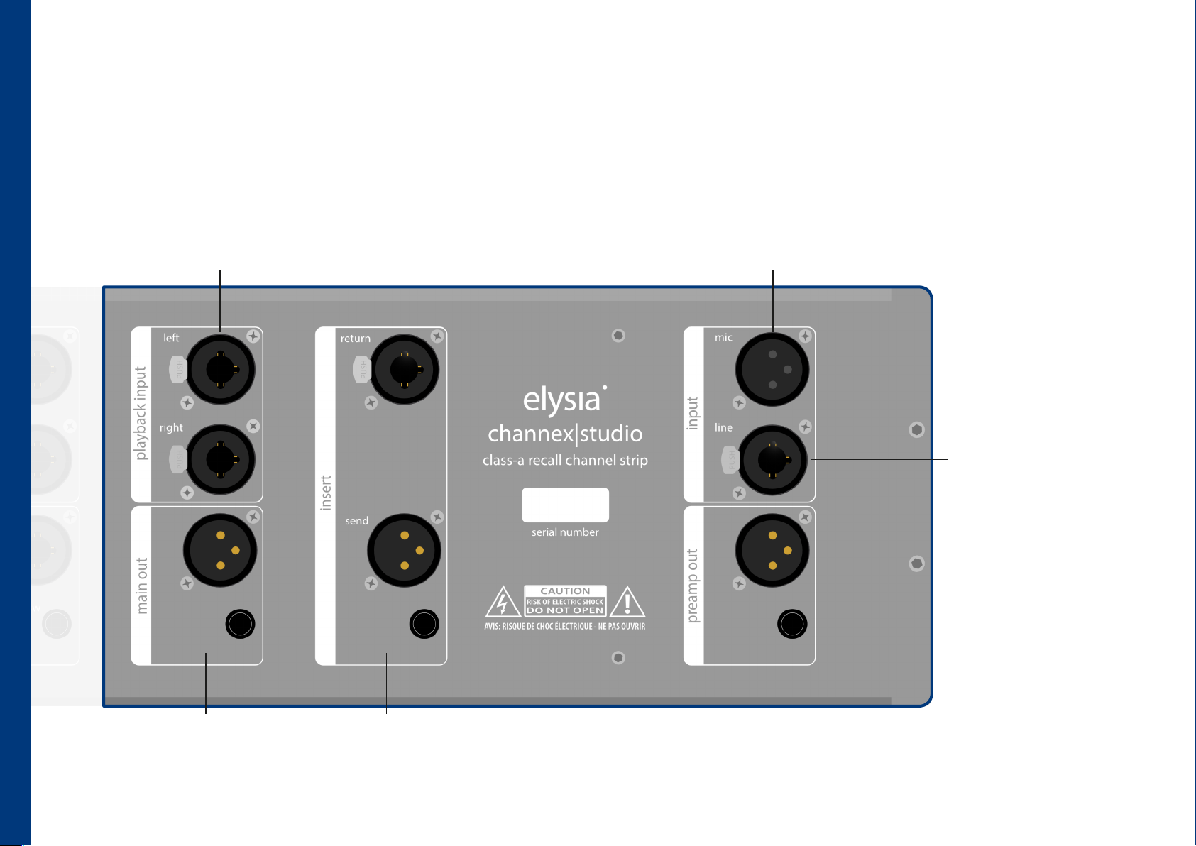
connections (right)
playback input
An external stereo source, such as the playback for a recording, can
be connected and mixed into the monitor mixes. (page 15)
microphone input
The connector for the microphone input signal. (mic and line can
be connected simultaneously. The input source selection is made
via the line/instr button on the front panel. (page 2)
line input
The connector for the line
input signal. Line and
connections (right)
Instrument (front) can be
connected simultaneously,
with the source selection
made via the line/instr
button on the front panel.
20
main output
The output signal processed by
channex|studio. (page 14)
hardware insert send & return
Symmetrical connections for external mono
processors to be inserted into the signal path
of the channex|studio. (page 7)
preamp (direct) output
Here, the signal can be tapped in parallel directly
after the preamp and high-pass filter.
Page 23
software
With the free control plugin, the channex|studio can be fully remote controlled. It allows access to presets stored on the hardware as well as the creation of additional
presets and folder structures. The DAW version of the plugin is available in common formats and extends the functionality of the standalone version by enabling
automation of many parameters and saving the state of both plugin and hardware within a DAW session.
connecting your computer to channex|studio
To connect the channex|studio hardware with the plugin, the hardware must be powered on and either the standalone
plugin, or the DAW plugin must be running. Clicking on the not connected status indicator at the top right of the plugin
window opens the connection manager. Select the USB or Ethernet connection type to then determine whether the
current settings in the plugin should be transferred to the hardware, or vice versa.
Clicking connect will then establish the connection to the channex|studio hardware. If no connection can be established,
additional settings may be required. (software manual)
software download
Here you will always find the latest software for Windows and macOS available for download. The
package includes the DAW plugin in AU, AAX and VST3 formats, as well as the standalone version that
works outside the DAW. In addition, the folder always contains the latest firmware version for your
elysia .com/downlo ads
channex|studio.
software
elysia .com/downlo ads
elysia .com/downlo ads
software manual download
This manual provides information on the channex|studio plugin. It includes details about the controls,
the settings and how to connect the computer to the hardware.
hardware manual download
Here you will find the hardware manual of the channex|studio. The manual includes technical data and
is always available as a digital PDF whenever you need it.
21
Page 24

precautions
precautions
warning: high voltage
- risk of electric shock.
- do not open chassis.
- refer service to qualied service sta only.
- replace fuse (800mA) with the same type and value only.
- this device must be connected to ground.
- Do not use a damaged power cord.
- never place containers with liquid, e.g. beverages or a vase, on the unit.
- do not expose this device to rain or moisture.
- do not use this device near water, e.g. swimming pool, bathtub or wet basement.
caution: temperature
- surfaces of the device may become hot during operation.
- do not install this device near any heat source such as radiators, stoves or other heat sources.
- always allow enough ventilation space around the unit for air circulation.
- do not cover circulation vents.
22
caution: humidity
- if this device is moved from a cold place to a warm room, condensation can occur inside the device. To avoid damaging the unit
please allow it to reach room temperature before switching on.
caution: connecting & mounting
- never connect the output of a power amplier to this device.
- place the unit on a rigid board or x it to an appropriate rack.
- use the device according to this manual only.
Page 25
legal information
warranty
The channex|studio is covered by a limited warranty for a period of 2 years against defects in parts and labor from the date of purchase. Natural wear is not covered by this
warranty. Repairs or replacements will not extend the warranty period. The warranty is given to the original purchaser only and is not transferable. elysia will only give warranty
on products purchased through authorized elysia dealers. The warranty will only be valid in the country of the original purchase unless otherwise pre-authorized by elysia.
All warranties become void when the product has been damaged by misuse, accident, neglect, modication, tampering or unauthorized alteration by anyone other than elysia
authorized service personnel. The warrantor assumes no liability for property damage or any other incidental or consequential damage whatsoever which may result from
failure of this product. Any and all warrantees of merchantability and tness implied by law are limited to the duration of the expressed war ranty.
elysia will not pay for express or overnight freight service or pay for shipments to locations outside Germany. All damages caused by transport are not covered by this warranty.
This warranty gives you specic legal rights and you may also have other rights which vary from state to state. Some of the above limitations may not apply to you.
compliance
elysia GmbH, Am Panneschopp 18, 41334 Nettetal, Germany, declares with sole responsibility that this product complies with the following norms and directives:
- 2006/95/EG Low Voltage Directive (formerly 73/23/EWG or 93/68/EWG)
- 89/336/EWG EMC (Electromagnetic Compatibility) Directive
- DIN EN 55103-1 EMC of audio equipment - Emission
- DIN EN 55103-2 EMC of audio equipment - Immunity
This declaration becomes invalid by any unapproved modication of the device.
Nettetal, 01.07.2026 - Ruben Tilgner
legal information
conformity
The conformity of this device to the EU directives is conrmed by the CE mark on the device.
This declaration becomes invalid by any unapproved modication of the device.
Nettetal, 01.07.2026 - Ruben Tilgner
23
Page 26
channex|studio is proudly designed and manufactured in Nettetal, Germany.
elysia GmbH
Am Panneschopp 18
41334 Nettetal
Version 1.0 © 2026 elysia GmbH
 Loading...