

Page 1
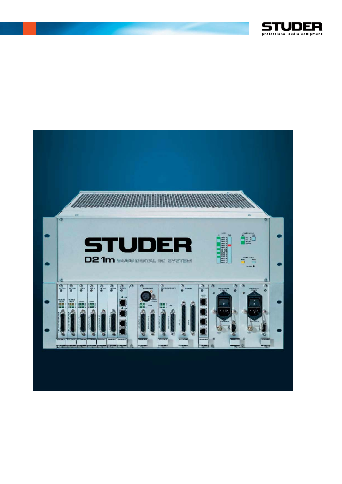
Studer D21m
I/O System Components
Product Information
(January 2009, 12th Edition)
Page 2

Prepared and edited by Copyright by Studer Professional Audio GmbH
Studer Professional Audio GmbH Printed in Switzerland
Technical Documentation Order no. BD10.275102-12 (0109)
Althardstrasse 30
CH-8105 Regensdorf – Switzerland
http://www.studer.ch Subject to change
Studer is a registered trade mark of Studer Professional Audio GmbH, Regensdorf
Page 3
A Safety Information
To reduce the risk of electric shock, do not remove covers. No userserviceable parts inside. Refer servicing to qualified service personnel
(i.e., persons having appropriate technical training and experience necessary to be aware of hazards to which they are exposed in performing a
repair action, and of measures to minimize the danger of themselves).
This symbol alerts the user to the presence of un-insulated dangerous
voltage within the equipment that may be of sufficient magnitude to constitute a risk of electric shock to a person.
This symbol alerts the user to important instructions for operating and
maintenance in this documentation.
Safety Information
CLASS I
LED PRODUCT
CLASS I
LASER PRODUCT
A1 First Aid
Assemblies or sub-assemblies of this product can contain opto-electronic
devices. As long as these devices comply with Class I of laser or LED
products according to EN 60825-1:1994, they will not be expressly
marked on the product. If a special design should be covered by a higher
class of this standard, the device concerned will be marked directly on
the assembly or sub-assembly in accordance with the above standard.
In Case of Electric Shock: Separate the person as quickly as possible from the electric power
source:
• By switching off the equipment,
• By unplugging or disconnecting the mains cable, or
• By pushing the person away from the power source, using dry,
insulating material (such as wood or plastic).
• After having suffered an electric shock, always consult a doctor.
Warning! Do not touch the person or his clothing before the power is turned
off, otherwise you stand the risk of suffering an electric shock as
well!
If the Person is Unconscious: • Lay the person down
• Turn him to one side
• Check the pulse
• Reanimate the person if respiration is poor
• Call for a doctor immediately.
I
Page 4

Installation/Maintenance/ESD
B General Installation Instructions
Please consider besides these general instructions also any product-specific
B1 Unpacking
Check the equipment for any transport damage. If the unit is mechanically
B2 Installation Site
Install the unit in a place where the following conditions are met:
• The temperature and the relative humidity of the environment must be
• Condensation must be avoided. If the unit is installed in a location with
• Unobstructed air flow is essential for proper operation. Air vents of the
• The unit must not be heated up by external sources of heat radiation
B3 Earthing and Power Supply
instructions in the “Installation” chapter of this manual.
damaged, if liquids have been spilled or if objects have fallen into the unit,
it must not be connected to the AC power outlet, or it must be immediately
disconnected by unplugging the power cable. Repair must only be per-
formed by trained personnel in accordance with the applicable regulations.
within the specified limits during operation of the unit. Relevant values
are the ones at the air inlets of the unit.
large variation of ambient temperature (e.g. in an OB-van), appropriate
precautions must be taken before and after operation (for details on this
subject, refer to Appendix 1).
unit are a functional part of the design and must not be blocked in any
way during operation (e.g. by objects placed upon them, placement of
the unit on a soft surface, or installation of the unit within a rack or
piece of furniture).
(sunlight, spot lights).
Earthing of units with mains supply (class I equipment) is performed via
the protective earth (PE) conductor integrated in the mains cable. Units
with battery operation (< 60 V, class III equipment) must be earthed separately.
Earthing the unit is one of the measures for protection against electrical
shock hazard (dangerous body currents). Hazardous voltage may not only
be caused by a defective power supply insulation, but may also be introduced by the connected audio or control cables.
If the unit is installed with one or several external connections, its earthing
must be provided during operation as well as while the unit is not operated.
If the earthing connection can be interrupted, for example, by unplugging
the mains plug of an external power supply unit, an additional, permanent
earthing connection must be installed using the provided earth terminal.
Avoid ground loops (hum loops) by keeping the loop surface as small as
possible (by consequently guiding the earth conductors in a narrow, parallel way), and reduce the noise current flowing through the loop by inserting
an additional impedance (common-mode choke).
II
Page 5
ESD/Repair
Class I Equipment (Mains Operation)
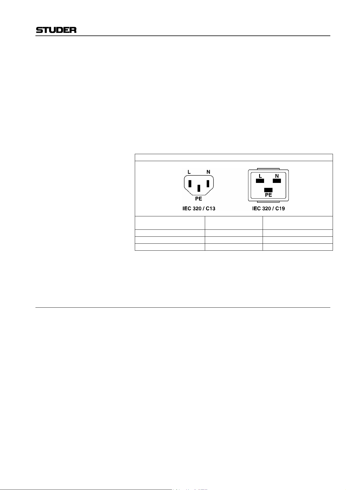
Should the equipment be delivered without a matching mains cable, the
latter has to be prepared by a trained person using the attached female plug
(IEC320/C13 or IEC320/C19) with respect to the applicable regulations in
your country.
Before connecting the equipment to the AC power outlet, check that the
local line voltage matches the equipment rating (voltage, frequency) within
the admissible tolerance. The equipment fuses must be rated in accordance
with the specifications on the equipment.
Equipment supplied with a 3-pole appliance inlet (protection conforming to
class I equipment) must be connected to a 3-pole AC power outlet so that
the equipment cabinet is connected to the protective earth.
For information on mains cable strain relief please refer to Appendix 2.
Female Plugs (IEC320), Front-Side View:
European Standard
(CENELEC)
Brown L (Live) Black
Blue N (Neutral) White
Green/Yellow PE (Protective Earth) Green (or Green/Yellow)
North American Standard
(NAS)
Class III Equipment (Battery Operation up to 60 V
DC
)
Equipment of this protection class must be earthed using the provided earth
terminal, if one or more external signals are connected to the unit (see explanation at the beginning of this paragraph).
B4 Electromagnetic Compatibility (EMC)
The unit conforms to the protection requirements relevant to electromag-
netic phenomena that are listed in guidelines 89/336/EC and FCC, part 15.
• The electromagnetic interference generated by the unit is limited in such
a way that other equipment and systems can be operated normally.
• The unit is adequately protected against electromagnetic interference so
that it can operate properly.
The unit has been tested and conforms to the EMC standards of the speci-
fied electromagnetic environment, as listed in the following declaration.
The limits of these standards ensure protection of the environment and corresponding noise immunity of the equipment with appropriate probability.
However, a professional installation and integration within the system are
imperative prerequisites for operation without EMC problems.
For this purpose, the following measures must be followed:
• Install the equipment in accordance with the operating instructions. Use
the supplied accessories.
• In the system and in the vicinity where the equipment is installed, use
only components (systems, equipment) that also fulfill the EMC standards for the given environment.
• Use a system grounding concept that satisfies the safety requirements
(class I equipment must be connected with a protective ground conduc-
III
Page 6
Installation/Maintenance/ESD
tor) and that also takes into consideration the EMC requirements. When
deciding between radial, surface, or combined grounding, the advantages and disadvantages should be carefully evaluated in each case.
• Use shielded cables where shielding is specified. The connection of the
shield to the corresponding connector terminal or housing should have a
large surface and be corrosion-proof. Please note that a cable shield
connected only single-ended can act as a transmitting or receiving antenna within the corresponding frequency range.
• Avoid ground loops or reduce their adverse effects by keeping the loop
surface as small as possible, and reduce the noise current flowing
through the loop by inserting an additional impedance (e.g. commonmode choke).
• Reduce electrostatic discharge (ESD) of persons by installing an appropriate floor covering (e.g. a carpet with permanent electrostatic filaments) and by keeping the relative humidity above 30%. Further measures (e.g. conducting floor) are usually unnecessary and only effective if
used together with corresponding personal equipment.
• When using equipment with touch-sensitive operator controls, please
take care that the surrounding building structure allows for sufficient
capacitive coupling of the operator. This coupling can be improved by
an additional, conducting surface in the operator’s area, connected to the
equipment housing (e.g. metal foil underneath the floor covering, carpet
with conductive backing).
C Maintenance
All air vents and openings for operating elements (faders, rotary knobs)
must be checked on a regular basis, and cleaned in case of dust accumulation. For cleaning, a soft paint-brush or a vacuum cleaner is recommended.
Cleaning the surfaces of the unit is performed with a soft, dry cloth or a
soft brush.
Persistent contamination can be treated with a cloth that is slightly humidi-
fied with a mild cleaning solution (soap-suds).
For cleaning display windows, commercially available computer/TV
screen cleaners are suited. Use only a slightly damp (never wet) cloth.
Never use any solvents for cleaning the exterior of the unit! Liquids must
never be sprayed or poured on directly!
For equipment-specific maintenance information please refer to the corre-
sponding chapter in the Operating and Service Instructions manuals.
D Electrostatic Discharge during Maintenance and Repair
Caution: Observe the precautions for handling devices sensitive to electrostatic dis-
charge!
Many semiconductor components are sensitive to electrostatic discharge
(ESD). The life-span of assemblies containing such components can be
drastically reduced by improper handling during maintenance and repair
work. Please observe the following rules when handling ESD sensitive
components:
• ESD sensitive components should only be stored and transported in the
packing material specifically provided for this purpose.
• When performing a repair by replacing complete assemblies, the removed assembly must be sent back to the supplier in the same packing
IV
Page 7

ESD/Repair
material in which the replacement assembly was shipped. If this should
not be the case, any claim for a possible refund will be null and void.
• Unpacked ESD sensitive components should only be handled in ESD
protected areas (EPA, e.g. area for field service, repair or service bench)
and only be touched by persons who wear a wristlet that is connected to
the ground potential of the repair or service bench by a series resistor.
The equipment to be repaired or serviced as well as all tools and electrically semi-conducting work, storage, and floor mats should also be connected to this ground potential.
• The terminals of ESD sensitive components must not come in uncontrolled contact with electrostatically chargeable (voltage puncture) or
metallic surfaces (discharge shock hazard).
• To prevent undefined transient stress of the components and possible
damage due to inadmissible voltages or compensation currents, electrical connections should only be established or separated when the
equipment is switched off and after any capacitor charges have decayed.
E Repair
Removal of housing parts, shields, etc. exposes energized parts. For this
reason the following precautions must be observed:
• Maintenance may only be performed by trained personnel in accordance
with the applicable regulations.
• The equipment must be switched off and disconnected from the AC
power outlet before any housing parts are removed.
• Even if the equipment is disconnected from the power outlet, parts with
hazardous charges (e.g. capacitors, picture tubes) must not be touched
until they have been properly discharged. Do not touch hot components
(power semiconductors, heat sinks, etc.) before they have cooled off.
• If maintenance is performed on a unit that is opened and switched on, no
un-insulated circuit components and metallic semiconductor housings
must be touched, neither with your bare hands nor with un-insulated
tools.
Certain components pose additional hazards:
• Explosion hazard from lithium batteries, electrolytic capacitors and
power semiconductors (watch the component’s polarity. Do not short
battery terminals. Replace batteries only by the same type).
• Implosion hazard from evacuated display units.
• Radiation hazard from laser units (non-ionizing), picture tubes (ioniz-
ing).
• Caustic effect of display units (LCD) and components containing liquid
electrolyte.
Such components should only be handled by trained personnel who are
properly protected (e.g. safety goggles, gloves).
V
Page 8
Repair/Disposal
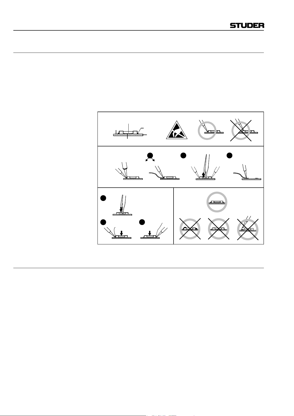
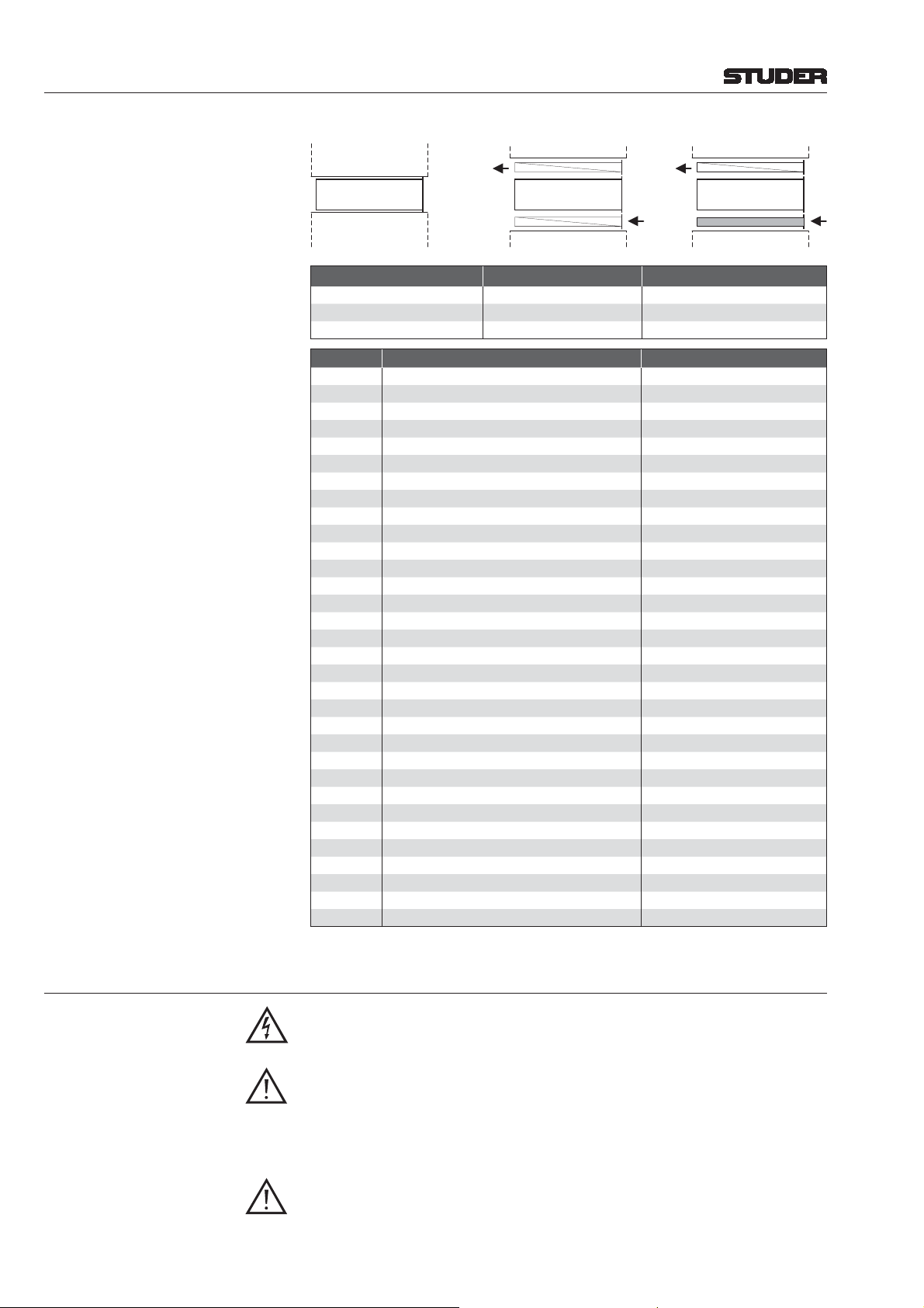
E1 SMD Components
Studer has no commercially available SMD components in stock for ser-
vice purposes. For repair, the corresponding devices have to be purchased
locally. The specifications of special components can be found in the service manual.
SMD components should only be replaced by skilled specialists using ap-
propriate tools. No warranty claims will be accepted for circuit boards that
have been damaged. Proper and improper SMD soldering joints are illustrated below.
Copper
Track
Dismounting
Soldering
Iron
SMD
Component
Adhesive
Desoldering
Iron
Solder
PCB
1
Desolder
Wick
Mounting
1
2
Solder
Ø 0.5...0.8 mm
3
Heating Time < 3 s per Side
Soldering Iron
32
Desolder
Wick
Heat and Remove Cleaning
Examples
F Disposal
Disposal of Packing Materials The packing materials have been selected with environmental and disposal
issues in mind. All packing material can be recycled. Recycling packing
saves raw materials and reduces the volume of waste.
If you need to dispose of the transport packing materials, please try to use
recyclable means.
Disposal of Used Equipment Used equipment contains valuable raw materials as well as materials that
must be disposed of professionally. Please return your used equipment via
an authorized specialist dealer or via the public waste disposal system, ensuring any material that can be recycled is.
Please take care that your used equipment cannot be abused. To avoid
abuse, delete sensitive data from any data storage media. After having disconnected your used equipment from the mains supply, make sure that the
mains connector and the mains cable are made useless.
VI
Page 9
Conformity
G Declarations of Conformity
G1 Class A Equipment - FCC Notice
This equipment has been tested and found to comply with the limits for a
Class A digital device, pursuant to Part 15 of the FCC Rules. These limits
are designed to provide a reasonable protection against harmful interference when the equipment is operated in a commercial environment. This
equipment generates, uses, and can radiate radio frequency energy and, if
not installed and used in accordance with the instruction manual, may
cause harmful interference to radio communications. Operation of this
equipment in a residential area is likely to cause harmful interference, in
which case the user will be required to correct the interference at his own
expense.
Caution: Any changes or modifications not expressly approved by the manufacturer
G2 CE Declaration of Conformity
vant information in this manual.
We,
Studer Professional Audio GmbH,
CH-8105 Regensdorf,
declare under our sole responsibility that the product
Studer D21m, Digital I/O System
(starting with serial no. 0001)
to which this declaration relates, according to following regulations of EU
directives and amendments
• Low Voltage (LVD):
73/23/EEC + 93/68/EEC
• Electromagnetic Compatibility (EMC):
89/336/EEC + 92/31/EEC + 93/68/EEC
is in conformity with the following standards or normative documents:
• Safety:
EN 60950-1:2000 (Class I equipment)
• Safety of laser products:
EN 60825-1:2004 + A11 + A2, EN60825-2:2000
• EMC:
EN 55103-1/-2:1996, electromagnetic environments E2 and E4.
Regensdorf, November 12, 2004
B. Hochstrasser, President M. Lienert, Manager R&D
VII
Page 10
Appendix
Appendix 1: Air Temperature and Humidity
General
Normal operation of the unit or system is warranted under the following
ambient conditions defined by EN 60721-3-3, set IE32, value 3K3.
This standard consists of an extensive catalogue of parameters, the most
important of which are: ambient temperature +5...+40 °C, relative humidity
5...85% (i.e., no formation of condensation or ice); absolute humidity
1...25 g/m³; rate of temperature change < 0.5 °C/min. These parameters are
dealt with in the following paragraphs.
Under these conditions the unit or system starts and works without any
problem. Beyond these specifications, possible problems are described in
Ambient Temperature
Units and systems by Studer are generally designed for an ambient tem-
• The admissible ambient temperature range for operation of the semi-
• The air flow through the installation must provide that the outgoing air
• Average heat increase of the cooling air shall be about 20 K, allowing
• In order to dissipate 1 kW with this admissible average heat increase, an
Example: A rack dissipating P = 800 W requires an air flow of 0.8 * 2.65 m³/min
• If the cooling function of the installation must be monitored (e.g. for fan
Frost and Dew
the following paragraphs.
perature range (i.e. temperature of the incoming air) of +5...+40 °C. When
rack mounting the units, the intended air flow and herewith adequate cooling must be provided. The following facts must be considered:
conductor components is 0 °C to +70 °C (commercial temperature range
for operation).
is always cooler than 70 °C.
for an additional maximum 10 K increase at the hot components.
air flow of 2.65 m³/min is required.
which corresponds to 2.12 m³/min.
failure or illumination with spot lamps), the outgoing air temperature
must be measured directly above the modules at several places within
the rack. The trigger temperature of the sensors should be 65 to 70 °C.
The unsealed system parts (connector areas and semiconductor pins) allow
for a minute formation of ice or frost. However, formation of dew visible
with the naked eye will already lead to malfunctions. In practice, reliable
operation can be expected in a temperature range above –15 °C, if the following general rule is considered for putting the cold system into operation:
If the air within the system is cooled down, the relative humidity rises. If it
reaches 100%, condensation will arise, usually in the boundary layer between the air and a cooler surface, together with formation of ice or dew at
sensitive areas of the system (contacts, IC pins, etc.). Once internal condensation occurs, trouble-free operation cannot be guaranteed, independent
of temperature.
Before putting into operation, the system must be checked for internal for-
mation of condensation or ice. Only with a minute formation of ice, direct
VIII
Page 11
Appendix
evaporation (sublimation) may be expected; otherwise the system must be
heated and dried while switched off.
A system without visible internal formation of ice or condensation should
be heated up with its own heat dissipation, as homogeneously (and subsequently as slow) as possible; the ambient temperature should then always
be lower than the one of the outgoing air.
If it is absolutely necessary to operate the cold system immediately within
warm ambient air, this air must be dehydrated. In such a case, the absolute
humidity must be so low that the relative humidity, related to the coldest
system surface, always remains below 100%.
Ensure that the enclosed air is as dry as possible when powering off (i.e.
before switching off in winter, aerate the room with cold, dry air, and remove humid objects as clothes from the room).
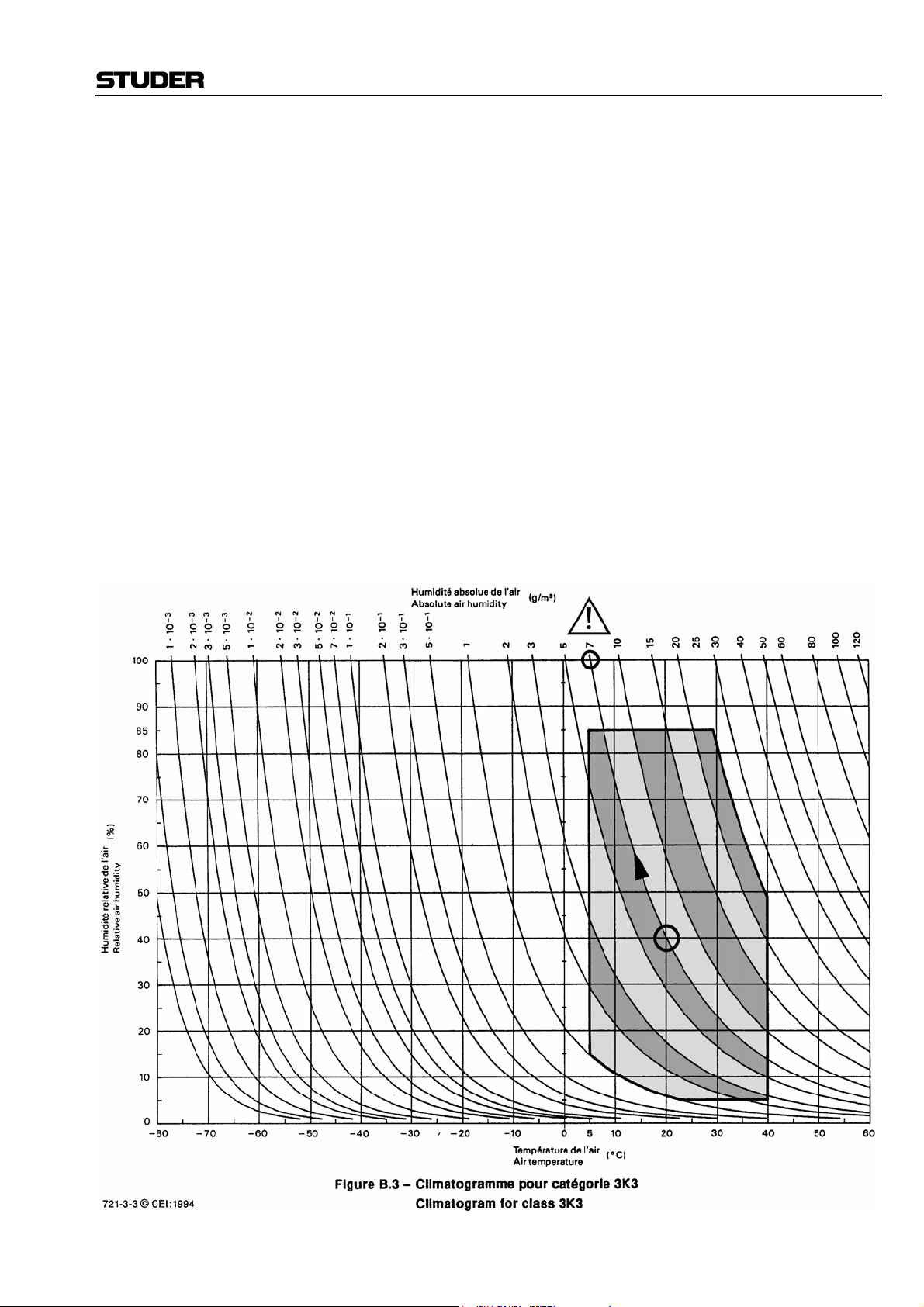
These relationships are visible from the following climatogram. For a con-
trolled procedure, thermometer and hygrometer as well as a thermometer
within the system will be required.
Example 1: An OB-van having an internal temperature of 20 °C and relative humidity
of 40% is switched off in the evening. If temperature falls below +5 °C,
dew or ice will be forming.
Example 2: An OB-van is heated up in the morning with air of 20 °C and a relative
humidity of 40%. On all parts being cooler than +5 °C, dew or ice will be
forming.
IX
Page 12
Appendix
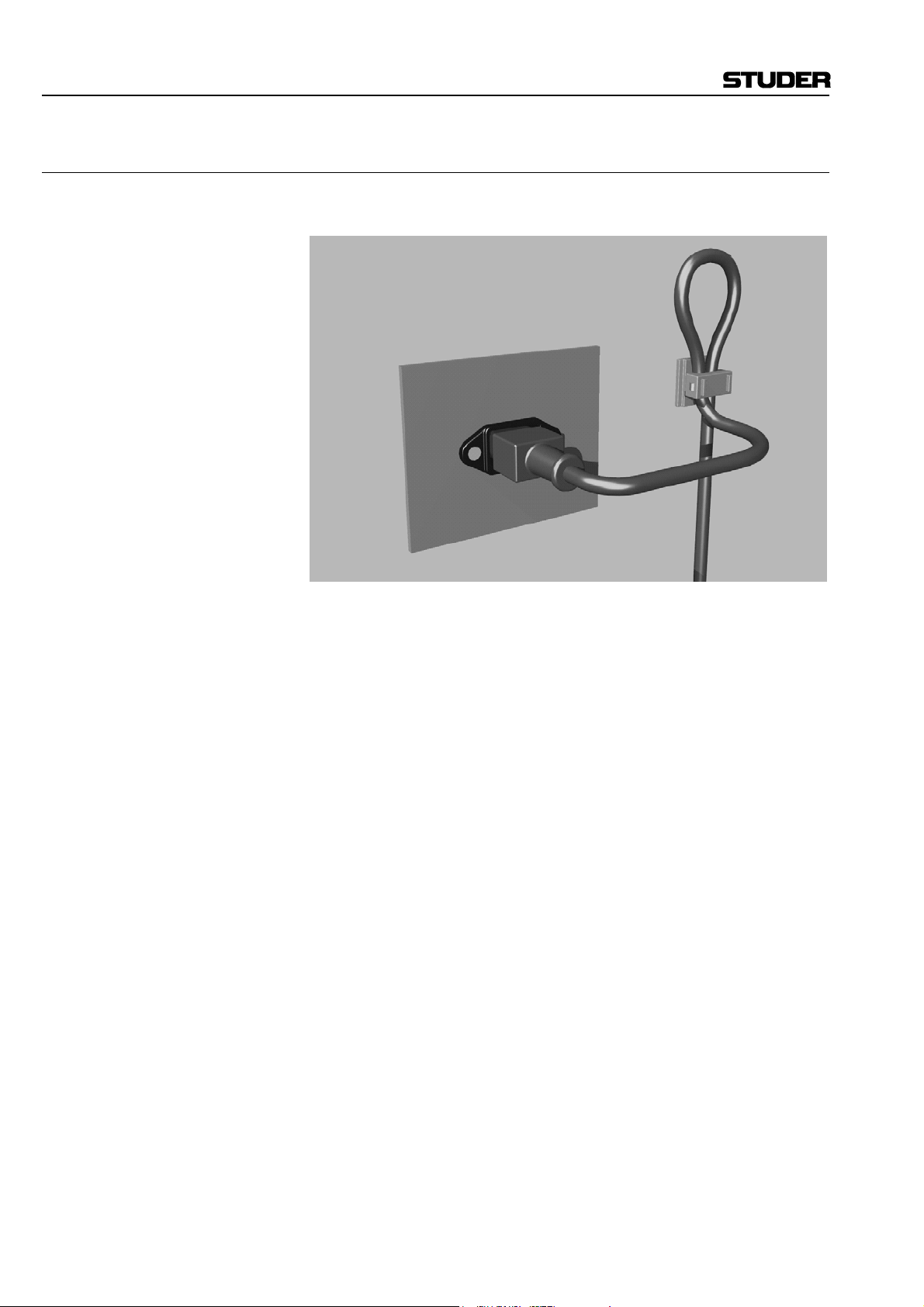
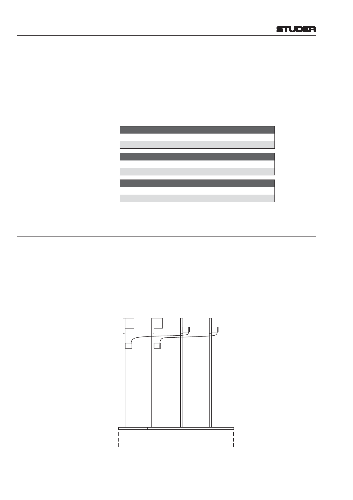
Appendix 2: Mains Connector Strain Relief
For anchoring connectors without a mechanical lock (e.g. IEC mains con-
nectors), we recommend the following arrangement:
Procedure: The cable clamp shipped with your unit is auto-adhesive. For mounting
please follow the rules below:
• The surface to be adhered to must be clean, dry, and free from grease,
oil, or other contaminants. Recommended application temperature range
is +20...+40 °C.
• Remove the plastic protective backing from the rear side of the clamp
and apply it firmly to the surface at the desired position. Allow as much
time as possible for curing. The bond continues to develop for as long as
24 hours.
• For improved stability, the clamp should be fixed with a screw. For this
purpose, a self-tapping screw and an M4 bolt and nut are included.
• Place the cable into the clamp as shown in the illustration above and
firmly press down the internal top cover until the cable is fixed.
X
Page 13
Appendix
Appendix 3: Software License
Use of the software is subject to the Studer Professional Audio Software
License Agreement set forth below. Using the software indicates your acceptance of this license agreement. If you do not accept these license terms,
you are not authorized to use this software.
Under the condition and within the scope of the following Terms and Con-
ditions, Studer Professional Audio AG (hereinafter “Studer”) grants the
right to use programs developed by Studer as well as those of third parties
which have been installed by Studer on or within its products. References
to the license programs shall be references to the newest release of a li-
Programs Covered by the Agreement
License Programs of Studer The following Terms and Conditions grant the right to use all programs of
Using the software indicates your acceptance of this license agreement. If
Programs of Third Parties Programs of third parties are all programs which constitute part of the Sys-
• The right to use third parties’ programs is governed by the License
• Studer shall accept no responsibility or liability for, and gives no war-
Right of Use
cense program installed at the Customer’s site.
Studer that are part of the System and/or its options at the time of its delivery to the Customer, as well as the installation software on the original data
disk and the accompanying documentation (“License Material”). In this
Agreement the word “Programs” shall have the meaning of programs and
data written in machine code.
you do not accept these license terms, you are not authorized to use this
software.
tem and/or its options at the time of delivery to the Customer but have not
been developed by Studer. The following conditions are applicable to programs of third parties:
Agreement attached hereto (if applicable), which is an integral part of
this Agreement. The Customer shall sign any and all License Agreements for all further programs of third parties installed on the system.
The Customer shall be deemed to have received all License Agreements
upon delivery of the system and/or its options.
ranties (express or implied) as to the programs of third parties. The Customer waives any and all claims versus Studer for any consequential
damages, which might occur due to defects of these programs.
Principle Studer grants the Customer the non-exclusive right to use the License Ma-
terial in one copy on the system and/or its options as laid down by the
Sales Agreement concluded between the parties and all Terms and Conditions which shall be deemed to form and be read and construed as part of
the Sales Agreement. This right is assignable according to the “Assignability” paragraph hereinafter.
Customized Configurations The Customer is not entitled to alter or develop further the License Mate-
rial except within the expressly permitted configuration possibilities given
by the software installed on the system or elsewhere. All altered programs,
including but not limited to the products altered within the permitted configuration possibilities, are covered by this License Agreement.
XI
Page 14

Appendix
Reverse Engineering Reverse engineering is only permitted with the express consent of Studer.
The consent of Studer can be obtained but is not limited to the case in
which the interface-software can not be provided by Studer. In any case
Studer has to be informed immediately upon complete or partial reverse
engineering.
Copying the License Material The Customer is entitled to make one copy of all or parts of the License
Material as is necessary for the use according to this Agreement, namely
for backup purposes. The Customer shall apply the copyright of Studer
found on the License Material onto all copies made by him. Records shall
be kept by the Customer regarding the amount of copies made and their
place of keeping. The responsibility for the original program and all copies
made lies with the Customer. Studer is entitled to check these records on
first request. Copies not needed anymore have to be destroyed immediately.
Disclosure of License Material The License Material is a business secret of Studer. The Customer shall not
hand out or in any way give access to parts or the complete License Material to third parties nor to publish any part of the License Material without
prior written consent of Studer. The Customer shall protect the License
Material and any copies made according to the paragraph above by appropriate defense measures against unauthorized access. This obligation of
non-disclosure is a perpetual obligation.
Third parties are entitled to have access to the License Material if they use
the License Material at the Customer’s site in compliance with this Agreement.
Under no circumstance are third parties entitled to have access to the instal-
lation software on the original data media. The Customer shall safeguard
the original data media accordingly.
Assignability The rights granted to the Customer according to this License Agreement
shall only be assignable to a third party together with the transfer of the
Rights to License Material
system and/or its options and after the prior written consent of Studer.
With the exception of the right of use granted by this License Agreement
all proprietary rights to the License Material, especially the ownership and
the intellectual property rights (such as but not limited to patents and copyright) remain with Studer even if alterations, customized changes or
amendments have been made to the License Material.
Studer’s proprietary rights are acknowledged by the Customer. The Cus-
tomer shall undertake no infringements and make no claims of any patent,
registered design, copyright, trade mark or trade name, or other intellectual
property right.
Warranty, Disclaimer, and Liability
For all issues not covered herewithin, refer to the “General Terms and
Conditions of Sales and Delivery” being part of the sales contract.
XII
Page 15

D21m System
CONTENTS
1 General .............................................................................................................................................................................1-1
1.1 Utilization for the Purpose Intended ...........................................................................................................................1-1
1.2 First Steps.................................................................................................................................................................... 1-1
1.2.1 Unpacking and Inspection..................................................................................................................................1-1
1.2.2 Installation..........................................................................................................................................................1-1
1.2.3 Adjustments, Repair, Cleaning ..........................................................................................................................1-2
2 Introduction .....................................................................................................................................................................2-1
2.1 System Philosophy......................................................................................................................................................2-1
2.2 The Frame and its Cards .............................................................................................................................................2-3
2.3 Hub Frame...................................................................................................................................................................2-4
2.4 Remote I/O Frame....................................................................................................................................................... 2-4
2.5 Vista Surveyor Software .............................................................................................................................................2-4
3 Applications......................................................................................................................................................................3-1
3.1 Local I/O Only (Located Close to Core)..................................................................................................................... 3-1
3.2 One I/O Box Within Long Distance............................................................................................................................3-1
3.3 Multiple I/O Boxes, Long Distance ............................................................................................................................3-2
3.4 Multiple Hubs, Multiple I/O Boxes, Long Distance...................................................................................................3-3
3.5 Shared I/O ...................................................................................................................................................................3-4
4 System Examples .............................................................................................................................................................4-1
4.1 System with Remote and Local I/O ............................................................................................................................4-1
4.2 System with Remote MIDI Connection......................................................................................................................4-2
5 Additional Information ................................................................................................................................................... 5-1
5.1 Mapping of I/O Cards to MADI and HD Link Channels ...........................................................................................5-1
5.2 Special Case: Microphone/Line Input Card................................................................................................................5-2
5.3 Analog Insert Cards ....................................................................................................................................................5-2
5.4 96 kHz Operation ........................................................................................................................................................ 5-3
5.5 Input/Output Delays....................................................................................................................................................5-4
5.5.1 Additional SFC Delay........................................................................................................................................ 5-5
5.5.2 Additional Processing Delay..............................................................................................................................5-5
5.6 The MADI Interface: 64 or 56 Channels?...................................................................................................................5-5
5.7 Standalone D21m I/O System.....................................................................................................................................5-6
5.8 Connection to the Performa Core................................................................................................................................5-8
Date printed: 30.08.07
Contents 0-1
Page 16

D21m System
6 D21m Modules .................................................................................................................................................................6-1
6.1 Available Cards ...........................................................................................................................................................6-1
6.2 Analog I/O Cards ........................................................................................................................................................6-2
6.2.1 Mic/Line In Card .....................................................................................................1.949.427..........................6-2
6.2.2 Analog Insert Card ..................................................................................................1.949.428..........................6-4
6.2.3 Line In Card ............................................................................................................1.949.421.......................... 6-6
6.2.4 Line Out Card .........................................................................................................1.949.420..........................6-8
6.3 Digital I/O Cards.......................................................................................................................................................6-10
6.3.1 AES/EBU I/O Cards ...........................................................1.949.422, 1.949.423, 1.949.424........................6-10
6.3.2 MADI I/O Cards .................................................................1.949.430, 1.949.431, 1.949.433........................6-13
6.3.3 ADAT I/O Cards ...................................................................................1.949.425, 1.949.429........................6-17
6.3.4 TDIF I/O Card .........................................................................................................1.949.426........................6-19
6.3.5 SDI InputCard..........................................................................................................1.949.441........................6-21
6.3.6 SDI I/O Card............................................................................................................1.949.442........................ 6-23
6.3.7 Dolby
6.3.8 CobraNet® Card .......................................................................................................1.949.445........................6-30
6.3.9 Aviom A-Net® Card .................................................................................................1.949.446........................6-32
6.3.10 EtherSound® Card ............................................................................................................................................ 6-34
®
E/Digital Decoder Cards ...........................................................1.949.443, 1.949.444........................6-25
6.4 Non-Audio I/O Cards................................................................................................................................................6-36
6.4.1 GPIO Card ..............................................................................................................1.949.435........................6-36
6.4.2 GPIO Card w. Relay Outputs ..................................................................................1.949.436........................6-38
6.5 HD Cards...................................................................................................................................................................6-40
6.5.1 HD Card S ...............................................................................................................1.949.412........................ 6-40
6.5.2 HD/RS422 Card ......................................................................................................1.949.415........................ 6-42
6.5.3 MADI HD Cards .................................................................1.949.411, 1.949.413, 1.949.414........................6-44
6.6 Serial/Merger Cards ..................................................................................................................................................6-48
6.6.1 Serial Card ..............................................................................................................1.949.437........................6-48
6.6.2 Serial Merger Card ..................................................................................................1.949.438........................6-50
6.6.3 Serial RJ45 Card .....................................................................................................1.949.439........................6-52
6.6.4 Dual Merger Card ...................................................................................................1.949.440........................6-54
6.7 Power Supply/Miscellaneous....................................................................................................................................6-56
6.7.1 Primary Power Supply .............................................................................................1.949.403........................ 6-56
6.7.2 LED/PSII PCB.........................................................................................................1.949.402........................ 6-57
6.7.3 Air Defl ector/Filter Unit ...........................................................................................1.949599........................6-58
6.7.4 Fan Unit ...................................................................................................................1.949.597........................6-58
6.7.5 Break-Out Boxes..............................................................................................................................................6-59
6.7.5.1 XLR Break-Out Box............................................................................................................................... 6-59
6.7.5.2 AES/EBU on BNC Break-Out Box ................................................................1.949.586........................6-59
6.7.5.3 GPIO Break-Out Box......................................................................................1.949.588........................6-60
6.7.6 Cables...............................................................................................................................................................6-61
6.8 Discontinued Components ........................................................................................................................................6-62
6.8.1 HD Card (not available for new systems)................................................................1.949.410........................ 6-62
Disclaimer
The information in this document has been carefully checked and is believed
to be accurate at the time of publication. However, no responsibility is taken
by us for inaccuracies, errors, or omissions, nor is any liability assumed for
any loss or damage resulting either directly or indirectly from use of the
information contained within it.
0-2 Contents
Date printed: 30.08.07
Page 17
D21m System
1 GENERAL
1.1 Utilization for the Purpose Intended
The D21m system is intended for professional use.
It is presumed that the unit is operated only by trained personnel. Servicing
is reserved to skilled technicians.
The electrical connections may be connected only to the voltages and signals
designated in this manual.
1.2 First Steps
1.2.1 Unpacking and Inspection
Your new system is shipped in a special packing which protects the units
against mechanical shock during transit. Care should be exercised when
unpacking so that the surfaces do not get marred.
Check the condition of the equipment for signs of shipping damage. If there
should be any complaints you should immediately notify the forwarding agent
and your nearest Studer distributor.
Please retain the original packing material because it offers the best protection
in case your equipment ever needs to be transported.
1.2.2 Installation
Primary Voltage: The power supply unit is auto-ranging; it can be used for mains voltages in
a range of 100 to 240 V
Power Connection : The attached female IEC 320/C13 mains cable socket has to be connected
to an appropriate mains cable by a trained technician, respecting your local
regulations. Refer to the “Installation, Operation, and Waste Disposal” chapter at the beginning of this manual.
Earthing : This equipment must be earthed, due to the mains input fi lter network be ing
connected to the mains earth .
Some consideration must be given to the earthing arrangement of the sy stem,
at the center of which is the frame. The frame is earthed to the mains earth
via the power supply . Ground loops may occur where signal processing equipment, patched to the frame, has its signal earth commoned to the equip ment
chassis.
Temperature Regulations: The unit must not be used in conditions of excessive heat or cold, near any
source of moisture, in excessively humid environments, or in positions where
it is likely to be subjected to vibration or dust. The ambient temperature range
for normal operation of the unit is +5...+40° C.
Under standard circumstances (open 19” frame) and an ambient temperature
between +5 and +40° C, the power dissipations listed below must not be
exceeded. Please note that these fi gures may change for special environments,
such as air-conditioned machine rooms, etc.
(continued on next page)
, 50 to 60 Hz.
AC
Date printed: 11.07.07
General 1-1
Page 18
D21m System
Closed Passive, 2 Vents Active, 1 Fan, 1 Vent
Rear Rear
Air
D21mD21m D21m
Air
Air
RearFront Front Front
Operating Mode Total Height Max. Power Dissipation
Closed 3 U 40 W
Passive, w. Vents 5 U 80 W
Active, w. Fan and Vent 5 U 200 W
Card No. Card Name Power Dissipation (approx.)
Backplane with power supply 10 W
1.949.427 Mic/Line in card 11 W
1.949.428 Analog insert card 2 W
1.949.421 Line In card 7 W
1.949.420 Line out card 7 W
1.949.422 AES/EBU card 3.5 W
1.949.423 AES/EBU card with input SFC 4.5 W
1.949.424 AES/EBU card with input/output SFC 5.5 W
1.949.430 MADI card, multi-mode fi bre 4 W
1.949.431 MADI card, single-mode fi bre 4 W
1.949.433 MADI card, twisted pair 4 W
1.949.425 ADAT I/O card 1.7 W
1.949.429 ADAT card, long-distance option 1.7 W
1.949.426 TDIF I/O card 1 W
1.949.441 SDI input card (16 channels) 4 W
1.949.442 SDI input/output card (8 channels) 4 W
1.949.443 Dolby
1.949.444 Dolby
1.949.445 CobraNet
1.949.446 Aviom A-Net
®
E/Digital decoder card, single 2.5 W
®
E/Digital decoder card, dual 4 W
®
card 4.5 W
®
card 2 W
1.949.435 GPIO card 3 W
1.949.436 GPIO card with relay outputs 2 W
1.949.412 HD card S 5 W
1.949.415 HD RS422 card 5 W
1.949.411 MADI HD card, multi-mode fi bre 5.5 W
1.949.413 MADI HD card, single-mode fi bre 5.5 W
1.949.414 MADI HD card, twisted pair 5.5 W
1.949.437 Serial card 0.2 W
1.949.438 Serial Merger card 0.6 W
1.949.439 Serial RJ45 card 0.2 W
1.949.440 Dual Merger card 1.2 W
- Ethersound card 3 W
Air
1.2.3 Adjustments, Repair, Cleaning
Danger: All internal adjustments as well as repair work on this product must be per-
formed by expert technicians!
Replacing the Supply Unit: The primary fuse is located within the power supply module and cannot be
changed. In case of failure, the complete power supply unit must be r eplaced.
Please ask your nearest Studer representative.
Cleaning: Do not use any liquids to clean the exterior of the unit. A soft, dry cloth or
brush will usually do.
For cleaning the display windows, most of the commercially available window
or computer/TV screen cleaners are suited. Use only a slightly damp (never
wet) cloth. Never use any solvent!
1-2 General
Date printed: 11.07.07
Page 19
D21m System
2 INTRODUCTION
The D21m I/O system provides very cost-effective inputs and outputs with
maximum fl exibility while maintaining the well-known Studer sound quality.
It is the fi rst Studer I/O system providing full 96 kHz operation. Different
I/O modules can be plugged into a frame, providing I/O systems tailor-made
to customer needs. And all this comes with an unequalled form factor. Full
redundancy is available starting from power supplies going up to redundant
interconnections and DSP cards.
Note: The examples in this document use the SCore. Although most applications
refer to this usage, the majority is also valid for use with the Performa core.
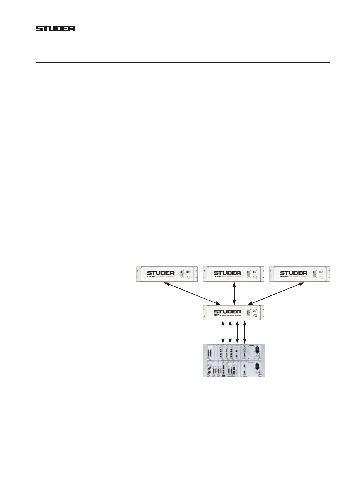
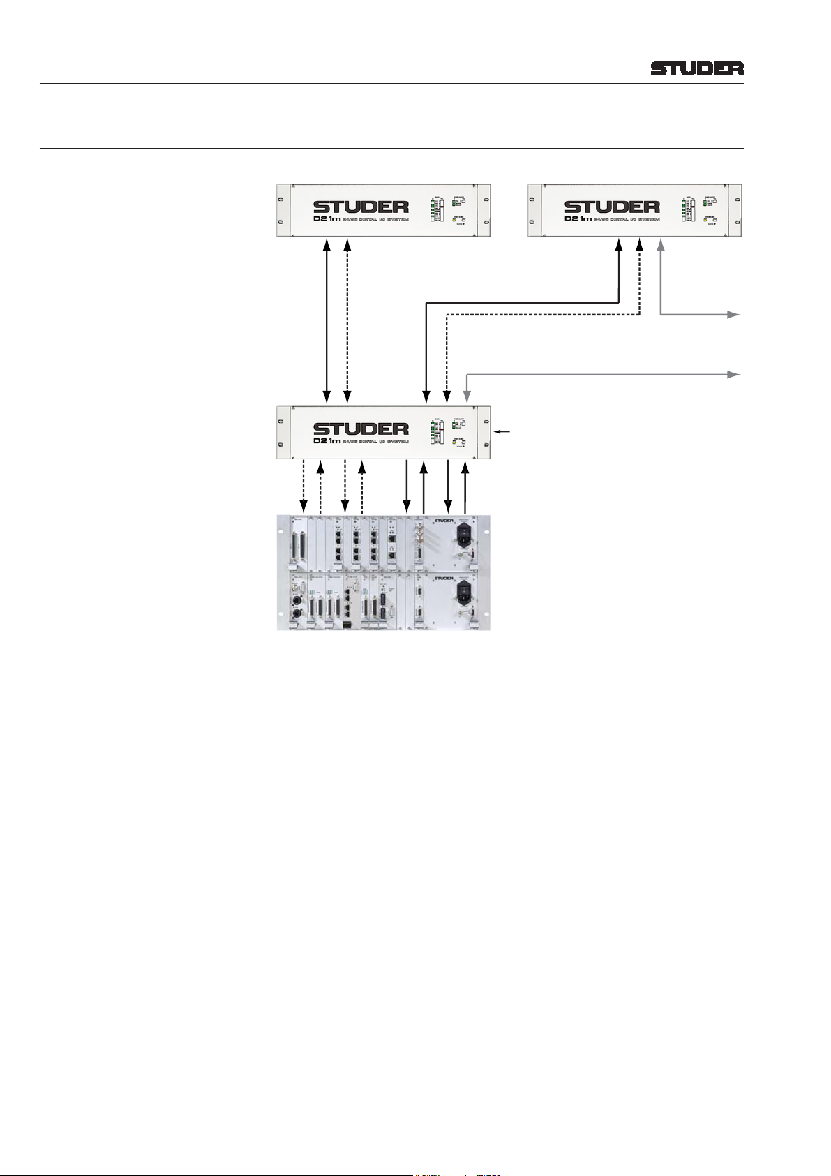
2.1 System Philosophy
When using the D21m I/O system the DSP core itself does not provide I/O,
but is connected to the fi rst D21m frame within the system (acting as a hub)
by using Studer proprietary “HD Link” technology. On the DSP core side,
the connection is made to the DSP card(s) directly. Link distance is limited
to 10 m, so the fi rst I/O box should be located close to the DSP core. From
that frame it is possible to run optical-fi ber MADI links to multiple places,
up to several kilometers away. By using this “star” architecture it is ensured
that a possible problem with one of the remote I/O boxes will not lead to a
general breakdown of the whole I/O system. A maximum of six remote I/O
boxes (stage boxes) may be connected to one hub frame. Should more I/O
channels be required then multiples of the “local frames” (hubs) may be used
within the system.
D21m Remote IO D21m Remote IO D21m Remote IO
MADI
MADI
D21m Hub & IO
Studer Proprietary HD Link
SCore &
I/O Frame
MADI
RS422 Link to Desk
Redundancy issues are regarded as highly important. It is therefore possible
to run any MADI links with redundant cables. The system is automatically
switching to the redundant connection in case the primary connection should
fail. For 96 kHz operation the second link can be used as a channel count
extension, transferring a total of 64 MADI channels even at 96 kHz sampling
frequency. The “redundant” MADI link may also be used for sharing an I/O
box between two consoles.
The MADI link between the fi rst D21m frame (hub) and the remote I/O boxes,
in addition, carries all control signals needed to control the microphone amplifi er cards, to interrogate the state (health) of any remote I/O card and to display it within the console’s system surveyor page. This is without sacrifi cing
Introduction 2-1Date printed: 11.07.07
Page 20

D21m System
any audio channels within the MADI link. Additionally, an RS422 signal can
be “tunneled” through the MADI connection. In this way e.g. a MIDI device
can be connected to the remote I/O box and fi nd the “extension” connector
on the hub frame next to the core again.
Notes: Unlike the Studer D19m I/O system, the D21m system is engineered as an
I/O system for use together with a Studer digital console, i.e., using the D21m
system as a “standalone” analog-to-digital or digital-to-analog converter only
works if MADI I/O is used on the digital side; for more information on this
subject please
Line input card and getting the A/D-converted signal out of the AES/EBU
card directly is not possible. This can be done only if the audio is routed with
a DSP core. Since the MADI signal to the D21m remote I/O box is used to
synchronize the unit, a stable, low-jitter MADI signal is necessary in order
to reach maximum audio quality. This is guaranteed by Studer equipment.
However, two I/O boxes can be interconnected using MADI, where one of
them must be switched to “Master” mode. In such a case up to 64 audio channels may be transmitted between two frames (applicable for MADI HD cards
1.949.411.23, 1.949.413.22, 1.949.414.20, or newer).
refer to chapter 5.7. Inserting, e.g., an AES/EBU card and a
2-2 Introduction Date printed: 11.07.07
Page 21
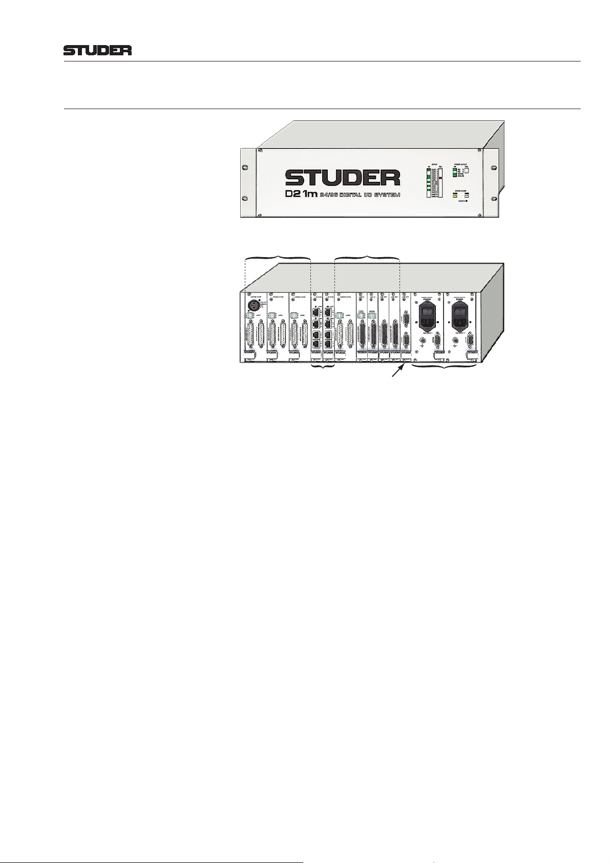
2.2 The Frame and its Cards
D21m System
Front View:
Rear View:
I/O Example:
3 Dual Card Slots
1...2 HD Link Cards
(Link to DSP Core)
I/O Example:
1 Dual-Slot Card
4 Single-Slot Cards
RS422 Serial
I/O Card
Main and Redundant
Power Supply
The 3 U frame provides 12 slots for I/O card insertion. Each card may provide
a different number of I/O channels, depending on its capabilities (e.g. a microphone card provides four channels of microphone inputs, while an ADAT card
provides 16 channels of inputs and outputs simultaneously). Some cards are
mechanically occupying two slots, and therefore a maximum of 6 doublewidth cards may be inserted into a frame. An overview of the dif ferent cards
currently available is given in chapter 6.1.
The frame hosts one or two “High Density Link” cards (short: HD Link),
providing the main audio connection to the DSP core. From the HD card(s)
the signals are redirected to the different types of I/O cards in the frame.
Therefore at least one HD card must be inserted in the frame.
The frame may be equipped with redundant power supplies, the status of
which can be displayed in the Vista console’s system surveyor page.
Please note that the rack mounting brackets may be installed either on the
front (as shown on the opposite page) or on the rear of the frame.
Introduction 2-3Date printed: 11.07.07
Page 22
D21m System
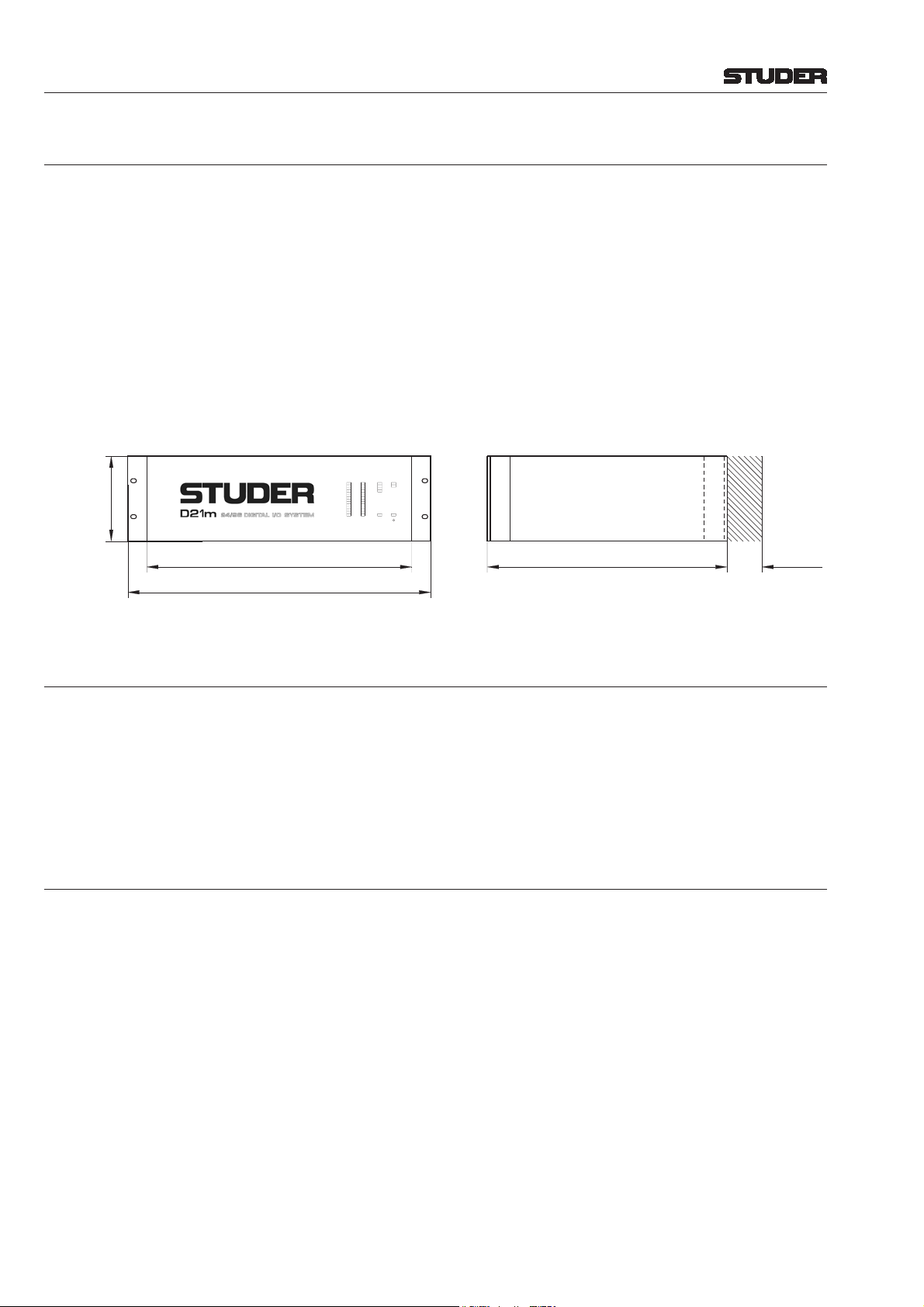
2.3 Hub Frame
The difference between a D21m frame acting as a hub or as a remote I/O
box is the type of HD Link and RS422 cards inserted. The HD Link card in
the hub frame hosts four RJ45 connectors for connection to the DSP core,
providing 192 channels (96 in case of the Performa core) of audio coming
from the DSP core through 2 cables into the frame (audio outputs), as well
as 192 channels from the frame through 2 cables into the DSP core (audio
inputs). The length of the high-density link cables must not exceed 10 meters
(30 feet).
If multiple remote I/O boxes are connected to one hub frame, more channels
need to be transferred to the DSP core. In this case it is possible to insert
a second HD card into the hub frame, expanding its capabilities to handle
384 inputs and outputs to the DSP core (192 outputs in case of the Performa
core).
CARDS
POWER SUPPLY
FAIL
IN FAILIN
CARD 1
PRI 1
CARD 2
PRI 2
CARD 3
DIGITAL
CARD 4
ANALOG
3 U
(133.5 mm)
426 mm
19" (482.4 mm)
CARD 5
CARD 6
HD CARD
HD CARD
CARD 7
CARD 8
CARD 9
SYSTEM CLOCK
CARD 10
96kHz 48kHz
CARD 11
CARD 12
RECONFIG
**
Connector
area,
approx.
380 mm
50 mm
* Rack mounting brackets may be installed on
front or rear of frame, depending on user's
preference.
2.4 Remote I/O Frame
The frame placed remotely is equipped with a special MADI HD card. This
version of the card is not equipped with the Studer proprietary high-density
link but with standard MADI optical interfaces. This format allows transferring 64 channels of inputs and outputs between the remote I/O box and the
hub frame simultaneously.
Frame dimensions are the same as shown in 2.3 above.
2.5 Vista Surveyor Software
The surveyor on the graphic controller (GC) screen of the Vista consoles will
indicate the whole I/O system, including the health state of each I/O card and
the power supplies. If the hardware found at startup time is not identical to
what the system expects, the user is asked whether the expectations should
permanently be changed or whether the user has temporarily changed the
I/O confi guration (such as having moved a remote I/O box to another place
for the current production). In both cases the surveyor application indicates
“green”, unless the user tells it to wait for the missing I/O components.
There is no need to tell the system which channel has a microphone preampli-
fi er included, since this detection is done automatically. However , it is necessary to defi ne which HD link of the hub frame is going to which PED21m card
within the Performa DSP core. This is done in a software menu accessible for
system administrators only.
2-4 Introduction Date printed: 11.07.07
Page 23
3 APPLICATIONS
oRS422 from Desk for
oSurveyor Information
p4...6 AES/EBU Outputs
mto Monitoring Frame
3.1 Local I/O Only (Located Close to Core)
I/O Frame
(One or
Multiple)
D21m System
96 Ch In
96 Ch In
96 Ch Out
SCore &
I/O Frame
3.2 One I/O Box within Long Distance
Remote
I/O Box
0...64 Ch Optical MADI
Hub
(and I/O)
96 Ch Out
96 Ch In
0...64 Ch Optical MADI
96 Ch In
96 Ch Out
(Redundancy)
96 Ch Out
Standard Dual Optical MADI Cable
with SC Type Connectors.
Max. 64 Channels, Includes
Mic Control Signals.
Studer Proprietary HD Link
(max. Distance 10 m)
I/O frame with Different
Types of I/O Cards
RS422 from Desk f
Surveyor Informati
and Mic Control
4...6 AES/EBU Out
to Monitoring Fra
Studer Proprietary HD Link
96 Ch In
(max. Distance 10 m)
96 Ch Out
SCore &
I/O Frame
96 Ch In
96 Ch Out
96 Ch In
4 × HD Link
96 Ch Out
96 Ch In
96 Ch Out
Notes: Both the remote I/O box and the local hub frame are standard D21m frames,
providing the possibility to insert any I/O cards available for the D21m I/O
system. The hub frame may therefore also be used for any audio I/O located
close to the DSP core.
Applications 3-1Date printed: 11.07.07
Page 24
D21m System
The channel count of the MADI link may be set in steps of eight channels
using card-internal DIP switches. In order to provide synchronization and
surveyor information it is necessary to provide a MADI link to and from the
remote I/O boxes at all times, even if the channel count should be set to 0.
The protocol switch on the front panel of the MADI I/O card may be set to
“64 channel” to allow maximum usage of the available channels. This switch
may only have to be set to “56 channel” protocol for operation with thirdparty MADI devices (in case no remote I/O box is connected to the MADI
I/O card).
If 64 channels of MADI transmission are required when working at 96 kHz,
the redundant MADI line can be used as a “channel extension” for transmitting the MADI channels 33-64 (29-56). This must be set accordingly with a
DIP switch on the MADI I/O card inserted in the hub frame.
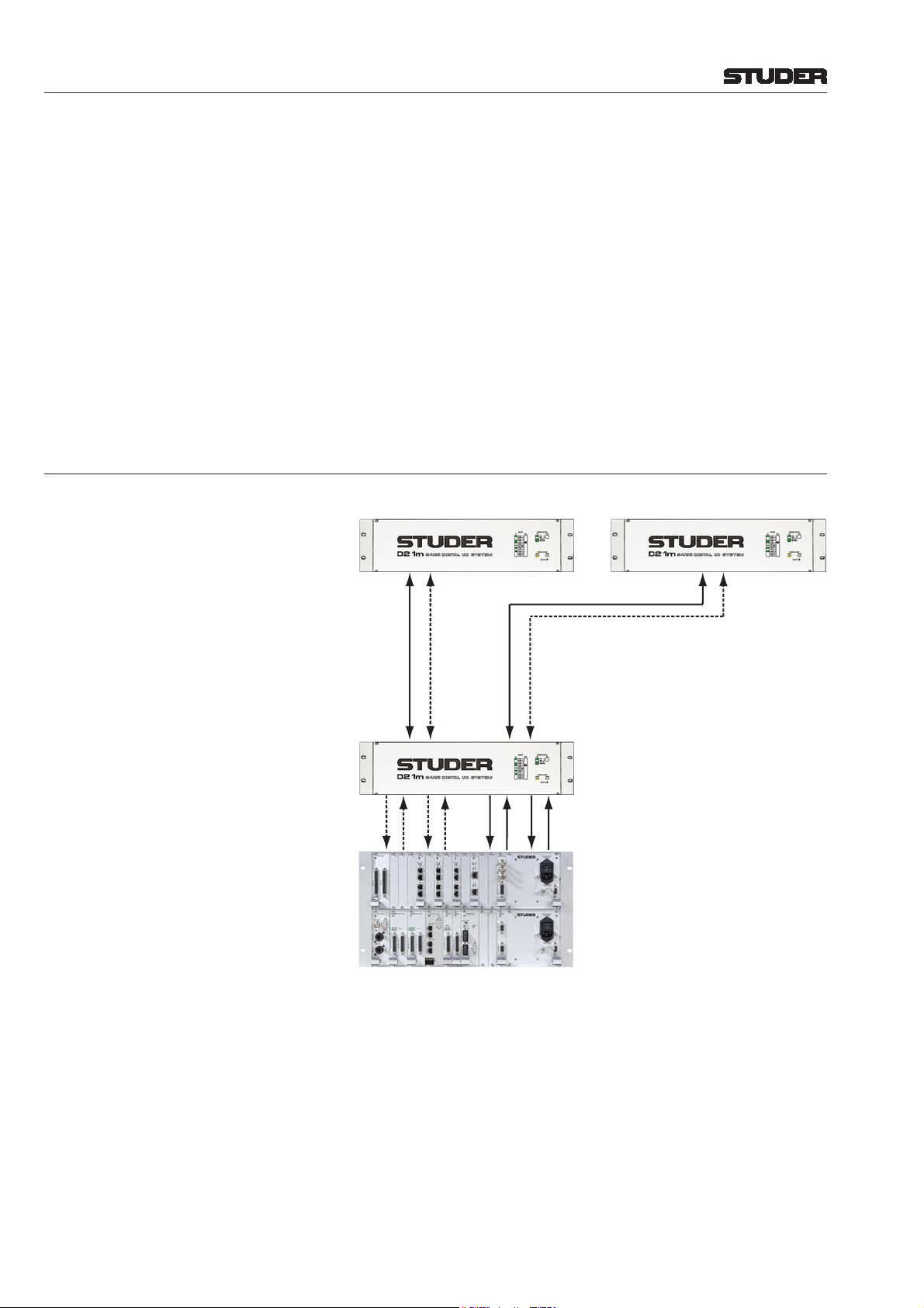
3.3 Multiple I/O Boxes, Long Distance
I/O Frames with Different
Remote I/O Box 1 ... ... Remote I/O Box 5
Types of I/O Cards
Remote
I/O Boxes
Hub
(and I/O)
SCore &
I/O Frame
0...64 Ch Optical MADI
0...64 Ch Optical MADI
RS422 from Desk for Surveyor
Information and Mic Control
96 Ch In
96 Ch In
96 Ch Out
96 Ch Out
(Redundancy)
96 Ch In
96 Ch Out
. . . .
Studer Proprietary HD Link
(max. Distance 10 m)
96 Ch In
96 Ch Out
Standard Dual Optical MADI Cable
with SC Type Connectors.
Max. 64 Channels, Includes
Mic Control Signals.
and Surveillance Information.
RS422 from Desk for Surveyor
Information and Mic Control
4...6 AES/EBU Outputs
to Monitoring Frame
Notes: Both the remote I/O box and the local hub frames are standard D21m frames,
providing the possibility to insert any I/O card available for the D21m I/O
system. The hub frame may therefore also be used for any audio I/O located
close to the DSP core.
Up to 5 remote I/O boxes can be connected to one hub frame. The last slot is
occupied with one ADAT card (or AES/EBU card in case of operation with
the Performa core) in order to provide I/O for monitoring and talkback of the
desk.
The channel count of the MADI link may be set in steps of eight channels
using card-internal DIP switches. In order to provide synchronization and
surveyor information it is necessary to provide a MADI link to and from the
remote I/O boxes at all times, even if the channel count should be set to 0.
3-2 Applications Date printed: 11.07.07
Page 25
D21m System
The protocol switch on the front panel of the MADI I/O card may be set to
“64 channel” allowing maximum usage of the available channels. This switch
may only have to be set to “56 channel” protocol for operation with thirdparty MADI devices (in case no remote I/O box is connected to the MADI
I/O card).
If 64 channels of MADI transmission are required when working at 96 kHz,
the redundant MADI line can be used as a “channel extension” for transmitting the MADI channels 33-64 (29-56). This must be set accordingly with a
DIP switch on the MADI I/O card inserted in the hub frame.
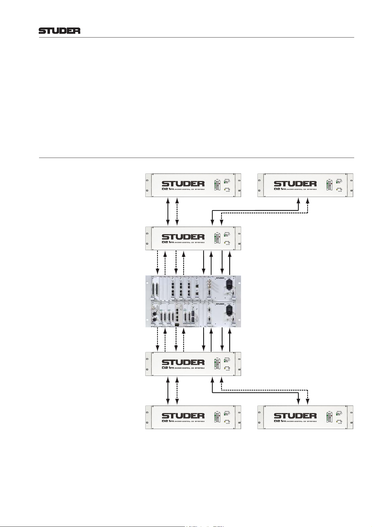
3.4 Multiple Hubs, Multiple I/O Boxes, Long Distance
I/O Frames with Different
Remote I/O Box 1 ... ... Remote I/O Box 5
Types of I/O Cards
Remote
I/O Boxes
Hub 1
(and I/O)
SCore &
I/O Frame
Hub 2
(and I/O)
0...64 Ch MADI
96 Ch In
96 Ch Out
96 Ch In
96 Ch Out
96 Ch In
96 Ch Out
96 Ch In
96 Ch Out
96 Ch In
96 Ch Out
96 Ch In
96 Ch Out
. . . .
Studer Proprietary HD Link
96 Ch In
(max. Distance 10 m)
96 Ch Out
Studer Proprietary HD Link
(max. Distance 10 m)
96 Ch In
96 Ch Out
0...64 Ch MADI
RS422 from Desk for Surveyor
Information and Mic Control
4...6 AES/EBU Outputs
to Monitoring Frame
RS422 from Desk for Surveyor
Information and Mic Control
0...64 Ch MADI
0...64 Ch MADI
Remote
I/O Boxes
Remote I/O Box 6 ... ... Remote I/O Box 11
I/O Frames with Different
Types of I/O Cards
. . . .
Notes: Both the remote I/O box and the local hub frames are standard D21m frames,
providing the possibility to insert any I/O card available for the D21m I/O
system. The hub frame may therefore also be used for any audio I/O located
close to the DSP core.
Up to 6 remote I/O boxes can be connected per hub frame, except in the fi rst
hub frame, where one slot is occupied with one ADAT card (or AES/EBU
Applications 3-3Date printed: 11.07.07
Page 26
D21m System
card in case of operation with the Performa core) in order to provide I/O for
monitoring and talkback of the desk.
The RS422 link for the second hub may be taken from the Vista desk by using
a further RS422 port.
The channel count of the MADI link may be set in steps of eight channels
using card-internal DIP switches. In order to provide synchronization and
surveyor information it is necessary to provide a MADI link to and from the
remote I/O boxes at all times, even if the channel count should be set to 0.
The protocol switch on the front panel of the MADI I/O card may be set to
“64 channel” to allow maximum usage of the available channels. This switch
may only have to be set to “56 channel” protocol for operation with thirdparty MADI devices (in case no remote I/O box is connected to the MADI
I/O card).
If 64 channels of MADI transmission are required when working at 96 kHz,
the redundant MADI line can be used as a “channel extension” for transmitting the MADI channels 33-64 (29-56). This must be set accordingly with a
DIP switch on the MADI I/O card inserted in the hub frame.
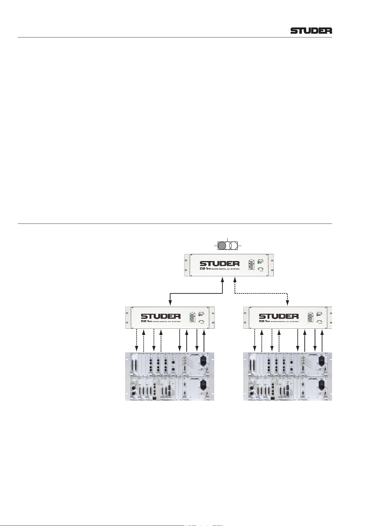
3.5 Shared I/O
Input Switch
on Front Panel of
MADI HD Card
Remote I/O Box
RS422 RS422
96 Ch In
96 Ch In
96 Ch Out
0...64 Ch Optical MADI
96 Ch In
96 Ch Out
96 Ch Out
redundant
12
0...64 Ch Optical MADI
Hubs
(and I/O)
96 Ch In
96 Ch Out
SCores &
I/O Frames
"Redundancy"
96 Ch In
96 Ch Out
96 Ch In
96 Ch Out
96 Ch In
96 Ch Out
96 Ch In
96 Ch Out
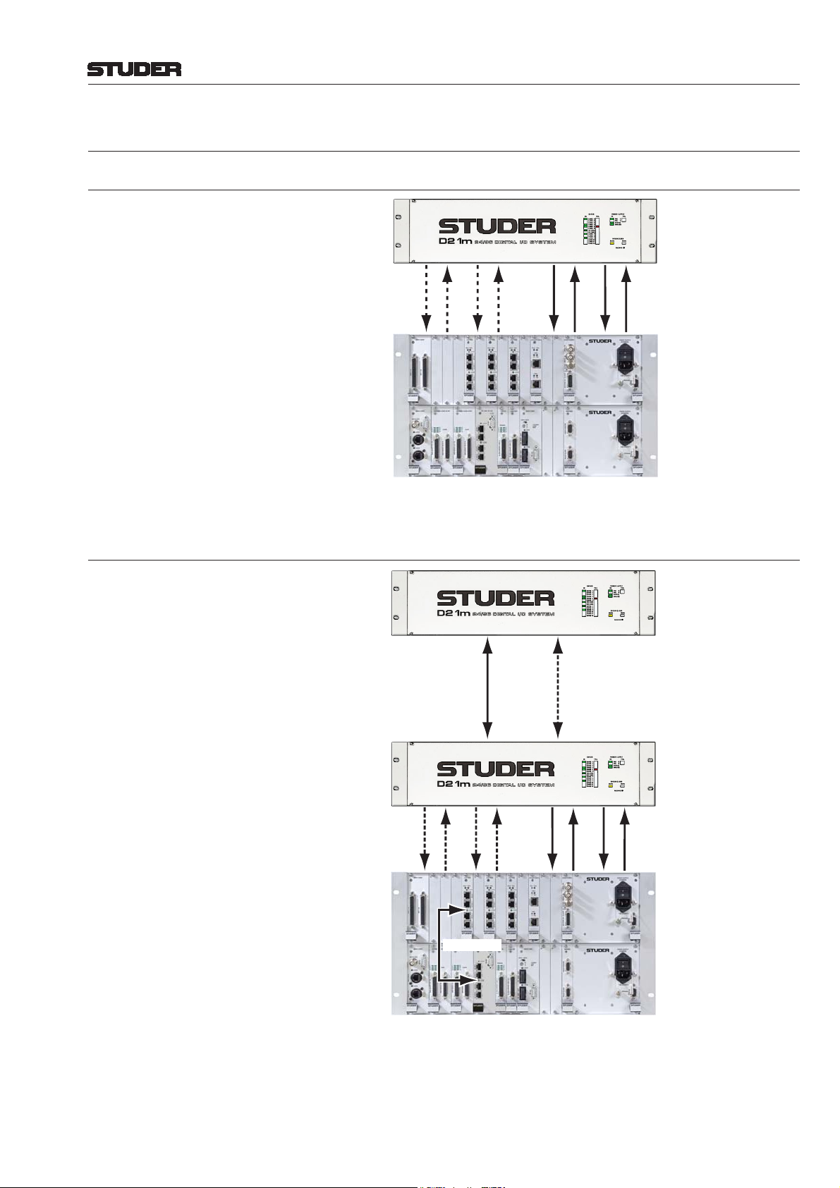
It is possible to connect one remote I/O box to two hubs or consoles at the
same time. This allows sharing of one box between two consoles. While the
audio inputs are fed to both consoles, the outputs on that I/O box may only
be fed by one of the two consoles at a time. An input selector switch on the
MADI HD card determines from which console the audio outputs are fed. At
the same time only the currently selected console will be able to display health
information in the surveyor. If the switch is set to “redundant”, the remote I/O
box jumps freely onto the second input in case the signal is lost on the main
input. Unless the signal is interrupted on the redundant input, too, the system
will not switch back to the main input in order to avoid undefi ned switching
in case of a bad MADI connection.
3-4 Applications Date printed: 11.07.07
Page 27
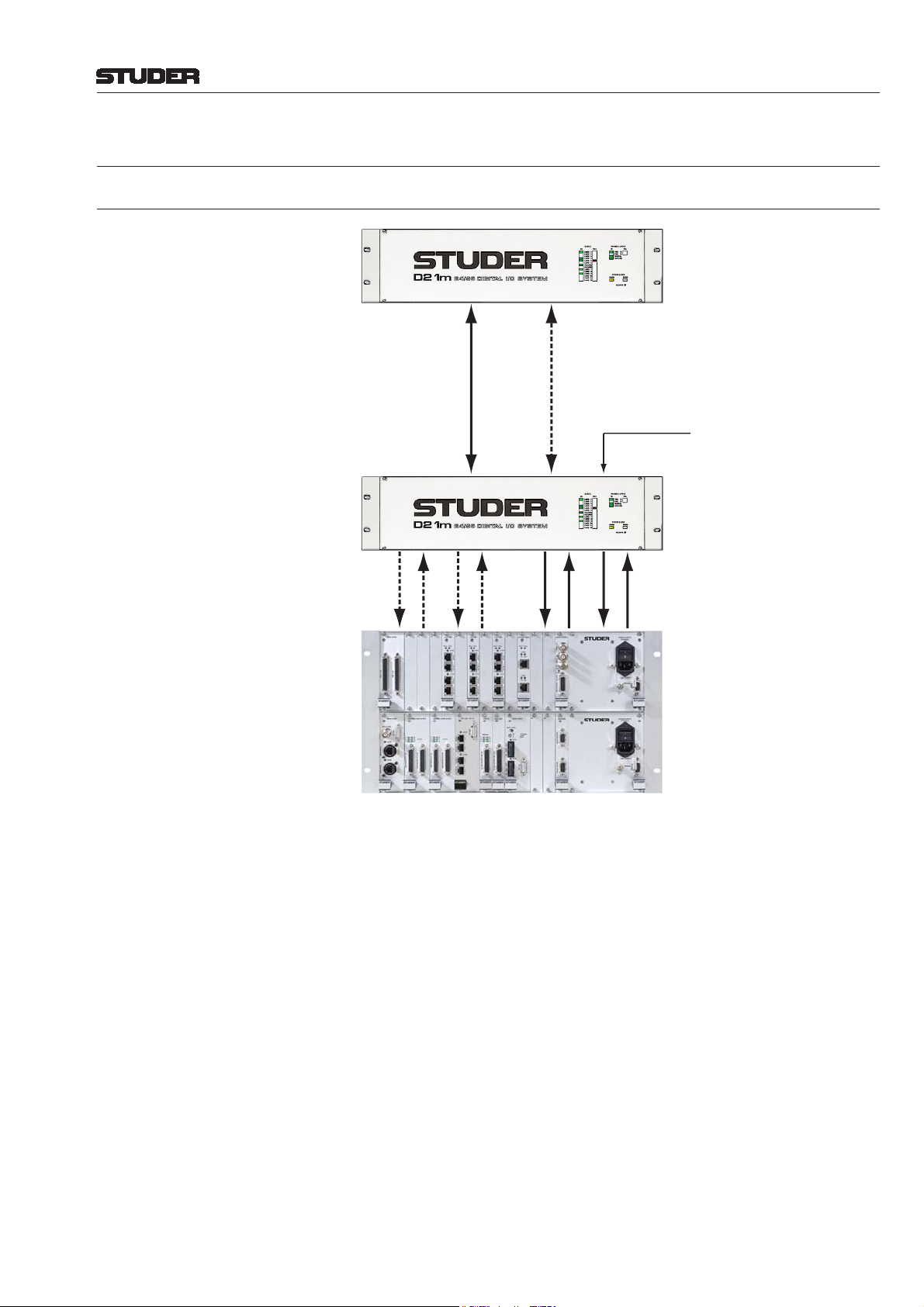
4 SYSTEM EXAMPLES
4.1 System with Remote and Local I/O
Remote
I/O Box
D21m System
Remote I/O Box, equipped w. e.g.:
• 44 Mic Inputs
• 8 Line Outputs (Returns)
or e.g.:
• 40 Mic Inputs
• 8 Line Inputs
• 8 Line Outputs (Returns)
or e.g.:
• 36 Mic Inputs
• 16 Ch ADAT In, 16 Ch Out
• 8 Line Inputs
• 8 Line Outputs
Hub
(and I/O)
96 Ch In
96 Ch Out
0...64 Ch Optical MADI
96 Ch In
96 Ch Out
(Redundancy)
0...64 Ch Optical MADI
96 Ch In
96 Ch In
96 Ch Out
96 Ch Out
RS422 for Mic Control
4...6 AES/EBU Outputs
to Monitoring Frame
Local I/O Hub, equipped with e.g.:
• 0...64 Ch MADI In/Out for
Stage Box Link
• 0...56 Ch MADI In/Out for
e.g. Multi-Track Recorder
• 16 AES/EBU In/Out (1 In and
5 Outs used for Monitoring)
• 32 Ch ADAT In/Out (Spare)
• 8 Mic Inputs
• 8 Line Inputs
• 8 Line Outputs
SCore &
I/O Frame
Notes: Some of the I/O cards are “double-width”, of which a maximum of 6 may be
fi tted in one D21m frame. When only using single-width cards, a maximum of
12 can be fi tted. Therefore, e.g. a maximum of 48 microphone inputs may be
fi tted in one (full) frame. If outputs are required as well, up to 44 microphone
inputs are possible since then at least one slot is used for an 8-channel line
output card.
Input and Output cards may be inserted in any order. The system is fi lling
up the MADI channels automatically, starting from the leftmost card subsequently to the right.
Since the MADI bandwidth can only be adjusted in steps of 8 channels, an
odd number of microphone cards (providing 4 inputs each) will result in 4
MADI channels without audio.
The MADI HD card versions 1.949.411.21/1.949.413.21 and newer support
operation with two MADI HD cards in one frame, extending the total channel count between the hub frame and the remote I/O box to 128. The same
channel count is reached in 96 kHz mode. For details please
r efer to chapter
6.5.3.
System Examples 4-1Date printed: 11.07.07
Page 28
D21m System
4.2 System with Remote MIDI Connection
I/O Frames with Different
Remote I/O Box 1 ... ... Remote I/O Box 5
Types of I/O Cards
Remote
I/O Boxes
Hub
(and I/O)
SCore &
I/O Frame
0...64 Ch Optical MADI
96 Ch In
96 Ch In
96 Ch Out
(Redundancy)
0...64 Ch Optical MADI
96 Ch In
96 Ch Out
96 Ch Out
. . . .
0...64 Ch Optical MADI, incl. MIDI
RS422 for Mic Control
4...6 AES/EBU Outputs
to Monitoring Frame
96 Ch In
96 Ch Out
MIDI Signal into
"AUX" RS422 of
Remote I/O Box
MIDI Signal into "AUX" RS422 of MADI I/O Card
Any serial signal, such as MIDI or Sony 9-pin (machine control) may be
transmitted through a MADI connection without losing any audio bandwidth
or microphone control of the remote I/O box. An RS422 connector labeled
“Aux” can be found on the MADI I/O card (hub frame side) as well as on the
serial card of the remote I/O frame. This card is located between slot 12 and
the power supplies. The required baud rate is set on the MADI I/O (local)
and MADI HD (remote) cards.
4-2 System Examples Date printed: 11.07.07
Page 29

D21m System
5 ADDITIONAL INFORMATION
5.1 Mapping of I/O Cards to MADI and HD Link Channels
The HD card is redirecting the audio channels from the different I/O cards
into the Studer proprietary HD link format (in case of a hub) or MADI (in
case of a remote I/O box). In order to design a complete I/O system, it is
mandatory to know which channels of the I/O cards end up being redirected
to which one of e.g. the 64 MADI channels. This will infl uence the way the
confi guration editor software is used and the labels are selected when starting
the operation of a new system.
General rule: The HD card fi lls in all channels starting from the left side of
the frame (slot 1) to the right. Input and output cards may therefore be mixed,
but their order dictates the “fi lling up” of MADI outputs from the frame. In
the same way the order of outputs from left to right is defi ning which MADI
inputs are being redirected to that card. The same rule applies for the Studer
proprietary HD link format.
The following example illustrates the rules within a complex I/O system:
AES I/O
Input Ch
Output Ch
MADI
Channel
1...16 AES/EBU
17...32 ADAT
33...40 Line In
41...48 Mic/Line In
Output Ch
16
16
From I/O Card
Input Ch
Line In
Line Out
ADAT I/O
8
16
8
16
AES I/O
Mic/Line In
4
16
16
MADI HD
Mic/Line In
4
48 Ch MADI
40 Ch MADI
MADI I/O
Mic/Line In
4
48
40
Remote I/O Box
Mic/Line In
4
MADI
Channel
1...16 AES/EBU
17...32 ADAT
33...40 Line Out
HD S
To I/O Card
Line Out
Line Out
8
8
Line In
8
PSU
(Red. PSU)
Hub Frame
PSU
(Red. PSU)
HD Link
Channel
1...16 AES/EBU
17...24 Mic/Line In
25...72 MADI
73...80 Line In
From
Hub I/O Card
HD Link (1)
Channel
17...48 MADI 1-32
HD Link (2)
80 Ch HD Link
Channel
72 Ch HD Links
SCore
To
Hub I/O Card
1...16 AES/EBU
1...8 MADI 33-64
9...24 Line Out
Additional Info 5-1Date printed: 11.07.07
Page 30
D21m System
5.2 Special Case: Microphone/Line Input Card
The smallest modularity of channels used up within the MADI and Core link
is eight. If an odd number of Mic/Line input cards is used, they should be
inserted in pairs, with the last card in an odd slot (no. 1, 3, 5...) This single
card will allocate 8 channels but only 4 of them will have audio. If a Mic/Line
input card pair uses Analog Insert cards, they should be placed in the next
double slot on the right, as shown in chapter 5.3.
For clearness, see the following examples:
Example 1:
10 Mic/Line Input cards (40 channels) 1...40
2 Line Input cards (16 channels) 41...56
Example 2:
9 Mic/Line Input cards (36 channels) 1...36 (37...40 no audio)
2 Line Input cards (16 channels) 41...56
Example 3:
9 Mic/Line Input cards (36 channels) 1...36 (37...40 no audio)
3 Line Input cards (24 channels) 41...64
Input Cards MADI Channel Usage
Input Cards MADI Channel Usage
Input Cards MADI Channel Usage
5.3 Analog Insert Cards
If you plan to equip the I/O box with Analog Insert cards, it is wise to avoid
channels without signal by installing two Mic/Line Input cards next to each
other, followed by two Analog Insert cards to their right. The Analog Insert
cards will be connected to “their” Mic/Line Input card by a ribbon cable. After
that, more Mic/Line Input cards may be inserted. This way all channels within
the hub-to-core link will be carrying audio, since there is always a group of
8 channels inserted next to each other. The two Analog Insert cards will not
use any channels within the link. The ribbon cables are lead through slots
provided in both the Mic/Line Input and Analog Insert cards.
(Front Panels)
Mic/Line Input
5-2 Additional Info Date printed: 11.07.07
Analog Insert
Page 31

D21m System
5.4 96 kHz Operation
D21m Frame: The D21m I/O system is fully supporting 96 kHz operation. For digital for-
mats, the following standards are supported:
AES/EBU 2 channels are sent over one cable, both at 48 kHz and 96 kHz, just by dou-
bling the clock frequency of the transmitted signal in 96 kHz operation.
MADI 0...64 channels are transmitted at 48 kHz (depending on the DIP switch set-
tings), and 0...32 channels are transmitted at 96 kHz. In the latter mode, the
clock frequency is doubled to 96 kHz, similar to the AES/EBU format. In
order to reach 64 channels of transmission between remote I/O boxes and the
hub frame at 96 kHz, the card’s redundant MADI connections can be selected
to transmit the “lost” half of the fi rst cable. This is done by a DIP switch on
both the MADI I/O and the MADI HD cards.
ADAT At 96 kHz, only 8 channels are transmitted (4 per optical interface).
TDIF At 96 kHz, only 8 channels are transmitted.
MADI HD If more than 32 channels are required in 96 kHz mode, the AUX interface
must be used as a “channel extension” to the main interface (i.e., DIP switch
#1 is OFF); it will then transmit channels 33...64 of the 96 kHz MADI signal.
Subsequently , MADI connection redundancy will not be available in 96 kHz
mode when exceeding a total channel count of 32 into or out of the remote
I/O box.
Performa Core: • For 96 kHz operation, the DSP core must only contain PE and PED21m cards
and a MemNet card type 1.950.621.xx (not 1.950.620.xx) or newer.
• In addition, the Performa core must contain a “Revision A” backplane.
• An external, high-quality (low-jitter) 96 kHz sync signal in AES/EBU format
must be provided.
• The session confi guration has to be re-calculated. Some I/O channels may
then have no audio but will still show up in the patch window . This is due to
the fact that some I/O cards (e.g. ADAT) will provide only half the number
of audio channels at 96 kHz.
48 kHz 96 kHz
I/O Card Confi guration
(from Left to Right)
AES/EBU
(16 Channels)
ADAT
(16 Channels)
Line Input
(8 Channels)
Mic/Line Input
(4 Channels)
Mic/Line Input
(4 Channels)
HD Link
Channel Usage
1...16
17...32
33...40
41...44
45...48
I/O Card Confi guration
(from Left to Right)
AES/EBU
(16 Channels)
ADAT
(16 Channels)
Line Input
(8 Channels)
Mic/Line Input
(4 Channels)
Mic/Line Input
(4 Channels)
HD Link
Channel Usage
1...16
17...32
(25...32 no audio)
33...40
41...44
45...48
Please note that the Studer proprietary HD link is providing 96 channels of
inputs to and 48 channels of outputs from the Performa cor e, in both 48 kHz
and 96 kHz operation.
(( zu: MADI HD, am Anfang des Abschnitts))
The MADI HD card versions 1.949.411.21/1.949.413.21 and newer support
operation with two MADI HD cards in one frame. This gives the possibility
to extend the total channel count between the hub frame and the remote I/O
box to 128. The same channel count is reached in 96 kHz mode.
Additional Info 5-3Date printed: 11.07.07
Page 32

D21m System
5.5 Input/Output Delays
Different DSP core types as well as the different I/O cards cause different
delays. Several facts require additional consideration. Total I/O delay is the
sum of the delays given in the tables below and depends on confi guration.
OutputInput
AES/EBU, local** AES/EBU, local**
I0*
AES/EBU, remote
I1*
Analog, local
I
2
Analog, remote Analog, remote
I
3
Processing
In - Out
P
0
In - Bus - Out
P
1
In - Bus - Group - Out
P
2
*/**see below
O0*
AES/EBU, remote
O1*
Analog, local
O
2
O
3
D21m I/O
(Independent of Core Type)
Block
I
*/** 0000
0
* 7 146 7 73
I
1
I
2
I
3
*/** 0000
O
0
O
* 483552
1
O
2
O
3
48 kHz 96 kHz
[smpl] [µs] [smpl] [µs]
38 792 38 396
45 938 45 469
28 583 28 292
32 667 33 344
* Enabled input and output SFCs each cause an additional delay, depending on
input and output sampling frequencies – for details refer to chapter 5.5.1.
** Local MADI, ADAT, and TDIF interfaces have approximately the same delay
as the AES/EBU interface (±1...2 samples)
Processing / Compact SCore
(OnAir 3000)
Processing / SCore Live
(OnAir 3000, Vista, Route 6000)
Block
P
0
P
1
P
2
Block
P
0
P
1
P
2
48 kHz
[smpl] [µs]
16 333
37 771
53 1104
48 kHz 96 kHz
[smpl] [µs] [smpl] [µs]
16 333 18 188
34 708 36 375
47 979 49 510
Processing / Performa Core
(Vista)
Block
P
0
P
1
P
2
48 kHz 96 kHz
[smpl] [µs] [smpl] [µs]
15 313 20 208
31 646 54 563
43 896 78 813
5-4 Additional Info Date printed: 11.07.07
Page 33

D21m System
5.5.1 Additional SFC Delay
Enabled input and output SFCs each cause an additional delay (D) depending
on the input and output sampling rates (f
Input and output delays can be calculated using the following formulas:
S_IN
and f
S_OUT
).
[1] f
S_IN
> f
S_OUT
: D =
16
f
S_IN
32
+ [s]
f
S_OUT
[2] f
S_OUT
> f
S_IN
: D =
48
f
S_IN
[s]
Examples: For a 96 kHz input signal and a 48 kHz system clock (i.e., the input SFC’s
output), the input delay is 40 output samples or 833 µs (formula [1]).
For a 48 kHz system clock (i.e., the output SFC’s input) and a 96 kHz output
signal, the output delay is 96 output samples or 1 ms (formula [2]).
5.5.2 Additional Processing Delay
Processing Block Compact SCore SCore Live*** Comment
Limiter
Monitoring Module
TB Sum / Monitor Sum
Core-Core MADI Link
Insert Send
Output Sum*
Program Output**
Assignable Process
1 ms - if active
1 sample -
5 samples 5 samples
17 samples 17 samples
5 samples 5 samples
16 samples 13 samples
5 samples 5 samples
- 5 samples
Signal path,
e.g. to phones out
e.g. fader,
stereo -> mono
* Delay from a channel input to a summing output
** Delay from a summing output to a master/group output
*** Independent of the sampling frequency (48 or 96 kHz)
5.6 The MADI Interface: 64 or 56 Channels?
The D21m I/O system is fully supporting the MADI protocol of 56 channels
(standard MADI) as well as 64 channels (not supported by all third-party
MADI devices). Protocol selection is done on the front panel switch of the
MADI I/O card. Between a D21m hub and a D21m remote I/O box always
64-channel format should be selected, since the MADI HD card in the remote
I/O box expects the 64 channel protocol.
Note: The protocol switch on the front panel of the MADI I/O card is not related to
the channel count setting by the DIP switch on the card itself. In other words,
you possibly only use 32 MADI channels (determined by DIP switch), but
you nevertheless have to select whether the standard MADI protocol (“56
channels”) or the extended version is used. The correct setting of the protocol
switch on the front panel is purely depending on the third-party equipment
connected to that MADI interface.
Additional Info 5-5Date printed: 11.07.07
Page 34

D21m System
5.7 Standalone D21m I/O System
Previously only available for Studer digital mixing consoles, the D21m I/O
system is now opened up for use with any audio equipment. With the introduction of the D21m remote control software, the microphone amps and A/D
converters become available to a wide range of applications, such as recording, broadcast, and live sound.
A D21m I/O frame can be connected to any 3rd-party device using its optical
MADI interface. The remote control software runs on a PC, connected to the
I/O frame over an additional RS422 serial connection. This software may
even rut at the same time as DAW software.
The I/O frame itself is highly modular, and it is possible to select from a
variety of I/O cards. Thanks to the two MADI interfaces the D21m I/O keeps
its channel count high even in 96 kHz mode. This makes this product ideal
for any use with a Digital Audio Workstation (DAW). In 48 kHz mode the
second MADI interface interface serves as a digital split output for feeding
any additional audio device or as a redundant audio link.
In facilities containing Studer Vista consoles, the investment is broadened by
the extreme versatility of the D21m stage boxes. One day they can be used
on stage, connected to the Studer console, and the next day in the recording
studio in order to bring superb audio quality to lower-cost recording equipment.
Remote Software The control software is an application running under Microsoft Windows
XP on any regular PC with an RS422 serial port. The software automatically detects the connected hardware and allows controlling the microphone
amplifi er’s parameters, such as phantom power , high-pass fi lter, soft clipping,
analog insert, gain, labeling and color coding the inputs, and stereo linking
two subsequent channels.
These parameters may be stored and recalled using snapshot fi les. Spare
inputs may be hidden from the screen, while the used ones can be arranged
in any order. Operating speed is maximized by the ability to group inputs in
a Vista-like way (“ganging”).
MADI Interface The MADI IF of the D21m frame supports both the standard MADI protocol
with up to 56 audio channels as well as the extended protocol with 64 channels. Protocols are selected on the front panel of the frame.
5-6 Additional Info Date printed: 11.07.07
Page 35

D21m System
The frame acts as a clock slave and synchronizes to the optical MADI signal.
It therefore automatically detects the clock rate of the connected audio device.
Supported clock rates are 44.1, 48, 88.2, and 96 kHz.
In 44.1 and 48 kHz mode the two MADI interfaces work in parallel. One of
them may be used as a digital split output or for redundancy . In 88.2 or 96 kHz
mode the MADI IF only transmits a maximum of 32 channels. Therefore the
second MADI IF is used to bring back the original total channel count.
Application Examples:
MADI
MADI
RS422
Windows Laptop
RS422
Digital Audio Workstation
MADI
RS422 MADI
Windows Digital Audio Workstation
Recording with Windows DAW Recording with non-Windows DAW
RS422
Other
Analog
Split Outputs
Windows DAW
Live recording with 3
3rd-Party
Digital Console
rd
-party digital PA console Live recording with analog PA console
Windows DAW
Analog Console
Additional Info 5-7Date printed: 11.07.07
Page 36

D21m System
5.8 Connection to the Performa Core
The Performa core is connected to the D21m I/O System in a similar way as
the SCore. The main difference is that the HD link connection from the core
towards the D21m I/O frame only carries up to 48 channels (at both 48 and
96 kHz). In order to implement a correct mapping of the I/O cards’ channels
to the HD Link, the “Performa Mode” switch (or jumper) must be ON on the
HD cards. In the Performa core, use of the PE-D21m card (1.950.606.22) is
mandatory . Each card implements one HD link input with up to 96 channels,
and one HD link output with up to 48 channels.
Application Examples:
Local I/O Only (located close to the core)
I/O Frame
(One or
Multiple)
RS422 from Desk for
Surveyor Information
and Mic Control
4...6 AES/EBU Outputs
to Monitoring Frame
96 Ch In
96 Ch In
48 Ch Out
Performa
DSP Core
(PE and
PE D21m
Cards
Remote I/O Box (within long distance)
Remote
I/O Box
0...64 Ch Optical MADI
Hub
(and I/O)
48 Ch Out
96 Ch In
96 Ch In
48 Ch Out
48 Ch Out
Standard Dual Optical MADI Cable with
SC Type Connectors. Max. 64 Channels,
Includes Mic Control Signals and
Surveillance Information.
(Redundancy)
0...64 Ch Optical MADI
Studer Proprietary HD Link
(max. Distance 10 m)
I/O frame with Different
Types of I/O Cards
RS422 from Desk for
Surveyor Information
and Mic Control
4...6 AES/EBU Outputs
to Monitoring Frame
96 Ch In
48 Ch Out
96 Ch In
48 Ch Out
96 Ch In
48 Ch Out
Studer Proprietary HD Link
96 Ch In
(max. Distance 10 m)
48 Ch Out
Performa
DSP Core
(PE and
PED21m
Cards
5-8 Additional Info Date printed: 11.07.07
Page 37

6 D21m MODULES
6.1 Available Cards
D21m System
Name
I/O
Format
# of Console
Input Channels
# of Console
Output Channels
Connector Type Width (Slots) Order No.
Analog I/O Cards
Mic/Line Input (incl. Dir. Outs)
Analog Insert *
Analog Line In
Analog Line Out
Mic/Line 4 (4 Dir. Outs) D25 f single 1.949.427
Line 4 4 D25 f single 1.949.428
Line 8 – D25 f single 1.949.421
Line – 8 D25 f single 1.949.420
Digital I/O Cards
AES I/O (no SFC)
AES I/O (SFC on Inputs)
AES I/O
(SFC on Inputs and Outputs)
MADI I/O ***/****
ADAT I/O
TDIF I/O
SDI Input
SDI I/O
®
Dolby
E/Digital Decoder
CobraNet
Aviom A-Net
EtherSound
®
I/O
®
Output
®
I/O ***
AES/EBU 8 stereo (16 mono) 8 stereo (16 mono) 2 × D25 f
AES/EBU 8 stereo (16 mono) 8 stereo (16 mono) 2 × D25 f
AES/EBU 8 stereo (16 mono) 8 stereo (16 mono)
MADI
ADAT 16 at 48 kHz (8 at 96 kHz) 16 at 48 kHz (8 at 96 kHz) TOSLINK (optical) single
TDIF 16 at 48 kHz (8 at 96 kHz) 16 at 48 kHz (8 at 96 kHz) 2 × D25 f
SDI /
HD SDI
SDI /
HD SDI
AES/EBU
CobraNet 32 32 2 × RJ45 single 1.949.445
A-Net – 16 RJ45 single 1.949.446
EtherSound 64 64 3 × RJ45 double ** -
64 at 48 kHz (32 with red.,
64 without red. at 96 kHz)
8 – 2 × BNC single 1.949.441
8 8 4 × BNC single 1.949.442
8
16
64 at 48 kHz (32 with red.,
64 without red. at 96 kHz)
2 stereo (4 mono)
4 stereo (8 mono)
2 × D25 f;
ext. sync XLR
SC (optical)
SC (optical)
2 × RJ45
D15 f single
double **
double **
double **
double **
double **
1.949.422
1.949.423
1.949.424
1.949.430
1.949.431
1.949.433
1.949.425
1.949.429
1.949.426
1.949.443
1.949.444
Non-Audio I/O Cards
GPIO w. Open-Collector Outp.
GPIO w. Relay Outputs
GPIO 16 16 2 × D25 f
GPIO 16 16 2 × D37 f
double **
double **
1.949.435
1.949.436
HD Cards
HD S
HD RS422
MADI HD
HD Link max. 96 max. 96 4 × RJ45 single 1.949.412
HD Link +
RS422
MADI
max. 96 max. 96 4 × RJ45, D9 f
64 at 48 kHz (32 with red.,
64 without red. at 96 kHz)
64 at 48 kHz (32 with red.,
64 without red. at 96 kHz)
SC (optical)
SC (optical)
RJ45
double **
double **
1.949.415
1.949.411
1.949.413
1.949.414
Serial / Merger Cards
Serial
Serial Merger
Serial RJ45
Dual Merger RJ45
RS422 - - D9 f single 1.949.437
RS422 - - 2 × D9 f single 1.949.438
RS422 - - RJ45 single 1.949.439
RS422 - - 4 × RJ45 single 1.949.440
Supply / Miscellaneous
Primary Power Supply Unit
LED/PSII PCB
Extender Card
Air Defl ector/Filter Unit
Fan Unit
XLR Break-Out Boxes
AES/EBU on BNC Break-Out Box
GPIO Break-Out Box
* The Analog Insert card belongs to the Mic/Line Input card to its left. It does not communicate with the HD card. The insert send signal is always present and
may be used as an additional direct output. The insert return is activated by the software (console).
** Double-width cards must be inserted into odd slot numbers (e.g. slots 1, 3, 5…).
*** The number of channels transmitted to and from a card may be defi ned in steps of 8 channels by using DIP switches on the card.
**** Regardless of the number of channels defi ned with the DIP switches, a switch on the front panel switches the MADI protocol between the standard 56-
channel format and the extended 64-channel format. Therefore this switch may have to be set to “56 channel” protocol in order to operate correctly with
third-party MADI devices. In this case the number of channels set internally should not exceed 56.
1.949.404
1.949.402
1.949.408
1.949.599
1.949.597
div.
1.949.586
1.949.588
D21m Modules 6-1Date printed: 27.10.08
Page 38

D21m System
6.2 Analog I/O Cards
6.2.1 Mic/Line In Card ( and ) 1.949.427
Four analog microphone/line inputs, electronically balanced, with 24 bit,
44.1/48/88.2/96 kHz delta-sigma A/D converters (mic/line sensitivity, gain
setting in 1 dB steps, low-cut fi lter, soft clipping and 48 V phantom power on/
off controlled by console software); four analog split outputs, electronically
balanced. Green “signal present” and yellow “phantom power” indicators
per channel. Inputs and split outputs on standard 25-pin D-type connector
(female).
Input sensitivity (for 0 dB
) –60…+26 dBu
FS
Input impedance 1.8 kΩ
Split out gain (input sensitivity –60…+3 dBu) 0 dB
(input sensitivity +4…+26 dBu) –20 dB
Split out impedance 50 Ω
Equivalent input noise (Ri 200 Ω, max. gain) –124 dBu
Crosstalk (1 kHz) < –110 dB
Frequency response (30 Hz...20 kHz) –0.2 dB
THD&N (35 Hz...20 kHz, –1 dB
(1 kHz, –30 dBFS, min. gain) < –111 dB
(input level 6 dBu, min. gain) < –107 dB
, min. gain) < –97 dB
FS
FS
FS
FS
CMRR (30 Hz...20 kHz, all gain settings) > 55 dB
(1 kHz, input sensitivity –10...+26 dBu for 0 dB
) typ. 100 dB
FS
Low-cut fi lter 75 Hz / 12 dB/oct.
Input delay (local) 38 samples (0.79 ms @ 48 kHz)
(remote) 45 samples (0.94 ms @ 48 kHz)
Current consumption (7 V) 0.2 A
(±15 V) 0.25 A
Operating temperature 0...40° C
Insert Connector
INS
INS
A
D
Mic/Line In 1
Split out 1
Mic/Line In 2
Split out 2
Sensitivity
–60...+26 dBu
0 dB*
–20 dB*
0 dB*
–20 dB*
Mic/Line In 3
Split out 3
Mic/Line In 4
Split out 4
48 V Phantom Pwr
0 dB*
–20 dB*
0 dB*
–20 dB*
Sensitivity Control
Control Logic
* 0 dB for input sensitivity –60...+3 dBu, –20 dB for input sensitivity +4...+26 dBu
High-Pass Filter Insert Control
INS
INS
A
Backplane Connector
D
6-2 D21m Modules Date printed: 25.09.07
Page 39

D21m System
RA1
RA2
RA3
RA4
RA1...4: Factory Setting (Level Fine-Adjustment)
LEDs: PHANTOM 1...4 For each channel a yellow LED indicates if the pantom supply is on.
SIGNAL 1...4 For each channel a green LED indicates if input signal is present; its bright-
ness is a rough indication of the signal level.
Alignment: RA1...4 Please note that the input level trimmer potentiometers are factory-set. They
need to be adjusted only after havin
Select 15
dBu input sensitivity. Feed an analog signal with a level of +6 dBu
g repaired the card.
to one of the analog inputs. Measure the digital output level either on the
MADI output or, after routing through the core, on one of the AES/EBU
outputs. Adjust the level with the corresponding FINE ADJUST trimmer
potentiometer to –9 dB
.
FS
Connector Pin Assignment: (25-pin D-type, female)
Pin Signal Pin Signal
1 CH 4 split out + 14 CH 4 split out –
2 CH 4 split out GND 15 CH 3 split out +
Solder/Crimp View
(or Socket View)
25
14
13
1
3 CH 3 split out – 16 CH 3 split out GND
4 CH 2 split out + 17 CH 2 split out –
5 CH 2 split out GND 18 CH 1 split out +
6 CH 1 split out – 19 CH 1 split out GND
7 CH 4 in + 20 CH 4 in –
8 CH 4 in GND 21 CH 3 in +
9 CH 3 in – 22 CH 3 in GND
10 CH 2 in + 23 CH 2 in –
11 CH 2 in GND 24 CH 1 in +
12 CH 1 in – 25 CH 1 in GND
13 n.c.
Important! If wired correctly, the microphones are isolated from the D21m chassis. The
circuit inside the microphone takes its supply from pins 2 and 3 (+ and –) for
the positive, and from pin 1 (GND) for the negative reference. If a patch bay
is implemented, GND (pin 1 on XLR connector) of each microphone input
must be connected to its corresponding GND pin, but not to the chassis. If
chassis instead of GND is used as negative reference for a microphone, it can
occur that the GND net of the D21m is pulled towards –48 V. This causes the
HD link receivers not to work correctly or to be damaged, depending on the
type and number of microphones connected.
As a workaround, GND and chassis may be connected inside the D21m frame.
In cases where currents fl ow between the chassis nets of multiple devices, the
analog signals can degrade in quality (e.g. perceivable as hum).
D21m Modules 6-3Date printed: 25.09.07
Page 40

D21m System
6.2.2 Analog Insert Card ( and ) 1.949.428
This card is intended for use with a D21m Mic/Line In card and features four
electronically balanced analog inserts. The insert sends are always active,
return on/off is controlled by the console software (default off). Insert sends
and returns on standard 25-pin D-type connector (female).
The connection to the Mic/Line In card is established with a ribbon cable.
It is recommended to place a pair of insert cards next to a pair of Mic/Line In
cards in order to avoid HD Link channels without audio. For details on the
card placement, refer to chapter 5.3.
In/out level (for 0 dB
) 15 dBu
FS
(6 or 24 dBu w. soldering jumper)
Input impedance 10 kΩ
Output impedance 50 Ω
Current consumption (±15 V) 0.05 A
Operating temperature 0...40° C
Ch 1 In
Ch 1 Out
Ch 2 In
Ch 2 Out
Ch 3 In
Microphone Insert Card Connector
Ch 3 Out
Ch 4 In
Ch 4 Out
6-4 D21m Modules Date printed: 25.09.07
Page 41

D21m System
§
§§
§§
§§
§§
Ch 1
§
Ch 2
§
Ch 3
§
Ch 4
Important:
Do NOT connect * and **
or § and §§ simultaneously
on the same channel!
Solder Pads:
*
**
*
**
*
**
*
**
* = Connect for Return Level –9 dB
** = Connect for Return Level +9 dB
§ = Connect for Send Level +9 dB
§§ = Connect for Send Level –9 dB
Solder Pads: Nominal send/return levels are +15 dBu for full scale modulation. These
levels may be boosted or cut by 9 dB (i.e., set to +6 dBu or +24 dBu) individually per channel and for send and return, refer to the illustration above.
Please note that the corresponding +9 dB and –9 dB solder pads must not be
connected simultaneously.
Connector Pin Assignment: (25-pin D-type, female)
13
1
Solder/Crimp View
(or Socket View)
25
14
Pin Signal Pin Signal
1 CH 4 out + 14 CH 4 out –
2 CH 4 out GND 15 CH 3 out +
3 CH 3 out – 16 CH 3 out GND
4 CH 2 out + 17 CH 2 out –
5 CH 2 out GND 18 CH 1 out +
6 CH 1 out – 19 CH 1 out GND
7 CH 4 in + 20 CH 4 in –
8 CH 4 in GND 21 CH 3 in +
9 CH 3 in – 22 CH 3 in GND
10 CH 2 in + 23 CH 2 in –
11 CH 2 in GND 24 CH 1 in +
12 CH 1 in – 25 CH 1 in GND
13 n.c.
D21m Modules 6-5Date printed: 25.09.07
Page 42

D21m System
6.2.3 Line In Card ( and ) 1.949.421
Eight-channel line input card with 24 bit, 44.1/48/88.2/96 kHz A/D Converter ,
delta-sigma conversion. Transformer -balanced inputs. 96 kHz, 88.2 kHz, 48
kHz, or 44.1 kHz operation. 7...26 dBu input sensitivity. “Signal present”
LED indicator. Inputs on standard 25-pin D-type connector (female).
Input level (for 0 dB
) 15/24 dBu (fi xed, jumper-selectable),
FS
or 7...26 dBu (adjustable)
Input impedance > 10 kΩ
Frequency response (20 Hz...20 kHz) –0.2 dB
THD&N (35 Hz...20 kHz, –1 dB
, 15 dBu setting) < –97 dB
FS
(1 kHz, –30 dBFS, 15 dBu setting) < –111 dB
Crosstalk (1 kHz) < –110 dB
Input delay (local) 38 samples (0.79 ms @ 48 kHz)
(remote) 45 samples (0.94 ms @ 48 kHz)
Current consumption (7 V) 0.42 A
(±15 V) 0.1 A
Operating temperature 0...40° C
Line In 1
Line In 2
Jumper
Trim
15 dBu ^= Full Scale
A
D
FS
FS
Line In 3
Line In 4
Line In 5
Line In 6
Line In 7
Line In 8
Att. –9 dB
–2...+8 dB
A
D
A
D
A
D
Backplane Connector
6-6 D21m Modules Date printed: 04.12.08
Page 43

D21m System
Level Ch 1
Ch 1
Level Ch 3
Level Ch 5
Ch 5
Level Ch 7
24 dBu
15 dBu
Ch 3
Ch 7
Level Ch 2
Ch 2
Level Ch 4
Level Ch 6
Ch 6
Level Ch 8
24 dBu
15 dBu
Ch 4
Ch 8
Jumpers: Level (Ch1...8) Two positions each: 15 dBu (factory default) or 24 dBu.
LEDs: SIGNAL 1...8 For each of the eight channels a green
LED indicates if input signal is present;
its brightness is a rough indication of the signal level.
Alignment: RA1...8 The trimmer potentiometers are factory aligned for 0 dB gain of the “Trim”
stage in the block diagram on the left.
Set jumper to 15 dBu or 24 dBu. Feed an analog signal with a level of +6 dBu
or +15 dBu, respectively, to one of the analog inputs. Measure the level on a
digital output. Adjust the level with the corresponding LEVEL trimmer potentiometer to –9 dB
. If a different input sensitivity has to be adjusted, select
FS
the desired range with the jumper and use the LEVEL trimmer potentiometer
to adjust to the desired level.
Repeat this alignment for all inputs.
Connector Pin Assignment: (25-pin D-type, female)
Pin Signal Pin Signal
1 CH 8 in + 14 CH 8 in –
2 CH 8 in GND 15 CH 7 in +
Solder/Crimp View
(or Socket View)
25
14
13
1
3 CH 7 in – 16 CH 7 in GND
4 CH 6 in + 17 CH 6 in –
5 CH 6 in GND 18 CH 5 in +
6 CH 5 in – 19 CH 5 in GND
7 CH 4 in + 20 CH 4 in –
8 CH 4 in GND 21 CH 3 in +
9 CH 3 in – 22 CH 3 in GND
10 CH 2 in + 23 CH 2 in –
11 CH 2 in GND 24 CH 1 in +
12 CH 1 in – 25 CH 1 in GND
13 n.c.
D21m Modules 6-7Date printed: 25.09.07
Page 44

D21m System
6.2.4 Line Out Card ( and ) 1.949.420
Eight-channel, 24 bit line output card with 24 bit D/A converters with 96 kHz,
88.2 kHz, 48 kHz, or 44.1 kHz operation. Electronically balanced outputs.
7…26 dBu max. output level. Outputs on standard 25-pin D-type connector
(female).
Output
level (for 0 dBFS) 15/24 dBu (fi xed, jumper-selectable),
or 7...26 dBu (adjustable)
Output impedance 40 Ω
Min. load (at +24 dBu) 600 Ω
Frequency response (20 Hz...20 kHz) –0.2 dB
THD&N (20 Hz...20 kHz, –1 dB
, jumper at 15 dBu fi xed) < –90 dB
FS
(1 kHz, –30 dBFS, jumper at 15 dBu fi xed) < –110 dB
Crosstalk (1 kHz) < –110 dB
Output delay (local) 28 samples (0.58 ms @ 48 kHz)
(remote) 32 samples (0.67 ms @ 48 kHz)
Current consumption (7 V) 0.23 A
(±15 V) 0.25 A
Operating temperature 0...40° C
Line Out 1
Line Out 2
Line Out 3
Line Out 4
Jumper
–
–
+9 dB
–
–
Trim
–8...+2 dB
15 dBu ^= Full Scale
D
A
D
A
FS
FS
Line Out 5
Line Out 6
Line Out 7
Line Out 8
–
–
–
–
D
A
D
A
Backplane Connector
6-8 D21m Modules Date printed: 25.09.07
Page 45

D21m System
Level
Ch 1
Level
Ch 3
Level
Ch 5
Level
Ch 7
24 dBu
15 dBu
24 dBu
15 dBu
24 dBu
15 dBu
24 dBu
15 dBu
Level
Ch 2
Level
Ch 4
Level
Ch 6
Level
Ch 8
24 dBu
15 dBu
24 dBu
15 dBu
24 dBu
15 dBu
24 dBu
15 dBu
Jumpers: Level (Ch1...8) Two positions each: 15 dBu (factory default) or 24 dBu.
Alignment: RA1...8 The trimmer potentiometers are factory aligned for 0 dB gain of the “Trim”
stage in the block diagram on the left.
Feed a digital audio signal with a level of –10 dBFS to the card. Set the jump-
ers to either 15 or 24 dBu and measure on an output. Use the corresponding
LEVEL trimmer potentiometers to set the output level to +5 or +14 dBu,
respectively. If a different output level is required, select the desired range
with the jumper and use the LEVEL trimmer potentiometer to adjust to the
desired level.
Repeat this alignment for all outputs.
Connector Pin Assignment: (25-pin D-type, female)
Pin Signal Pin Signal
1 CH 8 out + 14 CH 8 out –
2 CH 8 out GND 15 CH 7 out +
3 CH 7 out – 16 CH 7 out GND
4 CH 6 out + 17 CH 6 out –
5 CH 6 out GND 18 CH 5 out +
6 CH 5 out – 19 CH 5 out GND
7 CH 4 out + 20 CH 4 out –
8 CH 4 out GND 21 CH 3 out +
9 CH 3 out – 22 CH 3 out GND
10 CH 2 out + 23 CH 2 out –
11 CH 2 out GND 24 CH 1 out +
12 CH 1 out – 25 CH 1 out GND
13 n.c.
Solder/Crimp View
(or Socket View)
25
14
13
1
D21m Modules 6-9Date printed: 25.09.07
Page 46

D21m System
6.3 Digital I/O Cards
6.3.1 AES/EBU I/O Cards ( and ) 1.949.422, 1.949.423, 1.949.424
AES/EBU input/output card with 16 Ch I/O. With input and output SFCs
(1.949.424), with input SFCs only (1.949.423), or without SFCs (1.949.422
– not available for OnAir 3000). Selectable output sampling frequencies:
96 kHz, 48 kHz, 44.1 kHz, or external reference (22...108 kHz). Input SFCs
can be bypassed individually. Output SFCs can be bypassed in groups of four.
Output dither is selectable for every AES/EBU output from 24 bit, 20 bit,
18 bit or 16 bit. Settings are made with jumpers. Inputs and outputs on standard 25-pin D-type connectors (female).
SFC Delay: Enabled input and output SFCs each cause a delay (D) that depends on the
SFC’s input and output sampling frequency (f
delays can be calculated using the formulas below.
[1] f
S_IN
> f
S_OUT
: D =
f
S_IN
16
32
+ [s]
f
S_OUT
Examples:
• For a 96 kHz input signal and a 48 kHz system clock (i.e., the “output signal”
of the input SFC), the input delay is 40 output samples or 0.833 ms (formula
“1”).
• For a 48 kHz system clock (i.e., the “input signal” of the output SFC) and a
96 kHz output signal, the output delay is 96 output samples or 1 ms (formula
“2”).
S_IN
[2] f
and f
S_OUT
). Input and output
S_OUT
> f
S_IN
: D =
48
f
S_IN
[s]
Note: If the core is operating with a 44.1 or 88.2 kHz system clock, the output sam-
pling frequency will be 44.1 or 88.2 kHz, regardless of the jumper selection
– unless the external sync input is used and Ext. is selected; then, the output
sampling frequency corresponds to the one of the external sync signal.
AES Out 1
AES Out 2
AES Out 3
AES Out 4
AES Out 5
AES Out 6
AES Out 7
AES Out 8
AES In 1
AES In 2
AES In 3
AES In 4
AES In 5
AES In 6
AES In 7
AES In 8
AES Sync In *
AES Tx
AES Tx
AES Tx
AES Tx
AES Tx
AES Tx
AES Tx
AES Tx
AES Rx
AES Rx
AES Rx
AES Rx
AES Rx
AES Rx
AES Rx
AES Rx
AES Rx *
SFC *
SFC *
SFC *
SFC *
SFC *
SFC *
SFC *
SFC *
SFC **
SFC **
SFC **
SFC **
SFC **
SFC **
SFC **
SFC **
Clock Selector 1 *
96 k, 48 k, 44.1 k, ext.
Clock Selector 2 *
96 k, 48 k, 44.1 k, ext.
* for 1.949.424.xx only ** for 1.949.423.xx and 1.949.424.xx only
Backplane Connector
6-10 D21m Modules Date printed: 25.09.07
Page 47

D21m System
y
Input / output impedance 110 Ω
Input sensitivity min. 0.2 V
Output level (into 110 Ω) 3.3 V
SFC range 22...108 kHz
Current consumption (3.3 V) 1.949.422: 0.2 A; ..423: 0.4 A; ..424: 0.6 A
(5 V) 0.65 A
Operating temperature 0...40° C
Ch 1
Ch 2
Ch 3
Ch 4
Ch 5
Ch 6
Ch 7
Ch 8
Output Word Length**
24 Bit 20 Bit
18 Bit 16 Bit
Output Sampling Rate**
48 k 44.1 k
96 k Ext.
Ch 1
Ch 5
Ch 7
Ch 3
Input SFC*
Enabled
Bypassed
Ch 2
Ch 6
Ch 8
Ch 4
Output SFC**
Enabled
Bypassed
Ch 5...8
Ch 1...4
Ch 5...8
Ch 1...4
1.949.423 and 1.949.424 onl
*
1.949.424 only (see Note 1)
**
LEDs: LOCK 1...8 These green LEDs are on if a valid AES/EBU signal is available at the
inputs.
Jumpers: Output Word Length (1.949.424 only) Used to set the resolution (output word length) for outputs
1...8.
Please note that for a word length reduction the output SFCs must be set to
Enabled; if so, the output word length is always 21 bit maximum. Whenever
an SFC is enabled, the three least signifi cant bits (LSB) are set to digital zer o.
This results in the specifi ed dynamic range of 120 dB.
Input SFC (1.949.423 and 1.949.424 only) Enabling or bypassing of the SFCs for indi-
vidual AES/EBU input channels.
Output Sampling frequency (1.949.424 only) The output sampling frequency may be set for the AES/
EBU output channel groups 1...4 and 5...8; selection from 44.1 kHz, 48 kHz,
96 kHz, or synchronized by the signal at the AES EXT SYNC IN connector
(see “Note” above).
If no valid signal is provided at the AES EXT SYNC IN connector but Ext.
is selected, the output sampling frequency will be set to the system clock.
Outputs set to Ext. can therefore be used in a very fl exible way: Connect no
external sync signal, if not necessary , so that the output will be clocked with
the internal system clock. As soon as an external sync signal is provided to
the AES EXT SYNC IN connector, the output will be clocked with the ext.
sync signal.
Output SFC / WL Reduction (1.949.424 only) Enabling/bypassing of the output SFCs, separate for the
AES/EBU output channel groups 1...4 and 5...8. Please note that for word
length reduction the output SFCs must be set to Enabled.
D21m Modules 6-11Date printed: 04.12.08
Page 48

D21m System
Connector Pin Assignment: (2 × 25-pin D-type, female)
Pin Signal “CH 1...8” Signal “CH 9...16” Pin Signal “CH 1...8” Signal “CH 9...16”
1 CH 7/8 out + CH 15/16 out + 14 CH 7/8 out – CH 15/16 out –
2 CH 7/8 out screen CH 15/16 out screen 15 CH 5/6 out + CH 13/14 out +
3 CH 5/6 out – CH 13/14 out – 16 CH 5/6 out screen CH 13/14 out screen
4 CH 3/4 out + CH 11/12 out + 17 CH 3/4 out – CH 11/12 out –
5 CH 3/4 out screen CH 11/12 out screen 18 CH 1/2 out + CH 9/10 out +
6 CH 1/2 out – CH 9/10 out – 19 CH 1/2 out screen CH 9/10 out screen
7 CH 7/8 in + CH 15/16 in + 20 CH 7/8 in – CH 15/16 in –
8 CH 7/8 in screen CH 15/16 in screen 21 CH 5/6 in + CH 13/14 in +
9 CH 5/6 in – CH 13/14 in – 22 CH 5/6 in screen CH 13/14 in screen
10 CH 3/4 in + CH 11/12 in + 23 CH 3/4 in – CH 11/12 in –
11 CH 3/4 in screen CH 11/12 in screen 24 CH 1/2 in + CH 9/10 in +
12 CH 1/2 in – CH 9/10 in – 25 CH 1/2 in screen CH 9/10 in screen
13 n.c. n.c.
Solder/Crimp View
(or Socket View)
25
14
13
1
6-12 D21m Modules Date printed: 25.09.07
Page 49

D21m System
6.3.2 MADI I/O Cards ( and ) 1.949.430, 1.949.431, 1.949.433
The MADI I/O card can establish a 64-channel MADI input and output to the
D21m frame,
are provided on SC connectors available in multi-mode and single-mode versions, as well as a ver
additional word clock output on a BNC socket.
The auxiliary interface can be used as a redundant link or, in 96 kHz opera-
tion, to extend the number of channels from 32 back to 64.
It is possible to transmit any serial control signals, such as MIDI or Sony 9-
pin (machine control) through a MADI connection without losing any audio
bandwidth or microphone control of the remote I/O box. For this purpose, an
RS422 connector is located on this card (hub frame side). The desired baud
rate can be set with a rotary switch. The pinout of the RS422 connector can
be set to “device” or “controller” with a DIP switch, depending on the 3rd
party serial device connected.
Max. cable length (1.949.430, multi-mode fi bre, 1300 nm*) 2 km
(1.949.431, single-mode fi bre, 1300 nm*) 15 km
(1.949.433, CAT5e or better, fl exible braid) <75 m
(1.949.433, CAT7, solid core) <120 m
* different wavelengths on request
with 44.1/48/88.2/96 kHz operation. Optical inputs and out puts
sion with RJ45 connectors for twisted-pair cable and an
Input frequencies 44.1/48/88.2/96 kHz ±100 ppm
Current consumption (3.3 V) 0.4 A
(5 V) 0.4 A
Operating temperature 0...40° C
Lock LED
RX
RX
TX
TX
RS422
Port
MADI In 1
Lock LED
MADI In 2
MADI Out 1
MADI Out 2
Dual MADI Decoder
Dual MADI Encoder
RS422
RX/TX
User UART
0...64 Ch
UART to Merger Card
0...64 Ch
UART from Merger Card
Backplane Connector
D21m Modules 6-13Date printed: 25.09.07
Page 50

D21m System
MADI I/O Card, Optical Versions 1.949.430 / 1.949.431
*S1
*S2
Default
Setting:
S5
12345678
ON
MADI I/O Card, Twisted-Pair Version 1.949.433
Default
Setting:
S5**S1
ON
1234567812345678
Default Setting:
S3
Default
Setting:
S4
ON
12345678
12345678
S4
ON
12345678
Default
Setting:
S3
ON
12345678
Switches: *S1 (On versions 1.949.430, 1.949.431 only)
Toggle switch for 64 (factory default) or 56 channel selection.
**S1 (On version 1.949.433 only)
In case of connecting two cores, they must be synchronized. The twisted-pair
cable version of the MADI card provides a reserved wire pair for both the
main and aux RJ45 sockets on which the sync signal can be transferred. The
sync transfer direction (from master to slave) is set using the DIP switches
S1 and S4.7/.8. Please note that in such a case the twisted-pair wiring has to
be done with a crossover cable. On the slave core, the WCLK output must be
patched to the WCLK input of the audio clock card.
(refer to the block diagram on the opposite page)
1 2 3 4 5 6 7 8 Setting
OFF OFF OFF OFF ON ON ON ON
ON ON ON ON OFF OFF OFF OFF Card is Slave
NO OTHER SETTINGS ALLOWED !
Card is Master (factory default)
6-14 D21m Modules Date printed: 25.09.07
Page 51

D21m System
S4.7
S4.8
ACTIVE IF
1
0
FS_SYS
MADI
MAIN
(RJ45)
MADI
AUX
(RJ45)
WCLK
OUT
Reserved pairs
for FS Sync
transmission
S1.1
S1.2
S1.5
S1.6
S1.3
S1.4
S1.7
S1.8
*S2 (On versions 1.949.430, 1.949.431 only)
Rotary switch for baud rate selection of the RS422 user interface:
Position Setting
0 115’200 bps (factory default)
1 57’600 bps
2 38’400 bps (9-pin)
3 31’250 bps (MIDI)
4 19’200 bps
5 9’600 bps
6...9 Reserved for future use
S3 DIP switch for D21m channel count setting:
1 2 3 4 5 6 7 8 Number of Channels
ON ON ON ON - - - ON ON ON OFF - - - ON ON OFF ON - - - ON ON OFF OFF - - - ON OFF ON ON - - - ON OFF ON OFF - - - ON OFF OFF ON - - - ON OFF OFF OFF - - - -
OFF ON ON ON - - - OFF
ON
ON
:
OFF
:
OFF
:
OFF
OFF
OFF
-
-
-
:
-
-
-
-
-
-
- - - - ON ON ON ON
- - - - ON ON ON OFF
- - - - ON ON OFF ON
- - - - ON ON OFF OFF
- - - - ON OFF ON ON
- - - - ON OFF ON OFF
- - - - ON OFF OFF ON
- - - - ON OFF OFF OFF
- - - - OFF ON ON ON
-
-
-
-
OFF
ON
ON
-
-
-
-
:
:
:
-
-
-
-
OFF
OFF
OFF
0 inputs
8 inputs
16 inputs
24 inputs
32 inputs
40 inputs
48 inputs
56 inputs
64 inputs (factory default)
-
--NOT ALLOWED
0 outputs
8 outputs
16 outputs
24 outputs
32 outputs
40 outputs
48 outputs
56 outputs
64 outputs (factory default)
OFF
:
NOT ALLOWED
OFF
Backplane Connector
D21m Modules 6-15Date printed: 25.09.07
Page 52

D21m System
S4 DIP switch for MADI setting (on version 1.949.433, the switches 4...8 are
used differently, as indicated below):
Card Versions Switch Setting
OFF: AUX IF is used for channel extension at 96 kHz (factory default)
ON: AUX IF is used for redundancy at 96 kHz
1
(in 48 kHz mode, AUX IF is used for redundancy regardless of the switch setting)
ALL MADI Cards
Optical Versions only
(1.949.430, 1.949.431)
Twisted-Pair Cable
Version only
(1.949.433)
Both OFF: Standard operation (factory default)
Both ON: No communication on system UART (used for Hub-Hub interconnec-
2, 3
tion)
One ON and one OFF: NOT ALLOWED.
Must be set to OFF (factory default)
4...7
Not used (factory default: OFF)
8
4 5 6 Baud Rate
OFF OFF OFF 115’200 bps (factory default)
OFF OFF ON 57’600 bps
OFF ON OFF 38’400 bps (9-pin)
OFF ON ON 31’250 bps (MIDI)
ON OFF OFF 19’200 bps
ON OFF ON 9’600 bps
ON
...
ON
...
OFF
Reserved for future use
...
7 8 Setting (refer to **S1 above)
ON OFF BNC output carries D21m system word clock (factory default)
OFF ON BNC output carries received word clock
S5 DIP switch for RS422 pinout selection:
1 2 3 4 5 6 7 8 Setting
OFF OFF OFF OFF ON ON ON ON
ON ON ON ON OFF OFF OFF OFF
RS422 Controller pinout
RS422 Device pinout (factory
default)
NO OTHER SETTINGS ALLOWED!
Connector Pin Assignments: CTRL (9-pin D-type, female)
Pin RS422 Controller RS422 Device
Chassis Chassis
1
RxD – TxD –
2
TxD + RxD +
3
Solder/Crimp View
(or Socket View)
9
6
5
1
GND GND
4
n.c. n.c.
5
GND GND
6
RxD + TxD +
7
TxD – RxD –
8
Chassis Chassis
9
MADI MAIN / MADI AUX (8-pin RJ45) (on version 1.949.433 only)
Pin Signal
1 MADI TxD +
2 MADI TxD –
1
3 MADI RxD +
Socket View
4 WCLK TXD/RXD +
5 WCLK TXD/RXD –
8
6 MADI RxD –
7 reserved
8 reserved
LEDs: On if a valid MADI signal is available at the input that is locked to the system
clock.
6-16 D21m Modules Date printed: 25.09.07
Page 53

D21m System
6.3.3 ADAT I/O Cards ( and ) 1.949.425, 1.949.429
Two optical eight-channel ADAT inputs and outputs. 44.1/48/88.2/96 kHz
operation; optional long-distance version 1.949.429. Optical inputs and outputs are provided on TosLink connectors available in APF (980/1000 µm
all-plastic fi bre) and PCF (200/300 µm plastic-clad fi bre) versions. In 96 kHz
operation, the number of channels is limited to eight, i.e. four per I/O.
Maximum distance (1.949.425, APF version) 5 m
(1.949.429, PCF version) 300 m
(on request: up to 1000 m)
Transmitter wavelength (1.949.425, APF version) 660 nm
(1.949.429, PCF version) 800 nm
Transmitter aperture (1.949.425, APF version) 980/1000 µm
(1.949.429, PCF version) 200/300 µm
Receiver wavelength (both versions) 660 or 800 nm
Receiver aperture (both versions) 200/300 µm*
Current consumption (3.3 V) 0.1 A
(5 V) 0.2 A
Operating temperature 0...40° C
* use with 980/1000 µm AP fi bre possible for distances up to 5 m.
RX
RX
TX
TX
Lock LED
ADAT In 1
Lock LED
ADAT In 2
ADAT Out 1
ADAT Out 2
Dual ADAT Decoder
Dual ADAT Encoder
8/16 Ch
8/16-Ch Mode
Backplane Connector
8/16 Ch
D21m Modules 6-17Date printed: 16.05.08
Page 54

D21m System
16-Ch Mode (Default Setting)
8-Ch Mode
LEDs: IN CH 1-8, 9-16 These LEDs indicate that valid ADAT signals are available at the respective
inputs.
Jumper: 8/16 Ch Mode In 96 kHz mode the card handles a total of 8 channels (4 per interface). In
order to avoid different numbers of channels when switching from 96 kHz
to 48 kHz and vice versa, it is possible to restrict the card to 8 channels even
in 48 kHz mode. In such a case only the fi rst interface (IN/OUT CH 1-8) is
active, as shown in the table below.
Jumper Setting Channels on Backplane Interface 1 Interface 2
16-Ch Mode
(factory default)
8-Ch Mode 8 in, 8 out
16 in, 16 out
48 kHz: Ch 1...8 48 kHz: Ch 9...16
96 kHz: Ch 1...4 96 kHz: Ch 5...8
48 kHz: Ch 1...8 48 kHz: unused
96 kHz: Ch 1...4 96 kHz: Ch 5...8
6-18 D21m Modules Date printed: 25.09.07
Page 55

D21m System
6.3.4 TDIF I/O Card ( and ) 1.949.426
This card provides two eight-channel TDIF I/O interfaces with 96 kHz,
88.2 kHz, 48 kHz, or 44.1 kHz operation with wordclock sync outputs on
BNC connectors. Inputs and outputs are provided on standard 25-pin D-type
connectors (female).
In 96 kHz operation, the number of channels is limited to eight, i.e. four per
I/O.
TDIF inp
uts/outputs according to TDIF specifi cations
Current consumption (3.3 V) 5 mA
(5 V) 0.1 A
Operating temperature
0...40° C
TX / RX
TX / RX
TDIF In/Out 1
TDIF In/Out 2
Dual TDIF Decoder
8/16 Ch
Sync Out 1
Sync Out 2
8/16-Ch Mode
Backplane Connector
Jumper: 8/16 Ch Mode In 96 kHz mode the card handles a total of 8 channels (4 per interface). In
order to avoid different numbers of channels when switching from 96 kHz
to 48 kHz and vice versa, it is possible to restrict the card to 8 channels even
in 48 kHz mode. In such a case only the fi rst interface (TDIF IN/OUT CH
1-8) is active, as shown in the table below.
Jumper Setting Channels on Backplane Interface 1 Interface 2
16-Ch Mode
(factory default)
16 in, 16 out
8-Ch Mode 8 in, 8 out
48 kHz: Ch 1...8 48 kHz: Ch 9...16
96 kHz: Ch 1...4 96 kHz: Ch 5...8
48 kHz: Ch 1...8 48 kHz: unused
96 kHz: Ch 1...4 96 kHz: Ch 5...8
D21m Modules 6-19Date printed: 25.09.07
Page 56

D21m System
16-Ch Mode (Default Setting)
8-Ch Mode
Connector Pin Assignment, 48 kHz Operation (2 × 25-pin D-type, female)
Pin Signal CH 1...8 Signal CH 9...16 Pin Signal CH 1...8 Signal CH 9...16
1 CH 1/2 out CH 9/10 out 14 GND GND
2 CH 3/4 out CH 11/12 out 15 GND GND
3 CH 5/6 out CH 13/14 out 16 GND GND
4 CH 7/8 out CH 15/16 out 17 GND GND
5 LRCK out LRCK out 18 EMPH out EMPH out
6 FS 0 out FS 0 out 19 FS1 out FS1 out
7 GND GND 20 FS0 in FS0 in
8 FS 1 in FS 1 in 21 EMPH in EMPH in
9 LRCK in LRCK in 22 GND GND
10 CH 7/8 in CH 15/16 in 23 GND GND
11 CH 5/6 in CH 13/14 in 24 GND GND
12 CH 3/4 in CH 11/12 in 25 GND GND
13 CH 1/2 in CH 9/10 in
Solder/Crimp View
(or Socket View)
25
14
13
1
Connector Pin Assignment, 96 kHz Operation (2 × 25-pin D-type, female)
Pin Signal CH 1...8 Signal CH 9...16 Pin Signal CH 1...8 Signal CH 9...16
1 CH 1 out CH 5 out 14 GND GND
2 CH 2 out CH 6 out 15 GND GND
3 CH 3 out CH 7 out 16 GND GND
4 CH 4 out CH 8 out 17 GND GND
5 LRCK out LRCK out 18 EMPH out EMPH out
6 FS 0 out FS 0 out 19 FS1 out FS1 out
7 GND GND 20 FS0 in FS0 in
8 FS 1 in FS 1 in 21 EMPH in EMPH in
9 LRCK in LRCK in 22 GND GND
10 CH 4 in CH 8 in 23 GND GND
11 CH 3 in CH 7 in 24 GND GND
12 CH 2 in CH 6 in 25 GND GND
13 CH 1 in CH 5 in
Solder/Crimp View
(or Socket View)
25
14
13
1
6-20 D21m Modules Date printed: 25.09.07
Page 57

D21m System
6.3.5 SDI Input Card ( and ) 1.949.441
The HD/SD SDI (serial digital interface) 16-channel de-embedder card is able
to de-embed eight or 16 audio channels from SDI-SD as well as from SDIHD video streams. For the D21m I/O system it acts as an eight-or 16-channel
audio input card. These two modes are determined by hardware switches
located on the card.
The SDI standard defi nes up to 16 audio channels transmitted within a video
signal. These 16 channels are divided into four groups of four each. The user
can determine by hardware switches whether all four groups, or only groups
1+2, or only groups 3+4 will be de-embedded.
The card hosts SFCs (sampling frequency converters) that are bypassed per
default. When bypassed, the SDI card is fully compatible to receiving embedded Dolby
from the SDI stream is not in sync with the local system. This means that the
mixing console can run fully independent of the video sync used for SDI.
This card works at a sampling frequency of 48 kHz only.
Modes 8- or 16-ch console input (de-embedder)
Selectable SDI groups 1&2, 3&4, or all
Video connectors IN, THROUGH (BNC, 75 Ω)
Audio latency* (in combination with D21m embedder card) HD: <800 µs
SD: <2.6 ms
Current consumption (5 V) 1 A
Operating temperature
* delay times are identical for all channels and all groups.
®
E audio data. The SFCs can be enabled in case the audio extracted
0...40° C
SD/HD
Thru
SD/HD
In
SDI De-Embedder Module
RX
PLL
48 kHz
De-Embedder
16
Master Clk
Audio In
1/2...15/16
Status
In Clk Out Clk
8 x SFC
Bypass
Settings
Status
ID
Slave Clk
Audio In
Selector
Clk
1/2...15/16
Backplane Connector
SDI
D21m Modules 6-21Date printed: 03.01.08
Page 58

D21m System
S1 A...F:
ALWAYS OFF
LEDs: SDI LOCK Indicates a valid SDI signal at the input.
HD Indicates a valid HD SDI signal at the input.
DIP Switches: S1
S1
Switch Setting
OFF: 16-channel mode (factory default)
1
ON: 8-channel mode
OFF: Group 1/2 used in 8-channel mode (factory default)
2
ON: Group 3/4 used in 8-channel mode
OFF: SFC disabled (factory default)
3
ON: SFC enabled
reserved (must always be OFF; factory default)
4
Switch Setting
A...F
reserved (default: OFF)
6-22 D21m Modules Date printed: 20.12.07
Page 59

D21m System
6.3.6 SDI I/O Card ( and ) 1.949.442
The HD/SD SDI (serial digital interface) embedder/de-embedder card is able
to handle video signals according to the SD as well as the HD standard. It
can act as an eight-channel embedder, an eight-channel de-embedder, or as
a combination of the two. Therefore, for the D21m I/O system it may act as
an eight-channel audio input card, an eight-channel audio output card, or an
eight-channel input and output card. These three modes are determined by
hardware switches located on the card.
The SDI standard defi nes up to 16 audio channels transmitted within a video
signal. These 16 channels are divided into four groups of four channels each.
The user can select which two groups are to be embedded or de-embedded
by hardware switches on the card: either groups 1&2, or groups 3&4. It is
also possible to clear the SDI data structure possibly present in the incoming
video signal and to allocate the groups from scratch.
The D21m SDI card hosts sampling frequency converters for both the audio
inputs (de-embedding) and outputs (embedding). So the mixing console can
run independent of the video sync used for SDI. The sampling frequency
converters can be bypassed. When bypassed, the SDI card is fully compatible
to transmitting the Dolby
is hardware-bypassed to output A.
This card works at a sampling frequency of 48 kHz only.
®
E audio format. If power is switched off, the input
Modes 8-ch console output (embedder),
8-ch console input (de-embedder), or
8-ch console input and 8-ch console output (de-embedder/embedder)
Selectable SDI groups 1&2, or 3&4
Video connectors IN, OUT A, OUT B, THROUGH (BNC, 75 Ω)
Audio Latency* (de-embedder + embedder) HD: <800 µs; SD: <2.6 ms
Current consumption (5 V) 1 A
Operating temperature
0...40° C
* delay times are identical for all channels and all groups.
SDI Embedder/De-Embedder Module
SD/HD
Thru
SD/HD
In
SD/HD
Out A
SD/HD
Out B
SDI
HW
By-
pass
RX
TX
Video
Test Pattern
Generator
PLL
48 kHz
De-Embedder
Routing
&
8-Ch Delay
Embedder
Master Clk
Slave Clk
16
16
Audio In
1/2...7/8
Audio Out
1/2...7/8
Status
In Clk
Bypass
Out Clk
Bypass
8 x SFC
8 x SFC
Settings
Status
ID
Out Clk
In Clk
Audio In
1/2...7/8
Backplane Connector
Audio Out
1/2...7/8
SDI
Clk
D21m Modules 6-23Date printed: 05.05.08
Page 60

D21m System
Default Setting:
S1
ON
EF ABCD
Default Setting:
S1
ON
LEDs: SDI LOCK Indicates a valid SDI signal at the input.
HD Indicates a valid HD SDI signal at the input.
DIP Switches: S1
S1
Switch Setting
OFF: Enable de-embedder (factory default)
1
OFF: Enable embedder (factory default)
2
OFF: SFC bypass (factory default)
3
reserved (must always be OFF)
4
Switch Setting
OFF: De-embedder groups 1&2 (factory default)
A
ON: De-embedder groups 3&4
OFF: Embedder groups 1&2 (factory default)
B
ON: Embedder groups 3&4
ON: All audio data in SDI will be cleared
C
(factory default: OFF)
OFF: no delay (factory default)
D
ON: 40 ms delay on all 8 SDI in channels
OFF: transparent for channel status bit
E
ON: generate channel status bit (factory default)
OFF: NTSC 525 test pattern is generated if no SDI input signal is present
(factory default)
F
ON: NTSC 1080i60 test pattern if no SDI input signal is present
1234
6-24 D21m Modules Date printed: 25.09.07
Page 61

D21m System
6.3.7 Dolby
About Dolby
®
E/Digital Decoder Card ( and ) 1.949.443/.444
®
E Dolby® E allows encoding of up to 8 mono audio channels and some metadata
into a pair of two channels (e.g. AES/EBU) by using 20 audio bits thereof.
Both encoding and decoding processes create one video frame of delay.
Since the encoded data is packaged in sizes of one video frame it is possible
to “edit” the encoded stream, as long as the edits are synchronized with the
video frames and the stream is not modifi ed in any way (e.g. level changes
applied). For more details on Dolby
The Studer Decoder The D21m Dolby
®
Dolby
Dolby
E decoder modules. Each one is functionally very similar to one
®
DP572 decoder. Both are operating independently, and the informa-
®
E/Digital card hosts one (1.949.443) or two (1.949.444)
®
E please refer to www.dolby.com.
tion given below is valid independently for both decoders as well. The dualdecoder card receives four AES/EBU pairs the front panel input, or eight
mono channels from the console-internal patch (showing up as patch destinations). Each pair may contain a Dolby E or Dolby Digital encoded signal.
The card returns a total of max. 16 channels to the console patch (showing
up as patch sources).
The single-decoder card returns up to eight channels to the console patch
(eight sources) and shows eight inputs on the patch. Input channels 5...8 are
unused.
®
Notes: The single-decoder card only works correctly if the Dolby
E decoder module
is fi tted in position A1.
Both cards work at sampling frequencies of 44.1 or 48 kHz only.
Main In 1
PCM Delay In 1
Main In 2
PCM Delay In 2
V in
AES/EBU
Rx Master Mode
A out, Cl k outIn
AES/EBU
Rx Master Mode
A out, Cl k outIn
AES/EBU
Rx Master Mode
A out, Clk outIn
AES/EBU
Rx Master Mode
A out, Cl k outIn
Video
Sync
Separator
nLOCK
nLOCK
nLOCK
nLOCK
Dolby® D/E
Detector
IN DET_OUT
Dolby® D/E
Detector
IN DET_OUT
Dolby® D/E
Detector
IN DET_OUT
0
1
2
3
Dolby® D/E
Detector
IN DET_OUT
1
2
3
Audio Data
and Clk in
Sync in
Audio Data
and Clk in
Sync in
Input Select
Logic
Dolby
CAT552
Module
Input Select
Logic
Dolby
CAT552
Module
Audio Data
®
STATUS[7:0]
METADATA OUT
Control Port
PCM Latency
Pulldown Mode
Download Config
Audio Data
®
STATUS[7:0]
METADATA OUT
Control Port
PCM Latency
Pulldown Mode
Download Config
Config Switches
SOURCE_SEL_HW_nSW_0
SOURCE_SEL_MAN_nAUTO_0
SOURCE_SEL_00
SOURCE_SEL_01
PCM_LATEN CY_MINIMA L_nONE_FRA ME_0
PULLDOWN_MODE_0
DOWNLOAD _CONFI G_0
RESERVED_0
out
Config Switches
SOURCE_SEL_HW_nSW_1
SOURCE_SEL_MAN_nAUTO_1
SOURCE_SEL_10
SOURCE_SEL_11
PCM_LATEN CY_MINIMA L_nONE_FRA ME_1
PULLDOWN_MODE_1
DOWNLOAD _CONFI G_1
RESERVED_1
out
4xI2S to I8S
Mux
4xI2S to I8S
Mux
I8S to 4xI2S
Demux
Command
Field
Status
Field
ODD
A_IN_0
A_IN_4
256FS_SYS,
64FS_SYS,
FS_SY S
ULOCK
96K/n48K
n192K
0
1
A_IN_1
A_IN_5
SDO, SCLK,
nTXEN
SDI, SCLK,
nRXEN
A_OUT_0
A_OUT_4
DB9 Port
Pinout and
selector
switches
RS422
RS232
Rx/Tx
RS422
RS232
Rx/Tx
Tx
Implemented in FPGA
Tx
D21m Modules 6-25Date printed: 25.09.07
Page 62

D21m System
Current consumption (3.3 V) 0.2 A
(5 V) 0.8 A (1.949.443); 1.3 A (1.949.444)
Operating temperature 0...40° C
(must ALWAYS be fitted)(fitted on 1.949.444 ONLY)
ON OFF ON OFF
ON OFF ON OFF
OFF
LEDs: M1 / M2 Indicate that a valid AES/EBU signal is detected on main input 1/2.
P1 / P2 Indicate that a valid AES/EBU signal is detected on fallback input 1/2.
®
Note: These LEDs do not indicate Dolby
E status, but just the lock status of the
AES/EBU inputs on the front panel.
DIP Switches: S2.1 ... S2.3
S2.1 S2.2 S2.3 Module 1 Input Select
x x OFF
OFF OFF ON
OFF ON ON
ON OFF ON
ON ON ON
Automatic source selection (factory default: All OFF)
Front port main
Front port PCM delay
Rear (backplane) main
Rear (backplane) PCM delay
While it is possible to manually select individual inputs both from the front
panel connectors as well as from the console-internal patch, the card hosts an
automatic source selection mode where the inputs are chosen automatically
according to the following priorities:
• Whenever a valid AES/EBU signal is detected (“locked” status) on the 15pin front panel connector, this input has priority over the console-internal
patch sources. Hence if it is requested to feed the decoder with a consoleinternal signal selected via the patch window, no valid AES/EBU input
signal is allowed on the front panel connector.
• However, if no valid AES/EBU signal is detected on the front panel inputs,
the card is getting its inputs from the console-internal patch. These inputs
are referred to as “Rear/Backplane Inputs”. Selection is as follows:
®
- Input 1, 2: Main priority input for Dolby
E signal, decoder 1.
- Input 3, 4: Backplane input of decoder 1; is automatically selected in
®
case no Dolby
E signal is present on main input (1, 2). Please note that
a Dolby® E signal can be fed into this input, too, and it will be decoded
correctly. However, if a Dolby
®
E signal is detected on the main input,
this will be taken with higher priority.
6-26 D21m Modules Date printed: 25.09.07
Page 63

D21m System
S2.4
S2.4 PCM Latency (Module 1 only)
OFF
PCM signal is delayed by 1 video frame (factory default)
ON
PCM signal is minimally delayed
Decoding a Dolby® E stream always causes a delay of one video frame. In
case a regular PCM signal is fed to the card, this can be delayed by one video
frame, too. If required, this delay may be de-activated in order to pass through
a PCM signal with a minimal delay. The front panel VIDEO IN sync input
is used to detect video frames in order to delay the PCM signal accordingly.
The video sync input doesn’t necessarily have to be connected in case of
®
Dolby
S2.5
E , since the sync is indicated within the Dolby® E stream.
S2.5 Module 1 Pulldown Mode
OFF
Pulldown mode is off (factory default)
ON
Pulldown mode is on
Pulldown mode ON allows the input of audio signals with a “drop frame”
sampling frequency of 47.952 kHz instead of 48 kHz. The output, however,
always runs at 48 kHz.
S2.6
S2.6 Module 1 Confi guration Download
OFF
Standard operation (factory default)
ON
Confi guration download via RS232
If fi rmware download to decoder module 1 is required, plug the short fl at
cable (W1) coming from the METADATA OUT front-panel socket to the
PCB socket P5 (labeled UPDATE1).
The pin assignment of the METADATA OUT socket (9-pin D-type, female)
in this case is as follows:
Solder/Crimp View
(or Socket View)
9
6
5
1
S2.7
S2.8
S1.1 ... S1.3
Pin Signal Pin Signal
1
n.c.
2
DOUT_1
3
DIN_1
4
n.c.
5
n.c.
S2.7 Module 2 Installed
OFF
S2.8 Video Termination
OFF
S1.1 S1.2 S1.3 Module 2* Input Select
OFF OFF ON
OFF ON ON
No (factory default if not installed, i.e., for 1.949.443)
ON
Yes (factory default if installed, i.e., for 1.949.444)
Hi-Z (factory default)
ON
75 Ω
xxOFF
ON OFF ON
ON ON ON
6
n.c.
7
n.c.
8
n.c.
9
n.c.
Automatic source selection (factory default: All OFF)
Front port main
Front port PCM delay
Rear (backplane) main
Rear (backplane) PCM delay
* if installed
D21m Modules 6-27Date printed: 25.09.07
Page 64

D21m System
S1.4
S1.4 PCM Latency (Module 2 only)
OFF
PCM signal is delayed by 1 video frame (factory default)
ON
PCM signal is minimally delayed
Same as S2.4 above, but for module 2.
S1.5
S1.5 Module 2 Pulldown Mode
OFF
Pulldown mode is off (factory default)
ON
Pulldown mode is on
Same as S2.5 above, but for module 2.
S1.6
S1.6 Module 2 Confi guration Download
OFF
Standard operation (factory default)
ON
Confi guration download via RS232
If fi rmware download to decoder module 2 is required, plug the short fl at
cable (W1) coming from the METADATA OUT front-panel socket to the
PCB socket P8 (labeled UPDATE2).
The pin assignment of the METADATA OUT socket (9-pin D-type, female)
in this case is as follows:
Pin Signal Pin Signal
Solder/Crimp View
(or Socket View)
1
2
3
4
5
n.c.
DOUT_2
DIN_2
n.c.
n.c.
9
6
5
1
6
n.c.
7
n.c.
8
n.c.
9
n.c.
S1.7 / S1.8
S1.7 S1.8 Downmix to Ch 7/8 (or 15/16, resp.)
OFF OFF
ON OFF
OFF ON
No downmix (factory default)
Automatic downmix
Forced downmix
Metadata and Downmixing: A Dolby® E stream contains metadata with
various information on the encoded signal. This information can be read
®
out from the front panel connector. The D21m Dolby
E decoder card only
uses this information in case a 2-channel stereo downmix is required from
a 5.1-channel surround signal within the Dolby® E stream; then the decoder
interprets the center and surround channel levels and uses them for the internal
downmixer that is activated by the DIP switches S1.7 and S1.8. The downmix
can be made constantly available and, subsequently, overwriting any audio
data that was contained on these channels beforehand (“forced downmix”), or
it is possible to “fi ll” the channels 7/8 or 15/16 only if the metadata indicate
that these channels are not being used otherwise (automatic downmix).
Connector Pin Assignments: 2 x AES IN MAIN/PCM (15-pin D-type, female)
Pin Signal Pin Signal
Solder/Crimp View
(or Socket View)
15
1
Main In 1 +
2
8
9
1
Main In 1 Chassis
3
PCM Delay In 1 –
4
n.c.
5
Main In 2 +
6
Main In 2 Chassis
7
PCM Delay In 2 –
8
n.c.
9
Main In 1 –
10
PCM Delay In 1 Chassis
11
PCM Delay In 1 +
12
n.c.
13
Main In 2 –
14
PCM Delay In 2 Chassis
15
PCM Delay In 2 +
6-28 D21m Modules Date printed: 25.09.07
Page 65

D21m System
METADATA OUT (9-pin D-type, female)
The Metadata Out socket allows sending the meta data of either module or
of both modules at once.
If the meta data of either decoder module 1 or 2 is required, plug the short
fl at cable (W1) coming from the METADATA OUT front-panel socket to
the PCB socket P6 (labeled META1; factory default), or to PCB socket P7
(META2), respectively.
The pin assignment of the METADATA OUT socket (9-pin D-type, female)
in this case is as follows:
Pin Signal Pin Signal
1
Chassis
2
n.c.
3
META_1+ / META_2+
4
GND
5
n.c.
Solder/Crimp View
(or Socket View)
9
6
5
1
If the meta data of both decoder modules is required, plug the short fl at cable
(W1) coming from the METADATA OUT front-panel socket to the PCB
socket P4 (labeled META1+2).
6
GND
7
n.c.
8
META_1– / META_2–
9
Chassis
Please note that in this case the pin assignment of the METADATA OUT
socket (9-pin D-type, female) is non-standard:
Pin Signal Pin Signal
Solder/Crimp View
(or Socket View)
1
9
6
5
1
Chassis
2
n.c.
3
META_1+
4
META_2+
5
n.c.
6
GND
7
META_2–
8
META_1–
9
Chassis
Possible Pitfalls with Dolby® E In order to transmit or record a Dolby® E encoded signal, the whole signal path
must be 100% transparent, regarding the 20 audio bits contained within the
data stream. In case of problems with decoding the Dolby® E signal and possibly getting white noise instead of the decoded signal, the whole signal path
should be checked. It may be worthwhile verifying the following points:
• Are there any sampling frequency converters (e.g. when using the D21m
®
Dolby
E decoder card together with the D21m SDI card) in the signal
chain? If so, they must be bypassed; otherwise the Dolby® E stream is
modifi ed and cannot be decoded anymore.
• In case the signal is sourced from a video tape machine: Is the machine
set up to be transparent for the recorded audio signals? Several machines
require seting the tracks to “DATA” mode in order to guarantee unity gain
while recording or playing back Dolby® E streams.
• Is the card receiving the Dolby® E stream from the console-internal patch?
If so, are both tracks patched to the correct two inputs of the card? (Decoder
1 main: channels 1 and 2; decoder 1 PCM: channels 3 and 4; decoder 2
main: channels 5 and 6; decoder 2 PCM: channels 7 and 8).
• If getting a wrong signal or no signal at all: Are any AES/EBU signals present at the front panel while console-internal streams should be decoded?
If the card is in “automatic source selection” mode, the front inputs have
®
top priority, regardless whether a Dolby
E stream is recognized or not.
D21m Modules 6-29Date printed: 25.09.07
Page 66

D21m System
6.3.8 CobraNet® Card ( ) 1.949.445
This card allows sending and receiving of up to 32 audio channels to/from
a CobraNet
®
. DIP switches on the card allow setting the number of input or
output channels seen by the console. Default setting is 32 output and no input
®
channels. All settings of the CobraNet
module are made through SNMP.
Per default, the module is confi gured to be the conductor (synchronization
®
master) and providing multicast bundles 1...4 to the CobraNet
network. This
setting is ideal for e.g. providing audio channels to a PA, installed sound, or
monitoring system using CobraNet
For further information on CobraNet
®
.
®
, please refer to the CobraNet® user’s
manual or to www.cobranet.info.
Current consumption (5 V) 800 mA
Operating temperature 0...40° C
Primary
CobraNet
Port
Secondary
CobraNet
Port
CM-1
Module
Audio In
Audio Out + Sync
DIP
Switch
Glue
Logic
Audio In
Audio Out + Sync
Backplane Connector
Control
Logic
6-30 D21m Modules Date printed: 25.09.07
Page 67

DIP Switch:
S1 DIP switch for D21m channel count setting:
1 2 3 4 5 6 7 8 Number of Channels
OFF OFF OFF OFF - - - OFF OFF OFF ON - - - OFF OFF ON OFF - - - OFF OFF ON ON - - - OFF ON OFF OFF - - - -
OFF
ON
OFF
ON
-
-
-
-
:
:
:
:
-
-
-
--NOT ALLOWED
ON
ON
ON
ON
-
-
-
- - - - OFF OFF OFF OFF
- - - - OFF OFF OFF ON
- - - - OFF OFF ON OFF
- - - - OFF OFF ON ON
- - - - OFF ON OFF OFF
-
-
-
-
OFF
ON
OFF
ON
-
-
-
-
:
:
:
:ONNOT ALLOWED
-
-
-
-
ON
ON
ON
D21m System
0 inputs (factory default)
8 inputs
16 inputs
24 inputs
32 inputs
0 outputs
8 outputs
16 outputs
24 outputs
32 outputs (factory default)
D21m Modules 6-31Date printed: 25.09.07
Page 68

D21m System
6.3.9 Aviom A-Net® Card ( ) 1.949.446
This card allows implementing the head of an Aviom A-Net
®
Pro-16 chain.
With this standard, 16 mono signals can be fed to an infi nite number of
Aviom personal mixers (such as the A-16 II) may be connected in a daisy
®
chain confi guration. The D21m A-Net
card will be the start of the chain and
provide the audio and synchronization data to the chain. DIP switches on the
front panel allow grouping two adjacent channels to one stereo channel, and
generating a test tone.
This card works at sampling frequencies of 44.1 or 48 kHz only.
Current consumption (5 V) 250 mA
Operating temperature 0...40° C
A-Net
Out
A-Net
Config
A-Net
Pro 16
Encoder
16 Ch + Sync
Backplane Connector
Control
Logic
6-32 D21m Modules Date printed: 25.09.07
Page 69

D21m System
Front-Panel Switch:
Position Setting
OFF: Channels 1 and 2 are mono (factory default)
1
ON: Channels 1 and 2 are a stereo group
OFF: Channels 3 and 4 are mono (factory default)
2
ON: Channels 3 and 4 are a stereo group
OFF: Channels 5 and 6 are mono (factory default)
3
ON: Channels 5 and 6 are a stereo group
OFF: Channels 7 and 8 are mono (factory default)
4
ON: Channels 7 and 8 are a stereo group
OFF: Channels 9 and 10 are mono (factory default)
5
ON: Channels 9 and 10 are a stereo group
OFF: Channels 11 and 12 are mono (factory default)
6
ON: Channels 11 and 12 are a stereo group
OFF: Channels 13 and 14 are mono (factory default)
7
ON: Channels 13 and 14 are a stereo group
OFF: Channels 15 and 16 are mono (factory default)
8
ON: Channels 15 and 16 are a stereo group
OFF: Test tone generator off (factory default)
9
ON: Test tone generator on
D21m Modules 6-33Date printed: 25.09.07
Page 70

D21m System
6.3.10 EtherSound® Card ( and ) (details: www.digigram.com)
The EtherSound
®
Sound
network. Towards the D21m system, it acts similar to a MADI card
®
card allows connecting the D21m I/O System to an Ether-
combined with a GPIO card. The number of audio channels used can be
confi gured with DIP switches. The included, virtual GPIO card allows, e.g.,
routing a GPO of the mixing console to the GPO of a distant EtherSound
device on the network. Confi guration of the EtherSound
®
network is per-
®
formed either through the ETH CTRL connector or from a remote location on
®
the EtherSound
The EtherSound
networks or with EtherSound
network, e.g. using the EtherSound® EScontrol software.
®
card works with EtherSound® ES-Giga System Transport
®
ES-100 Audio Transport networks. The operating mode of the card (ES-100 or ES-Giga) is selected by setting jumper J22
(see opposite page). The selected mode will be displayed on the front panel
LEDs.
®
The audio clock of the EtherSound
network must be synchronous with the
D21m I/O system’s audio clock. This is ensured either by using the Ether-
®
Sound
device that is actually the EtherSound
card as clock source of the EtherSound® network, or by feeding the
®
network clock source with a word
clock synchronous with the D21m I/O system’s audio clock.
This card works at sampling frequencies of 44.1 or 48 kHz (88.2/96 kHz
ready).
Current consumption (5 V) 750 mA max.
Operating temperature 0...40° C
Sync
ES*
In
ES*
Out
ES*
Ctrl
Ethersound
Audio Framer/Deframer
Ethersound Controller
up to 64 Ch**
up to 64 Ch**
8 × GPO**
DIP
Switch
8 × GPI**
Backplane Connector
Ch
Number
Selector
* For more information on network topology and possible connections, please
refer to the Ethersound documentation (www.ethersound.com).
** GPIs are GPOs on the Ethersound network, and vice versa. Audio outputs are
audio inputs on the Ethersound network, and vice versa.
6-34 D21m Modules Date printed: 25.09.07
Page 71

J22:
D21m System
ES Giga
ES 100
LEDs: ES-100, ES-GIGA Indicate the mode selected with jumper J22.
ES CLOCK Green: The card is the clock source of the EtherSound
®
network.
Red (only in case of a ring network topology): The card was defi ned to be
®
the clock source of the EtherSound
network, but it is not, due to a device or
cable failure in the ring.
Flashing red (only in case of a ring network topology): The card was not
®
defi ned to be the clock source of the EtherSound
network, but it actually is,
due to a device or cable failure in the ring located just next to the card.
Dark: The card is not the EtherSound
DIP Switch:
SW1 DIP switch for D21m channel count setting:
1 2 3 4 5 6 7 8 Number of Channels
OFF OFF OFF OFF - - - OFF OFF OFF ON - - - OFF OFF ON OFF - - - OFF OFF ON ON - - - OFF ON OFF OFF - - - OFF ON OFF ON - - - OFFON ONOFF - - - OFF ON ON ON - - - -
ON OFF OFF OFF - - - ON
OFF
OFF
ON
-
-
:
:
:
:
-
-
ON
ON
ON
ON
-
-
- - - - OFF OFF OFF OFF
- - - - OFF OFF OFF ON
- - - - OFF OFF ON OFF
- - - - OFF OFF ON ON
- - - - OFF ON OFF OFF
- - - - OFF ON OFF ON
- - - - OFF ON ON OFF
- - - - OFF ON ON ON
- - - - ON OFF OFF OFF
-
-
-
-
ON
OFF
-
-
-
-
:
:
-
-
-
-
ON
ON
®
-
-
-
OFF
:
ON
clock source.
0 inputs
8 inputs
16 inputs
24 inputs
32 inputs
40 inputs
48 inputs
56 inputs
64 inputs (factory default)
-
--NOT ALLOWED
0 outputs
8 outputs
16 outputs
24 outputs
32 outputs
40 outputs
48 outputs
56 outputs
64 outputs (factory default)
ON
:ONNOT ALLOWED
D21m Modules 6-35Date printed: 25.09.07
Page 72

D21m System
6.4 Non-Audio I/O Cards
6.4.1 GPIO Card ( and ) 1.949.435
For general-purpose input/output control signals, this card provides 16 electri-
cally isolated opto-coupler inputs (5...12 V
5 V
supply pins are available. Inputs and outputs on standard 25-pin D-type
DC
connectors (female).
Current consumption (5 V) max. 0.65 A
Operating temperature 0...40° C
) and 16 open-collector outputs.
DC
1 k
16 × Opto In 16
16 × Open Coll. Out
22
16
Backplane Connector
6-36 D21m Modules Date printed: 25.09.07
Page 73

Connector Pin Assignment: (25-pin D-type, female)
D21m System
Pin Signal “GPI 1-16” Signal “GPO 1-16” Pin Signal “GPI 1-16” Signal “GPO 1-16”
1 GPI 1...4 common GPO 1 14 GPI 11 GPO 14
2 GPI 1 GPO 2 15 GPI 12 GPO 15
3 GPI 2 GPO 3 16 GPI 13...16 common GPO 16
4 GPI 3 GPO 4 17 GPI 13 GND (0 V)
5 GPI 4 GPO 5 18 GPI 14 GND (0 V)
6 GPI 5...8 common GPO 6 19 GPI 15 GND (0 V)
7 GPI 5 GPO 7 20 GPI 16 GND (0 V)
8 GPI 6 GPO 8 21 GND (0 V) GND (0 V)
9 GPI 7 GPO 9 22 V
10 GPI 8 GPO 10 23 V
11 GPI 9...12 common GPO 11 24 V
12 GPI 9 GPO 12 25 V
13 GPI 10 GPO 13 * 650 mA max. total
(+5 V) * VCC (+5 V) *
CC
(+5 V) * VCC (+5 V) *
CC
(+5 V) * VCC (+5 V) *
CC
(+5 V) * VCC (+5 V) *
CC
Solder/Crimp View
(or Socket View)
25
14
13
1
Application: Inputs Control inputs can be used either with the internal +5 VDC supply voltage, or
with external voltages (5...12 V
), regardless of the polarity. For higher volt-
DC
ages (48 V max.), appropriate series resistors must be used, see table below.
Please note that the control inputs are arranged in groups of four, each group
having one of the control connections in common. Total current supplied by
all +5 V
Input Voltage Series Resistor
pins of one card must not exceed 650 mA.
DC
24 V
36 V
48 V
DC
DC
DC
2.2 kΩ min.
3.3 kΩ min.
4.7 kΩ min.
Outputs Control outputs are open-collector outputs pulling to GND if active. For
activating e.g. relays or LEDs, either the internal +5 VDC supply voltage
or external voltages of up to 24 V
may be used. Output current must not
DC
exceed 50 mA per output. Please make sure to use appropriate series resistors
if necessary. Total current supplied by all +5 VDC pins of one card must not
exceed 650 mA.
D21m Modules 6-37Date printed: 25.09.07
Page 74

D21m System
6.4.2 GPIO Card with Relay Outputs ( and ) 1.949.436
For general-purpose applications requiring total electrical isolation, this card
provides 16 electrically isolated opto-coupler inputs with integrated current
sink (5...24 V
tacts. 5 V
D-type connectors (female).
Current consumption (5 V) 0.8 A max. (earlier version: 1.1 A max.)
Operating temperature 0...40° C
Output contact rating 0.5 A/125 VAC; 0.7 A/30 VDC; 0.3 A/100 V
) and 16 electrically isolated outputs using SPST relay con-
DC
supply pins are available. Inputs and outputs on standard 37-pin
DC
DC
16 × Opto In
16 × Relay Out
i
16
LED
Backplane Connector
16
6-38 D21m Modules Date printed: 25.09.07
Page 75

Connector Pin Assignment: (37-pin D-type, female)
D21m System
Pin Signal “GPI 1-16” Signal “GPO 1-16” Pin Signal “GPI 1-16” Signal “GPO 1-16”
1 GPI 1a GPO 1a 20 GPI 1b GPO 1b
2 GPI 2a GPO 2a 21 GPI 2b GPO 2b
3 GPI 3a GPO 3a 22 GPI 3b GPO 3b
4 GPI 4a GPO 4a 23 GPI 4b GPO 4b
5 GPI 5a GPO 5a 24 GPI 5b GPO 5b
6 GPI 6a GPO 6a 25 GPI 6b GPO 6b
7 GPI 7a GPO 7a 26 GPI 7b GPO 7b
8 GPI 8a GPO 8a 27 GPI 8b GPO 8b
9 GPI 9a GPO 9a 28 GPI 9b GPO 9b
10 GPI 10a GPO 10a 29 GPI 10b GPO 10b
11 GPI 11a GPO 11a 30 GPI 11b GPO 11b
12 GPI 12a GPO 12a 31 GPI 12b GPO 12b
13 GPI 13a GPO 13a 32 GPI 13b GPO 13b
14 GPI 14a GPO 14a 33 GPI 14b GPO 14b
1
15 GPI 15a GPO 15a 34 GPI 15b GPO 15b
16 GPI 16a GPO 16a 35 GPI 16b GPO 16b
17 GND (0 V) GND (0 V) 36 V
18 GND (0 V) GND (0 V) 37 V
19 GND (0 V) GND (0 V) * 600 mA max. total
(+5 V) * VCC (+5 V) *
CC
(+5 V) * VCC (+5 V) *
CC
Solder/Crimp View
(or Socket View)
37
20
19
Application: Inputs Control inputs (GPI Xa/b) are completely independent and electrically iso-
lated. They may be used either with the internal +5 V
supply voltage, or
DC
with external voltages of 5...24 VDC, regardless of the polarity. Total current
supplied by all +5 VDC pins of one card must not exceed 600 mA.
Outputs Control outputs (GPO Xa/b) are completely independent, electrically isolated
relay contacts, closed if active. Contact rating is 0.5 A for 125 V
30 V
, or 0.3 A for 100 VDC. The +5 VDC supply voltage or the ground (GND)
DC
, 0.7 A for
AC
terminals, together with the relay contacts, may be used to generate an output
signal. Total current supplied by all +5 VDC pins of one card must not exceed
600 mA.
D21m Modules 6-39Date printed: 25.09.07
Page 76

D21m System
6.5 HD Cards
6.5.1 HD Card S ( ) 1.949.412
The D21m HD card S provides the link to the DSP core systems. Each input
and output can handle up to 96 channels in each supported sampling frequency (in combination with the Performa core, the number of I/O channels
is restricted to 48). The system clock used is taken from the host DSP system,
so no extra synchronization is needed.
The card detects all other I/O cards that are inserted into the D21m system
and displays their presence on the front panel of the frame. Once all audio
interface cards are plugged in, pressing the RECONFIG key on the front panel
confi rms the confi guration to the system. Then all cards are activated and
their audio signals are fed into the HD link.
Host link interface cable type CAT-5 UTP Cable
Cable length up to 10 m
Connector RJ-45
Capacity of one CAT-5 connection 96 channels
Current consumption (3.3 V) approx. 600 mA
(5.0 V) <50 mA
Operating temperature 0...40° C
HD Link In 1
HD Link In 2
HD Link Out 1
HD Link Out 2
Audio
Clock
Regen.
NVRAM
Channel Selector
MUX
Controller
PERFORMA
MODE
Switch
115.2 k
8, N, 1
DE-
MUX
Channel Selector
48
Backplane Connector
6-40 D21m Modules Date printed: 23.01.09
Page 77

ON
Performa Mode
Don't change
Don't change
For Future Use
S1
4321
Default setting
for 1.949.412.22
Performa Mode
Don't change
Don't change
For Future Use
D21m System
Default setting
for 1.949.412.21
LEDs: On if a valid signal is available at the input that is locked to the system
clock.
DIP switch: When using the Performa core, only 48 channels can be transmitted from the
core to the D21m system. In order not to lose audio data, the channel selector
of the HD card S has to be confi gured to this mode by setting switch #1 of
DIP switch S1 to the ON position.
The other three switches #2...4 have to remain in their default positions and
must not be changed.
Note: The default settings for the card versions 1.949.412.21 and 1.949.412.22 are
different, as shown in the diagram above.
Connector Pin Assignment: (8-pin RJ45)
Pin Signal (Input) Signal (Output)
1 Rx 0 + Tx 0 +
2 Rx 0 – Tx 0 –
1
Socket View
3 Rx 1 + Tx 1 +
4 Rx Clk + Tx Clk +
8
5 Rx Clk – Tx Clk –
6 Rx 1 – Tx 1 –
7 Rx 2 + Tx 2 +
8 Rx 2 – Tx 2 –
D21m Modules 6-41Date printed: 25.09.07
Page 78

D21m System
6.5.2 HD RS422 Card ( ) 1.949.415
HD: The D21m HD RS422 card provides the link to the DSP core systems. Each
input and output can handle up to 96 channels in each supported sampling
frequency (in combination with the Performa core, the number of I/O channels is restricted to 48). The system clock used is taken from the host DSP
system, so no extra synchronization is needed.
The card detects all other I/O cards that are inserted into the D21m system
and displays their presence on the front panel of the frame. Once all audio
interface cards are plugged in, pressing the RECONFIG key on the front panel
confi rms the confi guration to the system. Then all cards are activated and
their audio signals are fed into the HD link.
RS422: RS422 serial control data from the HD link may be transmitted either to the
card’s RS422 port (then, the controller is connected to the backplane for use
with merger), or to the controller (then the RS422 port is deactivated); selection is done with a DIP switch.
The pinout of the RS422 connector can be set to “device” or “controller” with
a DIP switch, depending on the 3
rd
-party serial device connected.
Host link interface cable type CAT-5 UTP Cable
Cable length up to 10 m
Connector RJ-45
Capacity of one CAT-5 connection 96 channels
Max. RS422 cable length 1000 m
Current consumption (3.3 V) approx. 600 mA
(5.0 V) <50 mA
Operating temperature 0...40° C
Audio
Clock
Regen.
HD Link In 1
48
HD Link In 2
HD Link Out 1
NVRAM
Channel Selector
Controller
115.2 k
8, N, 1
DE-
MUX
Backplane Connector
HD Link Out 2
UART
Embedder/
De-embedder
OFF ON OFFON
RS422
Port
MUX
Channel Selector
PERFORMA
MODE
Switch
NO
MERGER
Switch
6-42 D21m Modules Date printed: 23.01.09
Page 79

D21m System
Default Setting:
ON
S2
43218765
Default Setting:
S1
ON
4321
LEDs: LOCK On if a valid signal is available at the input that is locked to the system
clock.
DIP Switches: S1
Switch Setting
OFF: Standard mode, 96 channels on each HD IN (factory default)
1
ON: Performa mode, 48 channels on each HD IN
OFF: Control data is passed from HD link to RS422 port (factory default);
controller connected to backplane, for use with merger
2
ON: Control data is passed from HD link to controller; RS422 port inactive
3
reserved (factory default: OFF)
4
S2
1 2 3 4 5 6 7 8 Setting
OFF OFF OFF OFF ON ON ON ON
ON ON ON ON OFF OFF OFF OFF
NO OTHER SETTINGS ALLOWED!
Connector Pin Assignments: HD LINK (8-pin RJ45)
Pin Signal (Input) Signal (Output)
1 Rx 0 + Tx 0 +
2 Rx 0 – Tx 0 –
1
Socket View
3 Rx 1 + Tx 1 +
4 Rx Clk + Tx Clk +
8
5 Rx Clk – Tx Clk –
6 Rx 1 – Tx 1 –
7 Rx 2 + Tx 2 +
8 Rx 2 – Tx 2 –
RS422 (9-pin D-type, female)
Pin RS422 Controller RS422 Device
1 Chassis Chassis
2 RxD – TxD –
3 TxD + RxD +
Solder/Crimp View
(or Socket View)
9
6
5
4 GND GND
5 n.c. n.c.
1
6 GND GND
7 RxD + TxD +
8 TxD – RxD –
9 Chassis Chassis
RS422 controller pinout (factory default)
RS422 device pinout
D21m Modules 6-43Date printed: 25.09.07
Page 80

D21m System
6.5.3 MADI HD Cards ( and ) 1.949.411, 1.949.413, 1.949.414
Please note: Starting with order nos. 1.949.41 1.24 and 1.949.413.23, r esp., the MADI HD
cards have been equipped with the lar ger dual-slot fr ont panel containing an
additional RS422 control connector (left pictur e). At the same time the MADI
HD card with RJ45 connectors (1.949.414) was introduced (right picture).
The D21m MADI HD card is plugged into an HD card slot in the remote I/O
box and provides the link to the hub frame. The two interfaces offer up to 64
audio channels with 44.1/48/88.2/96 kHz operation, together with embedded
control and user-accessible serial connection in each direction.
The auxiliary interface can be used as a redundant link or, in 88.2/96 kHz
operation, to extend the number of channels from 32 back to 64.
In slave mode, the card extracts the system clock from the incoming MADI
signals and provides it to the entire remote I/O box. It detects all other I/O
cards that are inserted into the D21m system and displays their presence on
the front panel of the frame. Once all audio interface cards are plugged in,
pressing the RECONFIG key on the front panel confi rms the confi guration to
the system. Then all cards are activated and their audio signals are fed into
the MADI link.
The card can also be switched to master mode; it then runs with an internal
48 or 96 kHz reference.
MADI
Port
MAIN
FS Sync
AUX to MAIN
1.949.414 only
MADI
Port
AUX
RS422
Port
FS Sync
MAIN to AUX
Pinout
Selector
MADI
Decoder
MADI in
MADI
Decoder
MADI in
MADI
Encoder
MADI out
MADI
Encoder
MADI out
CH1...32 out
CH33...64 out
UART1 out
UART2 out
CH1...32 out
CH33...64 out
UART1 out
UART2 out
56CH MODE
Mode
CH1...32 in
CH33...64 in
UART1 in
UART2 in
56CH MODE
Mode
CH1...32 in
CH33...64 in
UART1 in
UART2 in
Sync out
Sync out
Sync in
Sync in
AUX
Red.
1
0
96k/n48k
Sync
Generator
MASTER IF
MASTER IF
MASTER IF
MASTER IF
MASTER IF
SPLIT MODE
MASTER AUX
SPLIT MODE
MASTER MAIN
MASTER/nSLAVE
1
0
0
1
0
1
0
1
0
1
0
1
0
1
0
1
96k CH Ext.
1
0
UART MODE 1
0
1
UART MODE 0
or UART MODE 1
1
0
UART MODE 0
1
0
Selector and
Demultiplexer
CH 1...32 in
Ch 33...64 in
Ctrl
(D21m Command
Field Parameters)
Microcontroller
Ctrl
Selector and
Multiplexer
CH 1...32 out
Ch 33...64 out
UART
MODE 1
0
1
Backplane
EEPROM
D21m card
control signals
UART
from D21m
Backplane
UART MODE 1
out
to D21m
115.2 k
8, N, 1
0
1
in
6-44 D21m Modules Date printed: 23.01.09
Page 81

D21m System
Cable length 1.949.411, multi-mode fi bre <2 km
1.949.413, single-mode fi bre <15 km (<40 km on request)
1.949.414, CAT5e or better, fl exible braid <75 m
CAT7, solid core <120 m
Input frequencies 44.1/48/88.2/96 kHz ±100 ppm
Current consumption (3.3 V/5 V) 0.9 A/0.25 A
Operating temperature
1.949.411, 1.949.413:
S1 S2
8765432187654321
ON
0...40° C
1.949.414:
S1 S2
8765432187654321
S5
ON
ON
87654321
LEDs: On if a valid MADI signal is present at the input.
Switches: S1 DIP switch for pinout selection of the front-panel RS422 connector:
12345678
ON ON ON ON OFF OFF OFF OFF
OFF OFF OFF OFF ON ON ON ON
NO OTHER SETTINGS ALLOWED!
Device pinout
Controller pinout (factory default)
D21m Modules 6-45Date printed: 25.09.07
Page 82

D21m System
S2 DIP switch for MADI setting:
Switch Setting
OFF: AUX is used as CH33...64 at 88.2 / 96 kHz (factory default)
1
ON: AUX is used as redundant port at 88.2 / 96 kHz
OFF: 64 MADI channels (factory default)
2
ON: 56 MADI channels (standard setting for legacy products)
34
OFF OFF MADI1 – Microcontroller / MADI 2 – Front connector (factory default)
3, 4
7, 8
ON OFF MADI1 – Microcontroller / MADI 2 – Backplane
OFF ON Microcontroller – Front connector / MADI 2 – Backplane
ON ON MADI1 – Front connector / MADI 2 – Backplane
OFF: Slave – clock from MADI signal (factory default)
[Block diagram: MASTER/nSLAVE = 0]
5
ON: Master – clock from local generator [Block diagram: MASTER/nSLAVE = 1]
OFF: Master mode sampling frequency 48 kHz (factory default)
[Block diagram: 96k/n48k = 0]
6
ON: Master mode sampling frequency 96 kHz [Block diagram: 96k/n48k = 1]
reserved (factory default: OFF)
[Block diagram: UART MODE 1]
[Block diagram: UART MODE 0]
S3 3-position toggle switch for input selection (MAIN / REDundant / AUX).
MAIN: MADI input is forced to MAIN port (split mode master AUX = 0)
RED*: MADI input is used from either MAIN or AUX port
* This setting must be made also in case of 96 kHz/64-channel operation
AUX: MADI input is forced to AUX Port (split mode master MAIN = 1).
S4 Rotary switch for baud rate selection of the MADI 2 link:
Position Setting
0 115’200 bps (factory default)
1 57’600 bps
2 38’400 bps (9-pin)
3 31’250 bps (MIDI)
4 19’200 bps
5 9’600 bps
6...9 Reserved for future use
S5 DIP switch for FS Sync forward selection (1.949.414 only):
12345678
OFF OFF OFF OFF OFF OFF OFF OFF No forward (factory default)
ON ON ON ON OFF OFF OFF OFF Main to AUX
OFF OFF OFF OFF ON ON ON ON AUX to Main
NO OTHER SETTINGS ALLOWED!
Connector Pin Assignments: CTRL RS422 (9-pin D-type, female)
Pin RS422 Controller RS422 Device
1 Chassis Chassis
2 RxD – TxD –
3 TxD + RxD +
Solder/Crimp View
(or Socket View)
9
6
6-46 D21m Modules Date printed: 04.12.08
5
4 GND GND
5 n.c. n.c.
1
6 GND GND
7 RxD + TxD +
8 TxD – RxD –
9 Chassis Chassis
Page 83

MADI MAIN / MADI AUX (8-pin RJ45)
(on twisted-pair cable version 1.949.414 only)
Pin Signal
1 MADI RxD +
2 MADI RxD –
1
3 MADI TxD +
Socket View
4 WCLK TxD/RxD +
5 WCLK TxD/RxD –
8
6 MADI TxD –
7 reserved
8 reserved
D21m System
D21m Modules 6-47Date printed: 25.09.07
Page 84

D21m System
6.6 Serial/Merger Cards
6.6.1 Serial Card ( and ) 1.949.437
It is possible to transmit any RS422 serial signals, such as MIDI or Sony 9-
pin (machine control) through a MADI connection without losing any audio
channels or microphone control of the remote I/O box.
A 9-pin D-type connector can be found on the MADI I/O card (hub frame
side) as well as on the serial card of the remote I/O frame. This card is located
between slot 12 and the power supplies. The required baud rate is set on the
MADI HD card with a rotary switch.
The pinout of the RS422 connector can be set to “device” or “controller” with
a DIP switch, depending on the 3
Max. RS422 cable length 1000 m
Current consumption (5 V) 20 mA
Operating temperature 0...40° C
rd
-party serial device connected.
RS422
Port
Pinout
Selector
RS422-to-TTL
Converter
Backplane Connector
6-48 D21m Modules Date printed: 25.09.07
Page 85

S1
ONDefault Setting:
5678 1234
DIP Switch: S1, DIP switch for RS422 pinout selection:
1 2 3 4 5 6 7 8 Setting
OFF OFF OFF OFF ON ON ON ON
ON ON ON ON OFF OFF OFF OFF
NO OTHER SETTINGS ALLOWED!
D21m System
RS422 Controller pinout
RS422 Device pinout (factory
default)
Connector Pin Assignment: (9-pin D-type, female)
Pin RS422 Controller RS422 Device
1 Chassis Chassis
2 RxD – TxD –
5
Solder/Crimp View
(or Socket View)
9
6
3 TxD + RxD +
4 GND GND
5 n.c. n.c.
1
6 GND GND
7 RxD + TxD +
8 TxD – RxD –
9 Chassis Chassis
D21m Modules 6-49Date printed: 25.09.07
Page 86

D21m System
6.6.2 Serial Merger Card ( ) 1.949.438
This card is used to feed any Studer-internal control signals into the hub I/O
frame. A serial connection is made between the Studer product (such as a
Vista or OnAir 3000 console) and the MASTER connector of the card.
In case of an OnAir 3000 console, the SLAVE connector may be used to
connect a second local I/O frame.
In Vista 5 applications where the card is installed in the core frame, the host
port must be accessed through the front-panel MASTER connector instead
of from the backplane; this selection is done with a DIP switch that has been
added in versions 1.949.438.22 and up.
Max. RS422 cable length 1000 m
Current consumption (5 V) 80 mA
Operating temperature 0...40° C
RS422
Master
Port
RS422
Slave
Port
RS422
Pinout
Selector
RS422 / TTL
Converter
RS422 / TTL
Converter
MUX
Merger
8 × UART
Backplane Connector
6-50 D21m Modules Date printed: 25.09.07
Page 87

D21m System
Default Setting:
DIP Switch: S2 DIP switch for master port selection (versions 1.949.438.22 and up):
S2
ON
3214
1 2 3 4 Setting
Depending on application (factory default):
OFF
– SCore: Master port connected to bridge/host card
– D21m stand-alone mode: Master port connected to front-panel
MASTER socket
ON Master port forced to front-panel MASTER socket (Vista 5 only)
OFF OFF OFF reserved - NO OTHER SETTINGS ALLOWED!
Connector Pin Assignment: RS422 MASTER (9-pin D-type, female)
Pin RS422 Controller RS422 Device
Chassis Chassis
1
RxD – TxD –
2
TxD + RxD +
3
GND GND
4
n.c. n.c.
5
GND GND
6
RxD + TxD +
7
TxD – RxD –
8
Chassis Chassis
9
Solder/Crimp View
(or Socket View)
9
6
5
1
Note: The RS422 SLAVE connector (P2) is always wired in controller mode.
D21m Modules 6-51Date printed: 03.11.07
Page 88

D21m System
6.6.3 Serial RJ45 Card ( ) 1.949.439
It is possible to transmit any RS422 serial signals, such as MIDI or Sony 9-
pin (machine control) through a MADI connection without losing any audio
channels or microphone control of the remote I/O box.
The pinout of the 8-pin RJ45 connector can be set to “device” or “control-
ler” with a DIP switch, depending on the serial device connected. Standard
Ethernet UTP wiring for connecting the hub frame to the serial card. may be
used.
An OnAir 3000 desk module connected to the RJ45 connector may be sup-
plied by the card (24 V; 20 W max.), can be activated with a DIP switch.
Max. UTP (CAT5) cable length 25 m
Current consumption (5 V) 20 mA
(5 V, 24 V supply loaded) 5 A
Operating temperature 0...40° C
Serial
Port
(RJ45)
Supply
24 V/20 W
24 V On
Pinout
Selector
RS422-to-TTL
Converter
Backplane Connector
6-52 D21m Modules Date printed: 25.09.07
Page 89

Default Setting:
S2
5678 1234
ON
DIP Switches: S1 DIP switch for parameter setting:
No. Setting
not used. Default: OFF
1...5
ON: +24 V
6
an OnAir 3000 desk module). Default: OFF
not used. Default: OFF
7...8
supply switched to pins 1 and 2 of the RJ45 connector (used for supplying
DC
D21m System
Default Setting:
S1
ON
5678 1234
S2 DIP switch for RS422 pinout selection:
1 2 3 4 5 6 7 8 Setting
OFF OFF OFF OFF ON ON ON ON
ON ON ON ON OFF OFF OFF OFF
NO OTHER SETTINGS ALLOWED!
Connector Pin Assignment: (8-pin RJ45)
Pin RS422 Controller RS422 Device
1
* n.c. * n.c.
2
1
Socket View
8
* n.c. * n.c.
3 TxD + RxD +
4 RxD + TxD +
5 RxD – TxD –
6 TxD – RxD –
7 GND GND
8 GND GND
* or +24 V
if SW 6 of DIP switch 1 is set to ON
DC
RS422 Controller pinout
RS422 Device pinout (factory
default)
D21m Modules 6-53Date printed: 25.09.07
Page 90

D21m System
6.6.4 Dual Merger Card ( ) 1.949.440
This card is used to feed any Studer-internal control signals into the hub I/O
frame. A serial connection is made between the Studer product (such as Vista
or OnAir 3000 consoles) and the HOST connector of the card. In certain
SCore applications the host port is connected internally through the backplane. The non-host ports may be used to connect other local I/O frames.
OnAir 3000 desk modules connected to the RJ45 connectors may be supplied
by the card (24 V; 20 W total per Dual Merger card), can be activated with a
DIP switch.
.
Max. CAT5 cable length 25 m
Current consumption (5 V) 160 mA
(5 V, 24 V supply loaded) 5.16 A
Operating temperature 0...40° C
RJ45
Host/
8-15
RJ45
16-23
RJ45
24-31
RJ45
32-39
Supply
24 V/20 W
24 V On
RS422
Pinout
Selector
Port 0
as
Host
0
HD
Card
as
Host
By-
pass
Rear
1
1
0
10
Port 0
as Host
1
0
0
1
2
3
4
5
6
7
Front
Merger
Bypass
Front
01
10
Bypass
Front
Bypass RearL 1/nL 0 L 1/nL 0
Bypass Rear
Bypass Front
24 V On
HD Card as Host
Port 0 as Host
1
HD
Card
as
Host
0
Rear
Merger
Front Control
1
Bypass
Rear
0
0
1
2
3
4
5
6
7
DIP
Switches
Host
Connect/
Disconnect
CScore / n D21m
D21m Standalone: 0
Slot 1, 2 01
Slot 3, 4 02
Slot 5, 6 03
Slot 7, 8 04
Slot 9, 10 05
Slot 11, 12 06
CScore: 1
HD
Card
00
Backplane Connector
6-54 D21m Modules Date printed: 25.09.07
Page 91

Default Setting:
S1
Default Setting:
5678 1234
S2
5678 1234
ON
DIP Switches: S1 DIP switch for parameter/routing setting:
No. Setting Default Setting
ON: Bypass rear OFF
1
ON: Bypass front OFF
2
ON: Front control OFF
3
ON: HD card as host OFF
4
not used OFF
5
ON: +24 V
connectors simultaneously (used for supplying OnAir 3000 desk
6
modules)
7* ON: HD card connect
8* ON: HD card connect
supply switched to pins 1 and 2 of all RJ45
DC
* Must be set to identical positions
D21m System
ON
OFF
ON
ON
S2 DIP switch for RS422 pinout selection of the HOST/8-15 connector:
1 2 3 4 5 6 7 8 Setting
OFF OFF OFF OFF ON ON ON ON
ON ON ON ON OFF OFF OFF OFF
RS422 Controller pinout
RS422 Device pinout (factory
default)
NO OTHER SETTINGS ALLOWED!
Connector Pin Assignment: (8-pin RJ45)
Pin RS422 Controller RS422 Device
1
* n.c. * n.c.
2
* n.c. * n.c.
3 TxD + RxD +
1
Socket View
4 RxD + TxD +
5 RxD – TxD –
8
6 TxD – RxD –
7 GND GND
8 GND GND
* or +24 V
if SW 6 of DIP switch 1 is set to ON
DC
Note: The three lower connectors 16-23, 24-31, and 32-39 are always wired in
“controller” mode and cannot be switched to “device” mode.
D21m Modules 6-55Date printed: 25.09.07
Page 92

D21m System
6.7 Power Supply and Miscellaneous
6.7.1 Primary Power Supply 1.949.404 (earlier version: 1.949.403)
The D21m I/O frame may be equipped with either one or, for redundancy
purposes, with two primary power supply units.
The module used is a primary switching AC/DC converter with an input
voltage range of 90...264 V
and a standard IEC mains inlet. Output is 24 V
adjustable elements; if the internal primary fuse should fail, the unit must be
returned to the factory for repair.
The primary power supply unit(s) is/are plugged directly into the PSII PCB
1.949.402, where all required voltages for the frame are generated.
/50...60 Hz, automatic power factor correction
AC
/max. 8.5 A. It contains no
DC
FAN/STATUS Connector: This front-panel connector (15-pin D-type f for 1.949.404; 9-pin D-type f for
1.949.403) is used to output an electrically isolated status signal when the
primary power supply (or one of them) should fail. The contacts of a relay
located on the LED/PSII PCB are available on this connector, as well as a
+24 V
supply and ground. The relay is energized as long as all supply volt-
DC
ages are ok, pins 4 and 6 (or pins 1 and 2 on 1.949.403) are connected then.
In case of failure of any of the frame’s supply voltages, pins 6 and 8 (or pins
2 and 3 on 1.949.403) are connected. Please note that only the connector of
the right-hand primary PSU can be used for the status signal, even if two
primary power supply units are installed in the D21m I/O frame.
The 15-pin connector on the current version 1.949.404 allows the additional
supply of a fan unit (1.949.597) using a 1:1 m/f cable (89.20.1167, included
with the fan unit).
Pin Assignment: FAN/STATUS (15-pin D-type, female) on 1.949.404:
Pin Signal Pin Signal
1 +24 VDC (fan supply, 650 mA max.) 9 GND
2 reserved - do not connect! 10 n.c.
3 GND 11 n.c.
4 * Relay NO (normally open) 12 reserved - do not connect!
5 ** Fan supply OK (active low) 13 ** Fan in (active low)
6 * Relay COMMON 14 reserved - do not connect!
7 GND 15 n.c.
8 Relay NC (normally closed)
* Connected if everything is ok ** Status signals, foreseen for fan supervision
Solder/Crimp View
(or Socket View)
1
8
9
15
6-56 D21m Modules Date printed: 30.08.07
Page 93

D21m System
STATUS (9-pin D-type, female) on earlier version 1.949.403:
Pin Signal
1 * Relay NO (normally open)
2 * Relay COMMON
3 Relay NC (normally closed)
4 n.c.
6
5 n.c.
9
6 +24 V
7 n.c.
8 GND
9 GND
* Connected if everything is ok
(650 mA max.)
DC
Solder/Crimp View
(or Socket View)
1
5
6.7.2 LED/PSII PCB 1.949.402
The primary power supply unit(s) as well as the frame’s backplane PCB are
directly plugged to the PSII PCB. It generates all the DC voltages required by
the frame from the 24 V
it constantly monitors all supply voltages. As long as everything is ok, a relay
is energized. In case of failure of any one of the supply voltages, the relay
releases. Both NO and NC relay contacts are available on the FAN/STATUS
front panel connector of the right-hand primary PSU only.
delivered by the primary power supply unit(s), and
DC
The PSII PCB contains no adjustable elements.
The LED part of the PCB (not shown here) is located behind the frame’s front
panel and connected with a ribbon cable to P1 of the PSII PCB; it indicates
available/missing cards and supply voltages as well as the boot sequence and
errors while booting.
D21m Modules 6-57Date printed: 30.08.07
Page 94

D21m System
6.7.3 Air Defl ector/Filter Unit 1.949.599
If a D21m I/O frame has a power dissipation of less than 80 W, air defl ector/
fi lter units should be used on top of and below the frame. For frames dissipat-
ing more power, an air defl ector/fi lter unit should be used on top of the frame,
combined with a fan unit (see below) at its bottom. If space is available, a
second air defl ector/fi lter unit may be used below the fan unit, increasing the
air intake cross-section and thus improving the cooling effi ciency.
For more information on cooling and guidelines for power dissipation estima-
tion
refer to chapter 1.2.2, paragraph “thermal considerations”.
6.7.4 Fan Unit 1.949.597
In cases where the power dissipation of a D21m I/O frame exceeds 80 W,
active cooling is imperative. If no cooling system for the whole rack is used,
this 1U fan unit is required underneath the D21m frame. Seven fans draw air
in from the front (fi ltered) and from the bottom (unfi ltered) and blow it out
upward. The bottom is open and allows installing an additional air defl ector/
fi lter unit underneath the fan unit as described above, increasing the air intake
cross-section. In most cases, however, closing the fan unit’s bottom with a
piece of metal sheet is suffi cient.
For power supply to the fans and fan status monitoring, two connectors – one
at the front, the second at the rear of the unit – are provided. They are connected in parallel, so either one can be used depending on the application. If
any of the fans should have a short or open circuit, the alarm signal is triggered.
A 15-pin D-type cable (order no. 89.20.1167) for connection to the primary
PSU is required.
Please note that currently the fan monitoring is implemented for the use of
the fan unit within an SCore Live only.
For more information on cooling as well as guidelines for power dissipation
estimation
refer to chapter 1.2.2, paragraph “thermal considerations”.
Pin Assignment: FAN/STATUS (15-pin D-type, male):
Pin Signal Pin Signal
1+Vcc (+15...24 V) 9 GND
18
915
Solder/Crimp View
(or Socket View)
2 n.c. 10 n.c.
3 GND 11 reserved (NTC)
4 n.c. 12 n.c.
Alarm relay + (open collector
5
pulling up to V
6 n.c. 14 n.c.
7 GND 15 reserved (Alarm LED+)
8 n.c.
if active)
cc
13 GND
6-58 D21m Modules Date printed: 30.08.07
Page 95

D21m System
6.7.5 Break-Out Boxes
For implementing low-granularity standard terminals, a set of passive break-
out boxes has been developed.
6.7.5.1 XLR Break-Out Box
This box is implemented as a confi gurable, modular system. The empty box
(1.949.580) can be equipped with different options for the left and right part.
The picture above shows a break-out box equipped with two options no. 3
for microphone inputs (2 × 4 XLR 3f) and the corresponding split outputs
(2 x 4 XLR 3m). On the rear of the box two 25-pin D-type sockets (f) are
provided for connection to the card(s) . For matching cables please
chapter 6.7.6
.
refer to
Available Options:
Option Description Order no. Remarks
8 × XLR f to 1 × DB25 f 1.949.581 for 1 × Line input
1
8 × XLR m to 1 × DB25 f 1.949.582 for 1 × Line output
2
4 × XLR f / 4 × XLR m
3
4
5
6
to 1 × DB25 f
8 × XLR f to 2 × DB25 f 1.949.584
4 × XLR f to 1 × DB25 f,
4 × blank cover
8 × blank cover 8 × 31.03.0111
1.949.583
1.949.585
for 1 × Mic input/Split output
or 1 × Mic Insert send/return
or 1 × AES/EBU input/output
for 2 × Mic input
or 2 × AES/EBU input
for 1 × Mic input
or 1 × AES/EBU input
All XLR connectors can be custom-labeled with an inlay label.
6.7.5.2 AES/EBU on BNC Break-Out Box 1.949.586
This 19”/1 U box allows converting AES/EBU signals from balanced to
unbalanced on BNC connectors and vice-versa. Each connector pair (in and
out) can be custom-labeled with an inlay label. On the rear of the box four
25-pin D-type sockets (f) are provided for connection to the AES/EBU cards.
For matching cables please
refer to chapter 6.7.6.
Maximum cable lengths are 10 m for the D-type cables, and 100 m for the
BNC cables.
D21m Modules 6-59Date printed: 30.08.07
Page 96

D21m System
6.7.5.3 GPIO Break-Out Box 1.949.588
For easier wiring of single GPI and/or GPO signals, this break-out box can
be used. 16 GPI signals and 12 of the 16 GPO signals of a GPIO card with
relay outputs (1.949.436) are wired to single, 4-pin Combicon terminals (see
below), providing the relay contacts or opto-coupler inputs, as well as GND
and a short circuit-proof 5 V
If voltages exceeding 50 V (AC or DC) are switched, the break-out box must
be placed within a closed rack in order to avoid shock hazards by touching
the contacts!
Four of the 16 GPO signals (GPO 1...4, marked in black on the front panel) are
connected to solid-state relays whose power terminals are wired to the Combicon terminals. These power contacts can switch AC loads from 24...240 V
with a maximum total current of 5 A over all 4 relays.
For safety reasons, these four terminals have no additional GND and 5 V
supply. All remaining low-voltage terminals (GPI 1...16, GPO 5...16) are
coded on pin #4 in order to prevent high-voltage connectors being inserted
by mistake.
The high-voltage connectors must be coded, as shown below; six coding
elements (order no. 54.25.1100) are included with the break-out box.
supply.
DC
Coding Element
Eight 4-pin Combicon connectors with screw terminals (54.25.1104) are
included with the break-out box. If more connectors are required, please
order separately. On the rear of the box two 37-pin D-type sockets (f) are
provided for connection to the GPIO card. For matching cables please
refer
to chapter 6.7.6.
Pin Assignment:
Socket View
*
1234
Pin
GPO 1...4 (Outputs)
(upper row, *coded)
1 n.c. +5 V +5 V
2 n.c. GND GND
3 Power Relay, Contact 1 GPO Relay, Contact 1 Optocoupler Input 1
4 Power Relay, Contact 2 GPO Relay, Contact 2 Optocoupler Input 2
GPO 5...16 (Outputs)
(opper row, uncoded)
GPI 1...16 (Inputs)
(lower row, uncoded)
6-60 D21m Modules Date printed: 30.08.07
Page 97

6.7.6 Cables
D21m System
Description Length [m] Order no.
DB25 and DB37 Cables
DB25 m-m 1:1 cable, 8 × shielded 0.45 89.20.1161
DB25 m-m 1:1 cable, 8 × shielded 0.9 89.20.1174
DB25 m-m 1:1 cable, 8 × shielded 1.5 89.20.1170
DB37 m-m 1:1 cable 0.9 89.20.1178
DB25 m to XLR Adapter Cables
DB25 m to 8 × XLR f (Line In) 3 54.21.2402
DB25 m to 8 × XLR m (Line Out) 3 54.21.2403
DB25 m to 4 × XLR f + 4 × XLR m (for Mic In/Split Out,
Mic Insert Send/Return, or AES/EBU In/Out)
Optical Cables
SC to SC, multi-mode (62.5 / 125 µ m) 1 89.10.0016
SC to SC, multi-mode (62.5 / 125 µ m) 2 89.10.0013
SC to SC, multi-mode (62.5 / 125 µ m) 3 89.10.0015
SC to SC, multi-mode (62.5 / 125 µ m) 5 10.332.057.05
SC to SC, multi-mode (62.5 / 125 µ m) 10 10.332.057.10
SC to SC, multi-mode (62.5 / 125 µ m) 15 10.332.057.15
SC to SC, multi-mode (62.5 / 125 µ m) 20 10.332.057.20
SC to SC, multi-mode (62.5 / 125 µ m) 25 10.332.057.25
SC to SC, multi-mode (62.5 / 125 µ m) 30 10.332.057.30
SC to SC, multi-mode (62.5 / 125 µ m) 35 10.332.057.35
SC to SC, multi-mode (62.5 / 125 µ m) 40 10.332.057.40
SC to SC, multi-mode (62.5 / 125 µ m) 50 10.332.057.50
SC to SC, multi-mode (62.5 / 125 µ m) 60 10.332.057.60
SC to SC, multi-mode (62.5 / 125 µ m) 65 10.332.057.65
SC to SC, multi-mode (62.5 / 125 µ m) 100 10.332.100.22
SC to SC, multi-mode (62.5 / 125 µ m) 130 10.332.130.22
SC to SC, single mode (9 / 125 µ m) 2 10.332.157.02
SC to SC, single mode (9 / 125 µ m) 40 10.332.157.40
Neutrik OpticalCon Heavy-Duty Cables
Assembled cable on drum 50 89.10.0151
Assembled cable on drum 100 89.10.0152
Assembled cable on drum 150 89.10.0153
Assembled cable on drum 200 89.10.0154
Bulkhead adapter, OpticalCon to LC - 89.10.0150
Patch cable, LC to SC 5 89.10.0159
3 54.21.2401
D21m Modules 6-61Date printed: 30.08.07
Page 98

D21m System
6.8 Discontinued Components (not available for new systems)
6.8.1 HD Card 1.949.410
Please note that this card has been replaced by the D21m HD card S (
chapter 6.5.1) and is not available for new systems.
The D21m HD card provides the link to the DSP core systems. Each input and
output can handle up to 96 channels in each supported sampling frequency (in
combination with the Performa core, the number of I/O channels is restricted
to 48). The system clock used is taken from the host DSP system, so no extra
synchronization is needed.
The card detects all other I/O cards that are inserted into the D21m system
and displays their presence on the front panel of the frame. Once all audio
interface cards are plugged in, pressing the RECONFIG key on the front panel
confi rms the confi guration to the system. Then all cards are activated and
their audio signals are fed into the HD link.
Host link interface cable type CAT-5 UTP Cable
Cable length up to 10 m
Connector RJ-45
Capacity of one CAT-5 connection 96 channels
Current consumption (3.3 V) approx. 600 mA
(5.0 V) <50 mA
Operating temperature 0...40° C
see
Performa Mode
Fixed positions, must not be changed!
LEDs: On if a valid signal is present at the input that is locked to the system clock.
Jumpers: When using the Performa core, only 48 channels can be transmitted from the
core to the D21m system. In order not to lose audio data, the channel selector
of the HD Card has to be confi gured to this mode by a jumper on the card.
The other two jumpers have to remain in their default positions and must not
be changed.
Connector Pin Assignment:
6-62 D21m Modules Date printed: 30.08.07
See chapter 6.5.1
 Loading...