

Page 1

MicVALVE
OVL
VALVE
1
-1
-3
2
-6
-9
INS
3
-12
PRE
4
-18
5
POWER
-24
48 V
6
-30
7
-40
Ø
8
-60
Fine
Bass
Angel
Input
Gain
Warmth
Zoom
dBu FS
Line Mic
OFF
6 9
+24
+20
3
+10
+14
0
-40
0
-10
-30
-20
Gain
4 6
4 6
4 6
357
357
357
2
8
2
8
2
12
1
9
1
9
1
0
10
0
10
0
15
dB
warm
max.
dB
cold
min.
LEFT
OVL
VALVE 48 V
1
VALVE
-1
-3
2
-6
-9
3
INS
-12
INSERT
4
PRE
-18
5
-24
6
48 V
-30
ROUTING Ø
7
-40
8
Ø
-60
Valve Drive
Line
Fine
Input
Clip
Out
Gain
dBu FS
Line Mic
12 16
4 6
OFF
6 9
+24
+20
101418
357
8
8
20
2
8
3
+10
+14
9
6
22
1
9
0
-40
10
4
24
0
10
soft
hard
0
dBu FS
dB
-10
-30
-20
Valve Drive
Bass
Angel
Warmth
Zoom
Gain
Clip
4 6
4 6
4 6
4 6
357
357
357
357
2
8
2
8
2
8
12
15
2
1
9
1
9
1
9
1
0
10
0
10
0
10
0
10
warm
max.
dB
cold
soft
min.
hard
RIGHT
VALVE 48 V
INSERT
ROUTING Ø
8
9
101418
8
6
D19 SERIES
HOLD SOFT
48
INT
44
WCLK
16DI
VAR
AES
16NS
AUTO
20BIT
Line
MODE SYNC
Out
12 16
PEAK HOLDSOFT CLIP
20
22
4
24
dBu FS
D19 MicVALVE
Valve-Dignified Mic/Line Preamplifier
Betriebsanleitung
Operating Instructions
Page 2

Prepared and edited by Copyright by Studer Professional Audio AG
Studer Professional Audio AG Printed in Switzerland
Technical Documentation Order no. 10.27.3861 (Ed. 0497)
Althardstrasse 30
CH-8105 Regensdorf – Switzerland
http://www.studer.ch Subject to change
Studer is a registered trade mark of Studer Professional Audio AG, Regensdorf
Page 3
SAFETY / SECURITE / SICHERHEIT
To reduce the risk of electric shock, do not remove covers (or
back). No user-serviceable parts inside. Refer servicing to qualified service personnel.
Afin de prévenir un choc électrique, ne pas enlever les couvercles
(où l’arrière) de l’appareil. Il ne se trouve à l’intérieur aucune
pièce pouvant être réparée par l’usager.
Um die Gefahr eines elektrischen Schlages zu vermeiden, entfernen Sie keine Geräteabdeckungen (oder die Rückwand). Überlassen Sie Wartung und Reparatur qualifiziertem Fachpersonal.
This symbol is intended to alert the user to presence of uninsulated “dangerous voltage” within the apparatus that may be of sufficient magnitude to constitute a risk of electric shock to a person.
Ce symbole indique à l'utilisateur qu'il existent à l'intérieur de
l'appareil des “tensions dangereuses”. Ces tensions élevées entrainent un risque de choc électrique en cas de contact.
Dieses Symbol deutet dem Anwender an, dass im Geräteinnern die
Gefahr der Berührung von “gefährlicher Spannung” besteht. Die
Grösse der Spannung kann zu einem elektrischen Schlag führen.
This symbol is intended to alert the user to the presence of
important instructions for operating and maintenance in the enclosed documentation.
Ce symbole indique à l’utilisateur que la documentation jointe
contient d'importantes instructions concernant le fonctionnement
et la maintenance.
Dieses Symbol deutet dem Anwender an, dass die beigelegte Dokumentation wichtige Hinweise für Betrieb und Wartung enthält.
CAUTION: Lithium battery. Danger of explosion by incorrect handling. Re-
place by battery of the same make and type only.
ATTENTION: Pile au lithium. Danger d'explosion en cas de manipulation incor-
recte. Ne remplacer que par un modèle de même type.
ACHTUNG: Explosionsgefahr bei unsachgemässem Auswechseln der Lithium-
batterie. Nur durch den selben Typ ersetzen.
ADVARSEL: Lithiumbatterei. Eksplosinsfare. Udskinftning ma kun foretages af
en sagkyndig of som beskrevet i servicemanualen (DK).
I
Page 4

SAFETY / SECURITE / SICHERHEIT
FIRST AID
(in case of electric shock)
1. Separate the person as quickly
as possible from the electric
power source:
• by switching off the equipment
• or by unplugging or disconnecting the mains cable
• pushing the person away from
the power source by using dry
insulating material (such as
wood or plastic).
• After having sustained an elec-
tric shock, always consult a
doctor.
WARNING!
DO NOT TOUCH THE PERSON
OR HIS CLOTHING BEFORE
THE POWER IS TURNED OFF,
OTHERWISE YOU STAND
THE RISK OF SUSTAINING
AN ELECTRIC SHOCK AS
WELL!
PREMIERS SECOURS
(en cas d'électrocution)
1. Si la personne est dans l'impos-
sibilité de se libérer:
• Couper l'interrupteur principal
• Couper le courant
• Repousser la personne de l'appareil à l'aide d'un objet en matière non conductrice (matière
plastique ou bois)
• Après une électrocution, tou-
jours consulter un médecin.
ATTENTION!
NE JAMAIS TOUCHER UNE
PERSONNE QUI EST SOUS
TENSION, SOUS PEINE DE
SUBIR EGALEMENT UNE
ELECTROCUTION.
ERSTE HILFE
(bei Stromunfällen)
1. Bei einem Stromunfall die be-
troffene Person so rasch wie
möglich vom Strom trennen:
• Ausschalten des Gerätes
• Ziehen oder Unterbrechen der
Netzzuleitung
• Betroffene Person mit isoliertem
Material (Holz, Kunststoff) von
der Gefahrenquelle wegstossen
• Nach einem Stromunfall sollte
immer ein Arzt aufgesucht werden.
ACHTUNG!
EINE UNTER SPANNUNG
STEHENDE PERSON DARF
NICHT BERÜHRT WERDEN.
SIE KÖNNEN DABEI SELBST
ELEKTRISIERT WERDEN!
2. If the person is unconscious:
• check the pulse,
• reanimate the person if respiration is poor,
• lay the body down, turn it to one
side, call for a doctor immediately.
2. En cas de perte de connaissance
de la personne électrocutée:
• Controller le pouls
• Si nécessaire, pratiquer la respiration artificielle
• Placer l'accidenté sur le flanc et
consulter un médecin.
2. Bei Bewusstlosigkeit des Verun-
fallten:
• Puls kontrollieren,
• bei ausgesetzter Atmung künstlich beatmen,
• Seitenlagerung des Verunfallten
vornehmen und Arzt verständigen.
II
Page 5
SICHERHEIT / SAFETY
Installation
Vor der Installation des Gerätes müssen die hier aufgeführten und auch die weiter in dieser Anleitung mit
bezeichneten Hinweise gelesen und während der
Installation und des Betriebes beachtet werden.
Untersuchen Sie das Gerät und sein Zubehör auf allfällige Transportschäden.
Ein Gerät, das mechanische Beschädigung aufweist
oder in welches Flüssigkeit oder Gegenstände eingedrungen sind, darf nicht ans Netz angeschlossen oder
muss sofort durch Ziehen des Netzsteckers vom Netz
getrennt werden. Das Öffnen und Instandsetzen des
Gerätes darf nur von Fachpersonal unter Einhaltung der
geltenden Vorschriften durchgeführt werden.
Falls dem Gerät kein konfektioniertes Netzkabel
beiliegt, muss dieses durch eine Fachperson unter
Verwendung der mitgelieferten Kabel-Gerätedose
IEC320/C13 oder IEC320/C19 und unter Berücksichtigung der einschlägigen, im geweiligen Lande geltenden
Bestimmungen angefertigt werden; siehe unten.
Vor Anschluss des Netzkabels an die Netzsteckdose
muss überprüft werden, ob die Stromversorgungs- und
Anschlusswerte des Gerätes (Netzspannung, Netzfrequenz) innerhalb der erlaubten Toleranzen liegen.
Die im Gerät eingesetzten Sicherungen müssen den am
Gerät angebrachten Angaben entsprechen.
Ein Gerät mit einem dreipoligen Gerätestecker (Gerät
der Schutzklasse I) muss an eine dreipolige Netzsteckdose angeschlossen und somit das Gerätegehäuse mit
dem Schutzleiter der Netzinstallation verbunden werden
(Für Dänemark gelten Starkstrombestimmungen, Abschnitt 107).
Installation
Before you install the equipment, please read and adhere to the following recommendations and all sections of
these instructions marked with .
Check the equipment for any transport damage.
A unit that is mechanically damaged or which has been
penetrated by liquids or foreign objects must not be
connected to the AC power outlet or must be immediately disconnected by unplugging the power cable. Repairs must only be performed by trained personnel in
accordance with the applicable regulations.
Should the equipment be delivered without a matching
mains cable, the latter has to be prepared by a trained
person using the attached female plug (IEC320/C13 or
IEC320/C19) with respect to the applicable regulations
in your country - see diagram below.
Before connecting the equipment to the AC power outlet, check that the local line voltage matches the equipment rating (voltage, frequency) within the admissible
tolerance. The equipment fuses must be rated in accordance with the specifications on the equipment.
Equipment supplied with a 3-pole appliance inlet
(equipment conforming to protection class I) must be
connected to a 3-pole AC power outlet so that the
equipment cabinet is connected to the protective earth
conductor of the AC supply (for Denmark the Heavy
Current Regulations, Section 107, are applicable).
Female plug (IEC320), view from contact side:
L live; brown National American Standard: Black
N neutral; blue White
PE protective earth; green and yellow green
Connecteur femelle (IEC320), vue de la face aux contacts:
L phase; brun Standard national américain: Noir
N neutre; bleu Blanc
PE terre protective; vert et jaune Vert
Ansicht auf Steckkontakte der Kabel-Gerätesteckdose (IEC320):
L Phase; braun USA-Standard: Schwarz
N Nulleiter; blau Weiss
PE Schutzleiter; gelb/grün grün
III
Page 6
SICHERHEIT / SAFETY
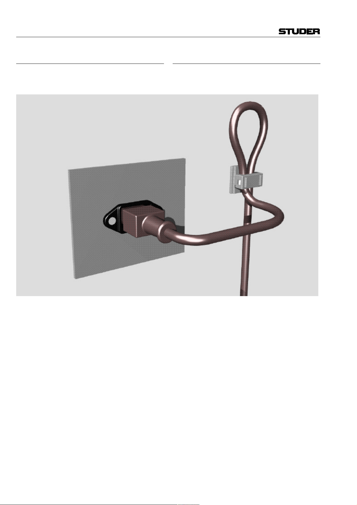
Zugentlastung für den Netzanschluss
Zum Verankern von Steckverbindungen ohne mechanische Verriegelung (z.B. IEC-Kaltgerätedosen) empfehlen wir die folgende Anordnung:
Mains connector strain relief
For anchoring connectors without a mechanical lock
(e.g. IEC mains connectors), we recommend the following arrangement:
Vorgehen: Der mitgelieferte Kabelhalter ist selbstklebend. Bitte beachten Sie bei der Montage die folgenden
Regeln:
1. Der Untergrund muss sauber, trocken und frei von
Fett, Öl und anderen Verunreinigungen sein. Temperaturbereich für optimale Verklebung: 20...40° C.
2. Entfernen Sie die Schutzfolie auf der Rückseite des
Kabelhalters und bringen sie ihn mit kräftigem
Druck an der gewünschten Stelle an. Lassen sie ihn
unbelastet so lange wie möglich ruhen – die maximale Klebekraft ist erst nach rund 24 Stunden erreicht.
3. Die Stabilität des Kabelhalters wird erhöht, wenn
Sie ihn zusätzlich verschrauben. Zu diesem Zweck
liegen ihm eine selbstschneidende Schraube sowie
eine M4-Schraube mit Mutter bei.
4. Legen Sie das Kabel gemäss Figur in den Halter ein
und pressen Sie die Klemme kräftig auf, bis das Kabel fixiert ist.
Procedure: The cable clamp shipped with your unit is
auto-adhesive. If mounting, please follow the rules below:
1. The surface to be adhered to must be clean, dry, and
free from grease, oil or other contaminants. Best application temperature range is 20...40° C.
2. Remove the plastic protective backing from the rear
side of the clamp and apply it firmly to the surface
at the desired position. Allow as much time as possible for curing. The bond continues to develop for
as long as 24 hours.
3. For improved stability, the clamp can be fixed with
a screw. For this purpose, a self-tapping screw and
an M4 bolt and nut are included.
4. Place the cable into the clamp as shown in the illus-
tration above and firmly press down the internal top
cover until the cable is fixed.
IV
Page 7

UMGEBUNGSBEDINGUNGEN / AMBIENT CONDITIONS
Lufttemperatur und Feuchtigkeit
Allgemein
Die Betriebstauglichkeit des Gerätes oder Systems ist unter
folgenden Umgebungsbedingungen gewährleistet:
EN 60721-3-3, Set IE32, Wert 3K3.
Diese Norm umfasst einen umfassenden Katalog von Parametern; die wichtigsten davon sind: Umgebungstemperatur
+5...+40 °C; rel. Luftfeuchtigkeit 5...85% – d.h. weder Kondensation noch Eisbildung; abs. Luftfeuchtigkeit 1...25 g/m³; Tem-
peratur-Änderungsrate < 0,5 °C/min. In den folgenden Abschnitten wird darauf näher eingegangen.
Unter den genannten Bedingungen startet und arbeitet das
Gerät oder System problemlos. Ausserhalb dieser Spezifikationen möglicherweise auftretende Probleme sind in den folgenden
Abschnitten beschrieben.
Umgebungstemperatur
Geräte und Systeme von Studer sind allgemein für einen Umgebungstemperaturbereich (d.h. Temperatur der eintretenden
Kühlluft) von +5...+40 °C ausgelegt. Bei Installation in einem
Schrank muss der vorgesehene Luftdurchsatz und dadurch die
Konvektionskühlung gewährleistet sein. Folgende Tatsachen
sind dabei zu berücksichtigen:
1. Die zulässige Umgebungstemperatur für den Betrieb der
Halbleiter-Bauelemente beträgt 0 °C bis +70 °C (commercial
temperature range for operation).
2. Der Luftdurchsatz der Anlage muss gewährleisten, dass die
austretende Kühlluft ständig kühler ist als 70 °C.
3. Die mittlere Erwärmung der Kühlluft soll 20 K betragen,
die maximale Erwärmung an den heissen Komponenten darf
somit um weitere 10 K höher liegen.
4. Zum Abführen einer Verlustleistung von 1 kW bei dieser
zulässigen mittleren Erwärmung ist eine Luftmenge von
2,65 m³/min notwendig.
Beispiel: Für ein Rack mit einer Leistungsaufnahme P = 800 W
ist eine Kühlluftmenge von 0,8 * 2,65 m³/min nötig, entsprechend 2,12 m³/min.
5. Soll die Kühlfunktion der Anlage (z.B. auch bei LüfterAusfall oder Bestrahlung durch Spotlampen) überwacht werden, so ist die Temperatur der Abluft unmittelbar oberhalb der
Einschübe an mehreren Stellen im Rack zu messen; die Ansprechtemperatur der Sensoren soll 65 bis 70 °C betragen.
Air temperature and humidity
General
Normal operation of the unit or system is warranted under the
following ambient conditions defined by:
EN 60721-3-3, set IE32, value 3K3.
This standard consists of an extensive catalogue of parameters,
the most important of which are: ambient temperature +5...
+40° C, relative humidity 5...85% – i.e. no formation of condensation or ice; absolute humidity 1...25 g/m³; rate of temperature change < 0,5 °C/min. These parameters are dealt with
in the following paragraphs.
Under these conditions the unit or system starts and works
without any problem. Beyond these specifications, possible
problems are described in the following sections.
Ambient temperature
Units and systems by Studer are generally designed for an ambient temperature range (i.e. temperature of the incoming air) of
+5...+40 °C. When rack mounting the units, the intended air
flow and herewith adequate cooling must be provided. The
following facts must be considered:
1. The admissible ambient temperature range for operation of
the semiconductor components is 0 °C to +70 °C (commercial
temperature range for operation).
2. The air flow through the installation must provide that the
outgoing air is always cooler than 70 °C.
3. Average heat increase of the cooling air shall be 20 K, allowing for an additional maximum 10 K increase at the hot
components.
4. In order to dissipate 1 kW with this admissible average heat
increase, an air flow of 2,65 m³/min is required.
Example: A rack dissipating P = 800 W requires an air flow of
0,8 * 2,65 m³/min which corresponds to 2,12 m³/min.
5. If the cooling function of the installation must be monitored
(e.g. for fan failure or illumination with spot lamps), the outgoing air temperature must be measured directly above the modules at several places within the rack. The trigger temperature of
the sensors should be 65 to 70 °C.
Reif und Tau
Das unversiegelte System (Steckerpartien, Halbleiteranschlüsse) verträgt zwar leichte Eisbildung (Reif). Mit blossem Auge
sichtbare Betauung führt jedoch bereits zu Funktionsstörungen.
In der Praxis kann mit einem zuverlässigen Betrieb der Geräte
bereits im Temperaturbereich ab –15 °C gerechnet werden,
wenn für die Inbetriebnahme des kalten Systems die folgende
allgemeine Regel beachtet wird:
Wird die Luft im System abgekühlt, so steigt ihre relative
Feuchtigkeit an. Erreicht diese 100%, kommt es zu Niederschlag, meist in der Grenzschicht zwischen der Luft und einer
kühleren Oberfläche, und somit zur Bildung von Eis oder Tau
an empfindlichen Systemstellen (Kontakte, IC-Anschlüsse etc.).
Ein störungsfreier Betrieb mit interner Betauung, unabhängig
von der Temperatur, ist nicht gewährleistet.
Frost and dew
The unsealed system parts (connector areas and semiconductor
pins) allow for a minute formation of ice or frost. However,
formation of dew visible with the naked eye will already lead to
malfunctions. In practice, reliable operation can be expected in
a temperature range above –15 °C, if the following general rule
is considered for putting the cold system into operation:
If the air within the system is cooled down, the relative humidity rises. If it reaches 100%, condensation will arise, usually in
the boundary layer between the air and a cooler surface, together with formation of ice or dew at sensitive areas of the
system (contacts, IC pins, etc.). Once internal condensation
occurs, troublefree operation cannot be guaranteed, independent
of temperature.
V
Page 8
UMGEBUNGSBEDINGUNGEN / AMBIENT CONDITIONS
Vor der Inbetriebnahme muss das System auf allfällige interne
Betauung oder Eisbildung überprüft werden. Nur bei sehr
leichter Eisbildung kann mit direkter Verdunstung (Sublimation) gerechnet werden; andernfalls muss das System im abgeschalteten Zustand gewärmt und getrocknet werden.
Das System ohne feststellbare interne Eisbildung oder Betauung soll möglichst homogen (und somit langsam) mit eigener
Wärmeleistung aufgewärmt werden; die Lufttemperatur der
Umgebung soll ständig etwas tiefer als diejenige der Systemabluft sein.
Ist es unumgänglich, das abgekühlte System sofort in warmer
Umgebungsluft zu betreiben, so muss diese entfeuchtet sein.
Die absolute Luftfeuchtigkeit muss dabei so tief sein, dass die
relative Feuchtigkeit, bezogen auf die kälteste Oberfläche im
System, immer unterhalb 100% bleibt.
Es ist dafür zu sorgen, dass beim Abschalten des Systems die
eingeschlossene Luft möglichst trocken ist (d.h. vor dem Abschalten im Winter den Raum mit kalter, trockener Luft belüften und feuchte Gegenstände, z.B. Kleider, entfernen).
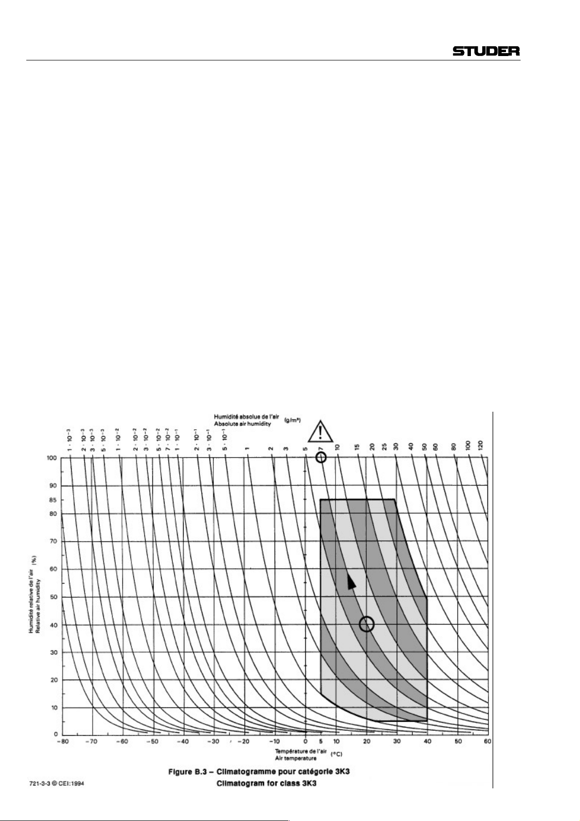
Die Zusammenhänge sind im folgenden Klimatogramm ersichtlich. Zum kontrollierten Verfahren gehören Thermometer
und Hygrometer sowie ein Thermometer innerhalb des Systems.
Beispiel 1: Ein Ü-Wagen mit einer Innentemperatur von 20 °C
und 40% relativer Luftfeuchtigkeit wird am Abend abgeschaltet. Sinkt die Temperatur unter +5 °C, bildet sich Tau oder Eis.
Beispiel 2: Ein Ü-Wagen wird morgens mit 20 °C warmer Luft
von 40% relativer Luftfeuchtigkeit aufgewärmt. Auf Teilen, die
kälter als +5 °C sind, bildet sich Tau oder Eis.
Before putting into operation, the system must be checked for
internal formation of condensation or ice. Only with a minute
formation of ice, direct evaporation (sublimation) may be expected; otherwise the system must be heated and dried while
switched off.
A system without visible internal formation of ice or condensation should be heated up with its own heat dissipation, as homogeneously (and subsequently as slow) as possible; the ambient temperature should then always be lower than the outgoing
air.
If it is absolutely necessary to operate the system immediately
within warm ambient air, this air must be dehydrated. In such a
case, the absolute humidity must be so low that the relative
humidity, related to the coldest system surface, always remains
below 100%.
Ensure that the enclosed air is as dry as possible when powering off (i.e. before switching off in winter, aerate the room with
cold, dry air, and remove humid objects as clothes from the
room).
These relationships are visible from the following climatogram.
For a controlled procedure, thermometer and hygrometer as well
as a thermometer within the system will be required.
Example 1: An OB-van having an internal temperature of
20 °C and rel. humidity of 40% is switched off in the evening.
If temperature falls below +5 °C, dew or ice will be forming.
Example 2: An OB-van is heated up in the morning with air of
20 °C and a rel. humidity of 40%. On all parts being cooler than
+5 °C, dew or ice will be forming.
VI
Page 9

WARTUNG / MAINTENANCE
Wartung und Reparatur
Durch Entfernen von Gehäuseteilen, Abschirmungen
etc. werden stromführende Teile freigelegt. Deshalb
müssen u.a. die folgenden Grundsätze beachtet werden:
Eingriffe in das Gerät dürfen nur von Fachpersonal
unter Einhaltung der geltenden Vorschriften vorgenommen werden.
Vor Entfernen von Gehäuseteilen muss das Gerät ausgeschaltet und vom Netz getrennt werden.
Bei geöffnetem, vom Netz getrenntem Gerät dürfen
Teile mit gefährlichen Ladungen (z. B. Kondensatoren,
Bildröhren) erst nach kontrollierter Entladung, heiße
Bauteile (Leistungshalbleiter, Kühlkörper etc.) erst
nach deren Abkühlen berührt werden.
Bei Wartungsarbeiten am geöffneten, unter Netzspannung stehenden Gerät dürfen blanke Schaltungsteile und metallene Halbleitergehäuse weder direkt noch
mit nichtisoliertem Werkzeug berührt werden.
Zusätzliche Gefahren bestehen bei unsachgemässer
Handhabung besonderer Komponenten:
• Explosionsgefahr bei Lithiumzellen, Elektrolyt-Kondensatoren und Leistungshalbleitern
• Implosionsgefahr bei evakuierten Anzeigeeinheiten
• Strahlungsgefahr bei Lasereinheiten (nichtionisierend), Bildröhren (ionisierend)
• Verätzungsgefahr bei Anzeigeeinheiten (LCD) und
Komponenten mit flüssigem Elektrolyt.
Solche Komponenten dürfen nur von ausgebildetem
Fachpersonal mit den vorgeschriebenen Schutzmitteln
(u.a. Schutzbrille, Handschuhe) gehandhabt werden.
Maintenance and Repair
The removal of housing parts, shields, etc. exposes
energized parts. For this reason the following precautions should be observed:
Maintenance should only be performed by trained personnel in accordance with the applicable regulations.
The equipment should be switched off and disconnected
from the AC power outlet before any housing parts are
removed.
Even if the equipment is disconnected from the power,
parts with hazardous charges (e.g. capacitors, picture
tubes) must not be touched until they have been properly discharged. Touch hot components (power semiconductors, heat sinks, etc.) only when cooled off.
If maintenance is performed on a unit that is opened
and switched on, no uninsulated circuit components and
metallic semiconductor housings must be touched neither with your bare hands nor with uninsulated tools.
Certain components pose additional hazards:
• Explosion hazard from lithium batteries, electrolytic
capacitors and power semiconductors
• Implosion hazard from evacuated display units
• Radiation hazard from laser units (non-ionizing),
picture tubes (ionizing)
• Caustic effect of display units (LCD) and such components containig liquid electrolyte.
Such components should only be handled by trained
personnel who are properly protected (e.g. safety
goggles, gloves).
VII
Page 10

WARTUNG / MAINTENANCE
Elektrostatische Entladung (ESD)
bei Wartung und Reparatur
ATTENTION:
ATTENTION:
ACHTUNG:
Viele ICs und andere Halbleiter sind empfindlich gegen
elektrostatische Entladung (ESD). Unfachgerechte Behandlung von Baugruppen mit solchen Komponenten
bei Wartung und Reparatur kann deren Lebensdauer
drastisch vermindern.
Bei der Handhabung der ESD-empfindlichen Komponenten sind u.a. folgende Regeln zu beachten:
Electrostatic Discharge (ESD)
during Maintenance and Repair
Observe precautions for handling devices sensitive to
electrostatic discharge!
Respecter les précautions d’usage concernant la manipulation de composants sensibles à l’électricité statique!
Vorsichtsmassnahmen bei Handhabung elektrostatisch
entladungsgefährdeter Bauelemente beachten!
Many ICs and semiconductors are sensitive to electrostatic discharge (ESD). The life of components containing such elements can be drastically reduced by
improper handling during maintenance and repair work.
Please observe the following rules when handling ESD
sensitive components:
• ESD-empfindliche Komponenten dürfen ausschliesslich in dafür bestimmten und bezeichneten Verpackungen gelagert und transportiert werden.
• Unverpackte, ESD-empfindliche Komponenten dürfen nur in dafür eingerichteten Schutzzonen (EPA,
z.B. Gebiet für Feldservice, Reparatur- oder Serviceplatz) gehandhabt und nur von Personen berührt
werden, die durch ein Handgelenkband mit Seriewiderstand mit dem Massepotential des Reparaturoder Serviceplatzes verbunden sind. Das gewartete
Gerät wie auch Werkzeug, Hilfsmittel, EPAtaugliche (elektrisch halbleitende) Arbeits-, Ablageund Bodenmatten müssen ebenfalls mit diesem Potential verbunden sein.
• Die Anschlüsse der ESD-empfindlichen Komponenten dürfen unkontrolliert weder mit elektrostatisch
aufladbaren (Gefahr von Spannungsdurchschlag),
noch mit metallischen Oberflächen (Schockentladungsgefahr) in Berührung kommen.
• Um undefinierte transiente Beanspruchung der Komponenten und deren eventuelle Beschädigung durch
unerlaubte Spannung oder Ausgleichsströme zu vermeiden, dürfen elektrische Verbindungen nur am abgeschalteten Gerät und nach dem Abbau allfälliger
Kondensatorladungen hergestellt oder getrennt werden.
• ESD sensitive components should only be stored and
transported in the packing material specifically provided for this purpose.
• Unpacked ESD sensitive components should only be
handled in ESD protected areas (EPA, e.g. area for
field service, repair or service bench) and only be
touched by persons who wear a wristlet that is connected to the ground potential of the repair or service
bench by a series resistor. The equipment to be repaired or serviced and all tools, aids, as well as electrically semiconducting work, storage and floor mats
should also be connected to this ground potential.
• The terminals of ESD sensitive components must not
come in uncontrolled contact with electrostatically
chargeable (voltage puncture) or metallic surfaces
(discharge shock hazard).
• To prevent undefined transient stress of the components and possible damage due to inadmissible voltages or compensation currents, electrical connections
should only be established or separated when the
equipment is switched off and after any capacitor
charges have decayed.
VIII
Page 11
WARTUNG / MAINTENANCE
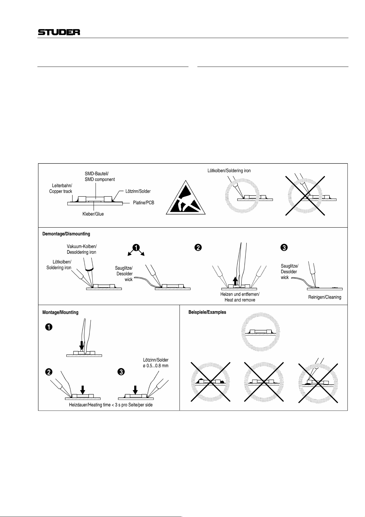
SMD-Bauelemente
Der Austausch von SMD-Bauelementen ist ausschliesslich geübten Fachleuten vorbehalten. Für verwüstete
Platinen können keine Ersatzansprüche geltend gemacht
werden. Beispiele für korrekte und falsche SMDLötverbindungen in der Abbildung weiter unten.
Bei Studer werden keine handelsüblichen SMD-Teile
bewirtschaftet. Für Reparaturen sind die notwendigen
Bauteile lokal zu beschaffen. Die Spezifikationen von
Spezialbauteilen finden Sie in der Serviceanleitung.
SMD Components
SMDs should only be replaced by skilled specialists.
No warranty claims will be accepted for circuit boards
that have been ruined. Proper and improper SMD soldering joints are depicted below.
Studer does not keep any commercially available SMDs
in stock. For repair the corresponding devices should be
purchased locally. The specifications of special components can be found in the service manual.
IX
Page 12

EMV / EMC
Störstrahlung und Störfestigkeit
Das Gerät entspricht den Schutzanforderungen auf dem
Gebiet elektromagnetischer Phänomene, wie u.a. in den
Richtlinien 89/336/EWG und FCC, Part 15, aufgeführt:
1. Vom Gerät erzeugte elektromagnetische Strahlung ist
soweit begrenzt, dass bestimmungsgemässer Betrieb
anderer Geräte und Systeme möglich ist.
2. Das Gerät weist eine angemessene Festigkeit gegen
elektromagnetische Störungen auf, so dass sein bestimmungsgemässer Betrieb möglich ist.
Das Gerät wurde getestet und erfüllt die Bedingungen
der im Kapitel „Technische Daten“ aufgeführten EMVStandards. Die Limiten dieser Standards gewährleisten
mit angemessener Wahrscheinlichkeit sowohl den
Schutz der Umgebung wie auch entsprechende Störfestigkeit des Gerätes. Absolute Garantie, dass keine
unerlaubte elektromagnetische Beeinträchtigung während des Betriebes entsteht, ist jedoch nicht gegeben.
Um die Wahrscheinlichkeit solcher Beeinträchtigung
weitgehend auszuschliessen, sind u.a. folgende Massnahmen zu beachten:
• Installieren Sie das Gerät gemäss den Angaben in der
Betriebsanleitung, und verwenden Sie das mitgelieferte Zubehör.
• Verwenden Sie im System und in der Umgebung, in
denen das Gerät eingesetzt ist, nur Komponenten
(Anlagen, Geräte), die ihrerseits die Anforderungen
der obenerwähnten Standards erfüllen.
• Sehen Sie ein Erdungskonzept des Systems vor, das
sowohl die Sicherheitsanforderungen (die Erdung der
Geräte gemäss Schutzklasse I mit einem Schutzleiter
muss gewährleistet sein), wie auch die EMV-Belange
berücksichtigt. Bei der Entscheidung zwischen sternoder flächenförmiger bzw. kombinierter Erdung sind
Vor- und Nachteile gegeneinander abzuwägen.
• Benutzen Sie abgeschirmte Kabel, wo vorgesehen.
Achten Sie auf einwandfreie, grossflächige, korrosionsbeständige Verbindung der Abschirmung zum
entsprechenden Steckeranschluss und dessen Gehäuse. Beachten Sie, dass eine nur an einem Ende angeschlossene Kabelabschirmung als Sende- bzw. Empfangsantenne wirken kann (z.B. bei wirksamer Kabellänge von 5 m oberhalb von 10 MHz), und dass
die Flanken digitaler Kommunikationssignale hochfrequente Aussendungen verursachen (z.B. LS- oder
HC-Logik bis 30 MHz).
• Vermeiden Sie Bildung von Masseschleifen oder vermindern Sie deren unerwünschte Auswirkung, indem
Sie deren Fläche möglichst klein halten und den darin
fliessenden Strom durch Einfügen einer Impedanz
(z.B. Gleichtaktdrossel) reduzieren.
Electromagnetic Compatibility
The equipment conforms to the protection requirements
relevant to electromagnetic phenomena that are listed in
the guidelines 89/336/EC and FCC, part 15.
1. The electromagnetic interference generated by the
equipment is limited in such a way that other equipment and systems can be operated normally.
2. The equipment is adequately protected against electromagnetic interference so that it can operate correctly.
The unit has been tested and conforms to the EMC
standards applicable to residential, commercial and
light industry, as listed in the section „Technical Data“.
The limits of these standards reasonably ensure protection of the environment and corresponding noise immunity of the equipment. However, it is not absolutely
warranted that the equipment will not be adversely affected by electromagnetic interference during operation.
To minimize the probability of electromagnetic interference as far as possible, the following recommendations
should be followed:
• Install the equipment in accordance with the operating instructions. Use the supplied accessories.
• In the system and in the vicinity where the equipment
is installed, use only components (systems, equipment) that also fulfill the above EMC standards.
• Use a system grounding concept that satisfies the
safety requirements (protection class I equipment
must be connected with a protective ground conductor) that also takes into consideration the EMC requirements. When deciding between radial, surface or
combined grounding, the advantages and disadvantages should be carefully evaluated in each case.
• Use shielded cables where shielding is specified. The
connection of the shield to the corresponding connector terminal or housing should have a large surface and be corrosion-proof. Please note that a cable
shield connected only single-ended can act as a
transmitting or receiving antenna (e.g. with an effective cable length of 5 m, the frequency is above
10 MHz) and that the edges of the digital communication signals cause high-frequency radiation (e.g.
LS or HC logic up to 30 MHz).
• Avoid ground loops or reduce their adverse effects
by keeping the loop surface as small as possible, and
reduce the noise current flowing through the loop by
inserting an additional impedance (e.g. commonmode rejection choke).
X
Page 13

Class A Equipment - FCC Notice
Konformitätserklärungen / Declarations of conformity
This equipment has been tested and found to comply with
the limits for a Class A digital device, pursuant to Part 15
of the FCC Rules. These limits are designed to provide a
reasonable protection against harmful interference when the
equipment is operated in a commercial environment. This
equipment generates, uses, and can radiate radio frequency
energy and, if not installed and used in accordance with the
instruction manual, may cause harmful interference to radio
communications. Operation of this equipment in a residen-
CE-Konformitätserklärung
Der Hersteller,
Studer Professional Audio AG,
CH-8105 Regensdorf,
erklärt in eigener Verantwortung, dass das Produkt
tial area is likely to cause harmful interference in which
case the user will be required to correct the interference at
his own expense.
Caution:
Any changes or modifications not expressly approved by
the manufacturer could void the user's authority to operate
the equipment. Also refer to relevant information in this
manual.
CE Declaration of Conformity
The manufacturer,
Studer Professional Audio AG,
CH-8105 Regensdorf,
declares under his sole responsibility that the product
Studer D19 MicVALVE, Valve Dignified Mic/Line Pre-
amplifier, (ab Serie-Nr. 101),
auf das sich diese Erklärung bezieht, entsprechend den
Bestimmungen der EU-Richtlinien und Ergänzungen
• Elektromagnetische Verträglichkeit (EMV):
89/336/EWG + 92/31/EWG + 93/68/EWG
• Niederspannung:
73/23/EWG + 93/68/EWG
mit den folgenden Normen und normativen Dokumenten
übereinstimmt:
• Sicherheit:
Schutzklasse 1, EN 60950:1992 + A1/A2:1993
• EMV:
EN 50081-1:1992, EN 50082:1992.
Regensdorf, 6. Februar 1996
B. Hochstrasser, Geschäftsleiter
Studer D19 MicVALVE, Valve Dignified Mic/Line Pre-
amplifier, (on from serial No. 101),
to which this declaration relates, according to following
regulations of EU directives and amendments
• Electromagnetic Compatibility (EMC):
89/336/EEC + 92/31/EEC + 93/68/EEC
• Low Voltage (LVD):
73/23/EEC + 93/68/EEC
is in conformity with the following standards or other normative documents:
• Safety:
Class 1, EN 60950:1992 + A1/A2:1993
• EMC:
EN 50081-1:1992, EN 50082:1992.
Regensdorf, February 6, 1996
B. Hochstrasser, Managing director
P. Fiala, Leiter QS
P. Fiala, Manager QA
XI
Page 14

D19 MicVALVE
CONTENTS
1 Come in!.................................................................................................................................................................E1/1
1.1 Basic Information ............................................................................................................................................E1/1
1.2 General............................................................................................................................................................E1/2
1.2.1 Scope of Delivery.....................................................................................................................................E1/2
1.2.2 Options....................................................................................................................................................E1/2
1.2.3 Accessories ..............................................................................................................................................E1/2
1.3 Safety and Connections....................................................................................................................................E1/3
1.3.1 Utilization for the Purpose Intended .........................................................................................................E1/3
1.3.2 Power Connection ....................................................................................................................................E1/3
Connector Panel ..................................................................................................................................................E1/4
1.4 Technical Specifications.................................................................................................................................. E1/6
1.4.1 Audio Specifications ................................................................................................................................E1/6
1.4.2 Synchronization .......................................................................................................................................E1/7
1.4.3 Power Supply...........................................................................................................................................E1/7
1.4.4 Primary Fuse............................................................................................................................................ E1/8
1.4.5 Operating Conditions...............................................................................................................................E1/8
1.4.6 Safety and EMC Standards....................................................................................................................... E1/8
1.4.7 Mechanical Data...................................................................................................................................... E1/8
2 Operation...............................................................................................................................................................E2/1
2.1 Operating Elements.........................................................................................................................................E2/1
2.2 Audio and Sync Connections, Pin Assignments...............................................................................................E2/4
2.2.1 Mic and Line Inputs, Insert Returns.........................................................................................................E2/4
2.2.2 Line Outputs, Insert Sends.......................................................................................................................E2/4
2.2.3 AES/EBU, Digital Output........................................................................................................................E2/4
2.2.4 AES IN, External AES/EBU Synchronization..........................................................................................E2/4
2.2.5 Word Clock In/Out ..................................................................................................................................E2/4
2.2.6 Using the TDIF-1 8-Channel Interface.....................................................................................................E2/5
2.2.7 Using the Optical ADAT 8-Channel Interface.......................................................................................... E2/6
2.3 Application Ideas and Examples......................................................................................................................E2/7
2.3.1 Wiring for External Synchronization ....................................................................................................... E2/9
3 Additional information..........................................................................................................................................E3/1
3.1 What the Heck is Noise Shaping? ....................................................................................................................E3/1
3.2 Block Diagrams............................................................................................................................................... E3/3
3.2.1 Global Audio Block Diagram ...................................................................................................................E3/3
3.2.2 Synchronization Block Diagram............................................................................................................... E3/3
Date printed: 9.2.2000 Contents E0/1
Page 15

1 COME IN!
1.1 Basic Information
D19 MicVALVE
We are happy to welcome you in the steadily growing circle of the Studer
D19 MicVALVE's users, and we felicitate you on your selection. Thanks to
Studer's experience collected during more than 40 years of business in the
professional audio products field, you may expect that the performance of
your new unit will fulfill your highest demands.
Together with the renaissance of natural sounds and the classical recorded
performance of real artists (as opposed to computer-gernerated sounds), users frequently quote the term “valve sound” in a meaning far beyound nostalgic reminiscence. Studer engineers have systematically investigated the
differences between valve and transistor amplifiers. The result of this research is now part of the D19 MicVALVE, where the typical properties of
valve amplifiers are implemented in the form of adjustable parameters.
The MicVALVE is a two-channel preamplifier for microphone and line level
signals with analog and digital outputs. The main signal path is designed in
semiconductor technology and allows top quality “direct-to-digital” recordings. A Valve Dignifier stage equipped with 2 × ECC 81 valves per channel
can be switched into the signal path, providing a number of front panel controls for individual valve sound treatment. Each input has a switchable analog insert and an analog output. Both channels are then combined to an
AES/EBU digital output. The built-in 20 bit A/D converter technology represents today's state of the art. Thanks to the modular concept the A/D converter can easily be upgraded as technology advances. A TDIF or an optical
ADAT interface can be installed as an option.
Even in connection with recording media having only the reduced 16 bit
resolution, the Studer MicVALVE leads to improved results thanks to DSP
dithering and noise shaping technology which is used instead of simple truncating.
Date printed: 9.2.2000 Come in! E1/1
Page 16

D19 MicVALVE
1.2 General
1.2.1 Scope of Delivery
The D19 MicVALVE (order No. 66.655.000.00) is supplied with an IEC
320/C13 socket, a hex-socket-screwdriver (2.5 mm), and this manual.
1.2.2 Options Order No.
Digital Audio Output Options:
ADAT Interface: 8-channel optical digital audio output card 1.650.050.20
for connecting with the ADAT and compatible
8-channel recorders or other equipment featuring
the ADAT standard connectors.
TDIF-1 Interface: 8-channel digital audio output card 1.650.052.20
for connecting with the DA-88 and compatible
8-channel recorders or other equipment featuring
the TDIF-1 standard connectors.
Note: These two options are identical to the ones used for the eight-channel D19
MicAD preamp; the channel routing, however, can be selected individually
on the D19 MicVALVE.
Super ADC: Converter assembly for further improving 1.655.042.00
the A/D performance
1.2.3 Accessories Order No.
Accessories/Spares: Kit, consisting of: 20.020.302.51
• Mating XLR connectors (7 pcs. male,
5 pcs. female)
• Rotary knobs (2 × small, 1 × large)
• Rack mounting screws with washers
(4 pcs. each)
Interface cables: ADAT/Alesis optical interface cable, 10.325.010.00
length 1.0 m
ADAT/Alesis optical interface cable, 10.325.011.00
length 5.0 m
TDIF-1/Tascam interface cable F-10.025.031.08
“PW 88D”, length 1.0 m
TDIF-1/Tascam interface cable F-10.025.031.09
“PW 88D”, length 5.0 m
E1/2 Come in! Date printed: 9.2.2000
Page 17
1.3 Safety and Connections
1.3.1 Utilization for the Purpose Intended
The Studer D19 MicVALVE 2-channel Mic/Line valve preamplifier is designed for professional use. It is presumed that the unit is operated only by
trained personnel; servicing must be performed by qualified experts.
The electrical connections may be connected only to the appropriate voltages and signals specified in this manual. Please consult the Security and
EMC section at the very beginning of this manual.
1.3.2 Power Connection
There is no need to select a specific mains voltage setting because the Studer
D19 MicVALVE can be operated on mains voltages from 100 through
240 VAC, 50...60 Hz.
D19 MicVALVE
Danger: Repair work may only be performed by a trained service technician. The
primary fuse of the D19 MicVALVE must be replaced by a spare fuse of
exactly the same type. The D19 MicVALVE must not be opened by the user
– the risk of a severe electric shock hazard is increased as a result of the
high operating voltage of the vacuum tubes (300 V)!
Power cable: The supplied power socket has to be fitted with a mating power cable incl.
plug by an electrician, if your local Studer agency or your dealer should not
have added a fitting power cable.
☛ Please consult the Safety section at the very beginning of this manual.
Date printed: 9.2.2000 Come in! E1/3
Page 18

D19 MicVALVE
1.3.3 Connector Panel
DIGITAL MCH OUT
[9]
INSERT SENDS INSERT RETURNS
m m
f
MIC INPUTS SYNCHRONIZATION DIGITAL OUT
RL
LRL AES/EBU
R
[2]
LINE OUTPUTSLINE INPUTS
[10]
L
m m
L
[4]
ff
R
fffff
R
WCLK OUTWCLK INAES IN
[5] [6] [7] [8] [1][3]
[1] AC POWER Connector for socket IEC 320/C13.
Supply voltage range 100...240 V
(without voltage selector); mains fre-
AC
quency 50...60 Hz.
For connecting to the mains, please consult the Safety section at the very
beginning of this manual.
OPTICAL OUT
DIGITAL MCH OUT
TDIF-1
m
[11]
[2] MIC INPUTS Microphone inputs on female XLR connectors. Sensitivity for full-scale
input level of the A/D converter adjustable from –55 dBu to +20 dBu. Input
impedance 1 kΩ, transformer-balanced.
[3] LINE INPUTS Analog line inputs on female XLR connectors. Sensitivity for full-scale
input level of the A/D converter adjustable from –1 dBu to +24 dBu. Input
impedance 11 kΩ, transformer-balanced.
[4] LINE OUTPUTS Analog line outputs on male XLR connectors. Output impedance ≤ 20 Ω,
electronically balanced.
[5] AES IN Input for external synchronization via AES/EBU (female XLR connector).
[6] WCLK IN Input for external Word Clock synchronization (BNC connector, 75 Ω).
[7] WCLK OUT Output of the Word Clock Sync signal (BNC connector, 75 Ω).
[8] DIGITAL OUT AES/EBU output on male XLR connector, transformer-balanced. Output
impedance 110 Ω.
[9] INSERT SENDS Output of the insert point, on male XLR connectors. Output impedance
~50 Ω, electronically balanced.
E1/4 Come in! Date printed: 9.2.2000
Page 19

D19 MicVALVE
[10] INSERT RETURNS Input of the insert point, on female XLR connectors, for external units. The
insert points can be switched between input and output of the valve stage.
Input impedance 11 kΩ, electronically balanced.
[11] Optional Digital Outputs TDIF-1 eight-channel format or optical ADAT eight-channel format.
Date printed: 9.2.2000 Come in! E1/5
Page 20

D19 MicVALVE
1.4 Technical Specifications (Subject to Change without Notice)
A/D converter: Delta-Sigma, 64 × oversampling, resolution 20 bit, linear (modular).
Analog inputs: 2 separate Mic and Line inputs on XLRs, transformer-balanced and float-
ing.
2 stepped attenuators and 2 potentiometers for MIC/LINE Gain setting.
Functions selectable per channel: Phase, Phantom (Mic input only), Highpass filter (–3 dB @ 75 Hz, 12 dB/oct.; Mic input only).
2 switchable Insert Return inputs (XLR), electronically balanced; input level
fixed.
Analog outputs: 2 Line outputs (XLR), electronically balanced. Output level adjustable.
2 separate Insert Send outputs (XLR), electronically balanced; output level
fixed.
Metering: PPM, peak program meter with switchable Peak Hold function;
16-segment bargraph displays, range –60 dBFS...Overload.
Digital audio processing: DC reject (always on)
Output word length 20 bit, 16 bit with Dithering or 16 bit with Noise
Shaping.
1.4.1 Audio Specifications
Conditions: all measurements without valve stage, at fs = 48 kHz
Insert OFF, unless otherwise noted
20 Hz...20 kHz, unless otherwise noted.
Analog – Digital:
Line inputs: Conditions: Gain = 24 dBu
Frequency response: ±0.1 dB
Signal/noise ratio: > 106 dBFS, CCIR 468-3
THD + Noise: < –80 dBFS, @ –1 dB
< –104 dBFS, @ –30 dB
< –103 dBFS, @ –30 dBFS, looped via Insert
CMRR: > 50 dB
Crosstalk: < –100 dB @ 15 kHz, Fine Gain min.
Sensitivity: –1...+24 dBu for Full Scale
Microphone inputs: Conditions: Gain = 20 dBu
Frequency response: ±0.4 dB
Noise figure: < 3.5 typ. @ max. gain, 20 Hz...20 kHz, 24°C
CMRR: > 60 dB
Crosstalk: < –100 dB @ 15 kHz, Fine Gain min., Gain = 20 dBu
Sensitivity: –55...+20 dBu for Full Scale
, without Super ADC option
FS
FS
FS
FS
FS
E1/6 Come in! Date printed: 9.2.2000
Page 21

D19 MicVALVE
Digital output: AES/EBU output on XLR, transformer-balanced and floating according to
AES3-1992, ANSI S4.40-1992
Amplitude: 2...5 V
Impedance: 110 Ω
Optional digital outputs: ADAT, optical 8-channel format.
TDIF-1, 8-channel, 20 or 16 bit serial audio data with sampling rate information; C-MOS level.
Analog – Analog:
Line In – Line Out: Conditions: Input gain = 24 dBu
Frequency response: ±0.15 dB
Signal/noise ratio: > 118 dBFS, CCIR 468-3
THD + Noise: < –80 dBFS, @ –1 dB
FS
< –112 dBFS, @ –30 dBFS, Output Gain 24 dBu
< –103 dBFS, @ –30 dBFS, Output Gain 4 dBu
Crosstalk: < –100 dB, @ 15 kHz, Output Gain 24 dBu
Phase error: < ±1°
Insert:
Max. output level SEND: 17.2 dBu
Max. input level RETURN: 17.2 dBu
FS
FS
Impedances:
Microphone input: 1 kΩ
Line input: 11 kΩ
Insert Return: 11 kΩ
Line output: < 20 Ω
Insert Send: 50 Ω
FS
FS
FS
FS
1.4.2 Synchronization
Word Clock IN 30...54 kHz, TTL level, impedance 75 Ω
Word Clock OUT 30...54 kHz, TTL level, impedance 75 Ω
AES/EBU IN 30...54 kHz, transformer-balanced and floating, impedance 110 Ω, accord-
ing to AES 11-1991
Internal clock 44.1 kHz / 48 kHz
1.4.3 Power Supply
Mains voltage: 100...240 VAC, 50...60 Hz
Current consumption: 1...0.5 A
Appliance inlet: IEC 320/C14
Date printed: 9.2.2000 Come in! E1/7
Page 22

D19 MicVALVE
1.4.4 Primary Fuse
Danger: The primary fuse is located inside the D19 MicVALVE. Repair work may
only be performed by a trained service technician. The primary fuse must be
replaced by a spare fuse of exactly the same type and value. The unit must
not be opened by the user – the risk of a severe electric shock hazard is increased as a result of the high operating voltage of the vacuum tubes
(300 V)!
Spare fuse: T 2.0 A H 250 V UL, CSA (5 × 20 mm) Order No. 51.01.1022
1.4.5 Operating Conditions
Ambient air temperature: +10°...+40°C
Relative humidity: Category F (DIN 40040)
1.4.6 Safety and EMC Standards
Safety: Protection class I according to EN 60950; 1992 + A1/A2; 1993 (UL
1950)
EMC: Product family standard for audio, video, audio-visual, and entertainment
lighting control apparatus for professional use.
Emission: EN 50081-1; 1992
Immunity: EN 50082-1; 1992
1.4.7 Mechanical Data
Weight: approx. 5 kg, all options installed.
Dimensions: [mm]
88.3
482.4
approx. 19
(BNC)
E1/8 Come in! Date printed: 9.2.2000
365
approx. 19
(knobs)
approx. 8
(rubber feet)
Page 23

2 OPERATION
[8]
[13]
-20
Full scale (+16 dBu)
2.1 Operating Elements
D19 MicVALVE
[9]
[12]
[10] [11]
MicVALVE
POWER
OVL
-1
-3
-6
-9
-12
-18
-24
-30
-40
-60
dBu FS
Line Mic
+24
+14
-40
-30
VALVE
1
2
INS
3
PRE
4
5
48 V
6
7
Ø
8
Fine
Input
6 9
OFF
+20
3
+10
0
0
-10
-20
Bass
Gain
Warmth
4 6
357
2
12
1
0
10
15
dB
warm
cold
[3][2][1] [4] [5] [6]
8
9
Angel
Zoom
4 6
357
2
1
0
min.
LEFT
max.
10
357
8
2
9
1
4 6
0
12 16
6
4
OVL
1
VALVE
-1
-3
2
-6
-9
3
INS
-12
4
PRE
-18
5
-24
6
48 V
-30
7
-40
8
dBu FS
Ø
Fine
Bass
Input
Gain
6 9
OFF
+20
3
12
+10
0
0
15
dB
-10
-20
Warmth
4 6
357
2
1
0
cold
warm
10
357
8
2
9
1
4 6
0
min.
RIGHT
Angel
Zoom
Gain
4 6
357
8
2
9
1
10
0
max.
dB
-60
Line
Out
Line Mic
+24
20
+14
22
-40
24
dBu FS
-30
VALVE 48 V
INSERT
ROUTING Ø
Valve Drive
Gain
Clip
4 6
101418
357
8
9
10
dB
8
2
8
1
9
0
10
soft
hard
[7]
Valve Drive
10
8
9
Clip
4 6
357
2
1
0
hard
VALVE 48 V
INSERT
ROUTING Ø
101418
8
8
6
9
10
soft
Line
Out
12 16
20
22
4
24
dBu FS
[14] [15]
D19 SERIES
HOLD SOFT
INT
WCLK
16DI
AES
16NS
AUTO
20BIT
MODE SYNC
PEAK HOLD SOFT CLIP
48
44
VAR
[16] [17]
[1] POWER Switches the unit on or off. The unit is ready to operate with the factory
default settings. The subsequent settings remain stored in a Flash EPROM
after switching the unit off (unit contains no battery).
[2] Input dBu FS Rotary switch for coarse input sensitivity setting in 10 dB steps. OFF posi-
tion between microphone and line sensitivity setting ranges.
Mic: Range –40...+20 dBu
Line: Range +14 dBu, +24 dBu
[3] Fine Gain Potentiometer for fine input sensitivity setting.
Range of additional gain: 0...+15 dB.
Headroom: The input sensitivity setting is calibrated in dBu per full-scale. It represents
the dBu value of an analog input signal which causes a full-scale output of
the A/D converter.
Example: A studio works with +4 dBu nominal analog level and uses 12 dB head-
room; the peak level is therefore +16 dBu. The “Input dBu FS” rotary
switch [2] is set to +24 dBu (i.e. gain setting short by 8 dB), and the “Fine
Gain” potentiometer [3] increases the gain by 8 dB.
3
Fine
Gain
6 9
0
dB
12 dB Headroom
Sensitivity setting:
12
15
(Input dBu FS) – (Fine Gain)
24 dBu – 8 dB = 16 dBu
Input signal
(Panel) Setting [dBu] = Nominal level [dBu] + Headroom [dB].
Input
dBu FS
Line Mic
OFF
+24
+14
-40
-30
+20
+10
0
-10
Nominal Level (+4 dBu)
Date printed: 9.2.2000 Operation E2/1
Page 24

D19 MicVALVE
[4]...[6] Valve Dignifier Operative only if the function VALVE [8] is active.
[4] Bass Warmth The sound of low frequencies becomes rounder; bass has more depth; vocals
have more body; percussive instruments are less aggressive.
The group delay behaviour due to AC coupling of the stages is different in
tube amplifiers.
The “Bass Warmth” control allows to select the frequency range
(10...200 Hz) within which the effect is active.
[5] Angel Zoom Adds transparency and clarity to vocals; emphasizes the solo instruments.
Valve amps have a characteristic response, mid-frequency harmonic content
is emphasized.
[6] Valve Drive Gain/Clip Tight, full sound; the sound will be harder/softer.
The harmonics spectrum of a delicately overloaded valve amplifier is completely different from an overloaded transistor stage.
The “Gain” control adjusts a gentle overload while the odd-harmonics content can be adjusted with the “Clip” control.
[7] Line Out Output level setting, calibrated in dBu per full scale (dBu FS). Range: 4...24
dBu FS.
[8] VALVE Toggle key for inserting the Valve Dignifier stage into the audio path of the
desired channel.
The “VALVE” LED is on when the Valve Dignifier stage is active.
[9] INSERT INSERT function.
First key pressure: INSERT POST VALVE, the Insert Send is tapped after
the valve stage (display: “INS”); the Insert Return is directly fed to the Line
and AES/EBU outputs.
Second key pressure: INSERT PRE VALVE, the Insert Send is tapped be-
fore the valve stage (display: “INS” and “PRE”); the Insert Return is fed via
the valve dignifier stage to the Line and AES/EBU outputs.
Third pressure: INSERT OFF, the input signal is fed via the valve dignifier
stage (if active) to the Line and AES/EBU outputs (also the Insert Send output receives this signal; display: none).
Insert Send and Insert Return are electronically balanced and equipped with
XLR connectors.
[10] ROUTING Selector for the channel routing when using one of the (optional) TDIF or
ADAT digital interfaces. Each input channel can be switched to one of the
channels 1...8 of the multichannel interface. If desired, also a mono mix is
possible by selecting the same output channel for both input channels.
[11] 48 V Toggle key to activate the 48 V phantom power supply for the desired mi-
crophone channel.
Can be operated only if the input gain selector is in Mic position. The
setting remains stored when switching over to a line gain setting.
[12] Activates the high pass filter on the microphone inputs of the desired chan-
nel. Cut-off frequency (–3 dB point) 75 Hz, slope 12 dB/octave.
Can be operated only if the input gain selector is in Mic position. The
setting remains stored when switching over to a line gain setting.
E2/2 Operation Date printed: 9.2.2000
Page 25

D19 MicVALVE
[13] Ø Toggle key to activate the phase reverse switch of the desired channel.
[14] MODE Toggle key to select the word length of the DIGITAL OUTput. 20 bit (dis-
play: “20BIT”), 16 bit with dithering (display: “16DI”), or 16 bit with
Noise Shaping (display: “16NS”) can be selected.
[15] SYNC Selects the synchronization source for the unit. Possible selections are:
INT 48 Internal quartz reference, 48 kHz
INT 44 Internal quartz reference, 44.1 kHz
WCLK Selects external Word Clock Sync (flashes if no valid input signal is recog-
nized)
AES Selects external AES/EBU Sync (flashes if no valid input signal is recog-
nized)
AUTO Selects sources automatically in the sequence AES-WCLK-INT
VAR Indication only, active if the external source frequency deviates from 48 or
44.1 kHz for more than approx. ±3 %.
SOFT
HOLD
16DI
16NS
20BIT
AES
AUTO
VAR
48
INT
44
WCLK
[16] PEAK HOLD Toggle key to select the PEAK HOLD function for the PPM level meters –
either permanently (display: “HOLD”), or with automatic reset after approx. 2 s.
[17] SOFT CLIP Toggle key to activate the SOFT CLIP function in the analog paths to re-
duce the danger of overloading the A/D converter with short signal peaks (if
active, the display indicates “SOFT”). Threshold at 3 dB below full-scale,
allowing for approx. 6 dB reserve before hard clipping occurs.
Date printed: 9.2.2000 Operation E2/3
Page 26

D19 MicVALVE
2.2 Audio and Sync Connections, Pin Assignments
2.2.1 Mic and Line Inputs, Insert Returns (XLR-3f)
Pin Description
1
1
2
3
2.2.2 Line Outputs, Insert Sends (XLR-3m)
Pin Description
1 2
3
Ground
2
Input +
3
Input –
–
Chassis
1
Ground
2
Output +
3
Output –
–
Chassis
2.2.3 AES/EBU, Digital Output (XLR-3m)
Pin Description
1
1 2
3
Ground
2
Output +
3
Output –
–
Chassis
2.2.4 AES IN, External AES/EBU Synchronization (XLR-3f)
Pin Description
1
1
2
3
2.2.5 Word Clock In/Out (BNC, 75 Ω)
Input
Pin Description
Center
center
outer
Ground
2
Input +
3
Input –
–
Chassis
Word Clock Input (TTL level)
Ground
Output
Pin Description
Center
center
outer
E2/4 Operation Date printed: 9.2.2000
Word Clock Output (TTL level)
Ground
Page 27

2.2.6 Using the TDIF-1 8-Channel Interface
1
13
14
25
The Tascam TDIF-1 digital I/O format interface is used for sending digital
audio data from the D19 MicVALVE to Tascam DA-88 and compatible
units.
Basic characteristics: 8-channel audio data with sampling frequency information, emphasis infor-
mation, and sync signal.
Signal transmission level is C-MOS, unbalanced.
D19 MicVALVE
Pin assignment:
DIGITAL MCH OUT
TDIF-1
Cables: Order No.: F-10.025.031.08 (1.0 m)
Note: The maximum cable length should not exceed 10 m.
Only the specified connecting cables should be used (order numbers above).
Pin Designation
1
DOUT 1/2
2
DOUT 3/4
3
DOUT 5/6
4
DOUT 7/8
5
LRCK OUT
6
FS 0 OUT
7
GND
8
(FS 1 IN) **) ****)
9
(LRCK IN) *)
10
11
12
13
14
15
16
17
18
19
20
21
22
23
24
25
*) DA-88 ignores
**) IF-88 ignores
***) DA-88 ignores, except "DIGITAL IN" and "FORMAT" modes
****) DA-88 displays only warning, except "DIGITAL IN" and "FORMAT" modes
(DIN 7/8)
(DIN 5/6)
(DIN 3/4)
(DIN 1/2)
GND
GND
GND
GND
EMPHASIS OUT
FS 1 OUT
(FS 0 IN) **) ****)
(EMPHASIS IN) ***)
GND
GND
GND
GND
Recorder
e.g. DA-88
or compatible
F-10.025.031.09 (5.0 m)
Date printed: 9.2.2000 Operation E2/5
Page 28

D19 MicVALVE
Cable configuration:
25-pin D-Type,
male
1
14
2
15
3
16
4
17
5
9
7
18
6
19
8
20
21
Shield + housing
10
22
11
23
12
24
13
25
Cable colors (twisted pairs)
org/red 1
org/blk 1
gry/red 1
gry/blk 1
wht/red 1
wht/blk 1
yel/red 1
yel/blk 1
pnk/red 1
pnk/blk 1
org/red 2
org/blk 2
gry/red 2
gry/blk 2
wht/red 2
wht/blk 2
yel/red 2
yel/blk 2
pnk/red 2
pnk/blk 2
org/red 3
org/blk 3
gry/red 3
gry/blk 3
wht/red 3
wht/blk 3
25-pin D-Type,
male
13
25
12
24
11
23
10
22
9
5
7
21
8
20
6
19
18
Shield + housing
4
17
3
16
2
15
1
14
2.2.7 Using the Optical ADAT 8-Channel Interface
The ADAT format is a serial 8-channel format. It uses a single-line fiber
optic connection.
DIGITAL MCH OUT
OPTICAL OUT
Plug type: TOCP 155 k
Optical fiber: TOFC 100
The maximum cable length specified by Alesis is 1 m. However, in most
cases, operation with a cable length up to 10...15 m is possible.
Recorder
e.g. ADAT
or compatible
E2/6 Operation Date printed: 9.2.2000
Page 29

2.3 Application Ideas and Examples
D19 MicVALVE and 8-track recorder
The D19 MicVALVE is perfectly suitable for a whole range of applications.
Here are some suggestions:
Portable studio with 8-channel
recorder (as ADAT, DA88 or
compatible unit) for valve-dignified direct-to-digital recordings
D19 MicVALVE
Front-end for Digital Audio
Workstations (as Studer Dyaxis),
with valve-dignified sound
8CH OPTICAL
(ADAT),
10.325.011.00,
or
8CH TDIF-1,
F-10.025.031.09
DAW (DYAXIS)
DYAXIS
AES / EBU
MIC
LINE
MIC
LINE
D19 MicVALVE
Valve-dignified sound using the
D19 MicVALVE's insert feature
Date printed: 9.2.2000 Operation E2/7
LIMITER / COMPRESSOR
MIC INSERT SEND INSERT RETURN
AES/EBU
Line analog
D19 MicVALVE
Page 30

D19 MicVALVE
Mic In
PATH 2:
Insert Return
PATH 1:
Universal studio tool with
analog and digital outputs
(digital MCH output optional)
Mic/Line input unit for a digital
mixing console or a digital
routing matrix
MIC LINE
AES/EBU and
TDIF 8-CH (optional) or
Optical 8-CH (optional)
Studer
Mixing
Console
LINE (analog)
D19 MicVALVE
Valve-dignified sound using the
Insert feature, simultaneously
converting a second analog
audio path to digital
Studer
Digital Mixing
Console
AES / EBU
VALVE
Insert POST analog out
MIC
INSERT SEND
MIC LINE
D19 MicVALVE
A/D Converter
AES/EBU or 8-CH out + Line out
INSERT RETURN
D19 MicVALVE
AES/EBU and
TDIF 8-CH (optional) or
Optical 8-CH (optional)
E2/8 Operation Date printed: 9.2.2000
LINE
(analog)
Page 31

2.3.1 Wiring for External Synchronization
D19 MicVALVE
D19 MicVALVE
External synchronization –
recommended practice
Sync Generator
External synchronization,
alternative wiring method –
not expressly recommended
but possible
Sync Generator
or
AES
AES
AES
AES
WCLK
D19 MicVALVE
SYNCHRONIZATION
AES IN WCLK OUTWCLK IN
AES IN
SYNCHRONIZATION
AES IN WCLK OUTWCLK IN
AES IN
SYNCHRONIZATION
AES IN WCLK OUTWCLK IN
AES IN
SYNCHRONIZATION
OUT
WCLK OUTWCLK INAES IN
WCLK IN
or
SYNCHRONIZATION
WCLK IN
OUT
WCLK OUTWCLK INAES IN
D19 MicVALVE
D19 MicVALVE
D19 MicVALVE
D19 MicVALVE
SYNCHRONIZATION
WCLK IN
WCLK OUTWCLK INAES IN
Date printed: 9.2.2000 Operation E2/9
Page 32

3 ADDITIONAL INFORMATION
3.1 What the Heck is Noise Shaping?
It is often necessary to record on digital media accepting only 16-bit signals.
In such cases, the word length of the MicVALVE's 20 bit converters is best
reduced to 16 bit by selecting either the 16NS (Noise shaping) or 16DI
(Dither) modes. Special DSP algorithms are then activated to reduce the
unwanted signal deterioriation which is the result of shortening the word
length.
Dither mode: Eliminates unwanted truncation artifacts (distortion, noise modulation).
Dither can always be used, independent of any subsequent signal processing.
Noise Shaping mode: Further improves the perceptive audio quality, thus best preserving the
original 20-bit signal as it was before being reduced to 16 bit. However, for
further processing of the signal, always crossfades, fade-ins, or fade-outs
must be used in order to avoid audible clicks.
D19 MicVALVE
Both processes bring a distinctive quality improvement as opposed to just
truncating a 20-bit signal.
The diagram below shows the original 20-bit signal (1) and the effect of
truncating to 16 bit (2). Note the distinctive artifacts which contribute to the
degradation of signal quality.
D19 MicVALVE
-90.00
-100.0
-110.0
-120.0
-130.0
(2)
(1)
-140.0
AMP1(dBFS) vs FREQ(Hz) & SWI(#)
-150.0
20 100 1k 10k 20k
Date printed: 9.2.2000 Additional Information E3/1
Page 33

D19 MicVALVE
Curve (3) in the diagram below shows the 16-bit signal after Noise shaping
had been applied. The curve (4) is the same with only Dither applied.
D19 MicVALVE
-90.00
-100.0
-110.0
-120.0
-130.0
-140.0
-150.0
20 100 1k 10k 20k
AMP1(dBFS) vs FREQ(Hz) & SWI(#)
(4)
(3)
More information on Noise shaping and Dithering technology is available at
your nearest Studer representative.
E3/2 Additional Information Date printed: 9.2.2000
Page 34

3.2 Block Diagrams
3.2.1 Global Audio Block Diagram
Only one channel shown; 48 V Phantom power, Mic/Line input, Level,
Phase inversion, High-pass filter, and the parameters of the switchable valve
stage can be set individually per channel, while Soft Clip is a global function.
16.5 dBu
FS
16.5 dBu
FS
FS
FS
Insert
module
RETURN
SEND
POST-INSERT
D19 MicVALVE
LINE OUT
(analog)
LINE
MIC
-10, 0...20 dB
48 V
-14 dB
0, 10...30 dB
PRE/POST
Φ
VALVE
STAGE
- Bass softener
- Angel zoom
- Valve drive
PRE-INSERT
Switch settings shown: VALVE OFF; INSERT ON and POST. Display
indication: «INS»
3.2.2 Synchronization Block Diagram
The Word Clock PLL which transforms up to 256 × fs is automatically
stopped if no word clock is applied. The quartz oscillators can be stopped
by the controller individually.
AES SYNC
Input
AES
Receiver
select
Fs
ROUTING
VALVE
Soft
Clip
A
D
SOUT12
SOUT34
SOUT56
SOUT78
DSP
AES
TX
MCH
output
module
(optional)
AES/EBU OUT
ADAT/TDIF OUT
(optional)
A_UNLOCK
Fs SEL
Phase
control
Word clock
Input
Disable
44.1 kHz
PLL
×256
256 Fs
select
preset
W_UNLOCK
256 Fs
64 Fs
32 Fs
2 Fs
48 kHz
Divider
Fs
Word clock
Output
Date printed: 9.2.2000 Additional Information E3/3
Page 35

D19 MicVALVE
INHALT
1 HEREINSPAZIERT! ............................................................................................................................................D1/1
1.1 Basisinformation .............................................................................................................................................D1/1
1.2 Allgemeines ....................................................................................................................................................D1/2
1.2.1 Lieferumfang ...........................................................................................................................................D1/2
1.2.2 Optionen..................................................................................................................................................D1/2
1.2.3 Zubehör ...................................................................................................................................................D1/2
1.3 Sicherheit und Anschlüsse...............................................................................................................................D1/3
1.3.1 Bestimmungsgemässe Verwendung..........................................................................................................D1/3
1.3.2 Netzanschluss ..........................................................................................................................................D1/3
1.3.3 Anschlussfeld...........................................................................................................................................D1/4
1.4 Technische Daten ............................................................................................................................................D1/6
1.4.1 Audio-Daten ............................................................................................................................................D1/6
1.4.2 Synchronisation .......................................................................................................................................D1/7
1.4.3 Stromversorgung......................................................................................................................................D1/7
1.4.4 Primärsicherung.......................................................................................................................................D1/8
1.4.5 Betriebsbedingungen................................................................................................................................D1/8
1.4.6 Sicherheits- und EMV-Normen................................................................................................................D1/8
1.4.7 Mechanische Abmessungen .....................................................................................................................D1/8
2 BETRIEB ..............................................................................................................................................................D2/1
2.1 Bedienungselemente............................................................................................................................................D2/1
2.2 Audio- und Sync-Anschlüsse, Stiftbelegungen.....................................................................................................D2/4
2.2.1 Mikrofon- und Line-Eingänge, Insert Returns..........................................................................................D2/4
2.2.2 Line-Ausgänge, Insert Sends....................................................................................................................D2/4
2.2.3 AES/EBU, Digital-Ausgang.....................................................................................................................D2/4
2.2.4 AES IN, externe AES/EBU-Synchronisation ............................................................................................D2/4
2.2.5 Word Clock In/Out ..................................................................................................................................D2/4
2.2.6 Anwendung der 8-Kanal-TDIF-1-Schnittstelle.........................................................................................D2/5
2.2.7 Anwendung der optischen 8-Kanal-ADAT-Schnittstelle ..........................................................................D2/6
2.3 Anwendungsmöglichkeiten und -beispiele .......................................................................................................D2/7
2.3.1 Verkabelung bei externer Synchronisation ...............................................................................................D2/9
3 ZUSÄTZLICHE INFORMATIONEN .................................................................................................................D3/1
3.1 Noise Shaping – was soll das? .........................................................................................................................D3/1
3.2 Blockschemas..................................................................................................................................................D3/3
3.2.1 Globales Audio-Blockschema...................................................................................................................D3/3
3.2.2 Synchronisations-Blockschema ................................................................................................................D3/3
Date printed: 9.2.2000 Inhalt D0/1
Page 36

1 HEREINSPAZIERT!
Wir freuen uns, Sie im wachsenden Kreis der Anwender des Studer D19
MicVALVE begrüssen zu dürfen, und beglückwünschen Sie zu Ihrer Wahl.
Dank der Erfahrung, die Studer während mehr als 40 Jahren auf dem Gebiet
der professionellen Audiotechnik sammeln konnte, dürfen Sie erwarten, dass
Ihr neues Gerät Ihre hohen Ansprüche erfüllt.
1.1 Basisinformation
Zusammen mit der Renaissance natürlicher, von Künstlern erzeugter Klänge
(im Gegensatz zu computer-generierten Sounds) wird von Anwendern – weit
über nostalgische Erinnerungen hinaus – der «Röhrenklang» immer wieder
erwähnt. Studer-Ingenieure haben sich daran gemacht, die Unterschiede
zwischen Transistorgeräten und röhrenbestückten Verstärkern systematisch
zu untersuchen. Als Resultat liegt nun der D19 MicVALVE vor, bei dem die
röhren-typischen Eigenschaften in Form von einstellbaren Parametern implementiert wurden.
D19 MicVALVE
Der MicVALVE ist ein zweikanaliger Vorverstärker für Mikrofon- und
Linepegel-Signale mit analogem und digitalem Ausgang. Der HauptSignalpfad ist in Halbleitertechnik aufgebaut und erlaubt «Direct-todigital»-Aufnahmen höchster Qualität. Ein Röhrenzweig, bestückt mit zwei
ECC 81 pro Kanal, kann in den Signalpfad eingeschleift werden, wobei eine
Reihe von Parametern an der Frontplatte eingestellt werden kann. Jeder Kanal weist einen schaltbaren Insert-Punkt und eine analoge Ausgangsstufe
auf. Beide Kanäle werden zu einem digitalen AES/EBU-Ausgang zusammengefasst; hierfür wird ein dem neuesten Stand der Technik entsprechender 20 bit-A/D-Wandler eingesetzt. Dank des modularen Aufbaus kann
dieser auch durch einen Wandler noch höherer Auflösung aufgewertet werden, sobald ein solcher erhältlich ist. Zudem kann wahlweise eine TDIF-1oder eine optische ADAT-Schnittstelle bestückt werden.
Auch in Verbindung mit digitalen Aufzeichnungs-Medien, die nur über die
reduzierte Auflösung von 16 bit verfügen, verhilft der Studer MicVALVE
dank Noise-Shaping und Dithering-Technik zu bedeutend besseren Ergebnissen als simples «Abrunden» (Truncating).
Date printed: 9.2.2000 Hereinspaziert! D1/1
Page 37

D19 MicVALVE
1.2 Allgemeines
1.2.1 Lieferumfang
Der D19 MicVALVE (Bestell-Nr. 66.655.000.00) wird mit einer Kaltgerätekupplung (IEC 320/C13), einem Inbus-Schraubendreher (2,5 mm) und
dieser Betriebsanleitung geliefert.
1.2.2 Optionen Bestell-Nr.
Optionale Digital-Audio-Ausgänge:
ADAT-Schnittstelle: 8-kanalige, optische Digitalaudio-Ausgangskarte 1.650.050.20
für den Anschluss von ADAT- und kompatiblen
Achtspur-Bandgeräten oder anderen Geräten,
die mit den ADAT-Standardanschlüssen ausgestattet sind.
TDIF-1-Schnittstelle: 8-kanalige Digitalaudio-Ausgangskarte 1.650.052.20
für den Anschluss von DA-88- und kompatiblen
Achtspur-Bandgeräten oder anderen Geräten,
die mit den TDIF-1-Standardanschlüssen ausgestattet sind.
Hinweis: Diese beiden Optionen sind identisch mit denjenigen, die auch für den
Achtkanal-Vorverstärker D19 MicAD verwendet werden; die Kanalzuordnung kann jedoch beim D19 MicVALVE beliebig gewählt werden.
Super ADC: Option zur Steigerung der A/D-Qualität 1.655.042.00
1.2.3 Zubehör Bestell-Nr.
Zubehör und Ersatzteile: Set, bestehend aus: 20.020.302.51
• XLR-Steckverbinder (7 Stecker, 5 Kupplungen)
• Drehknöpfe (2 Stück klein, 1 Stück gross)
• Schrauben und Unterlegscheiben für Rackeinbau (je 4 Stück)
Schnittstellenkabel: ADAT/Alesis, optisches Verbindungskabel, 10.325.010.00
Länge 1,0 m
ADAT/Alesis, optisches Verbindungskabel, 10.325.011.00
Länge 5,0 m
TDIF-1/Tascam-Verbindungskabel F-10.025.031.08
«PW 88D», Länge 1,0 m
TDIF-1/Tascam-Verbindungskabel F-10.025.031.09
«PW 88D», Länge 5,0 m
D1/2 Hereinspaziert! Date printed: 9.2.2000
Page 38

1.3 Sicherheit und Anschlüsse
1.3.1 Bestimmungsgemässe Verwendung
Der Studer D19 MicVALVE 2-Kanal-Mic/Line-Röhren-Vorverstärker ist
für den professionellen Betrieb konzipiert. Es wird vorausgesetzt, dass das
Gerät ausschliesslich durch dafür geschulte Personen bedient und durch
Fachpersonal gewartet wird.
Die elektrischen Anschlüsse dürfen nur mit den in dieser Betriebsanleitung
bezeichneten Spannungen und Signalen verbunden werden. Bitte lesen Sie
dazu auch die Abschnitte «Sicherheit» und «EMV» in der Einleitung dieser
Betriebsanleitung.
1.3.2 Netzanschluss
Das Gerät hat keinen Spannungswähler. Es kann mit beliebigen Wechselspannungen im Bereich von 100 bis 240 VAC, 50...60 Hz, betrieben wer-
den.
D19 MicVALVE
Gefahr! Eingriffe im Inneren des Gerätes dürfen nur von geschulten Service-
Technikern vorgenommen werden. Sicherungen dürfen nur durch solche des
selben Typs ersetzt werden. Das Gerät darf vom Benützer nicht geöffnet
werden – erhöhtes Risiko eines gefährlichen elektrischen Schlages infolge
der hohen Röhren-Betriebsspannung (300 V)!
Netzkabel: Die mitgelieferte Kaltgerätedose muss durch einen Elektriker mit einem
passenden Netzkabel mit Netzstecker versehen werden, wenn Ihre lokale
Studer-Vertretung oder Ihr Fachhändler kein passendes Netzkabel beigelegt
hat.
☛ Bitte lesen Sie dazu den Abschnitt «Sicherheit» in der Einleitung dieser
Betriebsanleitung.
Date printed: 9.2.2000 Hereinspaziert! D1/3
Page 39

D19 MicVALVE
1.3.3 Anschlussfeld
DIGITAL MCH OUT
[9]
INSERT SENDS INSERT RETURNS
m m
f
MIC INPUTS SYNCHRONIZATION DIGITAL OUT
RL
LRL AES/EBU
R
[2]
LINE OUTPUTSLINE INPUTS
[10]
L
m m
L
[4]
ff
R
fffff
R
WCLK OUTWCLK INAES IN
[5] [6] [7] [8] [1][3]
[1] AC POWER Anschluss für Kaltgeräte-Kabeldose IEC 320/C13.
Netzspannungsbereich 100...240 VAC (ohne Spannungswähler);
Netzfrequenz 50...60 Hz.
Vor dem Anschliessen ans Netz lesen Sie bitte die Seiten «Sicherheit» ganz
am Anfang dieser Anleitung.
OPTICAL OUT
DIGITAL MCH OUT
TDIF-1
m
[11]
[2] MIC INPUTS Mikrofon-Eingänge mit weiblichen XLR-Anschlüssen. Empfindlichkeit für
Vollaussteuerung des A/D-Wandlers einstellbar von –55 dBu bis +20 dBu.
Eingangsimpedanz 1 kΩ, transformator-symmetriert.
[3] LINE INPUTS Analoge Line-Eingänge mit weiblichen XLR-Anschlüssen. Empfindlichkeit
für Vollaussteuerung des A/D-Wandlers einstellbar von –1 dBu bis
+24 dBu. Eingangs-Impedanz 11 kΩ, transformator-symmetriert.
[4] LINE OUTPUTS Analoge Line-Ausgänge mit männlichen XLR-Anschlüssen. Ausgangsimpe-
danz ≤ 20 Ω, elektronisch symmetriert.
[5] AES IN Eingang für externe Synchronisation via AES/EBU, mit weiblichem XLR-
Anschluss.
[6] WCLK IN Eingang für externe Word Clock-Synchronisation (BNC-Anschluss, 75 Ω).
[7] WCLK OUT Ausgang des Word Clock-Sync-Signales (BNC-Anschluss, 75 Ω).
[8] DIGITAL OUT AES/EBU-Ausgang mit männlichem XLR-Anschluss, transformator-
symmetriert. Ausgangsimpedanz 110 Ω.
[9] INSERT SENDS Ausgang der Einschleifpunkte mit männlichen XLR-Anschlüssen. Aus-
gangsimpedanz ca. 50 Ω, elektronisch symmetriert.
D1/4 Hereinspaziert! Date printed: 9.2.2000
Page 40

D19 MicVALVE
[10] INSERT RETURNS Einschleifpunkte mit weiblichen XLR-Anschlüssen, für externe Geräte. Die
Einschleifpunkte können wahlweise vor oder nach der Röhrenstufe geschaltet werden. Eingangs-Impedanz 11 kΩ, elektronisch symmetriert.
[11] Optionale Ausgänge TDIF-1-Achtkanal-Format oder optisches ADAT-Achtkanal-Format.
Date printed: 9.2.2000 Hereinspaziert! D1/5
Page 41

D19 MicVALVE
1.4 Technische Daten (Änderungen vorbehalten)
A/D-Wandler: Modular, Delta-Sigma, 64-faches Oversampling (Überabtastung), Auflö-
sung 20 bit, linear.
Analog-Eingänge: 2 separate Mikrofon- und Line-Eingänge (XLR), transformator-symmetriert
und erdfrei.
Je ein Stufenschalter und Potentiometer pro Kanal zur MIC- und LINEVerstärkungseinstellung.
Kanalweise wählbare Funktionen: Hochpass (–3 dB bei 75 Hz, 12 dB/Okt.,
nur für Mikrofon-Eingänge), Phase, Phantomspeisung (nur für MikrofonEingänge).
2 schaltbare Insert Return-Eingänge (XLR), elektronisch symmetriert; fester
Pegel.
Analog-Ausgänge: 2 separate Line-Ausgänge (XLR), elektronisch symmetriert. Ausgangspegel
einstellbar.
2 separate, schaltbare Insert Send-Ausgänge (XLR), elektronisch symmetriert; fester Pegel.
Pegelanzeige: PPM, Spitzenwert-Pegelmesser mit schaltbarer Peak Hold-Funktion;
16-Segment-LED-Anzeige, Bereich –60 dBFS...Overload.
Digitale Signalverarbeitung: DC-Sperre immer aktiv.
Ausgangs-Wortbreite 20 bit, 16 bit mit Dithering, oder 16 bit mit Noise
Shaping.
1.4.1 Audio-Daten
Bedingungen: Alle Messungen ohne Röhrenstufe, bei fs = 48 kHz
Insert OFF, wenn nicht anders spezifiziert
20 Hz...20 kHz, wenn nicht anders spezifiziert.
Analog – Digital:
Line-Eingänge: Bedingungen: Gain = 24 dBu
Frequenzgang: ±0,1 dB
Geräuschspannungsabstand: > 106 dBFS, CCIR 468-3
THD + Noise: < –80 dBFS, bei –1 dB
< –104 dBFS, bei –30 dB
< –103 dBFS, bei –30 dBFS, über Insert geschleift
CMRR: > 50 dB
Übersprechen: < –100 dB bei 15 kHz, Fine Gain min.
Empfindlichkeit: –1...+24 dBu für Vollaussteuerung (FS, Full Scale)
Mikrofon-Eingänge: Bedingungen: Gain = 20 dBu
Frequenzgang: ±0,4 dB
Rauschzahl: < 3,5 typ. bei max. Verstärkung, 20 Hz...20 kHz, 24°C
CMRR: > 60 dB
Übersprechen: < –100 dB bei 15 kHz, Fine Gain min., Verstärkung = 20 dBu
Empfindlichkeit: –55...+20 dBu für Vollaussteuerung (FS, Full Scale)
, ohne Option «Super ADC»
FS
FS
FS
FS
FS
D1/6 Hereinspaziert! Date printed: 9.2.2000
Page 42

D19 MicVALVE
Digital-Ausgang: AES/EBU-Ausgang (XLR), transformator-symmetriert und erdfrei gemäss
AES3-1992, ANSI S4.40-1992
Amplitude: 2...5 V
Impedanz: 110 Ω
Optional digital outputs: ADAT, optisches 8-Kanal-Format.
TDIF-1, 8-kanalig, 20 or 16 bit serielle Audiodaten mit AbtastfrequenzInformation; C-MOS-Pegel.
Analog – Analog:
Line In – Line Out: Bedingungen: Input gain = 24 dBu
Frequenzgang: ±0,15 dB
Geräuschspannungsabstand: > 118 dBFS, CCIR 468-3
THD + Noise: < –80 dBFS, bei –1 dB
FS
< –112 dBFS, bei –30 dBFS, Output Gain 24 dBu
< –103 dBFS, bei –30 dBFS, Output Gain 4 dBu
Übersprechen: < –100 dB, bei 15 kHz, Output Gain 24 dBu
Phasenabweichung: < ±1°
Insert:
Max. Ausgangspegel SEND: 17,2 dBu
Max. Eingangspegel RETURN: 17,2 dBu
FS
FS
Impedanzen:
Mikrofon-Eingang: 1 kΩ
Line-Eingang: 11 kΩ
Insert Return: 11 kΩ
Line-Ausgang: < 20 Ω
Insert Send: 50 Ω
1.4.2 Synchronisation
FS
FS
FS
FS
Word Clock IN 30...54 kHz, TTL-Pegel, Impedanz 75 Ω
Word Clock OUT 30...54 kHz, TTL-Pegel, Impedanz 75 Ω
AES/EBU IN 30...54 kHz, transformator-symmetriert und erdfrei gemäss AES 11-1991
Interner Takt 44,1 kHz / 48 kHz
1.4.3 Stromversorgung
Netzspannung: 100...240 VAC, 50...60 Hz
Stromaufnahme: 1...0,5 A
Netzanschluss: IEC 320/C14
Date printed: 9.2.2000 Hereinspaziert! D1/7
Page 43

D19 MicVALVE
1.4.4 Primärsicherung
Gefahr: Die Primärsicherung ist im Inneren des Gerätes angeordnet. Eingriffe im
Inneren des Gerätes dürfen nur von geschulten Service-Technikern vorgenommen werden. Die Sicherung darf nur durch eine solche des selben Typs
ersetzt werden. Das Gerät darf vom Benützer nicht geöffnet werden – erhöhtes Risiko eines gefährlichen elektrischen Schlages infolge der hohen
Röhren-Betriebsspannung (300 V)!
Ersatztyp: T 2,0 A H 250 V UL, CSA (5 × 20 mm) Bestell-Nr. 51.01.1022
1.4.5 Betriebsbedingungen
Umgebungstemperatur: +10°...+40°C
Relative Luftfeuchtigkeit: Klasse F (DIN 40040)
1.4.6 Sicherheits- und EMV-Normen
Sicherheit: Schutzklasse I gemäss EN 60950; 1992 + A1/A2; 1993 (UL 1950)
EMV: Produktfamiliennorm für Audio-, Video- und audiovisuelle Einrichtungen
sowie für Studio-Lichtsteuereinrichtungen für den professionellen Einsatz.
Störaussendung: EN 50081-1; 1992
Störfestigkeit: EN 50082-1; 1992
1.4.7 Mechanische Abmessungen
Gewicht: ca. 5 kg, alle Optionen eingebaut.
Abmessungen: [mm]
88.3
482.4
approx. 19
(BNC)
D1/8 Hereinspaziert! Date printed: 9.2.2000
365
approx. 19
(knobs)
approx. 8
(rubber feet)
Page 44

2 BETRIEB
[8]
[13]
-20
Full scale (+16 dBu)
2.1 Bedienungselemente
D19 MicVALVE
[9]
[12]
[10] [11]
MicVALVE
POWER
OVL
-1
-3
-6
-9
-12
-18
-24
-30
-40
-60
dBu FS
Line Mic
+24
+14
-40
-30
VALVE
1
2
INS
3
PRE
4
5
48 V
6
7
Ø
8
Fine
Input
6 9
OFF
+20
3
+10
0
0
-10
-20
Bass
Gain
Warmth
4 6
357
2
12
1
0
10
15
dB
warm
cold
[3][2][1] [4] [5] [6]
8
9
Angel
Zoom
4 6
357
2
1
0
min.
LEFT
max.
10
357
8
2
9
1
4 6
0
12 16
6
4
OVL
1
VALVE
-1
-3
2
-6
-9
3
INS
-12
4
PRE
-18
5
-24
6
48 V
-30
7
-40
8
dBu FS
Ø
Fine
Bass
Input
Gain
6 9
OFF
+20
3
12
+10
0
0
15
dB
-10
-20
Warmth
4 6
357
2
1
0
cold
warm
10
357
8
2
9
1
4 6
0
min.
RIGHT
Angel
Zoom
Gain
4 6
357
8
2
9
1
10
0
max.
dB
-60
Line
Out
Line Mic
+24
20
+14
22
-40
24
dBu FS
-30
VALVE 48 V
INSERT
ROUTING Ø
Valve Drive
Gain
Clip
4 6
101418
357
8
9
10
dB
8
2
8
1
9
0
10
soft
hard
[7]
Valve Drive
10
8
9
Clip
4 6
357
2
1
0
hard
VALVE 48 V
INSERT
ROUTING Ø
101418
8
8
6
9
10
soft
Line
Out
12 16
20
22
4
24
dBu FS
[14] [15]
D19 SERIES
HOLD SOFT
INT
WCLK
16DI
AES
16NS
AUTO
20BIT
MODE SYNC
PEAK HOLD SOFT CLIP
48
44
VAR
[16] [17]
[1] POWER Netzschalter, schaltet das Gerät ein und aus. Das Gerät ist mit den Werk-
seinstellungen betriebsbereit. Geräteeinstellungen bleiben auch nach dem
Ausschalten in einem Flash-EPROM erhalten (das Gerät benötigt keine
Stützbatterie).
[2] Input dBu FS Drehschalter zur Grob-Einstellung der Eingangs-Empfindlichkeit in
10 dB-Schritten. OFF-Stellung zwischen Mikrofon- und Line-Bereichen.
Mic: Bereich –40...+20 dBu
Line: Bereich +14 dBu, +24 dBu
[3] Fine Gain Potentiometer zur Fein-Einstellung der Eingangsempfindlichkeit. Zusätzli-
che Verstärkung im Bereich 0...+15 dB.
Headroom (Übersteuerungsreserve)
Die Einstellung für die Eingangsempfindlichkeit ist in dBu für Vollaussteuerung kalibriert; ein Eingangssignal mit diesem Pegel bewirkt Vollaussteuerung des A/D-Wandlers.
Beispiel: Nominalpegel im Studio +4 dBu, gewünscht sind 12 dB Übersteuerungs-
reserve; der Spitzenpegel beträgt also +16 dBu. Der Drehschalter „Input
dBu FS“ [2] wird auf +24 dBu eingestellt (d.h. Empfindlichkeit um 8 dB zu
niedrig), mit dem Potentiometer „Fine Gain“ [3] wird die Empfindlichkeit
um 8 dB erhöht.
3
Fine
Gain
6 9
0
dB
12 dB Headroom
12
15
(Input dBu FS) – (Fine Gain)
24 dBu – 8 dB = 16 dBu
Input signal
Sensitivity setting:
Nominal Level (+4 dBu)
Input
dBu FS
Line Mic
OFF
+24
+14
-40
-30
+20
+10
0
-10
Date printed: 9.2.2000 Betrieb D2/1
(Panel-) Einstellung [dBu] = Nominalpegel [dBu] + Übersteuerungsreserve [dB].
Page 45

D19 MicVALVE
[4]...[6] Röhren-Klangveredler nur in Betrieb, wenn die Funktion VALVE [8] aktiv ist.
[4] Bass Warmth Klang tiefer Frequenzen wirkt runder; Bässe haben mehr Tiefe, Singstim-
men haben mehr Körper; perkussive Instrumente sind weniger aggressiv.
Das Gruppenlaufzeitverhalten von Röhrenverstärkern ist aufgrund der ACKopplung zwischen den einzelnen Stufen anders als bei Transistorverstärkern.
Das „Bass Warmth“-Potentiometer bestimmt den Frequenzbereich
(ca. 10...200 Hz), innerhalb dessen der Effekt wirksam ist.
[5] Angel Zoom Singstimmen wirken klarer und transparenter; Solostimmen werden hervor-
gehoben.
Röhrenverstärker haben einen charakteristischen Frequenzgang; der Anteil
der Harmonischen im Mittenbereich ist betont.
[6] Valve Drive Gain/Clip Dichter, voller Klang; Klang wird härter/weicher. Das harmonische Spek-
trum bei leichter Übersteuerung unterscheidet sich völlig von dem übersteuerter Transistorstufen.
Mit dem „Gain“-Potentiometer kann eine leichte Übersteuerung dosiert werden; der Anteil der ungeraden harmonischen Verzerrungskomponenten wird
mit dem „Clip“-Potentiometer eingestellt.
[7] Line Out Ausgangs-Pegelsteller, kalibriert in dBu für Vollaussteuerung (d.h.,
dBu FS). Einstellbereich: 4...24 dBu FS.
[8] VALVE Taste zum Einschleifen der Röhrenstufe zur Klangveredelung in den Au-
diopfad des gewünschten Kanals. Ist die Röhrenstufe aktiv, leuchtet
„VALVE“.
[9] INSERT Einschleif-Funktion.
Erster Tastendruck: INSERT POST VALVE, Insert Send wird nach der
Röhrenstufe abgegriffen (Anzeige: „INS“); Insert Return wird auf die Lineund AES/EBU-Ausgänge geführt.
Zweiter Druck: INSERT PRE VALVE, Insert Send wird vor der Röhrenstufe abgegriffen (Anzeige: „INS“ und „PRE“); Insert Return wird über die
Röhrenstufe auf die Line- und AES/EBU-Ausgänge geführt.
Dritter Druck: INSERT OFF, das Eingangssignal wird über die Röhrenstufe
(falls aktiviert) auf die Line- und AES/EBU-Ausgänge geführt (auch Insert
Send erhält dieses Signal; Anzeige: keine).
Die Einschleifpunkte sind auf XLR-Anschlüsse geführt, Einschleif-Ein- und
-Ausgänge sind elektronisch symmetriert.
[10] ROUTING Wahl der Kanalzuordnung für den Betrieb mit einem der (optionalen) TDIF-
oder ADAT-Digital-Interfaces. Jeder Eingangskanal kann separat auf einen
der Kanäle 1...8 des TDIF- bzw. ADAT-Interfaces geschaltet werden. Auch
Mono-Mix ist möglich, wenn beide Eingangskanäle dem selben Ausgangskanal zugeordnet werden.
D2/2 Betrieb Date printed: 9.2.2000
Page 46

D19 MicVALVE
[11] 48 V Ein-/Aus-Taste für die 48 V-Phantomspeisung des gewünschten Mikrofon-
Eingangskanals.
Kann nur bedient werden, wenn der Wähler der Eingangsempfindlichkeit
auf einer der Mic-Positionen steht. Die Einstellung bleibt beim Umschalten auf Line-Empfindlichkeit gespeichert.
[12] Ein-/Aus-Taste für das Hochpass-Filter im Mikrofon-Eingang des ge-
wünschten Kanals. Eckfrequenz (–3 dB-Punkt) 75 Hz, Steilheit
12 dB/Oktave.
Kann nur bedient werden, wenn der Wähler der Eingangsempfindlichkeit
auf einer der Mic-Positionen steht. Die Einstellung bleibt beim Umschalten auf Line-Empfindlichkeit gespeichert.
[13] Ø Ein-/Aus-Taste zum Aktivieren der Phasenumkehr (Invertierung) des ge-
wünschten Kanals.
[14] MODE Taste für die Wahl der Wortlänge des DIGITAL OUT-Ausgangs.
Wahlmöglichkeiten: 20 bit (Anzeige: „20BIT“), 16 bit mit Dithering
(„16DI“), 16 bit mit Noise Shaping („16NS“).
[15] SYNC Taste für die Wahl der Synchronisations-Quelle des Gerätes.
Wahlmöglichkeiten:
INT 48 Interne Quarzreferenz, 48 kHz
INT 44 Interne Quarzreferenz, 44,1 kHz
WCLK Externe Word Clock-Synchronisation (Anzeige blinkt ohne gültiges Ein-
gangssignal)
AES Externe AES/EBU-Synchronisation (Anzeige blinkt ohne gültiges Eingangs-
signal)
AUTO Automatische Wahl der externen Sync-Quelle in der Reihenfolge AES-
WCLK – INT
VAR Nur Anzeige; aktiv, wenn die Frequenz der externen Synchronisationsquelle
mehr als ca. ±3 % von 48 oder 44,1 kHz abweicht.
SOFT
HOLD
48
INT
44
WCLK
16DI
16NS
20BIT
AES
AUTO
VAR
[16] PEAK HOLD Taste für die Wahl der PEAK HOLD-Anzeigeart der PPM-Pegelanzeigen:
Entweder permanent (Anzeige „HOLD“), oder PEAK HOLD mit automatischem Reset nach ca. 2 s.
[17] SOFT CLIP Ein-/Aus-Taste für die Wahl der SOFT CLIP-Funktion im Analogpfad.
Diese Funktion hilft, die Gefahr der Übersteuerung des A/D-Wandlers durch
kurze Signalspitzen zu verringern (falls aktiv, Anzeige „SOFT“). Schwelle
bei 3 dB unterhalb Vollaussteuerung, dadurch ca. 6 dB Reserve, bevor harte
Begrenzung (”hard clipping”) eintritt.
Date printed: 9.2.2000 Betrieb D2/3
Page 47

D19 MicVALVE
2.2 Audio- und Sync-Anschlüsse, Stiftbelegungen
2.2.1 Mikrofon- und Line-Eingänge, Insert Returns (XLR-3f)
Pin Bezeichnung
1
1
2
3
2.2.2 Line-Ausgänge, Insert Sends (XLR-3m)
Pin Bezeichnung
1 2
3
2
3
–
1
2
3
–
Masse
Eingang +
Eingang –
Chassis
Masse
Ausgang +
Ausgang –
Chassis
2.2.3 AES/EBU, Digital-Ausgang (XLR-3m)
Pin Bezeichnung
1
1 2
3
2
3
–
Masse
Ausgang +
Ausgang –
Chassis
2.2.4 AES IN, externe AES/EBU-Synchronisation (XLR-3f)
Pin Bezeichnung
1
1
2
3
2
3
–
Masse
Eingang +
Eingang –
Chassis
2.2.5 Word Clock In/Out (BNC, 75 Ω)
Input
Pin Bezeichnung
Center
Zentrum
Aussen
Word Clock-Eingang (TTL-Pegel)
Masse
Output
Pin Bezeichnung
Center
Zentrum
Aussen
D2/4 Betrieb Date printed: 9.2.2000
Word Clock-Ausgang (TTL-Pegel)
Masse
Page 48

2.2.6 Anwendung der 8-Kanal-TDIF-1-Schnittstelle
1
13
14
25
Das Tascam-Format TDIF-1 für digitale Ein- und Ausgänge kann zum Senden digitaler Audiodaten vom D19 MicVALVE- zu DA-88- und kompatiblen Achtkanal-Geräten benützt werden.
Basis-Eigenschaften: 8-Kanal-Audiodaten mit Informationen über Abtastfrequenz und Emphasis,
mit Sync-Signal.
Übertragungspegel C-MOS, asymmetrisch.
D19 MicVALVE
Stiftbelegung:
DIGITAL MCH OUT
TDIF-1
Kabel: Bestell-Nr.: F-10.025.031.08 (1,0 m)
Wichtig: Die Kabellänge sollte 10 m nicht überschreiten.
Es wird empfohlen, nur die angegebenen Verbindungskabel zu benützen
(Bestell-Nummern siehe oben).
Pin Bezeichnung
1
DOUT 1/2
2
DOUT 3/4
3
DOUT 5/6
4
DOUT 7/8
5
LRCK OUT
6
FS 0 OUT
7
GND
8
(FS 1 IN) **) ****)
9
(LRCK IN) *)
10
11
12
13
14
15
16
17
18
19
20
21
22
23
24
25
*) DA-88 ignores
**) IF-88 ignores
***) DA-88 ignores, except "DIGITAL IN" and "FORMAT" modes
****) DA-88 displays only warning, except "DIGITAL IN" and "FORMAT" modes
(DIN 7/8)
(DIN 5/6)
(DIN 3/4)
(DIN 1/2)
GND
GND
GND
GND
EMPHASIS OUT
FS 1 OUT
(FS 0 IN) **) ****)
(EMPHASIS IN) ***)
GND
GND
GND
GND
Recorder
e.g. DA-88
or compatible
F-10.025.031.09 (5,0 m)
Date printed: 9.2.2000 Betrieb D2/5
Page 49

D19 MicVALVE
Kabel-Konfiguration:
25-pin, D-Typ, m Aderfarben (verdrillte Paare) 25-pin, D-Typ, m
1
14
2
15
3
16
4
17
5
9
7
18
6
19
8
20
21
Schirm+Gehäuse
10
22
11
23
12
24
13
25
org/red 1
org/blk 1
gry/red 1
gry/blk 1
wht/red 1
wht/blk 1
yel/red 1
yel/blk 1
pnk/red 1
pnk/blk 1
org/red 2
org/blk 2
gry/red 2
gry/blk 2
wht/red 2
wht/blk 2
yel/red 2
yel/blk 2
pnk/red 2
pnk/blk 2
org/red 3
org/blk 3
gry/red 3
gry/blk 3
wht/red 3
wht/blk 3
13
25
12
24
11
23
10
22
9
5
7
21
8
20
6
19
18
Schirm+Gehäuse
4
17
3
16
2
15
1
14
2.2.7 Anwendung der optischen 8-Kanal-ADAT-Schnittstelle
Das ADAT-Format ist ein serielles Achtkanal-Format, es benutzt eine einadrige Lichtleiterverbindung.
DIGITAL MCH OUT
OPTICAL OUT
Steckertyp: TOCP 155 k
Lichtleiterverbindung: TOFC 100
Die empfohlene Maximallänge der Verbindung gemäss Alesis-Spezifikation
beträgt 1 m. In den meisten Fällen sind jedoch Verbindungen mit einer Länge von 10...15 m möglich.
or compatible
Recorder
e.g. ADAT
D2/6 Betrieb Date printed: 9.2.2000
Page 50

2.3 Anwendungsmöglichkeiten und -beispiele
D19 MicVALVE and 8-track recorder
Der D19 MicVALVE eignet sich vorzüglich für verschiedene Anwendungen; hier einige Beispiele:
Mobiles Studio mit 8-KanalRecorder (z.B. ADAT, DA88
oder kompatibles Gerät) für
direkte Mikrofon-Aufzeichnungen, mit Klangveredelung durch
die Röhrenstufe:
D19 MicVALVE
Front-end für Digitale AudioWorkstations (wie z.B. Studer
Dyaxis), mit Klangveredelung
durch die Röhrenstufe:
8CH OPTICAL
(ADAT),
10.325.011.00,
or
8CH TDIF-1,
F-10.025.031.09
DAW (DYAXIS)
DYAXIS
AES / EBU
MIC
LINE
MIC
LINE
D19 MicVALVE
Klangveredelung unter Verwendung eines Inserts:
Date printed: 9.2.2000 Betrieb D2/7
LIMITER / COMPRESSOR
MIC INSERT SEND INSERT RETURN
AES/EBU
Line analog
D19 MicVALVE
Page 51

D19 MicVALVE
Mic In
PATH 2:
Insert Return
PATH 1:
Universelles Studio-Werkzeug
mit Analog- und Digital-Ausgang (Mehrkanal-Digital-Ausgang als Option):
Mic/Line-Eingangseinheit für ein
digitales Mischpult oder eine
digitale Kreuzschiene:
MIC LINE
AES/EBU and
TDIF 8-CH (optional) or
Optical 8-CH (optional)
Studer
Mixing
Console
LINE (analog)
D19 MicVALVE
Klangveredelung (über Insert),
und gleichzeitig A/D-Wandlung
eines zweiten Signalweges:
Studer
Digital Mixing
Console
AES / EBU
VALVE
Insert POST analog out
MIC
INSERT SEND
MIC LINE
D19 MicVALVE
A/D Converter
AES/EBU or 8-CH out + Line out
INSERT RETURN
D19 MicVALVE
AES/EBU and
TDIF 8-CH (optional) or
Optical 8-CH (optional)
D2/8 Betrieb Date printed: 9.2.2000
LINE
(analog)
Page 52

2.3.1 Verkabelung bei externer Synchronisation
D19 MicVALVE
D19 MicVALVE
Externe Synchronisation empfohlene Verkabelung:
AES
Sync Generator
Externe Synchronisation,
alternative Varianten mögliche, aber nicht ausdrücklich empfohlene Verkabelung:
Sync Generator
or
AES
AES
AES
WCLK
or
D19 MicVALVE
SYNCHRONIZATION
AES IN WCLK OUTWCLK IN
AES IN
SYNCHRONIZATION
AES IN WCLK OUTWCLK IN
AES IN
SYNCHRONIZATION
AES IN WCLK OUTWCLK IN
AES IN
SYNCHRONIZATION
OUT
WCLK OUTWCLK INAES IN
WCLK IN
SYNCHRONIZATION
OUT
WCLK OUTWCLK INAES IN
WCLK IN
D19 MicVALVE
D19 MicVALVE
D19 MicVALVE
D19 MicVALVE
SYNCHRONIZATION
WCLK IN
WCLK OUTWCLK INAES IN
Date printed: 9.2.2000 Betrieb D2/9
Page 53

3 ZUSÄTZLICHE INFORMATIONEN
3.1 Noise Shaping – was soll das?
Oft ist es notwendig, Digitalaudio-Daten auf einem 16 bit-Medium aufzuzeichnen. In solchen Fällen ist vorzuziehen, die Wortbreite der 20 bitWandler des D19 MicVALVE auf 16 bit zu reduzieren, indem man eine der
Betriebsarten 16NS (Noise Shaping) oder 16DI (Dither) wählt. Dadurch
werden spezielle DSP-Algorithmen aktiviert, mit deren Hilfe die unerwünschte Signalverschlechterung, die mit der Verkürzung der Wortbreite
einhergeht, weitgehend vermieden werden kann.
Dither-Modus: Eliminiert unerwünschte Abrundungs-Störungen (Verzerrungen und
Rauschmodulation). Dither kann unabhängig davon, wie das Signal wei-
terbearbeitet wird, angewendet werden.
Noise Shaping-Modus: Verbessert die wahrnehmbare Klangqualität weiter und bewahrt dadurch,
trotz Reduktion auf 16 bit, weitgehend die 20 bit-Qualität des Originalsignales. Einschränkung: Bei der folgenden Signalbearbeitung müssen Ein-,
Aus- oder Überblendungen verwendet werden, da ansonsten Clicks entstehen können.
D19 MicVALVE
Beide Verfahren führen zu einer deutlichen Qualitätssteigerung, verglichen
mit der simplen Abrundung («Truncation») des 20 bit-Signales.
Das folgende Diagramm zeigt Spektren des 20 bit-Originalsignals (1) und
den Effekt der Abrundung auf 16 bit (2) – die zusätzlichen Verzerrungskomponenten, die zur Signalverschlechterung beitragen, sind deutlich
sichtbar.
D19 MicVALVE
-90.00
-100.0
-110.0
-120.0
-130.0
(2)
AMP1(dBFS) vs FREQ(Hz) & SWI(#)
(1)
-140.0
-150.0
20 100 1k 10k 20k
Date printed: 9.2.2000 Zusätzliche Informationen D3/1
Page 54

D19 MicVALVE
Kurve (3) im folgenden Diagramm zeigt das Spektrum des 16 bit-Signals
nach der Anwendung von Noise Shaping. In Kurve (4) ist das selbe Spektrum nach der Bearbeitung mit Dither dargestellt.
D19 MicVALVE
-90.00
-100.0
-110.0
-120.0
-130.0
-140.0
-150.0
20 100 1k 10k 20k
AMP1(dBFS) vs FREQ(Hz) & SWI(#)
(4)
(3)
Weiterführende Informationen über Noise Shaping- und Dithering-Technik
erhalten sie auf Wunsch bei Ihrer nächsten Studer-Vertretung.
D3/2 Zusätzliche Informationen Date printed: 9.2.2000
Page 55

3.2 Blockschemas
3.2.1 Globales Audio-Blockschema
Gezeichnet ist nur ein Kanal. 48 V-Phantomspeisung, Mic-/Line-Eingangsumschaltung, Pegel, Phasenumkehr, Hochpassfilter und Parameter der
zuschaltbaren Röhrenstufe können kanalweise individuell gewählt werden;
Soft Clip dagegen ist eine globale Funktion, die nur für beide Kanäle gemeinsam gesetzt werden kann.
16.5 dBu
FS
16.5 dBu
FS
FS
FS
Insert
module
RETURN
SEND
POST-INSERT
D19 MicVALVE
LINE OUT
(analog)
LINE
MIC
-10, 0...20 dB
48 V
-14 dB
0, 10...30 dB
PRE/POST
Φ
VALVE
STAGE
- Bass softener
- Angel zoom
- Valve drive
PRE-INSERT
Gezeichnete Schalterstellung: VALVE OFF; INSERT ON und POST. Anzeige: «INS»
3.2.2 Synchronisations-Blockschema
Der Word Clock-PLL, der auf bis zu 256 × fs transformiert, wird automatisch angehalten, wenn kein Word Clock angelegt wird. Die Quarz-Oszillatoren können durch den Controller individuell gestoppt werden.
AES SYNC
Input
AES
Receiver
fs
select
ROUTING
VALVE
Soft
Clip
A
D
SOUT12
SOUT34
SOUT56
SOUT78
DSP
AES
TX
MCH
output
module
(optional)
AES/EBU OUT
ADAT/TDIF OUT
(optional)
A_UNLOCK
fs SEL
Phase
control
Word clock
Input
Disable
44.1 kHz
PLL
×256
256 fs
select
preset
W_UNLOCK
256 fs
64 fs
32 fs
2 fs
48 kHz
Divider
fs
Word clock
Output
Date printed: 9.2.2000 Zusätzliche Informationen D3/3
 Loading...