

Page 1
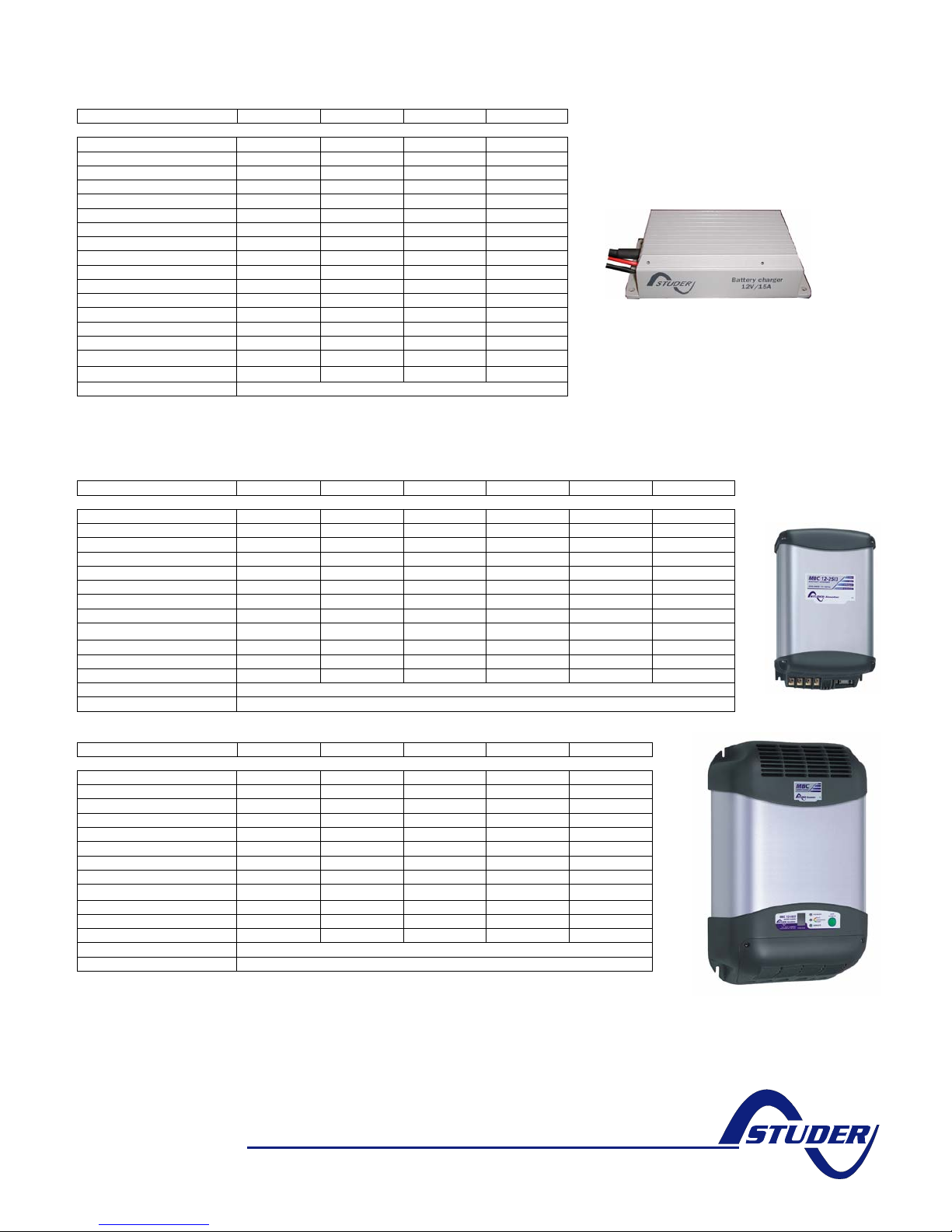
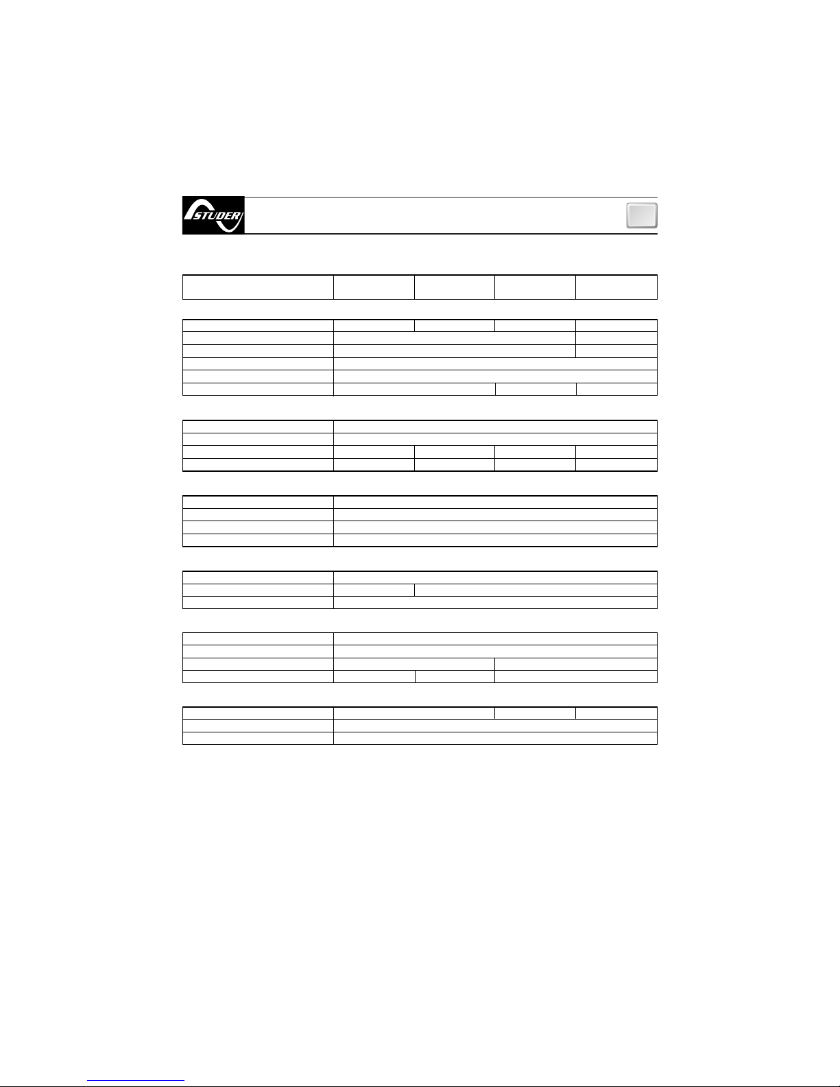
MBC Battery chargers, switch-mode, 3-STEP, IP65
Type MBC 12-06/1 MBC 12-15/1 MBC 24-03/1 MBC 24-08/1
Battery voltage (Vdc) 12 12 24 24
Input voltage (Vac) 100-260 100-260 100-260 100-260
Charge voltage (boost) 14.4 14.4 28.8 28.8
Charge voltage (float) 13.8 13.8 27.6 27.6
Output (Amp.) 6 15 3 8
Cooling Heat sink Heat sink Heat sink Heat sink
Outputs 1 1 1 1
Frequency 40-60 Hz 40-60 Hz 40-60 Hz 40-60 Hz
Efficiency > 85 % > 85 % > 85 % > 85 %
Ambient temp. range -25 to 50°C -25 to 50°C -25 to 50°C -25 to 50°C
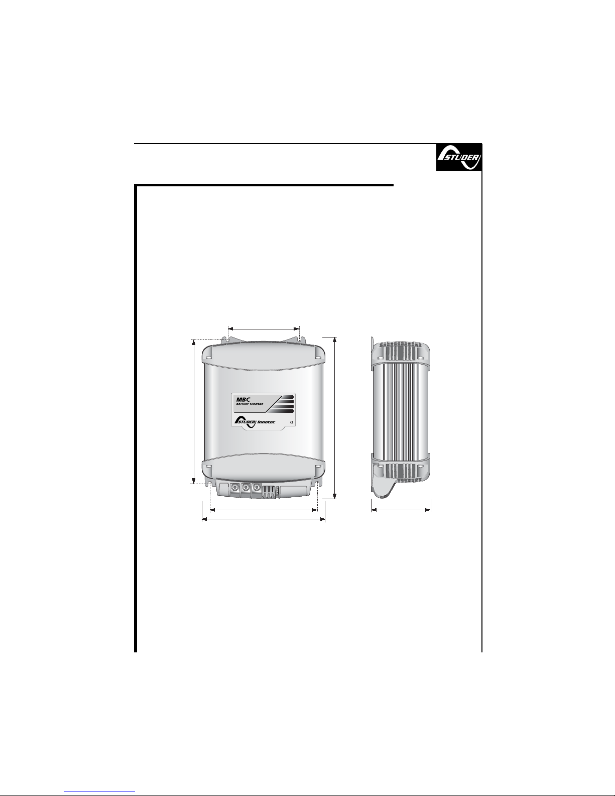
Dimensions lxwxh (mm) 155x80x36 195x100x47 155x80x36 195x100x46
Weight (kg) 0.9 1.8 0.9 1.8
Recommanded battery capacity 18-60 Ah 45-150 Ah 9-30 Ah 24-80 Ah
Switch over current (A) 0.17-0.23 0.68-0.92 0.17-0.23 0.34-0.46
Secondary fuse (A) 7.5 20 7.5 15
Input wired (Vac)
✔ ✔
✔ ✔
Output wired (Vdc)
✔
✔ ✔ ✔
Warranty 2 years
MBC 12-15/1
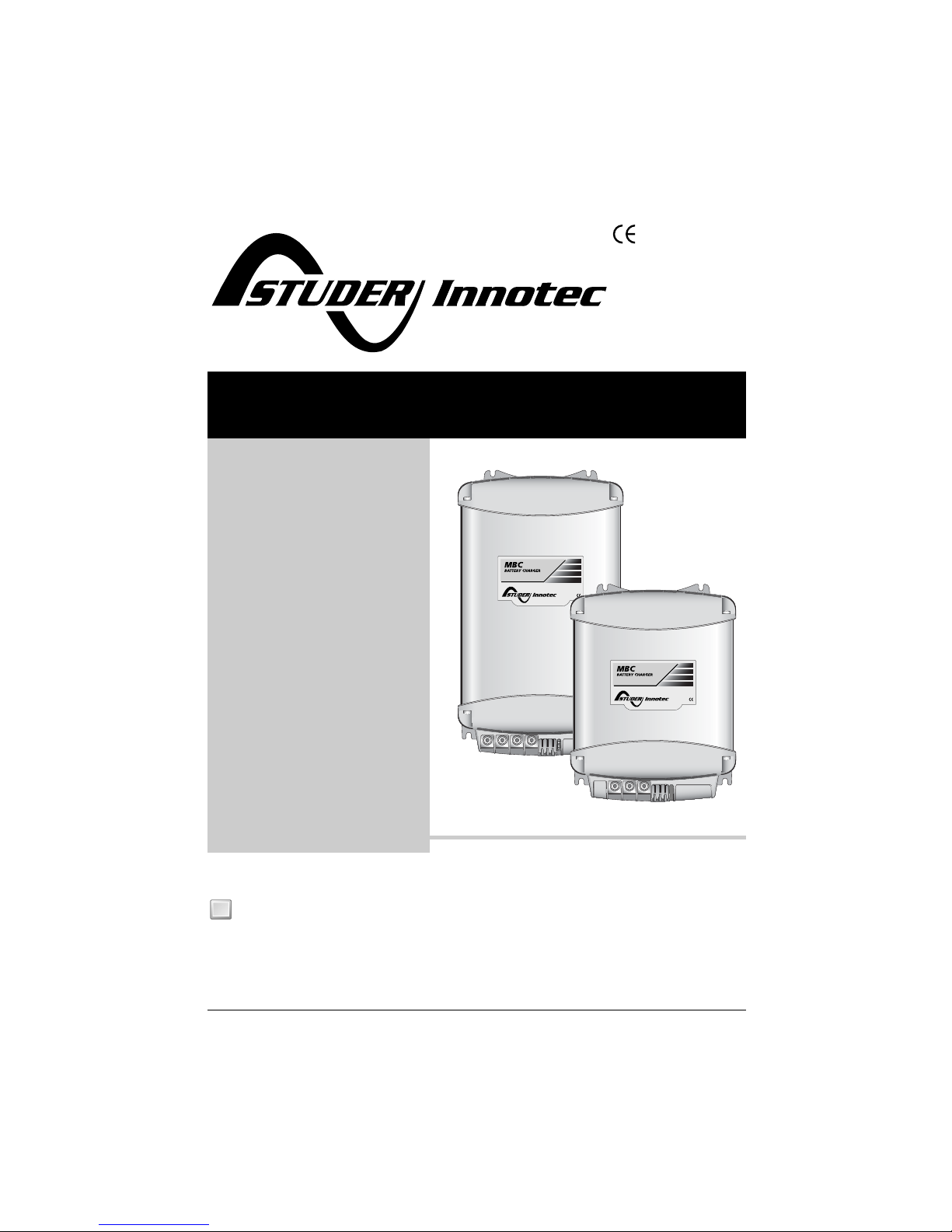
MBC Battery chargers, switch-mode, 3-STEP
Type MBC 12-08/2 MBC 12-12/2 MBC 12-25/3 MBC 12-30/3 MBC 12-40/3 MBC 12-60/3
Battery voltage (Vdc) 12 12 12 12 12 12
Input voltage (Vac) 115-230 115-230 115-230 83-280 83-280 83-280
Charge absorption volt. (Vdc) 14.1 (14.4*) 14.1 (14.4*) 14.1 (14.4*) 14.1 (14.4*) 14.1 (14.4*) 14.1 (14.4*)
Charge float voltage (Vdc) 13.5 (13.8*) 13.5 (13.8*) 13.5 (13.8*) 13.5 (13.8*) 13.5 (13.8*) 13.5 (13.8*)
Output (Amp.) 8 12 25 30 40 60
Cooling Natural Fan Fan Fan Fan Fan
Outputs 2 2 3 3 3 3
Frequency 45-66 Hz 45-66 Hz 45-66 Hz 45-66 Hz 45-66 Hz 45-66 Hz
PFC
✔ ✔ ✔
Ambient temp. range -20 to +70°C -20 to +70°C -20 to +70°C -20 to +70°C -20 to +70°C -20 to +70°C
Dimensions lxwxh (mm) 155x205x75 155x205x75 155x268x75 272x334x127 272x334x127 272x412x127
Weight (kg) 1.3 1.4 2.3 4.2 4.2 5.4
EMC class EN 55022/B
Warranty 2 years
* GEL batteries MBC 12-25/3
Type MBC 12-80/3 MBC 24-12/2 MBC 24-30/3 MBC 24-60/3 MBC 24-80/3
Battery voltage (Vdc) 12 24 24 24 24
Input voltage (Vac) 83-280 115-230 83-280 150-280 150-280
Charge voltage (boost) (Vdc) * 14.1 (14.4*) 28.2 (28.8*) 28.2 (28.8*) 28.2 (28.8*) 28.2 (28.8*)
Charge voltage (float) (Vdc) * 13.5 (13.8*) 27.0 (27.6*) 27.0 (27.6*) 27.0 (27.6*) 27.0 (27.6*)
Output (Amp.) 80 12 30 60 80
Cooling Fan Fan Fan Fan Fan
Outputs 3 2 3 3 3
Frequency 45-66 Hz 45-66 Hz 45-66 Hz 45-66 Hz 45-66 Hz
PFC
✔
✔
✔ ✔
Ambient temp. range -20 to +70°C -20 to +70°C -20 to +70°C -20 to +70°C -20 to +70°C
Dimensions lxwxh (mm) 272x495x127 155x268x75 272x412x127 272x495x127 272x495x127
Weight (kg) 7.1 2.3 5.4 7.1 7.1
EMC class EN 55022/B
Warranty 2 years
* GEL batteries
MBC 12-60/3
548/mbc
STUDER Innotec
Rue des Casernes 57
Tel. : + 41 (0) 27 205 60 80 info@studer-innotec.com
CH – 1950 Sion Fax : + 41 (0) 27 205 60 88 www.studer-innotec.com
Page 2

Pag. 1 MBC 12-08/2, 12-12/2, 12-25/3, 24-12/2
INDEX
Pag. 13 MBC 12-30/3, 12-40/3, 12-60/3, 24-30/3
Pag. 29 MBC 12-80/3, 24-60/3, 24-80/3
Page 3
REV 000
User’s Manual
MBC BATTERY CHARGER
MBC BATTERY CHARGER
MBC 12-08/2
MBC 12-12/2
MBC 12-25/3
MBC 24-12/2
GB
1
Page 4

2
Pag. 3-4 Characteristics and Installation
Pag. 5 Installation: voltage supply, batteries
Pag. 6 Installation: Selecting the charging
method
Pag. 7 Operation: Control signal,
Pag. 8 Ope characteristicsration: Charging
Pag. 9 Operation: Control panel - Maintenance
Pag. 10 Technical data
INDEX
GB
Page 5

CHARACTERISTICS AND INSTALLATION
GB
3
MBC BATTERY CHARGER SERIES BATTERY CHARGER
The long experience we have in the nautical field has given us the ability to evolve the range of MBC
battery chargers, now called MBC BATTERY CHARGER, with superior performance to those currently on the
market. The high level of performance of the MBC BATTERY CHARGER gives a charge to the batteries which
is both fast and safe.
Other important advantages which the MBC BATTERY CHARGER battery chargers offer, are:
• Three stage IUoU battery charging.
• Multiple outputs in order to charge more groups of batteries (internal battery isolator diodes).
• Charge selector for liquid/gel electrolyte batteries.
• Low residual fluctuation on output (ripple lower than 30 mV RMS).
• Compatible with every kind of generator.
• Short circuit, overloading, output overvoltage and overheating protection.
• Can work in a wide range of ambient temperatures.
INSTALLATION
BEFORE USING THE BATTERY CHARGER CAREFULLY READ THIS USER’S MANUAL. IN CASE OF
DOUBT CONTACT THE “STUDER INNOTEC” SUPPLIER OR AFTER SALES SERVICE DEPARTMENT.
THE BATTERY CHARGERS HAS BEEN DESIGNED FOR FIXED INSTALLATIONS (FOR INDOOR USE
ONLY).
“Studer Innotec” battery chargers have been designed and made for the reasons described in this
user’s manual. The “Studer Innotec” Company does not accept any responsibility for direct or
indirect damage caused by improper use of the equipment, bad installation or by possible errors
occurring in this manual.
THE OPENING OF THE BATTERY CHARGER BY UNAUTHORISED PERSONNEL MAKES THE
WARRANTY VOID.
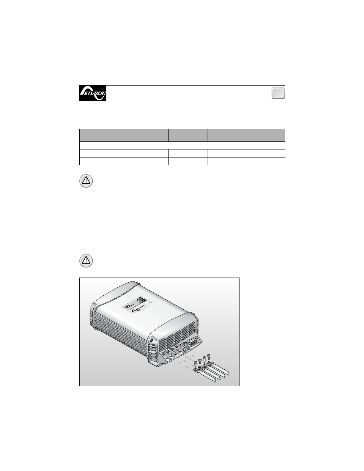
THE PACKAGE CONTAINS: battery charger - warranty card - user’s manual - cable terminals (to be
used for connection to the output terminals).
Page 6
CHARACTERISTICS AND INSTALLATION
GB
4
INSTALLATION SITE
Install the battery charger in a dry and ventilated place and as near to the batteries as possible. The
battery charger, although having high efficiency, develops a certain amount of heat during functioning, therefore, it is imperative that the installation area has sufficient ventilation, enough to allow use
of the equipment at maximum power.
The battery charger can be installed in a horizontal or vertical position with cables coming out in the
downward position. The vertical position is recommended because the natural convection of heat
helps to cool the equipment. The perimeter of the battery charger (except the base) must be kept at
a distance from walls or objects by a minimum of 5 cm.
FIG.1
The cables connected to the output terminals have a maximum length of 4 metres.
WARNING: the battery charger must be used only with a re-chargeable lead/liquid
electrolytic batteries or lead/gel (sealed or non-sealed).
WARNING: the outer surface of the battery charger is used as a heat sink, therefore it may
reach very high temperatures (risk of burns). Leave the equipment to cool down before
handling it.
MODEL
Battery voltage
Battery capacity
Minimum output cable size
MBC 12-08/2 MBC 12-12/2 MBC 12-25/3 MBC 24-12/2
12 V 24 V
35 ÷ 80 Ah 55 ÷ 120 Ah 110 ÷ 250 Ah 55 ÷ 120 Ah
4 mm
2
6 mm
2
10 mm
2
6 mm
2
EQUIPMENT REQUIRED FOR INSTALLATION
On the basis of the type of model, use the batteries and cables on the output terminals as specified
in the following table:
Page 7
5
INSTALLATION
GB
BATTERY
WARNING: during charge, batteries can generate explosive gases, therefore avoid sparks or
naked flames. Provide adequate ventilation to the battery area whilst charging.
WARNING: before connecting the batteries check the terminals of the cables from the battery. Reversing the terminals could seriously damage the battery charger even if protected by
fuses.
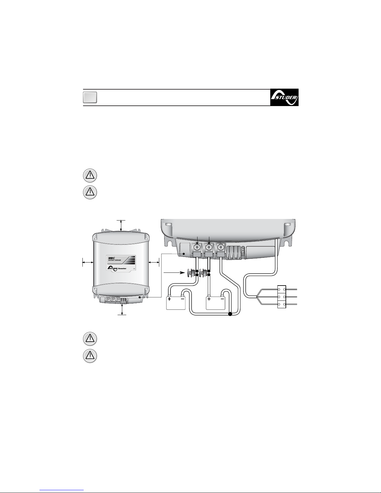
The positive terminal of the battery or of the group of batteries must be connected to one of the positive terminals of the battery charger. The negative terminal of the battery or of the group of batteries
must be connected to the negative terminal of the battery charger. To make the connections use the
cable terminals supplied with the equipment.
EQUIPMENT SUPPLY
The equipment already includes a power cable for AC supply. For connections to an AC supply see
fig.2. Before powering up the battery charger check that the power supply voltage, described on the
rating label, corresponds to that supplied by the AC supply source.
In the electrical circuit a two-pole switch must be installed for the sole use of switching the equipment ON & OFF.
The insulation between the contact points of the connections of the AC supply must be at least 3 mm.
The connections to the AC supply must be carried out according to local electrical codes.
WARNING: before connecting or disconnecting the cables from the electrical terminals of the battery charger, make sure that the equipment is disconnected from the AC mains and the batteries.
WARNING: in cases where the power cable could be damaged, have this changed by a “Studer
Innotec” service centre. In order to avoid accidents, the equipment must only be opened by authorised personnel.
5 cm
5 cm
5 cm 5 cm
FIG.2
battery
n° 2
battery
n° 1
Battery
switches
Blue
Yellow
Green
Brown
Neutral
Earth
Live
SLAVE A
MASTER
Page 8
6
INSTALLATION
GB
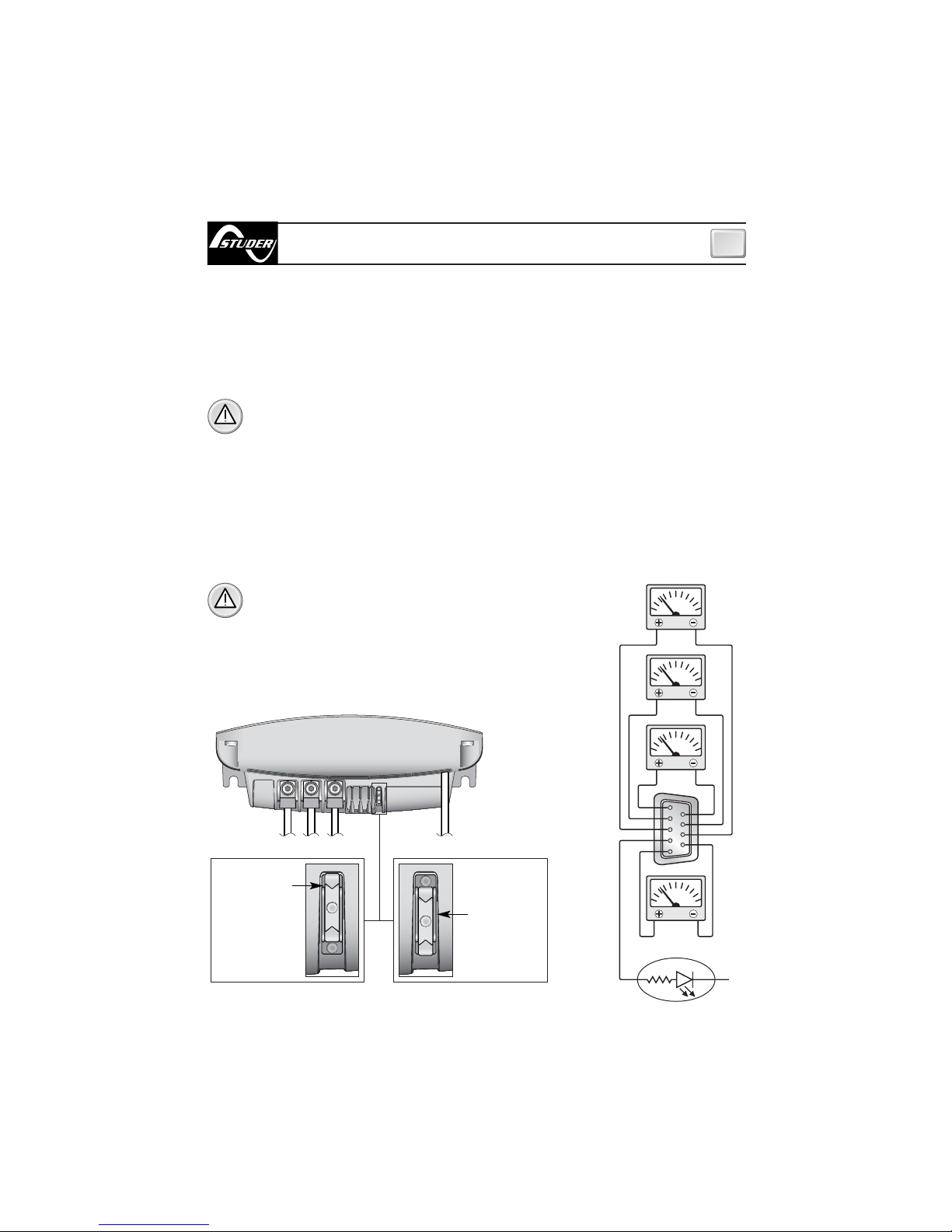
SELECTION OF THE CHARGING MODE
The battery charger can be set to optimize the charge according to the type of battery used, either
liquid or gel electrolytic. The selection of the type of charge is made via the switch placed in the terminal board area, as indicated in Fig.3a.
When charging liquid electrolytic, re-arrange the switch to position EL, for batteries with gel electrolytic to the position GEL.
A
V
V
V
2
1
8
9
3
4
5
6
7
5
4
9
-
V bat
1
27
38
6
MASTER
Slave A
Slave B
FIG.3 b
WARNING: check the charge mode. Incorrect selection
could cause shorter battery life or lengthen the charging time.
FIG.3 a
If the installation has only one or two groups of batteries, always connect the output marked “MASTER”. This is the main outlet of the battery charger.
If the “MASTER” is not connected, the battery charger may supply an output voltage lower than rated.
It is advisable to connect the group of batteries which are used more often (typically the service
group) to the MASTER output terminal.
The positive output terminals which are not used must be kept free (do not bridge the terminals).
WARNING: the use of inadequate size cables and incorrect connection of the terminals or
electrical joints may result in dangerous overheating of the connecting terminals or cables.
BATTERIES
WITH GEL
ELECTROLYTE
BATTERIES
WITH
LIQUID
ELECTROLYTE
TOTAL CURRENT
BASIC STATE
FIG.3.1 FIG.3.2
Page 9
7
OPERATING
GB
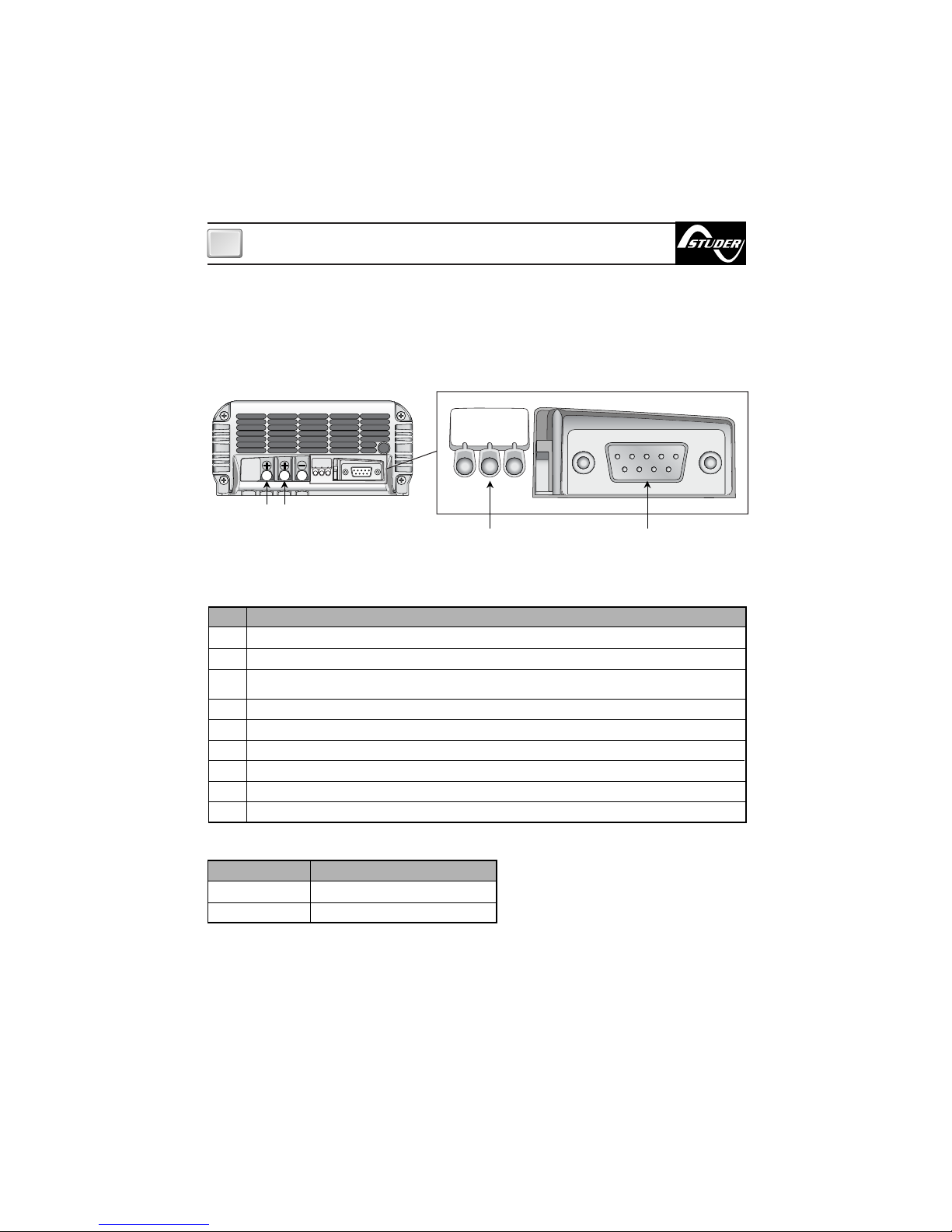
CONTROL SIGNALS (ONLY MBC 12-25/3)
The battery charger has a 9-pin female connector (connector DB9, see fig..4) on which the analog signals can be seen and used to monitor and control the equipment.
The position and description of the signals on the connector are listed below:
BASIC STATE OF BATTERY CHARGER
Description
Positive MASTER output (650mA max). By drawing 100mA the error is less than 0.7%.
Positive SLAVE A output (650mA max). By drawing 100mA the error is less than 0.7%.
Not connected or if it present, positive SLAVE B output (650mA max). By drawing 100mA the error is less
than 0.7%.
Basic state of battery charger (20 mA max).
Battery charger total current positive shunt (10 mA max). The transduction ratio is 100mV/100A.
GND signal 1 (V master).
GND signal 2 (V slave A).
GND signal 3 (V slave B, if it present).
Battery charger total current negative shunt.
Connection PIN 4
HIGH IMPEDENCE
+ V CHARGE
State
OFF or PROBLEMS
ON WITHOUT PROBLEMS
For a wiring example of control signals look at figure 3b.
Number
1
2
3
4
5
6
7
8
9
The position and description of the signals on the connector are listed below.
CHARGE
POWER
FLOAT
CHARGE
POWER
FLOAT
12345
6789
CONTROL PANEL LED SIGNAL CONTROL
CONNECTOR
FIG. 4
SLAVE A MASTER
Page 10
8
OPERATING
GB
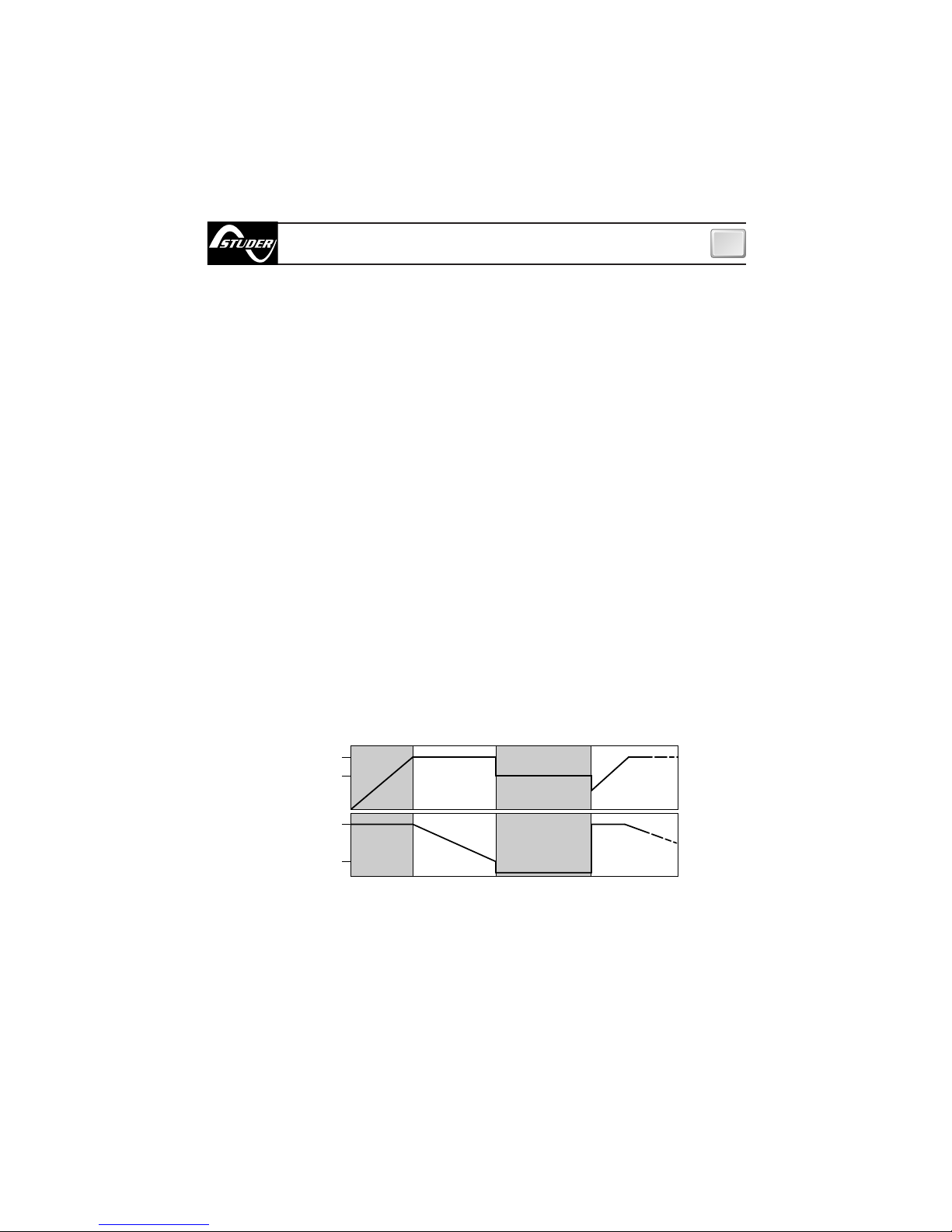
BULK phase (constant current) - The batteries need more current than the battery charger can supply. Current is limited to the maximum rated output. The battery charger can enter this phase during
start-up, when the batteries are low or when a high load is connected.
ABSORPTION phase (constant voltage) - The battery charger charges the batteries at a constant
ABSORPTION voltage and at the current they need.
The current needed by the batteries will tend to diminish over time. When the required current is less
than 20% of the maximum output value, the charger will change to the FLOAT phase.
FLOAT phase (maintenance) - The battery charger charges the batteries at the constant FLOAT voltage. In this phase, as the batteries reach maximum capacity, they will tend to absorb current close to
zero Ampere. This FLOAT phase will allow the batteries to be on charge without the risk of overloading. The next step to the ABSORPTION phase occurs when the demand for current goes over 20% of
the maximum output value.
CHARGING CHARACTERISTICS
Charging occurs in 3 phases:
OPERATION
When the battery charger is switched on, it automatically selects the optimum charge mode to
best suit the batteries or load connected. The battery charger has a loading characteristic of the
IUoU type.
(V)
14.1 (28.2) [Gel 14.4 (28.8)]
(I)
Imax
20% Imax
BULK ABSORPTION FLOAT NEW CYCLE
TIME
TIME
13.5 (27.0) [Gel 13.8 (27.6)]
Page 11
9
OPERATING - MAINTENANCE
GB
MAINTENANCE
The battery charger does not need any maintenance. To ensure optimum performance from the
equipment, once a year check the cables and the electrical connections.
CONTROL PANEL
The control panel is made-up of three LEDS:
POWER LED, FLOAT LED and CHARGE LED (BULK, ABSORPTION, see fig.4)
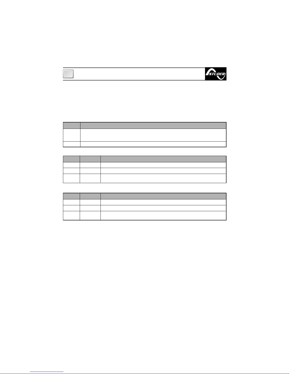
The information supplied by the LEDS are listed below:
POWER LED
FLOAT LED
LED Color
No indication
FLOAT phase - FLOAT charge
Short circuit or overload in output.
Check output cables, the group of batteries and the points of use connected to the battery charger.
LED Status
Description
LED Color
Off
No mains power or overheating.
In case of overheating check if the installation of the battery charger is correct.
Switch off and allow the equipment to cool down for at least 10 minutes.
Power ON
Green
Description
Off
Green
Green
Off
Fixed
Flashing
CHARGE LED (BULK, ABSORPTION)
LED Color
No indication
ABSORPTION phase or BULK phase
Short circuit or overload in output.
Check output cables, the group of batteries and the points of use connected to the battery charger.
LED Status
Description
Off
Yellow
Yellow
Off
Fixed
Flashing
Page 12
10
TECHNICAL DATA
GB
STUDER RESERVES THE RIGHT TO MODIFY THE TECHNICAL CHARACTERISTICS OF THE EQUIPMENT AND THE CONTENTS OF THIS MANUAL WITHOUT PRIOR NOTICE.
MODEL
MBC12-08/2 MBC12-12/2 MBC12-25/3 MBC24-12/2
MBC12-08/2 DR MBC12-12/2 DR MBC12-25/3 DR MBC24-12/2 DR
OUTPUT CHARACTERISTICS
Maximum output current
(1)
Charge absorption voltage
Charge float voltage
Residual ripple
(2)
Charging characteristics
Number of outputs
(3)
8 A 12 A 25 A 12 A
14,1 Vdc (14,4 Vdc GEL) 28,2 Vdc (28,8 Vdc GEL)
13,5 Vdc (13,8 Vdc GEL) 27,0 Vdc (27,6 Vdc GEL)
30mV RMS max
Automatic in three stages IUoU
232
Yes, through fuse
Yes
Yes
Yes
207÷260 Vac (207÷260 Vac or 103÷130 Vac
(5) (*)
)
45÷66 Hz
1,2 A 1,8 A 3,2 A 3,0 A
2,4 A 3,6 A 6,4 A 6,0 A
-20 to +70 °C,with power reduction over +50 °C
Natural Forced, with controlled fan (2 speed)
Max.95% RV without condensation
No Yes No
EN 60335-2-29
EN 55022/B
Aluminium - Cycoloy ®
Anodized - OR5066
155 x 205 x 75 mm 155 x 268 x 75 mm
1,3 Kg 1,4 Kg 2,3 Kg
INPUT CHARACTERISTICS
PROTECTION
Supply voltage
(4)
Frequency
Maximum absorption (230 Vac)
(6)
Maximum absorption (115 Vac)
(6) (*)
CASE
Material
Colour
Dimensions (WxHxD)
Weight
Reverse polarity
(7)
Overload
Output short circuit
Overheating
AMBIENT CHARACTERISTICS
Operating temperature
Cooling
Humidity
GENERAL
Connector for remote panel
Safety classification
EMC class
(*)
available early 2005
(1)
Maximum value at normal use or in short circuit.
(2)
At maximum output current on resistive load.
(3)
Each output can supply the maximum value of nominal current. The sum of the currents supplied from each output can not exceed
the maximum nominal value of the equipment.
(4)
Without power derating.
(5)
The battery charger measure the input AC voltage and choose the correct working input range.
(6)
With supply voltage specified as and output current equal to the maximum nominal value.
(7)
The protection could be inefficient in some operative conditions.
Cycoloy ® is a registered trade mark of GE Plastics.
TECHNICAL DATA
Page 13
205
181
90
135
155
75
MBC BATTERY CHARGER -
DIMENSIONS (mm)
12-08/2
12-12/2
11
Page 14

12
268
244
90
135
155
75
MBC BATTERY CHARGER -
DIMENSIONS (mm)
12-25/3
24-12/2
Page 15

REV 001
MBC BATTERY CHARGER
MBC 12-30/3
MBC 12-40/3
MBC 12-60/3
MBC 24-30/3
User’s Manual
MBC BATTERY CHARGER
GB
13
Page 16

14
Pag. 15 Characteristics and Installation
Pag. 17 Installation: voltage supply, batteries
Pag. 18 Installation: Selecting the charging
method
Pag. 19 Operation: Control signal,
Pag. 20 Operation: Charging characteristics
Pag. 21 Operation: Control panel
Pag. 22-23 Notification signs
Pag. 24-25 Programming the battery charger
Pag. 26 Maintenance - Technical data
INDEX
GB
Page 17

CHARACTERISTICS AND INSTALLATION
GB
MBC BATTERY CHARGER SERIES BATTERY CHARGER
The long experience we have in the nautical field has given us the ability to evolve the range of
MBC battery chargers, now called MBC BATTERY CHARGER, with superior performance to
those currently on the market. The high level of performance of the MBC BATTERY CHARGER
gives a charge to the batteries which is both fast and safe.
Other important advantages which the MBC BATTERY CHARGER battery chargers offer, are:
• Three stage IUoU battery charging.
• Multiple outputs in order to charge more groups of batteries (internal battery isolator diodes).
• Differentiated charging for liquid electrolite or gel batteries.
• Integrated fuses inside the battery chargers (one for each output).
• Thermal battery protection (with optional sensors).
• Ability of providing full output power with low supply voltage.
• The possibility of using the battery charger as a power supply without batteries.
• Low residual fluctuation on output (ripple lower than 30 mV RMS).
• Universal AC supply input (280 ÷ 83 Vac, 45 ÷ 66 Hz).
• Power factor (cos ϕ) equal to 1.
• Compatible with every kind of generator.
• Short circuit, overloading, output overvoltage and overheating protection.
• Can work in a wide range of ambient temperatures.
• Variable speed for the cooling fan.
• High-technology control panel.
• Automatic and manual half power mode.
• CAN BUS interface for data transfer.
• Case constructed in stainless steel, Cycoloy
®
.
INSTALLATION
BEFORE USING THE BATTERY CHARGER CAREFULLY READ THIS USER’S MANUAL.
IN CASE OF DOUBT CONTACT THE “STUDER INNOTEC” SUPPLIER OR AFTER SALES
SERVICE DEPARTMENT.
THE BATTERY CHARGERS HAS BEEN DESIGNED FOR FIXED INSTALLATIONS (FOR INDOOR
USE ONLY).
“Studer Innotec” battery chargers have been designed and made for the reasons described in
this user’s manual. The “Studer Innotec” Company does not accept any responsibility for direct
or indirect damage caused by improper use of the equipment, bad installation or by possible
errors occurring in this manual.
THE OPENING OF THE BATTERY CHARGER BY UNAUTHORISED PERSONNEL MAKES THE
WARRANTY VOID.
THE PACKAGE CONTAINS: battery charger - warranty card - user’s manual - cable terminals
(to be used for connection to the output terminals).
15
Page 18

INSTALLATION SITE
Install the battery charger in a dry and ventilated place and as near to the batteries as possible. The battery charger, although having high efficiency, develops a certain amount of heat
during functioning, therefore, it is imperative that the installation area has sufficient ventilation, enough to allow use of the equipment at maximum power.
The battery charger can be installed in a horizontal or vertical position with cables coming
out in the downward position. The vertical position is recommended because the natural
convection of heat helps to cool the equipment. The perimeter of the battery charger (except
the base) must be kept at a distance from walls or objects by a minimum of 5 cm.
CHARACTERISTICS AND INSTALLATION
GB
The cables connected to the output terminals have a maximum length of 4 metres.
WARNING: the battery charger must be used only with a re-chargeable lead/liquid
electrolytic batteries or lead/gel (sealed or non-sealed).
16
FIG.1
PART. A
PART. B
EQUIPMENT NECESSARY FOR INSTALLATION
On the basis of the type of model, use the batteries and cables on the output terminals as
specified in the following table:
MODEL
Battery voltage
Battery capacity
Minimum output cable size
MBC 12-30/3 MBC 12-40/3 MBC 12-60/3 MBC 24-30/3
12 V 24 V
140 ÷ 300 Ah 180 ÷ 400 Ah 270 ÷ 600 Ah 140 ÷ 300 Ah
10 mm
2
16 mm
2
25 mm
2
10 mm
2
Page 19

17
BATTERIES
To access the output terminals it is necessary to remove the cover by loosening the two screws
which hold it on top (see fig. 1 Part A). Before making the connections to the cables from the battery, loosen or remove the cable clamps by loosening the screws which fix it to the base (Fig.1
Part B).
WARNING: during charge, batteries can generate explosive gases, therefore avoid
sparks or naked flames. Provide adequate ventilation to the battery area whilst charging.
WARNING: before connecting the batteries check the terminals of the cables from the
battery. Reversing the terminals, could seriously damage the battery charger even if protected by fuses.
INSTALLATION
GB
EQUIPMENT SUPPLY
The equipment already includes a power cable for AC supply. For connections to an AC supply
see fig.2. Before powering up the battery charger check that the power supply voltage, described on the rating label, corresponds to that supplied by the AC supply source.
In the electrical circuit a two-pole switch must be installed for the sole use of switching the
equipment ON & OFF. The insulation between the contact points of the connections of the AC
supply must be at least 3 mm. The connections to the AC supply must be carried out according
to local electrical codes.
WARNING: before connecting or disconnecting the cables from the electrical terminals of
the battery charger, make sure that the equipment is disconnected from the AC mains and
the batteries.
WARNING: in cases where the power supply cable could be damaged, have this
changed by a “Studer Innotec” service centre. In order to avoid accidents, the equipment must only be opened by authorised personnel.
5 cm
5 cm
5 cm
5 cm
FIG.2
battery
n° 3
battery
n° 2
battery
n° 1
Battery switches
Blue
Yellow
Green
Brown
Neutral
Earth
Live
SLAVE B SLAVE A
MASTER
Page 20

18
INSTALLATION
GB
The positive terminal of the battery or of the group of batteries must be connected to one of the
positive terminals of the battery charger. The negative terminal of the battery or of the group of
batteries must be connected to the negative terminal of the battery charger. To make the connections use the cable terminals supplied with the equipment.
If the installation has only one or two groups of batteries, always connect the output marked
“MASTER”. This is the main outlet of the battery charger.
If the “MASTER” is not connected, the battery charger may supply an output lower voltage than
rated and therefore less power.
It is advisable to connect the group of batteries which are used more often (typically the service group) to the MASTER output terminal.
The positive output terminals that are not used must be kept free (do not bridge the terminals).
WARNING: the use of inadequate size cables and the incorrect connection of terminals
or electrical joints may result in dangerous overheating of the connecting terminals or
cables.
83
1
6
7
8
9
2
3
4
5
BASIC STATE
C
A
N
1
C
A
N
1
CONTROL SIGNALS
The battery charger is provided with a 9-pin female D-shell connector (DB9 connector, see
Fig. 3a) which indicates the signals which can be used for monitoring and controlling the
equipment.
FIG.3 a FIG.3 b
Page 21

19
IGB
OPERATING
BASIC STATE OF BATTERY CHARGER
FEMALE CONNECTOR (DB 9)
Description
CAN BUS terminator (124 ohm)
CANL signal - CAN BUS interface
Battery charger negative
Not used
Earth
Not used
CANH signal - CAN BUS interface
Basic state of the battery charger (+V output, 20mA max)
+5Vdc (10 mA max)
PIN 8 connection
HIGH IMPEDENCE
+V OUTPUT
State
OFF OR PROBLEMS PRESENT
ON OR NO PROBLEMS PRESENT
For a wiring example of control signals look at figure 3b.
CAN BUS NETWORK CONNECTION
When making the data interface connection (CANH and CANL signals) use an unscreened cable
with a twisted pair (cross-section 0.25/ 0.35 mm
2
AWG 22/24, impedance 100/150 ohm).
The maximum total length of the data signal cable should be no more than 100 m.
Activate the terminator at the first and last device connected to the network.
If there is only one device, the terminator does not need to be activated.
An example of a network connection is given below:
PIN
1
2
3
4
5
6
7
8
9
The position and description of the signals on the connector are listed below:
CAN-H(7)
CAN-L(2)
TERM(1)
CAN-H
CAN-L
TERM
CAN-H
CAN-L
TERM
CAN-H
CAN-L
TERM
*
Optional devices.
***
TEMPERATUR
BATTERIES
SENSOR
MBC
BATTERY
CHARGER
CURRENT
SENSOR
LCD
TERMINAL
Page 22

20
IGB
OPERATING
BULK phase (constant current) - The batteries need more current than the battery charger
can supply. Current is limited to the maximum rated output. The battery charger can enter this
phase during start-up, when the batteries are low or when a high load is connected.
ABSORPTION phase (constant voltage) - The battery charger charges the batteries at a constant ABSORPTION voltage and at the current they need.
The current needed by the batteries will tend to diminish over time. When the required current
is less than 20% of the maximum output value, the charger will change to the FLOAT phase.
FLOAT phase (maintenance) - The battery charger charges the batteries at the constant
FLOAT voltage. In this phase, as the batteries reach maximum capacity, they will tend to absorb
current close to zero Ampere. This FLOAT phase will allow the batteries to be on charge without the risk of overloading. The next step to the ABSORPTION phase occurs when the demand
for current goes over 20% of the maximum output value.
HALF-POWER MODE
If the supply voltage of the equipment drops under 97 Vac the battery charger will activate the
“half power” mode. In this mode the battery charger can supply, a maximum value half of the
maximum nominal output current. In this way you can reduce the current absorption from the
AC supply. This feature is useful when the battery charger is supplied via a generator or from a
dock outlet with limited power output.
The half power mode can be activated manually by using the remote LCD terminal (optional).
CHARGING CHARACTERISTICS
Charging occurs in 3 phases:
OPERATION
When the battery charger is switched on for a short period, all the LEDS on the front panel will
light up. After that the battery charger will place itself in the optimum charging mode to best suit
the batteries or load connected. The battery charger has a loading characteristic of the IUoU type.
The MBC battery chargers can also be used as a power supply, that is, with batteries disconnected.
We suggest you use the battery charger in this mode only occasionally and not for ordinary
use. However, avoid connecting high inductive loads (e.g. high powered motors) with the batteries disconnected as it you could cause damage to the equipment, even if rare to happen.
(V)
14.1 (28.2) [Gel 14.4 (28.8)]
(I)
Imax
20% Imax
BULK ABSORPTION FLOAT NEW CYCLE
TIME
TIME
13.5 (27.0) [Gel 13.8 (27.6)]
Page 23

21
GB
OPERATING
CONTROL PANEL
The control panel is made-up of three LED, a 7 segment display and a button:
POWER LED, CHARGE PHASE LED (BULK, ABSORPTION, FLOAT) ERROR LED, STATUS display
and ON/STAND-BY button (see fig.4).
CHARGE PHASE LED (BULK, ABSORPTION, FLOAT)
ERROR LED
Description
No output power
BULK phase - charge at constant current
ABSORPTION phase - charge at constant voltage
FLOAT phase - float charge
FIG.4
LED Colour
OFF
Red
Orange
Green
LED Colour
OFF
Red
Description
No problem with manual reset
Problem with manual reset (see error codes)
The information supplied by the LEDS are listed as below:
POWER LED
LED colour
OFF
Green
Flashing
Description
No mains power
Power ON
Battery charger in stand-by mode
ON/STAND-BY BUTTON:
Use this button to put the battery charger in stand-by mode. To activate this mode simply
press the button quickly (press and release in less than one second). To take the battery
charger out of stand-by mode, press the button quickly again or disconnect the battery charger from the AC power supply and then connect it up again.
Page 24

22
GB
NOTIFICATION SIGNS
The half-power mode has been activated by the manual control.
[ Flashing symbol ]. Monitor mode is activeted.
The AC mains voltage is too low. The battery charger goes into half-power mode.
The message disappears when the mains voltage falls within the nominal range
again. (This indication appears when the battery charger is turned off even under
normal voltage supply conditions).
The battery charger is reducing power because of a high ambient temperature. The
message disappears as soon as the condition which caused the problem is no
longer present. If this message appears frequently check whether the battery
charger has been installed properly.
The temperature measured by the battery sensors (optional) is outside the range
determined for the charge (-20/+55°C). The output voltage of the battery charger
becomes 12.8V (25.6V in the 24V models) so that the batteries are not damaged.
This message disappears when the battery temperature falls back within the correct range.
CAN BUS communication problem. The system has found a rate of communication
errors which is higher than normal.
If this message appears frequently, check whether the CAN network wiring has
been carried out properly.
NOTIFICATION SIGNS
PROBLEMS WITH AUTOMATIC RESET
Page 25

23
GB
NOTIFICATION SIGNS
The letter “E” and the number appear flashing on the display alternately.
Short circuit or output overload. Check the output wiring, the group of batteries and the load connected to the battery charger.
The letter “E” and the number appear flashing on the display alternately.
Output fuse blown (probable reverse polarity).
The letter “E” and the number appear flashing on the display alternately.
Output overvoltage. Due to internal malfunctioning, the battery charger supplied a voltage more than 12% of the nominal value for a very brief time.
The letter “E” and the number appear flashing on the display alternately. The
battery charger overheats excessively. The operating temperature of the battery charger has exceeded the maximum allowable threshold for proper operation. Check whether the battery charger has been installed properly. Turn off
the equipment and leave it to cool down for at least 10 minutes.
The letter “E” and the number appear flashing on the display alternately.
Prolonged overload. The battery charger has delivered maximum current at a
voltage lower than half the nominal output value for too long.
Check the output wiring, the group of batteries and the load connected to the
battery charger.
Error indication reserved for future expansions.
The letter “E” and the number appear flashing on the display alternating.
Serious CAN BUS communication problem. Check the CAN network wiring and
make sure the terminals have been installed properly.
PROBLEMS WITH MANUAL RESET
THE E2/E3 PROBLEMS NEED TO BE CHECKED BY A “STUDER INNOTEC” SERVICE CENTRE.
In order to eliminate the problems with manual reset you must remove the cause of the problem,
therefore, switch off the battery charger for at least 10 seconds and then switch it back on again.
Page 26

24
GB
PROGRAMMING THE BATTERY CHARGER
PROGRAMMING THE BATTERY CHARGER
The battery charger has the following programmable functions:
• Selecting the battery charge mode - liquid or gel electrolite.
• Selecting the network group.
• Selecting the priority within the network group.
• Activating/inactivating the monitor mode.
Activating programming
Press the button provided on the control panel for 6 seconds in order to activate the programming procedure. Once this time has elapsed, the letter “ " will appear steady on the display.
At this point, release the button. The battery charger will pass from one programming function
to another in the order given below:
EL/GEL SELECTION
This function enables the charge provided by the battery charger to be optimized according to
the type of batteries used - liquid electrolite or gel.
WARNING: check which battery charging mode has been selected. If the wrong selec-
tion is made, this could reduce the service life of the batteries or mean the charging
time takes longer.
The letter “ ” (liquid Electrolyte) or “ ” (gel) will appear flashing on the display according to the
current setting.
To change the setting press the key quickly (press and release the button in less than 1 second).
To make the setting operative press the key for at least 2 seconds. The display will confirm the
setting by showing the letter selected for one second (steady).
SELECTING THE NETWORK GROUP
This function enables the user to determine which network group the battery charger belongs to
(group “ ”, “ ” o “ ”). Only one battery charger of the MBC BATTERY CHARGER series can belong to each group. The other devices making up the group can be terminals, sensors or interfaces. A diagram is given below showing an example of a possible network:
GROUP A GROUP B
GROUP U
CAN NETWORK
LED
TERMINAL
TEMPERATURE
SENSOR,
BATTERIES 1
TEMPERATURE
SENSOR,
BATTERIES 2
TEMPERATURE
SENSOR,
BATTERIES 3
CURRENT
SENSOR
TEMPERATURE
SENSOR,
BATTERIES 1
LED
TERMINAL
CURRENT
SENSOR
GSM
INTERFACE
LCD
TERMINAL
MBC 12-60/3
MBC 24-30/3
Page 27

25
GB
BATTERY CHARGER PROGRAMMING
The devices belonging to one group “ ”, “ ” or “ ” can only dialog between themselves.
Group “ ” (Universal) is an exception as this can dialog with any other device.
The distinction between different groups is very important in order to connect all the devices to
the same CAN network even if they belong to different electrical systems.
The letter “ ” , “ ” or “ ”, will appear flashing on the display according to the current setting.
To change the setting, press the key quickly ( press and release the key in less than 1
second).
To make the setting operative press the key for at least 2 seconds. The display will confirm the
setting by showing the letter selected for one second (steady).
SELECTING GROUP ORDER OF PRIORITY
This function is used to determine the priority level of the battery charger within the network
group. At the moment this function is not used by the battery charger (it is reserved for future expansions).
The number “ ” , “ ” or “ ” will appear flashing on the display according to the current setting.
To change the setting press the key quickly (press and release the key in less than 1 second).
To make the setting operative press the key for at least 2 seconds. The display will confirm the
setting by showing the number selected for one second (steady).
Once the programming procedure has been completed, the following symbol will be shown for
1 second: “ “.
ACTIVATING/INACTIVATING THE MONITOR MODE
This function enables the user to activate or inactivate the battery charger’s “monitor” mode.
If it is activated, the “monitor” mode enables the battery charger to transmit and receive data
on the CAN network even if no AC power is being delivered. To do this, the battery charger is
supplied with power from the group of batteries using the master output. The current absorption, with “monitor” mode active, is less than 75mA (120mA for 24V models).
The battery charger exits “monitor” mode (is turned off) if the voltage of the master group of
batteries is less than 7Vdc (14Vdc for the 24V models).
This mode should be activated when the remote terminals are connected to the CAN network.
The letter “ ” (monitor mode Off) or “ ” (monitor mode On [Stand-by]), will appear flashing
on the display according to the current setting.
To change the setting press the key quickly (press and release in less than 1 second).
To make the setting operative press the key for at least 2 seconds. The display will confirm the
setting by showing the letter selected for one second (steady).
Page 28

26
GB
MAINTENANCE - TECHNICAL DATA
STUDER RESERVES THE RIGHT TO MODIFY THE TECHNICAL CHARACTERISTICS OF THE EQUIPMENT AND THE CONTENTS OF THIS MANUAL WITHOUT PRIOR NOTICE.
MODEL
MBC12-30/3 MBC12-40/3 MBC12-60/3 MBC24-30/3
OUTPUT CHARACTERISTICS
Maximum output current
(1)
Charge absorption voltage
Charge float voltage
Residual ripple
(2)
Charging characteristics
Number of outputs
(3)
30 A 40 A 60 A 30 A
14,1 Vdc (14,4 Vdc GEL) 28,2 Vdc (28,8 Vdc GEL)
13,5 Vdc (13,8 Vdc GEL) 27,0 Vdc (27,6 Vdc GEL)
30mV RMS max
Automatic in three stages IUoU
3
Yes, through fuse
Yes
Yes
Yes
Yes
Yes, optional
83÷280 Vac, with power reduction under 97 Vac
45÷66 Hz
2,5 A 3,3 A 4,8 A 4,5 A
5,1 A 6,8 A 9,8 A 9,5 A
1
-20 to +70 °C, with power reduction over +50 °C
Automatic , by variable speed cooling fan
Max. 95% RV without condensation
Yes
EN 60335-2-29
EN 55022/B
Stainless steel - Cycoloy ®
Polished steel - OR5066
272 x 334 x 127 mm 272 x 412 x 127 mm
4,2 Kg 5,4 kg
INPUT CHARACTERISTICS
PROTECTION
Supply voltage
Frequency
Maximum absorption (230 Vac)
(4)
Maximum absorption (115 Vac)
(4)
Power factor (cos ϕ)
CASE
Material
Colour
Dimensions (WxHxD)
Weight
Reverse polarity
(5)
Overload
Output short circuit
Overvoltage in output
(6)
Overheating
Battery overtemperature
AMBIENT CHARACTERISTICS
Operating temperature
Cooling
Humidity
GENERAL
Connector for remote panel
Safety classification
EMC class
(1)
Maximum value at normal use or in short circuit.
(2)
At maximum output current on resistive load.
(3)
Each output can supply the maximum value of nominal current. The sum of the currents supplied from each output can not exceed
the maximum nominal value of the equipment.
(4)
With supply voltage as specified and output current equal to the maximum nominal value
(5)
Protection may be inefficient in some operative conditions.
(6)
Software/hardware double-check.
Cycoloy ® is a registered trade mark of GE Plastics.
MAINTENANCE
The battery charger does not need any maintenance. To ensure optimum performance from
the equipment, once a year check the cables and the electrical connections.
TECHNICAL DATA
Page 29

280
334
272
220
127
MBC BATTERY CHARGER -
DIMENS IO NS (mm)
12-30/3 - 12-40/3
27
Page 30

28
358
412
272
220
127
MBC BATTERY CHARGER -
DIMENS IO N S (mm)
12-60/3 - 24-30/3
Page 31

REV 000
User’s Manual
MBC BATTERY CHARGER
GB
MBC BATTERY CHARGER
MBC 12-80/3
MBC 24-60/3
MBC 24-80/3
29
Page 32

30
Pag. 30-31 Characteristics and Installation
Pag. 32 Installation: voltage supply, batteries
Pag. 32 Installation: Selecting the charging method
Pag. 33 Operation: Control signal
Pag. 35 Operation: Charging characteristics
Pag. 36 Operation: Control panel
Pag. 37-38 Notification signs
Pag. 39-40 Battery charger programming
Pag. 41 Maintenance - Technical data
INDEX
GB
Page 33

CHARACTERISTICS AND INSTALLATION
GB
MBC BATTERY CHARGER SERIES BATTERY CHARGER
The long experience we have in the nautical field has given us the ability to evolve the range of
MBC battery chargers, now called MBC BATTERY CHARGER, with superior performance to
those currently on the market. The high level of performance of the MBC BATTERY CHARGER
gives a charge to the batteries which is both fast and safe.
Other important advantages which the MBC BATTERY CHARGER battery chargers offer, are:
• Three stage IUoU battery charging.
• Multiple outputs in order to charge more groups of batteries (internal battery isolator diodes).
• Differentiated charging for liquid electrolite or gel batteries.
• Integrated fuses inside the battery chargers (one for each output).
• Thermal battery protection (with optional sensors).
• Ability of providing full output power with low supply voltage.
• The possibility of using the battery charger as a power supply without batteries.
• Low residual fluctuation on output (ripple lower than 30 mV RMS).
• Universal AC supply input (only MBC 12-80/8).
• Power factor (cos ϕ) equal to 1.
• Compatible with every kind of generator.
• Short circuit, overloading, output overvoltage and overheating protection.
• Can work in a wide range of ambient temperatures.
• Variable speed for the cooling fan.
• High-technology control panel.
• Automatic and manual half power mode.
• CAN BUS interface for data transfer.
• Case constructed in stainless steel, Cycoloy
®
.
INSTALLATION
BEFORE USING THE BATTERY CHARGER CAREFULLY READ THIS USER’S MANUAL. IN CASE
OF DOUBT CONTACT THE “STUDER INNOTEC” SUPPLIER OR AFTER SALES SERVICE DEPARTMENT.
THE BATTERY CHARGERS HAS BEEN DESIGNED FOR FIXED INSTALLATIONS (FOR INDOOR
USE ONLY).
“STUDER INNOTEC” battery chargers have been designed and made for the reasons described
in this user’s manual. The “STUDER INNOTEC” Company does not accept any responsibility for
direct or indirect damage caused by improper use of the equipment, bad installation or by possible errors occurring in this manual.
THE OPENING OF THE BATTERY CHARGER BY UNAUTHORISED PERSONNEL MAKES THE
WARRANTY VOID.
THE PACKAGE CONTAINS: battery charger - warranty card - user’s manual - cable terminals
(to be used for connection to the output terminals).
31
Page 34

INSTALLATION SITE
Install the battery charger in a dry and ventilated place and as near to the batteries as possible. The battery charger, although having high efficiency, develops a certain amount of heat
during functioning, therefore, it is imperative that the installation area has sufficient ventilation, enough to allow use of the equipment at maximum power.
The battery charger can be installed in a horizontal or vertical position with cables coming
out in the downward position. The vertical position is recommended because the natural
convection of heat helps to cool the equipment. The perimeter of the battery charger (except
the base) must be kept at a distance from walls or objects by a minimum of 5 cm.
CHARACTERISTICS AND INSTALLATION
GB
The cables connected to the output terminals have a maximum length of 4 metres.
WARNING: the battery charger must be used only with a re-chargeable lead/liquid
electrolytic batteries or lead/gel (sealed or non-sealed).
32
FIG.1
PART. A
PART. B
EQUIPMENT NECESSARY FOR INSTALLATION
On the basis of the type of model, use the batteries and cables on the output terminals as
specified in the following table:
MODEL
Battery voltage
Battery capacity
Minimum output cable size
MBC 12-80/3 MBC 24-60/3 MBC 24-80/3
12 V 24 V
360 ÷ 800 Ah 270 ÷ 600 Ah 360 ÷ 800 Ah
35 mm
2
25 mm
2
35 mm
2
Page 35

33
BATTERIES
To access the output terminals it is necessary to remove the cover by loosening the two screws
which hold it on top (see fig. 1 Part A). Before making the connections to the cables from the battery, loosen or remove the cable clamps by loosening the screws which fix it to the base (Fig.1
Part B).
WARNING: during charge, batteries can generate explosive gases, therefore avoid
sparks or naked flames. Provide adequate ventilation to the battery area whilst charging.
WARNING: before connecting the batteries check the terminals of the cables from the
battery. Reversing the terminals, could seriously damage the battery charger even if protected by fuses.
INSTALLATION
GB
EQUIPMENT SUPPLY
The equipment already includes a power cable for AC supply. For connections to an AC supply
see fig.2. Before powering up the battery charger check that the power supply voltage, described on the rating label, corresponds to that supplied by the AC supply source.
In the electrical circuit a two-pole switch must be installed for the sole use of switching the
equipment ON & OFF. The insulation between the contact points of the connections of the AC
supply must be at least 3 mm.The connections to the AC supply must be carried out according
to local electrical codes.
WARNING: before connecting or disconnecting the cables from the electrical terminals of
the battery charger, make sure that the equipment is disconnected from the AC mains and
the batteries.
WARNING: in cases where the power supply cable could be damaged, have this
changed by a “STUDER INNOTEC” service centre. In order to avoid accidents, the equipment must only be opened by authorised personnel.
5 cm
5 cm
5 cm
5 cm
FIG.2
battery
n° 3
battery
n° 2
battery
n° 1
Battery switches
Blue
Yellow
Green
Brown
Neutral
Earth
Live
SLAVE B SLAVE A
MASTER
Page 36

34
INSTALLATION
GB
The positive terminal of the battery or of the group of batteries must be connected to one of the
positive terminals of the battery charger. The negative terminal of the battery or of the group of
batteries must be connected to the negative terminal of the battery charger. To make the connections use the cable terminals supplied with the equipment.
If the installation has only one or two groups of batteries, always connect the output marked
“MASTER”.This is the main outlet of the battery charger.
If the “MASTER” is not connected, the battery charger may supply an output lower voltage than
rated and therefore less power.
It is advisable to connect the group of batteries which are used more often (typically the service group) to the MASTER output terminal.
The positive output terminals that are not used must be kept free (do not bridge the terminals).
WARNING: the use of inadequate size cables and the incorrect connection of terminals
or electrical joints may result in dangerous overheating of the connecting terminals or
cables.
83
1
6
7
8
9
2
3
4
5
BASIC STATE
C
A
N
1
C
A
N
1
CONTROL SIGNALS
The battery charger is provided with a 9-pin female D-shell connector (DB9 connector, see
Fig. 3a) which indicates the signals which can be used for monitoring and controlling the
equipment.
FIG.3 a FIG.3 b
Page 37

35
IGB
OPERATING
BASIC STATE OF BATTERY CHARGER
FEMALE CONNECTOR (DB 9)
Description
CAN BUS terminator (124 ohm)
CANL signal - CAN BUS interface
Battery charger negative
Not used
Earth
Not used
CANH signal - CAN BUS interface
Basic state of the battery charger (+V output, 20mA max)
+5Vdc (5mA max)
PIN 8 connection
HIGH IMPEDENCE
+V OUTPUT
State
OFF OR PROBLEMS PRESENT
ON OR NO PROBLEMS PRESENT
For a wiring example of control signals look at figure 3b.
CAN BUS NETWORK CONNECTION
When making the data interface connection (CANH and CANL signals) use an unscreened cable
with a twisted pair (cross-section 0.25/ 0.35 mm
2
AWG 22/24, impedance 100/150 ohm).
The maximum total length of the data signal cable should be no more than 100 m.
Activate the terminator at the first and last device connected to the network.
If there is only one device,the terminator does not need to be activated.
An example of a network connection is given below:
PIN
1
2
3
4
5
6
7
8
9
The position and description of the signals on the connector are listed below:
CAN-H(7)
CAN-L(2)
TERM(1)
CAN-H
CAN-L
TERM
CAN-H
CAN-L
TERM
CAN-H
CAN-L
TERM
*
Optional devices.
***
TEMPERATUR
BATTERIES
SENSOR
MBC
CURRENT
SENSOR
LCD
TERMINAL
Page 38

36
IGB
OPERATING
BULK phase (constant current) - The batteries need more current than the battery charger
can supply. Current is limited to the maximum rated output. The battery charger can enter this
phase during start-up,when the batteries are low or when a high load is connected.
ABSORPTION phase (constant voltage) - The battery charger charges the batteries at a constant ABSORPTION voltage and at the current they need.
The current needed by the batteries will tend to diminish over time.When the required current
is less than 20% of the maximum output value,the charger will change to the FLOAT phase.
FLOAT phase (maintenance) - The battery charger charges the batteries at the constant
FLOAT voltage. In this phase, as the batteries reach maximum capacity, they will tend to absorb
current close to zero Ampere. This FLOAT phase will allow the batteries to be on charge without the risk of overloading. The next step to the ABSORPTION phase occurs when the demand
for current goes over 20% of the maximum output value.
HALF-POWER MODE
If the supply voltage of the equipment drops under 97 Vac the battery charger will activate the
“half power” mode. In this mode the battery charger can supply, a maximum value half of the
maximum nominal output current. In this way you can reduce the current absorption from the
AC supply. This feature is useful when the battery charger is supplied via a generator or from a
dock outlet with limited power output.
The half power mode can be activated manually by using the remote LCD terminal (optional).
CHARGING CHARACTERISTICS
Charging occurs in 3 phases:
OPERATION
When the battery charger is switched on for a short period, all the LEDS on the front panel will
light up.After that the battery charger will place itself in the optimum charging mode to best suit
the batteries or load connected.The battery charger has a loading characteristic of the IUoU type.
The MBC battery chargers can also be used as a power supply, that is, with batteries disconnected.
We suggest you use the battery charger in this mode only occasionally and not for ordinary
use. However, avoid connecting high inductive loads (e.g. high powered motors) with the batteries disconnected as it you could cause damage to the equipment, even if rare to happen.
(V)
14.1 (28.2) [Gel 14.4 (28.8)]
(I)
Imax
20% Imax
BULK ABSORPTION FLOAT NEW CYCLE
TIME
TIME
13.5 (27.0) [Gel 13.8 (27.6)]
Page 39

37
GB
OPERATING
CONTROL PANEL
The control panel is made-up of three LED,a 7 segment display and a button:
POWER LED, CHARGE PHASE LED (BULK, ABSORPTION, FLOAT) ERROR LED, STATUS display
and ON/STAND-BY button (see fig.4).
CHARGE PHASE LED (BULK, ABSORPTION, FLOAT)
ERROR LED
Description
No output power
BULK phase - charge at constant current
ABSORPTION phase - charge at constant voltage
FLOAT phase - float charge
FIG.4
LED Colour
OFF
Red
Orange
Green
LED Colour
OFF
Red
Description
No problem with manual reset
Problem with manual reset (see error codes)
The information supplied by the LEDS are listed as below:
POWER LED
LED colour
OFF
Green
Flashing
Description
No mains power
Power ON
Battery charger in stand-by mode
ON/STAND-BY BUTTON:
Use this button to put the battery charger in stand-by mode. To activate this mode simply
press the button quickly (press and release in less than one second). To take the battery
charger out of stand-by mode, press the button quickly again or disconnect the battery charger from the AC power supply and then connect it up again.
Page 40

38
GB
NOTIFICATION SIGNS
The half-power mode has been activated by the manual control.
[ Flashing symbol ]. Monitor mode is activeted.
The AC mains voltage is too low. The battery charger goes into half-power mode.
The message disappears when the mains voltage falls within the nominal range
again. (This indication appears when the battery charger is turned off even under
normal voltage supply conditions).
The battery charger is reducing power because of a high ambient temperature.The
message disappears as soon as the condition which caused the problem is no
longer present. If this message appears frequently check whether the battery
charger has been installed properly.
The temperature measured by the battery sensors (optional) is outside the range
determined for the charge (-20/+55°C). The output voltage of the battery charger
becomes 12.8V (25.6V in the 24V models) so that the batteries are not damaged.
This message disappears when the battery temperature falls back within the correct range.
CAN BUS communication problem. The system has found a rate of communication
errors which is higher than normal.
If this message appears frequently, check whether the CAN network wiring has
been carried out properly.
NOTIFICATION SIGNS
PROBLEMS WITH AUTOMATIC RESET
Page 41

39
GB
NOTIFICATION SIGNS
The letter “E”and the number appear flashing on the display alternately.
Short circuit or output overload. Check the output wiring, the group of batteries and the load connected to the battery charger.
The letter “E”and the number appear flashing on the display alternately.
Output fuse blown (probable reverse polarity).
The letter “E”and the number appear flashing on the display alternately.
Output overvoltage. Due to internal malfunctioning, the battery charger supplied a voltage more than 12% of the nominal value for a very brief time.
The letter “E” and the number appear flashing on the display alternately. The
battery charger overheats excessively. The operating temperature of the battery charger has exceeded the maximum allowable threshold for proper operation. Check whether the battery charger has been installed properly. Turn off
the equipment and leave it to cool down for at least 10 minutes.
The letter “E”and the number appear flashing on the display alternately.
Prolonged overload. The battery charger has delivered maximum current at a
voltage lower than half the nominal output value for too long.
Check the output wiring, the group of batteries and the load connected to the
battery charger.
The letter “E”and the number appear flashing on the display alternately.
Blocked fan.
The letter “E”and the number appear flashing on the display alternating.
Serious CAN BUS communication problem. Check the CAN network wiring and
make sure the terminals have been installed properly.
PROBLEMS WITH MANUAL RESET
THE E2/E3 PROBLEMS NEED TO BE CHECKED BY A “STUDER INNOTEC” SERVICE CENTRE.
In order to eliminate the problems with manual reset you must remove the cause of the problem,
therefore,switch off the battery charger for at least 10 seconds and then switch it back on again.
Page 42

40
GB
PROGRAMMING THE BATTERY CHARGER
PROGRAMMING THE BATTERY CHARGER
The battery charger has the following programmable functions:
• Selecting the battery charge mode - liquid or gel electrolite.
• Selecting the network group.
• Selecting the priority within the network group.
• Activating/inactivating the monitor mode.
Activating programming
Press the button provided on the control panel for 6 seconds in order to activate the programming procedure. Once this time has elapsed, the letter “ " will appear steady on the display.
At this point, release the button. The battery charger will pass from one programming function
to another in the order given below:
EL/GEL SELECTION
This function enables the charge provided by the battery charger to be optimized according to
the type of batteries used - liquid electrolite or gel.
WARNING: check which battery charging mode has been selected. If the wrong selec-
tion is made, this could reduce the service life of the batteries or mean the charging
time takes longer.
The letter “ ” (liquid Electrolyte) or “ ” (gel) will appear flashing on the display according to the
current setting.
To change the setting press the key quickly (press and release the button in less than 1 second).
To make the setting operative press the key for at least 2 seconds. The display will confirm the
setting by showing the letter selected for one second (steady).
SELECTING THE NETWORK GROUP
This function enables the user to determine which network group the battery charger belongs to
(group “ ”, “ ” o “ ”). Only one battery charger of the MBC BATTERY CHARGER series can belong to each group. The other devices making up the group can be terminals, sensors or interfaces.A diagram is given below showing an example of a possible network:
GROUP A GROUP B
GROUP U
CAN NETWORK
LED
TERMINAL
TEMPERATURE
SENSOR,
BATTERIES 1
TEMPERATURE
SENSOR,
BATTERIES 2
TEMPERATURE
SENSOR,
BATTERIES 3
CURRENT
SENSOR
TEMPERATURE
SENSOR,
BATTERIES 1
LED
TERMINAL
CURRENT
SENSOR
GSM
INTERFACE
LCD
TERMINAL
MBC MBC
Page 43

41
GB
BATTERY CHARGER PROGRAMMING
The devices belonging to one group “ ”, “ ” or “ ” can only dialog between themselves.
Group “ ” (Universal) is an exception as this can dialog with any other device.
The distinction between different groups is very important in order to connect all the devices to
the same CAN network even if they belong to different electrical systems.
The letter “ ” ,“ ” or “ ”, will appear flashing on the display according to the current setting.
To change the setting, press the key quickly ( press and release the key in less than 1
second).
To make the setting operative press the key for at least 2 seconds. The display will confirm the
setting by showing the letter selected for one second (steady).
SELECTING GROUP ORDER OF PRIORITY
This function is used to determine the priority level of the battery charger within the network
group.At the moment this function is not used by the battery charger (it is reserved for future expansions).
The number “ ” , “ ” or “ ” will appear flashing on the display according to the current setting.
To change the setting press the key quickly (press and release the key in less than 1 second).
To make the setting operative press the key for at least 2 seconds. The display will confirm the
setting by showing the number selected for one second (steady).
Once the programming procedure has been completed, the following symbol will be shown for
1 second: “ “.
ACTIVATING/INACTIVATING THE MONITOR MODE
This function enables the user to activate or inactivate the battery charger’s “monitor” mode.
If it is activated, the “monitor” mode enables the battery charger to transmit and receive data
on the CAN network even if no AC power is being delivered. To do this, the battery charger is
supplied with power from the group of batteries using the master output. The current absorption, with “monitor” mode active, is less than 75mA (120mA for 24V models).
The battery charger exits “monitor” mode (is turned off) if the voltage of the master group of
batteries is less than 7Vdc (14Vdc for the 24V models).
This mode should be activated when the remote terminals are connected to the CAN network.
The letter “ ” (monitor mode Off) or “ ” (monitor mode On [Stand-by]), will appear flashing
on the display according to the current setting.
To change the setting press the key quickly (press and release in less than 1 second).
To make the setting operative press the key for at least 2 seconds. The display will confirm the
setting by showing the letter selected for one second (steady).
Page 44

42
GB
MAINTENANCE - TECHNICAL DATA
STUDER RESERVES THE RIGHT TO MODIFY THE TECHNICAL CHARACTERISTICS OF THE EQUIPMENT AND THE CONTENTS OF THIS MANUAL WITHOUT PRIOR NOTICE.
(1)
Maximum value at normal use or in short circuit.
(2)
At maximum output current on resistive load.
(3)
Each output can supply the maximum value of nominal current. The sum of the currents supplied from each output can not exceed
the maximum nominal value of the equipment.
(4)
With supply voltage as specified and output current equal to the maximum nominal value
(5)
Protection may be inefficient in some operative conditions.
(6)
Software/hardware double-check.
Cycoloy ® is a registered trade mark of GE Plastics.
MAINTENANCE
The battery charger does not need any maintenance. To ensure optimum performance from
the equipment, once a year check the cables and the electrical connections.
TECHNICAL DATA
MODEL MBC12-80/3 MBC24-60/3 MBC24-80/3
OUTPUT CHARACTERISTICS
Maximum output current
(1)
Charge absorption voltage
Charge float voltage
Residual ripple
(2)
Charging characteristics
Number of outputs
(3)
80 A 60 A 80 A
14,1 Vdc (14,4 Vdc GEL) 28,2 Vdc (28,7 Vdc GEL)
13,5 Vdc (13,8 Vdc GEL) 27,0 Vdc (27,5 Vdc GEL)
90mV RMS max
Automatica a tre stadi IUoU
3
Yes, through fuse
Yes
Yes
Yes
Yes
Yes, optional
83÷280 Vac, with power
150÷280 Vac, with power reduction under 195 Vac
reduction under 97 Vac
45÷66 Hz
6,4 A 8,9 A 11,9 A
12,9 A
1
-20 to +70 °C,with power reduction over +50 °C
Automatic , by variable speed cooling fan
Max. 95% RV without condensation
Yes, digital (CAN BUS)
EN 60335-2-29
EN 55022/B
Stainless steel - Cycoloy ®
Polished steel - OR5066
272 x 495 x 127 mm
7,1 Kg
INPUT CHARACTERISTICS
PROTECTION
Supply voltage
Frequency
Maximum absorption
(4)
(230 Vac)
Maximum absorption
(4)
(115 Vac)
Power factor (cos ϕ)
CASE
Material
Colour
Dimensions (WxHxD)
Weight
Reverse polarity
(5)
Overload
Output short circuit
Overvoltage in output
(6)
Overheating
Battery overtemperature
AMBIENT CHARACTERISTICS
Operating temperature
Cooling
Humidity
GENERAL
Connector for remote panel
Safety classification
EMC class
Page 45

447
495
272
220
127
12-80/3 / 24-60/3 / 24-80/3
43
MBC BATTERY CHARGER -
DIMENSIONS (mm)
Page 46

STUDER INNOTEC - RUE DES CASERNES 57 1950 SION - SWITZERLAND
TEL. + 41 (0) 27 205 60 80 - FAX + 41 (0) 27 205 60 88
www.studer-inno.com - E-mail: info@studer-inno.com
 Loading...