

Page 1
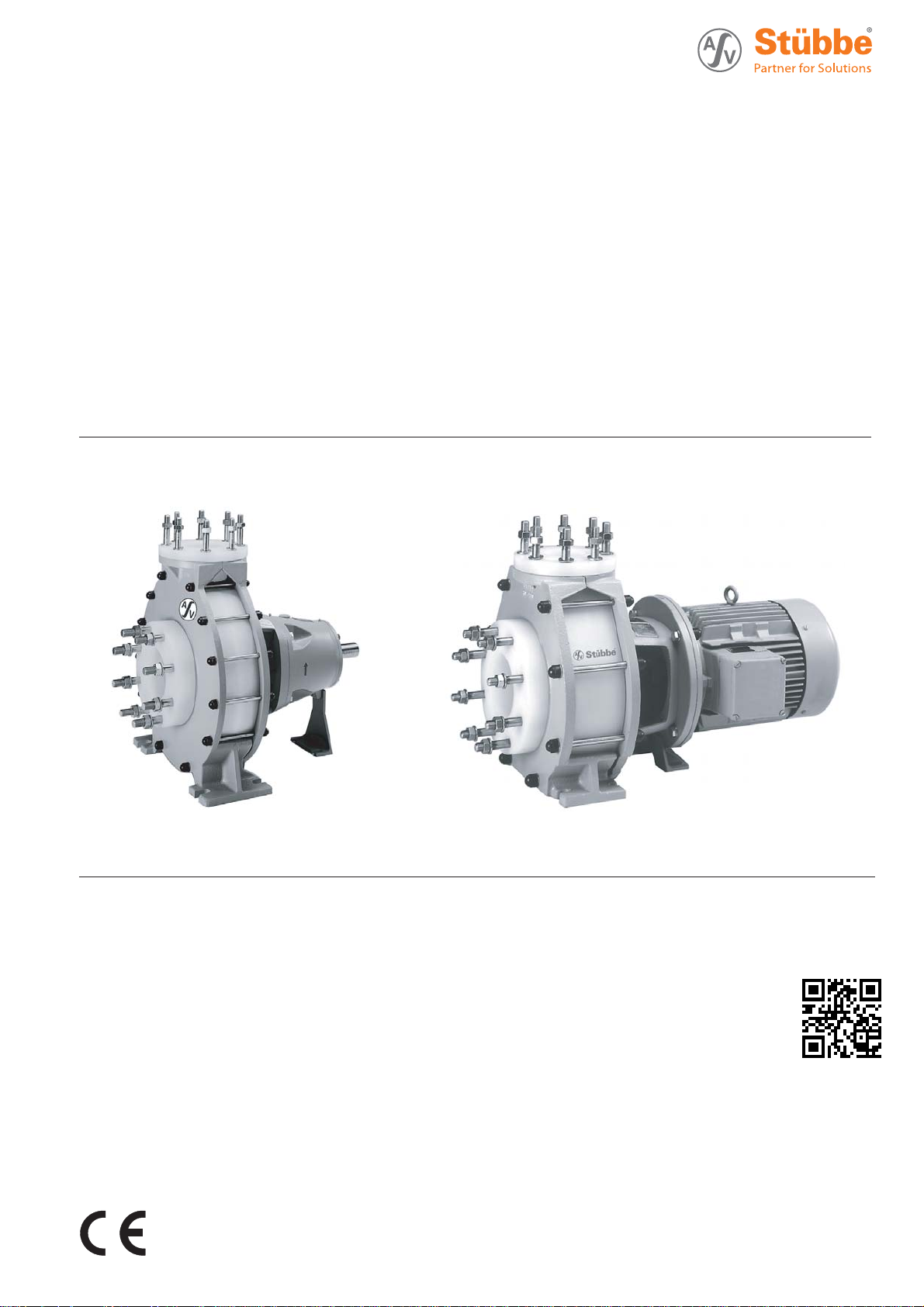
Volute
Centrifugal Pump
Original Operating Manual Series
NM
NMB
NMXH
Version BA-2015.09.18
Print-No. 300 404
TR MA DE Rev002
ASV Stübbe GmbH & Co. KG
Hollwieser Strasse 5
32602 Vlotho
Germany
Phone: +49 (0)5733-799-0
Fax: +49 (0)5733-799-5000
Email: [email protected]
Internet: www.asv-stuebbe.de
We reserve the right to make technical changes.
Read carefully before use.
Save for fu
ture use.
Page 2

Table of contents
Table of contents
1 About this document ............................... 5
1.1 Target groups .......... ....................... 5
1.2 Other applicable documents ................ 5
1.3 Warnings and symbols ....................... 6
2 General safety instructions ....................... 7
2.1 Intended use ................................ .. 7
2.2 General safety instructions ..... ............. 7
2.2.1 Product safety ................................ 7
2.2.2 Operator's obligations . ....................... 8
2.2.3 Obligations of personnel ..................... 8
2.3 Specific hazards .............................. 8
2.3.1 Hazardous pumped liquids .................. 8
2.3.2 Potentially explosive atmospheres .. .. .. .. .. 8
3 Layout and function ...... .......................... 9
3.1 Labels .......................... ............... 9
3.1.1 Type plate ........................... .......... 9
3.1.2 ATEX nameplate ...................... ....... 9
3.2 Description .......................... .......... 9
3.3 Layout ......... ................................ 10
3.4 Shaft seals .......... .......................... 10
3.4.1 Mechanical seals ........ ..................... 10
3.4.2 Auxiliary systems .. . .. .. .. .. .. .. .. .. .. .. .. .. .. 11
4 Transport, Storage and Disposal ................. 12
4.1 Transport .................................. .... 12
4.1.1 Unpacking and inspection upon
delivery ........ ................................ 12
4.1.2 Lifting ........................... ............... 12
4.2 Storage ....... ................................ 13
4.3 Disposal ....... ................................ 13
5 Installation and connection ....................... 14
5.1 Preparing the setup .......................... 14
5.1.1 Check operating conditions .... ............. 14
5.1.2 Preparing the installation site ............... 14
5.1.3 Prepare foundation and surface ............ 14
5.2 Installing with foundation ................ .... 15
5.2.1 Place pump unit on the foundation .. . .. .. .. 15
5.2.2 Attaching pump unit .......................... 15
5.3 Installing motor ..................... .......... 16
5.4 Planning the pipes .............. ............. 16
5.4.1 Specifying supports and flange
connections ... ................................ 16
5.4.2 Specifying nominal widths ................... 16
5.4.3 Specifying pipe lengths ...................... 17
5.4.4 Provide self-priming container .............. 17
5.4.5 Optimizing changes of cross se c tion and
direction ..................................... .. 17
5.4.6 Discharging leaks .......................... .. 17
5.4.7 Providing safety and control devices
(recommended) .................... .......... 17
5.5 Connecting the pipes ................. ....... 18
5.5.1 Keeping the piping clean ................ .... 18
5.5.2 Installing auxiliary pipes .............. ....... 18
5.5.3 Installing suction pipe ........................ 18
5.5.4 Installing the pressure pipe ........ .......... 18
5.5.5 Inspection for stress-free pipe
connections ... ................................ 18
5.6 Electrical connection ......................... 18
5.6.1 Connecting the motor ........................ 18
5.6.2 Checking the direction of rotation . .. .. .. .. .. 18
5.7 Performing the hydrostatic test .............. 18
5.8 Aligning the coupling precisely . ............. 19
5.9 Aligning motor ................................ 19
6Operation............................................ 20
6.1 Preparing for commissioning ................ 20
6.1.1 Checking downtimes ......................... 20
6.1.2 Filling and bleeding ..... ..................... 20
6.1.3 Preparing auxiliary systems (if
present) ....................................... 20
6.1.4 Check direction of rotation ...... ............. 20
6.2 Commissioning ........................... .... 21
6.2.1 Switching on ............. ..................... 21
6.2.2 Switching off .................................. 21
6.3 Shutting down the pump ... .................. 22
6.4 Restoring the pump to service .............. 23
6.5 Operating the stand-by pump ............... 23
7 Maintenance ............... .......................... 24
7.1 Inspections ................................... 24
7.2 Maintenance .. ................................ 24
7.2.1 Maintenance in accordance with maintenance
schedule ................. ..................... 25
7.2.2 Check sealing medium ...................... 25
7.2.3 Cleaning the pump ................. .......... 25
7.3 Dismounting .................................. 26
7.3.1 Preparations for dismounting ................ 26
7.3.2 Disassembly NM NMB ....................... 27
7.3.3 Disassemble NMXH ......................... 27
7.4 Replacement parts and return .............. 27
7.5 Installing .................... .................. 28
7.6 Assembly instruction for shaft protection
sleeve .... ..................................... 28
8 Troubleshooting ..................... ............... 29
9 Appendix ........................... .................. 32
9.1 Replacement parts ........................... 32
9.1.1 Series NM ..................... ............... 32
9.1.2 Series NMB ................................... 34
9.1.3 Series NMXH ............ ..................... 36
9.2 Technical specifications ...................... 38
9.2.1 Ambient conditions ........................... 38
9.2.2 Parameters for auxiliary systems . . .. .. . .. .. 38
9.2.3 Sound pressure level .................... .... 38
2 NM NMB NMXH BA-2015.09.18 300 404
Page 3

9.2.4 Flange tightening torques ................... 38
9.2.5 Tightening torques of casing screws . . ... . .. 38
9.2.6 Gap size ................ ...................... 38
9.2.7 Lubricant ........................... ........... 39
9.3 Declaration of conformity in accordance with
EC machinery directive ...................... 40
Table of contents
300 404 BA-2015.09.18 NM NMB NMXH 3
Page 4

Table of contents
List of figures
Fig. 1 Type plate (example) ...... .................. 9
Fig. 2 ATEX nameplate (example) ................. 9
Fig. 3 Layout ......... ................................ 10
Fig. 4 Attach lifting gear to the pump unit . .. .. .. .. 12
Fig. 5 Attach lifting gear to pump ......... .......... 12
Fig. 6 Installation with foundation .................. 15
Fig. 7 Straight pipe lengths in front and after the
pumps (recommended) ...................... 17
Fig. 8 Checking the coupli ng alignment . .. .. .. .. .. 19
Fig. 9 Checking for lateral and vertical
misalignment ....................... .......... 19
Fig. 10 Checking angular offset . ..................... 19
Fig. 11 Sectional drawing ............................ 33
Fig. 12 Sectional drawing NMB ...................... 35
Fig. 13 Sectional drawing NMXH .................... 37
Fig. 14 Lubricating points with grease nipples . . . ... 39
List of tables
Tab. 1 Other applicable documents, purpose and
where found ........................ .......... 5
Tab. 2 Warnings and symbols ....................... 6
Tab. 3 Quenching - variants and features .......... 11
Tab. 4 Blocking - variants and features ............ 11
Tab. 5 Measures to be taken if the pump is shut
down .......... ................................ 22
Tab. 6 Measures depending on the behavior of the
pumped liquid .............. .................. 22
Tab. 7 Maintenance plan ............................ 25
Tab. 8 Fault/number assignment ................... 29
Tab. 9 Troubleshooting list ................... ....... 31
Tab. 10 Designation of components according to part
numbers ...... ................................ 32
Tab. 11 Designation of components according to part
numbers ...... ................................ 34
Tab. 12 NMXH: Part numbers and component
designations ........................ .......... 36
Tab. 13 Ambient conditions ......... .................. 38
Tab. 14 Blocking liquid pressure and outlet
temperature ......................... .......... 38
Tab. 15 Flange tightening torques ...... ............. 38
Tab. 16 Tightening torques of casing screws .. .. .. .. 38
Tab. 17 Lubricant ............ .......................... 39
Tab. 18 Grease/oil lubricant quantity ................. 39
4 NM NMB NMXH BA-2015.09.18 300 404
Page 5
1 About this document
About this document
This manual
• Is part of the equipment
• Applies to the aforementioned pump series
• Describes safe and appropriate operation during all operating phases
1.1 Target groups
Operating company
• Responsibilities:
– Always keep this manual accessible where the device
is used on the system.
– Ensure that employees read and observe this docu-
ment, particularly the safety instructions and warnings,
and the documents which also apply.
– Observe any additional country-specific rules and reg-
ulations that relate to the system.
Qualified personnel, fitter
• Mechanics qualification:
– Qualified empl oyees with additional trainin g for fitting
the respective pipework.
• Electrical qualification:
– Qualified electrician
• Transport qualification:
– Qualified transport specialist
• Responsibility:
– Read, observe and follow this manual and the other
applicable documents, especially all safety instructions
and warnings.
1.2 Other applicable documents
Document/purpose/
ATEX additional manual (300 364)
• Additional instructions for use in
explosive atmospheres
• http://www.asv-stuebbe.de/
pdf_manuals/300364.pdf
Resistance lists
• Resistance of materials used to
chemicals
• http://www.asv-stuebbe.de/
pdf_resistance/300050.pdf
CE declaration of conformity
• Conformity with standards
Data sheet (technical specifications,
operating conditions, dimensions)
NM
NMB
NMXH
Selfpriming
container
• Pump NM (340 021)
• http://www.asv-stuebbe.de/
pdf_datasheets/340021.pdf
• Pump NMB (340 022)
• http://www.asv-stuebbe.de/
pdf_datasheets/340022.pdf
• Pump NMXH (300 416)
• http://www.asv-stuebbe.de/
pdf_datasheets/300416.pdf
• Self priming container NM,
NMB, NMXH (300 422)
• http://www.asv-stuebbe.de/
pdf_datasheets/300422.pdf
Where
found
(→ 9.3 Declaration of
conformity
in accordance with
EC machinery directive,
Page 40).
Supplier documentation
• Technical documentation for supplier
components (e.g mechanical seal)
Tab. 1 Other applicable documents, purpose
and where found
300 404 BA-2015.09.18 NM NMB NMXH 5
Documentation included
Page 6
About this document
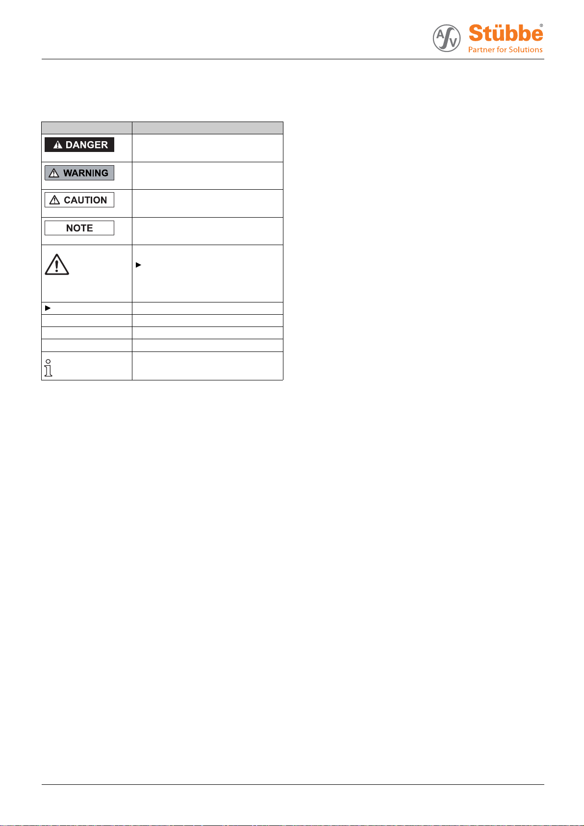
1.3 Warnings and symbols
Symbol
1. , 2. , … Multiple-step instructions
→
Tab. 2 Warnings and symbols
Meaning
• Immediate acute risk
• Death, serious bodily harm
• Potentially acute risk
• Death, serious bodily harm
• Potentially hazardous situation
• Minor injury
• Potentially hazardous situation
• Material damage
Safety warning sign
Take note of all information
highlighted by the safety warning
sign and follow the instructions to
avoid injury or death.
Instruction
Precondition
Cross-reference
Information, advice
6 NM NMB NMXH BA-2015.09.18 300 404
Page 7

2 General safety instructions
General safety instructions
The manufacturer does not accept any liability for any damage caused by disregarding any secti ons of the entire documentation.
2.1 Intended use
• Only use the pump with suitable media (→ resistance lists).
• Do not use pump with solid particles or abra s ive fluids.
If pumps are to be used for solid particles, then agree use
in advance with the manufacturer.
• Do not use pump with combustib le or explosive fluids.
• Adhere to the operatin g limits and size-dependent minimum flow rates.
• Avoid dry running:
Initial damage, such as destruction of bearings, seals and
plastic parts, will occur within a few seconds.
– Make sure the pump is only operated with, and never
without, pumped liquid.
• Avoid cavitation:
– Open suction-side fitting fully and do not use to regulate
flow.
– Do not open the pressure-side fitting beyond the
agreed operating point.
• Avoid overheating:
– Do not operate the pump while the p ressure-side fitting
is closed.
–Noteminimumflow (→ Data sheet).
• Avoid damage to the motor:
– Do not open the pressure-side fitting beyond the
agreed operating point.
– Note the maximum permissible number of times th e
motor can be switched on per hour (→ manufacturer's
specifications).
• Consult the manufacturer about any other use of the pump.
• If pumps are delivered without motors, then final assembly
as a pump assembly must take place in accordance with
the provisions of machinery directive 2006/42/EC.
Prevention of o bvious misuse (examples)
• Observe pump limits of use regarding temperature, pressure, flow and speed (→ Data sheet).
• The power consumption of the pump increases as the the
specific gravity of the pumped fluid increases. Adhere to
the permissible specific gravity in order to eliminate the
possibility that the pump, coupling and motor are overloaded (→ Data sheet).
A lower specific gravity is permissible. Adapt the auxiliary
systems accordingly.
• When conveying fluids containing solids, observe the limit
values for proportions of solid particles and particle size
(→ Data sheet, technical description).
• When using auxiliary plant systems:
– Ensure compatibility of the operating medium with the
product medium.
– Ensure constant supply of the relevant operating
medium.
• Pumps used with water as the pumped liquid must not be
used for food stuffs or drinking water. Use with food or
drinking water must be specified in the data sheet.
• Typeofinstallationshouldonlybeselectedinaccordance
with these operating instructions. For example, the following are not allowed:
– Hanging base plate pumps in the pipe
– Overhead installation
– Installation in the immediate vicinity of extreme heat or
cold sources
– Installation too close to the wall
2.2 General safety instructions
Observe of the following regulations before carrying out
any work.
2.2.1 Product safety
The pump has been built according to state-of-the-art technology and the recognized technical safety regulations. Nevertheless, operation of the pump can still put the life and health
of the user or third parties at risk or damage the pump or other
property.
• Only op erate the pump if it is in perfect technical condition
and only use it as intended, staying aware of safety an d
risks, and in adherence to the instructions in this manual.
• Keep this manual and all other applicable documents complete, legible and accessible to personnel at all times.
• Refrain from any procedures and actions that would pose
a risk to personne l or third parties.
• In the event of any safety-relevant faults, shut down the
pump immediately and have the fault corrected by appropriate personnel.
• In addition to the entire documentation for the product,
comply with statutory or other safety and accident-prevention regulations and the applicable standards and guid elines in the country where the pump is operated.
300 404 BA-2015.09.18 NM NMB NMXH 7
Page 8

General safety instructions
2.2.2 Operator's obligations Safety-conscious operation
• Only ope rate the pump if it is in perfect technical condition
and only use it as intended, staying aware of safety and
risks, and in adherence to the instructions in this manual.
• Ensure that the following safety aspects are observed and
monitored:
– Adherence to intended use
– Statutory or other safety and accident-prevention reg-
ulations
– Safety regulations governing the handling of haz-
ardous substances
– Applicable stand ards and gu idelines in the country
where the pump is operated
– Applicable guidelines of the operator
• Make personal protective equipment available.
Qualified personnel
• Make sure all personnel tasked wi th work on the pump
have read and understood this manual and all other applicable documents, especially the safety, main te nance and
repair information, before they start any work.
• Organize responsibilities, areas of competence and the
supervision of personnel.
• Ensure that all work is carried out by specialist technicians
only:
– Fitting, repair and maintenance work
– Transportation
– Work o n the electrical system
• Make sure that trainee personnel only work on the pump
under supervision of specialist technicians.
Safety equipment
• Provide the following safety equipment a nd verify its functionality:
– For hot, cold and moving parts: pump safety guarding
provided by the customer
– For pumps without capability to run dry: Dry run pro-
tection
– For potential electrostatic charging: provide suitable
grounding
Warranty
• Obtain the manufacturer's approval prior to carrying out
any modifications, repairs or alterations during the warranty
period.
• Only use genuine parts or parts that have been approved
by the manufacturer.
2.2.3 Obligations of personnel
• All directions given on the pump must be followed (and kept
legible), e.g. the arrow indicating the sense of rotation and
the markings for fluid connections.
• Pump, coupling guard and components:
– Do not step on them or use as a climbing aid
– Do not use them to support boards, ramps or beams
– Donotusethemasafixing point for winches or sup-
ports
– Do not use them for storing paper or similar materials
– Do not use hot pump or motor components as a heating
point
– Do not de-ice using gas burners or similar tools
• Do not remove the safety guarding for hot, cold or moving
parts during operation.
• Use personal protective equipment if necessary.
• Only carry out work on the pump while it is not running.
• Before all installation and maintenance work, disconnect the motor from the mains and secure against being
switched back on again.
• Never reach into the suction or discharge flange.
• Following all work on the pump, refit safety devices in
accordance with the instructions and bring into service.
2.3 Specific hazards
2.3.1 Hazardous pumped liquids
• When handling hazardous fluids, observe the safety regulations for the handling of hazardous substances.
• Use personal protective equipment when carrying out any
work on the pump.
• Collect leaking pumped liquid and residues in a safe manner and dispose of in accordance with environmental regulations.
2.3.2 Potentially explosive atmospheres
Observe ATEX additional manual
• Additional instructions for use in explosive atmospheres
• www.asv-stuebbe.de/pdf_manuals/300364.pdf
8 NM NMB NMXH BA-2015.09.18 300 404
Page 9
3 Layout and function
Layout and function
3.1 Labels
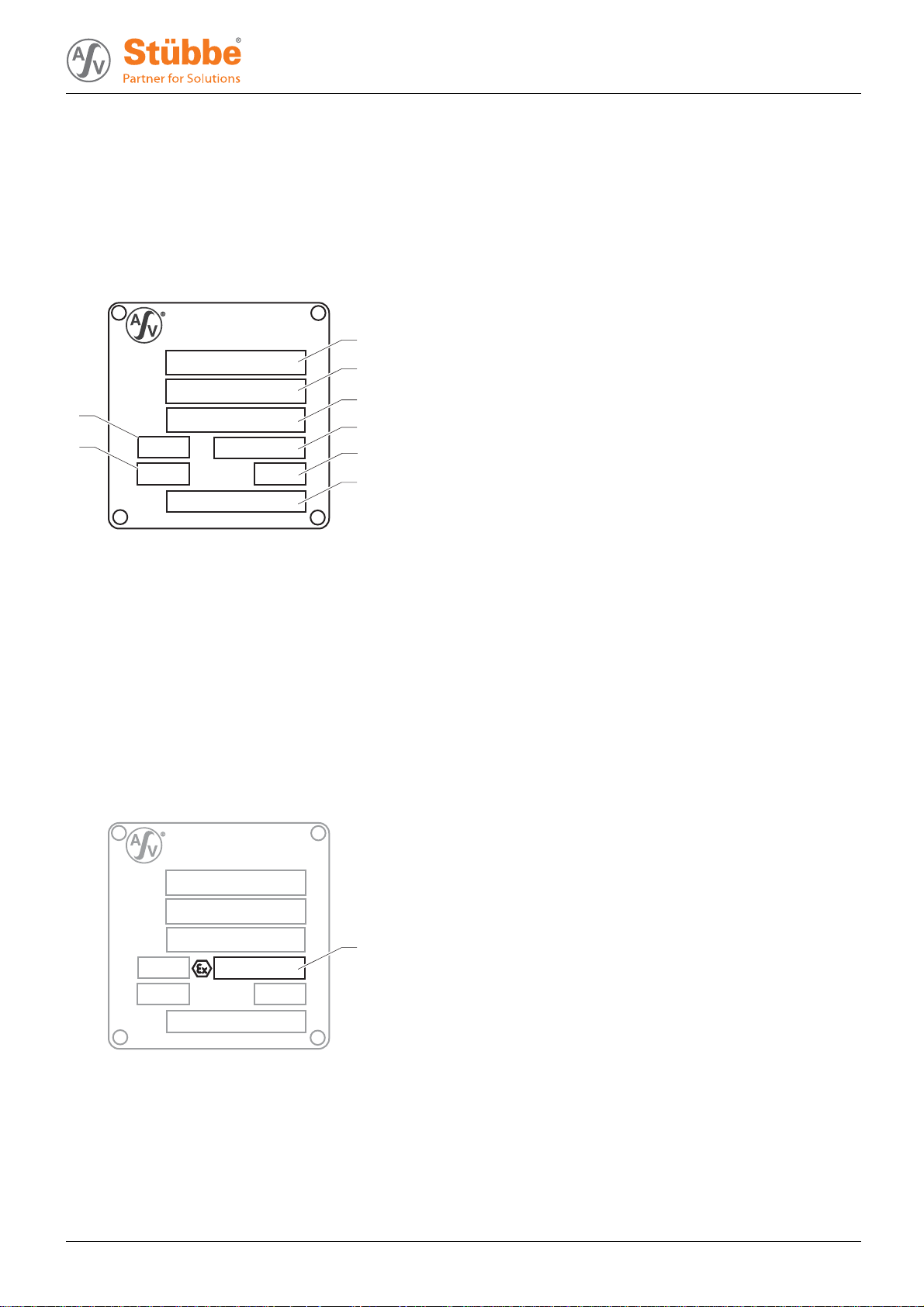
3.1.1 Type plate
ASV Stübbe GmbH & Co. KG
Tel.: +49 (0) 57 33 / 79 9-0
Typ
Fabr. Nr.
8
Werkst.
L ø
7
Q
GLRD
Fig. 1 Type plate (example)
1Pumptype
2 Serial number
3 Housing / sealing material
4–
5 Differential head
6 Shaft seal information
7Flow
8 Impeller diameter [mm]
m
3
/h
H
m
3.2 Description
• NM: Standard pump
– Horizontal, single-stage, non self-priming pump with
single flow volute casing and free shaft end.
– Optionally available complete with coupling and drive
motor, mounted on a base plate.
1
2
3
4
5
6
• NMB: Close coupled pump
– Horizontal, single-stage, non self-priming pump with
single flow volute casing.
–Drivemotorisflang ed on to the pump housing with
wafer type flange (without coupling)
– Torque is transmitted from the drive to the pump by an
extended motor shaft.
• NMXH: Standard pump of modular concept
– Horizontal, single-stage, non self-priming pump with
single flow volute casing and free shaft end.
– Slide-in unit can be dismounted without removing
volute casing and piping.
– Optionally available complete with coupling and drive
motor, mounted on a base plate.
3.1.2 ATEX nameplate
ASV Stübbe GmbH & Co. KG
Tel.: +49 (0) 57 33 / 79 9-0
Typ
Fabr. Nr.
Werkst.
L ø
Q
m
3
/h
H
GLRD
Fig. 2 ATEX nameplate (example)
1 Explosion protection label
1
m
300 404 BA-2015.09.18 NM NMB NMXH 9
Page 10
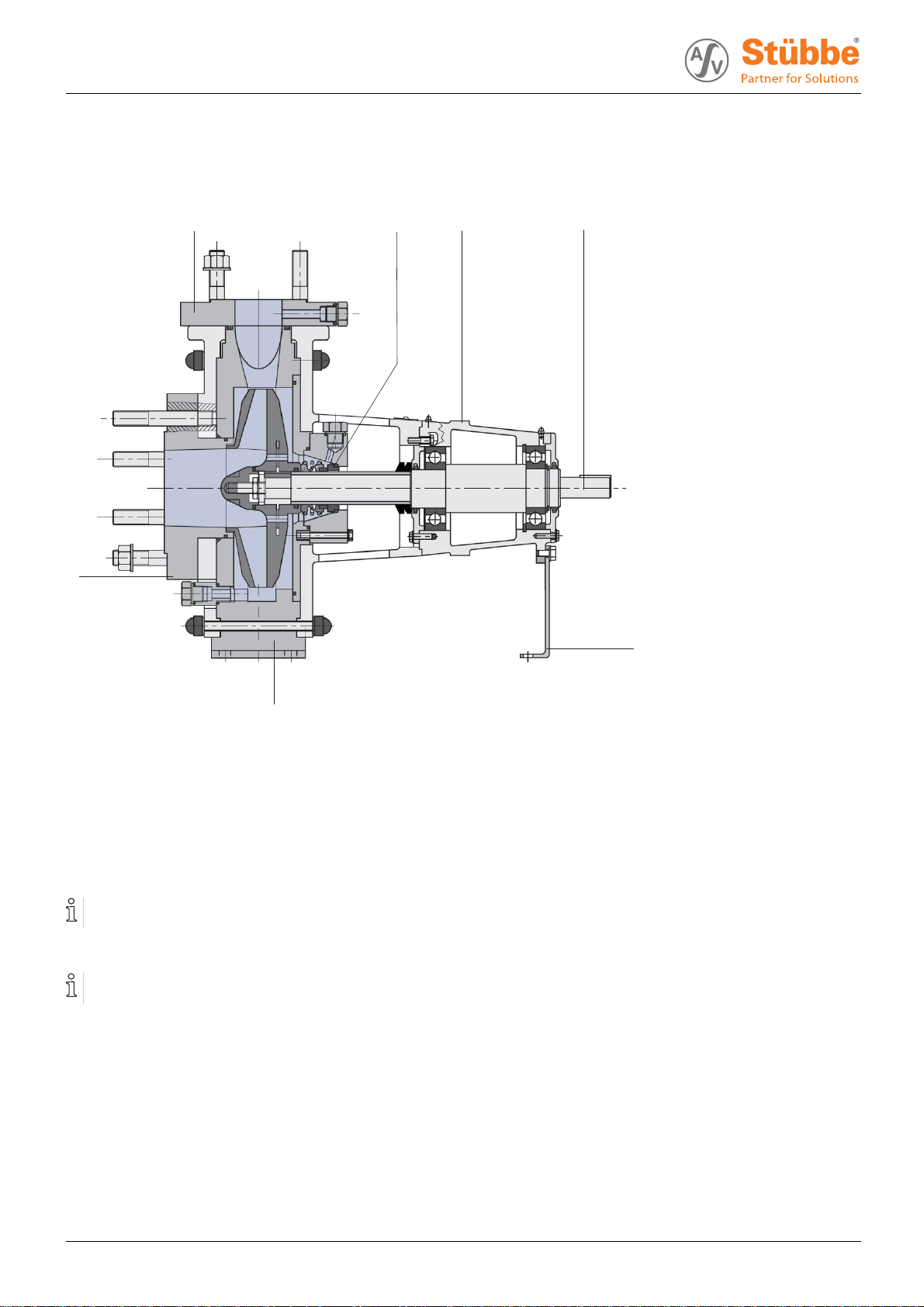
Layout and function
3.3 Layout
1
7
2
3
4
5
6
Fig. 3 Layout
1 Discharge flange
2 Mechanical seal
3 Bearing casing
4Shaft
5 Support foot
6Pumpcasing
3.4 Shaft seals
Only one of the following shaft seals can be used.
3.4.1 Mechanical seals
Mechanical seals have a function-related l eak.
• Single acting mechanical seal
• Single acting, non-balanced mechanical seal
• Double acting mechanical seal
• Double acting, non-balanced mechanical seal
7 Suction branch
10 NM NMB NMXH BA-2015.09.18 300 404
Page 11
3.4.2 Auxiliary systems Sealing systems
Only one of the following sealing systems can be used.
Quenching
When quenchin g, the pressure of the pumped mediu m is
greater than the pressure of the sealing mediu m. The seal
surfaces are lubricated by the pumped medium.
Examples of use:
• Pumped media which reacts chemically with the air
• Prevention of offensive odors
• Cooling of seals
• Protection from icing
Layout and function
Variant
Features of sealing
medium
With open flow • Supplied and drained
continuously
• Unpressurized
In the closed system
• Circulating in a closed
circuit
• Unpressurized
Tab. 3 Quenching - variants and features
Blocking
When blocking, the pressure of the sealing medium is greater
than the pressure of the pumped medium. The seal surfaces
arelubricatedbythesealingmedium.
Examples of use:
• Pumped media which crystallizes or contains solids and
therefore damages the seal in the long-term
• Toxic conveyed media
• Environmentally hazardous conveyed media
Variant
Features of sealing
medium
With open flow • Supplied and drained
continuously
• Impingedwithpressure
In the closed system
• Circulating in a closed
circuit
• Impingedwithpressure
Tab. 4 Blocking - variants and features
300 404 BA-2015.09.18 NM NMB NMXH 11
Page 12

Transport, Storage and Disposal
4 Transport, Storage and Disposal
4.1 Transport
Weight specifications (→ documents for the particular
order).
4.1.1 Unpacking and inspection upon delivery
1. Unpack the pump/pump assembly upon delivery and
inspect it for transport damage.
2. Check com pleteness and accuracy of delivery.
3. Report any transport damage to the manufacturer immediately.
4. Dispose of packaging material according to local regulations.
4.1.2 Lifting
DANGER
Death or limbs crushed as a result transported items
falling over.
Use lifting gear appropriate for the total weight to be transported.
Attach lifting gear in accordance with the following diagrams.
Never attach the lifting gear to the lifting eye of the motor
(other than for securing against knocking over for pump
assemblies with a high center of gravity).
Do not stand under suspended loads.
Fig. 4 Attach lifting gear to the pump unit
Fig. 5 Attach lifting gear to pump
1. Attach lifting gear in accordance with the following diagrams.
2. Lift pump/pump assembly ap propriately.
12 NM NMB NMXH BA-2015.09.18 300 404
Page 13

4.2 Storage
NOTE
Material damage due to inappropriate storage!
Store the pump properly.
1. Seal all openings with blind flanges, blind plugs or plastic
covers.
2. Make sure the storage room meets the following conditions:
–Dry
– Frost-free
– Vibration-free
–UVprotected
3. Turnthepumptwiceamonth.
4. Make sure the shaft and bearing change their rotational
position in the process.
4.3 Disposal
Transport, Storage and Disposal
Plastic parts can be contaminated by poisonous or radioactive pumped liquids to such an extent that cleaning will be
insufficient.
WARNING
Risk of poisoning and environmental damage by the
pumped liquid or oil!
Use p ersonal p rotective equipment when carrying out any
work on the pump.
Prior to the disposal of the pump:
– Collect and dispose of any escaping pumped l iquid or
oil in accordance with local regulations.
– Neutralize residues of pumped liquid in the pump.
Remove the plastic parts and dispose of them in accordance with local regulations.
Dispose of the pump in accordance with local regulations.
300 404 BA-2015.09.18 NM NMB NMXH 13
Page 14

Installation and connection
5 Installation and connection
For pumps in potentially explosive atmospheres (→ ATE X
additional manual).
NOTE
Material damage due to distortion or passage of electrical
current in the bearing!
Do not make a ny structural modifications to the pump
assembly or pump casing.
Do not carry out any welding work on the pump assembly
or pump casing.
NOTE
Material damage caused by dirt!
Do not remove the transport seals until immediately before
settingupthepump.
Do not remove any covers or transport and sealing covers
until immediately before connecting the p ipes to the pump.
5.1 Preparing the setup
5.1.1 Check operating conditions
Ensure the required operating conditions are met:
– Resistance of body and seal material to the mediu m
(→ resistance lists).
– Required ambient conditions
(→ 9.2.1 A mbient conditions, P age 38).
5.1.3 Prepare foundation and surface
Aids, tools, materials:
–Steelshims
– Spirit level
Installation options:
– With concrete foundation
– With steel foundation frames
– Without foundation
1. Ensure the foundation and surface meet the following con ditions:
– Level and horizontal
– Clean (no oil, dust or other impurities)
– Capable of bearing the weight of the pump assembly
and all operating forces
– Stability of the pump ensured
– With concrete found ation: Normal concrete of strength
class X0 in accordance with DIN EN 206
2. Clean pump sump carefully.
5.1.2 Preparing the installation site
Ensure the installa tion site meets the followin g conditions:
– Pump is freely accessible from all sides
–Sufficient space for the installation/removal of the pipes
and for maintenance and repair work, especially for the
removal a nd installation of the pump and the motor
– Pump not exposed to external vibrations (damage to
bearings)
– No corrosive exposure
– Frost protection
14 NM NMB NMXH BA-2015.09.18 300 404
Page 15

Installation and connection
5.2 Installing with foundation
NOTE
Material damage due to distortion of base plate.
Position the base plate as follows on the foundation and
attach.
5.2.1 Place pump unit on the foundation
Aids, tools, materials:
– Anchor bolts
– Steel shims
– Mortar casting compound, no shrinkage
– Spirit level
1. Lifting the pump unit (→ 4.1 Transport, Page 12).
2. Hook anchor bolts in the mounting holes on the base plate
from below.
Observe manufacturers information when using the fixing
material.
3. Position the pump unit on the foundation. When doing so
lower the anchor bolts into the prepared anchoring holes.
5.2.2 Attaching pump unit
Filling the base plate with mortar casting compound
improves dampening properties.
1. Fill the anchoring holes with mortar casting compound.
2. When the mortar c asting compound has set, bolt the base
plate at three points to the specified tigh tening torque.
3. Before tightening the remaining bolts, arrange shims next
to every bolt to even out any irregularities in the mounting
surface.
32 1 2
Fig. 6 Installation with foundation
4. Align the pump for height and system dimensions using
steel shims as follows:
– Arrange steel shims (2) to the left and right of each
anchor bolt (1).
– If the distance between the anchoring holes is
> 750 mm, then arrange additi onal steel shims (3) on
each side of the base plate in the center.
5. Ensure that the base plate lies flat against steel shims.
6. Check the permissible height deviation (1 mm/m) using a
mechanical spirit level in a longitudinal and a transverse
direction
7. Repeat the procedure until the base plate is correctly
aligned.
300 404 BA-2015.09.18 NM NMB NMXH 15
Page 16

Installation and connection
5.3 Installing motor
Only necessary if the pump unit is firstassembledonsite.
NOTE
Material damage through bangs and knocks!
Do not tilt the coupling halves when slipping them on.
Do not bang and knock pump components.
1. Smear a very thin coat of molybdenum disulfide (e.g.
Molykote) on the shaft ends of the pump and motor.
2. Insert key.
3. Without mounting rig: Remove rubber buffers and heat
coupling halves to approx. 100 °C.
4. Slideonthepump-sideandmotor-sidecouplinghalves
until the shaft end is flush with the coupling hub. When
doing so, make sure the prescribed distance between the
coupling halves is maintaine d (→ O t her applicable documents, coupling installation instructions).
5. Tighten the threaded pins on both coupling halves.
6. Align the motor shaft en d using appropriate shims on the
motor wi th the height of the pump shaft end.
7. Screw in motor bolts, but do not tighten yet (→ 5.9 Aligning
motor, Page 19).
5.4 Planning the pipes
Water hammers may damage the pump or the system.
Plan the pipes and fittings as far as possible to prevent
water hammers occurring.
5.4.1 Specifying supports and flan ge conne ctions
NOTE
Material damage due to excessive forces and torques on
the pump.
Ensure pipes are connected not under tension.
1. Support pipes in front of the pump.
2. Ensure the pipe supports have permanent low-friction
properties and do not seize up due to corrosion.
5.4.2 Specifying nominal widths
Keep the flow resistance in the pipes as low as possible.
1. Ensure nominal suction pipe width is not smaller than the
nominal suction flange width.
–Avoidflow velocities > 2 m/s.
– Recommended flow velocity < 1 m/s
–Maximumflow velocity = 9 m/s
2. Ensure the nominal pressure line width is not smaller than
the nominal pressure flange width.
–Avoidflow velocities in plastic pipes of more than 3 m/s.
– Recommended flow velocity < 3 m/s
–Maximumflow velocity = 12 m/s
– Install a vent valve, check valve and pressure gauge in
pressure line just behind the disch arge flange.
16 NM NMB NMXH BA-2015.09.18 300 404
Page 17

Installation and connection
5.4.3 Specifying pipe lengths
D
C
A
Fig. 7 Straight pipe lengths in front and after the
pumps (recommended)
A>5xDNs
BDNs
CDNd
D>5xDNd
Observe recommended minimum values when instal ling
the pump.
Suction side: Shorter lengths are possible, but may limit
hydraulic performance data.
Pressure side: Shorter lengths are possible, but may result
in increased noise development.
5.4.4 Provide self-priming container
Aself-primingcontainercanbeusedtomakethepump
self-priming.
1. Select container volumes according to the size of the
pump.
2. Clean containers carefully prior to commissioning or initial
filling.
5.4.5 Optimizing changes of cross section and
direction
1. Avoid radii of curvature of less th an 1.5 times the n
pipe diameter.
2. Avoid abrupt changes of cross-section along the piping.
B
ominal
5.4.6 Discharging leaks
WARNING
Risk of injury and poisoning due to hazardous pumped
liquids!
Safely collect any leaking pumped liquid, then discharge
and dispose of it in accordance with environmental regulations.
1. Provide equipment for collecting and discharging leaking
liquids.
2. Ensure the free discharge of leaking liquids.
5.4.7 Providing safety and control devices
(recommended)
Avoid contamination
1. Install filters in the suction pipe.
2. Install a differential pressure gauge with contact manometer to monitor contamination.
Avoid reverse running
1. Ensure that the medium does not flow back after switchingoffthepumpbyusinganon-returnvalvebetweendischarge flange and stop valve.
2. In order to enable venting, include vent connection
between discharge flanges and non-return valve.
Make provisions for isolating and shutting off the pipes
For maintenance and repair work.
Provide shut-off devices in the suction pipe and pressure
line.
Allow measurements of the operating conditions
1. Provide pressure gauge in the suction pipe and pressure
line for pressure measurement.
2. Provide motorside load monitors (over and underload).
3. Provide pressure measurement on the pump side.
Providing dry run protection
In order to protect the pump from dry running and resulting
damage
– Provide dry run protection
– e.g. ASV PTM pressure and temperature monitoring
sensor
Provide an overpressure protection
Overpressure protection is required for operation in explosive areas (→ ATEX additi onal manual).
Provide an overpressure protection.
300 404 BA-2015.09.18 NM NMB NMXH 17
Page 18

Installation and connection
5.5 Connecting the pipes
NOTE
Material damage due to excessive forces and torques on
the pump.
Ensure pipe connection without tension.
5.5.1 Keeping the piping clean
NOTE
Material damage due to impurities in the pump!
Make sure no impurities can enter the pump.
1. Clean all piping parts and fittings prior to assembly.
2. Flush all pipes carefully with neutral medi um.
3. Ensure no flan ge seals protrude inwards.
4. Remove any blind flanges, pl ugs, protective foils and/o r
protective paint from the flanges.
5.5.2 Installing auxiliary pipes
Observe manufacturer information for any auxiliary systems present.
1. Connect the auxiliary pipes to the auxiliary connections so
that they are stress-free and do not leak.
2. Avoid formation of air pockets: Run the pipes with a continuous slope up to the pump.
5.6 Electrical connection
DANGER
Risk of death due to electric shock!
All electrical work must be carried out by qualified electricians only.
Before all work on the electrical system, disconnect the
motor from the mains and secure against being switched
back on again.
5.6.1 Connecting the motor
Follow the instructions of the motor manufacture r.
1. Connect the motor according to the connection diagram.
2. Make sure no danger arises due to electric power.
3. Install an EMERGENCY STOP switch.
5.6.2 Checking the direction of rotation
Only possible when starting up (→ 6.2 C ommissioning,
Page 21).
5.7 Performing the hydrostatic test
Only necessary if the entire system needs to be tested
under pressure.
5.5.3 Installing suction pipe
1. Remove the transport and sealing covers from the pump.
2. Fit suction pipe stress-free and sealed. (→ 9.2.4 Flange
tightening torques, Page 38).
3. Ensure no seals protrude inwards.
4. For the suction process: Install foot valve in the suction
pipe in order to prevent the pump and suction pipe from
dry running when pump is not running.
5.5.4 Installing the pressure pipe
1. Remove the transport and sealing covers from the pump.
2. Fit pressure line stress-free and sealed. (→ 9.2.4 Flange
tightening torques, Page 38).
3. Ensure no seals protrude inwards.
5.5.5 Inspection for stress-free pipe connections
Piping installed and cooled down
1. Disconnect the pipe connecting flanges from
2. Check whether the pipes can be moved freely in all directions within the expected range of expansion:
– Nominal width < 150 mm: by hand
– Nominal width > 150 mm: with a small lever
3. Make sure the flange surfaces are paral lel.
4. Reconnect the pipe connecting
5. If present, check support foot for tension.
flanges to the pump.
the pump.
NOTE
Material damage due to bursting of pump casing.
Testing pressure must not exceed the permissible pump
pressure (→ documents for the p articular order).
Make sure the tes ting pressure does not exceed the permissible pump pressure.
– If necessary, do not perform pressure test on the pump.
18 NM NMB NMXH BA-2015.09.18 300 404
Page 19

Installation and connection
5.8 Aligning the coupling precisely
Only necessary for versions with coupling.
DANGER
Danger to life from rotating parts.
For all installation and maintenance work, disconnect the
motor from the mains and secure aga inst being switched
back on again.
NOTE
Material damage due to incorrect alignment of coupling.
Align the motor exactly to the pump if there i s any vertical,
lateral or angular misalignment.
For more detailed information and for special couplings:
(→ Manufacturer information).
Checking the coupling alignment
Aids, tools, materials:
– Feeler gauge
– Straight edge
– Dial gauge (possibly for couplings with spacer piece)
– Other appropriate tools, e.g. laser alignment device
A
3. Check the gap size with feeler gauge (2):
– Permitted gap dimension (→ 9.2.6 Gap size,
Page 38).
– Measure size of the gap between the coupling halves
using feeler gauge (A).
– If the gap size is not permitted, align the motor
(→ 5.9 Aligning motor, Page 19).
Fig. 9 Checking for lateral and vertical misalignment
4. Check for any lateral or vertical misalignment using the dial
gauge:
– Complete measurement as shown.
– Align the motor if there is any lateral or vertical mis-
alignment (→ 5.9 Aligning motor, Page 19).
Permissible axial or radial deviation, measured on coupling front or circumference: < 0.05 mm
1
2
Fig. 8 Checking the coupling alignment
1. Measure the coupling in two planes on the circumference
at an angle of 90°.
2. Check the light gap on the outer circumference with straight
edge (1):
– Lay straight edge across both coupling halves.
– Align the motor if there is a visible gap on the outer
circumference (→ 5.9 Aligning motor, Page 19).
Fig. 10 Checking angular offset
5. Checking for an gular displacement
– Complete measurement as shown.
– If there is any angular displacement: align the motor.
Permissible angular offset < 0.03 mm
5.9 Aligning motor
1. Align the motor so that the coupling halves align exactly, if
necessary place alignment plates underneath.
2. Check alignment.
3. Repeat alignment procedure if there is still a vertical misalignment.
4. After that, tighten the motor bolts.
300 404 BA-2015.09.18 NM NMB NMXH 19
Page 20

Operation
6Operation
For pumps in potentially explosive atmospheres (→ ATE X
additional manual)
6.1 Preparing for commissioning
6.1.1 Checking downtimes
Check downtimes (→ 6.4 Restoring the pump to service,
Page 23).
6.1.2 Filling and bleeding
WARNING
Risk of injury and poisoning due to hazardous fluid!
Use prote ctive equipment for any work on the pump.
Safely collect the fluid and dispose of it in accordance with
environmental regulations.
NOTE
Material damage as a result of dry running
Make sure the pump is filled properly.
1. If present, fill and vent self-priming container with fluid.
2. Open the suction-side fitting.
3. Open the p ressure-side fitting.
4. Fill pump and suction pipe with fluid.
5. Verify that no pi pe connections are leaking.
6.1.4 Check direction of rotation
DANGER
Danger to life from rotating parts.
Use personal protective equipment when carrying out any
work on the pump.
Maintain an adequate distance from rotating parts.
NOTE
Material damage as a result of dry running.
Make sure the pump is filled properly.
1. Switch on motor for max. of 2 seconds and switch off again
immediately.
2. Check whether the sense of rotation of the motor matches
the direction of rotation on the fan.
3. If the sense of rota tion is different: change over the two
phases (→ 5.6 Electrical connection, Page 18).
6.1.3 Preparing auxiliary systems (if present)
The manufacturer accepts no liability for damage arising due to the installation or use of a third party or
non-approved auxiliary system.
Sealing systems
1. Ensure that the sealing medium is appropriate to mix with
the pumped medium.
2. Ascertain the sealing system
(→ documents for the particular order)
3. Install the sealing system (→ manufacturer information).
4. Ensure the necessary parameters for the sealing system
(→ manufacturer information).
5. Ensure that the container pressure is not lower than that
permitted for blocking pressure systems (→ manufacturer
information).
20 NM NMB NMXH BA-2015.09.18 300 404
Page 21

Operation
6.2 Commissioning
6.2.1 Switching on
Pump set up and connected properly
Motor set up and connected properly
Align motor precisely to the pump
All connections stress-free and sealed
All safety equipment installed and tested for functionality
Pump prepared, filled and vented correctly
DANGER
Risk of injury from running pump!
Do not touch the running pump.
Ensure that the coupling guard is attached.
Do not c arry out any work on the running pump.
Allow the pump to coo l down completely before starting any
work.
DANGER
Risk of injury and poisoning due to pumped liquid spraying out!
Use p ersonal p rotective equipment when carrying out any
work on the pump.
5. Make sure temperature change is smaller than 5 K/min for
pumps with hot fluids.
6. After the initial stress due to the pressure and operating
temperature, check that the pump is not leaking.
6.2.2 Switching off
Pressure-side fi tting c losed (recommended)
WARNING
Risk of injury due to hot pump parts!
Use p ersonal p rotective equipment when carrying out any
work on the pump.
1. Switch off motor.
2. Check all connecting bolts and tighten if necessary (only
after initial commissioning).
NOTE
Risk of cavitation if suction flow is restricted!
Open the suction-side fitting and do not use to regulate the
flow.
Do not open the pressure-side fitting beyond the operating
point.
NOTE
Material damage due to o verheating.
Do not operate the pump for long periods with the pressureside fitting closed.
Observe minimum flow (→ documents for the particular
order).
NOTE
Material damage as a result of dry running
Make sure the pump is filled properly.
1. Open the suction-side fitting.
2. Close pressure-side fitting
3. Switch on the motor and check it for smooth running.
4. Once the motor has reached its nominal speed, open
the pressure-side fitting slowly until the operating point is
reached.
300 404 BA-2015.09.18 NM NMB NMXH 21
Page 22

Operation
6.3 Shutting down the pump
DANGER
Risk of injury from running pump!
Do not touch the running pump.
Do not carry out any work on the running pump.
Before all installation and maintenance w ork, disconnect the motor from the mains and secure against being
switched back on again.
DANGER
Risk of electrocution!
All electrical work must be carried out by qualified electricians only.
Before all work on the electrical system, disconnect the
motor from the mains and secure against being switched
back on again.
WARNING
Risk of injury and poisoning due to hazardous fluid!
Use prote ctive equipment for any work on the pump.
Collect lea king liquid safely and dispose of fitting in accordance with local regulations.
Take the following measures whenever the pump is shut
down:
Pump is Action
shut down
…emptied
…dismounted
…put into
storage
Tab. 5 Measures to be taken if the pump is shut down
Behavior of the
pumped liquid
Crystallized or
polymerized,
solids
sedimenting
Solidifying/
freezing,
non-corrosive
Solidifying/
freezing,
corrosive
Remains liquid,
non-corrosive
Remains liquid,
corrosive
Tab. 6 Measures depending on the behavior
of the pumped liquid
Take measures appropriate for
the fluid (→ Table 6 Measures
depending on the behavior of
the pumped liquid, Page 22).
Close suction and pressure-side
fitting.
Isolate the motor from its power
supply and secure it against
unauthorized switch-on.
Note measures for storage.
Duration of shutdown (depending
on process)
Short
Flush the
pump.
Heat up or
empty the
pump and
containers.
Heat up or
empty the
pump and
containers.
––
–
Long
Flush the
pump.
Empty the
pump and
containers.
Empty the
pump and
containers.
Empty the
pump and
containers.
22 NM NMB NMXH BA-2015.09.18 300 404
Page 23

6.4 Restoring the pump to service
1. Complete all steps as for commissioning
(→ 6.2 Commissi oni ng, Page 21).
2. If the pump is shut down for over 1 year, replace elastomer
seals (O-rings, shaft sealing rings).
6.5 Operating the stand-by pump
Stand-by pump filled and bled
Operate the stand-by pump at least once a week.
1. Fully open the suction-side fitting.
2. Open pressure-side fitting far enough so that the stand-by
pump operating temperature is achieved and heating is
even (→ 6.2.1 Switching on, Page 21).
Operation
300 404 BA-2015.09.18 NM NMB NMXH 23
Page 24

Maintenance
7 Maintenance
For pumps in potentially explosive atmospheres (→ ATE X
additional manual).
Trained service technicians are available for fitting and
repair work. Submit evidence of conveyed medium on
request ( DIN safety data sh eet or safety certificate).
7.1 Inspections
The inspection intervals depend on the operational strain
on the pump.
DANGER
Risk of injury due to running pump!
Do not touch the running pump.
Do not carry out any work on the running pump.
WARNING
Risk of injury and poisoning due to hazardous pumped
liquids!
Use personal protective equipment when carrying out any
work on the pump.
1. Check at appropriate intervals:
– Adherence to the minimum flow rate
– Normal operating conditions unchanged
– Alignment of coupling and condition of elastic elements
2. For troub le-free operation, always ensure the following:
– No dry running
–Noleaks
–Nocavitation
– Suction side open gate valves
– Free and clean filters
–Sufficient pump inlet pressure
– No unusual running noises or vibrations
– No parting of magnetic coupling
7.2 Maintenance
DANGER
Risk of injury from runn ing pump !
Do not touch the running pump.
Do not carry out any work on the running pump.
For all installation and maintenance work, disconnect the
motor from t he mains and lock.
DANGER
Risk of electrocution!
All electrical work must be carried out by qualified electricians only.
WARNING
Risk of injury and poisoning due to hazardous or hot fluid!
Use prote ctive equipment for any work on the pump.
Allow the pump to cool down completely before commencing any work.
Make sure the pump is unpressurized.
Empty the pump, safely collect the pumped liquid and
dispose of it in accordance with environmental rules and
requirements.
24 NM NMB NMXH BA-2015.09.18 300 404
Page 25

7.2.1 Maintenance in accordance with main-
tenance schedule
Perform maintenance work in accordance with the maintenance schedule.
Designation Interval Maintenance
Pump assembly daily
Self priming container (if present)
Sealing medium
Undoable screwed connections weekly
Pump unit as required
Impeller
Bearing bushes
O-rings
Roller bearing
Mechanical seals
Elastic intermediate ring coupling
Roller bearing
Tab. 7 Maintenance plan
daily
daily
quarterly
after 2,000 operating hours
after 4,000 operating hours
years at t he latest
after 5,000 operating hours
after 12,000 operating hours
not la ter than after 18 m onths
Maintenance
Check for increased noise development.
Check for vibration.
Pay attention to increased current consumption
of the motor.
Check that the anchor bolts are correctly
seated.
Check for oxidation.
Check for leakin g pumped liquid.
Replace defective components immediately in
the event of leakage.
– Mechanical seal (→ other applicable
documents).
Check filling level.
Check (→ 7.2.2 Check sealing medium,
Page 25).
Check for tight fitting.
Cleaning (→ 7.2.3 Cleaning the pump,
Page 25).
Dismount the pump (→ 7.3 Dismounting,
Page 26).
– Check comp one nts for wear and damage
– Clean or replace impeller
– Replace worn components
Regrease (→ 9.2.7 Lubricant, Page 39).
Replace (→ 7.3 Dismounting, Page 26).
Replace.
Replace (→ 7.3 Dismounting, Page 26).
7.2.2 Check sealing medium
Only for version with quench.
7.2.3 Cleaning the pump
NOTE
1. Check filling level of sealing medium.
2. After 4000 operating hours or if the maximum filling level is
reached, replace sealing medium:
– Empty seal chamber and collect sealing medium safely
when doing so.
– Fill sealing chamber with sealing medium.
300 404 BA-2015.09.18 NM NMB NMXH 25
High water pressure or spray water can damage bearings!
Do not clean bearing areas with a water or steam jet.
Clean large-scale grime from the pump.
Page 26

Maintenance
7.3 Dismounting
DANGER
Risk of injury due to running pump!
Do not touch the running pump.
Do not carry out any work on the running pump.
Before all installation and maintenance w ork, disconnect the motor from the mains and secure against being
switched back on again.
DANGER
Risk of electrocution!
All electrical work must be carried out by qualified electricians only.
Before all work on the electrical system, disconnect the
motor from the mains and secure against being switched
back on again.
WARNING
Risk of injury and poisoning due to hazardous or hot fluid!
Use personal protective equipment when carrying out any
work on the pump.
Allow the pump to cool completely before commenc ing any
work.
Make sure the pump is unpressurized.
Empty the pump, safely collect the pumped liquid and
dispose of it in accordance with environmental rules and
requirements.
NOTE
Material damage due to incorrect dismounting/installation
of the pump.
Only specialist mechanics should complete dismounting/
installation work.
7.3.1 Preparations for dismounting
Pump is depressurised
Pump completely empty, flushed and decontaminated
Electrical connections disconnected and motor secured
against switch-on
Pump cooled down
Coupling guard removed
For a coupling with spacer piece: remove distance piece
Manometer lines, manome te r and fixtures dismounted
NOTE
Material damage, fragile components.
Dismount ceramic parts of the plain bearing with care, do
not hit or knock.
1. Dismantle the pipes on the suction and pressure side.
2. Remove pump from the system.
3. When dismounting, observe the following:
– Mark the precise orientation and position of all compo-
nents before dismounting them.
– Dismount c omponents concentrically without canting .
– Dismount pump (→ sectional drawing).
WARNING
Risk of injur y due to heavy components!
Pay attention to the component weight. Lift and transport
heavy components using suitable lifting gear.
Set down components safely and secure them against
overturning or rolling away.
WARNING
Risk of injury during disassembly!
Secure the pressure-side gate valve against accidental
opening.
Depressurize the blocking pressure system, if available.
Wear protective gloves, components can be very sharpedged due to wear or damage.
Remove spring-loaded components carefully (e.g.
mechanical seal, tensioned bearing, valves etc.), as components can be ejected by the spring tension.
Observe the manufacturer's specifications (e.g. for the
motor, coupling, mechanical seal, blocking pressure system, cardan sh aft, drives, belt drive etc.).
26 NM NMB NMXH BA-2015.09.18 300 404
Page 27

Maintenance
7.3.2 Disassembly NM NMB
Impeller fastening: Clockwise thread.
Shaft protection sleeves with locking pin can be pulled off
the shaft by hand.
Shaft protection sleeves without locking pin are made of
artificial carbon/ceramic and are glued with single component glue Sicomet 8400. Shaft protection sleeves made of
artificial carbon/ceramic cannot be disassembled without
breakage.
WARNING
Risk of injury due to shattering ceramic parts
Wear protective equipment
Disassemble ceramic parts carefully.
NOTE
Material damage, fragile components.
Do not hit or knock plastic or ceramic Plastic/ceramic is
sensitive to im pact and will crack easily.
1. Remove protective cap (580.1).
2. Unscrew hexagon nut (920.1).
3. Remove washers (554.3).
4. Unscrew stud bolts (902.1).
5. Remove reinforced casing (155.1) from housing cover
(161.1).
6. Undo impeller mounting (92 0.4, 550.1, 934.1).
Shaft protection sleeves with locking pin
1. Remove the impeller (230.1) from the shaft (210.1).
2. Remove the mechanical seal (433.1) from the shaft protection sleeve (→ other applicable documents, supplier documentation).
3. Remove shaft protection sleeve.
7.3.3 Disassemble NMXH
1. Unscrew hexagon head bolt (901.7).
2. Remove washers (554.11).
3. Remove spring rings (934.7).
4. Pull out impeller unit from the back of the volute casing.
5. Unscrew impeller cap (260).
6. Undo nut (922).
7. Remove spring ring (934.6).
8. Carefully remove the ceramic stationary seal ring (475.1)
from the shaft (230).
9. Remove mechanical seal (472.1) from the shaft.
10. Pull out shaft protection sleeve (523).
11. Undo the screws (914.4).
12. Remove volute casing cover (161) together with
– the mechanical seal bracke t (487)
– Support ring for sealing lid (471.2)
– Sealing lid (471.1)
– Locking pin (485)
– Spring (477.1).
7.4 Replacement parts and return
1. Have the following information ready to hand when ordering spare parts
–Devicetype
– ID number
– Nominal pressure and diameter
– Connection and gasket material
2. Please complete and enclose the document of compliance
for returns
(→ www.asv-stuebbe.de/pdf_DOC/300358.pdf).
Shaft protection sleeves without locking pin
1. Remove the impeller (230.1) with shaft protection sleeve
(524.1) and mechanical seal (433.1) from the pump sha ft
(210.1).
2. Remove the liquid s pl ash ring (507.1) from the shaft protection sleeve (524.1).
3. Remove mechanical seal (433.1) from the shaft protection
sleeve (524.1). (→ other applicable documents, supplier
documentation)
4. Carefully remove shaft protection sleeve (524.1) from the
shaft (210.1) by knocking gently with a hammer.
5. Remove all glue residue from the surface of the shaft using
commercially available “thinner”.
300 404 BA-2015.09.18 NM NMB NMXH 27
Page 28

Maintenance
7.5 Installing
Install components concentrically and without tilting in
accordance with the markings applied.
Apply graphite paste to metallic connections prior to
assembly.
WARNING
Risk of injur y due to heavy components!
Pay attention to the component weight. Lift and transport
heavy components using suitable lifting gear.
Set down components safely and secure them against
overturning or rolling away.
WARNING
Risk of injury during assembly!
Install spring-loaded components carefully (e.g. mechanical seal, tensioned bearing, valves etc.), as components
can be ejected by the spring tension.
Observe the manufacturer's specifications (e.g. for the
motor, coupling, mechanical seal, blocking pressure system, cardan sh aft, drives, belt drive etc.).
NOTE
Material damage due to incorrect dismounting/installation
of the pump.
Only specialist me chanics should com plete dismounting/
installation work.
1. When installing please observe:
– Replace worn parts with genuine spare parts.
– Replace seals, inserting them in such a way that they
are unable to rotate.
– Do not apply synthetic or mineral oil, grease or cleaning
agents to elastomer components.
– Adhere to the prescribed tightening
torques.(→ 9.2.5 Tightening torques of casing screws,
Page 38).
– Shaft protecti on sleeve without locking pin
(→ 7.6 Assembly instruction for shaft protection
sleeve, Page 28).
2. Installing the pump:
– in reverse order to the dismounting
(→ 7.3 Dismounting, Page 26).
– → sectional drawing
3. Installing the pump in the system
7.6 Assembly instruction for shaft
protection sleeve
1. Apply a thin coat of Sicomet to the shaft.
– Observe manufacturer safety data sheet.
2. Push on shaft protection sleeve (524.1) immediately with
inner bevel facing the shaft (210.1).
– Sicomet drying time app rox. 30 s.
NOTE
Material damage due to unsuitable components!
Always replace lost or damaged screws with screws of the
same strength where required (→ 9.2.5 Tightening torques
of casing screws, Page 38).
Only replace sea ls with seals of the same material.
NOTE
Material damage, fragile components
Mount ceramic parts of the plain bearing with care, do not
hit or knock.
28 NM NMB NMXH BA-2015.09.18 300 404
Page 29

8 Troubleshooting
For pumps in potentially explosive atmospheres (→ ATE X
additional manual).
If faults occur which are not specified in the following table or
cannot be traced back to the specified causes, please c onsult
the manufacturer.
Possible faults are identified by a fault number in the table
below. This number identifies the respective cause and remedy in the troubleshooting list.
Fault Number
Pump not pumping 1
Pumpingrateinsufficient
Pumping rate excessive 3
Pumping pressure insufficient
Pumping pressure excessive
Pump running roughly 6
Pump leaks
Excessive motor power uptake 8
Tab. 8 Fault/number assignment
2
4
5
7
Troubleshooting
Fault number
1234
–––––––
X
–
XX–X
–
X
–
—
X
X
XX–X
XX–X
–
X
–
X
–––––––
–
X
—
X
––––X––
––––X––
5
6
––––
X
–
X
–
X
X
X
–
—
–
–
X
X
X
X
X
7
8
––
––
––
——
––
––
Cause
Intake / suction pipe and/or pressure line
closed by fitting
Intake / suction pipe not completely open
Intake / suction pipe, pump or suction
strainer blocked or encrusted
Cross section of intake / suction pipe too
narrow
Transport and sealing cover still in place Remove the transport and sealing cover.
Suction head too large: NPSH
than NPSH
Counterpressure of system is too high,
pump selected is too small.
intake/suction pipe and pump not correctly
vented or not completely filled
Intake / suction pipe contains trapped air
Air is sucked in
Proportion of gas too high: pump is
cavitating
system
pump
is large r
Remedy
Open fitting.
Open the fitting.
Clean intake/suction pipe, pump or
suction strainer
Increase cross section.
Clean encrustation from suction pipe.
Fully open fittin g.
Dismount the pump and inspect it for
dry-running damage.
Increase pump inlet pressure.
Consult with the manufacturer.
Consult with the manufacturer.
Completely fill and vent pump and/or
pipe.
Install fitting for venting.
Adjust piping installation.
Seal source of problem.
Consult with the manufacturer.
300 404 BA-2015.09.18 NM NMB NMXH 29
Page 30

Troubleshooting
Fault number
1234
–
–
–
–
XX
X
X
X
X
–
–
–
––
––
XX–X
XX–X
–
––
–
X
XX–X
5
6
–
X
X
X
X
–––
––––
XX
XX
–
X
––––
–
X
X
––X––X–
––X–
––X–
––X–
–––
X
XX–X Motor speed too high
XX–X Impeller diameter too la
7
8
––
X
––
––
––
––
–
X
X
Cause
Temperature of fluid is too high: pump is
cavitating
Viscosity or specific gravity of the pumped
liquid outside the range specified for the
pump
Geodetic differential head and/or pipe flow
resistances too high
Pressure-side fitting not opened wide
enough
Pressure pipe blocked
Pump running in the wrong direction
Motor speed too low
Pump parts worn
Pressure-side fi tting opened too wide
Geodetic differential head, pipe flow
resistances and/or other resistances lower
than specified
Viscosity lower than expected
rge
Remedy
Increase pump inlet pressure.
Lower temperature.
Contact the manufacturer.
Consult the manufacture r.
Remove sediments from the pump
and/or pressure pipe.
Install a larger impeller and consult the
manufacturer.
Open the pressure-side fitting.
Clean the pre ssure pipe.
Changeoveranytwophasesinthe
motor.
Compare the required motor speed with
the specifications on the pump type
plate. Repl ace the motor if necessary.
Increase the motor speed if speed
control is available.
Replace the worn pump parts.
Throttle down the flow rate at the
pressure-side fitting. Observe the
minimum flow rate.
Machine the impeller down. Consult the
manufacturer and a djust the impeller
diameter.
Throttle down the flow rate at the
pressure-side fitting. Observe the
minimum flow rate.
Machine the impeller down. Consult the
manufacturer and a djust the impeller
diameter.
Machine the impeller down. Consult the
manufacturer and a djust the impeller
diameter.
Compare the required motor speed with
the specifications on the pump type
plate. Repl ace the motor if necessary.
Reduce the motor speed if speed control
is available.
Throttle down the flow rate at the
pressure-side fitting. Observe the
minimum flow rate.
Machine the impeller down. Consult the
manufacturer and a djust the impeller
diameter.
30 NM NMB NMXH BA-2015.09.18 300 404
Page 31

Troubleshooting
Fault number
1234
XX–X
–
–
X
X
–– ––
–– ––
–– ––
5
–
–
X
X
XX–X
7
6
––
X
––
X
–––
–––
–– –– –X–
–– –– –––
–– –– –X––
–– –– ––X–
–– –– ––X–
–– –– ––X–
–– –– –
–
–
X
X
X X X Pump distorted
–
–
X
Tab. 9 Troubleshooting list
Cause
8
Impeller out of balance or blocked
Hydraulic parts of the pump dirty, clotted or
encrusted
Flow falls below minimum
Coupling packages worn
Defective antifriction bearing in bearing
carrier
X
Plain bearing faulty
X
Defective antifriction bearin g in motor
Lubricant: too much, too little or unsuitable
Mechanical seal worn
Connecting bolts not correctly tightened
Faulty housing seal
X Motor running on 2 phases
Remedy
Dismount the pump and inspect it for
dry-running damage.
Clean the impeller.
Dismount the pump.
Clean the parts.
Increase flow to minimum flow.
Replace c oupling packages and realign.
Replace antifriction bearing
Replace plain bearing.
Replace the antifriction bearing
(→ manufacturer's specifi cations).
Reduce, add to or replace lubricant.
Replace mechanical seal
Check pumped medium.
Tighten the connecting bolts.
Replace housing seal
Check the pipe connections an d pump
attachment.
Check alignment of coupling.
Check attachment of the support foot.
Check the fuse and replace it if
necessary.
Check the cable connections and
insulation.
300 404 BA-2015.09.18 NM NMB NMXH 31
Page 32

Appendix
9 Appendix
9.1 Replacement parts
9.1.1 Series NM
Part no. Designation
102.1 Volute casing
153.1
155.1
156.1
161.1 Housing cover
183.1
210.1
230.1 Impeller
260.1 Impeller cap
346.1
321.2
330.1 Bearing bracket
344.1 Bearing carrier support stand
360.1 Bearing cap
360.2 Bearing cap
412.1
412.2
412.3
412.4
412.5
412.6
412.7
412.8
422.1
422.2 Felt ring
433.1 Mechanical seal
471.1
507.1 Liquid splash ring
524.1
550.1 Washer
551.1
554.1 Disc
554.2 Disc
554.3 Disc
Suction branch
Reinforced casing
Discharge flange
Support foot
Shaft
Groove ball bearing
Groove ball bearing
O-ring
O-ring
O-ring
O-ring
O-ring
O-ring
O-ring
O-ring
felt ring
Sealing lid
Shaft sleeve
Supporting disc
Part no. Designation
554.4 Disc
554.5 Disc
554.6 Disc
554.7 Disc
566.1 Round head grooved pin
580.1 Hexagon protecting cap
636.1 Ball-type lubricating nipple
901.1 Hexagon head bolt
901.2 Hexagon head bolt
901.3 Hexagon head bolt
901.4 Hexagon head bolt
902.2
902.3
903.1 Plug screw
914.1
920.1 Hexagon nut
920.2 Hexagon nut
920.3 Hexagon nut
920.4 Hexagon nut
932.1
932.2
934.1
940.1 Key
940.2 Key
971.1 Rating plate
Tab. 10 Designation of components according
Stud bolt
Stud bolt
Cylinder screw
Circlip
Circlip
Spring ring
to part numbers
32 NM NMB NMXH BA-2015.09.18 300 404
Page 33

Appendix
Fig. 11 Sectional drawing
300 404 BA-2015.09.18 NM NMB NMXH 33
Page 34

Appendix
9.1.2 Series NMB
Part no. Designation
102.1 Volute casing
153.1
155.1
156.1
Suction branch
Reinforced casing
Discharge flange
161.1 Housing cover
183.1
210.1
Support foot
Shaft
230.1 Impeller
260.1 Impeller cap
346.1
Wafer type flange
344.1 Bearing carrier support stand
412.1
412.2
412.3
412.4
412.5
412.6
412.7
412.8
O-ring
O-ring
O-ring
O-ring
O-ring
O-ring
O-ring
O-ring
422.1 Felt ring
422.2 Felt ring
433.1 Mechanical seal
471.1
Sealing lid
504.1 Distance ring
507.1 Liquid splash ring
524.1
551.1
aft sleeve
Sh
Supporting disc
554.1 Disc
554.2 Disc
554.3 Disc
554.4 Disc
554.5 Disc
554.6 Disc
566.1 Round head grooved pin
580.1 Hexagon protecting cap
636.1 Ball-type lubricating nipple
801.1 Motor
901.1 Hexagon head bolt
Part no. Designation
901.4 Hexagon head bolt
902.1
902.2
902.3
Stud bolt
Stud bolt
Stud bolt
903.1 Plug screw
914.1
914.3
914.4
Cylinder screw
Cylinder screw
Cylinder screw
920.1 Hexagon nut
920.2 Hexagon nut
920.4 Hexagon nut
934.1
Spring ring
940.1 Key
940.2 Key
971.1 Rating plate
Tab. 11 Designation of components according
to part numbers
34 NM NMB NMXH BA-2015.09.18 300 404
Page 35

Appendix
Fig. 12 Sectional drawing NMB
300 404 BA-2015.09.18 NM NMB NMXH 35
Page 36

Appendix
9.1.3 Series NMXH
Part no. Designation
155.1
155.2
155.3
210
Reinforced casing
Reinforced casing
Reinforced casing
Drive shaft
230 Impeller
260 Impeller cap
321 Four point bearing
322.1
Cylindrical roller bearing
330 Bearing bracket
344 Bearing carrier support stand
360.1 Bearing cap
360.2 Bearing cap
412.13
412.3
412.4
420.1
420.2
O-ring
O-ring
O-ring
Radial shaft seal
Radial shaft seal
433.1 Mechanical seal
472.1 Rotating seal ring
475.1
477.1
Stationary seal ring
Spring
485 Locking pin
487 Rotating seal ring bracket
506.2
Support ring
554.1 Disc
554.10 Disc
554.12 Disc
554.2 Disc
554.3 Disc
554.4 Disc
554.8 Disc
580.1 Hexagon head protection cap
901.2 Hexagon head bolt
901.2 Hexagon head bolt
901.7 Hexagon head bolt
901.8 Hexagon head bolt
901.9 Hexagon head bolt
901.9 Hexagon head bolt
Part no. Designation
902.1
902.2
902.3
903.2
Stud bolt
Stud bolt
Stud bolt
Screw plug
912.2 Drain set
914.2
914.4
Cylinder screw
Cylinder screw
920.1 Hexagon nut
920.2 Hexagon nut
923
Slotted nut
931 Locking plate
932.1
934.1
934.2
934.6
934.7
934.7
Circlip
Spring ring
Spring ring
Spring ring
Spring ring
Spring ring
940.1 Key
940.2 Key
Tab. 12 NMXH: P art numbers and component de signations
36 NM NMB NMXH BA-2015.09.18 300 404
Page 37

902.2
Appendix
155.3
920.2554.4
412.13
903.2
580.1
554.2
901.2
934.1
321
360.2
923
940.2
210
420.2
931
901.9
554.10
183
636
932.1
330 932.1
560
322.1 360.1
554.1
901.1
155.2
102
155.1
554.3
902.1
920.1
940.1
934.6
260
922
412.4
230
912.2
344 433
420.1
523 471.1
477.1
485
487 472.1
412.3
475.1
Fig. 13 Sectional drawing NMXH
300 404 BA-2015.09.18 NM NMB NMXH 37
Page 38

Appendix
9.2 Technical specifications
Further technical data (→ Data sheet).
9.2.1 Ambient conditions
Operation under any other ambient conditions should be
agreed with the manufacturer.
Temperature [°C]
–20 to +401)≤ 85 ≤ 100 ≤ 1000
Tab. 13 Ambient conditions
1) material-dependent
9.2.2 Parameters for auxiliary systems
Blocking liquid Parameter
Pressure [bar]
Outlet temperature [°C]
Tab. 14 Blocking liquid pressure and outlet temperature
9.2.3 Sound pressure level
Sound pressure level < 75 dB(A)
Measuring conditions:
• Distance to the pump: 1 m
• Operation: free of cavitation
• Motor: IEC standard motor
• Tolerance ±3 dB
9.2.4 Flange tightening torques
DN [mm] Md [Nm] DN [mm] Md [Nm]
15 15 100 45
20 15 125 50
25 15 150 65
32 25 200
40 35 250 100
50 40 300 110
65 40 350 120
80 40 400 125
Tab. 15 Flange tightening torques
Relative humidity [%]
Long-term
Short-term
1.5to2abovethepressure
at the mechanical seal
•PP,DVDS:<60
• PE: < 40
• At normal p ressure: 40
(blow th e boiling point)
Setup
height
above sea
level [m]
75
9.2.5 Tightening torques of casing screws
Size
M6 9 6
M8 21
M10421410
M12732425
M16 170 63 30
M20 340 113 32
M24 580 193 34
Tab. 16 Tightening torques of casing screws
9.2.6 Gap size
Sizes Gap dime nsion A [mm]
67 5 + 0.5
82 5 + 1.0
97 5 + 1.0
112 7 + 1.0
128 7 + 1.0
148 7 + 1.0
168 7 + 1.5
194 7 + 1.5
214 7 + 1.5
240 8 + 1.5
265 8 + 2.5
295 8 + 2.5
330 10 + 2.5
370 10 + 2.5
415 10 + 2.5
Metal connections
Plastic connections
7
Plastic connections
with metal
inserts
5
6
38 NM NMB NMXH BA-2015.09.18 300 404
Page 39

9.2.7 Lubricant
Grease Oil
Temperature
-35to140 0to140
range [°C]
Viscosity [mm2/s]
–
Product name • Aralub HL3
•BP
Energrease
• Glissando
FT3
• Glissando 30
• Mobilux, EP3
• Shell Alvania,
Fett R3
Tab. 17 Lubricant
198 to 242
• Aralub, Degol
BG 220
• BP Energol,
GR-XP 220
• Falcon,
CLP220
•Spartan,EP
220
• Mobilgear,
600 XP
•ShellOil90
• Shell Omalla
Oil 220
Appendix
Fig. 14 Lubricating points with grease nipples
Pump size
Grease quantity
[g] per roller
bearing/
lubricant point
32 – 125
5.5
40 – 125
32 – 160
7.0 1.0
40 – 160
50 – 125
32 – 200
8.5 1.0
40 – 200
50 – 160
50 – 200
65 – 160
32 – 250
12.5 1.8
40 – 250
50 – 250
65 – 200
80 – 160
80 – 200
40 – 315
16.0 2.0
65 – 250
50 – 315
18.0 2.0
80 – 250
65 – 315
24.0 2.5
80 – 315
125 – 315 30.0 2.5
150 – 400
–
Tab. 18 Grease/oil lubricant quantity
Oil volume [l]
in the bearing
carrier
1.0
5.2
300 404 BA-2015.09.18 NM NMB NMXH 39
Page 40

Appendix
9.3 Declaration of conformity in accordance with EC machinery directive
CE declaration of conformity
We hereby declare under our sole responsibility that the products listed below
Description
Centrifugal p umps with mechanical seal
NM,NMB,NMXH,SHB
Solenoid pumps
SHM
Eccentric pumps
Type F, Type L
Sump pumps
ET,ETL,ETLB
to which this declaration relates, are in conformity with the following standards:
Machinery Directive 2006/42/EC
EMV Directive 2004/108/EC
With regard to electrical risks, the protection objectives of the Low Voltage Directive
2006/95/EC have been complied with in accordance with appendix I no. 1.5.1 of
the Machinery Directive 2006/42/EC.
Place and date
____________________
Vlotho, den 29.05.2015
Name and signature of authorized person
____________________________________
p.p. Achim Kaesberg,
Head of Electrical Engineering
40 NM NMB NMXH BA-2015.09.18 300 404
 Loading...