

Stuart RE3022C Instruction Manual

Vacuum pump
RE3022C
Instruction Manual
Version 1.2
VACUUM PUMP RE3022C
Instructions for use
To get the best performance from the equipment
and for your own safety, please read these
instructions carefully before use.
If the equipment is not used in the manner
described in this manual the protection provided
may be impaired.
This Stuart vacuum pump is designed to operate
under the following conditions:-
❖ For indoor use only
❖ Use in a well ventilated area
❖ Ambient temperature range +5°C to +40°C
❖ Altitude to 2000m
❖ Relative humidity not exceeding 80%
❖ Mains supply fluctuations not exceeding 10%
of nominal
❖ Overvoltage category II IEC664
❖ Pollution degree 2 IEC 60364-4-443
❖ Use with a minimum distance all round of
200mm from walls or other items
Electrical installation
THIS EQUIPMENT MUST BE EARTHED
Before connection please read and
understand this manual and ensure that
the line supply is suitable. This pump
requires a supply rated at 230V, 50Hz,
single phase, ~.
Power consumption is 150W.
The unit is supplied with two mains leads fitted
with IEC plugs for connection to the instrument.
One has a U.K. 3 pin plug and the other has a 2
pin “Schuko” plug for connection to the mains.
Choose the lead appropriate for your electrical
installation and discard the other.
Should neither lead be suitable, take the lead
with the UK plug and replace the plug with a
suitable alternative. This involves cutting off the
moulded plug, preparing the cable and
connecting to the rewireable plug in accordance
with its instructions.
The wires in the mains cable are coloured as
follows:
BROWN - LIVE
BLUE - NEUTRAL
GREEN/YELLOW - EARTH
English
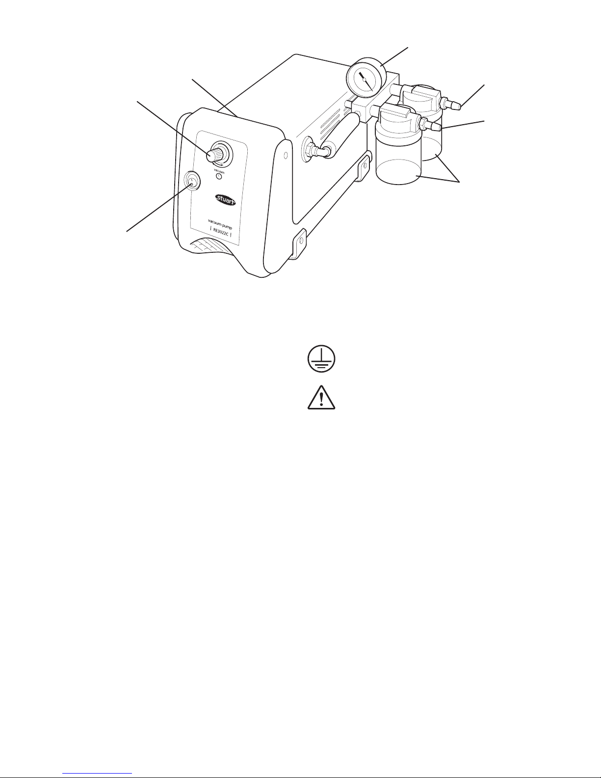
Vacuum gauge
Vacuum control
Carry handle
Power switch
Outlet
Catch pots
Figure 1
Inlet

1
IT IS IMPORTANT THAT THIS OPERATION IS
ONLY UNDERTAKEN BY A QUALIFIED
ELECTRICIAN
The unit is fitted with an IEC socket on a flying
lead at the rear of the instrument. This lead and
the suitable mains lead should be connected
together BEFORE connection to the mains
supply.
Should the mains lead need replacement a cable
of 1mm
2
of harmonised code H05W-F connected
to an IEC 320 plug should be used.
N.B. The UK mains lead is protected by a 10A
fuse mounted in the plug top.
IF IN DOUBT CONSULT A QUALIFIED
ELECTRICIAN
Safety advice
❖ If the mains supply is interrupted the units
will restart with its current settings on the
restoration of the electricity supply
❖ The pump is protected thermally. If the
thermal protection has been activated the
pump may restart unexpectedly when the
protection resets on cooling.
❖ Before use ensure that the outlet port is not
blocked. Before first use remove the cap fitted
for protection during transit.
❖ When using any equipment under vacuum
ensure adequate protective clothing is worn.
At a minimum this should be eye protection,
gloves and overalls.
❖ Do not operate the pump in an atmosphere
containing flammable or explosive vapours.
❖ Do not lift or carry the pump while it is
switched on or connected to the electricity
supply.
❖ The unit should be carried using the handle
located on the top (see fig 1).
Before use
See figure 1
Before installing and using the pump for the first
time please familiarise yourself with the general
layout and features of the pump.
In particular ensure you have correctly identified
the inlet and outlet ports. These are clearly
labelled on the top of the pump heads.
The on/off switch is located at the front of the
motor. Position (I) is on and position (0) is off.
There are plastic catch pots fitted to both outlet
and inlet ports to collect liquid ejected from the
outlet and prevent liquid ingress through the
inlet. The condition of the catch pots should be
checked before each use for cracks, chips or
signs of corrosion. Replace pots if defects are
found.
The inlet port is fitted with a vacuum gauge.
Pressure can be adjusted via the vacuum
regulator located at the front of the unit.
Installation
1. Choose a clean, dry and well ventilated area
where the pump will not be exposed to
moisture or flammable vapours.
2. The unit should be placed on a firm level
surface.
3. The pump is fitted with 4 rubber feet which
help reduce noise and creeping while the
pump is in use.
4. It is recommended that flexible hose
connections between the pump and the
vacuum system are kept as short as possible.
5. It is recommended that a flexible hose be
attached to the outlet port in order to lead
any fumes which pass through the pump
away from the working area, preferably into a
fume hood. Make sure this hose does not
become kinked and block the outlet path.
6. The tubing connectors on the inlet and outlet
ports accept tubing of 9mm internal diameter.

Operation
Do not use this pump to pump liquids.
1. Place the pump in the required location and
connect to the electricity supply.
2. Ensure that the outlet port is not blocked.
Never block the outlet port. If the pump
is run with the outlet blocked pressure
will build up in the pump which can
lead to the pump head bursting.
3. Ensure that the catch pots are empty and in
good condition. (see fig 1).
4. Switch the pump on and allow it to run for
a few minutes in order to warm up before
connection to the vacuum system.
5. Switch off and connect the pump to the
vacuum system.
6. Fully open the vacuum regulator (see fig 1)
by turning it anti-clockwise to the stop.
Note: It is necessary to completely turn the
vacuum regulating valve a number of times
before it is fully open. When fully open the
vacuum regulator will reach a stop point and
won’t be able to turn any further, take care not
to force the valve past this point.
7. Switch on the pump.
8. Slowly close the vacuum regulator until the
required vacuum level is shown on the
gauge (see fig 1).
Do not run the pump continuously for more
than 18 hours at blankoff. This will cause
the pump to overheat and seize.
9. After use release the vacuum before
switching off the pump. This can be done
either by venting the vacuum system or fully
opening the pump’s vacuum regulator.
10. Switch off the pump and disconnect from
the vacuum system.
2
11. It is recommended that after use the pump
be switched on again and run while
disconnected from the vacuum system for 2
minutes. The air passing through will purge
any vapours or condensate from the pump
heads and extend the diaphragm life.
Safety features
For the protection of the user and the pump
there are several safety features included (See fig 1).
1. Inlet Catch Pot
Liquid or particulate matter entering the pump
will cause damage and loss of performance. In
order to prevent this a catch pot is fitted to the
inlet port to trap such material before it can
enter the pump head.
If the pot becomes half full it should be emptied
as follows:
1. Switch off the pump and release the
vacuum
2. Unscrew the catch pot
3. Empty, clean and dry and examine the catch
pot and seals before screwing back into
place
4. Restart the pump.
2. Outlet Catch Pot
If a heavy vapour load is pumped it is possible
for condensation to occur inside the pump
because of the compression. The pump is
designed to cope with this load and will not be
damaged. However the resulting liquid will be
ejected from the outlet port.
The catch pot will collect this liquid preventing it
being ejected into the laboratory.
If the pot becomes half full it should be emptied
using the procedure outlined above for the inlet
pot. The contents of the pot should be disposed
of according to appropriate legislation.

Maintenance
Periodically clean the pump with a damp cloth
and a mild detergent solution
This vacuum pump is 100% oil-free. All bearings
are sealed for life and permanently lubricated.
Lubrication should not be attempted.
It is recommended that any servicing or repair is
only undertaken by suitably qualified personnel.
Only spare parts supplied by Cole-Parmer or its
agent should be used. Fitting of non-approved
parts may affect the performance of the safety
features of the instrument.
If in doubt, contact the Technical Department of
Cole-Parmer.
Tel: +44 (0)1785 810433
The following spare parts are available from your
laboratory supplier. For a comprehensive parts list
please contact the Service Department quoting
model and serial number.
Description Cat. No.
Catch pot RE3022C/1
Catch pot seal RE3022C/2
3
Warranty
Cole-Parmer warrants this instrument to be free
from defects in material and workmanship, when
used under normal laboratory conditions, for a
period of three (3) years. In the event of a
justified claim Cole-Parmer will replace any
defective component free of charge.
This warranty does NOT apply if damage is
caused by fire, accident, misuse, neglect,
incorrect adjustment or repair, damage by
installation adaptation, modification, fitting of
non-approved parts or repair by unauthorised
personnel.
Cole-Parmer Ltd.
Beacon Road,
Stone, Staffordshire,
ST15 0SA, United Kingdom
Tel: +44 (0)1785 810475
Email: cpservice@coleparmer.com
Web: www.stuart-equipment.com

4
Français
Manomètre à vide
Régulateur de
vide
Poignée de transport
Interrupteur
marche/arrêt
Sortie
Cuves de
récupération
Figure 1
Entrée
Pompe à vide Modèle
RE3022C
Instructions d’utilisation
Si le matériel n’est pas utilisé de la manière
décrite dans le présent manuel, la protection
fournie risque d’être amoindrie.
Cette pompe à vide Stuart est conçue pour
fonctionner dans les conditions suivantes :
❖ Utilisation en intérieur uniquement.
❖ Utilisation dans une zone bien ventilée.
❖ Plage de températures ambiantes de +5°C à
+40°C.
❖ Altitude jusqu’à 2000m.
❖ Humidité relative ne dépassant pas 80%.
❖ Fluctuations d’alimentation secteur ne
dépassant pas 10% de la tension nominale.
❖ Surtension de catégorie II IEC60364-4-443.
❖ Pollution de degré 2 IEC664.
❖ Utilisation avec une distance périphérique
minimale de 200mm des murs ou autres
éléments.
Installation électrique
Avant de procéder au branchement,
prenez le temps de lire et comprendre ce
manuel et assurez-vous que l’alimentation
de la ligne convient. Cette pompe
nécessite une alimentation nominale de
230V, 50Hz, monophasée ~.
La puissance consommée est de 150W.
CE MATERIEL DOIT ETRE RELIE A LA
TERRE
L’appareil est livré avec deux cordons secteur
équipés de prises IEC à connecter à l’instrument.
L’un présente une fiche britannique à 3 broches
et l’autre possède une fiche “Schuko” à 2
broches pour le branchement sur secteur. Choisir
le cordon approprié pour votre installation
électrique et jeter l’autre.
Si ni l’un ni l’autre ne convient, prendre le
cordon équipé de la fiche britannique et
remplacer cette fiche par une prise de
remplacement adaptée. Ceci implique de couper
la fiche moulée, préparer le câble et le connecter
à la fiche à monter, en conformité avec les
instructions de cette dernière.

Les fils du câble secteur ont les couleurs
suivantes:
MARRON - PHASE
BLEU - NEUTRE
VERT/JAUNE - TERRE
IL EST IMPORTANT QUE CETTE OPERATION
NE SOIT EFFECTUEE QUE PAR UN
ELECTRICIEN QUALIFIE
L’appareil est équipé d’une prise IEC sur un
cordon volant à l’arrière de l’instrument. Ce
cordon et le cordon secteur adapté devront être
connectés l’un à l’autre AVANT branchement à
l’alimentation au secteur.
Si le cordon secteur doit être remplacé, un câble
de 1mm
2
au code harmonisé H05W-F connecté à
une fiche IEC 320 devra être utilisé.
N.B.: Le cordon secteur britannique est protégé
par un fusible 10A monté sur le haut de la fiche.
EN CAS DE DOUTE, CONSULTER UN
ELECTRICIEN QUALIFIE
Conseil de sécurité
❖ Si l’alimentation secteur est interrompue,
l’appareil redémarrera avec ses réglages
actuels au rétablissement de l’alimentation
électrique.
❖ La pompe est protégée sur le plan thermique.
Si cette protection thermique a été activée, la
pompe peut redémarrer de façon inattendue
lorsque la protection se réinitialise au
refroidissement.
❖ Avant utilisation, s’assurer que l’orifice de
sortie n’est pas obstrué. Avant la première
utilisation, déposer le bouchon installé pour la
protection durant le transit.
❖ Lors de l’utilisation d’un quelconque matériel
sous vide, veiller à porter des vêtements de
protection adéquats. Il devra s’agir au
minimum d’une protection oculaire, de gants
et d’une combinaison de travail.
❖ Ne pas faire fonctionner la pompe dans une
atmosphère contenant des vapeurs
inflammables ou explosives.
❖ Ne pas soulever ni porter la pompe alors
qu’elle est sous tension ou connectée à
l’alimentation électrique.
❖ L’appareil devra être transporté à l’aide de la
poignée située sur le dessus (voir fig. 1).
Avant utilisation
Voir Figure 1.
Avant d’installer la pompe et de l’utiliser pour la
première fois, veuillez vous familiariser avec son
agencement général et ses caractéristiques.
En particulier, assurez-vous que vous avez
correctement identifié les orifices d'entrée et de
sortie. Ils sont clairement étiquetés au-dessus des
têtes de pompe.
L'interrupteur marche/arrêt se trouve au-devant
du moteur. La position (1) est la position de
marche, et la position (0) est la position d'arrêt.
Des cuves de récupération en plastique équipent
les deux orifices d'entrée et de sortie pour
collecter le liquide éjecté de la sortie et empêcher
lapénétration de liquide dans l'entrée. L’état des
cuves de récupération devra être vérifié avant
chaque utilisation pour contrôler l’absence de
fissures, éclats ou signes de corrosion. Remplacer
les cuves si elles présentent des défauts.
L'orifice d'entrée est équipé d'un manomètre à
vide. La pression peut se régler en utilisant le
régulateur de vide qui se trouve au-devant
de l'appareil.
Installation
1 Choisir une zone propre, sèche et bien
ventilée, où la pompe ne sera pas exposée à
l’humidité ni aux vapeurs inflammables.
2 L’appareil devra être placé sur une surface
stable et de niveau.
3 La pompe est équipée de 4 pieds à ventouse
caoutchouc qui aident à la réduction du bruit
et au glissement lorsque la pompe est en
service.
5

6
4 Il est recommandé de garder les
raccordements sous tuyaux flexibles entre la
pompe et le circuit de pompage à vide aussi
courts que possible.
5 Il est recommandé de fixer un tuyau flexible
à l’orifice de sortie pour conduire hors de la
zone de travail toute fumée traversant la
pompe, de préférence dans une hotte.
Vérifier que ce flexible ne présente pas de
coudes obstruant la sortie.
6 Les raccords de tubulure sur les orifices
d’entrée et de sortie acceptent des tubes de
diamètre interne 9mm.
Fonctionnement
Ne pas utiliser cette pompe pour aspirer des
liquides.
1 Placer la pompe à l’emplacement voulu et la
brancher à l’alimentation électrique.
2 S’assurer que l’orifice de sortie n’est pas
bouché.
Ne jamais boucher l’orifice de sortie. Si la
pompe fonctionne avec l’orifice de sortie
bouché, la pression va s’accumuler dans la
pompe, ce qui peut conduire à l’éclatement
de la tête de pompe.
3 S’assurer que les cuves de récupération sont
vides et en bon état (voir fig. 1).
4 Mettre la pompe sous tension et la laisser
tourner quelques minutes afin de la
préchauffer avant raccordement au circuit de
pompage à vide.
5 Mettre la pompe hors tension et la raccorder
au circuit de pompage à vide.
6 Ouvrir à fond le régulateur de vide (voir fig.
1) en le tournant dans le sens anti-horaire
jusqu’à la butée.
7 Mettre la pompe sous tension. Ceci peut
demander un nombre considerable de
tours jusqu'à ce qu'il s'arrete.
8 Fermer lentement le régulateur de vide
jusqu’à ce que le niveau de vide voulu soit
indiqué sur le manomètre (voir fig. 1).
Ne pas faire fonctionner la pompe de façon
continue pendant plus de 18 heures en
circuit fermé. Ceci provoquerait la surchauffe
et la rupture de la pompe.
9 Après utilisation, relâcher le vide avant de
mettre la pompe hors tension. Cela peut se
faire soit en éventant le circuit de pompage à
vide, soit en ouvrant complètement le
régulateur de vide de la pompe.
10 Mettre la pompe hors tension et la
débrancher du circuit de pompage à vide.
11 Après utilisation, il est recommandé de
remettre la pompe sous tension et de la faire
fonctionner une fois déconnectée du circuit
de pompage à vide pendant 2 minutes. L’air
qui la traverse va purger les vapeurs ou la
condensation des têtes de pompe et
prolonger la durée de vie du diaphragme.
Caractéristiques de
sécurité
Pour la protection de l’utilisateur et de la pompe,
plusieurs caractéristiques de sécurité ont été
prévues (voir Figure 1).
1. Cuve de récupération d’entrée
Les matières liquides ou particules entrant dans
la pompe provoqueront des dégâts et des pertes
de performances. Afin de l’éviter, une cuve de
récupération est montée à l’orifice d’entrée pour
piéger ces matières avant qu’elles puissent entrer
dans la tête de la pompe.
Si la cuve vient à être à moitié pleine, elle devra
être vidée comme suit :
1 Mettre la pompe hors tension et relâcher le
vide.
2 Dévisser la cuve de récupération.
3 Vider, nettoyer et sécher puis examiner la
cuve de récupération et les joints avant de
les revisser en place.
4 Redémarrer la pompe.
 Loading...