

Assembly and operating instructions
Instructions de montage et d’utilisation
Istruzioni per il montaggio e per l’uso
Instrucciones de ensamblaje y funcionamiento
Montage- und Bedienungsanleitung
Rotary Evaporators
RE300 RE301 RE302
RE300P RE301P RE302P
2
Before use
If the equipment is not used in the manner described in this
manual the protection provided by the equipment may be
impaired.
Bibby Scientific rotary evaporators are designed to operate under the
following conditions:
❖ For indoor use only
❖ Use in a well ventilated area
❖ Ambient temperature range +5°C to +40°C
❖ Altitude up to 2000m
❖ Relative humidity not exceeding 80%
❖ Mains supply voltage fluctuations not
greater than ±10% of nominal
❖ Over voltage category 2 IEC 60364-4-443
❖ Pollution degree 2 IEC664
Rotary Evaporators
RE300 RE301 RE302
RE300P RE301P RE302P
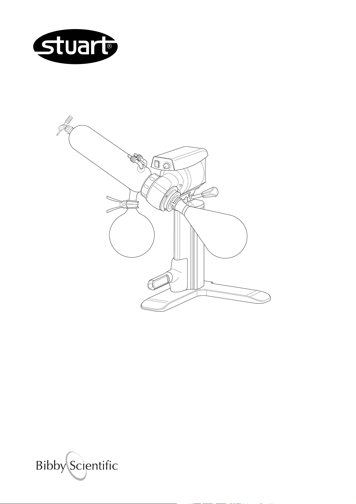
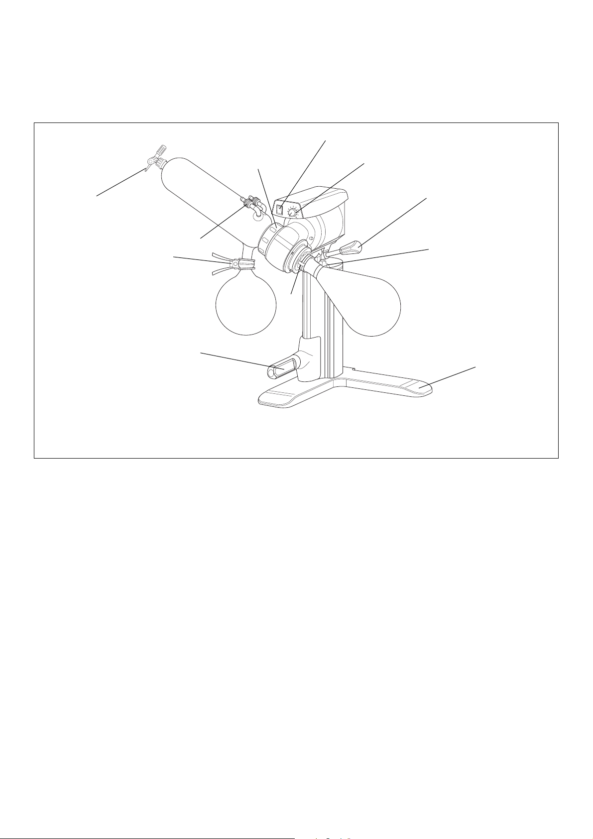
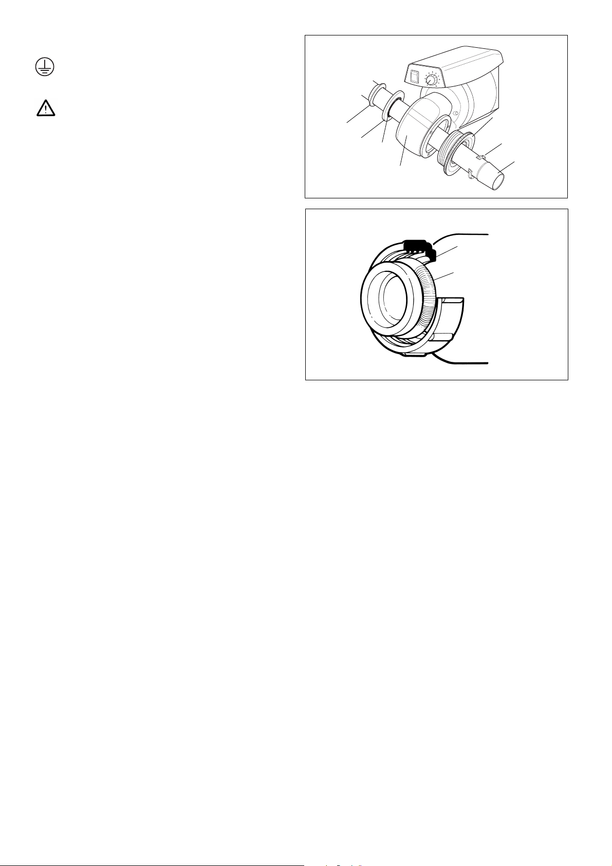
Figure 1 Assembly
3
7
1
9
4
5
Twist grip height adjustment handle
Vacuum and water connections
6
On/Off switch
Rotating speed control
Glass angle control
Additional height
adjustment knob
2
Location & Services
In order to get the optimum performance from your Bibby Scientific
rotary evaporator careful consideration should be given to the
intended location. Please study the following notes before
commencing assembly.
Choose a convenient location, which will allow easy access to both
rotating and receiving flask.
In order to allow the glassware to be raised and lowered, a
minimum headroom of 850mm is required.
The location should have access to the following services:
Cold water supply capable of delivering 60l/hr is required for RE300,
RE300P, RE301, RE301P.
Electricity supply
Drain
Vacuum line (optional)
Assembly and operating instructions

3
Electrical Supply
THIS EQUIPMENT MUST BE EARTHED
Before connection please read and understand this instruction
manual and ensure that the line supply corresponds to that
shown on the rating plate. Bibby Scientific rotary evaporators
require a supply rated at 220-240V, 50/60Hz, single phase,~.
The power consumption of the rotary evaporator is 50W.
F3.15AL (20x5mm) fuses fitted in both live and neutral lines.
IF IN DOUBT CONSULT A QUALIFIED ELECTRICIAN
The unit is supplied with two mains leads fitted with IEC plugs for
connection to the instrument. One has a U.K. 3 pin plug and the
other has a 2-pin “Shuko” plug for connection to the mains.
Choose the lead appropriate for your electrical installation and
discard the other.
Should neither lead be suitable, take the lead with the U.K. plug and
replace the plug with a suitable alternative. This involves cutting off
the moulded plug, preparing the cable and connecting to the
rewireable plug in accordance with its instructions.
IT IS IMPORTANT THAT THIS OPERATION SHOULD ONLY BE
UNDERTAKEN BY A QUALIFIED ELECTRICIAN
The wires in the mains cable are coloured as follows:
BROWN - LIVE
BLUE - NEUTRAL
GREEN/YELLOW - EARTH
The unit is fitted with an IEC socket at the rear of the instrument for
connection of the mains lead. The appropriate mains lead should be
connected BEFORE connection to the mains supply.
Should the mains lead need replacement a cable of 1mm
2
of
harmonised code H05W-F connected to an IEC 320 plug should be
used.
N.B. The UK mains lead is protected by a 10A fuse mounted in the
plug top.
Safety Advice before Use
1. If the jacking mechanism is to be raised without the
glassware fitted great care must be taken. Without the
weight of the glass the jack will rise rapidly and can cause
damage to the mechanism. Unlock the jack carefully while
applying downward pressure to control the movement.
2. As the apparatus is likely to be used under vacuum, before
operation, examine all glassware carefully for scratches or
chemical etching. Use of damaged glassware under
vacuum could result in an implosion. In any case it is
recommended that the apparatus be operated behind a
safety screen.
3. Do not use the equipment in a hazardous atmosphere or
for mixing of hazardous materials.
4. Special care should be taken when using the equipment
with flammable solvents. The unit is not spark or explosion
proof.
5. In case of mains interruption, a fault or mechanical failure,
the unit will continue to operate on removal of the fault.
6. Beware of safety issues associated with rotating glassware
and when jacking glassware up and down.
Assembly
If the jacking mechanism is to be raised without the glassware
fitted great care must be taken. Without the weight of the
glass the jack will rise rapidly and can cause damage to the
mechanism. Unlock the jack carefully while applying
downward pressure to control the movement.
1. Unpack the rotary evaporator and identify the following
components:
Item Component Catalogue
No Number
1 Condenser RE100/CO or RE200/VC or
RE200/CF and RE200/CFD
2 Conical joint clip KCM29
3 Feed/vacuum release adapter RE100/VR
4 Florentine flask 1L FD1L/4RE
5 Receiving flask 1L RE100/RF/1L
6 Rotary evaporator motor stand RE300/MS
7 Spherical joint clip JC35
8 Vapour tube RE100/VT or RE100/VT/CF
9 Grey retaining cap
10 Circular metal spring
11 Vacuum seal
12 Sub-seal
13 Retaining clip
- UK lead
- European lead
- Spare fuse
12
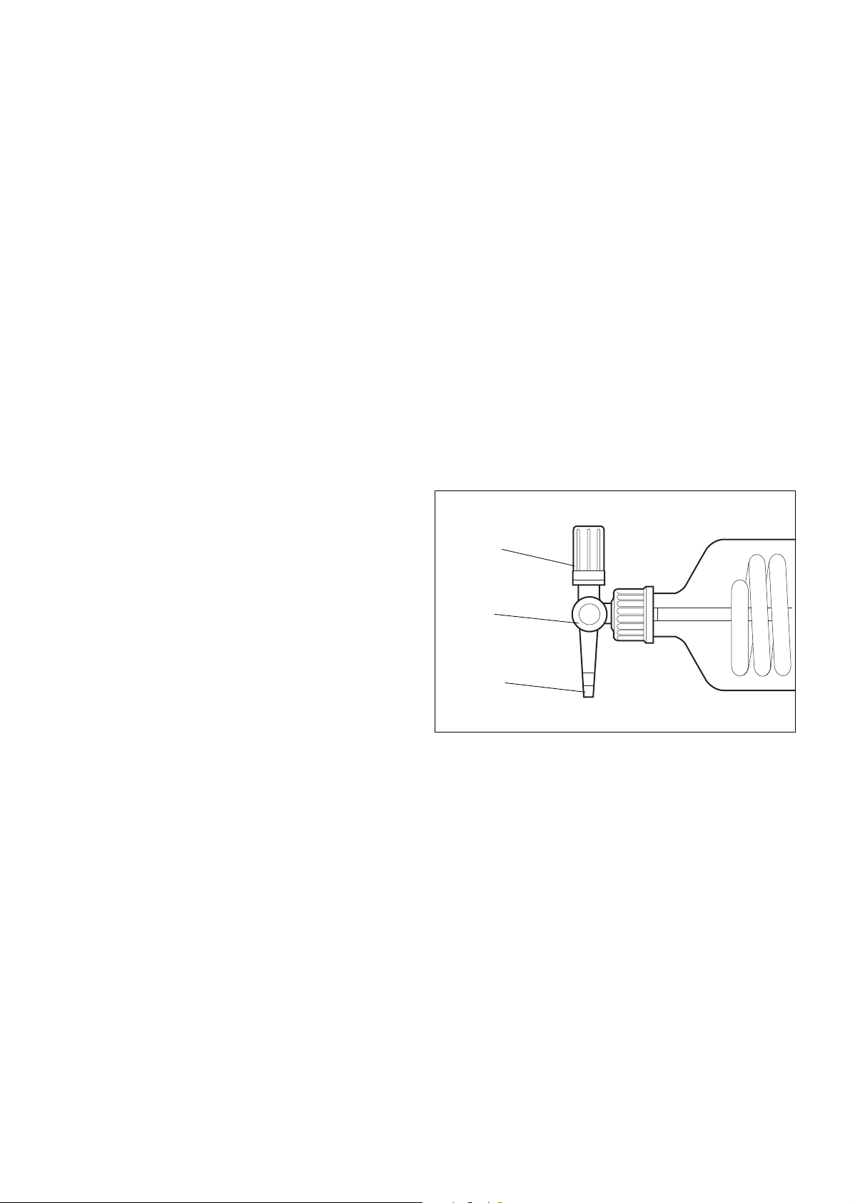
11
Bearing house
Figure 2
Figure 3
Plastic screw bush
10
1
9
13
8
Spring
All components are
included in the rotary
evaporator motor stand
box
4
RE302, RE302P First remove the plastic connector at the back
of the condenser and fit into the hose. Secure with a suitable
clip, e.g. Jubilee. The connector and hose may now be fitted to
the vacuum line.
Note: A plastic cover is provided to reduce evaporation of cooling
agent.
Your rotary evaporator is now ready to be used.
Operation
Batch Operation
a) Remove the rotating flask (4) from the vapour tube (8) and fill
with the liquid to be evaporated. Ensure that the flask is never
more than half full. Secure the flask onto the conical joint using
the clip (2)
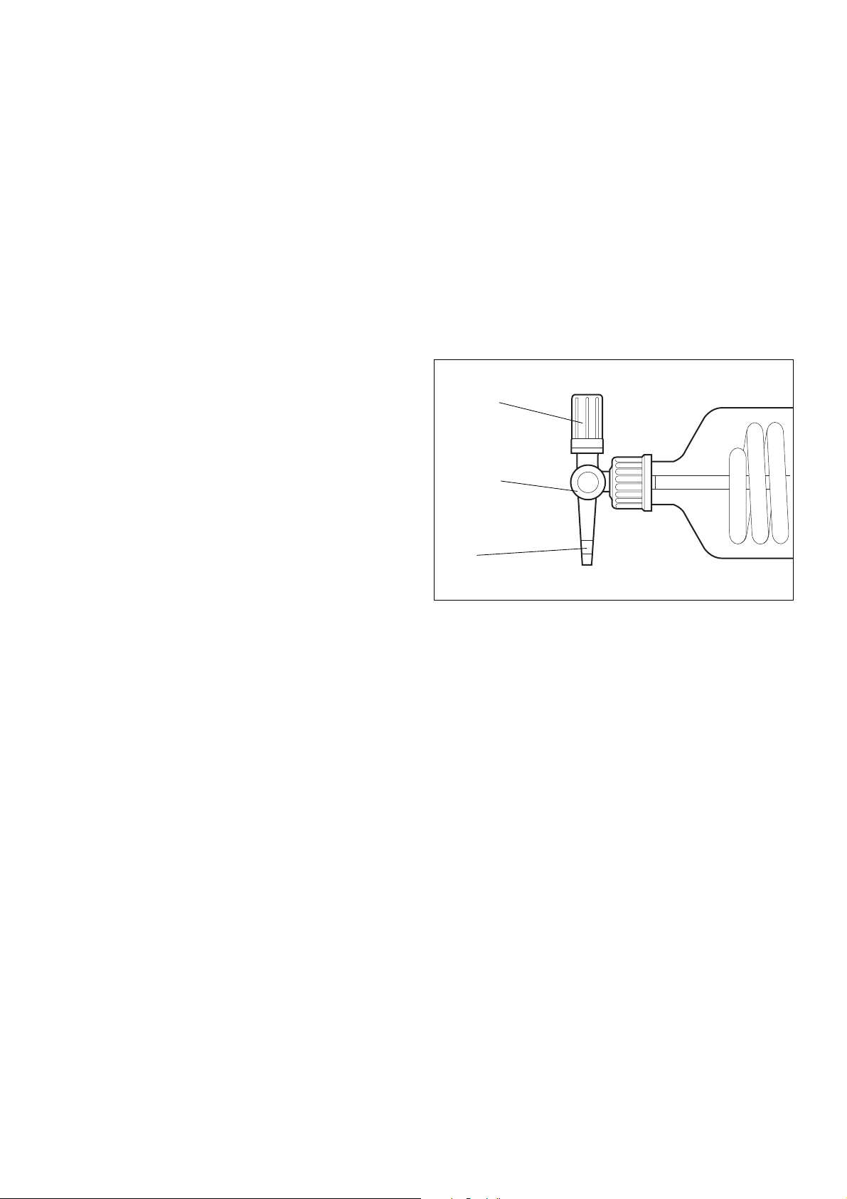
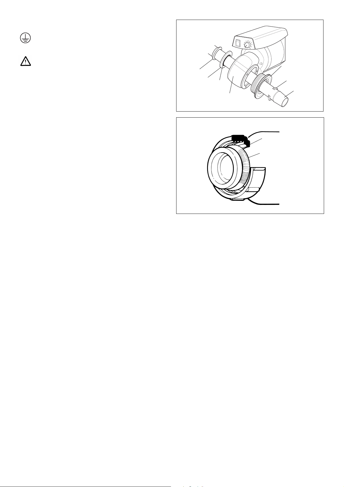
b) Examine the feed/release adapter (3) and ensure that both the
stopcock and vacuum release screwcap are closed (see fig. 4).
c) Ensure that water is flowing through the condenser at approx.
60l/hr (RE300 and RE301) or that the cold trap is filled with ice
or dry ice (RE302).
d) Ensure the speed control is set to 0.
e) Switch on the electricity supply.
f) Raise the glassware assembly to its highest position by turning
the handle anticlockwise. Note that the mechanism is spring
loaded. Once at the right height, turn the handle clockwise to
secure the position.
Note: Further height adjustment can be made by unscrewing the
additional height adjustment knob at the back of the stand (see
fig 1).
g) Place a suitable water bath directly under the rotating flask.
N.B. A water bath designed for use with the RE300 is
available from Bibby Scientific, code RE300B. Please
contact the sales office for details.
h) Lower the glassware until the rotating flask is partially immersed
in the water.
N.B. Ensure that the glassware does not touch the bath
and that no water overflows as the flask is immersed.
i) Switch the on/off switch to the on position. The green switch will
illuminate.
j) Set the speed control to the desired speed ensuring that rotation
is not so fast that water is splashed out of the bath.
2. Place the stand on a level surface. You will require easy access to
a water supply, drain, electric power and vacuum line to use your
rotary evaporator.
3. Pass the plain end of the vapour tube (8) through the right side
of the motor assembly and push into position until it locates
firmly behind the spring clip. The conical joint should be to the
right of the motor when viewed from the front.
4. Place the main vacuum seal (11) and sub-seal (12) onto the plain
end of the vapour tube (left) and slide them down until they
locate in the bearing housing. It is important that these
elements are fitted in the correct order and that the spring
loaded side of the main seal faces the bearing housing (see
fig.2).
5. Place the retaining clip (13) on the jointed side of the vapour
tube (right) and slide until it clips in the plastic screw bush (fig 2).
6. Place the grey retaining cap (9) over the butt joint of the
condenser (1) with the screwthread facing outwards and retain in
position with the circular spring (10) (see figure 3).
7. Place the condenser over the vapour tube so that it butts up to
the vacuum seal. Ensure the spherical joint faces downwards.
Secure by screwing the retaining cap onto the bearing housing.
If using a RE300 diagonal coil condenser, check that the vapour
tube is central and will not foul the condenser cooling coil.
8. The condenser may now be set to the required angle:
RE300 and RE300P Diagonal position
RE301, RE301P and RE302, RE302P Vertical position
9. Support the condenser while loosening the glass angle control.
10. Position condenser and tighten the control.
11. Hold the receiving flask (5) in position and secure with the
spherical joint clip (7).
12. Place the rotating flask (4) onto the end of the vapour tube and
secure using the conical joint clip (2).
13. Remove the grey plastic screwcap from the narrow end of the
condenser and assemble it to the feed/vacuum release adapter (3)
(see fig. 4).
14. Pass the PTFE tube through the condenser and vapour tube so
that the end is inside the rotating flask. Note that for the RE301
and RE302, the PTFE tube may have to be reduced in length to
fit into the Florentine flask (see fig. 4).
15. Secure by tightening the screw cap.
16. RE302 and RE302P only: Assemble the drain stopcock
(RE200/CFD) to the condenser using the grey plastic cap located
on the lower side arm.
17. To connect the condenser to the water supply, drain and vacuum
line, flexible hose of 9mm I.D. is required. Ensure you identify
every connection correctly before starting. Note tubing suitable
for use under vacuum must be used for the vacuum connection.
RE300, RE300P First remove the plastic connectors from the
condenser and fit into the hose. Secure with a suitable clip, e.g.
Jubilee. The connectors and hose may now be fitted to the inlet
and outlet water connections on the condenser (bottom two
connections linked to the coil). Proceed in the same way for the
vacuum connection (top connection).
RE301, RE301P First remove the plastic connectors from the
condenser and fit into the hose. Secure with a suitable clip, e.g.
Jubilee. The connectors and hose may now be fitted to the inlet
and outlet water connections on the condenser (bottom two
connections linked to the coil). Proceed in the same way for the
vacuum connection (top connection).
Continuous feed
stopcock
Continuous feed
inlet
Vacuum release
screwcap
Figure 4

5
k) If evaporation at reduced pressure is required a vacuum line
should be attached to the vacuum side arm on the condenser.
Turn on the vacuum and set to required value.
N.B. A vacuum pump designed for use with the RE300 is
available from Bibby Scientific, code RE2022C. Please
contact the sales office for details.
l) Set the temperature of the water bath as required.
m) When evaporation is complete release the vacuum by slowly
unscrewing the vacuum release screwcap. Set the rotation speed
to 0 and raise the glassware clear of the bath.
Continuous Feed Operation
When the apparatus is used under reduced pressure it is possible to
replenish the liquid in the rotating flask without interrupting the
evaporation or removing the flask.
The following procedure should be adopted.
a) Attach a length of flexible tubing to the continuous feed inlet of
the feed/release adapter (see fig.4).
b) Carry out instructions b-k for batch operation.
c) Immerse the free end of the flexible tubing into the container
holding the liquid to be evaporated. Ensure there is no strain on
the feed/release adapter.
d) With the apparatus under vacuum slowly open the stopcock on
the feed/release adapter. The vacuum will draw liquid into the
rotating flask.
e) Close the stopcock when sufficient liquid has entered the flask
Further quantities of liquid may be added during evaporation by
reopening the stopcock.
N.B. Ensure there is sufficient capacity in the flask to cope
with the addition. Never fill the flask more than half full.
N.B. Ensure there is sufficient capacity in the receiving flask
to cope with the condensation.
N.B. This evaporator should not be used with rotating
flasks bigger than 2 litres or receiving flasks bigger than 1
litre capacity.
f) If the receiving flask should require emptying during operation
the following procedure should be adopted:
i Release the vacuum and stop rotation
ii Raise the glassware clear of the water bath
iii Wait until boiling stops and liquid stops dripping into the
receiving flask
iv The receiving flask may now be removed.
g) When evaporation is complete release the vacuum by slowly
unscrewing the vacuum release screwcap. Set the rotation speed
to 0 and raise the glassware clear of the bath.
Care and Maintenance
IMPORTANT: Before commencing any maintenance operation or
replacement of components parts the unit should be isolated
from the electricity supply, water supply and vacuum line.
These operations should only be undertaken by suitably
qualified personnel.
Note: F3.15AL (20x 5mm) fuses fitted in both live and neutral
lines.
Glassware
All glassware parts should be cleaned regularly and examined for
scratches, cracks and chemical etching. Replace any damaged parts.
Plastic coated glassware
The plastic coated glassware should not be exposed to temperature
above 80°C and is not dishwasher proof.
Cleaning
The main stand and motor should be cleaned using a mild detergent
solution.
Vacuum Seal
It is recommended that the vacuum seal be regularly washed with
distilled or deionised water and allowed to dry naturally.
Removal of the Vacuum Seal
a) Remove the rotating and receiving flasks
b) Remove feed/release adapter
c) Remove condenser
d) Withdraw vapour tube from the bearing housing by completely
unscrewing the plastic screw bush on the right side of the bearing
house.
e) The vacuum seal may now be removed.
f) Reassemble following the assembly instructions in this manual.
Servicing
It is recommended that any servicing or repair is only undertaken by
suitably qualified personnel.
Only spare parts supplied by Bibby Scientific or its agent should be
used. Fitting of non-approved parts may affect the performance of the
safety features of the instrument.
If in doubt, contact the Technical Service Department of
Bibby Scientific Ltd.
Stone, Staffordshire ST15 0SA
United Kingdom
Tel: +44 (0)8449 360234
Fax: +44 (0)8449 360235
e-mail info@bibby-scientific.com
www.bibby-scientific.com

6
Spares
The following spare parts are available from your laboratory supplier.
(For a comprehensive parts list or circuit and wiring diagrams please
contact the Technical Service Department of Bibby Scientific Ltd
quoting model and serial number).
Cat. No. Description
RE100/CO Diagonal coil condenser (feed tube not included)
RE200/VC Vertical coil condenser (feed tube not included)
RE200/CF Cold finger condenser (feed tube and drain not included)
RE100/COP Diagonal coil condenser plastic coated (feed tube not included)
RE200/VCP Vertical coil condenser plastic coated (feed tube not included)
RE200/CFP Cold finger condenser plastic coated (feed tube and drain not included)
RE200/CFD Drain for cold finger condenser
RE100/VR Feed tube
RE100/VT Vapour tube for diagonal condenser
RE100/VT/CF Vapour tube for vertical coil and cold finger condensers
RE100/VS Vacuum seal
FD1L/4RE Florentine flask 1000ml
FD1L/4REP Florentine flask 1000ml plastic coated
RE100/RF/1L Receiving flask 1000ml
RE100/RF/1LP Receiving flask 1000ml plastic coated
KCM29 Conical joint clip
JC35 Spherical joint clip
Warranty
Bibby Scientific Ltd warrants this mechanical and electrical
equipment to be free from defects in material and workmanship,
when used under normal laboratory conditions, for a period of three
(3) years. In the event of a justified claim Bibby Scientific will replace
any defective component free of charge.
This warranty does NOT apply if damage is caused by fire, accident,
misuse, neglect, incorrect adjustment or repair, damage by
installation adaptation, modification, fitting of non-approved parts or
repair by unauthorised personnel.
This warranty does not apply to the glassware or vacuum seal.
These products meet the applicable EC
harmonised standards for radio frequency
interference and may be expected not to
interfere with, or be affected by, other
equipment with similar qualifications. We
cannot be sure that other equipment used in
its vicinity will meet these standards and so we
cannot guarantee that interference will not
occur in practice. Where there is a possibility
that injury, damage or loss might occur if
equipment malfunctions due to radio
frequency interference, or for general advice
before use, please contact the Technical
Department of Bibby Scientific.
7
Avant utilisation
Si le matériel n’est pas utilisé de la manière décrite dans le
présent manuel, la protection fournie risque d’être amoindrie.
Les évaporateurs rotatifs Bibby Scientific sont conçus pour fonctionner
dans les conditions suivantes :
❖ Utilisation en intérieur uniquement
❖ Utilisation dans une zone bien ventilée
❖ Plage de températures ambiantes de +5°C à +40°C
❖ Altitude jusqu’à 2000m
❖ Humidité relative ne dépassant pas 80%
❖ Fluctuations d’alimentation secteur ne dépassant pas 10% de la
tension nominale
❖ Surtension de catégorie II IEC 60364-4-443
❖ Pollution de degré 2 IEC664
Evaporateurs rotatifs Français
RE300 RE301 RE302
RE300P RE301P RE302P
Figure 1 Montage
3
7
1
9
4
5
Poignée à serrage tournant de réglage
de hauteur
Raccords de vide et eau
6
Interrupteur marche/arrêt
Molette de commande de vitesse
Commande d’angle du verre
Molette de réglage de hauteur
supplémentaire
Positionnement et raccordements
Afin d’obtenir les performances optimales de votre évaporateur
rotatif Bibby Scientific, l’emplacement prévu devra être
attentivement pris en considération. Veuillez étudier les notes
suivantes avant de commencer le montage.
Choisir un emplacement commode, permettant un accès aisé aux
deux ballons rotatif et récepteur.
Afin de permettre de monter et descendre la verrerie, un
dégagement minimum de 850mm est nécessaire.
L’emplacement devra avoir accès aux raccordements suivants :
❖ Une alimentation en eau froide pouvant fournir 60 l/h est
nécessaire pour RE300, RE300P, RE301, RE301P.
❖ Alimentation électrique.
❖ Vidange.
❖ Ligne de vide (en option)
Instructions de montage et d’utilisation
2
8
Alimentation électrique
CE MATERIEL DOIT ETRE RELIE A LA TERRE
Avant de procéder au branchement, prenez le temps de lire et
comprendre ce manuel d’instructions et assurez-vous que
l’alimentation de la ligne correspond à celle indiquée sur la
plaque signalétique. Les évaporateurs rotatifs Bibby Scientific
nécessitent une alimentation nominale de 220-240V, 50/60Hz,
~, monophasée. La puissance consommée d’un évaporateur
rotatif est de 50W. Des fusibles F3,15AL (20x5mm) sont
montés sur les lignes de phase et neutre.
EN CAS DE DOUTE, CONSULTER UN ELECTRICIEN QUALIFIE
L’appareil est livré avec deux cordons secteur équipés de prises IEC à
connecter à l’instrument. L’un présente une fiche britannique à 3
broches et l’autre possède une fiche “Shuko” à 2 broches pour le
branchement sur secteur. Choisir le cordon approprié pour votre
installation électrique et jeter l’autre.
Si ni l’un ni l’autre ne convient, prendre le cordon équipé de la fiche
britannique et remplacer cette fiche par une prise de remplacement
adaptée. Ceci implique de couper la fiche moulée, préparer le câble
et le connecter à la fiche à monter, en conformité avec les
instructions de cette dernière.
IL EST IMPORTANT QUE CETTE OPERATION NE SOIT EFFECTUEE
QUE PAR UN ELECTRICIEN QUALIFIE
Les fils du câble secteur ont les couleurs suivantes :
MARRON - PHASE
BLEU - NEUTRE
VERT/JAUNE - TERRE
L’appareil est équipé d’une prise IEC à l’arrière de l’instrument pour
le branchement du cordon secteur. Le cordon secteur approprié
devra être connecté AVANT branchement à l’alimentation au secteur.
Si le cordon secteur doit être remplacé, un câble de 1mm
2
au code
harmonisé H05W-F connecté à une fiche IEC 320 devra être utilisé.
N.B. : Le cordon secteur britannique est protégé par un fusible 10A
monté sur le haut de la fiche.
Conseils de sécurité avant utilisation
1. Si le mécanisme de réglage en hauteur doit être relevé
sans que la verrerie soit installée, une grande prudence
doit être observée. Sans le poids du verre, le réglage va
monter rapidement et risque d’endommager le mécanisme.
Déverrouiller prudemment le réglage tout en exerçant une
pression vers le bas pour contrôler le mouvement.
2. Comme il est probable que l’appareil sera utilisé sous vide,
avant utilisation, examiner attentivement toute la verrerie
et vérifier l’absence de rayures ou d’attaques chimiques.
L’utilisation sous vide d’une verrerie endommagée pourrait
entraîner une implosion. Dans tous les cas, il est
recommandé de faire fonctionner l’appareil derrière un
écran de sécurité.
3. Ne pas utiliser ce matériel dans une atmosphère
dangereuse ou pour mélanger des matières dangereuses.
4. Une prudence particulière devra être observée lors de
l’utilisation de ce matériel avec des solvants inflammables.
L’appareil n’est pas anti-étincelant ni anti-déflagrant.
5. En cas de coupure secteur, de panne ou de défaillance
mécanique, l’appareil va continuer à fonctionner une fois
le défaut rectifié.
6. Attention aux questions de sécurité associées à la verrerie
rotative et à la montée et descente de la verrerie.
Montage
Si le mécanisme de réglage en hauteur doit être relevé sans
que la verrerie soit installée, une grande prudence doit être
observée. Sans le poids du verre, le réglage va monter
rapidement et risque d’endommager le mécanisme.
Déverrouiller prudemment le réglage tout en exerçant une
pression vers le bas pour contrôler le mouvement.
1. Déballer l’évaporateur rotatif et identifier les composants suivants:
Repère Composant Référence
N° catalogue
1 Condenseur RE100/CO ou RE200/VC ou
RE200/CF et RE200/CFD
2 Pince d’assemblage conique KCM29
3 Adaptateur d’alimentation
/libération du vide RE100/VR
4 Ballon florentin 1L FD1L/4RE
5 Ballon récepteur 1L RE100/RF/1L
6 Support moteur
de l’évaporateur rotatif RE300/MS
7 Pince d’assemblage sphérique JC35
8 Tube de vapeur RE100/VT ou RE100/VT/CF
9 Chapeau de fixation gris
10 Ressort métallique circulaire
11 Joint de vide
12 Sous-joint
13 Collier de fixation
- Cordon britannique
- Cordon européen
- Fusible de rechange
12
11
Ressort
Carter de roulement
Figure 2
Figure 3
Bague de vissage
plastique
13
8
Tous ces composants sont
inclus dans la boîte du
support moteur de
l’évaporateur rotatif
10
1
9
RE301, RE301P Déposer d’abord les connecteurs en plastique
du condenseur et les installer dans le tuyau. Les fixer à l’aide
d’un collier adapté, par ex. Jubilee. Les connecteurs et le tuyau
peuvent maintenant être montés sur les branchements d’entrée
et de sortie d’eau du condenseur (les deux raccords du bas reliés
au serpentin). Procéder de la même façon pour le branchement
de la ligne de vide (raccord du haut).
RE302, RE302P Déposer d’abord le connecteur en plastique à
l’arrière du condenseur et le monter dans le tuyau. Le fixer à
l’aide d’un collier adapté, par ex. Jubilee. Le connecteur et le
flexible peuvent maintenant être montés sur la ligne de vide.
Note : Une enveloppe en plastique est fournie pour réduire
l’évaporation de l’agent de refroidissement.
Votre évaporateur rotatif est maintenant prêt à être utilisé.
Fonctionnement
Utilisation en lots
a) Déposer le ballon rotatif (4) du tube de vapeur (8) et le remplir du
liquide à évaporer. Veiller à ce que le ballon ne soit jamais plus
qu’à moitié plein. Fixer le ballon sur l’assemblage conique à l’aide
de la pince (2)
b) Examiner l’adaptateur d’alimentation/libération (3) et s’assurer
que le robinet et le capuchon vissé de libération de vide sont
fermés (voir fig. 4).
c) S’assurer que l’eau s’écoule dans le condenseur à environ 60 l/h
(RE300 et RE301) ou que le piège froid est rempli de glace ou de
glace sèche (RE302).
d) S’assurer que la commande de vitesse est réglée sur 0.
e) Mettre l’appareil sous tension.
f) Relever le montage de verrerie à sa position la plus haute en
tournant la poignée dans le sens anti-horaire. Noter que le
mécanisme est sous charge de ressort. Une fois la verrerie à la
bonne hauteur, tourner la poignée dans le sens horaire pour
bloquer la position.
Note : un autre réglage de hauteur peut être réalisé en dévissant
la molette de commande à l’arrière du support (voir fig. 1).
g) Placer un bain-marie adapté directement sous le ballon rotatif.
N.B. : Un bain-marie conçu pour être utilisé avec le RE300
est disponible chez Bibby Scientific, code RE300B. Veuillez
contacter l’agence commerciale pour les détails.
h) Abaisser la verrerie jusqu’à ce que le ballon rotatif soit
partiellement immergé dans l’eau.
N.B. : Veiller à ce que la verrerie ne touche pas le bainmarie et à ce que l’eau ne déborde pas au moment de
l’immersion du ballon.
9
2. Placer le support sur une surface de niveau. Vous aurez besoin
d’un accès aisé à une alimentation en eau, une vidange, une
alimentation électrique et une ligne de vide pour utiliser votre
évaporateur rotatif.
3. Passer l’extrémité pleine du tube de vapeur (8) par le côté droit
du bloc moteur et l’enfoncer en position jusqu’à ce qu’il se
mette solidement en place derrière le collier à ressort.
L’assemblage conique devrait être sur la droite du moteur vu de
devant.
4. Placer le joint de vide principal (11) et le sous-joint (12) sur
l’extrémité pleine du tube de vapeur (à gauche) et les faire glisser
vers le bas jusqu’à ce qu’ils prennent place dans le carter de
roulement. Il est important que ces éléments soient montés dans
le bon ordre et que le côté sous charge de ressort du joint
principal soit tourné vers le carter de roulement (voir fig. 2).
5. Placer le collier de fixation (13) sur le côté assemblé du tube de
vapeur (à droite) et le faire glisser jusqu’à ce qu’il s’accroche dans
la bague de vissage plastique (fig. 2).
6. Placer le chapeau de fixation gris (9) sur le joint d’about du
condenseur (1), les filets de vissage tournés vers l’extérieur, et le
maintenir en position avec le ressort circulaire (10) (voir figure 3).
7. Placer le condenseur sur le tube de vapeur de façon à ce qu’il
vienne en bout du joint de vide. Veiller à tourner l’assemblage
sphérique vers le bas. Fixer le condenseur en visant le chapeau
de fixation sur le carter de roulement. Dans le cas de l’utilisation
d’un condenseur à serpentin diagonal RE300, vérifier que le tube
de vapeur est dans l’axe et qu’il ne et qu’il n’obstrue pas le
serpentin de refroidissement du condenseur.
8. Le condenseur peut maintenant être réglé à l’angle voulu :
RE300 et RE300P Position diagonale
RE301, RE301P et RE302, RE302P Position verticale
9. Soutenir le condenseur tout en desserrant la pince d’angle.
10. Positionner le condenseur et serrer la pince.
11. Maintenir le ballon récepteur (5) en position et le fixer avec la
pince d’assemblage sphérique (7).
12. Placer le ballon rotatif (4) sur l’extrémité du tube de vapeur et le
fixer à l’aide de la pince d’assemblage conique (2).
13. Déposer le chapeau à visser en plastique gris de l’extrémité
étroite du condenseur et le monter sur l’adaptateur
d’alimentation/libération de vide (3) (voir fig. 4).
14. Passer le tuyau en PTFE par le condenseur et le tube de vapeur
de façon à ce que l’extrémité soit à l’intérieur du ballon rotatif.
Noter que pour RE301 et RE302, le tuyau PTFE peut devoir être
réduit en longueur pour s’adapter au ballon florentin (voir fig. 4).
15. Fixer le tuyau en serrant le chapeau à visser.
16. RE302 et RE302P seulement: Monter le robinet de vidange
(RE200/CFD) sur le condenseur à l’aide du chapeau en plastique
gris situé sur le bras latéral inférieur.
17. Pour brancher le condenseur à l’alimentation en eau, à la
vidange et à la ligne de vide, des tuyaux flexibles de diamètre
intérieur 9mm. Veiller à identifier correctement chaque
connexion avant de commencer.
RE300, RE300P Déposer d’abord les connecteurs en plastique
du condenseur et les installer dans le tuyau. Les fixer à l’aide
d’un collier adapté, par ex. Jubilee. Les connecteurs et le tuyau
peuvent maintenant être montés sur les branchements d’entrée
et de sortie d’eau du condenseur (les deux raccords du bas reliés
au serpentin). Procéder de la même façon pour le branchement
de la ligne de vide (raccord du haut).
Robinet
d’alimentation
continue
Entrée
d’alimentation
continue
Capuchon vissé
de libération
de vide
Figure 4

i) Mettre l’interrupteur marche/arrêt en position marche.
L’interrupteur vert s’allume.
j) Régler la commande de vitesse à la vitesse voulue en veillant à ce
que la rotation ne soit pas assez rapide pour projeter de l’eau
hors du bain-marie.
k) Si une évaporation à pression réduire est nécessaire, une ligne de
vide devra être attachée sur le bras latéral de vide du condenseur.
Mettre l’aspiration en marche et la régler à la valeur requise.
N.B. : Une pompe à vide conçue pour être utilisée avec le
RE300 est disponible chez Bibby Scientific, code RE2022C.
Veuillez contacter l’agence commerciale pour les détails.
l) Régler la température du bain-marie à la valeur requise.
m) Une fois l’évaporation terminée, libérer le vide en dévissant
lentement le capuchon vissé de libération de vide. Régler la
vitesse de rotation à 0 et soulever la verrerie pour la dégager du
bain-marie.
Utilisation en alimentation continue
Lorsque l’appareil est utilisé sous pression réduite, il est possible de
réapprovisionner le ballon rotatif en liquide sans interrompre
l’évaporation ni déposer le ballon.
La procédure suivante devra être adoptée.
a) Attacher une longueur de tubulure flexible à l’entrée
d’alimentation continue de l’adaptateur d’alimentation/libération
(voir fig. 4).
b) Effectuer les instructions b-k de l’utilisation en lots.
c) Immerger l’extrémité libre de la tubulure flexible dans le récipient
contenant le liquide à évaporer. S’assurer que l’adaptateur
d’alimentation/libération n’a pas de contraintes.
d) Une fois l’appareil sous vide, ouvrir lentement le robinet de
l’adaptateur d’alimentation/libération. Le vide va aspirer le liquide
vers le ballon rotatif.
e) Fermer le robinet lorsque suffisamment de liquide est entré dans
le ballon.
D’autres quantités de liquide peuvent être ajoutées au cours de
l’évaporation en rouvrant le robinet.
N.B. : Veiller à ce qu’il y ait une contenance suffisante dans
le ballon pour accepter l’ajout. Ne jamais remplir le ballon à
plus de la moitié.
N.B. : Veiller à ce qu’il y ait une contenance suffisante dans
le ballon récepteur pour accepter la condensation.
N.B. : Cet évaporateur ne devra pas être utilisé avec des
ballons rotatifs de plus de 2 litres ni des ballons récepteurs
de plus de 1 litre de contenance.
f) Si le ballon récepteur demande à être vidé en cours d’opération,
la procédure suivante devra être adoptée :
i. Libérer le vide et arrêter la rotation.
ii. Relever la verrerie pour la dégager du bain-marie.
iii. Attendre que l’ébullition cesse et que le liquide arrête de
goutter dans le ballon récepteur.
iv. Le ballon récepteur peut maintenant être déposé.
g) Une fois l’évaporation terminée, libérer le vide en dévissant
lentement le capuchon vissé de libération de vide. Régler la
vitesse de rotation à 0 et soulever la verrerie pour la dégager du
bain-marie.
Soin et maintenance
IMPORTANT : Avant d’entreprendre une opération de
maintenance ou le remplacement de pièces, l’appareil devra
être coupé de l’alimentation électrique, de l’alimentation en
eau et de la ligne de vide.
Ces opérations ne devront être effectuées que par personnel
convenablement qualifié.
Note : Des fusibles F3,15AL (20x 5mm) équipent les lignes de
phase et neutre.
Verrerie
Toutes les pièces de verrerie devront être régulièrement nettoyées et
examinées pour vérifier l’absence de rayures, fissures et attaque par
des produits chimiques. Remplacer toute pièce endommagée.
Verrerie à revêtement plastique
La verrerie à revêtement plastique ne devra pas être exposée à une
température supérieure à 80°C et n’est pas résistante au lavevaisselle.
Nettoyage
Le support principal et le moteur devront être nettoyés à l’aide d’une
solution de détergent doux.
Joint de vide
Il est recommandé de laver régulièrement le joint de vide à l’eau
distillée ou désionisée et de le laisser sécher naturellement.
Dépose du joint de vide
a) Déposer les ballons rotatif et récepteur.
b) Déposer l’adaptateur d’alimentation/libération
c) Déposer le condenseur
d) Retirer le tube de vapeur du carter de roulement en dévissant
complètement la bague de vissage en plastique sur la droite du
carter de roulement.
e) Le joint de vide peut maintenant être déposé.
g) Remonter en suivant les instructions de montage de ce manuel.
Entretien
Il est recommandé que l’entretien et les réparations ne soient
effectués que par un personnel convenablement qualifié.
Seules des pièces détachées fournies par Bibby Scientific ou ses
agents devront être utilisées. Le montage de pièces non-agréées peut
affecter les performances des caractéristiques de sécurité de
l’instrument.
En cas de doute, contacter le Service technique de
Bibby Scientific France SAS
ZI du Rocher Vert - BP 79
77793 Nemours Cedex
France
Tél: +33 1 64 45 13 13
Fax: +33 1 64 45 13 00
e-mail: bsf@bibby-scientific.fr
10

11
Pièces détachées
Les pièces détachées suivantes sont disponibles auprès du
fournisseur de votre laboratoire. (Pour obtenir une nomenclature
exhaustive ou les schémas électriques, veuillez contacter le Service
technique de Bibby Scientific Ltd en mentionnant le modèle et le
numéro de série).
Garantie
Bibby Scientific garantit ce matériel mécanique et électrique comme
exempt de défauts de matériaux et de façon, en
utilisatioBibbygratuitement tout composant défectueux.
Cette garantie ne s’applique PAS si les dégâts ont été provoqués par
un incendie, un accident, un abus d’utilisation, une négligence, un
réglage ou une réparation incorrects, ou s’il s’agit de dégâts par
adaptation de l’installation, modification, montage de pièces nonagréées ou la réparation par un personnel non-autorisé.
Cette garantie ne s’applique pas à la verrerie ni au joint de vide.
Réf. Cat. Description
RE100/CO Condenseur à serpentin diagonal (tube d’alimentation non compris)
RE200/VC Condenseur à serpentin vertical (tube d’alimentation non compris)
RE200/CF Réfrigérant à glace sèche (tube d’alimentation et vidange non compris)
RE100/COP Condenseur à serpentin diagonal à revêtement plastique
(tube d’alimentation non compris)
RE200/VCP Condenseur à serpentin vertical à revêtement plastique
(tube d’alimentation non compris)
RE200/CFP Réfrigérant à glace sèche à revêtement plastique
(tube d’alimentation et vidange non compris)
RE200/CFD Vidange pour réfrigérant à glace sèche
RE100/VR Tube d’alimentation
RE100/VT Tube de vapeur pour condenseur diagonal
RE100/VT/CF Tube de vapeur pour condenseurs à serpentin vertical
et réfrigérant à glace sèche
RE100/VS Joint de vide FD1L/4RE Ballon florentin 1000 ml
FD1L/4REP Ballon florentin 1000 ml à revêtement plastique
RE100/RF/1L Ballon récepteur 1000 ml
RE100/RF/1LP Ballon récepteur 1000 ml à revêtement plastique
KCM29 Pince à assemblage conique
JC35 Pince à assemblage sphérique
Ces produits répondent aux normes CE
harmonisées applicables concernant les
interférences de fréquences radio et on peut
s’attendre à ce qu’ils n’interfèrent pas avec
d’autres matériels aux qualifications similaires
et qu’ils ne soient pas affectés par ces
matériels. Nous ne pouvons pas avoir la
certitude que d’autres matériels utilisés dans
son voisinage répondront à ces normes, et
nous ne pouvons donc pas garantir qu’il n’y
aura pas d’interférences dans la pratique. S’il
existe un risque que des blessures, dégâts ou
pertes se produisent si le matériel fonctionne
mal en raison d’interférences de fréquences
radio, ou pour demander un conseil d’ordre
général avant utilisation, veuillez contacter le
Service technique de Bibby Scientific Ltd.

Informazioni preliminari
L’inosservanza delle istruzioni riportate nel presente manuale
può pregiudicare le protezioni a corredo del prodotto.
L’apparecchio deve essere utilizzato esclusivamente nelle condizioni
indicate qui di seguito:
❖ In locali chiusi
❖ In ambienti adeguatamente ventilati
❖ A temperature ambiente comprese fra +5°C e +40°C
❖ Ad altitudine massima di 2000 m
❖ In ambienti con umidità relativa inferiore all’80%
❖ In presenza di variazioni di corrente inferiori al 10%
❖ In presenza di sovratensioni di categoria II a
norma IEC 60364-4-443
❖ Grado di inquinamento 2
Evaporatori rotanti Italiano
RE300 RE301 RE302
RE300P RE301P RE302P
Figura 1 Montaggio
3
7
1
9
4
5
Comando a manopola di regolazione
Attacchi impianto del vuoto e idrico
6
Interruttore di accensione
Regolatore velocità di rotazione
Regolatore angolazione
vetreria
Manopola regolazione altezza
supplementare
Localizzazione e utenze
Al fine di assicurare le prestazioni ottimali dell’evaporatore rotante
Bibby Scientific, è bene scegliere con oculatezza l’ubicazione
dell’apparecchio. Prima di procedere al montaggio, leggere
attentamente le seguenti osservazioni.
Scegliere un’ubicazione pratica, che consenta di accedere facilmente
al pallone di distillazione e a quello di raccolta.
Per consentire il sollevamento e l’abbassamento della vetreria, è
prevista un’altezza libera di 850 mm.
Il locale in cui sarà posizionato l’apparecchio deve essere dotato dei
seguenti servizi:
❖ Alimentazione di acqua fredda in grado di erogare 60 l/ora per i
modelli RE300, RE300P, RE301, RE301P.
❖ Alimentazione elettrica
❖ Scarico
❖ Impianto del vuoto (facoltativo)
Istruzioni per il montaggio e per l’uso
12
2

5. In caso di caduta della corrente elettrica, di guasto o difetto
meccanico, lo strumento continuerà a funzionare dopo la
riparazione del guasto.
6. Attenersi alle norme di sicurezza che interessano la vetreria
rotante e durante il sollevamento e l’abbassamento della
vetreria.
Montaggio
L’eventuale azionamento del meccanismo di sollevamento senza
la vetreria richiede la massima accortezza. Senza il peso della
vetreria, il meccanismo di sollevamento si alza rapidamente e
può danneggiarsi. Sbloccare delicatamente il meccanismo di
sollevamento ed esercitare una pressione verso il basso per
controllarne il movimento.
1. Sballare i componenti dell’evaporatore rotante, elencati nella
seguente tabella:
Partic. Denominazione Codice catalogo
1 Refrigerante RE100/CO o RE200/VC o
RE200/CF e RE200/CFD
2 Clip per giunto conico KCM29
3 Adattatore alimentazione/
disattivazione pompa per vuoto RE100/VR
4 Pallone di distillazione da 1 L FD1L/4RE
5 Pallone di raccolta da 1L RE100/RF/1L
6 Supporto motore evaporatore rotante RE300/MS
7 Clip per giunto sferico JC35
8 Tubo passaggio vapore RE100/VT o RE100/VT/CF
9 Cappuccio di fissaggio grigio
10 Molla metallica circolare
11 Tenuta per vuoto
12 Tenuta secondaria
13 Clip di fissaggio
- Cavo inglese
- Cavo europeo
- Fusibile di ricambio
Alimentazione elettrica
È OBBLIGATORIA LA MESSA A TERRA DELL’APPARECCHIO
Prima di effettuare l’allacciamento elettrico, è indispensabile
leggere e capire le istruzioni riportate nel presente manuale,
nonché verificare che l’alimentazione di rete corrisponda a
quella stampigliata sulla targhetta d’immatricolazione. Gli
evaporatori rotanti Bibby Scientific richiedono un’alimentazione
elettrica da 220-240V, 50/60Hz, monofase, ~. La corrente
assorbita dagli evaporatori rotanti è 50 W. Il filo di fase e
neutro sono dotati di fusibili F3.15AL (20 x 5 mm).
IN CASO DI DUBBIO, RIVOLGERSI A UN ELETTRICISTA
QUALIFICATO
Lo strumento viene fornito con due cavi di alimentazione dotati di
spine IEC destinate al collegamento allo strumento. Uno è dotato di
spina a 3 spinotti inglese, l’altra di una spina “Shuko” a 2 spinotti.
Scegliere il cavo idoneo per l’allacciamento alla rete elettrica e
gettare l’altro.
Qualora nessuna delle due spine sia idonea, utilizzare il cavo dotato
di spina inglese e sostituire la spina; a tal fine, tagliare il cavo,
prepararlo e ricollegarlo ad una spina idonea attenendosi alle
istruzioni a corredo.
È TASSATIVO AFFIDARE L’ESECUZIONE DI QUESTA
OPERAZIONE AD UN ELETTRICISTA QUALIFICATO
NOTA: Leggere le istruzioni stampigliate sulla targhetta
d’immatricolazione per verificare che la spina e il fusibile utilizzati
siano idonee per la tensione e la potenza indicate sulla targhetta.
Il codice dei fili è indicato qui di seguito:
MARRONE - FASE
BLU - NEUTRO
GIALLO/VERDE - TERRA
Gli strumenti sono muniti di presa IEC sul pannello posteriore,
destinata al collegamento del cavo di alimentazione. Quest’ultimo
deve essere inserito in questa presa PRIMA di inserirlo nella presa di
rete.
Qualora si debba sostituire il cavo di alimentazione, utilizzare un cavo
da 1 mm
2
con codice armonizzato H05W-F collegato a una spina IEC
320.
N.B. Il cavo di alimentazione per il mercato inglese è protetto da un
fusibile da 10A montato nella parte superiore della spina.
Norme di sicurezza da osservare
prima dell’uso
1. L’eventuale azionamento del meccanismo di sollevamento
senza la vetreria richiede la massima accortezza. Senza il
peso della vetreria, il meccanismo di sollevamento si alza
rapidamente e può danneggiarsi. Sbloccare delicatamente
il meccanismo di sollevamento ed esercitare una pressione
verso il basso per controllarne il movimento.
2. Poiché lo strumento può essere utilizzato sotto vuoto, è
indispensabile esaminare attentamente tutta la vetreria
per individuare l’eventuale presenza di graffiature e danni
provocati da sostanze chimiche. L’utilizzo sotto vuoto di
vetreria danneggiata può provocare un’implosione. Si
consiglia di utilizzare lo strumento dietro uno schermo di
protezione.
3. Non utilizzare lo strumento in atmosfera pericolosa o per
miscelare materiali pericolosi.
4. Prestare la massima attenzione durante l’utilizzo dello
strumento con solventi. Lo strumento non è resistente alle
formazione di scintille o alle esplosioni.
12
11
Molla
Sede cuscinetto
Figura 2
Boccolo di plastica
avvitabile
13
8
Tutti i particolari sono
contenuti nel
supporto del motore
dell’evaporatore
rotante
13
10
1
9
Figura 3

2. Sistemare il supporto su una superficie piana, in prossimità
all’alimentazione idrica, allo scarico, all’alimentazione elettrica e
all’impianto del vuoto richieste per il funzionamento
dell’evaporatore.
3. Infilare l’estremità liscia del tubo di passaggio vapore (8)
attraverso il lato destro del gruppo motore e spingerla fino a
quando si fissa saldamente dietro il clip a molla. Il giunto conico
deve trovarsi a destra del motore visto dal davanti.
4. Infilare la tenuta per vuoto principale (11) e quella secondaria
(12) sull’estremità liscia del tubo di passaggio vapore (a sinistra) e
farla scorrere verso il basso fino a quando si fissano saldamente
nella sede del cuscinetto. È indispensabile montare questi
particolari nell’ordine previsto e verificare che il lato con la molla
della tenuta principale sia rivolto verso la sede del cuscinetto
(vedi la fig. 2).
5. Sistemare il clip di fissaggio (13) sull’estremità unita del tubo di
passaggio vapore (destra) e farlo scorrere fino a quando si infila
nella bussola avvitabile di plastica (fig. 2).
6. Sistemare il cappuccio di bloccaggio grigio (9) sopra il giunto di
testa del refrigerante (1) con la filettatura rivolta verso l’esterno e
bloccarlo in posizione con la molla circolare (10) (vedi la figura 3).
7. Sistemare il refrigerante sopra il tubo di passaggio vapore in
modo che venga a contatto con la tenuta per il vuoto. Verificare
che il giunto sferico sia rivolto verso il basso. Fissarlo in posizione
avvitando il cappuccio di bloccaggio sulla sede del cuscinetto.
Qualora si utilizzi un refrigerante a serpentina diagonale,
verificare che il tubo di passaggio vapore si trovi nella posizione
centrale e non depositi incrostazioni sulla serpentina di
raffreddamento del refrigerante.
8. A questo punto è possibile sistemare il refrigerante nell’assetto
previsto:
RE300 e RE300P Posizione diagonale
RE301, RE301P e RE302, RE302P Posizione verticale
9. Sostenere il refrigerante quando si smonta la morsa angolare.
10. Posizionare il refrigerante e stringere la morsa.
11. Posizionare il pallone (5) e fissarlo con il clip per il giunto sferico (7).
12. Sistemare il pallone rotante (4) sull’estremità del tubo del vapore
e fissarlo con il clip per giunto conico (2).
13. Smontare il cappuccio avvitabile di plastica grigio dall’estremità
più stretta del refrigerante e montarlo sull’adattatore di
inserzione/disinfezione dell’impianto del vuoto (3) (vedi la fig. 4).
14. Infilare il tubo in PTFE attraverso il refrigerante e il tubo di
passaggio vapore in modo che l’estremità venga a trovarsi
all’interno del pallone rotante. Si fa presente che per i modelli
RE301 e RE302, può darsi che sia necessario accorciare il tubo in
PTFE per poterlo inserire nel pallone (vedi la fig. 4).
15. Fissarlo stringendo il cappuccio avvitabile.
16. Istruzioni peri modelli RE302 e RE302P: Montare sul refrigerante
il rubinetto di chiusura impianto idraulico dello scarico
(RE200/CFD) servendosi del cappuccio di plastica grigio posto sul
braccio laterale inferiore.
17. Per collegare il refrigerante alla rete idrica, allo scarico e
all’impianto del vuoto, occorre utilizzare un tubo flessibile avente
un diametro interno di 9 mm. Identificare tutti gli attacchi prima
di accendere l’apparecchio.
RE300, RE300P Smontare i raccordi di plastica dal refrigerante e
montarli sul tubo flessibile. Fissarli in posizione con una fascetta
stringitubo. I raccordi e il tubo flessibile possono essere fissati agli
attacchi di ingresso e di uscita dell’acqua sul refrigerante (i due
attacchi inferiori collegati alla serpentina). Eseguire la medesima
operazione per l’attacco dell’impianto del vuoto (attacco
superiore).
RE301, RE301P Smontare i raccordi di plastica dal refrigerante e
montarli sul tubo flessibile. Fissarli in posizione con una fascetta
stringitubo. I raccordi e il tubo flessibile possono essere fissati agli
attacchi di ingresso e di uscita dell’acqua sul refrigerante (i due
attacchi inferiori collegati alla serpentina). Eseguire la medesima
operazione per l’attacco dell’impianto del vuoto (attacco
superiore).
RE302, RE302P Smontare il raccordo di plastica posto sul retro
del refrigerante e montarlo sul tubo flessibile. Fissarlo con una
fascetta stringitubo. Montare il raccordo e il tubo flessibile sulla
tubazione del vuoto.
Nota: È disponibile un coperchio di plastica al fine di ridurre
l’evaporazione della sostanza refrigerante.
L’evaporatore rotante è pronto per l’uso.
Funzionamento
Funzionamento discontinuo
a) Smontare il pallone rotante (4) dal tubo di passaggio vapore (8)
ed introdurre il liquido da evaporare. Non riempirlo mai per più
di metà. Fissare il recipiente al giunto conico servendosi
dell’apposito clip (2)
b) Esaminare l’adattatore di inserzione/disinserzione impianto del
vuoto (3) e verificare che il rubinetto di chiusura e il cappuccio
avvitabile di evacuazione vuoto sia chiuso (vedi la fig. 4).
c) Verificare che l’acqua venga convogliata attraverso il refrigeratore
a circa 60 l/hr (RE300 e RE301) o che il pozzetto refrigerante sia
riempito con ghiaccio o ghiaccio secco (RE302).
d) Verificare che la velocità sia predisposta su 0.
e) Inserire l’alimentazione elettrica.
f) Sollevare la vetreria alla posizione più alta ruotando
l’impugnatura in senso antiorario. Si ricorda che il meccanismo è
dotato di molla. Una volta raggiunta l’altezza desiderata, ruotare
l’impugnatura in senso orario per bloccarlo in posizione.
Nota: ulteriori variazioni dell’altezza si realizzano svitando la
manopola di regolazione posta sul retro del supporto (vedi la fig. 1).
g) Sistemare un bagno d’acqua idoneo sotto il pallone rotante.
N.B. Il bagno d’acqua è destinato all’impiego con il
modello RE300 e può essere acquistato dalla Bibby
Scientific, codice RE300B. Per ulteriori dettagli, rivolgersi
all’ufficio commerciale.
h) Abbassare la vetreria fino a quando il pallone rotante risulta
parzialmente immerso nell’acqua.
N.B. Verificare che la vetreria non venga a contatto con il
bagno d’acqua e che l’acqua non schizzi fuori dal bagno
quando il recipiente è immerso.
Rubinetto di chiusura
alimentazione
continua
Ingresso
alimentazione
continua
Cappuccio avvitabile
evacuazione
vuoto
Figura 4
14

i) Portare l’interruttore di accensione alla posizione “on”. La spia
verde si illumina.
j) Predisporre il regolatore di velocità alla velocità desiderata
verificando che la rotazione non sia tale da provocare la
fuoriuscita d’acqua dal bagno.
k) Qualora si desideri effettuare l’evaporazione a pressione ridotta,
è previsto l’impiego di una tubazione del vuoto, che va collegata
al braccio laterale per il vuoto sul refrigerante. Inserire l’impianto
del vuoto e regolarlo al valore desiderato.
N.B. La pompa per vuoto destinata all’impiego con il
modello RE300 può essere acquistata presso la Bibby
Scientific, codice RE2022C. Per ulteriori dettagli, contattare
l’ufficio commerciale.
l) Impostare la temperatura del bagno dell’acqua sul valore
desiderato.
m) Una volta ultimata l’evaporazione, evacuare il vuoto svitando il
cappuccio avvitabile di evacuazione del vuoto. Predisporre la
velocità di rotazione su 0 e sollevare la vetreria dal bagno
dell’acqua.
Funzionamento continuo
Quando l’apparecchio viene utilizzato a pressione ridotta, è possibile
ripristinare il livello del liquido nel pallone rotante senza interrompere
l’evaporazione o senza smontare il pallone.
Attenersi alle seguenti istruzioni.
a) Fissare un tubo flessibile della lunghezza idonea al lato
aspirazione ad alimentazione continua dell’adattatore di
inserzione/disinserzione (Vedi la fig. 4).
b) Eseguire gli interventi da b a k descritti nella sezione precedente
“funzionamento discontinuo”.
c) Immergere l’estremità libera del tubo flessibile nel contenitore
che contiene il liquido da evaporare. Verificare che l’adattatore di
inserzione/disinserzione non sia sottoposto a sollecitazione
eccessiva.
d) Con lo strumento sotto vuoto, aprire lentamente il rubinetto di
chiusura sull’adattatore di inserzione/disinserzione. L’impianto del
vuoto aspira il liquido nel pallone rotante.
e) Chiudere il rubinetto di chiusura dopo avere introdotto nel
pallone la quantità sufficiente di liquido.
È possibile aggiungere dell’altro liquido durante l’evaporazione
riaprendo il rubinetto di chiusura.
N.B. Prima di aggiungere dell’altro liquido, verificare che la
capacità del pallone lo consenta. Non riempire mai il
pallone oltre la metà della sua capacità.
N.B. Verificare che la capacità del pallone di condensazione
sia idonea per la quantità di condensa raccolta.
N.B. Non utilizzare l’evaporatore con palloni rotanti dalla
capacità superiore ai 2 litri o con palloni di condensazione
dalla capacità superiore a 1 litro.
f) Qualora sia necessario svuotare il pallone di condensazione
durante il funzionamento dello strumento, eseguire i seguenti
interventi:
i. Disinserire l’impianto del vuoto e arrestare la rotazione
ii. Sollevare la vetreria dal bagno ad acqua
iii. Attendere che l’ebollizione si arresti e che il liquido non
goccioli più nel pallone di condensazione
iv. Smontare il pallone di condensazione.
g) Ad evaporazione ultimata, evacuare lentamente il vuoto svitando
il cappuccio di evacuazione del vuoto. Predisporre la velocità di
rotazione su 0 e sollevare la vetreria dal bagno ad acqua.
Pulizia e manutenzione
IMPORTANTE: Prima di eseguire interventi di manutenzione o
di sostituire parti dell’apparecchio, verificare che
l’alimentazione elettrica, dell’acqua e del vuoto siano
disinserite.
Affidare queste operazioni esclusivamente a personale
qualificato.
Nota: I fili di fase e neutro sono dotati di fusibili F3.15AL (20 x
5 mm).
Vetreria
Pulire periodicamente la vetreria e verificare che non presenti
graffiature, incrinature e danni provocati da sostanze chimiche.
Sostituire le parti eventualmente danneggiate.
Vetreria plastificata
Non esporre la vetreria plastificata a temperature superiori ai 80°C e
non lavare in lavastoviglie.
Pulizia
Pulire il supporto principale e il motore con una soluzione detergente
neutra.
Tenuta per il vuoto
Si consiglia di lavare periodicamente la tenuta dell’impianto del
vuoto con acqua distillata e deionizzata e di asciugarla all’aria.
Smontaggio della tenuta dell’impianto del vuoto
a) Smontare il pallone rotante di condensazione
b) Smontare l’adattatore di inserzione/disinserzione
c) Smontare il refrigerante
d) Estrarre il tubo di passaggio vapore dalla sede del cuscinetto
svitando completamente la boccola avvitabile in plastica posta sul
lato destro della sede del cuscinetto.
e) Smontare la tenuta per l’impianto del vuoto.
f) Effettuare il rimontaggio attenendosi alle istruzioni riportate nel
presente manuale.
Assistenza tecnica
Si consiglia di affidare tutti gli interventi di manutenzione e
riparazione a tecnici specializzati.
Utilizzare esclusivamente ricambi forniti dalla Bibby Scientific o suoi
rivenditori. Il montaggio di parti non approvate può pregiudicare le
caratteristiche protettive dello strumento.
In caso di dubbio, rivolgersi al reparto di assistenza tecnica della
Bibby Scientific Italia Srl
Via Alcide de Gasperi 56
20077 Riozzo di Cerro al Lambro
Milano Italia
Tel: +39 (0)2 98230679
Fax: +39 (0)2 98230211
e-mail: marketing@bibby-scientific.it
www.bibby-scientific.it
15

Ricambi
I ricambi indicati in tabella possono essere acquistati presso il
fornitore degli strumenti per laboratori. (Per richiedere l’elenco
completo dei ricambi o gli schemi elettrici e di cablaggio, rivolgersi al
reparto assistenza tecnica della Bibby Scientific Ltd citando il modello
e la matricola).
Garanzia
La Bibby Scientific Ltd garantisce lo strumento dai vizi di costruzione
o dai difetti di fabbricazione per un periodo di tris (3) anni purché
venga utilizzato in normali condizioni di laboratorio. In caso di valida
richiesta di intervento in garanzia, la Bibby Scientific si impegna a
sostituire gratuitamente le parti difettose o l’intero strumento.
NON sono coperti da garanzia i danni imputabili ad incendi,
incidenti, inosservanza delle istruzioni per l’uso, negligenza,
interventi di regolazione o riparazione errati, nonché ad installazione,
adattamento, modifica e montaggio di parti non approvate o ad
interventi di riparazione effettuati da personale non autorizzato.
La garanzia non copre la vetreria o la tenuta per l’impianto del
vuoto.
Codice Denominazione
RE100/CO Refrigerante a serpentina obliquo (senza tubo di alimentazione)
RE200/VC Refrigerante a serpentina verticale (senza tubo di alimentazione)
RE200/CF Refrigerante a peduncolo (senza tubo di alimentazione e scarico)
RE100/COP Refrigerante a serpentina obliquo plastificato (senza tubo di alimentazione)
RE200/VCP Refrigerante a serpentina verticale plastificato (senza tubo di alimentazione)
RE200/CFP Refrigerante plastificato (senza tubo di alimentazione e scarico)
RE200/CFD Scarico per il refrigerante a peduncolo
RE100/VR Tubo di alimentazione
RE100/VT Tubo di passaggio vapore per il refrigerante diagonale
RE100/VT/CF Tubo di passaggio vapore per refrigeranti a serpentina e a peduncolo verticali
RE100/VS Tenuta per il vuoto
FD1L/4RE Pallone da 1000 ml
FD1L/4REP Pallone da 1000 ml plastificato
RE100/RF/1L Pallone di raccolta da 1000 ml
RE100/RF/1LP Pallone di raccolta da 1000 ml plastificato
KCM29 Clip per giunto conico
JC35 Clip per giunto sferico
I prodotti descritti nel presente manuale
soddisfano le norme EU armonizzate sui
radiodisturbi e non dovrebbero provocare o
essere interessati da radiodisturbi provenienti
da altri apparecchi aventi caratteristiche
tecniche simili. Non è però possibile garantire
che gli altri apparecchi situati nelle vicinanze
soddisfino le norme suindicate e che non
provochino radiodisturbi. Qualora si ritenga
che gli eventuali radiodisturbi possano
compromettere il regolare funzionamento del
prodotto e provocare infortuni, danni o
perdite economiche, oppure per richiedere
informazioni di carattere generale prima
dell’uso, rivolgersi al reparto di assistenza
tecnica della Bibby Scientific Ltd.
16

Ubicación y servicios
A fin de obtener el mejor rendimiento de su rotavapor Bibby
Scientific deberá considerar detenidamente el lugar donde ha de ser
utilizado. Rogamos estudie las notas siguientes antes de proceder al
ensamblaje.
Elija una ubicación conveniente que permita fácil acceso para el
matraz receptor y el rotatorio.
De modo que puedan levantarse y bajarse con facilidad los
recipientes de vidrio se requieren como mínimo 850mm de altura
libre.
La ubicación deberá tener acceso a los servicios siguientes:
❖ suministro de agua fría capaz de proporcionar 60 litros / hora
para los modelos RE300, RE300P, RE301, RE301P;
❖ suministro eléctrico;
❖ sumidero;
❖ suministro de vacío (opcional)
Antes de usar
Si el equipo no se utiliza del modo descrito en este manual
podrá afectarse la protección incorporada en el mismo.
Los rotavapores Bibby Scientific han sido diseñados para funcionar en
las condiciones siguientes:
❖ en un lugar interior solamente;
❖ en una zona bien ventilada;
❖ a una temperatura ambiente entre +5°C y +40°C;
❖ a una altitud de hasta 2000m;
❖ a una humedad relativa no superior al 80%;
❖ a fluctuaciones del suministro de la red no superiores al
10% de la nominal;
❖ a un sobrevoltaje de la categoría II IEC 60364-4-443;
❖ a un nivel de polución 2.
Rotavapores Espano~l
RE300 RE301 RE302
RE300P RE301P RE302P
Figura 1 Ensamblaje
3
7
1
9
4
5
Mango de ajuste de altura tipo agarre
por torsión
Conexiones de vacío y agua
6
Interuptor de encendido/apagado
Control de velocidad de rotación
Control angular del vidrio
Botón de adjuste de altura
adicional
Instrucciones de ensamblaje y funcionamiento
17
2
10
1
9
Suministro eléctrico
ESTE EQUIPO DEBE SER CONECTADO A TIERRA
Antes de efectuar la conexión, deberá leer y comprender el
contenido de este manual y asegurar que el suministro de la
línea corresponda con el mostrado en la placa de servicio. Los
rotavapores Bibby Scientific requieren un suministro
monofásico nominal de 220-240V, 50/60Hz~. El consumo de
energía del rotavapor es de 50W. Se incluyen fusibles F3.15AL
(20x5mm) instalados en ambas líneas activa y neutra.
EN CASO DE DUDA CONSULTE A
UN ELECTRICISTA PROFESIONAL
Si ninguno de los enchufes es adecuado, tome el cable con el
enchufe tipo Reino Unido y sustitúyalo por uno adecuado. Esta
operación requiere cortar el enchufe moldeado, preparar el cable y
conectarlo al enchufe recableable conforme con las instrucciones.
ES IMPORTANTE QUE ESTA OPERACIÓN SEA LLEVADA A CABO
SOLAMENTE POR UN ELECTRICISTA PROFESIONAL
CUALIFICADO
Los hilos incluidos en el cable de la red muestran los colores
siguientes:
MARRÓN - ACTIVO
AZUL - NEUTRO
VERDE/AMARILLO - TIERRA
El equipo está provisto de una toma tipo IEC en la parte posterior del
instrumento para la conexión del cable de la red. El cable de la red
adecuado deberá ser conectado ANTES de efectuar la conexión al
suministro de la red.
Si es necesario recambiar el cable de la red, deberá utilizarse un
cable de 1mm
2
con código armonizado H05W-F conectado a un
enchufe IEC 320.
N.B. El cable de la red tipo Reino Unido está protegido mediante un
fusible de 10A montado en la parte superior del enchufe.
Consejos de seguridad antes de usar
el equipo
1. Si el mecanismo de gateamiento va a ser levantado sin
material de vidrio instalado deberá tenerse gran cuidado.
Sin el peso del vidrio, el gato se alzará rápidamente
pudiendo causar daños al mecanismo. Desbloquee el gato
con cuidado al tiempo de presionarlo hacia abajo para
controlar el movimiento.
2. Como es probable que el equipo sea utilizado bajo vacío,
antes de ponerlo en funcionamiento examine
detenidamente todo el material de vidrio por si muestra
rayones o ataque químico. Si se usa material de vidrio
dañado bajo vacío podrá surgir una implosión. En
cualquier caso se recomienda que el equipo funcione
situado detrás de una pantalla protectora.
3. No use el equipo en atmósferas peligrosas o para el
mezclado de materiales peligrosos.
4. Deberán adoptarse precauciones especiales cuando el
equipo se usa con disolventes inflamables. El equipo no
está protegido contra chispas o explosiones.
5. En caso de interrumpirse el suministro de la red, avería o
fallo mecánico, el equipo continuará funcionando después
de repararse la avería.
6. Deben tenerse muy en cuenta los aspectos de seguridad
asociados con material de vidrio rotatorio y cuando éste se
levanta y baja con el gato.
Ensamblaje
Si el mecanismo de gateamiento va a ser levantado sin
material de vidrio instalado deberá tenerse gran cuidado. Sin
el peso del vidrio, el gato se alzará rápidamente pudiendo
causar daños al mecanismo. Desbloquee el gato con cuidado
al tiempo de presionarlo hacia abajo para controlar el
movimiento.
1. Desembale el rotavapor e identifique los componentes
siguientes:
Ítem Componente Núm. de catálogo
1 Condensador RE100/CO o RE200/VC o
RE200/CF y RE200/CFD
2 Presilla de junta cónica KCM29
3 Adaptador de alivio de vacío /
alimentación RE100/VR
4 Matraz rotatorio 1L FD1L/4RE
5 Matraz colector 1L RE100/RF/1L
6 Soporte del motor del rotavapor RE300/MS
7 Presilla de junta esférica JC35
8 Tubo de vapor RE100/VT o RE100/VT/CF
9 Capacete de retención gris
10 Muelle metálico circular
11 Junta hermética
12 Junta secundaria
13 Presilla de retención
- Cable tipo Reino Unido
- Cable tipo europeo
- Fusible de repuesto
12
11
Muelle
Alojamiento del
cojinete
Figura 2
Figura 3
Buje roscado de
plástico
13
8
Todos los
componentes se
incluyen en la
envuelta del
soporte del motor
del rotavapor.
18

2. Coloque el soporte sobre una superficie nivelada. Para usar el
rotavapor es preciso tener fácil acceso al suministro de agua, a
un sumidero, a energía eléctrica y a una línea de vacío.
3. Introduzca el extremo sencillo del tubo de vapor (8) por el lado
derecho del conjunto del motor y empújelo hasta que encaje
firmemente en su sitio detrás de la presilla de resorte. La junta
cónica deberá estar situada a la derecha del motor visto desde la
parte frontal.
4. Disponga la junta hermética principal (11) y la junta secundaria
(12) en el extremo sencillo del tubo de vapor (izquierda) y
deslícelas hacia abajo hasta que encajen en el alojamiento del
cojinete. Es importante que estos elementos sean instalados en
el orden correcto y que el lado accionado por resorte de la junta
principal esté orientado hacia el alojamiento del cojinete (vea la
figura 2).
5. Disponga la presilla de retención (13) sobre el lado unido del
tubo de vapor (derecha) y deslícela hasta que encaje en el buje
roscado de plástico (figura 2).
6. Disponga el capacete de retención gris (9) sobre la junta a tope
del condensador (1) con la rosca orientada hacia fuera y sujétela
en su sitio con el muelle circular (10) (vea la figura 3).
7. Disponga el condensador sobre el tubo de vapor, de modo que
quede al ras de la junta hermética. Asegure que junta esférica
quede orientada hacia abajo. Sujete roscando el capacete de
retención sobre el alojamiento del cojinete. Si se usa un
condensador de serpentín diagonal RE300, deberá asegurarse
que el tubo de vapor quede situado en el centro y que no roce el
serpentín de enfriamiento del condensador.
8. El condensador podrá ser ahora ajustado al ángulo requerido:
RE300 y RE300P Posición diagonal
RE301, RE301P y RE302, RE302P Posición vertical
9. Sostenga el condensador mientras afloja abrazadera en ángulo.
10. Coloque en su sitio el condensador y apriete la abrazadera.
11. Disponga el matraz receptor (5) en su sitio y sujételo con la
presilla de junta esférica (7).
12. Disponga el matraz rotatorio (4) sobre el extremo del tubo de
vapor y sujételo usando la presilla de junta cónica (2).
13. Retire el capacete roscado de plástico gris del extremo estrecho
del condensador e instálelo en el adaptador de alivio de vacío /
alimentación (3) (vea la figura 4).
14. Introduzca el tubo de PTFE a través del condensador y el tubo de
vapor, de modo que el extremo quede dentro del matraz
rotatorio. Tenga en cuenta que para los modelos RE301 y RE302,
la longitud del tubo de PTFE puede que deba ser reducida para
que encaje en el matraz rotatorio (vea la figura 4).
15. Sujete apretando el capacete roscado.
16. Modelos RE302 y RE302P solamente: Instale la llave de paso
(RE200/CFD) del sumidero en el condensador utilizando el
capacete de plástico gris situado en el brazo lateral inferior.
17. Para conectar el condensador al suministro de agua, el sumidero
y la línea de vacío se requiere un conducto flexible con diámetro
interior de 9mm. Antes de arrancar, asegure que ha identificado
cada conexión correctamente.
RE300, RE300P - Primeramente retire los conectores de plástico
del condensador e instálelos en el conducto flexible. Sujételos
con una presilla adecuada, e.g. una tipo Jubilee. Los conectores
y el conducto flexible pueden ser ahora instalados en las
conexiones de entrada y salida de agua incluidas en el
condensador (las dos conexiones inferiores conectadas al
serpentín). Prosiga del mismo modo para la conexión de vacío
(conexión superior).
RE301, RE301P - Primeramente retire los conectores de plástico
del condensador e instálelos en el conducto flexible. Sujételos
con una presilla adecuada, e.g. una tipo Jubilee. Los conectores
y el conducto flexible pueden ser ahora instalados en las
conexiones de entrada y salida de agua incluidas en el
condensador (las dos conexiones inferiores conectadas al
serpentín). Prosiga del mismo modo para la conexión de vacío
(conexión superior).
RE302, RE302P - Primeramente retire el conector de plástico
situado en la parte posterior del condensador e instálelo en el
conducto flexible. Sujételos con una presilla adecuada, e.g. una
tipo Jubilee. El conector y el conducto flexible pueden ser ahora
instalados en la línea de vacío.
Nota: Se incluye una cubierta de plástico para reducir la
evaporación del agente refrigerante.
El rotavapor está ahora listo para ser utilizado.
Funcionamiento
Funcionamiento por lotes
a) Retire el matraz rotatorio (4) del tubo de vapor (8) y llénelo con
el líquido que ha de ser evaporado. Asegure que el matraz nunca
sea llenado a más de la mitad. Sujete el matraz en la junta
cónica utilizando la presilla (2).
b) Examine el adaptador de vacío / alimentación (3) y asegure que
estén cerrados tanto la llave de paso como el capacete roscado
de alivio de vacío (vea la figura 4).
c) Asegure que circule agua a través del condensador a unos 60
litros / hora (RE300 y RE301) o que condensador de frío esté
lleno con hielo normal o seco (RE302).
d) Asegure que el control de velocidad esté ajustado a 0.
e) Conecte suministro eléctrico.
f) Levante el conjunto de material de vidrio a su posición más
elevada girando el mango en sentido contrario a las agujas del
reloj. Tenga en cuenta que el mecanismo es accionado por
resorte. Una vez situado a la altura correcta, gire el mango en
sentido de las agujas del reloj para sujetarlo en su sitio.
Nota: Se podrá incrementar la altura desenroscando el botón de
control situado en la parte posterior del soporte (vea la figura 1).
g) Disponga un baño María adecuado debajo mismo del matraz
rotatorio.
N.B. Bibby Scientific ofrece disponible un baño María
diseñado para utilizarlo use con el modelo RE300 - código
RE300B. Por favor pida detalles a la oficina de ventas.
Llave de paso de
alimentación
continua
Toma de
alimentación
continua
Capacete roscado
de alivio de vacío
Figura 4
19

h) Baje el material de vidrio hasta que el matraz rotatorio quede
parcialmente sumergido en el agua.
N.B. Asegure que el material de vidrio no entre en
contacto con el baño y que no se derrame el agua a
medida que el matraz se sumerge.
i) Sitúe el interruptor de encendido / apagado en la posición de
encendido. El interruptor verde se iluminará.
j) Ajuste el control de velocidad a la velocidad deseada asegurando
que la rotación no sea tan rápida que salpique el agua fuera del
baño.
k) Si la evaporación se requiere a presión reducida, deberá
instalarse una línea de vacío en el brazo lateral del condensador.
Abra el vacío y ajústelo al valor requerido.
N.B. Bibby Scientific ofrece disponible una bomba de vacío
diseñada para ser utilizada con el modelo RE300 - código
RE2022C. Por favor pida detalles a la oficina de ventas.
l) Regule la temperatura del baño María según convenga.
m) Al completarse la evaporación libere el vacío desenroscando
lentamente el capacete roscado de alivio de vacío. Fije en 0 la
velocidad de rotación y alce el material de vidrio para sacarlo del
baño.
Funcionamiento por alimentación continua
Cuando el equipo se utiliza a una presión reducida será posible
reabastecer el líquido en el matraz rotatorio sin interrumpir la
evaporación o retirar el matraz.
Deberá observarse el procedimiento siguiente:
a) Conecte un tramo de tubo flexible a la toma de alimentación
continua del adaptador de vacío / alimentación (vea la figura 4).
b) Observe las instrucciones b) – k) referentes al funcionamiento por
lotes.
c) Sumerja el extremo libre del tubo flexible en el recipiente que
contiene el líquido que se desea evaporar. Asegure que el
adaptador de vacío / alimentación no sea sometido a tensión.
d) Con el equipo bajo vacío, abra lentamente la llave de paso
situada en el adaptador de vacío / alimentación. El líquido será
introducido por vacío al matraz rotatorio.
e) Cierre la llave de paso cuando suficiente cantidad de líquido haya
entrado al matraz.
Podrá agregar más cantidades de líquido durante la evaporación
volviendo a abrir la llave de paso.
N.B. Asegure que el matraz tenga la capacidad suficiente
para alojar la adición. Asegure que el matraz nunca sea
llenado a más de la mitad.
N.B. Asegure que el matraz receptor tenga la capacidad
suficiente para alojar la condensación.
N.B. Este evaporador no deberá ser usado con matraces
rotatorios con capacidad superior a 2 litros o con matraces
receptores con capacidad superior a 1 litro.
f) Si es necesario vaciar el matraz receptor durante el
funcionamiento deberán observarse las instrucciones siguientes:
i. alivie el vacío y detenga la rotación;
ii. levante el material de vidrio para sacarlo del baño María;
iii. espere hasta que cese la ebullición y a que el líquido no gotee
dentro del el matraz receptor;
iv. el matraz receptor podrá ser retirado ahora.
g) Al completarse la evaporación libere el vacío desenroscando
lentamente el capacete roscado de alivio de vacío. Fije en 0 la
velocidad de rotación y alce el material de vidrio para sacarlo del
baño.
Cuidado y mantenimiento
IMPORTANTE: Antes de comenzar cualquier trabajo de
mantenimiento o recambio de componentes, el equipo deberá
aislarse del suministro eléctrico, del agua y de la línea de
vacío.
Estas operaciones sólo deben ser realizadas por personal
profesional cualificado.
Nota: Se incluyen fusibles F3.15AL (20x5mm) instalados en
ambas líneas activa y neutra.
Material de vidrio
Todas las piezas del material de vidrio deberán lavarse de manera
regular y examinarse por si muestran rayones o ataque químico.
Recambie todas las piezas dañadas.
Material de vidrio plastificado
El material de vidrio plastificado no deberá ser expuesto a
temperaturas superiores a los 80°C y además no debe ponerse en el
lavaplatos.
Limpieza
El soporte principal y el motor deben limpiarse usando una solución
detergente suave.
Junta hermética
Se recomienda lavar regularmente la junta hermética con agua
destilada o desionizada y dejarla de seque al natural.
Desmontaje de la junta hermética
a) Desmonte los matraces rotatorio y receptor.
b) Desmonte el adaptador de vacío / alimentación.
c) Desmonte el condensador.
d) Retire el tubo de vapor del alojamiento del cojinete
desenroscando por completo el buje roscado de plástico situado
a la derecha del alojamiento del cojinete.
e) La junta hermética podrá desmontarse ahora.
f) Reinstale observando las instrucciones de montaje incluidas en
este manual.
Servicio
Se recomienda que todo el trabajo de servicio o reparación sea
realizado solamente por personal profesional cualificado.
Solamente deberán emplearse piezas de repuesto suministradas por
Bibby Scientific o por su agente autorizado. La instalación de piezas
no aprobadas puede afectar la eficacia de las características de
seguridad del instrumento.
En caso de duda, póngase en contacto con el Departamento de
Servicio Técnico de
Afora S.A.
Calle Aribau 240
08006 Barcelona
Spain
Tel: +343 93-306 98 00
Fax: +343 93-306 98 23
e-mail: marketing@afora.com
www.afora.com
20

Piezas de repuesto
Podrá pedir las piezas de repuesto siguientes a su proveedor de
laboratorio habitual. (Si desea recibir una lista de piezas completa, o
diagramas de cableado y circuitos, por favor póngase en contacto
con el Departamento de Servicio Técnico de Bibby Scientific Ltd.
indicando el modelo y el número de serie.)
Garantía
Bibby Scientific Ltd. garantiza que este instrumento está libre de
defectos en materiales y mano de obra, cuando se usa en
condiciones de laboratorio normales, durante un periodo de tres (3)
años. En el caso de recibir una reclamación justificada, Bibby
Scientific reemplazará gratis cualquier componente defectuoso.
Esta garantía NO es válida si el daño es causado por fuego,
accidente, uso incorrecto, descuido, ajuste o reparación incorrectos,
daños a causa de adaptación de instalación, modificación, instalación
de piezas no aprobadas o reparación realizada por personal no
autorizado.
Esta garantía no es aplicable al material de vidrio o a la junta
hermética.
Núm. Descripción
de catálogo
RE100/CO Condensador de serpentín diagonal (tubo de alimentación no incluido)
RE200/VC Condensador de serpentín vertical (tubo de alimentación no incluido)
RE200/CF Condensador de frío (tubo de alimentación y sumidero no incluidos)
RE100/COP Condensador de serpentín diagonal plastificado
(tubo de alimentación no incluido)
RE200/VCP Condensador de serpentín vertical plastificado
(tubo de alimentación no incluido)
RE200/CFP Condensador de frío plastificado
(tubo de alimentación y sumidero no incluidos)
RE200/CFD Sumidero para condensador de frío
RE100/VR Tubo de alimentación
RE100/VT Tubo de vapor para condensador diagonal
RE100/VT/CF Tubo de vapor para serpentín vertical y condensadores de frío
RE100/VS Junta hermética
FD1L/4RE Matraz rotatorio de 1000ml
FD1L/4REP Matraz rotatorio de 1000ml plastificado
RE100/RF/1L Matraz receptor de 1000ml
RE100/RF/1LP Matraz receptor de 1000ml plastificado
KCM29 Presilla de junta cónica
JC35 Presilla de junta esférica
Estos productos satisfacen las normas
armonizadas de la CE aplicables a interferencia
de radiofrecuencia y puede esperarse que no
sea interferido o afectado por cualquier otro
equipo con características similares. No
podemos estar seguros de que otros equipos
utilizados en su proximidad satisfagan estas
normas y por consiguiente no garantizamos
que no ocurran interferencias durante su
empleo. Si hay posibilidad de sufrir lesiones,
daños o pérdidas al fallar el equipo debido a
interferencia de radiofrecuencia, o para
consejo general antes de su empleo, póngase
en contacto con el Departamento Técnico de
Bibby Scientific.
21

Aufstellungsort & Anschlüsse
Um die bestmögliche Leistung beim Einsatz Ihres Bibby Scientific
Rotationsverdampfers zu erzielen, muss der Aufstellungsort sorgfältig
gewählt werden. Beachten Sie daher bitte vor der Montage folgende
Punkte.
Wählen Sie einen geeigneten Aufstellungsort, der guten Zugang zu
Rotationskolben und Auffangkolben gewährt.
Damit das Heben und Senken der Glasaufbauten möglich ist, muss
eine lichte Höhe von mindestens 850 mm vorhanden sein.
Am Aufstellungsort werden folgende Anschlüsse benötigt:
❖ Für die Modelle RE300, RE300P, RE301, RE301P wird eine
Kaltwasserversorgung mit einer Durchflussmenge von 60 L/h
benötigt
❖ Stromversorgung
❖ Abfluss
❖ Vakuumleitung (wahlweise)
Vor dem Gebrauch
Wird das Gerät nicht entsprechend dieser Anleitung betrieben,
so können die Schutzfunktionen des Geräts beeinträchtigt
werden.
Die Rotationsverdampfer von Bibby Scientific sind für den Einsatz
unter folgenden Bedingungen ausgelegt:
❖ Nur für den Gebrauch in Innenräumen
❖ Für gute Durchlüftung des Raums sorgen
❖ Umgebungstemperatur zwischen +5° C und +40° C
❖ Höhe: bis zu 2000 m
❖ Relative Feuchte nicht über 80%
❖ Netzspannungsschwankungen nicht über 10%
❖ Überspannungsklasse 2 IEC 6O364-4-443
❖ Verschmutzungsgrad 2
Rotationsverdampfer Deutsch
RE300 RE301 RE302
RE300P RE301P RE302P
Abbildung 1 Montage
3
7
1
9
4
5
Drehgriff Höheneinstellung
Vakuum- und Wasseranschluss
6
Ein/Aus-Schalter
Geschwindigkeitsregler
Winkelregler
Zus. Höheneinstellung
Montage- und Bedienungsanleitung
22
2

10
1
9
Stromversorgung
DIESES GERÄT MUSS GEERDET WERDEN
Vor dem Anschließen bitte die Anleitung zunächst aufmerksam
durchlesen. Darauf achten, dass die Stromversorgung den
Angaben auf dem Typenschild entspricht. Die
Rotationsverdampfer von Bibby Scientific benötigen eine
einphasige Wechselstromversorgung mit 220-240V, 50/60Hz.
Die Stromaufnahme des Rotationsverdampfers beträgt 50 W.
Phasen- und Nullleiter sind jeweils durch F3.15AL Sicherungen
(20 x 5 mm) geschützt.
IM ZWEIFELSFALL EINEN ELEKTRO-FACHMANN HINZUZIEHEN
Das Gerät wird mit zwei Netzkabeln mit unterschiedlichen Steckern
geliefert. Das eine Kabel besitzt einen 3-poligen Stecker für
Großbritannien, während das andere Kabel mit einem zweipoligen
Schuko-Stecker ausgerüstet ist. Wählen Sie das für Ihren Standort
geeignete Kabel und entsorgen Sie das andere.
Sollten beide Kabel nicht passen, nehmen Sie bitte das Kabel mit
dem GB-Stecker und schließen Sie den entsprechenden neuen
Stecker an. Dazu muss der angespritzte Stecker abgeschnitten
werden. Dann das Kabel für den neuen Stecker passend machen und
diesen entsprechend den jeweiligen Anweisungen anschließen.
WICHTIG: EIN SOLCHER ANSCHLUSS DARF NUR VON EINEM
ELEKTRO-FACHMANN AUSGEFÜHRT WERDEN
Farbkennzeichnung des Netzkabels:
BRAUN - PHASENLEITER
BLAU - NULLLEITER
GRÜN/GELB - ERDLEITER
Auf der Geräterückseite befindet sich eine Europa-Steckdose für den
Anschluss des Netzkabels. Das Kabel an dieser Stelle zuerst
einstecken BEVOR der Anschluss an die Stromversorgung erfolgt.
Bei einem eventuellen Austausch des Netzkabels wird ein Kabel vom
Typ H05W-F mit 1 mm
2
Adernquerschnitt und Europastecker (IEC
320) benötigt.
Hinweis: Das GB-Netzkabel ist durch eine 10 A Sicherung im Stecker
selbst geschützt.
Vor dem Gebrauch folgende
Sicherheitshinweise beachten
1. Soll die Hebevorrichtung ohne montierten Glasaufbau
gehoben werden, muss äußerst vorsichtig vorgegangen
werden. Ohne das zusätzliche Gewicht des Glasaufbaus
hebt sich der Lift sehr schnell und kann den Mechanismus
beschädigen. Den Lift daher vorsichtig entriegeln und
gleichzeitig nach unten drücken, um den Bewegungsablauf
unter Kontrolle zu halten.
2. Da das Gerät möglicherweise mit Vakuum betrieben wird
müssen alle Glasgefäße zuvor auf Kratzer und chemische
Verätzungen kontrolliert werden. Die Verwendung
beschädigter Glasgefäße könnte zu einer Implosion führen.
In jedem Fall wird empfohlen das Gerät hinter einem
Sicherheitsschirm zu betreiben.
3. Das Gerät nicht in gefährlichen Atmosphären oder zum
Vermischen gefährlicher Substanzen verwenden.
4. Besondere Vorsicht ist bei Verwendung des Geräts mit
flammbaren Lösungsmitteln geboten. Das Gerät ist weder
funken- noch explosionssicher.
5. Im Falle einer Stromunterbrechung, einer Störung oder
eines mechanischen Versagens läuft das Gerät nach
Beseitigung der Störung wieder an.
6. Beachten Sie die Sicherheitsvorschriften für rotierende
Glasgefäße und gehen sie beim Senken und Heben der
Glasaufbauten vorsichtig vor.
Montage
Soll die Hebevorrichtung ohne montierten Glasaufbau
gehoben werden, muss äußerst vorsichtig vorgegangen
werden. Ohne das zusätzliche Gewicht des Glasaufbaus hebt
sich der Lift sehr schnell und kann den Mechanismus
beschädigen. Den Lift daher vorsichtig entriegeln und
gleichzeitig nach unten drücken, um den Bewegungsablauf
unter Kontrolle zu halten.
1. Den Rotationsverdampfer auspacken und die Komponenten mit
folgender Tabelle vergleichen:
Nr. Beschreibung Katalognummer
1 Kühler RE100/CO oder RE200/VC
oder RE200/CF und RE200/CFD
2 Schliffklammer KCM29
3 Zufuhr-/Entlüftungsadapter RE100/VR
4 Florentiner Flasche 1 L FD1L/4RE
5 Auffangkolben 1 L RE100/RF/1L
6 Motorständer RE300/MS
7 Rundklammer JC35
8 Brüdenrohr RE100/VT oder RE100/VT/CF
9 Graue Sicherungskappe
10 Federstahlring
11 Vakuumdichtung
12 Zweitdichtung
13 Haltering
- GB Netzkabel
- Europa-Netzkabel
- Ersatzsicherung
23
12
11
Feder
Lagergehäuse
Abbildung 2
Abbildung 3
Kunststoffschraubring
13
8
Alle Teile sind im
Karton des
Rotationsverdampfer-
Motors enthalten

2. Den Ständer auf einer ebenen Fläche platzieren. Für den Einsatz
des Rotationsverdampfers werden folgende Anschlüsse in
reichbarer Nähe benötigt: Wasser, Abfluss, Strom und Vakuum.
3. Das glatte Ende des Brüdenrohrs (8) durch die rechte Motorseite
führen und so weit einschieben bis sie fest hinter dem
Federstahlring sitzt. Der konische Anschluss muss sich rechts
vom Motor befinden (bei Ansicht von vorne).
4. Hauptdichtung (11) und Zweitdichtung (12) für das Vakuum auf
das glatte Ende des Brüdenrohrs (links) aufsetzen und nach
unten schieben bis beide im Lagergehäuse sitzen. Dabei ist
unbedingt auf die richtige Reihenfolge zu achten. Die
Hauptdichtung muss am Lagergehäuse anschließen (siehe
Abb.2).
5. Den Haltering (13) auf die Anschlussseite des Brüdenrohrs
(rechts) aufsetzen und so weit aufschieben bis er in die
Kunststoffbüchse einrastet (Abb. 2).
6. Die graue Sicherungskappe (9) über die Stoßfuge des Kühlers (1)
schieben, so dass das Gewinde nach außen zeigt. Mit dem
Federstahlring (10) sichern (siehe Abbildung 3).
7. Den Kühler auf das Brüdenrohr schieben, so dass er an die
Vakuumdichtung anschließt. Darauf achten, dass der
Kolbenanschluss nach unten zeigt. Durch Aufschrauben der
Sicherungskappe auf das Lagergehäuse befestigen. Wird ein
Diagonal-Schlangenkühler des Typs RE300 verwendet ist zu
kontrollieren, ob das Brüdenrohr mittig ausgerichtet ist und nicht
an die Kondensatorkühlschlange anstößt.
8. Der Kühler kann nun auf den entsprechenden Winkel eingestellt
werden:
RE300 and RE300P Diagonale Stellung
RE301, RE301P and RE302, RE302P Senkrechte Stellung
9. Den Kühler beim Lösen der Winkelklemme abstützen.
10. Kühler positionieren und Klemme festziehen.
11. Den Auffangkolben (5) in Stellung halten und mit der
Rundklammer (7) befestigen.
12. Den Rotationskolben (4) auf das Ende des Brüdenrohrs aufsetzen
und mit der Schliffklammer (2) befestigen.
13. Die graue Kunststoffkappe vom dünnen Ende des Kühlers
entfernen und auf den Vakuum-Zuführungs-/Entlüftungsadapter
(3) aufschrauben (siehe Abb.4).
14. Den PTFE-Schlauch durch den Kühler und das Brüdenrohr führen,
so dass sich das Schlauchende im Rotationskolben befindet. Bei
den Modellen RE301 und RE302 muss der PTFE-Schlauch u. U.
gekürzt werden, damit er in die Florentiner Flasche passt (siehe
Abb.4).
15. Durch Festziehen der Schraubkappe sichern.
16. Nur für RE302 und RE302P: Den Ablasshahn (RE200/CFD) mit
Hilfe der grauen Kunststoffkappe des unteren Seitenstutzens am
Kühler befestigen.
17. Für den Anschluss des Kühlers an Wasserversorgung, Abfluss und
Vakuumleitung wird ein Schlauch mit 9 mm Innendurchmesser
benötigt. Vor Beginn alle Anschlüsse eindeutig identifizieren.
RE300, RE300P Zunächst die Kunststoffanschlüsse am Kühler
entfernen und diese am Schlauch montieren. Mit einem
geeigneten Haltering (z. B. Schlauchklemme) befestigen.
Anschlüsse und Schlauch können nun an den Einlass und Auslass
für die Wasserversorgung am Kühler angeschlossen werden (die
beiden unteren Anschlüsse mit Verbindung zur Schlange). Das
gleiche Verfahren gilt für den Vakuumanschluss (oberer
Anschluss).
RE301, RE301P Zunächst die Kunststoffanschlüsse am Kühler
entfernen und diese am Schlauch montieren. Mit einem
geeigneten Haltering (z. B. Schlauchklemme) befestigen.
Anschlüsse und Schlauch können nun an den Einlass und Auslass
für die Wasserversorgung am Kühler angeschlossen werden (die
beiden unteren Anschlüsse mit Verbindung zur Schlange). Das
gleiche Verfahren gilt für den Vakuumanschluss (oberer
Anschluss).
RE302, RE302P Zunächst die Kunststoffanschlüsse am Kühler
entfernen und diese am Schlauch montieren. Mit einem
geeigneten Haltering (z. B. Schlauchklemme) befestigen.
Anschluss und Schlauch können nun an die Vakuumleitung
angeschlossen werden.
Hinweis: Es liegt eine Kunststoffabdeckung bei, um das
Verdampfen des Kühlmittels zu verringern.
Der Rotationsverdampfer ist nun einsatzbereit.
Bedienung
Chargenbetrieb
a) Den Rotationskolben (4) vom Brüdenrohr (8) abnehmen und mit
der zu verdampfenden Flüssigkeit auffüllen. Der Kolben darf
niemals mehr als zur Hälfte gefüllt werden. Den Kolben mit der
Klemme (2) auf dem konischen Anschluss befestigen.
b) Den Zufuhr-/Entlüftungsadapter kontrollieren (3) und darauf
achten, dass sowohl der Absperrhahn, als auch die
Schraubkappe zur Vakuumentlüftung verschlossen sind (siehe
Abb. 4).
c) Sicherstellen, dass der Wasserdurchfluss durch den Kühler etwa
60 L/h beträgt (RE300 und RE301), bzw. dass die Kühlfalle mit
Eis oder Trockeneis gefüllt ist (RE302).
d) Darauf achten, dass der Geschwindigkeitsregler auf 0 steht.
e) Die Stromversorgung einschalten.
f) Durch Drehen des Handgriffs im Gegenuhrzeigersinn den
Glasaufbau auf die höchste Stellung bringen. Zu beachten ist
dabei, dass der Mechanismus mit einer Feder ausgestattet ist.
Sobald die richtige Höhe erreicht ist, den Handgriff im
Uhrzeigersinn drehen, um das Gerät in dieser Stellung zu
arretieren.
Hinweis: eine weitere Höheneinstellung kann durch
Herausdrehen des Einstellknopfes auf der Ständerrückseite
erfolgen (siehe Abb.1).
g) Ein geeignetes Wasserbad direkt unter den Rotationskolben
stellen.
Anm. Ein speziell für den RE300 entwickeltes Wasserbad ist
über Bibby Scientific erhältlich (Bestellnr. RE300B). Weitere
Informationen erhalten Sie von unserer Verkaufsstelle.
Sperrhahn für
Durchflussbetrieb
Einlass für
Durchflussbetrieb
Schraubkappe für
Vakuumentlüftung
Abbildung 4
24

h) Den Glasaufbau senken, bis der Rotationskolben teilweise in das
Wasser eingetaucht ist.
Anm. Darauf achten, dass die Glasgefäße das Bad nicht
berühren und dass beim Eintauchen des Kolbens kein
Wasser überfließt.
i) Den Ein/Aus-Schalter einschalten. Der grüne Schalter leuchtet
auf.
j) Den Geschwindigkeitsregler auf die gewünschte Geschwindigkeit
stellen. Die Rotationsgeschwindigkeit so einstellen, dass kein
Wasser aus dem Bad heraus spritzt.
k) Falls die Verdampfung bei vermindertem Druck erfolgen soll,
muss eine Vakuumleitung am seitlichen Stutzen des Kühlers
aufgesteckt werden. Das Vakuum einschalten und auf den
gewünschten Wert einstellen.
Anm. Eine speziell für den RE300 entwickelte
Vakuumpumpe ist über Bibby Scientific erhältlich
(Bestellnr. RE2022C). Weitere Informationen erhalten Sie
von unserer Verkaufsstelle.
l) Die Temperatur des Wasserbads nach Wunsch einstellen.
m) Nach Abschluss des Verdampfungsvorgangs den Unterdruck
durch Lösen der Vakuumentlüftungskappe freisetzen. Die
Rotationsgeschwindigkeit auf 0 stellen und die Glasgefäße ganz
aus dem Bad heraus heben.
Durchflussbetrieb
Wenn das Gerät bei vermindertem Druck eingesetzt wird, kann die
Flüssigkeit im Rotationskolben nachgefüllt werden, ohne dass der
Verdampfungsvorgang unterbrochen, bzw. der Kolben abgenommen
werden muss.
Dabei wird wie folgt vorgegangen.
a) Einen Schlauch am Durchflusseinlass des Zufuhr-
/Entlüftungsadapters anbringen (Siehe Abb.1).
b) Die Schritte b) bis k) für den Chargenbetrieb ausführen.
c) Das freie Ende des Schlauchs in den Behälter mit der zu
verdampfenden Flüssigkeit eintauchen. Darauf achten, dass der
Zufuhr-/Entlüftungsadapter nicht belastet wird.
d) Bei Unterdruck im Gerät den Sperrhahn des Zufuhr-
/Entlüftungsadapters langsam öffnen. Durch den Unterdruck wird
die Flüssigkeit in den Rotationskolben geleitet.
e) Nachdem ausreichend Flüssigkeit in den Kolben gelangt ist, den
Sperrhahn wieder schließen.
Weitere Flüssigkeitsmengen können während des
Verdampfungsvorgangs durch Öffnen des Sperrhahns zugeführt
werden.
Anm. Darauf achten, dass genügend Platz im Kolben ist,
um die zusätzliche Flüssigkeitsmenge aufzunehmen. Den
Kolben niemals mehr als zur Hälfte füllen.
Anm. Darauf achten, dass ausreichend Platz im
Auffangkolben ist um das Kondensat aufzufangen.
Anm. Dieser Verdampfer darf nicht mit Rotationskolben
über 2 Liter bzw. mit Auffangkolben über 1 Liter
Fassungsvermögen betrieben werden.
f) Falls der Auffangkolben während des Betriebs geleert werden
muss, wird wie folgt vorgegangen:
i. Den Unterdruck freisetzen und die Rotation stoppen.
ii. Die Glasgefäße ganz aus dem Wasserbad heraus heben.
iii. Warten bis das Sieden beendet ist und Flüssigkeit in den
Auffangkolben tropft.
iv. Der Auffangkolben kann nun entfernt werden.
g) Nach Abschluss des Verdampfungsvorgangs den Unterdruck
durch Lösen der Vakuumentlüftungskappe freisetzen. Die
Rotationsgeschwindigkeit auf 0 stellen und die Glasgefäße ganz
aus dem Bad heraus heben.
Pflege und Wartung
WICHTIG: Vor allen Wartungsarbeiten bzw. dem Einbau von
Ersatzteilen muss das Gerät von der Strom- und
Wasserversorgung, sowie von der Vakuumleitung getrennt
werden.
Derartige Arbeiten dürfen nur von Fachpersonal ausgeführt
werden.
Hinweis: Sowohl Phasen- als auch Nullleiter sind durch
Sicherungen F3.15AL (20 x 5 mm) geschützt.
Glasaufbauten
Alle Glaskomponenten sind regelmäßig zu reinigen und auf Kratzer,
Risse und chemische Verätzung zu kontrollieren. Beschädigte Teile
müssen ausgetauscht werden.
Kunststoffbeschichtete Glasgefäße
Kunststoffbeschichtete Glasgefäße dürfen nicht Temperaturen über
80° C ausgesetzt werden und sind nicht spülmaschinenfest.
Reinigung
Hauptständer und Motor mit einem milden Reinigungsmittel
säubern.
Vakuumdichtung
Wir empfehlen die Vakuumdichtung regelmäßig mit destilliertem
oder entionisiertem Wasser zu reinigen. Anschließend austrocknen
lassen.
Ausbau der Vakuumdichtung
a) Rotations- und Auffangkolben abnehmen
b) Zufuhr-/Entlüftungsadapter entfernen
c) Kühler entfernen
d) Brüdenrohr ganz aus dem Lagergehäuse herausziehen indem die
Kunststoffbuchse auf der rechten Seite des Lagergehäuses
herausgeschraubt wird.
e) Die Vakuumdichtung kann nun herausgenommen werden.
f) Beim Wiedereinbau die Montageanweisungen dieser Anleitung
befolgen.
Instandhaltung
Wir empfehlen alle Instandhaltungs- und Reparaturarbeiten nur von
geschultem Fachpersonal durchführen zu lassen.
Es dürfen nur Ersatzteile verwendet werden, die von Bibby Scientific
bzw. dessen Niederlassungen geliefert wurden. Der Einbau anderer
Teile kann die Sicherheitsfunktionen dieses Geräts beeinträchtigen.
Im Zweifelsfall wenden Sie sich bitte an die Technische Abteilung von
Bibby Scientific Ltd.
Stone, Staffordshire ST15 0SA
United Kingdom
Tel: +44 (0)8449 360234
Fax: +44 (0)8449 360235
e-mail info@bibby-scientific.com
www.bibby-scientific.com
25

Ersatzteile
Folgende Ersatzteile sind über Ihren Laborlieferanten erhältlich. (Eine
umfassende Ersatzteilliste und Schaltpläne erhalten Sie über die
Technische Abteilung von Bibby Scientific - bitte Modell- und
Seriennummer angeben).
Kat. Nr. Beschreibung
RE100/CO Diagonal-Schlangenkühler (ohne Zulaufschlauch)
RE200/VC Vertikal-Schlangenkühler (ohne Zulaufschlauch)
RE200/CF Kaltfinger-Kühler (ohne Zulaufschlauch und Ablass)
RE100/COP Diagonal-Schlangenkühler, kunststoffbeschichtet
(ohne Zulaufschlauch)
RE200/VCP Vertikal-Schlangenkühler, kunststoffbeschichtet
(ohne Zulaufschlauch)
RE200/CFP Kaltfinger-Kühler, kunststoffbeschichtet
(ohne Zulaufschlauch und Ablass)
RE200/CFD Ablass für Kaltfinger-Kühler
RE100/VR Zulaufschlauch
RE100/VT Brüdenrohr für Diagonal-Kühler
RE100/VT/CF Brüdenrohr für Vertikal- und Kaltfingerkühler
RE100/VS Vakuumdichtung
FD1L/4RE Florentiner Flasche 1000 ml
FD1L/4REP Florentiner Flasche 1000 ml kunststoffbeschichtet
RE100/RF/1L Auffangkolben 1000ml
RE100/RF/1LP Auffangkolben 1000ml kunststoffbeschichtet
KCM29 Schliffklammer
JC35 Rundklammer
Garantie
Bibby Scientific Ltd gewährleistet, dass dieses elektromechanische
Gerät keine Herstellungs- und Materialmängel aufweist. Bei Einsatz
unter normalen Laborbedingungen gilt diese Garantie für drei (3)
Jahre. Im Falle einer gerechtfertigten Reklamation ersetzt Bibby
Scientific das defekte Teil kostenlos.
Diese Garantie gilt NICHT bei Beschädigung durch Feuer, Unfall,
Missbrauch, Vernachlässigung, falscher Einstellung oder Reparatur,
Schäden durch Adaptierung bei der Installation, Modifizierung,
Einbau von nicht zugelassenen Teilen bzw. Reparatur durch
unbefugtes Personal.
Die Garantie erstreckt sich nicht auf die Glasgefäße und die
Vakuumdichtung.
26
Diese Produkte entsprechen den
harmonisierten EG-Richtlinien in Bezug auf
Hochfrequenzstörungen und dürfte keine
Störungen bei Geräten einer ähnlichen Klasse
verursachen oder von diesen störend
beeinflusst werden. Es wird jedoch nicht
garantiert, dass es bei einer bestimmten
Anlage nicht zu Störungen kommt. Wo die
Möglichkeit besteht, dass aufgrund von
Hochfrequenzstörungen bestimmte Geräte
nicht funktionieren und sich hieraus
Verletzungen, Schäden oder Verluste ergeben
könnten, oder falls allgemeine Hinweise zum
Gebrauch gewünscht werden, wenden Sie
sich bitte an die Technische Abteilung von
Bibby Scientific.

Bibby Scientific Ltd
Beacon Road Stone
Staffordshire ST15 0SA
United Kingdom
Tel: +44 (0)8449 360234
Fax: +44 (0)8449 360235
email: info@bibby-scientific.com
www.bibby-scientific.com
Bibby Scientific France SAS
ZI du Rocher Vert - BP 79
77793 Nemours Cedex
France
Tel: +33 1 64 45 13 13
Fax: +33 1 64 45 13 00
e-mail: bsf@bibby-scientific.fr
www.bibby-scientific.com
Bibby Scientific Italia Srl
Via Alcide de Gasperi 56
20077 Riozzo di Cerro al Lambro
Milano Italia
Tel: +39 (0)2 98230679
Fax: +39 (0)2 98230211
e-mail: marketing@bibby-scientific.it
www.bibby-scientific.it
Bibby Scientific US Ltd
3 Terri Lane Suite 10
Burlington NJ 08016
USA
Tel: 800-225-9243
Fax: 609-589-2571
www.bibby-scientific.com
Afora S.A.
Calle Aribau 240
08006 Barcelona Spain
Tel: +343 93-306 98 00
Fax: +343 93-306 98 23
e-mail: marketing@afora.com
www.afora.com
 Loading...