

Stuart D4000/EURO, D4000 Instruction Manual
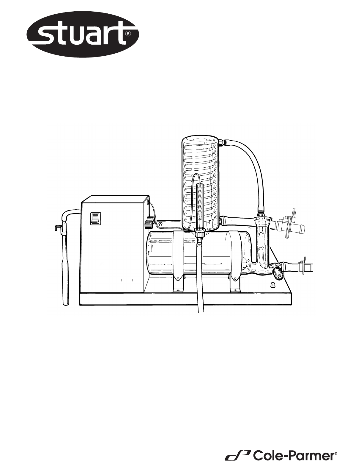
Distinction Water Still
D4000 & D4000/EURO
Instruction Manual
Manuel d’utilisation
700596 / 03 2017
water still Distinction D4000
ON
OFF
2
Before use
If the equipment is not used in the manner described in this
manual the protection provided by the equipment may be
impaired.
N.B. The Distinction Water Still is classified as “Permanently
Connected Equipment” and should be connected to the
electricity supply by a qualified electrician in the manner
described in the electrical installation section of this manual.
The Distinction Water Still is designed to operate under the
following conditions:
❖ For indoor use only
❖ Ambient temperature range +5°C to +40°C
❖ Altitude up to 2000m
❖ Relative humidity not exceeding 80%
❖ Mains supply voltage fluctuations not greater than
±10% of nominal
❖ Overvoltage category II IEC60364-4-443
❖ Pollution degree 2 IEC664
Distinction Water Still
D4000 & D4000/Euro
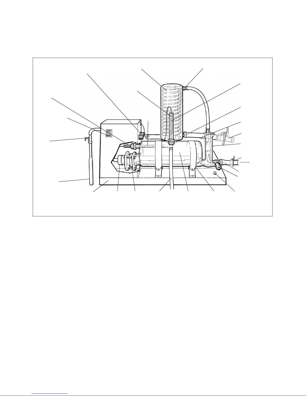
Figure 1 General assembly
Thermostat reset buttons
Boiler
thermostat
tube
On/Off switch
Clip
Reservoir
level
control
Heater Gaskets
and flange
Distillate
outlet tube
Boiler
Stand
Stopcock
To drain
Constant
level control
Wall mounting
screw holes
Condenser
cooling water
inlet
Condenser
thermostat tube
Condenser
outlet (upper)
Straps
Condenser
Condenser
thermostat
Boiler
thermostat
probe
ON
OFF
water still Dis
Hose assembly 2
Hose assembly 1
Outlet
Earth point for
earthed pipe straps

3
2. Remove the end cover from the electrical compartment by
undoing the retaining screws in the left hand panel.
3. Take the metal stand and place in the desired location. Note
that 2 screw holes are provided for wall mounting.
If wall mounting you must ensure you use appropriate
wall fixings that can hold a minimum weight of 80KG. If
you are in any doubt seek professional advice.
4. Take the boiler, the heater and the gasket kit and assemble as
shown in figure 2.
i) Place the bolts through the metal flange in the manner
shown and then place the metal flange over the tapered
glass tube of the boiler.
ii) Take the plastic insert and bend it round the glass tube
and into the metal flange. Pull the flange and insert
towards the open end of the glass tube until the insert
presses on the glass.
iii) Place the aluminium plate, followed by the silicone ring
over the heating element and locate approximately
40-45mm from the end with the electric cable, see fig. 2.
iv) Insert the heating element through the tapered glass tube
and into the boiler – ensure that there is clearance at the
inside end and no danger of the end of the element
pressing against the end of the boiler.
v) Insert the three bolts into the threaded holes in the
aluminium plate and evenly tighten. Check element is
secure and horizontal but do not over tighten bolts.
vi) Ensure the heating element is horizontal within the boiler
5. Take the two metal straps and attach the springs to the rear of
the “cradles” on the stand. Place the assembled boiler and
element onto the “cradle” of the stand. Slide the assembly
along until the protruding end of the element is located inside
the electrical compartment.
N.B. A “pip” on the bottom of the boiler locates in a hole in
the right-hand cradle.
Ensure that the boiler thermostat probe is located in the
thermostat tube.
Attach the free ends of the straps to the front of the cradle to
secure the boiler in place.
Location
The Distinction Water Still can be wall or bench mounted. Select a
convenient location which has access to the following services:-
Electricity Supply
Before connection please ensure that the line supply is suitable. The
Distinction Water Still is available in two models, model no. D4000
for supplies rated at 3kW, 220-240V 50/60 Hz single phase and
model no. D4000/EURO for supplies rated at 3kW, 200-230V,
50/60Hz, single phase. All units should be connected to the mains
supply via a double pole 30mA RCD isolating circuit breaker rated at
15A
Water Supply
A cold water supply capable of providing a minimum flow rate of
60 l/hr.
Drain
A waste water drain located below the level of the Still so that the
drain pipe can fall away straight without kinks or bends, to allow an
unimpeded flow. All water supplies and drainage systems should be
properly earth bonded.
Reservoir
A distillate collection reservoir should be located beneath the Still.
Assembly
1. Unpack the Still and identify the following components:-
Qty. Component Catalogue No.
1 Support Stand 1 Boiler D4000/B
1 Condenser WC48/M2
1 Heating element D240H for D4000
D220H for D4000/EURO
1 Hose kit W4000/HK
1 Gasket kit D4000/GK
1 Boiler thermostat tube WTT48
1 Condenser thermostat tube A515414
2 Plastic connecting caps QC18/11
2 Silicone rubber rings QR18/7 and QR18/10
1 P.T.F.E washer QW18/7
1 Reservoir level control WLS
Figure 2 Heater and thermostat tube assembly
Heater
Aluminium
plate
Silicone
ring
Plastic
insert
Metal
flange
Bolts
Boiler
Screwcap
Tapered glass tube
Boiler
thermostat
tube
40-45mm
4
Identify the “condenser” thermostat and place the free end of
its probe into the thermostat tube. Carefully bend the capillary
to ensure that it does not obstruct access to the thermostat
reset buttons. - see figure 1.
13. Refer to fig. 3e. Connect the cooling water inlet of the
condenser to the connector of the 8mm bore hose of hose
assembly 2. Connect the free end of the earthed spigot of hose
assembly 2 to the cold water feed.
Select good quality tubing and secure all connections with hose
clips.
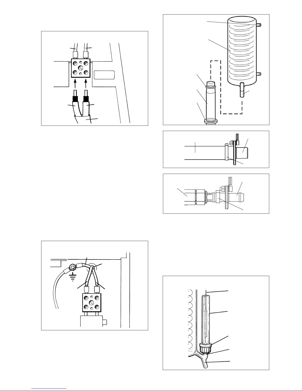
6. Connect the heater cable as shown in figure 3a.
- Push wires fully into block.
- Ensure screw terminations are tight.
7. Ensure that the sealing o-ring and stabilising o-ring are correctly
positioned, as shown in Figure 3c. Fit the condenser WC48/M2
by mounting it onto the vapour tube of the boiler. Ensure the
distillate outlet tube of the condenser faces the front and the
cooling outlet faces parallel to the unit.
8. From the hose kit take the length of 8mm bore hose fitted with
the plastic screwthread connectors at either end. Referring to
figure 1, screw one end of the hose to the condenser outlet
(upper) and the other end to the glass thread on the constant
level control.
09. Refer to fig. 3d. Carefully attach the end of the short 16mm
bore hose of hose assembly 1 to the outlet of the constant level
control. From the hose kit take the 1000mm length of 16mm
bore hose and attach to the free end of the earthed spigot. For
ease of connection, first warm the end of the hose with hot
water. Secure with the tie strap provided.
10. Lead the free end of the hose to drain, ensuring it falls away
from the Still with no kinks or bends to impede the water flow.
11. Ensure that the stopcock on the constant level control is closed.
12. Assemble the condenser thermostat tube A515414 connecting
cap QC18/11, silicone rubber ring QR18/7 as shown in figure 4a.
If the cap is left loose the assembly may now be carefully slid
over the air vent on the distillate outlet - see figure 4a.
Tighten up the cap once the tube is in place.
Figure 4a
Assembly of condenser thermostat tube
Condenser
thermostat
Condenser
thermostat
tube
Screwcap
Air vent
Distillate
outlet
Figure 3a
Heater electrical connections
Brown
Brown
Blue
Blue
Heater
cable
Heater
3kW 220/240V
Front
panel
Yellow/green
Mains
cable
Brown
Blue
N
L
Figure 3b
Figure 3c
Cooling water
outlet
Outlet
tube
Condenser
Sealing o-ring
Vapour tube
Stabilising o-ring
Figure 3d: Hose assembly 1
Connection to outlet of
constant level control
Free end
Tie-strap
Figure 3e: Hose assembly 2
Free end
Tie-strap
Connector
Mains electrical connections
5
14. Connect the distillate outlet of the condenser to a suitable
collection reservoir, using a suitable length of 9mm tubing.
A glass reservoir system is available from Cole-Parmer
(Catalogue No. WR20). Please contact the sales office for
details.
15. Replace the end panel on to the unit.
16. Take the reservoir control WLS and push the free end of the
rubber tubing onto the nozzle on the left hand end of the unit
- see figure 1.
Use the clip provided to mount the glass pressure bell in the
neck of the distillate reservoir.
Adjust the height of the pressure bell so that the open end is
approx. 140mm below the maximum distillate level.
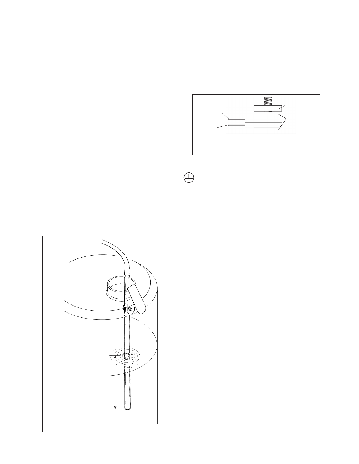
Fitting the Reservoir Control WLS to Collection Vessels
- Position the distillate collection reservoir in a suitable location.
This should be below the water still so that the vinyl rubber
tubing transporting the distilled water from the still can fall
down to the reservoir without restrictions, kinks or U bends.
- Take the Reservoir Level Control WLS and connect the free end
of the rubber tubing to the nozzle, of the reservoir pressure
switch located on the side of the stand.
- Use the metal clip to fit the glass pressure bell inside the
distillate collection reservoir. Refer to fig. 4b.
- Position the bell so that the open end is 140mm below the
desired distillate level.
17. Ensure that the earthed spigot wires are connected to the earth
point see fig 1.
18. Turn on the water supply to fill boiler and check for leaks then
turn off the water supply.
Fig 4b
WLS Reservoir level control
140mm
Electrical installation
THIS EQUIPMENT MUST BE EARTHED!
The electrical installation should be carried out by a qualified
electrician. The following method is recommended.
The earthed spigots should pass a high current (i.e. >200mA) earth
continuity test.
The equipment is supplied with 1.5m of PVC/PVC flexible, triple
core, circular cable with the following specification, 1.5mm
2
to BS
6500 or equivalent and <HAR> or BASEC approved.
The cable gland is designed to accept cable whose diameter is
>7.0mm and <10.5mm. It is recommended that, at the connection
to the mains electrical supply, there is fitted a 30mA RCD circuit
breaker with a continuous current carrying capacity of 15 amps at
250V, and rated at an overcurrent protection level of 15A . These
devices should be sited near to the equipment and be clearly marked
“Disconnect device for ‘Distinction’ Water Still”.
NOTE: Do not connect to electricity supply with a 13 amp
plug.
Cable connections are shown in figures 3a and 3b. Connect to the
line supply noting that the wires in the instrument lead are coloured
in accordance with the following code:
Blue - Neutral
Brown - Live
Green & Yellow - Earth
Mains Cable Replacement
If the mains cable requires replacement, only cable with the
specification given above should be used.
For live and neutral leads use bootlace crimps, size 1.5mm, with a
performance conforming to BS 4G178 part 1, 1984 and part 2,
1986.
For the earth lead use 1.5mm, M4 eyelet crimps with a performance
conforming to BS 4G178 part 1, 1984 and part 2, 1986. A suitable
crimp tool should be used.
Operation
1. Turn on the cold water supply and adjust the flow to approx. 60 l/
hr. Observe that the water flows via the condenser and into the
boiler. Wait until the boiler has attained its correct operating level
and make sure that the excess water is flowing freely to drain.
1. For hose assembly 1 follow fitting instruction 9.
2. Ensure that the earth wire is connected correctly to the earth
post - see figs 1 and 4c.
3. For hose assembly 2, please follow fitting instruction 13.
4. Ensure that the earth wire is connected to the earth post - see
figs. 1 and 4c.
Replacing earthed hose
assemblies
Hose
assembly 2
Figure 4c Earth post connection
Nut
Hose
assembly 1
Shake
proof
washers
 Loading...