

Page 1
Inhalt
Operating manual
Digital Transmitter DTM.OCS.S / DTM.OCS.S/N
Doc. No. 10.00.0430
Version: 01.11.2018
These operating instructions must be read by the operator before operation and installation!
Translation of the original operating manual
Page 2

2 Doc-Nr. 10.00.0430
Page 3

Operating manual Digital Transmitter DTM.OCS.S / DTM.OCS.S/N
Inhalt
Doc-Nr. 10.00.0430 3
1 Introduction ............................................................................ 6
1.1 Requirements/Basics ..................................................... 6
1.2 Abbreviations ................................................................. 6
1.3 Limitation of Liability ...................................................... 6
1.4 Copyright Protection ...................................................... 7
1.5 Spare Parts .................................................................... 7
1.6 Guarantee Provisions .................................................... 7
1.7 Customer Service .......................................................... 7
1.8 Registered Trademarks ................................................. 8
1.9 Reference Documentation ............................................. 8
2 Safety ...................................................................................... 9
2.1 Intended Use.................................................................. 9
2.2 Explanation of Symbols ................................................. 9
3 Product overview ................................................................. 10
4 Commissioning of the Digital Transmitter ........................ 11
4.1 Unpacking .................................................................... 11
4.2 Safety Notes ................................................................ 11
4.3 Notes on Installation .................................................... 11
4.4 Installation .................................................................... 12
5 Communication with the DTM.OCS.S transmitter ............ 13
5.1 Summary ...................................................................... 13
5.2 Physical interface ......................................................... 13
5.3 Software interface ........................................................ 13
5.3.1 Modbus ......................................................... 13
5.3.2 General Modbus message frame structure .. 14
5.4 Modbus STS commands ............................................. 14
5.4.1 STS command structure ............................... 14
5.4.2 Sensor response .......................................... 14
5.4.3 List of STS commands ................................. 15
5.4.3.1 MEASURE .................................... 15
5.4.3.2 Supported pressure units .............. 17
5.4.3.3 Supported temperature units ........ 18
5.4.3.4 GETPROBE .................................. 18
5.4.4 STS Modbus commands under the
magnifying glass ........................................... 19
Page 4

Operating manual Digital Transmitter DTM.OCS.S / DTM.OCS.S/N
Inhalt
4 Doc-Nr. 10.00.0430
6 Modbus standard commands .............................................21
6.1 Read pressure value (P) ..............................................21
6.1.1 Command (Hex-Code, Function Code 4) .....21
6.1.2 Interpretation start index 0: Measured
pressure value ..............................................21
6.2 Read temperature-value (T) .........................................21
6.2.1 Command (Hex-Code, Function Code 4) .....21
6.2.2 Interpretation start index 1: Measured
temperature value .........................................21
6.3 Read pressure and temperature in one command ......22
6.3.1 Command (Hex-Code, Function Code 4) .....22
6.4 Read maximum pressure (Nominal pressure, P
MAX
)....22
6.4.1 Command (Hex-Code, Function Code 3) .....22
6.4.2 Interpretation start index 200+201:
Nominal pressure..........................................22
6.5 Read minimal pressure (Zero-point pressure, P
MIN
) ....23
6.5.1 Command (Hex-Code, Function Code 3): ....23
6.5.2 Interpretation start index 202+203: Zero-
point pressure ...............................................23
6.6 Read maximum temperature (end of temperature
range, T
)..................................................................24
MAX
6.6.1 Command (Hex-Code, Function Code 3) .....24
6.6.2 Interpretation start index 204+205: End of
temperature range ........................................24
6.7 Read minimal temperature (start of temperature
range, T
) ..................................................................24
MIN
6.7.1 Command (Hex-Code, Function Code 3) .....24
6.7.2 Interpretation start index 206+207: Start of
temperature range ........................................24
6.8 Read P
MAX
, P
MIN
, T
MAX
, T
together in one
MIN
command .....................................................................24
6.8.1 Command (Hex-Code, Function Code 3) .....24
6.9 Change device’s Modbus address ...............................25
6.9.1 Command (Hex-Code, Function Code 16) ...25
6.10 Read serial number ......................................................25
6.10.1 Command (Hex-Code, Function Code 3) .....25
6.11 Read Firmware version ................................................25
6.11.1 Command (Hex-Code, Function Code 4) .....25
7 Technical Data ......................................................................27
8 Maintenance ..........................................................................28
8.1 Cleaning the Membrane ...............................................28
8.2 Recalibration ................................................................28
8.3 Disposal .......................................................................28
Page 5

Operating manual Digital Transmitter DTM.OCS.S / DTM.OCS.S/N
Inhalt
Doc-Nr. 10.00.0430 5
9 Troubleshooting ................................................................... 29
9.1 Error messages when using STS Modbus
commands ................................................................... 29
9.2 Error messages when using Modbus standard
commands ................................................................... 29
9.2.1 General ......................................................... 29
9.2.2 Exception codes ........................................... 29
10 Appendix ............................................................................... 30
10.1 Mapping of Modbus command codes .......................... 30
11 Revision history ................................................................... 31
Index .............................................................................................. 32
Page 6

Operating manual Digital Transmitter DTM.OCS.S / DTM.OCS.S/N
Introduction
Doc-Nr. 10.00.0430 6
Abbreviation
Meaning
DTM
Digital Transmitter
OCS
Open Communication System
P
Pressure
PZP
Zero-point pressure
PN
Nominal pressure
T
Temperature
DW
Data word
DB
Data byte
PDU
Protocol Data Unit
@
at
Tab. 1: Abbreviations
1 Introduction
1.1 Requirements/Basics
1.2 Abbreviations
You need basic knowledge of Modbus.
1.3 Limitation of Liability
All information and notes in these instructions have been put
together under consideration of the applicable standards and
provisions, the state of the art and our many years of insights and
experiences.
The manufacturer assumes no liability for damage due to:
Non-observation of these instructions
Non-intended use
Use of untrained staff
Unauthorized conversions
Technical changes
Use of unapproved spare and wear parts
The actual scope of delivery may deviate from the expectations
and illustrations here in special designs, utilization of additional
order options or due to the latest technical changes.
Apart from this, the obligations agreed on in the supply contract,
the general terms and conditions and the delivery conditions of the
manufacturer and the statutory rules applicable at the time of
conclusion of the contract shall apply.
Page 7
Operating manual Digital Transmitter DTM.OCS.S / DTM.OCS.S/N
Introduction
Doc-Nr. 10.00.0430 7
Warranty
The manufacturer guarantees for the function of the applied
process technology and the indicated performance parameters.
The warranty period shall commence at the time of delivery of the
device to the customer.
Components shall be excluded from the guarantee and claims for
defects if the damage has been caused by wear.
NOTE!
The content, texts, drawings, pictures and other
illustrations are copyright-protected and subject to
the commercial property rights. Any abusive
utilization is punishable.
ATTENTION!
Wrong or defective spare parts may cause
damage, malfunction or total failure.
Therefore:
→ Only use genuine spare parts of the
manufacturer.
1.4 Copyright Protection
The operating instructions must not be provided to any third parties
without the written consent of the manufacturer.
1.5 Spare Parts
1.6 Guarantee Provisions
Reproductions of any kind and form - even in excerpts - as well as
use and/or disclosure of the contents shall not be permitted without
written declaration of the manufacturer.
Purchase spare parts through the authorized dealer or directly from
the manufacturer. Address on the reverse.
For guarantee provisions, see "General terms and conditions".
1.7 Customer Service
Our customer service will be available for technical information.
Information on the relevant contact can be provided by phone, fax,
email or online at all times; see manufacturer's address on the last
page.
Page 8

Operating manual Digital Transmitter DTM.OCS.S / DTM.OCS.S/N
Introduction
8 Doc-Nr. 10.00.0430
1.8 Registered Trademarks
Any brand and product names are registered trademarks of the
respective companies and organizations.
1.9 Reference Documentation
MODBUS over Serial Line, Specification & Implementation
MODBUS Application Protocol Specification V1.1
STS Website
Guide V1.0
http://www.modbus.org
Modbus Standard Library section
http://www.modbus.org
Modbus Standard Library section
http://www.stssensors.com
Datasheets and general product information
Page 9
Operating manual Digital Transmitter DTM.OCS.S / DTM.OCS.S/N
Safety
Doc-Nr. 10.00.0430 9
The intended use of the Digital Transmitter DTM.OCS.S and
DTM.OCS.S/N is the measuring of pressure and temperature
and the transmitting of the values in real time to the interface
RS485 using Modbus RTU protocol.
Warning Notes
Warning notes are marked with symbols in these operating
instructions. The notes are preceded by signal words that
express the scope of the danger.
Comply with the notes and act with caution to avoid accidents,
injury and property damage.
ATTENTION!
… indicates a potentially dangerous situation that
may cause slight or minor injury if not avoided.
CAUTION!
… indicates a potentially dangerous situation that
may cause property damage if not avoided.
Advice and Recommendations
NOTE!
… highlights useful advice and recommendations,
as well as information for efficient and interferencefree operation.
2 Safety
2.1 Intended Use
The use in acids / bases is only possible to a limited extent.
Application and medium compatibility must be coordinated with
STS before commissioning or when ordering.
Only use the device as intended.
All information in the operating instructions must be complied with.
The operator shall be solely liable for any damage at non-intended
use.
2.2 Explanation of Symbols
Page 10
Operating manual Digital Transmitter DTM.OCS.S / DTM.OCS.S/N
Product overview
10 Doc-Nr. 10.00.0430
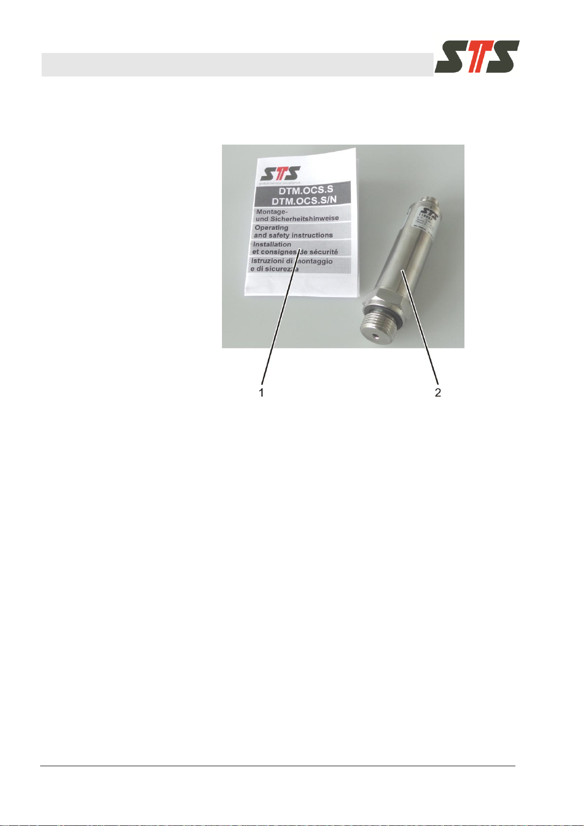
Fig. 1: Product overview Digital Transmitter DTM.OCS.S
1 Operating and safety instructions
2 Digital Transmitter
3 Product overview
The operating manual can be downloaded from the STS
homepage.
Page 11
Operating manual Digital Transmitter DTM.OCS.S / DTM.OCS.S/N
Commissioning of the Digital Transmitter
Doc-Nr. 10.00.0430 11
CAUTION!
Check the values on the rating plate, and
particularly the pressure range. These values must
correspond to the required technical data. The
seals are made of Viton (FPM), unless the order
confirmation states differently.
ATTENTION!
Have your device installed by specialists. Observe
the national safety provisions when installing and
operating the digital transmitter.
CAUTION!
Excessive vibrations, impact and pressure peaks
may falsify measurements and damage the digital
transmitter.
CAUTION!
Protect the digital transmitter from overload and
abrasion stress with titanium housing.
ATTENTION!
Connect the digital transmitter to depressurized
systems only.
Do not connect to systems under pressure!
4 Commissioning of the Digital Transmitter
4.1 Unpacking
The digital transmitter is delivered in product-specific packaging
that protects it outstandingly under regular transport conditions.
Check the packaging for outward damage. Take out the transmitter
carefully and without applying any force.
4.2 Safety Notes
4.3 Notes on Installation
Page 12
Operating manual Digital Transmitter DTM.OCS.S / DTM.OCS.S/N
Commissioning of the Digital Transmitter
12 Doc-Nr. 10.00.0430
NOTE!
Some digital transmitters are delivered with a
yellow protective cap for the pressure connection.
Remove the flap before you use the digital
transmitter.
CAUTION!
Ensure that the connection at the digital transmitter
is closed again carefully with the yellow protective
cap after disconnecting the cable from the digital
transmitter!
Do not connect the digital transmitter in the direct proximity of
motors, pumps, valves, heat sources or other possible
interference sources.
Protect the membranes from damage. Do not touch the
membranes.
Digital transmitter with cable output: Avoid damage to the cable
jacket. Observe the maximum permitted medium temperature of
the cable in the respective data sheet.
Do not kink/excessively bend the cable or route it over sharp
edges. Avoid abrasion points.
Reduce tension of the cable and the cable socket to the
minimum.
Observe the max. tightening torque of 30 Nm.
4.4 Installation
Refer to the instruction leaflet enclosed with the Digital Transmitter.
Page 13

Operating manual Digital Transmitter DTM.OCS.S / DTM.OCS.S/N
Communication with the DTM.OCS.S transmitter
Doc-Nr. 10.00.0430 13
Type
Setting
Transmission mode
Modbus RTU
Default address
24010
Transmission rate
9600 baud
Data bits
8
Parity
None
Stop bits
2
Tab. 2: Settings
5 Communication with the DTM.OCS.S transmitter
5.1 Summary
Communication with the DTM.OCS.S is accomplished via an
RS485 serial interface using Modbus protocol transfers at 9600
baud. STS specific, proprietary commands are transmitted as
ASCII strings embedded in Modbus compatible data frames.
Modbus standard function codes are supported as well.
The following settings apply:
5.2 Physical interface
For communication with the DTM.OCS.S, a suitable interface such
as a Modbus compatible RS485-USB converter must be employed.
5.3 Software interface
5.3.1 Modbus
Modbus is a master-slave communication protocol.
Slave devices will never communicate with each other.
Modbus telegrams in the RTU mode always begin with the
address (0 - 247) and a function code (FC Code). Then the data
words (DW) follows. 2 bytes with the CRC checksum form the
conclusion.
The function code indicates to the device what action to
perform.
Communication states (transmit/receive/cancel) are controlled
via timeouts.
The byte sequence for transmission of data words and the CRC
checksum is defined as follows:
Data words: Hi – Lo byte
CRC: Lo – Hi byte
For the communication with the DTM.OCS.S, standard Modbus
commands (Function Codes 3, 4 and 16) and a custom STS
function code (0x64 [10010]) are used.
Page 14
Operating manual Digital Transmitter DTM.OCS.S / DTM.OCS.S/N
Communication with the DTM.OCS.S transmitter
14 Doc-Nr. 10.00.0430
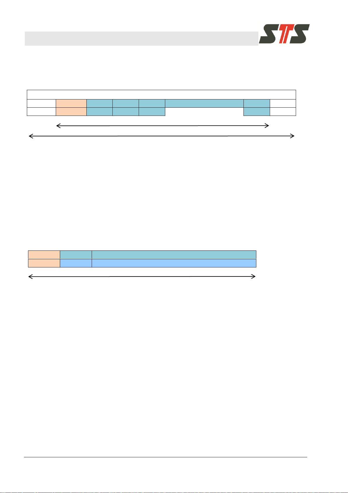
Modbus message (command or response)
Address
FC Code
DW1
DW2
DW3
………………………
DWn
CRC
1 byte
1 byte
2 bytes
2 bytes
2 bytes
2 bytes
2 bytes
Modbus PDU
Modbus Serial Line PDU
Tab. 3: Modbus message frame
FC Code
data size
STS command and its parameter(s) (ASCII encoded strings)
0x64
N
1 ≤ N ≤ 250 bytes
Modbus PDU
Tab. 4: STS command structure
5.3.2 General Modbus message frame structure
Message frame:
The number of data words can be derived from the definition of the
respective commands. The CRC checksum is divided into two
individual bytes with the low byte being transmitted first, followed
by the high byte. The CRC checksum is calculated using address,
function code and the data words. If the message is faulty (e.g. an
invalid CRC checksum is provided), no response is given.
5.4 Modbus STS commands
5.4.1 STS command structure
5.4.2 Sensor response
For the communication with the DTM.OCS.S, a custom STS
function code is used: 0x64 (10010).
The STS command and its parameter(s) are encoded as readable
ASCII text strings.
As they are embedded in the PDU’s payload field, the data frame
remains Modbus RTU compatible.
As required to be compliant with the Modbus standard, a sensor
response is carried out only upon a request from the master
device. The reply is embedded in the PDU’s payload, encoded as
readable ASCII text strings.
Provided a valid Modbus message frame was received, the reply
will contain the requested data, preceded by the received
command string (without parameters). Additionally, the
DTM.OCS.S returns one of the following status messages and
appends it to the requested data:
Page 15

Operating manual Digital Transmitter DTM.OCS.S / DTM.OCS.S/N
Communication with the DTM.OCS.S transmitter
Doc-Nr. 10.00.0430 15
Status message
Description
OK
Command has been executed successfully
FAIL
Command execution has been failed
BUSY
The device is busy, try again later
ERROR
Internal error
Tab. 5: Status messages
Parameter
Example
Exemplary answer
Description
(no
parameters)
MEASURE –P 2.9004 –PU
mH2O –T 27.6 –TU °C
reads out currently measured values
using default settings
2.9004 mH2O, 27.6 °C)
-PU
-PU mbar
MEASURE –P 284.44 –PU mbar
–T 27.6 –TU °C
returns the pressure in the requested
unit
284.44 mbar, 27.6 °C
-TU
-TU K
MEASURE –P 284.44 –PU mbar
–T 300.8 –TU K
returns the temperature in the
requested unit
284.44 mbar, 300.8 K
-UO
-UO 0.1
MEASURE –P 3.0004 –PU
mH2O –T 27.6 –TU °C
adds an offset to the measured
pressure value (the current default unit
is used)
3.0004 mH2O, 27.6 °C
-UG
-UG 2.0
MEASURE –P 5.8008 –PU
mH2O –T 27.6 –TU °C
multiplies the measured pressure value
UG times (the default unit is used)
NOTE! If a user offset (UO) is used then
the displayed pressure pd is calculated
as follows
(pm is the measured pressure value):
pd = UG × (pm + UO)
5.8008 mH2O, 27.6 °C
-TARE_V
-TARE_V 6.87
-
sets tare
6.87 mH2O
-DTW_V
-DTW_V 2.7
-
sets distance to water
2.7 mH2O
5.4.3 List of STS commands
For a detailed example please see chapter 5.4.4.
Listed below are the provided STS commands and their associated
parameters. Commands may be called with multiple parameters
combined.
5.4.3.1 MEASURE
The MEASURE command reads out the currently present pressure
and temperature.
Page 16

Operating manual Digital Transmitter DTM.OCS.S / DTM.OCS.S/N
Communication with the DTM.OCS.S transmitter
16 Doc-Nr. 10.00.0430
Parameter
Example
Exemplary answer
Description
-REF_V
-REF_V 0.45
-
sets the reference value tare and dtw
are referring to
0.45 mH2O
-SAVE
-SAVE
-
used to save the provided settings
NOTE! Provided settings will only be
saved permanently, if “-SAVE” is used
along with “magic number”.
-M
-M 1234567890
-
“magic number” used for permanently
saving the settings.
Tab. 6: MEASURE command parameters
Examples
Read out temperature but instead of returning the value in the
default unit, return it in Kelvin:
“MEASURE –TU K”
Change the default pressure unit to mWC:
“MEASURE -PU mWC -M 1234567890 -SAVE”
Set distance to water to 2.7 mWC and the reference value to 0.45:
“MEASURE -DTW_V 2.7 -REF_V 0.45 -M 1234567890 -SAVE“
Reset dtw and tare settings:
“MEASURE -DTW_V 0 –TARE_V 0 -REF_V 0 -M 1234567890
-SAVE“
Page 17
Operating manual Digital Transmitter DTM.OCS.S / DTM.OCS.S/N
Communication with the DTM.OCS.S transmitter
Doc-Nr. 10.00.0430 17
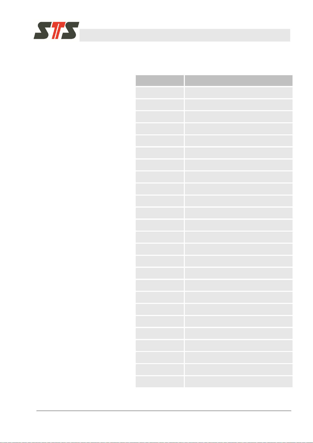
Unit
Description
mH2O
Meter of water column at 4 °C
cmH2O
Centimeter of water column at 4 °C
mmH2O
Millimeter of water column at 4 °C
ftH2O
Water column at 4 °C (in ft)
mWS
Meter of water column at 4 °C
mWK
Meter of water column at 4 °C
mWG
Meter of water column at 4 °C
mmWG
Millimeter of water column at 4 °C
inWG
Water column at 4 °C (in inches)
mWC
Meter of water column at 4 °C
mmWC
Millimeter of water column at 4 °C
inWC
Water column at 4 °C (in inches)
ftWC
Water column at 4 °C (in ft)
mNN
Meter of water column at 4 °C
mCE
Meter of water column at 4 °C
inHG
Mercury column (in inches)
mFC
Meter of fluid column
mmFC
Millimeter of fluid column
inFC
Fluid column (in inches)
mFG
Meter of fluid column
mmFG
Millimeter of fluid column
mbar
Millibar
bar
Bar
psi
Pound-force per square inch
Pa
Pascal
5.4.3.2 Supported pressure units
Page 18

Operating manual Digital Transmitter DTM.OCS.S / DTM.OCS.S/N
Communication with the DTM.OCS.S transmitter
18 Doc-Nr. 10.00.0430
Tab. 7: Pressure units
hPa
Hectopascal
kPa
Kilopascal
MPa
Megapascal
GPa
Gigapascal
N/m2
Newton per square meter
kN/m2
Kilonewton per square meter
MN/m2
Meganewton per square meter
GN/m2
Giganewton per square meter
N/mm2
Newton per square millimeter
kN/mm2
Kilonewton per square millimeter
Unit
Description
°C
Degree Celsius
°F
Degree Fahrenheit
K
Kelvin
Tab. 8: Temperature units
Parameter
Example
Exemplary answer
Description
-LIST
-LIST
GETPROBE -LIST “-CH” -CH0
Pressure -CH1 Temperature
lists the sensor’s available channels
Tab. 9: GETPROBE command parameters
5.4.3.3 Supported temperature units
5.4.3.4 GETPROBE
The GETPROBE command queries the available measurement
channels of the addressed sensor device.
Example
List the sensor’s available channels:
“GETPROBE -LIST”
Page 19
Operating manual Digital Transmitter DTM.OCS.S / DTM.OCS.S/N
Communication with the DTM.OCS.S transmitter
Doc-Nr. 10.00.0430 19
device
address
FC
code
data
size
------------------------- data --------------------------
--------- crc ---------
byte
code:
7B
64
07
4D
45
41
53
55
52
45
8A
B4
interpret
ation:
(7B16=123
10
)
‚M‘
‚E‘
‚A‘
‚S‘
‚U‘
‚R‘
‚E‘
CRC
low
CRC
high
transmit sequence
device address
FC code
data size
-------------------- data ---------------------
byte code:
7B
64
2F
4D
45
41
53
55
52
45
20
2D
interpretation:
(7B16=12310)
‚M‘
‚E‘
‚A‘
‚S‘
‚U‘
‚R‘
‚E‘
‚ ‘
‚-‘
transmit sequence
start of sequence
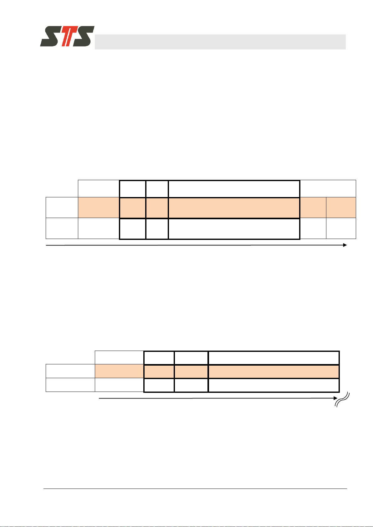
5.4.4 STS Modbus commands under the magnifying glass
Below a very detailed example including hex codes on a byte level
is presented to allow a more comprehensive understanding of the
command structure.
We use the command “MEASURE” (see chapter 5.4.3.1) as
illustrating example.
We assume the sensor address is 12310 and that its available
channels are pressure and temperature.
The following Modbus code must therefore be sent to the sensor
(numbers in hex format if not stated otherwise):
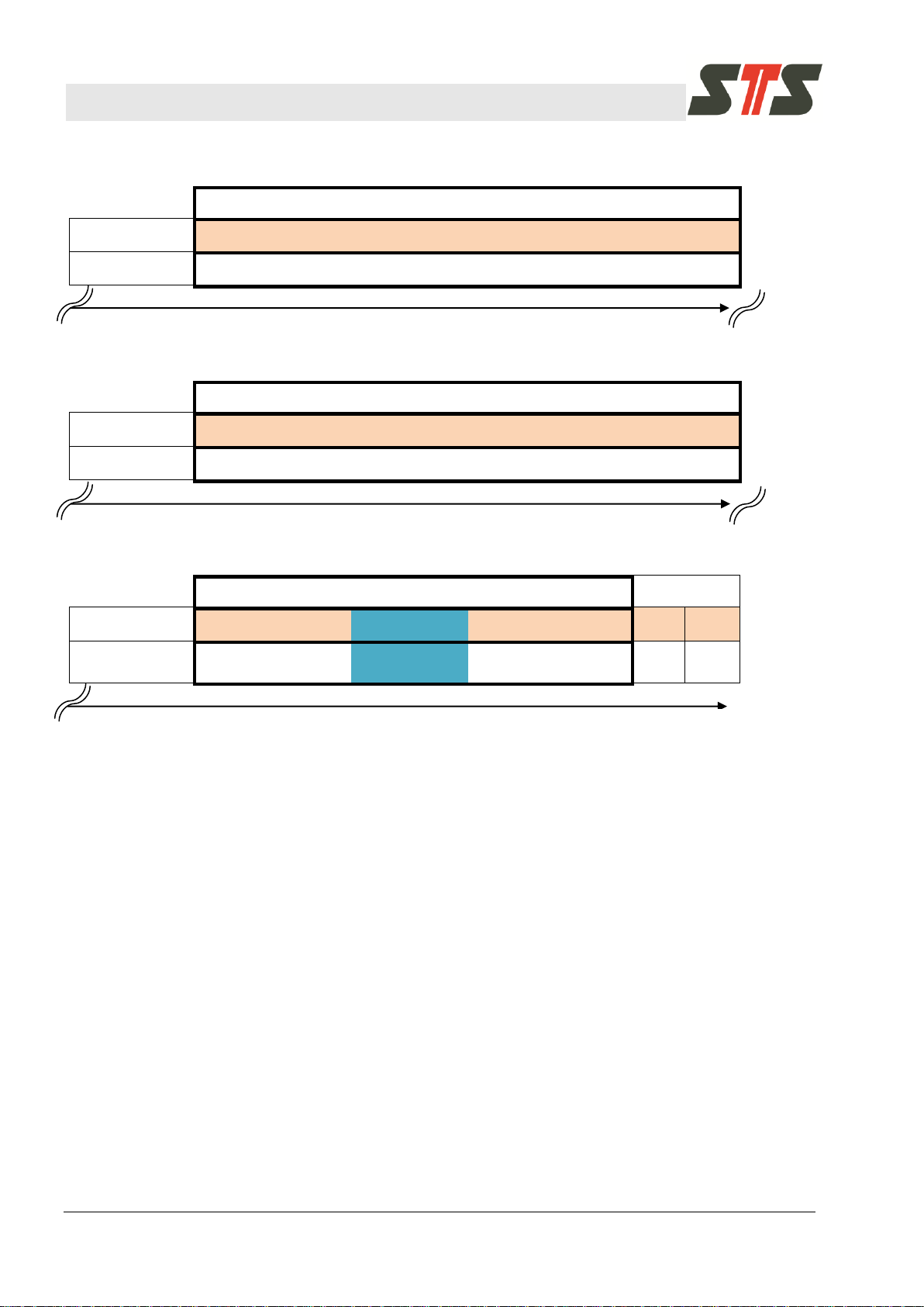
Now let’s say the sensor returns a pressure of 10.2500 mH2O and
a temperature of 27.2 °C.
The expected answer (embedded in the Modbus frame payload)
then would be:
“MEASURE -P 10.2500 -PU mH2O -T 27.2 -TU °C OK;”
Expressed as byte code this leads to:
Page 20
Operating manual Digital Transmitter DTM.OCS.S / DTM.OCS.S/N
Communication with the DTM.OCS.S transmitter
20 Doc-Nr. 10.00.0430
--------------------------------------------- data ---------------------------------------------
byte code:
50
20
31
30
2E
32
35
30
30
20
2D
50
55
interpretation:
‚P‘
‚ '
‚1‘
‚0‘
‚.‘
‚2'
‚5'
‚0'
‚0'
‚ '
‚-'
‚P'
‚U'
transmit sequence
--------------------------------------------- data ---------------------------------------------
byte code:
6D
48
32
4F
20
2D
54
20
32
37
2E
32
20
interpretation:
‚m‘
‚H'
‚2‘
‚O‘
‚ ‘
‚-'
‚T'
‚ '
‚2'
‚7'
‚.'
‚2'
‚ '
transmit sequence
----------------------------------- data -----------------------------------
----- crc -----
byte code:
2D
54
55
20
C2
B0
43
20
4F
4B
3B
40
39
interpretation:
‚-‘
‚T'
‚U‘
‚ ‘
‚C‘
‚ ‘
‚O‘
‚K‘
‚;‘
CRC
low
CRC
high
transmit sequence
end of sequence
Please note that UTF-8 encoding is used for the text strings. In the
example above this applies to the string “°C”, resulting in the byte
code 0xC2B043 (marked cyan).
Page 21

Operating manual Digital Transmitter DTM.OCS.S / DTM.OCS.S/N
Modbus standard commands
Doc-Nr. 10.00.0430 21
NOTE!
The following commands are all using the default
Modbus device address 240 (0xF0)!
]bar[P+
10000
])bar[P]bar[P(
*]sintpo[pressure=]bar[P
MIN
MINMAX
[°C]T+
10000
[°C])T[°C](T
*e[points]temperatur=T[°C]
MIN
MINMAX
6 Modbus standard commands
This chapter describes the Modbus standard command set
supported by the DTM.OCS.S. Function Codes 3, 4 and 16 are
used.
6.1 Read pressure value (P)
6.1.1 Command (Hex-Code, Function Code 4)
Example transmission code (in hex format) for a sensor with the
address 24010 (F016):
F0 04 00 00 00 01 24 EB
6.1.2 Interpretation start index 0: Measured pressure value
Pressure
Value range: 0 - 10,000 points
Conversion:
Value range: 16bit signed integer (-32,768…32,767), nominal
0…10,000 points (P
MIN…PMAX
).
6.2 Read temperature-value (T)
6.2.1 Command (Hex-Code, Function Code 4)
Example transmission code (in hex format) for a sensor with the
address 24010 (F016):
F0 04 00 01 00 01 75 2B
6.2.2 Interpretation start index 1: Measured temperature value
Temperature
Value range: 0 - 10,000 points
Conversion:
Value range: 16bit signed integer (-32,768…32,767), nominal
0…10,000 points (T
MIN…TMAX
)
Example transmission code (in hex format) for a sensor with the
address 24010 (F016)
Page 22
Operating manual Digital Transmitter DTM.OCS.S / DTM.OCS.S/N
Modbus standard commands
22 Doc-Nr. 10.00.0430
Address
Function
code
Start index
Length
crc
byte code:
F0
04
00
01
00
01
75
2B
format:
byte
byte
high byte
low byte
high byte
low byte
CRC
low
CRC
high
transmit sequence
Address
Function
code
ByteCount
Temperature [points]
crc
byte code:
F0
04
02
15
EF
8B
F9
format:
byte
byte
byte
high byte
low byte
CRC low
CRC high
transmit sequence
CT
69.23)10(
10000
))10(50(
*5615
T
= -10°C, T
MIN
= 50°C
MAX
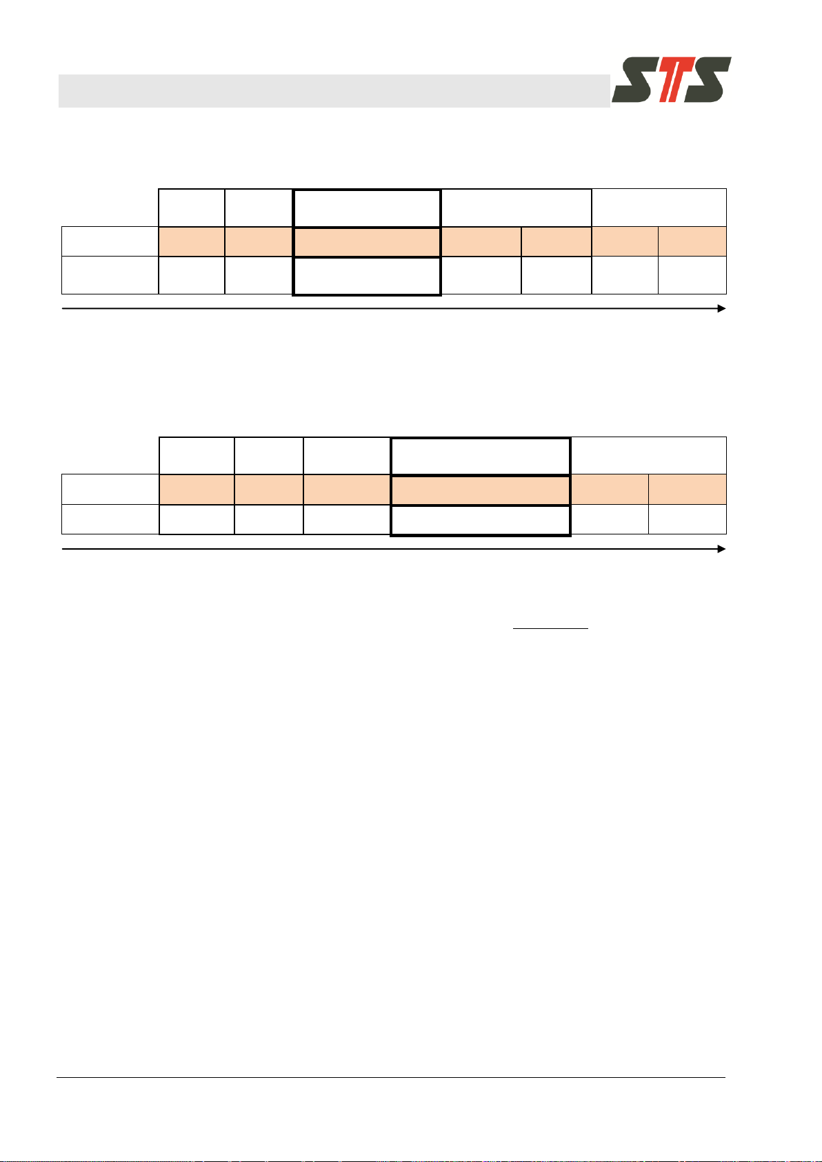
Example answer (in hex format) for a sensor with the address
24010 (F016).
Example conversion:
6.3 Read pressure and temperature in one command
6.3.1 Command (Hex-Code, Function Code 4)
Example transmission code (in hex format) for a sensor with the
address 24010 (F016):
F0 04 00 00 00 02 64 EA
6.4 Read maximum pressure (Nominal pressure, P
6.4.1 Command (Hex-Code, Function Code 3)
Example transmission code (in hex format) for a sensor with the
address 24010 (F016):
F0 03 00 C8 00 02 50 D4
6.4.2 Interpretation start index 200+201: Nominal pressure
Data type: 32 Bit signed integer
PMax1, PMax2
Description: Nominal pressure
MAX
)
Page 23

Operating manual Digital Transmitter DTM.OCS.S / DTM.OCS.S/N
Modbus standard commands
Doc-Nr. 10.00.0430 23
][
100000
][ bar
PMax
barP
MAX
][
100000
][ bar
PMin
barP
MIN
Calculation: P
= PMax2 * 65536 + PMax1
Max
If PMax > 231
PMax = (PMax2 * 65536 + PMax1) - 2
Example: PMax1 = 54464
PMax2 = 1
-> PMax = 120,000
-> P
= 1.2 bar
MAX
Calculation example: Return value is 0x27C00009:
PMax1 = 27C016 = 1017610 {low word}
PMax2 = 000916 = 9
10
PMax = 9*2^16 + 10176 = 600000 P
6.5 Read minimal pressure (Zero-point pressure, P
6.5.1 Command (Hex-Code, Function Code 3):
Example transmission code (in hex format) for a sensor with the
address 24010 (F016):
F0 03 00 CA 00 02 F1 14
MIN
{high word}
)
32
= 6.0 bar
MAX
6.5.2 Interpretation start index 202+203: Zero-point pressure
Data type: 32 bit signed integer
PMin1, PMin2
Description: Zero-point pressure
Calculation: PMin = PMin2 * 65536 + PMin1
If PMin > 231
PMin = (PMin2 * 65536 + PMin1) - 2
Example: PMin1 = 31072
PMin2 = 65534
-> PMin = -100,000
-> P
= -1 bar
MIN
32
Page 24

Operating manual Digital Transmitter DTM.OCS.S / DTM.OCS.S/N
Modbus standard commands
24 Doc-Nr. 10.00.0430
][
100000
][ C
TMax
CT
MAX
][
100000
][ C
TMin
CT
MIN
6.6 Read maximum temperature (end of temperature range, T
6.6.1 Command (Hex-Code, Function Code 3)
Example transmission code (in hex format) for a sensor with the
address 24010 (F016):
F0 03 00 CC 00 02 11 15
6.6.2 Interpretation start index 204+205: End of temperature range
Data type: 32 bit signed integer
TMax1, TMax2
Description: End of temperature range
Calculation: TMax = TMax2 * 65536 + TMax1
If TMax > 231
TMax = (TMax2 * 65536 + Tmax1) – 232
6.7 Read minimal temperature (start of temperature range, T
6.7.1 Command (Hex-Code, Function Code 3)
MAX
MIN
)
)
Example transmission code (in hex format) for a sensor with the
address 24010 (F016):
F0 03 00 CE 00 02 B0 D5
6.7.2 Interpretation start index 206+207: Start of temperature range
Data type: 32 bit signed integer
TMin1, TMin2
Description: Start of temperature range
Calculation: TMin = TMin2 * 65536 + TMin1
6.8 Read P
MAX
, P
MIN
, T
MAX
, T
If TMin > 231
TMin = (TMin2 * 65536 + TMin1) – 2
together in one command
MIN
32
6.8.1 Command (Hex-Code, Function Code 3)
Example transmission code (in hex format) for a sensor with the
address 24010 (F016):
F0 03 00 C8 00 08 D0 D3
Page 25

Operating manual Digital Transmitter DTM.OCS.S / DTM.OCS.S/N
Modbus standard commands
Doc-Nr. 10.00.0430 25
6.9 Change device’s Modbus address
6.9.1 Command (Hex-Code, Function Code 16)
Start index is 2010.
Example transmission code (in hex format) to change its address
from 24010 (F016) to address 22210 (DE16):
F0 10 00 14 00 01 02 00 DE 2C 88
Value range: 16bit unsigned integer (0...65536), nominal 1…247.
6.10 Read serial number
6.10.1 Command (Hex-Code, Function Code 3)
Start index is 21010.
Example transmission code (in hex format) for a sensor with the
address 24010 (F016):
F0 03 00 D2 00 02 71 13
Data type: 32 bit unsigned integer
SN1, SN2
Description: serial number of device, split-up into two 16 bit
values
Calculation: SN = SN2 * 65536 + SN1
Example answer (in hex format) for a sensor with the address
24010 (F016):
F0 03 04 6B 94 00 05 87 37
SN1 = 6B9416 = 2754010, SN2 = 000516 = 510
SN = 5*65536 + 27540 = 355220
6.11 Read Firmware version
6.11.1 Command (Hex-Code, Function Code 4)
Start index is 710.
Example transmission code (in hex format) for a sensor with the
address 24010 (F016):
F0 04 00 07 00 01 95 2A
Data type: 16 bit unsigned integer
Page 26

Operating manual Digital Transmitter DTM.OCS.S / DTM.OCS.S/N
Modbus standard commands
26 Doc-Nr. 10.00.0430
FWU16
Description: firmware version
Calculation: fw = FWU16/100
Example answer (in hex format) for a sensor with the address
24010 (F016):
F0 04 02 00 70 C5 01
FWU16 = 007016 = 11210
fw = 112/100 = 1.12
Page 27

Operating manual Digital Transmitter DTM.OCS.S / DTM.OCS.S/N
Technical Data
Doc-Nr. 10.00.0430 27
7 Technical Data
Refer to the data sheet of the Digital Transmitter DTM.OCS.S.
Page 28
Operating manual Digital Transmitter DTM.OCS.S / DTM.OCS.S/N
Maintenance
28 Doc-Nr. 10.00.0430
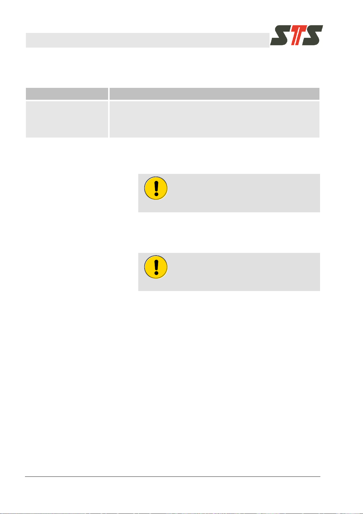
Interval
Maintenance work
Regularly, depending on the
medium that is monitored.
In case of uncertainty,
contact your STS distribution
partner.
Clean the membrane of the Digital Transmitter in case of strong pollution.
CAUTION!
Never use any pointy objects (e.g. screwdriver) to
clean the membrane! They may destroy the
membrane.
CAUTION!
Remove all plastic parts before descaling (seals,
safety cap). Do not use any further aids to remove
scale. Otherwise, the membrane may be damaged.
8 Maintenance
8.1 Cleaning the Membrane
8.2 Recalibration
Screw off the screw cap to expose the membrane.
Flush the membrane under running water. Ensure that the
membrane is not damaged.
In case of scale deposits, the membrane can be cleaned with
commercial descaler. Flush with running water after descaling.
In case of strong contamination, the membrane can also be
cleaned carefully with a cotton swab and liquid benzine. Ensure
that the membrane is not pushed in or damaged.
Return the digital transmitter to STS for recalibration.
8.3 Disposal
Return the digital transmitter to STS for disposal.
Page 29

Operating manual Digital Transmitter DTM.OCS.S / DTM.OCS.S/N
Troubleshooting
Doc-Nr. 10.00.0430 29
Fault
Possible cause
Troubleshooting
Digital Transmitter
responds with BUSY
The device is busy.
Try again later.
Digital Transmitter
responds with FAIL
The command execution has failed.
Faulty command.
Check correctness of command and
try again.
Digital Transmitter
responds with ERROR
Internal error of the device.
Disconnect the power supply from
the device for 10 seconds.
Reconnect and try again.
If this does not fix the error, contact
STS customer support.
Measurements are incorrect
or off
Sensor needs re-calibration.
Set an offset for the measurements.
If this does not fix the problem, send
the device back to STS.
Exception code
Fault description
1
The function code used in the command is not supported by the device.
2
a) The start index used in the command is not supported by the device.
b) The length used in the command is too big for the start index.
3
The length used in the command is 0.
4
a) Not enough rights (write/read) existent on an index used in the command
b) The value range of the data to be written is violated.
9 Troubleshooting
9.1 Error messages when using STS Modbus commands
9.2 Error messages when using Modbus standard commands
9.2.1 General
In Modbus Layer 7 protocol faulty accesses to a node are
answered by the node with an exception.
The exception response contains the original function code
increased by 128, followed by an exception code.
See chapter 9.2.2 for details.
For example: For a function code of 3, the exception answer is
received with a function code of 131. Following that is the
exception code.
With the exception code, an error in the receiver can be found out.
9.2.2 Exception codes
The following exception codes are possible:
Page 30

Operating manual Digital Transmitter DTM.OCS.S / DTM.OCS.S/N
Appendix
30 Doc-Nr. 10.00.0430
Value to get
Address
Format
Range
Description
Pressure
30001
Int16
-32768 ..
+32767
Pressure in %,
5660 equals 56.6%
Temperature
30002
Int16
-32768 ..
+32767
Temperature in %,
5660 equals 56.6%
Firmware Version
30008
Uint16
0 ..
+65536
Firmware version number
(multiplied by 100)
Modbus address
40021
Uint16
0 ..
+65536
Modbus address of device
(valid range: 1…247)
Max. pressure (P
MAX
)
40201
Int32
-2147483648
.. 2147483647
Maximal pressure (factory setting)
Min. pressure (P
MIN
)
40203
Int32
-2147483648
.. 2147483647
Minimal pressure (factory setting)
Max. temperature (T
MAX
)
40205
Int32
-2147483648
.. 2147483647
Maximal temperature (factory setting)
Min temperature (T
MIN
)
40207
Int32
-2147483648
.. 2147483647
Minimal temperature (factory setting)
Tab. 10: Mapping of Modbus command codes
10 Appendix
10.1 Mapping of Modbus command codes
Some Modbus implementations use a different way to address the
desired data fields. The following table might be of use in these
cases:
Page 31

Operating manual Digital Transmitter DTM.OCS.S / DTM.OCS.S/N
Revision history
Doc-Nr. 10.00.0430 31
Revision date
Chapter
Page
Change
Reason for change
01.11.2018
5.4.3.2
17
Supported pressure units
Extension of pressure units
11 Revision history
Page 32

Operating manual Digital Transmitter DTM.OCS.S / DTM.OCS.S/N
Index
Doc-Nr. 10.00.0430 32
Index
A
Abbreviations ........................................................6
C
Cleaning the membrane .................................... 28
Commissioning .................................................. 11
Communication with the DTM.OCS.S
transmitter ...................................................... 13
Contact ..................................................................7
Copyright protection ..............................................7
Customer service ..................................................7
D
Disposal ............................................................. 28
G
Guarantee .............................................................7
I
Installation
Digital Transmitter .......................................... 12
L
Liability ..................................................................6
M
Maintenance ...................................................... 28
Modbus command codes ................................... 30
Modbus standard commands ............................. 21
Modbus STS commands .................................... 14
P
Physical interface ............................................... 13
Product overview................................................ 10
Purpose ................................................................ 9
R
Recalibration ...................................................... 28
Registered trademarks ......................................... 8
Revision history .................................................. 31
S
Safety ................................................................... 9
Software interface .............................................. 13
Spare parts ........................................................... 7
STS commands.................................................. 15
Symbols
in the instructions ............................................. 9
T
Technical Data ................................................... 27
Troubleshooting ................................................. 29
W
Warranty ............................................................... 7
Page 33

Switzerland
Italy
STS Sensor Technik Sirnach AG
Rütihofstrasse 8
CH - 8370 Sirnach, Switzerland
Phone: +41 (0)71 969 49 29
Fax: +41 (0)71 969 49 20
E-Mail: [email protected]
Internet: www.stssensors.com
STS Italia s.r.l
Via Gesu 5
I - 20090 Opera (MI), Italy
Phone: +39 02 5760 7073
Fax: +39 02 5760 7110
E-Mail: [email protected]
Internet: www.stssensors.com
Germany
France
STS Sensoren Transmitter Systeme GmbH
Poststrasse 7
D - 71063 Sindelfingen, Germany
Phone: +49 (0)7031 204 9410
Fax: +49 (0)7031 204 9420
E-Mail: [email protected]
Internet: www.stssensors.com
STS France
844, Route de la Caille
FR-74350 Allonzier la Caille, France
Phone: +33 (0)450 08 48 15
Fax: +33 (0)450 67 02 43
E-Mail: [email protected]
Internet: www.stssensors.com
Great Britain
STS Great Britain Ltd
Warwick CV34 9AE
Box 3942
Great Britain
Phone: +44 (0)844 809 9927
E-Mail: [email protected]
Internet: www.stssensors.com
Companies of the STS Group
 Loading...