

Page 1
Power-PRO™ XT
6506
Operations Manual
2017/09 F.2 6506-209-001 REV F www.stryker.com
Page 2

sample text
Page 3
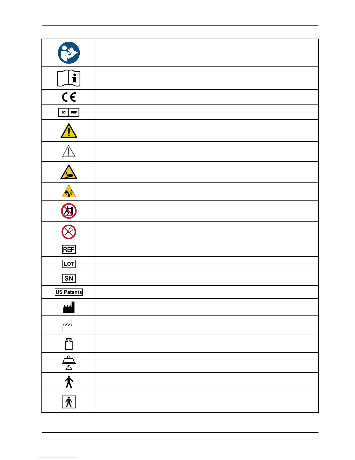
Symbols
Refer to instruction manual/booklet
Operating instructions
CE mark
European authorized representative
General warning
Caution
Warning; crushing of hands
Warning; non-ionizing radiation
No pushing
Do not lubricate
Catalogue number
Lot (batch) code
Serial number
For US Patents see www.stryker.com/patents
Manufacturer
Date of manufacture
Mass of equipment with safe working load
Safe working load
Type B applied part
Type BF applied part
www.stryker.com 6506-209-001 REV F
Page 4
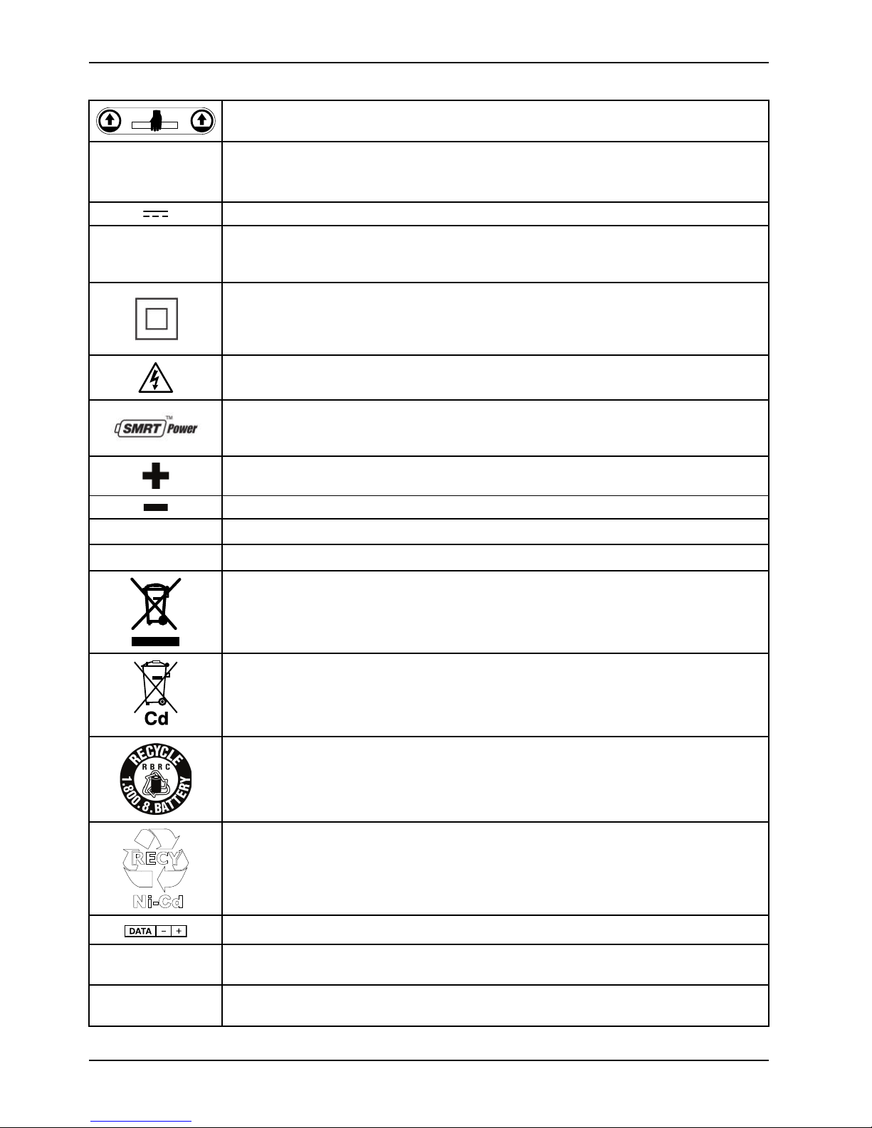
Symbols
~
Cd
DATA
_
+
Lift here
Medical Equipment Classified by Underwriters Laboratories Inc. With Respect to Electric Shock,
Fire, and Mechanical Hazards Only in Accordance with ANSI/AAMI ES60601-1:2012 and
CAN/CSA-C22.2 No. 60601-1:14.
Direct current
Alternating current
Class II electrical equipment: equipment in which protection against electric shock does not
rely on basic insulation only, but in which additional safety precautions such as double
insulation or reinforced insulation are provided, there being no provision for protective earthing
or reliance upon installation conditions.
Dangerous voltage
SMRT power system
IPX0
IPX6
Extend
Retract
Non-protected
Protection from powerful water jets
In accordance with European Directive 2002/96/EC on Waste Electrical and Electronic
Equipment, this symbol indicates that the product must not be disposed of as unsorted
municipal waste, but should be collected separately. Refer to your local distributor for return
and/or collection systems available in your country.
WEEE Directive (2012/96/EC). Contains cadmium.
The Rechargeable Battery Recycling Corporation (RBRC) is a non-profit, public service
organization that promotes the recycling of portable rechargeable batteries. Batteries must be
delivered to a battery collection site. Visit the RBRC website (www.rbrc.org) to find a nearby
collection site or call the phone number shown on the recycling symbol.
Contains nickel cadmium cells and should be recycled accordingly
Battery terminal identification (data line, negative, and positive)
KRX
23/44
2300 mAh
(1.2A/2h)
Ni-Cd cell identification per IEC 61951-1:20 03
Battery capacity, typical charge, and duration
6506-209-001 REV F www.stryker.com
Page 5
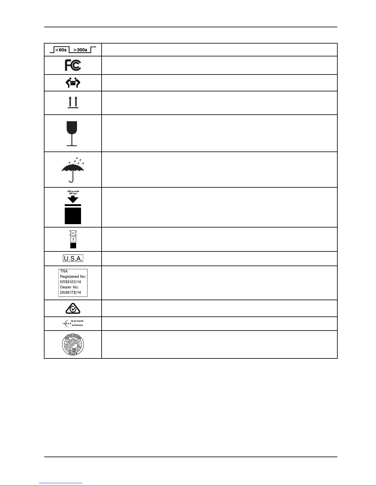
Symbols
< 60s > 300s
3
U.S.A.
TRA
Registered No:
ER35122/14
Dealer No:
DA35173/14
50
Cot duty cycle: 16.7% (less than 60 seconds on, more than 300 seconds off)
This device complies with Part 18 of the FCC rules
Two person lift
This way up
Fragile, handle with care
Keep dry
450 lb /205 kg weight capacity
Do not stack more than three high
English text below this symbol is intended for USA audiences only
Registered in United Arab Emirates by the Telecommunications Regulatory Authorities
Product complies with applicable EMC standards in Australia/New Zealand
Approved by independent communications authority of South Africa
Box manufacturer’s certificate - this packaging box has a minimum test value of 500 lb per sq.
in
www.stryker.com 6506-209-001 REV F
Page 6

sample text
Page 7

Table of Contents
Warning/Caution/Note Definition ...................................................................................................................4
Summary of safety precautions ....................................................................................................................5
Pinch points ....................................................................................................................................... 8
Mechanical stability .............................................................................................................................9
Introduction............................................................................................................................................ 11
Product description............................................................................................................................ 11
Indications for use ............................................................................................................................. 11
Expected service life .......................................................................................................................... 12
Contraindications............................................................................................................................... 12
Specifications - Power-PRO................................................................................................................. 12
Standards with required options............................................................................................................ 14
Specifications - SMRT ........................................................................................................................ 15
Product illustration - Power-PRO........................................................................................................... 16
Product illustration - SMRT .................................................................................................................. 17
Contact information............................................................................................................................ 17
Serial number location - Power-PRO...................................................................................................... 18
Serial number location - SMRT ............................................................................................................. 18
Date of manufacture .......................................................................................................................... 18
Setup.................................................................................................................................................... 19
Installation ............................................................................................................................................. 20
Installing the cot fastener .................................................................................................................... 20
Installing the in-fastener shut-off........................................................................................................... 20
Selecting the vehicle safety hook.......................................................................................................... 21
Vehicle configuration.......................................................................................................................... 22
Positioning of the vehicle safety hook, front to back .................................................................................. 23
Positioning of the vehicle safety hook, side to side .................................................................................... 24
Installing the vehicle safety hook........................................................................................................... 25
Operation .............................................................................................................................................. 27
Setting cot load height with jog function.................................................................................................. 27
Checking the battery power level .......................................................................................................... 27
Checking the hour meter and error display.............................................................................................. 28
Operating guidelines .......................................................................................................................... 29
Proper lifting techniques ..................................................................................................................... 29
Transferring the patient to the cot ......................................................................................................... 30
Rolling the cot with a patient ................................................................................................................ 30
Raising or lowering the cot................................................................................................................... 30
Raising, lowering, or releasing the cot with power ..................................................................................... 31
Raising or lowering the cot manually with the manual override..................................................................... 31
Expediting load with the high speed retract mode ..................................................................................... 32
Loading or unloading a cot with the Power-LOAD option............................................................................. 32
Loading a cot into a vehicle with an antler style cot fastener ....................................................................... 33
Unloading a cot from a vehicle with an antler style cot fastener ................................................................... 34
Positioning operators and helpers ......................................................................................................... 36
www.stryker.com 6506-209-001 REV F 1
Page 8

Table of Contents
Raising or lowering the backrest ........................................................................................................... 37
Raising or lowering the siderails ............................................................................................................ 37
Raising or lowering the siderails (XPS option) .......................................................................................... 37
Extending the retractable head section................................................................................................... 38
Retracting the retractable head section .................................................................................................. 38
Raising or lowering the footrest............................................................................................................. 39
Raising or lowering the optional knee gatch............................................................................................. 39
Applying or releasing a wheel lock......................................................................................................... 40
Applying or releasing the optional Steer-LOCK ......................................................................................... 40
Applying or releasing the optional kickstand for dialysis scale...................................................................... 40
Securing the patient with the G-rated restraint straps................................................................................. 41
Adjusting restraint straps ..................................................................................................................... 43
Securing a patient with the X-restraint/RUGGED™-X (6500-001-430/6506-001-430) restraint straps.................. 44
Adding a restraint strap extension ......................................................................................................... 47
Securing the patient with the Pedi-Mate® infant restraint system ................................................................. 48
Installing the child restraint with X-restraint package.................................................................................. 48
Installing the defibrillator platform.......................................................................................................... 50
Hanging equipment from the equipment hook .......................................................................................... 52
Installing the head extension with pillow.................................................................................................. 53
Positioning the two-stage IV pole........................................................................................................... 53
Positioning the optional three-stage IV pole ............................................................................................. 54
Attaching an oxygen bottle to the oxygen bottle holder............................................................................... 55
Attaching an oxygen bottle to the retractable head section oxygen bottle holder.............................................. 56
Installing the optional base storage net................................................................................................... 57
Installing the backrest storage pouch ..................................................................................................... 57
Installing the optional head end storage flat............................................................................................. 58
Transferring larger patients.................................................................................................................. 59
Attaching the mattress........................................................................................................................ 59
Installing a SMRT Pak ........................................................................................................................ 60
Removing a SMRT Pak from the cot ...................................................................................................... 60
Storing the battery ............................................................................................................................. 61
Charging the SMRT Pak...................................................................................................................... 61
Checking the SMRT Pak power level with the SMRT charger ...................................................................... 62
Electrical power installation requirements ............................................................................................... 63
Installing the SMRT charger................................................................................................................. 63
Installing the optional mounting bracket.................................................................................................. 63
Installing the charger onto the optional mounting bracket ........................................................................... 64
Powering the charger ......................................................................................................................... 65
Disconnecting the charger................................................................................................................... 66
Accessories ........................................................................................................................................... 67
Cleaning................................................................................................................................................ 68
Suggested cleaners........................................................................................................................... 68
Cleaning the charger.......................................................................................................................... 69
2 6506-209-001 REV F www.stryker.com
Page 9

Table of Contents
Cleaning the battery........................................................................................................................... 69
Preventive maintenance............................................................................................................................ 71
Lubrication....................................................................................................................................... 71
Regular inspection and adjustments ...................................................................................................... 71
Foot end fastener part replacement schedule.......................................................................................... 74
EMC information ..................................................................................................................................... 75
Warranty ............................................................................................................................................... 79
Warranty exclusion and damage limitations............................................................................................. 79
To obtain parts and service.................................................................................................................. 80
Return authorization........................................................................................................................... 80
Damaged product.............................................................................................................................. 80
International warranty clause ............................................................................................................... 80
www.stryker.com 6506-209-001 REV F 3
Page 10

Warning/Caution/Note Definition
The words WARNING, CAUTION , and NOTE carry special meanings and should be carefully reviewed.
WARNING
Alerts the reader about a situation which, if not avoided, could result in death or serious injury. It may also describe
potential serious adverse reactions and safety hazards.
CAUTION
Alerts the reader of a potentially hazardous situation which, if not avoided, may result in minor or moderate injury to the
user or patient or damage to the product or other property. This includes special care necessary for the safe and
effective use of the device and the care necessary to avoid damage to a device that may occur as a result of use or
misuse.
Note: Provides special information to make maintenance easier or important instructions clearer.
4 6506-209-001 REV F www.stryker.com
Page 11

Summary of safety precautions
Always read and strictly follow the warnings and cautions listed on this page. Service only by qualified personnel.
WARNING
• Always keep your hands clear of the red safety bar pivots when you load, unload, or change the height position of
the cot.
• Always use both hands when you transport the cot.
• Power-PRO with the Power-LOAD compatibility option operates primarily at these frequencies: 70 - 85 kHz for
inductive charging and 13.56 MHz±7 kHz, Amplitude Modulated (OOK), ERP: -82.37 dBm. The inductive charging
can operate between these frequencies: 70 - 125 kHz. Other equipment may interfere with the Power-LOAD system,
even if that other equipment complies with CISPR emission requirements.
• Always install the in-fastener shut-off system in any emergency vehicle that will be used with this cot if using an
antler style cot fastener.
• Install the cot fastener by qualified personnel only. Improper installation could result in injury to the patient or
operator.
• Always make sure that all cots meet the installation specifications for the Stryker cot fastener system.
• Always position the in-fastener shut-off before you place the cot into service.
• Do not attempt to operate the cot when it is loaded into a cot fastener.
• Always use the in-fastener shut-off to disable the electronic functionality only. Do not use the in-fastener shut-off for
any other purpose.
• Do not remove the battery when the cot is active.
• Always operate the cot only when all persons are clear of the mechanisms. Entanglement in powered cot
mechanisms can cause serious injury.
• Always inspect SMRT Paks for damage before every use.
• Do not allow untrained assistants to assist in the operation of the product.
• Do not ride on the base of the cot.
• Do not transport the cot sideways to avoid the risk of tipping. Always transport the cot in a lowered position, head end
or foot end first to minimize the risk of tipping.
• Always conduct patient monitoring when the cot is idle. If you hydraulically raise or lower the product you may
temporarily affect electronic patient monitoring equipment.
• Do not leave a patient unattended. Hold the product while a patient is on the product.
• Do not apply a wheel lock when a patient is on the product or when you move the product to avoid the risk of tipping.
• Do not use siderails as a patient restraint device.
• Always transport the cot at a lower height to reduce the risk of a cot tip. If possible, obtain additional assistance or
take an alternate route.
• Always avoid high obstacles, such as curbing, steps, or rough terrain to avoid the risk of the product tipping over.
• Always use Power-LOAD with the 6085/6086 Performance-PRO XT, 6500/6506 Power-PRO XT, and 6510/6516
Power-PRO IT cots with the Power-LOAD option only. In certain situations, you can use Power-LOAD as a standard
antler for most X-frame cots, but a rail clamp assembly is required for all cots without the Power-LO AD option.
• Always make sure that you use a Power-LOAD date of manufacture cot with the Stryker Model 6390 Power-LOAD
system to avoid the risk of injury.
• Always support the load of the patient, cot, and accessories after the weight is off of the ground.
• Do not pull or lift on the cot safety bar when you unload the cot.
• Always lock the head section into place before you operate the cot.
• Do not load the cot into a vehicle with the head section retracted when using a cot fastener. The cot may tip or not
connect with the cot fastener.
• Do not install or apply a wheel lock on a product with worn wheels that are less than 6 in. diameter.
www.stryker.com 6506-209-001 REV F 5
Page 12

Summary of safety precautions
WARNING (CONTINUED)
• Always use two people when using the kickstand.
• Always center the patient weight on the cot before you use the kickstand.
• Always apply the kickstand with your foot only.
• Always lower the cot height before you apply the kickstand for increased stability.
• Do not apply the kickstand during transport. Keep the kickstand in the retracted position.
• Do not use the kickstand as a brake.
• Do not apply the kickstand on a sloped surface.
• Always use all restraint straps to secure the patient on the cot. An unrestrained patient may fall from the cot.
• Do not attach restraint straps to the base tubes or cross tubes.
• Always use all restraint straps to secure the patient on the cot. An unrestrained patient may fall from the cot.
• Do not attach restraint straps to the base tubes or cross tubes.
• Always locate the buckle away from obstructions or accessories on the cot to avoid the risk of accidental release of
Pedi-Mate® infant restraint system and injury to the infant.
• Do not pinch your fingers between the fowler bracket and the oxygen bottle if your cot is equipped with the optional
retractable head section oxygen bottle holder.
• Do not remove the battery when the cot is activated.
• Do not attempt to open the battery pack for any reason, to avoid the risk of electric shock. If the battery pack case is
cracked or damaged, do not insert it into the charger. Return damaged battery packs to a service center for
recycling.
• Always avoid direct contact with a wet battery or battery enclosures. Contact may cause injury to the patient or
operator.
• Do not insert a cracked or damaged SMRT Pak into the SMRT charger. Return damaged SMRT Paks to a service
center for recycling.
• Always have a certified mechanic, familiar with ambulance vehicle construction, install the optional mounting bracket
and the SMRT charger.
• Always mount the SMRT charger to the optional mounting bracket in an enclosed cabinet and out of patient reach
during transport to comply with established crash test standards.
• Always make sure that the optional mounting bracket is securely attached to the surface.
• Always use any appropriate personal protective equipment while power washing to avoid inhaling contagion. Power
washing equipment may aerate contamination.
• Always wipe the product with clean water and dry after cleaning. Some cleaning products are corrosive in nature and
may cause damage to the product. Failure to properly rinse and dry the product leaves a corrosive residue on the
surface of the product and may cause premature corrosion of critical components.
• Always wear insulated rubber gloves, in addition to personal protective equipment, when cleaning the SMRT Pak to
reduce the risk of injury.
• Always disconnect the SMRT charger from the wall outlet before cleaning to avoid the risk of electrical hazards.
• Do not spray fluid directly onto the SMRT charger.
• Do not power wash the SMRT charger.
• Do not immerse the SMRT charger in water or allow water to collect on top of the SMRT charger to avoid the risk of
electric shock.
• Always use only non-conductive materials to wipe the SMRT Pak.
• Always refer to the disinfectant’s Material Safety Data Sheet (MSDS) to verify the pH range. Disinfectants with pH
levels higher than 10.5 may cause the SMRT Pak housing material to crack.
6 6506-209-001 REV F www.stryker.com
Page 13
Summary of safety precautions
WARNING (CONTINUED)
• Do not directly handle or make contact with the SMRT Pak terminals while cleaning to avoid the risk of injury.
• Do not immerse the SMRT Pak in liquid to reduce the risk of electric shock.
• Do not use solvents, lubricants, or other chemicals to clean the SMRT Pak unless otherwise directed.
• Always relieve pressure before you disconnect hydraulic or other lines. Escaping fluid under pressure can penetrate
the skin and cause serious injury. Tighten all connections before you apply pressure. If an accident occurs, see a
doctor immediately.
• Do not use bare hands to check for hydraulic leaks.
CAUTION
• Improper usage of the product can cause injury to the patient or operator. Operate the product only as described in
this manual.
• Do not modify the product or any components of the product. Modifying the product can cause unpredictable
operation resulting in injury to patient or operator. Modifying the product also voids its warranty.
• This equipment has been tested and found to comply with the limits for a Class A digital device, pursuant to part 15
of the FCC Rules. These limits are designed to provide reasonable protection against harmful interference when the
equipment is operated in a commercial environment. This equipment generates, uses, and can radiate radio
frequency energy and, if not installed and used in accordance with the instruction manual, may cause harmful
interference to radio communications. Operation of this equipment in a residential area is likely to cause harmful
interference in which case the user will be required to correct the interference at their expense.
• Always set the cot load height to the proper stop height before operation.
• Always have a certified mechanic, familiar with ambulance vehicle construction, install the vehicle safety hook.
Consult the vehicle manufacturer before you install the vehicle safety hook. Make sure that the installation of the
vehicle safety hook does not damage or interfere with the brake lines, oxygen lines, fuel lines, fuel tank, or electrical
wiring of the vehicle.
• Always charge the battery before you place the product into service. An uncharged or depleted battery may cause
poor product performance.
• Always clear any obstacles that may interfere and cause injury to the operator or patient before operating the
product.
• Do not entangle the restraint straps in the base frame when you raise or lower the cot.
• Always secure the defibrillator platform to the product when you use the defibrillator platform.
• Always use and adjust the straps that are provided with the defibrillator platform to secure the defibrillator.
• Always change the installation location or adjust the straps for your specific defibrillator size or shape.
• Do not load the defibrillator platform above the safe working load of 30 lb (13.6 kg).
• Do not load the equipment hook above the safe working load of 35 lb (15.8 kg).
• Always remove all accessories or equipment from the equipment hook when in the vehicle.
• Do not load the oxygen bottle holder above the safe working load of 15 lb (6.8 kg).
• Do not use two oxygen bottle holders at the same time.
• Do not load the backrest storage pouch above the safe working load of 20 lb (9 kg).
• Do not allow the storage pouch to interfere with the operation of the retractable head section.
• Always remove the battery if the cot is not going to be used for an extended period of time (more than 24 hours).
• Always place the electrical SMRT charger power cord where it will not be stepped on, tripped over, or otherwise
subjected to damage or stress.
• Do not touch the SMRT Pak receptacle terminals with metal objects.
www.stryker.com 6506-209-001 REV F 7
Page 14
Summary of safety precautions
CAUTION (CONTINUED)
• Always grasp and pull the plug, not the cord, when you disconnect the SMRT charger to avoid the risk of damage to
the electrical plug and cord.
• Do not steam clean or ultrasonically clean the product.
• Do not exceed 180 °F (82 °C) as the maximum water temperature.
• Do not exceed 1500 psi (130.5 bar) as the maximum water pressure. If you are using a hand held wand to wash the
product, keep the pressure nozzle at a minimum of 24 in. (61 cm) from the product.
• Always allow to air dry.
• Always remove the battery before you wash the cot.
• Do not clean, service, or perform maintenance while the product is in use.
• Do not steam clean or ultrasonically clean the SMRT Pak.
• Always use authorized parts to avoid the risk of product damage.
• Always check hoses and lines regularly to avoid damage to the cot. Check and tighten loose connections. Hydraulic
lines, hoses, and connections can fail or loosen due to physical damage, kinks, age, and environment exposure.
• Do not tip the cot onto its load wheels and actuate the product as this will allow air to enter the hydraulic system.
• The use of accessories, transducers, and cables, other than those specified or provided by the manufacturer, could
result in increased electromagnetic emissions or decreased electromagnetic immunity and result in improper
operation.
• The emissions characteristics of this equipment make it suitable for use in industrial areas and hospitals (CISPR 11
class A). If it is used in a residential environment, for which CISPR 11 class B is normally required, this equipment
might not offer adequate protection to radio frequency communication services. The user might need to take
mitigation measures, such as relocating or reorienting the equipment.
• Avoid stacking or placing other equipment adjacent to Power-PRO and SMRT charger to prevent improper operation
of the products. If such use is necessary, carefully observe Power-PRO and SMRT charger and the other equipment
to make sure that they are operating properly.
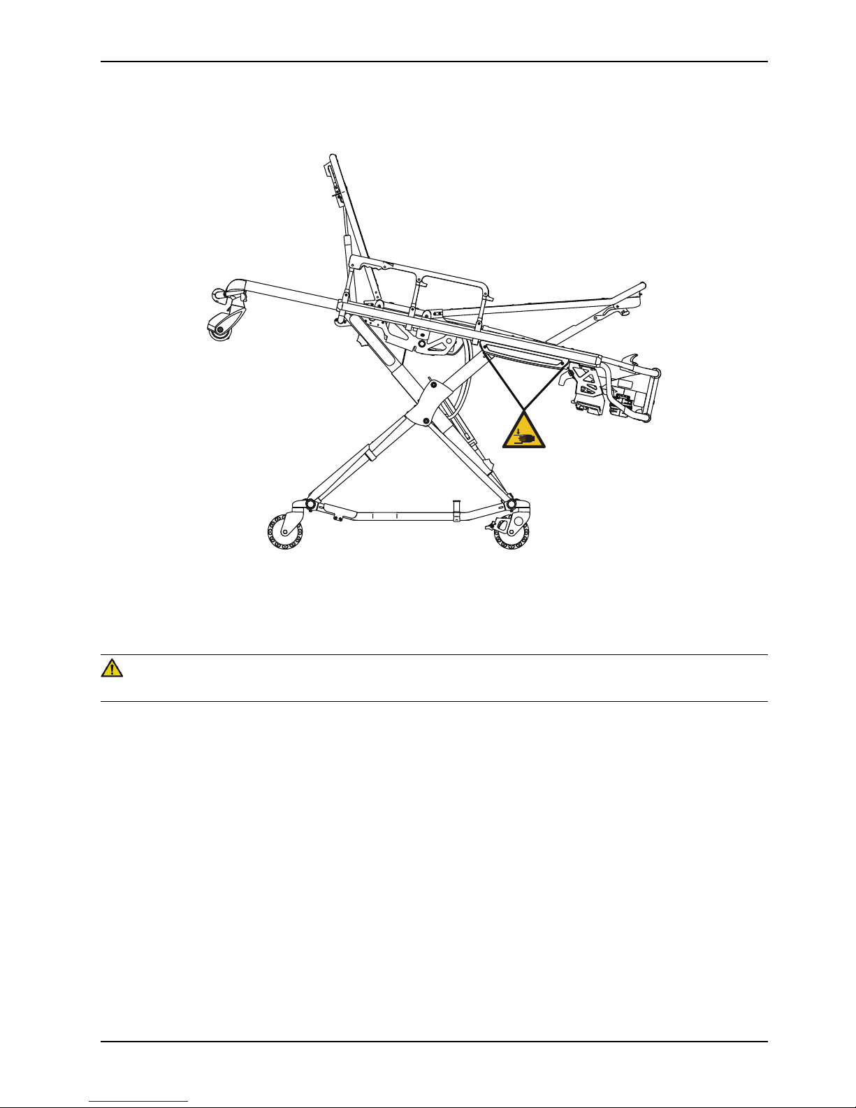
Pinch points
WARNING
Always keep your hands clear of the red safety bar pivots when you load, unload, or change the height position of the cot.
8 6506-209-001 REV F www.stryker.com
Page 15
Summary of safety precautions
Pinch points (Continued)
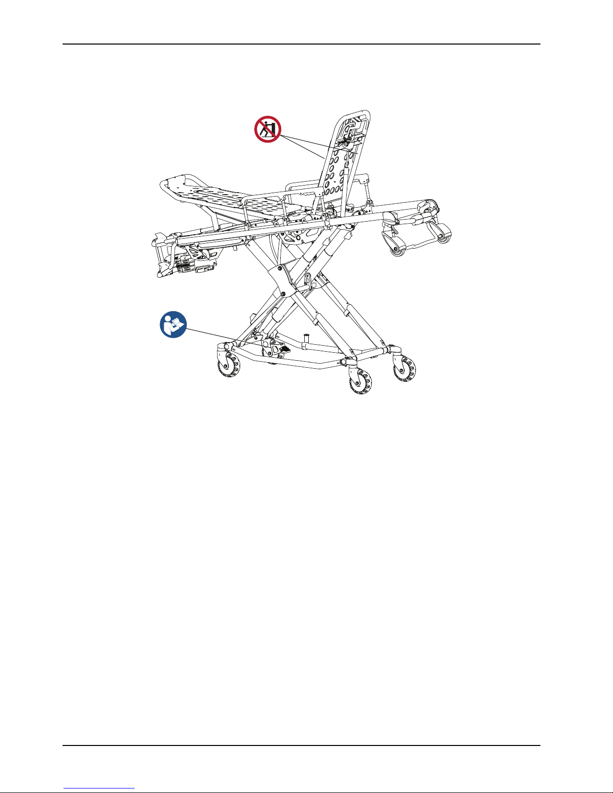
Mechanical stability
WARNING
Always use both hands when you transport the cot.
Figure 1: Pinch points
www.stryker.com 6506-209-001 REV F 9
Page 16
Summary of safety precautions
Mechanical stability (Continued)
Figure 2: Mechanical stability
Notes
• If the cot is on a plane steeper than five degrees, place the cot in the lowest position.
• Do not use the defibrillator option and the foot end oxygen bottle holder option at the same time.
10 6506-209-001 REV F www.stryker.com
Page 17

Introduction
This manual assists you with the operation or maintenance of your Stryker product. Read this manual before operating or
maintaining this product. Set methods and procedures to educate and train your staff on the safe operation or
maintenance of this product.
CAUTION
• Improper usage of the product can cause injury to the patient or operator. Operate the product only as described in
this manual.
• Do not modify the product or any components of the product. Modifying the product can cause unpredictable
operation resulting in injury to patient or operator. Modifying the product also voids its warranty.
Notes
• This manual is a permanent part of the product and should remain with the product even if the product is sold.
• Stryker continually seeks advancements in product design and quality. This manual contains the most current
product information available at the time of printing. There may be minor discrepancies between your product and
this manual. If you have any questions, contact Stryker Customer Service or Technical Support at 1-800-327-0770.
Product description
The Stryker Model 6506 Power-PRO™ XT cot is a powered ambulance cot that consists of a platform mounted on a
wheeled X-frame designed to support and transport a maximum weight of 700 lb (318 kg) in pre-hospital and hospital
environments.
The device is collapsible for use in emergency vehicles and has an adjustable load height feature to allow the device to
be set to different ambulance deck heights for proper body mechanics during loading and unloading. The NiCd batterypowered hydraulic lift system allows operators to raise and lower the cot using the powered controls, while duplicate footend controls on the upper and lower lift bars accommodate different operator positions or sizes. The cot is equipped with
a manual back-up release handle to allow the operation of cot functions in the event of power loss. The device is
equipped with a retractable head section for 360-degree mobility in any height position, side rails, patient securement
straps, an adjustable pneumatic backrest, and various optional accessories that assist with the transport of a patient.
Maximum patient comfort is attainable with the three different litter positions of shock, flat leg, and optional knee gatch
positioning.
The SMRT™ power system consists of a SMRT charger and a SMRT Pak. The SMRT Pak powers the hydraulic lift
system of the Stryker powered ambulance cots.
Indications for use
The Stryker Power-PRO XT is a powered wheeled stretcher, which is intended to support and transport the entire body of
a traumatized, ambulatory, or non-ambulatory human patient (includes infants and adults).
The battery-powered hydraulic lift system is intended to help reduce the effort required by the operator to raise and lower
the cot. The device is designed to support patients in a supine (horizontal) or sitting position and facilitate the
transportation of associated medical equipment (such as oxygen bottles, monitors, or pumps) in emergency or transport
vehicles. This ambulance cot is intended to be used in pre-hospital and hospital environments, and in emergency and nonemergency applications. It is rated to a maximum capacity of 700 lb (318 kg) (sum of the patient, mattress, and
accessory weight) and the intended operators of the device are trained professionals including emergency medical
service and medical care center personnel, as well as medical first responders.
Power-PRO XT is not intended for extended stay or use as a hospital bed or in devices that modify air pressure, such as
hyperbaric chambers.
www.stryker.com 6506-209-001 REV F 11
Page 18

Introduction
Expected service life
Power-PRO has a seven year expected service life under normal use conditions and with appropriate periodic
maintenance.
The SMRT charger has a seven year expected service life under normal use conditions and with appropriate periodic
maintenance.
The SMRT Pak battery has a two year expected service life under normal use conditions.
Contraindications
None known.
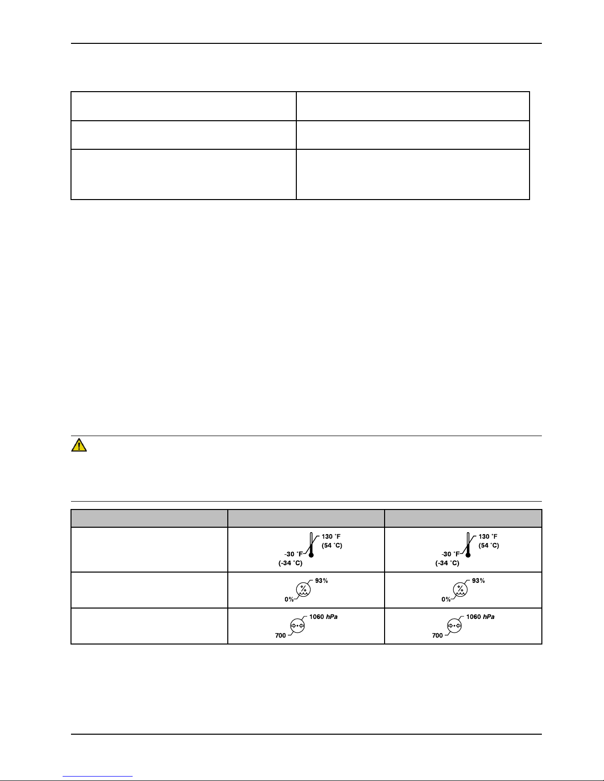
Specifications - Power-PRO
Safe working load
Note: Safe working load indicates
the sum of the patient, mattress,
and accessory weight.
Maximum unassisted lift capacity
Backrest articulation/shock position (standard fowler 6506-012-003)
Backrest articulation/shock position (1865 fowler
option - 6506-012-004)
Backrest articulation/shock position (6506-700-013) 6° to 73°/+15°
Overall length/minimum length/width
2
Height
Weight
Caster diameter/width
Minimum operators required for loading/ unloading an
occupied cot
Minimum operators required for loading/ unloading an
unoccupied cot
3
1
700 lb 318 kg
500 lb 227 kg
0° to 73°/+15°
0° to 75°/+15°
81 in./63 in./23 in. 206 cm/160 cm/58 cm
Adjustable from 14 in. to
41.5 in.
125 lb 57 kg
6 in./2 in. 15 cm/5 cm
2
1
Adjustable from 36 cm to
105 cm
Recommended fastener systems
Recommended loading height
Recommended working height (excluding mattress) 15.75 in. 40 cm
Hydraulic oil
Power system
Battery 24 VDC NiCd - SMRT power system
12 6506-209-001 REV F www.stryker.com
4
Model 6370 or 6377 Floor mount type, Model 6371 Wall
mount type, Model 6390 Power-LOAD, Model 6392
Performance-LOAD
Up to 36 in. Up to 91 cm
Stryker part number 6500-001-293
Page 19
Introduction
130 °F
(54 °C)
-30 °F
(-34 °C)
130 °F
(54 °C)
-30 °F
(-34 °C)
93%0%93%
0%
1060 hPa
700
1060 hPa
700
Specifications - Power-PRO (Continued)
Charger 100-240 VAC 1.20 A,
50/60 Hz or 12 VAC 4.16 A - SMRT power system
Cot duty cycle 16.7% (less than 60 seconds on, more than 300 seconds
off)
Standards (cots and chargers) ANSI/AAMI ES60601-1: 2012, CAN/CSA-C22.2 No. 60601-
1:14, KKK-A-1822
For standards that require specific options, see
Standards with required options on page 14.
1
Cot loads over 300 lb (136 kg) may require additional assistance to meet the set cot load height.
2
Height measured from bottom of mattress at seat section to ground level.
3
Cot is weighed with one battery and without mattress and restraints.
4
Set the cot height to any ambulance deck height that ranges from 26 in. to 36 in. (66 cm to 91 cm).
Stryker reserves the right to change specifications without notice.
Power-PRO XT is designed to conform to the Federal Specification for the Star-of-Life Ambulance (KKK-A-1822 ).
Power-PRO XT is designed to be compatible with some competitive cot fastener systems.
The yellow and black color scheme is a proprietary trademark of Stryker Corporation.
Hereby, Stryker declares that the radio equipment type short range device is in compliance with Directive 2014/53/EU.
The full text of the EU declaration of conformity is available at the following internet address: http://techweb.med.
strykercorp.com/EMS/EU%20Declaration%20of%20Conformity/index.html.
Labels may be unreadable from a viewing distance greater than 12 inches.
WARNING
Power-PRO with the Power-LOAD compatibility option operates primarily at these frequencies: 70 - 85 kHz for inductive
charging and 13.56 MHz±7 kHz, Amplitude Modulated (OOK), ERP: -82.37 dBm. The inductive charging can operate
between these frequencies: 70 - 125 kHz. Other equipment may interfere with the Power-LOAD system, even if that
other equipment complies with CISPR emission requirements.
Environmental conditions
Temperature
Relative humidity
Atmospheric pressure
Operation Storage and transportation
www.stryker.com 6506-209-001 REV F 13
Page 20

Introduction
Specifications - Power-PRO (Continued)
CAUTION
This equipment has been tested and found to comply with the limits for a Class A digital device, pursuant to part 15 of the
FCC Rules. These limits are designed to provide reasonable protection against harmful interferen ce when the equipment
is operated in a commercial environment. This equipment generates, uses, and can radiate radio frequency energy and,
if not installed and used in accordance with the instruction manual, may cause harmful interferen ce to radio
communications. Operation of this equipment in a residential area is likely to cause harmful interference in which case
the user will be required to correct the interference at their expense.
Note: In accordance with the European REACH regulation and other environmental regulatory requirements, the 6500001-210 and 6500-001-211 hydraulic hoses contain dibutyl phthalate (DBP).
Standards with required options
To be compliant with the standards, you must install the following required options on your cot.
Note: Compatible cot is loaded into Power-LOAD in powered mode for crash testing.
Option selection
Standard
SAE J3027 crash-test
standards with the use of a
crash-rated fastener
AS/NZS-4535 crash-test
standards with the use of a
crash-rated fastener
BS EN 1789:2007+A2 :2014
crash-test standards with
the use of a crash-rated
fastener
BS EN 1865-3:2012
+A1:2015
BS EN 1865-2:2010
+A1:2015
Restraint package Mattress
X-restraint package (6500001-430) or RUGGED-X
restraint package (6506001-430)
X-restraint package (6500001-430)
G-rated restraint package
(6500-002-030), X-restraint
package (6500-001-430),
or RUGGED-X restraint
package (6506-001-430)
Knee gatch bolster
mattress (6500-002150/6506-002-150 ) or XPS
mattress (6500-003130/6506-003-130 )
(depending on cot siderail)
Knee gatch bolster
mattress (6500-002150/6506-002-150 ) or XPS
mattress (6500-003130/6506-003-130 )
(depending on cot siderail)
Knee gatch bolster
mattress (6500-002150/6506-002-150 ) or XPS
mattress (6500-003130/6506-003-130 )
(depending on cot siderail)
Option
XPS option (6506-040-000)
1865 fowler option (6506012-004)
The Britax Meridian SICT Series No. 7200/A/2010 Convertible Child Restraint with the X-restraint package (6500-001-
430) has been dynamically crash tested with a 10 kg crash dummy to 18.2 G forward and 10 G sideward per AS/NZS4535: 1999 crash-test standards.
14 6506-209-001 REV F www.stryker.com
Page 21
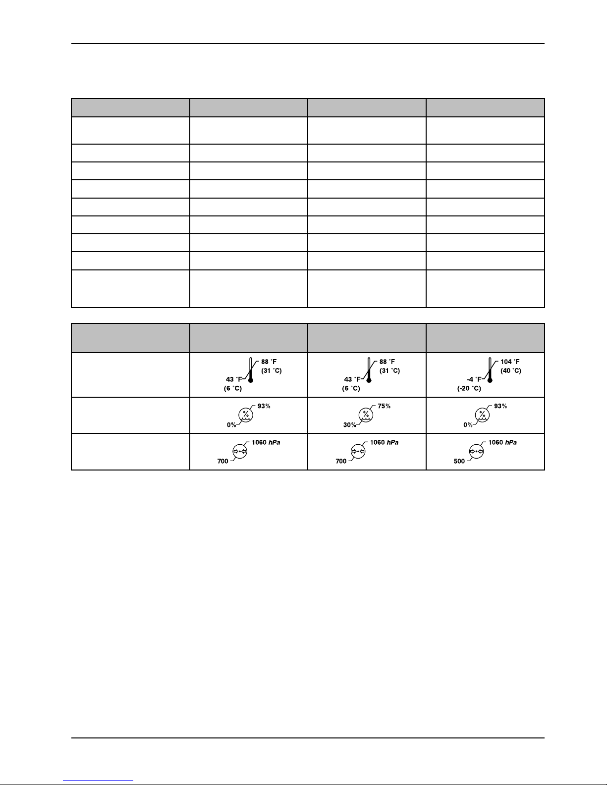
Specifications - SMRT
88 °F
(31 °C)
43 °F
(6 °C)
88 °F
(31 °C)
43 °F
(6 °C)
104 °F
(40 °C)
-4 °F
(-20 °C)
93%0%75%
30%
93%
0%
1060 hPa
700
1060 hPa
700
1060 hPa
500
Introduction
SMRT charger SMRT Pak AC power supply
Electrical input
13.9 VDC 4.16 A
Not applicable
100-240 VAC 1.20 A 50/60
Hz
Electrical output
Open circuit 40 VDC 1.20 A 24 VDC NiCd 12 VDC 4.16 A
Height 2.375 in. (60.325 mm) 3.25 in. (82.55 mm) 1.61 in. (40.89 mm)
Width 5.125 in. (130.175 mm) 4 in. (101.6 mm) 2.56 in. (65.02 mm)
Length 7 in. (177.8 mm) 5.75 in. (146.05 mm) 4.72 in. (119.89 mm)
Weight 1.3 lb (.59 kg) 3.8 lb (1.7 kg) .61 lb (.28 kg)
Enclosure protection IPX0 IPX6 IPX0
Equipment type Not applicable Not applicable
Approvals ANSI/AAMI ES60601-1:
Not applicable Not applicable
Class II
2012, CAN/CSA-C22.2 No.
60601-1:14
Environmental conditions
Operation Charging Storage and
transportation
Temperature
Relative
Atmospheric pressure
Specifications are approximate and may vary from unit to unit or as a result of power supply fluctuations.
Stryker reserves the right to change specifications without notice.
www.stryker.com 6506-209-001 REV F 15
Page 22
Product illustration - Power-PRO
A
B
C
D
E
F
G
H
I
K
L
M
N
O
P
Q
R
J
Introduction
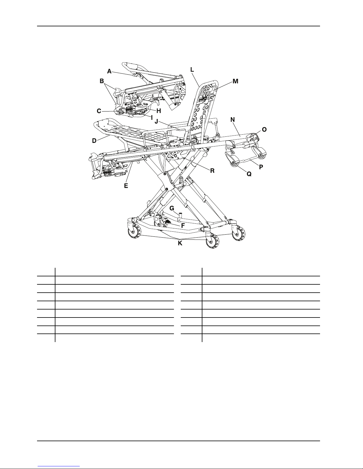
Figure 3: Power-PRO XT
A Footrest release handle J Siderail release handle
B
C
D Footrest M
E
F Wheel lock O Head section release handle
G
H
I
Height adjustment switches
Manual back-up release handle
Height sensor housing (on other side)
Cot retaining post
Battery release
Battery
K
L Backrest
N Retractable head section
P
Q
R
Transport wheels
Backrest adjustment handle
Safety bar
Load wheel
Hydraulic unit
16 6506-209-001 REV F www.stryker.com
Page 23
Product illustration - SMRT
A
C
D
E
F
H
I
G
B
Introduction
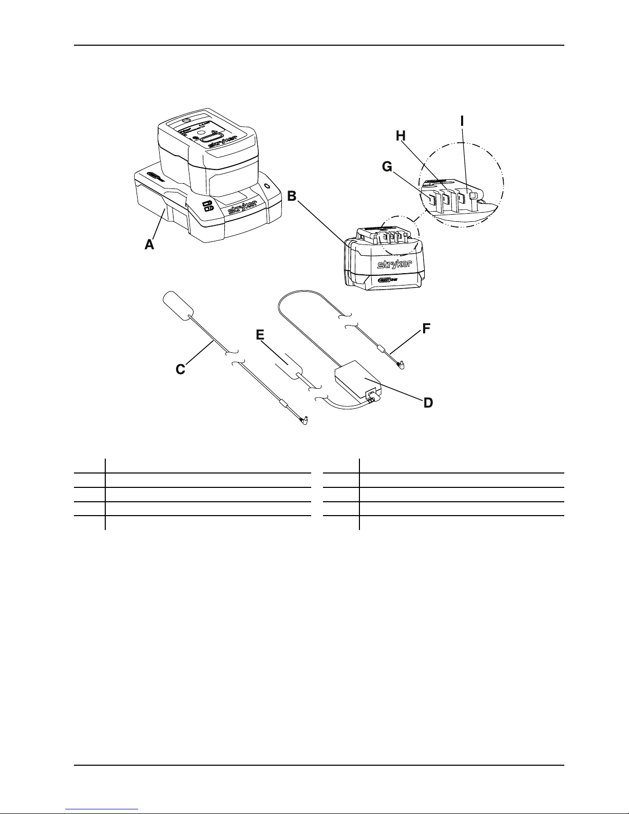
Figure 4: SMRT power system
SMRT charger
A
B SMRT Pak G Data
C DC cable H
AC power supply
D
AC power cord
E
F
I
Output cord
Power (-)
Power (+)
Contact information
Contact Stryker Customer Service or Technical Support at: 1-800-327-0770.
Stryker Medical
3800 E. Centre Avenue
Portage, MI 49002
USA
To view your operations or maintenance manual online, see https://techweb.stryker.com/.
Have the serial number (A) of your Stryker product available when calling Stryker Customer Service or Technical Support.
Include the serial number in all written communication.
www.stryker.com 6506-209-001 REV F 17
Page 24
Introduction
A
Serial number location - Power-PRO
Figure 5: Serial number location
Serial number location - SMRT
The serial number for the SMRT charger is located on the bottom of the unit. The lot number for the SMRT Pak is
located on the top of the SMRT Pak above the red release button.
Date of manufacture
The year of manufacture is the first 2 digits of the serial number for Power-PRO.
18 6506-209-001 REV F www.stryker.com
Page 25

Setup
During setup, unpack the cartons and check all items for proper operation. Make sure that the product operates before
you place it into service.
WARNING
Always install the in-fastener shut-off system in any emergency vehicle that will be used with this cot if using an antler
style cot fastener.
Remove all the shipping and packaging materials from the product before use.
The vehicle patient compartment where the product will be used must have a:
• Smooth rear edge for product loading
• Level floor large enough for the folded product
• Stryker cot fastener system
• Space to install the vehicle safety hook
• In fastener shut-off module installed, if using an antler style cot fastener
Note: Loose items or debris on the vehicle patient compartment floor can interfere with the operation of the vehicle
safety hook and product fastener. Keep the vehicle patient compartment floor clear.
Unpack the SMRT Paks and SMRT charger. Charge the SMRT Pak before use.
When necessary, modify the vehicle to fit the cot. Do not modify the cot.
www.stryker.com 6506-209-001 REV F 19
Page 26

Installation
Installing the cot fastener
The Stryker cot fastener systems are compatible only with cots that conform to the installation specifications.
WARNING
• Install the cot fastener by qualified personnel only. Improper installation could result in injury to the patient or
operator.
• Always make sure that all cots meet the installation specifications for the Stryker cot fastener system.
Note: You may need to adjust the rail clamp assembly to compensate for any variation in the cot retaining post position
depending on the cot manufacturer and model number.
These instructions are intended for cots with antler style cot fastener systems. For crash-rated cot fasteners, see the
appropriate Operations Manual for installation instructions.
Installing the in-fastener shut-off
These instructions are intended for cots with antler style cot fastener systems. For crash-rated cot fasteners, see the
appropriate Operations Manual for installation instructions.
WARNING
• Always position the in-fastener shut-off before you place the cot into service.
• Do not attempt to operate the cot when it is loaded into a cot fastener.
• Always use the in-fastener shut-off to disable the electronic functionality only. Do not use the in-fastener shut-off for
any other purpose.
• Always install the in-fastener shut-off system (if not using a crash-rated cot fastener) in any emergency vehicle that
will be used with this cot.
The cot and antler style cot fastener system have an integrated in-fastener shut-off function that disables the cot motor
when you secure the cot into the cot fastener. Tighten the bolts to secure the fastener before you install the shut-off
bracket. Install the shut-off bracket onto the rail clamp assembly before you place the cot into service.
1. Raise the base and push the cot into the vehicle patient compartment by following the appropriate loading
instructions.
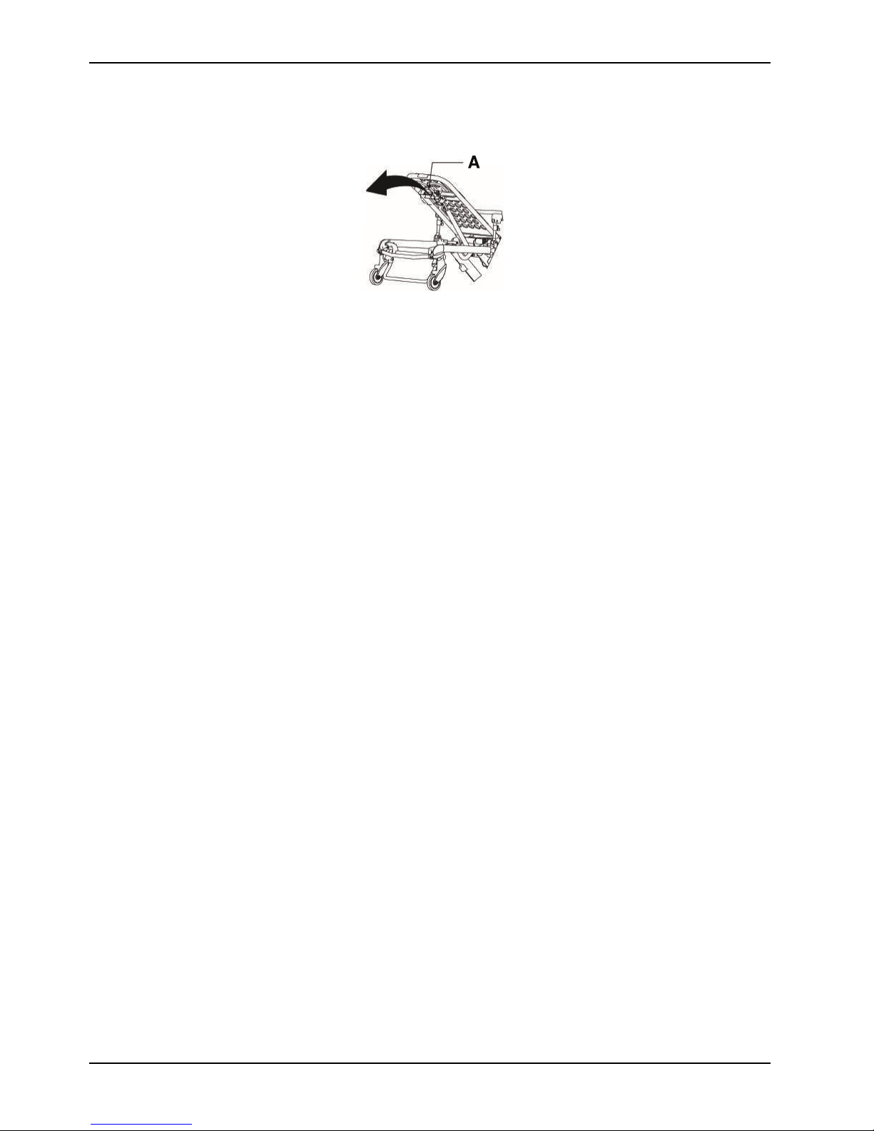
2. Secure the extended head section of the cot into the cot fastener antler.
3. Secure the cot post into the fastener rail clamp.
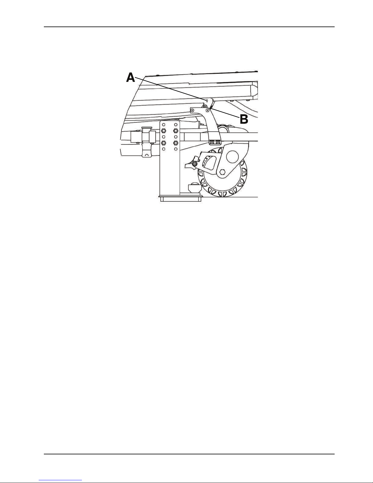
4. Adjust the shut-off bracket along the rail clamp until the diamond (A) on the sensor housing is lined up with the pop
rivet head (B).
Note: Align the diamond (A) on the sensor housing cover with the pop rivet head (B) on the in-ambulance shut-off.
5. Using a T27 Torx driver, securely fasten the bolts to attach the shut-off bracket to the rail clamp assembly.
6. Press the retract (-) button to make sure that the motor does not turn on while the cot is in the fastener. The cot
battery LED indicator will still illuminate. If the motor turns on, readjust the shut-off bracket.
20 6506-209-001 REV F www.stryker.com
Page 27
Installation
A
B
Installing the in-fastener shut-off (Continued)
Figure 6: Adjust shut-off bracket
Selecting the vehicle safety hook
The vehicle safety hook is a device that ships with the cot. The cot safety bar and vehicle safety hook keep the cot from
being accidentally removed from the vehicle and provide increased operator assurance and confidence when loading
and unloading.
Note: These instructions are intended for cots with antler style cot fastener systems. For crash-rated cot fasteners, see
the appropriate Operations Manual for installation instructions. Crash-rated cot fasteners are shipped and installed with
their own vehicle safety hook, thus no additional hook is needed.
The vehicle safety hook was designed for compatibility and proper operation when loading and unloading the cot from a
vehicle that is compliant with Federal Regulation KKK-A-1822. Stryker offers three different types of vehicle safety hooks
that are ordered and shipped with your cot. These vehicle safety hook types meet the needs of various emergency
vehicle configurations, specifically the length and location of the floor structure support that is located in the rear of the
vehicle.
To select which vehicle safety hook is appropriate for your vehicle configuration:
• Consider the location of the floor structure support where there is adequate room to mount the vehicle safety hook.
• Mount the vehicle safety hook into the back of the vehicle. Provide bumper clearance to allow the operators to load
and unload the cot from the vehicle.
• Note the differences in vehicle design. Each vehicle safety hook provides a different mounting location option to
maintain the appropriate distance between the face of the vehicle safety hook and the edge of the door sill.
Due to the differences in vehicle dimensions and the floor structure support locations, each vehicle safety hook allows
for a different mounting location. Select the correct position for your vehicle safety hook installation.
• Positioning of the vehicle safety hook, front to back on page 23
• Positioning of the vehicle safety hook, side to side on page 24
Note: When you replace an existing vehicle safety hook with a new style, adjust the mounting location to maintain the
proper position of the vehicle safety hook face.
www.stryker.com 6506-209-001 REV F 21
Page 28

Installation
6060-036-018
6092-036-018
6060-036-017
Selecting the vehicle safety hook (Continued)
Figure 7: Vehicle safety hook types
Vehicle configuration
CAUTION
• Always set the cot load height to the proper stop height before operation.
• Always have a certified mechanic, familiar with ambulance vehicle construction, install the vehicle safety hook.
Consult the vehicle manufacturer before you install the vehicle safety hook. Make sure that the installation of the
vehicle safety hook does not damage or interfere with the brake lines, oxygen lines, fuel lines, fuel tank, or electrical
wiring of the vehicle.
The cot is compatible with all vehicle deck heights that meet the Federal Specification for the Star-of-Life Ambulance
KKK-A-1822. See specifications for maximum load height.
According to Federal Specification for the Star-of-Life Ambulance KKK-A-1822:
• The rear of the ambulance shall be furnished with a sturdy, full-width, rear bumper, with step secured to the
vehicle’s chassis frame.
• The tread of the step shall have a minimum depth of 5 in. (13 cm) and a maximum depth of 10 in. (25 cm).
• If the step protrudes more than 7 in. (18 cm) from the rear of the vehicle, a fold-up step shall be furnished.
According to federal regulations (reference KKK-A-1822), the bumper height of the vehicle shall be installed equidistant
2 in. (± 5 cm) from the vehicle floor to the ground level, which is defined as the vehicle deck height. Installation of the
vehicle safety hook into any vehicle compliant with this federal specification provides adequate clearance for the cot
base to lower to its fully extended position.
22 6506-209-001 REV F www.stryker.com
Page 29

Installation
DH
2
2
A
B
C D
E
F
A
B
Vehicle configuration (Continued)
Figure 8: Deck and bumper height
A Deck height (DH)
B Bumper height
C Vehicle safety hook
D
E
F Bumper depth
Sill edge
Sill
Positioning of the vehicle safety hook, front to back
Check the front to back and side to side positioning when unloading and loading the cot to make sure that you install the
vehicle safety hook correctly.
To check the front to back positioning:
1. Select the appropriate vehicle safety hook (Selecting the vehicle safety hook on page 21).
2. Position the vehicle safety hook at least 3-3/4 in. from the leading edge of the door sill (A). The recommended
distance from the face of the safety hook to be no less than 3-3/4 in.
3. Make sure that you can secure the vehicle safety hook to the mount in the back of the vehicle.
4. Make sure that you have adequate bumper clearance to allow the cot to be loaded and unloaded from the vehicle.
5. Confirm the side to side placement of the vehicle safety hook (Positioning of the vehicle safety hook, side to side on
page 24).
www.stryker.com 6506-209-001 REV F 23
Page 30

Installation
6060-036-018
6060-036-017
6092-036-018
A
B
Positioning of the vehicle safety hook, front to back (Continued)
Figure 9: Vehicle safety hook placement
A
B Floor structure support
Sill
Positioning of the vehicle safety hook, side to side
Before you install the vehicle safety hook, check the front to back and side to side positioning, when you unload and load
the cot.
To check the side to side positioning:
1. Remove the cot from the cot fastener and unload it from the vehicle.
2. Note the position of the cot load wheels and the cot safety bar when you are remove the cot.
3. Mark the center of the cot safety bar on the vehicle floor.
4. Make sure that the position marked in step 3 is where the cot safety bar connects with the vehicle safety hook every
time when you unload the cot in a variety of positions (such as all the way to the left and all the way to the right).
24 6506-209-001 REV F www.stryker.com
Page 31

Installation
Positioning of the vehicle safety hook, side to side (Continued)
Notes
• If the cot safety bar does not connect with the vehicle safety hook in any of these positions (left, center, or right),
modify the vehicle. Do not modify the cot or the vehicle safety hook.
• If the cot safety bar connects with vehicle safety hook every time, install the vehicle safety hook.
Installing the vehicle safety hook
Before installing the vehicle safety hook, the certified mechanic should plan for the placement of the vehicle safety hook
in the rear of the vehicle patient compartment.
WARNING
• Failure to install the vehicle safety hook may cause injury to the patient or operator.
• Always have a certified mechanic, familiar with ambulance vehicle construction, install the safety hook.
• Always make sure that the cot safety bar connects with the vehicle safety hook before you remove the cot from the
vehicle patient compartment.
Hardware required (not supplied):
• (2) Grade 5, minimum 1/4”-20 socket head cap screws * for the short vehicle safety hook or long vehicle safety hook
• (2) Grade 5, minimum 1/4”-20 flat socket head cap screws * for the J vehicle safety hook
• (2) Flat washers
• (2) Lock washers
• (2) 1/4”-20 nuts
Note: The length of the socket head cap screws depend on the thickness of the vehicle floor. Use screws that are long
enough to go completely through the vehicle patient compartment floor, washer, and nut, with at least two full threads in
the nut.
1. Determine the correct vehicle safety hook front to back and side to side positioning, so the cot safety bar connects
to the vehicle safety hook every time.
• Positioning of the vehicle safety hook, front to back on page 23
• Positioning of the vehicle safety hook, side to side on page 24
2. Drill the holes for the screws.
3. Fasten the vehicle safety hook to the vehicle patient compartment floor.
4. Make sure that the cot safety bar connects with the vehicle safety hook before you remove the cot from the vehicle
patient compartment.
www.stryker.com 6506-209-001 REV F 25
Page 32

Installation
A
B
C
DE
Installing the vehicle safety hook (Continued)
Figure 10: Safety bar secured in the vehicle safety hook
A
B
C Squad bench
D Bumper
E Door frame
After installation, make sure that the cot legs lock into the load position without contacting the vehicle bumper.
26 6506-209-001 REV F www.stryker.com
Figure 11: Vehicle safety hook placement
Top view of vehicle
Vehicle safety hook
Page 33

Operation
Setting cot load height with jog function
The adjustable cot load height with jog function allows you to preset the height of the load wheels to meet the ambulance
deck height up to 36 in. The jog function assists operators when loading on an incline by jogging past the preset load
height. You can set the cot load height from 26 in. to 36 in. (66 cm to 91 cm) as measured from the ground to the bottom
of the load wheel.
To set the cot load height:
1. Locate the sensor housing on the patient right side of the cot.
2. Using a T27 Torx driver, remove the sensor housing cover by loosening the two screws (one on each end).
3. Adjust the left height sensor only inside the sensor housing: (Figure 12 on page 27):
a. Move the sensor toward the head end to increase the set load height or move the sensor toward the foot end to
decrease the set load height.
b. Press the retract (-) button to lower the cot to its lowest position, then press the extend (+) button to raise the
cot to its set load height position.
c. Measure the cot height from the bottom of the load wheels to the floor.
Note: Add an additional 1/2 in. (1,3 cm) to your deck height measurement to allow for variations in patient
weight or with other equipment that may be added to the cot.
d. Repeat steps 3a and 3b until you reach the desired cot load height.
4. Secure the height sensor cables. All cables should lie flat inside the housing between the sensors.
5. Using a T27 Torx driver, reinstall the two screws (removed in step 2) to replace the sensor housing cover.
Checking the battery power level
Use the cot battery LED indictor to check the SMRT Pak power level. A charged SMRT Pak, in working condition,
provides up to 25 calls with a 250 pound patient (actual results may vary). The 24 VDC Power-PRO system and the
SMRT Pak is rated for 2.4 amp-hours of electric energy.
WARNING
Do not remove the battery when the cot is active.
CAUTION
Always charge the battery before you place the product into service. An uncharged or depleted battery may cause poor
product performance.
www.stryker.com 6506-209-001 REV F 27
Figure 12: Adjust left sensor height
Page 34

Operation
B
A
A
6506/6516 6550
Checking the battery power level (Continued)
To check the battery power level, press the retract (-) button on the cot control switch to activate the cot battery LED
indicator. The cot battery LED indicator is located at the foot end control enclosure (shown as a battery symbol).
• The LED is solid green when the battery has a full charge or has an adequate battery power charge.
Note: For best results, use the SMRT Pak until the cot battery LED indicator changes from solid green to flashing
amber.
• The LED flashes amber when you need to charge or replace the battery
Note: The cot battery LED indicator does not have to flash amber before you remove and replace the SMRT Pak,
however, this is considered to be a best practice. You can remove and recharge the SMRT Pak at any time.
• The LED is a solid amber to indicate a battery error.
Notes
• Only use Stryker approved batteries.
• If equipped, the powered cot fastener automatically charges the SMRT Pak battery. Automatic charging occurs
when you lock the cot into the powered cot fastener (no cable or connectors required). The cot battery LED indicator
flashes green for a moment to signify that it is charging.
• Automatic charging will only occur with SMRT Pak batteries.
Checking the hour meter and error display
The hour meter indicates the amount of time (HHH.H hours) that the hydraulics were in use. The error display provides
error code information for troubleshooting.
Use the hour meter (A) (Figure 13 on page 28) to determine the frequency of preventive maintenance. Use the error
display (A) for troubleshooting. The error display overrides the hour meter display when an error occurs.
Figure 13: Checking the hour meter (A), error display (A), and battery status (B)
28 6506-209-001 REV F www.stryker.com
Page 35

Operation
Operating guidelines
WARNING
• Always operate the cot only when all persons are clear of the mechanisms. Entanglement in powered cot
mechanisms can cause serious injury.
• Always inspect SMRT Paks for damage before every use.
• Do not allow untrained assistants to assist in the operation of the product.
• Always follow proper hand placement on hand grips. Keep all hands clear of the red safety bar pivots when you load
or unload the cot or change cot height position.
• Do not ride on the base of the cot.
• Do not transport the cot sideways to avoid the risk of tipping. Always transport the cot in a lowered position, head end
or foot end first to minimize the risk of tipping.
• Always keep hands, fingers, and feet away from moving parts. Use caution when placing your hands and feet near
the base tubes while you raise or lower the cot.
• Always install the in-fastener shut-off system in any emergency vehicle that will be used with this cot if using an
antler style cot fastener.
• Always conduct patient monitoring when the cot is idle. If you hydraulically raise or lower the product you may
temporarily affect electronic patient monitoring equipment.
CAUTION
Always clear any obstacles that may interfere and cause injury to the operator or patient before operating the product.
• Operate the product only as described in this manual.
• Read all labels and instructions on the product before use.
• Practice changing height positions and loading the cot until you fully understand the operation of the product.
• Inspect the SMRT Pak housing and terminal area for any cracks or damage before first and every use.
• Always load or unload an occupied cot with a minimum of two trained operators. Two operators must be present
when a cot is occupied. Stryker recommends that both operators are at the foot end to reduce the load on each
operator. One or two operators can lift from the foot end of the cot.
• Do not adjust, roll, or load the cot into a vehicle without advising the patient. Stay with the patient and control the
product at all times.
• You can transport the cot in any position. Stryker recommends that the operators transport the patient in the lowest
comfortable position to maneuver the cot.
• Only use the wheel locks during patient transfer or without a patient on the product.
• Do not apply a wheel lock when an occupant is on the product or when moving the product to avoid the risk of tipping.
• Use properly trained helpers to control the cot, when necessary.
Proper lifting techniques
When you lift the product and occupant, follow these proper lifting techniques to avoid the risk of injury:
• Keep your hands close to your body
• Keep your back straight
• Coordinate all movement with your partner
• Lift with your legs
• Avoid twisting
www.stryker.com 6506-209-001 REV F 29
Page 36

Operation
Transferring the patient to the cot
WARNING
• Always use all restraint straps to secure the patient on the product. An unrestrained patient may fall from the product
and be injured.
• Do not leave a patient unattended. Hold the product while a patient is on the product.
• Do not apply a wheel lock when a patient is on the product or when you move the product to avoid the risk of tipping.
• Do not use siderails as a patient restraint device.
To transfer the patient to the product:
1. Roll the product to the patient (Rolling the cot with a patient on page 30).
2. Place the product beside the patient and raise or lower the product to the level of the patient.
3. Lower the siderails and open the restraint straps.
4. Transfer the patient to the product. Follow accepted EMS procedures.
5. Secure the patient to the product with all of the restraint straps.
6. Raise the siderails and adjust the backrest and footrest as necessary.
Note: Use the Transfer Flat (6005-001-001) to transfer larger patients.
Rolling the cot with a patient
WARNING
• Always transport the cot at a lower height to reduce the risk of a cot tip. If possible, obtain additional assistance or
take an alternate route.
• Always avoid high obstacles, such as curbing, steps, or rough terrain to avoid the risk of the product tipping over.
To roll the cot with a patient:
1. Position one operator at the foot end and one operator at the head end of the cot.
2. Make sure that the litter is perpendicular when you approach door sills or other low obstacles.
3. Lift each set of wheels over the door sill or obstacle separately.
Raising or lowering the cot
You can raise or lower an unoccupied cot with one operator. If a patient is on the cot, a minimum of two trained operators
(one located at each end of the cot) are required to raise or lower the cot.
WARNING
• Always keep hands, fingers, and feet away from moving parts. Use caution when placing your hands and feet near
the base tubes while you raise or lower the cot.
• Always follow proper hand placement on hand grips. Keep all hands clear of the red safety bar pivots when you load
or unload the cot or change cot height position.
CAUTION
Do not use the jog function to jog past the set cot load height after the cot safety bar connects with the vehicle safety
hook.
30 6506-209-001 REV F www.stryker.com
Page 37

Operation
A
B
C
Raising or lowering the cot (Continued)
To raise or lower the cot:
1. Operator 1 (foot end): Grasp the cot frame and press the:
• Extend (+) button to raise the cot to the desired height
• Retract (-) button to lower the cot to the desired height
2. Operator 2 (head end): Maintain a firm grip on the outer rail until the cot is at the desired height.
Notes
• Operator 2 is required to raise or lower the cot with a patient.
• If you press the extend (+) button on the cot control switch after the cot reaches the set cot load height, the motor
will remain halted until you release the button. After you release the button, press the extend (+) button again to jog
the cot height up higher.
Raising, lowering, or releasing the cot with power
There are two identical cot control switches located on the Power-PRO cots. Press the button on either of these switches
to raise (extend) the cot, lower (retract) the cot, or release the cot from Power-LOAD, if applicable (Figure 14 on page
31).
Reference Name Description
A Release
B Retract (-) Press and hold to lower the litter or
C
www.stryker.com 6506-209-001 REV F 31
Figure 14: Cot control switches
Press to unlock the cot (for use with
Power-LOAD only)
retract the cot undercarriage
Extend (+) Press and hold to raise the litter or
extend the cot undercarriage
Page 38

Operation
Raising or lowering the cot manually with the manual override
In the event of loss of electrical function, you can use the cot manual override. This allows manual operation of the
product until the restoration of the electrical, powered functions. Use the red manual back-up release handle to raise or
lower the cot.
The manual back-up release handle is located is along the patient left side of the lower lift bar at the foot end of the cot.
To raise or lower the cot with the manual back-up release handle:
1. Both operators: Lift the cot during the raise or lower operation to support the weight of the cot at each end.
2. Operator 1 (foot end):
a. Pull the manual back-up release handle toward the lift bar.
b. While pulling the manual back-up release handle, raise or lower the cot to the desired position.
c. Release the handle to lock the cot into position
Notes
• Both operators must lift the cot weight off of the wheels to use the manual extend or retract while a patient is on the
cot.
• Activation of the manual back-up release handle may cause the cot to lower at a slow rate if less than 50 lb (23 kg)
are on the cot.
• Hydraulic fluid will become more viscous when the cot is used for extended periods in cold temperatures. When
using the manual back-up release function to extend the base, while unloading in cold weather conditions, hold the
manual back-up release handle for approximately one second after the cot wheels touch the ground to minimize
sagging of the litter as you remove the cot from the vehicle patient compartment.
Expediting load with the high speed retract mode
When you press the retract (-) button, the cot will enter the high speed retract mode when the cot wheels are not
supporting the weight of the cot and patient.
The high-speed retract mode expedites loading of the cot into a vehicle. The undercarriage retracts toward the highest
position once the weight of the cot and patient is no longer supported by the wheels. Press the retract (-) button to
actuate the control switch.
Loading or unloading a cot with the Power-LOAD option
The cot is fully compatible with the Model 6390 Power-LOAD system if you ordered the cot with the Power-LOAD option
or upgraded your cot with the compatibility kit.
WARNING
• Always use Power-LOAD with the 6085/6086 Performance-PRO XT, 6500/6506 Power-PRO XT, and 6510/6516
Power-PRO IT cots with the Power-LOAD option only. In certain situations, you can use Power-LOAD as a standard
antler for most X-frame cots, but a rail clamp assembly is required for all cots without the Power-LO AD option.
• Always make sure that you use a Power-LOAD date of manufacture cot with the Stryker Model 6390 Power-LOAD
system to avoid the risk of injury.
32 6506-209-001 REV F www.stryker.com
Page 39

Operation
Loading or unloading a cot with the Power-LOAD option (Continued)
Cot Compatibility kit
Model 6506 Power-PRO XT
Model 6516 Power-PRO IT
Model 6086 Performanc e-PRO XT
For more information about using your Power-LOAD compatible cot, see the Power-LOAD Operations Manual.
6506-700-001
6516-700-001
6086-700-001
Loading a cot into a vehicle with an antler style cot fastener
Always load an occupied cot with a minimum of two trained operators. Two operators must be present when a cot is
occupied. Operators must be able to lift the total weight of the patient, cot, and any items on the cot.
WARNING
• Always support the load of the patient, cot, and accessories after the weight is off of the ground.
• Two operators must be present when a cot is occupied.
• Always follow proper hand placement on hand grips. Keep all hands clear of the red safety bar pivots when you load
or unload the cot or change cot height position.
• Do not load the cot into a vehicle with the head section retracted when using a cot fastener. The cot may tip or not
connect with the cot fastener.
Stryker recommends that both operators are at the foot end to reduce the load on each operator. One or two operators
can lift from the foot end of the cot. The higher an operator must lift the cot, the more difficult it may be to hold the weight.
The operator must be able to lift the cot high enough for the cot legs to extend when the cot is unloaded. An operator
may need help if they are too short or if the patient is too heavy to lift when unloading the cot. If you are a shorter
operator, you may need to raise your arms higher to allow the cot legs to extend.
Note: You can load an unoccupied cot into a vehicle with one operator.
To load the cot into a vehicle:
1. Extend and lock the retractable head section.
2. Place the cot in a loading position. A loading position is any position where the load wheels meet the vehicle floor
height.
3. Lift the vehicle bumper, if equipped, to the raised position.
4. Roll the cot to the open door of the vehicle patient compartment.
5. Push the cot forward until the load wheels are on the vehicle patient compartment floor and the cot safety bar
passes the vehicle safety hook.
6. Pull the cot back until the cot safety bar connects to the vehicle safety hook for maximum clearance to lift the base.
7. Make sure that the cot safety bar connects with the vehicle safety hook.
8. Load the cot.
Note: Always use the powered method to load an unoccupied cot with one operator. Do not use the manual method
to load an unoccupied cot with one operator.
• Powered method - using the cot control switches (Raising, lowering, or releasing the cot with power on page 31):
www.stryker.com 6506-209-001 REV F 33
Page 40

Operation
Loading a cot into a vehicle with an antler style cot fastener (Continued)
With both operators at the foot end
(recommended method)
1. Both operators: Grasp the cot
frame at the foot end.
2. Operator 1: Press and hold the
retract (-) button to retract the
cot undercarriage.
• Manual method - using the manual back-up release handle:
1. Operator 1 (at the foot end):
a. Grasp the cot frame at the foot end.
b. Lift the foot end of the cot until you lift the weight off of the cot base.
c. Squeeze and hold the manual back-up release handle.
2. Operator 2 (on the side):
a. Grasp the cot outer rail to stabilize the cot as you retract the cot undercarriage.
b. Raise the cot undercarriage until it stops in the highest position.
With one operator at the foot end
and one operator on the side
1. Operator 1: Grasp the cot
frame at the foot end and
press and hold the retract (-)
button to retract the cot
undercarriage.
2. Operator 2: Grasp the cot
outer rail to stabilize the cot as
the cot undercarriage retracts.
With one operator (when loading
an unoccupied cot)
Grasp the cot frame at the foot
end and press and hold the retract
(-) button to retract the cot
undercarriage.
9. Push the cot into the vehicle patient compartment.
10. Make sure that the cot is secured in the cot fastener (not included).
Note: When you use the manual back-up release handle, do not lift the base rapidly or the movement may appear
sluggish. Lift with a slow, constant motion.
Unloading a cot from a vehicle with an antler style cot fastener
Always unload an occupied cot with a minimum of two trained operators. Two operators must be present when a cot is
occupied. Operators must be able to lift the total weight of the patient, cot, and any items on the cot.
WARNING
• Always support the load of the patient, cot, and accessories after the weight is off of the ground.
• Two operators must be present when a cot is occupied.
• Always follow proper hand placement on hand grips. Keep all hands clear of the red safety bar pivots when you load
or unload the cot or change cot height position.
• Always make sure that the safety bar connects with the vehicle safety hook before you remove the cot from the
vehicle patient compartment to avoid the risk of injury.
• Do not pull or lift on the cot safety bar when you unload the cot.
34 6506-209-001 REV F www.stryker.com
Page 41

Operation
Unloading a cot from a vehicle with an antler style cot fastener (Continued)
CAUTION
• Always set the cot transfer wheels safely on the ground when you unload the cot from the vehicle patient
compartment to avoid the risk of product damage.
• Do not use the jog function to jog past the set cot load height after the cot safety bar connects with the vehicle
safety hook.
Stryker recommends that both operators are at the foot end to reduce the load on each operator. One or two operators
can lift from the foot end of the cot. The higher an operator must lift the cot, the more difficult it may be to hold the weight.
The operator must be able to lift the cot high enough for the cot legs to extend when the cot is unloaded. An operator
may need help if they are too short or if the patient is too heavy to lift when unloading the cot. If you are a shorter
operator, you may need to raise your arms higher to allow the cot legs to extend
Note: You can unload an unoccupied cot from a vehicle with one operator.
To unload the cot from a vehicle:
1. Lift the vehicle bumper, if equipped, to the raised position.
2. Remove the cot from the cot fastener.
3. Unload the cot.
• Manual method - using the manual back-up release handle:
With both operators at the foot end
(recommended method)
1. Both operators: Grasp the cot
frame at the foot end.
2. Operator 1: Pull the manual
back-up release handle to
extend the cot undercarriage.
Pull the cot out of the vehicle
patient compartment until the
safety bar connects with the
vehicle safety hook. Release
the manual back-up release
handle when the base is fully
extended.
3. Operator 2: Make sure that the
safety bar connects with the
vehicle safety hook. Pull the
safety bar release lever
forward to remove the safety
bar from the vehicle safety
hook.
With one operator at the foot end
and one operator on the side
1. Operator 1: Grasp the cot
frame at the foot end. Pull the
manual back-up release
handle to extend the cot
undercarriage. Pull the cot out
of the vehicle patient
compartment until the safety
bar connects with the vehicle
safety hook. Release the
manual back-up release
handle when the base is fully
extended.
2. Operator 2: Make sure that the
safety bar connects with the
vehicle safety hook. Grasp the
cot outer rail to stabilize the
cot. Pull the safety bar release
lever forward to remove the
safety bar from the vehicle
safety hook.
With one operator (when
unloading an unoccupied cot)
1. Grasp the cot frame at the foot
end.
2. Pull the manual back-up
release handle to extend the
cot undercarriage.
3. Pull the cot out of the vehicle
patient compartment until the
safety bar connects with the
vehicle safety hook.
4. Release the manual back-up
release handle when the base
is fully extended.
5. Pull the safety bar release
lever forward to remove the
safety bar from the vehicle
safety hook.
• Powered method - using the cot control switches:
www.stryker.com 6506-209-001 REV F 35
Page 42

Operation
Unloading a cot from a vehicle with an antler style cot fastener (Continued)
With both operators at the foot end With one operator at the foot end
and one operator on the side
1. Both operators: Grasp the cot
frame at the foot end.
2. Both operators: Pull the cot out
of the vehicle patient
compartment until the safety
bar connects with the vehicle
safety hook.
WARNING
Do not press the extend (+)
button until the safety bar
connects with the vehicle
safety hook.
3. Operator 2: Make sure that the
safety bar connects with the
vehicle safety hook.
4. Operator 1: Depress the
extend (+) button to extend the
cot undercarriage.
5. Operator 2: Pull the safety bar
release lever forward to
remove the safety bar from the
vehicle safety hook.
Note: You can use the manual
back-up release handle or a
combination of the manual backup release handle, followed by the
extend (+) button. If you use the
extend (+) button, squeeze and
hold the manual back-up release
handle before you press and hold
the extend (+) button.
1. Operator 1: Grasp the cot
frame at the foot end and pull
the cot out of the vehicle
patient compartment until the
safety bar connects with the
vehicle safety hook.
WARNING
Do not press the extend (+)
button until the safety bar
connects with the vehicle
safety hook.
2. Operator 2: Grasp the cot
outer rail to stabilize the cot.
3. Operator 1: Depress the
extend (+) button to extend the
cot undercarriage.
4. Operator 2: Pull the safety bar
release lever forward to
remove the safety bar from the
vehicle safety hook.
Note: You can use the manual
back-up release handle or a
combination of the manual backup release handle, followed by the
extend (+) button. If you use the
extend (+) button, squeeze and
hold the manual back-up release
handle before you press and hold
the extend (+) button.
With one operator (when
unloading an unoccupied cot)
1. Grasp the cot frame at the foot
end.
2. Pull the cot out of the vehicle
patient compartment until the
safety bar connects with the
vehicle safety hook.
WARNING
Do not press the extend (+)
button until the safety bar
connects with the vehicle
safety hook.
3. Depress the extend (+) button
to extend the cot
undercarriage.
4. Pull the safety bar release
lever forward to remove the
safety bar from the vehicle
safety hook.
4. Remove the load wheels from the vehicle patient compartment floor.
Positioning operators and helpers
WARNING
Always keep your hands clear of the red safety bar pivots when you load, unload, or change the height position of the cot.
36 6506-209-001 REV F www.stryker.com
Page 43

Operation
H
H
O
O
H
H
O
O
O
O
H H
H
H
H HO
O
O
H
H H
H
H
H
H
H OO
Positioning operators and helpers (Continued)
Two operators (O)
Two helpers (H)
Two operators (O)
Four helpers (H)
Changing levels
Rolling Loading and unloading
Raising or lowering the backrest
To raise the backrest, squeeze the backrest adjustment handle to move the backrest to the desired height.
To lower the backrest, squeeze the backrest adjustment handle while you push down on the backrest to the desired
height.
Raising or lowering the siderails
Always lower the siderails when you transfer a patient to the cot or from the cot.
WARNING
Do not use siderails as a patient restraint device.
To raise the siderails, lift up on the siderail until the latch clicks and the siderail locks into place. Always keep the siderails
in the raised position unless you are transferring the patient.
To lower the siderails, squeeze the siderail release handle to release the siderail latch. Guide the siderail down toward
the foot end of the cot until the siderail lays flat. Always lower the siderails when you transfer a patient to or from the cot.
Raising or lowering the siderails (XPS option)
You can order your cot with the expandable patient surface (XPS) option or upgrade your cot to add the XPS option.
WARNING
Do not use siderails as a patient restraint device.
www.stryker.com 6506-209-001 REV F 37
Page 44

Operation
Raising or lowering the siderails (XPS option) (Continued)
CAUTION
• Do not sit or stand on the siderails (XPS option).
• Do not use the siderails (XPS option) as a patient transfer device or surface (for example, to slide a patient from the
cot to another surface).
• Do not position patients with full weight on the siderails (XPS option).
• Do not use the siderails (XPS option) as a push/pull device or to steer the product.
Siderails (XPS option) attach to the cot and are always available for your use. The siderails (XPS option) adjust
according to patient size and lock into seven positions. The siderails also adjust to fit through standard doorways or
elevators.
To raise the siderails, lift up on the siderail until it locks into the desired position.
To lower the siderails, lift up to relieve the weight, then pull the red lever. Always lower the siderails when you transfer a
patient to or from the cot.
The XPS option is not a primary patient support surface. It includes a wider mattress and is intended to enhance patient
comfort.
Extending the retractable head section
Extend the retractable head section before you load the cot into the vehicle patient compartment.
WARNING
• Always lock the head section into place before you operate the cot.
• Do not load the cot into a vehicle with the head section retracted when using a cot fastener. The cot may tip or not
connect with the cot fastener.
To extend the retractable head section:
1. Grasp the outer rail with one hand for support and pull the head section release handle. Rotate the head section
release handle toward the head end of the cot to release the head section from the locked position.
2. While you hold the head section release handle in the released position, pull the head section away from the litter
frame. Lengthen the head section to the extended position.
3. Release the head section release handle to lock the head section in the extended position.
Retracting the retractable head section
Retract the retractable head section to roll the cot in any direction on the load wheels for improved mobility and
maneuverability, even in the lowest position.
WARNING
• Always lock the head section into place before you operate the cot.
• Do not load the cot into a vehicle with the head section retracted when using a cot fastener. The cot may tip or not
connect with the cot fastener.
38 6506-209-001 REV F www.stryker.com
Page 45

Operation
A
B
C
Retracting the retractable head section (Continued)
To retract the retractable head section:
1. Grasp the outer rail with one hand for support and release the head section release handle. Rotate the head section
release handle toward the head end of the cot to release the head section from the locked position.
2. While you hold the head section release handle in the released position, push the head section toward the litter
frame. Retract the head section to the retracted position.
3. Release the head section release handle to lock the head section in the retracted position.
Raising or lowering the footrest
You can adjust the footrest to elevate the patient’s legs.
To raise the footrest, lift the frame as high as possible. The support bracket automatically secures the frame when you
release the footrest.
To lower the footrest, lift the frame and lift up on the footrest release handle until the frame releases the support bracket.
Lower the footrest until it lays flat.
Raising or lowering the optional knee gatch
To raise the optional knee gatch:
1. Lift either of the red lifting loops (A) until the knee gatch is in the highest position (Figure 15 on page 39).
2. Lower the knee gatch to secure the support bracket to the locking mechanism.
3. Make sure that the locking mechanism is secure before you release the lifting loop.
To lower the knee gatch, lift either of the red lifting loops (A) to relieve pressure on the locking mechanism, and while
holding the loop, push on the red footrest release handle (B) until the support bracket is released. Lower the knee gatch
until it lays flat.
To raise the knee gatch in trend, lift the footrest frame (C) as high as possible until the frame locks into place. The
support bracket automatically connects when you release the frame.
To lower the knee gatch in trend, lift the footrest frame (C), and while holding the frame, lift up on the red footrest
release handle (B) until the frame releases the support bracket. Lower the footrest until it lays flat.
www.stryker.com 6506-209-001 REV F 39
Figure 15: Gatch
Page 46

Operation
Applying or releasing a wheel lock
WARNING
• Do not apply a wheel lock when a patient is on the product or when you move the product to avoid the risk of tipping.
• Do not install or apply a wheel lock on a product with worn wheels that are less than 6 in. diameter.
• Do not leave a patient or occupant unattended. Hold the product while a patient or occupant is on the product.
To apply a wheel lock, press down on the pedal until it stops and is resting against the surface of the wheel.
To release a wheel lock, press down on the top of the pedal with your foot or lift up on the pedal with your toe. The top of
the pedal will rest against the caster frame when you release the wheel lock.
Note: Wheel locks help prevent the product from rolling while unattended. Wheel locks may not provide sufficient
resistance on all surfaces or under loads.
Applying or releasing the optional Steer-LOCK
To apply the Steer-LOCK:
1. From the cot foot end, press the red (lock) side of the foot pedal or from the cot head end, press down on either red
pedal.
2. Rotate the cot until at least one head end caster locks.
To release the Steer-LOCK:
• From the cot foot end, press the green (unlock) side of the foot pedal or from the cot head end, lift up on either red
pedal at the head end.
Applying or releasing the optional kickstand for dialysis scale
Use the kickstand to weigh patients on a scale.
WARNING
• Always use two people when using the kickstand.
• Always center the patient weight on the cot before you use the kickstand.
• Always apply the kickstand with your foot only.
• Always lower the cot height before you apply the kickstand for increased stability.
• Do not apply the kickstand during transport. Keep the kickstand in the retracted position.
• Do not use the kickstand as a brake.
• Do not apply the kickstand on a sloped surface.
Note: The optional kickstand (6085-102-000) is not compatible with the optional base storage net (6500-160-000) .
To apply the kickstand:
1. Operator 1: Apply the kickstand with your foot.
2. Operator 2: Lift the foot end of the cot to actuate the kickstand.
3. Both operators: Make sure that the kickstand is in the forward locked position.
40 6506-209-001 REV F www.stryker.com
Page 47

Operation
Applying or releasing the optional kickstand for dialysis scale (Continued)
To release the kickstand, Operator 1 lifts the foot end of the cot until both wheels are off the floor. Operator 2 rolls the
cot forward to make sure that the kickstand retracts.
Securing the patient with the G-rated restraint straps
WARNING
• Always use all restraint straps to secure the patient on the cot. An unrestrained patient may fall from the cot.
• Do not attach restraint straps to the base tubes or cross tubes.
CAUTION
Do not entangle the restraint straps in the base frame when you raise or lower the cot.
Note: Restraint straps are a Type BF applied part.
Secure restraint straps to the cot in the required attachment locations (Figure 16 on page 42). Restraint strap attachment
locations should provide strong anchorage and proper restraint position. Do not allow restraint straps to interfere with
www.stryker.com 6506-209-001 REV F 41
Page 48

Operation
Securing the patient with the G-rated restraint straps (Continued)
equipment or accessories. Buckle the restraint straps across the patient’s shoulders, waist, and legs. Buckle restraint
straps when the cot is not in use.
42 6506-209-001 REV F www.stryker.com
Figure 16: Restraint strap attachment points
Page 49

Operation
Securing the patient with the G-rated restraint straps (Continued)
Installing the shoulder, thigh, or ankle restraints
To install the shoulder, thigh, or ankle restraints:
1. Wrap the restraint strap around the cot frame.
2. Push the restraint strap buckle through the loop.
3. Pull the buckle around the loop to secure the restraint strap to the cot.
Figure 17: Wrap the restraint strap
around the cot frame
Figure 18: Push the restraint strap
buckle through the loop
Figure 19: Secure the restraint
strap to the cot
Installing the waist restraints
To install the waist restraints:
1. Wrap the restraint strap around the cot frame.
2. Push both buckles through the loop for the double buckle strap.
3. Push the buckle and the tongue through the loop for the tongue and buckle strap.
4. Pull the buckle through the loop to secure the restraint strap to the cot.
Note: The waist restraint must form an X with the restraint strap at the shoulder.
Adjusting restraint straps
Open the restraint straps and place them at either side of the cot while you position the patient on the cot mattress.
Lengthen the restraint straps, buckle them around the patient, and shorten them to tighten.
• To open the restraint strap, press the red button on the front of the buckle receiver. This allows you to release the
buckle latch plate and pull it out of the receiver.
• To close the restraint strap, push the latch plate into the receiver until you hear a click.
• To lengthen the restraint strap, grasp the buckle latch plate, turn it at an angle to the webbing, then pull it out. A
hemmed tab at the end of the webbing prevents the latch plate from coming off of the strap.
• To shorten the restraint strap, grasp the hemmed tab and pull the webbing back through the latch plate to tighten.
When you buckle a restraint strap around a patient, secure the latch plate and remove any loose webbing from the cot.
Inspect the restraint straps at least once a month (more if used often). Check for a bent or broken receiver or latch plate,
or torn or frayed webbing. Replace any worn or inoperable restraint strap.
www.stryker.com 6506-209-001 REV F 43
Page 50

Operation
Securing the patient with the G-rated restraint straps (Continued)
Adjusting restraint straps (Continued)
Figure 22: Shorten the restraint
Figure 20: Buckle the straps around
the patient
Figure 21: Lengthen the restraint
strap
strap
Securing a patient with the X-restraint/RUGGED™-X (6500-001-430/6506-001-430)
restraint straps
Secure restraint straps to the cot in the required attachment locations: shoulders waist, thighs, and ankles.
WARNING
• Always use all restraint straps to secure the patient on the cot. An unrestrained patient may fall from the cot.
• Do not attach restraint straps to the base tubes or cross tubes.
CAUTION
Do not entangle the restraint straps in the base frame when you raise or lower the cot.
Note: Restraint straps are a Type BF applied part.
Restraint strap attachment locations should provide strong anchorage and proper restraint position (Figure 23 on page 45
). Do not allow restraint straps to interfere with equipment or accessories. Buckle the restraints across the shoulders,
waist, thighs, and ankles. Buckle all restraint straps when the cot is not in use.
1. Installing the X-restraint/RUGGED-X shoulder restraints on page 45
2. Installing the X-restraint/RUGGED-X waist restraints on page 46
3. Installing the X-restraint/RUGGED-X thigh restraints on page 46
4. Installing the X-restraint/RUGGED-X ankle restraints on page 47
5. Installing the X-restraint/RUGGED-X ankle restraints on page 47
44 6506-209-001 REV F www.stryker.com
Page 51

Operation
1
2
4
3
Securing a patient with the X-restraint/RUGGED™-X (6500-001-430/6506-001-430)
restraint straps (Continued)
Installing the X-restraint/RUGGED-X shoulder restraints
To install the X-restraint/RUGGED-X shoulder restraints:
1. Wrap the restraint around the cot frame.
2. Pull the restraint buckle through the loop, toward the head end of the cot.
3. Feed the buckle under the XPS System.
4. For the Model 6506 Power-PRO XT cot and Model 6086 Performance-PRO XT cot, pull the restraint tight and toward
the back of the backrest.
5. For the Model 6550 Power-PRO TL cot, pull the restraint under the cross tube and toward the back of the backrest.
6. Feed the buckle through the opening in the backrest.
7. Connect the patient right shoulder buckle to the patient left waist buckle.
www.stryker.com 6506-209-001 REV F 45
Figure 23: Restraint strap attachment locations
Page 52

Operation
1 2 3 4 5 6
1 2 3 4 5
1 2 3 4
Securing a patient with the X-restraint/RUGGED™-X (6500-001-430/6506-001-430)
restraint straps (Continued)
Figure 24: Shoulder restraints
Installing the X-restraint/RUGGED-X waist restraints
To install the X-restraint/RUGGED-X waist restraints:
1. Wrap the restraint around the cot frame.
2. Pull the restraint buckles through the loop, toward the head end of the cot.
3. Feed the buckle under the XPS System.
4. Pull the buckles tight. One restraint should angle toward the head end and one should lay straight across the cot.
5. Connect the patient right buckle to the patient left buckle.
Figure 25: Waist restraints
Installing the X-restraint/RUGGED-X thigh restraints
To install the X-restraint/RUGGED-X thigh restraints:
1. Wrap the restraint around the cot litter.
2. Pull the restraint buckle through the loop, toward the head end of the cot.
3. Pull the restraint tight.
4. Connect the patient right buckle to the patient left buckle.
Figure 26: Thigh restraints
46 6506-209-001 REV F www.stryker.com
Page 53

Operation
1 2 3 4
1 2 3 4
Securing a patient with the X-restraint/RUGGED™-X (6500-001-430/6506-001-430)
restraint straps (Continued)
Installing the X-restraint/RUGGED-X ankle restraints
For Model 6506 Power-PRO XT cots and Model 6086 Performance-PRO XT cots built before July 3, 2015 with the gatch
option only.
To install the X-restraint/RUGGED-X ankle restraints:
1. Wrap the restraint around the cot frame. Wrap around both foot end lift bars.
2. Pull the restraint buckle through the loop, toward the head end of the cot.
3. Pull the buckle tight.
4. Connect the patient right buckle to the patient left buckle.
Figure 27: Ankle restraints
Installing the X-restraint/RUGGED-X ankle restraints
For Model 6506 Power-PRO XT cots, Model 6086 Performance -PRO XT cots, and Model 6550 Power-PRO TL cots built
or upgraded after July 3, 2015 with the gatch option or any trend only.
To install the X-restraint/RUGGED-X ankle restraints:
1. Wrap the restraint around the cot litter.
2. Pull the restraint buckle through the loop, toward the head end of the cot.
3. Pull the buckle tight.
4. Connect the patient right buckle to the patient left buckle.
Figure 28: Ankle restraints
Adding a restraint strap extension
Add a restraint strap extension (6082-160-0 50) for extra length when you buckle the lap belt around larger patients.
www.stryker.com 6506-209-001 REV F 47
Page 54

Operation
Adding a restraint strap extension (Continued)
Figure 29: Restraint strap extension
Securing the patient with the Pedi-Mate® infant restraint system
WARNING
Always locate the buckle away from obstructions or accessories on the cot to avoid the risk of accidental release of PediMate® infant restraint system and injury to the infant.
To secure the patient with the Pedi-Mate® infant restraint system:
1. Remove any restraints from the cot.
2. Raise the cot backrest to the full upright position.
3. Position the Pedi-Mate® pad flat on the cot backrest with the black backrest straps facing out.
4. Wrap the straps around the cot backrest and insert the ends of the straps through the brackets.
5. Fasten the buckle.
6. Pull on the end of the adjustable backrest strap to tighten.
7. Insert the mainframe straps between the product frame and the mattress.
8. Insert the buckle behind the litter cross brace and bring it up in front of the litter cross brace.
9. Fasten the buckle around the litter cross brace. Leave slack in the strap for final adjustment.
10. Tighten all straps.
Note: For more information about the Pedi-Mate® infant restraint system, see the manufacturer’s instructions for use,
operation, and care. Safe and proper use of the Pedi-Mate® infant restraint system is at the discretion of the user. Set
methods and procedures to educate and train your staff on the safe operation or maintenance of this product. These are
general instructions only. Keep these instructions for future reference. These instructions are a permanent part of the
product and should remain with the product even if the product is sold.
Pedi-Mate® is a registered trademark of Ferno Washington, Inc.
Installing the child restraint with X-restraint package
To attach the Britax Meridian SICT (series no. 7200/A/2010), Platinum Pro SICT (series no. 7200/A/2013i), and Millenia
SICT (series no. 7200/A/2013/i) Convertible Child Restraint to the cot with the X-restraint package (6500-001-430):
1. Lay the cot flat.
2. Open the waist restraint straps (6500-001-402 and 6500-001-403). Lay the straps to the side and out of the way.
3. Position the child restraint to face the foot end of the cot.
4. Place the child restraint into the reclined position.
5. Raise the cot fowler up to align with the back of the child restraint.
6. Loop the upper anchorage strap with the anchor fitting and attachment clip from the child restraint around the cot
fowler (Figure 30 on page 49). Pull the adjustment strap to tighten and remove slack.
48 6506-209-001 REV F www.stryker.com
Page 55

Operation
Installing the child restraint with X-restraint package (Continued)
7. Pull the waist restraint under the siderail and through the bottom of the child restraint (Figure 31 on page 49).
Figure 30: Anchorage strap location Figure 31: Secure the waist restraint
8. Firmly push down on the seat with your hand while pulling the waist restraint with the other hand to tighten the waist
restraint.
9. Attach one restraint strap (6500-001-4 04) to the foot end lift bars (Figure 32 on page 49) or the outer rail (Figure 33
on page 49).
Figure 32: Attach to the foot end lift bars Figure 33: Attach to the outer rail
10. Pull the restraint strap (6500-001-404) through the foot end of the child restraint (Figure 34 on page 50).
11. Firmly push down on the seat with your hand while pulling the restraint with the other hand to tighten the restraint.
www.stryker.com 6506-209-001 REV F 49
Page 56

Operation
Installing the child restraint with X-restraint package (Continued)
12. While holding the tension, close the rear facing lock-off on the buckle side to hold the tension (Figure 35 on page 50
).
Figure 34: Restraint location Figure 35: Rear facing lock-off
13. Close the rear facing lock-off on the opposite side.
14. Place the baby into the child restraint and secure per manufacturer’s instructions.
Installing the defibrillator platform
CAUTION
• Always secure the defibrillator platform to the product when you use the defibrillator platform.
• Always use and adjust the straps that are provided with the defibrillator platform to secure the defibrillator.
• Always change the installation location or adjust the straps for your specific defibrillator size or shape.
• Do not load the defibrillator platform above the safe working load of 30 lb (13.6 kg).
To install the defibrillator platform:
1. Place the defibrillator platform in the stored position (Figure 36 on page 51).
50 6506-209-001 REV F www.stryker.com
Page 57

Operation
B
C
D
Installing the defibrillator platform (Continued)
2. Open and expand the defibrillator platform legs (Figure 37 on page 50).
Figure 36: Stored position
Figure 37: Open defibrillator platform legs
3. If the product is equipped with an IV pole, raise the IV pole (A) to the up position (Figure 38 on page 51).
4. Place the defibrillator platform on the product frame.
5. Position the inside legs (B) of the defibrillator platform toward the head end of the product (Figure 38 on page 51).
6. Place the latch hook (C) under the litter frame or foot end fastener and push the tab (D) up until it locks into place
on one side with an audible click. Repeat on the other side. For Power-LOAD compatible cots, if equipped, you must
lengthen and attach the straps to the foot end fastener (Figure 40 on page 52).
Figure 38: Raise IV pole and position defibrillator
tray
www.stryker.com 6506-209-001 REV F 51
Figure 39: Latch hook placement
Page 58

Operation
F
Installing the defibrillator platform (Continued)
7. Make sure that the defibrillator platform is secured to the product.
8. Place the defibrillator on the defibrillator platform.
9. Secure the straps (E) to hold the defibrillator on the defibrillator platform (Figure 41 on page 52).
Figure 41: Attach defibrillator platform to the cot
Figure 40: Tab
Note: If the defibrillator platform is not attached to the product after you connect both latch hooks, unlatch the tab. To
adjust, loosen or tighten the strap and then push the tab up until it locks into place with an audible click.
Hanging equipment from the equipment hook
Use the equipment hook to hang additional accessories or equipment, such as defibrillators and monitors.
CAUTION
• Do not load the equipment hook above the safe working load of 35 lb (15.8 kg).
• Always remove all accessories or equipment from the equipment hook when in the vehicle.
52 6506-209-001 REV F www.stryker.com
Page 59

Operation
Hanging equipment from the equipment hook (Continued)
Figure 42: Equipment hook
Installing the head extension with pillow
You can install the head extension assembly on the backrest to provide head end support.
To attach the pillow to the head extension, place the support into the flap on the bottom of the pillow. Secure the pillow to
the Velcro® on the bottom of the support.
Notes
• The head extension with pillow (6100-044-000) is not compatible with the optional equipment hook (6500-147-0 00)
or optional fowler oxygen bottle holder (6500-241-0 00).
• The head extension pillow is a Type BF applied part.
Positioning the two-stage IV pole
CAUTION
Do not load the IV pole above the safe working load of 25 lb (11.3 kg).
Note: The dual two-stage IV poles (6500-312-000 ) are not compatible with either the patient right (6500-310-0 00) or the
patient left (6500-311-000) two-stage IV pole options.
To position the IV pole (Figure 43 on page 54):
1. Lift and pivot the IV pole from the storage position and push down until the IV pole locks into the receptacle (A).
2. To raise the height of the pole, turn the lock actuator (B) counterclockwise and pull up on the telescoping portion (C)
of the pole to raise it to the desired height.
www.stryker.com 6506-209-001 REV F 53
Page 60

Operation
A
B
C
D
Positioning the two-stage IV pole (Continued)
3. Turn the lock actuator (B) clockwise to lock the telescoping portion in place.
4. Hang the IV bags on the IV hook (D).
5. Turn the lock actuator (B) counterclockwise and slide section (C) into the bottom tube.
6. Turn the lock actuator (B) clockwise to tighten.
7. Lift up and pivot the pole down into the storage position (Figure 44 on page 54).
Figure 44: IV pole storage position
Figure 43: IV pole raised position
Positioning the optional three-stage IV pole
CAUTION
Do not load the IV pole above the safe working load of 25 lb (11.3 kg).
Note: The dual three-stage IV poles (6500-317-0 00) are not compatible with either the patient right (6500-315-0 00) or
the patient left (6500-316-000) three-stage IV pole options.
To position the IV pole (Figure 45 on page 55):
1. Lift and pivot the IV pole from the storage position and push down until the IV pole locks into the receptacle (A).
2. To raise the height of the pole, turn the lock actuator (B) counterclockwise and pull up on the telescoping portion (C)
of the pole to raise it to the desired height.
3. Turn the lock actuator (B) clockwise to lock the telescoping portion in place.
4. For a higher IV pole, pull up on section (D) until the spring clip (E) connects.
5. Hang the IV bags on the IV hook (F).
6. To lower the IV pole, push in on the spring clip (E) and slide section (D) down into section (C). Turn the lock actuator
(B) counterclockwise and slide section (C) into the bottom tube.
54 6506-209-001 REV F www.stryker.com
Page 61

Operation
A
B
C
D
E
F
A
B
E
D
C
F
Positioning the optional three-stage IV pole (Continued)
7. Turn the lock actuator (B) clockwise to tighten.
8. Lift up and pivot the pole down into the storage position.
Figure 45: IV pole raised position
Attaching an oxygen bottle to the oxygen bottle holder
CAUTION
• Do not load the oxygen bottle holder above the safe working load of 15 lb (6.8 kg).
• Do not use two oxygen bottle holders at the same time.
To attach an oxygen bottle to the oxygen bottle holder:
1. Place an oxygen bottle in the holder.
2. Insert the lower strap through the buckle and affix the strap onto itself to secure the oxygen bottle to the holder.
www.stryker.com 6506-209-001 REV F 55
Page 62

Operation
A
B
Attaching an oxygen bottle to the oxygen bottle holder (Continued)
Notes
• Do not use the oxygen bottle holder to hold an oxygen bottle holder when the transport vehicle is in motion. Always
place the oxygen bottle holder in an appropriate storage location when the transport vehicle is in motion.
• Inspect the straps and clips for wear between use. Replace the strap if it no longer holds the oxygen bottle.
Attaching an oxygen bottle to the retractable head section oxygen bottle holder
WARNING
Do not pinch your fingers between the fowler bracket and the oxygen bottle if your cot is equipped with the optional
retractable head section oxygen bottle holder.
CAUTION
• Do not load the oxygen bottle holder above the safe working load of 15 lb (6.8 kg).
• Do not use two head end oxygen bottle holders at the same time.
To attach an oxygen bottle to the retractable head section oxygen bottle holder (Figure 46 on page 56):
1. Center the oxygen bottle on the cradled surface of item (A).
2. Tighten both straps (B) around the oxygen bottle.
3. Secure the slack on the straps to the Velcro® on the straps.
Figure 46: Oxygen bottle attachment
Notes
• The optional fowler oxygen bottle holder (6500-241-0 00) is not compatible with the optional retractable head section
oxygen bottle holder (6085-046-000).
• Do not use the oxygen bottle holder to hold an oxygen bottle holder when the transport vehicle is in motion. Always
place the oxygen bottle holder in an appropriate storage location when the transport vehicle is in motion.
56 6506-209-001 REV F www.stryker.com
Page 63

Operation
Attaching an oxygen bottle to the retractable head section oxygen bottle holder
(Continued)
• Inspect the straps and clips for wear between use. Replace the strap if it no longer holds the oxygen bottle.
Installing the optional base storage net
CAUTION
• Do not load the base storage net above the safe working load of 20 lb (9 kg).
• Always be careful when you retract the base to avoid damaging items that are stored in the base storage net.
To install the base storage net, wrap the Velcro® straps around the base tubes.
Installing the backrest storage pouch
CAUTION
• Do not load the backrest storage pouch above the safe working load of 20 lb (9 kg).
• Do not allow the storage pouch to interfere with the operation of the retractable head section.
To install the backrest storage pouch (Figure 47 on page 58):
1. Insert each strap through a hole in the backrest skin.
2. Mount the pouch flat against the backrest.
3. Secure the backrest storage pouch to the cot with the Velcro straps.
www.stryker.com 6506-209-001 REV F 57
Page 64

Operation
Installing the backrest storage pouch (Continued)
Figure 47: Backrest storage pouch
Installing the optional head end storage flat
WARNING
Do not allow the head end storage flat (if equipped) to interfere with the operation of the retractable head section, safety
bar, or vehicle safety hook.
CAUTION
Do not load the head end storage flat above the safe working load of 40 lb (18 kg).
To install the head end storage flat (Figure 48 on page 59):
1. Install the Velcro® straps (A) near the pneumatic cylinder and around the cross tube (C) of the retractable head
section.
2. Buckle the restraint straps (B) around the outer rails of the retractable head section.
58 6506-209-001 REV F www.stryker.com
Page 65

Operation
Installing the optional head end storage flat (Continued)
Figure 48: Head end storage flat
Transferring larger patients
Use the transfer flat (6005-001-001) when you transfer larger patients.
Attaching the mattress
CAUTION
Do not store items under the mattress. Items under the mattress may interfere with product operation.
Two mattress options are available for use with this product. Use the standard gatch bolster (6500-002-150/6506-002-
150) mattress with the standard siderail. Use the wider gatch bolster mattress (6500-003-130/6506-003-130) with the
optional expandable patient surface (XPS).
To attach the mattress to the cot:
1. Align the Velcro® on the back of the mattress with the Velcro® on the cot litter.
2. Attach the strap at the foot end of the mattress through the two holes in the foot end skin on the cot litter.
3. Pull the strap through the buckle and attach the Velcro to secure the strap.
www.stryker.com 6506-209-001 REV F 59
Page 66

Operation
Attaching the mattress (Continued)
Note: The mattress is a Type BF applied part.
Installing a SMRT Pak
The SMRT Pak is designed to be compatible with the Power-PRO XT, Power-PRO IT, and Power-PRO TL cots.
To maximize available battery power, only use SMRT Paks that have been charged within the last 48 hours.
To install the SMRT Pak:
1. Align the tabs in the battery enclosure.
2. Push the SMRT Pak into the enclosure until the latch clicks into place.
The SMRT Pak can remain on the Power-PRO cot between service calls for up to one week or until the cot battery LED
indicator flashes amber.
Removing a SMRT Pak from the cot
After the SMRT Pak has been discharged, remove the SMRT Pak from the Power-PRO cot and replace it with a charged
SMRT Pak.
Running the SMRT Pak repeatedly, without rest periods, can increase the temperature within the cells and reduce life.
For example, lifting a heavy patient up and down several times in rapid succession can reduce the SMRT Pak life.
WARNING
• Do not remove the battery when the cot is activated.
• Do not attempt to open the battery pack for any reason, to avoid the risk of electric shock. If the battery pack case is
cracked or damaged, do not insert it into the charger. Return damaged battery packs to a service center for
recycling.
• Always avoid direct contact with a wet battery or battery enclosures. Contact may cause injury to the patient or
operator.
CAUTION
Always remove the battery if the cot is not going to be used for an extended period of time (more than 24 hours).
To remove the SMRT Pak from the cot:
1. Press the red one hand release button (C) or press the battery release button (A) to release the SMRT Pak (B) from
the cot (Figure 49 on page 61).
2. Slide the released SMRT Pak out of the enclosure.
60 6506-209-001 REV F www.stryker.com
Page 67

Operation
A
B
C
Removing a SMRT Pak from the cot (Continued)
Figure 49: Releasing the battery
Storing the battery
For the longevity, performance, and safety of this equipment, use the original packaging materials when you store or
transport this equipment.
All batteries lose charge during storage or periods of inactivity. A SMRT Pak can lose up to 30 percent of its charge
within 48 hours after you remove it from the SMRT charger. Use and fully charge stored SMRT Paks every three months
to maintain top performance.
Charging the SMRT Pak
The SMRT Pak is intended for use with the SMRT charger only.
WARNING
Do not insert a cracked or damaged SMRT Pak into the SMRT charger. Return damaged SMRT Paks to a service center
for recycling.
Notes
• For extended storage, store the SMRT Pak on the SMRT charger to trickle charge. The SMRT charger keeps the
SMRT Pak charged and ready for use.
• Store the SMRT Pak at room temperature within the allowable temperature charge range of 43 °F to 88 °F (6 °C to
31 °C). Charging the SMRT Pak outside of this recommended temperature range reduces SMRT Pak life and
extends charge time.
To charge the SMRT Pak (Figure 50 on page 62):
1. Insert a clean, dry SMRT Pak into the SMRT charger. Make sure that the SMRT Pak is locked into the SMRT
charger.
www.stryker.com 6506-209-001 REV F 61
Page 68

Operation
A
B
A
B
Charging the SMRT Pak (Continued)
Notes
• The SMRT charger LED indicator (B) will flash green while charging (50 Charging the SMRT Pakon page 62).
The optimum charge time is two hours.
• When the SMRT Pak is charged and ready for use, the SMRT charger LED indicator (B) turns to solid green.
2. Press the red release button (A) (Figure 50 on page 62) and slide the SMRT Pak to release the charged and ready
SMRT Pak from the SMRT charger.
The SMRT charger manages charging regardless of the SMRT Pak charge state.
Figure 50: Charging the SMRT Pak
Checking the SMRT Pak power level with the SMRT charger
Use the SMRT charger LED indicators to check the SMRT Pak power level.
Figure 51: Checking the SMRT Pak power level
• Power connection: Connect or disconnect the SMRT charger from the appropriate power source (Powering the
charger on page 65).
• SMRT charger power LED (A): If the green LED is illuminated, then the SMRT charger has power.
62 6506-209-001 REV F www.stryker.com
Page 69

Operation
Checking the SMRT Pak power level with the SMRT charger (Continued)
• SMRT charger LED indicators (B): Green and amber charger LED indicators provide SMRT Pak status information.
The LEDs may be in a steady or flashing status based on the condition of the SMRT charger or SMRT Pak.
SMRT charger LED indicator Status
Green (flashing) SMRT charger is charging the SMRT Pak. The optimum
charge time is two hours.
Green (solid) SMRT Pak is charged and ready for use
Amber (flashing) SMRT Pak temperature delay. The SMRT charger is
waiting for the SMRT Pak to reach an allowable
temperature range of 43 °F to 88 °F (6 °C to 31 °C).
Amber (solid)
SMRT Pak error. See the troubleshooting section of your
maintenance manual.
Electrical power installation requirements
When configuring the electrical power source for SMRT charger installation, follow these electrical power requirements
for reliable and effective operation.
Power type
AC 100 to 240 VAC
DC 12.5 to 16 VDC
Operational
voltage range
Frequency Maximum
current draw
50/60 Hz 1.20 A 0.05 A N/A
N/A 4.16 A 0.20 A
Standby current
draw
Low voltage
shutoff
10 VDC
Installing the SMRT charger
When installing the SMRT charger, place the SMRT charger in an environmentally controlled location that is:
• Free of excessive dust and moisture
• Kept within a constant temperature range. An allowable temperature range is 43 °F to 88 °F (6 °C to 31 °C). The
optimal temperature range is 65 °F to 75 °F (18 °C to 24 °C).
• Readily accessed for use
Locate and maintain the power supply and power cords to minimize the risk of damage and inadvertent disconnections.
Installing the optional mounting bracket
WARNING
• Always have a certified mechanic, familiar with ambulance vehicle construction, install the optional mounting bracket
and the SMRT charger.
• Always mount the SMRT charger to the optional mounting bracket in an enclosed cabinet and out of patient reach
during transport to comply with established crash test standards.
• Always make sure that the optional mounting bracket is securely attached to the surface.
www.stryker.com 6506-209-001 REV F 63
Page 70

Operation
A
B
Installing the optional mounting bracket (Continued)
To install the optional mounting bracket (Figure 52 on page 64):
1. Use the SMRT charger mounting bracket as a template to mark the location of the mounting holes (A) at the area
where you will install the mounting bracket.
2. Position the mounting bracket, making sure that the:
a. Spring tab (B) is located at the rear of the SMRT charger.
Note: When mounting the bracket to a vertical surface, the spring tab should be horizontal with the spring tab
point to the left (Figure 52 on page 64).
b. Power cord easily plugs into the rear of the SMRT charger.
c. SMRT charger slides from front to back to connect to the bracket after mounting.
d. Bracket is installed correctly for the ambulance or station location:
Ambulance location
• Secure the bracket to a horizontal structural support
surface or shelf using size #10, grade 5 screws
minimum (not supplied).
• Make sure that the selected mounting surface is
strong enough to securely hold the SMRT charger
and SMRT Pak during transport.
• Locate the bracket in an enclosed cabinet and out of
patient reach during transport.
• Allow for easy SMRT Pak installation and removal.
• Locate the power supply within reach of the power
cord.
Station location
• Secure the bracket to a horizontal or vertical
structural support surface using size #10, grade 5
screws minimum (not supplied).
• For vertical installation, position the mounting bracket
so the spring tab is directly below the mounting
screws, so the SMRT Pak remains supported by the
SMRT charger even if the release button is
accidently pressed.
• Allow for easy SMRT Pak installation and removal.
• Locate the power supply within reach of the power
cord.
Installing the charger onto the optional mounting bracket
To install the SMRT charger onto the optional mounting bracket (Figure 53 on page 65):
1. Align the rear keyway slots (A) onto the bracket fasteners (B).
2. Slide the SMRT charger (C) in until it locks into the mounting bracket (D) to secure the charger to the bracket.
64 6506-209-001 REV F www.stryker.com
Figure 52: Mounting bracket
Page 71

Operation
C
D
A
B
Installing the charger onto the optional mounting bracket (Continued)
Figure 53: Installing the charger
Powering the charger
CAUTION
• Always place the electrical SMRT charger power cord where it will not be stepped on, tripped over, or otherwise
subjected to damage or stress.
• Do not touch the SMRT Pak receptacle terminals with metal objects.
To power the SMRT charger (Figure 54 on page 66):
1. Locate the power connection (A) on the back of the SMRT charger.
2. Push the power cord retention tab (B) in to insert the power cord outlet connector into the SMRT charger power
connection.
3. Plug the power adaptor end of the power cord into the power source.
www.stryker.com 6506-209-001 REV F 65
Page 72

Operation
A
B
Powering the charger (Continued)
It is a best practice to use a clean, uninterruptible power source. The SMRT charger continuously illuminates a solid
green power LED when it is connected to a power supply.
Use only Stryker-approved parts to power the SMRT charger.
Figure 54: Powering the charger
Disconnecting the charger
CAUTION
Always grasp and pull the plug, not the cord, when you disconnect the SMRT charger to avoid the risk of damage to the
electrical plug and cord.
To disconnect the SMRT charger, unplug the power cord from the AC or DC power source.
66 6506-209-001 REV F www.stryker.com
Page 73

Accessories
These accessories may be available for use with your product. Confirm availability for your configuration or region. Call
Stryker Customer Service: 1-800-327-0770.
Name Number
Defibrillator platform
Equipment hook 6500-147-000
Head extension with pillow 6100-044-000
IV pole, two-stage, right 6500-310-000
6506-170-000
IV pole, two-stage, left
IV pole, two-stage, dual 6500-312-000
IV pole, three-stage, right 6500-315-000
IV pole, three-stage, left 6500-316-000
IV pole, three-stage, dual 6500-317-000
Mattress, knee gatch bolster 6500-002-150
Mattress, knee gatch bolster, grey 6506-002-150
Mattress, knee gatch bolster, XPS 6500-003-130
Mattress, knee gatch bolster, grey, XPS
Oxygen bottle holder, foot end
Oxygen bottle holder, head end
Oxygen bottle holder, removable
Oxygen bottle holder, retractable head section
Pedi-Mate® restraint package
Power component, AC, charger power supply
Power component, DC, 12 VDC cable, automotive 6500-201-147
6500-311-000
6506-003-130
6500-240-000
6500-241-000
6080-140-000
6085-046-000
6091-300-010
6500-201-148
Power component, DC, 12-24V cable, DIN plug
Storage flat, head end
Storage net, base
Storage pouch, backrest
www.stryker.com 6506-209-001 REV F 67
6500-201-152
6500-128-000
6500-160-000
6500-130-000
Page 74

Cleaning
WARNING
Always use any appropriate personal protective equipment while power washing to avoid inhaling contagion. Power
washing equipment may aerate contamination.
CAUTION
• Do not steam clean or ultrasonically clean the product.
• Do not exceed 180 °F (82 °C) as the maximum water temperature.
• Do not exceed 1500 psi (130.5 bar) as the maximum water pressure. If you are using a hand held wand to wash the
product, keep the pressure nozzle at a minimum of 24 in. (61 cm) from the product.
• Always allow to air dry.
• Always remove the battery before you wash the cot.
• Do not clean, service, or perform maintenance while the product is in use.
The product is power washable. The product may show some signs of oxidation or discoloration from continuous washing.
No degradation of the product’s performance will occur from power washing as long as you follow the proper procedures.
• Follow the cleaning solution manufacturer’s dilution recommendations exactly.
• The preferred method Stryker Medical recommends for power washing the product is with the standard hospital
surgical cart washer or hand held wand unit.
• Clean the cot once a month.
• Clean Velcro® after each use. Saturate Velcro® with disinfectant and allow disinfectant to evaporate. Appropriate
disinfectant for nylon Velcro® should be determined by the service.
• Immersing restraint strap metal buckles can cause buckle corrosion and is not recommended. Rinse with clean water
and allow to air dry to reduce chance of corrosion. Replace restraints if metal buckles are corroded.
Suggested cleaners
In general, when used in concentrations recommended by the manufacturer, either phenolic type or quaternary
(excluding Virex® TB) type disinfectants can be used. Iodophor type disinfectants are not recommended for use because
staining may occur.
WARNING
Always wipe the product with clean water and dry after cleaning. Some cleaning products are corrosive in nature and
may cause damage to the product. Failure to properly rinse and dry the product leaves a corrosive residue on the surface
of the product and may cause premature corrosion of critical components.
Suggested cleaners include:
• Quaternary cleaners (active ingredient - ammonium chloride)
• Phenolic cleaners (active ingredient - o-phenylphenol)
• Chlorinated bleach solution (5.25% - less than 1 part bleach to 100 parts water)
Avoid over saturation. Do not allow the product to stay wet longer than the chemical manufacturer's guidelines for proper
disinfecting.
Note: Failure to follow the above directions when using these types of cleaners may void this product’s warranty.
68 6506-209-001 REV F www.stryker.com
Page 75

Cleaning
Cleaning the charger
WARNING
• Always wear insulated rubber gloves, in addition to personal protective equipment, when cleaning the SMRT Pak to
reduce the risk of injury.
• Always disconnect the SMRT charger from the wall outlet before cleaning to avoid the risk of electrical hazards.
• Do not spray fluid directly onto the SMRT charger.
• Do not power wash the SMRT charger.
• Do not use solvents, lubricants, or other chemicals to clean the SMRT charger unless otherwise directed.
• Do not immerse the SMRT charger in water or allow water to collect on top of the SMRT charger to avoid the risk of
electric shock.
To clean the SMRT charger:
1. Disconnect the SMRT charger from the wall outlet to avoid electrical hazards during cleaning.
2. Wipe surfaces of the SMRT charger with a soft cloth dampened with a non-abrasive, hospital disinfectant.
3. Wipe with a cloth moistened with clean water to remove any cleaning chemicals or residue.
4. Dry thoroughly before placing the SMRT charger back into service.
Cleaning the battery
The SMRT Pak is designed to be power washable. The preferre d method for power washing the SMRT Pak is with the
standard hospital surgical cart washer or hand held wand unit.
WARNING
• Always use any appropriate personal protective equipment while power washing to avoid inhaling contagion. Power
washing equipment may aerate contamination.
• Always wear insulated rubber gloves, in addition to personal protective equipment, when cleaning the SMRT Pak to
reduce the risk of injury.
• Always use only non-conductive materials to wipe the SMRT Pak.
• Always avoid excessive water exposure to the SMRT Pak terminals.
• Always refer to the disinfectant’s Material Safety Data Sheet (MSDS) to verify the pH range. Disinfectants with pH
levels higher than 10.5 may cause the SMRT Pak housing material to crack.
• Do not directly handle or make contact with the SMRT Pak terminals while cleaning to avoid the risk of injury.
• Do not immerse the SMRT Pak in liquid to reduce the risk of electric shock.
• Do not use solvents, lubricants, or other chemicals to clean the SMRT Pak unless otherwise directed.
CAUTION
• Do not steam clean or ultrasonically clean the SMRT Pak.
• Do not exceed 180 °F/82 °C as the maximum water temperature.
• Do not exceed 240 °F/115 °C as the maximum air dry temperature (cart washers).
• Do not exceed 1500 psi (130.5 bar) as the maximum water pressure. If you use a hand held wand to wash the
product, keep the pressure nozzle at a minimum of 24 in. (61 cm) from the product.
www.stryker.com 6506-209-001 REV F 69
Page 76

Cleaning
Cleaning the battery (Continued)
To clean the SMRT Pak:
1. Remove the SMRT Pak from the Power-PRO cot or SMRT charger.
2. Inspect the SMRT Pak housing and terminal area for any cracks or damage.
3. Clean the SMRT Pak with a hospital grade disinfectant with a pH range of 6.5 to 10.5.
4. Rinse the SMRT Pak thoroughly with clean water to remove any cleaning chemical or residue. Position the SMRT
Pak to avoid water from pooling near the terminals.
5. Dry the SMRT Pak thoroughly before insert the SMRT Pak into a Power-PRO cot or SMRT charger.
70 6506-209-001 REV F www.stryker.com
Page 77

Preventive maintenance
WARNING
• Always relieve pressure before you disconnect hydraulic or other lines. Escaping fluid under pressure can penetrate
the skin and cause serious injury. Tighten all connections before you apply pressure. If an accident occurs, see a
doctor immediately.
• Do not use bare hands to check for hydraulic leaks.
CAUTION
• Always use authorized parts to avoid the risk of product damage.
• Always check hoses and lines regularly to avoid damage to the cot. Check and tighten loose connections. Hydraulic
lines, hoses, and connections can fail or loosen due to physical damage, kinks, age, and environment exposure.
• Do not tip the cot onto its load wheels and actuate the product as this will allow air to enter the hydraulic system.
Establish and follow a maintenance schedule and keep records of the maintenance activity. Remove product from
service before you perform the preventive maintenance inspection. You may need to perform preventive maintenance
checks more often based on your level of product usage. Service only by qualified personnel.
When using maintenance products, follow the directions of the manufacturer and reference all material safety data
sheets (MSDS).
Lubrication
The cot has been designed to operate without the need for lubrication.
CAUTION
Do not lubricate the bearings in the X-frame as it will degrade the performance of the cot and may void its warranty.
Regular inspection and adjustments
The following schedule is a general guide to maintenance. Factors such as weather, terrain, geographical location, and
individual usage will alter the required maintenance schedule. If you are unsure how to perform these checks, contact
your Stryker service technician. If you are in doubt as to what intervals to follow to maintain your product, consult your
Stryker service technician. Check each routine and replace worn parts if necessary.
Every month or two hours
Inspect these items every month or two hours, whichever comes first.
Item Inspect
Settings In-fastener shutoff configuration
Cylinder Extend cylinder rod. Wipe the cylinder rod with a soft cloth
and household cleaner.
Cables and wires No hanging wires from routings or connections
Manual backup release handle
Litter Frame and litter
Base Frame and base
Wheels All wheels are secure, roll, and swivel
www.stryker.com 6506-209-001 REV F 71
Manual backup release handle functions
Page 78

Preventive maintenance
Regular inspection and adjustments (Continued)
Item Inspect
Head section
Restraint Restraints function with no excessive wear (such as a
Battery
Charger SMRT charger and parts for cuts in the cord, bent pins or
Safety bar operates. Pull toward the head section to make
sure that the safety bar swings and rotates freely and
pulls back to the home position
bent or broken receiver or latch plate or torn or frayed
webbing)
SMRT Pak housing and terminal area for cracks or
damage before first and every use
contacts, or cracks in the housing before first and every
use
Every three months or six hours
Inspect these items every three months or six hours, whichever comes first.
Item Inspect
Cylinder All fasteners are secure
No hydraulic fluid (red) leaks
Loose fittings - tighten, if needed
Hydraulics
Motor mount fasteners are secure
No hydraulic fluid leaks
No leaks from reservoir
Cables and wires No damage or pinching of wiring harness, cable, or lines
No damaged connectors
Manual backup release handle Base extends and retracts when you pull the manual
backup release handle
Cot does not lower when you pull the manual backup
release handle with 100 lb (45 kg) or more on the cot
Litter All fasteners are secure
Backrest cylinder operates
Adjust pneumatic cylinder for full range of motion, if
required
Base All fasteners are secure
X-frame X-frame expands and retracts
Kickstand (optional)
Retracts fully to the transport position
Bolts are tightened
72 6506-209-001 REV F www.stryker.com
Page 79

Preventive maintenance
Regular inspection and adjustments (Continued)
Item Inspect
Head section
Accessories (optional) All accessories operate (such as IV pole, head extension
All fasteners are secure
Head section extends and locks
and pillow, oxygen bottle holder, and restraint extender)
Every six months or 12 hours
Inspect these items every six months or 12 hours, whichever comes first.
Item Inspect
Hydraulics Hoses and fittings for damage or wear
Hydraulic velocity fuse - place a weight of approximately
50 lb (23 kg) on the cot, raise the cot, lift the cot with two
operators, pull the manual backup release handle, rapidly
set the cot down, and make sure that the cot does not
drop
Electronic controls Extend cot to raised position, measure and check load
height
Jog function operates
High speed retract works
Switches
No damage or wear to either switch
Both switches operate
Litter No bent, broken, or damaged components
No damage or tears on cot grips
Siderails operate and latch
Foot rest operates
Mattress No cracks or tears
Base No bent, broken, or damaged components
Cot retaining post is secure. If not, replace the screw
No excessive damage to X-frame guards
Wheels
Head section No bent, broken, or damaged components
Kickstand (optional) Lubricate the kickstand spring and internal spring housing
Free of debris
Grip bar has no excessive damage or tears
Load wheels are secure and roll
(optional) using Tri-Flow® lubrication.
www.stryker.com 6506-209-001 REV F 73
Page 80

Preventive maintenance
Regular inspection and adjustments (Continued)
Every 12 months or 24 hours
Inspect these items every 12 months or 24 hours, whichever comes first.
Item Inspect
Settings Cot and fastener fit and function
Safety bar connects to the vehicle safety hook
Cylinder Cylinder is adjusted - lock nut is tight and the cot stops
moving when it hits the dead stops
Manual backup release handle Returns to the stowed position
Litter All welds are intact, not cracked, or broken
Warning labels present, legible
Base All welds are intact, not cracked, or broken
Wheels
Retractable head section oxygen bottle holder (optional)
Defibrillator platform (optional) Straps not frayed or torn
Check and adjust wheel locks
Straps and clips for wear
Latch hooks are intact and secure
Foot end fastener part replacement schedule
For Performance-LOAD compatible cots, you must replace the foot end fastener parts every 18,078 calls. This is to
make sure that the Performance -LOAD remains functional. Follow this call volume time table to remain compliant with
this requirement.
Calls per day
≤ 7
8
9 67
10 59
Months
Not applicable
77
74 6506-209-001 REV F www.stryker.com
Page 81

EMC information
CAUTION
• The use of accessories, transducers, and cables, other than those specified or provided by the manufacturer, could
result in increased electromagnetic emissions or decreased electromagnetic immunity and result in improper
operation.
• The emissions characteristics of this equipment make it suitable for use in industrial areas and hospitals (CISPR 11
class A). If it is used in a residential environment, for which CISPR 11 class B is normally required, this equipment
might not offer adequate protection to radio frequency communication services. The user might need to take
mitigation measures, such as relocating or reorienting the equipment.
Guidance and manufacturer’s declaration - electromagnetic emissions
Power-PRO and SMRT charger are intended for use in the electromagnetic environment specified below. The
customer or the user of Power-PRO and SMRT charger should assure that they are used in such an environment.
Emissions test
RF Emissions
CISPR 11
RF Emissions
CISPR 11
RF Emissions
CISPR 11
Harmonic Emissions
IEC 61000-3-2
Compliance
Group 1
Group 2
Power-PRO: Class A
SMRT charger (6500-201-
010): Class B
Power-PRO: N/A
SMRT charger (6500-201-
010): Class A
Electromagnetic environment
Power-PRO and SMRT charger use RF
energy only for its internal function.
Therefore, its RF emissions are very low and
are not likely to cause any interference in
nearby electronic equipment.
Power-PRO with the Power-LOAD
compatibility opton must emit
electromagnetic energy in order to perform
its intended function. Nearby electronic
equipment may be affected.
Power-PRO is suitable for use in all
establishments other than domestic and
those directly connected to the public lowvoltage power supply network that supplies
buildings used for domestic purposes.
The SMRT charger is suitable for use in all
establishments, including domestic
establishments and those directly connected
to the public low-voltage power supply
network that supplies buildings used for
domestic purposes.
The SMRT charger is suitable for use in all
establishments, including domestic
establishments and those directly connected
to the public low-voltage power supply
network that supplies buildings used for
domestic purposes.
Voltage Fluctuations
Flicker Emissions
IEC 61000-3-3
www.stryker.com 6506-209-001 REV F 75
Power-PRO: N/A
SMRT charger (6500-201-
010): complies
The SMRT charger is suitable for use in all
establishments, including domestic
establishments and those directly connected
to the public low-voltage power supply
network that supplies buildings used for
domestic purposes.
Page 82

EMC information
CAUTION
Avoid stacking or placing other equipment adjacent to Power-PRO and SMRT charger to prevent improper operation of
the products. If such use is necessary, carefully observe Power-PRO and SMRT charger and the other equipment to
make sure that they are operating properly.
Recommended separations distances between portable and mobile RF communications equipment and Power-
PRO and SMRT charger
Power-PRO and SMRT charger are intended for use in an electromagnetic environment in which radiated RF
disturbances are controlled. The customer or the user of Power-PRO and SMRT charger can help prevent
electromagnetic interferences by maintaining a minimum distance between portable and mobile RF communications
equipment (transmitters) and Power-PRO and SMRT charger as recommended below, according to the maximum
output power of the communications equipment.
Separation distance according to frequency of transmitter
Rated maximum output
power of transmitter
W
0.01 0.12 0.04 0.07
0.1 0.38 0.11 0.22
1 1.20 0.35 0.70
10 3.79 1.11 2.21
100 12 3.50 7
For transmitters rated at a maximum output power not listed above, the recommended separation distance d in meters
(m) can be estimated using the equation applicable to the frequency of the transmitter, where P is the maximum output
power rating of the transmitter in watts (W) according to the transmitter manufacturer. Note 1: At 80 MHz and 800 MHz,
the separation distance for the higher frequency range applies. Note 2: These guidelines may not apply in all situations.
Electromagnetic propagation is affected by absorption and reflection from structures, objects, and people.
Guidance and manufacturer’s declaration - electromagnetic immunity
Power-PRO and SMRT charger are suitable for use in the electromagnetic environment specified below. The
customer or the user of Power-PRO and SMRT charger should assure that they are used in such an environment.
Immunity test
150 kHz to 80 MHz
D=(1.2) (√P)
IEC 60601 test level
80 MHz to 800 MHz
Compliance level
m
D=(0.35) (√P)
800 MHz to 2.5 GHz
D=(0.70) (√P)
Electromagnetic
environment-guidance
Electrostatic discharge
(ESD)
IEC 61000-4-2
Electrostatic fast
Transient/burst
IEC 61000-4-4
76 6506-209-001 REV F www.stryker.com
+6 kV contact
+8 kV air
+2 kV for power supply
lines
+1 kV for input/output lines
+6 kV contact
+8 kV air
Power-PRO: N/A
SMRT charger (6500-201-
010): +2kV for power
supply lines
+1 kV for input/output lines
Floors should be wood,
concrete or ceramic tile. If
floors are covered with
synthetic material, the
relative humidity should be
at least 30%.
Mains power quality should
be that of a typical
commercial or hospital
environment.
Page 83

(Continued)
EMC information
Guidance and manufacturer’s declaration - electromagnetic immunity
Power-PRO: N/A
Surge
IEC 61000-4-5
Voltage dips, voltage
variations and short
interruptions on power
supply input lines
IEC 61000-4-11
Power frequency (50/60Hz)
magnetic field
IEC 61000-4-8
+1 kV line(s) to line(s)
+2 kV line(s) to earth
SMRT charger (6500-201-
010):
+1 kV line(s) to line(s)
+2 kV line(s) to earth
Power-PRO: N/A
0% U
for 0.5 cycle at 0°,
T
45°, 90°, 135°, 180°, 225°,
270°, and 315°
0% U
for 1 cycle
T
70% U
(30% dip in UT) for
T
25 cycles
0% U
for 250 cycles
T
SMRT charger (6500-201-
010): 0% U
0°, 45°, 90°, 135°, 180°, 225°,
270°, and 315°
0% U
70% U
25 cycles
0% U
3 A/m 3 A/m
for 0.5 cycle at
T
for 1 cycle
T
(30% dip in UT) for
T
for 250 cycles
T
Mains power quality should
be that of a typical
commercial or hospital
environment.
Mains power quality should
be that of a typical
commercial or hospital
environment. If the user of
the SMRT charger requires
continued operation during
power main interruptions, it
is recommended that the
device be powered from an
uninterrupted power supply
or a battery.
Power frequency magnetic
fields should be at levels
characteristic of a typical
location in a typical
commercial or hospital
environment.
Electrical transient
conduction along supply
lines
ISO 7637-2
Note: U
is the a.c. mains voltage before applications of the test level.
T
Conducted RF
IEC 61000-4-6
Radiated RF
IEC 61000-4-3
per ISO 7637-2
3 Vrms
150kHz to 80MHz
10 V/m
80 MHz to 2.5 GHz
Power-PRO: N/A
SMRT Charger (6500-201-
010): per ISO 7637-2
3 V
10 V/m
N/A
Portable and mobile RF
communications equipment
should be used no closer
to any part of Power-PRO
or SMRT charger,
including cables, than the
recommended separation
distance calculated from
the equation appropriate
for the frequency of the
transmitter.
Recommended separation
distance
D=(1.2) (√P)
D=(.35) (√P)
80 MHz to 800 MHz
www.stryker.com 6506-209-001 REV F 77
Page 84

(Continued)
EMC information
Guidance and manufacturer’s declaration - electromagnetic immunity
D=(0.70) (√P)
800 MHz to 2.5 GHz
where P is the maximum
output power rating of the
transmitter in watts (W)
according to the transmitter
manufacturer and d is the
recommended separation
distance in meters (m).
Field strengths from fixed
RF transmitters, as
determined by an
electromagnetic site
should be less than the
compliance level in each
frequency range.
a
b
Interference may occur in
the vicinity of equipment
marked with the following
symbol:
Note 1: At 80 MHz and 800 MHz, the higher frequency range applies.
Note 2: These guidelines may not apply in all situations. Electromagnetic propagation is affected by absorption and
reflection from structures, objects, and people.
a
Field strengths from fixed transmitters, such as base stations for radio (cellular/cordless) telephones and land mobile
radios, amateur radio, AM and FM radio broadcast, and TV broadcast cannot be predicted theoretically with accuracy.
To assess the electromagnetic environment due to fixed RF transmitters, an electromagnetic site survey should be
considered. If the measured field strength in the location in which Power-PRO is used exceeds the applicable RF
compliance level above, the Power-PRO system should be observed to verify normal operation. If abnormal
performance is observed, additional measures may be necessary, such as reorienting or relocating Power-PRO.
b
Over the frequency range 150 kHz to 80 MHz, field strengths are less than 10 V/m.
78 6506-209-001 REV F www.stryker.com
Page 85

Warranty
Stryker EMS, a division of the Stryker Corporation, offers one warranty option in the United States:
Two (2) year parts, labor, and travel. Stryker EMS warrants to the original purchaser that its products should be free from
manufacturing non-conformances that affect product performance and customer satisfaction for a period of two (2)
years after date of delivery. Stryker’s obligation under this warranty is expressly limited to supplying replacement parts
and labor for, or replacing, at its option, any product that is, in the sole discretion of Stryker, found to be defective.
Expendable components, i.e. mattresses, restraints, IV poles, storage nets, storage pouches, oxygen straps, and other
soft goods, have a one (1) year limited warranty.
The Stryker Power-PRO XT is designed for a seven (7) year expected service life under normal use conditions, and with
appropriate periodic maintenance as described in the maintenance manual. Stryker warrants to the original purchaser
that the welds on the Power-PRO XT will be free from structural defects for the expected seven (7) year life of the
product as long as the original purchaser owns the product. Original purchasers will also obtain a three (3) year limited
parts warranty for the X-frame components of the Power-PRO cot and a three (3) year limited power train warranty
covering the motor pump assembly and hydraulic cylinder assembly. Stryker’s obligation under this three (3) year limited
warranty is expressly limited to supplying replacement parts and labor for, or replacing, at its option, any part that is, in
the sole discretion of Stryker, found to be defective.
SMRT Power Warranties. Stryker EMS warrants the SMRT charger for a two (2) year duration. All SMRT Paks are
warranted to be free from manufacturing non-conformances that affect product performance and customer satisfaction
for a period of one (1) year.
Upon Stryker’s request, the purchaser shall return to Stryker’s factory any product or part (freight prepaid by Stryker) for
which an original purchaser makes a warranty claim.
Warranty exclusions and other conditions:
• Any improper use or alteration or repair by unauthorized service providers in such a manner as in Stryker’s judgment
affects the product materially and adversely, shall void this warranty.
• Any repair of Stryker products using parts not provided or authorized by Stryker shall void this warranty.
• There are extenuating circumstances and events that may alter the performance of the products such as an
ambulance accident. In Stryker’s discretion, certain circumstances may allow for evaluation of the product post
ambulance accident which could allow for continued use of the product. If products recommended to be removed
from service are put back into service, Stryker will consider the product as being subject to unusual stress and
improperly maintained. Products which are subject to unusual stress and improper maintenance are not subject to
Stryker’s warranty as noted above. In addition, Stryker will not indemnify any customer for any third-party claims
related to injuries caused by products that have been involved in accidents.
• This warranty is void if the label bearing the serial number of the product has been removed or defaced.
• This warranty is void if the product is not purchased from an authorized Stryker dealer.
This statement constitutes Stryker EMS’s entire warranty with respect to the aforesaid equipment. Stryker makes no
other warranty or representation either expressed or implied, except as set forth herein. There is no warranty on
merchantability and there are no warranties of fitness for any particular purpose. In no event shall Stryker be liable
hereunder for incidental or consequential damages arising from or in any matter related to sales or use of such
equipment.
No employee or representative of Stryker is authorized to change this warranty in any way.
Warranty exclusion and damage limitations
The express warranty set forth herein is the only warranty applicable to the product. Any and all other warranties,
whether express or implied, including any implied warranty of merchantability or fitness for a particular purpose
are expressly excluded by Stryker. In no event shall Stryker be liable for incidental or consequential damages.
www.stryker.com 6506-209-001 REV F 79
Page 86

Warranty
To obtain parts and service
Stryker products are supported by a nationwide network of dedicated Stryker Field Service Representatives. These
representatives are factory trained, available locally, and carry a substantial spare parts inventory to minimize repair time.
Simply call your local representative or call Stryker Customer Service at 1-800-327-0770.
Return authorization
Product cannot be returned without prior approval from the Stryker Customer Service Department. An authorization
number will be provided which must be printed on the returned product. Stryker reserves the right to charge shipping and
restocking fees on returned product. Special, modified, or discontinued products are not subject to return.
Damaged product
ICC Regulations require that claims for damaged product must be made within fifteen (15) days of receipt of the product.
Do not accept damaged shipments unless such damage is noted on the delivery receipt at the time of receipt. Upon
prompt notification, Stryker will file a freight claim with the appropriate carrier for damages incurred. Claims will be limited
in amount to the actual replacement cost. In the event that this information is not received by Stryker within the fifteen (15)
day period following the delivery of the product, or the damage was not noted on the delivery receipt at the time of receipt,
the customer will be responsible for payment of the original invoice in full within thirty (30) days of receipt. Claims for any
incomplete shipments must be made within thirty (30) days of invoice.
International warranty clause
This warranty reflects U.S. domestic policy. Warranty outside the U.S. may vary by country. Contact your local Stryker
Medical representative for additional information.
80 6506-209-001 REV F www.stryker.com
Page 87

Stryker Medical
3800 E. Centre Avenue
Portage, MI 49002
USA
2017/09 6506-209-001 REV F www.stryker.com
 Loading...