

Page 1
IMPORTANT
Keep manual
on file at all
times.
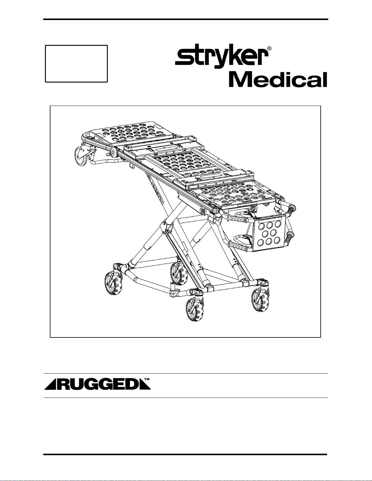
Model 6081 MX–PRO
Incubator Transporter
OPERATIONS/MAINTENANCE MANUAL
For Parts or Technical Assistance
1–800–327–0770
Page 2

Thank you for purchasing the Rugged IT Cot. We strongly believe
Rugged products are the best designed, best manufactured and best
supported products on the market.
If you need any help operating or servicing this product, please contact
Stryker Customer Service at 1-800-327-0770. In addition to facilitating
your parts orders, our customer service and technical support representaĆ
tives can answer your technical and troubleshooting questions.
DISCLAIMER
This manual is not intended to be all inclusive. Safe and proper use of this product is the responsibility of the operator. The general safety warnings and cautions provided in this manual are intended to be guidelines for safe usage. The operator should also remember the federal, state and
local regulations and standards concerning usage. Training on the proper use of this product
should always be provided to new operators before they use this product in the field.
NOTE
Read and understand the incubator manufacturer’s instruction manual prior to installing and using
an incubator on the Rugged IT Cot.
Page 3

Table of Contents
Introduction
Specifications 3. . . . . . . . . . . . . . . . . . . . . . . . . . . . . . . . . . . . . . . . . . . . . . . . . . . . . . . . . . . . . . . . . . . . . . . . . .
Warning / Caution / Note Definition 3. . . . . . . . . . . . . . . . . . . . . . . . . . . . . . . . . . . . . . . . . . . . . . . . . . . . . . . .
Warranty
Obtaining Parts and Service 4. . . . . . . . . . . . . . . . . . . . . . . . . . . . . . . . . . . . . . . . . . . . . . . . . . . . . . . . . . . . . .
Supplemental Warranty Coverage 4. . . . . . . . . . . . . . . . . . . . . . . . . . . . . . . . . . . . . . . . . . . . . . . . . . . . . . . . .
Return Authorization 5. . . . . . . . . . . . . . . . . . . . . . . . . . . . . . . . . . . . . . . . . . . . . . . . . . . . . . . . . . . . . . . . . . . .
Freight Damage Claims 5. . . . . . . . . . . . . . . . . . . . . . . . . . . . . . . . . . . . . . . . . . . . . . . . . . . . . . . . . . . . . . . . . .
Summary of Safety Precautions 6. . . . . . . . . . . . . . . . . . . . . . . . . . . . . . . . . . . . . . . . . . . . . . . . . . . . . . . . . . . . . .
Set–Up Procedures 7. . . . . . . . . . . . . . . . . . . . . . . . . . . . . . . . . . . . . . . . . . . . . . . . . . . . . . . . . . . . . . . . . . . . . . . . .
Component Identification 8. . . . . . . . . . . . . . . . . . . . . . . . . . . . . . . . . . . . . . . . . . . . . . . . . . . . . . . . . . . . . . . . . . . .
Vehicle Safety Hook Installation 9. . . . . . . . . . . . . . . . . . . . . . . . . . . . . . . . . . . . . . . . . . . . . . . . . . . . . . . . . . . . . .
Cot Fastener Installation 10, 11. . . . . . . . . . . . . . . . . . . . . . . . . . . . . . . . . . . . . . . . . . . . . . . . . . . . . . . . . . . . . . . .
Cot Positions 12. . . . . . . . . . . . . . . . . . . . . . . . . . . . . . . . . . . . . . . . . . . . . . . . . . . . . . . . . . . . . . . . . . . . . . . . . . . . .
Rolling the Cot 13. . . . . . . . . . . . . . . . . . . . . . . . . . . . . . . . . . . . . . . . . . . . . . . . . . . . . . . . . . . . . . . . . . . . . . . . . . . .
Loading the Cot into a Vehicle 14. . . . . . . . . . . . . . . . . . . . . . . . . . . . . . . . . . . . . . . . . . . . . . . . . . . . . . . . . . . . . . .
Unloading the Cot from a Vehicle 15. . . . . . . . . . . . . . . . . . . . . . . . . . . . . . . . . . . . . . . . . . . . . . . . . . . . . . . . . . . .
Changing Cot Height 16. . . . . . . . . . . . . . . . . . . . . . . . . . . . . . . . . . . . . . . . . . . . . . . . . . . . . . . . . . . . . . . . . . . . . . .
Operating Break–away Head Section 17. . . . . . . . . . . . . . . . . . . . . . . . . . . . . . . . . . . . . . . . . . . . . . . . . . . . . . . .
Operating I.V. Poles 18, 19. . . . . . . . . . . . . . . . . . . . . . . . . . . . . . . . . . . . . . . . . . . . . . . . . . . . . . . . . . . . . . . . . . . .
Installing the Incubator Adaptor 20. . . . . . . . . . . . . . . . . . . . . . . . . . . . . . . . . . . . . . . . . . . . . . . . . . . . . . . . . . . . .
Installing the Airborne Incubator on the Rugged IT Cot 21. . . . . . . . . . . . . . . . . . . . . . . . . . . . . . . . . . . . . .
Installing the Air–Shields Incubator on the Rugged IT Cot 22, 23. . . . . . . . . . . . . . . . . . . . . . . . . . . . . . . .
Installing the Ohmeda Air–Vac Incubator on the Rugged IT Cot 24. . . . . . . . . . . . . . . . . . . . . . . . . . . . . . .
Installing the Airborne O Bottle Module on the Rugged IT Cot 24.1. . . . . . . . . . . . . . . . . . . . . . . . . . . . .
Preventative Maintenance
Cleaning 25. . . . . . . . . . . . . . . . . . . . . . . . . . . . . . . . . . . . . . . . . . . . . . . . . . . . . . . . . . . . . . . . . . . . . . . . . . . . .
Preventative Maintenance Schedule & Checklist 26. . . . . . . . . . . . . . . . . . . . . . . . . . . . . . . . . . . . . . . . . . .
Maintenance Record 27. . . . . . . . . . . . . . . . . . . . . . . . . . . . . . . . . . . . . . . . . . . . . . . . . . . . . . . . . . . . . . . . . . .
Training Record 28. . . . . . . . . . . . . . . . . . . . . . . . . . . . . . . . . . . . . . . . . . . . . . . . . . . . . . . . . . . . . . . . . . . . . . .
Assembly Drawings and Parts Lists
Cot Assembly 30–32. . . . . . . . . . . . . . . . . . . . . . . . . . . . . . . . . . . . . . . . . . . . . . . . . . . . . . . . . . . . . . . . . . . . . .
Base Assembly 33–35. . . . . . . . . . . . . . . . . . . . . . . . . . . . . . . . . . . . . . . . . . . . . . . . . . . . . . . . . . . . . . . . . . . . .
Wheel Assembly 36. . . . . . . . . . . . . . . . . . . . . . . . . . . . . . . . . . . . . . . . . . . . . . . . . . . . . . . . . . . . . . . . . . . . . . .
Lock Bar Assembly 37. . . . . . . . . . . . . . . . . . . . . . . . . . . . . . . . . . . . . . . . . . . . . . . . . . . . . . . . . . . . . . . . . . . .
Litter Assembly 38, 39. . . . . . . . . . . . . . . . . . . . . . . . . . . . . . . . . . . . . . . . . . . . . . . . . . . . . . . . . . . . . . . . . . . . .
Lift Tube Assembly 40, 41. . . . . . . . . . . . . . . . . . . . . . . . . . . . . . . . . . . . . . . . . . . . . . . . . . . . . . . . . . . . . . . . . .
Breakaway Head Section Assembly 42, 43. . . . . . . . . . . . . . . . . . . . . . . . . . . . . . . . . . . . . . . . . . . . . . . . . . .
Page 4

Table of Contents
Assembly Drawings and Parts Lists (Continued)
Release Handle Assembly 44. . . . . . . . . . . . . . . . . . . . . . . . . . . . . . . . . . . . . . . . . . . . . . . . . . . . . . . . . . . . . .
Airborne Adaptor Mounting Assembly 45. . . . . . . . . . . . . . . . . . . . . . . . . . . . . . . . . . . . . . . . . . . . . . . . . . .
Airborne Incubator Adaptor Assembly 46. . . . . . . . . . . . . . . . . . . . . . . . . . . . . . . . . . . . . . . . . . . . . . . . . . .
Air–Shields Adaptor Mounting Assembly 47. . . . . . . . . . . . . . . . . . . . . . . . . . . . . . . . . . . . . . . . . . . . . . . .
Air–Shields Incubator Adaptor Assembly 48. . . . . . . . . . . . . . . . . . . . . . . . . . . . . . . . . . . . . . . . . . . . . . . .
Ohmeda Air–Vac Adaptor Mounting Assembly 49. . . . . . . . . . . . . . . . . . . . . . . . . . . . . . . . . . . . . . . . . . .
Ohmeda Air–Vac Incubator Adaptor Assembly 50. . . . . . . . . . . . . . . . . . . . . . . . . . . . . . . . . . . . . . . . . . .
Airborne O Bottle Module Mounting Assembly 50.1. . . . . . . . . . . . . . . . . . . . . . . . . . . . . . . . . . . . . . . . .
Airborne O Bottle Module Assembly 50.2. . . . . . . . . . . . . . . . . . . . . . . . . . . . . . . . . . . . . . . . . . . . . . . . .
I.V. Pole Mounting Assembly, Right 51. . . . . . . . . . . . . . . . . . . . . . . . . . . . . . . . . . . . . . . . . . . . . . . . . . . . . . .
2–Stage I.V. Assembly, Right 52. . . . . . . . . . . . . . . . . . . . . . . . . . . . . . . . . . . . . . . . . . . . . . . . . . . . . . . . . . . .
3–Stage I.V. Assembly, Right 53. . . . . . . . . . . . . . . . . . . . . . . . . . . . . . . . . . . . . . . . . . . . . . . . . . . . . . . . . . . .
I.V. Pole Mounting Assembly, Left 54. . . . . . . . . . . . . . . . . . . . . . . . . . . . . . . . . . . . . . . . . . . . . . . . . . . . . . . .
2–Stage I.V. Assembly, Left 55. . . . . . . . . . . . . . . . . . . . . . . . . . . . . . . . . . . . . . . . . . . . . . . . . . . . . . . . . . . . .
3–Stage I.V. Assembly, Left 56. . . . . . . . . . . . . . . . . . . . . . . . . . . . . . . . . . . . . . . . . . . . . . . . . . . . . . . . . . . . .
2–Stage I.V. Pole Assembly 57. . . . . . . . . . . . . . . . . . . . . . . . . . . . . . . . . . . . . . . . . . . . . . . . . . . . . . . . . . . . .
3–Stage I.V. Pole Assembly 58. . . . . . . . . . . . . . . . . . . . . . . . . . . . . . . . . . . . . . . . . . . . . . . . . . . . . . . . . . . . .
3–Stage I.V. Pole 3rd Stage Assembly 59. . . . . . . . . . . . . . . . . . . . . . . . . . . . . . . . . . . . . . . . . . . . . . . . . . . .
Pull Handle Assembly 60. . . . . . . . . . . . . . . . . . . . . . . . . . . . . . . . . . . . . . . . . . . . . . . . . . . . . . . . . . . . . . . . . .
Replacement Parts List 61. . . . . . . . . . . . . . . . . . . . . . . . . . . . . . . . . . . . . . . . . . . . . . . . . . . . . . . . . . . . . . . . . . . .
Page 5

Introduction
INTRODUCTION
This manual is designed to assist you with the operation and maintenance of the Model 6081
MX–PRO Incubator Transporter. Read it thoroughly before using the equipment or beginning any maintenance on it.
SPECIFICATIONS
Overall Length/Minimum Length/Width 80”/62”/23” – 2032 mm./1575 mm./584 mm.
Height – Position 1
Position 2
Position 3
Position 4
Position 5
Position 6
Position 7
Position 8
Weight 72 pounds – 33 kg.
Maximum Weight Capacity 500 pounds – 227 kg.
Caster Diameter/Width 6”/2” – 132 mm./51 mm.
Minimum Operators Required for Loading/Unloading 2
Recommended Fastener Systems Model 6370 Floor Mount Type
Recommended Floor Height Up to 33” – 838 mm.
Roll–In Style Yes
12.0” – 305 mm.
19.5” – 495 mm.
23.5” – 597 mm.
26.5” – 673 mm.
29.5” – 749 mm.
32.0” – 813 mm.
34.5” – 876 mm.
37.0” – 940 mm.
Model 6371 Wall Mount Type
Height measured from bottom of litter surface at seat section to ground level.
Cot is weighed without the incubator mounting kit.
Stryker reserves the right to change specifications without notice.
The MX–PRO IT is designed to conform to the Federal Specification for the Star–of–Life Ambulance KKK–A–1822–D.
WARNING / CAUTION / NOTE DEFINITION
The words WARNING, CAUTION and NOTE carry special meanings and should be carefully reviewed.
WARNING
The personal safety of the patient or user may be involved. Disregarding this information could result in injury
to the patient or user.
CAUTION
These instructions point out special procedures or precautions that must be followed to avoid damaging the
equipment.
NOTE
This provides special information to make maintenance easier or important instructions clearer.
3
Page 6

Warranty
Limited Warranty:
Stryker Medical Division, a division of Stryker Corporation, warrants to the original purchaser that its products
should be free from defects in material and workmanship for a period of one (1) year after date of delivery.
Stryker’s obligation under this warranty is expressly limited to supplying replacement parts and labor for, or
replacing, at its option, any product which is, in the sole discretion of Stryker, found to be defective. Stryker
warrants to the original purchaser that the frame and welds on its beds will be free from structural defects
for as long as the original purchaser owns the bed. If requested by Stryker, products or parts for which a
warranty claim is made shall be returned prepaid to Stryker’s factory. Any improper use or any alteration or
repair by others in such manner as in Stryker’s judgement affects the product materially and adversely shall
void this warranty. No employee or representative of Stryker is authorized to change this warranty in any way.
This statement constitutes Stryker’s entire warranty with respect to the aforesaid equipment. STRYKER
MAKES NO OTHER WARRANTY OR REPRESENTATION, EITHER EXPRESSED OR IMPLIED, EXCEPT
AS SET FORTH HEREIN. THERE IS NO WARRANTY OF MERCHANTABILITY AND THERE ARE NO
WARRANTIES OF FITNESS FOR ANY PARTICULAR PURPOSE. IN NO EVENT SHALL STRYKER BE
LIABLE HEREUNDER FOR INCIDENTAL OR CONSEQUENTIAL DAMAGES ARISING FROM OR IN ANY
MANNER RELATED TO SALES OR USE OF ANY SUCH EQUIPMENT.
To Obtain Parts and Service:
Stryker products are supported by a nationwide network of dedicated Stryker Field Service Representatives.
These representatives are factory trained, available locally, and carry a substantial spare parts inventory to
minimize repair time. Simply call your local representative, or call Stryker Customer Service at (800)
327–0770.
Supplemental Warranty Coverage:
Stryker has developed a comprehensive program of extended warranty options designed to keep your equipment operating at peak performance at the same time it eliminates unexpected costs. We recommend that
these programs be activated before the expiration of the new product warranty to eliminate the potential of
additional equipment upgrade charges. Stryker offers the following Supplemental Warranties:
Extended (Parts and Labor)
All replacement parts (excluding mattresses and consumable items)
Labor and travel for all scheduled and unscheduled calls
Annual Preventive Maintenance Inspections and repairs
JCAHO paperwork for preventive maintenance
Priority Emergency Service
Standard (Labor Only):
Labor and travel for all scheduled and unscheduled calls
Annual Preventive Maintenance Inspections and repairs
JCAHO paperwork for preventive maintenance
Priority Emergency Service
Basic (Parts Only):
All replacement parts (excluding mattresses and consumable items)
Priority Emergency Service
Please call your local representative, or call (800) 327–0770 for further information
4
Page 7

Warranty
Return Authorization:
Merchandise cannot be returned without approval from the Stryker Customer Service Department. An authorization number will be provided which must be printed on the returned merchandise. Stryker reserves the
right to charge shipping and restocking fees on returned items.
SPECIAL, MODIFIED, OR DISCONTINUED ITEMS NOT SUBJECT TO RETURN.
Damaged Merchandise:
ICC Regulations require that claims for damaged merchandise must be made with the carrier within fifteen
(15) days of receipt of merchandise. DO NOT ACCEPT DAMAGED SHIPMENTS UNLESS SUCH DAMAGE
IS NOTED ON THE DELIVERY RECEIPT AT THE TIME OF RECEIPT. Upon prompt notification, Stryker
will file a freight claim with the appropriate carrier for damages incurred. Claim will be limited in amount to
the actual replacement cost. In the event that this information is not received by Stryker within the fifteen
(15) day period following the delivery of the merchandise, or the damage was not noted on the delivery receipt
at the time of receipt, the customer will be responsible for payment of the original invoice in full.
Claims for any short shipment must be made within thirty (30) days of invoice.
International Warranty Clause:
This warranty reflects U.S. domestic policy. Warranty outside the U.S. may vary by country. Please contact
your local Stryker Medical representative for additional information.
Patent Information
Rugged Products are manufactured under the following patents:
United States 5,575,026
5,537,700
Other Patents Pending
5
Page 8

Summary of Safety Precautions
The following is a list of safety precautions that must be observed when operating or servicing this unit. The
precautions are repeated throughout the manual, where applicable. Carefully read this list before using or
servicing the unit.
WARNING
Improper usage of the Cot can cause injury to the patient or operator. Operate the cot
only as described in this manual.
Never leave a patient unattended on the cot or injury could result. Hold the cot securely while a patient
is on the cot.
Adaptors are intended for use only on the Model 6081 Rugged Incubator Transporter Cot. They are
not intended for installation on any other Rugged Cot or any cot from another manufacturer. Using these
adaptors on any cot other than the Rugged Model 6081 may result in damage to the cot and/or injury
to the patient or user.
Verify the adaptor is properly installed on the cot and the incubator is securely fastened to the adaptor prior
to use. An improperly attached adaptor or incubator may cause injury to the patient or user.
Be sure the undercarriage has engaged and locked before removing the loading wheels from the patient
compartment floor of the vehicle. An unlocked undercarriage will not support the cot and injury to the patient and/or operator could result.
Do not allow untrained helpers to assist in the operation of the cot. Untrained technicians/helpers can
cause injury to the patient or themselves.
Grasping the Cot improperly can cause injury. Grasp only the lifting bars to lift the cot.
Keep hands, fingers and feet away from moving parts. To avoid injury , use extreme caution when placing
your feet on the base tubes while raising and lowering the cot.
Do not modify the Cot. Modifying the cot can cause unpredictable operation resulting
in injury to the patient or operator. Modifying the cot will also void its warranty (see page 4).
Have the vehicle safety hook installed by a certified mechanic. Improper safety hook installation can
cause injury to the patient or operator or damage to the unit.
Failure to use the vehicle safety hook can cause injury to the patient or operator. Install and use the safety
hook as described in this manual.
Do not pull on the safety bar when unloading the cot. Damage to the safety bar could result and injury
to the patient or operator could occur.
Improper maintenance can cause injury or damage to the unit. Maintain the cot as described in this manu-
al. Use only Stryker approved parts and maintenance procedures. Using unapproved parts and procedures could cause unpredictable operation and/or injury and will void the product warranty.
Do not step or ride on the base of the cot. Damage to the cot could occur, resulting in
injury to the patient or operator.
Failure to properly clean or dispose of contaminated cot components will increase the risk of exposure
to bloodborne pathogens and may cause injury to the patient or the operator.
Do not exceed the 500 pound (227 kg.) weight limit of the cot, including incubator, equipment and patient.
Damage to the cot and/or injury to the patient or user could occur.
An unrestrained patient can be injured during transport. Always follow the incubator manufacturer’s in-
structions for restraining the patient during transport.
CAUTION
Damage to the cot can occur if the cot is lowered in the shortened position. Use only positions 5–8 (see
page 12) when the cot is shortened.
Lifting the cot by the safety bar can cause damage to the cot unless the cot is equipped with the lift capable
safety bar. Lift the cot only by the lifting bars.
Do not allow the cot undercarriage to drop unassisted (commonly known as a “hot drop”) when removing
the cot from the vehicle. Repeated hot dropping will cause premature wear or damage to the cot.
6
Page 9

Set–Up Procedures
Unpack the cartons and check all items for proper operation. It is important that the Cot is
working properly before it is put into service. Have a qualified service person use the following list and the
operation instructions to check the cot before it is put into service.
All fasteners secure (reference all assembly prints)
All welds intact, not cracked or broken
No bent or broken tubing or sheet metal
No debris in wheels
All wheels secure, rolling and swivelling properly
Optional accessories intact and operating properly
Height positioning latch functioning properly
Cot secure in each height position
Undercarriage folds properly
Break–away head section operating properly
Safety bar operating properly
Does the vehicle safety hook engage the safety bar so that the cot loads and unloads easily from the ve-
hicle?
Is there an approved crash–stable fastener (Stryker part number 6370 or 6371 – not included) installed
in the vehicle?
The patient compartment of the vehicle in which the Cot will be used must have:
A smooth rear edge for cot loading.
A level floor large enough for the folded cot.
Stryker 6370 or 6371 crash stable cot fastener (not included).
33” (840 mm.) maximum loading height.
Space to install the safety hook.
When necessary, modify the vehicle to fit the cot. Do not modify the cot.
WARNING
Do not modify the Cot. Modifying the cot can cause unpredictable operation resulting in injury to the patient or operator. Modifying the cot will also void its warranty (see page 4).
7
Page 10
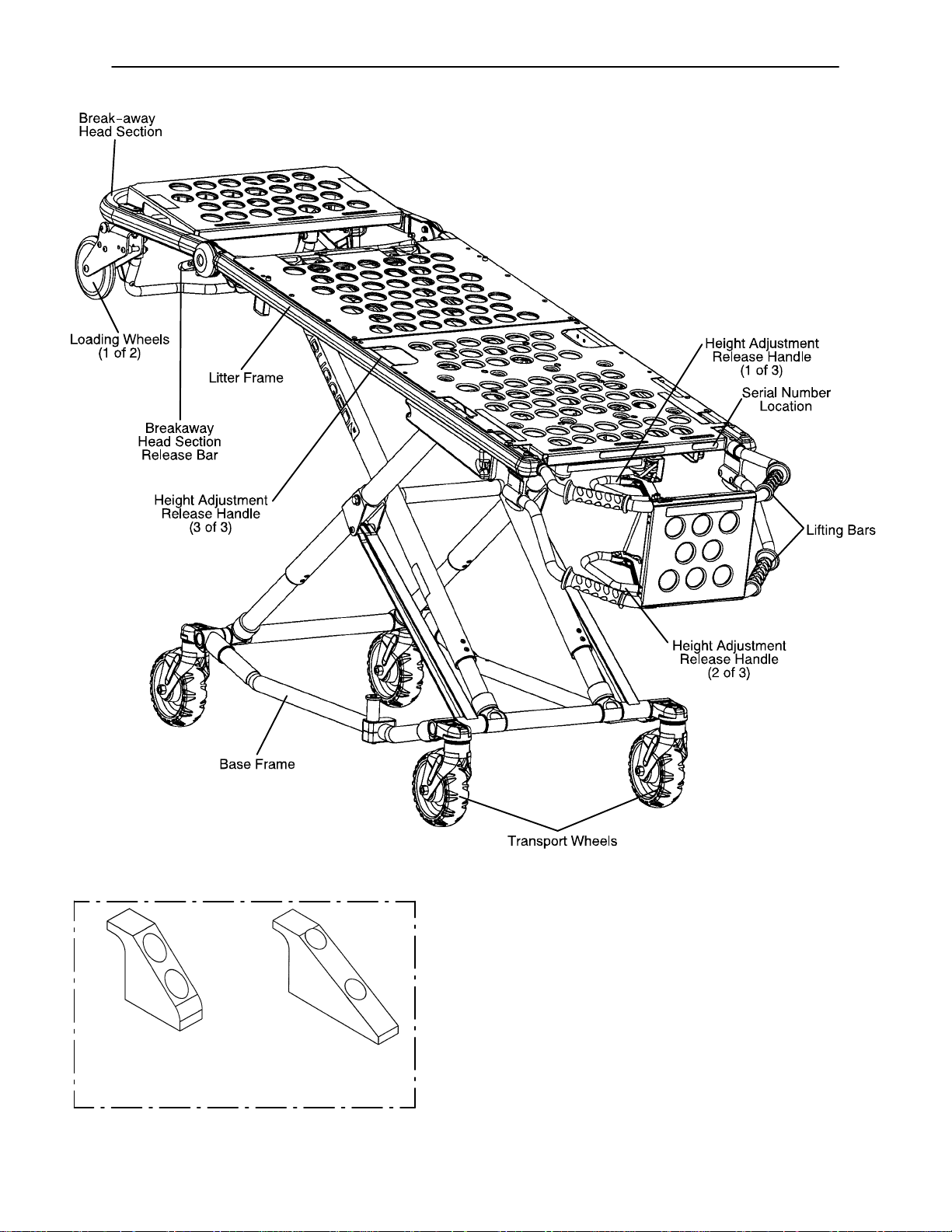
Component Identification
SHORT SAFETY HOOK
(For installation instructions, see page 9)
LONG SAFETY HOOK
8
Page 11
Vehicle Safety Hook Installation
The vehicle safety hook is a device shipped with the
cot. The safety hook activates the safety bar and prevents the cot from being removed from the vehicle accidently.
Installation of the safety hook should be done by a certified mechanic familiar with ambulance construction.
Consult the vehicle manufacturer before installing the
safety hook and be sure the installation of the safety
hook does not damage or intefere with the brake lines,
oxygen lines, fuel lines, fuel tank or the electrical wiring
of the vehicle.
Required Hardware for Installation of the Safety
Hook (Not Supplied)
(2) Grade 5, 1/4”–20 Socket Head Cap Screws*
(2) Flat Washers
(2) Lock Washers
(2) 1/4”–20 Nuts
* The length of the socket head cap screws depends
on the thickness of the vehicle floor. Use screws long
enough to go completely through the patient
compartment floor, washer and nut by at least two full
threads.
Place the cot in the cot fastener. Remove the cot from
the fastener and unload it from the vehicle. While the
cot is being removed from the vehicle, note the position
of the unloading wheels and the safety bar.
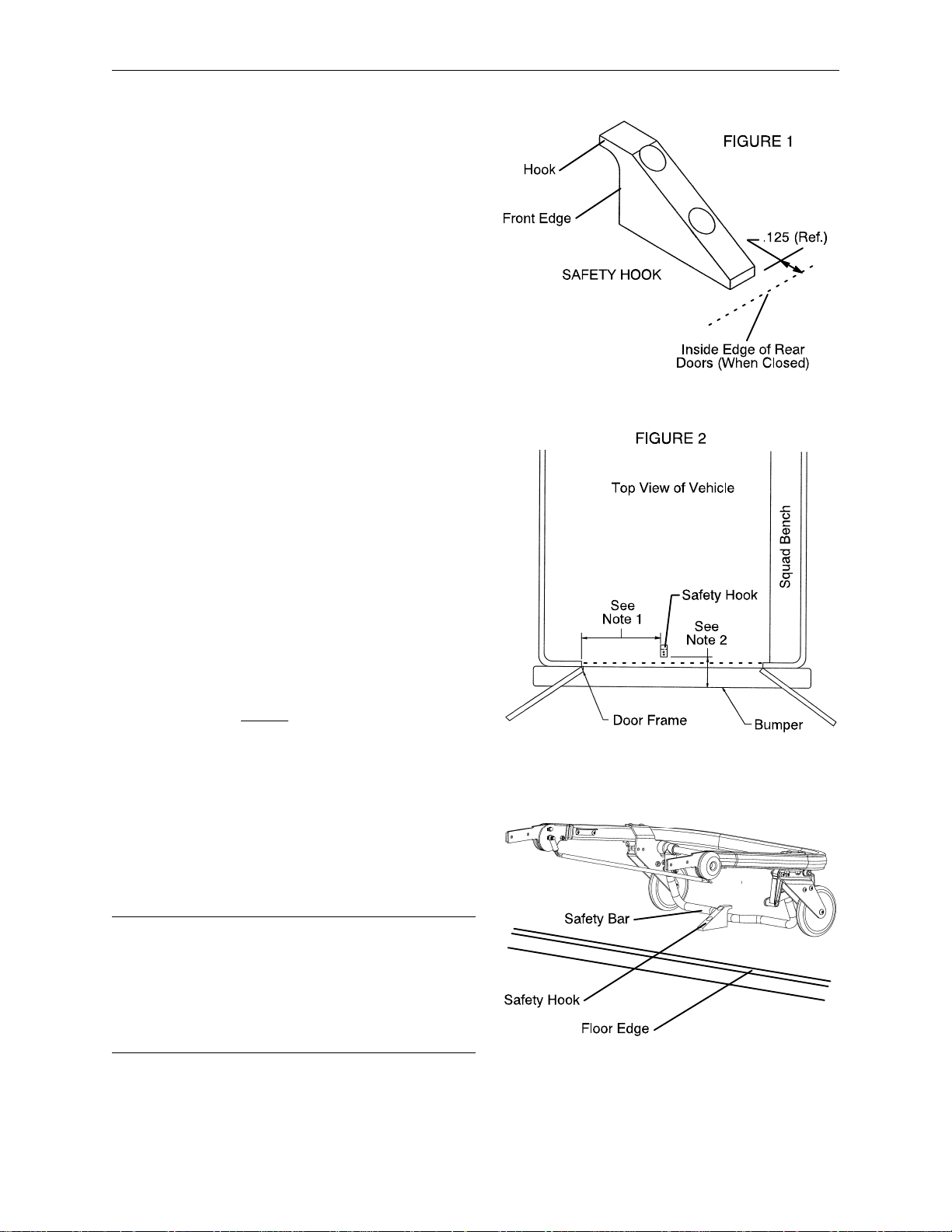
NOTE 1. Center the safety hook on the cot safety bar
with the hook facing the front of the vehicle. Be sure
the safety hook will always engage the safety bar when
the cot is unloaded from the vehicle.
NOTE 2. The safety hook should be installed as close
to the rear of the vehicle as possible while allowing the
vehicle doors to close (see Figures 1 & 2). Be sure the
bumper and the bumper step do not interfere with the
folding and unfolding of the cot’s undercarriage.
Mark the desired position of the safety hook on the patient compartment floor. Drill the holes for the socket
head cap screws. Attach the safety hook to the patient
compartment floor.
WARNING
Improper safety hook installation can cause injury to
the patient and/or operator or damage to the cot. Have
a certified mechanic install the safety hook.
Failure to install the safety hook can cause injury to the
patient or operator. Install and use the safety hook as
described in this manual.
9
Page 12

Cot Fastener Installation
The Stryker Model 6370 and 6371 Cot Fastener systems are designed to be compatible only with cots which
conform to the installation specifications listed on page 11. Ambulance cots which currently meet these specifications are:
Stryker
Model 6060 DX Emergency Transport
Model 6070 LX Emergency Transport
Model 6080 MX–PRO
Model 6081 MX–PRO Incubator Transporter
Model 6090 EZ–PRO
Model 6091 EZ–PRO2
Ferno–Washington
Model 29–M Three Level Roll–In Cot*
Model 93 ES Squadmate*
Model 93 EX Squadmate*
Model 35–A Mobile Transporter*
Model 35–A+ Mobile Transporter Plus*
Model 35–IT Incubator Transporter*
WARNING
It is the responsibility of the cot operator to ensure that the cot being used in the Stryker Model 6370 or 6371
Cot Fastener Systems meets the installation specifications listed on page 11. Injury may result if a non–com-
patible cot is used in the Stryker Model 6370 or 6371 Fastener System.
NOTE
Adjustment of the rail clamp assembly may be required in order to compensate for any variation in cot retaining post position depending on the ambulance cot manufacturer and model number.
For more detailed installation and operation instructions for the Stryker Model 6370 and 6371 Cot Fastener
systems, refer to part number 6370–90–10 Rugged Cot Fastener Installation/Operation Instructions.
* 1999 model year or earlier. Stryker is not responsible for changes in specifications to other manufacturer’s
cots.
10
Page 13
Cot Fastener Installation
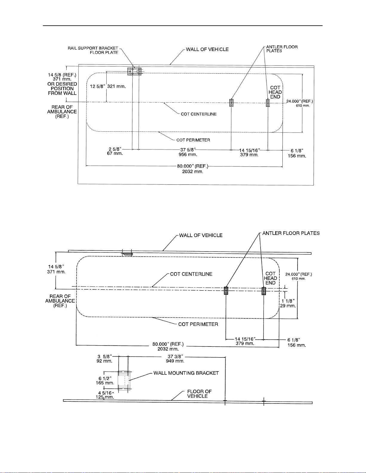
INSTALLATION SPECIFICATIONS – FLOOR MOUNT FASTENER (MODEL 6370)
INSTALLATION SPECIFICATIONS – WALL MOUNT FASTENER (MODEL 6371)
11
Page 14
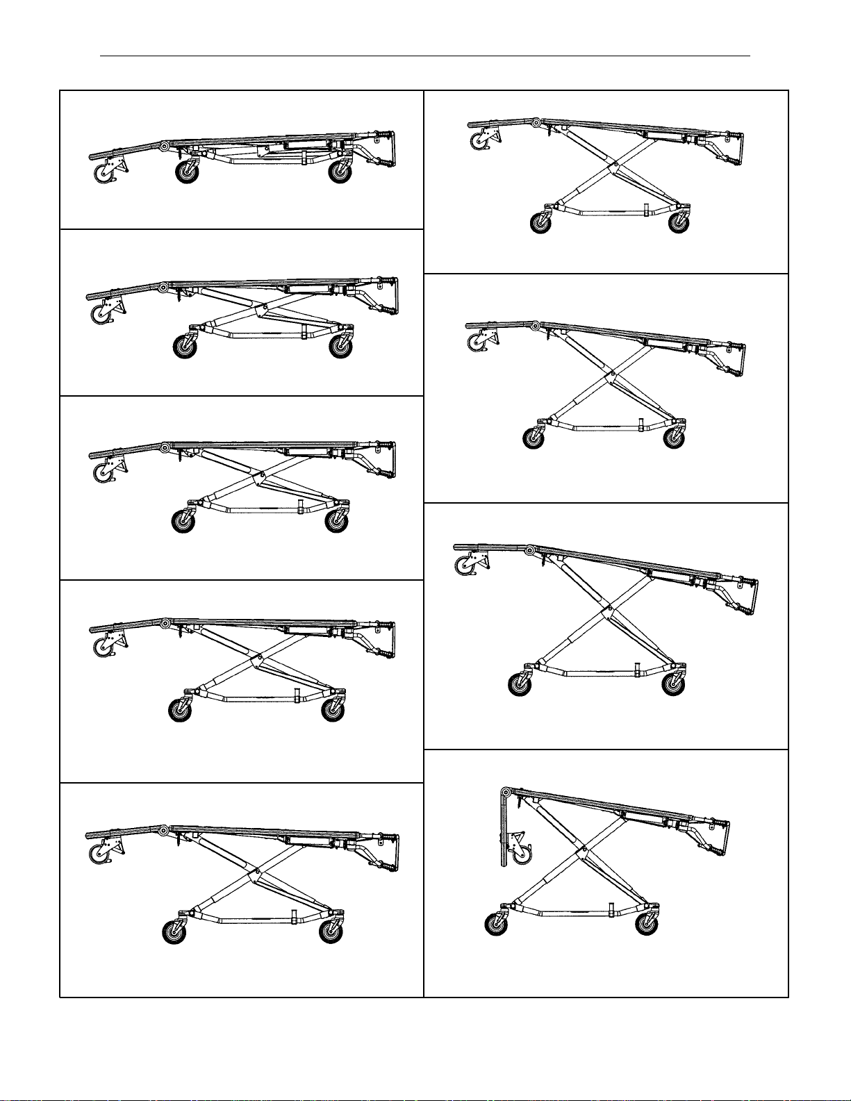
Cot Positions
Position 1 – Use for incubator transfer/storage.
Position 2 – Use for incubator transfer/cot rolling.
Position 6 – Use for incubator transfer/cot rolling.
Position 3 – Use for incubator transfer/cot rolling.
Position 4 – Use for incubator transfer/cot rolling.
Position 7 – Use for vehicle loading only.
Position 8 – Use for vehicle loading only.
Position 5 – Use for incubator transfer/cot rolling.
Use for cot rolling in positions 5 & 6 when space is limited.
12
Page 15

Cot Operation
Operating Guidelines
Use the Cot only as described in this manual.
Read all labels and instructions on the cot before using the cot.
Two operators are required to manipulate the cot. Use additional properly trained attendants when work-
ing with heavy equipment. The operators should maintain control of the cot and the release handles and
instruct the additional attendants appropriately.
Do not adjust, roll or load the cot without advising all the attendants. Stay with the patient and control the
cot at all times.
Rolling the Cot
Verify the incubator is secured in the adaptor. Place the cot in positions 2–6 for rolling (see page 12 for cot
positions). When rolling the cot, position an operator at the foot end and one at the head end at all times.
NOTE
Placing the cot in position 3 or position 4 for rolling is recommended with an incubator on the cot. In these
positions, the incubator will be in a level position for transporting.
WARNING
Rolling the cot in a loading position (7 & 8) could cause the cot to tip resulting in injury to the patient or operator.
Use only the recommended positions (2–6) when rolling the cot.
To prevent injury, operators must assist any additional attendants with the placement of their hands to avoid
possible pinch points on the cot.
13
Page 16
Cot Operation
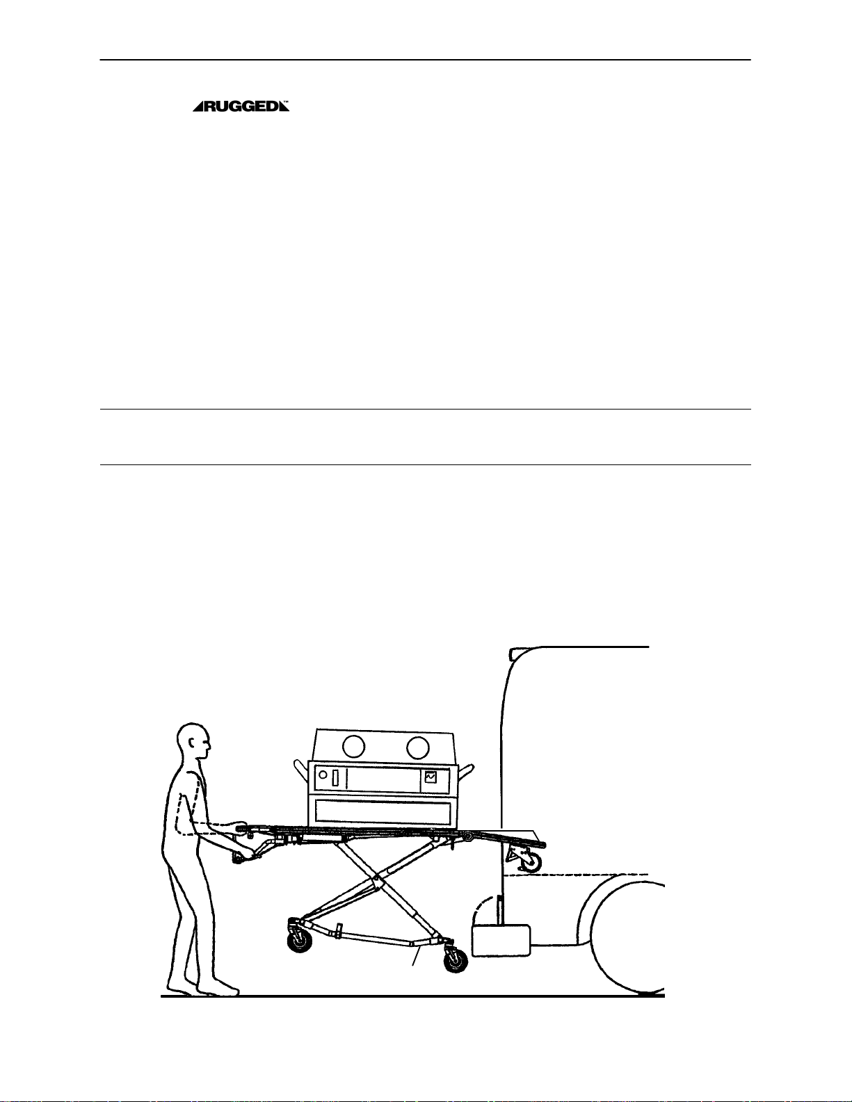
Loading the Cot into a Vehicle
When loading the cot into a vehicle, an operator should remember the following important issues:
There must be a safety hook properly installed in the vehicle so that the bumper does not interfere with
the front legs of the base frame. (See page 9 for safety hook installation instructions.)
The operator(s) must be able to lift the total weight of the patient, cot, incubator and any other items on
the cot.
The higher the operator must lift the cot, the more difficult it becomes to hold the weight. The operator
may need help loading the cot into a vehicle if he/she is too short or if the cot is too heavy for the operator
to lift safely.
The operator must be able to lift the cot high enough for the cot’s legs to unfold completely and lock when
the cot is unloaded. A shorter operator will have to raise his/her arms higher to enable the undercarriage
to unfold.
Place the cot in a loading position (position 7 or 8 – see page 12). Roll the cot to the open door of the patient
compartment. Fold the vehicle bumper to the raised position (if available).
Push the cot forward until the loading wheels are on the patient compartment floor and the safety bar passes
the safety hook.
WARNING
Failure to use the safety hook can cause injury to the patient or operator. Install and use the safety hook as
described in this manual.
Operator 1 – Grasp the cot frame at the foot end. Lift the foot end of the cot until the weight is off the latching
mechanism. Squeeze and hold the release handle (location A or B).
Operator 2 – Grasp the base frame where indicated (location C). Raise and hold the undercarriage until it
stops in its uppermost position.
Both operators – Push the cot into the patient compartment, engaging the cot fastener (not included).
NOTE
Loose items or debris on the patient compartment floor can interfere with the operation of the safety hook
and cot fastener. Keep the patient compartment floor clear.
A
B
C
14
Page 17

Cot Operation
Unloading the Cot from a Vehicle
Properly disconnect the incubator from any vehicle mounted equipment or instrumentation before unloading
the cot from the vehicle.
Disengage the cot from the cot fastener . (For more detailed instructions, reference the cot fastener installation/operation instruction manual – Stryker part number 6370–90–10.)
Operator 1 – Grasp the cot frame. Pull the cot from the patient compartment until the safety bar engages
the safety hook.
WARNING
Failure to use the safety hook can cause injury to the patient or operator. Install and use the safety hook as
described in this manual.
Operator 2 – Grasp the base frame where indicated, lift slightly, and lower the base frame to its fully extended
position while operator 1 squeezes and holds the release handle.
Operator 1 – Let go of the release handle and be sure the undercarriage locks into place.
Operator 2 – Disengage the safety bar from the safety hook by pushing the safety release lever forward.
WARNING
Do not pull or lift on the safety bar when unloading the cot. Damage to the safety bar could result and injury
to the patient or operator could occur.
Remove the cot from the vehicle. Place the cot in a rolling position (positions 2–6 – see page 12).
CAUTION
Do not allow the cot undercarriage to drop unassisted (commonly known as a “hot drop”) when removing the
cot from the vehicle. Repeated hot dropping will cause premature wear or damage to the cot.
WARNING
Be sure the undercarriage has engaged before removing the loading wheels from the patient compartment
floor of the vehicle. An unlocked undercarriage will not support the cot and injury to the patient or operator
could result.
15
Page 18
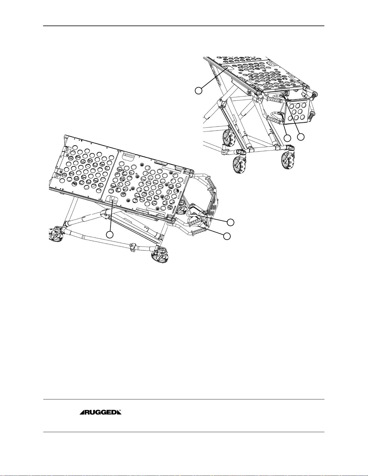
Changing Cot Height
Cot Operation
C
B
A
FOOT END
B
C
A
NOTE
Changing the cot height requires a minimum of two operators, positioned at both ends or on each side of the
cot. Each operator must grasp the cot frame securely.
To lower the cot from the ends, the operator at the foot end of the cot positions his/her hands so the release
handle (A or B) can be squeezed while a secure grip is maintained on the lifting bars. Both operators must
lift the cot until the weight is off the latching mechanism (approximately 1/4” – 6 mm.). The operator at the
foot end squeezes and holds the release handle and both operators then raise or lower the cot together. T h e
handle is released when the desired position is reached. Both operators should maintain a secure grip on
the litter frame until the latching mechanism is securely locked into position.
To lower the cot from the sides, the operator on the patient’s right positions his/her hands so he/she can
reach the release handle at the midpoint of the litter (C). Both operators must lift the cot until the weight is
off the latching mechanism (approximately 1/4” – 6 mm.). The operator at the patient’s right squeezes and
holds the release handle. Both operators then raise or lower the cot together. The handle is released when
the desired position is reached. Both operators should maintain a secure grip on the litter frame until the latching mechanism is securely locked into position.
WARNING
Grasping the Cot improperly can cause injury . Grasp only the litter frame or the lifting bar
to lift the cot. Keep hands, fingers and feet away from moving parts. To avoid injury, use extreme caution
when placing your feet on the base tubes while raising and lowering the cot.
16
Page 19
Cot Operation
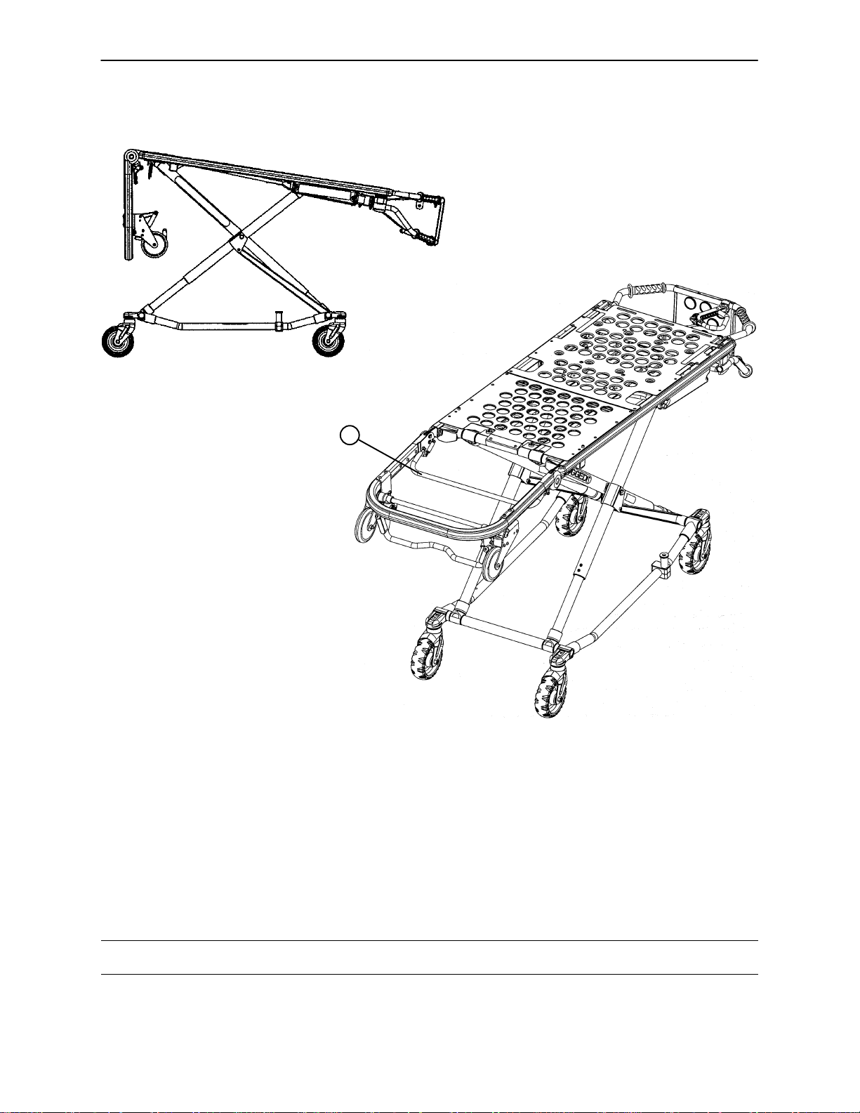
Operating Breakaway Head Section
A
NOTE
View has the head section
skin removed for clarity.
The head end of the cot litter folds down to shorten the length of the cot and allow for maneuvering when space
is limited in elevators, halls, etc.
The breakaway head section should only be used when the cot is in positions 5–8 (see page 12).
To lower the breakaway head section, squeeze the release bar (A) at the head end of the cot with one hand
while supporting the head section with the other hand. Lower the head section.
To raise the breakaway head section, lift the breakaway head section until the release bar clicks and the
head section locks into place.
CAUTION
Damage to the cot can occur if the cot is lowered in the shortened position. Use only positions 5–8 (see page
12) when the cot is shortened.
17
Page 20
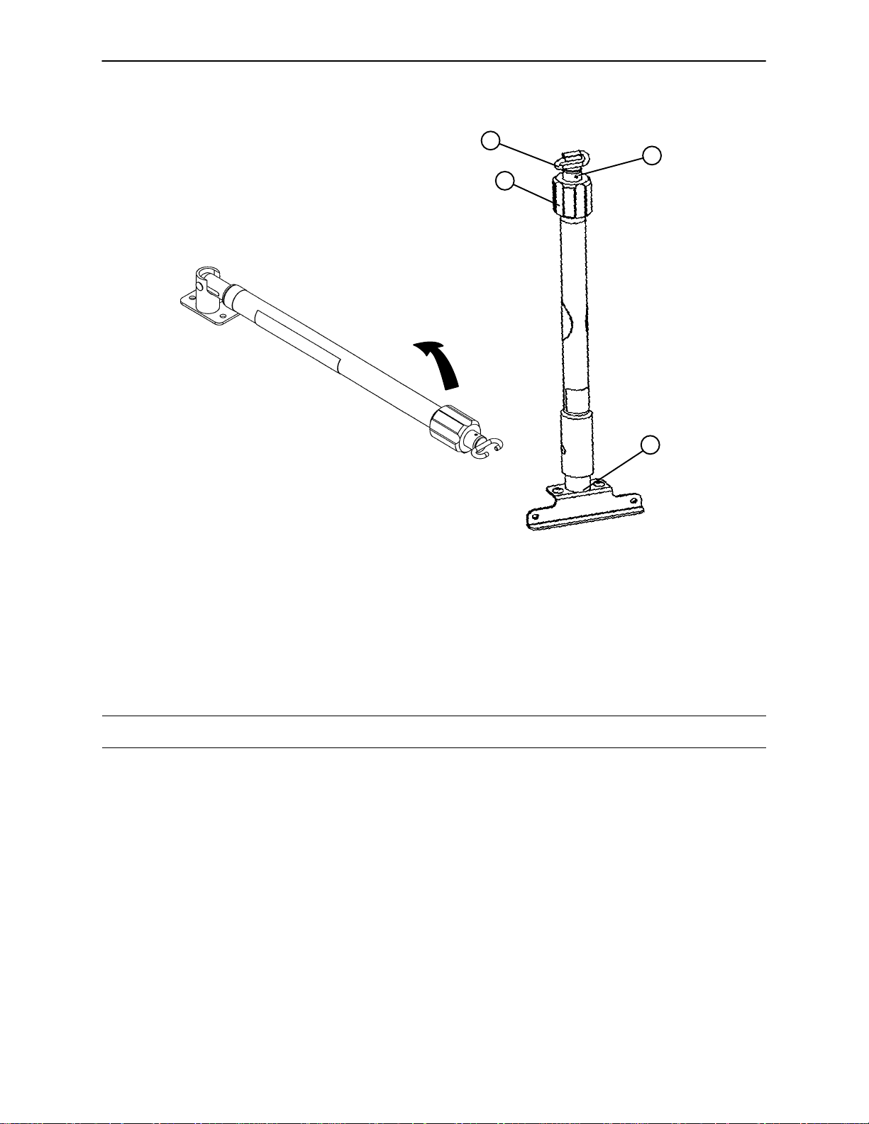
Operating 2–Stage I.V. Pole
Storage Position
Cot Operation
D
C
B
A
1. Lift and pivot the pole from the storage position and push down until it is locked into receptacle (A).
2. To raise the height of the pole, turn the lock actuator (B) counterclockwise and pull up on the telescoping
portion (C) of the pole to raise it to the desired height.
3. Turn the lock actuator (B) clockwise to lock the telescoping portion in place.
4. Hang I.V. bags on the I.V. hook (D).
CAUTION
The weight of the I.V. bags should not exceed 40 pounds.
18
Page 21
Cot Operation
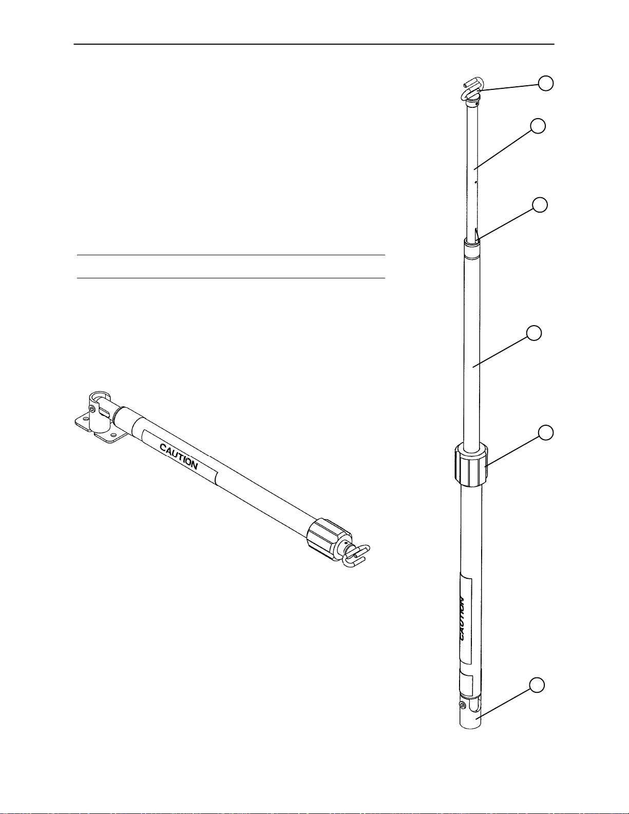
Operating 3–Stage I.V. Pole (Optional Equipment)
1. Lift and pivot the pole from the storage position and push down until
it is locked into receptacle (A).
2. To raise the height of the pole, turn the lock actuator (B) counterclockwise and pull up on the bottom telescoping portion (C) of the pole
to raise it to the desired height.
3. Turn the lock actuator (B) clockwise to lock the bottom telescoping
portion in place.
4. For a higher I.V. pole, pull up on section (D) until the spring clip (E)
engages.
5. Hang I.V. bags on the I.V. hook (F).
CAUTION
The weight of the I.V. bags should not exceed 40 pounds.
6. To lower the I.V . pole, push in on the spring clip (E) and slide section
(D) down into section (C). Turn the lock actuator (B) counterclockwise
and slide section (C) into the bottom tube.
7. Lift up and pivot the pole down into the storage position.
F
D
E
C
Storage Position
B
A
19
Page 22

Cot Operation
Removing/Installing the Incubator Adaptor/O2 Module
NOTE
The incubator adaptor may have been installed at the factory if the adaptor was ordered with the Rugged
IT Cot.
If the adaptor was purchased as a retrofit kit, follow these instructions for installation:
WARNING
These adaptors are intended for use only on the Model 6081 Rugged Incubator Transporter Cot. They are
not intended for installation on any other Rugged Cot or on any cot from another manufacturer. Using these
adaptors on any cot other than the Rugged Model 6081 may result in damage to the cot and/or injury to
the patient or user.
1. Remove the existing adaptor if there is one already present. Refer to the chart below to locate the pages
for removal and installation instructions for each adaptor.
INCUBATOR/MODULE PAGE REQUIRED TOOL(S)
Airborne 45 5/32, 3/16 Allen Wrench
Air–Shields 47 5/32, 3/16 Allen Wrench
Ohmeda Air–Vac 49 5/32 Allen Wrench
Airborne O Module 50.1 1/2” Socket & Ratchet
2. Install the new incubator adaptor. Refer to the chart above to locate the pages with removal and installa-
tion instructions for each adaptor.
3. Align the adaptor assembly with the mounting holes in the Rugged IT Cot as shown in the appropriate
illustration.
4. Reference the appropriate illustration to determine the correct location for installation of the provided fas-
teners. Apply a few drops of the provided Loctite to the threads of the fasteners and tighten them securely.
5. Install the incubator on the adaptor. Refer to the chart below to locate the pages for installation instruc-
tions for each incubator.
INCUBATOR/MODULE PAGE
Airborne 21
Air–Shields 22 & 23
Ohmeda Air–Vac 24
Airborne O Module 24.1
WARNING
Verify the adaptor is properly installed on the cot and the incubator is securely fastened to the adaptor prior
to use. An improperly attached adaptor or incubator may cause injury to the patient or user.
20
Page 23

Cot Operation
Installing the Airbornet Incubator on the Ruggedt IT Cot
Prior to installing the incubator on the Rugged IT Cot, read and understand this manual and the manual
supplied with the incubator.
WARNING
The Stryker Model 6081–200 adaptor is designed to secure only Airborne 20H incubators to the Model 6081
Rugged IT Cot. Using this adaptor on any cot other than the Rugged Model 6081 or using any unapproved
incubators on this adaptor may result in damage to the cot and/or injury to the patient or user.
B
A
B
A
SIDE VIEW
1. Push down on latch tab (A) to release latch tab (B).
2. Pull down on the latch tab (B) and open each of the latches on the four corners of the incubator.
3. Place the Airborne incubator into the adaptor on the cot. Verify all four corners of the incubator are
properly seated in the adaptor.
4. Insert each latch into its slot on the adaptor. Push up on the latch tab (B) to secure the latches. Verify
all four latches are securely fastened.
WARNING
Verify the adaptor is properly installed on the cot and the incubator is securely fastened to the adaptor prior
to use. An improperly attached adaptor or incubator may cause injury to the patient or user.
21
Page 24

Cot Operation
Installing the Air–Shields Incubator on the Ruggedt IT Cot
Prior to installing the incubator on the Rugged IT Cot, read and understand this manual and the manual
supplied with the incubator.
WARNING
The Stryker Model 6081–300 adaptor is designed to secure only Air–Shields incubators to the Model 6081
Rugged IT Cot. Using this adaptor on any cot other than the Rugged Model 6081 or using any unapproved
incubators on this adaptor may result in damage to the cot and/or injury to the patient or user.
The Stryker Model 6081–300 Air–Shields adaptor is designed to accommodate a 1999 or earlier model
TI100, TI500 and Globetrotter Series incubator. Stryker is not responsible for specification changes to the
Air–Shields TI100 Series incubator.
C
C
B
A
1. Pull out the red latch handle (A) on the adaptor and move it to the right until the slot in the handle engages
with the shoulder bolt (B) on the adaptor.
2. Place the incubator on the adaptor, aligning the holes in the incubator with the 4 pins (C – 2 of 4 shown)
on the adaptor.
22
Page 25

Cot Operation
Installing the Air–Shields Incubator on the Ruggedt IT Cot (Continued)
UNLOCKED POSITION LOCKED POSITION
3. Move the latch handle to the left to release it. The handle retracts and the latches engage, securing the
incubator. Inspect all four locking points to verify the latches are securely engaged and are not obstructed
by anything (hoses, wires, etc.).
WARNING
Verify the adaptor is properly installed on the cot and the incubator is securely fastened to the adaptor prior
to use. An improperly attached adaptor or incubator may cause injury to the patient or user.
23
Page 26

Cot Operation
Installing the Ohmeda Air–Vac Incubator on the Ruggedt IT Cot
Prior to installing the incubator on the Rugged IT Cot, read and understand this manual and the manual
supplied with the incubator.
WARNING
The Stryker Model 6081–100 adaptor is
designed to secure only Ohmeda Air–
Vac incubators to the Model 6081
Rugged IT Cot. Using this adaptor on
any cot other than the Rugged Model
6081 or using any unapproved incubators
on this adaptor may result in damage to
the cot and/or injury to the patient or user.
VIEW 1
VIEW 2
1. Verify the locking knob is retracted
(view 1).
2. Place the Ohmeda Air–Vac
incubator on the adaptor. Be sure
the “L” shaped mounting tabs align
properly with the mounting rail (views
1 & 2).
3. Slide the incubator to the head
end of the cot so the mounting
tabs mate with the mounting rail
(view 3).
4. Tighten the locking knob securely
against the incubator (view 3).
WARNING
Verify the adaptor is properly installed on
the cot and the incubator is securely fastened to the adaptor prior to use. An improperly attached adaptor or incubator
may cause injury to the patient or user.
VIEW 3
24
Page 27

Cot Operation
Installing the Airbornet O2 Bottle Module on the Ruggedt IT Cot
Prior to installing the Airborne O Bottle Module on the Rugged IT Cot, read and understand this manual
and the manual supplied with the O module.
WARNING
The Stryker Model 6081–201 adaptor is designed to secure only Airborne O Bottle Modules to the Model
6081 Rugged IT Cot. Using this adaptor on any cot other than the Rugged Model 6081 or using any unapproved incubators or O modules on this adaptor may result in damage to the cot and/or injury to the patient
or user.
C
A
A
B
B
HEAD END
1. Using a 1 / 2 ” socket and ratchet, remove the four 5/16” hex nuts and washers (A) from the mounting studs
(B) on the adaptor.
2. Locate the mounting holes in the bottom of the O bottle module (C).
3. Install the O bottle holder on the adaptor mounting studs (B) with the bottle openings toward the breakaway head section. Verify all four mounting studs are properly seated in the mounting holes of the O
bottle holder.
4. Using a 1 / 2 ” socket and ratchet, install the four 5/16” hex nuts and washers (A) removed in step one and
tighten them securely.
WARNING
Verify the adaptor is properly installed on the cot and the O module is securely fastened to the adaptor prior
to use. An improperly attached adaptor or O module may cause injury to the patient or user.
24.1
Page 28

Notes
24.2
Page 29

Cleaning
Hand wash all surfaces of the cot with warm water and mild detergent. Dry thoroughly. DO NOT STEAM
CLEAN, PRESSURE WASH, HOSE OFF OR ULTRASONICALLY CLEAN. Using these methods of cleaning
is not recommended and may void this product’s warranty.
In general, when used in those concentrations recommended by the manufacturer, either phenolic type or
quaternary type disinfectants can be used. Iodophor type disinfectants are not recommended for use because staining may result. The following products have been tested and have been found not to have a harmful effect WHEN USED IN ACCORDANCE WITH MANUFACTURERS RECOMMENDED DILUTION.*
TRADE NAME
A33 Quaternary Airwick (Professional Products Division) 2 ounces/gallon
A33 (dry) Quaternary Airwick (Professional Products Division) 1/2 ounce/gallon
Beaucoup Phenolic Huntington Laboratories 1 ounce/gallon
Blue Chip Quaternary S.C. Johnson 2 ounces/gallon
Elimstaph Quaternary Walter G. Legge 1 ounce/gallon
Franklin
Phenomysan F2500
Franklin Sentinel Quaternary Purex Corporation 2 ounces/gallon
Galahad Phenolic Puritan Churchill Chemical Company 1 ounce/gallon
Hi–Tor Quaternary Huntington Laboratories 1/2 ounce/gallon
LPH Phenolic Vestal Laboratories 1/2 ounce/gallon
Matar Phenolic Huntington Laboratories 1/2 ounce/gallon
Omega Quaternary Airwick (Professional Products Division) 1/2 ounce/gallon
Quanto Quaternary Huntington Laboratories 1 ounce/gallon
Sanikleen Quaternary West Chemical Products 2 ounces/ gallon
Sanimaster II Quaternary Service Master 1 ounce/gallon
Vesphene Phenolic Vestal Laboratories 1 1/4 ounce/ gallon
DISINFECTANT
Phenolic Purex Corporation 1 1/4 ounce/gallon
TYPE
MANUFACTURER
*MANUFACTURER’S
RECOMMENDED
DILUTION
Quaternary Germicidal Disinfectants, used as directed, and/or Chlorine Bleach products, typically 5.25% So dium Hypochlorite in dilutions ranging between 1 part bleach to 100 parts water, and 2 parts bleach
to 100 parts water are not considered mild detergents. These products are corrosive in nature and may
cause damage to your stretcher if used improperly. If these types of products are used to clean Stryker patient
handling equipment, measures must be taken to insure the stretchers are rinsed with clean water and thoroughly dried following cleaning. Failure to properly rinse and dry the stretchers will leave a corrosive residue
on the surface of the stretcher, possibly causing premature corrosion of critical components.
NOTE
Failure to follow the above directions when using these types of cleaners may void this product’s warranty.
REMOVAL OF IODINE COMPOUNDS
1. Use a solution of 1–2 tablespoons Sodium Thiosulfate in a pint of warm water to clean the stained area.
Clean as soon as possible after staining occurs. If stains are not immediately removed, allow solution to
soak or stand on the surface. Rinse surfaces which have been exposed to the solution in clear water before returning unit to service.
25
Page 30

Preventative Maintenance
Operation
Cleaning & Disinfecting Each use. See page 25.
Inspection For 1 – 25 calls per month, inspect
NOTE
Keep up–to–date maintenance records using the form on page 27.
Parts, Service or Technical Assistance:
Contact Stryker Customer Service at 1–800–327–0770 or
Stryker Medical
6300 Sprinkle Road
Kalamazoo, MI 49001
ATTN: Customer Service
Schedule Procedure
See below for checklist.
cot every 6 months
For 26+ calls per month, inspect
cot every 3 months
A visual inspection of all major cot
functions should be performed
prior to each use.
CHECKLIST
All fasteners secure (reference all assembly prints)
All welds intact, not cracked or broken
No bent or broken tubing or sheet metal
No debris in wheels
All wheels secure, rolling and swivelling properly
Optional accessories intact and operating properly
Height positioning latch functioning properly
Cot secure in each height position
Undercarriage folds properly
Breakaway head section operating properly
Safety bar operating properly
Incubator adaptor attachment hardware intact
Incubator adaptor latches working properly
Serial No.______________
Completed By:_________________________________ Date:_____________
26
Page 31

Maintenance Record
Date Maintenance Operation Performed By
27
Page 32

Training Record
Training Date Training Method
Trainee Name Basic
Training
Refresher
Update
Owner’s Manual, In–Service,
Formal Class, Etc.
28
Page 33

Notes
29
Page 34

Cot Assembly
Assembly part number 6081–1–11 (reference only)
30
Page 35

Cot Assembly
(SOME PARTS REMOVED FOR CLARITY)
31
Page 36

Cot Assembly
Item Part No. Part Name Qty.
A4–135 H. Soc. But. Hd. Cap Scr. 2
B4–198 H. Soc. But. Hd. Cap Scr. 4
C4–232 H. Soc. But. Hd. Cap Scr. 6
D11–355 Flat Washer 2
E16–28 Fiberlock Nut 10
F25–79 Pop Rivet 2
G38–348 Extension Spring 2
H 6060–37–26 Spacer Plate 2
J 6060–37–35 End Cap 2
K 6060–90–2 Serial Number Tag 1
L 6060–90–3 Large “Rugged” Label 2
M 6060–90–4 Small “Rugged” Label 2
N 6060–90–114 “Hands Clear” Label 4
P (page 33 & 34) Base Assembly 1
R (page 38 & 39) Litter Assembly 1
S 6080–30–43 Litter Frame Bumper 2
T 6080–33–36 Retainer Plate Cover, Lt. 1
U 6080–33–37 Retainer Plate Cover, Rt. 1
V (page 42 & 43) Breakaway Head Ass’y1
W (page 44) Release Handle Ass’y2
X 6080–40–44 Link Release Spacer 2
Y 6080–90–106 “500 LB. Max.” Label 2
Z 6080–90–108 “Lift Here” Label 2
AA 6080–90–9 “Damage Warning” Label 1
AB 6081–90–110 “ITMX–Pro” Label 2
AC 6081–90–37 Specification Label 1
32
Page 37

Base Assembly
33
Page 38

Detail 1
Outer Tube
Base Assembly
Detail 2
Inner Tube
Item Part No. Part Name Qty. Item Part No. Part Name Qty.
A3–353 Hex Hd. Cap Screw 4 AH 6060–1–57 B. Piv. Out. Lift Tube Wldmt. 2
B3–205 Hex Hd. Cap Screw 4 AJ 6060–1–59 B. Piv. In. Lift Tube Wldmt. 2
C4–135 H. Soc. But. Hd. Cap Scr. 2 AK 6060–1–70 Upper Frame Tube Bearing 8
D4–163 H. Soc. But. Hd. Cap Scr. 3 AL 6060–1–71 Lower Frame Tube Bearing 8
E4–198 H. Soc. But. Hd. Cap Scr. 6 AM (page 36) Wheel Assembly 4
F4–204 H. Soc. But. Hd. Cap Scr. 1 AN 6060–2–12 Caster Horn Assembly 4
G4–232 H. Soc. But. Hd. Cap Scr. 1 AQ 6060–4–43 Retaining Post Cap 1
H4–234 H. Soc. But. Hd. Cap Scr. 2 AR 6060–4–44 Retaining Post Tube 1
J8–28 Soc. Hd. Shoulder Bolt 3 AS 6060–5–29 Ht. Adj. Rack Mtg. Pivot 2
K8–45 Hex Soc. Shoulder Bolt 2 AT 6060–5–32 Height Adjustment Bar 2
L11–350 Nylon Washer 4 AU 6060–5–37 Spacer Link Spacer 5
N11–4 Flat Washer 4 AV 6060–5–38 Spacer Link 2
P16–28 Fiberlock Hex Nut 12 AW 6060–5–42 Lower Ht. Adjustment Rack 2
Q16–35 Nylock Hex Nut 2 AX 6060–5–43 Upper Ht. Adjustment Rack 2
R 6090–1–9 Caster Nut 4 AY 6060–5–44 Lock Bar Slide Bearing 2
S16–60 Centerlock Nut 4 AZ 6080–1–29 Outer Base Spacer, Hd. End 2
T16–89 Centerlock Nut 2 BA 6080–1–43 Base Tube 2
U25–128 Flange Rivet 4 BB 6080–1–46 Support Link 2
V25–133 Dome Hd. Rivet 12 BC 6080–5–26 Side Release Handle 1
W37–204 Hole Plug 4 BD 6080–5–34 Mounting Bracket 2
X81–244 Flange Bearing 16 BF (page 37) Lock Bar Assembly 1
Y 6060–101–15 Outer Base Tube Ass’y 2 BG 6080–4–45 Ret. Post Casting, Top 1
Z 6060–1–21 Caster Mount Cover 4 BH 6080–4–46 Ret. Post Casting, Bottom 1
AA 6060–1–27 Connecting Rod Bearing 4 BJ 6080–40–22 Upper Link 1
AB 6060–101–28 Connecting Rod 1 BK 6080–40–23 Lower Link 1
AC 6060–1–30 Center Base Spacer 1 BM 6081–5–51 Pivot Tube 1
AD 6060–1–31 Inner Base Spcr., Ft. End 1 BN 721–31–65 Hole Plug 1
AE 6060–1–32 Inner Base Spcr., Hd. End 1 BP 6080–40–25 Link Bushing 4
AF 6060–201–53 Lit. Piv. Out. Lift T. Wldmt. 2 BQ 6080–40–88 Link Bracket 1
AG 6060–101–55 Lit. Piv. In. Lift Tube Wldmt. 2 BR 946–1–73 Stryker Logo Label 2
34
Page 39

Base Assembly
FRAME GUARD OPTION 6080–145
Item Part No. Part Name Qty.
FA 6080–145–1 Upper Frame Guard 2
FB 6080–145–2 Lower Frame Guard 2
FC 16–111 Hex Nut 8
FD 4–215 Hex But. Hd. Cap Scr. 8
35
Page 40

6060–2–10 Wheel Assembly
Item Part No. Part Name Qty.
A81–226 Bearing 2
B 715–1–255 Wheel Bushing 2
36
Page 41

6080–5–56 Lock Bar Assembly
Item Part No. Part Name Qty.
A 6080–5–55 Lock Bar 1
B 6060–5–96 Latch Pin 2
C 6080–5–36 Wear Ring 2
D81–248 Bearing 4
E28–181 Retaining Ring 2
37
Page 42

6080–157 Optional Base Lift Bar Assembly
Item Part No. Part Name Qty.
A4–135 Hex Soc. But. Hd. Cap Screw 4
B16–28 Nylock Hex Nut 4
C37–202 Tube Plug 2
D 6080–157–13 Breakaway Lift Bar Weldment 1
37.1
Page 43

Notes
37.2
Page 44

Litter Assembly
Assembly part number 6081–30–11 (reference only)
38
Page 45

Litter Assembly
Item Part No. Part Name Qty.
A4–97 Hex Soc. But. Hd. Cap Scr. 6
B4–135 Hex Soc. But. Hd. Cap Scr. 4
C4–163 Hex Soc. But. Hd. Cap Scr. 4
D4–161 Hex Soc. But. Hd. Cap Scr. 8
E4–197 Hex Soc. But. Hd. Cap Scr. 6
G4–215 Hex Soc. But. Hd. Cap Scr. 4
H16–3 Fiberlock Hex Nut 4
J16–28 Fiberlock Hex Nut 6
K16–78 Centerlock Hex Nut 4
L18–38 Umbrella Nut 4
M25–79 Dome Head Rivet 27
N 721–31–65 Hole Plug 4
P 6060–25–33 Pivot Mount Spacer 2
R 6080–30–38 Foot End Litter Stop 2
S 6080–30–40 Litter Stop 2
T 6080–30–42 Cross Brace 2
U 6081–30–46 Outer Support Rail, Rt. 1
V 6081–30–47 Outer Support Rail, Lt. 1
W 6080–33–32 Slide Plate, Left 1
X 6080–33–33 Slide Plate, Right 1
Y 6081–34–46 Midsection Skin 1
Z 6081–38–45 Foot Section Skin 1
AA 6080–39–43 Lift Bar Plug 4
AB 6080–40–11 Grip 4
AC 6080–40–12 Outer Rail End Cap, Foot 2
AD 6080–240–30 Lift Bar Brace 1
AE (page 40) Upper Lift Tube Ass’y1
AF (page 41) Lower Lift Tube Assembly 1
AG 6081–25–33 Large Insert 2
39
Page 46

6080–40–51 Upper Lift Tube Assembly
Item Part No. Part Name Qty.
A25–79 Rivet 4
B 6080–40–18 Upper Lifting Bar 1
C 6080–40–38 Release Handle Pivot 1
40
Page 47

6080–40–52 Lower Lift Tube Assembly
Item Part No. Part Name Qty.
A25–79 Rivet 4
B 6080–40–19 Lower Lifting Bar 1
C 6080–40–38 Release Handle Pivot 1
41
Page 48

Breakaway Head Assembly
Assembly part number 6080–37–55 (reference only)
Item Part No. Part Name Qty. Item Part No. Part Name Qty.
A4–163 H. Soc. But. Hd. Cap Scr. 4 T 6060–37–26 Pivot Spacer Plate 2
B4–197 H. Soc. But. Hd. Cap Scr. 4 U 6060–37–33 Horn Stop Block 2
C4–204 H. Soc. But. Hd. Cap Scr. 9 V 6060–37–36 Trigger Lock Spacer 2
D4–222 H. Soc. But. Hd. Cap Scr. 2 W 6060–37–37 Pivot Cover, Right 1
E4–231 H. Soc. But. Hd. Cap Scr. 4 X 6060–37–38 Pivot Cover, Left 1
F4–310 But. Hd. Cap Screw 2 Y 6080–36–44 Bumper 1
G4–54 But. Hd. Cap Screw 2 Z 6080–36–45 Outer Rail 1
H16–3 Fiberlock Hex Nut 2 AA 6080–37–27 Outer Caster Horn, Left 1
J16–28 Fiberlock Hex Nut 12 AB 6080–37–28 Outer Caster Horn, Right 1
K16–78 Centerlock Hex Nut 7 AC 6080–37–29 Inner Caster Horn, Left 1
L16–20 Centerlock Hex Nut 2 AD 6080–37–30 Inner Caster Horn, Right 1
M26–269 Clevis Pin 2 AE 6080–37–34 Safety Hook Pivot Tube 1
N28–138 Retaining Ring 4 AF 6080–37–49 Release Handle Spacer 2
P38–410 Extension Spring 2 AG 6090–37–39 Trigger Lock 2
R 6060–36–20 Five Inch Wheel Ass’y 2 AH 6090–37–42 Pivot Form, Right 2
S 6060–36–24 Pivot Stop Pin 2 AJ 6090–37–43 Pivot Form, Left 2
42
Page 49

Breakaway Head Assembly
Safety Hook Option
Assembly part number 6091–156–10
Lift Option
Assembly part number 6091–156–16
(reference only)
Assembly part number 6081–37–10
(reference only)
Item Part No. Part Name Qty. Item Part No. Part Name Qty.
EA 25–79 Rivet 2 JH 38–408 Torsion Spring 1
EB 28–138 Retaining Ring 2 JJ 38–409 Torsion Spring 1
EC 6060–37–40 Center Pivot 4 JK 721–26–66 Pivot Screw 1
ED 6080–36–25 Pivot Pin 2 JL 6060–37–21 Safety Hook Pivot 2
EE 6080–36–47 Bent Release Crossbar 1 JM 6060–37–47 Safety Hook Rel. Handle 1
EF 6080–37–55 Breakaway Head Ass’y 1 JN 6080–237–48 Safety Hook Release Arm 1
EG 6081–37–45 Breakaway Head Skin 1 LD 6080–37–22 Hook Tube 1
EH 6081–91–57 40 Lb. Max. Caution Label 2
JA 4–135 H. Soc. But. Hd. Cap Scr. 2 6091–156–16 Lift Option
JB 4–136 Pan Hd. Mach. Screw 1 LA 4–440 But. Hd. Cap Screw 2
JC 4–204 Hex Soc. But. Hd. Cap Scr. 3 LB 25–157 Dome Head Rivet 2
JD 11–65 Flat Washer 1 LC 56–19 Bumper 2
JE 11–179 Flat Washer 1 LD 6080–37–23 Lift Capable Hook Tube 1
JF 16–28 Fiberlock Hex Nut 4 LE 6091–160–21 Lift Nub, Left 1
JG 16–78 Centerlock Hex Nut 1 LF 6091–160–22 Lift Nub, Right 1
43
Page 50

6080–40–40 Release Handle Assembly
Item Part No. Part Name Qty.
A25–125 Rivet 2
B 6080–40–41 Release Handle Link 1
E 6080–40–50 Side Release Handle Ass’y1
44
Page 51

6081–200–10 Airbornet Adaptor Mounting Assembly
Item Part No. Part Name Qty.
A4–117 Soc. Hd. Cap Screw 4
B4–135 Button Hd. Cap Screw 2
C4–218 Button Hd. Cap Screw 2
D (page 46) Adaptor Assembly 1
45
Page 52

6081–200–10 Airbornet Incubator Adaptor Assembly
Label Locations
Item Part No. Part Name Qty.
E4–142 Soc. Hd. Cap Screw 4
F16–28 Nylock Nut 4
G25–79 Pop Rivet 2
H 6060–90–2 Serial Number Tag 1
J 6081–91–202 Specification Label 1
K 6081–91–201 Warning Label 2
L 6081–100–20 Frame Weldment 1
M 6081–200–20 Mounting Angle 2
N 6081–200–22 Mounting Wedge 4
46
Page 53

6081–300–10 Air–Shields) Adaptor Mounting Ass’y
Item Part No. Part Name Qty.
A4–135 But. Hd. Cap Screw 6
B4–218 But. Hd. Cap Screw 2
C (page 48) Adaptor Assembly 1
47
Page 54

6081–300–10 Air–Shields) Incubator Adaptor Ass ’y
Item Part No. Part Name Qty. Item Part No. Part Name Qty.
A1–105 Flat Hd. Machine Screw 1 U 6081–90–302 Specification Label 1
E4–325 But. Hd. Cap Screw 6 V 6081–90–303 Lock Pull Label 1
F8–49 Shoulder Bolt 2 W 6081–91–301 Warning Label 2
G8–51 Shoulder Bolt 4 X 6081–100–20 Frame Weldment 1
H11–64 Washer 2 Y 6081–300–20 Slide Bar 2
J11–193 Washer 4 Z 6081–300–21 Pivot Bar 1
K11–423 Plastic Spacer 1 AA 6081–300–22 Lock Block 4
L11–445 Washer 4 AB 6081–300–23 Pull Handle 1
M14–19 Nylon Washer 7 AC 6081–300–24 Hex Pin 4
N16–28 Nylock Nut 2 AD 4–278 But. Hd. Cap Screw 1
P25–79 Pop Rivet 2 AE 6081–25–35 Pivot Sleeve 1
R38–453 Extension Spring 2 AF 16–3 Nylock Nut 1
S 715–1–333 Sleeve 1 AG 8–15 Shoulder Bolt 1
T 6060–90–2 Serial Number Tag 1
48
Page 55

6081–100–10 Ohmeda) Adaptor Mounting Assembly
Item Part No. Part Name Qty.
A4–117 Soc. Hd. Cap Screw 2
B4–135 But. Hd. Cap Screw 4
C4–339 Soc. Hd. Cap Screw 2
D (page 50) Adaptor Assembly 1
49
Page 56

6081–100–10 Ohmeda) Incubator Adaptor Assembly
Label Locations
Item Part No. Part Name Qty.
B4–130 But. Hd. Cap Screw 2
D4–142 Soc. Hd. Cap Screw 12
E4–149 But. Hd. Cap Screw 1
G11–64 Washer 1
H16–11 Nylock Nut 2
J16–28 Nylock Nut 12
K24–66 Male Knob 1
L25–79 Pop Rivet 2
M 6060–37–36 Sleeve 1
N 6060–90–2 Serial Number Tag 1
P 6081–90–102 Specification Label 1
R 6081–91–101 Warning Label 2
S 6081–100–20 Frame Weldment 1
T 6081–100–26 Wear Plate 4
U 6081–100–27 Stop Block 4
V 6081–100–28 Wedge Block, Right 2
W 6081–100–29 Wedge Block, Left 2
X 6081–100–30 Knob Block 1
Y 6081–100–31 Knob Pusher 1
Z 6081–100–32 Friction Pad 1
50
Page 57

6081–201–10 Airbornet O2 Module Adaptor Mtg. Ass’y
Item Part No. Part Name Qty.
A4–135 But Hd. Cap Screw 6
B4–218 But. Hd. Cap Screw 2
C (page 50.2) O2 Module Adaptor Ass’y1
50.1
Page 58

6081–201–10 Airbornet O2 Module Adaptor Assembly
Item Part No. Part Name Qty.
A11–77 Flat Washer 4
B11–447 Flat Washer 4
C16–11 Nylock Nut 4
D16–28 Nylock Nut 4
E25–79 Pop Rivet 2
F 6060–90–2 Serial Number Tag 1
G 6081–92–201 Warning Label 2
H 6081–93–201 Specification Label 1
J 6081–100–20 Frame Weldment 1
K 6081–201–20 Mounting Stud 4
50.2
Page 59

6080–210–10 Optional 2–Stage I.V. Mounting Ass’y, Rt.
6080–215–10 Optional 3–Stage I.V. Mounting Ass’y, Rt.
6080–210–10 6080–215–10
Item Part No. Part Name Qty. Item Part No. Part Name Qty.
A 6070–110–32 I.V. Retainer Plate 1 A 6070–110–32 I.V. Retainer Plate 1
B 6080–110–35 I.V. Clip 1 B 6080–110–35 I.V. Clip 1
C (page 52) 2–Stage I.V. Pole, Right 1 C (page 53) 3–Stage I.V. Pole, Right 1
D16–78 Centerlock Hex Nut 4 D 16–78 Centerlock Hex Nut 4
E4–97 Hex Soc. But. Hd. Cap Scr. 2 E 4–97 Hex Soc. But. Hd. Cap Scr. 2
F4–163 Hex Soc. But. Hd. Cap Scr. 2 F 4–163 Hex Soc. But. Hd. Cap Scr. 2
G4–197 Hex Soc. But. Hd. Cap Scr. 2 G 4–197 Hex Soc. But. Hd. Cap Scr. 2
51
Page 60

6080–210–20 2–Stage I.V. Assembly, Patient Right
Item Part No. Part Name Qty.
A 6070–90–105 Caution Label 1
B (page 57) 2–Stage I.V. Pole Assembly 1
C 6070–210–45 I.V. Pole Sleeve 1
D 6070–210–46 I.V. Pivot 1
E 6070–210–49 I.V. Pivot Ring 1
F 6080–210–52 I.V. Socket Weldment, Right 1
G 6090–90–31 Specification Label 1
H25–133 Blind Rivet 2
52
Page 61

6080–215–20 3–Stage I.V. Assembly, Patient Right
Item Part No. Part Name Qty.
A 6070–90–105 Caution Label 1
B 6070–210–45 I.V. Pole Sleeve 1
C 6070–210–46 I.V. Pivot 1
D 6070–210–49 I.V. Pivot Ring 1
E (page 58) 3–Stage I.V. Pole Assembly 1
F 6080–90–33 Specification Label 1
G 6080–210–52 I.V. Socket Weldment, Right 1
H25–133 Blind Rivet 2
53
Page 62

6080–211–10 Optional 2–Stage I.V. Mounting Ass’y, Left
6080–216–10 Optional 3–Stage I.V. Mounting Ass’y, Left
6080–211–10 6080–216–10
Item Part No. Part Name Qty. Item Part No. Part Name Qty.
A 6070–110–32 I.V. Retainer Plate 1 A 6070–110–32 I.V. Retainer Plate 1
B 6080–110–35 I.V. Clip 1 B 6080–110–35 I.V. Clip 1
C (page 55) 2–Stage I.V. Pole, Left 1 C (page 56) 3–Stage I.V. Pole, Left 1
D16–78 Centerlock Hex Nut 4 D 16–78 Centerlock Hex Nut 4
E4–97 H. Soc. But. Hd. Cap Scr. 2 E 4–97 H. Soc. But. Hd. Cap Scr. 2
F4–163 H. Soc. But. Hd. Cap Scr. 2 F 4–163 H. Soc. But. Hd. Cap Scr. 2
G4–197 H. Soc. But. Hd. Cap Scr. 2 G 4–197 H. Soc. But. Hd. Cap Scr. 2
54
Page 63

6080–211–20 2–Stage I.V. Assembly, Patient Left
Item Part No. Part Name Qty.
A 6070–90–105 Caution Label 1
B (page 57) 2–Stage I.V. Pole Assembly 1
C 6070–210–45 I.V. Pole Sleeve 1
D 6070–210–46 I.V. Pivot 1
E 6070–210–49 I.V. Pivot Ring 1
F 6080–90–32 Specification Label 1
G 6080–211–52 I.V. Socket Weldment, Left 1
H25–133 Blind Rivet 2
55
Page 64

6080–216–20 3–Stage I.V. Assembly, Patient Left
Item Part No. Part Name Qty.
A 6070–90–105 Caution Label 1
B 6070–210–45 I.V. Pole Sleeve 1
C 6070–210–46 I.V. Pivot 1
D 6070–210–49 I.V. Pivot Ring 1
E (page 58) 3–Stage I.V. Pole Assembly 1
F 6080–90–34 Specification Label 1
G 6080–211–52 I.V. Socket Weldment, Left 1
H25–133 Blind Rivet 2
56
Page 65

6070–210–40 2–Stage I.V. Pole Assembly
Item Part No. Part Name Qty.
A 1210–110–46 Back–Up Ring 1
B 1210–110–47 Lock Ring 1
C 1210–110–49 Molded Actuator 1
D 6070–210–41 Base Tube 1
E 6070–110–42 2nd Stage Tube 1
F 6070–110–44 2nd Stage Slide Plug 1
G 6070–110–50 Hook Weldment 1
H26–6 Roll Pin 2
57
Page 66

6070–215–40 3–Stage I.V. Pole Assembly
Item Part No. Part Name Qty.
A 1210–110–46 Back–Up Ring 1
B 1210–110–47 Lock Ring 1
C 1210–110–49 Molded Actuator 1
D 6070–210–41 Base Tube 1
E 6070–110–44 2nd Stage Slide Plug 1
F 6070–110–50 Hook Weldment 1
G (page 59) 3rd Stage Assembly 1
H 6070–115–42 2nd Stage Tube 1
I 6070–115–45 Bearing Plug 1
J26–5 Spring Pin 1
K26–6 Spring Pin 1
58
Page 67

6070–115–30 3rd Stage Ass’y – Optional 3–Stage I.V. Pole
Item Part No. Part Name Qty.
A 6070–115–141 Spring Clip 1
B 6070–115–143 3rd Stage Tube 1
C 6070–115–44 3rd Stage Slide Plug 1
D26–4 Roll Pin 1
E45–139 O–Ring 1
59
Page 68

6080–155–20 Optional Pull Handle Assembly
Item Part No Part Name Qty.
A 6080–155–1 Pull Handle Bracket, Left 1
B 6080–155–2 Pull Handle Bracket, Right 1
C 6080–155–3 Pull Handle 1
D 721–26–69 Upright Sleeve 2
E25–79 Dome Hd. Rivet 4
F4–130 Hex Soc. But. Hd. Cap Screw 2
H16–36 Nylock Hex Nut 2
J23–133 Rivet 2
60
Page 69

Quick Reference Replacement Part Numbers
ITEM PART NUMBER
Bumper, Litter Foot Section 6080–30–43. . . . . . . . . . . . . . . . . . . . . . . . . . . . . . . . . . . . . . . . . . . .
Bumper, Litter Break–Away Head Section 6080–36–44. . . . . . . . . . . . . . . . . . . . . . . . . . . . . . .
Extension Spring, Height Adjustment 38–348. . . . . . . . . . . . . . . . . . . . . . . . . . . . . . . . . . .
Handle, Pull 6080–155–20. . . . . . . . . . . . . . . . . . . . . . . . . . . . . . . . . . . . . . . . . . . . . . . . . . . . . . . . .
Height Limit Kit 6060–202. . . . . . . . . . . . . . . . . . . . . . . . . . . . . . . . . . . . . . . . . . . . . . . . . . . . . .
Label, Cot Base ”Lift Here” 6080–90–8. . . . . . . . . . . . . . . . . . . . . . . . . . . . . . . . . . . . . . . . . . . .
Label, Cot I.V. Pole Caution 6070–90–5. . . . . . . . . . . . . . . . . . . . . . . . . . . . . . . . . . . . . . . . . . .
Label, Damage Warning 6080–90–9. . . . . . . . . . . . . . . . . . . . . . . . . . . . . . . . . . . . . . . . . . . . . .
Manual, Maintenance/Operations, IT Cot 6081–90–11. . . . . . . . . . . . . . . . . . . . . . . . . . . . . . . .
Manual, Installation/Operation, Cot Fastener 6370–90–10. . . . . . . . . . . . . . . . . . . . . . . . . . . .
Permanent I.V. Pole Kit, 2–Stage, Right 6080–210. . . . . . . . . . . . . . . . . . . . . . . . . . . . . . . . .
Permanent I.V. Pole Kit, 2–Stage, Left 6080–211. . . . . . . . . . . . . . . . . . . . . . . . . . . . . . . . . .
Permanent I.V. Pole Kit, 3–Stage, Right 6080–215. . . . . . . . . . . . . . . . . . . . . . . . . . . . . . . . .
Permanent I.V. Pole Kit, 3–Stage, Left 6080–216. . . . . . . . . . . . . . . . . . . . . . . . . . . . . . . . . .
Safety Hook, Long 6060–36–18. . . . . . . . . . . . . . . . . . . . . . . . . . . . . . . . . . . . . . . . . . . . . . . . . . .
Safety Hook, Short 6060–36–17. . . . . . . . . . . . . . . . . . . . . . . . . . . . . . . . . . . . . . . . . . . . . . . . . . .
Storage Net, Base 6080–150–10. . . . . . . . . . . . . . . . . . . . . . . . . . . . . . . . . . . . . . . . . . . . . . . . . . .
Touch–Up Paint (Yellow) 6060–199–10. . . . . . . . . . . . . . . . . . . . . . . . . . . . . . . . . . . . . . . . . . . . . .
Touch–Up Paint (Black) 6060–199–11. . . . . . . . . . . . . . . . . . . . . . . . . . . . . . . . . . . . . . . . . . . . . . .
Video, In–Service 6081–90–2. . . . . . . . . . . . . . . . . . . . . . . . . . . . . . . . . . . . . . . . . . . . . . . . . . . .
Wheel Assembly, Base 6060–2–10. . . . . . . . . . . . . . . . . . . . . . . . . . . . . . . . . . . . . . . . . . . . . . .
Wheel Bearing 81–226. . . . . . . . . . . . . . . . . . . . . . . . . . . . . . . . . . . . . . . . . . . . . . . . . . . . . . .
Wheel Mount Cover 6060–1–21. . . . . . . . . . . . . . . . . . . . . . . . . . . . . . . . . . . . . . . . . . . . . . . . . .
Wheel Mount Cover Rivet 25–133. . . . . . . . . . . . . . . . . . . . . . . . . . . . . . . . . . . . . . . . . . . . .
X–Frame Guard Option 6080–145. . . . . . . . . . . . . . . . . . . . . . . . . . . . . . . . . . . . . . . . . . . . . . .
61
Page 70

European Representative
Stryker France Phone: 33148632290
BP 50040–95946 Roissy Ch. de Gaulle Fax: 33148632175
Cedex–France
6300 Sprinkle Road, Kalamazoo, MI 49001–9799 (800) 327–0770
DH 9/00 6081–90–11 REV D
 Loading...