

Page 1
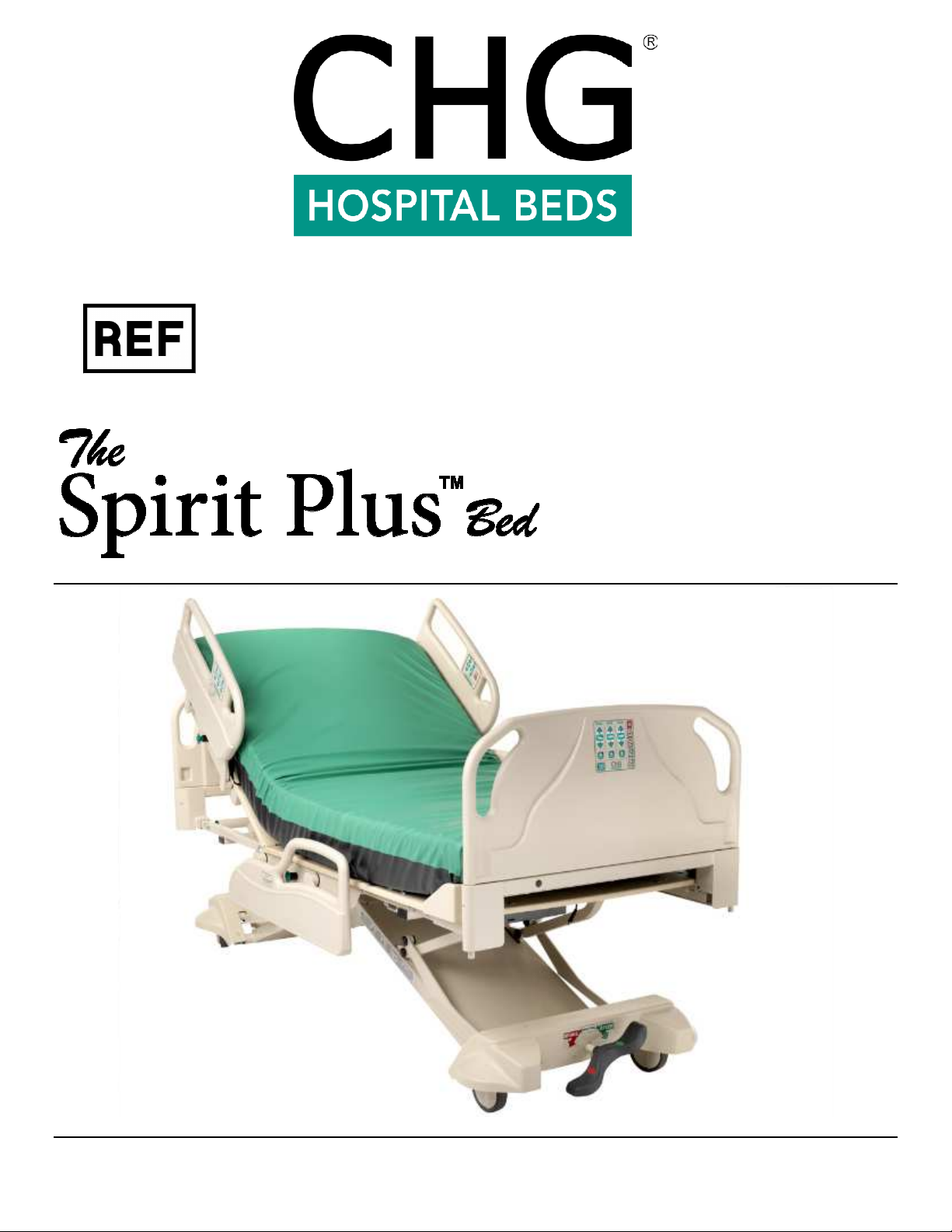
5600
1-70-008 – H
User Manual
Page 2

1-70-008 – H User Manual
- Spirit Plus 5600
CHG
Hospital
Beds
Page 2
of
103
Page 3
1-70-008 – H User Manual
- Spirit Plus 5600
CHG
Hospital
Beds
Page 3
of
103
Contact Information
Customer Service
Technical Service
or
Toll Free:
1 (800) 327-0770 USA
1 (800) 668-8323 Canada
CHG Hospital Beds
1020 Adelaide Street South
Mailing Address
London, Ontario N6E 1R6
Canada
To ensure prompt and accurate attention to your concerns please have the following
information available before you call:
Spirit Plus™ Service Call Information
Your facility’s phone number:
Your facility's fax number:
Bed(s) Model:
Bed(s) Serial Number
Date of Purchase:
List of defective part(s):
List of deficiencies or type of problem:
Page 4

1-70-008 – H User Manual
- Spirit Plus 5600
CHG
Hospital
Beds
Page 4
of
103
LED is flashing GREEN:
Bed is plugged into an AC power outlet and the battery is charging
GREEN and RED:
battery or another component. Service bed immediately
Spirit
To Operate the Bed:
Use the footboard staff control, rail controls, or the pendant to raise or lower the head section, the knee
section, or the entire bed.
To Operate Electronic CPR:
PRESS and HOLD the CPR button to flatten both the head and knee sections simultaneously.
To Operate Trendelenburg:
PRESS and HOLD the TREND (Trendelenburg) or rev.TREND (Reverse Trendelenburg) button on the
footboard control to achieve either function. To level the bed, PRESS and hold the opposite function until
the bed automatically stops in the horizontal position.
To Operate ‘Chair’:
PRESS and HOLD the CHAIR button. Green LED illuminates when full CHAIR position is achieved.
PRESS and HOLD CHAIR button again to level bed. If Green LED is not illuminated PRESS and HOLD
the CPR button to flatten both the head and knee sections and PRESS and HOLD the TREND button until
the bed automatically stops in the horizontal position.
To Operate ‘Auto Contour’:
Press the CONTOUR button so that the green light is on. Knee section will raise automatically when head
section is raised. (NOTE: KNEE lock-out will override Auto Contour).
Lock-Outs:
The side rail controls and pendant can be locked or unlocked (to restrict patient use). Lock-outs for each
bed function are located on the footboard staff control underneath each function. When the LOCK button
LED is illuminated, patient control of that particular function with the side rail controls or pendant is
restricted. If the LOCK button LED is not illuminated, then patient control of that function is permitted.
Master Lock-Out:
To restrict all side rail, pendant,
LOCK button LED’s will sequentially flash). When Master Lock-Out has been activated, the Electronic CPR
function and Nurse Call remains operable.
To Operate Plastic Siderails:
To lower the rails, gently depress the green PRESS button, then rotate the rail down. Head rails
rotate toward the headboard, foot rails rotate toward the footboard. The rail will automatically lock
in the UP position.
To Move and Lock the Bed:
Use the Central “Lock & Steer” system:
BRAKE: All four wheels are locked in “BRAKE” mode
STEER: Foot-end wheels are locked in “STEER” mode, head-end wheels swivel freely
NEUTRAL: All four wheels swivel freely in “NEUTRAL” mode
Power Status Indication:
LED is solid GREEN:
Plus™ Bed – Quick Reference Guide
and
footboard controls, press all three LOCK buttons simultaneously (the
Bed is plugged into an AC power outlet and the battery is fully charged
LED is solid RED: Bed is running on battery power
LED is flashing RED:
LED is alternating flashing
Bed is running on battery power but has used up the battery power.
Plug bed into an AC power outlet and allow battery to charge for 24 hr
Bed is plugged into an AC power outlet but there is a problem with the
Page 5

1-70-008 – H User Manual
- Spirit Plus 5600
CHG
Hospital
Beds
Page 5
of
103 1-70-008 – H User Manual
Page 6

- Spirit Plus 5600
CHG
Hospital
Beds
Page 6
of
103
Spirit Plus™ Bed User Instruction Manual Content
Page
Spirit Plus™ Bed – Quick Reference Guide ............................................................................................. 3
Section 1: ........................................................................................................................................ 8
Specifications & Precautions ........................................................................................................... 8
1.1 Full Bed Warranty ......................................................................................................................... 9
1.2 Intended Use .............................................................................................................................. 10
1.3 Standard Conventions Used in this Manual .................................................................................... 10
1.3.1 Patient Left & Patient Right Determination .......................................................................... 10
1.4 Symbols Used on the Spirit™ Bed ................................................................................................. 11
1.5 Technical Specifications ............................................................................................................... 12
1.6 Important Electrical Precautions ................................................................................................... 14
1.6.1 Battery Back-up ............................................................................................................... 16
1.6.2 Grounding ....................................................................................................................... 17
1.7 Important Mechanical Precautions ................................................................................................ 18
1.8 Mattress Specifications ................................................................................................................ 19
1.9 General Precautions .................................................................................................................... 20
1.10 Standard & Optional Features ...................................................................................................... 23
1.11 Siderail Assemblies ...................................................................................................................... 24
1.12 Optional Accessories.................................................................................................................... 24
1.13 Detachable Components .............................................................................................................. 25
1.14 Applied Parts .............................................................................................................................. 25
1.15 Storage & Transport .................................................................................................................... 25
1.16 Ultra-Low Feature ....................................................................................................................... 26
Section 2: ...................................................................................................................................... 27
Set-Up Instructions ....................................................................................................................... 27
2.1 Unpacking Instructions ................................................................................................................ 28
Section 3: ...................................................................................................................................... 40
Bed Operation ............................................................................................................................... 40
3.1 Central “Lock & Steer” System ..................................................................................................... 41
3.1.1 Bed Mobilization & Stabilization ......................................................................................... 42
3.2 Footboard Locking Mechanism ..................................................................................................... 43
3.3 Bed Control ................................................................................................................................ 44
3.3.1 Patient Handheld Control (Pendant) ................................................................................... 44
3.4 Bed Positioning ........................................................................................................................... 46
3.4.1 Bed Elevation – HI-LO Operation ....................................................................................... 46
3.4.2 Head Deck (Back Rest) Elevation - Head Actuator Operation ................................................ 46
3.4.3 Knee Deck Elevation - Foot Actuator Operation ................................................................... 47
3.4.4 Auto Contour Mode .......................................................................................................... 47
3.4.5 Chair Positioning .............................................................................................................. 48
3.5 Emergency & Staff Functions ....................................................................................................... 48
3.5.1 Electronic CPR (Cardiopulmonary Resuscitation) Function .................................................... 48
3.5.2 Trendelenburg Operation .................................................................................................. 49
3.5.3 Reverse Trendelenburg Operation ...................................................................................... 49
3.6 Patient Lock-Out Functions .......................................................................................................... 50
3.6.1 Regular Patient Lock-Outs ................................................................................................. 50
3.6.2 Master Lock-Out ............................................................................................................... 50
3.6.3 Security Lock-Out ............................................................................................................. 51
3.7 Other Bed Functions & Features ................................................................................................... 54
3.7.1 Nurse Call ........................................................................................................................ 54
Page 7

1-70-008 – H User Manual
- Spirit Plus 5600
CHG
Hospital
Beds
Page 7
of
103
3.7.2 Standard 37 Pin Connector ................................................................................................ 54
3.7.3 Spirit Plus™ Power Status Indicator ................................................................................... 55
3.8 Siderail Operation ....................................................................................................................... 56
3.8.1 Intended Application/Use of Spirit™ Bed Siderail Assemblies ................................................ 56
3.8.2 Plastic High Siderails ......................................................................................................... 57
3.8.3 Integrated Features of High Siderails ................................................................................. 58
3.8.4 Other Optional Siderails .................................................................................................... 59
3.9 Optional Underbed Light on Spirit Plus™ Beds ............................................................................... 59
3.10 Optional Underbed Obstruction Sensors ........................................................................................ 60
3.11 Optional “Easy Bed” Extension System .......................................................................................... 61
3.12 Optional Auxiliary AC Power Outlet ............................................................................................... 63
Section 4: ...................................................................................................................................... 64
Care & Maintenance ...................................................................................................................... 64
4.1 Regular Maintenance & Cleaning .................................................................................................. 65
4.1.1 Cleaning & Disinfection ..................................................................................................... 65
4.1.2 Semi Annual Inspections ................................................................................................... 66
4.1.3 Yearly Inspections & Maintenance...................................................................................... 66
4.2 Controls Servicing ....................................................................................................................... 68
4.2.1 Soft Reset of Controls ....................................................................................................... 68
4.2.2 Hard Reset of Controls ...................................................................................................... 68
4.3 Mattress Deck Removal ............................................................................................................... 69
4.3.1 Mattress Deck Removal - Foot Section................................................................................ 69
4.3.2 Accessing the CB10 Control Box ........................................................................................ 69
4.3.3 Mattress Deck Removal - Knee Section ............................................................................... 69
4.3.4 Mattress Deck Removal - Head Section (Back Rest) ................................................................... 70
4.3.5 Mattress Deck Removal - Seat Section................................................................................ 70
4.4 Rail Measurements ...................................................................................................................... 71
4.5 Before Calling The Factory ........................................................................................................... 72
4.6 Colour Information ...................................................................................................................... 72
4.7 Troubleshooting Guide ................................................................................................................ 73
4.8 Schematics & Technical ............................................................................................................... 76
4.8.1 Spirit Wiring Schematic ..................................................................................................... 76
4.8.2 Electrical Connections – Overview ...................................................................................... 78
4.8.3 Spirit Plus™ CB10Lite Control Box – Overview ..................................................................... 79
4.9 Electromagnetic Compatibility (EMC)............................................................................................. 80
4.10 Service Parts .............................................................................................................................. 85
Page 8

1-70-008 – H User Manual
- Spirit Plus 5600
CHG
Hospital
Beds
Page 8
of
103
Section 1:
Specifications & Precautions
Page 9

1-70-008 – H User Manual
- Spirit Plus 5600
CHG
Hospital
Beds
Page 9
of
103
1.1 Full Bed Warranty
Warranty
Stryker Medical, a division of Stryker Corporation, warrants to the original purchaser the Stryker Model 5600
Spirit Plus, to be free from defects in material and workmanship for a period of one year after date of delivery.
Stryker’s obligation under this warranty is expressly limited to supplying replacement parts and labor for, or
replacing at its option, any product which is, in the sole discretion of Stryker, found to be defective. If
requested by Stryker, product or parts for which a warranty claim is made shall be returned prepaid to the
factory. Any improper use or any alteration or repair by others in such a manner as in Stryker’s judgment
affects the product materially and adversely, shall void this warranty. Any repair of Stryker products using
parts not provided or authorized by Stryker shall void this warranty. No employee or representative of Stryker
is authorized to change this warranty in any way.
Stryker Medical products have a five year expected service life under normal use, conditions, and with
appropriate periodic maintenance as described in the maintenance manual for each device.
The above noted warranty periods apply only to the original purchaser of the Spirit Plus and begin on the date
of delivery to such original purchaser.
Warranty exclusion and damage limitations
The express warranty set forth herein is the only warranty applicable to the product. Any and all other
warranties, whether express or implied, including any implied warranty of merchantability or
fitness for a particular purpose are expressly excluded by Stryker. In no event shall Stryker be liable
for incidental or consequential damages.
To obtain parts and service
Stryker products are supported by a nationwide network of dedicated Stryker Field Service Representatives.
These representatives are factory trained, available locally, and carry a substantial spare parts inventory to
minimize repair time. Simply call your local representative or call Stryker Customer Service at 1-800-327 -0770
(USA) or 1-800-668-8323 (Canada).
Return authorization
Product cannot be returned without prior approval from the Stryker Customer Service Department. An
authorization number will be provided which must be printed on the returned product. Stryker reserves the
right to charge shipping and restocking fees on returned product. Special, modified, or discontinued products
are not subject to return.
Damaged product
ICC Regulations require that claims for damaged product must be made with within fifteen (15) days of receipt
of the product. Do not accept damaged shipments unless such damage is noted on the delivery receipt at the
time of receipt. Upon prompt notification, Stryker will file a freight claim with the appropriate carrier for
damages incurred. Claims will be limited in amount to the actual replacement cost. In the event that this
information is not received by Stryker within the fifteen (15) day period following the delivery of the product,
or the damage was not noted on the delivery receipt at the time of receipt, the customer will be responsible
for payment of the original invoice in full within thirty (30) days of receipt. Claims for any incomplete
shipments must be made within thirty (30) days of invoice.
International warranty clause
This warranty reflects U.S. domestic policy. Warranty outside the U.S. may vary by country. Contact your local
Stryker Medical representative for additional information.
Page 10
1-70-008 – H User Manual
- Spirit Plus 5600
CHG
Hospital
Beds
Page 10
of
103
1.2 Intended Use
The Spirit™ bed is intended for low to moderate acuity patients in the medical and/or surgical area of the
hospital. The Spirit™ bed is also intended for use as a general-purpose variable height hospital bed for general
care, post-operative and general medicine wards. The Spirit™ bed is intended for used in Application
Environments 1-3, 5 as described in IEC 60601-2-52, Clauses 201.3.201 - 205.
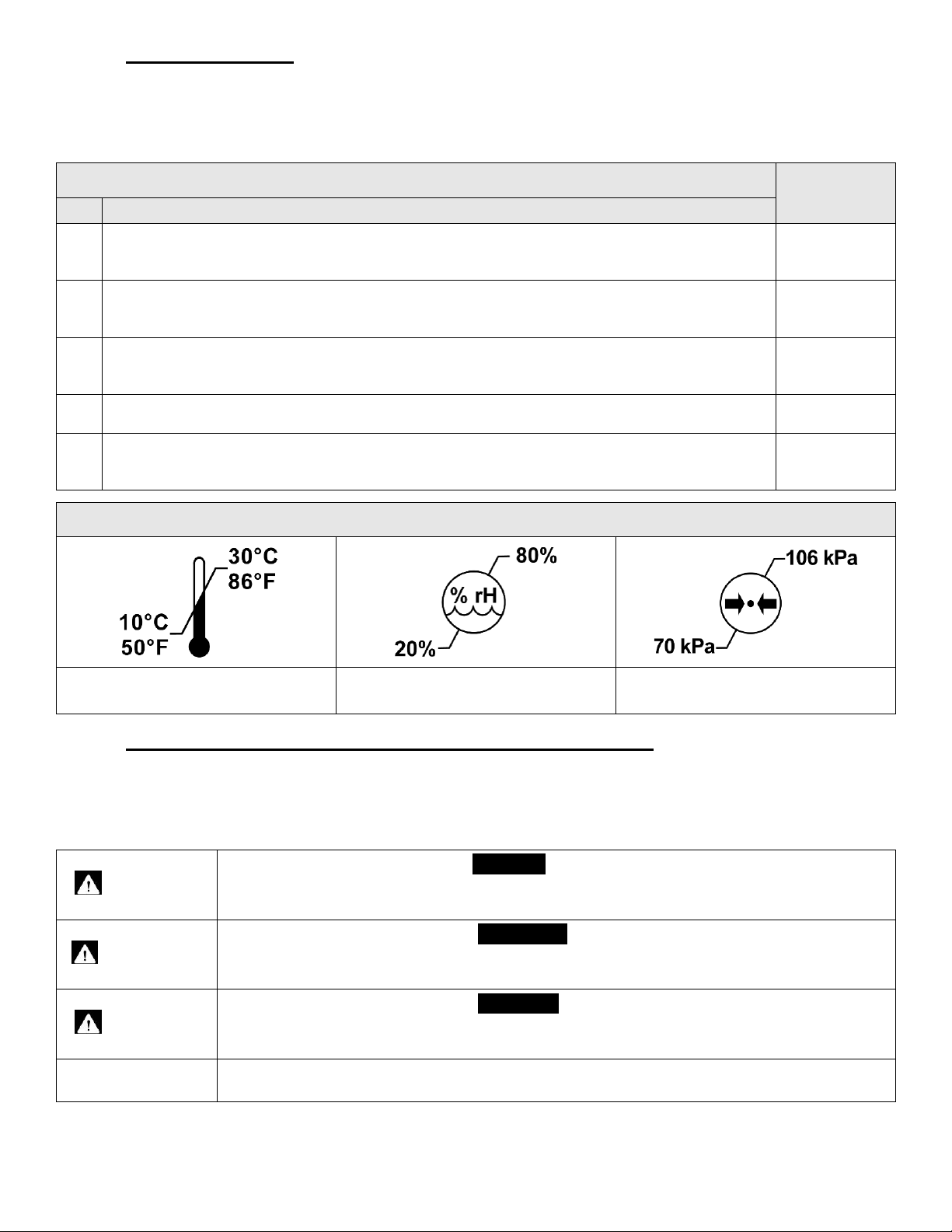
Application Environment
No.
Intensive/critical care provided in a hospital where 24 hour medical supervision and constant
1
monitoring is required and the provision of life support system/equipment used in medical
procedures is essential to maintain or improve the vital functions of the patient.
Acute care provided in a hospital or other medical facility where medical supervision and
2
monitoring is required and medical equipment used in medical procedures is often provided to
help maintain or improve the condition of the patient.
Long-term care in a medical area with medical supervision is required and monitoring is
3
provided if necessary and medical equipment used in medical procedures may be provided to
help maintain or improve the condition of the patient.
Care provided in a domestic area where medical equipment is used to alleviate or compensate
4
for an injury, disability, or disease.
Outpatient (ambulatory) care which is provided in a hospital or other medical facility, under
5
medical supervision where medical equipment is provided for the need of persons with illness,
injury, or disability for treatment, diagnosis, or monitoring.
Description
Environmental Conditions for Normal Use
Use of
Spirit™ Bed
Suitable
Suitable
Suitable
Not Suitable
Suitable
Ambient Temperature Range
1.3 Standard Conventions Used in this Manual
This manual includes information essential to the safety of the patient, staff, and equipment during the normal
operation of the Spirit™ bed. Before operating the Spirit™ bed be sure you have read and understood the
contents of this manual. It is important that you use this equipment in accordance with the procedures
outlined in this manual. As you read through this manual be alert to the four signal words.
DANGER
WARNING
CAUTION
NOTE:
1.3.1 Patient Left & Patient Right Determination
CHG Hospital Beds’ determination of the “Patient Left” and the “Patient Right” side of the bed is made from
the patient’s point of view while positioned normally on the bed facing up.
Ambient Humidity Range
(Non Condensing)
Atmospheric Pressure Range
Information appearing under the DANGER caption concerns the protection of patient,
staff and others from the immediate and imminent hazards that, if not avoided, will result
in immediate, serious personal injury or loss of life in addition to equipment damage.
Information appearing under the WARNING caption concerns the protection of
patient, staff, and others from potential hazards that can result in personal injury or
loss of life in addition to equipment damage.
Information appearing under the CAUTION caption concerns the protection of patient,
staff and others from potential hazards that can result in minor personal injury or
equipment damage.
Information appearing in a NOTE caption provides additional information which is
helpful in understanding the item being explained.
Page 11
1-70-008 – H User Manual
- Spirit Plus 5600
CHG
Hospital
Beds
Page 11
of
103
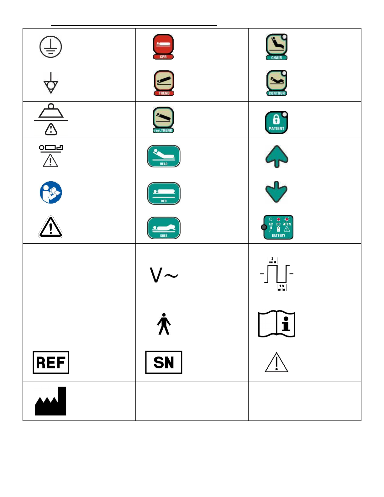
1.4 Symbols Used on the Spirit™ Bed
.
PROTECTIVE EARTH
GROUND
POTENTIAL EQUALIZATION
(EQUIPOTENTIAL POINT)
ELECTRONIC
CARDIOPULMONARY
RESUSCITATION (CPR)
FUNCTION
PRESS AND HOLD TO LOWER
ALL SECTIONS OF MATTRESS
DECK FLAT TO BED FRAME
TRENDELENBURG FUNCTION
PRESS AND HOLD TO MOVE
THE BED INTO
TRENDELENBURG POSITION
CHAIR FUNCTION
PRESS AND HOLD TO BRING
PATIENT TO SITTING
POSITION
CONTOUR FUNCTION
TOGGLE TO INITIATE
AUTOMATIC ACTION OF
KNEE-FOOT SECTION WHEN
ACTION IS INITIATED TO
HEAD SECTION OF
MATTRESS DECK
CLASS I
SAFE WORKING LOAD
THE MAXIMUM ALLOWABLE
LOAD THAT CAN BE PLACE
ON THE BED
MAXIMUM PATIENT WEIGHT
THE MAXIMUM ALLOWABLE
WEIGHT OF PATIENT THAT
CAN BE PLACE ON THE BED
READ OWNER’S MANUAL
BEFORE USE
SYMBOL TO DRAW USER
ATTENTION TO AN
IDENTIFIED DANGER,
WARNING, OR CAUTION
ELECTRICAL EQUIPMENT IN
WHICH PROTECTION
AGAINST ELECTRIC SHOCK
DOES NOT RELY ON
INSULATION
WHICH INCLUDES AN
ADDITIONAL SAFETY
PRECAUTION IN THAT
MEANS ARE PROVIDED FOR
ACCESSIBLE PARTS
METAL OR INTERNAL PARTS
OF METAL TO BE
BASIC
ONLY, BUT
OF
REVERSE TRENDELENBURG
FUNCTION
PRESS AND HOLD TO MOVE
THE BED INTO REVERSE
TRENDELENBURG POSITION
INITIATE ACTION TO HEAD
SECTION OF MATTRESS
DECK
INITIATE ACTION TO
ENTIRE MATTRESS DECK
(HI-LO)
INITIATE ACTION TO KNEEFOOT SECTION OF
MATTRESS DECK
ALTERNATING CURRENT
(AC) POWER
FUNCTION LOCK-OUT
ACTIVATE TOGGLE SWITCH
TO RESTRICT FUNCTION OF
PATIENT AND PENDANT
UP CONTROL
ELEVATES THE
CORRESPONDING SECTION
OF THE MATTRESS DECK
DOWN CONTROL
LOWERS THE
CORRESPONDING SECTION
OF THE MATTRESS DECK
POWER STATUS INDICATOR
DUTY CYCLE
2 MINUTES ON
18 MINUTES OFF
PROTECTIVELY EARTHED
IPX4
INGRESS PROTECTION CODE
(IP RATING)
CATALOGUE NUMBER
INDICATES THE
MANUFACTURER’S
CATALOGUE NUMBER SO
THAT THE MEDICAL DEVICE
CAN BE IDENTIFIED
MANUFACTURER
INDICATES THE MEDICAL
DEVICE MANUFACTURER
CONSULT INSTRUCTIONS
FOR USE
TYPE B EQUIPMENT
SERIAL NUMBER
INDICATES THE
MANUFACTURER’S SERIAL
NUMBER SO THAT A
SPECIFIC MEDICAL DEVICE
CAN BE IDENTIFIED
INDICATES THE NEED FOR
THE USER TO CONSULT THE
INSTRUCTIONS FOR USE
CAUTION
INDICATES THE NEED FOR
THE USER TO CONSULT THE
INSTRUCTIONS FOR USE
FOR IMPORTANT
INFORMATION
Page 12
1-70-008 – H User Manual
- Spirit Plus 5600
CHG
Hospital
Beds
Page 12
of
103
1.5 Technical Specifications
Certifications
Siderail Configuration Market Standard Build Date
Standard/ Long Rails US/CAN ANSI/AAMI ES 60601-1:2005/A2:2010
CAN/CSA C22.2 No. 60601-1:08
IEC 60601-1:2005/C2:2007
CAN/CSA C22.2 No. 60601-2-52:2011
IEC 60601-2-52/C1:2010
CAN/CSA C22.2 NO. 601.1-M90 (R2005)
UL 60601-1:2003
IEC 60601-1 Amd. 2 Ed 2.0 b:1995
IEC 60601-2-38 Amd 1. Ed 1.0 en:1999
CAN/CSA C22.2-No. 60601-2-38-03(R2007)
High US/CAN ANSI/AAMI ES 60601-1:2005/A2:2010
CAN/CSA C22.2 No. 60601-1:08
IEC 60601-1:2005/C2:2007
CAN/CSA C22.2 No. 60601-2-52:2011
IEC 60601-2-52/C1:2010
CAN/CSA C22.2 NO. 601.1-M90 (R2005)
UL 60601-1:2003
IEC 60601-1 Amd. 2 Ed 2.0 b:1995
IEC 60601-2-38 Amd 1. Ed 1.0 en:1999
CAN/CSA C22.2-No. 60601-2-38-03(R2007)
1/2/2013 – Present
Prior to 1/2/2013
3/19/2018 – Present
Prior to 3/19/2018
All UK ANSI/AAMI ES 60601-1:2005/A2:2010
CAN/CSA C22.2 No. 60601-1:08
IEC 60601-1:2005/C2:2007
CAN/CSA C22.2 No. 60601-2-52:2011
IEC 60601-2-52/C1:2010
CAN/CSA C22.2 NO. 601.1-M90 (R2005)
2/18/2013 – Present
Prior to 2/18/2013
UL 60601-1:2003
IEC 60601-1 Amd. 2 Ed 2.0 b:1995
IEC 60601-2-38 Amd 1. Ed 1.0 en:1999
CAN/CSA C22.2-No. 60601-2-38-03(R2007)
Articulation Range
Head Section Angle 0° to 60°
Knee Section Angle 0° to 25°
Foot Section Angle 0° to 10°
Trendelenburg 0° to MAX 14°
Reverse Trendelenburg 0° to MAX -14°
Mattress Deck Height - Lowest Elevation
10 ¾” 273 mm
Mattress Deck Height - Highest Elevation 34” 863 mm
Minimum Deck Height Required to
Accommodate Patient Lift Clearance
48” x 5” (1219 mm x 127 mm)
Electrical Specifications
Ø5” (125 mm) Casters
23 ½” 597 mm
Page 13
1-70-008 – H User Manual
- Spirit Plus 5600
CHG
Hospital
Beds
Page 13
of
103
Mode of Operation - Intermittent Operation Duty: 10% (2 Minutes ON, 18 Minutes OFF)
Mains Input Voltage 120 Volts AC
Mains Input Current 4.0 Amps
Mains Input Current (Beds with Auxiliary Mains AC Outlet) 9.0 Amps
Mains Input Current Frequency 60 Hertz
Auxiliary Mains AC Outlet - Maximum Output Power 120 Volts, 5 A
Control Locations
Footboard Staff Control Standard
Siderail Controls (Patient and Staff) Standard
Six Function Handheld Pendant Optional
Safety Features
Dual Foot Pedal – Lock & Steer Feature Standard
On-Board Battery Back-up Standard
Safety & Convenience Features on Footboard Staff Control
PRESS and Hold Electronic CPR Function Standard
Trendelenburg/ Reverse Trendelenburg Capability Standard
Chair Positioning Standard
Auto Contour Mode Standard - Toggle Button with LED
Security
Patient Lock-Outs - Bed Elevation, Head Section, and Knee/Foot Section
(Patient Controls only)
Master Lock-Out - All Patient and Staff Control Locations (including
Footboard Staff Control)
Security Lock-Out - All Patient and Staff Control Locations (including
Footboard Staff Control)
Standard – Individual Toggle Button with LED’s
Standard – Requires deactivation of Master Lock-out
to operate bed
Standard – Requires facility-set user passcode to
operate bed
Dimensions & Weight
Length (Overall Bed Length) MAX 91 ¾” MAX 2331 mm
Length - Between Head & Footboards 81” 2057 mm
Length - Mattress Deck (in 80” Mattress Position) 79¾” 2026 mm
Length - Mattress Deck (in 84” Mattress Position) 83¾” 2127 mm
Width - Between Outer Edges of Siderails 40” 1016 mm
Width - Mattress Deck 35” 889 mm
Load Capacity (Safe Working Load) 500 lbs 227 kg
Weight of Bed (Bed, Accessories, Options and Mattress) MAX 570 lbs MAX 258.5 kg
Sound Pressure Level (Measured 1m from Device)
Bed Operation - at Maximum Load (Safe Working Load) < 54 dBA
*All dimensions are nominal and have approximate manufacturing tolerances of ± ½” (12.7 mm) for length/height and ± 2° for angular dimensions.
Exception Specification of Head Section Angle to 0° to 60° +2°/-4°.
Page 14
1-70-008 – H User Manual
- Spirit Plus 5600
CHG
Hospital
Beds
Page 14
of
103
1.6 Important Electrical Precautions
AC Power Outlet Requirements
120 VAC models
Possible ELECTROCUTION Hazard
DO NOT expose the AC power supply cord or other electrical components to water.
DO NOT allow the power supply cord, AC power outlet, auxiliary AC outlet socket (if
equipped), actuators, control boxes or pendant (if equipped) to become wet or submerged
during normal bed operation or when performing cleaning.
DO NOT submerge the bed frame or electrical parts. DO NOT allow liquids to enter
electrical components. If a liquid is spilled in or around the bed, unplug the bed before
cleaning. Clean up the spill and allow the bed and/or the area around the bed to dry
thoroughly before using the controls again.
DO NOT open assemblies such as actuators, control boxes, battery, and pendant (if equipped).
These parts are not serviceable. Only service technicians, specifically trained to service CHG
Hospital Beds Spirit™ beds, should attempt to service bed and/or replace electrical components.
DO NOT use the auxiliary AC outlet socket (if equipped) if the socket receptacles appear to
be damaged and/or if the plug (of the device that you are connecting the bed to) does not
remain connected when inserted in the outlet socket receptacles.
Plug the three prong power supply cord ONLY into a properly grounded 120
VAC, 60 Hz power outlet that is rated to at least 10 A.
DANGER
DANGER
Possible EXPLOSION Hazard
DO NOT use near explosive gases. DO NOT operate this bed in the presence of a
flammable anaesthetic mixture with air or with nitrous oxide.
DO NOT use this bed in Active Treatment “Ether Environments”.
DANGER
Possible FIRE Hazard exists when connecting (plugging in) the power supply cord to an AC
power outlet if oxygen administering equipment is in use.
Use either a patient nasal mask or half-length tent, ensuring the tent NEVER extends
below the mattress deck, when administering oxygen.
DANGER
Possible FIRE Hazard exists if the pendant is not disabled when oxygen administering
equipment is in use. If bed is equipped with a pendant, disconnect the pendant from the
port at the side of the bed and insert pendant into its holster or attach pendent to bed linen
using the included linen clip when not in use.
WARNING
DO NOT operate the bed if any actuator has malfunctioned or has been damaged in any
manner.
DO NOT open assemblies such as actuators, control boxes, battery, and pendant (if
equipped). These parts are not serviceable.
Page 15
1-70-008 – H User Manual
- Spirit Plus 5600
CHG
Hospital
Beds
Page 15
of
103
WARNING
Possible ELECTRIC SHOCK Hazard exists when servicing bed and/or replacing electrical
components.
ALWAYS disconnect bed from the AC power outlet and ensure that the capacitor inside the
CB09 control box has been fully discharged before servicing bed and/or replacing any
electrical components. After the bed has been disconnected (unplugged) from the AC power
outlet, fully discharge the CB09 control box by sequentially depressing the UP and DOWN
buttons on one of the siderail controls or on the pendant (depending upon how bed is
equipped) at least 20 times.
Only service technicians, specifically trained to service CHG Hospital Beds Spirit™ beds,
should attempt to service bed and/or replace electrical components.
WARNING
All Spirit™ beds are equipped with a power supply cord storage device located at the head
end of the bed. ALWAYS keep the power supply cord clear of any moving bed parts or
mechanisms. The power supply cord should ALWAYS be stowed whenever moving,
transporting, or storing the bed.
DO NOT allow the power supply cord and/or pendant cord to become entangled around other
objects. A pinched power supply cord and/or pendant cord can become damaged and could be
dangerous. Be aware of the power supply cord and/or pendant cord location especially when
moving the bed.
DO NOT roll the bed over the power supply cord or pendant cord. DO NOT operate the
bed if the power supply cord and/or pendant cord is damaged. ALWAYS keep power supply
cord and/or pendant cord clear of moving equipment. The power supply cord is a
replaceable component by service personnel. Contact Stryker Medical Technical Service at toll
free 1-800-327-0770 (USA) or 1-800-668-8323 (Canada) for further assistance.
DO NOT position the bed so that it is difficult to disconnect the power supply cord should
the need ever arise. DO NOT use an extension cord.
WARNING
Some versions of CB10 control box are NOT interchangeable and MUST NOT be installed
on some beds. Bed may not operate as intended if incorrect version of the CB10 control box
is used.
ALWAYS confirm replacement part numbers and/or control box circuit board revisions are
the same prior to installation. Contact Stryker Medical Technical Service at toll free 1-800327-0770 (USA) or 1-800-668-8323 (Canada) for further assistance.
CAUTION
Connecting electrical equipment to auxiliary mains AC outlet effectively leads to creating a
medical equipment system and can result in a reduced level of safety. When connecting
devices, the system shall be evaluated in end use application to ensure compliance to
medical device standard 60601-1.
Page 16
1-70-008 – H User Manual
- Spirit Plus 5600
CHG
Hospital
Beds
Page 16
of
103
CAUTION
AC power outlet, or if the battery case or mounting hardware has been damaged in any way, replace the battery.
A safety feature of this product includes protection against overheating caused by excessive
or extended periods of operation. Depending on the duration, this includes multiple or
repeated adjustments or the use of multiple functions at once.
To ensure trouble free operation, ALWAYS allow a slight pause between multiple
adjustments. DO NOT exceed the maximum continuous mode of operation. Refer to page
12 for complete technical specifications.
If thermal protection activation should occur, the bed will not respond to staff commands
from any control location and the CB09 control box will need to be service and/or replaced.
WARNING
Always keep the footboard installed and locked when a patient is left unattended. When
removing the footboard, if the mating spring-return connector cover on the bed is damaged
or does not return to properly to cover the terminals, reinstall and lock the footboard then
have the bed serviced. Never touch an exposed terminal and the patient simultaneously.
1.6.1 Battery Back-up
Battery Location
All Spirit™ beds are equipped with a rechargeable, back-up battery. The battery is located under the knee
section of the mattress deck mounted to the bed frame cross member of the patient left side of the bed on
all Spirit™ beds. Refer to pages 76 for battery location.
Battery Charging and Operation Characteristics
The battery is continuously charged when connected to the CB10 control box and the bed is plugged into
an AC power outlet. When the bed is unplugged from the AC power outlet, the bed is powered by the
battery. Refer to pages 78 to ensure proper battery cable connection.
The footboard staff control on Spirit™ beds has an integrated power status indicator. When the ATTN light
is flashing, the battery requires inspection. Refer to page 55 for power status indication.
The battery is maintenance free, however battery life is not indefinite, and thus semi-annual inspection is
required to verify operation. Refer to page 66 for details. In the event the battery is deemed to be faulty, does
not hold a charge, will not operate the functions of the bed while the bed is disconnected (unplugged) from the
WARNING
After connecting a battery to the CB10 control box, the bed MUST be plugged into an AC
power outlet to energize the battery circuit and enable bed operation under battery power.
This MUST be performed regardless of the battery charge condition.
WARNING
Emergency bed functions cannot be guaranteed under abnormal operating conditions.
ALWAYS be aware of the power status indicator and take appropriate action when the
ATTN light is flashing. ALWAYS perform periodic battery inspection.
WARNING
Potential ELECTROCUTION, EXPLOSION, and/or FIRE HAZARD
These potential hazards could occur resulting in injury or loss of life in addition to
equipment damage can occur if battery is replaced with components other than those
approved for use on the Spirit™ bed by CHG Hospital Beds.
Page 17
1-70-008 – H User Manual
- Spirit Plus 5600
CHG
Hospital
Beds
Page 17
of
103
WARNING
EXPLOSION or FIRE HAZARD
DO NOT expose the battery to heat. Keep away from flames and sparks
WARNING
DO NOT connect battery to CB09 control box. The battery may overheat causing it to
swell, leak acid, and/or explode.
Connect battery only to CB10 control box. If you have to replace your CB09 control box call
Stryker Medical Technical Service to ensure that you have the correct version of this
component at toll free 1-800-327-0770 (USA) or 1-800-668-8323 (Canada).
WARNING
If a sulphuric odour (smells like a burnt match) is detected, or if any residual leakage is
found on or around the area of the battery, ALWAYS replace the battery immediately.
Battery is NOT a serviceable item. DO NOT attempt to open the battery. In the event that
the battery enclosure has been compromised, avoid contact with internal components.
Internal components are primarily lead oxide and electrolyte (sulphuric acid).
In the event a person is exposed to sulphuric acid, flush contacted area with large amounts of
water for at least 15 minutes. Remove contaminated clothing and seek medical attention if
necessary. An eye wash station and emergency shower should be readily available. If swallowed,
give large amounts of water. DO NOT induce vomiting. Seek medical attention immediately.
Lead-acid batteries can be HAZARDOUS to your health. Short-term exposure – Sulphuric
acid may cause irritation of eyes, nose and throat. Prolonged contact may cause severe
burns. Long term exposure – repeated contact causes irritation and skin burns. Repeated
exposure to mist may cause erosion of teeth, chronic eye irritation and/or chronic
inflammation of the nose, throat, and bronchial tubes.
If a sulphuric acid spill is found under the bed, dilute the spill cautiously with five to six
volumes of water and gradually neutralize with sodium bicarbonate, soda ash or lime. When
exposure level is not known, wear NIOSH approved positive pressure self-contained
breathing apparatus. Reference North American Emergency Response Guidebook #154 (or
equivalent current documentation). Be sure to wear acid resistant gloves, safety glasses,
and acid resistant clothing when cleaning a sulphuric acid spill.
CAUTION
ALWAYS unplug the bed from the AC power outlet before connecting or disconnecting the
battery.
CAUTION
ALWAYS dispose of faulty batteries or batteries that have reached the end of their service
life according to local laws and regulations. Lead acid batteries are completely recyclable.
1.6.2 Grounding
This electric bed must be grounded. In the event of a malfunction or breakdown, grounding provides a path of
least resistance for electric current, thereby reducing the risk of electric shock.
Page 18
1-70-008 – H User Manual
- Spirit Plus 5600
CHG
Hospital
Beds
Page 18
of
103
This product is equipped with a cord having an equipment-grounding conductor and a grounded plug. The
plug must be inserted into an appropriate AC power outlet that is properly installed and grounded in
accordance with all local electrical codes and ordinances.
DANGER
Improper connection of the equipment-grounding conductor can result in electrocution.
Check with a qualified electrician or service person if you are doubtful that the electrical
outlet is properly grounded.
DO NOT modify the three prong plug provided. If it will not fit into the AC power outlet,
have a proper AC power outlet installed by a qualified electrician.
Grounding reliability can only be achieved when bed is connected to an equivalent
receptacle marked “HOSPITAL ONLY” or “HOSPITAL GRADE”.
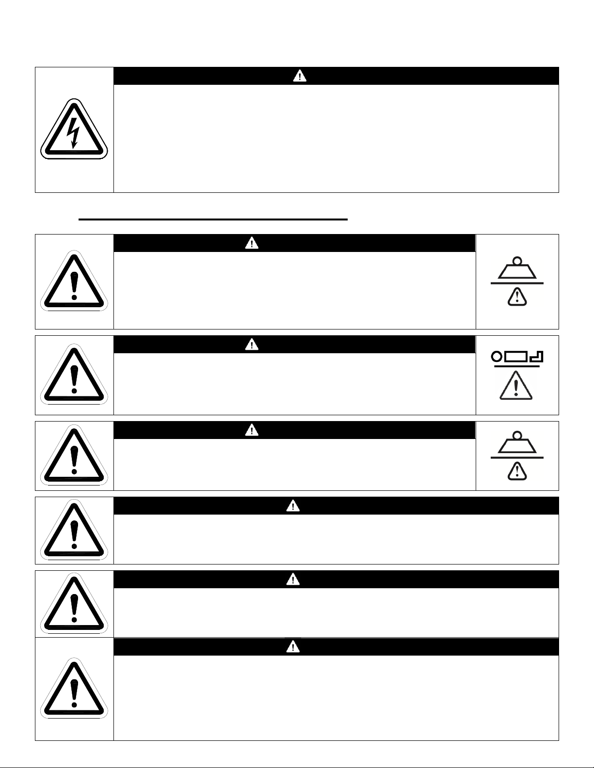
1.7 Important Mechanical Precautions
WARNING
Safe Working Load of Bed
227 kg (500 lbs)
DO NOT overload the bed. The total combined weight of patients,
visitors, mattress, additional equipment/accessories, and bedding MUST
NOT exceed 227 kg (500 lbs)
WARNING
Maximum Patient Weight
162 kg (357 lbs)
Patient weight is based on a typical bed setup (20 kg mattress + 45 kg
additional accessories)
WARNING
Safe Working Load of Siderails
80 kg (176 lbs)
DO NOT exceed a 80 kg (176 lbs) load on any siderail
WARNING
Minimum Patient Weight
22.7 kg (50 lbs)
WARNING
Minimum Patient Age
2 years old
WARNING
DO NOT use headboards or footboards from other manufacturers on any Spirit™ bed.
Spirit™ beds are specifically designed and manufactured for use in conjunction with CHG
Hospital Beds accessories. Accessories designed by other manufacturers have not been
tested by CHG Hospital Beds and are not recommended for use on Spirit™ beds.
On Spirit™ beds, ALWAYS ensure that the headboard and footboard brackets are properly
attached to the frame before use.
Page 19
1-70-008 – H User Manual
- Spirit Plus 5600
CHG
Hospital
Beds
Page 19
of
103
1.8 Mattress Specifications
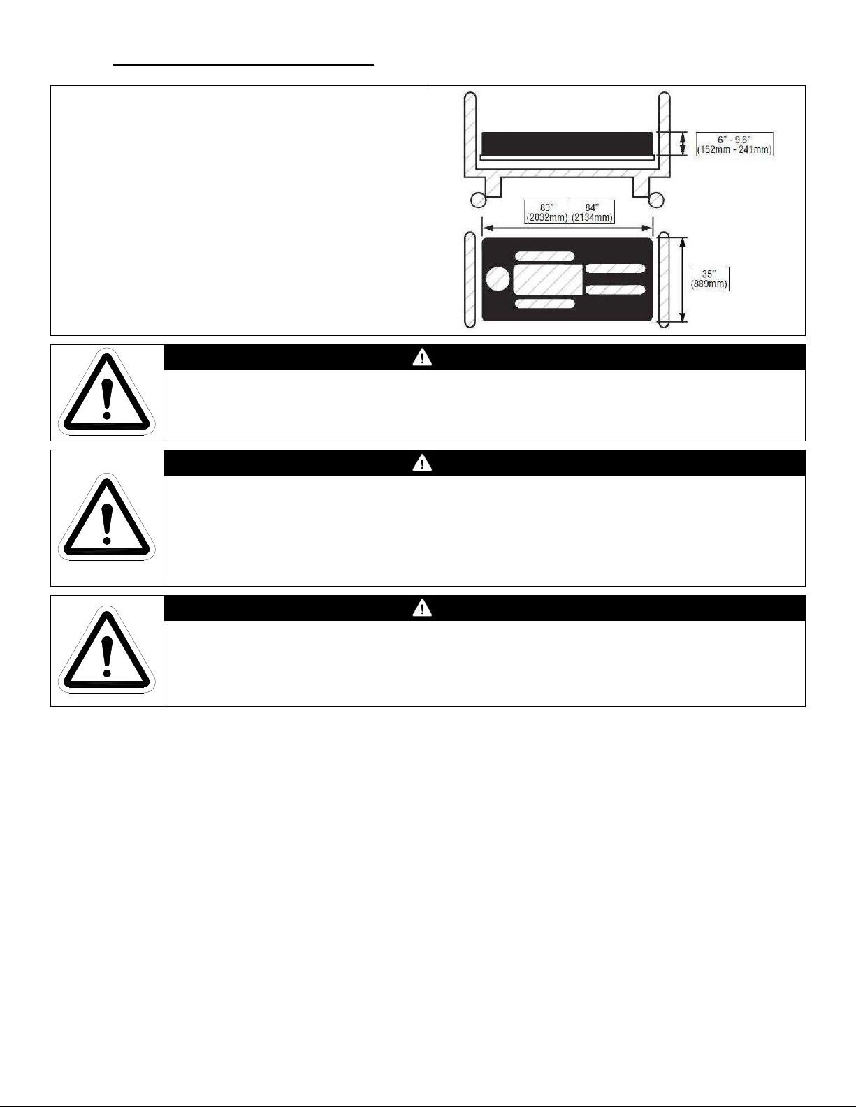
A mattress is not included with the Spirit™ bed. A
CHG Hospital Beds mattress is recommended.
Any mattress that is used on the Spirit™ bed must
suitably fit on the mattress deck and fit snugly within
the confines of the 4 corner mattress keepers having
a width of 35” (889mm).
The length and width of the mattress MUST suitably
fit on the mattress deck in either the 80” (2032 mm)
or 84” (2134 mm) configuration.
DO NOT use the bed without a mattress having a
thickness of at least 6" (152 mm) but not more than
9-1/2” (241 mm).
For mattress cleaning instructions, please see the tag on the mattress, IFU document
(2710-009-001) or contact the mattress manufacturer.
WARNING
WARNING
The mattress MUST entirely rest upon the mattress deck. The mattress MUST fit snugly
within the 4 corner mattress keepers.
Incompatible mattresses can create hazards. DO NOT use this bed without a special
mattress specifically designed to bend and conform to the shape of the bed. DO NOT use
water filled or gel filled mattress on this bed.
WARNING
Possible patient ENTRAPMENT Hazard or FALL RISK if using non-specified mattress.
Patient entrapment may result in injury or death. Use only a mattress of recommended
specifications with this bed. CHG Hospital Beds will not be responsible for any injury to patient
and/or staff and/or damage to bed that may result with use of non-specified mattress.
Page 20
1-70-008 – H User Manual
- Spirit Plus 5600
CHG
Hospital
Beds
Page 20
of
103
CHG Hospital Beds recommends that the customer perform a thorough patient assessment to
determine if the bed system and mattress selection is appropriate for the patient on the basis of
their clinical needs, fall risk, and mental capacity. CHG Hospital Beds is of the belief that to
ensure maximum patient safety, there is simply no substitute for frequent patient monitoring by
qualified healthcare practitioners. CHG Hospital Beds also recommends that the customer
conduct and document a patient entrapment risk assessment for every mattress combination
that is intended for use on the Spirit™ bed in both the flat (horizontal) and articulated positions
to identify and address any exposure to areas of potential patient entrapment and/or fall risk as
part of a comprehensive and proactive bed safety program.
A potential increase in FALL RISK may result when using the Spirit™ bed with a mattress
having a thickness greater than 6” (152mm). All patients should be monitored closely and
CHG Hospital Beds recommends that when a patient is to be left unattended the bed should
ALWAYS be lowered to the lowest position.
1.9 General Precautions
WARNING
WARNING
WARNING
Close supervision by trained healthcare practitioners is ALWAYS necessary when this
product is used by or near children and/or people with disabilities.
DO NOT let any person climb/crawl underneath the bed, between the bed legs and/or the
raised bed frame components at any time.
WARNING
DO NOT use this product or any available optional equipment without first completely
reading and understanding these instructions and any additional instructional material such
as owner’s manuals, service manuals, or instruction sheets supplied with this product or
optional equipment.
If you are unable to understand the warnings, cautions or instructions contact a healthcare
professional, your Spirit™ bed dealer, or a service technician, specifically trained to service
CHG Hospital Beds Spirit™ beds, before attempting to install and/or use this equipment,
otherwise injury to the patient and/or staff and equipment damage may occur.
WARNING
DO NOT drop the bed. DO NOT allow patients to fall onto and/or jump on the bed.
These types of activity can cause impact loads that can permanently damage the actuators
and/or other bed components resulting in an inoperable bed.
In the case of an inoperable bed due to a damaged actuator, replace the actuator
immediately. If left unattended, a damaged actuator could result in injury to the patient
and/or staff and additional equipment damage.
Page 21
1-70-008 – H User Manual
- Spirit Plus 5600
CHG
Hospital
Beds
Page 21
of
103
WARNING
Check all parts for shipping damage and test bed to confirm proper operation before
putting the bed into active service.
DO NOT use bed if any component damage is discovered or a service technician suspects
that damage has occurred. A damaged bed may expose staff and/or patients to unforeseen
safety hazards. Contact your Spirit™ bed dealer or a service technician, specifically trained
to service CHG Hospital Beds Spirit™ beds, for further instruction.
Before the bed is returned to active service after any adjustment, repair, and/or service
have been performed, ALWAYS ensure that all attaching hardware is tightened securely.
WARNING
NEVER allow patients to use trapeze or traction units as a total individual weight support.
Traction units are to be only used for immobilizing a patient in various, therapeutic, traction
set ups and/or positions that have been clinically prescribed by a trained healthcare
practitioner. Trapeze units (lifting poles) are to be only used to assist patient when
repositioning and/or transferring into or out of the bed.
WARNING
Unauthorized modifications to the equipment can result in HAZARDS. DO NOT modify the
Spirit™ bed and/or any accessories without written authorization from CHG Hospital Beds.
Use only authorized CHG Hospital Beds replacement parts and/or accessories otherwise the
warranty is void. CHG Hospital Beds will not be responsible for any injury to patient and/or
staff and/or damage to bed that may result.
WARNING
ALWAYS keep all moving parts, including the main frame of the bed, the bed legs, the
mattress deck, and all actuator shafts free of obstructions (i.e.: window sills, radiators, bed
side cabinets, under bed tables/trays, chair rails, consoles, blankets/bed linens, heating
blankets/pads, tubing, wiring, etc., and other types of products using electric cords which
may get tangled around the bed, siderails or legs) during bed operation. NEVER store
anything under the bed.
ALWAYS take the necessary precautions to avoid squeezing/shearing of routed cables
from other equipment in the moving parts of the bed.
CAUTION
DO NOT stand on the bed or concentrate weight on any particular sections of the mattress
deck. Patient body weight should be evenly distributed over the surface of the bed. DO
NOT lay, sit or lean in such a way that the patient’s entire body weight is placed only on
elevated head or foot sections of the bed. This includes situation when assisting the patient
to reposition and/or transfer into or out of the bed.
Ensure all hinges of the mattress deck sections are properly aligned before raising head or
knee sections. All four sections of the mattress deck can be detached for thorough cleaning,
sanitization, and maintenance. Refer to page 69 for instructions.
CAUTION
A patient hoist can be used with this bed however due to the ultra-low height, it has limited
underbed clearance therefore the bed must be partially raised to allow the patient hoist to
roll freely under it. Failure to raise the bed may result in damage to the bed when patient
hoists are used.
Page 22
1-70-008 – H User Manual
- Spirit Plus 5600
CHG
Hospital
Beds
Page 22
of
103
CAUTION
The Footboard is NOT designed for use as a patient therapy device. NEVER use the
Footboard as a resistance device. Any undue forces, bending or flexing of the footboard
may permanently damage the footboard and any associated electrical connections.
CAUTION
Potential PINCHING HAZARD exists between articulating deck sections and bed frame.
Moving parts and/or powered bed mechanisms can cause SERIOUS INJURY. Only
operate bed with persons clear of all mechanisms. ALWAYS keep hands clear of moving
bed parts.
Ensure that the backrest remains free from all obstructions. Obstructions could impair
normal bed operation and/or cause component damage and/or injury. If an obstruction is
detected elevate the backrest to clear obstruction before attempting to remove any
obstruction.
Page 23
1-70-008 – H User Manual
- Spirit Plus 5600
CHG
Hospital
Beds
Page 23
of
103
1.10 Standard & Optional Features
Feature Spirit Plus™
5” (125 mm) Casters Standard
4 Corner Mattress Keepers Standard
2 Patient Restraint Loops Standard
2 Drainage Bag Holders
Standard
Moulded Plastic Head/Footboards Standard
Moulded Plastic High Siderails c/w Integrated Staff, Patient Controls, and
Nurse Call Feature
Standard
Wood Laminate Head/Footboards Optional
Patient Handheld Control (Pendant) Optional
Underbed Obstruction Sensing Optional
Underbed Lighting Optional
Auxiliary AC Power Outlet Socket Optional
4” (102mm) “Easy Bed” Extension System Optional
Mental Health Package c/w Tamperproof Fasteners, Non-Removable Deck
Sections, Non-Removable Head and Footboards, Non-Removable Control Box
Optional*
Actuator Cover, and Power Supply Cord exiting from base assembly
WARNING
*A Spirit™ bed outfitted with the optional Mental Health package is a customer requested bed
configuration that is intended to perform a specialized function and has several unique differences
from regular production beds.
* A Spirit™ bed outfitted with the Mental Health package is NOT intended for normal unit use.
Page 24
1-70-008 – H User Manual
- Spirit Plus 5600
CHG
Hospital
Beds
Page 24
of
103
1.11 Siderail Assemblies
Your Spirit™ bed may be equipped with one of the following types of siderail assemblies:
Siderail Types
High Plastic Siderails
High “Filled-in” Plastic Siderails
1.12 Optional Accessories
Accessory Spirit Plus™
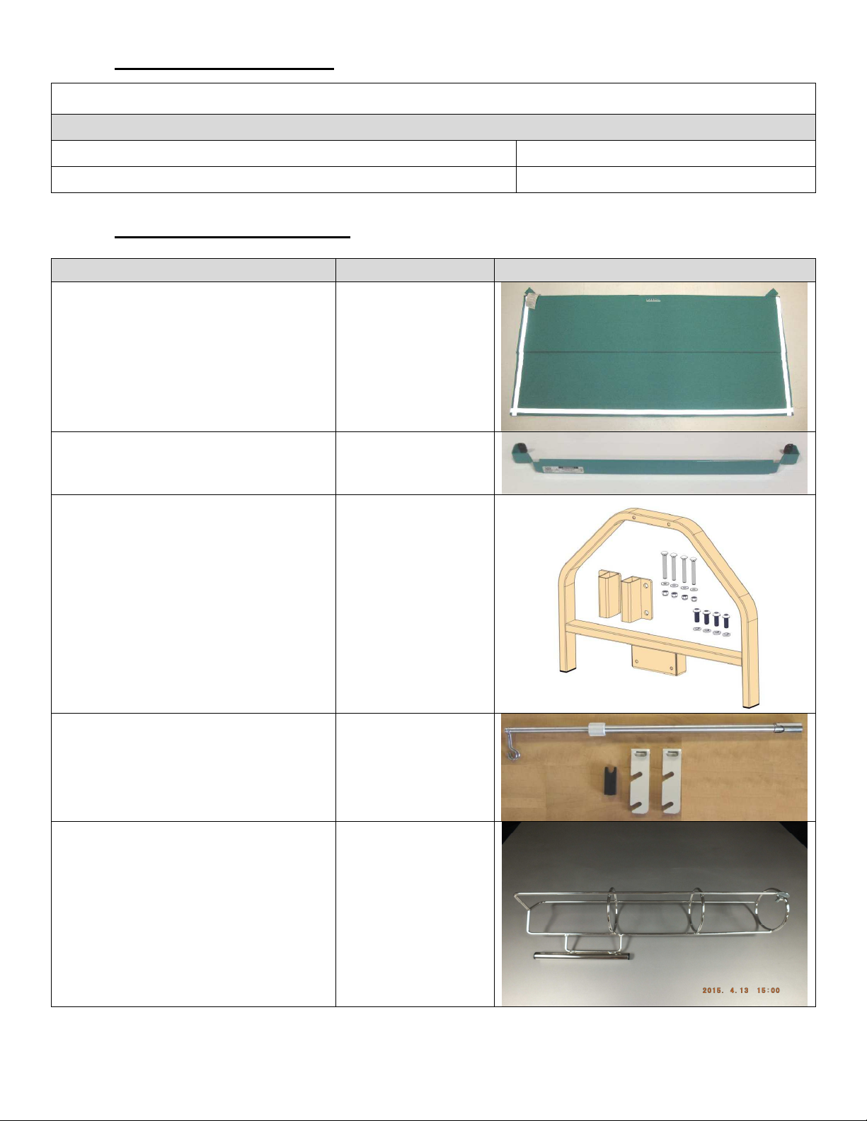
Padded Floor Mat A3321
Standard
Optional
Picture
Mattress Pump & Accessory Hanger A2601
Removable Universal Trapeze Adapter A2404
Collapsible IV Pole and Brackets A2355
Vertical Oxygen Tank Holder A2210
**Accessory, once installed onto and/or fastened to bed is no longer considered detachable
Page 25
1-70-008 – H User Manual
- Spirit Plus 5600
CHG
Hospital
Beds
Page 25
of
103
1.13 Detachable Components
NEVER attempt to install a headboard at the foot end of the bed and vice versa. ALWAYS
ensure that the footboard is installed in the proper orientation. The footboard staff control
MUST ALWAYS face away from the patient. NEVER drop a footboard. A damaged
footboard staff control and/or footboard staff control connector could result in the inability
to operate the bed from this control point.
On Spirit™ beds configured with wood laminate head/footboards, the footboard cable
MUST be disconnected before the footboard can be removed from the bed. Failure to
disconnect the footboard cable prior to footboard removal may result in component damage
and/or the inability to operate the bed from the footboard staff control.
CAUTION
CAUTION
1.14 Applied Parts
CHG Hospital Beds considers that the following are the Applied Parts of the Spirit™ bed: any head/footboard
assemblies, head/footboard bracket assemblies, any siderail assemblies, all sections of the mattress support
platform (deck) and associated mattress keepers, any CHG Hospital Beds’ supplied pendant (if equipped),
any CHG Hospital Beds supplied (Prevention Surface) mattress (if equipped).
1.15 Storage & Transport
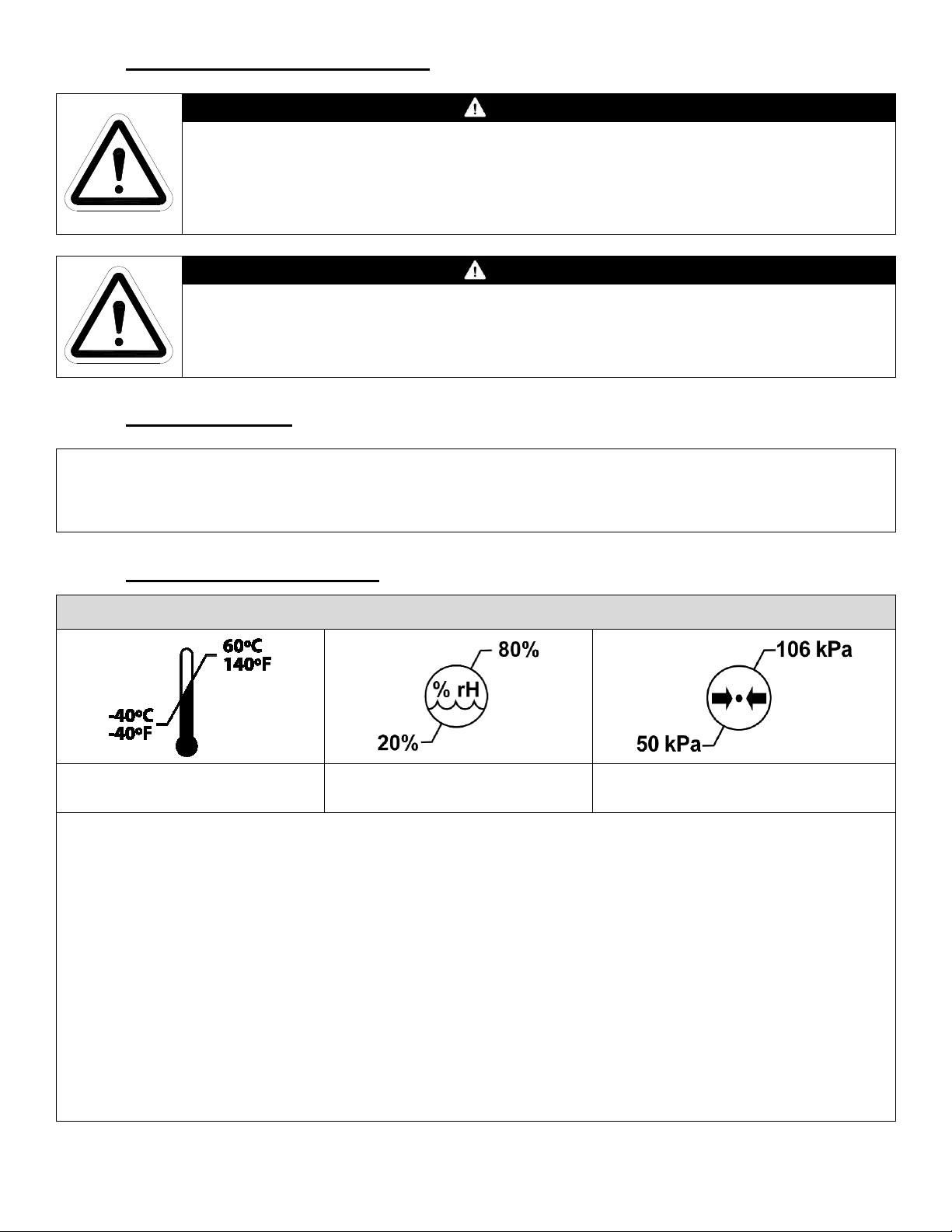
Environmental Conditions for Storage and Transport
Ambient Temperature Range
Ambient Humidity Range
(Non Condensing)
During extended periods of disconnect from an AC power outlet, the battery is susceptible to permanent
damage caused by being deep discharged. All Spirit™ beds are equipped with a disconnect feature which
automatically disengages the battery from the battery circuit to prevent damage from being deep discharged.
There is no need to disconnect the battery when a Spirit™ bed is going to be put into storage, however, the
CB10 control box will continue to draw power until the battery voltage has hit the 18V threshold which triggers
the automatic circuit disconnection.
Atmospheric Pressure Range
IMPORTANT: A battery voltage of 18V is insufficient to operate the bed. Reconnect bed to an AC power
outlet as soon as possible to and allow battery to charge for a period of 24hr to ensure that the bed will
reliably operate on battery power when needed.
IMPORTANT: To conserve battery life during storage and transport, disconnect the battery from the CB10
control box. On Spirit™ beds equipped with CB10 control boxes, even if a battery was fully charged when it
was unplugged from the control box, the bed will not operate on battery power if the battery is simply
reconnected to the control box. The bed must be connected to an AC power outlet to energize the battery
circuit. This will enable bed operation on battery power.
Page 26
1-70-008 – H User Manual
- Spirit Plus 5600
CHG
Hospital
Beds
Page 26
of
103
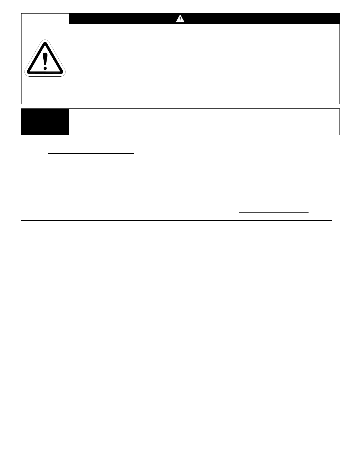
CAUTION
DO NOT re-use any original packaging material to transport the bed.
ALWAYS transport the bed by rolling the bed on its casters.
ALWAYS ensure the Central “Lock & Steer” system is in the “BRAKE” position before
attempting to lift/lower bed. ALWAYS ensure that the Central “Lock & Steer” system is in
the “BRAKE” position after the bed is loaded onto transportation vehicle. Use additional
strapping or tie downs as necessary to ensure the bed does not move while in transport.
DO NOT use the siderails as a means of mechanically restraining the bed during
transportation and/or storage. DO NOT use the siderails as lifting points for the bed during
transportation and/or storage.
CHG Hospital Beds recommends that following any storage and/or transportation in
NOTE:
extreme temperature conditions that you allow the bed to acclimatize for a period of at
least 24 hours before the bed is operated/powered up and/or put into service.
1.16 Ultra-Low Feature
The Spirit™ product line is a family of ultra-low beds, designed to reduce patient injury due to falls out of bed.
Therefore, in an effort to reduce patient injury, CHG Hospital Beds recommends that you ALWAYS lower the
bed completely to the lowest position before leaving a patient unattended.
Regardless of the purpose for which bed rails are being used or considered, a decision to utilize or remove
those in current use should occur within the framework of an individual patient assessment. For Further
information refer to the FDA’s website at http:/www.fda.gov/cdrh/beds/ for Clinical Guidance for the
Assessment and Implementation of Bed Rails in Hospital, Long Term Care Facilities, and Home Care Settings.
Available floor mats and nurse call can be used in conjunction with the low bed based on the patient
assessment and care plan.
Page 27

1-70-008 – H User Manual
- Spirit Plus 5600
CHG
Hospital
Beds
Page 27
of
103
Section 2:
Set-Up Instructions
Page 28
1-70-008 – H User Manual
- Spirit Plus 5600
CHG
Hospital
Beds
Page 28
of
103
2.1 Unpacking Instructions
Drill/Driver
¾” Socket
#3 Phillips Bit
5/16” Socket
Follow these instructions to unpack and set up the bed. These instructions are for reference only, as your
shipping materials may vary.
CAUTION
To Prevent permanent damage to this unit, please let the unit reach room temperature
prior to use (18.3 to 26.77°C or 65 to 80°F)
CAUTION
Equipment DAMAGE may result from improper plastic tie wrap removal.
DO NOT cut any trimmed plastic tie wraps. Trimmed plastic tie wraps are permanent
features on the Spirit™ bed.
WARNING
BED IS TOP HEAVY!!!
Bed may TIP OVER when positioned upright during storage and/or
transport
WARNING
BED IS HEAVY!!!
Improper handling may result in serious injury to personnel and/or
damage to bed.
Use proper lifting techniques when lifting or lowering bed.
DO NOT attempt to lower bed without assistance.
Required Tools
Knife Side Cutters
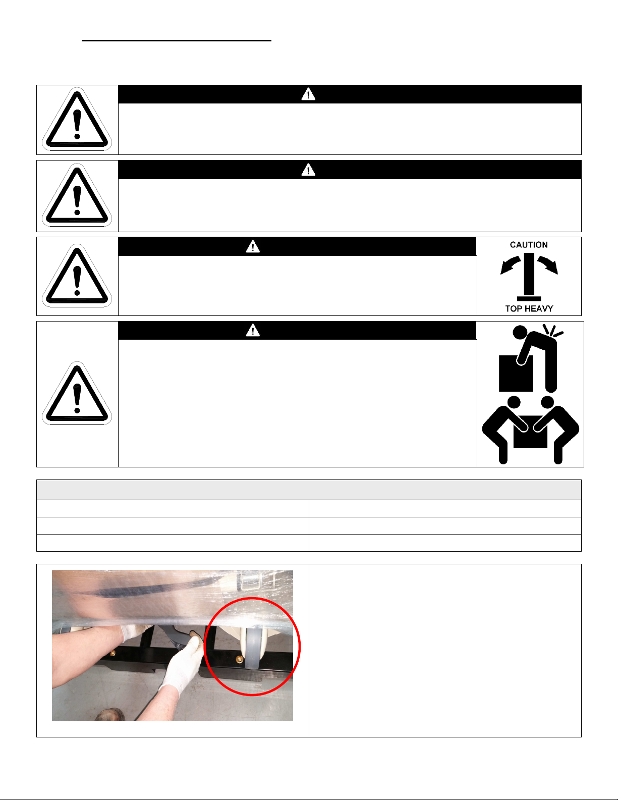
Ensure the brake is engaged before attempting to
lower/lift the bed. Attempt to rotate a caster to
confirm that the brake has been engaged.
Ensure correct orientation of the casters once locked.
Casters should be oriented lengthwise with the bed
(circled).
*IMPORTANT: Prior to lowering the bed, ensure
that you have adequate room. At least 8 feet is
required to lower the bed from the upright
transportation/storage position.
Page 29
1-70-008 – H User Manual
- Spirit Plus 5600
CHG
Hospital
Beds
Page 29
of
103
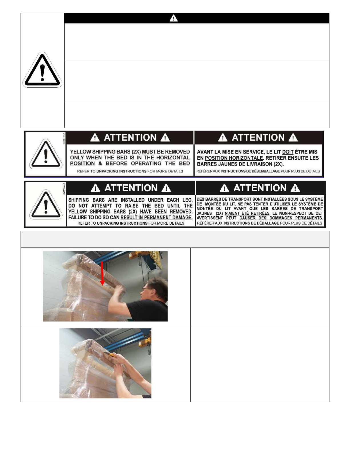
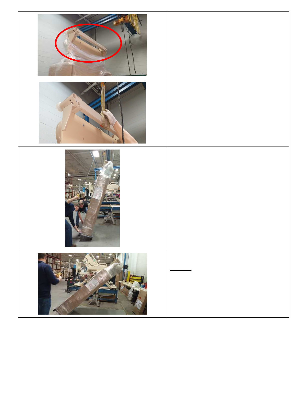
MANUAL LOWERING OF BEDS:
At this point, maintain your grip, lock your arms, and
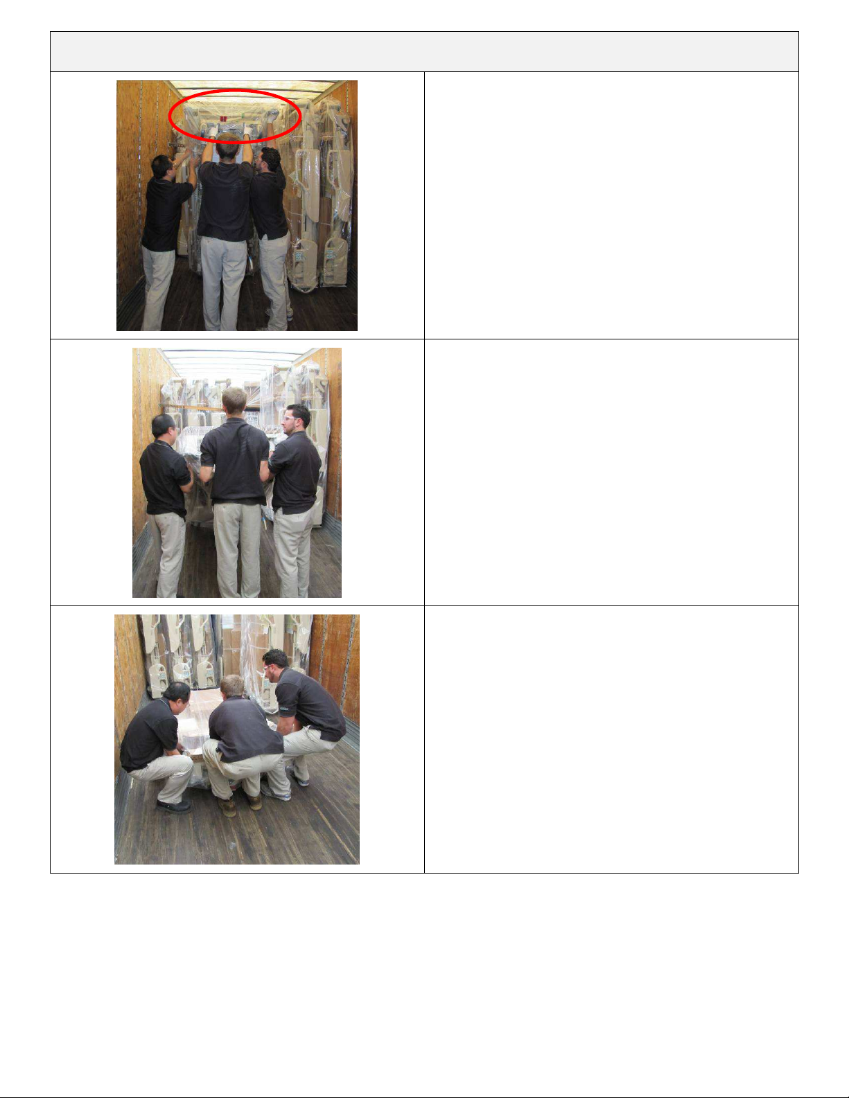
The Spirit™ bed is typically shipped standing on-end,
use sufficient manpower to carefully lower it to the
floor.
Firmly grasp the bed frame at the foot end of the bed
(circled). Begin lowering the bed by gently pulling the
bed from the upright position and slowing walking
backwards.
Continue lowering the bed by slowing walking
backwards. It may be necessary to reposition your
grip to allow further lowering of the bed.
*IMPORTANT: Communicate with the other people
before adjusting your grip!
lower the bed to the floor by bending your knees.
*IMPORTANT:
Do not drop bed!
Page 30
1-70-008 – H User Manual
- Spirit Plus 5600
CHG
Hospital
Beds
Page 30
of
103
lower/lift
WARNING
DO NOT drop the bed when lowering during storage and/or transport. If the bed is dropped, permanent
damage to bed components may occur. This may result in an inoperable bed or a bed with severely
impaired operation.
DO NOT use a bed that has been dropped. Non obvious damage may have occurred that may expose staff
and/or patients to unforeseen safety hazards.
The Central “Lock & Steer” system MUST be in the “BRAKE” position prior to attempting to lower/lift the
bed. If the brake has not been engaged, the bed may roll away from personnel while attempting to
the bed. This may result in a very rapid descent and/or unexpected bed motion that may cause severe
INJURY to personnel lowering/lifting bed and/or permanent DAMAGE to bed.
Before lowering/lifting bed, ALWAYS attempt to roll/rotate a caster to confirm that the brake is engaged.
DO NOT use the siderails as lifting/lowering points for the bed.
DO NOT use the siderails as a means of mechanically restraining the bed during transportation and/or
storage.
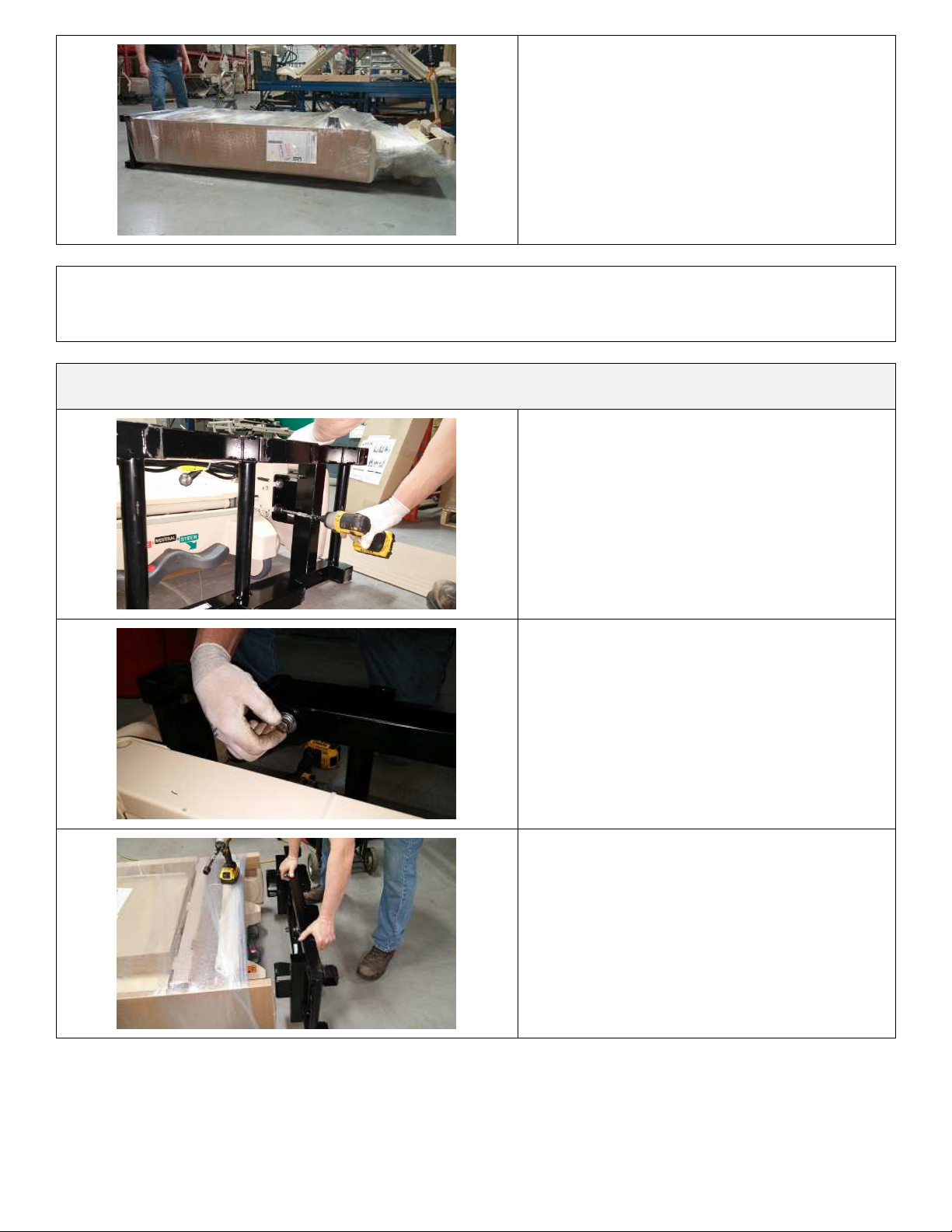
CRANE-ASSISTED LOWERING OF BEDS:
While the bed is upright, pull the shrink wrap
down, away from the footboard bracket.
Using a knife, cut the plastic bag covering the
footboard bracket.
*IMPORTANT: Ensure plastic bag is cut along
the cardboard protector to prevent damage to
the bed.
Page 31
1-70-008 – H User Manual
- Spirit Plus 5600
CHG
Hospital
Beds
Page 31
of
103
Ensure the footboard bracket is fully clear to
allow the crane device to properly attach to the
footboard bracket.
If using a crane device, ensure the strap is
secured in the centre of the footboard
bracket.
*IMPORTANT: Ensure the crane strap is not
placed over the blindmate connection.
Begin to lower the bed using the crane device.
Monitor the head end of the bed (shipping
stand), to ensure there is no “kick out” of the
bed.
Continue to lower the bed.
DO NOT drop the bed when lowering
during storage and/or transport. If the
bed is dropped, permanent damage to
bed components may occur. This may
result in an inoperable bed or a bed with
severely impaired operation.
Page 32
1-70-008 – H User Manual
- Spirit Plus 5600
CHG
Hospital
Beds
Page 32
of
103
Ensure bed is fully lowered and placed flat on
Once the 4 bolts are removed, insert them into
the ground.
IMPORTANT:
Ensure User Manual is removed from the bed. Keep User Manual with the bed.
Read all warnings documented in the User Manual.
UNPACKING FOR ALL BEDS
Using a ¾” Socket with a drill/driver, remove
the four bolts securing the ship stand to the
bed.
the four designated PEM nuts on the ship
stand.
Remove the ship stand from the head end of
the bed.
Page 33
1-70-008 – H User Manual
- Spirit Plus 5600
CHG
Hospital
Beds
Page 33
of
103
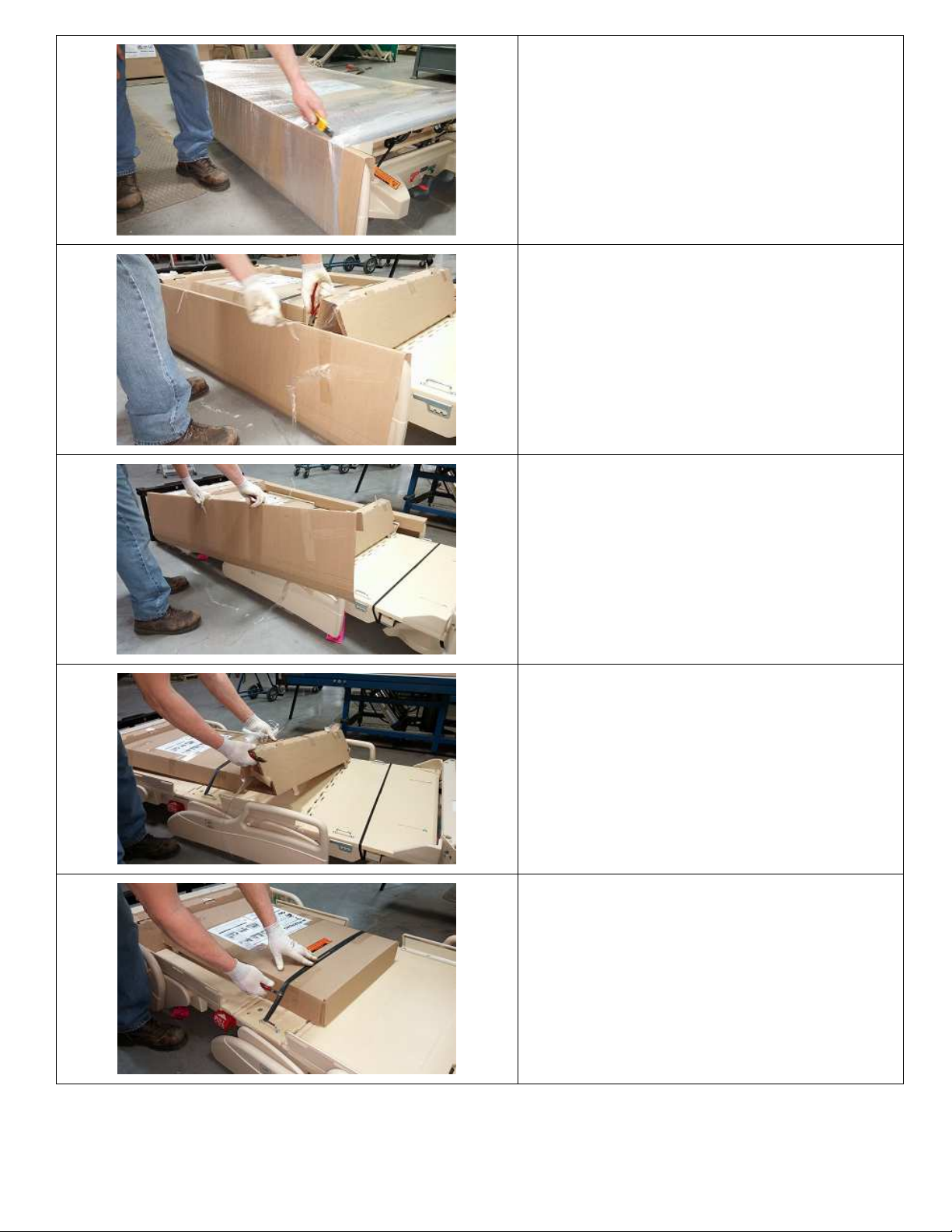
Using a knife, cut the shrink wrap around the
Using side cutters, cut the banding strap which
bed.
Start at the cardboard covering for the rails.
*IMPORTANT: Use light pressure to ensure
the knife does not go through the cardboard,
resulting in damage to the rails.
Using side cutters, cut the cable ties, which
secure the cardboard rail covers.
Remove the cardboard rail covers.
Remove the seat deck cardboard filler.
secures the head/footboard box to the top of
the deck.
Page 34
1-70-008 – H User Manual
- Spirit Plus 5600
CHG
Hospital
Beds
Page 34
of
103
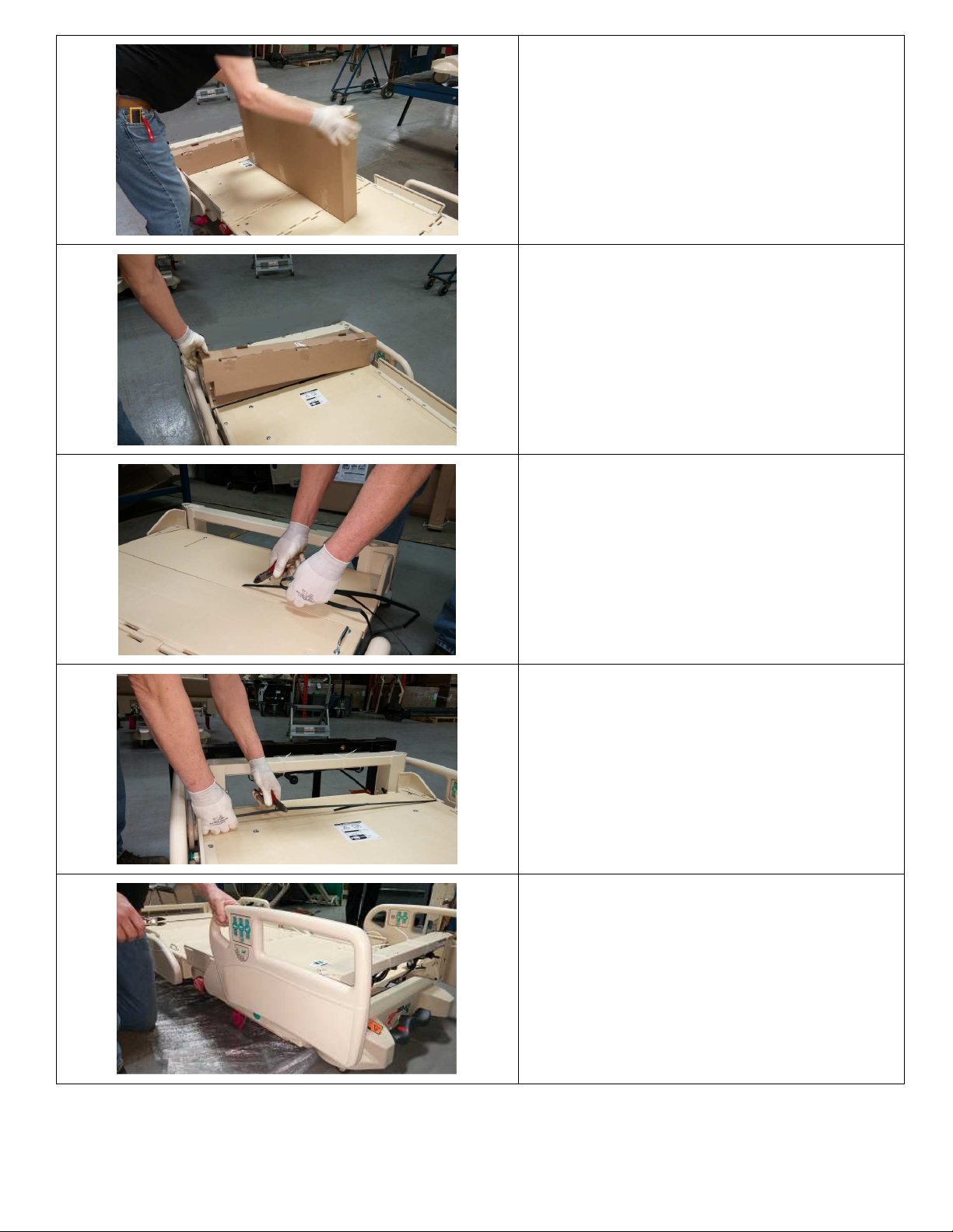
Remove the head/footboard box from the top of
Using side cutters, cut the banding
strap at the
the deck.
Remove the head end cardboard filler.
Using side cutters, cut the banding strap at the
FOOT END of the bed which secures the deck to
the frame.
HEAD END of the bed which secures the deck to
the frame.
Manually
lift the HEAD RAILS.
Page 35
1-70-008 – H User Manual
- Spirit Plus 5600
CHG
Hospital
Beds
Page 35
of
103
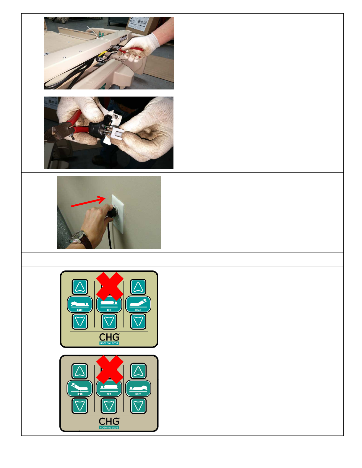
Using side cutters, cut the cable ties which
Connect bed to mains AC power.
secure the power cord to the headboard
bracket.
Remove the plug cover from the power cord.
The bed is now ready to plug in.
!! IMPORTANT !!
DO NOT PRESS BED UP
UNTIL SHIPPING CLAMP
BARS HAVE BEEN REMOVED!
The bed is still equipped with the yellow
shipping leg clamp bars.
Raising the bed with the shipping clamps
installed can cause irreparable damage to the
bed and/or components, resulting in an
inoperable bed or a bed with severely impaired
operation.
Page 36
1-70-008 – H User Manual
- Spirit Plus 5600
CHG
Hospital
Beds
Page 36
of
103
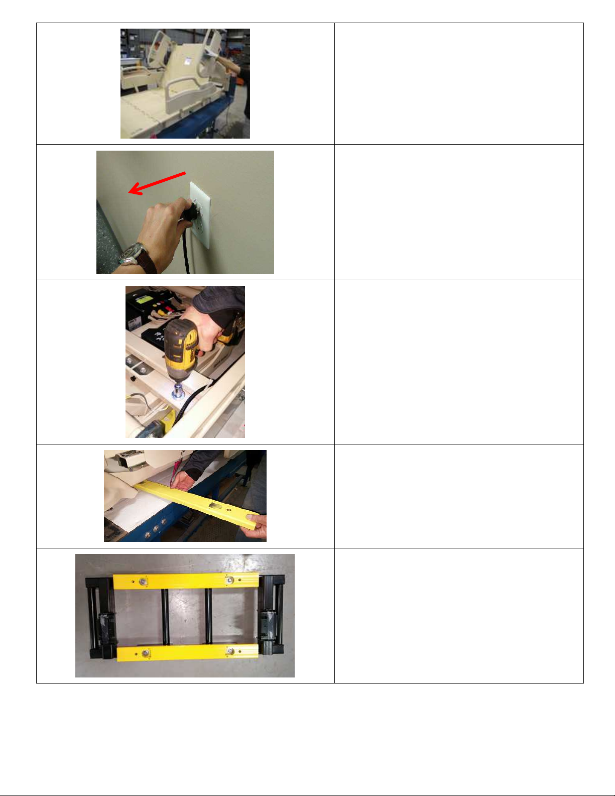
Fully raise Head deck by pressing the HEAD UP
Disconnect bed from mains AC power.
button on the side rail controls.
Locate 4 x Bolts securing the Shipping Leg
Clamp to the frame.
There are 2 bolts located at each end of the
bed.
Using a 5/16” socket with drill/driver remove the
bolts securing the shipping clamp to the cross
member of the bed frame
Remove Shipping leg clamp from underneath
the bed.
Place with previously removed shipping stand.
Re-use the four small bolts to secure the two
yellow shipping clamps to the shipping stand, as
shown. This assembly (shown) is to be returned
to Stryker Medical London.
Page 37
1-70-008 – H User Manual
- Spirit Plus 5600
CHG
Hospital
Beds
Page 37
of
103
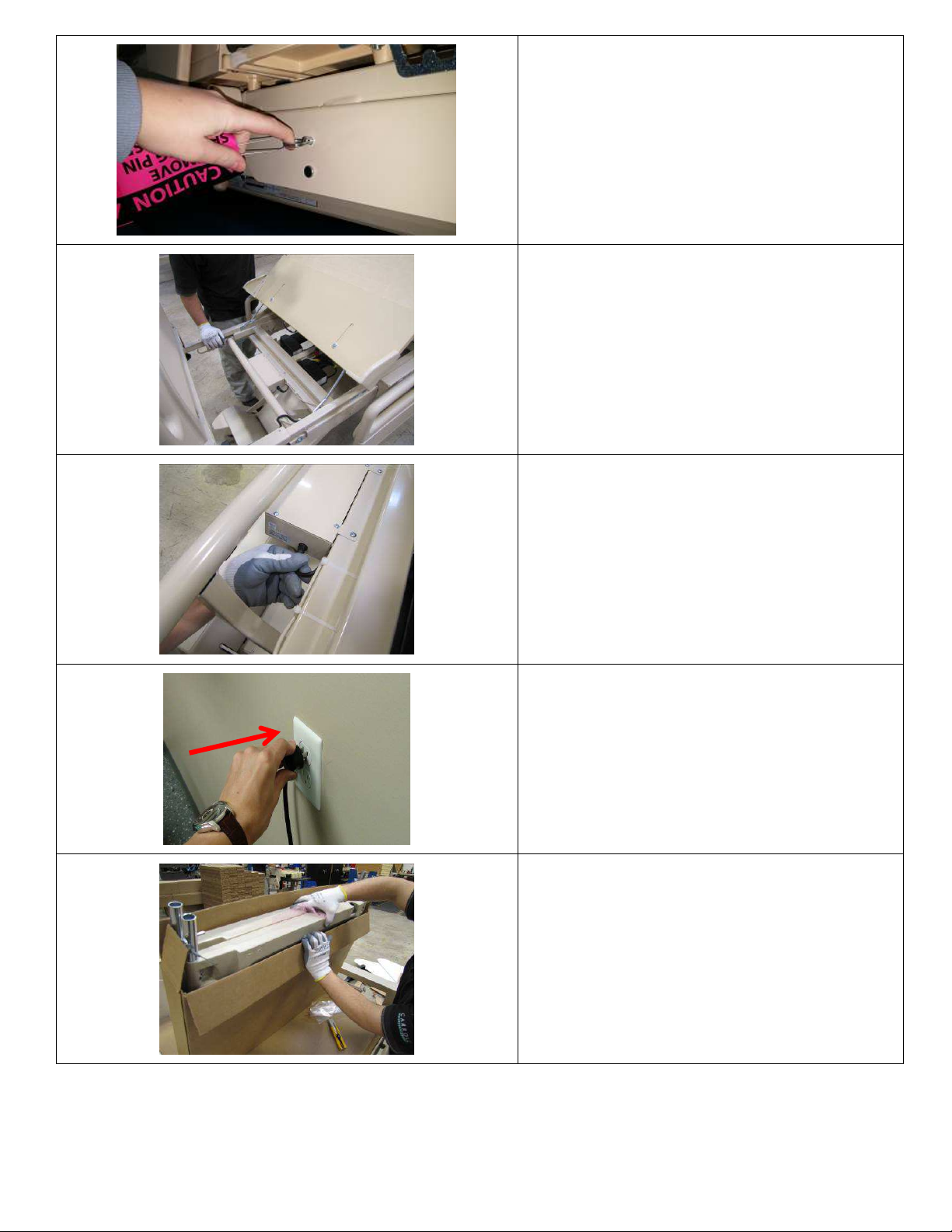
Remove shipping pins from the four saddle
brackets on the bed. These pins secure the load
cells.
Manually lift the knee/foot decks to gain access
to the CBXX enclosure.
Connect the battery cable to the side DC jack of
the CBXX enclosure.
IMPORTANT: This will ensure the on-board
battery remains fully charged and will be ready
for use in the event that mains AC power is
disrupted.
Return mains AC power to the bed.
Unpack the headboard and footboard from their
box.
Unpack the four black plastic clips and any
mental health hardware (if applicable).
Page 38
1-70-008 – H User Manual
- Spirit Plus 5600
CHG
Hospital
Beds
Page 38
of
103
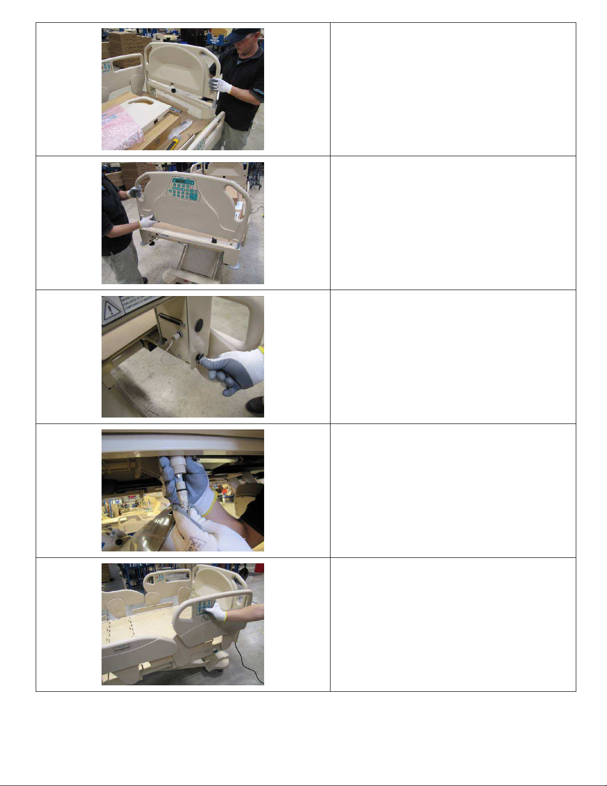
Place the headboard into the headboard bracket
The bed
MUST
be initialized before it can be
assembly.
Place the footboard into the footboard bracket
assembly.
Electrical connection is made when the
footboard is inserted into the bracket assembly;
footboard becomes inactive when removed.
Install 4 black plastic barbed clips (from the
head/footboard box) into the four holes on the
headboard bracket, where the shipping stand
was previously attached.
If your bed is equipped with the optional
pendant, unscrew cap on desired pendant port
(either side of the bed). Align arrows and insert
pendant connector into pendant port. Slide up
and screw on threaded retaining collar attached
to the pendant.
used.
Using the BED DOWN button, fully lower the
bed using any control location (Footboard staff
control, siderail control, pendant, etc.)
IMPORTANT: Ensure that the power cord is
free of moving bed parts
Page 39
1-70-008 – H User Manual
- Spirit Plus 5600
CHG
Hospital
Beds
Page 39
of
103
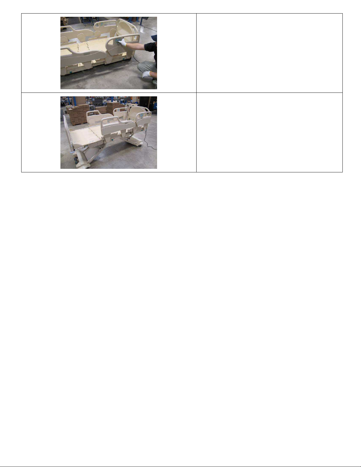
Once the bed is fully lowered and all bed motion
has automatically stopped, CONTINUE to hold
the BED DOWN button until the audible “chirp”
sounds. Continue to hold BED DOWN for an
additional 10-15 seconds to complete the Soft
Reset.
This process will synchronize the Hi-Lo actuators
so that the bed will perform properly.
Your new Spirit™ bed is now ready for use.
Page 40

1-70-008 – H User Manual
- Spirit Plus 5600
CHG
Hospital
Beds
Page 40
of
103
Section 3:
Bed Operation
Page 41
1-70-008 – H User Manual
- Spirit Plus 5600
CHG
Hospital
Beds
Page 41
of
103
3.1 Central “Lock & Steer” System
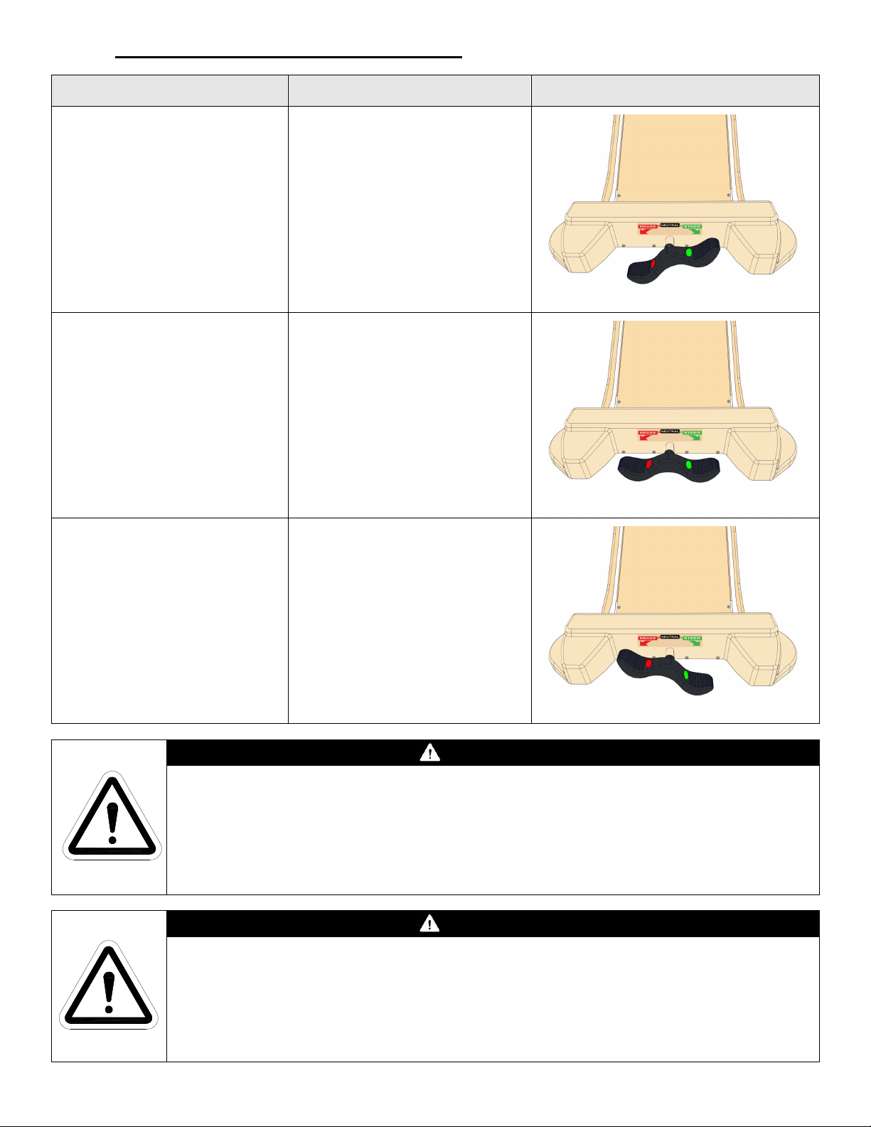
Mode Caster Functionality Pedal Position
“BRAKE”
Mode used to stabilize the bed
from shifting.
This mode prevents the bed
from moving forwards,
backwards or sideways.
“NEUTRAL”
Mode used only to manoeuvre
the bed in a tight area.
This mode allows the bed to
move forwards, backwards or
sideways.
“STEER”
Mode used when attempting to
steer the bed in a desired
direction.
All caster wheels can still
rotate, enabling the bed to
move forwards or backwards.
Casters DO NOT swivel or roll
All casters swivel and roll
Head end casters swivel
Foot end casters DO NOT swivel
All casters roll
WARNING
Unintended bed movement may occur if bed is left in either of the two mobilized positions;
“STEER” or “NEUTRAL”.
NEVER leave the bed unattended in either the “STEER” or “NEUTRAL” positions.
ALWAYS engage the “BRAKE” when leaving a patient unattended.
DO NOT attempt to move the bed until the “BRAKE” has been released.
WARNING
When transferring into or out of the bed, ALWAYS ensure that the “BRAKE” is engaged
(casters are locked). Inspect the caster locks for correct locking action before actual use.
Even with the “BRAKE” properly engaged (caster properly locked), some flooring surfaces
such as tile or wood will allow the bed to move under some conditions. Bed use on surfaces
such as these MUST be evaluated by the healthcare facility and deemed safe before the
bed is put into active service.
Page 42
1-70-008 – H User Manual
- Spirit Plus 5600
CHG
Hospital
Beds
Page 42
of
103
3.1.1 Bed Mobilization & Stabilization
Bed Mobilization
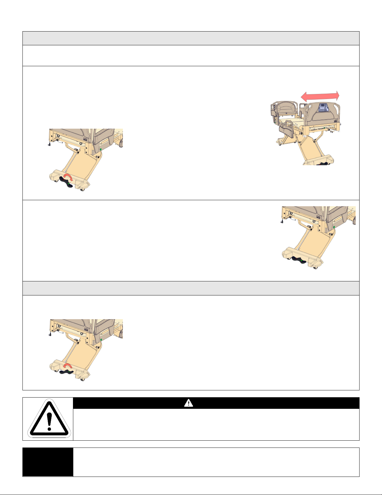
The bed is mobile when the Central “Lock & Steer” pedal is in either the “NEUTRAL” or “STEER” position.
Use either of these two pedal positions depending on the situation, when bed mobility is needed.
Enable “Steer”
Fully depress the right side of the Central
“Lock & Steer” pedal at either end of the
bed. Pedal actuation mechanism should
make an audible engagement when
switching between modes.
IMPORTANT: Depending
upon the orientation of the
castors, it may be necessary
to roll the bed sideways, in a
back and forth motion, at the
foot end of the bed until the
steering casters become
engaged in the “STEER”
mode.
Side-to-Side Motion
Put the bed into “Neutral”
Depress or lift the Central “Lock & Steer” pedal with your foot until the
pedal is level. Pedal actuation mechanism should make an audible
engagement when switching between modes.
The bed can be put in “NEUTRAL” regardless of caster orientation.
Bed Stabilization
The bed is stable when the Central “Lock & Steer” pedal is in the “BRAKE” position. Use this pedal position
whenever the bed is left unattended or when the bed needs to remain stable.
Apply the “BRAKE”
Fully depress the left side of the Central “Lock & Steer” pedal
at either end of the bed. Pedal actuation mechanism should
make an audible engagement when switching between modes.
The “BRAKE” can be applied regardless of caster orientation.
NOTE:
WARNING
DO NOT to move the bed until the siderail assemblies have been fully raised/closed and
locked/latched in the UP position Refer to page 56 for siderail operation instructions.
When the “NEUTRAL” mode is activated properly, the bed should move freely without any
unusual noises. If any clicking noises are heard when in the “NEUTRAL” position, stop and
ensure that the Central “Lock & Steer” pedal is level. Adjust, if necessary.
Page 43
1-70-008 – H User Manual
- Spirit Plus 5600
CHG
Hospital
Beds
Page 43
of
103
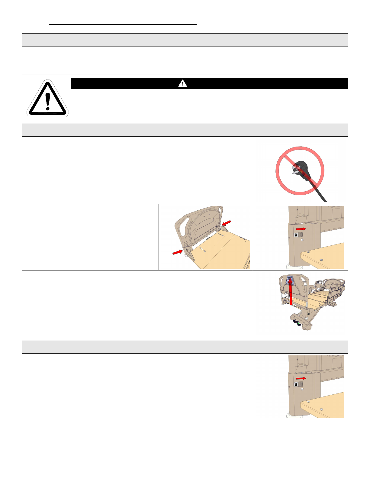
3.2 Footboard Locking Mechanism
Footboard Retention
All Spirit™ beds are configured with a footboard locking mechanism (excluding mental health applications).
Certain circumstances may require the removal of the footboard (cleaning/maintenance/storage). This
mechanism allows for easy removal of the footboard for these purposes.
WARNING
ALWAYS ensure the footboard is fully seated and the mechanism is fully engaged during
patient use. Failure to secure the footboard may result in decreased bed performance
and/or patient injury.
Footboard Removal
Disconnect the bed from Mains AC power before initiating the removal of the
footboard.
Locate the locking mechanism on the inboard
side of the footboard bracket denoted by a
“lock” symbol.
Slide the locking tab towards the inside of the
bed frame away from the “lock” symbol.
Repeat for second lock mechanism (opposite
side).
Firmly grasp footboard handle holds, and pull up on footboard to remove from the
footboard bracket.
Footboard Installation
Locate the locking mechanism on the inboard side of the footboard bracket
denoted by a “lock” symbol.
Ensure the locking tabs are towards the inside of the bed frame away from the
“lock” symbol.
Repeat for second lock mechanism (opposite side).
Page 44
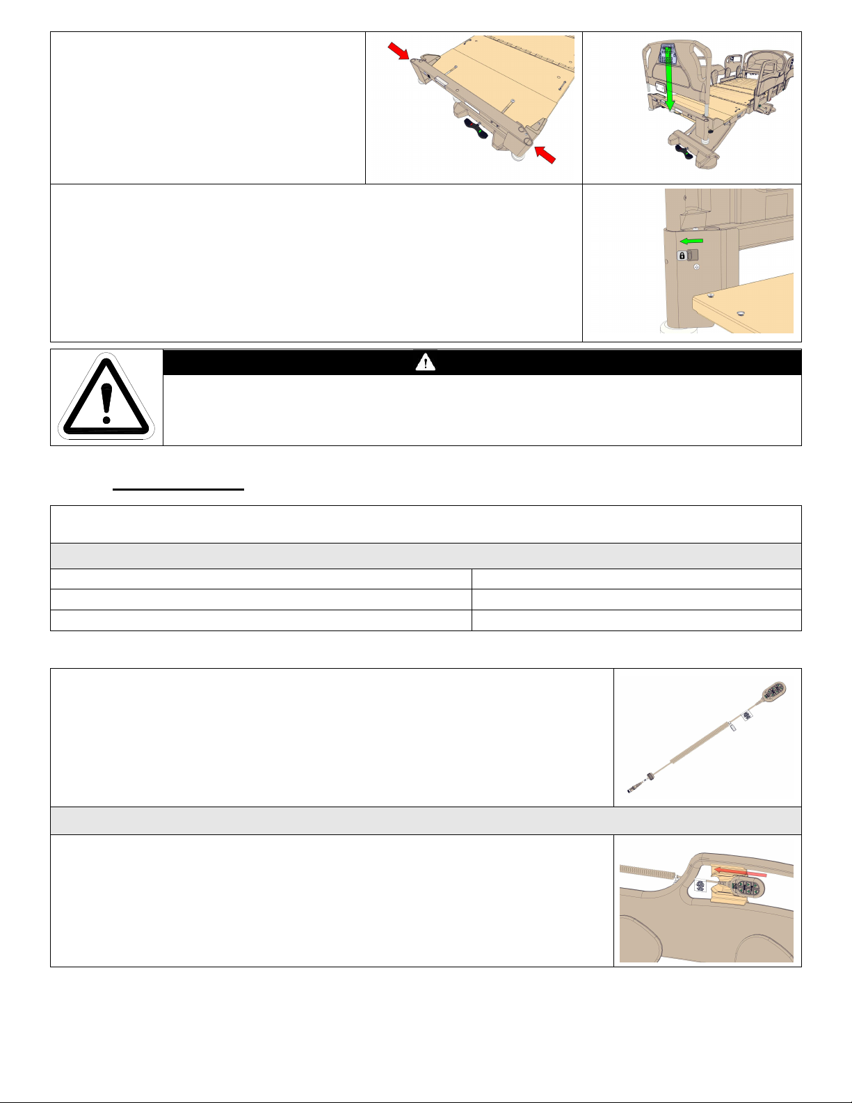
1-70-008 – H User Manual
- Spirit Plus 5600
CHG
Hospital
Beds
Page 44
of
103
Firmly grasp footboard handle holds, and align
Depending on the
Spirit™
bed you purchased, you will have two or th
ree locations for controlling bed
footboard posts with footboard bracket receiving
tubes.
Install footboard into receiving tubes.
Slide the locking tab towards the outside of the bed frame towards the “lock”
symbol.
Locking tab should slide easily while engaging footboard posts.
Repeat for second lock mechanism (opposite side).
Gently “tug” upwards on footboard to ensure footboard is properly seated and
secured by the locking mechanism – footboard should experience very little
movement.
CAUTION
DO NOT force footboard into place, footboard should easily engage and seat in receiving
tubes. If footboard fails to install correctly, remove bed from patient use and service bed
immediately.
3.3 Bed Control
functions.
Control Location
Patient Handheld Control (Pendant) Optional
Footboard Staff Control Standard
Patient/Staff Siderail Controls Standard
3.3.1 Patient Handheld Control (Pendant)
All Spirit™ beds can be configured to connect an optional patient, handheld, 6
function control (pendant).
The pendant offers patient control of basic bed operations:
• Head UP/DOWN,
• Knee/Foot UP/DOWN
•
Bed UP/DOWN
Pendant Storage
The pendant can be affixed to the bed using a holder. The pendant slips into the
holder for easy location and convenient patient access.
On Spirit™ beds equipped with high siderails:
Install the pendant holder into the opening in either foot rail panel. To permanently
affix the holder to the bed, screws the holder to the foot rail panel with the fasteners
provided.
Page 45
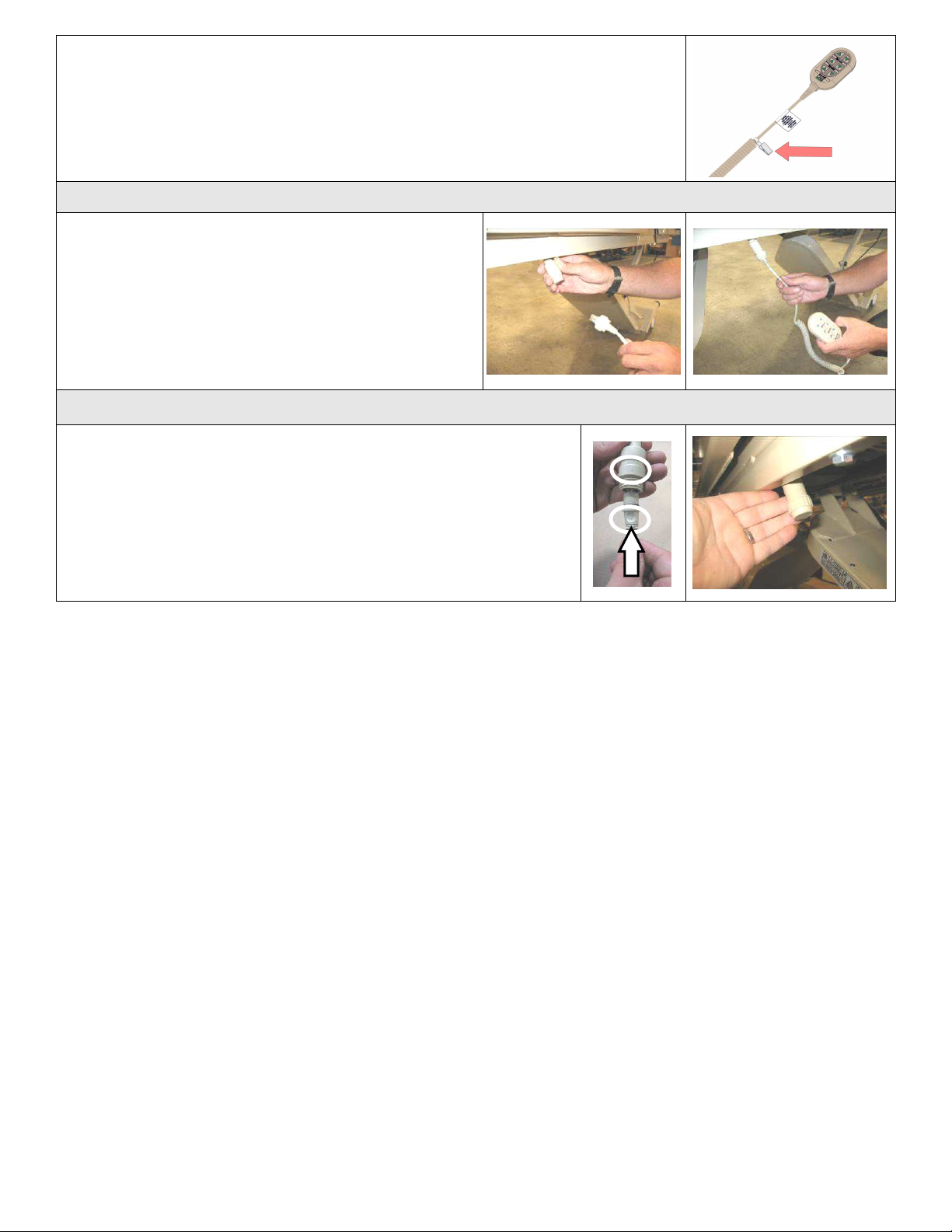
1-70-008 – H User Manual
- Spirit Plus 5600
CHG
Hospital
Beds
Page 45
of
103
Optionally, the pendant can be secured to the bed linens with the linen clip provided.
Choose a clip location so that the pendant is within easy reach by the patient.
Pendant Connection
The pendant can be connected on either side of the bed
(the connection port is just beneath the seat section of
the mattress deck on both sides of the bed). Only one
pendant can be connected to the bed at a time.
To relocate the pendant to the opposite side of the bed,
first, unscrew the threaded retaining cap then carefully
disconnect the jack. Reconnect the pendant control cable
to the existing port on the other side of the bed.
Pendant Port Alignment and Care
Ensure that the indexing arrows are aligned to enable connection.
Insert pendant cable into pendant port until O-ring seats into pendant
port and then thread on retaining cap to retain this connection.
To ensure that the pendant port remains free of dirt and debris,
ALWAYS cap any pendant port not in use. The threaded cap is simply
screwed onto the unused end of the pendant T-cable.
If you relocate the pendant to the other side of the bed, ensure that
you cap the unused pendant port.
Page 46
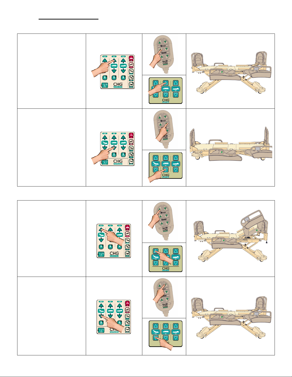
1-70-008 – H User Manual
- Spirit Plus 5600
CHG
Hospital
Beds
Page 46
of
103
3.4 Bed Positioning
3.4.1 Bed Elevation – HI-LO Operation
To raise the bed, press the
BED UP arrow on the
footboard staff control, the
rail staff controls, or on the
pendant.
Release the button when
the desired elevation has
been achieved.
To lower the bed, press
the BED DOWN arrow on
the footboard staff control,
the rail staff controls, or on
the pendant.
Release the button when
the desired elevation has
been achieved.
3.4.2 Head Deck (Back Rest) Elevation - Head Actuator Operation
To raise the head section
of the bed, press the HEAD
UP arrow on the footboard
staff control, the rail
staff/patient controls, or on
the pendant.
Release the button when
the desired elevation has
been achieved.
To lower the head section
of the bed, press the HEAD
DOWN arrow on the
footboard staff control, the
rail staff/patient controls,
or on the pendant.
Release the button when
the desired elevation has
been achieved.
Page 47
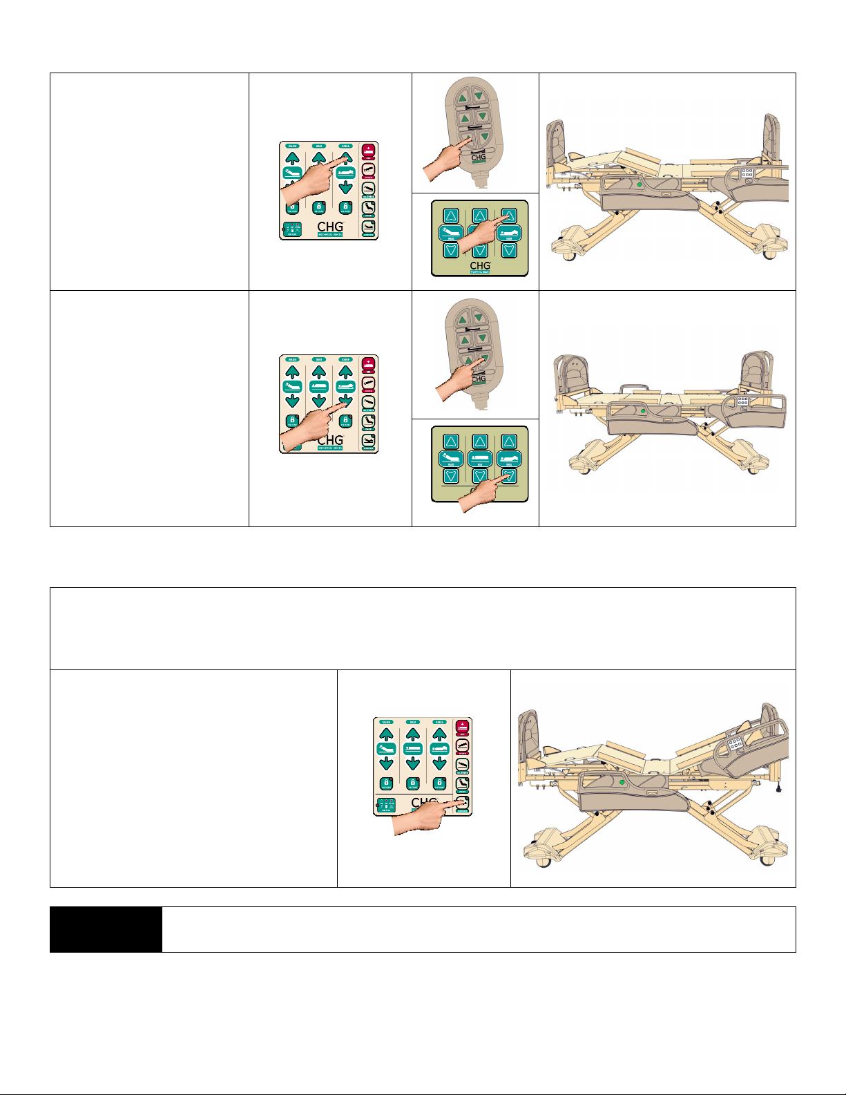
1-70-008 – H User Manual
- Spirit Plus 5600
CHG
Hospital
Beds
Page 47
of
103
3.4.3 Knee Deck Elevation - Foot Actuator Operation
To raise the knee section
of the bed, press the KNEE
UP arrow on the footboard
staff control, the rail
staff/patient controls, or on
the pendant.
Release the button when
the desired elevation has
been achieved.
To lower the knee section
of the bed, press the KNEE
DOWN arrow on the
footboard staff control, the
rail staff/patient controls,
or on the pendant.
Release the button when
the desired elevation has
been achieved.
3.4.4 Auto Contour Mode
When the head section of the mattress deck (back rest) is elevated, there is often the tendency for the
patient to slide towards the foot end of the bed. The Auto Contour Mode helps to prevent this motion. The
Auto Contour mode automatically raises/lowers the knee section to, correspondingly, whenever the head
section is raised or lowered.
To activate Auto Contour mode, simply
press the CONTOUR button. The green
LED in the top right corner of the button
will illuminate when the Contour mode
has been activated.
To deactivate Auto Contour mode,
simply press the CONTOUR button
again. If the CONTOUR button is not
illuminated, Auto Contour mode has
been deactivated.
NOTE:
Patient lock-out will override Auto Contour if the knee elevation lock-out has been
activated.
Page 48
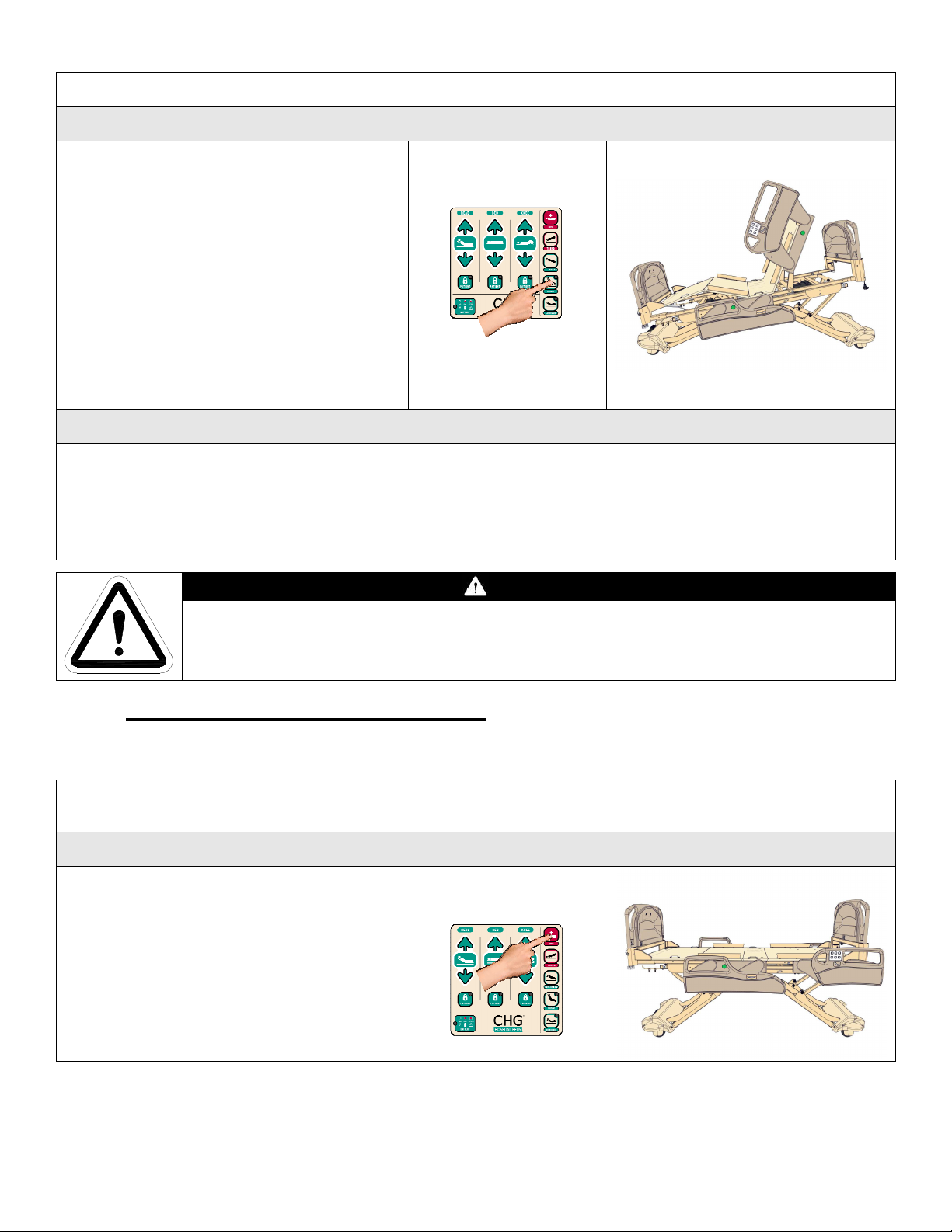
1-70-008 – H User Manual
- Spirit Plus 5600
CHG
Hospital
Beds
Page 48
of
103
3.4.5 Chair Positioning
the CHAIR button until the full chair position
The Chair position allows patient to be placed in an upright seating position.
To Achieve Chair Positioning
Simply press-and-hold the CHAIR button.
The bed will automatically articulate into the
chair position. The green LED in the top
right corner of the CHAIR button will
illuminate once the proper reverse
Trendelenburg angle has been achieved.
Release the CHAIR button anytime when
the desired chair position has been achieved
or the bed will stop automatically once the
full chair position has been achieved.
To Return the Bed to a Horizontal Position
Simply press-and-hold the CHAIR button until the bed is flat and level. The bed will stop automatically.
IMPORTANT: This will only work if the bed is in the full chair position (the green LED in the top right corner of
the CHAIR button is illuminated). Either continue to press-and-hold
is achieved, then release and press-and-hold the CHAIR button until the bed is flat and level or press-and-
hold the TREND button until the bed is level and press-and-hold the CPR button until the bed is flat.
CAUTION
The reverse Trendelenburg position is integral to Chair positioning configuration. The
Spirit™ bed may shift during reverse Trendelenburg activation. Attempt Chair positioning
only after the Central “Lock & Steer” system has been put in the “BRAKE” position.
3.5 Emergency & Staff Functions
3.5.1 Electronic CPR (Cardiopulmonary Resuscitation) Function
Activation of the Electronic CPR function allows press-and-hold flattening of the mattress deck allowing
staff to administer CPR to the patient.
Activation of the Electronic CPR Function on the Footboard Staff Control
Press-and-hold the CPR button on the
footboard staff control. The head and knee
sections will automatically lower to flat
position.
To interrupt the CPR function, simply release
the CPR button. Normal bed operation can be
resumed at any time. The Electronic CPR
function does not need be deactivated or reset.
Page 49
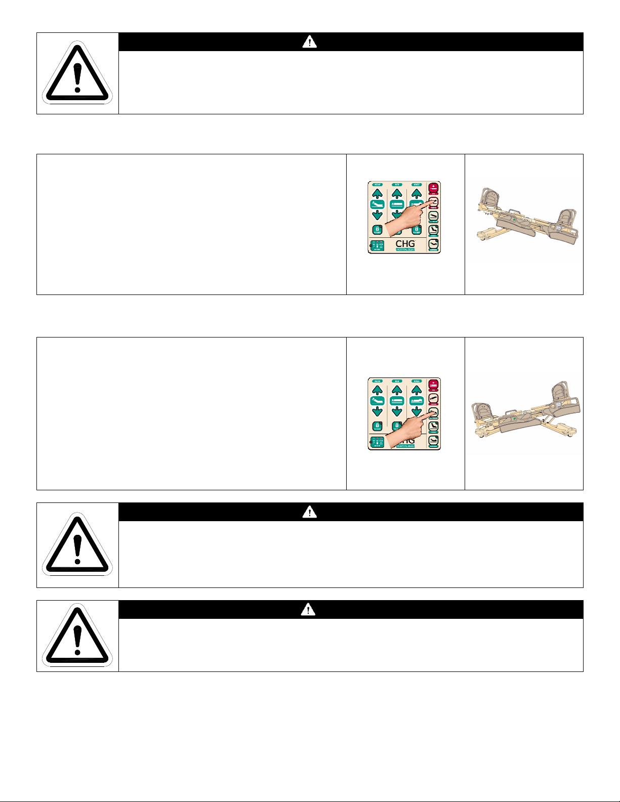
1-70-008 – H User Manual
- Spirit Plus 5600
CHG
Hospital
Beds
Page 49
of
103
CAUTION
Improper use of the Electronic CPR function may cause patient injury.
Once activated, Electronic CPR function will lower head and knee sections to flat position as
long as the CPR button is pressed. To interrupt Electronic CPR function, simply release the
CPR button.
3.5.2 Trendelenburg Operation
Press-and-hold the TREND button. Release the button
once the desired bed angle between 0° and 14° has been
achieved.
To return the bed to the horizontal position, press-and-
hold the rev.TREND button. The bed will automatically stop
when the mattress deck has returned to the horizontal
position.
The Trendelenburg angle is shown on the bed frame angle
gauge integrated on the staff side of both foot siderails.
3.5.3 Reverse Trendelenburg Operation
Press-and-hold the rev.TREND button. Release the button
once the desired bed angle between 0° and -14° has been
achieved.
To return the bed to the horizontal position, press-and-
hold the TREND button. The bed will automatically stop
when the mattress deck has returned to the horizontal
position.
The reverse Trendelenburg angle is shown on the bed frame
angle gauge integrated on the staff side of both foot
siderails.
CAUTION
Patient discomfort may result from normal operation of the Trendelenburg and reverse
Trendelenburg function.
Trendelenburg and reverse Trendelenburg modes should only be used on the advice of a
medical practitioner.
WARNING
The Spirit™ bed may shift during Trendelenburg or reverse Trendelenburg activation.
Initiate Trendelenburg or reverse Trendelenburg only after the Central “Lock & Steer”
system has been put in the “BRAKE” position.
Page 50
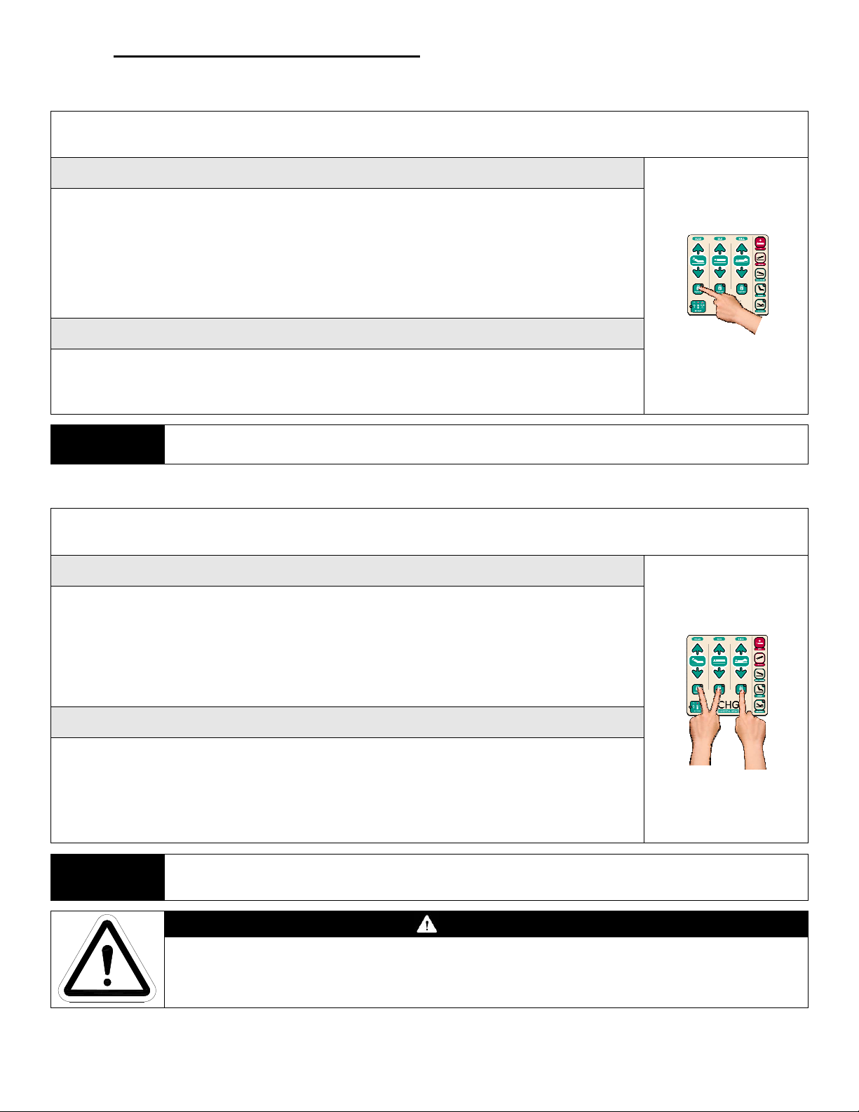
1-70-008 – H User Manual
- Spirit Plus 5600
CHG
Hospital
Beds
Page 50
of
103
3.6 Patient Lock-Out Functions
3.6.1 Regular Patient Lock-Outs
Patient Lock-Outs restrict the patient from initiating head, knee, and bed motion from the siderail controls or
the pendant (if equipped). The degree of restriction depends on the Lock-Out option selected.
Activating Patient Lock-Out
Staff may choose to restrict patient access to one, two, or all three bed functions.
To restrict a bed function, press the Patient Lock-Out button under that particular
function. The Lock-Out button indicator will illuminate when patient control of a
particular function has been Locked-Out.
IMPORTANT: Patient Lock-Outs restrict bed operation from both of the siderail
controls and pendant (if equipped).
Deactivating Patient Lock-Out
To deactivate any/all Patient Lock-Out(s), simply press the Patient Lock-Out
button(s) again. When a Patient Lock-Out button is no longer illuminated, patient
control of that particular function has been restored.
NOTE:
When Patient Lock-Outs have been activated, the footboard staff control remains fully active.
3.6.2 Master Lock-Out
To completely restrict access to all bed functions (except the Electronic CPR function) from all control
locations (staff and patient controls), use the Master Lock-Out function.
Activating Master Lock-Out
To activate the Master Lock-Out, press-and-hold all three Patient Lock-Out
buttons at the same time. All three Patient Lock-Out button indicators will flash
sequentially to indicate that Master Lock-Out has been activated.
IMPORTANT: Master Lock-Out restricts bed operation from all control locations
(both siderail controls and the footboard staff control).
Deactivating Master Lock-Out
To deactivate the Master Lock-Out function, simply repeat this process. Press-andhold all three Patient Lock-Out buttons at the same time. When all three Patient
Lock-Out buttons are no longer flashing sequentially, Master Lock-Out has been
deactivated and both staff and patient control from all control locations has been
restored.
NOTE:
When Master Lock-Out has been activated, the Electronic CPR function, Nurse Call, and the
underbed light remain operable.
WARNING
When a patient is left unattended, the bed should ALWAYS be lowered to its lowest
position and the bed elevation controls should be locked-out in order to reduce the risk of
patient injury.
Page 51
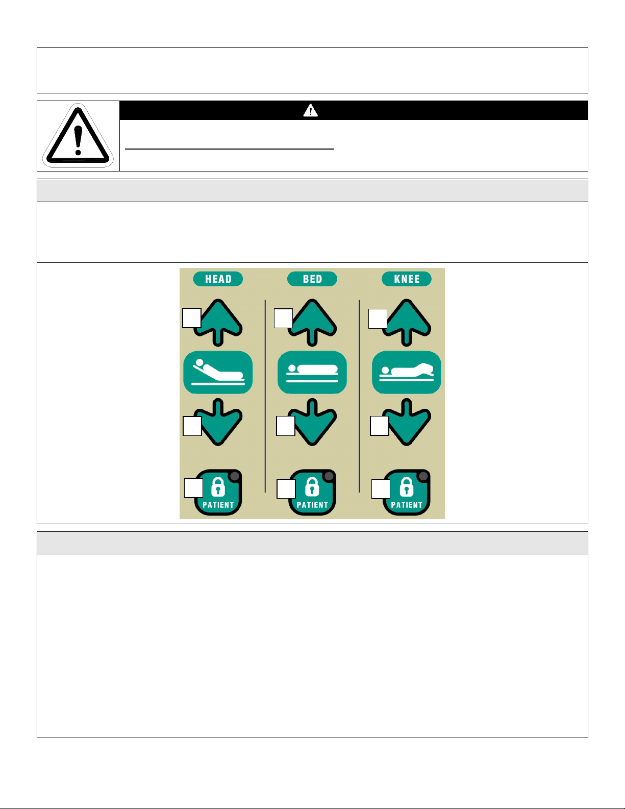
1-70-008 – H User Manual
- Spirit Plus 5600
CHG
Hospital
Beds
Page 51
of
103
3.6.3 Security Lock-Out
2 3
5 6
8 9
The Security Lock-Out feature allows for a high-security lock-out of ALL bed functions (including the
Electronic CPR function). A
Lock-Out feature must be activated or deactivated as required by the facility.
Activating the Security Lock-Out Feature
To deactivate the Security Lock-Out feature, a User Passcode must first be created. The User Passcode
must be between 1 and 6 digits long. The digits are interpreted from a virtual numeric keypad
superimposed over the footboard staff control buttons. Imagine the numbers 1 2 3, 4 5 6, 7 8 9, just as
they would appear on a telephone. This is demonstrated below.
“User Passcode”
is required to perform any/all bed functions. The Security
WARNING
IMPORTANT: When the Security Lock-Out feature has been activated, ALL bed operation
including the Electronic CPR function from any control location (footboard staff
control, both siderail controls, and pendant) is restricted.
1
4
7
Guidelines for Choosing a User Passcode
The number of digits chosen for the User Passcode will determine the level of security provided. A single
digit User Passcode is easy for staff to remember and unlock but offers virtually no security. A six digit User
Passcode offers very high security but may be a nuisance to staff.
• It is recommended that simple “lines” such as 1-2-3 or 1-4-7 are not chosen since they are relatively
easy to guess.
• It is recommended that the code contains at least one of the Patient Lock-Out buttons (7, 8, or 9)
since these buttons are not generally used during normal bed operation therefore adding an
enhanced level of security.
• Codes that contain repeating digits (i.e.: 1-3-1-7) can enhance security since they are considerably
less likely to be guessed.
• Codes that contain patterns of digits (i.e.: all four corners) can help staff remember the User
Passcode but offer slightly less security than random codes.
Page 52
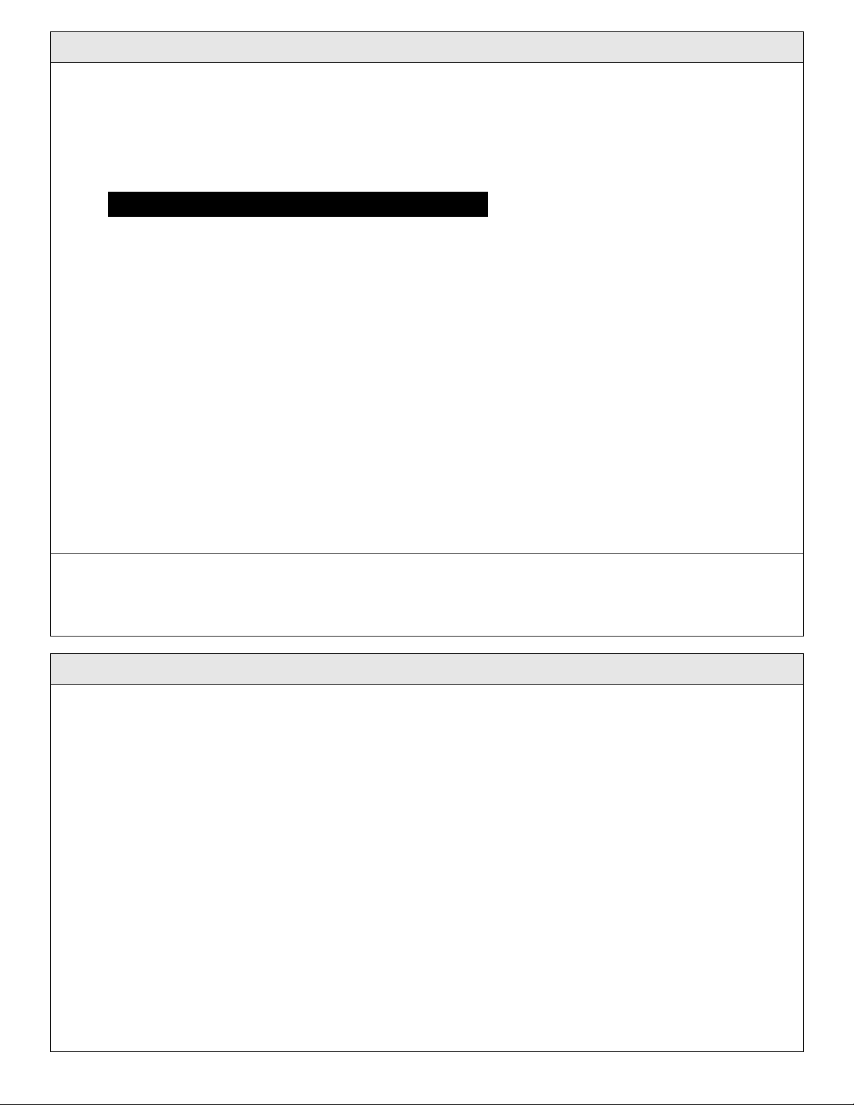
1-70-008 – H User Manual
- Spirit Plus 5600
CHG
Hospital
Beds
Page 52
of
103
Creating/Changing User Passcode
et up mode. An audible
To enable any/all bed functions, the bed must be unlocked.
A User Passcode must first be created before the Security Lock-Out feature can be activated.
To Create the User Passcode:
1. Press the Bed Lock-Out, Knee Lock-Out, and Contour buttons simultaneously. These three Lock-Out
buttons will then begin to flash to indicate that the bed is now ready to receive the Security Access Code.
2. Enter the Security Access Code.
Security Access Code: “1881 825 153”
IMPORTANT: This Security Access Code is factory set and is not customizable
3. Once the Security Access Code has been successfully entered, an audible “chirp” will sound three
times and the Contour button will also begin to flash to indicate that the bed is now ready to receive
the customized User Passcode.
4. Enter a 1 to 6 digit User Passcode of your choosing. Time-out will occur if more than 30 seconds
elapses between User Passcode digit input.
5. When the User Passcode has been entered, press the Contour button to complete the process. An
audible “chirp” will sound to indicate that the User Passcode has been set and that the Security LockOut feature has now been activated.
NOTE: DO NOT allow patients to learn either the Security Access Code or the User Passcode or the Security
Lock-Out feature could become compromised!
To Change the User Passcode:
In the event that the User Passcode has been lost or compromised, a new User Passcode can be created.
Simply repeat the above steps to change the User Passcode. The User Passcode can be changed as often as
required to maintain effective control of the Security Lock-Out feature
If, for some reason, you wish to abort the User Passcode creation/change procedure, simply press the Bed
Lock-Out, Knee Lock-Out, and Contour buttons simultaneously to exit User Passcode s
“chirp” will sound twice and the bed will return to its previous state (Security Lock-Out activated or
deactivated). The bed will also automatically return to its previous state after 30 seconds of keypad inactivity.
Locking/Unlocking the Bed for use by Staff
To unlock the Security Lock-Out:
1. Enter the 1 to 6 digit User Passcode.
2. Once the User Passcode has been successfully entered, an audible “chirp” will sound and the three
Patient Lock-Out buttons will begin to flash to indicate that the bed is now unlocked. All bed
functions are now available from all control locations (the footboard staff control and both siderail
controls).
IMPORTANT: There is no feedback during this step. If you make a mistake, or if nothing happens after the
User Passcode has been entered, simply re-enter the User Passcode starting at the first digit again There is
no need to “cancel” or abort the procedure if you make a mistake while entering the User Passcode as the
bed is “looking” only for the complete sequence of digits that comprise the User Passcode.
To re-lock the bed:
When you are finished adjusting the bed positions, press any one of the flashing Patient Lock-Out buttons to
re-lock the bed. An audible “chirp” will sound twice to indicate the bed has been re-locked.
OR
The bed will automatically re-lock after 30 seconds of keypad inactivity.
Page 53
1-70-008 – H User Manual
- Spirit Plus 5600
CHG
Hospital
Beds
Page 53
of
103
Deactivating the Security Lock-Out Feature
To restore normal bed operation (i.e.: full time control of bed functions from any control location), the
Security Lock-Out feature must be deactivated.
To deactivate the Security Lock-Out feature:
1. Press the Bed Lock-Out, Knee Lock-Out, and Contour buttons simultaneously. These three buttons
will then begin to flash to indicate that the bed is now ready to receive the Security Access Code.
2. Enter the Security Access Code (NOT the User Passcode).
3. Once the Security Access Code has been successfully entered, an audible “chirp” will sound three
times and the Contour button will begin to flash.
4. Press the Contour button. An audible “chirp” will sound twice to indicate that the Security Lock-Out
feature has now been deactivated.
WARNING
When the Security Lock-Out feature has been activated, the Electronic CPR function will
NOT work. The Security Lock-Out feature is only intended to be used by qualified medical
practitioners on a case-by-case basis based upon clinically assessed needs of the patient as
requiring a hospital bed having restricted motion. CHG Hospital Beds strongly recommends
that Security Lock-Out NEVER be activated when the bed is in normal ward use.
NOTE:
After a hard reset, all bed settings will be automatically restored. The Security Lock-Out
feature will be deactivated after a hard reset.
Page 54
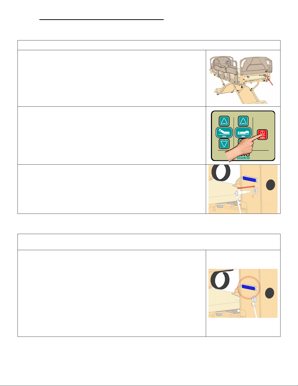
1-70-008 – H User Manual
- Spirit Plus 5600
CHG
Hospital
Beds
Page 54
of
103
3.7 Other Bed Functions & Features
3.7.1 Nurse Call
All Spirit™ beds are equipped with one Nurse Call port to accommodate Nurse Call control.
The Nurse Call port is located on the underside of the headboard mounting
bracket on the patient right side of the bed.
To operate the Nurse Call feature, press the red NURSE button on the rail
patient control (inside of each head rail control). This will send a Nurse Call
signal to the nurses’ station when appropriately connected to the
communication system of your healthcare facility.
Operation of the Nurse Call feature requires a conventional connection cable
(not supplied) to be plugged into the ¼” Phono jack on the headboard
mounting bracket and into the designated outlet in the patient station.
Ensure that the attached “dummy plug” is inserted to an inactive Nurse Call
port.
The “dummy plug” has an integral lanyard that is screw connected to the
headboard mounting bracket to ensure that the “dummy plug” is not lost
when the Nurse Call port is being used.
3.7.2 Standard 37 Pin Connector
All Spirit™ beds are equipped with a standard 37 pin connector to accommodate connection to the
communication system typical of most healthcare facilities.
The 37 pin connector is located on the underside of the headboard mounting
bracket directly beside the Nurse Call port on the patient right side of the
bed.
The “pin outs” for the 37 pin connector have been configured to work with
the communication set-up typical of most 37 pin enabled healthcare facilities.
If the configuration of the communication system used in your healthcare
facility differs from conventional set-up, successful interconnection can only
be guaranteed through the use of interconnection cables that have been
specifically configured for your application.
If your healthcare facility requires a particular interconnection cable
configuration, CHG Hospital Beds offers customized interconnection cables.
Contact your sales representative for details.
Page 55
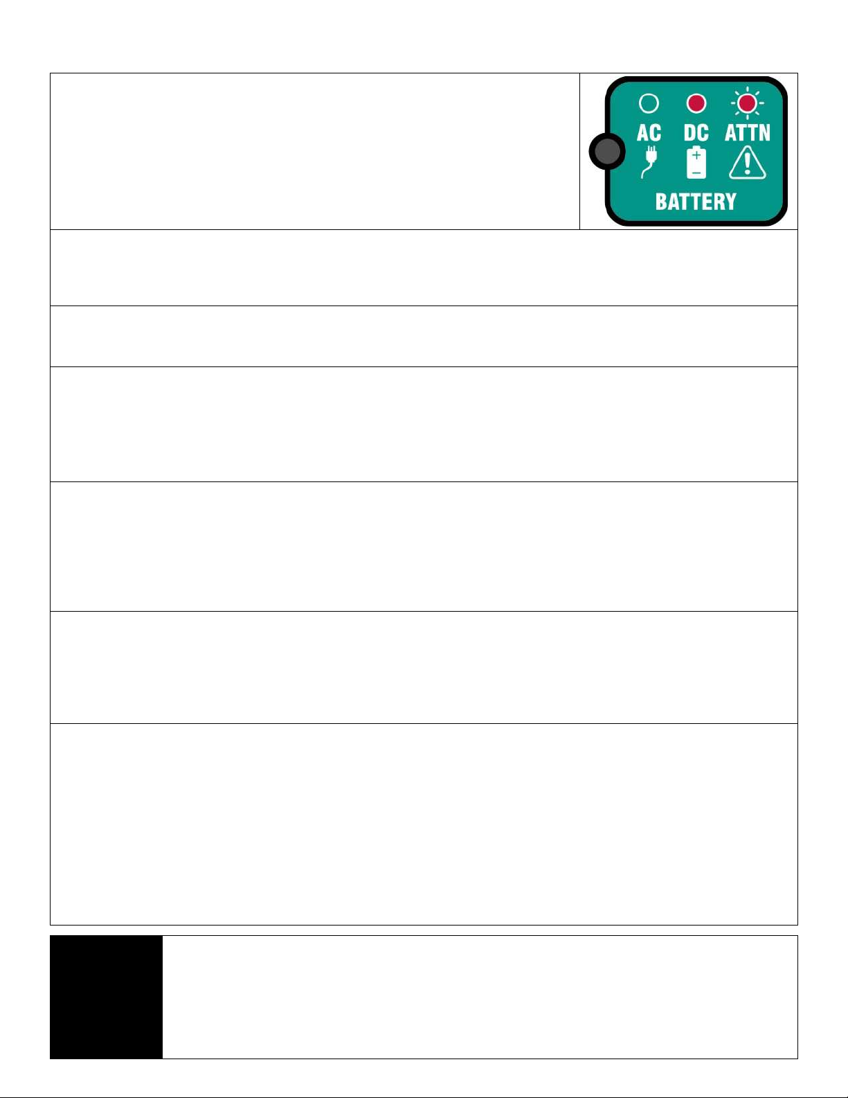
1-70-008 – H User Manual
- Spirit Plus 5600
CHG
Hospital
Beds
Page 55
of
103
3.7.3 Spirit Plus™ Power Status Indicator
Reconnect bed to an AC power outlet as soon as
The footboard staff control on Spirit Plus™ beds is equipped with an integrated power
status indicator. This cluster of 3 discrete icons indicates the real-time status of power
available to operate the bed. The icons will illuminate respective of the source of
power, the operation of the battery charging circuit, and the level of battery power.
The battery is continuously charged when connected to the CB10 control box and
the bed is plugged into an AC power outlet. If the battery voltage drops below
18VDC, battery power will be automatically disrupted to prevent further discharge
which could impact the battery’s ability to fully recharge. When the bed is plugged
back into an AC power outlet, battery power will be automatically restored.
Indicator LED is Solid GREEN
Bed is connected to an AC power outlet and operating on AC power. The battery is connected to the CB10 control box
and is fully charged. Bed is ready to operate on battery power if required. This is the optimum operating condition for
the bed.
Indicator LED is Flashing GREEN
Bed is connected to an AC power outlet and operating on AC power. The battery is connected to the CB10 control box
but is currently recharging.
Indicator LED is Alternating Flashing GREEN and RED
IMPORTANT: Bed may not reliably operate on battery power if required.
Bed is connected to an AC power outlet and operating on AC power. The battery is connected to the CB10 control box
but not holding proper charge. Service bed and/or replace battery immediately.
OR
The battery is not connected to the CB10 control box. Connect battery to CB10 and allow battery to charge for 24hr.
Indicator LED is Solid RED
Bed is disconnected from an AC power outlet and is operating on battery power. The battery is connected to the CB10
control box and has not yet exhausted the available battery power. Bed is OK to operate on battery power but it should
be connected to an AC power outlet as soon as is possible to recharge the battery.
IMPORTANT: Exercise caution when operating the bed on battery power. Ensure that only vital and necessary bed
functions are performed to extend battery power as long as possible and ensure emergency functions remain available
when needed.
Indicator LED is Flashing RED
Bed is disconnected from an AC power outlet and has been operating on battery power. Although the battery is
connected to the CB10 control box, it has exhausted its battery power.
possible and allow battery to charge for 24hr.
IMPORTANT: At this point, reliable bed operation cannot be guaranteed although some bed functionality may still be
available. Exercise caution operating the bed as the bed will cease operation without warning.
No Indicator LED illumination
IMPORTANT: Bed may NOT operate.
The bed has been disconnected from an AC power outlet and the battery is disconnected from the CB10 control box.
Reconnect bed to an AC power outlet and allow battery to charge for 24hr.
OR
The bed has a faulty connection or component (CB09 control box, CB10 control box, battery, and/or connection cable).
Confirm all connections and begin troubleshooting potentially faulty components.
OR
The bed has been disconnected from an AC power outlet and the battery has been automatically disengaged from the
battery circuit because the voltage has dropped below 18VDC. Reconnect bed to an AC power outlet and allow battery
to charge for 24hr.
NOTE:
A new back-up battery, when fully charged, has sufficient power to deliver the equivalent of
approximately 5 CPR cycles with a patient weight of 250 lbs. Battery power discharge rate depends
upon factors such as patient weight, age of battery, ambient temperature and humidity, and the
number of charge/discharge cycles the battery has been subjected to. For example, the heavier the
patient, the faster battery power will be exhausted during battery powered bed operation.
Conversely, the lighter the patient, battery power may offer a longer duration of battery powered
bed operation.
Page 56
1-70-008 – H User Manual
- Spirit Plus 5600
CHG
Hospital
Beds
Page 56
of
103
3.8 Siderail Operation
All Spirit™ bed siderail assemblies fully comply with FDA and Health Canada patient entrapment reduction
guidelines and have successfully passed rail entrapment testing using test procedures outlined by the Hospital
Bed Safety Workgroup. Spirit™ bed siderail assemblies were qualified using the Cone and Cylinder Tool as
specified by FDA and Health Canada patient entrapment reduction guidelines. Entrapment Test Kits are readily
available so on-going compliance can be monitored by the healthcare provider. For further information, refer
to the FDA’s website at http://www.fda.gov/cdrh/beds/.
3.8.1 Intended Application/Use of Spirit™ Bed Siderail Assemblies
When fully raised/closed and locked/latched in the UP position, the siderails define a residence area for
patients to rest upon the bed. This provides positive patient location/support helping to protect against the
potential for patients to fall from the bed as the siderails give the patient a visual and physical indicator of the
edge of the bed. When fully lowered/open in the DOWN position, the siderails permit patient ingress to and
egress from the bed. The integral handles common to all siderails facilitate patient mobility by providing a
gripping region during ingress to and egress from the bed.
WARNING
Safe Working Load of Siderails
80 kg (176 lbs)
DO NOT exceed a 80 kg (176 lbs) load on any siderail
WARNING
Possible PATIENT ENTRAPMENT if use of siderails that are damaged or modified in any way.
NEVER use siderails from other manufacturers and/or with dimensions different that the original
components and/or assemblies that came equipped with the bed. Variations in siderail design,
(width, height, shape, profiles, opening, locking/latching mechanisms, etc.) could cause/contribute to
patient entrapment and/or could potentially increase the probability/possibility for patient
entrapment.
CAUTION
DO NOT use the siderails as a patient lifting device/apparatus. Siderails can be deformed or broken
if excessive side loading/pressure is exerted. The siderails are used for the purpose of preventing a
patient from inadvertently rolling out of bed.
DO NOT use the siderails as part of a patient restraint mechanism. Siderails are NOT intended for
nor may be used for restraint purposes. If a patient is capable of inflicting self-injury or injury to
staff, a physician or other suitably trained healthcare practitioner should be consulted for alternate
means of safe patient restraint. The Spirit™ bed is equipped with at least 2 patient restraint loops for
this purpose.
CAUTION
When operating the bed, ALWAYS ensure that the individuals using the bed is positioned properly
on the mattress within the confines of the bed.
DO NOT let any patient extremities protrude over the side and/or between the siderails when
operating the bed.
CAUTION
DO NOT use the siderails as lifting points for the bed during transportation and/or storage.
DO NOT use the siderails as a means of mechanically restraining the bed during transportation
and/or storage.
Page 57
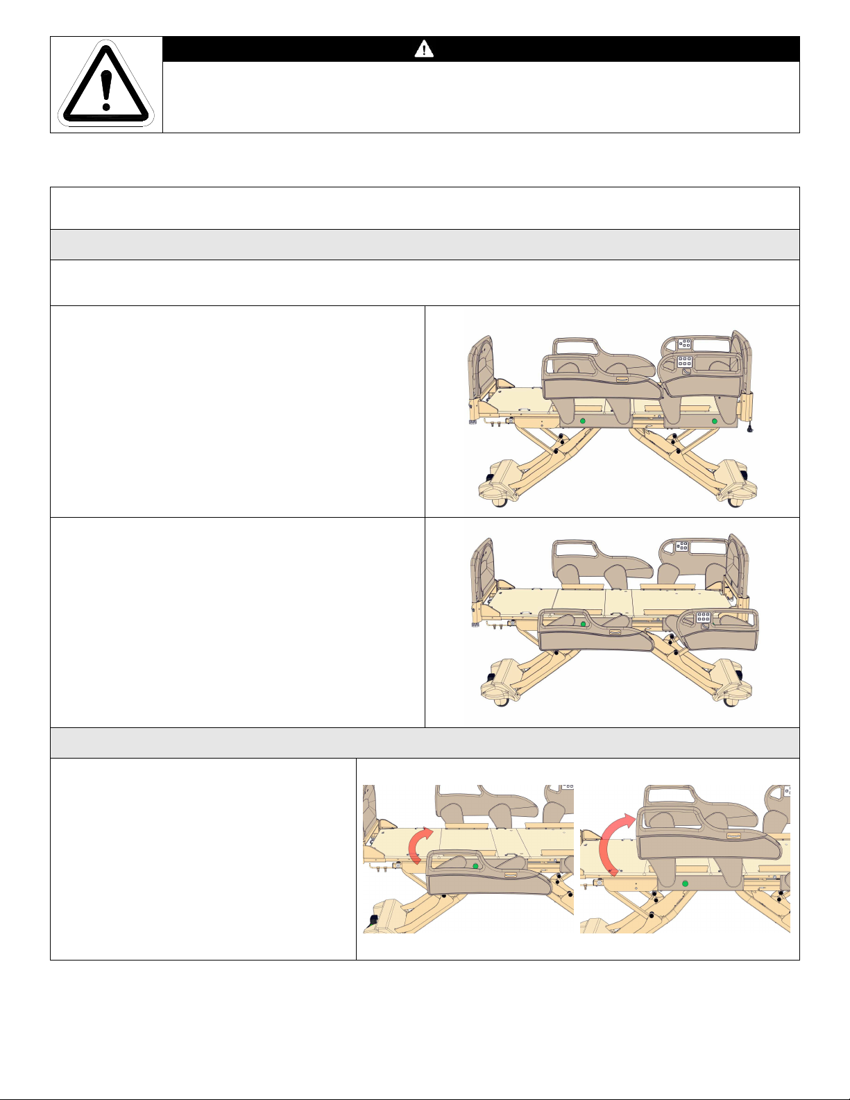
1-70-008 – H User Manual
- Spirit Plus 5600
CHG
Hospital
Beds
Page 57
of
103
CAUTION
DO NOT use a bed with damaged or non-latching rails. If a bed is found with damaged or nonlatching rails, remove bed from patient use and service bed immediately.
3.8.2 Plastic High Siderails
Your Spirit™ bed will be equipped with the moulded plastic high siderails*.
*Plastic high siderails come standard with CHG beige colour matched inlays. Your Plastic high siderails may have optional coloured inlays.
Operation of the Plastic High Siderails
It is important that caregivers know how to operate the plastic high siderails safely. The high siderails lock
in the UP position and enables patient ingress, egress, and transfer in the DOWN position.
In the UP position, the high siderails provide positive
patient location and support helping to protect the
patient from the potential of falling from the bed.
IMPORTANT: An audible “click” should be heard
when each high siderail assembly has been
completely rotated into the UP position as the
locking/latching mechanism engages.
The DOWN position, the high siderails fully rotate
out of the way to provide unimpeded and unassisted
patient ingress to and egress from the bed and also
enables patient transfer by staff.
IMPORTANT: The high siderails will not lock/latch
in the DOWN position.
Raising the High Foot Siderails
Gently rotate the high foot siderail to the
UP position. The high foot siderail will first
arc toward the foot end of the bed then
back towards the head end of the bed as it
rotates to the UP position.
IMPORTANT: An audible “click” should
be heard when the high foot siderail has
been completely raised to the UP position
as the locking/latching mechanism
engages.
Page 58
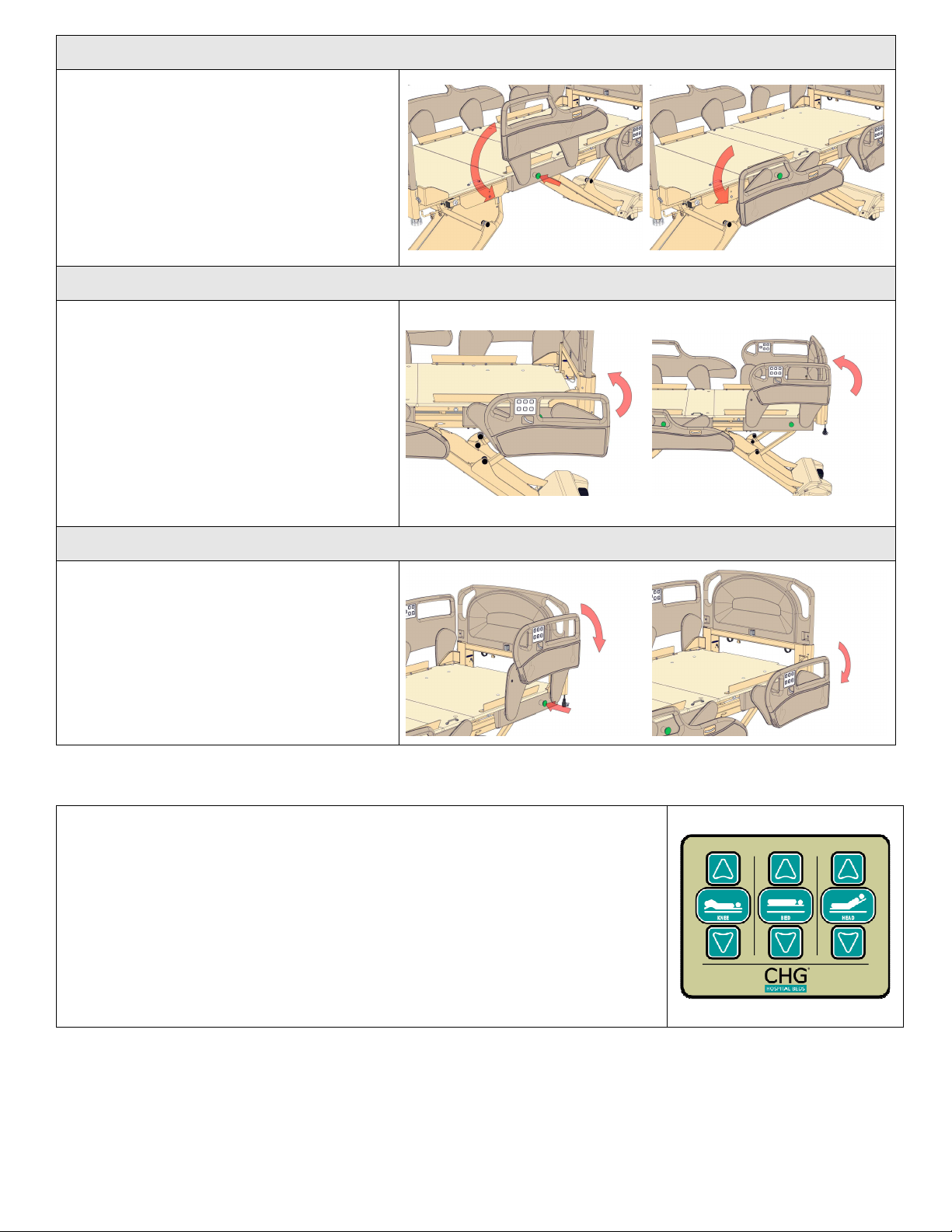
1-70-008 – H User Manual
- Spirit Plus 5600
CHG
Hospital
Beds
Page 58
of
103
Lowering the High Foot Siderails
Depress the green PRESS button then
gently PRESS down on the high foot
siderail. The high foot siderail will first arc
towards the foot end of the bed then back
towards the head end of the bed as it
rotates to the DOWN position.
IMPORTANT: The high foot siderails will
not lock/latch in the DOWN position.
Raising the High Head Siderails
Gently rotate the high head siderail to the
UP position. The high head siderail will
first arc toward the head end of the bed
then back towards the foot end of the bed
as it rotates to the UP position.
IMPORTANT: An audible “click” should be
heard when the high head siderail has
been completely raised to the UP position
as the locking/latching mechanism
engages.
Lowering the High Head Siderails
Depress the green PRESS button then
gently PRESS down on the high head
siderail. The high head siderail will first
arc towards the head end of the bed then
back towards the foot end of the bed as it
rotates to the DOWN position.
IMPORTANT: The high head siderails will
not lock/latch in the DOWN position.
3.8.3 Integrated Features of High Siderails
Staff Siderail Controls
The head siderails incorporate integrated staff control that offers staff control
of basic bed operations:
• Head UP/DOWN,
• Knee/Foot UP/DOWN
• Bed UP/DOWN
IMPORTANT: Bed operation from this siderail control is disabled when the
patient lock-outs are activated.
Page 59
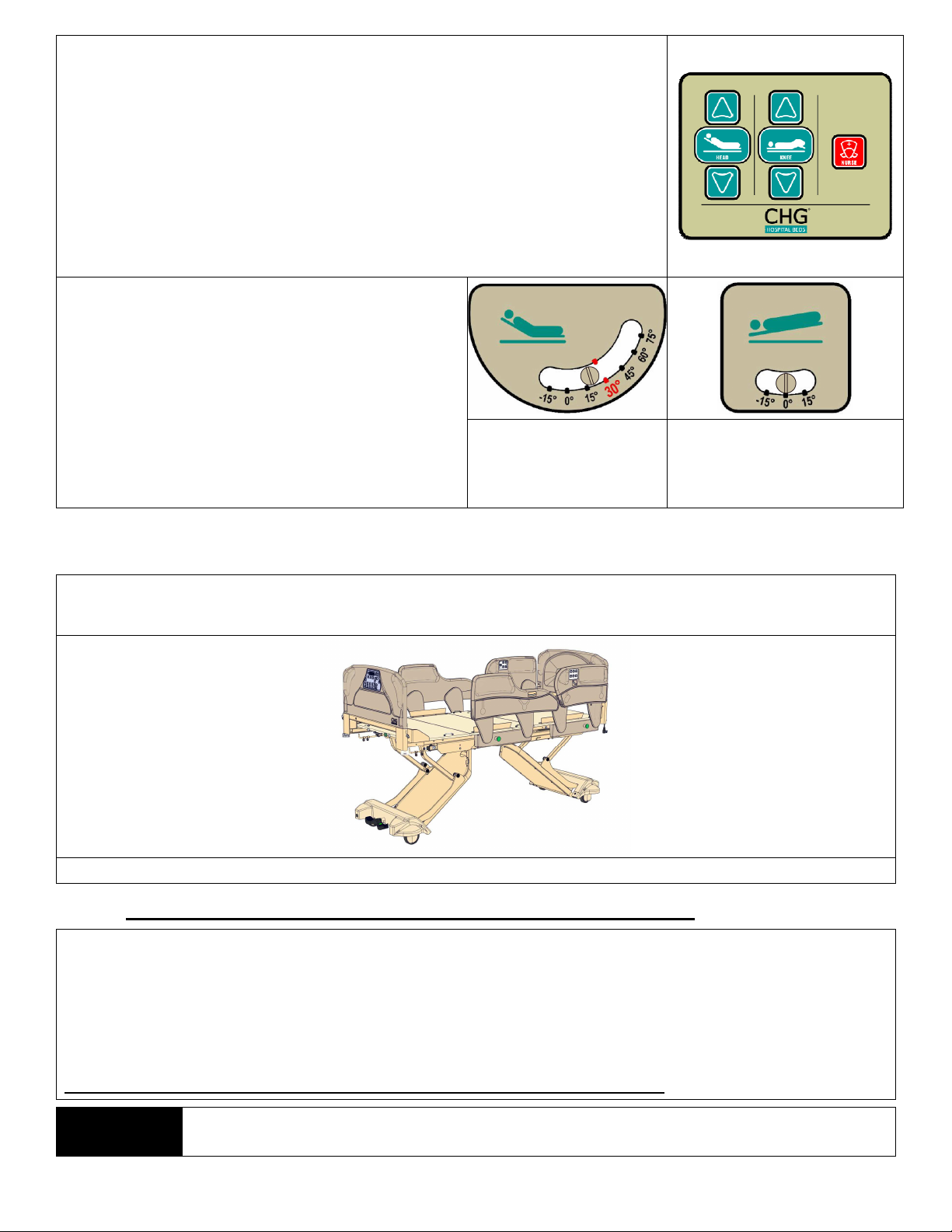
1-70-008 – H User Manual
- Spirit Plus 5600
CHG
Hospital
Beds
Page 59
of
103
Patient Siderail Controls
The head siderails incorporate integrated patient control that offers patient
control of basic bed operations:
• Head UP/DOWN,
• Knee/Foot UP/DOWN
• Nurse Call feature
IMPORTANT: Bed operation from this siderail control is disabled when the
patient lock-outs are activated however the Nurse Call feature always
remains active.
Angle Gauges
All four siderails have integrated angle gauges:
• The angle gauge in the head siderail panel
displays the angle of the head section of the
mattress deck.
•
The angle gauge in the foot siderail panel
displays the Trendelenburg or reverse
Trendelenburg angle.
Head Angle Gauge
Trend or rev Trend
Angle Gauge
3.8.4 Other Optional Siderails
Your Spirit™ bed may be equipped other optional moulded plastic siderails as shown below.
IMPORTANT: These other optional siderails operate exactly the same as described above.
Plastic High Head Siderails (“Filled-in” version with beige inlays shown)
3.9 Optional Underbed Light on Spirit Plus™ Beds
Spirit Plus™ beds can be equipped with integrated underbed lighting as an option however the underbed
light cannot be deactivated using the footboard staff control. If the underbed light needs to be deactivated,
both of the underbed lights need to be disconnected from the CB10Lite control box. Refer to page 79 to
identify the two connectors for the underbed lights:
• To disable the underbed lights, disconnect both of the light connectors from the LT1 and LT2 headers on
The ONLY setting for the underbed light: LOW brightness ALWAYS ON.
NOTE:
the CB10Lite circuit board.
Underbed lighting WILL NOT function (illuminate) when the bed is operating under battery
power. This is to reserve battery power for emergency functions.
Page 60
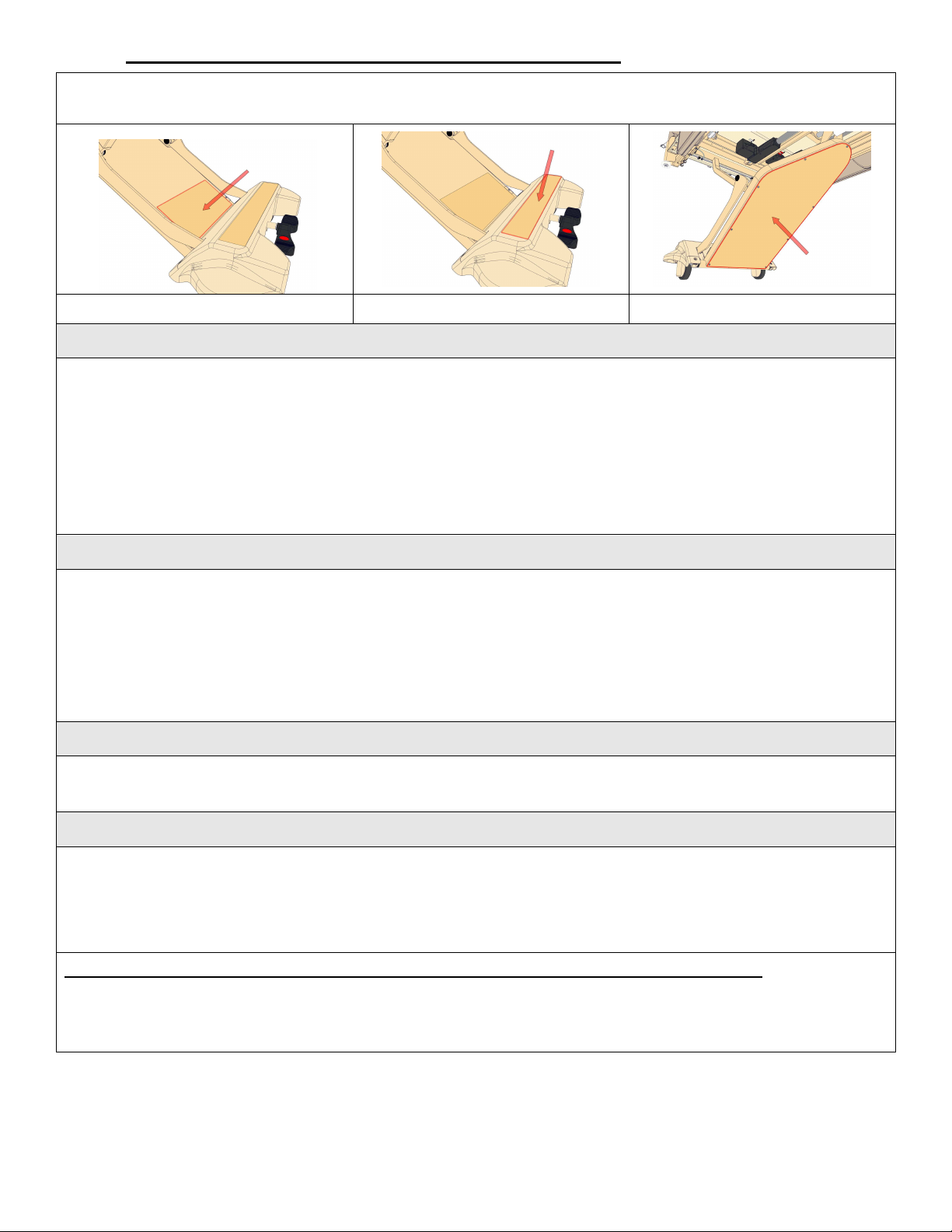
1-70-008 – H User Manual
- Spirit Plus 5600
CHG
Hospital
Beds
Page 60
of
103
3.10 Optional Underbed Obstruction Sensors
tion or if an obstruction is detected prior to any bed lowering
If your Spirit™ bed has been equipped with the optional underbed obstruction sensors, the bed will be
outfitted with 6 obstruction sensors as shown below.
Top Cover Obstruction Sensor
Caster Cover Obstruction Sensor Bottom Cover Obstruction Sensor
Contact with an Obstruction While the Bed is in Downward Motion
When an obstruction is detected during any downward motion of the bed (using any of the following: BED
DOWN, TREND, rev.TREND, LEVEL ALL, or CHAIR position), the bed will immediately stop all downward
motion and the bed platform will automatically elevate up for one second. This will provide clearance for
removal of the obstruction.
• An audible “chirp” will sound to indicate an obstruction is present.
Any further attempts to initiate downward motion of the bed platform will not be permitted if an obstruction
is still being detected and the bed platform will emit an audible “chirp” after each attempt.
Contact with an Obstruction While Bed is Stationary (i.e.: Bed not in Motion)
When an obstruction is detected prior to any bed movement, all downward motion of the bed (using any of
the following: BED DOWN, TREND, rev.TREND, LEVEL ALL, or CHAIR position) will be automatically
disabled.
• An audible “chirp” will sound to indicate an obstruction is present.
Any further attempts to initiate downward motion of the bed platform will not be permitted if an obstruction
is still being detected and the bed platform will emit an audible “chirp” after each attempt.
When an Obstruction is not Detected (i.e.: Obstruction Removed)
When an obstruction is no longer detected:
• Normal bed operation will be restored.
Audio Indicators
Audio Obstruction Indicator:
When an obstruction is contacted during bed mo
motion and a downward motion of the bed platform (using any of the following: BED DOWN, TREND,
rev.TREND, LEVEL ALL, or CHAIR position) is attempted an audible “chirp” will sound.
The factor default setting for obstruction sensors is CONNECTED and OPERATING. This cannot be
changed using the footboard staff control. The obstruction sensors can only be enabled/disabled by
connecting/disconnecting the obstruction sensor circuits from the CB10Lite circuit board. Refer to page 79 to
identify the two connectors for the obstruction sensor circuits.
Page 61
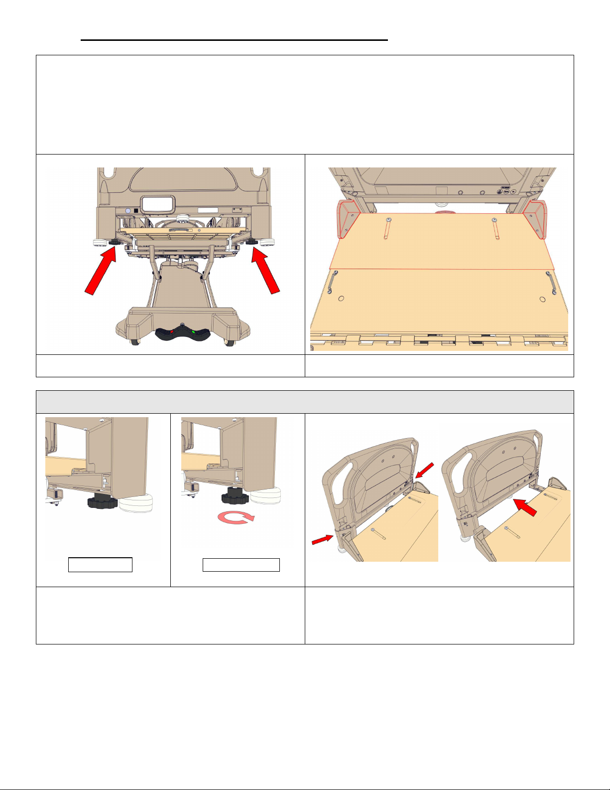
1-70-008 – H User Manual
- Spirit Plus 5600
CHG
Hospital
Beds
Page 61
of
103
3.11 Optional “Easy Bed” Extension System
To accommodate the physical needs of taller patients, while maintaining the easy of frequent bed movement
about space confined healthcare facilities, CHG Hospital Beds offers an optional “Easy Bed” extension system
that allows for easy and rapid extension/retraction of the mattress deck by 4 inches (102 mm) from 80”
(2032 mm) to 84” (2134 mm). No tools are required to perform bed “Easy Bed” extension/retraction
operations.
If your Spirit™ bed has been equipped with the optional “Easy Bed Extension” system, the bed will be
outfitted with two clamping knobs and an extendable foot deck section of the mattress deck as shown below.
Clamping Knobs
(viewed from foot end of bed)
Bed Extension Procedure
Knob clamped
1. Elevate bed to comfortable working height.
Unclamp the footboard bracket slide mechanism
by turning both knobs counter-clockwise until they
stop turning freely.
Knob unclamped
Extendable Foot Deck Section
2. Grasp footboard bracket by the corners as shown
above. Gently and smoothly pull away from the
head of the bed until the footboard bracket slide
mechanism contacts its mechanical stops.
Page 62
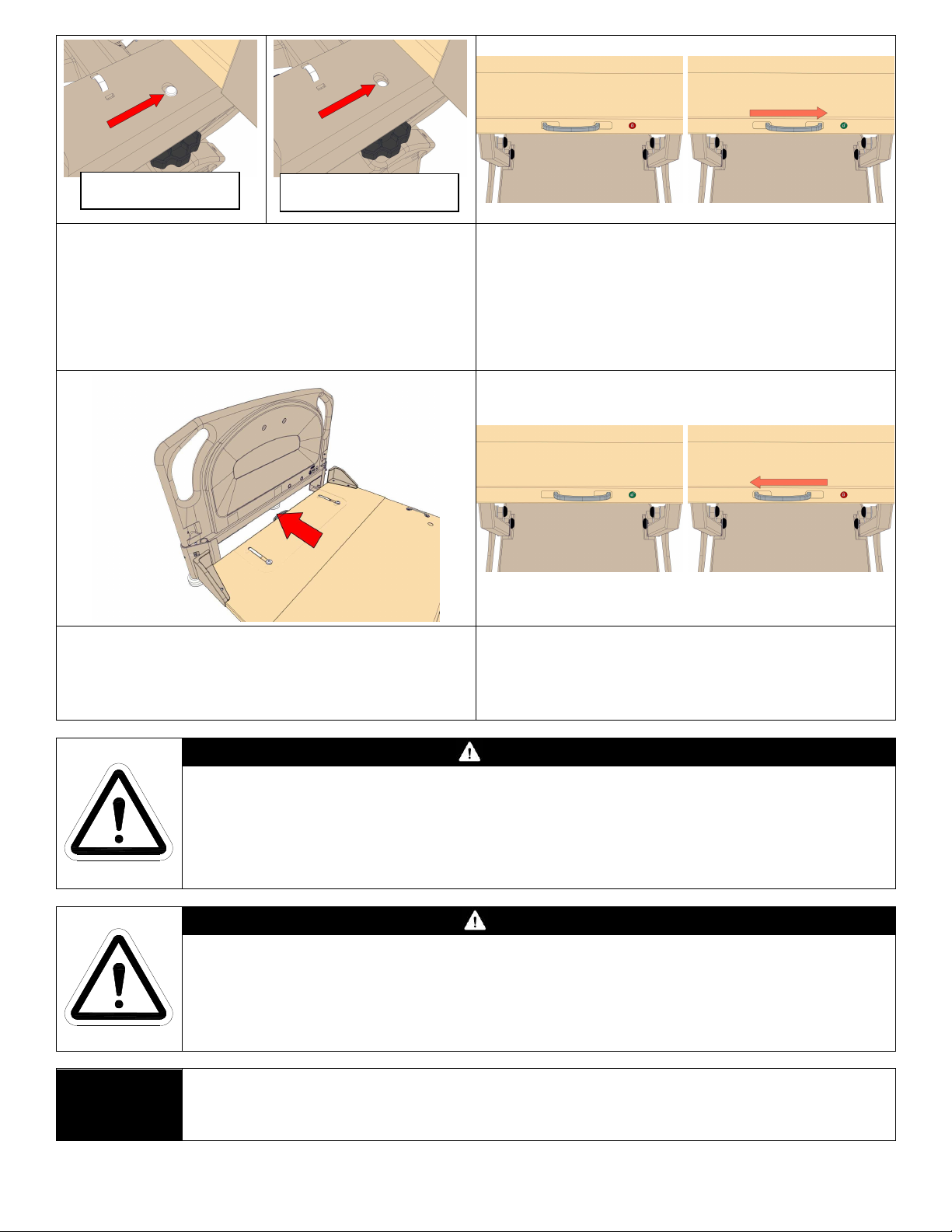
1-70-008 – H User Manual
- Spirit Plus 5600
CHG
Hospital
Beds
Page 62
of
103
Knob fully clamped (knob
fastener fully engaged)
Knob not fully clamped (knob
fastener not fully engaged)
3. Clamp the footboard bracket slide mechanism by
turning both retention knobs clockwise until hand
tight.
IMPORTANT: Ensure that the clamping knob
fastener extends through the retention hole located
in the footboard bracket channel. Typical both sides.
5. Grasp the chrome handle as shown at right. Gently
and smoothly pull away from the head end of the
bed until the foot deck extension pan contacts its
mechanical stops.
4. Unlock foot deck extension pan by grasping the
chrome handle and sliding the locking mechanism
towards the patient left side of the bed to the
unlocked position (green, unlocked icon)
6. Lock foot deck extension pan by grasping the
chrome handle and sliding the locking mechanism
towards the patient right side of the bed to the
locked position (red, locked icon).
NOTE:
WARNING
Possible PATIENT ENTRAPMENT Hazard could occur if the mattress is not securely
located and retained on the mattress deck by the four corner mattress keepers.
NEVER perform a bed extension/retraction with a patient on the bed.
NEVER place a patient on the bed if the mattress is not properly located and retained on
the mattress deck by the four corner mattress keepers.
CAUTION
Possible UNEXPECTED MOTION could occur if the slide lock is not in the “lock” position
and the mattress deck is articulated from the horizontal position.
When the bed is in either the extended or retracted position, the clamping knob fasteners
MUST be fully engaged and the slide lock MUST be in the “lock” position prior to placing a
patient on the bed and/or allowing a patient to return to the bed.
Bed retraction procedure is the same as the above except that the footboard bracket and
the foot deck extension pan are pushed towards the head end of the bed until contact is
made with their respective mechanical stops.
Page 63
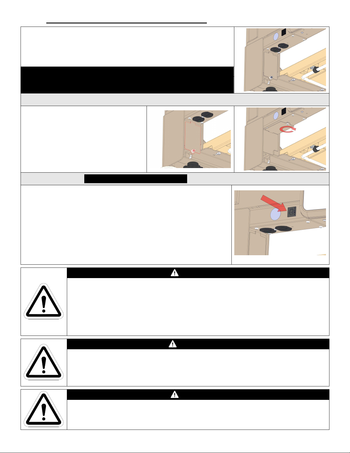
1-70-008 – H User Manual
- Spirit Plus 5600
CHG
Hospital
Beds
Page 63
of
103
3.12 Optional Auxiliary AC Power Outlet
NEMA 5-15R Outlet Socket configuration shown
All Spirit™ beds can be equipped with an optional auxiliary AC power outlet
mounted in the patient right side of the footboard bracket.
IMPORTANT: The auxiliary AC power outlet has the following electrical ratings:
MAXIMUM Output Power Rating: 120 Volts AC, 600 Watts
DO NOT EXCEED MAXIMUM OUTPUT POWER RATING
Auxiliary AC Power Outlet Cover
The auxiliary AC power outlet has a cover
that is integrated into the footboard bracket.
The attachment screw is retained with a
nylon nut so that it will not be misplaced
when the auxiliary outlet is in use.
IMPORTANT: Always install the cover over
the auxiliary AC power outlet when it is not
in use.
Circuit Breaker: Rating 5 Amps (120V Beds)
The auxiliary AC power outlet socket is protected by a circuit breaker. The
circuit breaker is located in the footboard bracket. The circuit breaker is the
resettable type. Simply depress the button to re-engage the circuit breaker.
IMPORTANT: The circuit breaker is a safety device that is designed to
disengage an electrical circuit when the load exceeds the maximum rating of
the circuit. An overloaded circuit may cause irreparable damage to the AC
power wiring in the bed. If the circuit breaker trips, it is important to
understand what has happened to cause this event. The device(s) that is/are
connected to the bed may be drawing too much power and exceeding the
circuit breaker rating.
CAUTION
The auxiliary AC power outlet socket is rated for a MAXIMUM 120 Volts AC, 600 Watts output
power. DO NOT exceed the maximum output power rating.
DO NOT use the auxiliary AC power outlet socket if the socket receptacles appear to be damaged
and/or if the plug (of the device that you are connecting to the bed) does not remain connected
when inserted in the outlet socket receptacles.
Only replace this outlet socket with a NEMA 5-15R duplex outlet socket that is marked as hospital
grade. Contact Stryker Medical Technical Service for a replacement outlet socket.
WARNING
A circuit breaker is NOT designed to act as a ground fault circuit interrupter (GFCI) and DOES NOT
offer the same level of protection. The circuit breaker is a safety device that is designed to only
disengage an electrical circuit when the load exceeds the maximum rating. If the circuit breaker trips,
discontinue bed use immediately and have a service technician, specifically trained to service Spirit™
beds, inspect the wiring. Circuit Breaker Rating: 5 Amps (120V beds)
CAUTION
Connecting electrical equipment to auxiliary mains AC outlet effectively leads to creating a medical
equipment system and can result in a reduced level of safety. When connecting devices, the system
shall be evaluated in end use application to ensure compliance to medical device standard 60601-1
and 60601-1-1.
Page 64

1-70-008 – H User Manual
- Spirit Plus 5600
CHG
Hospital
Beds
Page 64
of
103
Section 4:
Care & Maintenance
Page 65
1-70-008 – H User Manual
- Spirit Plus 5600
CHG
Hospital
Beds
Page 65
of
103
4.1 Regular Maintenance & Cleaning
CHG Hospital Beds recommends that bed inspections be conducted as per 4.1.2 and 4.1.3 of this section, or
more frequently if so specified by the facility procedures and practices.
All metal components are power coat painted and therefore are protected from corrosion. In the event that
the paint become scratched or chipped, use a matching enamel touch up paint. Refer to page 72 for paint
specifications.
CAUTION
Equipment or property DAMAGE or patient INJURY may occur if the following are not followed:
DO NOT submerge the bed frame or electrical parts. DO NOT allow liquids to enter
electrical components. If a liquid is spilled in or around the bed, unplug the bed before
cleaning. Clean up the spill and allow the bed and/or the area around the bed to dry
thoroughly before using the controls again.
DO NOT open assemblies such as actuators, control boxes, battery, or pendant (if
equipped). These parts are not serviceable. Only service technicians, specifically trained to
service Spirit™ beds, should attempt to service bed and/or replace electrical or other
components.
Before the bed is returned to active service after any adjustment, repair, and/or service
have been performed, ALWAYS ensure that all attaching hardware is tightened securely.
4.1.1 Cleaning & Disinfection
CHG Hospital Beds recommends that all cleaning/disinfection be performed by hand using a non-abrasive
cloth, sponge, and/or manual spray/squirt bottle. ALWAYS follow industry best practices for all cleaning
and/or disinfection operations. ALWAYS reference the manufacturers' MSDS information for all
cleaning/disinfection solutions prior to use.
IMPORTANT: The Spirit™ bed is not rated for spray and/or pressure washing or steam cleaning/sterilization.
Using non-recommended cleaning/disinfecting solutions, and/or not following recommended handling
directions and/or industry best practices may cause damage to the bed’s painted finish, bed components,
and/or may result in premature mattress failure.
Cleaning
All Spirit™ bed surfaces may be cleaned with soapy water and/or other non-abrasive cleaners. NEVER use
solvents, petroleum products, and/or other harsh chemicals to perform any cleaning operation.
Disinfection
All Spirit™ bed surfaces may be disinfected with ethanol or isopropyl alcohol, and/or Mikro Quat™ (or
equivalent cleaning solution). Sodium Hypochlorite (liquid bleach) may also be used to disinfect the Spirit™
bed and the CHG Prevention Surface mattress cover.
Maximum Recommended Sodium Hypochlorite Concentration: 0.5% or 5,000 ppm
To disinfect the Spirit™ bed, saturate an application cloth with disinfecting solution and wipe surface(s).
Using another cloth saturated with potable (tap) water, rinse disinfected surface(s) and wipe dry. DO NOT
allow the disinfecting solution to pool and/or reside on surface(s) for extended periods of time. Exceeding
the maximum recommended concentration and/or using non-recommended disinfecting solutions may cause
damage to the bed’s painted finish or bed components.
Page 66
1-70-008 – H User Manual
- Spirit Plus 5600
CHG
Hospital
Beds
Page 66
of
103
4.1.2 Semi Annual Inspections
Confirm
the following:
Inspect the bed for broken, bent, or damaged components and replace. Check for damaged components
Inspect actuators to ensure enclosures are not cracked or damaged. Inspect mounting points to ensure they
Control Location Inspection
Perform all bed functions from all control locations: footboard staff control, patient/staff siderail controls,
and pendant (if equipped).
Battery Inspection
• Bed is plugged into an AC power outlet.
• Battery is connected to the CB10 control box.
• The power status indicator has ONLY a solid Green AC light.
If other light are on/flashing, refer to page 55 for instructions and take appropriate action before continuing
with inspection.
Unplug the bed from the AC power outlet and perform all bed functions, including emergency functions, to
test bed operation under battery power.
This will verify that the battery is holding a proper charge sufficient to deliver emergency functions when
needed. Replace battery if performance is inadequate.
If your Spirit™ bed is equipped with the under bed obstruction sensing option, perform an inspection of all
six obstruction sensor pads to ensure that they are in good working order and continue to operate properly.
Obstruction Sensor Inspection
Ensure that contact at any point on each of the six obstruction sensor pads stops all downward bed motion.
Ensure that the bed automatically elevates the 1” safety distance.
Ensure audible warnings are present as described on pages 60.
Replace any obstruction sensor pad that fails to operate correctly or consistently.
4.1.3 Yearly Inspections & Maintenance
that may present a hazard due to sharp edges.
Inspect for damaged or loose wiring. Have qualified service personnel, specifically trained to service Spirit™
beds, replace any frayed or damaged cords and/or secure any loose wiring.
Inspect the control boxes to ensure that the enclosures are not cracked or damaged and all fasteners remain.
Inspect actuator guard bracket for any signs of deformation, excessive wear or damage.
are securely fastened to bed frame and leg assemblies.
Inspect the head-end and foot-end leg assemblies for any bend or damage
Inspect the footboard staff control, side rail controls, and pendant to ensure that the overlays covering these
controls are not cracked or damaged.
Inspect all grounding wires and equipotential conductor. Ensure they are securely fastened to the bed
frame.
Tighten, adjust and/or replace any parts or screws, bolts, clevis/hitch/cotter pins, etc. that are loose or show
signs of wear.
Page 67
1-70-008 – H User Manual
- Spirit Plus 5600
CHG
Hospital
Beds
Page 67
of
103
Using white petroleum jelly, lubricate between the Hi-Lo springs and the spring bushing. Apply white
Perform inspection of side
rails to ensure that they are in good working order an
d continue to operate
petroleum jelly to rail bracket slots, ensuring the shoulder bolt receives lubrication as well.
Spray metal shoulder bolts, washers, bushings and nuts using a high-quality penetrating white lithium
grease spray on all control arm and suspension arm joints
properly per the standards found in the technical specifications.
High Side Rail Inspection
Ensure that each side rail fully and smoothly rotates from the DOWN position to the UP position. Ensure that
no binding and/or grinding noises are caused when the side rails are rotated. If a side rail fails to rotate fully
and smoothly, service and/or replace side rail assembly.
Ensure that the locking/latching mechanism reliably self-engages when the side rails are fully rotated to the
raised/closed position. If locking/latching mechanism fails to reliably self-engage service and/or replace side
rail assembly.
Ensure that the locking/latching mechanism completely disengages when the PRESS button is depressed
permitting the side rails to fully rotate to the lowered/open position. If locking/latching mechanism fails to
completely disengage service and/or replace side rail assembly.
WARNING
Patient entrapment within, under, between, and beside side rails may cause injury or death.
Ensure only specified mattress (minimum 6” thick) is used on bed. Ensure that mattress is
in good condition and maintains proper resilience. If mattress is exhibiting any signs of
wear (i.e.: reduced cross sectional thickness, reduced resilience, etc.) stop use immediately
and replace mattress to limit patient exposure to a potential rail entrapment situation.
WARNING
To help minimize the potential for patient entrapment, CHG Hospital Beds recommends that
the customer perform thorough inspection of all side rail assemblies to confirm continued
compliance per the standards found in the technical specifications. If testing results indicate
a potential risk of patient rail entrapment, discontinue patient bed use and remove the bed
from active service immediately.
Page 68
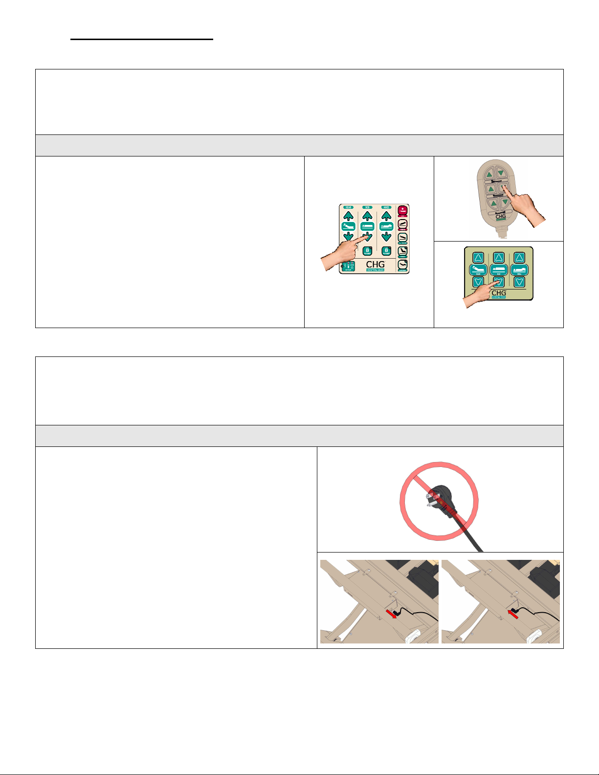
1-70-008 – H User Manual
- Spirit Plus 5600
CHG
Hospital
Beds
Page 68
of
103
4.2 Controls Servicing
4.2.1 Soft Reset of Controls
If in the rare event that the two Hi-Lo actuators become out-of-sync with one another, the bed may not
completely lower or the mattress deck on the bed may appear to be in a slight angle similar to when it has been
put into a Trendelenburg or reverse Trendelenburg position. The bed may also cease to perform all
elevation/descent bed motion. In this case, the bed may require a “soft reset” to re-establish proper Hi-Lo
actuator synchronization and/or restore proper bed operation.
Soft Reset Procedure
1.
PRESS and HOLD
the BED DOWN button from
any control location (footboards staff control, either
staff siderail controls or pendant) until the bed
automatically begin to lower. One end of the bed
may completely lower before the other.
perfectly normal.
2.
CONTINUE to HOLD the BED DOWN button until
This is
both ends of the bed have been completely lowered
and the bed automatically stops all motion and the
two tone audible indicator sounds. Continue to Hold
bed down for an additional 20 seconds to complete
the Soft Reset. The Hi-Lo actuators have now been
re-synchronized.
4.2.2 Hard Reset of Controls
If the CB10 control box firmware has been updated or, in the rare event communication is lost between the
footboard staff controls and the CB10 control box, the controls may require a “hard reset” to re-establish proper
component-to-component communication and/or restore proper bed operation.
IMPORTANT: This event does not occur by simply removing the footboard from the bed as would be routinely
performed during normal use of the bed.
Hard Reset Procedure
1. Disengage the foot and knee deck sections of the
mattress deck to gain access to the CB10 control box.
Refer to page 69 for instructions.
2. Disconnect (unplug) the bed from the AC power outlet.
3. Disconnect battery cable from the side of the CB10
control box. This will disrupt power to the CB10 control
box and the close the battery charging circuit relay.
Wait 5 seconds to ensure that the CB10 circuit board is
de-energized. Reconnect battery cable into the side of
the CB10 control box.
4.
PRESS and HOLD
buttons from either of the staff siderail controls while
you reconnect (plug in) the bed to an AC power outlet.
A confirmation “chirp” will sound to indicate the
the HEAD DOWN and KNEE DOWN
Page 69
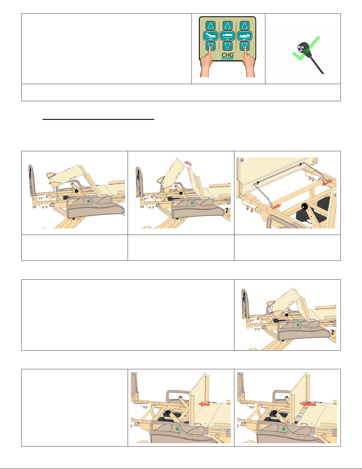
1-70-008 – H User Manual
- Spirit Plus 5600
CHG
Hospital
Beds
Page 69
of
103
successful completion of the “hard reset” procedure.
5.
Re-engage the deck sections by aligning the hinge
fingers and pressing the two deck sections together.
Refer to page 69 for instructions.
HINT: It may be helpful to have another person plug in the power supply cord while you
the HEAD DOWN and KNEE DOWN buttons.
PRESS and HOLD
4.3 Mattress Deck Removal
All four sections of the composite mattress deck can be detached for thorough cleaning, sanitization, and maintenance.
4.3.1 Mattress Deck Removal - Foot Section
1. Lift the foot and knee sections
together until the angle between
them is greater than 90º.
4.3.2 Accessing the CB10 Control Box
NOTE: If you are considering removing deck sections in attempts to
gain access to the CB10 control box, no deck sections need to be
removed from the bed.
2. Lift the foot section away from
the knee section at the hinge,
to separate the sections.
3. Disengage the foot bail from
the frame by flexing the two
ends together as shown.
From step 1 above, simply continue to rotate the foot section up until it
comes to rest against as shown right.
The CB10 control box is now accessible.
4.3.3 Mattress Deck Removal - Knee Section
Once the foot section is removed, the
knee section can be separated from
the stationary (bolted) seat section.
Lift the knee section until it is at an
angle of 90° to the seat section.
Using a horizontal force, strike the
knee section near the hinge to
separate these two sections.
Page 70
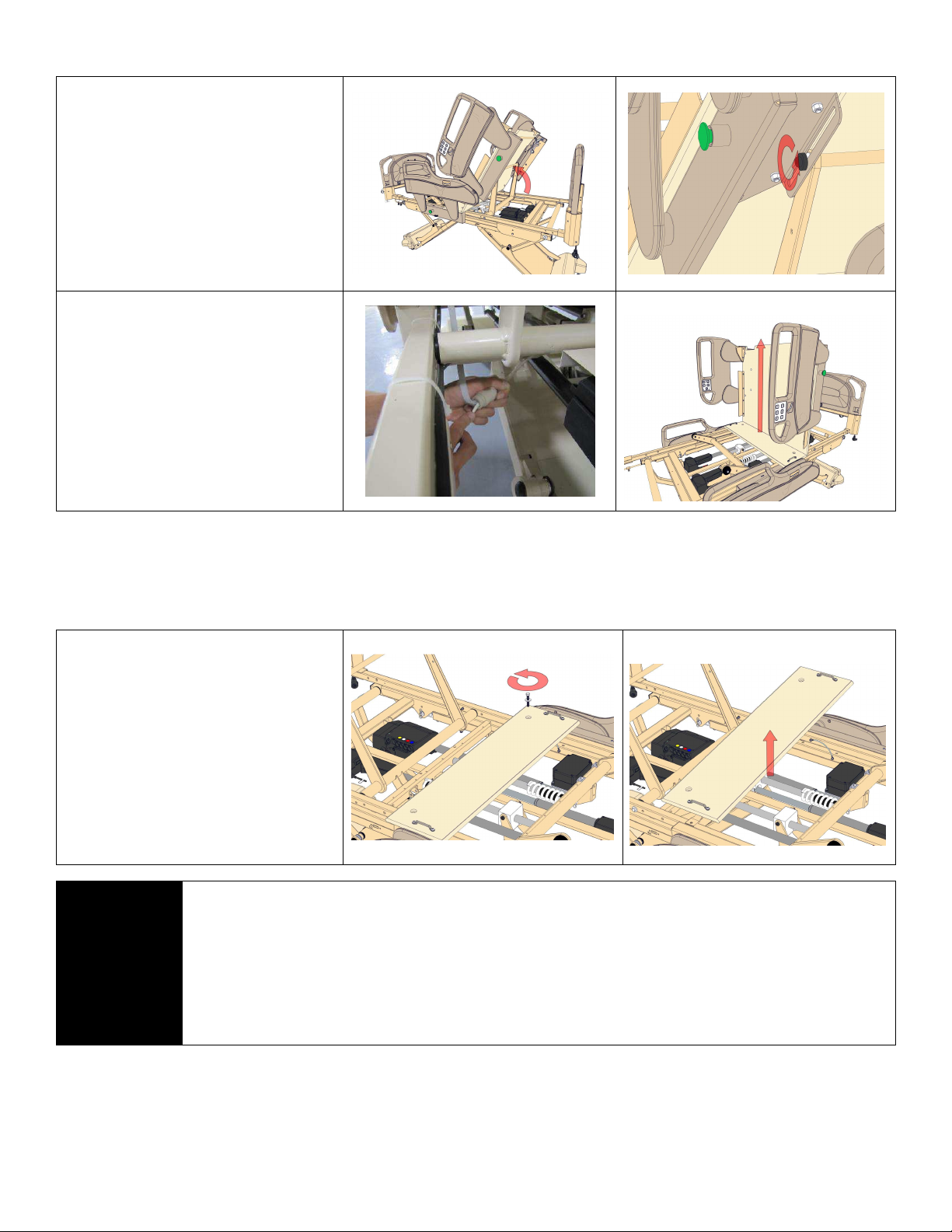
1-70-008 – H User Manual
- Spirit Plus 5600
CHG
Hospital
Beds
Page 70
of
103
4.3.4 Mattress Deck Removal - Head Section (Back Rest)
Elevate the head section (back
rest) to an angle of 55°.
Using a 3/16” Allen key, remove both
shoulder bolts fastening the head
deck (back rest) to the head gatch.
Locate both head siderail control
cables. Follow cables down to where
they are retained on the frame.
Using wire cutters, cut both zip ties.
Using a small, slot screw driver,
depress the retaining clip on both
head siderail control cables and
disconnect both cables.
The head section (back rest) can
now be lifted straight up, detaching
it from the stationary (bolted) seat
section.
4.3.5 Mattress Deck Removal - Seat Section
The seat section is attached to the bed frame with two bolts fasteners. Although it is not designed for routine
removal, it can be removed, if necessary.
Using a ratchet with a 1/2" SAE
socket loosen and remove the two
bolts fastening the seat section to
the bed frame.
The seat section can now be lifted
off the frame.
IMPORTANT: The head section
(back rest) must first be removed
before the seat section can be
removed from the bed.
NOTE:
Re-engage the deck sections by aligning the hinge fingers and pressing the two deck
sections together.
When reinstalling any section of the mattress deck, ensure that all hinges are
COMPLETELY engaged before attempting to articulate the connection.
Check for proper engagement by gently articulating the head, knee, and foot sections of the
mattress deck up and down. The head, knee, and foot sections of mattress deck should
articulate freely without binding.
Page 71
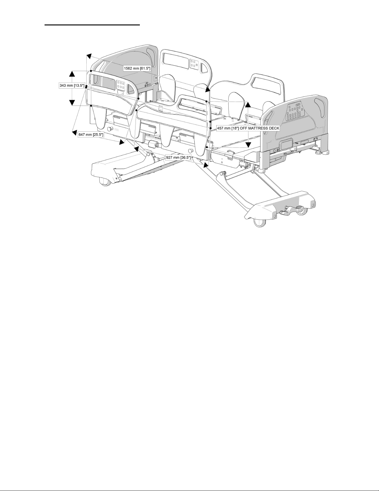
1-70-008 – H User Manual
- Spirit Plus 5600
CHG
Hospital
Beds
Page 71
of
103
4.4 Rail Measurements
Page 72
1-70-008 – H User Manual
- Spirit Plus 5600
CHG
Hospital
Beds
Page 72
of
103
4.5 Before Calling The Factory
To ensure prompt and accurate attention to your concerns please have the following information available
before you call:
Spirit™ Bed Service Call Information
Your facility’s phone number:
(Where you can be reached):
Your facility's fax number
(If Available)
:
Bed(s) Model and Type:
Bed(s) Serial Number
Date of Purchase:
List of defective part(s)
(
Identify by part number, or describe relative to
nearest numbered part)
:
List of deficiencies or Type of problem:
NOTE:
CHG Hospital Beds’ determination of the “Patient Left” and the “Patient Right” side of the
bed is made from the patient’s point of view while positioned normally on the bed facing up.
If you’re not 100% satisfied with your bed, please call your sales representative or technical service.
It's always better to ask if you have any questions such as hole drilling locations in head and footboards, or
before performing electrical service and/or modifications, or continuing to use a bed that has been damaged
and/or is exhibiting signs of minor damage. These activities could lead to more serious consequences such
as potential injury to patient and staff and/or equipment damage.
If you require further information regarding circuit diagrams, component part lists, descriptions etc. please
contact Stryker Medical Technical Service.
Call Stryker Medical Technical Service at Toll Free 1 (800) 327-0770 within the USA or 1 (800) 668-8323 within
Canada.
4.6 Colour Information
In the rare event that the painted finish on your Spirit™ bed becomes chipped you will require touch up
paint. CHG Hospital Beds recommends the use of Sherwin Williams Auto #5A-30041 – Gatsby Cream
(formerly #35-30041 – Cream)
Your Spirit™ bed may come with coloured inlay on the siderail
assemblies and/or on the footboard assembly. If these become
damaged and require replacement, please contact Stryker Medical
Technical Service to ensure that you receive matching inlays.
Page 73
1-70-008 – H User Manual
- Spirit Plus 5600
CHG
Hospital
Beds
Page 73
of
103
4.7 Troubleshooting Guide
Check to ensure that every connector is firmly connected to its respective header
Prior to using the Troubleshooting Guide, perform a brief function test on the bed. Check
NOTE:
Problem / Failure Recommended Action
all functions initiated from both the footboard staff control and the patient control
(staff/patient rail control and/or pendant) to determine which functions are not working.
Bed is connected (plugged
in) to an AC power outlet
but appears to be “frozen”
Power status indicators
may or may not be
illuminated/flashing
Bed is connected (plugged
in) to an AC power outlet
but bed is not functioning
Power status indicators
may or may not be
illuminated/flashing
Cycle the power on/off to reset the controls and re-establish proper communication
between the CB09 and CB10 control boxes.
1. Disconnect battery from CB10 control box
2. Disconnect (unplug) bed from the AC power outlet
3. After the bed has been disconnected from the AC power outlet, fully discharge
the CB09 control box by sequentially depressing the UP and DOWN buttons on
one of the siderail controls or on the pendant (depending upon how bed is
equipped) at least 20 times
4. Reconnect (plug in) the bed to the AC power outlet
5. Test any bed function from any control location to confirm proper bed control
has been restored
6. Reconnect battery to CB10 control box
7. Call for CHG Hospital Beds Customer Service for technical assistance
1. Check to ensure bed is connected (plugged in) to an AC power outlet
2. Check AC outlet for power
3. Check Master Lockout.
PRESS and HOLD
all three patient lock-out buttons at
same time to lock/unlock, then try bed functions
4. Lift head section of the mattress deck and remove dust shield from on top of
CB09 control box. Check for green power light (LED). If no light, check to
ensure that the power cord has been fully inserted into the inlet receptacle of
the CB09 control box
5. Check to ensure that the communication cable that runs between the CB09 and
CB10 control boxes is fully inserted into the port on the CB09 control box
6. Call for CHG Hospital Beds Customer Service for technical assistance
Some bed articulations no
longer working or are
intermittent regardless of
control location
Power status indicators
may or may not be
illuminated/flashing
If the head and/or foot sections of mattress deck no longer elevate/lower OR bed
will no longer raise/lower OR bed motion is intermittent it is necessary to ensure
proper connections.
1. Lift head section of the mattress deck and remove dust shield from on top of
CB09 control box
2. Check to ensure that every actuator colour coded cable has been fully inserted
into port on the CB09 with the corresponding colour code
3. Check to ensure that the power and the communication cable that run between
the CB09 and CB10 control boxes are fully inserted into their respective ports on
the CB09 control box
4. Lift foot section of the mattress deck and removed the cover from the CB10
control box
5.
on the CB10 circuit board
6. Test any bed function from any control location to confirm proper bed control
has been restored
7. Call for CHG Hospital Beds Customer Service for technical assistance
Page 74
1-70-008 – H User Manual
- Spirit Plus 5600
CHG
Hospital
Beds
Page 74
of
103
Patient controls working
on footboard.
Unplug rail connection at port and replace with pendant (if available). If pendant
out buttons on footboard.
ootboard.
properly, footboard staff
control not working
3. Check to ensure footboard is completely down into bracket
4. Check cable connection under lower left side of footboard
5. Check to make sure that there is no damage to Blindmate connectors (plastic
connector between bottom of footboard and footboard mounting bracket)
6. Check footboard staff control cable connection into CB10 control box under foot
section of mattress deck
7. Replace footboard control
Footboard staff control
working properly, rail
controls not working
Siderail control working on
one side of the bed only
Footboard staff control
working properly, pendant
not working
1. Some functions may be locked out. Check patient lock-out buttons
Patient lock-out prevents bed operation from rail controls
2. Check rail controls on both sides of bed. If only one rail control is not working
skip to next section. If both rail controls are not working, continue to next step
3. Check cable connections from rail to port on bed frame (ensure jack is fully
inserted into port)
4. Check pendant connection into CB10 control box under foot section of mattress
deck
5. Replace CB10 Control Box
1. Check cable connection (ensure connector is fully inserted into T-cable port)
2.
works, replace inoperable rail control. If pendant doesn’t work, replace T-Cable
1. Some functions may be locked out. Check patient lock-
Patient lock-out prevents bed operation from the pendant
2. Check cable connection from pendant to port on bed frame
3. Check pendant connection into CB10 control box under foot section of mattress
deck
4. Unplug pendant from current port and plug into port on opposite side of bed. If
pendant works in new port, replace T-Cable. If pendant does not work in new
port, continue to next step
5. Test pendant on a properly functioning bed (if available). If pendant works,
replace CB10 control box. If pendant doesn’t work, replace pendant
Only some functions
working on the rail controls
or pendant
Bed will not lower all the
way or the bed appears to
be a slight Trendelenburg
or reverse Trendelenburg
angle.
OR
The bed has ceased to
perform all
elevation/descent motion.
1. Some functions may be locked out. Check patient lock-out buttons on f
Amber LED on patient lock-out button prevents the bed operation from the rail
controls and pendant
2. Check cable connection from rail control to port on bed frame
3. Check pendant connection into CB10 control box under foot section of mattress
deck
4. Replace rail control or pendant
The Hi-Lo actuators are likely out-of-sync. The bed requires a “soft reset” to reestablish proper Hi-Lo actuator synchronization and/or restore proper bed operation.
1. Refer to page 68 for “soft reset” procedure.
Page 75

1-70-008 – H User Manual
- Spirit Plus 5600
CHG
Hospital
Beds
Page 75
of
103
Bed will not run on DC
power
1. Check to see if indicator LED on the Power Status Indicator is flashing RED. If
flashing, check to see if the battery has been disconnected from the CB10
control box. Connect DC plug into DC jack in the side of the CB10 control box
2. The battery is connected but voltage has dropped below 18VDC and the battery
has been automatically disconnected from battery circuit. Ensure bed is
connected (plugged in) to an AC power outlet and allow battery to recharge.
Confirm indicator LED is flashing GREEN and RED on the Power Status Indicator
3. If the service icon of the Power Status Indicator remains on after lengthy
recharge period, replace battery
4. If the service icon of the Power Status Indicator remains on after battery
replacement, replace CB10 control box
Bed Equipped With
Obstruction Sensing Option
Bed does not automatically
stop when one or more
obstructions sensors is
contacted
Bed Equipped With
Obstruction Sensing Option
Bed will not lower when
DOWN button pressed
Bed behaves like it is
contacting an obstruction
when none are obvious
1. Confirm which obstruction sensor(s) is(are) not working
2. Check to see if interconnection cables (between sensors) are connected or have
been twisted. Replace interconnection cables
3. Check to see if interconnection cables (between sensor and CB10 control box)
are connected or have been twisted. Replace interconnection cables.
4. Replace faulty obstruction sensor(s)
1. If no obstruction is present, carefully inspect each obstruction sensor for signs
of damage (gouge, dent, etc.). Damage could cause false switch contact to be
made. If no damage is obvious, continue to next step. If damage is obvious,
replace damaged obstruction sensor(s)
The obstruction sensors are linked in “series” to form an electrical circuit. The
circuit series is linked as follows: CB10 control box, interconnection cable, top leg
cover sensor, interconnection cable, caster cover sensor, interconnection cable,
bottom leg cover sensor
2. Disconnect interconnection cables (between sensors) to isolate the faulty
obstruction sensor(s). Begin by disconnecting one of the bottom leg cover
sensors from the circuit. Check Bed DOWN motion. If bed does not lower,
continue by disconnecting the other bottom leg cover sensor. Check Bed DOWN
motion. If bed does not lower, continue by disconnecting one caster cover
sensor from the circuit. Continue this process until the proper Bed DOWN
motion is achieved.
3. Reconnect obstruction sensor cables for functional obstruction sensors. Confirm
Bed DOWN motion is working.
4. Replace damaged obstruction sensor(s)
Page 76
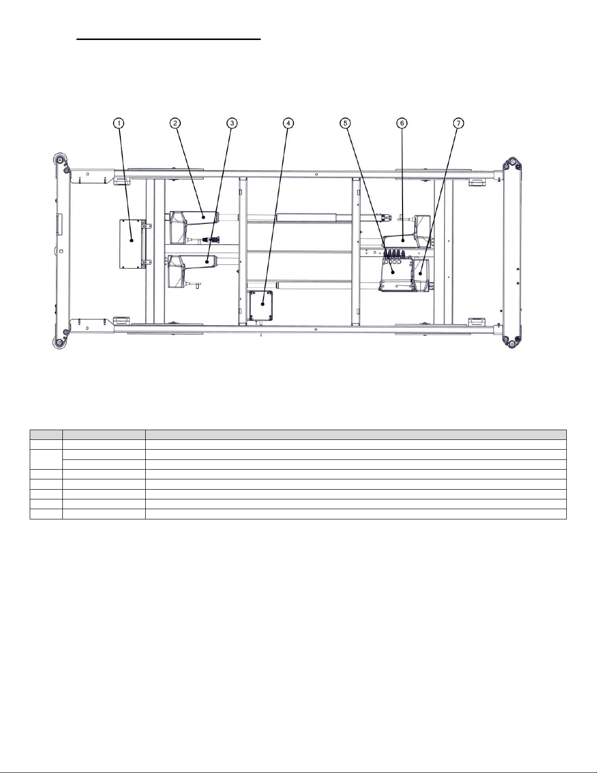
1-70-008 – H User Manual
- Spirit Plus 5600
CHG
Hospital
Beds
Page 76
of
103
4.8 Schematics & Technical
ITEM
KIT #
KIT DESCRIPTION
1 S0150
Service Kit, CB10 Lite (FOR USE WITH PLUS BEDS)
S0060
Service Kit,
Head Actuator, Low Rai
ls
SK0166 Service Kit, Head Actuator, High Rails
3 S0367
Service Kit, HI
-
LO Actuator Foot Mounted
4 S0379
Service Kit, 24VDC Battery Assembly (Plate Mount)
5 S0094
Service Kit, CB09, 120V
6 S0366
Service Kit, HI
-
LO Actuator Head Mounted
7 S0059
Serv
ice Kit, Foot Actuator
4.8.1 Spirit Wiring Schematic
2
Page 77
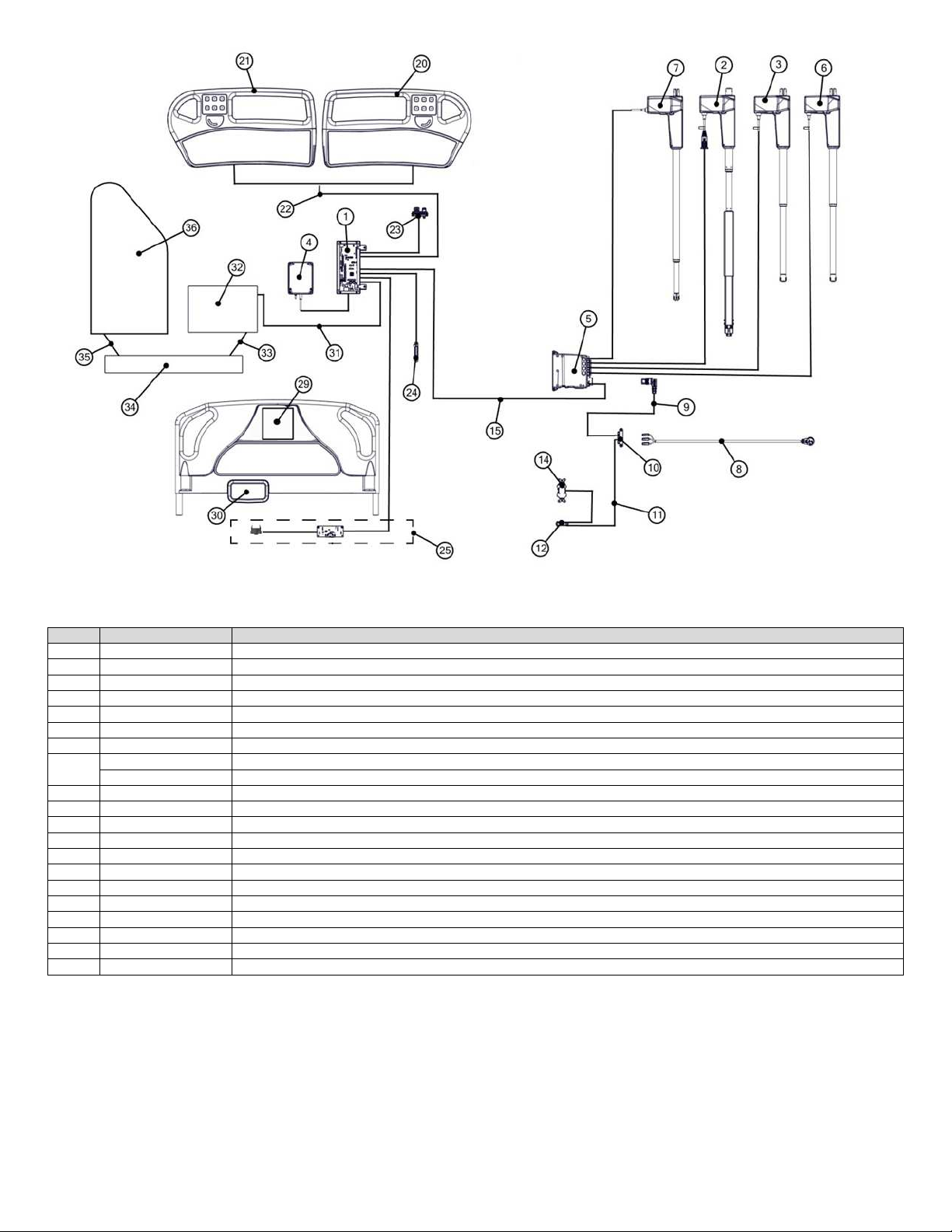
1-70-008 – H User Manual
- Spirit Plus 5600
CHG
Hospital
Beds
Page 77
of
103
ITEM
KIT #
KIT DESCRIPTION
1-7
SEE ELECTRICAL COMPONENTS
8 SK0133 Service Kit, Mains AC Supply Cable
9 S0134
Service Kit, Internal Mains AC Supply Cable
10 SK0132 Service Kit, Mains AC Terminal
Block
11 S0135
Service Kit, Auxiliary Outlet Mains Cable
12 SK0137 Service Kit, Thermal Circuit Breaker, 5 AMP
14 SK0136 Service Kit, Hospital Grade Duplex Receptacle
SK0139 Service Kit, CB09 to CB10 Communication Cable
SK0140 Service Kit, CB09 to
CB10 Power Cable
20/21
SEE RAIL PANEL COMPONENTS
22 SK0141 Service Kit, T
-
Cable, Siderail Controls
23 SK0138 Service Kit, Patient Station Cable
24 S0131
Service Kit, Underbed Light
25 SK0502
Service Kit, Blindmate Harness Assembly (4P)
29/30
SEE F
OOTBOARD COMPOENTS
31 SK0129 Service Kit, Obstruction Sensor CB10 Cable
32 S0314
Service Kit, Top Leg Obstruction Sensor
33 SK0128 Service Kit, Obstruction Sensor Link Cable (4 PIN)
34 S0311
Service Kit, Caster Cover Obstruction Sensor
35 S0380
Servic
e Kit, Obstruction Sensor Link Cable (6 PIN)
36 S0193
Service Kit, Bottom Leg Obstruction Sensor
15
Page 78
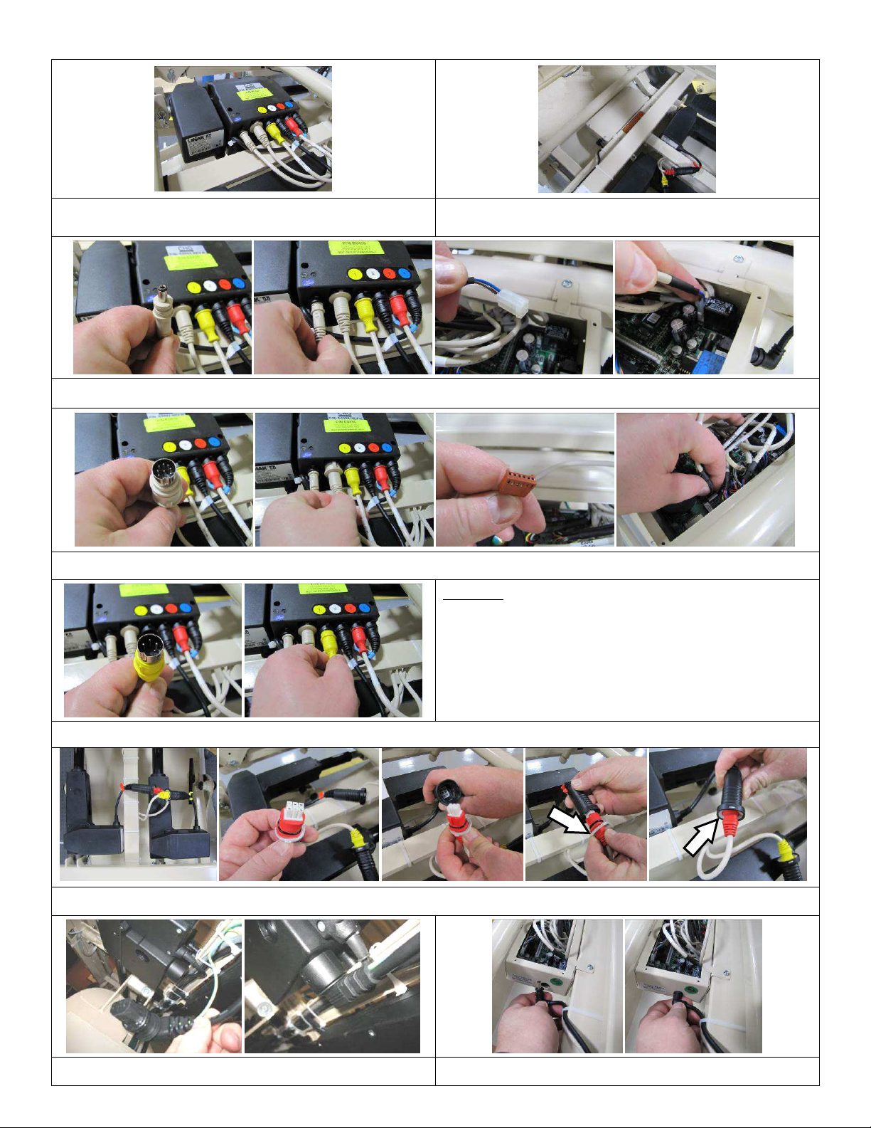
1-70-008 – H User Manual
- Spirit Plus 5600
CHG
Hospital
Beds
Page 78
of
103
4.8.2 Electrical Connections – Overview
CB09 Control Box
CB09 is common to all Spirit™ beds
IMPORTANT: CB09 Control boxes are NOT interchangeable!
DC Power Cable (Ø5.5 mm X Ø2.5 mm male plug end)
Provides 24VDC power from CB09 control box to DC power input header on CB10 control box
Communication Cable (8 pin, DIN style, double keyed connector)
Carries communication between CB09 control box and COMM header on CB10 control box
CB10 Control Box
CB10Lite control box – Spirit Plus™
Colour Code
Yellow: Hi-Lo Actuator (Mounted at Foot End of Bed)
White (tape): Hi-Lo Actuator Extension Cable (Mounted at Head End of Bed)
Red: Head Actuator Extension Cable
Actuator Cable Plug (4 pin, DIN style, double keyed connector)
Hi-Lo Actuators are common for all Spirit™ beds. Head/Knee actuators are unique for each Spirit™ depending upon configuration
Foot Mounted Actuator Extension Cables (4 pin, DIN style, double keyed connector to 6 pin modular connector)
Connects foot mounted actuator cables to CB09 control box. Retainer requires small slot screwdriver to remove (arrow)
Blue (tape): Knee Actuator
CB09 Control Box Power Supply Cable (IEC 320 C13 female plug end)
Typical on all beds
Battery Connection Cable (Ø5.5 mm X Ø2.5 mm male plug end)
Typical on all beds
Page 79
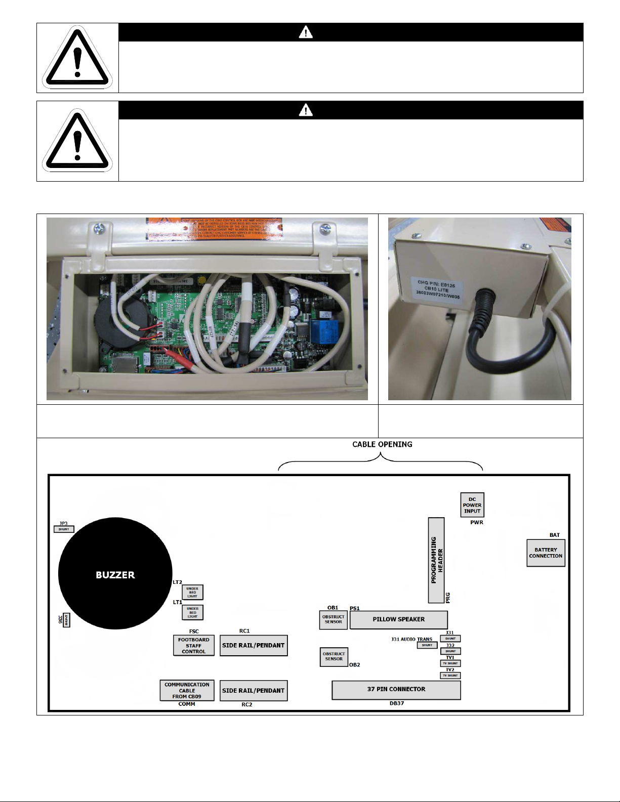
1-70-008 – H User Manual
- Spirit Plus 5600
CHG
Hospital
Beds
Page 79
of
103
WARNING
CB1
0Lite cable connections shown: communication cable (p/n E0064), power cable
ALWAYS ensure that bed is disconnected (unplugged) from mains AC power (wall outlet) before
disconnecting/connecting any cable from/to either the CB10 or CB09 control boxes. Failure to do
so may result in damage or degradation of control box circuit board components.
WARNING
Some versions of CB09 control boxes are NOT interchangeable.
If you have to replace your CB09 control box call Stryker Medical Technical Service to
ensure that you have the correct version of this component at toll free 1-800-327-0770
(USA) or 1-800-668-8323 (Canada).
4.8.3 Spirit Plus™ CB10Lite Control Box – Overview
(p/n E0067), footboard staff control cable (E0151), siderail t-cable (E0060), and
patient station cable (E0078)
CB10Lite serial number label (affixed to
enclosure next to battery connection)
Page 80
1-70-008 – H User Manual
- Spirit Plus 5600
CHG
Hospital
Beds
Page 80
of
103
4.9 Electromagnetic Compatibility (EMC)
The Spirit Select hospital bed needs special precautions regarding EMC and needs to be installed and put
into service according to the EMC information provided in this manual. Portable and mobile RF
communications equipment can affect the Spirit Select Bed.
WARNING
This Spirit Select Hospital Bed is intended for use by healthcare professionals only. This
equipment/system may cause radio interference or may disrupt the operation of nearby
equipment. It may be necessary to take mitigation measures, such as reorienting or
relocating the equipment or shielding the location.
The following list of cables and accessories are in compliance with the Medical Electrical Equipment
requirements:
PART
No.
A5001 37 PIN GENDER CHANGER (FEMALE TO MALE)
A5003 NURSE CALL CABLE, 1/4" TO 1/4" MONO, STD WIRING
A5004 NURSE CALL CABLE, 37 PIN TO 37 PIN, STD WIRING, 8'
A5005 NURSE CALL CABLE, 37 PIN TO 1/4" PHONO, INTERLOCK
A5006 NURSE CALL CABLE, 1/4" PHONO TO 18 PIN (PROCARE)
A5007 NURSE CALL CABLE, 37 PIN TO 18 PIN (DUKANE)
A5009 NURSE CALL CABLE, 37 PIN TO 1/4" W/ 1/4" JACK
A5010 NURSE CALL CABLE, 37 PIN TO 7 PIN (EXECUTONE)
A5011 NURSE CALL CABLE, 37 PIN TO 18 PIN (DUKANE)
A5013 NURSE CALL CABLE, 37 PIN TO 1/4" PHONO (EXECUTONE)
A5014 NURSE CALL CABLE, 1/4" PHONE JACK FOR NURSE CALL
A5015 NURSE CALL CABLE, 1/4" PHONO JACK FOR BED EXIT
A5016 NURSE CALL CABLE, RAULAND RESPONDER 3
A5017 NURSE CALL CABLE, RAULAND RESPONDER 4 (AND JERON)
A5019 NURSE CALL CABLE, 37 PIN TO 37 PIN, 90° PLUG
A5020 NURSE CALL CABLE, 37 PIN TO 1/4" PHONO, NO INTRLCK
A5021 NURSE CALL CABLE, 37 PIN TO 37 PIN ADAPTER BOX
A5022 NURSE CALL CABLE, 37 PIN TO 18 PIN (JERON 1801)
A5024 NURSE CALL CABLE, 37 PIN TO 37 PIN ADAPTER
A5025 NURSE CALL CABLE, 37 PIN MALE TO 37 PIN FEMALE
A5026 NURSE CALL CABLE, 37 PIN-37 PIN, STD WIRING, 12'
A5028 NURSE CALL CABLE, 1/4"M-1/4"F 6" JUMPER W/ CORDOUT
A5030 NURSE CALL CABLE, RESPONDER 4000 ADAPTER BOX
A5031 NURSE CALL Y CABLE, 37 PIN TO 1/4" NC & PRIORITY
A5032 NURSE CALL CABLE, P909-P3701 ZETLLER SENTINAL 500
A5036 NURSE CALL CABLE, 417 P37R, DU, 1L, 2LD, INLK, TLK
A5037 NURSE CALL CABLE, 419 P37, DU, BE, TLK
A5039 BREAKAWAY CABLE, P37 - P37 DP 10&11 7&25
A5040 CALLCORD ASSEMBLY, 96", GRAY, 1/4", CURBELL LOGO
A5041 NURSE CALL CABLE, 800 P37, TT, BE, 2L, INLK, RLY
A5042 NURSE CALL CABLE, 800 P37R, JE, BE, 1L
A5044 ADAPTOR, 1, P1802, S1802, 1/4", N, FLANGE
A5050 NURSE CALL CABLE, 1801, 103, P37, GE, BE, 2L, 2LD
A5051 NURSE CALL CABLE, 800 P37R, J3, 1L, INLK, TLK
A5054 NURSE CALL CABLE, 1010, 102 P37, WESTCALL
A5055 NURSE CALL CABLE, 800 S37, AU, NO, TV, NO, TLK
A5065 JUMPER, 96" LONG, 1/4" 90° TO 1/4" INLINE
A5068 NURSE CALL CABLE, 1505 P37, FB, BE, 2L
A5069 ADAPTER, 1 X P800 TO 2 X S800, 1/4" NC,TEKTONE
DESCRIPTION
Page 81
1-70-008 – H User Manual
- Spirit Plus 5600
CHG
Hospital
Beds
Page 81
of
103
A5071 NURSE CALL CABLE, DB37 TO RAULAND 800
A5072 NURSE CALL CABLE, RAULAND 800 TO DB37
A5074 NURSE CALL CABLE, 37 PIN TO 8 PIN
A5077 NURSE CALL CABLE, P37 TO 20PIN (P320) & 1/4" (8')
A5080 BREAKAWAY CABLE, 37 PIN TO RAULAND RESPONDER 4
WARNING
The use of accessories and cables other than those specified, with the exception of
accessories and cables qualified and sold by the manufacturer of the equipment may result
in increased emissions or decreased immunity of the equipment and may cause the system
to be non-compliant with the requirements of IEC 60601-1-2:2007
WARNING
The equipment should not be used adjacent to or stacked with other equipment and that if
adjacent or stacked use is necessary, the equipment should be observed to verify normal
operation in the configuration in which it will be used.
EMC Tables
IEC 60601-1-2:2007 Table 1 Requirements
The equipment is intended for use in the electromagnetic environment specified below. The customer or the user of the
equipment should assure that it is used in such an environment.
Emissions test Compliance Electromagnetic environment – guidance
The equipment uses RF energy only for its internal function. Therefore, its
RF emissions CISPR
11
Group 1
RF emissions are very low and are not likely to cause any interference in
nearby electronic equipment.
RF emissions
CISPR 11 Class A
Harmonic emissions
IEC 61000-3-2
Class A
The equipment is suitable for use in all establishments other than domestic,
and may be used in domestic establishments and those directly connected
to the public low-voltage power supply network that supplies buildings used
for domestic purposes, provided the following warning is heeded: Warning:
This equipment/system is intended for use by healthcare professionals
only. This equipment/ system may cause radio interference or may disrupt
Voltage fluctuations/
flicker emissions
Complies
the operation of nearby equipment. It may be necessary to take mitigation
measures, such as re-orienting or relocating the equipment or shielding the
IEC 61000-3-3
location.
Page 82
1-70-008 – H User Manual
- Spirit Plus 5600
CHG
Hospital
Beds
Page 82
of
103
IEC 60601-1-2:2007 Table 2 Requirements:
The equipment is intended for use in the electromagnetic environment specified below. The customer or the user of the
Equipment should assure that it is used in such an environment.
Immunity test
Electrostatic
discharge (ESD)
IEC 61000-4-2
Electrical fast
transient/burst IEC
61000-4-4
Surge IEC 61000-
4-5
IEC 60601 test
level
±6 kV contact
±8 kV air
±2 kV for power
supply lines ±1 kV
for input/output
lines
±1 kV line(s) to
line(s) ±2 kV line(s)
to earth
Compliance level Electromagnetic environment – guidance
±6 kV contact
±8 kV air
±2 kV for power
supply lines ±1 kV for
input/output lines
±1 kV line(s) to line(s)
±2 kV line(s) to earth
Floors should be wood, concrete or ceramic tile. If
floors are covered with synthetic material, the
relative humidity should be at least 30 %.
Mains power quality should be that of a typical
commercial or hospital environment.
Mains power quality should be that of a typical
commercial or hospital environment.
Voltage dips, short
interruptions and
voltage variations
on power supply
input lines IEC
61000-4-11
UT = 230 Vac
Power frequency
(50 Hz) magnetic
field
IEC 61000-4-8
<5 % UT (>95 %
dip in UT) for 0,5
cycle 40 % UT (60
% dip in UT) for 5
cycles 70 % UT
(30 % dip in UT)
for 25 cycles
<5 % UT (>95 %
dip in UT) for 5 sec
3 A/m 3 A/m
<5 % UT (>95 % dip
in UT) for 0,5 cycle
40 % UT (60 % dip in
UT) for 5 cycles 70 %
UT (30 % dip in UT)
for 25 cycles
<5 % UT (>95 % dip
in UT) for 5 sec
Mains power quality should be that of a typical
commercial or hospital environment. If the user of
the equipment requires continued operation during
power mains interruptions, it is recommended that
the equipment be powered from an uninterruptible
power supply or a battery.
Power frequency magnetic fields should be at levels
characteristic of a typical location in a typical
commercial or hospital environment.
Page 83
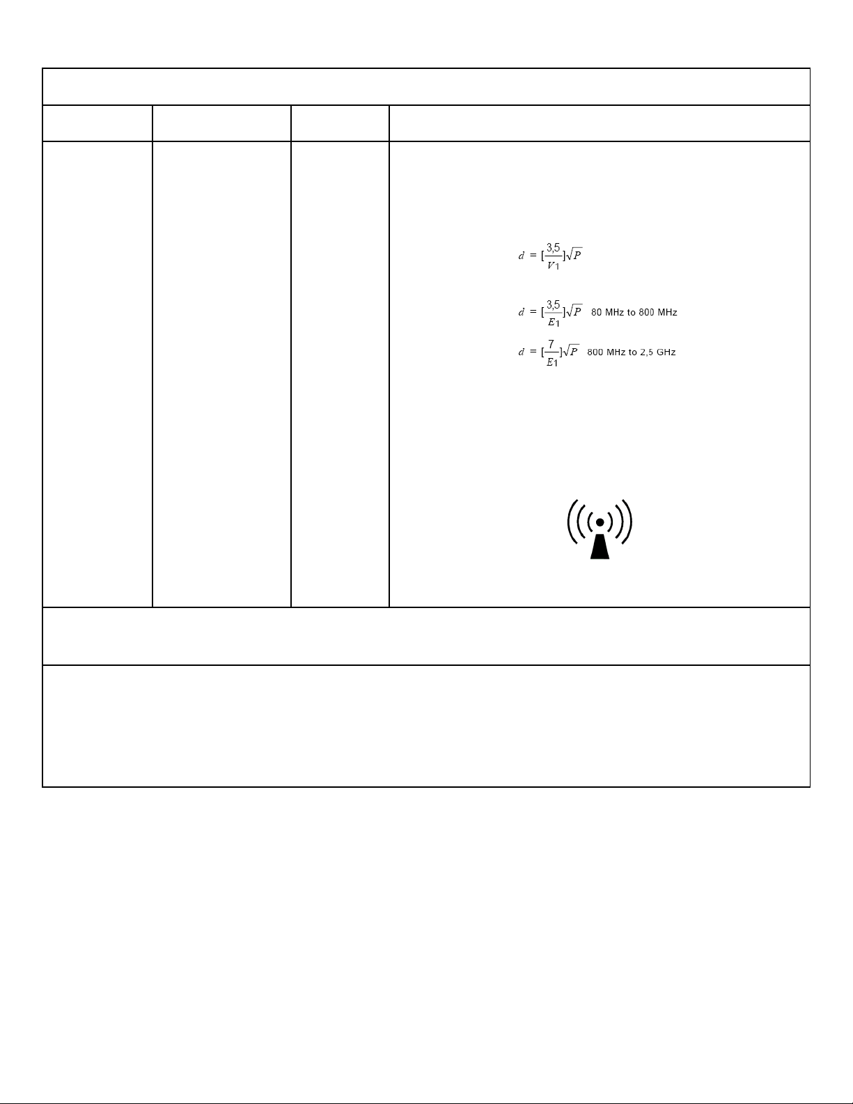
1-70-008 – H User Manual
- Spirit Plus 5600
CHG
Hospital
Beds
Page 83
of
103
IEC 60601-1-2:2007 Table 4 Requirements:
The equipment is intended for use in the electromagnetic environment specified below. The customer or the user of the
equipment should assure that it is used in such an environment.
Immunity test
Conducted RF
IEC 61000-4-6
Radiated RF
IEC 61000-4-3
IEC 60601 test
level
3 Vrms
150 kHz to 80 MHz
3 V/m 80 MHz to
2,5 GHz
Compliance
level
3 V
3 V/m
Electromagnetic environment – guidance
Portable and mobile RF communications equipment should be used no closer to
any part of the equipment including cables, than the recommended separation
distance calculated from the equation applicable to the frequency of the
transmitter.
Recommended separation distance
where P is the maximum output power rating of the transmitter in watts (W)
according to the transmitter manufacturer and d is the recommended separation
distance in meters (m). Field strengths from fixed RF transmitters, as determined
by an electromagnetic site surveya should be less than the compliance level in
each frequency rangeb
Interference may occur in the vicinity of known RF transmitting devices and
equipment marked with the following symbol:
NOTE 1 At 80 MHz and 800 MHz, the higher frequency range applies.
NOTE 2 These guidelines may not apply in all situations. Electromagnetic propagation is affected by absorption and reflection from structures, objects
and people.
a) Field strengths from fixed transmitters, such as base stations for radio (cellular/cordless) telephones and land mobile radios, amateur radio, AM and
FM radio broadcast and TV broadcast cannot be predicted theoretically with accuracy. To assess the electromagnetic environment due to fixed RF
transmitters, an electromagnetic site survey should be considered. If the measured field strength in the location in which the equipment is used exceeds
the applicable RF compliance level above, the equipment should be observed to verify normal operation. If abnormal performance is observed,
additional measures may be necessary, such as re-orienting or relocating the equipment
b) Over the frequency range 150 kHz to 80 MHz, field strengths should be less than 3 V/m.
Page 84
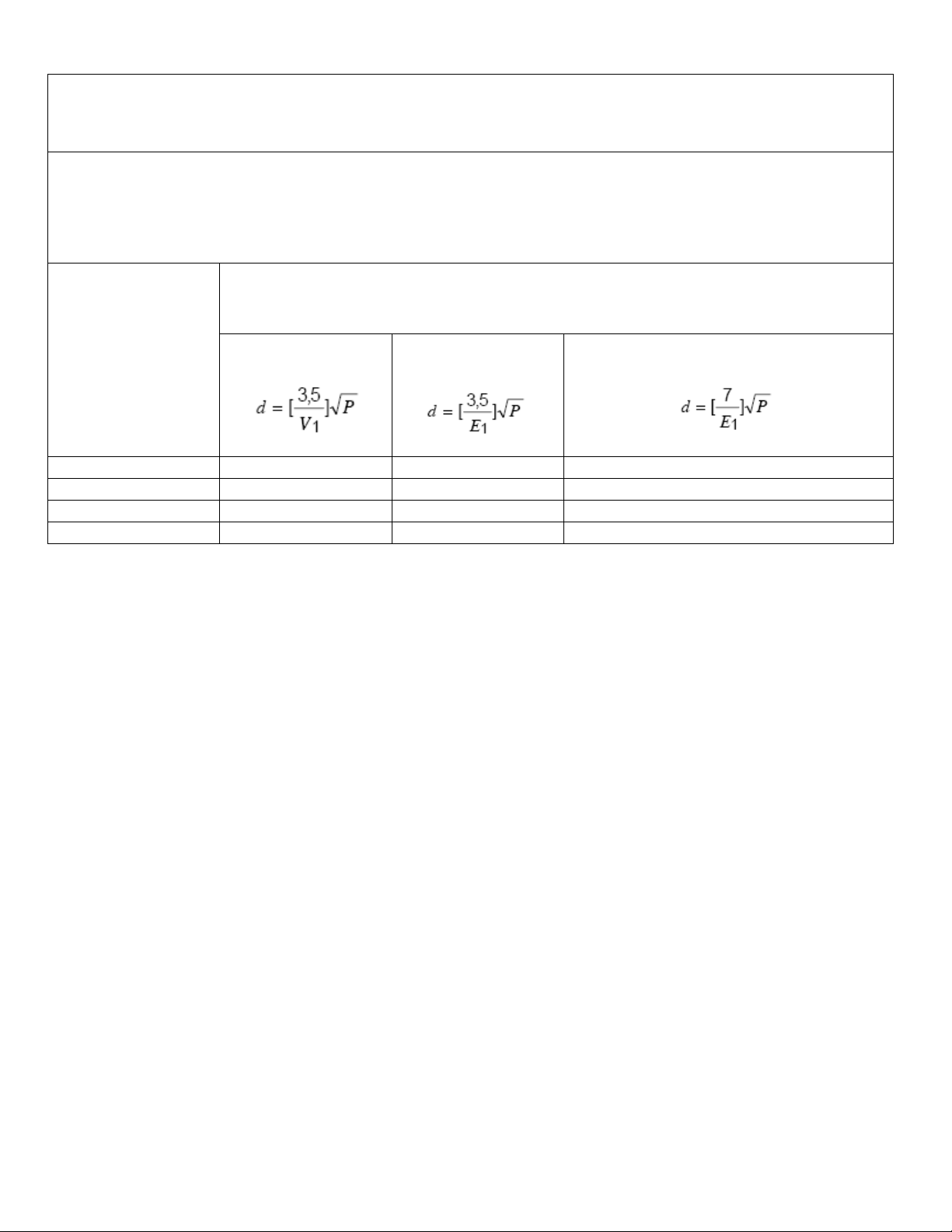
1-70-008 – H User Manual
- Spirit Plus 5600
CHG
Hospital
Beds
Page 84
of
103
IEC 60601-1-2:2007 Table 6 Requirements:
0.01 0.12 0.12 0.24
0.1 0.37 0.37 0.74
1 1.17 1.17 2.34
10 3.69 3.69 7.38
Recommended separation distances between
portable and mobile RF communications equipment and the [
ME EQUIPMENT
The [
ME EQUIPMENT
disturbances are controlled. The customer or the user of the [
electromagnetic interference by maintaining a minimum distance between portable and mobile RF communications
equipment (transmitters) and the [
output power of the communications equipment.
or
ME SYSTEM
] is intended for use in an electromagnetic environment in which radiated RF
ME EQUIPMENT
or
ME SYSTEM
ME EQUIPMENT
] as recommended below, according to the maximum
or
ME SYSTEM
] can help prevent
or
ME SYSTEM
]
Rated maximum output
power
of transmitter
W
150 kHz to 80 MHz
Separation distance according to frequency of transmitter
M
80 MHz to 800 MHz
800 MHz to 2.5 GHz
Page 85
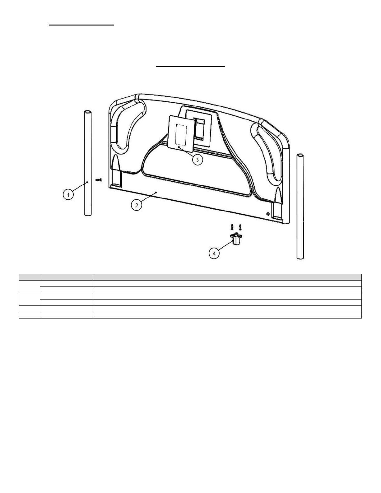
1-70-008 – H User Manual
- Spirit Plus 5600
CHG
Hospital
Beds
Page 85
of
103
4.10 Service Parts
ITEM
KIT #
KIT DESCRIPTION
S0384
Service Kit, Footboard Post
S0323
Service Kit, Psych Footboard Post
SK0493
Service Kit, Plus Footboard Complete
S0396
Serv
ice Kit, Plus Footboard Complete Psych
3 S0044
Service Kit, Plus Footboard Staf
f Control
4 SK0502
Servic
e Kit, Blindmate Harness Assembly (4P)
NOTE: Service parts shown reflect current production Spirit™ beds. If you are servicing an older Spirit™ bed, or if you have any doubts/concerns,
please contact Stryker Medical Technical Service at toll free 1-800-327-0770 (USA) or 1-800-668-8323 (Canada) to ensure that you receive the correct
parts.
PLUS FOOTBOARD
1
2
Page 86
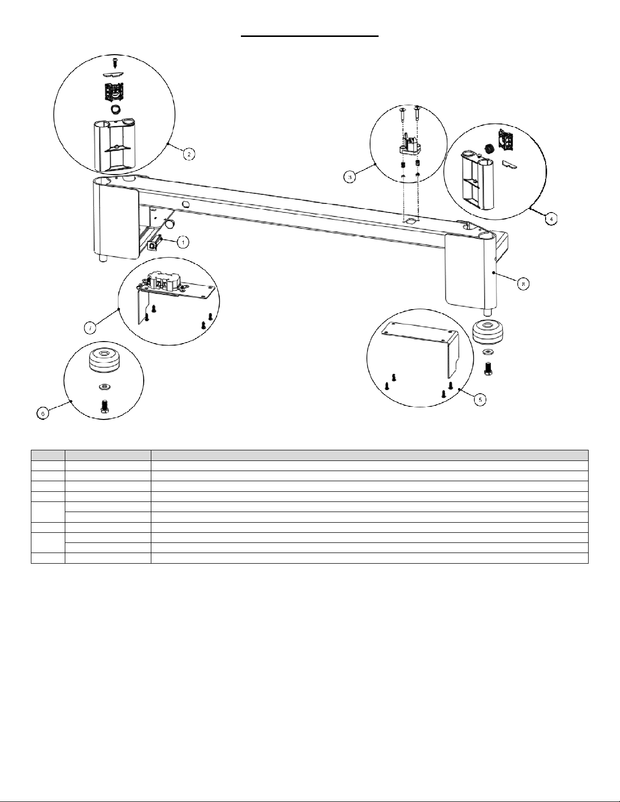
1-70-008 – H User Manual
- Spirit Plus 5600
CHG
Hospital
Beds
Page 86
of
103
FOOTBOARD BRACKET
ITEM
KIT #
KIT DESCRIPTION
1 SK0137 Service Kit, Thermal Circuit Breaker,
5 Amp
2 SK0117 Service Kit, Footboard Bracket Insert PR
3 SK0501 Service Kit,
Plus Footboard Bracket Cable (4P)
4 SK0118 Service Kit, Footboard Bracket Insert PL
SK0504
Service Kit, PL Footboard Bracket Cover
S0404
Service Kit, WD Bypass Intermedi
ate Board and Cover
6 S0027
Service Kit, Footboard Bracket Corner Bumper
S0400
Service Kit, Auxiliary Outlet and Cover (120V)
S0402
Service Kit, PR Footboard Bracket Cover
8 SK
0505 Service Kit,
Footboard Bracket (4P)
5
7
Page 87
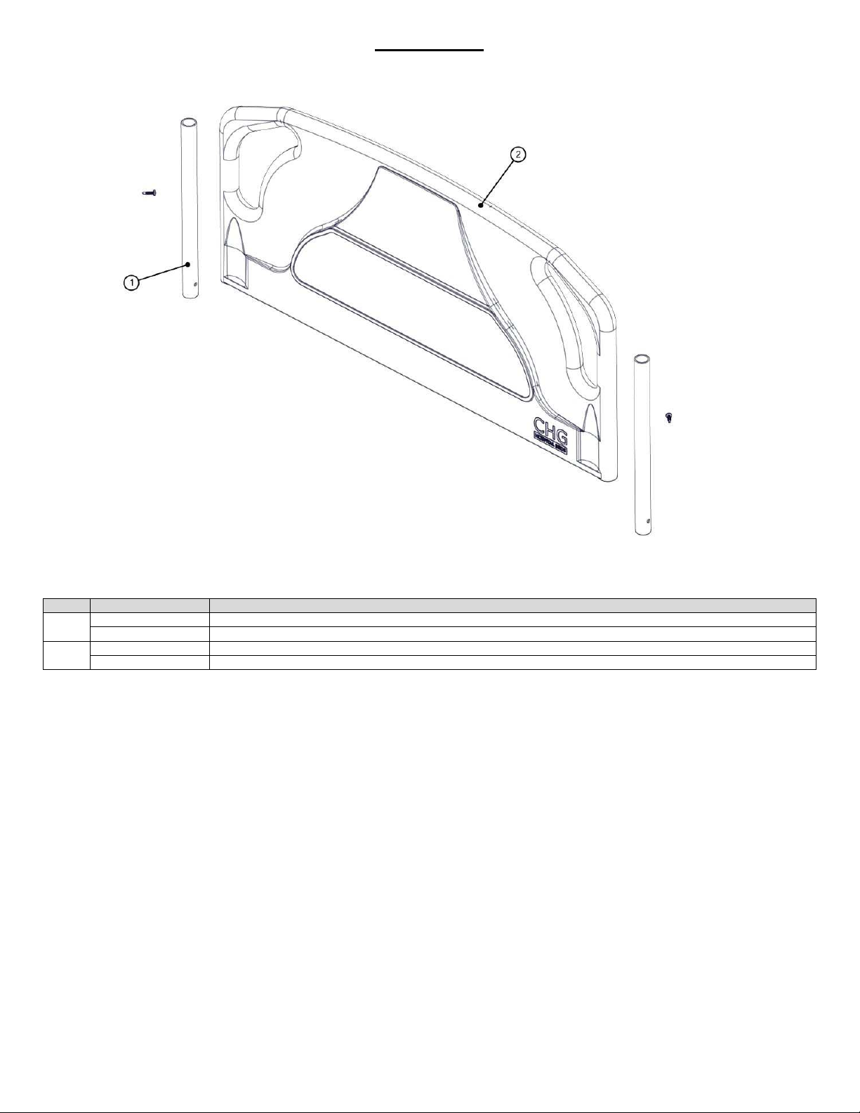
1-70-008 – H User Manual
- Spirit Plus 5600
CHG
Hospital
Beds
Page 87
of
103
HEADBOARD
ITEM
KIT #
KIT DESCRIPTION
S0384
Service Kit, Footboard Post
S0383
Service Kit, Psych Footboard Post
SK0113 Service Kit, Headboard
Complete
S0188
Service Kit, Psych Headboard
Complete
1
2
Page 88
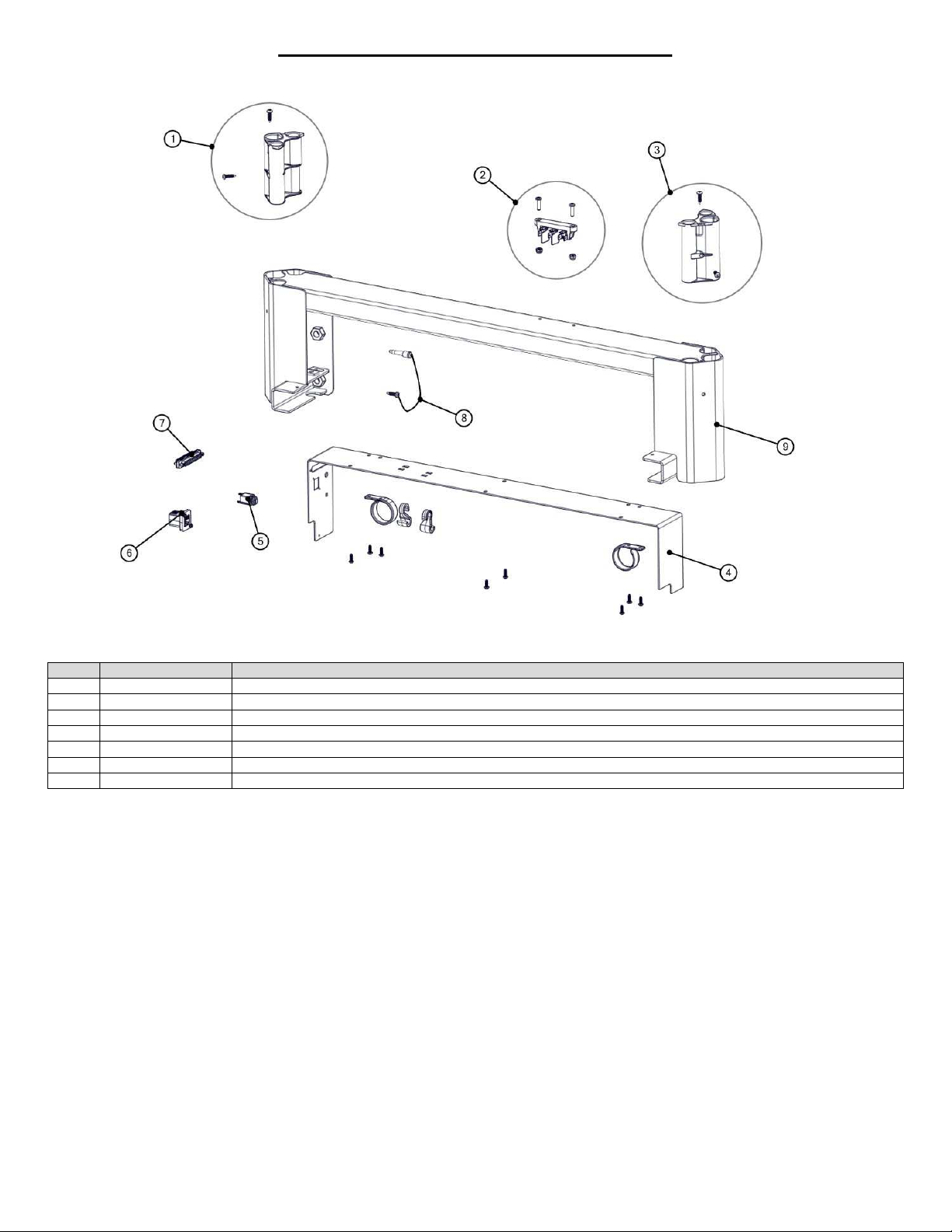
1-70-008 – H User Manual
- Spirit Plus 5600
CHG
Hospital
Beds
Page 88
of
103
HEADBOARD BRACKET (HIGH RAIL BEDS)
ITEM
KIT #
KIT DESCRIPTION
1 SK0115 Service Kit, Headboard Bracket Insert PR
2 SK0132 Service Kit, Mains AC Terminal Block
3 SK0116 Service Kit, Headboard Bracket Insert PL
4 S0406
Service Kit, High Headboard Bracket Cover
7 SK0138 Service Kit, Patient Station Cable
8 S0011
Servic
e Kit, ¼” Dummy Plug
9 S0411
Service Kit, High Headboard Bracket Complete
Page 89
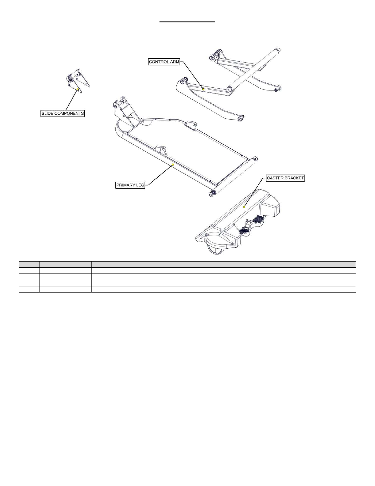
1-70-008 – H User Manual
- Spirit Plus 5600
CHG
Hospital
Beds
Page 89
of
103
LEG ASSEMBLY
ITEM
KIT #
KIT DESCRIPTION
1
SEE SLIDE COMPONENTS
2
SEE CONTROL ARM
3
SEE CASTER BRACKET
4
SEE PRIMARY LEG
Page 90
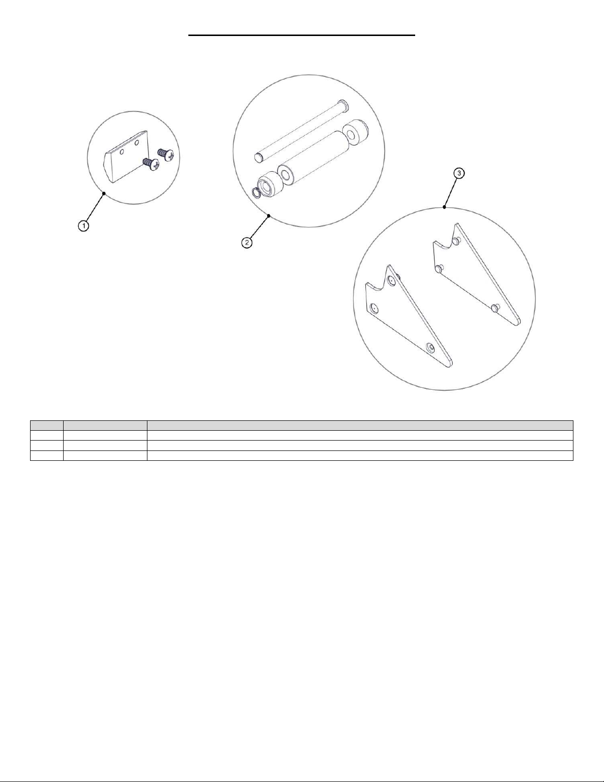
1-70-008 – H User Manual
- Spirit Plus 5600
CHG
Hospital
Beds
Page 90
of
103
LEG ASSEMBLY - SLIDE COMPONENTS
ITEM
KIT #
KIT DESCRIPTION
1 S0414
Service Kit, Push Block Hi/Lo Spring
2 S0415
Service Kit, Leg Roller Assembly
3 S0416
Service Kit, Leg Bracket Wear Pads
Page 91
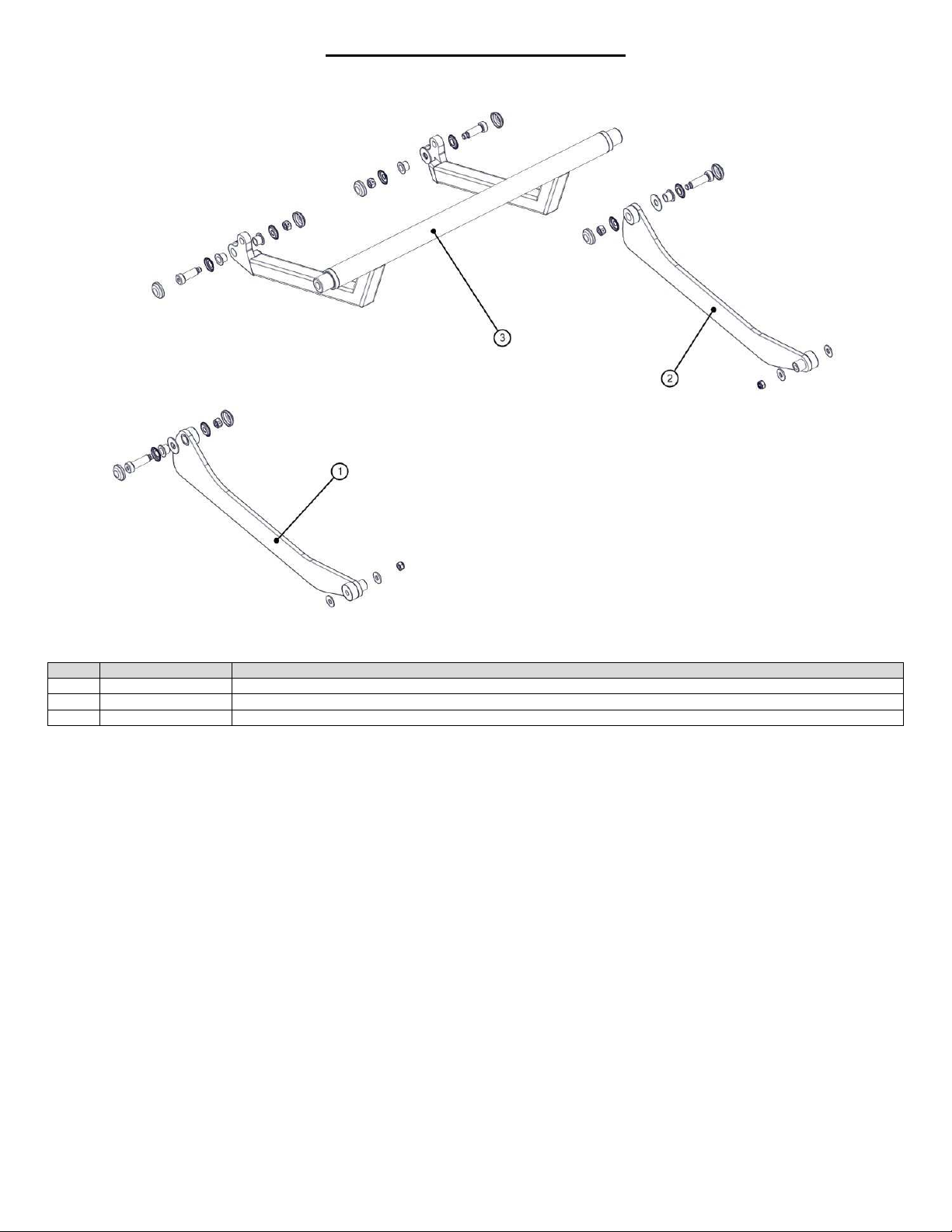
1-70-008 – H User Manual
- Spirit Plus 5600
CHG
Hospital
Beds
Page 91
of
103
LEG ASSEMBLY - CONTROL ARM
ITEM
KIT #
KIT DESCRIPTION
1 SK0429 Service Kit, Suspension Arm
A
(N2/N3)
2 S0430
Service Kit, Suspension Arm B
(N2/N3)
3 S0417
Service Kit, Control Arm
Page 92
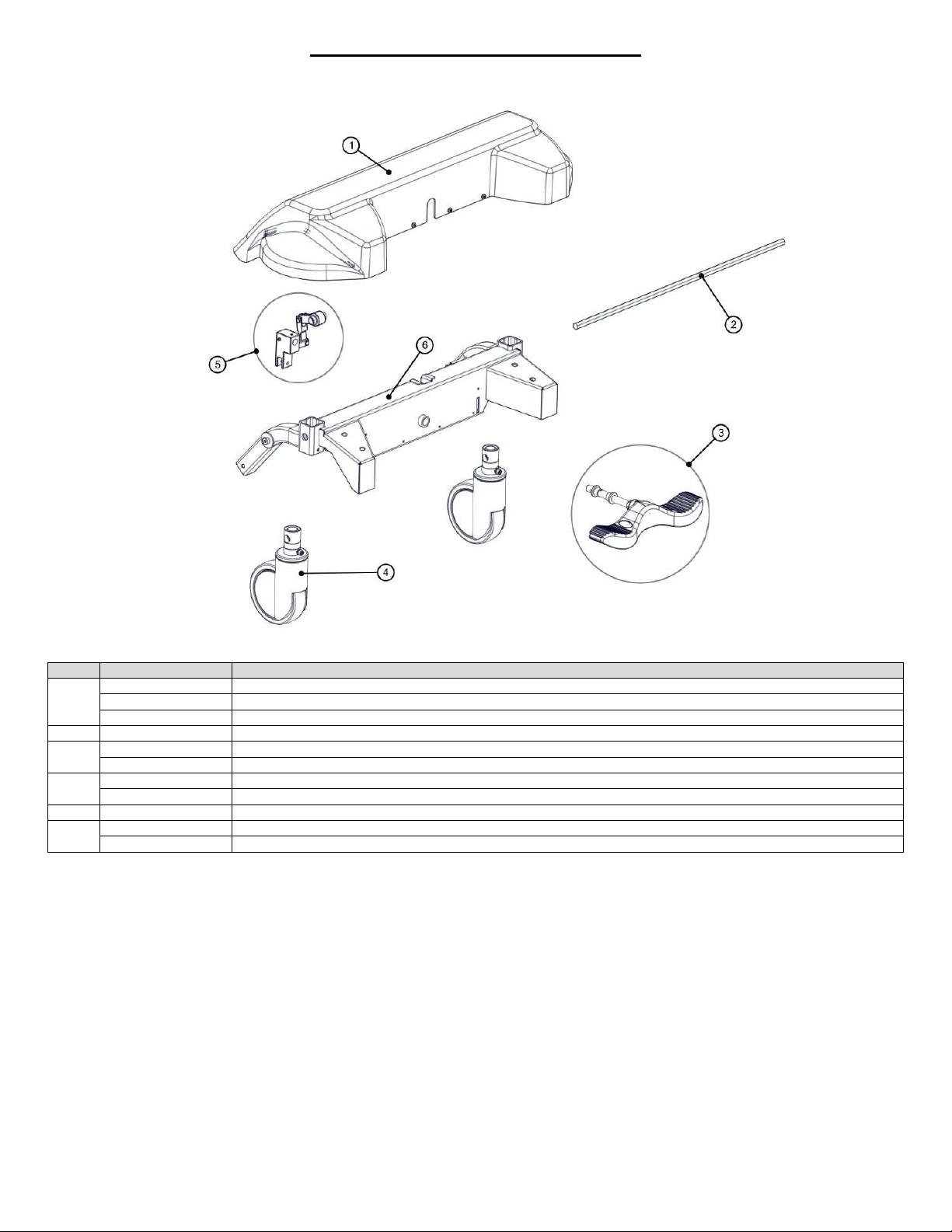
1-70-008 – H User Manual
- Spirit Plus 5600
CHG
Hospital
Beds
Page 92
of
103
LEG ASSEMBLY – CASTER BRACKET
ITEM
KIT #
KIT DESCRIPTION
S0077
Service Kit, ABS Caster Cover
S0161
Service Kit, ABS Caster Cover + OBS
S0311
Service
Kit, Caster Cover Obstruction Sensor
2 S0022
Service Kit, Caster Hex Rod
SK0121 Service Kit, Brake Pedal Assembly (Head End)
SK0122 Service Kit, Brake Pedal Assembly (Foot End)
S0064
Service Kit, Head End Caster (Red Label)
S0065
Service Kit, F
oot End Caster (Green Label)
5 S0224
Service Kit, Complete Brake Pedal Linkage
S0103
Service Kit, Caster Assembly, Head, Complete
S0104
Service Kit, Caster Assembly, Foot, Complete
1
3
4
6
Page 93
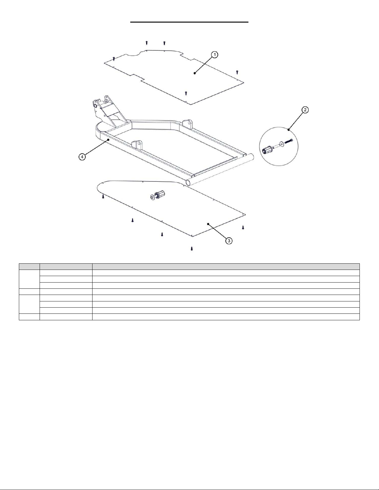
1-70-008 – H User Manual
- Spirit Plus 5600
CHG
Hospital
Beds
Page 93
of
103
LEG ASSEMBLY – PRIMARY LEG
ITEM
KIT #
KIT DESCRIPTION
S0232
Service Kit, Top Leg Cover
S0230
Service Kit, Top Leg Cover + OBS
S0314
Service Kit, Top Leg Obstruction Sensor
2 S0239
Service Kit, Gatch Socket & Pin
S0233
Service Kit, Bottom Leg Cover
S0160
Service Kit, Bottom Leg Cover + OBS
S0193
Servi
ce Kit, Bottom Leg Obstruction Sensor
4 S0418
Service Kit, Primary Leg
1
3
Page 94
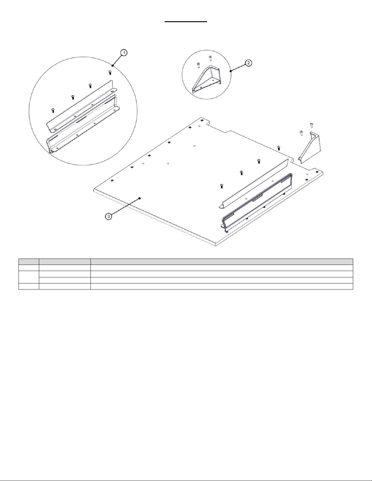
1-70-008 – H User Manual
- Spirit Plus 5600
CHG
Hospital
Beds
Page 94
of
103
HEAD DECK
ITEM
KIT #
KIT DESCRIPTION
1 S0419
Service Kit, Mattress Keeper & Stiffener
S0050
-A
Service Kit,
Corner Mattress Keeper A (PL Head/PR Foot)
S0050
-B
Service Kit
, Corner Mattress Keeper B (PR Head/PL Foot)
3 S0089
Service Kit,
Head Deck Assembly Complete
2
Page 95
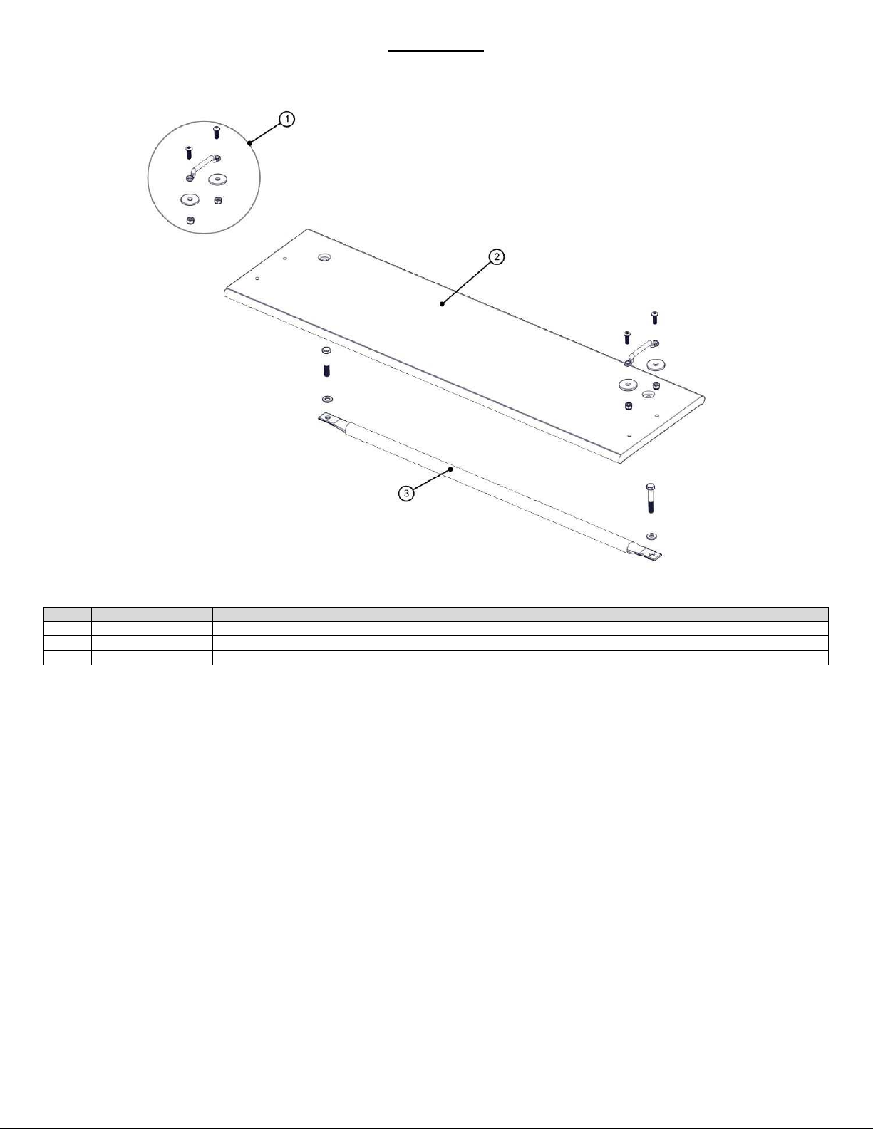
1-70-008 – H User Manual
- Spirit Plus 5600
CHG
Hospital
Beds
Page 95
of
103
SEAT DECK
ITEM
KIT #
KIT DESCRIPTION
1 S0072
Service Kit, Restraint Loop
2 S0144
Service Kit,
Seat Deck Assembly Complete
3 S0264
Service Kit
, Seat D
eck Support Tube
Page 96
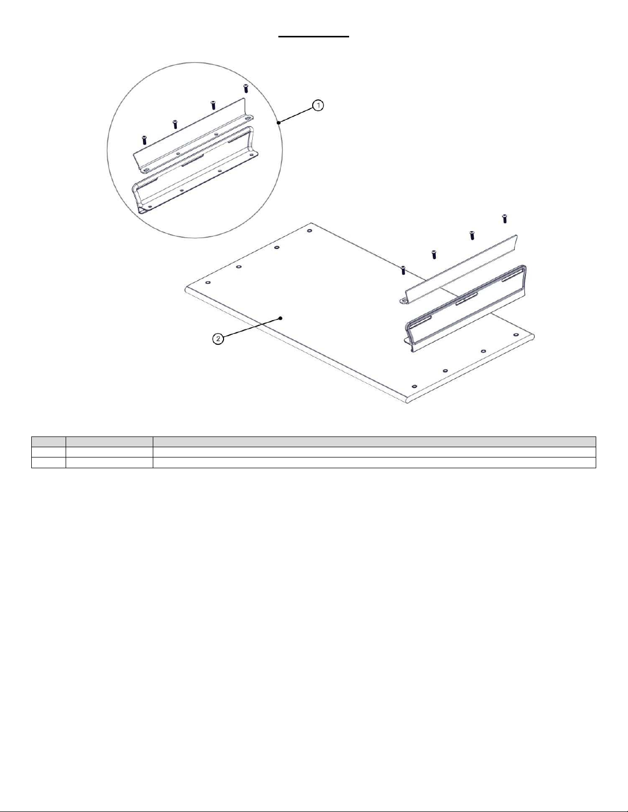
1-70-008 – H User Manual
- Spirit Plus 5600
CHG
Hospital
Beds
Page 96
of
103
KNEE DECK
ITEM
KIT #
KIT DESCRIPTION
1 S0419
Service Kit, Mattress Keeper & Stiffener
2 S0090
Service Kit,
Knee Deck Assembly Complete
Page 97
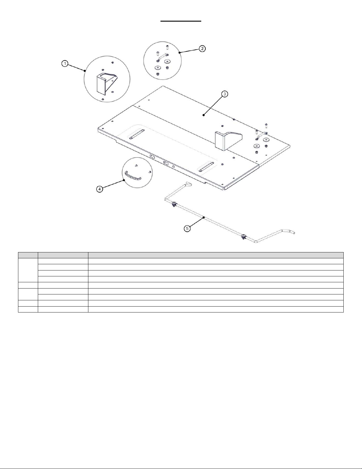
1-70-008 – H User Manual
- Spirit Plus 5600
CHG
Hospital
Beds
Page 97
of
103
FOOT DECK
ITEM
KIT #
KIT DESCRIPTION
S0279
Service Kit, Foot Deck Extension Corne
r Mattress Keeper A (PR Foot)
S0280
Service Kit, Foot Deck Extension Corner Mattress Keeper B (PL Foot)
S0050
-A
Service Kit,
Corner Mattress Keeper A (PL Head/PR Foot)
S0050
-B
Service Kit, Corner Mattress Keeper B (PR Head/PL Foot)
2 S0072
Service K
it, Restraint Loop
SK0086 Service Kit, Foot Deck Assembly Complete + Extension
S0010
Service Kit, Foot Deck Assembly Complete
4 S0174
Service Kit, Extension Handle
5 SK0119 Service Kit, Foot Bail
1
3
Page 98
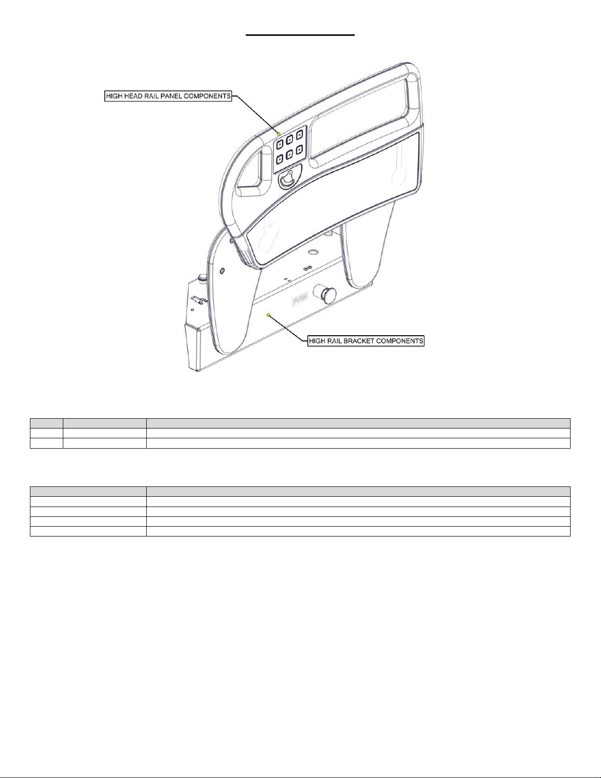
1-70-008 – H User Manual
- Spirit Plus 5600
CHG
Hospital
Beds
Page 98
of
103
HIGH HEAD RAILS
ITEM
KIT #
KIT DESCRIPTION
1
SEE HIGH HEAD RAIL PANEL COMPONENTS
2
SEE HIGH HEAD RAIL BRACKET COMPONENTS
KIT #
KIT DESCRIPTION
S0095
Service Kit, High Head Rail & Bracket Assembly, PR
S0096
Service Kit, High Head Rail & Bracket Assembly, PL
S0249
Service Kit, High Head Rail & Bracket Assembly, PR FILLED
S0250
Service Kit, High Head Rail & Bracket Assembly, PL FILLED
COMPLETE RAIL ASSEMBLIES
Page 99
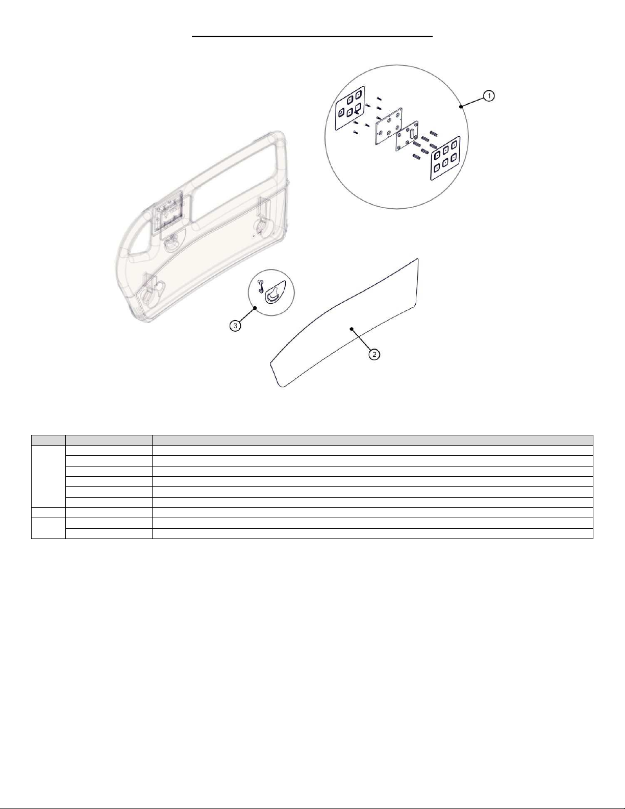
1-70-008 – H User Manual
- Spirit Plus 5600
CHG
Hospital
Beds
Page 99
of
103
HIGH HEAD RAIL PANEL COMPONENTS
ITEM
KIT #
KIT DESCRIPTION
S0070
Service Kit, Head Siderail PCB Replacement Kit (PL)
S0071
Service Kit, Head Siderail PCB Replacement Kit (PR)
S0109
Service Kit, Side Rail Control Overlay A (PL Outside)
S0110
Service Kit, Side Rail Co
ntrol Overlay B (PL Inside)
S0111
Service Kit, Side Rail Control Overlay C (PR Inside)
S0112
Service Kit, Side Rail Control Overlay D (PR Outside)
2 S0087
-XX
Service Kit, High Head Rail Inlays, Pair (where XX signifies Colour Option)
S0420
Service
Kit, Head Angle Overlay Pendulum (PL)
S0421
Service Kit, Head Angle Overlay Pendulum (PR)
1
3
Page 100
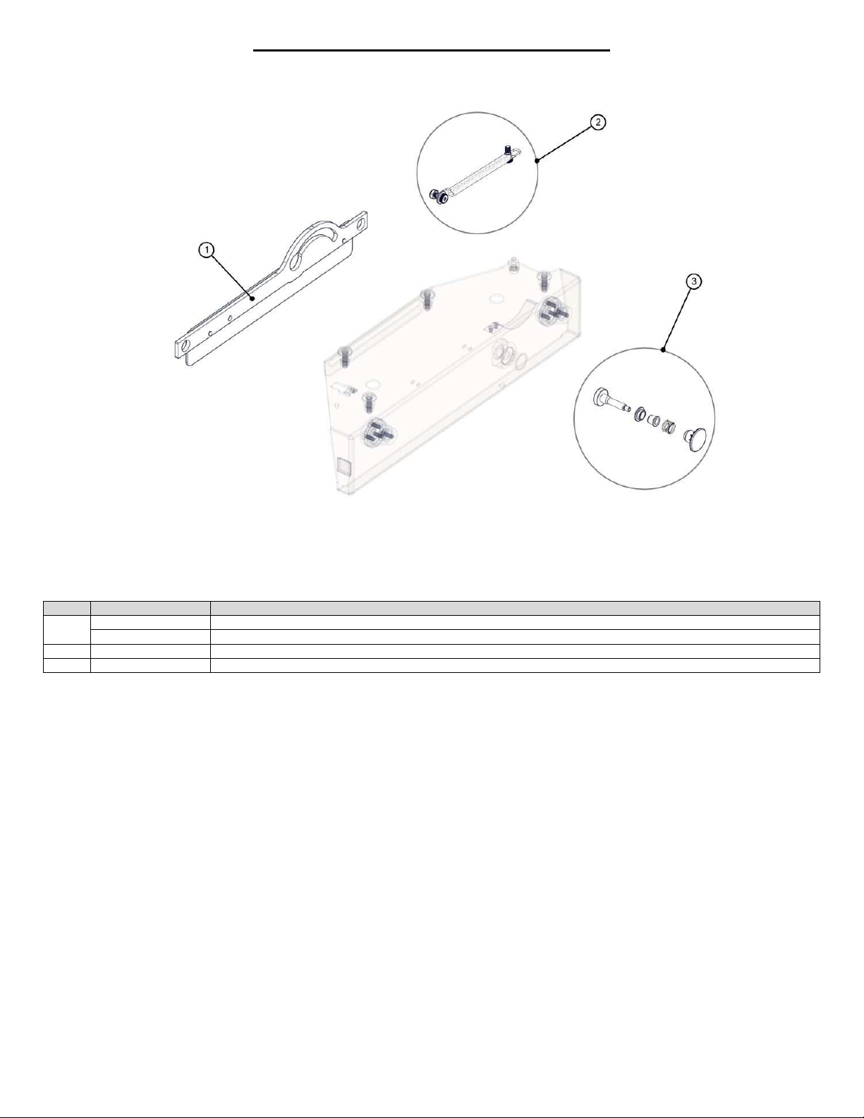
1-70-008 – H User Manual
- Spirit Plus 5600
CHG
Hospital
Beds
Page
100 of
103
HIGH HEAD RAIL BRACKET COMPONENTS
ITEM
KIT #
KIT DESCRIPTION
S0434
Service Kit, High Rail Linkage, Head PR Dampened
S0435
Service Kit, High Rail Linka
ge, Head PL Dampened
2 S0424
Service Kit, High Rail Dampening Spring
3 S0368
Service Kit, High Side Rail Knob & Latch Pin Assembly
1
 Loading...