

Page 1
5050 & 5051 Stretcher Chair
OPERATIONS MANUAL
For Parts or Technical Assistance:
1-800-327-0770
Page 2

Table of Contents
Introduction
Specifications 2. . . . . . . . . . . . . . . . . . . . . . . . . . . . . . . . . . . . . . . . . . . . . . . . . . . . . . . . . . . . . . . . . . . . . . . . . . . .
Warning / Caution / Note Definition 2. . . . . . . . . . . . . . . . . . . . . . . . . . . . . . . . . . . . . . . . . . . . . . . . . . . . . . . . .
Operation Guide
Base Pedal Operation 4. . . . . . . . . . . . . . . . . . . . . . . . . . . . . . . . . . . . . . . . . . . . . . . . . . . . . . . . . . . . . . . . . . . .
Raising And Lowering Litter Height 5. . . . . . . . . . . . . . . . . . . . . . . . . . . . . . . . . . . . . . . . . . . . . . . . . . . . . . . . .
Applying the Brake System 5. . . . . . . . . . . . . . . . . . . . . . . . . . . . . . . . . . . . . . . . . . . . . . . . . . . . . . . . . . . . . . . .
Operating the Steer Caster 5. . . . . . . . . . . . . . . . . . . . . . . . . . . . . . . . . . . . . . . . . . . . . . . . . . . . . . . . . . . . . . . .
Trendelenburg/Reverse Trendelenburg Positioning 6. . . . . . . . . . . . . . . . . . . . . . . . . . . . . . . . . . . . . . . . . . . .
Using the Siderails 6. . . . . . . . . . . . . . . . . . . . . . . . . . . . . . . . . . . . . . . . . . . . . . . . . . . . . . . . . . . . . . . . . . . . . . .
Using the Patient Transfer System 7. . . . . . . . . . . . . . . . . . . . . . . . . . . . . . . . . . . . . . . . . . . . . . . . . . . . . . . . . .
Operating the Fowler 8, 9. . . . . . . . . . . . . . . . . . . . . . . . . . . . . . . . . . . . . . . . . . . . . . . . . . . . . . . . . . . . . . . . . . .
Operating the Adjustable Foot Rest 10. . . . . . . . . . . . . . . . . . . . . . . . . . . . . . . . . . . . . . . . . . . . . . . . . . . . . . . .
Operating the Optional Independent Foot Section
Dependent (Chair Mode) Operation 11. . . . . . . . . . . . . . . . . . . . . . . . . . . . . . . . . . . . . . . . . . . . . . . . . . . . . .
Independent Operation 11. . . . . . . . . . . . . . . . . . . . . . . . . . . . . . . . . . . . . . . . . . . . . . . . . . . . . . . . . . . . . . . .
Resetting the Foot Section (Returning To Chair Mode) 11. . . . . . . . . . . . . . . . . . . . . . . . . . . . . . . . . . . . .
Positioning the Push Bar 12. . . . . . . . . . . . . . . . . . . . . . . . . . . . . . . . . . . . . . . . . . . . . . . . . . . . . . . . . . . . . . . . .
Removing And Reinstalling the Mattress 12. . . . . . . . . . . . . . . . . . . . . . . . . . . . . . . . . . . . . . . . . . . . . . . . . . . .
Operating the Enhanced Clearance Head Piece 13. . . . . . . . . . . . . . . . . . . . . . . . . . . . . . . . . . . . . . . . . . . . .
Using the Optional Inflatable Head Support Cushion 13. . . . . . . . . . . . . . . . . . . . . . . . . . . . . . . . . . . . . . . . .
Using the Optional Wrist Rests 14. . . . . . . . . . . . . . . . . . . . . . . . . . . . . . . . . . . . . . . . . . . . . . . . . . . . . . . . . . . .
Using the Optional Tethered I.V. Pole 14. . . . . . . . . . . . . . . . . . . . . . . . . . . . . . . . . . . . . . . . . . . . . . . . . . . . . .
Preventative Maintenance
Cleaning 15. . . . . . . . . . . . . . . . . . . . . . . . . . . . . . . . . . . . . . . . . . . . . . . . . . . . . . . . . . . . . . . . . . . . . . . . . . . . . . .
Checklist 16. . . . . . . . . . . . . . . . . . . . . . . . . . . . . . . . . . . . . . . . . . . . . . . . . . . . . . . . . . . . . . . . . . . . . . . . . . . . . . .
Limited Warranty
Obtaining Parts and Service 17. . . . . . . . . . . . . . . . . . . . . . . . . . . . . . . . . . . . . . . . . . . . . . . . . . . . . . . . . . . . .
Supplemental Warranty Coverage 17. . . . . . . . . . . . . . . . . . . . . . . . . . . . . . . . . . . . . . . . . . . . . . . . . . . . . . . .
Return Authorization 18. . . . . . . . . . . . . . . . . . . . . . . . . . . . . . . . . . . . . . . . . . . . . . . . . . . . . . . . . . . . . . . . . . . .
Freight Damage Claims 18. . . . . . . . . . . . . . . . . . . . . . . . . . . . . . . . . . . . . . . . . . . . . . . . . . . . . . . . . . . . . . . . .
Page 3

Introduction
INTRODUCTION
This manual is designed to assist you with the operation of the 5050 & 5051 Stretcher Chair. Read it thoroughly before using the equipment.
SPECIFICATIONS
Maximum Weight Capacity 400 pounds
Overall Stretcher Length/Width 76”/30”
Patient Surface Length/Width (Mattress) 74”/24”
Minimum/Maximum Stretcher Height (Floor to Litter Surface) 22”/33.5”
Foot Section Articulation 0_ to 80_
Fowler Articulation 0_ to 90_
Trendelenberg/Reverse Trendelenberg Articulation +18_/-18 _
Stryker reserves the right to change specifications without notice.
WARNING / CAUTION / NOTE DEFINITION
The words WARNING, CAUTION and NOTE carry special meanings and should be carefully reviewed.
WARNING
The personal safety of the patient or user may be involved. Disregarding this information could result in injury
to the patient or user.
CAUTION
These instructions point out special procedures or precautions that must be followed to avoid damaging the
equipment.
NOTE
This provides special information to make maintenance easier or important instructions clearer.
2
Page 4

Introduction
Before operating this stretcher, it is important to read and understand all information in this manual.
Carefully read and strictly follow the warnings listed on this page.
WARNING
Patient entry, egress and transfer from the Model 5050 & 5051 Stretcher Chair must always be done at the
center side locations with the siderail lowered. At no time should patients be allowed to enter or exit from
the ends of the Stretcher Chair, unless it is in the full chair position (back section up/foot section down). Improper entry, egress or transfer may cause the Stretcher Chair to tip or become unstable which may result
in patient injury.
To avoid risk of tipping resulting in patient injury, never leave the Stretcher Chair unattended in the horizontal
position. Always return the unit to the chair position when not in use. Warning labels are located at the head
and foot end of the Stretcher Chair frame stating: “DO NOT SIT ON END. TIPPING MAY OCCUR. KEEP
IN THE CHAIR POSITION WHEN NOT IN USE.”
Always apply the caster brakes when a patient is getting on or off the stretcher. Push on the stretcher to ensure the brakes are securely locked. Always engage the brakes unless the stretcher is being moved. Injury
could result if the stretcher moves while a patient is getting on or off the stretcher . I f brakes do not hold properly, refer to your stretcher maintenance manual for a brake adjustment procedure.
Be sure to remove any equipment that may be in the way before lowering the Stretcher Chair or damage could
occur to the equipment or the Stretcher Chair.
Be sure the siderail latching mechanism is working properly and the siderail is latching securely at all times
or patient injury could result. If the siderails are not latching properly, refer to your stretcher maintenance
manual for adjustment details.
To avoid having the siderail swing down freely when the latch is released, securely hold the siderail either
underneath or from the end when raising or lowering it. Failure to do so could cause damage to the Stretcher
Chair or injury to the user.
To avoid possible injury, patients should be appropriately restrained at all times.
When using the patient transfer system, always lock the brakes on all stretchers or beds being used and
always be sure the transfer surface is securely on the surface of the mating stretcher or bed. The Stretcher
Chair patient surface and the surface of the mating stretcher or bed must be at the same height before the
patient is transferred. Failure to follow these guidelines may result in an unstable surface and patient injury .
Be sure the brakes on both the Stretcher Chair and the mating bed or stretcher have been applied before
proceeding with the patient transfer.
Keep fingers/hands clear of the area between the frame and the Fowler when lowering the Fowler or injury
could result.
Hold the foot rest firmly while repositioning it to prevent it from falling to the lowest position and causing injury
or equipment damage.
Do not stand on the foot rest. Tipping may occur which could result in patient or user injury.
The foot section will release during the return to dependent operation (Chair Mode). Hold the end securely
and support it when repositioning.
The weight of the patient’s head is resting on the head piece and must be supported by the operator when
the latches are released and the head piece is being positioned. Failure to adequately support the head piece
while positioning the head could result in patient injury.
CAUTION
The dual articulating headpiece is designed to provide precision surgical positioning. Be sure to treat it with
care. The unit should be routinely checked to ensure optimal performance. In the event of any impact or
overload of the headpiece, be sure the unit is working properly and supports the intended load. Verify the
adjustment gears lock and release properly and, if necessary, refer to the adjustment procedure in the maintenance manual.
3
Page 5
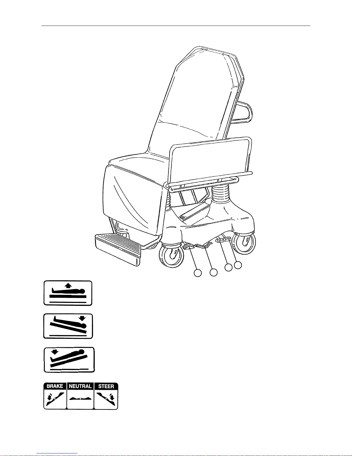
BASE PEDAL OPERATION
Operation Guide
B
C
D
A
(A)
Pump to raise litter.
(B) Depress to lower head end (Trendelenburg).
(C) Depress to lower foot end (Reverse Trendelenburg).
To lower both ends of the stretcher, depress
both Trendelenburg pedals at the same time.
(D) Brake and Steer functions
4
Page 6

Operation Guide
WARNING
Patient entry, egress and transfer from the Model 5050 Stretcher Chair must always be done at the center
side locations with the siderail lowered. At no time should patients be allowed to enter or exit from the ends
of the Stretcher Chair, unless it is in the full chair position (back section up/foot section down). Improper entry ,
egress or transfer may cause the Stretcher Chair to tip or become unstable which may result in patient injury .
RAISING AND LOWERING LITTER HEIGHT
NOTE
For user convenience, pump pedals and control pedals are located on both sides of the Stretcher Chair.
CAUTION
Be sure to move any equipment that may be in the way before raising or lowering the Stretcher Chair height
or damage could occur to the equipment or the Stretcher Chair.
To raise the litter height, pump foot pedal (A) repeatedly until desired height is achieved. (See illustration,
page 4).
To lower the litter height, activate both pedals (B) and (C) using the same foot. Depress pedal (B) to lower
the head end only and depress pedal (C) to lower the foot end only of the Stretcher Chair. (See illustration,
page 4).
WARNING
To avoid risk of tipping resulting in patient injury, never leave the Stretcher Chair unattended in the horizontal
position. Always return the unit to the chair position when not in use. Warning labels are located at the head
and foot end of the Stretcher Chair frame stating: “DO NOT SIT ON END. TIPPING MAY OCCUR. KEEP
IN THE CHAIR POSITION WHEN NOT IN USE.”
APPLYING THE BRAKE SYSTEM
To engage the brakes on the Stretcher Chair, push fully down on the side of pedal (D) closest to the head
end of the stretcher. (See illustration page 4).
WARNING
Always apply the caster brakes when a patient is getting on or off the stretcher. Push on the stretcher to ensure the brakes are securely locked. Always engage the brakes unless the stretcher is being moved. Injury
could result if the stretcher moves while a patient is getting on or off the stretcher . I f brakes do not hold properly, refer to your stretcher maintenance manual for a brake adjustment procedure.
NOTE
For user convenience, the Brake/Steer pedal is located on both sides of the Stretcher Chair.
OPERATING THE STEER CASTER
To engage the steer caster, push fully down on the side of pedal (D) closest to the foot end of the stretcher
(See illustration page 4). This will lock the steering caster (foot end, right). The Stretcher Chair will pivot
around it when cornering.
5
Page 7

Operation Guide
TRENDELENBURG/REVERSE TRENDELENBURG POSITIONING
NOTE
Litter height must be raised first in order to achieve a trend. or reverse trend. position.
CAUTION
Be sure to remove any equipment that may be in the way before lowering the Stretcher Chair or damage could
occur to the equipment or the Stretcher Chair.
For Trendelenburg positioning (head down), depress pedal (B). (See illustration, page 4).
For Reverse Trendelenburg positioning (foot down), depress pedal (C). (See illustration, page 4).
NOTE
The higher the litter is before pedals (B) or (C) are activated, the greater the trend. or reverse trend. angle
will be. (Maximum trend. angle is +18_. Maximum reverse trend. angle is -18_).
USING THE SIDERAILS
A
WARNING
Be sure the siderail latching mechanism is working properly and the siderail is latching securely at all times
or patient injury could result. If the siderails are not latching properly, refer to your stretcher maintenance
manual for adjustment details.
To avoid having the siderail swing down freely when the latch is released, securely hold the siderail either
underneath or from the end when raising or lowering it. Failure to do so could cause damage to the Stretcher
Chair or injury to the user.
To avoid possible injury, patients should be appropriately restrained at all times.
To raise the siderails, pull out the locking latch (A) while securely holding the siderail and raise the siderail
to the full up position until the latch engages.
To lower the siderails, pull out the locking latch (A) while securely holding the siderail and lower the siderail
to the full down position until the latch engages. The siderail will be partially tucked away under the litter.
6
Page 8

Operation Guide
USING THE PATIENT TRANSFER SYSTEM
C
B
A
WARNING
When using the patient transfer system, always lock the brakes on all stretchers or beds being used and
always be sure the transfer surface is securely on the surface of the mating stretcher or bed. The Stretcher
Chair patient surface and the surface of the mating stretcher or bed must be at the same height before the
patient is transferred. Failure to follow these guidelines may result in an unstable surface and patient injury .
Be sure the Stretcher Chair is as close to the mating surface as possible and at the same height or slightly
higher (not to exceed 1”).
Pull the release knob (A) and lower the siderail down onto the mating stretcher or bed. The siderail arm rest
(B) should be flat to serve as a lead to the transfer surface. If it is not, push the arm rest toward the foot end
of the stretcher to release the arm rest latch (C), then rotate the arm rest up so it is parallel with the siderail.
CAUTION
Be sure the brakes on both the Stretcher Chair and the mating bed or stretcher have been applied before
proceeding with the patient transfer.
Using a sheet, draw the patient onto the mating bed or stretcher.
7
Page 9

Operation Guide
OPERATING THE FOWLER (5050)
A
B
WARNING
Keep fingers/hands clear of the area between the frame and the Fowler when lowering the Fowler or injury
could result.
Squeeze red handle (A) toward the Fowler frame (not toward item (B) push bar) for pneumatic assist in raising
the Fowler. Remove hands from handle when desired height is achieved.
To lower the Fowler, squeeze red handle (A) toward the Fowler frame (not toward item (B) push bar) and push
down until the Fowler has reached the desired height. Remove hands from handle when desired height is
achieved.
8
Page 10

Operation Guide
OPERATING THE FOWLER (5051)
A
Squeeze red handle (A) toward the Fowler frame for pneumatic assist in raising the Fowler. Remove hands
from handle when desired height is achieved.
A
WARNING
Operation of the pneumatic Fowler is a manual procedure. Use caution when raising the Fowler while a patient is on the stretcher. Use proper lifting techniques and get additional assistance, if necessary. Failure
to use proper lifting techniques could cause injury to the operator.
To lower the Fowler, squeeze red handle (A) toward the Fowler frame and push down until the Fowler has
reached the desired height. Remove hands from handle when desired height is achieved.
WARNING
Keep fingers/hands clear of the area between the frame and the Fowler when lowering the Fowler or injury
could result.
9
Page 11

Operation Guide
OPERATING THE ADJUSTABLE FOOT REST
WARNING
Hold the foot rest firmly while repositioning it to prevent it from falling to the lowest position and causing injury
or equipment damage.
Do not stand on the foot rest. Tipping may occur which could result in patient or user injury.
NOTE
The leg section must be down in order to adjust the foot rest. The foot rest must be rotated halfway up to
the leg section in order to adjust the height.
To raise the foot rest:
Rotate the foot rest halfway up, then slide it toward the butt section until you reach the desired height. While
pulling the foot rest out toward you, rotate it down to a horizontal position. The foot rest will drop into the next
lower position.
To lower the foot rest:
While grasping the foot rest firmly , rotate it up and push back on it. When it clears its latch, it will drop down.
Rotate the foot rest down to a horizontal position.
10
Page 12

Operation Guide
OPERATING THE OPTIONAL INDEPENDENT FOOT SECTION
A
Dependent (Chair Mode) Operation
During dependent (Chair Mode) operation, the foot section will articulate with the Fowler when going from
the sitting to the supine position. In order for the foot section to be in Chair Mode, the red handle (A), located
on both sides of the foot section, must be pointing toward the head end of the Stretcher Chair.
Independent Operation
When the foot section is in the Independent Mode, it can articulate to any position independent of the Fowler.
To operate the foot section in the Independent Mode, rotate the red handle (A) so it is pointing toward the foot
end of the Stretcher Chair, as shown in the illustration above. The foot section is now locked into position,
independent of the Fowler. To reposition the foot section, hold the foot end securely , pull the red handle (A)
toward you and hold it in that position. Lift or lower the foot section to the desired position and release the
red handle to lock it in place.
Resetting the Foot Section (Returning to Chair Mode)
CAUTION
The foot section will release during the return to dependent operation (Chair Mode). Hold the end securely
and support it when repositioning.
While supporting the foot section, rotate the red handle (A) on the foot section so it is pointing toward the head
end of the Stretcher Chair. Lift or lower the foot section until it locks in place. Raise or lower the Fowler and
assure the foot section moves with it.
11
Page 13

POSITIONING THE PUSH BAR
Operation Guide
A
To lower the push bar, pull back the red release knob (A) while holding onto the push bar. Swing the push
bar into the full down position until the latch engages.
To raise the push bar, pull back the red release knob (A) while holding onto the push bar. Swing the push
bar into the full up position until the latch engages.
REMOVING AND REINSTALLING THE MATTRESS
When removing the mattress, it is important to start at the head end of the Stretcher Chair. Pull on the head
end of the mattress to release it from the Velcro on the Fowler and midsection. Once it is free of the Velcro,
pull the mattress toward the head end of the Stretcher Chair to disengage the mattress from the foot section
sliding tabs. (The tabs keep the foot section of the mattress close to the litter surface during articulation.)
To reinstall the mattress, slide the pockets on the foot end back over the sliding tabs. Place the mattress down
the length of the litter surface and press firmly on the Fowler and midsection to secure the Velcro strips.
12
Page 14

Operation Guide
OPERATING THE ENHANCED CLEARANCE HEAD PIECE
To operate the enhanced clearance head piece, grasp either handle under the
head section and squeeze. Handle (A) releases the latch and rotates the
head piece on axis ”A”. Handle (B) releases the other latch and rotates
(Cut-Away View)
the head section on axis ”B”. For ease of operation, it is recom-
mended that only one latch be released at a time.
AXIS
AXIS
WARNING
The weight of the patient’s head is resting on the head piece and must be supported by the operator when
the latches are released and the head piece is being positioned. Failure to adequately support the head piece
while positioning the head could result in patient injury.
CAUTION
The dual articulating headpiece is designed to provide precision surgical positioning. Be sure to treat it with
care. The unit should be routinely checked to ensure optimal performance. In the event of any impact or
overload of the headpiece, be sure the unit is working properly and supports the intended load. Verify the
adjustment gears lock and release properly and, if necessary, refer to the adjustment procedure in the maintenance manual.
USING THE OPTIONAL INFLATABLE HEAD SUPPORT CUSHION
The optional inflatable head support cushion has two internal air bladders. Squeeze the bulb (A) to inflate the bladders and provide more stability for the patient’s head. Press the release valve (B) to deflate the
bladders.
B
A
13
Page 15

Operation Guide
USING THE OPTIONAL WRIST RESTS
There are two optional wrist rests available; standard and temporal .
To use the wrist rest, insert the support
tube (A) into the socket in the Fowler head
piece assembly. Turn knob (B) clockwise
to secure the wrist rest assembly.
To adjust the height of the wrist rest, turn
knob (C) counterclockwise to loosen it.
Raise or lower the wrist rest to the desired
height, and turn the knob clockwise to
tighten it and hold the wrist rest in place.
The ”U” shaped rest (D) can be pivoted up
and away from the patient when the wrist
rest is not in use.
USING THE OPTIONAL TETHERED I.V. POLE
To use the tethered I.V. pole:
D
D
C
A
C
1
B
B
A
2
1. Remove the I.V. pole from the storage trough under the
litter and insert into the receptacle on the corner of the
litter frame.
2. To raise the height of the pole, turn knob (A) counterclockwise and pull up on the telescoping portion (B)
of the pole to raise it to the desired height.
3. Turn knob (A) clockwise to lock the telescoping portion
in place.
B
A
14
Page 16

Cleaning
Hand wash all surfaces of the stretcher with warm water and mild detergent. Dry thoroughly. DO NOT
STEAM CLEAN, PRESSURE WASH, HOSE OFF OR ULTRASONICALLY CLEAN. Using these methods
of cleaning is not recommended and may void this product’s warranty.
Clean Velcro AFTER EACH USE. Saturate Velcro with disinfectant and allow disinfectant to evaporate. (Appropriate disinfectant for nylon Velcro should be determined by the hospital.)
In general, when used in those concentrations recommended by the manufacturer, either phenolic type or
quaternary type disinfectants can be used. Iodophor type disinfectants are not recommended for use because staining may result. The following products have been tested and have been found not to have a harmful effect WHEN USED IN ACCORDANCE WITH MANUFACTURERS RECOMMENDED DILUTION.*
*MANUFACTURER’S
TRADE NAME DISINFECTANT
TYPE
A33 Quaternary Airwick (Professional Products Division) 2 ounces/gallon
A33 (dry) Quaternary Airwick (Professional Products Division) 1/2 ounce/gallon
Beaucoup Phenolic Huntington Laboratories 1 ounce/gallon
Blue Chip Quaternary S.C. Johnson 2 ounces/gallon
Elimstaph Quaternary Walter G. Legge 1 ounce/gallon
Franklin Pheno-
mysan F2500
Franklin Sentinel Quaternary Purex Corporation 2 ounces/gallon
Galahad Phenolic Puritan Churchill Chemical Company 1 ounce/gallon
Hi-Tor Quaternary Huntington Laboratories 1/2 ounce/gallon
LPH Phenolic Vestal Laboratories 1/2 ounce/gallon
Matar Phenolic Huntington Laboratories 1/2 ounce/gallon
Omega Quaternary Airwick (Professional Products Division) 1/2 ounce/gallon
Quanto Quaternary Huntington Laboratories 1 ounce/gallon
Sanikleen Quaternary West Chemical Products 2 ounces/ gallon
Sanimaster II Quaternary Service Master 1 ounce/gallon
Vesphene Phenolic Vestal Laboratories 1 1/4 ounce/ gallon
Phenolic Purex Corporation 1 1/4 ounce/gallon
MANUFACTURER
RECOMMENDED
DILUTION
Quaternary Germicidal Disinfectants, used as directed, and/or Chlorine Bleach products, typically 5.25% So dium Hypochlorite in dilutions ranging between 1 part bleach to 100 parts water, and 2 parts bleach
to 100 parts water are not considered mild detergents. These products are corrosive in nature and
may cause damage to your stretcher if used improperly. If these types of products are used to clean
Stryker patient handling equipment, measures must be taken to insure the stretchers are rinsed with clean
water and thoroughly dried following cleaning. Failure to properly rinse and dry the stretchers will leave a corrosive residue on the surface of the stretcher, possibly causing premature corrosion of critical components.
NOTE
Failure to follow the above directions when using these types of cleaners may void this product’s warranty.
REMOVAL OF IODINE COMPOUNDS
This solution may be used to remove iodine stains from mattress cover and foam footrest pad surfaces.
1. Use a solution of 1-2 tablespoons Sodium Thiosulfate in a pint of warm water to clean the stained area.
Clean as soon as possible after staining occurs. If stains are not immediately removed, allow solution to
soak or stand on the surface.
2. Rinse surfaces which have been exposed to the solution in clear water before returning bed to service.
15
Page 17

Preventative Maintenance
CHECKLIST
All fasteners secure (reference all assembly prints)
Siderails move and latch properly
All casters lock with brake pedal engaged
Steer function working properly
All casters secure and swivel properly
Body restraints intact and working properly
Oxygen bottle holder intact and operating properly
Fowler/leg articulation operating properly
Trendelenburg/Reverse Trendelenburg operating properly
Optional articulating head piece locking and releasing properly - check immediately if the head piece
is bumped on a door, wall or other obstacle while the stretcher is being moved
Transfer surface intact and working properly
No rips or cracks in mattress cover
No leaks at hydraulic connections
Hydraulic jacks holding properly
Hydraulic drop rate set properly
Hydraulic oil level sufficient
Lubricate where required, including the brake adjuster assembly and brake cam and the independent
foot section mechanisms
Serial No.______________
______________
______________
______________
______________
Completed By:_________________________________ Date:_____________
NOTE
Preventative maintenance should be performed at a minimum of annually. A preventative maintenance program should be established for all Stryker Medical equipment. Preventative maintenance may need to be
performed more frequently based on the usage level of the product.
16
Page 18

Warranty
Limited Warranty:
Stryker Medical Division, a division of Stryker Corporation, warrants to the original purchaser that its products
should be free from defects in material and workmanship for a period of one (1) year after date of delivery.
Stryker’s obligation under this warranty is expressly limited to supplying replacement parts and labor for, or
replacing, at its option, any product which is, in the sole discretion of Stryker, found to be defective. Stryker
warrants to the original purchaser that the frame and welds on its beds will be free from structural defects
for as long as the original purchaser owns the bed. If requested by Stryker, products or parts for which a
warranty claim is made shall be returned prepaid to Stryker’s factory. Any improper use or any alteration or
repair by others in such manner as in Stryker’s judgement affects the product materially and adversely shall
void this warranty. Any repair of Stryker products using parts not provided or authorized by Stryker shall void
this warranty. No employee or representative of Stryker is authorized to change this warranty in any way.
Stryker Medical stretchers are designed for a 10 year expected life under normal use conditions and appropriate periodic maintenance as described in the maintenance manual for each device.
This statement constitutes Stryker’s entire warranty with respect to the aforesaid equipment. STRYKER
MAKES NO OTHER WARRANTY OR REPRESENTATION, EITHER EXPRESSED OR IMPLIED, EXCEPT
AS SET FORTH HEREIN. THERE IS NO WARRANTY OF MERCHANTABILITY AND THERE ARE NO
WARRANTIES OF FITNESS FOR ANY PARTICULAR PURPOSE. IN NO EVENT SHALL STRYKER BE
LIABLE HEREUNDER FOR INCIDENTAL OR CONSEQUENTIAL DAMAGES ARISING FROM OR IN ANY
MANNER RELATED TO SALES OR USE OF ANY SUCH EQUIPMENT.
To Obtain Parts and Service:
Stryker products are supported by a nationwide network of dedicated Stryker Field Service Representatives.
These representatives are factory trained, available locally, and carry a substantial spare parts inventory to
minimize repair time. Simply call your local representative, or call Stryker Customer Service at (800)
327-0770.
Service Contract Coverage:
Stryker has developed a comprehensive program of service contract options designed to keep your equipment operating at peak performance at the same time it eliminates unexpected costs. We recommend that
these programs be activated before the expiration of the new product warranty to eliminate the potential of
additional equipment upgrade charges.
A SERVICE CONTRACT HELPS TO:
S Ensure equipment reliability
S Stabilize maintenance budgets
S Diminish downtime
S Establish documentation for JCAHO
S Increase product life
S Enhance trade-in value
S Address risk management and safety
17
Page 19

Warranty
Stryker offers the following service contract programs:
SPECIFICATIONS GOLD SILVER PM* ONLY
Annually scheduled preventative maintenance X X
All parts,** labor, and travel X X
Unlimited emergency service calls X X
Priority one contact; two hour phone response X X X
Most repairs will be completed within 3 business days X X
JCAHO documentation X X X
On-site log book w/ preventative maintenance & emergency service records X
Factory-trained Stryker Service Technicians X X X
Stryker authorized parts X X X
End of year summary X
Stryker will perform all service during regular business hours (9-5) X X X
* Replacement parts and labor for products under PM contract will be discounted.
** Does not include any disposable items, I.V. poles (except for Stryker HD permanent poles), mattresses, or damage re-
sulting from abuse.
Stryker Medical also offers personalized service contracts.
Pricing is determined by age, location, model and condition of product.
For more information on our service contracts,
please call your local representative or call (800) 327-0770 (option #2).
Return Authorization:
Merchandise cannot be returned without approval from the Stryker Customer Service Department. An authorization number will be provided which must be printed on the returned merchandise. Stryker reserves the
right to charge shipping and restocking fees on returned items.
SPECIAL, MODIFIED, OR DISCONTINUED ITEMS NOT SUBJECT TO RETURN.
Damaged Merchandise:
ICC Regulations require that claims for damaged merchandise must be made with the carrier within fifteen
(15) days of receipt of merchandise. DO NOT ACCEPT DAMAGED SHIPMENTS UNLESS SUCH DAMAGE
IS NOTED ON THE DELIVERY RECEIPT AT THE TIME OF RECEIPT. Upon prompt notification, Stryker
will file a freight claim with the appropriate carrier for damages incurred. Claim will be limited in amount to
the actual replacement cost. In the event that this information is not received by Stryker within the fifteen
(15) day period following the delivery of the merchandise, or the damage was not noted on the delivery receipt
at the time of receipt, the customer will be responsible for payment of the original invoice in full.
Claims for any short shipment must be made within thirty (30) days of invoice.
International Warranty Clause:
This warranty reflects U.S. domestic policy. W arranty outside the U.S. may vary by country. Please contact
your local Stryker Medical representative for additional information.
18
Page 20

European Representative
Stryker France Phone: 33148632290
BP 50040-95946 Roissy Ch. de Gaulle Fax: 33148632175
Cedex-France
6300 Sprinkle Road, Kalamazoo, MI 49001-9799 (800) 327-0770
www.strykermedical.com
DH 8/02 5051-90-2 REV F
 Loading...