

Page 1
IMPORTANT
File in your
maintenance
records
Modular Patient System (MPS) 3000 Bed
MAINTENANCE MANUAL
For Parts or Technical Assistance
1–800–327–0770
Page 2

Table of Contents
CHAPTER ONE – INTRODUCTION
S 1.1 Bed Specifications 9. . . . . . . . . . . . . . . . . . . . . . . . . . . . . . . . . . . . . . . . . . . . . . . . . . . . . . . . . . . .
S 1.2 Safety 9, 10. . . . . . . . . . . . . . . . . . . . . . . . . . . . . . . . . . . . . . . . . . . . . . . . . . . . . . . . . . . . . . . . . . . . . . .
S 1.3 Warranty 11, 12. . . . . . . . . . . . . . . . . . . . . . . . . . . . . . . . . . . . . . . . . . . . . . . . . . . . . . . . . . . . . . . . . . .
S 1.4 Recommended Parts Kits 13. . . . . . . . . . . . . . . . . . . . . . . . . . . . . . . . . . . . . . . . . . . . . . . . . . .
S 1.5 Replacement Parts Kits 14, 15. . . . . . . . . . . . . . . . . . . . . . . . . . . . . . . . . . . . . . . . . . . . . . . . . .
S 1.6 Cleaning 16. . . . . . . . . . . . . . . . . . . . . . . . . . . . . . . . . . . . . . . . . . . . . . . . . . . . . . . . . . . . . . . . . . . . . .
S 1.7 Preventative Maintenance 17. . . . . . . . . . . . . . . . . . . . . . . . . . . . . . . . . . . . . . . . . . . . . . . . . .
CHAPTER TWO – MPS OPERATIONS
S 2.1 Set–Up Procedures 18. . . . . . . . . . . . . . . . . . . . . . . . . . . . . . . . . . . . . . . . . . . . . . . . . . . . . . . . . .
S 2.2 Bed Illustration 19. . . . . . . . . . . . . . . . . . . . . . . . . . . . . . . . . . . . . . . . . . . . . . . . . . . . . . . . . . . . . . .
S 2.3 Base Operation Guide
Brake Pedal Operation 20. . . . . . . . . . . . . . . . . . . . . . . . . . . . . . . . . . . . . . . . . . . . . . . . . . . . . . . . . . . . . . .
Steer Pedal Operation 20. . . . . . . . . . . . . . . . . . . . . . . . . . . . . . . . . . . . . . . . . . . . . . . . . . . . . . . . . . . . . . .
S 2.4 Litter Operation Guide
CPR Emergency Release Usage 21. . . . . . . . . . . . . . . . . . . . . . . . . . . . . . . . . . . . . . . . . . . . . . . . . . . . . .
Foley Bag Hooks Usage 21. . . . . . . . . . . . . . . . . . . . . . . . . . . . . . . . . . . . . . . . . . . . . . . . . . . . . . . . . . . . .
Foot Prop Usage 21. . . . . . . . . . . . . . . . . . . . . . . . . . . . . . . . . . . . . . . . . . . . . . . . . . . . . . . . . . . . . . . . . . . .
Fracture Frame Usage 21. . . . . . . . . . . . . . . . . . . . . . . . . . . . . . . . . . . . . . . . . . . . . . . . . . . . . . . . . . . . . . .
I.V. Poles 22. . . . . . . . . . . . . . . . . . . . . . . . . . . . . . . . . . . . . . . . . . . . . . . . . . . . . . . . . . . . . . . . . . . . . . . . . .
Night Light Usage (optional equipment) 23. . . . . . . . . . . . . . . . . . . . . . . . . . . . . . . . . . . . . . . . . . . . . . . . .
Patient Restraint Strap Locations 23. . . . . . . . . . . . . . . . . . . . . . . . . . . . . . . . . . . . . . . . . . . . . . . . . . . . . .
S 2.5 Foot Board/Head Board Operation Guide
Chart Rack Usage (optional equipment) 24. . . . . . . . . . . . . . . . . . . . . . . . . . . . . . . . . . . . . . . . . . . . . . . .
CPR Board Usage (optional equipment) 24. . . . . . . . . . . . . . . . . . . . . . . . . . . . . . . . . . . . . . . . . . . . . . . .
Foot Board Control Panel Guide 25, 26. . . . . . . . . . . . . . . . . . . . . . . . . . . . . . . . . . . . . . . . . . . . . . . . . . . .
LED Display Panel Guide 27. . . . . . . . . . . . . . . . . . . . . . . . . . . . . . . . . . . . . . . . . . . . . . . . . . . . . . . . . . . .
S 2.6 Siderail Operation Guide
Positioning Siderails 28. . . . . . . . . . . . . . . . . . . . . . . . . . . . . . . . . . . . . . . . . . . . . . . . . . . . . . . . . . . . . . . . .
Siderail Control Panel Lights 28. . . . . . . . . . . . . . . . . . . . . . . . . . . . . . . . . . . . . . . . . . . . . . . . . . . . . . . . . .
Inside Siderail Function Guide 29. . . . . . . . . . . . . . . . . . . . . . . . . . . . . . . . . . . . . . . . . . . . . . . . . . . . . . . .
Outside Siderail Function Guide 30. . . . . . . . . . . . . . . . . . . . . . . . . . . . . . . . . . . . . . . . . . . . . . . . . . . . . . .
S 2.7 Weigh System Operation Guide (optional equipment)
Weigh System Usage 31, 32. . . . . . . . . . . . . . . . . . . . . . . . . . . . . . . . . . . . . . . . . . . . . . . . . . . . . . . . . . . . .
Weigh System Control Panel Guide 33, 34. . . . . . . . . . . . . . . . . . . . . . . . . . . . . . . . . . . . . . . . . . . . . . . . .
S 2.8 System Operation Guide
Bed Exit System Usage (optional equipment) 35. . . . . . . . . . . . . . . . . . . . . . . . . . . . . . . . . . . . . . . . . . . .
Dynamic Mattress System Usage (optional equipment) 35. . . . . . . . . . . . . . . . . . . . . . . . . . . . . . . . . . .
Function Lockout System Usage 35. . . . . . . . . . . . . . . . . . . . . . . . . . . . . . . . . . . . . . . . . . . . . . . . . . . . . .
Page 3

Table of Contents
CHAPTER THREE – TROUBLESHOOTING
S 3.1 Mechanical Troubleshooting
Brakes engage at one end and release at the other when pedal is activated 36. . . . . . . . . . . . . . . . .
Brakes do not engage/release 36. . . . . . . . . . . . . . . . . . . . . . . . . . . . . . . . . . . . . . . . . . . . . . . . . . . . . . . .
Steer Wheel does not engage/release 36. . . . . . . . . . . . . . . . . . . . . . . . . . . . . . . . . . . . . . . . . . . . . . . . . .
Siderail release latch does not engage/disengage 36. . . . . . . . . . . . . . . . . . . . . . . . . . . . . . . . . . . . . . . .
CPR release does not disengage 36. . . . . . . . . . . . . . . . . . . . . . . . . . . . . . . . . . . . . . . . . . . . . . . . . . . . . .
S 3.2 Motion interrupt does not stop the movement of the bed 37. . . . . . . . . . . . . . . .
S 3.3 Trendelenberg/Reverse Trendelenberg does not position properly 38. . . . .
S 3.4 Bed does not raise/lower electrically 39, 40. . . . . . . . . . . . . . . . . . . . . . . . . . . . . . . . . . .
S 3.5 Knee Gatch does not raise/lower electrically 41, 42. . . . . . . . . . . . . . . . . . . . . . . . . .
S 3.6 Fowler does not raise/lower electrically 43, 44. . . . . . . . . . . . . . . . . . . . . . . . . . . . . . . .
S 3.7 Siderail lockout controls will not activate/deactivate 45. . . . . . . . . . . . . . . . . . . . .
S 3.8 Siderail control lights do not turn on/off 46, 47. . . . . . . . . . . . . . . . . . . . . . . . . . . . . . . .
S 3.9 Bed Motion lock does not prevent bed motion 48. . . . . . . . . . . . . . . . . . . . . . . . . . . .
S 3.9 Bed Motion lock LED does not light 48. . . . . . . . . . . . . . . . . . . . . . . . . . . . . . . . . . . . . . . .
S 3.10 Nurse call LED does not light 49. . . . . . . . . . . . . . . . . . . . . . . . . . . . . . . . . . . . . . . . . . . . .
S 3.10 Nurse Call LED lights but Nurse Call does not activate 50. . . . . . . . . . . . . . . . .
S 3.10 Nurse call acknowledgement LED does not light 50, 51. . . . . . . . . . . . . . . . . . . .
S 3.11 TV/Radio does not turn on from siderail 52. . . . . . . . . . . . . . . . . . . . . . . . . . . . . . . . . .
S 3.12 Volume control button does not work 53, 54. . . . . . . . . . . . . . . . . . . . . . . . . . . . . . . . .
S 3.12 Speaker volume not adequate 54. . . . . . . . . . . . . . . . . . . . . . . . . . . . . . . . . . . . . . . . . . . . .
S 3.13 Room/Reading light control does not work 55. . . . . . . . . . . . . . . . . . . . . . . . . . . . . .
S 3.14 Bed Exit works but light does not illuminate 56. . . . . . . . . . . . . . . . . . . . . . . . . . . . .
S 3.14 Bed Exit alarm does not sound when patient leaves bed 56. . . . . . . . . . . . . . .
S 3.14 Bed Exit lights indicate activation – beeper does not sound 57. . . . . . . . . . .
S 3.14 Bed Exit arms then disarms itself 57. . . . . . . . . . . . . . . . . . . . . . . . . . . . . . . . . . . . . . . . .
S 3.15 Weigh System display will not turn on 58. . . . . . . . . . . . . . . . . . . . . . . . . . . . . . . . . . .
S 3.15 Weigh System not weighing accurately 58. . . . . . . . . . . . . . . . . . . . . . . . . . . . . . . . . .
S 3.15 Weigh System functions do not work individually 59. . . . . . . . . . . . . . . . . . . . . .
S 3.16 Dynamic Mattress System does not work 60. . . . . . . . . . . . . . . . . . . . . . . . . . . . . . . .
S 3.16 Dynamic Mattress air loss light comes on 61. . . . . . . . . . . . . . . . . . . . . . . . . . . . . . .
S 3.16 DMS firm or soft won’t adjust; rest of system functions properly 61. . . . .
S 3.16 DMS auto/manual won’t change; rest of system functions properly 61. .
S 3.17 Power On indicator does not light 62. . . . . . . . . . . . . . . . . . . . . . . . . . . . . . . . . . . . . . . .
S 3.18 Brake Not Set indicator does not flash 63. . . . . . . . . . . . . . . . . . . . . . . . . . . . . . . . . . .
S 3.18 One or two Brake Not indicators not flashing when brake is set 64. . . . . . .
S 3.19 Night Light does not light 65. . . . . . . . . . . . . . . . . . . . . . . . . . . . . . . . . . . . . . . . . . . . . . . . . .
S 3.20 No Power at 110V Option Receptacle 66. . . . . . . . . . . . . . . . . . . . . . . . . . . . . . . . . . . . .
Page 4

Table of Contents
CHAPTER FOUR – MAINTENANCE PROCEDURES – BASE
S 4.1 Base Cover Removal
Upper Lift Unit Cover 67. . . . . . . . . . . . . . . . . . . . . . . . . . . . . . . . . . . . . . . . . . . . . . . . . . . . . . . . . . . . . . . .
Lower Lift Unit Cover 67. . . . . . . . . . . . . . . . . . . . . . . . . . . . . . . . . . . . . . . . . . . . . . . . . . . . . . . . . . . . . . . .
Lowering Bellows 68. . . . . . . . . . . . . . . . . . . . . . . . . . . . . . . . . . . . . . . . . . . . . . . . . . . . . . . . . . . . . . . . . . .
S 4.2 Brake System
Brake Ring (Pan) Assembly Removal 69, 70. . . . . . . . . . . . . . . . . . . . . . . . . . . . . . . . . . . . . . . . . . . . . . .
Brake Pedal Replacement 71. . . . . . . . . . . . . . . . . . . . . . . . . . . . . . . . . . . . . . . . . . . . . . . . . . . . . . . . . . . .
Brake Cam Replacement 71. . . . . . . . . . . . . . . . . . . . . . . . . . . . . . . . . . . . . . . . . . . . . . . . . . . . . . . . . . . . .
Brake Sensor Replacement 72. . . . . . . . . . . . . . . . . . . . . . . . . . . . . . . . . . . . . . . . . . . . . . . . . . . . . . . . . . .
S 4.3 Steer Wheel Cable Replacement/Adjustment 73–75. . . . . . . . . . . . . . . . . . . . . . . . . .
S 4.4 Caster Replacement 76. . . . . . . . . . . . . . . . . . . . . . . . . . . . . . . . . . . . . . . . . . . . . . . . . . . . . . . . .
S 4.5 Lift Motor and Capacitor Replacement 77. . . . . . . . . . . . . . . . . . . . . . . . . . . . . . . . . . . . .
S 4.6 Lift Unit
Lift Motor Isolation Plate Replacement 79, 80. . . . . . . . . . . . . . . . . . . . . . . . . . . . . . . . . . . . . . . . . . . . . . .
Lift Housing Removal and Replacement 81, 82. . . . . . . . . . . . . . . . . . . . . . . . . . . . . . . . . . . . . . . . . . . . .
Lift Gear Replacement 83. . . . . . . . . . . . . . . . . . . . . . . . . . . . . . . . . . . . . . . . . . . . . . . . . . . . . . . . . . . . . . .
Lift Drive Inner Screw and Upper Nut Replacement 84. . . . . . . . . . . . . . . . . . . . . . . . . . . . . . . . . . . . . . .
Lift Drive Outer Screw and Lower Nut Replacement 84. . . . . . . . . . . . . . . . . . . . . . . . . . . . . . . . . . . . . .
Timing of Inner and Outer Drive Screws 84. . . . . . . . . . . . . . . . . . . . . . . . . . . . . . . . . . . . . . . . . . . . . . . .
Illustrations for Lift Unit Procedures 85, 86. . . . . . . . . . . . . . . . . . . . . . . . . . . . . . . . . . . . . . . . . . . . . . . . .
Lift Motor Coupler Replacement 87, 88. . . . . . . . . . . . . . . . . . . . . . . . . . . . . . . . . . . . . . . . . . . . . . . . . . . .
Lift Potentiometer Adjustment/Replacement 89, 90. . . . . . . . . . . . . . . . . . . . . . . . . . . . . . . . . . . . . . . . . .
Power and Sensor Coil Cord Replacement 91, 92. . . . . . . . . . . . . . . . . . . . . . . . . . . . . . . . . . . . . . . . . . .
CHAPTER FIVE – MAINTENANCE PROCEDURES – LITTER
S 5.1 Removal of Litter Access Panels 93, 94. . . . . . . . . . . . . . . . . . . . . . . . . . . . . . . . . . . . . . . .
S 5.2 Removal of Motion Interrupt Panel 95. . . . . . . . . . . . . . . . . . . . . . . . . . . . . . . . . . . . . . . . .
S 5.3 Motion Interrupt Switch Replacement 96. . . . . . . . . . . . . . . . . . . . . . . . . . . . . . . . . . . . . .
S 5.4 Knee Section
Knee Motor Limit Setting 97. . . . . . . . . . . . . . . . . . . . . . . . . . . . . . . . . . . . . . . . . . . . . . . . . . . . . . . . . . . . .
Cam and Cam Guide Replacement (Knee and Head Motor) 98. . . . . . . . . . . . . . . . . . . . . . . . . . . . . . .
Knee Motor Drive Screw and Nut Replacement 99, 100. . . . . . . . . . . . . . . . . . . . . . . . . . . . . . . . . . . . . .
Knee Motor Assembly Replacement 101. . . . . . . . . . . . . . . . . . . . . . . . . . . . . . . . . . . . . . . . . . . . . . . . . .
S 5.5 Head Section
Cam and Cam Guide Replacement (Head and Knee Motor) 98. . . . . . . . . . . . . . . . . . . . . . . . . . . . . . .
Head Motor Limit Setting 102. . . . . . . . . . . . . . . . . . . . . . . . . . . . . . . . . . . . . . . . . . . . . . . . . . . . . . . . . . . .
Head Motor Removal and Replacement 103, 104. . . . . . . . . . . . . . . . . . . . . . . . . . . . . . . . . . . . . . . . . . .
Head Motor Drive Isolator and Decoupler Replacement 105. . . . . . . . . . . . . . . . . . . . . . . . . . . . . . . . . .
Head Motor Drive Screw and Ball Nut Replacement 107, 108. . . . . . . . . . . . . . . . . . . . . . . . . . . . . . . . .
Page 5

Table of Contents
CHAPTER FIVE – MAINTENANCE PROCEDURES – LITTER (CONTINUED)
S 5.6 CPR
CPR Release Cable Adjustment/Replacement 109. . . . . . . . . . . . . . . . . . . . . . . . . . . . . . . . . . . . . . . . . .
CPR Handle Assembly Replacement 109. . . . . . . . . . . . . . . . . . . . . . . . . . . . . . . . . . . . . . . . . . . . . . . . .
CPR Illustrations 110, 111. . . . . . . . . . . . . . . . . . . . . . . . . . . . . . . . . . . . . . . . . . . . . . . . . . . . . . . . . . . . . . .
Litter Assembly, 110V Option 157. . . . . . . . . . . . . . . . . . . . . . . . . . . . . . . . . . . . . . . . . . . . . . . . . . . . . . . . .
S 5.7 Weigh System Diagnostics and Repairs (Optional Equipment)
Weigh Diagnostic Procedure 1 12, 113. . . . . . . . . . . . . . . . . . . . . . . . . . . . . . . . . . . . . . . . . . . . . . . . . . . . .
Load Cell Replacement 114. . . . . . . . . . . . . . . . . . . . . . . . . . . . . . . . . . . . . . . . . . . . . . . . . . . . . . . . . . . . .
Weigh CPU Board Replacement 1 15. . . . . . . . . . . . . . . . . . . . . . . . . . . . . . . . . . . . . . . . . . . . . . . . . . . . . .
S 5.8 Litter CPU Board Replacement 115. . . . . . . . . . . . . . . . . . . . . . . . . . . . . . . . . . . . . . . . . . . .
S 5.9 Power Cord Replacement 116. . . . . . . . . . . . . . . . . . . . . . . . . . . . . . . . . . . . . . . . . . . . . . . . . .
S 5.10 Litter Grease Points 116. . . . . . . . . . . . . . . . . . . . . . . . . . . . . . . . . . . . . . . . . . . . . . . . . . . . . . .
CHAPTER SIX – MAINTENANCE PROCEDURES – SIDERAILS
S 6.1 Head and Foot End Siderail
Siderail Cover Removal 117. . . . . . . . . . . . . . . . . . . . . . . . . . . . . . . . . . . . . . . . . . . . . . . . . . . . . . . . . . . . .
Molded Rail Replacement 118. . . . . . . . . . . . . . . . . . . . . . . . . . . . . . . . . . . . . . . . . . . . . . . . . . . . . . . . . . .
Siderail Latch Positioning Mechanism Replacement 119, 120. . . . . . . . . . . . . . . . . . . . . . . . . . . . . . . . .
Siderail Cable Replacement 121, 122. . . . . . . . . . . . . . . . . . . . . . . . . . . . . . . . . . . . . . . . . . . . . . . . . . . . .
Siderail Assembly Removal 123, 124. . . . . . . . . . . . . . . . . . . . . . . . . . . . . . . . . . . . . . . . . . . . . . . . . . . . . .
Siderail Module Replacement 125. . . . . . . . . . . . . . . . . . . . . . . . . . . . . . . . . . . . . . . . . . . . . . . . . . . . . . . .
CHAPTER SEVEN – MAINTENANCE PROCEDURES – FOOT BOARD
S 7.1 Foot Board
Foot Board Hinge Removal 126. . . . . . . . . . . . . . . . . . . . . . . . . . . . . . . . . . . . . . . . . . . . . . . . . . . . . . . . . .
Foot Board Module Replacement 126. . . . . . . . . . . . . . . . . . . . . . . . . . . . . . . . . . . . . . . . . . . . . . . . . . . . .
Foot Board Interface Board Replacement 127. . . . . . . . . . . . . . . . . . . . . . . . . . . . . . . . . . . . . . . . . . . . . .
Foot Board Interface Plug Replacement 128. . . . . . . . . . . . . . . . . . . . . . . . . . . . . . . . . . . . . . . . . . . . . . .
APPENDIX A – ASSEMBLY DRAWINGS AND PARTS LISTS
S A.1 Base Drawings
Base Assembly 129–134. . . . . . . . . . . . . . . . . . . . . . . . . . . . . . . . . . . . . . . . . . . . . . . . . . . . . . . . . . . . . . . .
Lift Assembly, Common 135, 136. . . . . . . . . . . . . . . . . . . . . . . . . . . . . . . . . . . . . . . . . . . . . . . . . . . . . . . . .
Lift Assembly, Head End 137. . . . . . . . . . . . . . . . . . . . . . . . . . . . . . . . . . . . . . . . . . . . . . . . . . . . . . . . . . . .
Lift Assembly, Foot End 137. . . . . . . . . . . . . . . . . . . . . . . . . . . . . . . . . . . . . . . . . . . . . . . . . . . . . . . . . . . . .
Brake Assembly, Head 138. . . . . . . . . . . . . . . . . . . . . . . . . . . . . . . . . . . . . . . . . . . . . . . . . . . . . . . . . . . . . .
Brake Assembly, Foot 139, 140. . . . . . . . . . . . . . . . . . . . . . . . . . . . . . . . . . . . . . . . . . . . . . . . . . . . . . . . . . .
S A.2 Litter Drawings
Litter Assembly, Mechanical 141–144. . . . . . . . . . . . . . . . . . . . . . . . . . . . . . . . . . . . . . . . . . . . . . . . . . . . .
Litter Assembly, Electrical 145, 146. . . . . . . . . . . . . . . . . . . . . . . . . . . . . . . . . . . . . . . . . . . . . . . . . . . . . . .
Litter Cover Assembly 147, 148. . . . . . . . . . . . . . . . . . . . . . . . . . . . . . . . . . . . . . . . . . . . . . . . . . . . . . . . . .
Litter Assembly 149–151. . . . . . . . . . . . . . . . . . . . . . . . . . . . . . . . . . . . . . . . . . . . . . . . . . . . . . . . . . . . . . . .
Litter Assembly, Removable I.V. Pole Option 152. . . . . . . . . . . . . . . . . . . . . . . . . . . . . . . . . . . . . . . . . . .
Litter Assembly, Scale and/or Bed Exit Option 153, 154. . . . . . . . . . . . . . . . . . . . . . . . . . . . . . . . . . . . . .
Page 6

Table of Contents
APPENDIX A – ASSEMBLY DRAWINGS AND PARTS LISTS (CONTINUED)
S A.2 Litter Drawings (Continued)
Litter Assembly, DMS Option 155. . . . . . . . . . . . . . . . . . . . . . . . . . . . . . . . . . . . . . . . . . . . . . . . . . . . . . . . .
Mattress Assembly, DMS Option 154.1. . . . . . . . . . . . . . . . . . . . . . . . . . . . . . . . . . . . . . . . . . . . . . . . . . . .
Hybrid Dynamic Mattress Litter Assembly 154.2. . . . . . . . . . . . . . . . . . . . . . . . . . . . . . . . . . . . . . . . . . . . .
Hybrid Dynamic Mattress Assembly 154.3. . . . . . . . . . . . . . . . . . . . . . . . . . . . . . . . . . . . . . . . . . . . . . . . . .
Litter Assembly, 90 Power Cord Option 154.4. . . . . . . . . . . . . . . . . . . . . . . . . . . . . . . . . . . . . . . . . . . . . .
Litter Assembly, Night Light Option 155. . . . . . . . . . . . . . . . . . . . . . . . . . . . . . . . . . . . . . . . . . . . . . . . . . . .
Litter Assembly, Headwall IFC/Nurse Call/Bed Exit 156. . . . . . . . . . . . . . . . . . . . . . . . . . . . . . . . . . . . . .
Litter Assembly, Pendant Port 157.1. . . . . . . . . . . . . . . . . . . . . . . . . . . . . . . . . . . . . . . . . . . . . . . . . . . . . . .
Litter Assembly, Coil Cord Option 157.2. . . . . . . . . . . . . . . . . . . . . . . . . . . . . . . . . . . . . . . . . . . . . . . . . . . .
Litter Assembly, Bed Exit Option 157.3. . . . . . . . . . . . . . . . . . . . . . . . . . . . . . . . . . . . . . . . . . . . . . . . . . . . .
Litter Accessory Adapter Frame Option Assembly 157.4, 157.5. . . . . . . . . . . . . . . . . . . . . . . . . . . . . . . .
Litter Roller Option Assembly 157.6. . . . . . . . . . . . . . . . . . . . . . . . . . . . . . . . . . . . . . . . . . . . . . . . . . . . . . .
Litter Roller Assembly 157.7. . . . . . . . . . . . . . . . . . . . . . . . . . . . . . . . . . . . . . . . . . . . . . . . . . . . . . . . . . . . .
Litter Telephone Option Assembly 157.8. . . . . . . . . . . . . . . . . . . . . . . . . . . . . . . . . . . . . . . . . . . . . . . . . . .
Phone Base Assembly 157.9. . . . . . . . . . . . . . . . . . . . . . . . . . . . . . . . . . . . . . . . . . . . . . . . . . . . . . . . . . . .
Fowler Limit Switch Assembly 157.10. . . . . . . . . . . . . . . . . . . . . . . . . . . . . . . . . . . . . . . . . . . . . . . . . . . . .
Gatch Drive Assembly 158, 159. . . . . . . . . . . . . . . . . . . . . . . . . . . . . . . . . . . . . . . . . . . . . . . . . . . . . . . . . .
Fowler/CPR Drive Assembly 160, 161. . . . . . . . . . . . . . . . . . . . . . . . . . . . . . . . . . . . . . . . . . . . . . . . . . . . .
Limit Switch Assembly 162. . . . . . . . . . . . . . . . . . . . . . . . . . . . . . . . . . . . . . . . . . . . . . . . . . . . . . . . . . . . . .
Foot Lift Header Assembly 163. . . . . . . . . . . . . . . . . . . . . . . . . . . . . . . . . . . . . . . . . . . . . . . . . . . . . . . . . . .
Foot Lift Header Assembly, Option 164. . . . . . . . . . . . . . . . . . . . . . . . . . . . . . . . . . . . . . . . . . . . . . . . . . . .
Head Lift Header Assembly 165. . . . . . . . . . . . . . . . . . . . . . . . . . . . . . . . . . . . . . . . . . . . . . . . . . . . . . . . . .
Head Lift Header Assembly, Option 166. . . . . . . . . . . . . . . . . . . . . . . . . . . . . . . . . . . . . . . . . . . . . . . . . . .
CPR Release Assembly 167. . . . . . . . . . . . . . . . . . . . . . . . . . . . . . . . . . . . . . . . . . . . . . . . . . . . . . . . . . . . .
CPR Handle Assembly 167.1. . . . . . . . . . . . . . . . . . . . . . . . . . . . . . . . . . . . . . . . . . . . . . . . . . . . . . . . . . . . .
Translation Cable Assembly 168. . . . . . . . . . . . . . . . . . . . . . . . . . . . . . . . . . . . . . . . . . . . . . . . . . . . . . . . .
Litter Foot/Prop Assembly 169. . . . . . . . . . . . . . . . . . . . . . . . . . . . . . . . . . . . . . . . . . . . . . . . . . . . . . . . . . .
Removable I.V. Pole Assembly 170. . . . . . . . . . . . . . . . . . . . . . . . . . . . . . . . . . . . . . . . . . . . . . . . . . . . . . .
Permanent I.V. Pole Assembly 171. . . . . . . . . . . . . . . . . . . . . . . . . . . . . . . . . . . . . . . . . . . . . . . . . . . . . . .
Permanent I.V. Pole Mounting Assembly, Head End 172. . . . . . . . . . . . . . . . . . . . . . . . . . . . . . . . . . . . .
Permanent I.V. Pole Mounting Assembly, Foot End 173. . . . . . . . . . . . . . . . . . . . . . . . . . . . . . . . . . . . . .
S A.3 Siderail Drawings
Head, Left Siderail 174, 175. . . . . . . . . . . . . . . . . . . . . . . . . . . . . . . . . . . . . . . . . . . . . . . . . . . . . . . . . . . . . .
Head, Right Siderail 176, 177. . . . . . . . . . . . . . . . . . . . . . . . . . . . . . . . . . . . . . . . . . . . . . . . . . . . . . . . . . . .
Foot, Left Siderail 178, 179. . . . . . . . . . . . . . . . . . . . . . . . . . . . . . . . . . . . . . . . . . . . . . . . . . . . . . . . . . . . . .
Foot, Right Siderail 180, 181. . . . . . . . . . . . . . . . . . . . . . . . . . . . . . . . . . . . . . . . . . . . . . . . . . . . . . . . . . . . .
Siderail Motion Module Assemblies 182. . . . . . . . . . . . . . . . . . . . . . . . . . . . . . . . . . . . . . . . . . . . . . . . . . .
Siderail Lights Module Assemblies 183. . . . . . . . . . . . . . . . . . . . . . . . . . . . . . . . . . . . . . . . . . . . . . . . . . . .
Siderail Nurse Call Module Assemblies 184, 185. . . . . . . . . . . . . . . . . . . . . . . . . . . . . . . . . . . . . . . . . . . .
Siderail TV/Radio Module Assemblies 186. . . . . . . . . . . . . . . . . . . . . . . . . . . . . . . . . . . . . . . . . . . . . . . . .
Siderail DMS Module Assemblies 187. . . . . . . . . . . . . . . . . . . . . . . . . . . . . . . . . . . . . . . . . . . . . . . . . . . . .
Page 7

Table of Contents
APPENDIX A – ASSEMBLY DRAWINGS AND PARTS LISTS (CONTINUED)
S A.4 Head and Foot Board Drawings
Head Board Assembly 188. . . . . . . . . . . . . . . . . . . . . . . . . . . . . . . . . . . . . . . . . . . . . . . . . . . . . . . . . . . . . .
CPR Board Assembly 189. . . . . . . . . . . . . . . . . . . . . . . . . . . . . . . . . . . . . . . . . . . . . . . . . . . . . . . . . . . . . . .
Foot Board Assembly 190, 191. . . . . . . . . . . . . . . . . . . . . . . . . . . . . . . . . . . . . . . . . . . . . . . . . . . . . . . . . . .
Chart Holder Assembly 191.1. . . . . . . . . . . . . . . . . . . . . . . . . . . . . . . . . . . . . . . . . . . . . . . . . . . . . . . . . . . .
Tape Switch Bed Exit Module Assembly 191.2. . . . . . . . . . . . . . . . . . . . . . . . . . . . . . . . . . . . . . . . . . . . . .
Foot Board Standard Module Assembly 192. . . . . . . . . . . . . . . . . . . . . . . . . . . . . . . . . . . . . . . . . . . . . . .
Foot Board Gatch/Fowler Module Assembly 193. . . . . . . . . . . . . . . . . . . . . . . . . . . . . . . . . . . . . . . . . . . .
Foot Board DMS Module Assembly 194. . . . . . . . . . . . . . . . . . . . . . . . . . . . . . . . . . . . . . . . . . . . . . . . . . .
Foot Board Scale Module Assembly 195. . . . . . . . . . . . . . . . . . . . . . . . . . . . . . . . . . . . . . . . . . . . . . . . . .
Foot Board Bed Exit Module Assembly 196. . . . . . . . . . . . . . . . . . . . . . . . . . . . . . . . . . . . . . . . . . . . . . . .
S A.5 Overall Bed Assembly Drawing 197, 198. . . . . . . . . . . . . . . . . . . . . . . . . . . . . . . . . . . . . . . .
APPENDIX B – CIRCUIT BOARD LOCATIONS, BED WIRING DIAGRAMS
All board schematics are available, upon request, through Stryker Customer Service.
S B.1 Circuit Board Locations, Individual Board Drawings
Board Location Diagrams 199–202. . . . . . . . . . . . . . . . . . . . . . . . . . . . . . . . . . . . . . . . . . . . . . . . . . . . . . .
Individual Board Drawings 203–209. . . . . . . . . . . . . . . . . . . . . . . . . . . . . . . . . . . . . . . . . . . . . . . . . . . . . . .
S B.2 Wiring Diagrams
Bed, Siderail & Footboard Wiring Diagrams 210–218. . . . . . . . . . . . . . . . . . . . . . . . . . . . . . . . . . . . . . . .
Bed Wiring Block Diagram – Fully Loaded Bed 219–225. . . . . . . . . . . . . . . . . . . . . . . . . . . . . . . . . . . . .
S B.3 Voltage Charts 226–229. . . . . . . . . . . . . . . . . . . . . . . . . . . . . . . . . . . . . . . . . . . . . . . . . . . . . . . . . .
Page 8

Chapter One – Introduction
DIRECTOR OF MAINTENANCE AND ENGINEERING
Thank you for your recent purchase of Stryker equipment. We believe that Stryker products are the
best designed, best manufactured, and best supported products on the market and we want you to
share this belief.
Attached is our MPS Service Manual with a recommended spare parts list to assist you in the maintenance of your new equipment. These are parts which our customers find convenient to have on hand
to facilitate maintenance and repairs. Parts damaged due to manufacturers defects in materials or
workmanship will be sent to you at no charge during the two year warranty period.
Stryker Customer Service is easily reached at (800) 327–0770. Our Customer Service Department
is staffed to facilitate replacement part orders, and we normally process and ship replacement parts
orders within twenty–four hours. Our goal, which we consistently achieve, is 95% of all replacement
parts or ders shipped within two days or less.
In addition to facilitating your parts orders, our customer service representatives can answer your
technical and troubleshooting questions, and have ready access to our staff of technical pr ofessionals who can provide any level of phone support required.
Finally, your customer service representative can put you in contact with your local field service r epresentative. This is a Stryker employee, not a third party subcontractor , who is always available for
on–site consultations, in–services, or maintenance.
As you can see, we have structured our service to offer you exactly the support you need. We offer
any level of service required, from basic phone support to full preventative maintenance and service
agreements, allowing you to better utilize your staff.
Thank you again for ordering Stryker products, and please do not hesitate to call Stryker Customer
Service for further assistance.
Sincerely,
Joseph P. Briggs
Vice President – Stryker Service
8
Page 9

Chapter One – Introduction
This manual is designed to assist you with the maintenance of the Modular Patient System (MPS) 3000 Bed.
Read it thoroughly before using the equipment. Keep the manual for future reference.
1.1 BED SPECIFICATIONS
Maximum Weight Capacity 500 pounds
Overall Bed Length/Width 93” / 41–1/2”
Patient Sleep Surface 84” / 35”
Minimum/Maximum Bed Height 15 3/8” / 31”
Knee Gatch Angle 0 to 40
Fowler Angle 0 to 60
Trendelenberg/Reverse Trendelenberg –12 to +12
Weigh System Accuracy (optional equipment) + / – 1% of total patient weight
Electrical Requirements – all electrical requirements
meet UL 544 specifications.
110 VAC, 60 Hz, 10.0 Amp
1.2 SAFETY
WARNING / CAUTION / NOTE DEFINITION
The words WARNING, CAUTION and NOTE carry special meanings and should be carefully reviewed.
WARNING
The personal safety of the patient or user may be involved. Disregarding this information could result in injury
to the patient or user.
CAUTION
These instructions point out special procedures or precautions that must be followed to avoid damaging the
equipment.
NOTE
This provides special information to make important instructions clearer.
9
Page 10
Chapter One – Introduction
1.2 SAFETY (CONTINUED)
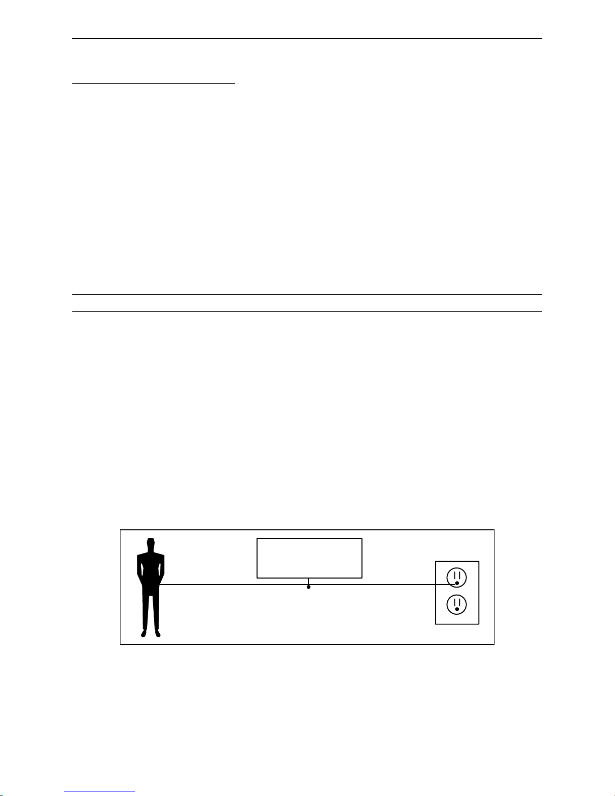
STATIC DISCHARGE PRECAUTIONS
The electronic circuits in the 3000 are completely protected from static electricity damage only while the bed
is assembled. It is extremely important that all service personnel always use adequate static protection when
servicing the electronic systems of the 3000. Whenever you are touching wires, you should be using static
protection.
Static Protection Equipment
The necessary equipment for proper static protection is:
1 static wrist strap; 3M part number 2214 or equivalent,
1 grounding plug; 3M part number 61038 or equivalent,
1 test lead with a banana plug on one end and an alligator clip on the other; Smith part number
N132B699 or equivalent.
CAUTION
All electronic service parts will be shipped in static shielding bags. Do not open the bags until you have completed steps 2 and 3 of the following procedure. Do not place unprotected circuit boards on the floor . All circuit
boards to be returned to Stryker Medical should be shipped in the static shielding bags the new boards were
shipped in.
Static Protection Procedure
1. Unplug the power cord from the wall receptacle.
2. Insert the grounding plug into a properly grounded hospital grade wall receptacle. Plug the banana plug
of the test lead into the receptacle on the grounding plug. Connect the alligator clip on the other end of
the test lead to a ground point on the bed.
3. Place the static control wrist strap on your wrist. Connect the alligator clip at the other end of the wrist strap
cord to a ground point on the bed.
BED
GROUNDING DIAGRAM
10
Page 11

Chapter One – Introduction
1.3 WARRANTY
Limited Warranty:
Stryker Patient Care Division, a division of Stryker Corporation, warrants to the original purchaser that the
MPS 3000 Bed should be free from defects in material and workmanship for a period of two (2) years after
date of delivery. Stryker’s obligation under this warranty is expressly limited to supplying replacement parts
for, or replacing, at its option, any product which is, in the sole discretion of Stryker, found to be defective.
Stryker warrants to the original purchaser that the frame and welds on its beds will be free from structural
defects for as long as the original purchaser owns the bed. If requested by Stryker, products or parts for which
a warranty claim is made shall be returned prepaid to Stryker’s factory. Any improper use or any alteration
or repair by others in such manner as in Stryker’s judgement affects the product materially and adversely shall
void this warranty. No employee or representative of Stryker is authorized to change this warranty in any way.
This statement constitutes Stryker’s entire warranty with respect to the aforesaid equipment. STRYKER
MAKES NO OTHER WARRANTY OR REPRESENTATION, EITHER EXPRESSED OR IMPLIED, EXCEPT
AS SET FORTH HEREIN. THERE IS NO WARRANTY OF MERCHANTABILITY AND THERE ARE NO
WARRANTIES OF FITNESS FOR ANY PARTICULAR PURPOSE. IN NO EVENT SHALL STRYKER BE
LIABLE HEREUNDER FOR INCIDENTAL OR CONSEQUENTIAL DAMAGES ARISING FROM OR IN ANY
MANNER RELATED TO SALES OR USE OF ANY SUCH EQUIPMENT.
To Obtain Parts and Service:
Stryker products are supported by a nationwide network of dedicated Stryker Field Service Representatives.
These representatives are factory trained, available locally, and carry a substantial spare parts inventory to
minimize repair time. Simply call your local representative, or call Stryker Customer Service at (800)
327–0770.
Supplemental Warranty Coverage:
Stryker has developed a comprehensive program of extended warranty options designed to keep your equipment operating at peak performance at the same time it eliminates unexpected costs. We recommend that
these programs be activated before the expiration of the new product warranty to eliminate the potential of
additional equipment upgrade charges. Stryker offers the following Supplemental Warranties:
Extended (Parts and Labor)
All replacement parts (excluding mattresses and consumable items)
Labor and travel for all scheduled and unscheduled calls
Biannual Preventative Maintenance Inspections and repairs
JCAHO paperwork for preventative maintenance
Priority Emergency Service
Standard (Labor Only):
Labor and travel for all scheduled and unscheduled calls
Biannual Preventative Maintenance Inspections and repairs
JCAHO paperwork for preventative maintenance
Priority Emergency Service
Basic (Parts Only):
All replacement parts (excluding mattresses and consumable items)
Priority Emergency Service
Please call your local representative, or call (800) 327–0770 for further information
11
Page 12

Chapter One – Introduction
1.3 WARRANTY (CONTINUED)
Return Authorization:
Merchandise cannot be returned without approval from the Stryker Customer Service Department. An authorization number will be provided which must be printed on the returned merchandise. Stryker reserves the
right to charge shipping and restocking fees on returned items.
SPECIAL, MODIFIED, OR DISCONTINUED ITEMS NOT SUBJECT TO RETURN.
Damaged Merchandise:
ICC Regulations require that claims for damaged merchandise must be made with the carrier within fifteen
(15) days of receipt of merchandise. DO NOT ACCEPT DAMAGED SHIPMENTS UNLESS SUCH DAMAGE
IS NOTED ON THE DELIVERY RECEIPT AT THE TIME OF RECEIPT. Stryker Customer Service must be
notified immediately. Stryker will aid the customer in filing a freight claim with the appropriate carrier for damages incurred. Claim will be limited in amount to the actual replacement cost. In the event that this information
is not received by Stryker within the fifteen (15) day period following the delivery of the merchandise, or the
damage was not noted on the delivery receipt at the time of receipt, the customer will be responsible for payment of the original invoice in full.
Claims for any short shipment must be made within thirty (30) days of invoice.
12
Page 13

Chapter One – Introduction
1.4 RECOMMENDED PARTS KITS
MPS 3000 STARTER PACKAGE
Sensor Coil Cord Kit p/n 3000–200–741
Power Coil Cord Kit p/n 3000–200–743
Power Cord Kit p/n 3000–300–737
Lift Motor Kit p/n 3000–200–727
Fowler Motor Kit (includes clutch) p/n 3000–300–703
Gatch Motor Kit p/n 3000–300–711
Load Cell Kit (optional equipment) p/n 3000–307–701
Weigh CPU (optional equipment) p/n 3000–307–959
Caster Assembly p/n 3000–200–30 and 3000–200–16 (steer)
Main CPU Board Assembly p/n 3000–300–941
Junction Power Board Assembly p/n 3000–300–961
Interface Board Assembly p/n 3000–303–933
Lift Potentiometer Kit (Head) p/n 3000–200–929
Lift Potentiometer Kit (Foot) p/n 3000–200–731
Single Tube of Grease p/n 3000–200–700
Hardware Kit (reference p/n below)
MPS 3000 HARDWARE KIT – P/N 3000–000–700
Fuses (Variety)
Cover Fasteners (Variety) – siderails, bellows, lift covers, litter access, inner
shield
Snap Rings (Variety)
Sheet Metal Screws (Variety)
Cable Clamps (Variety)
Roll Pins (Variety)
Cotter Pins (Variety)
Steer Cable Retainer with Set Screw
Brake Pedal Bolt
Siderail Module Screws
Push Retaining Ring
Micro Switch (motion interrupt, brake)
13
Page 14

Chapter One – Introduction
1.5 REPLACEMENT PARTS KITS
BASE KITS
1. Steer Cable Kit – p/n 3000–200–701
2. Complete Lift Assembly Kit – p/n 3000–200–705
3. Idler Gear Kit – p/n 3000–200–707
4. Manual Idler Gear Kit – p/n 3000–200–709
5. Motor Pinion Gear Kit – p/n 3000–200–711
6. Outer Screw Kit – p/n 3000–200–713
7. Inner Screw Kit – p/n 3000–200–715
8. Single Tube of Grease – p/n 3000–200–700
9. Lift Motor Isolation Plate Kit – p/n 3000–200–723
10. Lift Motor Coupler Kit – p/n 3000–200–705
11. Lift Motor Kit – p/n 3000–200–727
12. Lift Potentiometer Kit (Head) – p/n 3000–200–729
13. Lift Potentiometer Kit (Foot) – p/n 3000–200–731
14. Brake Cam Kit – p/n 3000–200–733
15. Brake Sensor Switch Kit – p/n 3000–200–735
16. Brake Pedal Kit – p/n 3000–200–737
17. Steer Pedal Kit – p/n 3000–200–703
18. Upper Lift Cover Kit (Head) – p/n 3000–200–739
19. Upper Lift Cover Kit (Foot) – p/n 3000–200–749
20. Sensor Coil Cord Kit – p/n 3000–200–741
21. Power Coil Cord Kit – p/n 3000–200–743
22. Lift Capacitor Kit – p/n 3000–200–745
23. Lower Lift Cover Kit (Head or Foot) – p/n 3000–200–747
24. Manual Override Shaft Kit – p/n 3000–200–751
LITTER KITS
25. Load Cell Kit (Optional Equipment) – p/n 3000–307–701
26. Fowler Motor Kit (Includes Clutch) – p/n 3000–300–703
27. Fowler Decoupler/Isolator Kit – p/n 3000–300–705
28. Fowler Ball Screw Kit – p/n 3000–300–707
29. Fowler/Gatch Cam & Cam Guide Kit – p/n 3000–300–709
30. Gatch Motor Kit – p/n 3000–300–711
31. Gatch Coupler Kit – p/n 3000–300–713
32. Gatch Drive Screw Kit – p/n 3000–300–715
33. Translation Cable Kit – p/n 3000–300–717
34. CPR Handle Kit (Right) – p/n 3000–300–719
35. CPR Handle Kit (Left) – p/n 3000–300–739
36. Litter Electrical Cover #2 Kit – p/n 3000–300–721
14
Page 15

Chapter One – Introduction
1.5 REPLACEMENT PARTS KITS (CONTINUED)
LITTER KITS (CONTINUED)
37. Litter Mid Cover #5 Kit – p/n 3000–300–723
38. Fowler Motor Cover #4 Kit – p/n 3000–300–725
39. Head End Litter Cover #3 Kit – p/n 3000–300–727
40. Foot End Litter Cover #1 Kit – p/n 3000–300–729
41. Fowler Capactior Kit – p/n 3000–300–731
42. Gatch Capacitor Kit – p/n 3000–300–733
43. Litter Hinge Cover Kit – p/n 3000–300–735
44. Power Cord Kit – p/n 3000–300–737
SIDERAIL KITS
45. Foot End Siderail Kit (Right) – p/n 3000–400–701
46. Foot End Siderail Kit (Left) – p/n 3000–400–703
47. Head End Siderail Kit (Right) – p/n 3000–400–705
48. Head End Siderail Kit (Left) – p/n 3000–400–707
49. Siderail Head/Knee Module Kit (Inside/Right) – p/n 3000–400–709
50. Siderail Head/Knee Module Kit (Inside/Left) – p/n 3000–400–711
51. Siderail Head/Knee Module Kit (Outside/Right) – p/n 3000–409–713
52. Siderail Head/Knee Module Kit (Outside/Left) – p/n 3000–409–715
53. Siderail Nurse Call Module Kit (Inside/Right) – p/n 3000–403–717
54. Siderail Nurse Call Module Kit (Inside/Left) – p/n 3000–403–719
55. Siderail Nurse Call Module Kit (Outside/Right) – p/n 3000–403–721
56. Siderail Nurse Call Module Kit (Outside/Left) – p/n 3000–403–723
57. Siderail TV/Radio Module Kit (Inside/Right) – p/n 3000–404–723
58. Siderail TV/Radio Module Kit (Inside/Left) – p/n 3000–404–725
59. Siderail Dynamic Mattress System Module Kit (Inside/Right) – p/n 3000–402–727
60. Siderail Dynamic Mattress System Module Kit (Inside/Left) – p/n 3000–402–729
61. Siderail Lights Module Kit (Inside/Right) – p/n 3000–406–731
62. Siderail Lights Module Kit (Inside/Left) – p/n 3000–406–733
63. Siderail Bed Up/Down Module Kit (Outside/Right) – p/n 3000–400–735
64. Siderail Bed Up/Down Module Kit (Outside/Left) – p/n 3000–400–737
FOOT BOARD KITS
65. Foot Board Bed Position/Lockout Module Kit – p/n 3000–500–701
66. Foot Board Head/Knee Module Kit – p/n 3000–501–703
67. Foot Board Bed Exit System Module Kit – p/n 3000–508–705
68. Foot Board Dynamic Mattress System Module Kit – p/n 3000–502–707
69. Foot Board Scale Module Kit – p/n 3000–507–709
70. Foot Board Lid Kit – p/n 3000–500–711
71. C–Bumper Kit (Foot or Head Board) – p/n 3000–500–713
15
Page 16

Chapter One – Introduction
1.6 CLEANING
Hand wash all surfaces of the bed with warm water and mild detergent. Dry thoroughly.
CAUTION
Quaternary Germicidal Disinfectants, used as directed, and/or Chlorine Bleach products, typically 5.25% So dium Hypochlorite in dilutions ranging between 1 part bleach to 100 parts water, and 2 parts bleach to 100
parts water are not considered mild detergents. THESE PRODUCTS ARE CORROSIVE IN NATURE AND
MAY CAUSE DAMAGE TO YOUR BED IF USED IMPROPERLY. If these types of products are used to clean
Stryker patient care equipment, measures must be taken to insure the beds are wiped with clean water and
thoroughly dried following cleaning. Failure to properly rinse and dry the beds will leave a corrosive residue
on the surface of the bed, possibly causing premature corrosion of critical components. Failure to follow the
above directions when using these types of cleaners may void this product’s warranty.
CAUTION
Do not steam clean or hose off the MPS 3000 Bed. Do not immerse any part of the bed. Some of the internal
parts of the bed are electric and may be damaged by exposure to water.
16
Page 17

Chapter One – Introduction
1.7 PREVENTATIVE MAINTENANCE
BIANNUAL CHECKLIST
All fasteners secure (reference all assembly prints)
All casters lock with brake pedal engaged
”Brake Not Set” LED (on foot board) blinks when brakes are not engaged
Locking steer caster engages and disengages properly
Siderails move, latch and stow properly
CPR release working properly
Foot prop intact and working properly
I.V. pole working properly
Foley bag hooks intact
Optional chart rack intact and working properly
Optional CPR board not cracked or damaged and stores properly
No cracks or splits in head and foot boards
No rips or cracks in mattress cover
All functions on head end siderails working properly (including LED’s)
All functions on footboard working properly (including LED’s)
Motion Interrupt switches working properly
Optional night light working properly
Power cord not frayed
No cables worn or pinched
All electrical connections tight
All grounds secure to the frame
Ground impedence not more than 100 milliohms
Current leakage not more than 100 microamps
Apply grease to litter grease points
Bed Serial No. ______________
______________
______________
______________
______________
______________
______________
______________
______________
______________
17
Page 18

Chapter Two – MPS Operations
2.1 SET–UP PROCEDURES
It is important that the MPS 3000 Bed is working properly before it is put into service. The following list will
help assure that each part of the bed is tested.
Plug the bed into a properly grounded, hospital grade wall receptacle and assure the ”Power” LED
light at the foot end of the bed comes on.
WARNING
The 3000 is equipped with a hospital grade plug for protection against shock hazard. It must be plugged directly into a properly grounded three–prong receptacle. Grounding reliability can be achieved only when a
hospital grade receptacle is used.
Plug the optional interface cable into the 37 pin connector under the litter frame at the head end of
the bed, and into the ”Patient Station”, ”Head Wall”, ”Docker Station”, or equivalent (whichever applies).
Assure the siderails raise, lower and store smoothly and lock in the up and intermediate positions
(page 28).
Assure that all four casters lock when the brake pedal is engaged (page 20).
NOTE
Assure that the ”Brake Not Set” LEDs located on the outside of the head end siderails and on the foot board
control panel come on when the brakes are disengaged.
Run through each function on the foot end control panel to assure that each function is working prop-
erly (page 25 & 26).
Run through each function on both head end siderails to assure that each is working properly (page
29 & 30).
Activate the motion stop system to assure it is functioning properly: press and hold down the BED
DOWN key. As the bed lowers, lift up on each corner of the motion interrupt pan individually and assure the downward motion stops each time. Release the pan and allow the downward motion to continue.
NOTE
The bed’s upward motion or other functions are not disrupted by the motion stop system.
If any problems are found during bed set–up, contact Stryker Customer Service at 800–327–0770.
Damaged Merchandise
ICC Regulations require that claims for damaged merchandise must be made with the carrier within fifteen
(15) days of receipt of merchandise. DO NOT ACCEPT DAMAGED SHIPMENTS UNLESS SUCH DAMAGE
IS NOTED ON THE DELIVERY RECEIPT AT THE TIME OF RECEIPT. Stryker Customer Service must be
notified immediately. Stryker will aid the customer in filing a freight claim with the appropriate carrier for damages incurred. Claim will be limited in amount to the actual replacement cost. In the event that this information
is not received by Stryker within the fifteen (15) day period following the delivery of the merchandise, or the
damage was not noted on the delivery receipt at the time of receipt, the customer will be responsible for payment of the original invoice in full.
Claims for any short shipment must be made within thirty (30) days of invoice.
18
Page 19

Chapter Two – MPS Operations
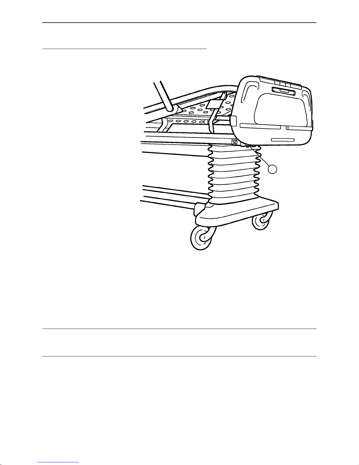
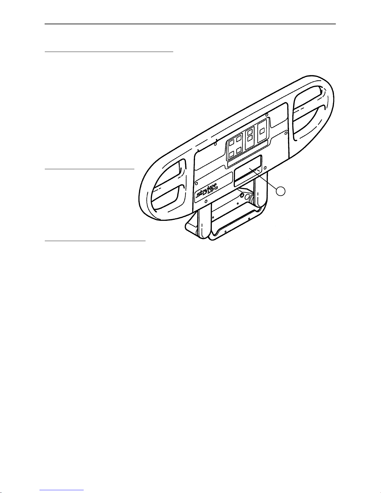
2.2 BED ILLUSTRATION
HEAD END
PATIENT’S
RIGHT
Steer
Pedal
I.V. and
Fracture Frame
Mount
CPR Release
Handle
Motion
Interrupt
Pan
Foley Bag Hooks
(Standard)
Siderail Release
Handle
Brake Pedal
PATIENT’S
LEFT
Foley Bag Hook
(Isolated)
(Optional Equip.)
Night
Light
I.V. and
Fracture Frame
Mount
Footboard
Control
Panel
Chart
Rack
(Optional Equip.)
FOOT END
19
Page 20

Chapter Two – MPS Operations
2.3 BASE OPERATION GUIDE
BRAKE PEDAL OPERATION
WARNING
Before putting a patient on the bed, be sure the brakes are fully engaged. Failure to set the brakes may allow
the bed to move, causing patient injury.
To activate the brakes, push down once on the pedal
identified by the label at right (located at both sides of
the bed). To disengage, push down once.
NOTE
There are LED lights on the outside of the head end siderails and on the foot end control panel that will blink
when the brakes are not engaged only if the bed is plugged into a wall socket (see pages 27 & 30). The brakes
will still operate properly when the bed is not plugged in.
STEER PEDAL OPERATION
The purpose of the steer caster is to help guide the bed along a straight line and to help with pivoting at corners
when the bed is moved.
To activate the steer caster, move the pedal located
at the head end of the bed to your left as shown on
the label.
NOTE
For proper ”tracking” of the steer caster, push the bed approximately 10 feet to allow the wheels to face the
direction of travel before engaging the steer pedal. If this is not done, proper ”tracking” will not occur and the
bed will be difficult to steer.
20
Page 21
Chapter Two – MPS Operations
2.4 LITTER OPERATION GUIDE
CPR EMERGENCY RELEASE USAGE
When quick access to the patient is needed, and the Fowler is raised, squeeze one of the two red release
handles (see illustration, page 19) and the Fowler can be lowered to a flat position.
NOTE
The handle can be released at any time to stop lowering the Fowler.
FOLEY BAG HOOKS USAGE, STANDARD AND ISOLATED (Isolated Optional Equipment)
The standard Foley bag hooks are found at two locations on both sides of the bed, under the frame rail below
the seat section and the extreme foot end of the bed.
NOTE
The patient weight reading on the bed scale system will be affected by using the standard Foley bag hooks.
The optional isolated Foley bag hooks are located under the litter frame at the top of the foot end bellows.
CAUTION
The Foley bag hooks move when the Fowler is raised or lowered. Fowler motion must be locked out when
using these hooks, and great care must be taken to avoid inadvertent movement of the hooks.
NOTE
The patient weight reading on the bed scale system will not be affected by usage of the isolated Foley bag
hooks.
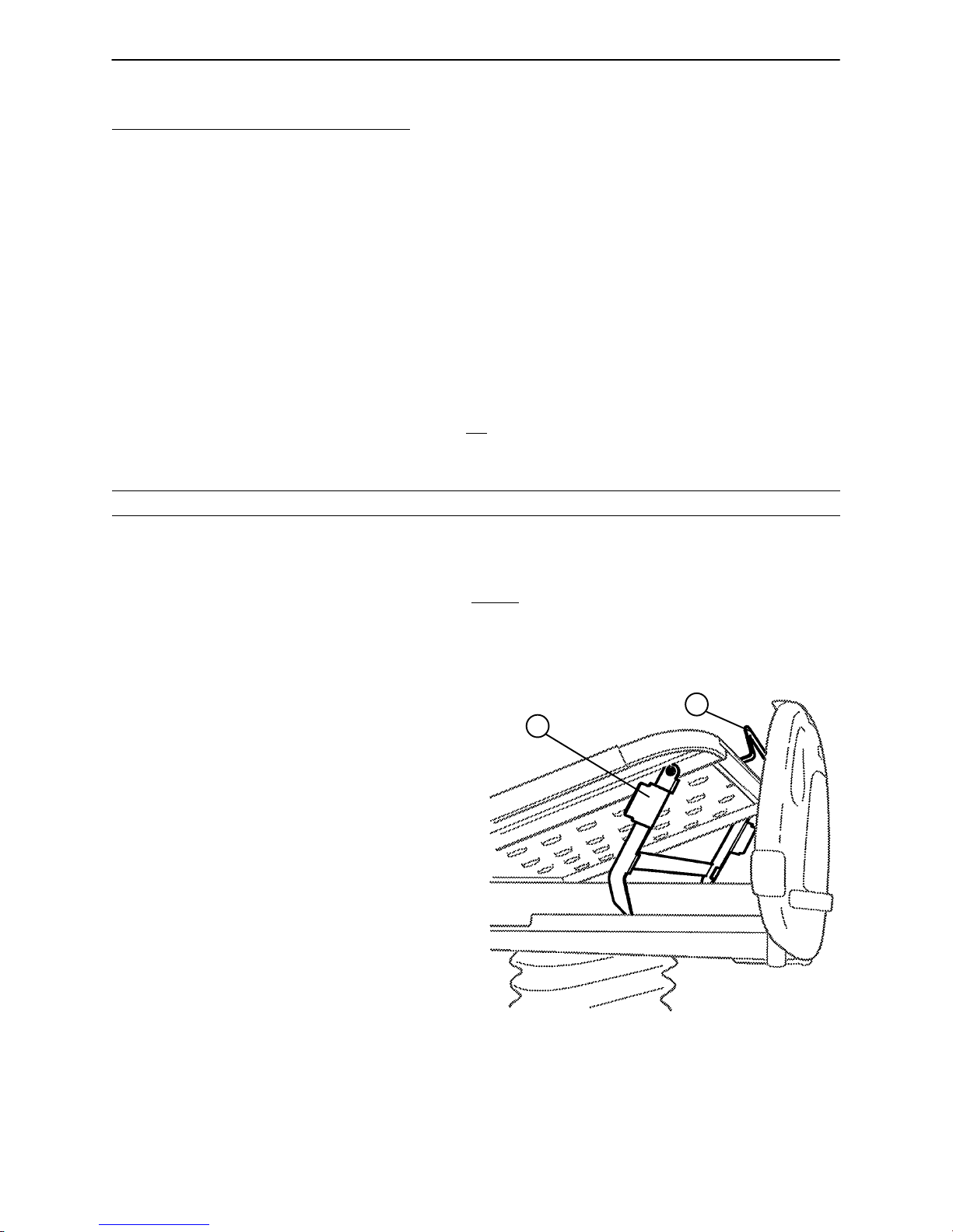
FOOT PROP USAGE
A
B
To prop the foot end of the Knee Gatch up, grasp
the handle (A) at the end of the Knee Gatch and
lift upward, allowing the latch arm to engage at the
desired height. To release the prop, lift up slightly
on the handle (A) and swing the foot prop handle
(B) toward the head end of the bed to disengage
the hinge and allow the foot end to lower.
FRACTURE FRAME USAGE
A standard fracture frame can be mounted on the bed using the I.V. sockets located on all four corners of
the bed. I.V. poles can be used in conjunction with a fracture frame if I. V . pole adaptor sockets are purchased.
FOOT END
21
Page 22
Chapter Two – MPS Operations
2.4 LITTER OPERATION GUIDE (CONTINUED)
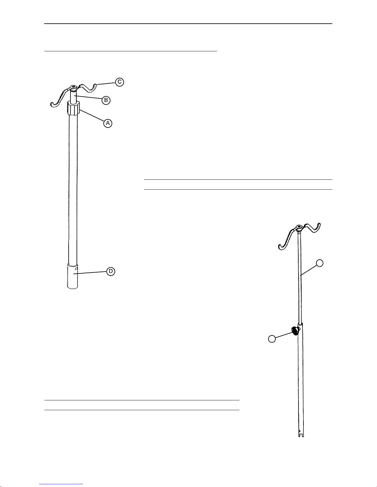
I.V. POLES
To use the Permanently Attached I.V. pole (optional equipment):
1. Lift and pivot the pole from the storage position and push down
until it is locked into receptacle (D).
2. To raise the height of the pole, turn the lock actuator (A) counter–
clockwise and pull up on the telescoping portion (B) of the pole to
raise it to the desired height.
3. Turn the lock actuator (A) clockwise to lock the telescoping portion
in place.
4. Rotate the I.V. hangers (C) to desired position and hang I.V. bags.
CAUTION
The maximum weight capacity of the I.V. pole is 40 pounds.
To use the ”Removable” I.V. pole:
1. Remove the pole from its storage position located at the foot end of the
bed, under the foot board.
2. Install the pole at any of the six receptacles on the bed top (located on
all four corners of the bed and halfway down the bed, on both sides.)
3. To raise the height of the pole, turn knob (A) counterclockwise and pull
up on the telescoping portion (B) of the pole and raise it to the desired
height.
4. Turn knob (A) clockwise to tighten the telescoping portion in place.
CAUTION
The maximum weight capacity of the I.V. pole is 40 pounds.
B
A
22
Page 23
Chapter Two – MPS Operations
2.4 LITTER OPERATION GUIDE (CONTINUED)
NIGHT LIGHT USAGE (Optional Equipment)
The bed may be equipped with
an optional night light (A) that will
illuminate the floor area around
the bed. The light has three set–
tings: LOW–OFF–HIGH.
A
FOOT END
PATIENT RESTRAINT STRAP LOCATIONS
The bed is equipped with 12 separate locations for installing patient restraint straps. The ”cutouts” in the bed
top are located directly across from each other (on both sides of the bed). When using restraint straps, attach
only to these locations. Never attach to mattress or bed rails.
WARNING
Restraints should be used only under the supervision of a licensed health care provider. Improperly adjusted
or improperly located restraint straps can cause serious injury to a patient.
23
Page 24
Chapter Two – MPS Operations
2.5 FOOT BOARD/HEAD BOARD OPERATION GUIDE
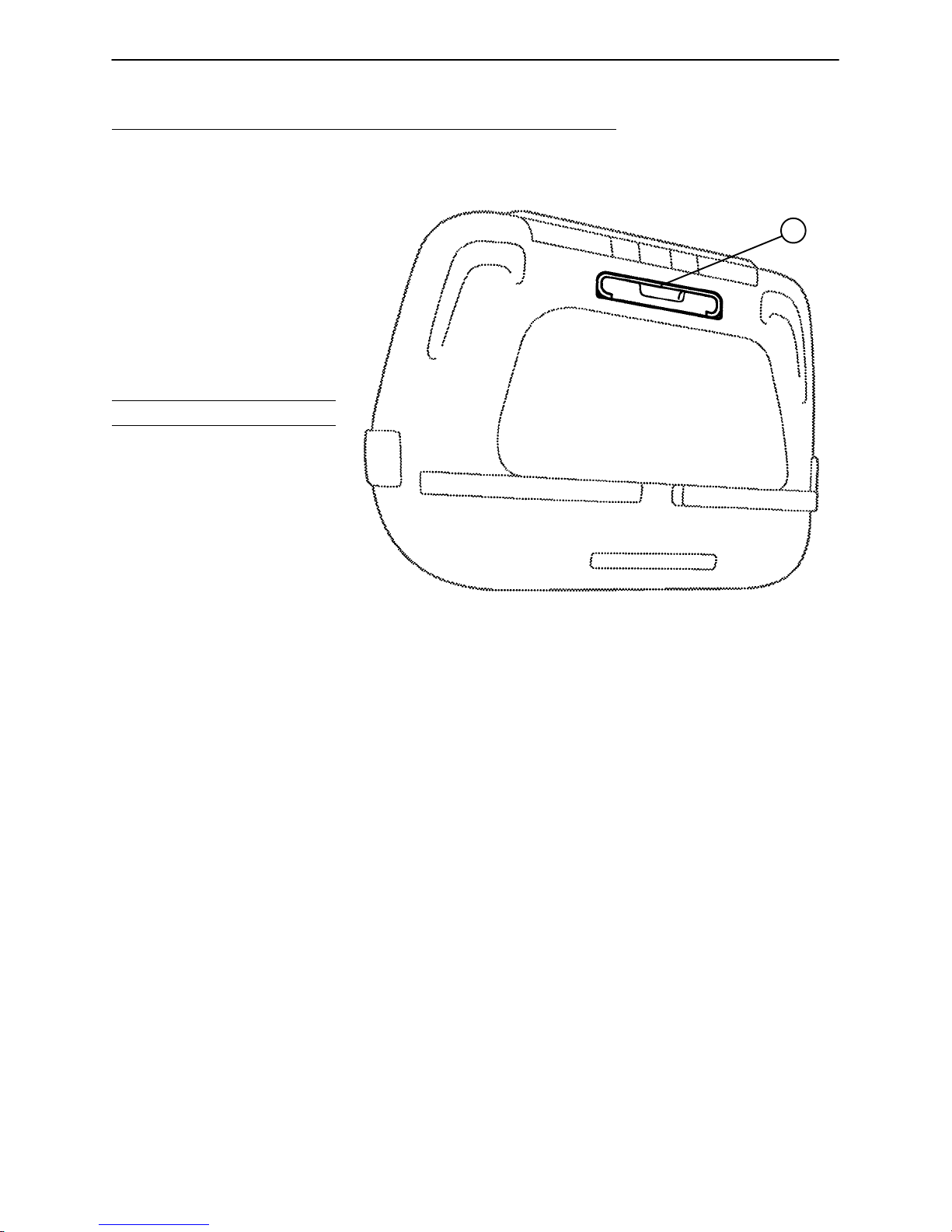
CHART RACK USAGE (Optional Equipment)
If the bed is equipped with the optional
chart rack, it is located on the foot
board. To use, pull handle rod (A)
downward. To store, push the handle
back to its storage position until it
locks in place.
CAUTION
Do not use handle rod (A) as a
device for pulling the bed. Doing
so may cause damage to the chart
rack and foot board.
A
FOOT END
CPR BOARD USAGE (Optional Equipment)
If the bed is equipped with the optional CPR board, it is stored on the bed’s head board. To remove, pull
away from the head board and lift out of storage position. If the CPR board option was not purchased,
the head board can be removed and used as an emergency CPR board.
24
Page 25
Chapter Two – MPS Operations
2.5 FOOT BOARD/HEAD BOARD OPERATION GUIDE (CONTINUED)
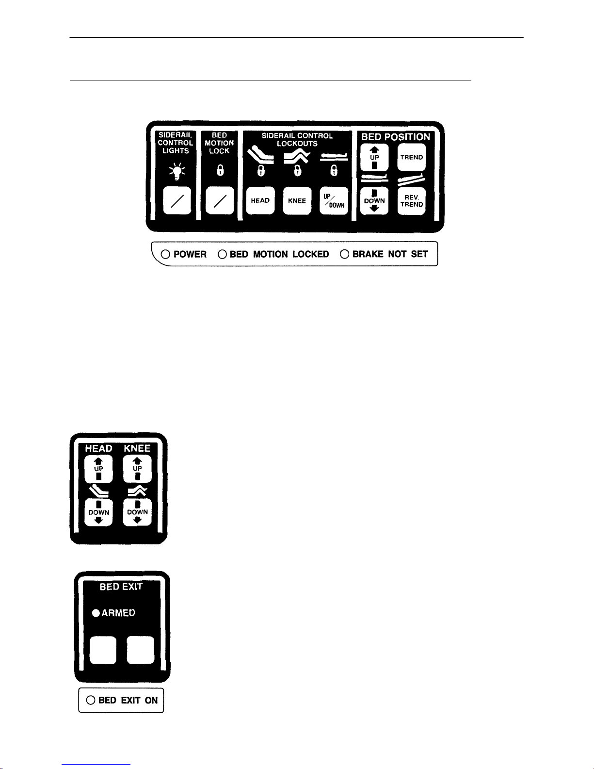
FOOT BOARD CONTROL PANEL GUIDE
8
ON
OFF
1234567
ON
OFF
9
1. Push to turn on siderail control panel lights. Push again to turn off (see page 28).
2. Push to lock out all bed motions. Push again to unlock (see page 35).
3. Push to lock out Fowler. Push again to unlock (see page 35).
4. Push to lock out Knee Gatch. Push again to unlock (see page 35).
5. Push to lock out bed height movement. Push again to unlock (see page 35).
6. Push to raise bed height.
7. Push to lower bed height.
8. Push to lower head end/raise foot end of bed (Trendelenberg position).
9. Push to lower foot end/raise head end of bed (Reverse Trendelenberg position).
1. Push to raise Fowler.
12
2. Push to raise Knee Gatch.
3. Push to lower Fowler.
4. Push to lower Knee Gatch.
34
This panel is optional equipment.
ARM DISARM
12
1. Push to activate Bed Exit function (see page 35).
2. Push to deactivate Bed Exit function (see page 35).
This panel is optional equipment.
25
Page 26
Chapter Two – MPS Operations
2.5 FOOT BOARD/HEAD BOARD OPERATION GUIDE (CONTINUED)
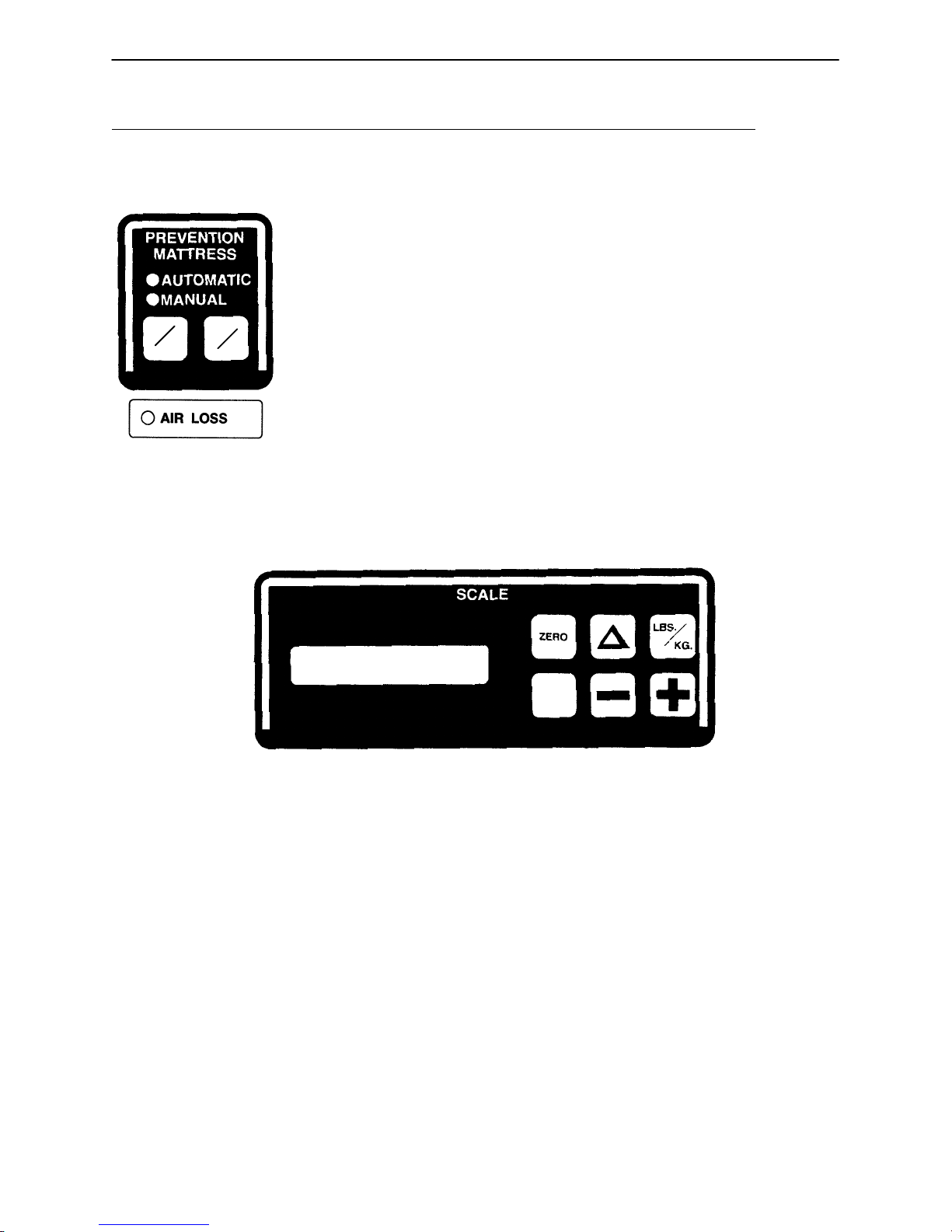
FOOT BOARD CONTROL PANEL GUIDE (Continued)
1. Push to turn the Dynamic Mattress system on or off (see page 35).
2. Push to activate automatic or manual modes (see page 35).
This panel is optional equipment.
1
ON
OFF
AUTO
MAN
2
1
23 4
SCALE
ON
567
1. LCD – displays patient weight.
2. Push to zero bed (see page 31 & 33).
3. Push when changing equipment on the bed (see page 31 & 33).
4. Push to change weight from pounds to kilograms or back (see page 32 & 33).
5. Push to turn weigh system on (see page 31 – 33).
6. Push to decrease numerical value of displayed weight (see page 32 & 34).
7. Push to increase numerical value of displayed weight (see page 32 & 34).
This panel is optional equipment.
NOTE
See page 27 for explanation of LED’s.
26
Page 27

Chapter Two – MPS Operations
2.5 FOOT BOARD/HEAD BOARD OPERATION GUIDE (CONTINUED)
LED DISPLAY PANEL GUIDE
The LED Display Panel is located at the foot end of the bed, under the Control Panel.
POWER BED MOTION LOCKED BRAKE NOT SET BED EXIT ON AIR LOSS
”POWER” – will light when the bed is plugged into the wall receptacle.
”BED MOTION LOCKED” – will light when the Bed Motion Lock has been activated.
”BRAKE NOT SET” – will blink when the brakes have not been set.
”BED EXIT ON” – will light when the Bed Exit function has been activated (optional equipment).
”AIR LOSS” – will light when there is a possible air leak in the Dynamic Mattress System (optional equipment).
27
Page 28
Chapter Two – MPS Operations
2.6 SIDERAIL OPERATION GUIDE
POSITIONING SIDERAILS
NOTE
The siderails can be locked at two heights (intermediate & full).
The siderails can be tucked away under the bed when not in use.
To remove the rail from the tucked position, grasp at the top of the
rail and pull outward.
To engage the siderail, grasp the rail and push it
upward until it rests in the ”intermediate” position.
To continue to the full height, pull the brown
release handle (A) until full height is
reached.
WARNING
Be sure rail is locked securely
into position. Siderails are not
intended to keep patients from
exiting the bed. They are
designed to keep a patient
from inadvertently rolling off the
bed. Always keep siderails in full–up
position when a patient is in the bed.
A
To disengage the rail, pull the brown release handle and pivot rail down to desired height. Tuck away siderails
by pushing the rails under the bed. Rails must be in the full down position before they can be tucked.
SIDERAIL CONTROL PANEL LIGHTS
The bed is equipped with lights that will illuminate the head end siderail control panel and can be activated
at the foot board control panel (see control panel guide page 25).
28
Page 29
Chapter Two – MPS Operations
2.6 SIDERAIL OPERATION GUIDE (CONTINUED)
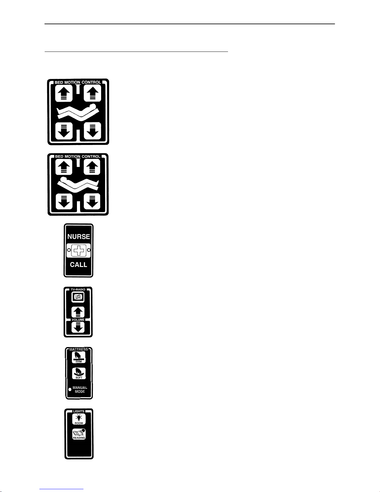
INSIDE SIDERAIL FUNCTION GUIDE
12
34
12
34
(Patient’s Right Rail)
1. Push to raise Knee Gatch.
2. Push to raise Fowler.
3. Push to lower Knee Gatch.
4. Push to lower Fowler.
(Patient’s Left Rail)
1. Push to raise Fowler.
2. Push to raise Knee Gatch.
3. Push to lower Fowler.
4. Push to lower Knee Gatch.
Push to activate Nurse Call.
NOTE
Yellow LED will light when button is pushed. Red LED will light with
Nurse Station acknowledgment.
This panel is optional equipment.
Push to turn TV or radio on and to select a channel.
Push to increase volume.
Push to decrease volume.
This panel is optional equipment.
Push to increase firmness of mattress.
Push to decrease firmness of mattress.
LED will light when the ”Manual” mode has been set at the foot
end of the bed.
This panel is optional equipment.
Push to turn the room light on.
Push to turn the bed overhead light on.
This panel is optional equipment.
29
Page 30
Chapter Two – MPS Operations
2.6 SIDERAIL OPERATION GUIDE (CONTINUED)
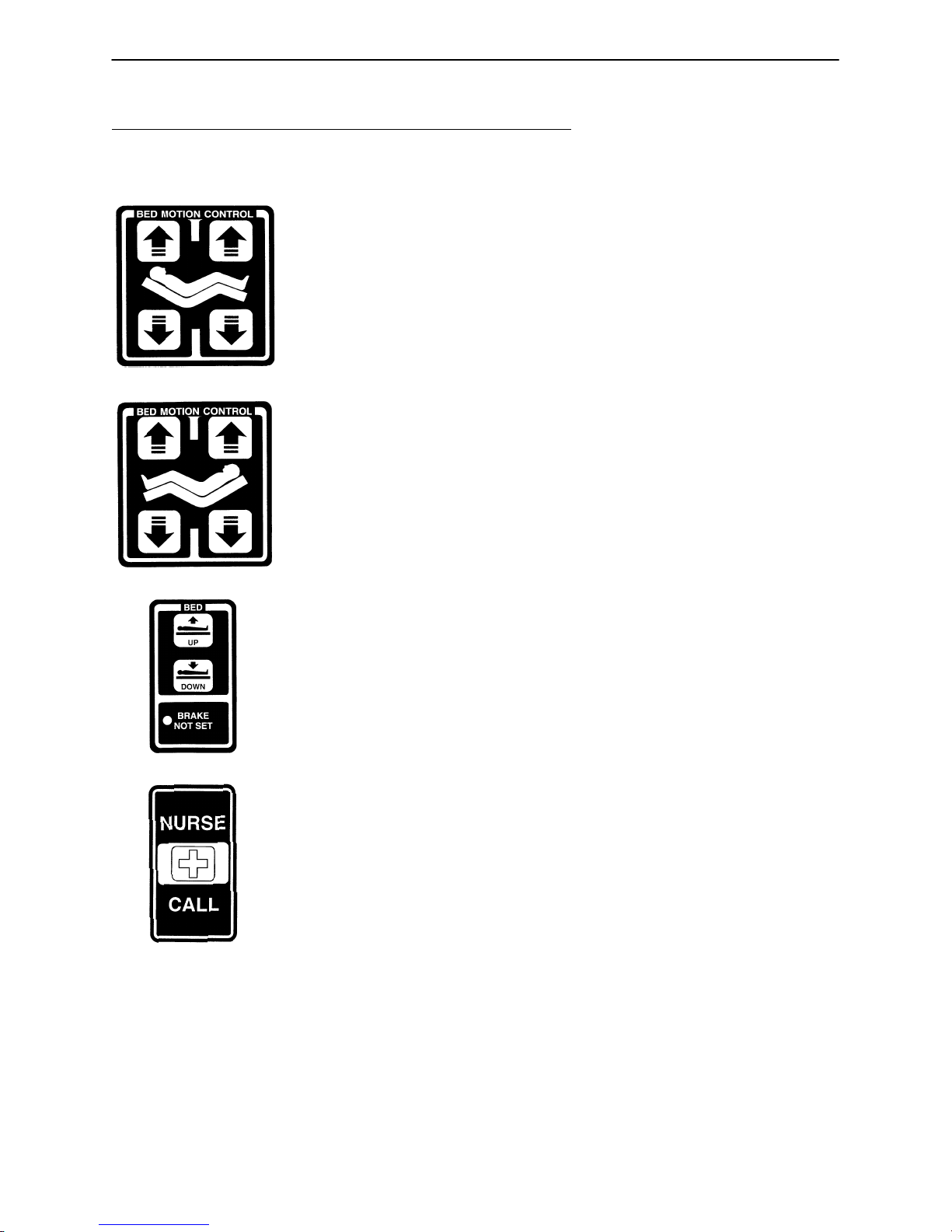
OUTSIDE SIDERAIL FUNCTION GUIDE
12
3
12
34
4
(Patient’s Right Rail)
1. Push to raise Fowler.
2. Push to raise Knee Gatch.
3. Push to lower Fowler.
4. Push to lower Knee Gatch.
This panel is optional equipment.
(Patient’s Left Rail)
1. Push to raise Knee Gatch.
2. Push to raise Fowler.
3. Push to lower Knee Gatch.
4. Push to lower Fowler.
This panel is optional equipment.
Push to raise bed height.
Push to lower bed height.
LED will blink when the brakes are not set.
Push to activate Nurse Call.
This panel is optional equipment.
30
Page 31

Chapter Two – MPS Operations
2.7 WEIGH SYSTEM OPERATION GUIDE
WEIGH SYSTEM USAGE
OPERATING THE SCALE BEFORE PUTTING A NEW PATIENT IN BED
Prepare bed for patient stay (linens, pillows, etc.).
Press and release ”SCALE ON”. The scale monitor will read:
”WEIGHING”
”XXX.X LB”
Press and hold ”ZERO”. The scale monitor will read:
”HOLD TO ZERO WT.”
”RELEASE TO ZERO”
Release ”ZERO”. The scale monitor will now read:
”DO NOT TOUCH BED”
”0.0 LB”
The bed is now ready for the patient.
NOTE
Do not zero the bed while a patient is in bed. If this should occur, remove the patient and zero the bed.
OPERATING THE SCALE IF PATIENT IS ALREADY IN BED
If it is necessary to add or remove special equipment (monitors, pumps, etc.) during the patient’s
stay, press and release ”SCALE ON” to activate the weigh system. After the scale monitor reads
”XXX.X LB”, press and hold . The scale monitor will read:
”HOLD TO START”
”RELEASE TO START”
Release . The scale monitor will read:
”DO NOT TOUCH BED”
”ADD/REMOVE EQUIP”
Add or remove the equipment and press . The scale monitor will read:
”RELEASE TO FIN.”
Release . The scale monitor will read:
The weight displayed will be that of the patient only.
”DO NOT TOUCH BED”
”XXX.X LB”
31
Page 32

Chapter Two – MPS Operations
2.7 WEIGH SYSTEM OPERATION (CONTINUED)
WEIGH SYSTEM USAGE (CONTINUED)
CONVERTING THE PATIENT’S WEIGHT
To convert the patient’s weight from pounds to kilograms, press and release ”SCALE ON” to activate
the weigh system. After the scale monitor reads ”XXX.X LB”, press and release the ”LBS/KGS” button. The scale monitor will read:
”WEIGHT NOW KGS”
”XXX.X KG”
Repeat the procedure to return to pounds. The display will read:
”WEIGHT NOW LBS”
”XXX.X LB”
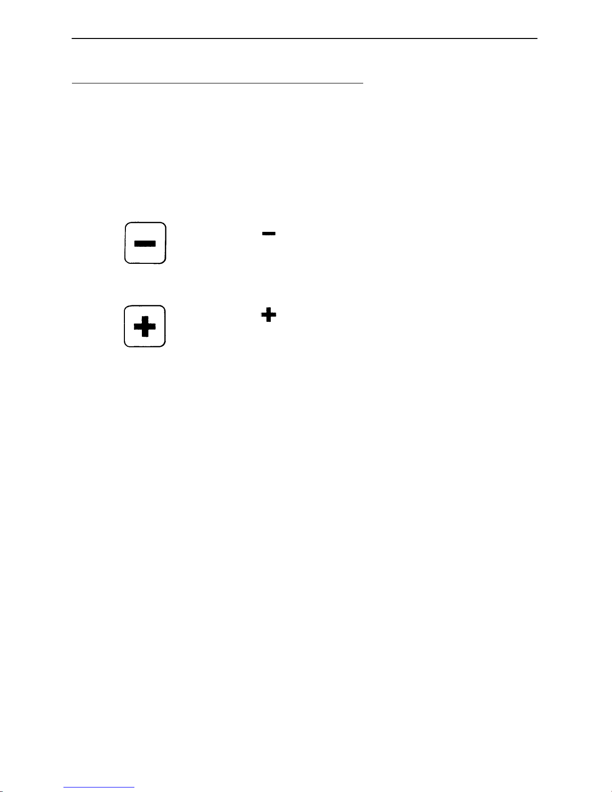
CHANGING THE NUMERICAL VALUE OF DISPLAYED WEIGHT
To decrease the numerical value of the displayed weight, press and hold ”–”. The scale monitor will
read:
”HOLD TO DEC. WT.”
”XXX.X LB”
Hold ”–” until desired value is achieved.
To increase the numerical value of the displayed weight, press and hold ”+”. The scale monitor will
read:
”HOLD TO INC. WT.”
”XXX.X LB”
Hold ”+” until desired value is achieved.
NOTE
The weigh system will shut off approximately one minute after a function has been used, if another function
is not activated. Display light will shut off and display will read ”SCALE OFF”.
The weigh system will retain all patient weight information in its memory even when the scale monitor is off
or when the bed is unplugged from the wall socket.
32
Page 33

Chapter Two – MPS Operations
2.7 WEIGH SYSTEM OPERATION (CONTINUED)
WEIGH SYSTEM CONTROL PANEL GUIDE
SYMBOL ACTION DISPLAY
To prepare bed for new patient:
SCALE
ON
to activate the scale system, begin ”XXX.X LB”
Press and release ”SCALE ON””WEIGHING...”
a new function and to display patient
weight.
ZERO
To add or remove equipment
Press and hold ”ZERO””HOLD TO ZERO WT.”
Release ”ZERO””DO NOT TOUCH BED”
during patient stay without
affecting registered patient
weight:
Press and release ”SCALE ON””WEIGHING...”
Press ”HOLD TO START”
Release ”DO NOT TOUCH BED”
Add or remove equipment.
Press ”RELEASE TO FIN.”
”RELEASE TO ZERO”
”0.0 LB”
”XXX.X LB”
”RELEASE TO START”
”ADD/REMOVE EQUIP.”
To convert the patient’s weight:
LBS.
KG.
Release ”DO NOT TOUCH BED”
”XXX.X LB”
To convert the patient’s weight ”WEIGHT NOW KGS”
to kilograms, press and release ”XXX.X KG”
”LBS./KG.”
Repeat the procedure to return to
pounds.
33
Page 34
Chapter Two – MPS Operations
2.7 WEIGH SYSTEM OPERATION (CONTINUED)
WEIGH SYSTEM CONTROL PANEL GUIDE (CONTINUED)
SYMBOL ACTION DISPLAY
To change the numerical value
of displayed weight:
Press and hold to scroll to ”HOLD TO DEC. WT.”
desired weight. ”XXX.X LB”
Press and hold to scroll to ”HOLD TO INC. WT.”
desired weight. ”XXX.X LB”
34
Page 35

Chapter Two – MPS Operations
2.8 SYSTEM OPERATION GUIDE
”BED EXIT” SYSTEM USAGE (Optional Equipment)
1. Before putting a new patient on the bed: prepare bed for patient stay by adding linens and equipment to
the bed. Press and hold ”DISARM” key for 5 seconds – ”ARMED” light will begin to flash. Release ”DISARM” key and do not touch the bed until ”ARMED” light stops flashing.
2. To arm Bed Exit: place patient on the bed, push ”ARM” key and release (”ARMED” light will come on).
3. To deactivate Bed Exit, push ”DISARM”. The ”ARMED” and ”BED EXIT ON” LED’s will turn off.
NOTE
If the scale system is active, it will switch to ”off” when Bed Exit is armed. Bed Exit will be temporarily disarmed
when the scale system is activated. When the bed is equipped with scales, the scales must be properly
zeroed for the Bed Exit System to function properly (see page 31 for scale system usage instructions).
WARNING
Bed Exit System does not prevent the patient from exiting the bed. It signals when a patient is about to exit.
Adding or subtracting objects from the bed after arming the bed exit system may cause a reduction in the
sensitivity of the bed exit system.
DYNAMIC MATTRESS SYSTEM USAGE (Optional Equipment)
1. Turn the mattress system on using the ”ON/OFF” switch in the ”Prevention Mattress” module on the foot
board control panel (see page 26 for Foot Board Control Panel Guide).
NOTE
Push this switch to turn the system both on and off. The ”AUT OMATIC” or ”MANUAL” LED on the foot board
will be on when the system is active.
2. The system can be set in either ”AUTOMATIC” or ”MANUAL” modes. The ”AUTO/MAN” switch is used
to activate both modes. When Automatic mode is selected, the ”AUTOMATIC” LED on the foot board
control panel will be on. When Manual mode is selected, the ”MANUAL” LED on the foot board control
panel and the ”MANUAL” LED on the inside siderail control panel will be on.
3. When the Automatic mode is selected, the firmness of the mattress will adjust automatically as needed.
When the Manual mode is selected, the firmness of the mattress can be adjusted by the patient or the
hospital clinical staff. The ”FIRM” and ”SOFT” switches are located on the control panels on the inside
of the head end siderails.
NOTE
The ”MANUAL” LED on the inside siderail will blink when the ”FIRM” or ”SOFT” switches are pressed while
in the manual mode.
4. If the ”AIR LOSS” LED is on, an air leak may exist.
FUNCTION LOCKOUT SYSTEM USAGE
1. To lock out the bed movement functions on the siderails and prevent the patient from changing the positioning of the bed, push the ”HEAD”, ”KNEE” and/or ”UP/DOWN” switches in the ”Siderail Control Lockouts”
module on the foot board control panel (see page 25).
NOTE
The foot board controls for these motions are not affected by the lockout switches.
The ”padlock” symbol on the control panel will be lighted when that function is locked out.
2. To lock out the entire bed motion for all switches on the bed, push the ”ON/OFF” switch in the ”Bed Motion
Lock” module on the foot board control panel (see page 25).
35
Page 36

Chapter Three – Troubleshooting
3.1 MECHANICAL TROUBLESHOOTING GUIDE
PROBLEM/SYMPTOM SOLUTION(S)
Brakes engage at one end and release at the other when pedal is activated.
Brakes do not engage when activated.
Brakes do not release.
Steer wheel does not engage when activated.
Steer wheel does not disengage.
Siderail release latch does not engage when activated.
Siderail release latch does not disengage.
CPR release does not disengage when activated. A. Check all applicable hardware and parts align-
Head section (Fowler) drifts down when weight is
added.
Head motor will not run Fowler down electrically –
motor hums momentarily when activated.
A. Brakes out of ”time”: slowly push down on
brake pedal until a spring release noise is heard.
Immediately release pedal then push pedal back
down entirely to set brakes.
B. Check all applicable linkage, hardware and
parts alignment. Replace parts as needed (reference brake assembly drawings, pages 138 & 139).
A. Check all applicable hardware and parts alignment. (See pages 73–75 for steer wheel cable adjustment and replacement.)
A. Check all applicable hardware and parts alignment. (See page 119 for siderail positioning
mechanism replacement.)
ment. (See pages 109 & 110 for CPR adjustments
and repairs.)
A. Back drive clutch has failed. Replace motor
and clutch assembly (see pages 103 & 104).
A. Refer to page 43, steps A & B to assure problem is not electrical. Replace motor and clutch
assembly if problem is mechanical (see pages 103
& 104).
36
Page 37

Chapter Three – Troubleshooting Guides
3.2 MOTION INTERRUPT TROUBLESHOOTING GUIDE
NOTE
Prior to replacing any circuit boards, ensure applicable cables and connections are intact (visually and mechanically). When measuring 110 VAC at any point, use only neutral (white) side of power line as a reference
point. DO NOT use digital ground as a reference point when measuring 110 VAC.
Visually and mechanically check for motion interrupt pan alignment and movement. Observe whether the
pan has been damaged. Any significant alteration in the shape of the pan may affect switch actuation. If the
pan’s shape is altered enough to affect the motion interrupt switches, replace the pan (p/n 3000–300–50) (see
page 95).
PROBLEM/SYMPTOM SOLUTION(S)
Motion interrupt does not disable the movement of
the bed when activated. (Motion of bed may be
prevented if the switch is constantly activated by a
foreign object.)
A. Check individual motion interrupt switches for
actuation and plunger travel. If switches appear to
be dismounted and/or damaged, replace as necessary (see page 96).
B. Using a voltmeter, check for +12 VDC at each
switch. Wire colors represent: red, +12 VDC,
black, ground reference. Replace switches as
necessary.
C. If +12 VDC is present at switches, verify the 2
pin plug from the motor stop cable is plugged into
P2 of the power junction board (p/n 3000–300–
961) (see page 199 for board location).
D. If +12 VDC is not present at the switches,
check connector P14, pin 5 of the litter CPU board
(p/n 3000–300–941). If voltage is not present,
check fuse F1 of the litter CPU board. Replace
fuse if necessary. If fuse is O.K. and voltage is not
present, check for 110 VAC at connector P1, pin
18. If 110 VAC is present, replace litter CPU
board (see page 115). If 110 VAC is not present,
check power junction board (p/n 3000–300–961) at
connector P1, pin 1 for 110 VAC. If voltage is not
present, check fuse F1. Replace as necessary. If
fuse is O.K., and 110 VAC is not present at connector P1, check connector J1, pin 2 for 110 VAC
input from power cord. If 110 VAC is present at
connector J1 but not at connector P1, replace
power junction board as needed (see page 199 for
board location).
37
Page 38

Chapter Three – Troubleshooting Guides
3.3 TRENDELENBERG/REVERSE TRENDELENBERG TROUBLESHOOTING
GUIDE
NOTE
Prior to replacing any boards, ensure applicable cables and connections are intact (visually and mechanically). To check for +5 VDC at various points called out in the troubleshooting, use digital ground as a reference
point (negative side of C18 on CPU litter board). When measuring 1 10 VAC at any point, use only the neutral
(white) side of the power line as a reference point. DO NOT use digital ground as a reference point when
measuring 110 VAC.
Assure the bed motion lock is not activated on the foot board. If bed motion will not unlock, see troubleshooting section 3.9 page 48. If any one part of Trendelenberg/Reverse Trendelenberg motion is not functioning,
see appropriate troubleshooting section (i.e. bed head end lift motor not functioning see section 3.4 page 40).
If the litter is at its lowest height when Trendelenberg or Reverse Trendelenberg is activated, the litter will raise
a few inches until the height is adequate. When this height is achieved, Trend. or Reverse Trend. will proceed.
PROBLEM/SYMPTOM SOLUTION(S)
Trendelenberg does not move into proper position
(head down, foot up).
Reverse Trendelenberg will not move into proper
position (head up, foot down). Note: connector
P2, pin 7 may be used for digital ground reference.
A. Check for +5 VDC at connector P1, pin 6 of the
foot board keyboard (p/n 3000–500–943) (see
page 202 for board location). If voltage is present,
use a voltmeter and verify switches are O.K. If
switches are defective, replace board.
B. Check foot board IFC (p/n 3000–500–955) for
+5 VDC at connector P2, pin 6 (see page 202 for
board location). If voltage is not present, check for
+8 VDC at connector P3, pin 5. If +8 VDC is present and +5 VDC is not present, replace foot board
IFC. If +8 VDC is not present, disconnect connector P3 and check for voltage at the cable connector. If +8 VDC is present at the cable but not at
the board, replace foot board IFC.
C. If Trend./Rev. Trend. motion is still uncontrollable, check the litter CPU board (p/n 3000–300–
941) for +8 VDC at connector P9, pin 5 (see page
199 for board location). If voltage is not present,
check fuse F1. If fuse is O.K. and the problem still
exists, check for 110 VAC at connector P1, pin 18.
If 110 VAC is present, replace litter CPU board. If
110 VAC is not present, check power junction
board (p/n 3000–300–961) at connector P1, pin 1
for 110 VAC. If voltage is not present, check fuse
F1. Replace fuse as necessary. If fuse is O.K.
and 110 VAC at connector P1 is not present,
check connector J1, pin 2 for 110 VAC input from
power cord. If 110 VAC is present at connector
P1, replace power junction board.
38
Page 39

Chapter Three – Troubleshooting Guides
3.4 BED MOTION TROUBLESHOOTING GUIDE
NOTE
Before proceeding, ensure the foot board is properly installed and electrical connections are made. Ensure
all bed motion lockouts are functioning properly and are turned off. Prior to replacing any boards, ensure all
applicable cables and connections are intact (visually and mechanically). Check for +5 VDC at various points
called out in the troubleshooting by using digital ground as a reference point (negative side of C18 on CPU
litter board). When measuring 110 VAC at any point, use only the neutral (white) side of the power lines as
a reference point. DO NOT use digital ground as a reference point when measuring 110 VAC.
If bed lift motion is not functioning properly, check Lift Lock Light on the foot board. If one of the lift potentiometers is disconnected, the Lift Lock Light in the foot board will flash constantly.
PROBLEM/SYMPTOM
Bed will not raise when switch is depressed.
Bed will not lower when switch is depressed.
SOLUTION(S)
A. Check switch keyboards in siderails for +5 VDC
at connector J1, pin 1 (see page 200 & 201 for
board locations). Use connector J2, pin 2 of the
inside Gatch/Fowler board (p/n 3000–400–901/
917) as a ref. point. If voltage is present and keyboards are not O.K., replace siderail keyboards
(p/n 3000–400–929 and 3000–400– 915).
B. Check switch keyboard in foot board for +5
VDC at connector P1, pin 6. If voltage is present
and problem still exists, replace keyboard (p/n
3000–500–943). If problem still exists after replacing the keyboard, check foot board IFC board (p/n
3000–500–955) for +8 VDC at connector P3, pin 5
(use pin 7 as a ref. point) (see page 202 for board
location). If voltage is present and the problem
still exists, check for +5 VDC at connector P2, pin
6 (use connector P3, pin 7 as a ref. point). If voltage is present and problem still exists, replace foot
board IFC board.
C. If bed will raise but not lower, check motion interrupt switches (p/n 3000–300–941) and verify
the switches are functioning properly and that foreign objects (sheets, blankets, etc.) are not actuating them. Replace as necessary (see page 96).
D. Check fuse F1 on litter CPU board (p/n 3000–
300–941) (see page 199 for board location). If
fuse is O.K., check for +8 VDC at connector P9,
pin 5. If voltage is not present, check for +5 VDC
at connector P10, pin 10. If +5 VDC is not present, replace litter CPU board (see page 115). If
voltages are present and litter CPU board is still
suspect, refer to step H.
E. Check 110 VAC to head and foot lift motors
when switch is pressed. If voltage is not present,
check power junction board (p/n 3000–300–961)
and fuses F1–F2, on the board. Check for 110
VAC at input (J1), pin 2, outputs (J3), pin 2 & (J4),
pin 2 with bed up/bed down switch pressed. If
voltages are present, check motors and mechanical lifts.
39
Page 40

Chapter Three – Troubleshooting Guides
3.4 BED MOTION TROUBLESHOOTING GUIDE (CONTINUED)
PROBLEM/SYMPTOM SOLUTION(S)
Bed will not raise when switch is depressed.
Bed will not lower when switch is depressed.
(continued)
E. (Continued) Unusual noise emitting from a mechanical lift assembly during operation may indicate mechanical problems. Replace motor and/or
mechanical lift mechanism, if necessary. Check
power and sensor coil cords (p/n 3000–200–804 &
3000–200–807 head sensor coil cord & 3000–
200–805 foot sensor coil cord). If either sensor
cord is defective, lift lock light on foot board will
flash. Replace, if necessary (see pages 91 & 92).
F. Check head and foot lift potentiometers (p/n
3000–200–807 & 3000–200–806). Check gear on
potentiometer shaft for proper alignment and coupling. Ensure gear is securely mounted on the
shaft. Replace as necessary (see pages 89 & 90).
G. Check head and foot motor capacitors (p/n
3000–300–243). Replace as necessary (see page
77).
H. Check litter CPU board (p/n 3000–300–941).
Verify the following: (see page 199 for board location)
1.) 110 VAC at connector P1, pins 5 and 8 when
Bed Up switch is pressed. Pins 4 and 9 when Bed
Down switch is pressed.
2.) +12 VDC at cathode of D11. Use digital
ground as a reference (negative lead on C18).
If appropriate output signals are not present, replace litter CPU board (see page 115).
40
Page 41

Chapter Three – Troubleshooting Guides
3.5 KNEE (GATCH) SECTION RAISE/LOWER TROUBLESHOOTING GUIDE
NOTE
Before proceeding, ensure all cables and connections are intact (visually and mechanically). To check for
+5 VDC at various points called out in the troubleshooting, use digital ground as a reference point (negative
side of C18 on CPU litter board). When measuring 110 VAC at any point, use only the neutral (white) side
of the power line as a reference point. DO NOT use digital ground as a reference point when measuring 110
VAC.
PROBLEM/SYMPTOM SOLUTION(S)
Knee Gatch does not raise electrically.
Knee Gatch does not lower electrically.
A. Check power junction board (p/n 3000–300–
961) for 110 VAC (output at connector P1, pin 1,
input at connector J1, pin 2 (see page 199 for
board location). If output 110 VAC is not present
while input is present, check fuse F1. Replace
board and/or fuse, if necessary.
B. Check for 110 VAC to Gatch motor (p/n 3000–
300–410) when any Gatch up/down switch is
pressed. If voltage is present and motor will not
operate, see step E. If voltage is not present,
check for 110 VAC through CPU litter board (see
page 199 for board location). (Connector P1, pin
18, input. Connector J2, pins 2 & 5 knee up, and
pins 3 & 4 knee down). Replace CPU litter board
(p/n 3000–300–941), if necessary (see page 115).
C. Check cam switch (p/n 3000–300–40) and cam
mechanism for proper operation. The cam mechanism determines travel limits for knee section
motion. Adjust and replace appropriate parts as
necessary (see page 98). Check the cam, cam
guide and wire linkage. Switches can be checked
with a multimeter.
D. Check keyboards in siderails, foot boards and
pendant control for +5 VDC potential at switches
and verify switches function properly (see pages
200, 201, 216 & 217 for board locations).
Points on keyboard to check for +5 VDC:
Foot board keyboard (p/n 3000–501–947) – pin 1
of connector P1.
Left inner siderail keyboard (p/n 3000–400–917)
pin 10 of connector P1 (use pin 7 as a ref. point).
Right inner siderail keyboard (p/n 3000–400–901)
pin 10 of connector P1 (use pin 7 as a ref. point).
Left outer siderail keyboard (p/n 3000–400–931)
pin 4 of connector J1.
Right outer siderail keyboard (p/n 3000–409–913)
pin 1 of connector J1. Replace cables and keyboards, if necessary.
Check CPU litter board (p/n 3000–300–941) for +5
VDC at connector P14, pin 5. If voltage is not
present, check fuse 1. Replace fuse, if necessary.
41
Page 42

Chapter Three – Troubleshooting Guides
3.5 KNEE (GATCH) SECTION RAISE/LOWER TROUBLESHOOTING GUIDE
(CONTINUED)
PROBLEM/SYMPTOM SOLUTION(S)
Knee Gatch does not raise electrically.
Knee Gatch does not lower electrically
(continued).
E. Check knee up/down motor (p/n 3000–300–
419) for operation. If motor is not operating, check
for 110 VAC supply to motor. If 110 VAC is present and motor does not turn, replace motor (see
page 101). Check knee up/down motor capacitor
(p/n 3000–300–401). Replace, if necessary (see
page 101).
F. Check for +5 VDC at pendant port cable (p/n
3000–915–839), pin11. If voltage is not present,
check pin 11 of connector P5 on the headwall IFC
board. Use connector P1, pin 7 as a ref. point.
Replace headwall IFC and cables, if necessary
(see page 199 & 211 for board & cable locations).
G. Check headwall IFC board for +5 VDC (P5, pin
11) output to pendant switches. Use connector
P1, pin 7 as a ref. point. Replace headwall IFC
and cables, if necessary (see page 199 & 211 for
board & cable locations).
H. Replace any one of the following boards, if necessary. (Verify interconnecting cables and connections prior to board replacement.):
1.) Foot board IFC board (p/n 3000–500–955)
2.) Litter CPU board (p/n 3000–300–941)
3.) Signal junction board (p/n 3000–300–963)
4.) Headwall IFC board (p/n 3000–303–933). (See
page 199 for board locations).
I. If motor is operating and knee does not move or
moves incorrectly, check the following mechanical
items:
1.) Screw shaft turns but knee section does not
move: Gatch nut damaged (see page 99 & 100).
2.) Motor coupling not turning with motor shaft:
check coupling and set screw. Replace and tighten as necessary. Check coupling for proper operation. Check key on motor drive shaft. If key is
missing or damaged, coupling will not turn with
motor properly.
3.) Main lift bracket not raising and lowering in
conjunction with screw shaft. Check for broken/
missing bolt.
J. Check mechanical mechanisms for excessive
noise. Inspect and align/lubricate the following:
1.) Motor mount bushings
2.) Gatch nut slide surface
3.) Motor coupler (blue bushing)
4.) Bushings on litter sections
42
Page 43

Chapter Three – Troubleshooting Guides
3.6 HEAD SECTION (FOWLER) RAISE/LOWER TROUBLESHOOTING GUIDE
NOTE
Before proceeding, ensure all cables and connections are intact (visually and mechanically). To check for +5
VDC at various points called out in the troubleshooting, use digital ground as a reference point (negative side
of C18 on CPU litter board). When measuring 110 VAC at any point, use only the neutral (white) side of the
power line as a reference point. DO NOT use digital ground as a reference point when measuring 1 1 0 VAC.
PROBLEM/SYMPTOM SOLUTION(S)
Head section does not raise electrically.
Head section does not lower electrically.
A. Check power junction board (p/n 3000–300–
916) for 110 VAC output at connector J1, pin 2,
input at connector J1, pin 2 (see page 199 for
board location). If output 110 VAC is not present
while input is present, check fuse F1. Replace
fuse and/or power junction board, if necessary.
B. Check for 110 VAC to Fowler motor when any
Fowler up/down switch is pressed. Check for 110
VAC at connector J2, pins 2 & 5 for Fowler down
and pins 3 & 4 for Fowler up. If voltage is present
and the motor doesn’t operate, see step E. If voltage is not present, check for 110 VAC through the
CPU litter board: connector P1, pin 18 input, connector P1, pin 7, for Fowler up and pin 6 for Fowler down (see page 199 for board location). Replace litter CPU board, if necessary (see p. 115).
C. Check cam switches (p/n 3000–300–40) and
cam mechanism for proper operation. The cam
mechanism determines travel limits for Fowler motion. Adjust and replace, as needed (see page
98). Check the cam, cam guide, and wire linkage.
Switches may be verified by unplugging limit
switch cable from litter CPU and using a continuity
tester.
D. Check keyboards in siderails, foot boards, and
pendant control for +5 VDC potential at switches
and verify switches are functioning properly.
Points on keyboard to check for +5 VDC:
Foot board keyboard (p/n 3000–501–947) – pin 1
of connector P1.
Left inner siderail keyboard (p/n 3000–400–917)
pin 10 of connector P1 (use pin 7 as a ref. point).
Right inner siderail keyboard (p/n 3000–400–901)
pin 10 of connector P1 (use pin 7 as a ref. point).
Left outer siderail keyboard (p/n 3000–400–931)
pin 4 of connector J1.
Right outer siderail keyboard (p/n 3000–409–913)
pin 1 of connector J1. Replace cables and keyboards, if necessary (see pages 200, 201, 216 &
217 for locations). Verify cables and connections
before replacing boards.
Check litter CPU board (p/n 3000–300–941) for +5
VDC at connector P14, pin 5. If voltage is not
present, check fuse 1. Replace, if necessary (see
page 115).
43
Page 44

Chapter Three – Troubleshooting Guides
3.6 HEAD SECTION (FOWLER) RAISE/LOWER TROUBLESHOOTING GUIDE
(CONTINUED)
PROBLEM/SYMPTOM SOLUTION(S)
Head section does not raise electrically.
Head section does not lower electrically.
(continued)
E. Check Fowler up/down motor for operation. If
motor is not operating, check for 110 VAC supply
to motor. If 110 VAC is present and motor does
not turn, replace motor (p/n 3000–300–472) (see
page 103 & 104). Check Fowler up/down motor
capacitor. Replace, if necessary (see pages 103
& 104).
F. Check for +5 VDC at pendant port cable (p/n
3000–915–839), pin 11. If voltage is not present,
check pin 11 of connector P5 on the headwall IFC
board. Replace headwall IFC board and/or
cables, if necessary (see pages 199 & 211 for
board and cable locations).
G. Check headwall IFC board for +5 VDC (connector P5, pin 11) output to pendant switches.
Replace headwall IFC board and/or cables, if necessary (see pages 199 & 211 for locations).
H. Replace any one of the following boards, if necessary. Verify interconnecting cables and connections prior to board replacement.
1.) Foot board IFC board (p/n 3000–500–955)
2.) Litter CPU board (p/n 3000–300–941)
3.) Signal junction board (p/n 3000–300–963)
4.) Headwall IFC board (p/n 3000–303–933) (see
page 199 & 202 for board locations).
I. If motor is operating and Fowler does not move
or moves incorrectly, check the following mechanical items:
1.) Fowler nut damaged. Screw shaft turns but
head section does not move: Check snap ring and
ensure proper fit (see pages 107 & 108).
2.) Motor coupling not turning with motor shaft.
Check coupling for proper operation.
3.) Screw shaft turns but head section doesn’t
move: check CPR cable release and adjustments
(see page 109 & 110).
4.) Check screw shaft guide (white).
5.) Check motor mounting and blue bushings.
Worn bushings may cause excessive noise and
vibration.
6.) Check main pin connecting head litter section
with bracket.
44
Page 45

Chapter Three – Troubleshooting Guides
3.7 SIDERAIL LOCKOUT CONTROLS TROUBLESHOOTING GUIDE
NOTE
Before replacing any circuit boards, ensure applicable cables and connections are intact (visually and mechanically). To check for +5 VDC at various points called out in the troubleshooting, use digital ground as
a reference point (negative side of C18 on CPU litter board). When measuring 110 VAC at any point, use
only the neutral (white) side of the power line as a reference point. DO NOT use digital ground as a reference
point when measuring 110 VAC.
PROBLEM/SYMPTOM SOLUTION(S)
Siderail lockout controls will not activate/deactivate
(head, knee and up/down motion lock).
A. Check for +5 VDC at connector P1, pin 6 of the
foot board keyboard (p/n 3000–500–943) (see
page 202 for board location). If voltage is present,
use a voltmeter and verify following switches are
O.K. – SW3 Head Lockout, SW4 Knee Lockout,
SW5 Up/Down Lockout. If switches are not O.K.
and/or LED’s 3–5 are not illuminating when activated, replace keyboard.
B. Check footboard IFC p/n 3000–500–955 for +5
VDC at connector P2, pin 6. (Pin 7 may be used
for digital ground ref.). If voltage is not present,
check fuse F1. If fuse is O.K. and the problem still
exists, check for 110 VAC at connector P1, pin 18.
If 110 VAC is present, replace litter CPU board. If
110 VAC is not present, check power junction
board (p/n 3000–300–961) at connector P1, pin 1
for 110 VAC (see page 199 for board location). If
voltage is not present, check fuse F1. Replace
fuse, if necessary. If fuse is O.K. and 110 VAC at
connector P1 is not present, check connector J1,
pin 2 for 110 VAC input from power cord. If 110
VAC is present at connector J1 but not at connector P1, replace power junction board.
45
Page 46

Chapter Three – Troubleshooting Guides
3.8 SIDERAIL CONTROL PANEL LIGHTS TROUBLESHOOTING GUIDE
NOTE
Before replacing any circuit boards, ensure applicable cables and connections are intact (visually and mechanically). To check for +5 VDC at various points called out in the troubleshooting, use digital ground as
a reference point (negative side of C18 on CPU litter board). When measuring 110 VAC at any point, use
only the neutral (white) side of the power line as a reference point. DO NOT use digital ground as a reference
point when measuring 110 VAC.
Only inner siderail module boards contain control lights (backlight).
Nurse Call module boards (p/n 3000–403–921 and 3000–403–905 inside, right and left siderail) have control
lights which stay lit as long as power is applied to the bed. These lights are not subject to voluntary control.
If the Nurse Call control lights do not light and +5 VDC is present at the board modules, replace boards.
PROBLEM/SYMPTOM SOLUTION(S)
Siderail control lights do not activate/deactivate. A. Activate siderail control lights. Check both
siderails for any lights not lit. For any module not
backlit, check module function. Siderail control
lights use the same +5 VDC line in each module
board as the function switches. Thus, if a module
is defective, that module’s control lights may not
light. If not all siderail control lights activate, check
for +5 VDC to unlit modules. Check for +5 VDC at
connector J1, pin 1 for all inside module boards
with the exception of Gatch/Fowler. Check Gatch/
Fowler (inner rail) boards for +5 VDC at connector
P1, pin 10. If +5 VDC is present for unlit modules,
use a voltmeter and verify backlight ground potential is the same as digital ground. Digital ground
can also be found at connector P1, pin 7 of the
inner Gatch/Fowler boards. Back light ground can
be found at connector J1, pin 2 for all inner rail
modules except Gatch/Fowler and Nurse Call.
Nurse Call uses connector P1, pin 2 for ground.
Gatch/Fowler uses connector P1, pin 8 as backlight ground. Backlight ground changes to digital
ground potential in the litter CPU board. Nurse
Call does not utilize backlight ground. If +5 VDC is
present at module boards and backlight ground is
at digital ground potential, replace unlit boards.
B. If all siderail control lights cannot be activated/
deactivated by pressing siderail control light
switch, check foot board keyboard (p/n 3000–500–
943) for +5 VDC at connector P1, pin 6 (see page
202 for board location). If +5 VDC is present, use
a voltmeter and verify switch SW1 is O.K. If
switch is not O.K., and/or LED1 does not light, replace foot board keyboard.
C. If foot board keyboard is O.K. and problem still
exists, check foot board IFC board (p/n 3000–
500–955) for +5 VDC at connector P2, pin 6 (see
page 202 for board location). Pin 7 may be used
for digital ground reference. If voltage is not present, check for +8 VDC at connector P3, pin 5. If
voltage is not present, replace foot board IFC.
46
Page 47

Chapter Three – Troubleshooting Guides
3.8 SIDERAIL CONTROL PANEL LIGHTS TROUBLESHOOTING GUIDE
(CONTINUED)
PROBLEM/SYMPTOM SOLUTION(S)
Siderail control lights do not activate/deactivate
(continued).
D. If problem still exists, check litter CPU board
(p/n 3000–300–941) backlight ground potential
with digital ground.
Backlight ground: connector P10/P11, pin 9
Digital ground: connector P9, pin 7 (see page 199
for board location).
If backlight ground is not the same as digital
ground with siderail control lights activated, replace litter CPU board (see page 115). Prior to
replacing litter CPU board, check +5 VDC at connectors P10/ P11, pin 5. If voltage is not present,
check fuse F1. If fuse is O.K. and problem still
exists, check for 110 VAC at connector P1, pin 18.
If 110 VAC is present, replace litter CPU board
(see page 115).
47
Page 48

Chapter Three – Troubleshooting Guides
3.9 BED MOTION LOCK AND INDICATOR TROUBLESHOOTING GUIDE
NOTE
Before replacing any circuit boards, ensure applicable cables and connections are intact (visually and mechanically). To check for +5 VDC at various points called out in the troubleshooting, use digital ground as
a reference point (negative side of C18 on CPU litter board). When measuring 110 VAC at any point, use
only the neutral (white) side of the power line as a reference point. DO NOT use digital ground as a reference
point when measuring 110 VAC.
PROBLEM/SYMPTOM SOLUTION(S)
Bed motion lock does not prevent bed motion.
Bed motion lock LED indicators not illuminating.
A. Check for +5 VDC at connector P1, pin 6 of the
foot board keyboard (p/n 3000–500–943) (see
page 202 for board location). If voltage is present,
use a voltmeter and verify switch, LED 2 and LED
7 are O.K. If switch or LED’s are not O.K., replace
keyboard.
B. Check foot board IFC (p/n 3000–500–955) for
+5 VDC at connector P2, pin 6. Pin 7 may be
used for digital ground reference (see page 202 for
board location). If voltage is not present, check for
+8 VDC at connector P3, pin 5. If voltage is not
present, replace foot board IFC .
C. If bed motion lock and/or LED indicators are not
functioning properly, check litter CPU board (p/n
3000–300–941) for +8 VDC at connector P9, pin
5 (see page 199 for board location). If voltage is
not present, check fuse F1. If the fuse is O.K. and
the problem still exists, check for 110 VAC at connector P1, pin 18. If 110 VAC is present, replace
litter CPU board. If 110 VAC is not present, check
power junction board (p/n 3000–300–961) at connector P1, pin 1 for 110 VAC (see page 199 for
board location). If voltage is not present, check
fuse F1. Replace fuse, if necessary. If fuse is
O.K. and 110 VAC is not present at connector P1,
check connector J1, pin 2 for 110 VAC input from
power cord. If 110 VAC is present at connector J1
but not at connector P1, replace power junction
board.
48
Page 49

Chapter Three – Troubleshooting Guides
3.10 NURSE CALL TROUBLESHOOTING GUIDE
NOTE
Before proceeding, check Docker cable visually for proper connection and/or external damage. Ensure Docker cable is compatible with Nurse Call system being utilized. Check +5 VDC called out at various points in
the troubleshooting by using digital ground as a reference point (negative side of C18 on CPU litter board).
Digital ground reference may also be used at headwall IFC board connector P1, pin 7. Prior to replacing any
boards, ensure applicable cables and connections are intact (visually and mechanically).
Depress each Nurse Call switch one at a time to find possible problem. Reset Nurse Call after pressing each
switch. Observe whether any yellow LED’s and switches are not functioning. T ry to isolate problem to individual siderail and to individual switch module on the siderail. If bed is equipped with optional pendant, remove
pendant from bed. If problems are isolated to the pendant, replace the pendant.
With power removed from the bed, press each nurse call switch and verify nurse call is operating properly.
If nurse call does not activate when any nurse call switch is pressed, and speakers in siderail appear not to
work, check 9 VDC battery . Replace battery (p/n 3000 –303–851), if necessary. If battery is O.K. and nurse
call only operates when power is applied to bed, replace headwall IFC board (p/n 3000–300–303).
PROBLEM/SYMPTOM SOLUTION(S)
Nurse Call light (yellow LED) does not light when
switch is activated.
A. Check for +5 VDC at the following locations:
1.) Left inside nurse call board (p/n 3000–403–
921), connector J1, pin 1.
2.) Right inside nurse call board (p/n 3000–403–
905), connector J1, pin 1.
3.) Left outside nurse call board (p/n 3000–403–
927), connector J1, pin 1.
4.) Right outer nurse call board (p/n 3000–403–
911), connector J1, pin 1.
If LED does not light and +5 VDC is present, then
replace that board. Yellow LED’s should light
whenever any Nurse Call switch is pressed.
B. Check inside siderail Gatch/Fowler boards (p/n
3000–400–917, left inside & 3000–400–901, right
inside) for +5 VDC at connector P1, pin 10 for both
boards (see page 200 & 201 for board locations).
If voltage is present, replace board assembly.
Note: if a Gatch/Fowler siderail board is defective,
all non–motion functions will cease to work in the
entire siderail.
C. If both siderail LED’s do not light, check litter
CPU board (p/n 3000–300–941) for +5 VAC at
connectors:
1.) P10, right siderail, pin 10 (pin 5, +8 VDC, pin 7,
digital ground)
2.) P11, left siderail, pin 10 (pin 5, +8 VDC, pin 7,
digital ground). (See page 199 for board location).
If voltage is not present, check fuse F1. If fuse is
O.K., and voltage is not present, replace litter CPU
board (see page 115).
49
Page 50

Chapter Three – Troubleshooting Guides
3.10 NURSE CALL TROUBLESHOOTING GUIDE (CONTINUED)
PROBLEM/SYMPTOM SOLUTION(S)
Yellow LED lights but nurse call does not activate. A. Check headwall IFC (p/n 3000–303–933) (see
page 199 for board location). Verify relay 7 on
board is working (disconnect Docker cable from
bed). Place an ohmmeter across pins 13 and 25
of DB37 pin connector and actuate relay (press
nurse call switch in siderail). Check for +12 VDC at
connector P6, pin 1 on board. Check for +5 VDC
at connector P5, pin 11 on board. If voltage is not
present, replace headwall IFC board.
NOTE
Before proceeding, check Docker cable visually for proper connection and/or external damage. Ensure Docker cable is compatible with Nurse Call system being utilized. Check +5 VDC called out at various points in
the troubleshooting by using digital ground as a reference point (negative side of C18 on CPU litter board).
Digital ground reference may also be used at headwall IFC board connector P1, pin 7. Prior to replacing any
boards, ensure applicable cables and connections are intact (visually and mechanically).
Ensure Nurse Call (vendor) system supports a Nurse Call response light. With Docker cable disconnected
from bed, apply DC voltage in the range of 5–30 VDC to pins 16 (+) and 28 (ground reference) of DB37 headwall cable jack. The signal will simulate a Nurse Call answer signal from the nurse call system being utilized.
Observe whether both of the red LED’s light. Isolate the problem to an individual siderail and then to an individual board module. If bed is equipped with optional pendant, remove pendant from bed. If problems are isolated to the pendant, replace the pendant.
With power removed from the bed, verify nurse can communicate through speakers in siderails. If nurse cannot communicate, through speakers in siderail, check 9 VDC battery. Replace battery, if necessary (p/n
3000–303–851). If battery is O.K. and nurse call only operates when power is applied to the bed, replace
headwall IFC board (p/n 3000–303–933).
PROBLEM/SYMPTOM SOLUTION(S)
Nurse Answer light (red LED) does not light when
nurse responds to nurse call.
A. Check for +5 VDC at the following locations:
1.) Left inside nurse call board (p/n 3000–403–
921), connector J1, pin 1.
2.) Right inside nurse call board (p/n 3000–403–
905), connector J1, pin 1.
If red LED does not light when nurse acknowledges call and +5 VDC is present, then replace
that board. Red LED’s in siderails should light at
the same time.
B. Check inside siderail Gatch/Fowler boards (p/n
3000–400–917, left inside & 3000–400–901, right
inside) for +5 VDC at connector P1, pin 10 for both
boards (see page 200 & 201 for board locations).
If voltage is present and red LED does not light,
replace board assembly. Note: if a Gatch/Fowler
siderail board is defective, all non–motion functions will cease to work in the entire siderail.
50
Page 51

Chapter Three – Troubleshooting Guides
3.10 NURSE CALL TROUBLESHOOTING GUIDE (CONTINUED)
PROBLEM/SYMPTOM SOLUTION(S)
Nurse Answer light (red LED) does not light when
nurse responds to nurse call (continued).
C. If both red siderail LED’s do not light, check
litter CPU board (p/n 3000–300–941) for +5 VDC
at connectors:
1.) P10, right siderail, pin 10 (pin 5, +8 VDC, pin 7,
digital ground)
2.) P11, left siderail, pin 10 (pin 5, +8 VDC, pin 7,
digital ground). (See page 199 for board location).
If voltage is not present, check fuse F1. If fuse is
O.K., and voltage is not present, replace litter CPU
board (see page 115).
D. Check headwall IFC board p/n 3000–303–933
for +12 VDC at connector P6, pin 11. Replace
board, if necessary.
E. If nurse is unable to answer through speakers,
but can acknowledge call, check speakers with
T.V. radio signal. (See troubleshooting section
3.12, page 53, if speakers do not work.)
51
Page 52

Chapter Three – Troubleshooting Guides
3.11 TV/RADIO TROUBLESHOOTING GUIDE
NOTE
Before proceed i n g , c heck Docker cable visually for proper connection and/or external damage Ensure Docker cable is compatible with Nurse Call system being utilized. Check +5 VDC at various points called out in
the troubleshooting by using digital ground as a reference point (negative side of C18 on the litter CPU board).
Digital ground reference may also be used at headwall IFC board connector P1, pin 7. Prior to replacing any
boards, ensure applicable cables and connections are intact (visually and mechanically).
Verify hospital’s TV system is compatible with TV/Radio option on bed. Depress each TV/Radio switch one
at a time to isolate possible problem. Observe whether any switches are not functioning properly. Isolate
the problem to an individual siderail and then to an individual switch board module. If bed is equipped with
optional pendant, remove pendant from bed. If problems are isolated to the pendant, replace the pendant.
PROBLEM/SYMPTOM SOLUTION(S)
TV/Radio does not turn on and/or the channels will
not change when switch is pressed.
A. If problem exists in only one siderail, check for
+5 VDC at the following locations:
1.) Left TV board (p/n 3000–404–919), connector
J1, pin 1.
2.) Right TV board (p/n 3000–404–907), connector
J1, pin 1. Using a voltmeter, verify TV switch is
O.K. If voltage is present and problem still exists,
replace boards (see page 200 & 201 for board
locations).
B. Check inside siderail Gatch/Fowler boards (p/n
3000–400–917, left inside & 3000–400–901, right
inside) for +5 VDC at connector P1, pin 10 for both
boards. If voltage is present and problem still exists, replace boards. Note: if Gatch/Fowler inner
siderail board is defective, all non–motion functions will cease to work in the entire siderail.
C. Check headwall IFC (p/n 3000–303–933) for
+12 VDC at connector P6, pin 1 on board (see
page 199 for board location). Check for +5 VDC
at connector P5, pin 11 on board. Replace board,
if necessary. With Docker cable disconnected,
place an ohmmeter across pins 33 and 34 of DB37
headwall cable jack. These pins are across the
corresponding relay (RLY6) contact points. Ohmmeter should measure >1 M ohm normally and <2
ohms when siderail switch is pressed. If relay
does not operate correctly, replace headwall IFC
board.
D. If siderails still cannot control TV/Radio channel, check litter CPU board (p/n 3000–300–941)
for +5 VDC at connectors:
1.) P10 right siderail, pin 10 (pin 5, +8 VDC, pin 7,
digital ground).
2.) P11 left siderail, pin 10 (pin 5, +8 VDC, pin 7,
digital ground). (See page 199 for board location).
If voltage is not present, check fuse F1. If fuse is
O.K. and voltage is not present, replace litter CPU
board (see page 115).
52
Page 53

Chapter Three – Troubleshooting Guides
3.12 VOLUME CONTROL TROUBLESHOOTING GUIDE
NOTE
Before proceed i n g , c heck Docker cable visually for proper connection and/or external damage Ensure Docker cable is compatible with Nurse Call system being utilized. Check +5 VDC at various points called out in
the troubleshooting by using digital ground as a reference point (negative side of C18 on the litter CPU board).
Digital ground reference may also be used at headwall IFC board connector P1, pin 7. Prior to replacing any
boards, ensure applicable cables and connections are intact (visually and mechanically).
Depress each volume switch one at a time to isolate possible problem. Observe whether any switches are
not functioning properly. Isolate the problem to an individual siderail and then to an individual switch board
module. If bed is equipped with optional pendant, remove pendant from bed. If problems are isolated to the
pendant, replace the pendant.
PROBLEM/SYMPTOM SOLUTION(S)
Volume control does not work when switches are
depressed.
A. Check if problem exists in only one siderail.
Check for +5 VDC at the following locations: (see
page 200 & 201 for board locations)
1.) Left TV keyboard (p/n 3000–404–923), connector J1, pin 1.
2.) Right TV keyboard (p/n 3000–404–907), connector J1, pin 1.
Using a voltmeter, verify volume switches are O.K.
If voltage is present and switches are not O.K.,
replace keyboards.
B. Check inside siderail Gatch/Fowler boards (p/n
3000–400–917, left inside & 3000–400–901, right
inside) for +5 VDC at connector P1, pin 10 for
both boards. If voltage is present and problem still
exists, replace boards. Note: if Gatch/Fowler inner
siderail board is defective, all non–motion functions will cease to work in the entire siderail.
C. Check headwall IFC (p/n 3000–303–933) for
+12 VDC at connector P6, pin 1 (see page 199 for
board location). Check for +5 VDC at connector
P5, pin 11. If voltage is not present, replace headwall IFC board. Apply +5 VDC to DB37 pin connector (Docker cable jack).
1.) +5 VDC to pin 15, Pot High Comm.
2.) Negative (ground reference) of supply to pin
14, Pot Low Comm. Using a voltmeter, monitor
pin 23 (Pot Wiper), using pin 25 as a reference
point. While the Volume Up switch is pressed,
voltage on voltmeter should increase. While the
Volume Down switch is pressed, voltage on voltmeter should decrease. The voltage should increase and decrease in a total of 16 incremental
steps (16 steps total range). If the voltage does
not increase and decrease properly, replace headwall IFC board.
53
Page 54

Chapter Three – Troubleshooting Guides
3.12 VOLUME CONTROL TROUBLESHOOTING GUIDE (CONTINUED)
PROBLEM/SYMPTOM SOLUTION(S)
Volume control does not work when switches are
depressed. (continued)
Note: step D not necessary if volume test in step
C is acceptable.
Speaker volume not adequate. A. Check headwall IFC board (p/n 3000–303–933)
D. If volume is still uncontrollable, check litter CPU
board (p/n 3000–300–941) for voltages at the following connectors, use pin 7 as digital ground:
1.) P10, right siderail, pin 10 –– +5 VDC
pin 5 –– +8 VDC
2.) P11, left siderail, pin 10 –– +5 VDC
pin 5 –– +8 VDC
(See page 199 for board location).
If voltage is not present, check fuse F1. If fuse is
O.K. and voltage is not present, replace litter CPU
board (see page 115).
according to solution C in section on previous
page. If headwall IFC volume control is O.K.,
visually check speaker and connections in problem
siderail. Replace speakers as needed (left speaker p/n 3000–403–831, right speaker p/n 3000–
403–832). If speakers are O.K., and problem still
exists, check for audio signal from TV/Radio.
Connectors P2 and P3 on headwall IFC board, pin
1, speaker high and pin 2, speaker low common.
If audio signal is not present and/or adjustable,
check hospital wiring to and from TV/Radio.
54
Page 55

Chapter Three – Troubleshooting Guides
3.13 ROOM/READ LIGHT CONTROL TROUBLESHOOTING GUIDE
NOTE
Before proceed i n g , c heck Docker cable visually for proper connection and/or external damage Ensure Docker cable is compatible with Nurse Call system being utilized. Check +5 VDC at various points called out in
the troubleshooting by using digital ground as a reference point (negative side of C18 on the litter CPU board).
Digital ground reference may also be used at headwall IFC board connector P1, pin 7. Prior to replacing any
boards, ensure applicable cables and connections are intact (visually and mechanically).
Depress each room/read light switch one at a time to isolate possible problem. Observe whether any switches
are not functioning properly. Isolate the problem to an individual siderail and then to an individual switch board
module. If bed is equipped with optional pendant, remove pendant from bed. If problems are isolated to the
pendant, replace the pendant.
PROBLEM/SYMPTOM SOLUTION(S)
Room/Read lights do not turn on/off when
switches are pressed.
A. Check for +5 VDC at the following locations:
1.) Left siderail light keyboard (p/n 3000–406–
925), connector J1, pin 1.
2.) Right siderail light keyboard (p/n 3000–406–
909), connector J1, pin 1.
Using a voltmeter, verify switches are O.K. If voltage is present and switches are not O.K., replace
keyboard (see page 200–201 for board locations).
B. Check inside siderail Gatch/Fowler boards (p/n
3000–400–917, left inside & 3000–400–901, right
inside) for +5 VDC at connector P1, pin 10 for both
boards. If voltage is present and problem still exists, replace boards. Note: if Gatch/Fowler inner
siderail board is defective, all non–motion functions will cease to work in the entire siderail.
C. Check headwall IFC (p/n 3000–303–933) for
+12 VDC at connector P6, pin 1. If voltage is not
present, replace headwall IFC board (see page
199 for board location). Place an ohmmeter across
the following pins of DB37 pin connector to check
for relay actuation:
1.) Room – pin 27 – light common
pin 21 – room light
2.) Read – pin 27 – light common
pin 21 – room light
These pins are across the corresponding relay
contact points. Ohmmeter should measure >1
M ohm normally and <2 ohms when siderail light
switches are pressed. If relays do not operate
correctly, replace headwall IFC board.
D. If lights are still uncontrollable, check litter CPU
board (p/n 3000–300–941) for voltages at following
connectors: (use pin 7 as digital ground reference)
1.) P10 right siderail, pin 10 –– +5 VDC
pin 5 –– +8 VDC
2.) P11 left siderail, pin 10 –– +5 VDC
pin 5 –– +8 VDC
If voltage is not present, check fuse F1. If fuse is
O.K. and voltage is not present, replace litter CPU
board (see page 115).
55
Page 56

Chapter Three – Troubleshooting Guides
3.14 BED EXIT SYSTEM TROUBLESHOOTING GUIDE – OPTIONAL EQUIP-
MENT
NOTE
Before proceeding, ensure the foot board is properly installed and electrical connections are made. Prior to
replacing any c i r c u i t boards, ensure applicable cables and connections are intact (visually and mechanically).
To check for +5 VDC at various points called out in the troubleshooting, use digital ground as a reference point
(negative side of C18 on CPU litter board). When measuring 1 10 VAC at any point, use only the neutral (white)
side of the power line as a reference point. DO NOT use digital ground as a reference point when measuring
110 VAC.
WARNING
Adding or removing objects from the bed after arming the Bed Exit system may cause a reduction in the sensitivity of the Bed Exit system.
PROBLEM/SYMPTOM SOLUTION(S)
Bed Exit does not activate and lights do not illuminate.
Bed Exit does not alarm when patient leaves bed.
Without Scales Option
With Scales Option
A. Check Bed Exit keyboard (p/n 3000–508–945)
for +5 VDC at connector P1, pin 10 (see page 202
for board location). Use pin 6 as a ref. point. If
voltage is present, verify switches and LED’s are
O.K. Replace keyboard as needed.
A. Remove weight from bed and re–zero Bed Exit
by pressing and holding the Disarm switch for 5
seconds. The armed light will begin to flash. Release the Disarm switch and do not touch the bed
until the Armed light stops flashing. Placing a
weight on the bed, arming Bed Exit and then removing the weight should cause Bed Exit to activate, If it does not, refer to step C.
B. Remove weight from bed and re–zero scales.
If unable to re–zero scales, place scales in diagnostic mode, check individual load cells (see
pages 112 &113). Replace defective load cells
(see p. 114).
C. Replace the following boards (if required) in
sequential order after verifying interconnecting
cables and locations. The listed voltages may be
checked using a voltmeter. If voltages are not
present, replace applicable board.
1.) Serial/Menu IFC Board (p/n 3000–507–957):
Connector P4, pin 7, +12 VDC (reference point,
pin 6). Connector P1, pin 10, +5 VDC (ref. point
pin 6).
2.) Serial IFC Board (p/n 3000–300–965): Con-
nector P5, pin1, +8 VDC (ref. point pin 4).
3.) Weigh CPU Board (p/n 3000–307–959): Con-
nector JP1, pin 5, +5 VDC (ref. point pin 4). Connector JP1, pin 8, +12 VDC (ref. point pin 4). (See
page 115 for weigh CPU replacement).
4.) Litter CPU Board (p/n 3000–300–941): Con-
nector P12, pin1, +8 VDC (ref. point pin 4). (See
page 115 for litter CPU replacement).
56
Page 57

Chapter Three – Troubleshooting Guides
3.14 BED EXIT SYSTEM TROUBLESHOOTING GUIDE (CONTINUED) – OP-
TIONAL EQUIPMENT
PROBLEM/SYMPTOM SOLUTION(S)
Bed Exit lights indicate activation but local beeper
does not sound.
Bed Exit arms, then disarms itself. Check connections at serial IFC board (p/n 3000–
A. Check Bed Exit keyboard (p/n 3000–508–945).
for +5 VDC at connector P1, pin 10 (see page 202
for board location). Use pin 6 as a reference
point. If voltage is present, verify switches and
LED’s are not defective. Replace keyboard, if necessary.
B. Replace the following boards (if required) in
sequential order after verifying interconnecting
cables and connections. The listed voltages may
be checked using a voltmeter. If voltages are not
present, replace applicable board.
1.) Serial IFC Board (p/n 3000–300–965): Connector P5, pin1, +8 VDC (ref. point pin 4).
2.) Litter CPU Board (p/n 3000–300–941): Connector P12, pin1, +8 VDC (ref. point pin 4). (See
page 115 for litter CPU replacement).
C. Check beeper (buzzer) located in headwall interface box. If +12 VDC is present at beeper (connector P6, pin 1), replace beeper (p/n 3000–508–
933). Use connector P1, pin 9 as a reference
point for relay ground (headwall IFC p/n 3000–
303–933 – see page 202 for board location).
300–965). (see page 199 for board location).
57
Page 58

Chapter Three – Troubleshooting Guides
3.15 WEIGH SYSTEM TROUBLESHOOTING GUIDE – OPTIONAL EQUIP-
MENT
NOTE
Before proceeding, ensure the foot board is properly installed and electrical connections are made. Prior to
replacing any c i r c u i t boards, ensure applicable cables and connections are intact (visually and mechanically).
To check for +5 VDC at various points called out in the troubleshooting, use digital ground as a reference point
(negative side of C18 on litter CPU board). When measuring 1 10 VAC at any point, use only the neutral (white)
side of the power line as a reference point. DO NOT use digital ground as a reference point when measuring
110 VAC.
PROBLEM/SYMPTOM SOLUTION(S)
Weigh system display will not turn on.
Weigh system turns on, back light does not. A. Check display at red and black wires, cable 2,
Weigh system not weighing accurately. A. See Weigh System Diagnostics (page 112 &
A. Check scale power supply board (p/n 3000–
307–953) at connector JP1 for +12 VDC at pin1
using pin 2 as a reference point (see page 199 for
board location). If voltage is present, check for 110
VAC into connector J1/J2 and fuse F3. If 110 VAC
is present, and fuse is O.K., replace scale power
supply board.
B. Check scale keyboard (p/n 3000–507–949).
Using a voltmeter, verify switches are not defective. If switches are O.K., check for +5 VDC at
connector P1, pin 10. Replace switches as necessary (see page 202 for board location).
C. Check cables and connections for the following
board assemblies. Examine and replace any
blown fuses.
1.) Scale CPU (p/n 3000–307–959).
2.) Scale/Menu IFC board (p/n 3000–507–957).
3.) Serial IFC Board (p/n 3000–300–965). If
cables and connections are O.K., replace board
assemblies in the order listed. (see page 199 &
202 for board locations).
for 100 VAC at 400 Hz. Do not measure using
scale ground as reference. If voltage is present
and display will not light, replace scale display (p/n
3000–507–837). (see page 202 for location). If
voltage is not present, check scale/menu IFC assembly (p/n 3000–507–957) at connector P4, pin 7
for +12 VDC. If voltage is present, replace scale/
menu IFC (see page 202 for location).
113).
1.) Check each load cell.
2.) Re–calibrate weigh system.
Replace load cells as needed (see page 114).
B. Check cables and connections to scale CPU
board assembly. If cables and connections are
O.K., replace scale CPU board p/n 3000–307–959
(see page 115).
58
Page 59

Chapter Three – Troubleshooting Guides
3.15 WEIGH SYSTEM TROUBLESHOOTING GUIDE (CONTINUED) – OPTION-
AL EQUIPMENT
PROBLEM/SYMPTOM SOLUTION(S)
The following functions do not work individually
while all other functions work: Zero, Delta Change,
LBS/KGS Conversion, – Decrease Weight Displayed, + Increase Weight Displayed, Diagnostics.
A. Check cables and connections to scale keyboard (p/n 3000–507–943) and scale CPU board
(p/n 3000–307–959). If cables and connections
are O.K., replace scale keyboard then weigh CPU
board (see page 115 for weigh CPU replacement).
B. Check scale IFC (p/n 3000–507–957) and serial
IFC board (p/n 3000–300–965). If cables and connections are O.K., replace scale IFC then serial
IFC board (see page 199 & 202 for board locations).
C. Check and verify individual load cells and their
cables/connections (see scale diagnostics p. 112
& 113). Replace as needed (see page 114).
59
Page 60

Chapter Three – Troubleshooting Guides
3.16 DYNAMIC MATTRESS SYSTEM TROUBLESHOOTING GUIDE – OP-
TIONAL EQUIPMENT
NOTE
Before proceeding, ensure the foot board is properly installed and electrical connections are made. Prior to
replacing any c i r c u i t boards, ensure applicable cables and connections are intact (visually and mechanically).
To check for +5 VDC at various points called out in the troubleshooting, use digital ground as a reference point
(negative side of C18 on litter CPU board). When measuring 1 10 VAC at any point, use only the neutral (white)
side of the power line as a reference point. DO NOT use digital ground as a reference point when measuring
110 VAC.
PROBLEM/SYMPTOM SOLUTION(S)
DMS does not work when power is switched on.
(Manual LED in foot board and/or siderails does
not light when DMS is switched on.)
A. Check for 24 VDC at DMS Port between pins 1,
6–7 (positive) & pins 3,8 &12 (negative). Pins of
same polarity are tied together in parallel. (See
page 211 for DMS Port location.) Check DMS
power supply board (p/n 3000–302–939) for 24
VDC output at J3. If output of board is O.K. and
24 VDC is not present at DMS Port, replace DMS
port cable (p/n 3000–302–819).
B. Verify 24 VDC output of DMS power supply
board (p/n 3000–302–939) at connector J3, pin 2
using pin 1 as a reference point (see page 199 for
board location). Check DMS power supply board
fuses F1 and F2. If fuses are not O.K., replace as
needed. If 24 VDC still is not present, check 110
VAC into board (J1/J2). If 110 VAC is present and
24 VDC output is not present, replace DMS power
supply board.
C. If mattress runs momentarily when bed is initially plugged in, check switches and LED’s in foot
board DMS module. Using a voltmeter, check
switches and LED’s in siderail module boards for
+5 VDC at connector J1, pin 1 for both board modules (see pages 200 & 201 for board locations). If
voltage is present and problem still exists, replace
board(s). (Right DMS module board p/n 3000–
402–903, Left DMS module board p/n 3000–402–
909).
OPEN ZIPPER ON MATTRESS
D. Check cable into mattress and connections in
control unit. Replace cable or control unit, if necessary.
E. Check for 24 VDC at power supply connector
JP6, pin 1 in mattress (see DMS 2500 maintenance manual). Use pin 2 as reference point.
F. Check connections from P2 of serial IFC board,
through foot board IFC board (p/n 3000–500–955)
and then to foot board DMS module. Replace
cable and board assemblies, if necessary.
60
Page 61

Chapter Three – Troubleshooting Guides
3.16 DYNAMIC MATTRESS SYSTEM TROUBLESHOOTING GUIDE – OP-
TIONAL EQUIPMENT (CONTINUED)
DMS does not work when power is switched on.
(Manual LED in foot board and/or siderails does
not light when DMS is switched on.)
(Continued)
DMS Air Loss LED comes on (located on footboard).
Cannot adjust Firm or Soft but otherwise system
functions properly.
Cannot switch from Auto to Manual and/or Manual
to Auto mode but otherwise system functions
properly.
G. Check litter CPU board (p/n 3000–300–941)
and verify connection to serial IFC board. Using
an oscilloscope, look for periodic signal at DMS
port (pins 4–5, 10–11). Signals at this port use
DMS power supply negative pin (connector J3, pin
1) as reference, not litter CPU digital ground. Signal from litter CPU passes through serial IFC
cable and board (p/n 3000–300–840 & 3000–300–
965). If cables and connections are O.K., and correct signal is not there, replace litter CPU (see
page 115).
A. Check air connections between bladder and
control unit inside mattress.
B. Check for leak in bladder. Replace bladder or
control unit, if necessary.
C. If air loss is apparent and Air Loss LED does
not light after 30 minutes of continuous pump operation, use a voltmeter to check LED in foot
board module (p/n 3000–502–951). Note: Moderate air loss may not cause yellow LED to light.
Pump operation must have been continuous.
Check for +5 VDC at connector P1, pin 3 on DMS
foot board module (see page 202 for board location). If voltage is present and problem still exists,
replace foot board DMS board (p/n 3000–502–
951).
A. Verify unit is operating in manual mode.
B. Using a voltmeter, check switches and LED’s in
siderail module boards for +5 VDC at connector
J1, pin 1 for both modules (see pages 200 & 201
for board locations). If voltage is present and
problem still exists, replace board(s) as necessary
(right DMS module board p/n 3000–402– 903, left
DMS module board p/n 3000–402–919).
A. Using a voltmeter, check switches and LED’s in
siderail module boards and foot board module
board (right DMS module board p/n 3000–402–
903, left DMS module board p/n 3000–402–919,
foot board DMS module p/n 3000–502–951) for +5
VDC at connector J1, pin 1 for both siderail boards
and at connector P1, pin 3 for the foot board module, using pin 6 as a reference point. If voltage is
present and problem still exists, replace board(s).
B. Check connections and signals from P12 of
CPU board through DMS footboard module. Refer
to section G above for voltage ground reference
points. Replace board and cable assemblies, if
necessary.
61
Page 62

Chapter Three – Troubleshooting Guides
3.17 POWER INDICATOR TROUBLESHOOTING GUIDE
NOTE
Before replacing any circuit boards, ensure applicable cables and connections are intact (visually and mechanically). To check for +5 VDC at various points called out in the troubleshooting, use digital ground as
a reference point (negative side of C18 on CPU litter board). When measuring 110 VAC at any point, use
only the neutral (white) side of the power line as a reference point. DO NOT use digital ground as a reference
point when measuring 110 VAC.
PROBLEM/SYMPTOM
Power indicator light does not light when bed power cord is plugged into the wall socket.
SOLUTION(S)
A. If all other functions on the bed are operating
correctly, check foot board keyboard (p/n 3000–
500–943). If all other functions on foot board keyboard operate properly, replace keyboard (see
page 202 for board location). If other functions are
not operating properly, check for +5 VDC at connector P1, pin 6. If voltage is present and LED 6
does not light, replace keyboard.
B. If voltage is not present, check foot board IFC
(p/n 3000–500–955) for +5 VDC at connector P1,
pin 3 (see page 202 for board location). If voltage
is not present, check for +8 VDC at connector P3,
pin 5. If voltage is present and problem still exists,
replace foot board IFC.
C. If +8 VDC is not present, check litter CPU
board (p/n 3000–300–941) at connector P9, pin 5
for +8 VDC. If voltage is not present, check fuse
F1. If fuse is O.K., check connector P1, pin 10 for
110 VAC. If voltage is not present, replace litter
CPU board (see page 115).
D. If 110 VAC is not present, check power junction
board (p/n 3000–300–961) at connector P1, pin 1
(see page 199 for board location). If voltage is not
present, check fuse F1. If fuse is O.K., check for
110 VAC at connector J1, pin 2 (hot). Replace
fuse and/or power junction board, if necessary.
62
Page 63

Chapter Three – Troubleshooting Guides
3.18 BRAKE NOT SET INDICATOR TROUBLESHOOTING GUIDE
NOTE
Before replacing any circuit boards, ensure applicable cables and connections are intact (visually and mechanically). To check for +5 VDC at various points called out in the troubleshooting, use digital ground as
a reference point (negative side of C18 on CPU litter board). When measuring 110 VAC at any point, use
only the neutral (white) side of the power line as a reference point. DO NOT use digital ground as a reference
point when measuring 110 VAC.
If brakes engage at one end of the bed only, push down on the brake pedal twice to engage and disengage
the brakes. This will reset the brake mechanism. Pressing down once on the pedal should now set the brakes
at both ends of the bed.
PROBLEM/SYMPTOM
BRAKE NOT SET light does not flash when
brakes are not set (siderail and foot board indicators).
SOLUTION(S)
A. If all Brake Not Set indicators do not flash, use
a voltmeter to check brake switch (p/n 3000–300–
58). Replace switch, if necessary.
B. If switch is O.K., check adjustment of mounting
bracket. When brake is not set, switch plunger
should clear brake bar. When brake is set, brake
bar should move down causing switch plunger to
actuate. If this does not happen, adjust switch
mounting bracket (with brake set) up slowly until
switch actuates. To ensure consistent actuations,
bend bracket up an additional 1/8” of switch plunger travel. Engage and disengage the brakes several times. Visually check that switch plunger
clears brake bar by approximately 1/4” when brake
is not set. If Brake Not Set indicator does not stop
flashing when brake is set, check switch bracket
and repeat step B. Prior to adjustment, the switch
bracket may need to be bent down.
C. If brake switch and bracket are O.K. check for
+5 VDC to switch. If voltage is present and Brake
Not Set indicator still doesn’t flash, engage and
disengage the brakes and monitor connector P13,
pin 8 on litter CPU board (see page 199 for board
location). If +5 VDC doesn’t cycle on and off with
brakes, check cable and connections from switch
to litter CPU board. Replace as needed. If voltage at connector P13, pin 8 does cycle with brake
pedal actuations and Brake Not Set light doesn’t
flash when brakes are not set, replace litter CPU
board. If voltage isn’t present to brake switch,
check litter CPU board for +5 VDC at connector
P13, pin 7. If voltage isn’t present, check fuse F1
and replace, if necessary. If fuse is O.K., check
for 110 VAC at connector P1, pin 10. If voltage is
present, replace litter CPU board (page 115).
D. If 110 VAC is not present, check power junction
board (p/n 3000–300–961) at connector P1, pin 1
for 110 VAC. If voltage is not present, check fuse
F1. If fuse is O.K., check connector J1, pin 2 (hot)
for 110 VAC input into board. Replace fuse or
power junction board, if necessary.
63
Page 64

Chapter Three – Troubleshooting Guides
3.18 BRAKE NOT SET INDICATOR TROUBLESHOOTING GUIDE (CON-
TINUED)
PROBLEM/SYMPTOM SOLUTION(S)
One or two BRAKE NOT SET indicators not flashing when brake is not set.
A. Check for +5 VDC at following boards, connector J1, pin1:
Gatch/Fowler, right, outer siderail (p/n 3000–409–
913)
Gatch/Fowler, left, outer siderail (p/n 3000–409–
913)
If voltage is present, replace the board where the
indicator is not flashing. If voltage is not present,
check litter CPU board (p/n 3000–300–941) as
outlined in step C on page 63.
B. Check foot board keyboard (p/n 3000–500–
943) for +5 VDC at connector P1, pin 6. If voltage
is present and LED 8 does not flash, replace keyboard (see page 202 for board location).
C. If voltage is not present, check foot board IFC
(p/n 3000–500–955) for +5 VDC at connector P1,
pin 3. If voltage is not present, check for +8 VDC
at connector P3, pin 5. If voltage is present and
problem still exists, replace foot board IFC (see
page 202 for board location).
D. If +8 VDC is not present, check litter CPU
board (p/n 3000–300–941) as outlined in step C on
page 63. Replace, if necessary (see page 115).
64
Page 65

Chapter Three – Troubleshooting Guides
3.19 NIGHT LIGHT TROUBLESHOOTING GUIDE
NOTE
Before replacing any circuit boards, ensure applicable cables and connections are intact (visually and mechanically). When measuring 110 VAC at any point, use only the neutral (white) side of the power line as a
reference point. DO NOT use digital ground as a reference point when measuring 110 VAC.
PROBLEM/SYMPTOM
Night Light does not light, either bright or dim,
when switched on.
SOLUTION(S)
A. Remove unlit lamp(s). Check continuity of
lamps with multimeter. If lamp(s) appear to be
O.K., replace lamp(s) in socket(s). Replace defective lamps as necessary.
B. If lamp(s) appear to be O.K., use a voltmeter to
check night light board (p/n 3000–310–937) at
connector P1 for the following voltages, using pin
1 as a reference:
pin 2 12 VAC
pin 3 24 VAC
(See page 199 for board location).
If voltages are not present, check fuse F3 and replace, if necessary. If fuse is O.K., check connector J1 for 110 VAC, pin 1 neutral and pin 2 hot. If
voltage is present at connector J1, fuse F3 is not
O.K. and output voltages are not present at connector P1, replace night light board.
C. If 110 VAC is not present at connector J1,
check the following boards and connections for
110 VAC path:
1.) DMS power supply (p/n 3000–302–939) – JP2,
pin 1 neutral, pin 2 hot
2.) DMS power supply (p/n 3000–302–939) – JP1,
pin 1 neutral, pin 2 hot
3.) scale power supply (p/n 3000–307–953) – J2,
pin 1 neutral, pin 2 hot
4.) scale power supply (p/n 3000–307–953) – J1,
pin 1 neutral, pin 2 hot
5.) litter CPU board (p/n 3000–300–941) – J3, pin
1 neutral, pin 2 hot
6.) litter CPU board (p/n 3000–300–941) – P1,
pin 1 neutral, pin 2 hot
7.) power junction board (p/n 3000–300–961) –
P1, pin 9 neutral, pin 8 hot, fuse F2
8.) power junction board (p/n 3000–300–961) – J1,
pin 1 neutral, pin 2 hot.
(See page 199 for board locations).
Replace boards as necessary.
65
Page 66

Chapter Three – Troubleshooting Guides
3.20 110 VOLT OPTION RECEPTACLE TROUBLESHOOTING GUIDE
NOTE
Unplug all items from wall receptacle. Visually inspect contacts for any damage or foreign objects. V isually
check indicator light on the face of the receptacle. If indicator is unlit, Ground Fault Circuit Interrupter (GFCI)
has tripped. Pressing the reset button returns GFCI to normal operation (indicator should light). If reset button does not reset 110 VAC, see below troubleshooting.
When measuring 110 VAC at any point, use only neutral (white) side of power line as a reference point. Do
not use digital ground as a reference point.
PROBLEM/SYMPTOM
No power at 110 VAC duplex receptacle (GFCI). A. Using a voltmeter, measure across contacts. If
110 VAC is not present, check fuse FH1. Replace
receptacle and/or fuse as needed.
B. If fuse is O.K. and voltage is not present, remove receptacle and inspect connections. Replace cable assembly (p/n 3000–320–842) (see
pages 214 & 215 for cable location).
C. If 110 VAC is not present at litter CPU board at
connector P1, check power junction board (p/n
3000–300–961) at connector P1, pin 1 for 110
VAC (see page 199 for board location). If voltage
is not present, check fuse F2. Replace fuse, if
necessary. If fuse is O.K., and 110 VAC is not
present at connector P1, check connector J1, pin
2 for 110 VAC input from power cord. If 110 VAC
is present at connector J1, but not at connector
P1, replace power junction board .
D. If problem still exists, use a voltmeter to check
litter CPU board (p/n 3000–300–941) for 110 VAC
at connector P1, pin 2 (neutral) and pin 3 (hot). If
110 VAC voltage is present at connector P1, but
not at connector J1, pin 1 (neutral) and pin 2 (hot),
replace litter CPU (see page 115).
SOLUTION(S)
66
Page 67
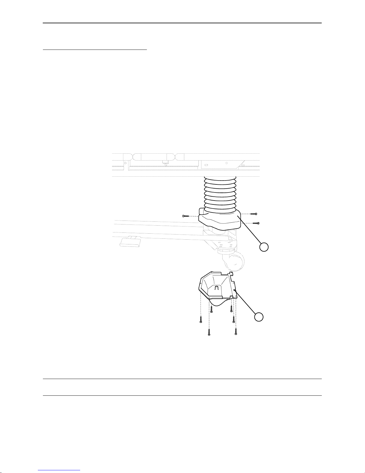
Chapter Four – Maintenance Procedures – Base
4.1 BASE COVER REMOVAL
UPPER LIFT COVER REMOVAL (UPPER LIFT COVER KIT P/N 3000–200–739)
Required Tools:
#2 Phillips Screwdriver Bungee Cord (or equivalent)
Removal Procedure: (This procedure will take approximately 5 minutes)
1. Unplug the power cord from the wall socket. Using a Phillips screwdriver, remove the 3 screws holding
the upper lift cover (A) to the base (as shown in the illustration).
2. Lift up the cover. If desired, hold the cover out of the way by using bungee cords or the equivalent to secure
it to the litter top.
3. Reverse the above steps to reattach the cover.
A
FOOT END
LOWER LIFT COVER REMOVAL
(LOWER LIFT COVER KIT P/N 3000–200–747)
Required Tools:
5/16” Socket Wrench
Removal Procedure: (This procedure will take approximately 5 minutes)
1. Unplug the power cord from the wall socket. Using a 5/16” socket, remove the 6 screws holding the lower
lift cover (B) to the base (as shown in the illustration).
2. Lower the cover away from the base and set it aside.
WARNING
The lift motor is not grounded and may present electrical hazard. Use caution when working around motors.
3. Reverse the above steps to reattach the cover. Be sure the manual override shaft is aligned with the hole
in the lower lift cover.
B
NOTE
The procedure for removing the lift covers is the same for both ends of the bed.
67
Page 68

Chapter Four – Maintenance Procedures – Base
4.1 BASE COVER REMOVAL (CONTINUED)
LOWERING BELLOWS
Required Tools:
5/16” Nut Driver #2 Phillips Screwdriver
B
A
HEAD END
Procedure: (This procedure will take approximately 5 minutes)
1. Unplug the power cord from the wall socket. Remove litter access panel #3 (A) (see page 94).
2. Using a 5/16” nut driver, remove the 2 screws (B) holding the bellows to the litter top (as shown in the illustration).
3. Allow the bellows to drop down.
NOTE
The power and sensor coil cords are secured to the bellows bracket. Pull the cords and guide them through
the plastic grommets at the lift header crossbar to allow adequate cord length for proper lowering of the bellows.
4. Reverse the above steps to reattach the bellows and litter access panel.
NOTE
The procedure for lowering the bellows is the same for both ends of the bed except, when lowering the foot
end bellows, litter access panel #1 must be removed (see page 93) instead of panel #3.
68
Page 69
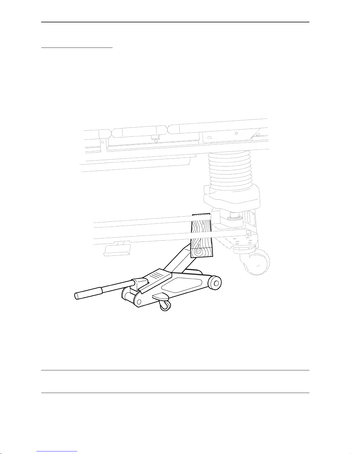
Chapter Four – Maintenance Procedures – Base
4.2 BRAKE SYSTEM
BRAKE RING (PAN) ASSEMBLY REMOVAL
Required Tools:
Hydraulic Floor Jack 3/4” Socket Wrench 3/8” Socket Wrench
#2 Phillips Screwdriver Bungee Cord (or equivalent) 5/16” Socket Wrench
Standard Screwdriver 9/16” Socket Wrench Needle–Nose Vise Grip Pliers
(2) 10mm Open End Wrenches 7/16” Socket Wrench (w/ext.) Wooden Brace
Removal Procedure: (This procedure will take approximately 35 minutes)
1. Unplug the power cord from the wall socket. Remove lower lift cover (see page 67).
2. Remove upper lift cover (see page 67).
3. Be sure the bed’s brakes are on. With a floor jack, lift the bed using a wooden brace (2x4 or equivalent)
on the inside of the base at the base tubes (as shown in the illustration above).
WARNING
The bed could be unstable when it is raised off the floor. Use care while working on the bed or personal injury
could result.
4. Using a Phillips screwdriver, remove the caster covers.
5. Using a 3/4” socket, remove the axle nut from both casters at the raised end of the bed.
69
Page 70

Chapter Four – Maintenance Procedures – Base
4.2 BRAKE SYSTEM (CONTINUED)
BRAKE RING (PAN) ASSEMBLY REMOVAL (CONTINUED)
B
C
C
A
6. Remove the casters from the caster horns by pulling the axle bolt out of the caster horn.
7. Using a 7/16” socket, remove the three screws (A) holding the brake pan on the bottom side of the base.
8. Using a 7/16” socket with an extension, remove the two remaining screws (B) holding the brake pan on
the base.
9. Using a screwdriver, pry off the retaining lock rings (C) holding the brake pivot arms to the brake link.
10. Lower the brake pan and ring assembly off the base, being careful not to damage the steer cable (if the
head end pan is being removed).
1 1. Note: This step is necessary only if the brake ring assembly at the head end of the bed is being removed.
Using a 9/16” socket wrench, remove the steer pedal. Using two 10 mm open end wrenches, remove the
two jam nuts holding the steer cable to the cable retainer. Using a 1/4” nut driver and needle–nose vise grips,
loosen and remove the cable retainer. Remove the two cables at the brake sensor switch. (Note the two
terminals being used so the cables will be reattached properly.)
12. Reverse the above steps to reattach the brake pan and ring assembly. If the head end pan was removed,
adjustment of the steer cable will be necessary (see page 75).
NOTE
For proper re–assembly of the brake ring and pan assembly, reattach all fasteners before securing the pivot
arms in place.
To properly secure the pivot arms, grasp both arms together and move them to the right. This will put the
cam into the proper position. Carefully install the pivot arm on the right first, then install the left pivot arm.
FOOT END
70
Page 71

Chapter Four – Maintenance Procedures – Base
4.2 BRAKE SYSTEM (CONTINUED)
BRAKE PEDAL REPLACEMENT (BRAKE PEDAL KIT P/N 3000–200–737)
Required Tools:
1/4” Hex Allen Wrench Torque Wrench Loctite 242
Procedure: (This procedure will take approximately 10 minutes)
1. Unplug the power cord from the wall socket.
2. Using a 1/4” hex allen wrench, remove the two bolts holding the brake pedal to the base and remove the
pedal.
3. Attach the new pedal using the bolts removed in step1.
NOTE
Use Loctite 242 when reinstalling the bolts and torque the bolts to 25 to 30 foot–pounds.
BRAKE CAM ASSEMBLY REPLACEMENT (BRAKE CAM KIT P/N 3000–200–733)
Required Tools:
Hydraulic Floor Jack 3/4” Socket Wrench 3/8” Socket Wrench
Phillips Screwdriver Bungee Cord (or equivalent) 1/4” Nut Driver
Standard Screwdriver 9/16” Socket Wrench Needle–Nose Pliers
5/16” Open End Wrench Needle–Nose Vise Grip Pliers 7/16” Socket Wrench (w/ swivel
elbow and extension)
Procedure: (This procedure will take approximately 60 minutes)
NOTE
Refer to drawing number 3000–200–350, Foot End Brake Assembly (pages 139 & 140) for part identification.
1. Unplug the power cord from the wall socket.
2. Remove the brake ring (pan) assembly (see page 69 & 70).
3. Using needle–nose pliers, remove the return springs (Y) attached to the brake pan assembly (A).
4. Using a 5/16” open end wrench, remove the two screws and nuts (P and Q) holding each plastic brake guide
bushing (N) to the ends of the pan assembly and remove the guides.
NOTE
The flange nuts (Q) do not need to be held with a wrench to loosen the mating screws.
5. Lift the brake ring and bar assembly out of the brake pan assembly.
NOTE
The replacement brake cam will be provided in a kit that will include the brake pan assembly with the attached
cam and tension spring.
6. Reverse the above steps to reassemble the brake ring (pan) assembly and to reattach it to the bed.
71
Page 72

Chapter Four – Maintenance Procedures – Base
4.2 BRAKE SYSTEM (CONTINUED)
BRAKE SENSOR REPLACEMENT (BRAKE SENSOR SWITCH KIT P/N 3000–200–735)
Required Tools:
5/16” Socket Wrench Side Cutters 5/16” Open End Wrench
C
D
B
A
HEAD END
Procedure: (This procedure will take approximately 25 minutes)
1. Unplug the power cord from the wall socket. Remove lower lift cover (see page 67).
2. Remove the two cables (A) from the switch. (Note the terminals where the cables were connected so the
cables will be reattached properly.)
3. Squeeze the switch retaining clips (B) and push up on the switch to remove it from the retaining bracket.
4. If the retaining bracket is bent or damaged, remove the two screws (C) and the cable tie (D) holding the
bracket to the frame and remove the bracket.
4. Reverse the above steps to install the new bracket and/or switch. Refer to page 63 for switch adjustment,
if necessary.
72
Page 73

Chapter Four – Maintenance Procedures – Base
4.3 STEER WHEEL CABLE REPLACEMENT AND ADJUSTMENT
(STEER CABLE KIT P/N 3000–200–701)
Required Tools:
5/16” Socket Wrench 5/16” Nut Driver
Needle–Nose Vise Grip Pliers Standard Screwdriver
(2) 10mm Open End Wrenches
C
A
FOOT END HEAD END
Replacement Procedure: (This procedure will take approximately 45 minutes)
1. Unplug the power cord from the wall socket. Remove lower lift cover (see page 67).
2. Remove spring (A).
3. Remove the steer cable (B) from the steer latch lever (C) at the foot end of the bed.
4. Using two 10mm open end wrenches, remove the two jam nuts securing the cable to the cable support
bracket at the head end of the bed on the patient’s right side.
5. Using a 5/16” nut driver, remove the cable clamp (D) holding the cable to the base at the head end of the
bed.
B
D
73
Page 74

Chapter Four – Maintenance Procedures – Base
4.3 STEER WHEEL CABLE REPLACEMENT AND ADJUSTMENT (CON-
TINUED)
D
5. Using a 1/4” nut driver and needle–nose vise grip pliers, loosen the bolt head in the cable retainer (D) and
slide the retainer off the cable. Pull the cable out of the bed.
NOTE
If the cable sheathing is not damaged, pull the cable from the head end of the bed and remove it from the
sheathing, leaving the sheathing on the bed. Push the new cable through the sheathing from the head end.
6. Reverse the above steps to attach the new cable.
74
Page 75

Chapter Four – Maintenance Procedures – Base
4.3 STEER WHEEL CABLE REPLACEMENT AND ADJUSTMENT (CON-
TINUED)
E
3/16”
Adjustment Procedure: (This procedure will take approximately 20 minutes)
If the steer wheel engages when the steer pedal is in the neutral or off position, slide the cable retainer (item
(D), page 74) toward the cable support bracket and tighten the retainer back down on the cable.
If the steer wheel does not hold properly when the pedal is in the steer position, slide the retainer away from
the cable support bracket and tighten the retainer back down on the cable.
NOTE
The ideal off position for the steer latch lever (E) to the steer wheel is approximately 3/16” between the end
of the lever and the caster horn.
75
Page 76

Chapter Four – Maintenance Procedures – Base
4.4 CASTER REPLACEMENT
Required Tools:
Floor Jack 1/2” Socket w/extension #2 Phillips Screwdriver
Bungee Cord (or equivalent) Wooden Brace
A
FOOT END – BOTTOM VIEW
Replacement Procedure: (This procedure will take approximately 10 minutes)
1. Unplug the power cord from the wall socket. Remove upper lift cover (see page 67).
2. Be sure the bed’s brakes are on. Using a floor jack and wooden brace, lift the end of the bed with the defective caster off the floor a few inches. IMPORTANT: See page 69 for proper bed lifting procedure.
3. Using a 1/2” socket with extension under the base, remove the four castle nuts (A) holding the caster as-
sembly to the base.
4. Reverse the above procedure to install the replacement caster.
NOTE
The upper lift cover was raised to allow access to the four carriage bolts which need to be held when the four
castle nuts are reinstalled.
76
Page 77

Chapter Four – Maintenance Procedures – Base
4.5 LIFT MOTOR AND CAPACITOR REMOVAL AND REPLACEMENT
(LIFT MOTOR KIT P/N 3000–200–727, LIFT CAPACITOR KIT P/N 3000–200–745)
Required Tools:
3/16” Hex Allen Socket 5/16” Socket Wrench Phillips Screwdriver
7/16” Open End Wrench Side Cutters Bungee Cord (or equivalent)
C
D
Procedure: (This procedure will take approximately 1 hour)
1. Unplug the power cord from the wall socket. Remove lower lift cover (see page 67).
2. Remove upper lift cover (see page 67).
3. Using a 5/16” nut driver, remove the two screws holding the front and back metal access panels to the lift
housing assembly and remove the panels (reference drawing on page 88).
4. Disconnect the two connectors (A) at the motor capacitor.
5. Disconnect the white connector (B) from the power cord.
6. Using side cutters, cut the cable ties holding the capacitor (C) to the base and remove the capacitor.
7. Using a 3/16” hex allen socket, remove the four screws (D) holding the motor assembly in the lift housing
and remove the motor assembly.
8. Use the access holes in the lift housing to view the alignment of the new motor drive shaft to the motor
coupler. Lift the motor into place and secure it with the bolts removed in step 7. Hold the nuts that the
bolts are being turned into through the access holes until the threads of the bolts are started.
9. Using cable ties, reinstall the new capacitor to the base.
NOTE
The drive shaft on the new motor probably will have to be turned to be aligned with the coupler. Use a 7/16”
open end wrench to turn the drive shaft of the motor.
10. Reattach the three connectors, return all wiring to its original position and reinstall all panels and covers.
NOTE
The procedure for lift motor and capacitor removal and replacement is the same for both ends of the bed.
B
A
FOOT END
77
Page 78

Notes
78
Page 79

Chapter Four – Maintenance Procedures – Base
4.6 LIFT UNIT
LIFT MOTOR ISOLATION PLATE REPLACEMENT
(LIFT MOTOR ISOLATION PLATE KIT P/N 3000–200–723)
Required Tools:
#2 Phillips Screwdriver 1/4” Nut Driver 3/8” Open End Wrench
3/8” Socket Wrench 3/16” Punch Hammer
Needle–Nose Pliers 5/16” Nut Driver 7/16” Open End Wrench
3/16” Hex Allen Socket (w/approx. 6” ext.)
E
E
D
C
A
F
C
B
A
Procedure: (This procedure will take approximately 45 minutes)
1. Unplug the power cord from the wall socket.
2. Remove the upper lift cover (see page 67).
3. Remove lower lift cover (see page 67).
4. Remove the front and rear metal access covers (reference the illustration on page 88).
5. Using a 3/16” hex Allen socket with 6” extension, remove the four bolts holding the lift motor to the base
and carefully lower the motor to the floor.
79
Page 80

Chapter Four – Maintenance Procedures – Base
4.6 LIFT UNIT (CONTINUED
LIFT MOTOR ISOLATION PLATE REPLACEMENT (CONTINUED)
6. Remove the motor coupler (D) and bushings (E) through the access holes.
7. Using a 3/16” punch and hammer, remove the top roll pin on the manual drive hex shaft coupling and set
the shaft and coupler assembly aside.
8. Using a 3/8” open end wrench, remove the four stand–offs (F) from the lift housing and lower the isolation
plate (B) with the attached stand–offs.
9. Using a 3/8” socket, remove the two nuts and washers (A) and the two stand–offs from one end of the
isolation plate and set the nuts, washers and stand–offs aside.
10. Rotate the end of the isolation plate with the stand–offs removed toward the access opening and tilt it up
and out of the opening.
11. Remove the two remaining stand–offs from the isolation plate. Attach the two stand–offs to one end of the
new isolation plate.
12. Reverse the above steps to reattach all components to the bed.
CAUTION
When re–installing the stand–offs to the lift housing, do not use a wrench to start the threads of the stand–offs
and take care to install them straight or damage to the stand–offs could occur.
NOTE
When reinstalling the lift motor, use the access holes in the lift housing to view the alignment of the motor
drive shaft to the motor coupler. The drive shaft on the motor probably will have to be turned to be aligned
with the coupler. Use a 7/16” open end wrench to turn the drive shaft of the motor.
The four rubber bushings (C) will be included in the replacement kit with the new isolation plate. The motor
coupler (D) and bushings (E) will be removed with the isolation plate and can be re–used with the new plate,
unless damaged. If only the motor coupler and bushings need to be replaced, see page 87.
80
Page 81

Chapter Four – Maintenance Procedures – Base
4.6 LIFT UNIT (CONTINUED)
LIFT HOUSING REMOVAL AND REPLACEMENT
Required Tools:
Standard Screwdriver Phillips Screwdriver Bungee Cord (or equivalent)
5/16” Socket Wrench 9/16” Socket Wrench Needle–Nose Vise Grip Pliers
3/8” Open End Wrench Small Standard Screwdriver 5/16” Open End Wrench
Side Cutters 5/16” Nut Driver 7/32” Hex Allen Socket Wrench
3/16” Hex Allen Socket (w/ approx. 6” extension) Sawhorses (or equivalent)
Procedure: (This procedure will take approximately 1 hour)
1. Unplug the power cord from the wall socket. Remove lower lift cover (see page 67).
2. Remove upper lift cover (see page 67).
3. Remove litter access panel at end of bed needing service (see pages 93 & 94).
4. Remove lift motor and capacitor (see page 77).
5. Remove lift potentiometer (see page 89).
6. Using a 5/16” open end wrench, remove the cable clamps holding the power and sensor coil cords on top
of the lift housing assembly (reference screws (A) on page 92). Cut the cable ties and disconnect the coil
cords from underneath the lift housing. The power and sensor coil cords should now be free from the lift
housing assembly. Drape them up out of the way.
7. Using a 7/32” hex allen socket, remove the two screws (A) holding the lift screws to the header crossbar
plate.
CAUTION
The bed litter retracts on rollers. Secure it to prevent it from rolling while the procedure is being done.
A
HEAD END
81
Page 82

Chapter Four – Maintenance Procedures – Base
4.6 LIFT UNIT (CONTINUED)
LIFT HOUSING REMOVAL AND REPLACEMENT (CONTINUED)
B
FOOT END – BOTTOM VIEW
8. Lift the litter top up and support it about 6” above the lift screws with sawhorses or the equivalent.
9. Under the base, using a 9/16” socket, remove the four nuts (B) holding the lift housing to the base.
10. Lift up and out on the lift housing assembly to remove it from the base. (See pages 83–86 for servicing
procedures for lift housing components.)
CAUTION
After service has been completed on the lift housing, the inner and outer screws must be ”timed”. If this timing
measurement is not equally maintained between the two lift drive screws, the drive screws will not move up
equally, and damage to the bed’s moving parts could result. (Refer to step 10 on page 84 for proper timing
procedure.)
CAUTION
See pages 91 and 92 for proper reattachment procedure for power and sensor coil cords.
11. Reverse the above steps to reinstall the lift housing assembly after service is completed.
NOTE
The procedure for lift housing removal and replacement is the same for both ends of the bed.
82
Page 83

Chapter Four – Maintenance Procedures – Base
4.6 LIFT UNIT (CONTINUED)
LIFT GEAR REPLACEMENT (IDLER GEAR KIT P/N 3000–200–707, MANUAL IDLER GEAR KIT
P/N 3000–200–709. MOTOR PINION GEAR KIT P/N 3000–200–711)
OUTER AND INNER LIFT DRIVE SCREW REPLACEMENT (OUTER SCREW KIT P/N
3000–200–713, INNER SCREW KIT P/N 3000–200–715)
LIFT DRIVE LOWER AND UPPER NUT REPLACEMENT
(COMPLETE LIFT ASSEMBLY KIT P/N 3000–200–705, SINGLE TUBE OF GREASE P/N
3000–200–700)
This complete procedure will take approximately 90 minutes.
Required Tools:
5/16” Socket Wrench ”Syntech” Synthetic Grease 3/16” Punch
Phillips Screwdriver 9/16” Socket Wrench 5/16” Nut Driver
Bungee Cord (or equivalent) Standard Screwdriver Large Snap Ring Pliers
1/4” Hex Allen Wrench Small Standard Screwdriver Hammer
Side Cutters 1/4” Open End Wrench 3/8” Socket
3/8” Open End Wrench 7/32” Hex Allen Socket Wrench
Needle–Nose Vise Grip Pliers 3/16” Hex Allen Socket Wrench (w/approx. 6” ext.)
CAUTION
After service has been completed on the lift housing, the inner and outer screws must be ”timed”. If this timing
measurement is not equally maintained between the two lift drive screws, the drive screws will not move up
equally, and damage to the bed’s moving parts could result. Refer to step 10 for proper timing procedure.
1. Unplug the power cord from the wall socket. Remove lower lift cover (see page 67).
2. Remove lift motor and capacitor (see page 77).
3. Remove lift housing (see page 81 & 82).
4. Using a 1/4” hex allen wrench, remove the four screws (K) and lock washers holding the housing cap (A)
to the lift housing ( lock washers not shown).
5. Lift up on the housing cap to remove it and set it aside. Note the position of the washers before they are
disturbed. Some washers may stick to the housing cap as it is removed.
6. If the guide bushings (B) need to be replaced, push them out of the housing cap from the top.
LIFT GEAR REPLACEMENT
CAUTION
Take note of the proper washer arrangement for re–assembly (see illustration #2) or damage to the unit could
occur.
7. To replace gears (C), lift straight up on the defective gear(s) to remove. Idler gear (D) can be removed
by lifting it straight up and off the lift housing. To remove motor pinion gear (E) and manual idler gear (F),
first use a 3/8” socket to remove the four fiber nuts holding the isolation plate to the lift housing. Pull straight
down on the motor coupler to remove it. To remove motor pinion gear (E), remove the snap ring from
underneath and pull the gear and shaft assembly out of the lift housing. To remove manual idler gear (F),
use a 3/16” punch and hammer to remove the roll pin securing the gear shaft to the manual hex shaft coupler and pull the gear and shaft assembly out of the lift housing.
NOTE
New gears will be provided in a kit containing the gear with the attached shaft, appropriate spring washers,
thrust bearings, timing plate and grease. Be sure to apply grease generously to all gears whenever new
gears are installed.
83
Page 84

Chapter Four – Maintenance Procedures – Base
4.6 LIFT UNIT (CONTINUED)
LIFT DRIVE INNER SCREW AND UPPER NUT REPLACEMENT
NOTE
The inner screw can be removed with or without the lift housing cap attached.
8. For Inner Lift Drive Screw (L) replacement, using large snap ring pliers, remove snap ring (G) holding the
inner screw to the lift housing. Push up on the inner screw from the bottom of the outer screw (M) to remove.
CAUTION
When reinstalling the snap ring (G), be sure to position it as shown in illustration 1 or damage to the unit could
occur.
To replace the upper nut (H) after removing the inner screw, turn the upper nut off the inner screw. Install
the new upper nut in the same manner. The replacement inner screw will come with the attached upper nut.
LIFT DRIVE OUTER SCREW AND LOWER NUT REPLACEMENT
9. To remove the outer screw (M), while the inner screw is still removed, push the outer screw out from underneath the lift housing.
To replace the lower nut (J) after removing the outer screw, turn the lower nut off the outer screw. Install
the new lower nut in the same manner. The replacement outer screw will come with the attached lower
nut.
CAUTION
Apply grease generously to the outer and the inner screws when they are installed or damage to the unit could
occur.
TIMING OF INNER AND OUTER SCREWS
10. For proper ”timing” of the inner and outer screws (items L and M), reattach the lift housing cap (A) with both
output gears (C) removed and manually turn both inner and outer screws until they are flush with the top
edge of the caps (as shown in the illustration on page 86). Assure there is no gap between the cap and
the lift housing.
11. Reattach all gears and washers and reinstall the housing cap.
NOTE
Do not allow the wave washers on gears (E) and (F) to overlap with the flat washers. Align the ”ears” on the
large thrust washers with the ”pockets” in the housing cap.
12. Being sure the inner screws have not lost the timing position, attach the timing plate across the top of the
drive screws using the bolts removed from the header crossbar in step 3.
13. Reattach the lift housing assembly to the base of the bed and run the drive screws up electrically to the
top, with the timing plate still attached.
14. Remove the timing plate and reattach the drive screws to the litter top.
15. Reinstall all removed covers and panels.
16. Test the bed for proper operation before returning it to service.
84
Page 85

Chapter Four – Maintenance Procedures – Base
4.6 LIFT UNIT (CONTINUED)
LIFT GEAR REPLACEMENT ILLUSTRATION
OUTER AND INNER LIFT DRIVE SCREW REPLACEMENT ILLUSTRATION
LIFT DRIVE LOWER AND UPPER NUT REPLACEMENT ILLUSTRATION
G
H
L
B
ILLUSTRATION #1
M
A
K
C
C
F
J
D
E
ILLUSTRATION #2
85
Page 86

Chapter Four – Maintenance Procedures – Base
4.6 LIFT UNIT (CONTINUED)
TIMING OF INNER AND OUTER LIFT SCREWS ILLUSTRATION
INNER
SCREW
86
OUTER
SCREW
LIFT
HOUSING
COVER
Page 87
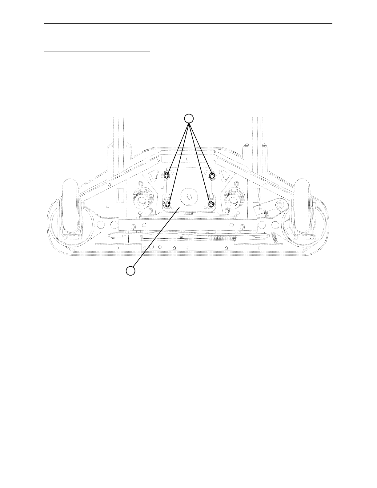
Chapter Four – Maintenance Procedures – Base
4.6 LIFT UNIT (CONTINUED)
LIFT MOTOR COUPLER REPLACEMENT (LIFT MOTOR COUPLER KIT P/N 3000–200–705)
Required Tools:
Phillips Screwdriver Bungee Cord (or equivalent) 5/16” Socket Wrench
5/16” Nut Driver 1/2” Socket w/extension
A
B
FOOT END – BOTTOM VIEW
Procedure: (This procedure will take approximately 30 minutes)
1. Unplug the power cord from the wall socket. Remove upper lift cover (see page 67).
2. Remove lower lift cover (see page 67).
3. Using a 3/8” socket with extension, remove the four nuts and washers (A) holding the isolation plate (B)
to the lift housing and lower the lift motor and isolation plate assembly to allow access to the coupler. Take
care not to drop the isolation plate onto the base.
87
Page 88

Chapter Four – Maintenance Procedures – Base
4.6 LIFT UNIT (CONTINUED)
LIFT MOTOR COUPLER REPLACEMENT (CONTINUED)
D
C
F
E
4. Using a 5/16” nut driver, remove the two screws (C) holding the metal access panel (D) to the lift housing.
5. The motor coupler (E) can now be removed from the lift housing through the access hole.
NOTE
The replacement motor coupler will come with new rubber bushings.
6. Reverse the above steps to install the new motor coupler and bushings.
NOTE
Removal of access cover (F) is shown only for reference in the procedure for lift motor and capacitor removal
and replacement on page 77.
88
Page 89

Chapter Four – Maintenance Procedures – Base
4.6 LIFT UNIT (CONTINUED)
LIFT POTENTIOMETER REPLACEMENT AND ADJUSTMENT
(LIFT POT KIT (HEAD) P/N 3000–200–729, LIFT POT KIT (FOOT) P/N 3000–200–731)
Required Tools:
Small Standard Screwdriver Phillips Screwdriver Bungee Cord (or equivalent)
5/16” Socket Wrench 3/8” Open End Wrench Side Cutters
C
B
A
Procedure: (This procedure will take approximately 45 minutes)
1. Unplug bed from wall socket. Remove lower lift cover (see page 67).
2. Remove upper lift cover (see page 67) and support with bungee cord.
3. Remove litter access panels #1 and #2 (see page 93).
4. Using side cutters, cut the cable tie (A) holding the pot cable to the coil cord.
5. Unplug the pot cable from the sensor coil cord. If replacing a pot at the head end of the bed, unplug the
cables attached to the brake sensor switch.
6. Pull the pot cable up through the base.
7. Using a 3/8” open end wrench, remove the two screws (B) holding the pot housing (C) to the lift housing.
89
Page 90

Chapter Four – Maintenance Procedures – Base
4.6 LIFT UNIT (CONTINUED)
LIFT POTENTIOMETER REPLACEMENT AND ADJUSTMENT (CONTINUED)
8. Lift up and out on the pot housing assembly to remove it from the lift housing.
NOTE
The replacement pot will come attached to the pot housing along with the plastic gear.
9. Properly ground yourself (see page 10 for static discharge precautions).
10. Be sure the bed power cord is unplugged from the wall socket. Remove the jumper stored at P6 on the
litter CPU board (see page 199 for location of CPU board). Install the jumper at P2 (on the litter CPU) in
the last set of pins toward the head end of the bed.
11. Plug in the power cord and carefully move the jumper from P2 back to P6. Run the bed fully up electrically.
12. Before installing the new pot on the bed, turn it clockwise until it stops. Turn it back counterclockwise two
full (360) revolutions. This allows a ”window” position for proper upper and lower limits.
13. Reverse steps 4–8 to install the new pot and pot housing assembly. Be sure to plug the new pot in and
do not unplug the bed power cord. Leave the litter access panels off.
NOTE
Be sure to maintain the pot position while installing.
14. Run the bed down electrically until it stops.
15. Press and hold the Bed Motion Lock key on the foot board until the Bed Motion Lock indicator begins to
flash. If the LED does not flash, press and hold the key again . The limits are now programmed.
16. Unplug the power cord to remove the bed from diagnostics.
17. Plug the power cord into a properly grounded wall receptacle and test the operation of the bed. The distance
between the floor and the top of the litter seat section (without a mattress) should be 15 1/2” – 16” with the
litter fully down, and 29 1/4” – 29 3/4” with the litter fully up.
NOTE
If the siderail bed up/down lockout light is flashing when the power cord is plugged in, one of the lift pots is
either out of adjustment or unplugged (or both). Check and reset limits.
18. Reinstall all access panels and covers.
90
Page 91

Chapter Four – Maintenance Procedures – Base
4.6 LIFT UNIT (CONTINUED)
POWER AND SENSOR COIL CORD REPLACEMENT
(POWER COIL CORD KIT P/N 3000–200–743, SENSOR COIL CORD KIT P/N 3000–200–741)
Required Tools:
Standard Screwdriver Side Cutters
Bungee Cord (or equivalent) 5/16” Nut Driver
Phillips Screwdriver 5/16” Socket Wrench
Procedure: (This procedure will take approximately 45 minutes)
1. Unplug the bed power cord from the wall socket. Remove lower lift cover (see page 67).
2. Remove upper lift cover (see page 67).
3. Remove litter access panels at the end of the bed needing service (see page 93 & 94).
4. Using side cutters, cut the cable ties holding the power and sensor coil cords to the base. Remove the
ground wire coming from the sensor cord that is attached to the base (note the star washer arrangement).
5. Disconnect the cables going to the motor and the lift potentiometer (at the head end, the sensor cord is
also attached to the brake switch sensor).
6. Pull both cords up through the frame of the bed and the lift housing.
7. Using a 5/16” nut driver, remove the two screws (A) holding the cable clamps* to the top of the lift housing.
8. Using a 5/16” nut driver, remove the two screws (B) securing the cable clamps* to the underside of the
header crossbar assembly.
9. Pull both coil cords up through the header crossbar assembly.
10. Remove the two grommets protecting the cords on top of the header crossbar assembly.
11. Using side cutters, cut the cable ties holding both cords to the 1” cross frame.
12. Remove the grommet both cords are routed through at the 1” cross frame.
13. Using a 5/16” nut driver, remove the screw supporting the corner metal plate that holds the motion interrupt
switch at each corner. (This provides access to the coil cord connectors.)
14. Disconnect the power and sensor coil cords from the connectors.
15. The cords should now be completely removed from the bed. Reverse the above steps to install the new
power and sensor cords*.
CAUTION
*When the power and sensor coil cords are being replaced, secure the cable clamps to the cords at the first
coil on the top and on the bottom to assure there is not too much slack in the cords between the top of the
lift housing assembly and the bottom of the header crossbar. Be sure the clamps are fastened at exactly the
correct angle, as shown by the arrows in the illustration. Arrange the cords exactly as shown in the illustration
(left in front of right). If this is not done correctly, damage to the cords will result.
91
Page 92
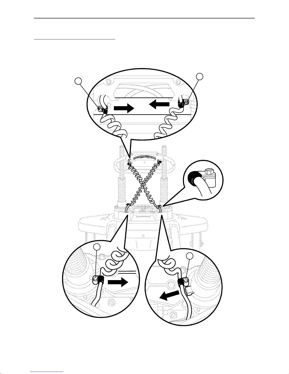
Chapter Four – Maintenance Procedures – Base
4.6 LIFT UNIT (CONTINUED)
POWER AND SENSOR COIL CORD REPLACEMENT ILLUSTRATION
B
B
A
A
VIEW FROM CENTER OF BED
92
Page 93

Chapter Five – Maintenance Procedures – Litter
5.1 REMOVAL OF LITTER ACCESS PANELS
(FOOT END LITTER COVER #1 KIT P/N 3000–300–729, LITTER ELECTRICAL COVER #2 KIT P/N
3000–300–721, HEAD END LITTER COVER #3 KIT P/N 3000–300–727, FOWLER MOTOR COVER #4
KIT P/N 3000–300–725, LITTER MID COVER #5 KIT P/N 3000–300–723)
Required Tools:
Standard Screwdriver #2 Phillips Screwdriver
1/4” Nut Driver
NOTE
Before removing the panels, put all siderails down and in the tucked position, run the head section up electrically to approximately 30 and run the knee section fully up. Pull up on the handle on the corner of the foot
section and pivot the foot and knee sections out of the way to allow proper access for removing panels.
1
2
GROUND SCREW
FOOT END
Removal Procedure: (This procedure will take approximately 10 minutes)
1. Unplug the power cord from the wall socket.
2. Lift up on panel #1 to remove it from the foot end of the bed.
NOTE
Panel #1 is secured with dual lock and no tools are necessary for its removal.
3. Using a standard screwdriver, remove the 9 plastic 1/4 turn screws holding panel #2 to the litter at the foot
end of the bed.
4. Using a Phillips screwdriver, remove the ground screw.
5. Lift panel #2 up and out to remove.
93
Page 94

Chapter Five – Maintenance Procedures – Litter
5.1 REMOVAL OF LITTER ACCESS PANELS (CONTINUED)
6. For easier access, be sure the Fowler has been moved up to approximately 30. Using a Phillips screwdriver, remove the two screws holding panel #3 to the litter. Lift panel #3 up and out to remove it from underneath panel #5 and off the litter.
NOTE
Midsection panel #5 does not need to be removed for routine servicing of the bed.
7. Using a 1/4” nut driver, remove the 4 screws securing panel #4.
8. Lift up on panel #4 and lay it toward the head end of the bed.
9. Reverse the above steps to reattach the panels.
CAUTION
Be sure ground screw is reinstalled in location shown in the illustration below.
3
GROUND SCREW
5
4
HEAD END
94
Page 95

Chapter Five – Maintenance Procedures – Litter
5.2 REMOVAL OF MOTION INTERRUPT PANEL
Required Tools:
5/16” Nut Driver
B
FOOT END
Removal Procedure: (This procedure will take approximately 10 minutes)
1. Unplug the power cord from the wall receptacle.
2. Using a 5/16” nut driver, remove the 2 screws (A) holding the interrupt panel (B) to the litter at the foot end
of the bed (as shown in the illustration).
3. There is a ground strap between the motion interrupt panel and the litter frame. Using a 5/16” nut driver,
remove the screw and star washer securing the ground strap to the litter frame. Save the screw and star
washer for reuse.
4. Lift up and forward on the head end of the panel to disengage the hangers from the litter top.
5. Carefully lower the panel and allow it to rest on the base tubes.
6. Reverse the above steps to reattach the panel.
A
95
Page 96

Chapter Five – Maintenance Procedures – Litter
5.3 MOTION INTERRUPT SWITCH REPLACEMENT
Required Tools:
5/16” Nut Driver 1/4” Nut Driver
Standard Screwdriver
Procedure: (This procedure will take approximately 30 minutes)
1. Unplug the power cord from the wall receptacle.
2. Remove the motion interrupt panel (see page 95).
3. Remove appropriate litter access panel(s) (see pages 93 & 94).
4. Disconnect the two wires at the switch being replaced.
NOTE
Notice the terminals being used on the switch so the wires will be attached properly to the new switch.
5. Squeeze the retention clips on the switch and push down on the switch to remove it from the support
bracket.
6. Reverse the above steps to install the new switch.
7. Activate the motion stop system to assure it is functioning properly: press and hold down the BED DOWN
key. As the bed lowers, lift up on each corner of the motion interrupt pan individually and assure the downward motion stops each time. Release the pan and allow the downward motion to continue.
96
Page 97

Chapter Five – Maintenance Procedures – Litter
5.4 KNEE SECTION
LIMIT SETTING – KNEE MOTOR
Required Tools:
5/16” Nut Driver
A
FOOT END
Procedure: (This procedure will take approximately 30 minutes)
WARNING
The knee motor is not grounded and may present electrical hazard. Use caution when working around motors.
1. Remove the motion interrupt panel (see page 95).
2. Lower the knee section until it is flat (0).
3. Lightly tap the Gatch down button until the bolt and bushing (C) are centered in the slot.
4. Unplug the power cord from the wall socket.
5. Using a 5/16” nut driver, loosen screws (A).
6. Slide the cam guide (B) toward the head end of the bed just until the microswitch is activated (a clicking
noise should be heard).
NOTE
Check that the cam ”bump” is on the ”foot” side of the switch actuator.
7. Tighten the screws (A).
8. Plug the power cord into a properly grounded wall receptacle.
B
C
9. Ensure the knee section will raise to 40 and lower to flat (0) before returning the bed to service. If the
upper limit is above 40, readjust the cam guide (B) toward the head end of the bed until 40 is achieved.
If the upper limit is below 40, readjust the cam guide toward the foot end of the bed until 40 is achieved.
97
Page 98

Chapter Five – Maintenance Procedures – Litter
5.4 KNEE SECTION (CONTINUED)
CAM AND CAM GUIDE REPLACEMENT – HEAD AND KNEE MOTOR (FOWLER/GATCH C A M
AND CAM GUIDE KIT P/N 3000–300–709)
Required Tools:
5/16” Nut Driver 7/16” Nut Driver
Standard Screwdriver 7/16” Open End Wrench
KNEE MOTOR
C
A
HEAD MOTOR
D
B
D
Procedure: (This procedure will take approximately 30 minutes)
1. Unplug the power cord from the wall socket. Remove the motion interrupt panel (see page 95).
2. Remove litter access panels 1 and 2 (see page 93).
3. If the head motor cam and cam guide are being replaced, use a 5/16” nut driver to remove the screw (A)
holding the cam retention wire to the ball nut assembly.
If the knee motor cam and cam guide are being replaced, use a 7/16” socket and a 7/16” open end wrench
to remove the nut (B) holding the cam retention wire to the bed. (Do not remove the bolt).
4. Disconnect the cables (C) from the micro switches.
5. Using a 5/16” nut driver, remove the two screws (D) holding the cam and cam guide to the support bracket
and remove the cam and cam guide with the attached micro switches from the bed.
6. Reverse the above steps to install the replacement cam and cam guide/micro switch assembly.
7. If the head motor cam and cam guide were replaced, refer to page 102 for ”Limit Setting – Head Motor”.
If the knee motor cam and cam guide were replaced, refer to page 97 for ”Limit Setting – Knee Motor”.
C
98
Page 99

Chapter Five – Maintenance Procedures – Litter
5.4 KNEE SECTION (CONTINUED)
DRIVE SCREW AND NUT REPLACEMENT – KNEE MOTOR
(GATCH DRIVE SCREW KIT P/N 3000–300–715)
Required Tools:
5/16” Nut Driver 1/4” Nut Driver Standard Screwdriver
Hex Allen Wrench Side Cutters 7/16” Open End Wrench
7/16” Socket Wrench 3/16” Punch Hammer
A
C
B
Procedure: (This procedure will take approximately 45 minutes)
1. Remove the knee motor (see page 101). (The motor carriage can be removed with the motor still attached.
The motor cable must be disconnected from the litter if this is done – see steps 6 and 7, page 101).
2. Unhook hinge pin from the knee section.
3. Using a 5/16” nut driver from the top, remove the two screws (A) holding the motor carriage assembly to
the litter and the screw (B) holding the ground strap to the litter.
4. Using a 5/16” nut driver underneath the litter, remove the eight screws (B) holding the motor carriage assembly to the litter assembly.
5. Lower the motor carriage assembly from underneath the litter.
99
Page 100

Chapter Five – Maintenance Procedures – Litter
5.4 KNEE SECTION (CONTINUED)
DRIVE SCREW AND NUT REPLACEMENT – KNEE MOTOR (CONTINUED)
F
B
A
C
TOP VIEW
G HJ
E
D
6. Place the carriage assembly on a work bench in the position shown in the illustration above. Remove the
motor if it hasn’t already been done (see page 101).
7. Using a 3/16” punch and a hammer, remove the roll pin (A) at the left end of the carriage assembly.
8. Remove the washer (B) and bushing at the left end of the carriage assembly.
9. Turn the drive screw (C) counterclockwise to access the roll pin (H) holding the coupler (D) on the drive
screw.
10. Support the drive screw on the carriage housing. Do not let the plastic portion of the coupler rest on the
carriage housing.
11. Using a 3/16” punch and hammer, remove the roll pin (H) holding the coupler on the drive screw.
12. Pull the coupler off the drive screw and remove the bearing, washer and bushing.
13. Turn the drive screw clockwise and out of the right end of the carriage.
14. Remove the washer (J) from the right end of the drive screw.
15. Slide the drive screw back to the right and through the end of the carriage.
16. Turn the drive screw to remove it from the drive screw nut (E).
17. Using a 7/16” socket and 7/16” open end wrench, remove the nut, bolt and washer (F) holding the drive
screw nut and the cam wire link to the main link (G).
18. Reverse the above steps to install the new drive screw and nut and to reattach all components to the bed.
Check bushings removed in steps 7 and 11 for wear and replace, if necessary.
NOTE
Generously apply grease to the drive screw nut when installing the new nut.
Before reinstalling the carriage assembly on the litter, manually turn the drive nut approximately half–way
down the length of the drive screw. This will allow easier realignment to the litter.
CAUTION
Assure the knee motor stops properly at both upper and lower electric limits. If it does not, refer to page 97
for ”Limit Setting – Knee Motor”.
100
 Loading...