

Page 1
IMPORTANT
File in your
maintenance
records
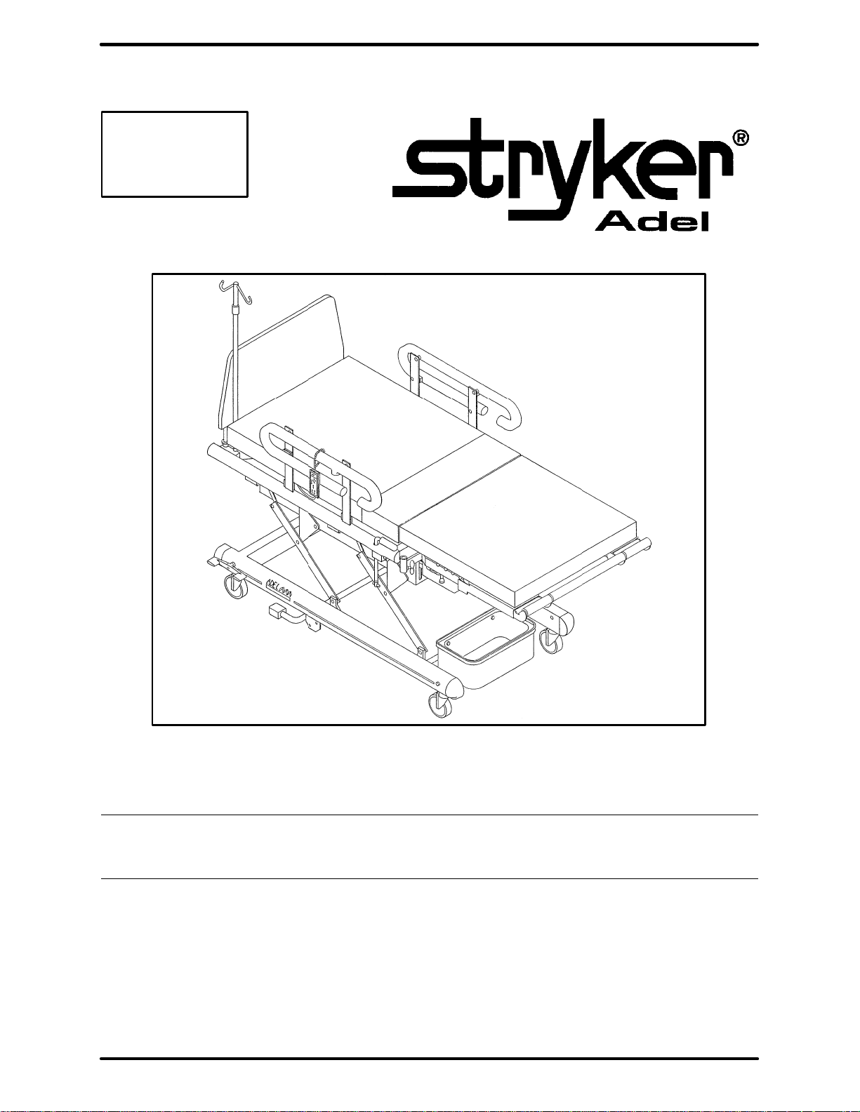
2100 Childbearing Bed
MAINTENANCE MANUAL
For Parts or Technical Assistance
1–800–327–0770
Page 2

Table of Contents
INTRODUCTION 2. . . . . . . . . . . . . . . . . . . . . . . . . . . . . . . . . . . . . . . . . . . . . . . . . . . . . . . . . . . . . . . . . . . . . . . . . . . . . . . . . . . . .
SPECIFICATIONS 2. . . . . . . . . . . . . . . . . . . . . . . . . . . . . . . . . . . . . . . . . . . . . . . . . . . . . . . . . . . . . . . . . . . . . . . . . . . . . . . . . . . .
WARNING / CAUTION / NOTE DEFINITION 2. . . . . . . . . . . . . . . . . . . . . . . . . . . . . . . . . . . . . . . . . . . . . . . . . . . . . . . . . . . . . .
UNPACKING INSTRUCTIONS 3. . . . . . . . . . . . . . . . . . . . . . . . . . . . . . . . . . . . . . . . . . . . . . . . . . . . . . . . . . . . . . . . . . . . . . . . .
SET–UP PROCEDURES 3. . . . . . . . . . . . . . . . . . . . . . . . . . . . . . . . . . . . . . . . . . . . . . . . . . . . . . . . . . . . . . . . . . . . . . . . . . . . . .
PREVENTATIVE MAINTENANCE 4. . . . . . . . . . . . . . . . . . . . . . . . . . . . . . . . . . . . . . . . . . . . . . . . . . . . . . . . . . . . . . . . . . . . . . .
TROUBLESHOOTING GUIDE 5,6. . . . . . . . . . . . . . . . . . . . . . . . . . . . . . . . . . . . . . . . . . . . . . . . . . . . . . . . . . . . . . . . . . . . . . . .
SCHEMATIC DIAGRAMS 7,8. . . . . . . . . . . . . . . . . . . . . . . . . . . . . . . . . . . . . . . . . . . . . . . . . . . . . . . . . . . . . . . . . . . . . . . . . . . .
HEAD MOTOR REPLACEMENT 9. . . . . . . . . . . . . . . . . . . . . . . . . . . . . . . . . . . . . . . . . . . . . . . . . . . . . . . . . . . . . . . . . . . . . . .
BED MOTOR REPLACEMENT 10. . . . . . . . . . . . . . . . . . . . . . . . . . . . . . . . . . . . . . . . . . . . . . . . . . . . . . . . . . . . . . . . . . . . . . . .
FOOT MOTOR REPLACEMENT 11. . . . . . . . . . . . . . . . . . . . . . . . . . . . . . . . . . . . . . . . . . . . . . . . . . . . . . . . . . . . . . . . . . . . . .
CONTROLLER (CIRCUIT BOARD) REPLACEMENT 12. . . . . . . . . . . . . . . . . . . . . . . . . . . . . . . . . . . . . . . . . . . . . . . . . . . . .
HAND PENDANT REPLACEMENT 13. . . . . . . . . . . . . . . . . . . . . . . . . . . . . . . . . . . . . . . . . . . . . . . . . . . . . . . . . . . . . . . . . . . .
MEMBRANE SWITCH REPLACEMENT 13. . . . . . . . . . . . . . . . . . . . . . . . . . . . . . . . . . . . . . . . . . . . . . . . . . . . . . . . . . . . . . . .
COMPRESSOR REPLACEMENT 14. . . . . . . . . . . . . . . . . . . . . . . . . . . . . . . . . . . . . . . . . . . . . . . . . . . . . . . . . . . . . . . . . . . . . .
HEAD PANEL–MATTRESS REPLACEMENT 15. . . . . . . . . . . . . . . . . . . . . . . . . . . . . . . . . . . . . . . . . . . . . . . . . . . . . . . . . . . .
SEAT PANEL–MATTRESS REPLACEMENT 16. . . . . . . . . . . . . . . . . . . . . . . . . . . . . . . . . . . . . . . . . . . . . . . . . . . . . . . . . . . .
MANIFOLD REPLACEMENT 17. . . . . . . . . . . . . . . . . . . . . . . . . . . . . . . . . . . . . . . . . . . . . . . . . . . . . . . . . . . . . . . . . . . . . . . . . .
LIMIT SWITCH REPLACEMENT 18. . . . . . . . . . . . . . . . . . . . . . . . . . . . . . . . . . . . . . . . . . . . . . . . . . . . . . . . . . . . . . . . . . . . . .
COIL REPLACEMENT 19. . . . . . . . . . . . . . . . . . . . . . . . . . . . . . . . . . . . . . . . . . . . . . . . . . . . . . . . . . . . . . . . . . . . . . . . . . . . . . .
COUNTERBALANCE SPRING REPLACEMENT 20. . . . . . . . . . . . . . . . . . . . . . . . . . . . . . . . . . . . . . . . . . . . . . . . . . . . . . . . .
TILT/TRENDELENBERG SPRING REPLACEMENT AND ADJUSTMENT 21. . . . . . . . . . . . . . . . . . . . . . . . . . . . . . . . . . .
FIELD REPLACEMENT PARTS 22. . . . . . . . . . . . . . . . . . . . . . . . . . . . . . . . . . . . . . . . . . . . . . . . . . . . . . . . . . . . . . . . . . . . . . .
GENERAL CLEANING 23. . . . . . . . . . . . . . . . . . . . . . . . . . . . . . . . . . . . . . . . . . . . . . . . . . . . . . . . . . . . . . . . . . . . . . . . . . . . . . .
ASSEMBLY DRAWINGS AND PARTS LISTS
Bed Assembly 24. . . . . . . . . . . . . . . . . . . . . . . . . . . . . . . . . . . . . . . . . . . . . . . . . . . . . . . . . . . . . . . . . . . . . . . . . . . . . . . . . . . . .
Base Assembly 25–27. . . . . . . . . . . . . . . . . . . . . . . . . . . . . . . . . . . . . . . . . . . . . . . . . . . . . . . . . . . . . . . . . . . . . . . . . . . . . . . . .
Tilt Arm Assembly 28. . . . . . . . . . . . . . . . . . . . . . . . . . . . . . . . . . . . . . . . . . . . . . . . . . . . . . . . . . . . . . . . . . . . . . . . . . . . . . . . . .
Tilt Lever Assembly 28. . . . . . . . . . . . . . . . . . . . . . . . . . . . . . . . . . . . . . . . . . . . . . . . . . . . . . . . . . . . . . . . . . . . . . . . . . . . . . . . .
Litter Assembly 29–32. . . . . . . . . . . . . . . . . . . . . . . . . . . . . . . . . . . . . . . . . . . . . . . . . . . . . . . . . . . . . . . . . . . . . . . . . . . . . . . . . .
Handgrip Assembly 33. . . . . . . . . . . . . . . . . . . . . . . . . . . . . . . . . . . . . . . . . . . . . . . . . . . . . . . . . . . . . . . . . . . . . . . . . . . . . . . . .
Foot Pan Mount Assembly 34. . . . . . . . . . . . . . . . . . . . . . . . . . . . . . . . . . . . . . . . . . . . . . . . . . . . . . . . . . . . . . . . . . . . . . . . . . .
Foot Lift Assembly 35. . . . . . . . . . . . . . . . . . . . . . . . . . . . . . . . . . . . . . . . . . . . . . . . . . . . . . . . . . . . . . . . . . . . . . . . . . . . . . . . . .
Lift Bar Assembly 36. . . . . . . . . . . . . . . . . . . . . . . . . . . . . . . . . . . . . . . . . . . . . . . . . . . . . . . . . . . . . . . . . . . . . . . . . . . . . . . . . . .
Drive Crank Assembly 37. . . . . . . . . . . . . . . . . . . . . . . . . . . . . . . . . . . . . . . . . . . . . . . . . . . . . . . . . . . . . . . . . . . . . . . . . . . . . . .
Limit Switch Assembly 38. . . . . . . . . . . . . . . . . . . . . . . . . . . . . . . . . . . . . . . . . . . . . . . . . . . . . . . . . . . . . . . . . . . . . . . . . . . . . .
Head Motor Assembly 39. . . . . . . . . . . . . . . . . . . . . . . . . . . . . . . . . . . . . . . . . . . . . . . . . . . . . . . . . . . . . . . . . . . . . . . . . . . . . . .
Foot Motor Assembly 40. . . . . . . . . . . . . . . . . . . . . . . . . . . . . . . . . . . . . . . . . . . . . . . . . . . . . . . . . . . . . . . . . . . . . . . . . . . . . . .
Lift Motor Assembly 41. . . . . . . . . . . . . . . . . . . . . . . . . . . . . . . . . . . . . . . . . . . . . . . . . . . . . . . . . . . . . . . . . . . . . . . . . . . . . . . . .
Headboard Assembly 42. . . . . . . . . . . . . . . . . . . . . . . . . . . . . . . . . . . . . . . . . . . . . . . . . . . . . . . . . . . . . . . . . . . . . . . . . . . . . . .
Siderail Assembly 43. . . . . . . . . . . . . . . . . . . . . . . . . . . . . . . . . . . . . . . . . . . . . . . . . . . . . . . . . . . . . . . . . . . . . . . . . . . . . . . . . .
Rear Siderail Arm Assembly 44. . . . . . . . . . . . . . . . . . . . . . . . . . . . . . . . . . . . . . . . . . . . . . . . . . . . . . . . . . . . . . . . . . . . . . . . .
Front Siderail Arm Assembly 45. . . . . . . . . . . . . . . . . . . . . . . . . . . . . . . . . . . . . . . . . . . . . . . . . . . . . . . . . . . . . . . . . . . . . . . . .
Wood Siderail Assembly 46. . . . . . . . . . . . . . . . . . . . . . . . . . . . . . . . . . . . . . . . . . . . . . . . . . . . . . . . . . . . . . . . . . . . . . . . . . . . .
Nurse Comm. Siderail Assembly 47. . . . . . . . . . . . . . . . . . . . . . . . . . . . . . . . . . . . . . . . . . . . . . . . . . . . . . . . . . . . . . . . . . . . . .
Siderail Mounting Bar Assembly 48. . . . . . . . . . . . . . . . . . . . . . . . . . . . . . . . . . . . . . . . . . . . . . . . . . . . . . . . . . . . . . . . . . . . . .
Splitter Box Assembly 49. . . . . . . . . . . . . . . . . . . . . . . . . . . . . . . . . . . . . . . . . . . . . . . . . . . . . . . . . . . . . . . . . . . . . . . . . . . . . . .
Foot Pan Assembly 50. . . . . . . . . . . . . . . . . . . . . . . . . . . . . . . . . . . . . . . . . . . . . . . . . . . . . . . . . . . . . . . . . . . . . . . . . . . . . . . . .
Foot Pan Latch Assembly 51. . . . . . . . . . . . . . . . . . . . . . . . . . . . . . . . . . . . . . . . . . . . . . . . . . . . . . . . . . . . . . . . . . . . . . . . . . . .
Foot End Mattress And Push Bar Assembly 52. . . . . . . . . . . . . . . . . . . . . . . . . . . . . . . . . . . . . . . . . . . . . . . . . . . . . . . . . . . .
Push Bar Assembly 53. . . . . . . . . . . . . . . . . . . . . . . . . . . . . . . . . . . . . . . . . . . . . . . . . . . . . . . . . . . . . . . . . . . . . . . . . . . . . . . . .
Head Section Assembly 54. . . . . . . . . . . . . . . . . . . . . . . . . . . . . . . . . . . . . . . . . . . . . . . . . . . . . . . . . . . . . . . . . . . . . . . . . . . . .
Seat Mattress Assembly 55. . . . . . . . . . . . . . . . . . . . . . . . . . . . . . . . . . . . . . . . . . . . . . . . . . . . . . . . . . . . . . . . . . . . . . . . . . . . .
Hand Crank Assembly 56. . . . . . . . . . . . . . . . . . . . . . . . . . . . . . . . . . . . . . . . . . . . . . . . . . . . . . . . . . . . . . . . . . . . . . . . . . . . . .
Foot Rest Assembly 57. . . . . . . . . . . . . . . . . . . . . . . . . . . . . . . . . . . . . . . . . . . . . . . . . . . . . . . . . . . . . . . . . . . . . . . . . . . . . . . .
LIMITED WARRANTY
Obtaining Parts and Service 58. . . . . . . . . . . . . . . . . . . . . . . . . . . . . . . . . . . . . . . . . . . . . . . . . . . . . . . . . . . . . . . . . . . . . . . . . .
Supplemental Warranty Coverage 58. . . . . . . . . . . . . . . . . . . . . . . . . . . . . . . . . . . . . . . . . . . . . . . . . . . . . . . . . . . . . . . . . . . .
Return Authorization 59. . . . . . . . . . . . . . . . . . . . . . . . . . . . . . . . . . . . . . . . . . . . . . . . . . . . . . . . . . . . . . . . . . . . . . . . . . . . . . . .
Freight Damage Claims 59. . . . . . . . . . . . . . . . . . . . . . . . . . . . . . . . . . . . . . . . . . . . . . . . . . . . . . . . . . . . . . . . . . . . . . . . . . . . .
Page 3

Introduction
INTRODUCTION
This manual is designed to assist you with the maintenance of the 2100 Childbearing Bed. Read it thoroughly
before using the equipment or beginning any maintenance on it.
SPECIFICATIONS
Maximum Weight Capacity 300 pounds (135 kilograms)
Electrical 3 motor function: Head–Bed–Foot
6 function patient comfort
120 VAC, 60 Hz, 4 Amp – 105 to 135 VAC operating range.
Current leakage less than 100 microamperes.
Hospital grade plug and 3–wire heavy duty cord.
Compatible with non–flammable anesthetic agents and oxygen by nasal catheter or mask.
WARNING
The 2100 is equipped with a hospital grade plug for protection against shock hazard. It must be plugged directly into a properly grounded three–prong receptacle. Grounding reliability can be achieved only when a
hospital grade receptacle is used.
WARNING / CAUTION / NOTE DEFINITION
The words WARNING, CAUTION and NOTE carry special meanings and should be carefully reviewed.
WARNING
The personal safety of the patient or user may be involved. Disregarding this information could result in injury
to the patient or user.
CAUTION
These instructions point out special procedures or precautions that must be followed to avoid damaging the
equipment.
NOTE
This provides special information to make maintenance easier or important instructions clearer.
To assure its proper use and the safety of patients and staff, the 2100 has been marked with the following
caution and warning labels:
DANGER Explosion Hazard – do not use in the presence of flammable anesthetics.
CAUTION This unit is equipped with a hospital grade attachment plug. Grounding reliability can be
achieved only when equipment is connected to equivalent receptacle.
CAUTION Electrical shock hazard. Do not remove cover panels. Refer all servicing to qualified personnel.
CAUTION Disconnect power cord before hand cranking. Remove hand crank before connecting power
cord.
2
Page 4

Unpacking and Initial Set–Up Procedures
UNPACKING INSTRUCTIONS
Refer to unpacking instructions located on outside of marked crate.
SET–UP PROCEDURES
It is important that the Stryker Adel 2100 Childbearing Bed is working properly before it is put into service.
The following list will help assure that each part of the bed is tested.
S Plug the bed into a properly grounded, hospital grade wall receptacle.
WARNING
The 2100 is equipped with a hospital grade plug for protection against shock hazard. It must be plugged directly into a properly grounded three–prong receptacle. Grounding reliability can be achieved only when a
hospital grade receptacle is used.
S Assure the siderails raise and lower smoothly and lock in the up position.
S Assure that the brakes hold when the brake pedal is engaged (see page 4 for adjustment).
S Run through each function on the hand pendant to assure that each function is working properly.
Beds equipped with siderail control option only:
S Plug the interface cable into the 37 pin connector in the litter frame at the head end of the bed, and
into the ”Patient Station”, ”Head Wall”, ”Docker Station”, or equivalent (whichever applies).
S Run through each function on the siderail control panels to assure that each function is working prop-
erly.
3
Page 5

Preventative Maintenance
PREVENTATIVE MAINTENANCE PROGRAM
Observation of the following scheduled maintenance and inspection program will help assure continuous
trouble–free operation of your 2100 Childbearing Bed.
ACTIVITY MONTHLY INTERVAL TOOLS REQUIRED SUPPLIES REQUIRED
Lubricate screw threads on
leg support clamping
knobs.
Clean and lubricate vertical
slide rods that support the
foot panels.
Inspect and adjust wheel
brake shoes on central
locking casters.*
Lubricate pin joints on lift
mechanism.
Inspect power cord and
plug for damage due to
abrasion or cutting.
Inspect exposed metal surfaces and apply touch–up
paint where required.
Check electrical safety by
testing for leakage current
and ground continuity.
Scratched wood components. Remove loose dust;
spray a light coat of Varathane over the area. Apply
a second coat in approximately six hours.
Remove stains from mattress covers.
Each occurrence See page 23.
6
6
24
6
12
12
12
N/A
N/A
N/A
Phillips screwdriver
N/A Lubricant
N/A
N/A
Electrical testing equipment
N/A
Lubricant
Lubricant
N/A
N/A
Touch–up paint**
N/A
Satin Varathane #91
*T o adjust brakes, remove 6 mm screw from caster. Rotate housing to the right (counterclockwise) to reduce
braking force or to the left (clockwise) to increase braking force. Reinstall the 6 mm screw.
NOTE
Left front caster is not a brake caster
**Touch–up paint
Tan Brown (spray) p/n 0064–06–00
Tan Brown (touch–up) p/n 0064–08–00
Camel (spray) p/n 0064–07–00
Camel (touch–up) p/n 0064–09–00
4
Page 6
Service Information
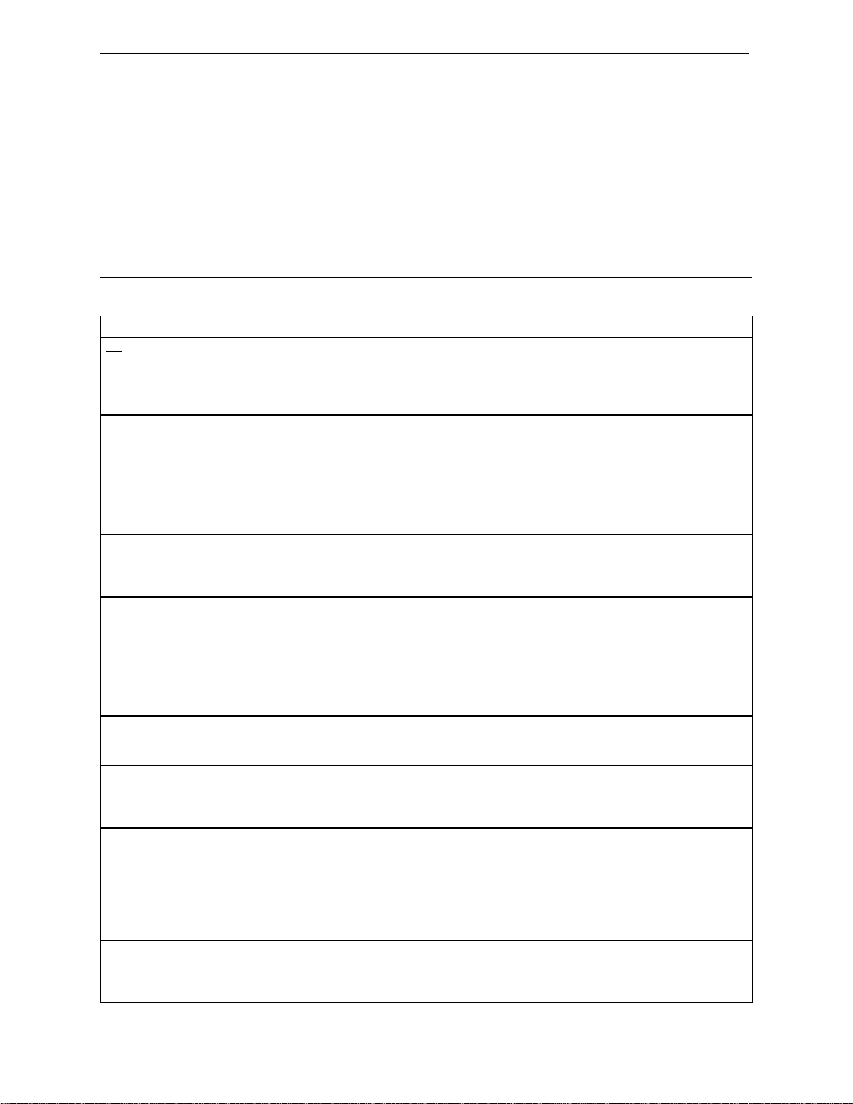
TROUBLESHOOTING GUIDE
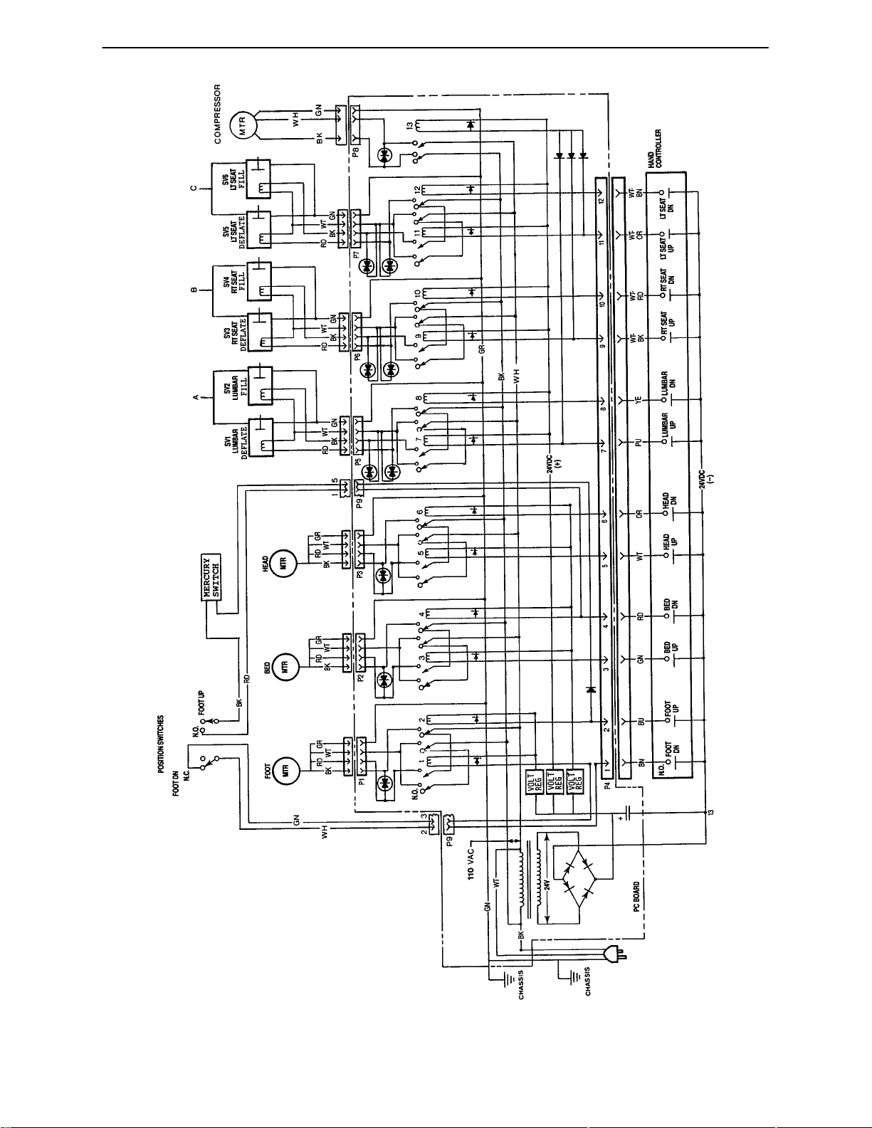
The following chart is intended to assist qualified service personnel with identifying and correcting problems
associated with the electrical/pneumatic systems. The schematic diagrams on the following pages should
be used for reference. A volt–ohm meter will be required.
WARNING
Because these problem solving methods may involve interchanging motor plugs or pneumatic air lines to isolate the fault or probable cause, the patient should always be removed from the bed before corrective action
is taken.
PROBLEM/SYMPTOM POSSIBLE CAUSE RECOMMENDED ACTION
No motors functioning. No power supply.
Defective power cord or plug.
Defective electrical controller.
One motor not functioning – head,
bed, or foot.
Incorrect travel limits – head, bed or
foot.
One pneumatic solenoid not functioning – lumbar, seat left or seat
right.
No inflation of lumbar, seat left, or
seat right.
No inflation or deflation of lumbar,
seat left, or seat right.
No air to operate lumbar, seat left, or
seat right.
Slow filling or emptying of air from
lumbar, seat left, or seat right.
Squeal or noise in lift mechanism Or,
bed motor labors when bed is fully
loaded with 300 pounds.
Loose wire at motor plug or receptacle.
Defective motor.
Defective pendant controller.
Defective membrane switch.
Defective electrical controller (circuit
board).
Physical blockage of movement.
Defective motor or drive screw.
Motor drive tube out of adjustment.
Loose wire at solenoid plug.
Defective solenoid.
Defective pendant controller.
Defective membrane switch.
Defective electrical controller (circuit
board).
Leaking bladder. Replace head panel–mattress or
Kinked lines.
Defective solenoid.
Defective compressor.
Loose wire at motor connectors.
Kinked lines.
Contamination in valves.
Dry joints.
Defective counterbalance spring.
Test voltage at wall receptacle
Examine and test for continuity.
Test input and output voltages (see
schematic page 7). Listen for relay
actuation.
Inspect connectors; check continuity.
Interchange motor plugs to isolate.
Interchange motor plugs to isolate.
Check continuity.
Test input and output voltages (see
schematic page 7). Listen for relay
actuation.
Visually inspect moving parts.
Replace motor (see pages 9–11).
Reset (see motor replacement–
pages 9–11)
Inspect connectors; check continuity.
Interchange solenoid plugs to isolate. Replace coil.
Interchange solenoid plugs to isolate.
Check continuity.
Test input and output voltages (see
schematic page 7).
seat panel–mattress (see page 15 or
16).
Inspect lines for kinking: re–route, if
necessary.
Interchange solenoid plugs to isolate.
Replace compressor (see page 14).
Inspect connectors: check continuity;
test voltage.
Inspect lines for kinking: re–route, if
necessary.
Isolate by switching lines. Replace
manifold (see page 17).
See prev. maintenance (page 4).
Check for obstruction, bent rod, or
bent housing. Remove obstruction.
Replace spring (see page 20).
5
Page 7
Service Information
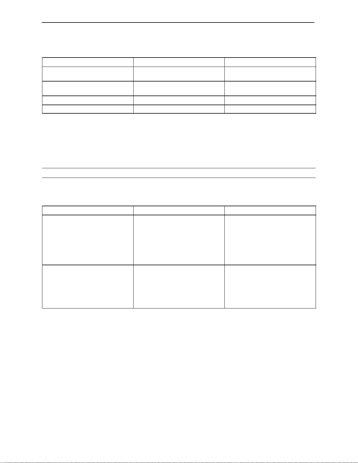
TROUBLESHOOTING GUIDE (CONTINUED)
PROBLEM/SYMPTOM POSSIBLE CAUSE RECOMMENDED ACTION
Bed does not tilt when lever is depressed.
Bed tilts when weight is applied to
opposite ends.
Brakes do not lock wheels. Tire wear. Readjust casters
Brakes hard to apply. Brakes over–adjusted. Readjust casters
NURSE COMMUNICATION SIDERAIL OPTION TROUBLESHOOTING GUIDE
Before attempting to diagnose an apparent problem, be sure the power cord is plugged into a properly
grounded hospital grade wall receptacle and the bed has power. Be sure the nurse call cable has a good
connection at both the wall and the bed. If both these things are done, proceed with diagnosis.
CAUTION
Membrane switches are fragile. Never depress a membrane dome unless the switch is lying on a flat, firm
surface. Doing otherwise will cause the switch to fail eventually. When applying a new membrane switch,
lay it down evenly; do not roll it down. Once a membrane switch has been peeled back, it cannot be reused.
Tilt spring out of adjustment.
Defective tilt spring.
Tilt spring out of adjustment.
Defective tilt spring.
Readjust spring length.
Replace spring (see page 21).
Readjust spring length.
Replace spring (see page 21).
PROBLEM/SYMPTOM POSSIBLE CAUSE RECOMMENDED ACTION
Some or all of the pillow speaker
functions aren’t working properly.
A control button on one side of the
siderail doesn’t work or the T.V.
sounds different on one side.*
Defective cable (from bed to wall). Switch the cable with one that is
known to work. If this solves the
problem, replace the cable. If not, try
a bed from another room that is
known to be O.K. If the problem persists on the bed that is known be
O.K., the problem is in the wiring in
the wall.
Defective control switch.
Defective siderail P.C. board.
Defective splitter box.***
Defective siderail cable.
Replace switch.**
Replace siderail PC board.**
Switch the siderail cables at the splitter box. If the problem switches
sides, replace splitter box. If the
problem stays in the same siderail,
replace cable.
* For audio problems, check resistance across pins 4 and 35 on the 37 pin connector at the rear of the bed.
The reading should be 22.5 "5 ohms for 45 ohm systems or 4 "2 ohms for 8 ohm systems. A reading
double these values indicates no connection to the speaker in one of the siderails. If the sound is inadequate, turn the volume up to its highest level by holding the button for 30 seconds. Adjust the remote speaker output volume on the TV to its highest level. Turn the TV back down until the volume at the remote speakers just begins to be affected to reduce distortion caused by overdriving the speakers. Cover the speaker
grills separately and compare the sound loss to be sure the sound is balanced between the two speakers.
** For problems inside the siderails, peel back the outside membrane switch to expose the seven screws hold-
ing the plastic housing to the siderail assembly. Remove the screws and carefully disconnect the membrane switch from the siderail PC board.
*** For problems in the splitter box, remove the box and examine the LED’s next to the relays. If the LED comes
on when the function button is pressed, a faint click should be audible. If no click is heard, replace the relay .
If replacing the relay doesn’t solve the problem or if the LED doesn’t light, replace the splitter box PC board.
If the problem still persists, replace the splitter cable. (Refer to Splitter Box Assembly (page 49) for part
reference.)
6
Page 8
Schematic Diagram
7
Page 9
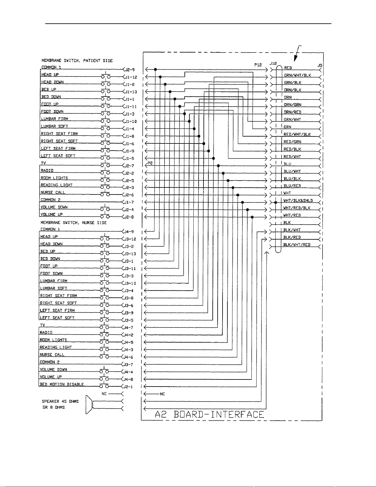
Nurse Communication Schematic Diagram
LEFT
SIDERAIL
CABLE
8
Page 10
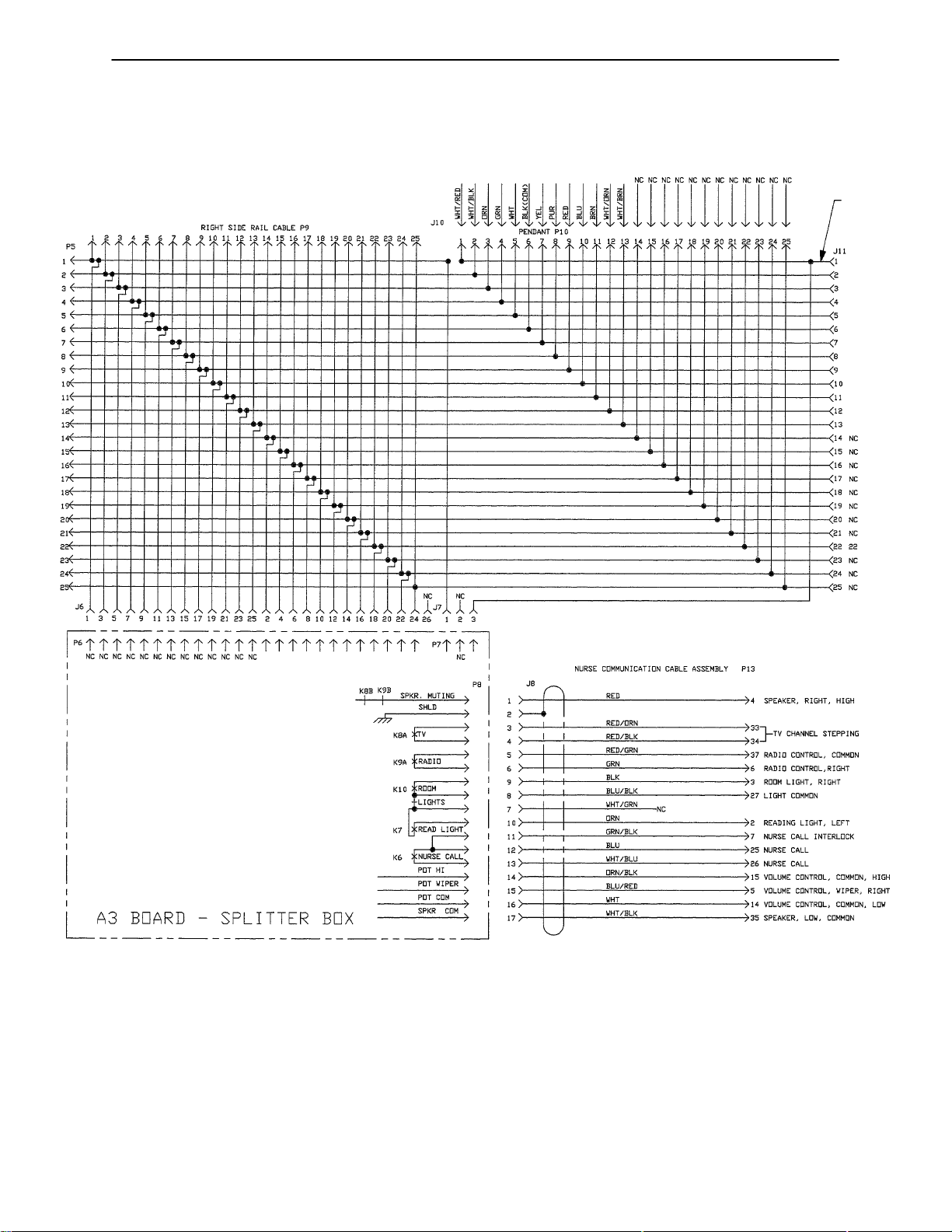
Nurse Communication Schematic Diagram
THIS WIRE
COLORED
STRIPE
TO BED
CIRCUIT
BOARD
8a
Page 11

Notes
Page 12

Service Information
HEAD MOTOR REPLACEMENT
HEAD MOTOR KIT #88–3979–18–00
Required Tools:
7/16” Hex Socket & Ratchet 1/4” Allen Wrench
Phillips Screwdriver Loctite 242
Replacement Procedure:
1. Raise bed to full up position.
CAUTION
DIsconnect power plug from wall receptacle.
2. Use hand crank to lower head panel.
3. Remove headboard, foot mattress, foot extension, foot pans, I.V. pole and leg supports.
4. Set brake with casters turned as though the bed is being pushed backwards. Assure the head end of the
bed is at least five feet away from the wall when it is upright.
5. With the assistance of another person, lift the foot end of the bed chassis and rotate the locked rear casters
until the upper frame–headboard mounts touch the floor.
6. Disconnect the head motor plug and unscrew the cord strain relief clamp.
7. Remove the four hex screws from the motor trunnion mounts.
8. Remove the two hex screws and washers from the drive tube/pull bar.
9. Motor, drive tube and mounting hardware can now be removed as a unit.
NOTE
The head motor is supplied to you with the drive tube retracted (ref. 1/8” from motor case). Do not allow drive
tube to rotate.
10. Remove the two white trunnion bearings from the defective motor and place them onto the new motor trunnion mounts. Place the motor assembly back into the litter frame and attach with the four hex screws.
Use Loctite 242 to secure the screws.
11. To hook up the head panel to the drive tube, plug the motor lead into the control box, replace the strain relief
clamp, and plug the power cord into the wall receptacle. Hold the drive tube to prevent rotation and press
the ”HEAD DOWN” button on the hand pendant until the drive tube aligns with the head panel pull bar
holes. Install the two hex screws and washers.
12. Be sure all screws, cables and electrical connections are secure.
13. With the assistance of another person, tilt the bed back down to the floor.
14. Operate the head motor from full down position to full up to full down again. Make sure the motor stops
electrically before the drive tube bottoms out on the mechanical stops. Check motor cable for proper routing and attachment to prevent interference.
15. Check electrical safety in conformance with specified hospital requirements (leakage current, ground continuity, etc.)
16. Remount all items removed in step three and return the bed to service.
9
Page 13

Service Information
BED MOTOR REPLACEMENT
BED MOTOR KIT #88–0316–08–00
Required Tools:
7/16” Hex Socket & Ratchet 1/4” Allen Wrench
Phillips Screwdriver 3/8” Nut Driver
Loctite 242 & 271
Replacement Procedure:
1. Lower head panel.
CAUTION
Disconnect power plug from wall receptacle.
The 2100 bed is equipped with gas springs to assist the lift mechanism. To prevent the seat section from
expanding away from the chassis when the bed motor is removed, use the hand crank to raise the bed to
full up before placing the bed in servicing position. If the motor is jammed or cannot be hand cranked, tie the
seat section to the chassis with straps or strong rope.
2. Remove headboard, foot mattress, foot extension, foot pans, I.V. pole and leg supports.
3. Set brake with casters turned as though the bed is being pushed backwards. The casters at the head end
of the bed must be five feet away from the wall.
4. With the assistance of another person, lift the foot end of the bed chassis and rotate the locked rear casters
until the upper frame–headboard mounts touch the floor.
5. Disconnect the bed motor plug and unscrew the cord strain relief clamp.
6. Remove the four hex screws from the motor trunnion mounts.
7. Remove the two Allen screws and sleeves from the drive tube/crank.
8. Motor, drive tube, and mounting hardware can now be removed as a unit.
9. Remove the two white trunnion bearings from the defective motor and place them onto the new motor trunnion mounts. Place the motor assembly back into the litter frame and attach with the four hex screws.
Use Loctite 242 to secure the screws.
NOTE
The bed motor is supplied with the drive tube retracted (ref. 1/8” from motor case). Do not allow drive tube
to rotate.
10. Using Loctite 271, install the two 1/4” Allen screws and sleeves.
11. Plug the motor lead into the control box and replace the strain relief clamp.
12. Be sure all screws, cables, and electrical connections are secure.
13. With the assistance of another person, tilt the bed back down to the floor.
14. Plug the power cord into the wall receptacle. Operate the bed motor from full up position to full down to
full up again. Be sure the motor stops electrically before the drive tube bottoms out on the mechanical
stops. Check motor cable for proper routing and attachment to prevent interference.
15. Check electrical safety in conformance with specified hospital requirements (leakage current, ground continuity, etc.)
16. Remount all items removed in step two and return bed to service.
10
Page 14

Service Information
FOOT MOTOR REPLACEMENT
FOOT MOTOR KIT #88–0316–09–00
Required Tools:
7/16” Hex Socket & Ratchet 1/4” Allen Wrench
Phillips Screwdriver Loctite 242 & 271
Replacement Procedure:
1. Raise bed to full up position.
CAUTION
DIsconnect power plug from wall receptacle.
2. Use hand crank to lower foot pans to full down position.
3. Remove headboard, foot mattress, foot extension, foot pans, I.V. pole and leg supports.
4. Set brake with casters turned as though the bed is being pushed backwards. The casters at the head end
of the bed must be five feet away from the wall.
5. With the assistance of another person, lift the foot end of the bed chassis and rotate the locked rear casters
until the upper frame–headboard mounts touch the floor.
6. Disconnect the foot motor plug and unscrew the cord strain relief clamp.
7. Remove the four hex screws from the motor trunnion mounts.
8. Remove the two Allen screws and sleeves from the drive tube/crank.
9. Motor, drive tube and mounting hardware can now be removed as a unit.
10. Remove the two white trunnion bearings from the defective motor and place them onto the new motor trunnion mounts. Place the motor assembly back into the litter frame and attach with the four hex screws.
Use Loctite 242 to secure the screws.
NOTE
The bed motor is supplied with the drive tube retracted (ref. 1/8” from motor case). Do not allow drive tube
to rotate.
11. Install the two 1/4” Allen screws and sleeves.
12. Plug the motor lead into the control box and replace the strain relief clamp.
13. Be sure all screws, cables, and electrical connections are secure.
14. Plug the power cord into the wall receptacle. Operate the foot motor from full down position to full up to
full down again. Be sure the motor stops electrically before the drive tube bottoms out on the mechanical
stops. Check for proper cable routing and attachment to prevent interference.
15. With the assistance of another person, tilt the bed back down to the floor.
16. Check electrical safety in conformance with specified hospital requirements (leakage current, ground continuity, etc.)
17. Remount all items removed in step three and return the bed to service.
11
Page 15

Service Information
CONTROLLER (CIRCUIT BOARD) REPLACEMENT
CONTROLLER KIT #88–0316–02–00 (for beds with serial numbers 880596 and below)
CONTROLLER KIT #88–0316–21–00 (for beds with serial numbers 880597 and above)
Required Tools:
3/8” Nut Driver #1 Phillips Screwdriver
5/16” Nut Driver Pliers
Replacement Procedure:
1. Raise bed to the full up position.
CAUTION
DIsconnect power plug from wall receptacle.
2. Remove headboard, foot mattress, foot extension, foot pans, I.V. pole and leg supports.
3. Set brake with casters turned as though the bed is being pushed backwards. The casters at the head end
of the bed must be five feet away from the wall.
4. With the assistance of another person, lift the foot end of the bed chassis and rotate the locked rear casters
until the upper frame–headboard mounts touch the floor.
5. Unplug all connectors on controller box.
6. Remove the two screws holding on the controller box cover, remove the cover, and disconnect the power
cord.
7. Remove the three mounting nuts and 2 stand–offs and loosen the cable clamps. Remove the defective
circuit board.
8. Attach replacement circuit board to control box base with the four star washers and screws. (On later model
beds without a control box base, attach the circuit board to the litter.)
9. Remount the box to the litter frame with four star washers and nuts.
10. Connect the power cord and attach the cover with the two screws.
11. Plug all connectors into the controller box and re–tighten the cable clamps.
12. Be sure all screws, cables, and electrical connections are secure.
13. With the assistance of another person, tilt the bed back down to the floor.
14. Plug the power cord into the wall receptacle. Run through all functions on the hand pendant at least three
times to ensure proper operation. Check for proper cable routing and attachment to prevent interference.
15. Check electrical safety in conformance with specified hospital requirements (leakage current, ground continuity, etc.)
16. Remount all items removed in step two and return bed to service.
12
Page 16

Service Information
HAND PENDANT REPLACEMENT
HAND PENDANT KIT #88–0316–03–00
Required Tools:
Phillips Screwdriver 3/8” Nut Driver
Replacement Procedure:
1. Raise bed to full up position.
2. Remove screw at head end of motor cover and remove cord strain relief clamps.
3. Unplug pendant cable from controller box and remove.
4. Route replacement pendant cable to control box and plug into controller.
5. Attach strain relief clamps and install screw at head end of motor cover.
6. Be sure all screws and connections are secure.
7. Run through all the functions on the hand pendant at least three times to ensure proper operation.
8. Return bed to service.
MEMBRANE SWITCH REPLACEMENT
MEMBRANE SWITCH KIT #88–0316–04–00
Required Tools:
5/64” Allen Wrench
Replacement Procedure:
CAUTION
Disconnect power plug from wall receptacle.
1. Remove the four screws from the back of the hand pendant.
2. Unplug the membrane switch assembly at the ribbon cable connector.
3. Plug the replacement membrane switch ribbon into the connector.
4. Place the membrane switch into the pendant housing, being sure to properly locate the strain relief bar.
Insert and tighten the four socket screws.
5. Run through all the functions of the membrane switch at least three times to ensure proper operation.
6. Return bed to service.
13
Page 17

Service Information
COMPRESSOR REPLACEMENT
COMPRESSOR KIT #88–0316–24–00
Required Tools:
11/32” Nut Driver Blade Screwdriver
Side (Wire) Cutter
Replacement Procedure:
1. Raise the bed to the full up position.
CAUTION
Disconnect power plug from wall receptacle.
2. Remove headboard, foot mattress, foot extension, foot pans, I.V. pole and leg supports.
3. Set brake with casters turned as though the bed is being pushed backwards. The casters at the head end
of the bed must be five feet away from the wall.
4. With the assistance of another person, lift the foot end of the bed and rotate the locked rear casters until
the upper frame–headboard mounts touch the floor.
5. Remove ground wire screw. Pull lead wire connectors apart and cut tubing line next to compressor fitting.
6. Remove the three mounting nuts and washers and the defective compressor.
7. Install the replacement compressor and shock mounts in the litter frame with the three star washers and
nuts.
8. Connect the ground wire with the star washer and screw. Push the electrical connectors together and push
the tubing end over the compressor outlet fitting.
9. Be sure all screws, cables and electrical connections are secure.
10. With the assistance of another person, tilt the bed back down to the floor.
1 1. Plug the power cord into the wall receptacle. Run through all functions on the hand pendant at least three
times to ensure proper operation. Check for proper cable routing and attachment to prevent interference.
12. Check electrical safety in conformance with specified hospital requirements (leakage current, ground continuity, etc.)
13. Remount all items removed in step two and return bed to service.
14
Page 18

Service Information
HEAD PANEL–MATTRESS REPLACEMENT
HEAD PANEL–MATTRESS KIT #88–0316–10–00
Required Tools:
7/32” Allen Wrench Phillips Screwdriver
Side (Wire) Cutter
Replacement Procedure:
1. Raise head panel to approximately 30_.
2. Raise bed to the full up position.
CAUTION
Disconnect power plug from wall receptacle.
3. Remove headboard, foot mattress, foot extension, foot pans, I.V. pole and leg supports.
4. Set brake with casters turned as though the bed is being pushed backwards. The casters at the head end
of the bed must be five feet away from the wall.
5. Unfasten Velcro strap and remove over–mattress cover.
6. Cut tie–wraps to free tubing (note routing of tubing to ensure it will be reinstalled properly).
7. Behind the head panel, separate the head mattress vinyl tubing at the middle of the two inch ”J” clip.
8. Remove the eight cap screws from the head panel support arms to release the head panel assembly with
mattress.
9. Feed lumbar tubing line through litter access hole and place head panel base ribs in support arm tracks.
Avoid kinking or pinching tubing.
10. Install the eight cap screws.
11. With barb supplied in kit, match and cut tubing and splice together.
12. Replace over–cover and pull it taut with the Velcro strap.
13. Plug the power cord into the wall receptacle. Run through all functions on the hand pendant at least three
times to ensure proper operation. Check for proper cable routing and attachment to prevent interference.
14. Remount all items removed in step three and return bed to service.
15
Page 19

Service Information
SEAT PANEL–MATTRESS REPLACEMENT
SEAT PANEL–MATTRESS KIT #88–0316–11–00
Required Tools:
3/8” Nut Driver Phillips Screwdriver
SIde (Wire) Cutter
Replacement Procedure:
1. Raise head panel to approximately 30_.
2. Raise bed to the full up position.
CAUTION
Disconnect power plug from wall receptacle.
3. Remove headboard, foot mattress, foot extension, foot pans, I.V. pole and leg supports.
4. Remove over–mattress cover, loosening Velcro straps and screws on underside of head panel.
5. Set brake with casters turned as though the bed is being pushed backwards. The casters at the head end
of the bed must be five feet away from the wall.
6. With the assistance of another person, lift the foot end of the bed chassis and rotate the locked rear casters
until the upper frame–headboard mounts touch the floor.
7. Cut old air lines on foot end of barbs located about 8” from the manifold.
8. Cut tie–wraps to free tubing (note routing of tubing to ensure it will be reinstalled properly).
9. Remove the four screws to release the defective seat panel assembly from the litter.
10. Install the four screws to hold the replacement seat panel assembly to the litter.
1 1. Route tubing as it was before removal and push ends of tubing onto manifold fitting. Install the tie–wraps.
12. Reconnect air lines at the barbs, noting that the center of the manifold is the right seat bladder.
13. Replace over–cover by pulling it taut with the Velcro straps.
14. Be sure all the screws, cable and electrical connections are secure.
15. With the assistance of another person, tilt the bed back down to the floor.
16. Plug the power cord into the wall receptacle. Run through all functions on the hand pendant at least three
times to ensure proper operation. Check for proper cable routing and attachment to prevent interference.
17. Remount all items removed in step three and return bed to service.
16
Page 20

Service Information
MANIFOLD REPLACEMENT
MANIFOLD KIT #88–0316–12–00
Required Tools:
Phillips Screwdriver 3/8” Nut Driver
SIde (Wire) Cutter
Replacement Procedure:
1. Raise bed to the full up position then lower about 2” to gain access to lower manifold screw.
CAUTION
Disconnect power plug from wall receptacle.
2. Remove headboard, foot mattress, foot extension, foot pans, I.V. pole and leg supports.
3. Set brake with casters turned as though the bed is being pushed backwards. The casters at the head end
of the bed must be five feet away from the wall.
4. With the assistance of another person, lift the foot end of the bed chassis and rotate the locked rear casters
until the upper frame–headboard mounts touch the floor.
5. Disconnect the manifold electrical connectors at the control box.
6. Remove the two manifold mounting screws, washers and cable clamps.
7. Cut and remove air lines to the seat–left, seat–right and lumbar at the manifold fittings and cut air lines at
compressor.
8. Connect the air lines to the replacement manifold fittings.
9. Mount the manifold to the litter with the two star lock washers and screws.
10. Reconnect the electrical plugs to the control box and replace the cable clamps.
11. Be sure all screws, cables and electrical connections are secure.
12. With the assistance of another person, tilt the bed back down to the floor.
13. Plug the power cord into the wall receptacle. Run through all functions on the hand pendant at least three
times to ensure proper operation. Check for proper cable routing and attachment to prevent interference.
14. Check electrical safety in conformance with specified hospital requirements (leakage current, ground continuity, etc.)
15. Remount all items removed in step two and return bed to service.
17
Page 21

Service Information
LIMIT SWITCH REPLACEMENT
LIMIT SWITCH KIT #88–0316–14–00 (for beds with serial numbers 880596 and below)
LIMIT SWITCH KIT #88–0318–62–00 (for beds with serial numbers 880597 and above)
Required Tools:
#1 Phillips Screwdriver Small Blade Screwdriver
1/4” Nut Driver
Replacement Procedure:
NOTE
See page 38 for part reference.
1. Raise bed to the full up position.
CAUTION
Disconnect power plug from wall receptacle.
2. Remove headboard, foot mattress, foot extension, foot pans, I.V. pole and leg supports.
3. Set brake with casters turned as though the bed is being pushed backwards. The casters at the head end
of the bed must be five feet away from the wall.
4. With the assistance of another person, lift the foot end of the bed chassis and rotate the locked rear casters
until the upper frame–headboard mounts touch the floor.
5. Remove the two Phillips screws and lock washers and pull the switch assembly away from the bracket.
6. Remove the electrical connectors from the switches.
7. Remove the two screws, washers, spacers and nuts to release the limit switches.
8. Install the replacement switches using the fasteners removed in step 7.
9. Reconnect the electrical connectors to the switches.
10. Be sure all screws, cables and electrical connections are secure.
11. With the assistance of another person, tilt the bed back down to the floor.
12. Plug the power cord into the wall receptacle. Run through all the functions on the hand pendant at least
three times to ensure proper operation.
13. Raise bed to full up position. Lower foot pans to full down position, then lower bed. Note the automatic
raising of the foot pans. Raise foot pans to the full up position. Lower the bed to the full down position,
then lower foot pans. Note the automatic stop of the foot pans. Check for proper cable routing and attachment to prevent interference.
14. Check electrical safety in conformance with specified hospital requirements (leakage current, ground continuity, etc.)
15. Remount all items removed in step two and return bed to service.
18
Page 22

Service Information
COIL REPLACEMENT
COIL KIT #88–0316–16–00
Required Tools:
Phillips Screwdriver
Replacement Procedure:
1. Raise bed to the full up position.
CAUTION
Disconnect power plug from wall receptacle.
2. Remove headboard, foot mattress, foot extension, foot pans, I.V. pole and leg supports.
3. Set brake with casters turned as though the bed is being pushed backwards. The casters at the head end
of the bed must be five feet away from the wall.
4. With the assistance of another person, lift the foot end of the bed chassis and rotate the rear casters until
the upper frame–headboard mounts touch the floor.
5. Remove retaining clip on top of coil (slide to one side) and remove defective coil.
6. Loosen screw on side of coil connector and pull connector away from solenoid.
7. Install the replacement coil on the valve post and fasten with the slide clip.
8. Plug connector onto solenoid and tighten screw.
9. Be sure all screws, cables and electrical connections are secure.
10. With the assistance of another person, lower the bed back down to the floor.
1 1. Plug the power cord into the wall receptacle. Run through all functions on the hand pendant at least three
times to ensure proper operation. Check for proper cable routing and attachment to prevent interference.
12. Check electrical safety in conformance with specified hospital requirements (leakage current, ground continuity, etc.)
13. Remount all items removed in step two and return the bed to service.
19
Page 23

Service Information
COUNTERBALANCE SPRING REPLACEMENT
COUNTERBALANCE SPRING KIT #88–0316–17–00
Required Tools:
Blade Screwdriver
Replacement Procedure:
1. Raise bed to full up position.
CAUTION
Disconnect power plug from wall receptacle.
2. Remove headboard, foot mattress, foot extension, foot pans, I.V. pole and leg supports.
3. Set brake with casters turned as though the bed is being pushed backwards. The casters at the head end
of the bed must be five feet away from the wall.
4. With the assistance of another person, lift the foot end of the bed chassis and rotate the rear casters until
the upper frame–headboard mounts touch the floor.
5. Remove the retaining clip wire off each of the two ball joint sockets of the defective spring.
6. Use the blade screwdriver to pry the socket off the ball joints and remove the faulty spring. To verify spring
is defective, hold large end firmly in your hands, place the small end on the floor, and push down. If the
spring collapses, the spring is defective. If it is not defective, remove the other springs and test.
7. Install the replacement spring by snapping the sockets on the ball joints and installing the retaining clip wire
through the ball joint socket.
NOTE
Be sure to install the spring in the same direction it was prior to removal.
8. Be sure all screws, cables and electrical connections are secure.
9. With the assistance of another person, tilt the bed back down to the floor.
10. Plug the power cord into the wall receptacle. Run through all functions on the hand pendant at least three
times to ensure proper operation. Check for proper cable routing and attachment to prevent interference.
11. Check electrical safety in conformance with specified hospital requirements (leakage current, ground continuity, etc.)
12. Remount all items removed in step two and return bed to service.
20
Page 24

Service Information
TILT/TRENDELENBERG SPRING REPLACEMENT AND ADJUSTMENT
TILT/TRENDELENBERG SPRING KIT #88–0316–18–00
Required Tools:
Snap Ring Pliers (External) Blade Screwdriver
11/16” Open End Wrench 1/4” Drift Punch
5mm Allen Wrench Loctite 242
Replacement Procedure:
1. Raise bed to the full up position and tilt head down.
CAUTION
Disconnect power plug from wall receptacle.
2. Remove headboard, foot mattress, foot extension, foot pans, I.V. pole and leg supports.
3. Set brake with casters turned as though the bed is being pushed backwards. The casters at the head end
of the bed must be five feet away from the wall.
4. With the assistance of another person, lift the foot end of the bed chassis and rotate the locked rear casters
until the upper frame–headboard mounts touch the floor.
CAUTION
Replace gas springs one side at a time.
5. Remove shoulder bolt holding gas spring to tilt arm.
6. Remove pin connecting rear lift bar and tilt arm. Disconnect rear lift bar from drive crank.
7. Fully compress gas spring and remove from tilt arm.
8. Remove pin connecting front lift bar and tilt arm.
9. Loosen jam nut on defective gas spring. Unscrew gas spring from spring bracket and remove.
10. Turn replacement gas spring into spring bracket 7 1/2 turns. This will ensure both gas springs engage at
the same time when the Trendelenberg pedal is depressed.
11. Replace and tighten jam nut on gas spring.
12. Apply Loctite 242 to threads of shoulder bolt and attach gas spring to tilt arm.
13. Activate gas springs to align tilt arm.
14. Reconnect front lift bar to tilt arm.
15. Reconnect rear lift bar to drive crank and tilt arm.
16. Repeat steps 5 through 15 for other spring, if necessary.
17. With the assistance of another person, tilt the bed back down to the floor.
18. Remount all items removed previously and return the bed to service.
21
Page 25

Field Replacement Parts
PART NAME PART NUMBER
Fluid Basin, 10–liter 88–1228–01–00. . . . . . . . . . . . . . . . . . . . . . . . . . . . . . . . . . . . . . . . . . . . . . . . . .
Basin Liners, Pack of 250 88–1332–00–00. . . . . . . . . . . . . . . . . . . . . . . . . . . . . . . . . . . . . . . . . . . . .
Coil Kit 00–0316–16–00. . . . . . . . . . . . . . . . . . . . . . . . . . . . . . . . . . . . . . . . . . . . . . . . . . . . . . . . . . . . . .
Compressor Kit 88–0316–24–00. . . . . . . . . . . . . . . . . . . . . . . . . . . . . . . . . . . . . . . . . . . . . . . . . . . . . .
Controller Kit (for beds with serial number 880596 and below) 88–0316–02–00. . . . . . . . . . . . .
Controller Kit (for beds with serial number 880597 and above) 88–0316–21–00. . . . . . . . . . . . .
Counterbalance Spring Kit 88–0316–17–00. . . . . . . . . . . . . . . . . . . . . . . . . . . . . . . . . . . . . . . . . . . .
Hand Pendant Kit 88–0316–03–00. . . . . . . . . . . . . . . . . . . . . . . . . . . . . . . . . . . . . . . . . . . . . . . . . . . .
Head Panel–Mattress Kit 88–0316–10–00. . . . . . . . . . . . . . . . . . . . . . . . . . . . . . . . . . . . . . . . . . . . . .
I.V. Pole 88–0589–67–00. . . . . . . . . . . . . . . . . . . . . . . . . . . . . . . . . . . . . . . . . . . . . . . . . . . . . . . . . . . . .
Limit Switch Kit (for beds with serial number 880596 and below) 88–0316–14–00. . . . . . . . . . .
Limit Switch Kit (for beds with serial number 880597 and above) 88–0318–62–00. . . . . . . . . . .
Manifold Kit 88–0316–12–00. . . . . . . . . . . . . . . . . . . . . . . . . . . . . . . . . . . . . . . . . . . . . . . . . . . . . . . . .
Mattress Cover, Head/Seat 88–0316–00–00. . . . . . . . . . . . . . . . . . . . . . . . . . . . . . . . . . . . . . . . . . . .
Mattress, Foot Section Complete 88–0316–01–00. . . . . . . . . . . . . . . . . . . . . . . . . . . . . . . . . . . . . . .
Membrane Switch Kit 88–0316–04–00. . . . . . . . . . . . . . . . . . . . . . . . . . . . . . . . . . . . . . . . . . . . . . . . .
Bed Motor Kit 88–0316–08–00. . . . . . . . . . . . . . . . . . . . . . . . . . . . . . . . . . . . . . . . . . . . . . . . . . . . . . . .
Foot Motor Kit 88–0316–09–00. . . . . . . . . . . . . . . . . . . . . . . . . . . . . . . . . . . . . . . . . . . . . . . . . . . . . . .
Head Motor Kit (for beds with serial number 880591 and below) 88–0316–07–00. . . . . . . . . . .
Head Motor Kit (for beds with serial number 880592 and above) 88–3979–18–00. . . . . . . . . . .
Seat Panel–Mattress Kit 88–0316–11–00. . . . . . . . . . . . . . . . . . . . . . . . . . . . . . . . . . . . . . . . . . . . . .
Tilt/Trendelenburg Spring Kit 88–0316–18–00. . . . . . . . . . . . . . . . . . . . . . . . . . . . . . . . . . . . . . . . . . .
Tubing Kit 88–0316–13–00. . . . . . . . . . . . . . . . . . . . . . . . . . . . . . . . . . . . . . . . . . . . . . . . . . . . . . . . . . .
MATTRESSES
Mattress Cover Kit (Head/Seat) 88–0316–00–00. . . . . . . . . . . . . . . . . . . . . . . . . . . . . . . . . . . . . . . .
Mattress Seat Panel Kit (w/Bladders) 88–0316–11–00. . . . . . . . . . . . . . . . . . . . . . . . . . . . . . . . . . .
Mattress Kit, Foot (for Mattresses w/o Pushbar) 88–0316–01–00. . . . . . . . . . . . . . . . . . . . . . . . . .
Head/Seat Mattress, Enhanced Comfort, Removable (Repl. Only) 88–0308–59–00. . . . . . . . . .
Head/Seat Mattress, Standard, Removable (Repl. Only) 88–0307–62–00. . . . . . . . . . . . . . . . . .
Mattress, Foot, Standard, w/Pushbar (Repl. Only) 88–0307–29–00. . . . . . . . . . . . . . . . . . . . . . . .
Mattress, Foot, Enhanced Comfort, w/Pushbar (Repl. Only) 88–0309–35–00. . . . . . . . . . . . . . .
22
Page 26

Cleaning
The 2100 is designed and constructed to minimize and simplify your housekeeping requirements. Large, flat
surfaces with a minimum of cracks and crevices make the bed easy to clean using standard hospital practices
and procedures. All parts of the bed should be washed using a mild, detergent–type, cleaning solution. General–duty sanitizers and disinfectants may be used on all bed components, but avoid excessive moisture or
abrasive cleaners on hardwood areas. Also, avoid leaving excessive moisture between the mattress and foot
panel by drying surface thoroughly before re–making the bed.
GENERAL CLEANING
In general, when used in those concentrations recommended by the manufacturer, either phenolic type or
quaternary type disinfectants can be used with Staph–Chek fabrics. Iodophor type disinfectants are not recommended for use on Staph–Chek fabrics because staining may result. The following products have been
tested by the Herculite Laboratory and have been found not to have a harmful effect on Staph–Chek fabrics
WHEN USED IN ACCORDANCE WITH MANUFACTURERS RECOMMENDED DILUTION.*
TRADE NAME DISINFECTANT
TYPE
A33 Quaternary Airwick (Professional Products Division) 2 ounces/gallon
A33 (dry) Quaternary Airwick (Professional Products Division) 1/2 ounce/gallon
Beaucoup Phenolic Huntington Laboratories 1 ounce/gallon
Blue Chip Quaternary S.C. Johnson 2 ounces/gallon
Elimstaph Quaternary Walter G. Legge 1 ounce/gallon
Franklin
Phenomysan
F2500
Franklin Sentinel Quaternary Purex Corporation 2 ounces/gallon
Galahad Phenolic Puritan Churchill Chemical Company 1 ounce/gallon
Hi–Tor Quaternary Huntington Laboratories 1/2 ounce/gallon
LPH Phenolic Vestal Laboratories 1/2 ounce/gallon
Matar Phenolic Huntington Laboratories 1/2 ounce/gallon
Omega Quaternary Airwick (Professional Products Division) 1/2 ounce/gallon
Quanto Quaternary Huntington Laboratories 1 ounce/gallon
Sanikleen Quaternary West Chemical Products 2 ounces/ gallon
Sanimaster II Quaternary Service Master 1 ounce/gallon
Vesphene Phenolic Vestal Laboratories 1 1/4 ounce/ gallon
Phenolic Purex Corporation 1 1/4 ounce/gallon
MANUFACTURER
*MANUFACTURER’S
RECOMMENDED
DILUTION
REMOVAL OF IODINE COMPOUNDS
NOTE
This solution may be used to remove iodine stains from mattress cover and foam footrest pad surfaces.
1. Use a solution of 1–2 tablespoons Sodium Thiosulfate in a pint of warm water to clean the stained area.
Clean as soon as possible after staining occurs. If stains are not immediately removed, allow solution to
soak or stand on the surface.
2. Rinse surfaces which have been exposed to the solution in clear water before returning bed to service.
23
Page 27
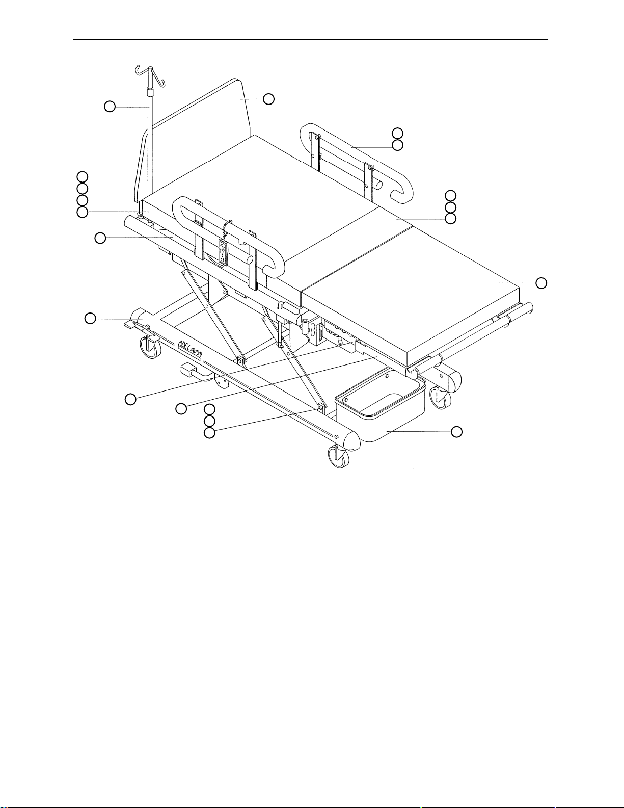
2100–07–00 Bed Assembly
12
19
18
8
9
7
4
1
2
3
21
20
10
5
6
11
17
16
15
13
Item Part No. Part Name Qty.
1 (page 42) Headboard Assembly 1
2 (page 43) Siderail Assembly, Right 1
3 (page 43) Siderail Assembly, Left 1
4 (page 25–26) Base Assembly 1
5 (page 52) Ft. Matt./Push Bar Ass’y1
6 (page 50) Foot Pan Assembly 2
7 (page 29–32) Litter Assembly 1
8 (page 54) Head Section Assembly 1
9 0300–77–00 Overcover 1
10 (page 55) Seat Section Assembly 1
1 1 (page 57) Foot Rest Assembly 2
12 0589–67–00 I.V. Pole Assembly 1
13 1228–01–00 Fluid Basin 1
14 (page 56) Hand Crank (not shown) 1
15 0301–52–00 Groove Pin 4
16 0301–46–00 Flat Washer 4
17 0301–43–00 Retaining Ring 4
18 0306–48–00 But. Hd. Soc. Screw 8
19 0025–07–00 Internal Tooth Lock Washer 8
20 0022–14–00 Pan Head Screw 4
21 0025–02–00 Internal Tooth Lock Washer 4
24
Page 28
16
24
18
28
15
14
13
5
4
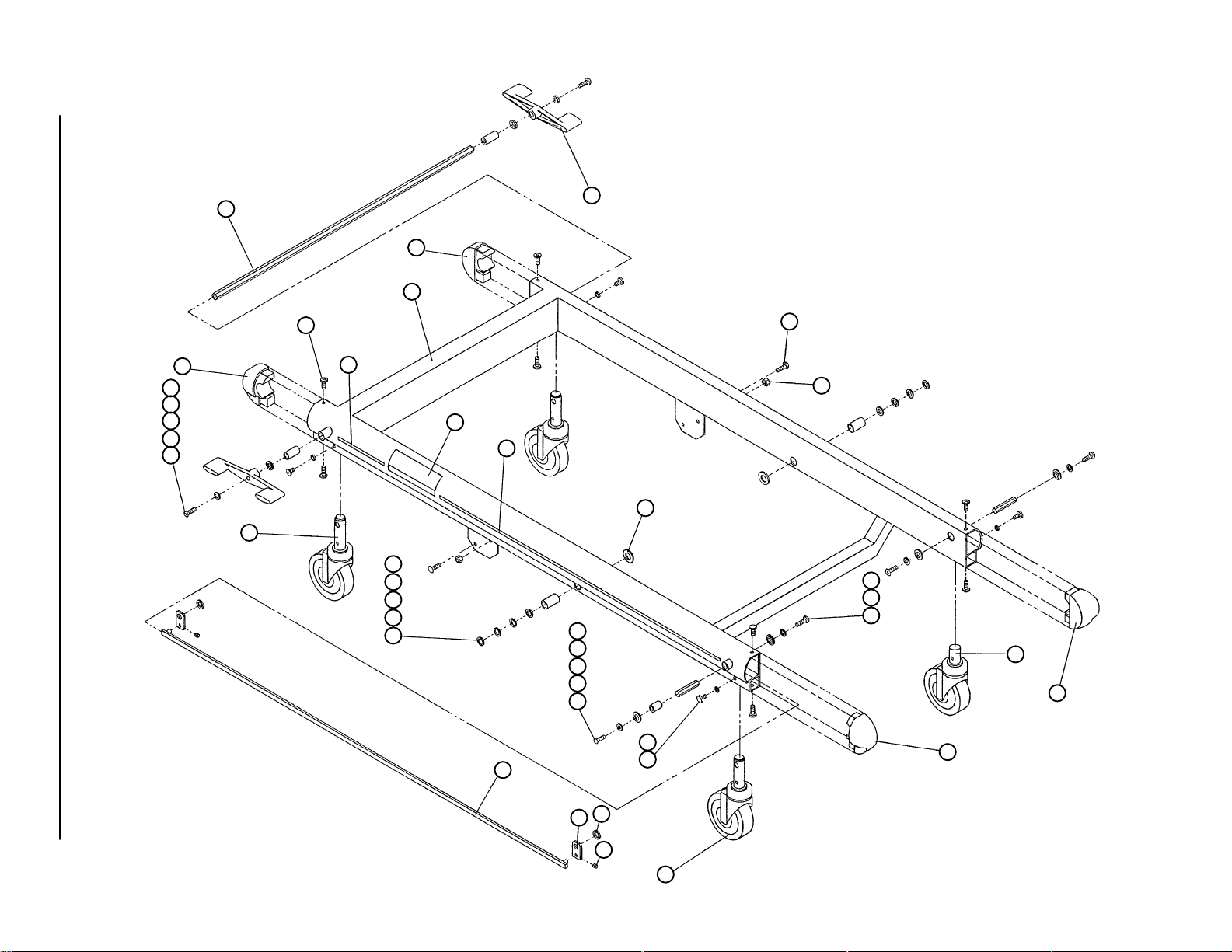
0318–66–00 Base Assembly
17
25
19
20
19
27
26
25
21
12
11
10
10
10
9
29
8
7
6
5
4
3
2
6
5
4
45
25
24
31
30
32
1
Page 29

0318–66–00 Base Assembly
Item Part No. Part Name Qty.
1 0301–22–00 Caster, Brake 2
2 0022–18–00 Ph. Pan Hd. Screw 4
3 0177–00–00 Int. Tooth Lock Washer 4
4 0022–24–00 Ph. Truss Hd. Screw 6
5 0601–24–00 Washer 6
6 0601–16–00 Nylon Bushing 4
7 3978–96–00 Front Bushing 1
8 3978–98–00 Front Shaft 2
9 0610–24–00 Retaining Ring 2
10 0310–50–00 Washer 6
11 0310–52–00 Bushing 2
12 0301–23–00 Caster, Brake/Steer 1
13 0318–64–00 Pedal Assembly, Left 1
14 0025–10–00 Flat Washer 2
15 0316–29–00 Rear Bushing 2
16 3978–99–00 Rear Shaft 1
17 1113–11–00 Screw 8
18 0316–32–00 Chassis Weldment 1
19 0305–03–00 Long Stripe Label 1
20 0310–01–00 Adel 2100 Label 2
21 0310–49–00 Steel Washer 2
24 3979–01–00 Chassis Cap, Right 2
25 3979–00–00 Chassis Cap, Left 2
26 0024–02–00 Nut 4
27 0306–73–00 But. Hd. Screw 4
28 0318–65–00 Pedal Assembly, Right 1
29 0304–88–00 Tie Bar 1
30 0304–83–00 Link 2
31 0602–43–00 Flat Washer 2
32 3978–71–00 Set Screw 2
34 (page 28) Tilt Arm Assembly, Right 1
35 0306–76–00 Spring Bracket, Right 1
36 3978–75–00 Washer 4
37 (page 28) Tilt Lever Assembly 1
38 0310–58–00 Spacer 2
39 0310–45–00 Pedal Pin 2
40 0310–48–00 Nylon Washer 4
41 0306–75–00 Spring Bracket, Left 1
42 0316–18–00 Gas Spring 2
43 0310–53–00 Shoulder Screw 2
44 (page 28) Tilt Arm Assembly, Left 1
45 0301–72–00 Swivel Caster 1
26
Page 30
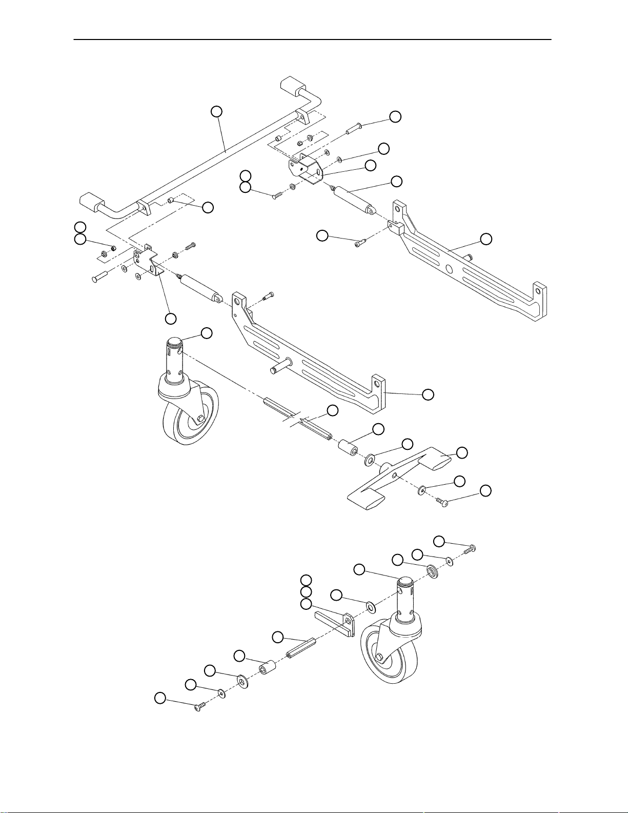
0318–66–00 Base Assembly
37
36
27
38
36
26
35
1
43
16
39
40
41
42
44
34
14
13
5
1
32
30
31
29
8
7
6
5
4
6
28
5
4
4
27
Page 31
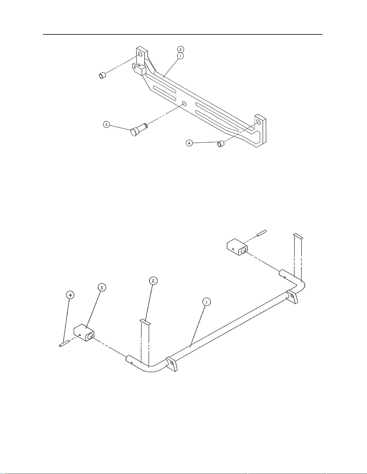
0307–24/25–00 Tilt Arm Assembly, Left & Right
0310–79–00 Tilt Lever Assembly
(Left Side is Shown)
Item Part No. Part Name Qty.
1 0306–79–00 Machined Tilt Arm, Left 1
2 0306–80–00 Machined Tilt Arm, Right 1
3 0310–44–00 Tilt Arm Pin 1
4 0301–36–00 Bronze Bushing 2
Item Part No. Part Name Qty.
1 0310–41–00 Tilt Lever 1
2 0608–22–00 ”Tilt” Label 2
3 0602–49–00 Pedal 2
4 0610–22–00 Spring Pin 2
28
Page 32
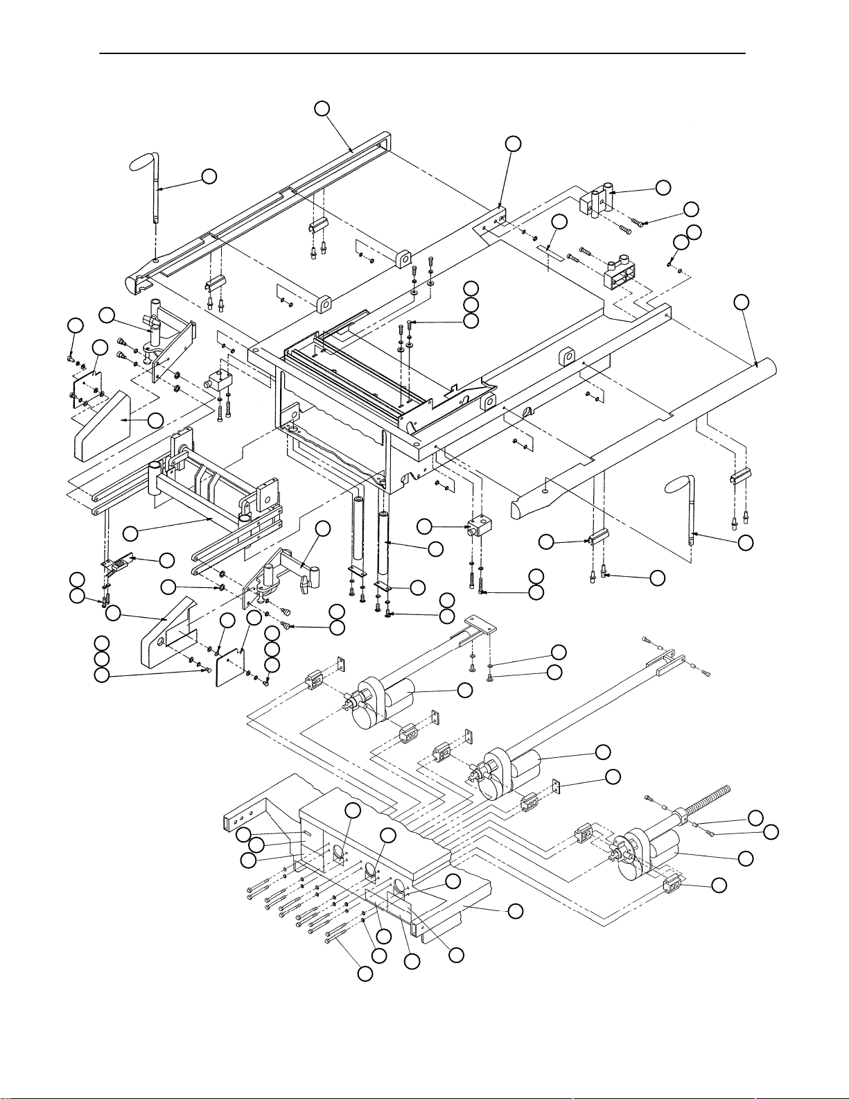
0307–64–00 Litter Assembly
22
25
122
21
121
24
20
125
19
18
116
29
92
16
15
7
14
17
123
124
12
7
122
13
12
11
10
8
5
23
9
7
6
60
3
5
4
5
61
26
27
29
28
30
1
2
62
63
74
77
76
75
73
72
25
69
7
68
70
71
64
65
66
67
29
Page 33
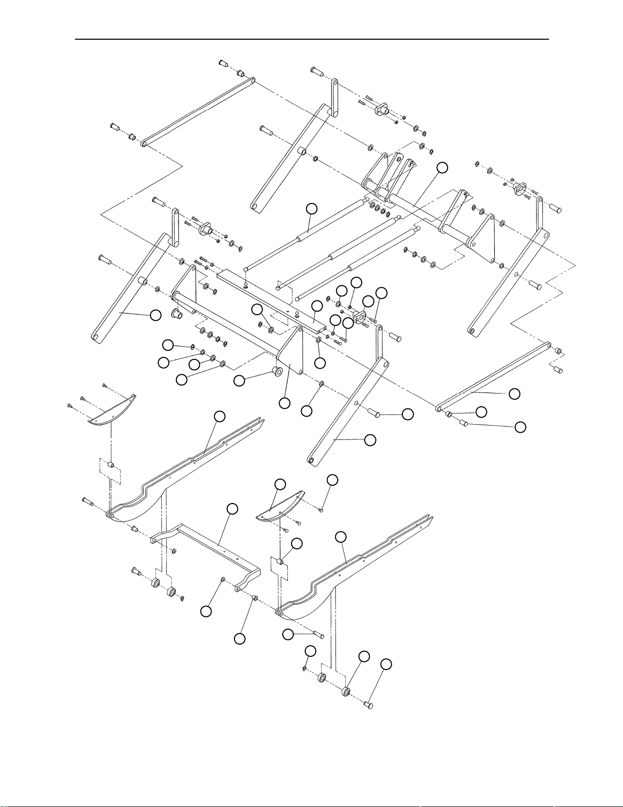
0307–64–00 Litter Assembly
47
41
39
48
46
39
42
5
43
44
45
40
36
39
39
54
38
37
59
58
57
53
52
39
33
36
35
14
55
56
40
51
34
50
32
31
30
Page 34

0307–64–00 Litter Assembly
Item Part No. Part Name Qty. Item Part No. Part Name Qty.
1 (page 33) Hand Grip Ass’y, Lt. 1 62 ** Foot Motor Assembly 1
2 0173–09–00 Pop Rivet 8 63 011 1–01–00 Trunnion Plate 4
3 0573–02–00 I.V. Pole Clip 4 64 0591–04–00 Sleeve Bolt Spacer 4
4 3978–55–00 Screw 4 65 0591–05–00 Soc. Hd. Cap Screw 4
5 0025–09–00 Int. Th. Lock Washer 12 66 ** Lift Motor Assembly 1
6 0023–04–00 Hex Hd. Cap Screw 4 67 0306–96–00 Motor Mount 6
7 0025–07–00 Int. Th. Lock Washer 20 68 0301–60–00 Hex Hd. Screw 12
8 1234–00–00 Retainer Bar 2 69 0315–08–00 Crank Label 1
9 0303–47–00 Foot Pan Guide Shaft 2 70 0199–00–00 Crank Caution Label 1
10 (page 33) Hand Grip Hsg. Ass’y 2 71 0141–00–00 French Caution Label 1
11 0301–62–00 Shoulder Screw 4 72 0305–06–00 Bed Crank Dir. Label 1
12 0318–19–00 Shim 4 73 0305–07–00 Ft. Crank Dir. Label 1
13 (page 34) Ft. Pan Mnt. Ass’y, Lt. 1 74 0305–05–00 Hd. Crank Dir. Label 1
14 1501–78–00 But. Hd. Soc. Screw 8 75 1131–28–00 Shock Caution Label 1
15 0601–24–00 Washer 4 76 0305–00–00 Serial Number Label 1
16 0309–91–00 Ft. Pan Mnt. Cover, L t . 1 77 0084–07–00 Numerical Label 1
17 0310–08–00 Washer 4 78 1500–56–00 Int. Th. Lock Washer 3
18 (page 35) Foot Lift Ass’y 1 79 ** PC Board 1
19 0309–92–00 Ft. Pan Mnt. Cover, Rt. 1 80 0307–28–00 Cir. Bd. Cover Ass’y1
20 (page 34) Ft. Pan Mnt. Ass’y, Rt. 1 81 3978–42–00 Lock Washer 2
21 (page 33) Hand Grip Ass’y, Rt. 1 82 1501–43–00 Screw 2
22 3978–51–00 Litter Bumper, Rt. 1 83 0023–24–00 Pan Hd. Tap. Screw 2
23 3978–45–00 Soc. Hd. Screw 4 84 0024–18–00 Nut 5
24 0549–00–00 Flat Washer 4 85 0306–50–00 Shield 1
25 3978–65–00 Litter Weldment 1 86 3979–25–00 Junction Box 1
26 3978–39–00 Headboard Mount 2 87 0306–74–00 Cable Clamp 4
27 3978–63–00 Soc. Screw 4 88 0315–05–00 Elec./Pneu. Schematic 1
28 0306–68–00 Hex Nut 11 89 0306–51–00 Cable Clamp 2
29 0025–02–00 Int. Th. Lock Washer 22 90 0300–09–00** Compressor Assembly 1
30 3978–50–00 Litter Bumper, L t . 1 91 0300–06–00** Manifold Assembly 1
31 0301–50–00 Groove Pin 4 92 0022–14–00 Pan Hd. Screw 4
32 0301–35–00 Flange Bushing 4 96 0046–15–00 Cable Clip 15
33 0301–28–00 Lift Link 2 98 0046–00–00 Cable Clamp 1
34 0301–53–00 Groove Pin 8 99 0300–05–00** Hand Pendant 1
35 (page 36) Lift Bar Ass’y, Lt. 2 100 0310–02–00 #4 Wire Label 1
36 0301–46–00 Flat Washer 8 101 0306–59–00 Gasket 6
37 0306–72–00 Slave Crank 1 102 1500–39–00 Hex Nut 3
38 0301–40–00 Flange Bushing 2 103 0300–70–00 Compressor Cable 1
39 0602–54–00 Flat Washer 20 104 0310–05–00 #7 Wire Label 1
40 0301–43–00 Retaining Ring 12 105 0300–61–00 Solenoid Cable Ass’y3
41 (page 36) Lift Bar Ass’y, Rt. 2 106 0310–04–00 #6 Wire Label 1
42 0307–26–00 Gas Spring Bar 1 107 0310–03–00 #5 Wire Label 1
43 0306–73–00 Screw 4 108 1132–17–00 Standoff 2
44 0608–19–00 Screw 8 109 1500–14–00 Strain Relief 1
45 0303–89–00* Bushing 4 110 3979–27–00 Interconnect Cable 1
46 0024–01–00 Hex Lock Nut 8 111 3979–22–00 Strain Relief 2
47 0303–64–00 Gas Spring 3 112 3979–41–00 Ground. Symbol Label 1
48 (page 37) Drive Crank Ass’y 1 113 3979–23–00 Conduit Lock Nut 2
49 0850–02–00 Gas Spring Ret. Clip 6 114 3979–24–00 Cover 1
50 0302–92–00 Roller Guide Pin 2 115 3979–26–00 Power Cord 1
51 0607–14–00 Ball Bearing 4 116 (page 38) Limit Switch Assembly 1
52 0302–93–00 Head Panel Pin 2 117 1229–00–00 Basin Holder Button 2
53 0303–79–00 Flange Bushing 2 118 0022–21–00 Pan Hd. Slot. Screw 2
54 0164–00–00 Retaining Ring 2 119 0305–23–00 Basin Caution Label 1
55 0303–20–00 Caged Roller 2 120 0590–77–00 Control Warning Label 1
56 0303–99–00 Head Panel Frame, Lt. 1 121 0309–01–00 Label, Pendant Caution 1
57 3978–73–00 Pull Bar, Head 1 122 0022–24–00 Screw 2
58 0303–33–00 Head Panel Wear Plate 2 123 0309–93–00 Ft. Pan Mt. Cov. Plate, Lt. 1
59 0303–98–00 Hd. Panel Frame, Rt. 1 124 0305–15–00 Washer 4
60 ** Head Motor Assembly 1 125 0309–94–00 Ft. Pan Mt. Cov. Plate, Rt. 1
61 3979–37–00 Hex Hd. Screw 2
* Item # 45: use p/n 307–63–00 for Lift Bushing Kit.
** Refer to page 22, Field Replacement Parts, for correct replacement part number or kit part number.
31
Page 35
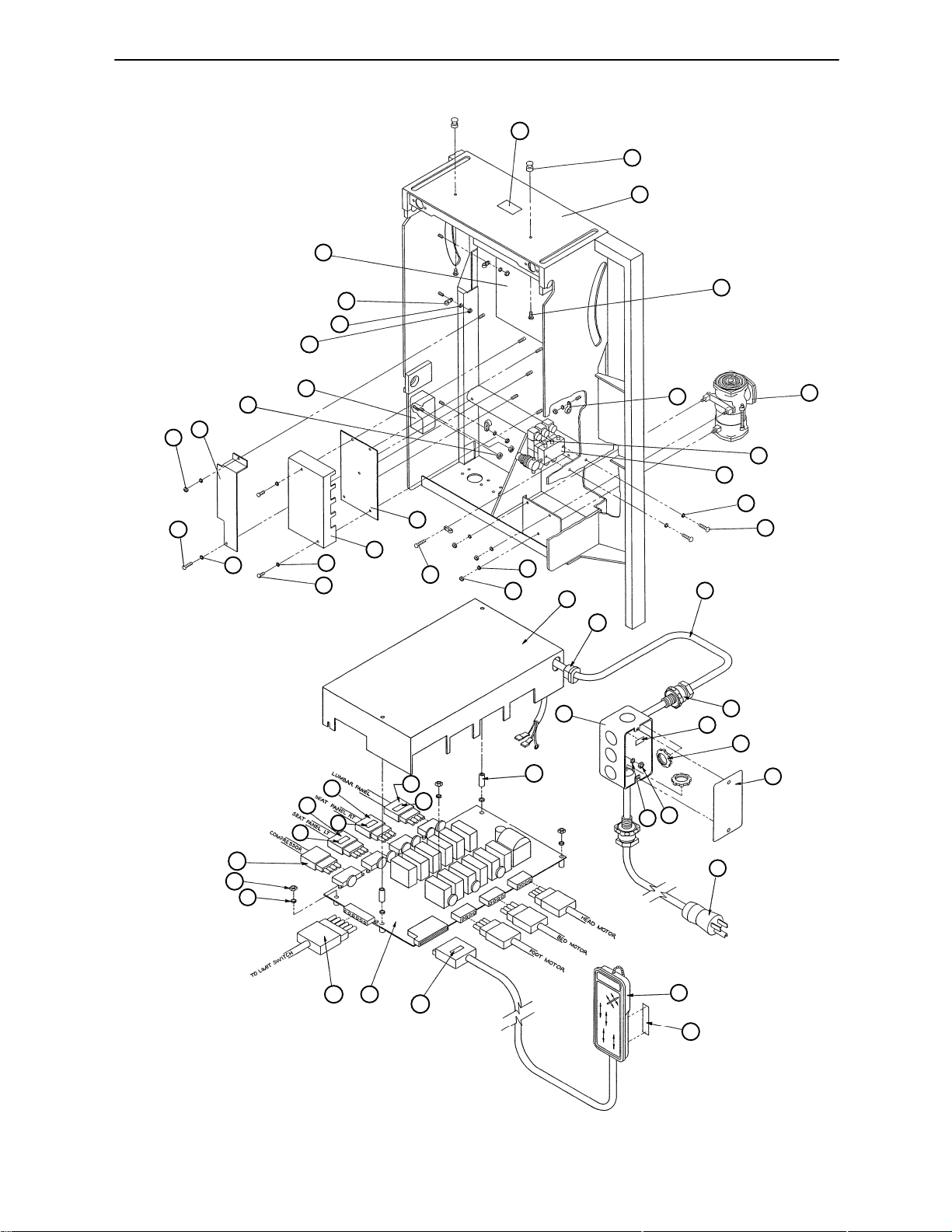
0307–64–00 Litter Assembly
88
119
117
25
87
118
29
84
86
46
85
84
89
101
90
91
29
83
79
92
80
29
81
82
83
78
28
80
109
86
110
111
112
113
103
102
104
105
105
106
105
107
108
84
29
115
114
29
116
79
100
99
120
32
Page 36
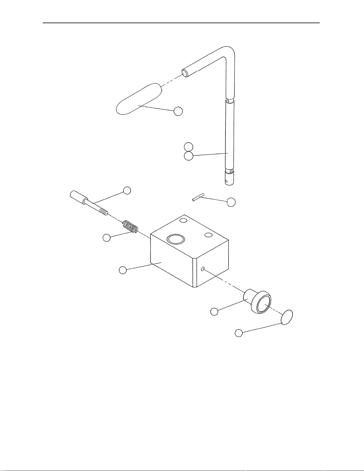
(Left Side is Shown)
3978–53/54–00 Handgrip Assembly
3
2
1
9
4
8
7
6
5
Item Part No. Part Name Qty.
1 3978–60–00 Hand Grip, Left 1
2 3978–61–00 Hand Grip, Right 1
3 0304–23–00 Hand Grip 1
4 3978–57–00 Driv–Loc Pin 1
5 0315–03–00 Pull Label 1
6 0041–06–00 Pull Knob 1
7 3978–59–00 Hand Grip Housing 1
8 1029–06–00 Foot Latch Spring 1
9 3978–56–00 Latch Pin 1
33
Page 37
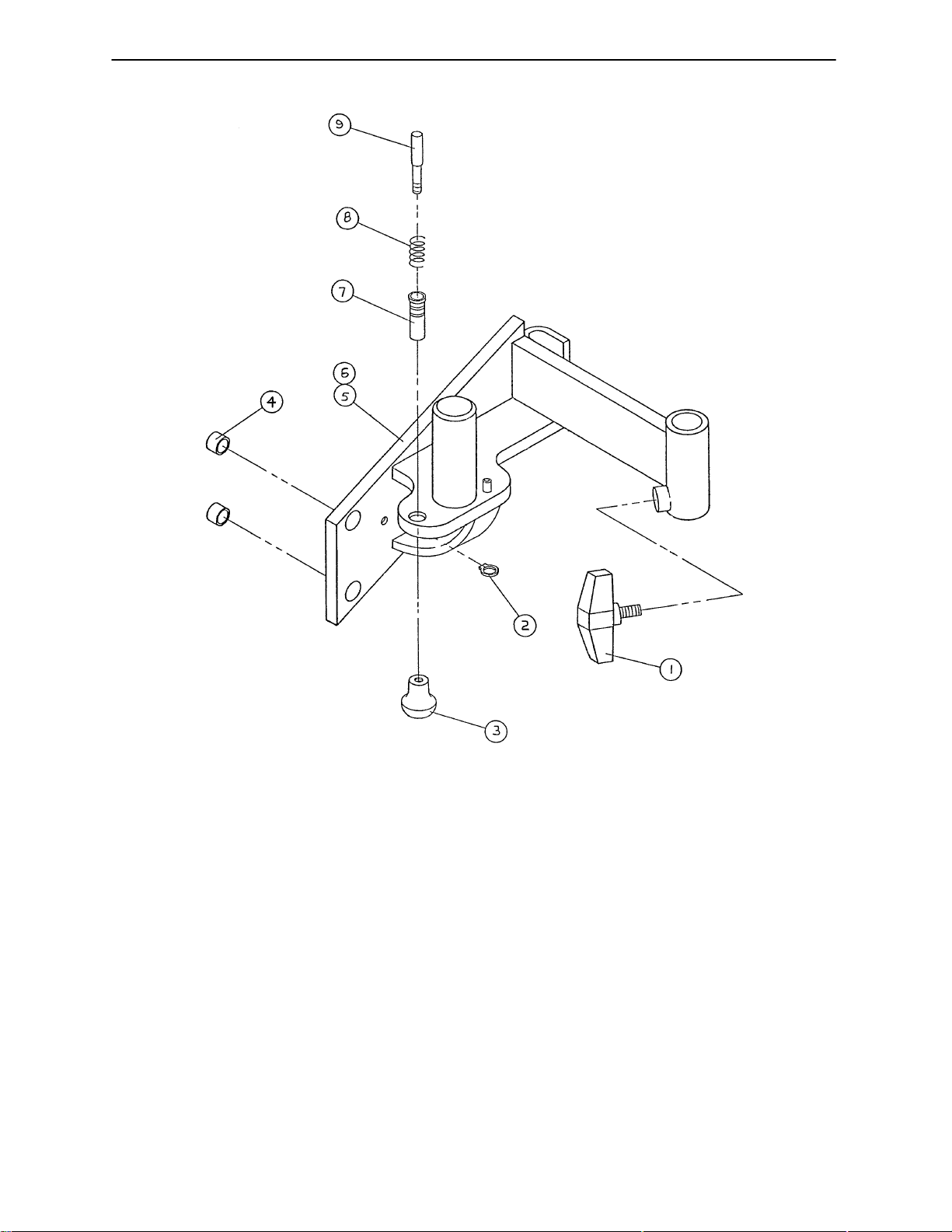
0307–67/68–00 Foot Pan Mount Ass’y, Left & Right
(Left Side is Shown)
Item Part No. Part Name Qty.
1 1141–03–00 T–Knob 1
2 0020–11–00 Retaining Ring 1
3 0041–06–00 Pull Knob 1
4 0310–09–00 Bearing 2
5 0307–47–00 Foot Pan Mount, Lt. 1
6 0307–48–00 Foot Pan Mount, Rt. 1
7 1307–00–00 Foot Panel Hsg. Latch 1
8 1029–06–00 Foot Latch Spring 1
9 1307–01–00 Foot Panel Latch Spring 1
34
Page 38
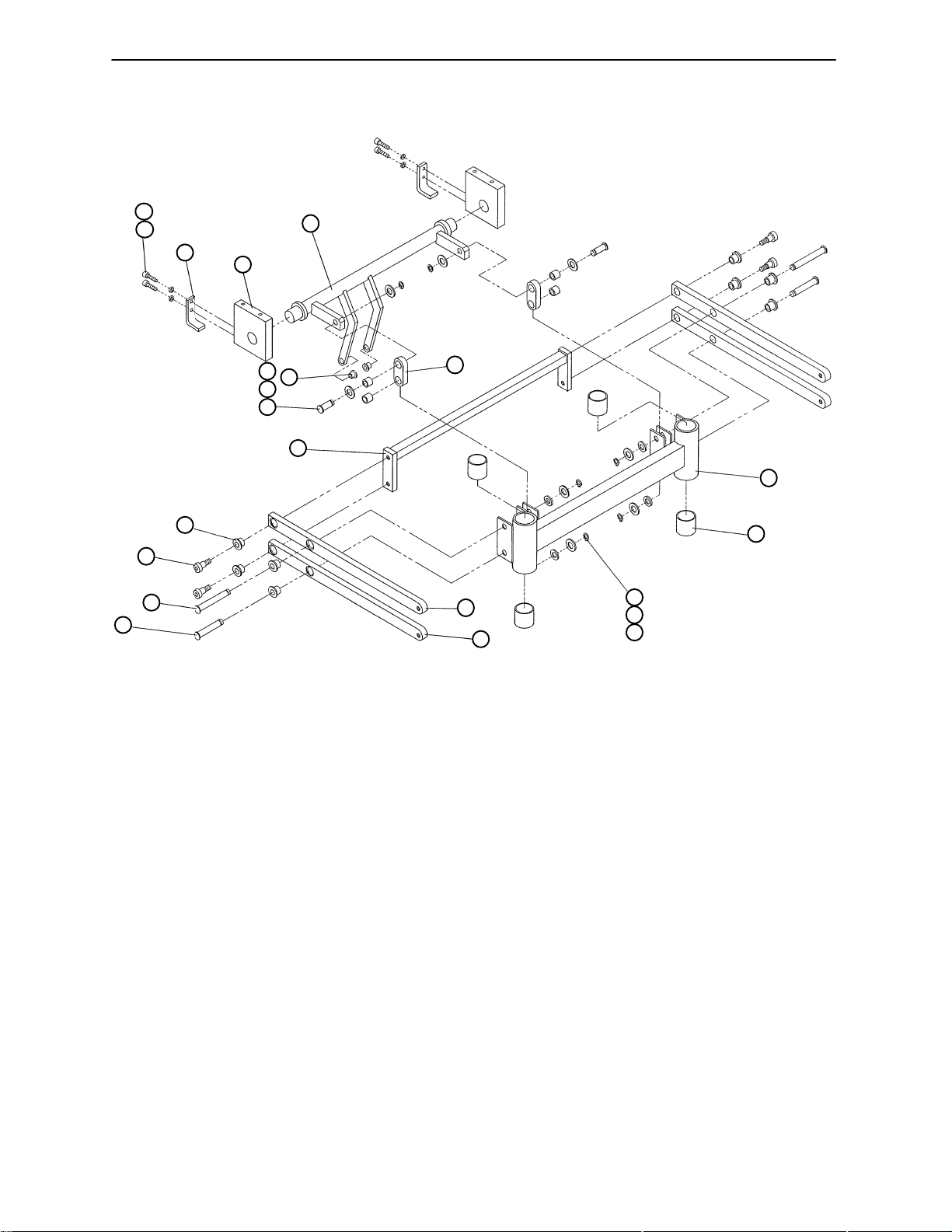
0300–13–00 Foot Lift Assembly
21
20
19
11
10
9
8
18
17
15
16
4
14
12
13
1
2
7
6
5
4
3
Item Part No. Part Name Qty.
1 0303–37–00 Foot Lift Bar 1
2 0021–04–00 Bushing 4
3 0301–42–00 Retaining Ring 6
4 0602–43–00 Flat Washer 8
5 0301–59–00 Flat Washer 4
6 0310–11–00 Foot Pan Lift Arm 1
7 0303–39–00 Foot Pan Link Arm 3
8 0301–49–00 Pin 2
9 0301–48–00 Pin 2
10 0301–45–00 Shoulder Screw 4
11 0301–39–00 Flange Bushing 8
12 0303–42–00 Slide Bar 1
13 0303–36–00 Foot Lift Link 2
14 0301–47–00 Pin 2
15 0301–38–00 Bronze Bushing 4
16 0021–01–00 Flange Bushing 2
17 0306–71–00 Foot Crank 1
18 0303–65–00 Bearing Block 2
19 0303–78–00 Stop Bracket 2
20 0025–07–00 Int. Th. Lock Washer 4
21 0301–61–00 Soc. Screw 4
35
Page 39
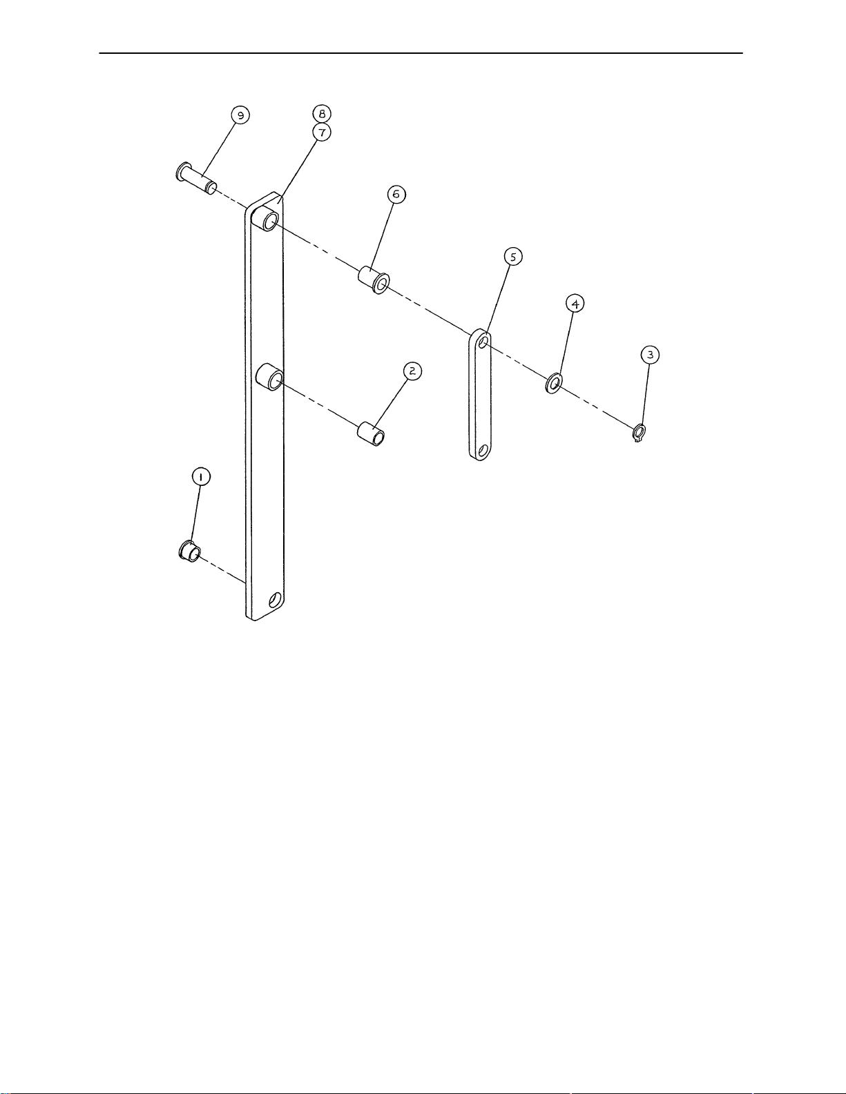
0301–70/71–00 Lift Bar Assembly, Left & Right
(Left Side is Shown)
Item Part No. Part Name Qty.
1 0301–35–00 Flange Bushing 1
2 0318–91–00 Bushing 1
3 0301–43–00 Retaining Ring 1
4 0602–54–00 Flat Washer 1
5 0301–01–00 Idle Link 1
6 0301–37–00 Flange Bushing 1
7 0301–63–00 Lift Bar, Left 1
8 0301–64–00 Lift Bar, Right 1
9 0301–53–00 Groove Pin 1
36
Page 40
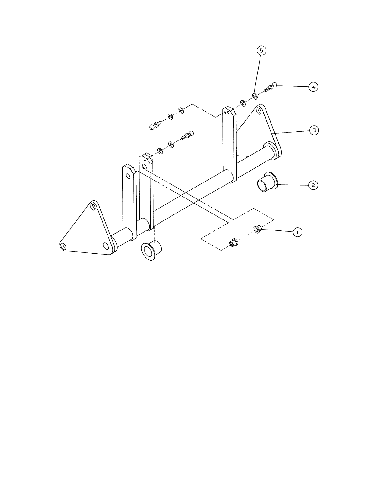
0307–27–00 Drive Crank Assembly
Item Part No. Part Name Qty.
1 0021–01–00 Flange Bushing 2
2 0310–12–00 Flange Bushing 2
3 0303–45–00 Drive Crank 1
4 0850–01–00 Gas Spring Ball Stud 3
5 0025–09–00 Int. Th. Lock Washer 6
37
Page 41
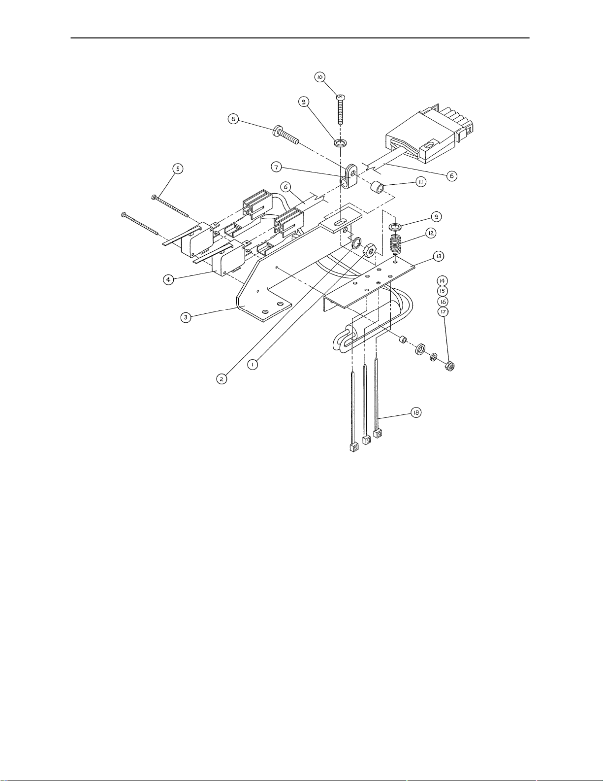
0300–04–00 Limit Switch Assembly*
Item Part No. Part Name Qty.
1 0024–18–00 Nut 1
2 0025–02–00 Int. Th. Lock Washer 1
3 0032–01–00 Switch Bracket 1
4 0306–22–00 Micro Switch 2
5 0032–08–00 Pan Hd. Phillips Screw 2
6 0306–99–00 Limit Switch Cable Ass’y1
7 0306–74–00 Cable Clamp 1
8 0023–34–00 Screw 1
9 1501–48–00 Flat Washer 2
10 1501–84–00 Screw 1
11 3979–28–00 Spacer 1
12 0032–03–00 Coil Spring 1
13 0032–00–00 Pivot Bracket 1
14 0032–04–00 Spacer 1
15 0032–05–00 Nylon Washer 1
16 0032–06–00 Flat Washer 1
17 0032–07–00 Locking Nut 1
18 1502–56–00 Cable Tie 3
* Refer to page 22, Field Replacement Parts for correct part number.
38
Page 42
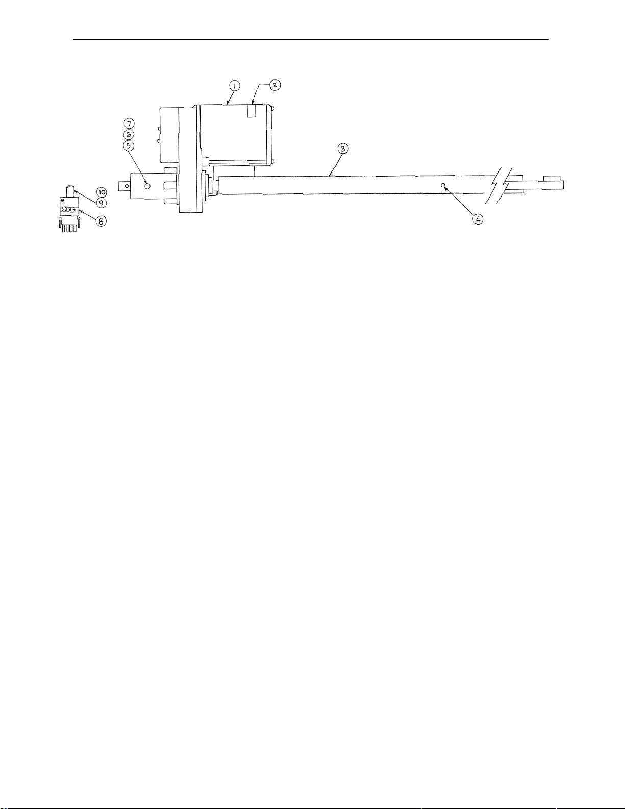
3979–17–00 Head Motor Assembly*
Item Part No. Part Name Qty.
1 0310–07–03 Head Motor, Machined 1
2 1076–06–00 Motor Serial # Label 1
3 3978–72–00 Drive Tube, Head 1
4 0161–01–00 Roll Pin 1
5 3979–21–00 Trunnion Mount 2
6 0023–04–00 Hex Hd. Cap Screw 2
7 0025–07–00 Int. Tooth Lock Washer 2
8 0084–03–00 #3 Wire Label 1
9 0046–00–00 Cable Clamp 1
10 0023–24–00 Pan Hd. Tapping Screw 1
* Refer to Field Replacement Parts (page 22) for correct replacement part number.
39
Page 43
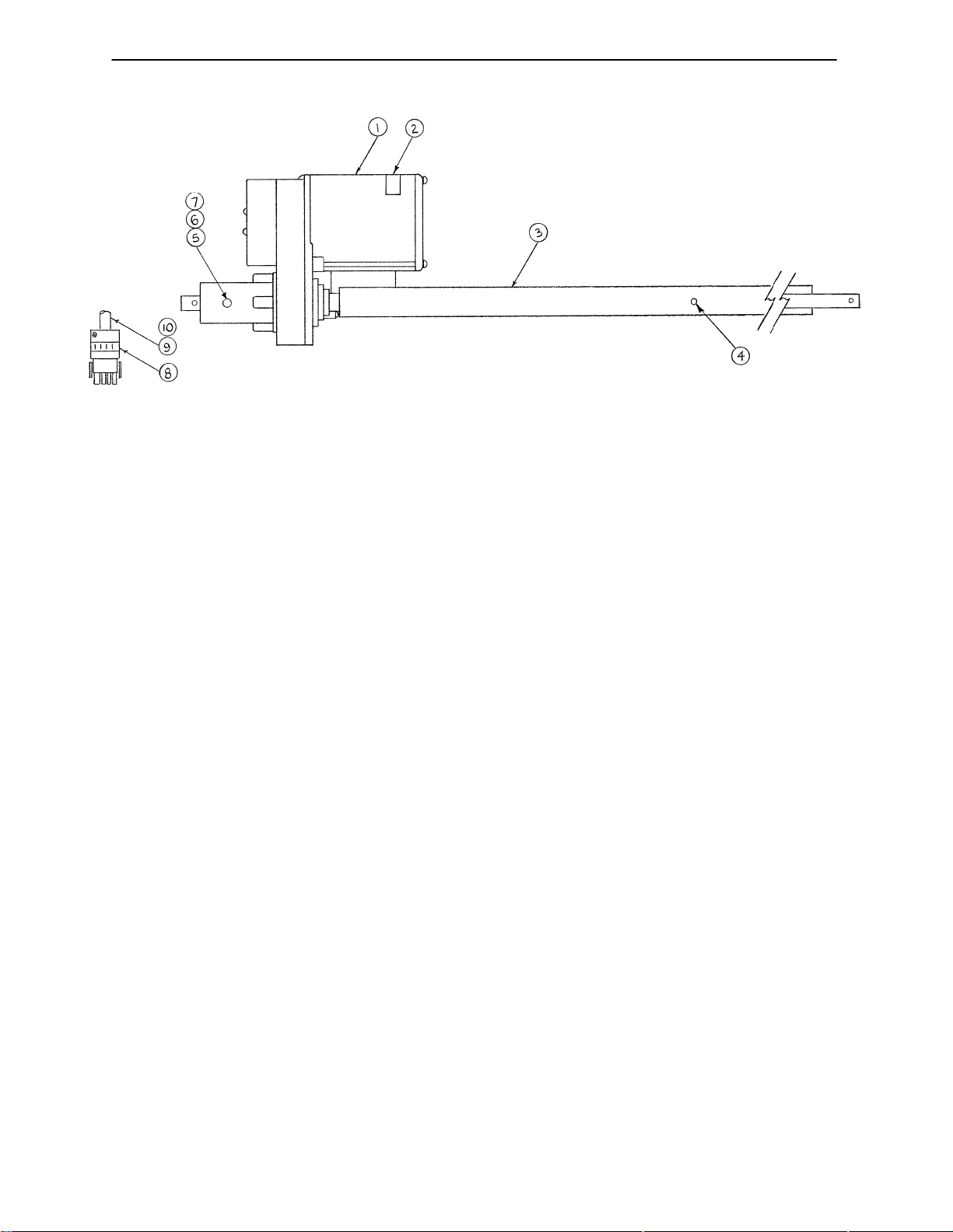
0310–10–00 Foot Motor Assembly*
Item Part No. Part Name Qty.
1 0310–10–03 Foot Motor, Machined 1
2 1076–06–00 Motor Serial # Label 1
3 0303–60–00 Drive Tube, Foot 1
4 0161–02–00 Roll Pin 1
5 3979–21–00 Trunnion Mount 2
6 0023–04–00 Hex Hd. Cap Screw 2
7 0025–07–00 Int. Tooth Lock Washer 2
8 0084–01–00 #1 Wire Label 1
9 0046–00–00 Cable Clamp 1
10 0023–24–00 Pan Hd. Tapping Screw 1
* Refer to Field Replacement Parts (page 22) for correct replacement part number.
40
Page 44
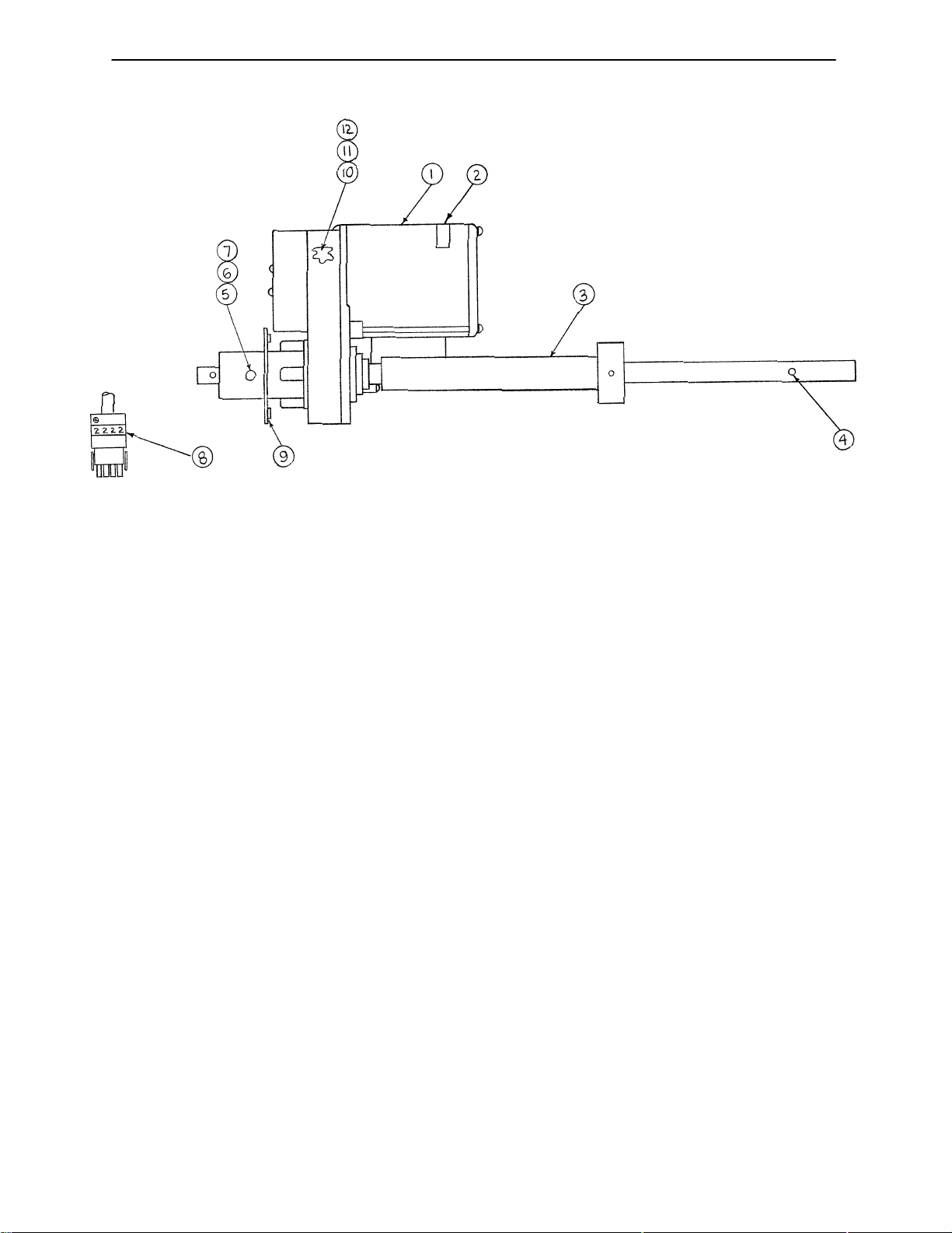
0310–13–00 Lift Motor Assembly*
Item Part No. Part Name Qty.
1 0310–13–03 Lift Motor, Machined 1
2 1076–06–00 Motor Serial # Label 1
3 0303–58–00 Bed Drive Tube 1
4 0161–01–00 Roll Pin 1
5 3979–21–00 Trunnion Mount 2
6 0023–04–00 Hex Hd. Cap Screw 2
7 0025–07–00 Int. Tooth Lock Washer 2
8 0084–02–00 #2 Wire Label 1
9 0302–45–00 Trunnion Plate 1
10 0301–67–00 Pinion Gear 1
11 0301–68–00 Powdered Metal Gear 1
12 0301–69–00 Gear Bushing 2
* Refer to Field Replacement Parts (page 22) for correct replacement part number.
41
Page 45
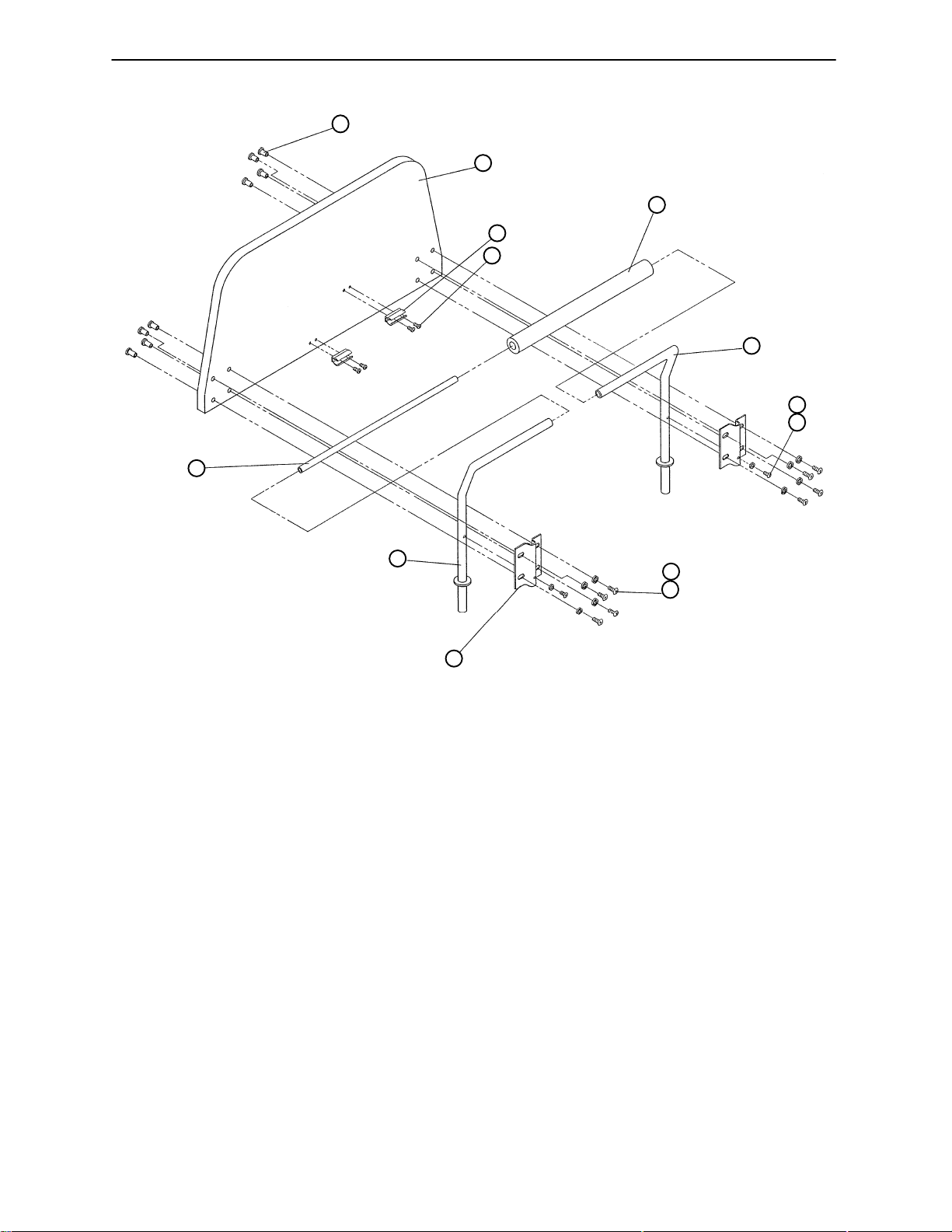
0304–82–00 Headboard Assembly
1
2
3
4
13
5
6
8
7
12
11
10
9
Item Part No. Part Name Qty.
1 0834–01–00 Conn. Joint Cap 8
2 0863–00–00 Headboard 1
3 2206–00–00 Hand Crank Clip 2
4 3979–19–00 Shim Screw 4
5 0589–90–00 Foam Cover 1
6 3978–69–00 Push Bar, Right 1
7 0022–00–00 Pan Head Screw 2
8 0025–02–00 Int. Th. Lock Washer 2
9 0022–24–00 Screw 8
10 0025–05–00 Flat Washer 8
11 0526–06–00 Headboard Mtg. Brkt. 2
12 3978–70–00 Push Bar, Left 1
13 3978–47–00 Push Tube Handle 1
42
Page 46
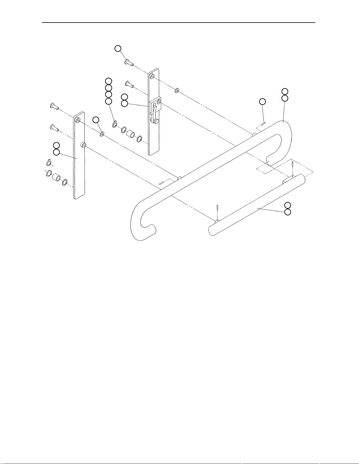
0304–79/80–00 Siderail Assembly, Left & Right
9
(Left Side is Shown)
5
6
5
8
4
7
3
2
1
10
12
11
Item Part No. Part Name Qty.
1 (page 45) Front Siderail Arm, Lt. 1
2 (page 45) Front Siderail Arm, Rt. 1
3 0025–11–00 Flat Washer 2
4 3978–34–00 Snap Ring 2
5 0304–44–00 Washer 4
6 0304–42–00 Bushing 2
7 (page 44) Rear Siderail Arm, Lt. 1
8 (page 44) Rear Siderail Arm, Rt. 1
9 3978–35–00 Pin 4
10 3978–33–00 Roll Pin 4
11 0304–52–00 Upper Tube, Lt. 1
12 0304–53–00 Upper Tube, Rt. 1
13 0304–51–00 Lower Tube, Lt. 1
14 0304–50–00 Lower Tube, Rt. 1
14
13
43
Page 47
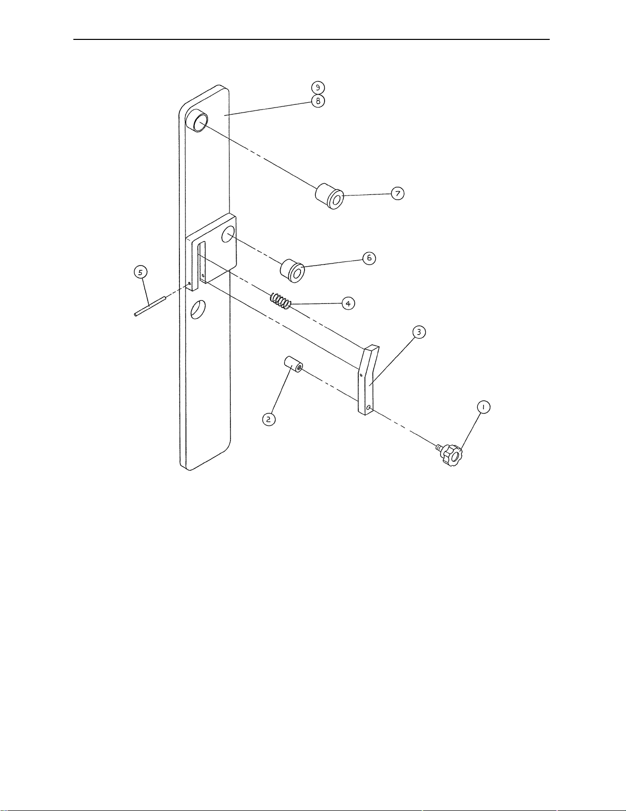
0310–77/78–00 Rear Siderail Arm Ass’y, Left & Right
(Left Side is Shown)
Item Part No. Part Name Qty.
1 3978–52–00 Knob 1
2 0304–41–00 Knob 1
3 0304–11–00 Latch 1
4 0304–47–00 Spring 1
5 0304–22–00 Roll Pin 1
6 0304–43–00 Bushing 1
7 0304–40–00 Bushing 1
8 0304–48–00 Rear Siderail Arm, Lt. 1
9 0304–36–00 Rear Siderail Arm, Rt. 1
44
Page 48
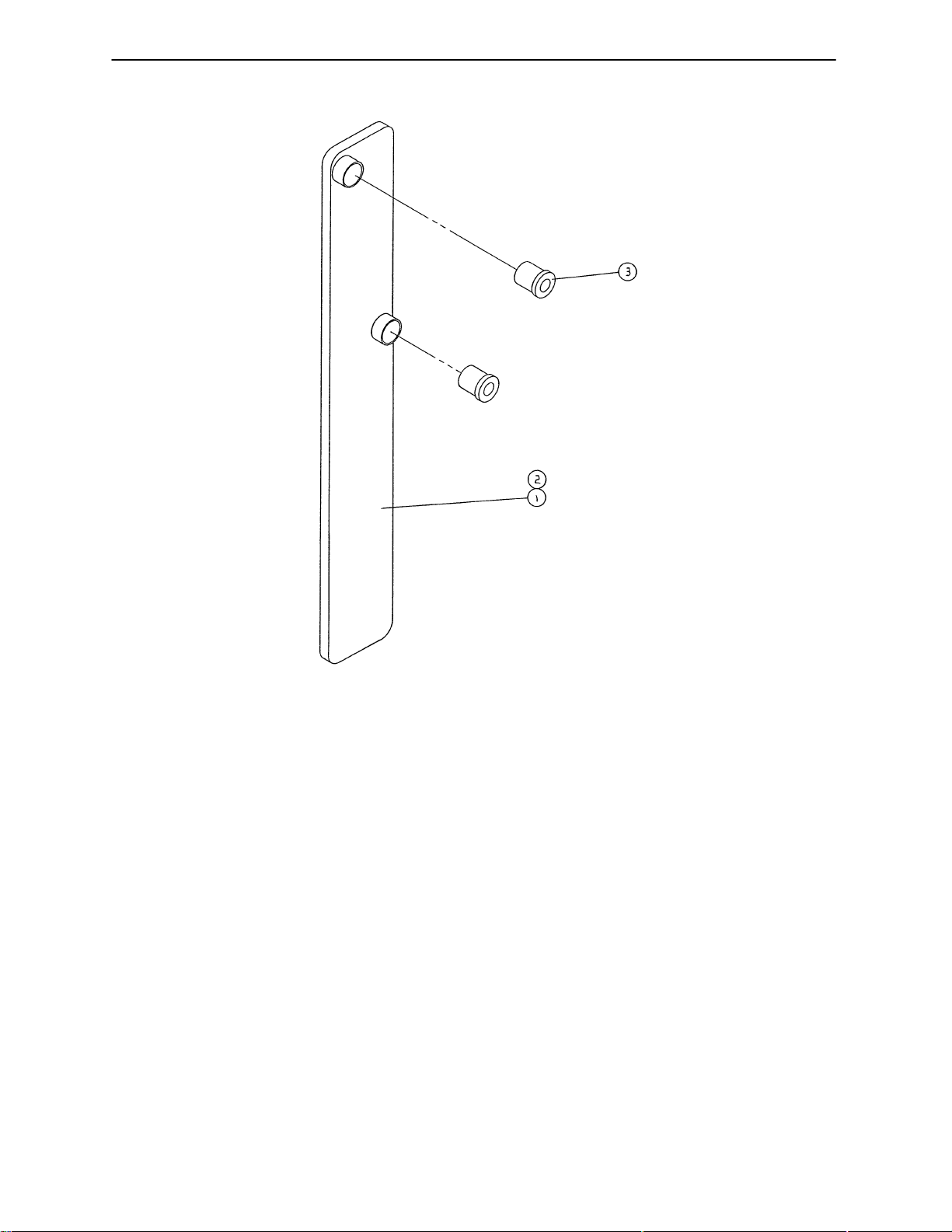
0310–75/76–00 Front Siderail Arm Ass’y, Left & Right
(Left Side is Shown)
Item Part No. Part Name Qty.
1 0304–49–00 Front Siderail Arm, Lt. 1
2 0304–35–00 Front Siderail Arm, Rt. 1
3 0304–40–00 Bushing 2
45
Page 49
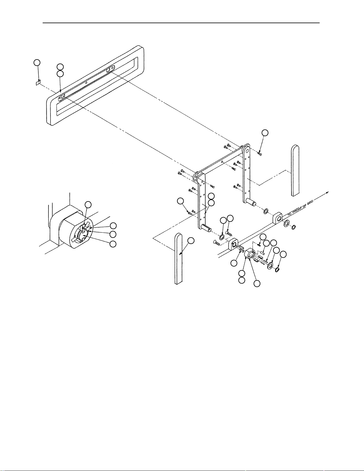
0308–37/38–00 Wood Siderail Assembly, Left & Right
17
16
15
5
4
3
10
DETAIL A
VIEW OF PIVOT BLOCK WITH P ARTS IN PLACE
MINUS ITEM 1, RETAINING RING, AND ITEM 2,
FLA T WASHER.
(Left Side is Shown)
13
14
10
12
11
9
8
5
3
4
2
1
4
6
7
A
Item Part No. Part Name Qty.
1 0308–32–00 Retaining Ring 4
2 0308–33–00 Flat Washer 2
3 0308–35–00 Rubber Dowel 2
4 0308–36–00 Key 5
5 0308–27–00 Pivot Stop Bearing 1
6 0308–26–00 Pivot Stop Housing, Lt. 1
7 0308–25–00 Pivot Stop Housing, Rt. 1
8 0304–44–00 Washer 2
9 0308–34–00 Flat Head Screw 8
10 0308–65–00 Rear Arm Cover 2
11 (page 48) Mounting Bar Ass’y, Lt. 1
12 (page 48) Mounting Bar Ass ’y, Rt. 1
13 0608–19–00 Screw 3
14 0023–32–00 Wood Screw 12
15 0308–13–00 Siderail, Left 1
16 0308–12–00 Siderail, Right 1
17 0315–03–00 Label, Pull 1
46
Page 50
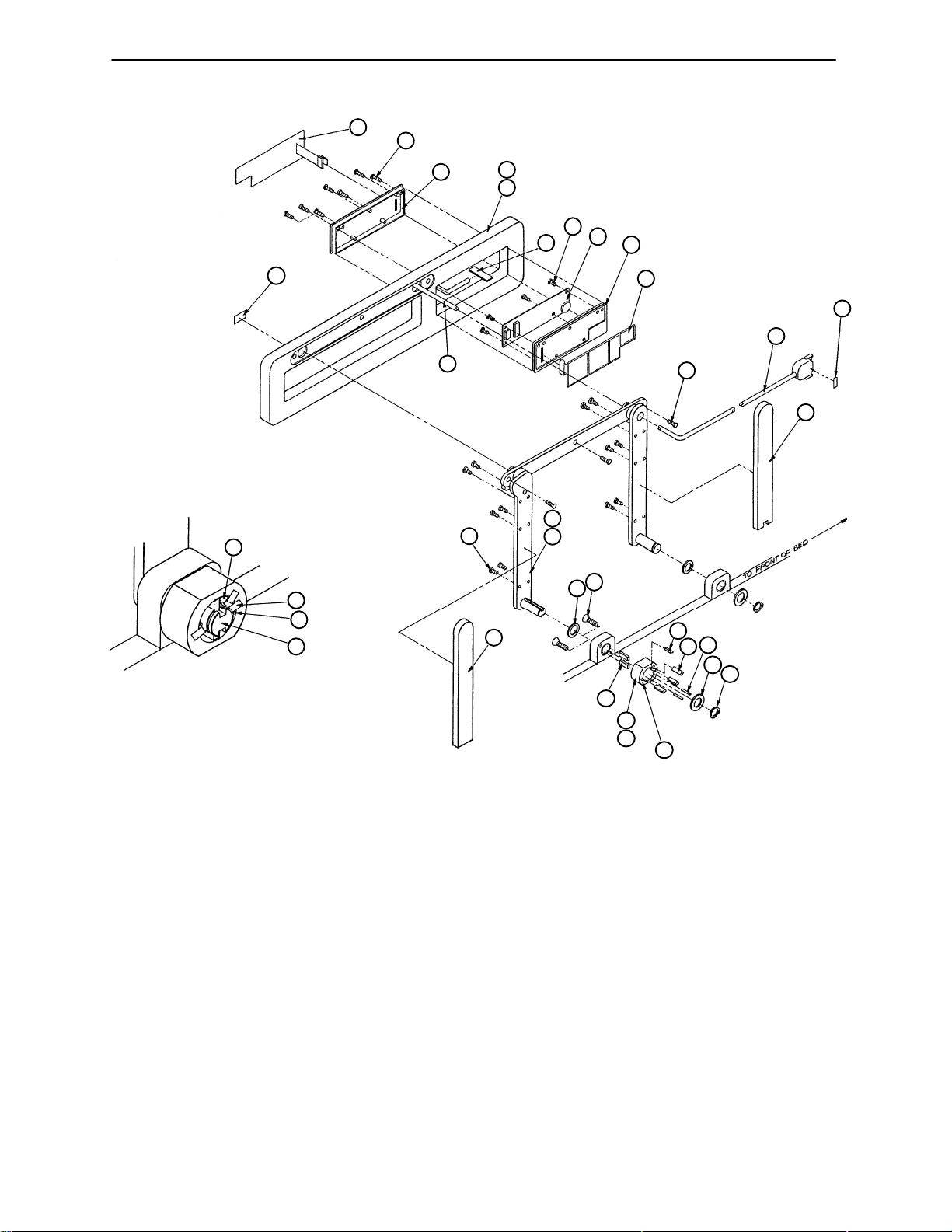
0309–46/47–00 Nurse Comm. Siderail Ass’y, Left & Right
26
27
5
25
24
16
23
22
20
21
14
19
18
17
12
11
(Left Side is Shown)
28
16
13
15
9
4
3
10
DETAIL A
VIEW OF PIVOT BLOCK WITH P ARTS
IN PLACE MINUS ITEM 1, RETAINING
RING, AND ITEM 2, FLAT WASHER
10
8
5
3
4
2
1
4
6
7
A
Item Part No. Part Name Qty. Item Part No. Part Name Qty.
1 0308–32–00 Retaining Ring 2 15 0308–54–00 Arm Cover 1
2 0308–33–00 Flat Washer 2 16 0309–20–00 Siderail Cable Ass’y1
3 0308–35–00 Rubber Dowel 2 17 0309–11–00 Mem. Switch, Pat. Side 1
4 0308–36–00 Key 5 18 0309–14–00 Plastic Hsg., Pat. SIde 1
5 0308–27–00 Pivot Stop Bearing 1 19 0309–12–00 Nurse Comm. PCB 1
6 0308–26–00 Pivot Stop Housing, Lt. 1 20 0024–29–00 Phillips Hd. Screw 4
7 0308–25–00 Pivot Stop Housing, Rt. 1 21 0309–24–00 Nurse Comm. Connect. 1
8 0304–44–00 Washer 2 22 0301–74–00 Siderail, Left 1
9 0308–34–00 Screw 8 23 0301–73–00 Siderail, Right 1
10 0308–65–00 Rear Arm Cover 1 24 0309–13–00 Plastic Hsg., Nurse Side 1
1 1 (page 48) Mounting Bar Ass’y, Lt. 1 25 0024–30–00 Screw 6
12 (page 48) Mounting Bar Ass’y, Rt. 1 26 0309–10–00 Mem. Swch., Nurse Side 1
13 0608–19–00 Screw 3 27 0315–03–00 Label, Pull 1
14 0023–32–00 Wood Screw 12 28 0084–01–00 Label, Wire #1 1
47
Page 51
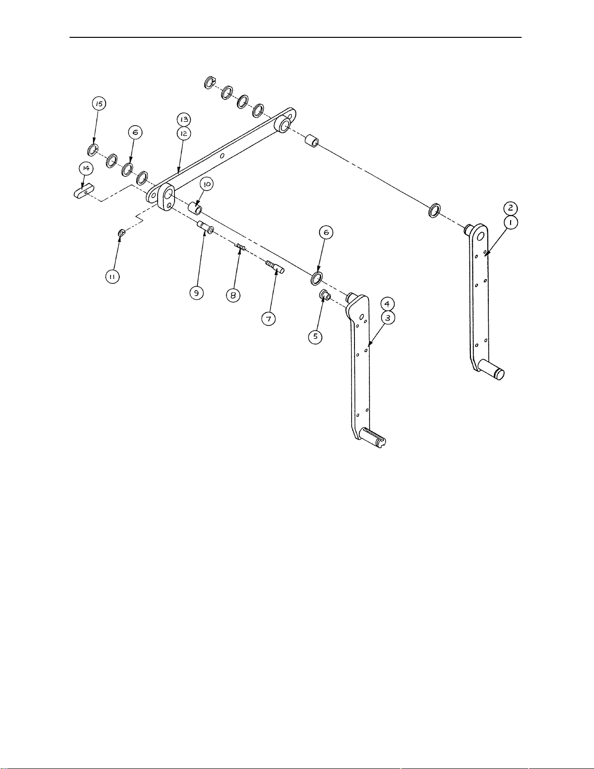
0309–43/44–00 Siderail Mounting Bar Ass’y, Left & Right
(Left Side is Shown)
Item Part No. Part Name Qty.
1 0308–64–00 Front Pivot Arm, Left 1
2 0308–63–00 Front Pivot Arm, Right 1
3 0308–17–00 Rear Pivot Arm, Left 1
4 0308–16–00 Rear Pivot Arm, Right 1
5 0308–20–00 Pin Liner, Modified 1
6 0304–44–00 Washer 8
7 0308–24–00 Plunger, Modified 1
8 1029–06–00 Foot Latch Spring 1
9 0308–23–00 Plunger Hsg., Modified 1
10 0308–30–00 Bushing 2
11 0020–11–00 Retaining Ring 1
12 0308–15–00 Siderail Mtg. Bar, Left 1
13 0308–14–00 Siderail Mtg. Bar, Right 1
14 0318–34–00 Plunger Handle 1
15 0308–32–00 Retaining Ring 2
48
Page 52
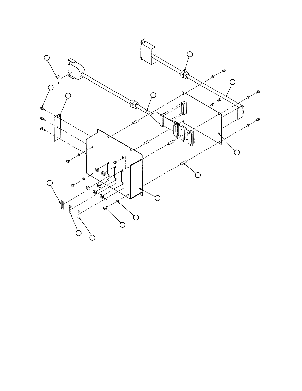
0309–28–00 Splitter Box Assembly
13
6
5
13
8
11
10
9
7
4
3
1
12
12
Item Part No. Part Name Qty.
1 1500–70–00 Round Head Screw 8
2 0309–27–00 Rear Mount Latching Block 6
3 1500–55–00 Internal Tooth Lock Washer 8
4 0309–19–00 Splitter Box 1
5 0309–26–00 Splitter Box Plate 1
6 0306–02–00 Phillips Head Screw 3
7 1501–44–00 Round Threaded Spacer 4
8 0309–23–00 Splitter Cable Assembly 1
9 0309–17–00 Splitter PCB 1
10 0309–21–00 Bed Cable Assembly 1
11 1500–14–00 Strain Relief 2
12 0084–01–00 Label, Wire #1 2
13 0310–02–00 Label, Wire #4 2
49
Page 53
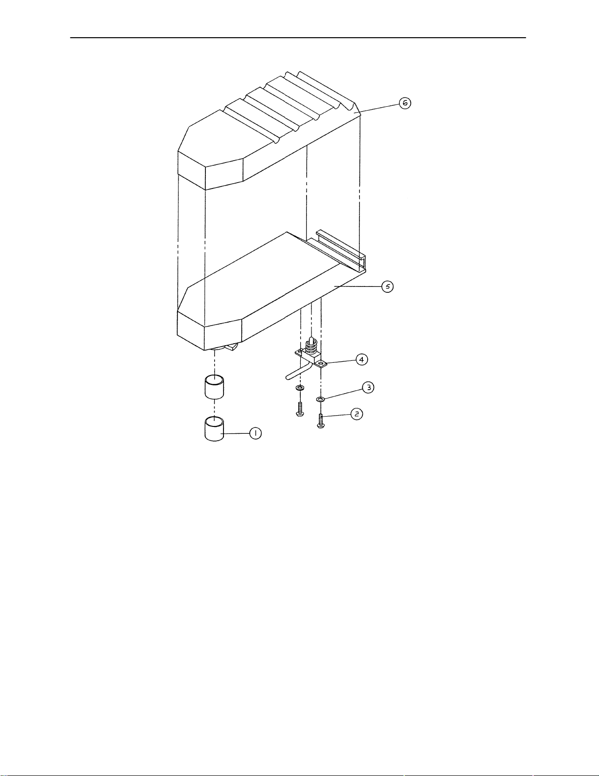
0591–09–00 Foot Pan Assembly
Item Part No. Part Name Qty.
1 0021–04–00 Bushing 2
2 0022–24–00 Truss Head Screw 2
3 0025–07–00 Internal Tooth Lock Washer 2
4 (page 51) Foot Pan Latch Assembly 1
5 0590–57–00 Foot Pan 1
6 0590–58–00 Foot Pan Pad 1
7 0063–02–00 Adhesive Transfer Tape .45 Yd.*
8 0063–03–00 Adhesive Transfer Tape .92 Yd.*
*Items 7 and 8 are not shown. They are used to fasten item 6 to item 5.
50
Page 54
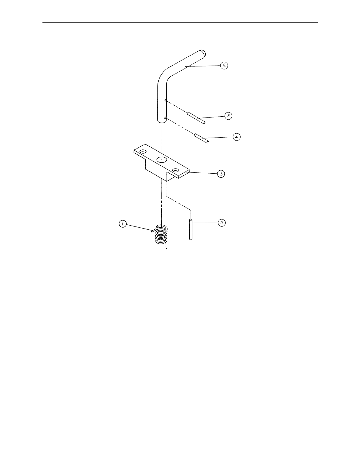
0590–61–00 Foot Pan Latch Assembly
Item Part No. Part Name Qty.
1 0590–65–00 Torsion Spring 1
2 3978–33–00 Roll Pin 2
3 0590–63–00 Foot Pan Latch Base 1
4 0590–64–00 Roll Pin 1
5 0590–62–00 Foot Pan Latch Pin 1
51
Page 55
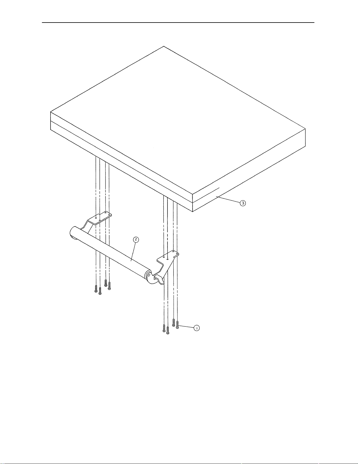
0307–29–00 Foot End Mattress & Push Bar Assembly
Item Part No. Part Name Qty.
1 0690–00–00 Screw 8
2 (page 53) Push Bar Assembly 1
3 0307–30–00 Foot Mattress Assembly 1
52
Page 56
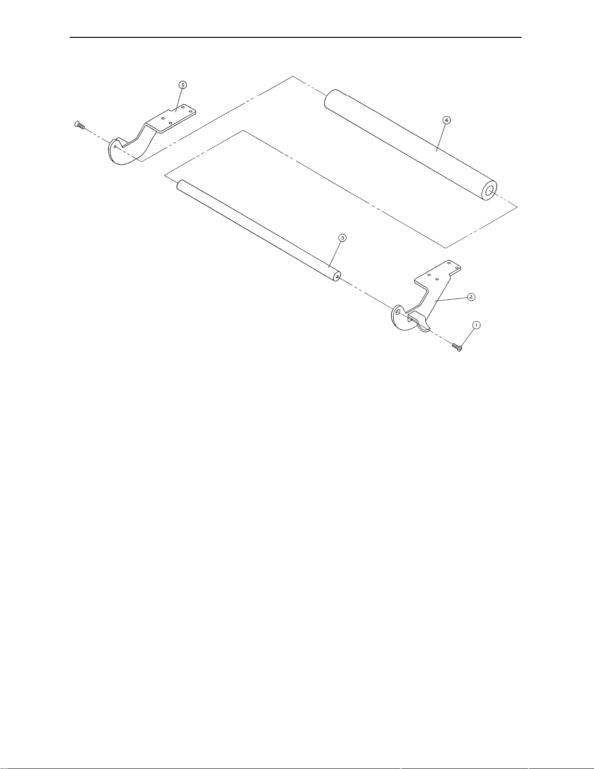
0595–42–00 Push Bar Assembly
Item Part No. Part Name Qty.
1 0022–44–00 Phillips Flat Hd. Screw 2
2 0595–23–00 Push Bar Bracket, Lt. 1
3 0307–38–00 Push Bar 1
4 0589–90–00 Cover Foam 1
5 0595–24–00 Push Bar Bracket, Rt. 1
53
Page 57
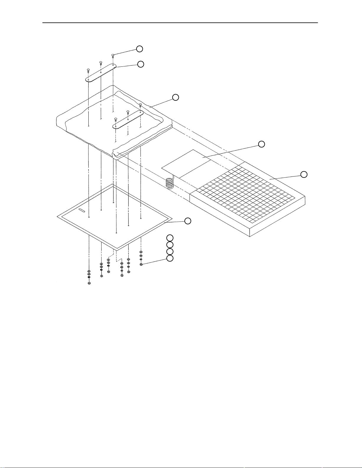
0310–65–00 Head Section Assembly*
9
8
7
6
5
4
3
3
2
1
Item Part No. Part Name Qty.
1 0318–38–00 Acorn Nut 6
2 0025–07–00 Int. Th. Lock Washer 6
3 0025–05–00 Flat Washer 12
4 0310–63–00 Head Panel 1
5 0310–62–00 Head Foam 1
6 0300–24–00 Lumbar Bag 1
7 0310–64–00 Head Cover 1
8 0310–68–00 Retainer Plate 2
9 0318–37–00 Rib Neck Bolt 6
10 0310–66–00 Union Barb 1
*Use part number 0316–10–00 for Head Mattress Replacement Kit.
54
Page 58
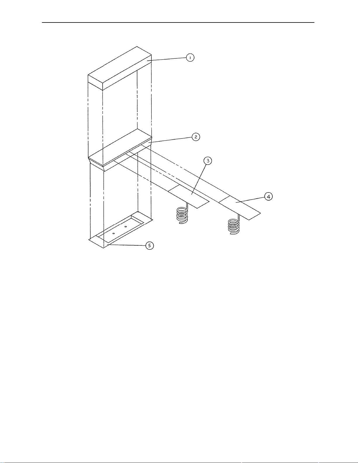
0300–51–00 Seat Mattress Assembly*
Item Part No. Part Name Qty.
1 0300–79–00 Mattress Seat Cover 1
2 0300–49–00 Seat Foam 1
3 0306–53–00 Seat Air Panel, Lt. 1
4 0306–52–00 Seat Air Panel, Rt. 1
5 0302–60–00 Seat Panel 1
6 0605–25–00 Adhesive Tape A/R
*Use part number 0316–11–00 for Seat Panel Mattress Kit
55
Page 59
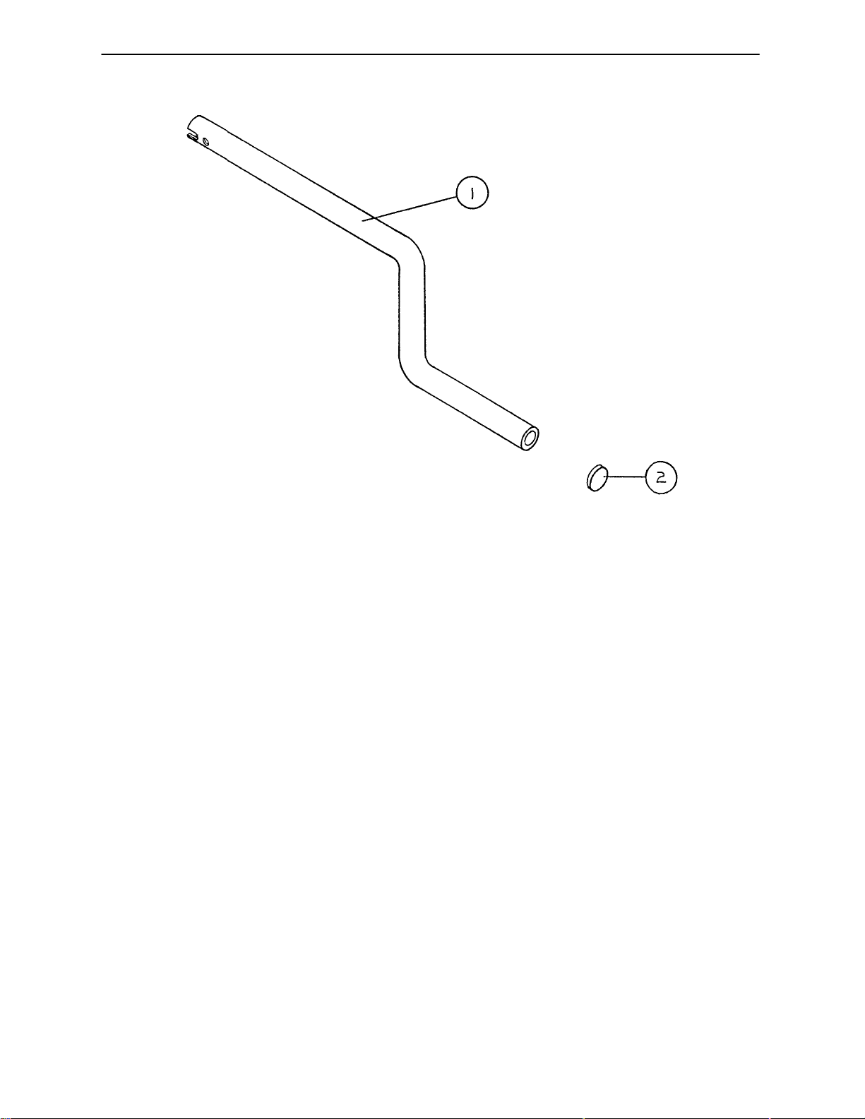
0593–11–00 Hand Crank Assembly
Item Part No. Part Name Qty.
1 0589–43–00 Hand Crank 1
2 0055–01–00 Plug 1
56
Page 60
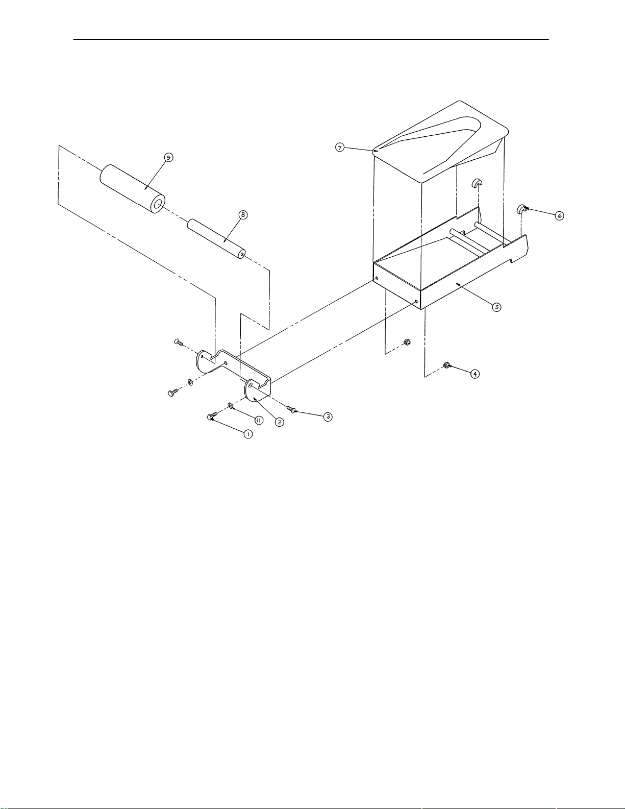
0595–50–00 Foot Rest Assembly
Item Part No. Part Name Qty.
1 3979–37–00 Hex Hd. Cap Screw 2
2 0595–25–00 Foot Rest Handle Bracket 1
3 0022–44–00 Phillips Flat Head Screw 2
4 0024–02–00 Nut 2
5 0590–59–00 Foot Rest 1
6 0594–49–00 Foot Rest Bushing 2
7 0590–60–00 Foot Rest Pad 1
8 0307–40–00 Foot Rest Handle Bar 1
9 0307–43–00 Foam Cover 1
10* 0063–02–00 Adhesive Tape (not shown) .27 Yd.
11 0025–09–00 Lock Washer 2
*Used when installing item 7 to item 5.
57
Page 61

Warranty
Limited Warranty:
Stryker Adel warrants to the original purchaser that its products should be free from defects in material and
workmanship for a period of one (1) year after date of delivery . Stryker Adel ’s obligation under this warranty
is expressly limited to supplying replacement parts and labor for, or replacing, at its option, any product which
is, in the sole discretion of Stryker Adel, found to be defective. Stryker Adel warrants to the original purchaser
that the frame and welds on its beds will be free from structural defects for as long as the original purchaser
owns the bed. If requested by Stryker Adel, products or parts for which a warranty claim is made shall be
returned prepaid to Stryker Adel’s factory. Any improper use or any alteration or repair by others in such manner as in Stryker Adel’s judgement affects the product materially and adversely shall void this warranty. No
employee or representative of Adel is authorized to change this warranty in any way.
This statement constitutes Stryker Adel’s entire warranty with respect to the aforesaid equipment. STRYKER
ADEL MAKES NO OTHER WARRANTY OR REPRESENTATION, EITHER EXPRESSED OR IMPLIED,
EXCEPT AS SET FORTH HEREIN. THERE IS NO WARRANTY OF MERCHANTABILITY AND THERE
ARE NO WARRANTIES OF FITNESS FOR ANY PARTICULAR PURPOSE. IN NO EVENT SHALL STRYKER ADEL BE LIABLE HEREUNDER FOR INCIDENTAL OR CONSEQUENTIAL DAMAGES ARISING
FROM OR IN ANY MANNER RELATED TO SALES OR USE OF ANY SUCH EQUIPMENT.
To Obtain Parts and Service:
Stryker Adel products are supported by a nationwide network of dedicated Stryker Adel Field Service Representatives. These representatives are factory trained, available locally, and carry a substantial spare parts
inventory to minimize repair time. Simply call your local representative, or call Stryker Adel Customer Service
at (800) 327–0770.
Supplemental Warranty Coverage:
Stryker Adel has developed a comprehensive program of extended warranty options designed to keep your
equipment operating at peak performance at the same time it eliminates unexpected costs. We recommend
that these programs be activated before the expiration of the new product warranty to eliminate the potential
of additional equipment upgrade charges. Stryker Adel offers the following Supplemental Warranties:
Extended (Parts and Labor)
S All replacement parts (excluding mattresses and consumable items)
S Labor and travel for all scheduled and unscheduled calls
S Biannual Preventive Maintenance Inspections and repairs
S JCAHO paperwork for preventive maintenance
S Priority Emergency Service
Standard (Labor Only):
S Labor and travel for all scheduled and unscheduled calls
S Biannual Preventive Maintenance Inspections and repairs
S JCAHO paperwork for preventive maintenance
S Priority Emergency Service
Basic (Parts Only):
S All replacement parts (excluding mattresses and consumable items)
S Priority Emergency Service
Please call your local representative, or call (800) 327–0770 for further information
58
Page 62

Warranty
Return Authorization:
Merchandise cannot be returned without approval from the Stryker Adel Customer Service Department. An
authorization number will be provided which must be printed on the returned merchandise. Stryker Adel reserves the right to charge shipping and restocking fees on returned items.
SPECIAL, MODIFIED, OR DISCONTINUED ITEMS NOT SUBJECT TO RETURN.
Damaged Merchandise:
ICC Regulations require that claims for damaged merchandise must be made with the carrier within fifteen
(15) days of receipt of merchandise. DO NOT ACCEPT DAMAGED SHIPMENTS UNLESS SUCH DAMAGE
IS NOTED ON THE DELIVERY RECEIPT AT THE TIME OF RECEIPT. Upon prompt notification, Stryker
Adel will file a freight claim with the appropriate carrier for damages incurred. Claim will be limited in amount
to the actual replacement cost. In the event that this information is not received by Stryker Adel within the
fifteen (15) day period following the delivery of the merchandise, or the damage was not noted on the delivery
receipt at the time of receipt, the customer will be responsible for payment of the original invoice in full.
Claims for any short shipment must be made within thirty (30) days of invoice.
59
Page 63

6300 Sprinkle Road, Kalamazoo, MI 49001–9799 (800) 327–0770
DH 2/94 0309–89–00 REV 1 ECN #4619
 Loading...