

Page 1

IMPORTANT
File in your
maintenance
records
TriaDyne III Proventa Bed
Model 2033
MAINTENANCE MANUAL
Page 2

INTRODUCTION AND SET−UP INFORMATION
Introduction 1−1. . . . . . . . . . . . . . . . . . . . . . . . . . . . . . . . . . . . . . . . . . . . . . . . . . . . . . . . . . . . . . . . . . . . . . . . . . .
Specifications 1−1. . . . . . . . . . . . . . . . . . . . . . . . . . . . . . . . . . . . . . . . . . . . . . . . . . . . . . . . . . . . . . . . . . . . . . . . . .
Warning/Caution/Note Information 1−1. . . . . . . . . . . . . . . . . . . . . . . . . . . . . . . . . . . . . . . . . . . . . . . . . . . . . . . .
Warranty 1−2. . . . . . . . . . . . . . . . . . . . . . . . . . . . . . . . . . . . . . . . . . . . . . . . . . . . . . . . . . . . . . . . . . . . . . . . . . . . . .
Safety Tips and Guidelines 1−3, 1−4. . . . . . . . . . . . . . . . . . . . . . . . . . . . . . . . . . . . . . . . . . . . . . . . . . . . . . . . . .
Set−Up Procedures 1−5. . . . . . . . . . . . . . . . . . . . . . . . . . . . . . . . . . . . . . . . . . . . . . . . . . . . . . . . . . . . . . . . . . . . .
Bed Symbols 1−6 − 1−9. . . . . . . . . . . . . . . . . . . . . . . . . . . . . . . . . . . . . . . . . . . . . . . . . . . . . . . . . . . . . . . . . . . .
PREVENTIVE MAINTENANCE
Cleaning 2−2. . . . . . . . . . . . . . . . . . . . . . . . . . . . . . . . . . . . . . . . . . . . . . . . . . . . . . . . . . . . . . . . . . . . . . . . . . . . . .
Preventive Maintenance Checklist 2−3. . . . . . . . . . . . . . . . . . . . . . . . . . . . . . . . . . . . . . . . . . . . . . . . . . . . . . . .
TROUBLESHOOTING
Troubleshooting Guide 3−2. . . . . . . . . . . . . . . . . . . . . . . . . . . . . . . . . . . . . . . . . . . . . . . . . . . . . . . . . . . . . . . . . .
ELECTRICAL SYSTEM INFORMATION
CPU Board 4−2, 4−3. . . . . . . . . . . . . . . . . . . . . . . . . . . . . . . . . . . . . . . . . . . . . . . . . . . . . . . . . . . . . . . . . . . . . . . .
Power Supply 4−4. . . . . . . . . . . . . . . . . . . . . . . . . . . . . . . . . . . . . . . . . . . . . . . . . . . . . . . . . . . . . . . . . . . . . . . . . .
QUICK REFERENCE REPLACEMENT PARTS LIST
Quick Reference Replacement Parts List 5−1. . . . . . . . . . . . . . . . . . . . . . . . . . . . . . . . . . . . . . . . . . . . . . . . . .
Page 3

BASE MAINTENANCE
Static Discharge Precautions 6−2. . . . . . . . . . . . . . . . . . . . . . . . . . . . . . . . . . . . . . . . . . . . . . . . . . . . . . . . . . . .
Brake Pedal Replacement 6−3. . . . . . . . . . . . . . . . . . . . . . . . . . . . . . . . . . . . . . . . . . . . . . . . . . . . . . . . . . . . . . .
Lift Motor and Capacitor Removal and Replacement 6−4. . . . . . . . . . . . . . . . . . . . . . . . . . . . . . . . . . . . . . . .
Lift Housing Removal and Replacement 6−5, 6−6. . . . . . . . . . . . . . . . . . . . . . . . . . . . . . . . . . . . . . . . . . . . . . .
Lift Potentiometer Replacement and Adjustment 6−7, 6−8. . . . . . . . . . . . . . . . . . . . . . . . . . . . . . . . . . . . . . . .
Lift Potentiometer “Burn−In” Procedure 6−8. . . . . . . . . . . . . . . . . . . . . . . . . . . . . . . . . . . . . . . . . . . . . . . . . . . .
Lift Motor Coupler Replacement 6−9. . . . . . . . . . . . . . . . . . . . . . . . . . . . . . . . . . . . . . . . . . . . . . . . . . . . . . . . . .
Power and Sensor Coil Cord Replacement 6−10, 6−11. . . . . . . . . . . . . . . . . . . . . . . . . . . . . . . . . . . . . . . . . .
LITTER MAINTENANCE
Scale System Diagnostics and Calibration 7−2, 7−3. . . . . . . . . . . . . . . . . . . . . . . . . . . . . . . . . . . . . . . . . . . . .
Load Cell Replacement 7−4. . . . . . . . . . . . . . . . . . . . . . . . . . . . . . . . . . . . . . . . . . . . . . . . . . . . . . . . . . . . . . . . .
Head Motor Removal and Replacement 7−4. . . . . . . . . . . . . . . . . . . . . . . . . . . . . . . . . . . . . . . . . . . . . . . . . . .
Knee Motor Removal and Replacement 7−5. . . . . . . . . . . . . . . . . . . . . . . . . . . . . . . . . . . . . . . . . . . . . . . . . . .
Power Supply Removal and Replacement 7−6. . . . . . . . . . . . . . . . . . . . . . . . . . . . . . . . . . . . . . . . . . . . . . . . .
CPU Board Removal and Replacement 7−6. . . . . . . . . . . . . . . . . . . . . . . . . . . . . . . . . . . . . . . . . . . . . . . . . . .
Fowler Potentiometer Replacement 7−7. . . . . . . . . . . . . . . . . . . . . . . . . . . . . . . . . . . . . . . . . . . . . . . . . . . . . . .
Fowler and Lift Potentiometer “Burn−In” Procedure 7−8. . . . . . . . . . . . . . . . . . . . . . . . . . . . . . . . . . . . . . . . .
SIDERAIL MAINTENANCE
Head and Foot End Siderail Cover Removal 8−2. . . . . . . . . . . . . . . . . . . . . . . . . . . . . . . . . . . . . . . . . . . . . . .
Head and Foot Molded Siderail Replacement 8−3. . . . . . . . . . . . . . . . . . . . . . . . . . . . . . . . . . . . . . . . . . . . . .
Head End Siderail Cable Replacement 8−4, 8−5. . . . . . . . . . . . . . . . . . . . . . . . . . . . . . . . . . . . . . . . . . . . . . . .
FOOT BOARD MAINTENANCE
Foot Board Hinge Removal 9−2. . . . . . . . . . . . . . . . . . . . . . . . . . . . . . . . . . . . . . . . . . . . . . . . . . . . . . . . . . . . . .
Foot Board Module Replacement 9−3. . . . . . . . . . . . . . . . . . . . . . . . . . . . . . . . . . . . . . . . . . . . . . . . . . . . . . . . .
Foot Board Interface Plug Replacement 9−4. . . . . . . . . . . . . . . . . . . . . . . . . . . . . . . . . . . . . . . . . . . . . . . . . . .
Page 4

ASSEMBLY DRAWINGS AND PARTS LISTS
Base Assembly 10−3 − 10−9. . . . . . . . . . . . . . . . . . . . . . . . . . . . . . . . . . . . . . . . . . . . . . . . . . . . . . . . . . . . . . . .
Lift Assembly 10−10 − 10−13. . . . . . . . . . . . . . . . . . . . . . . . . . . . . . . . . . . . . . . . . . . . . . . . . . . . . . . . . . . . . . . .
Isolation Plate Assembly 10−14. . . . . . . . . . . . . . . . . . . . . . . . . . . . . . . . . . . . . . . . . . . . . . . . . . . . . . . . . . . . . .
Brake Shaft Assembly 10−15. . . . . . . . . . . . . . . . . . . . . . . . . . . . . . . . . . . . . . . . . . . . . . . . . . . . . . . . . . . . . . . .
Brake Crank Assembly 10−16. . . . . . . . . . . . . . . . . . . . . . . . . . . . . . . . . . . . . . . . . . . . . . . . . . . . . . . . . . . . . . . .
Brake Bar Assembly 10−17. . . . . . . . . . . . . . . . . . . . . . . . . . . . . . . . . . . . . . . . . . . . . . . . . . . . . . . . . . . . . . . . . .
8” Caster Assembly 10−18. . . . . . . . . . . . . . . . . . . . . . . . . . . . . . . . . . . . . . . . . . . . . . . . . . . . . . . . . . . . . . . . . .
8” Steer Caster Assembly 10−19. . . . . . . . . . . . . . . . . . . . . . . . . . . . . . . . . . . . . . . . . . . . . . . . . . . . . . . . . . . . .
8” Wheel Assembly 10−20. . . . . . . . . . . . . . . . . . . . . . . . . . . . . . . . . . . . . . . . . . . . . . . . . . . . . . . . . . . . . . . . . . .
Bottom Cover Assembly 10−21. . . . . . . . . . . . . . . . . . . . . . . . . . . . . . . . . . . . . . . . . . . . . . . . . . . . . . . . . . . . . .
Litter Assembly 10−22 − 10−34. . . . . . . . . . . . . . . . . . . . . . . . . . . . . . . . . . . . . . . . . . . . . . . . . . . . . . . . . . . . . .
Actuator Box Cover Assembly 10−35. . . . . . . . . . . . . . . . . . . . . . . . . . . . . . . . . . . . . . . . . . . . . . . . . . . . . . . . .
Fowler Brake Kit Assembly 10−36. . . . . . . . . . . . . . . . . . . . . . . . . . . . . . . . . . . . . . . . . . . . . . . . . . . . . . . . . . . .
Head End Siderail Assembly 10−37 − 10−43. . . . . . . . . . . . . . . . . . . . . . . . . . . . . . . . . . . . . . . . . . . . . . . . . . .
Siderail Release Lever Assembly 10−44, 10−45. . . . . . . . . . . . . . . . . . . . . . . . . . . . . . . . . . . . . . . . . . . . . . . .
Siderail Latch Assembly 10−46, 10−47. . . . . . . . . . . . . . . . . . . . . . . . . . . . . . . . . . . . . . . . . . . . . . . . . . . . . . . .
Siderail Bypass Detent Clip Assembly 10−48. . . . . . . . . . . . . . . . . . . . . . . . . . . . . . . . . . . . . . . . . . . . . . . . . . .
Head End Siderail Outer Panel Assembly 10−49. . . . . . . . . . . . . . . . . . . . . . . . . . . . . . . . . . . . . . . . . . . . . . . .
Head End Siderail Inner Panel Assembly 10−50. . . . . . . . . . . . . . . . . . . . . . . . . . . . . . . . . . . . . . . . . . . . . . . .
Foot End Siderail Assembly 10−51 − 10−55. . . . . . . . . . . . . . . . . . . . . . . . . . . . . . . . . . . . . . . . . . . . . . . . . . .
Head Board Assembly 10−56. . . . . . . . . . . . . . . . . . . . . . . . . . . . . . . . . . . . . . . . . . . . . . . . . . . . . . . . . . . . . . . .
Foot Board Assembly 10−57. . . . . . . . . . . . . . . . . . . . . . . . . . . . . . . . . . . . . . . . . . . . . . . . . . . . . . . . . . . . . . . . .
Foot Board Bed Exit Module Assembly 10−58. . . . . . . . . . . . . . . . . . . . . . . . . . . . . . . . . . . . . . . . . . . . . . . . . .
KCI Foot Board Module Assembly 10−59. . . . . . . . . . . . . . . . . . . . . . . . . . . . . . . . . . . . . . . . . . . . . . . . . . . . . .
Foot Board Main Module Assembly 10−60. . . . . . . . . . . . . . . . . . . . . . . . . . . . . . . . . . . . . . . . . . . . . . . . . . . . .
Foot Board Scale Module Assembly 10−61. . . . . . . . . . . . . . . . . . . . . . . . . . . . . . . . . . . . . . . . . . . . . . . . . . . .
Page 5

ASSEMBLY DRAWINGS AND PARTS LISTS (CONTINUED)
2−Stage I.V. Mounting Assembly, Head End 10−62. . . . . . . . . . . . . . . . . . . . . . . . . . . . . . . . . . . . . . . . . . . . .
2−Stage I.V. Pole Assembly 10−63. . . . . . . . . . . . . . . . . . . . . . . . . . . . . . . . . . . . . . . . . . . . . . . . . . . . . . . . . . .
I.V. Pole Latch Assembly 10−64. . . . . . . . . . . . . . . . . . . . . . . . . . . . . . . . . . . . . . . . . . . . . . . . . . . . . . . . . . . . . .
Defibrillator Tray Assembly 10−65. . . . . . . . . . . . . . . . . . . . . . . . . . . . . . . . . . . . . . . . . . . . . . . . . . . . . . . . . . . .
Page 6
INTRODUCTION
This manual is designed to assist you with the operation of the Model 2033 Critical Care Bed. Read it thoroughly before using the equipment.
SPECIFICATIONS
Maximum Weight Capacity 300 pounds (136 kilograms)
Weigh System Capacity (optional equipment) patients weighing up to 500 pounds or
patients weighing up to 227 kilograms
Weigh System Accuracy (optional equipment) 2% of total patient weight at zero degrees of T rend
Overall Bed Length/Width L−91” /W−42.5” or L−231 cm /W−108 cm
Minimum/Maximum Bed Height (Standard)
Minimum/Maximum Bed Height (Enhanced)
Fluoro Access 17.5”
Knee Gatch Angle 0_ to 30_
Back Angle 0_ to 90_
Trendelenburg/Reverse Trendelenburg −14_ to +14_
Electrical Requirements 115 VAC, 60 Hz, 7.0 Amps
Noise Level > 65 Decibels
20.25” to 34.5” − 51.5 cm. to 88 cm.
21.9” to 36.5” − 56 cm. to 93 cm.
Stryker reserves the right to change specifications without notice.
WARNING / CAUTION / NOTE DEFINITION
The words WARNING, CAUTION and NOTE carry special meanings and should be carefully reviewed.
WARNING
The personal safety of the patient or user may be involved. Disregarding this information could result in injury
to the patient or user.
CAUTION
These instructions point out special procedures or precautions that must be followed to avoid damaging the
equipment.
NOTE
This provides special information to make maintenance easier or important instructions clearer.
page 1−1
Page 7

Warranty
Limited Warranty:
Stryker Medical Division, a division of Stryker Corporation, warrants to the original purchaser that its products
should be free from defects in material and workmanship for a period of one (1) year after date of delivery.
Stryker’s obligation under this warranty is expressly limited to supplying replacement parts and labor for, or
replacing, at its option, any product which is, in the sole discretion of Stryker, found to be defective. Stryker
warrants to the original purchaser that the frame and welds on its beds will be free from structural defects
for as long as the original purchaser owns the bed. If requested by Stryker , products or parts for which a
warranty claim is made shall be returned prepaid to Stryker’s factory. Any improper use or any alteration or
repair by others in such manner as in Stryker’s judgement affects the product materially and adversely shall
void this warranty. Any repair of Stryker products using parts not provided or authorized by Stryker shall void
this warranty. No employee or representative of Stryker is authorized to change this warranty in any way.
Stryker Medical beds are designed for a 10 year expected life under normal use conditions and appropriate
periodic maintenance as described in the maintenance manual for each device.
This statement constitutes Stryker ’s entire warranty with respect to the aforesaid equipment. STRYKER
MAKES NO OTHER WARRANTY OR REPRESENTATION, EITHER EXPRESSED OR IMPLIED, EXCEPT
AS SET FOR TH HEREIN. THERE IS NO W ARRANTY OF MERCHANTABILITY AND THERE ARE NO
WARRANTIES OF FITNESS FOR ANY PARTICULAR PURPOSE. IN NO EVENT SHALL STRYKER BE
LIABLE HEREUNDER FOR INCIDENTAL OR CONSEQUENTIAL DAMAGES ARISING FROM OR IN ANY
MANNER RELATED TO SALES OR USE OF ANY SUCH EQUIPMENT .
Return Authorization:
Merchandise cannot be returned without approval from the Stryker Customer Service Department. An authorization number will be provided which must be printed on the returned merchandise. Stryker reserves the
right to charge shipping and restocking fees on returned items.
SPECIAL, MODIFIED, OR DISCONTINUED ITEMS NOT SUBJECT T O RETURN.
Damaged Merchandise:
ICC Regulations require that claims for damaged merchandise must be made with the carrier within fifteen
(15) days of receipt of merchandise. DO NOT ACCEPT DAMAGED SHIPMENTS UNLESS SUCH DAMAGE
IS NOTED ON THE DELIVERY RECEIPT AT THE TIME OF RECEIPT. Upon prompt notification, Stryker
will file a freight claim with the appropriate carrier for damages incurred. Claim will be limited in amount to
the actual replacement cost. In the event that this information is not received by Stryker within the fifteen
(15) day period following the delivery of the merchandise, or the damage was not noted on the delivery receipt
at the time of receipt, the customer will be responsible for payment of the original invoice in full.
Claims for any short shipment must be made within thirty (30) days of invoice.
International Warranty Clause:
This warranty reflects U.S. domestic policy. Warranty outside the U.S. may vary by country. Please contact
your local Stryker Medical representative for additional information.
page 1−2
Page 8

Safety Tips and Guidelines
Before operating the 2030, it is important to read and understand all information in this manual. Carefully read
and strictly follow the safety guidelines listed on this page. It is important that all users have been trained
and educated on the inherent hazards associated with the usage of electric beds.
WARNING
The 2030 is not intended for use with patients less than two years of age.
S
S Powered bed mechanisms can cause serious injury. Operate bed only when all persons are clear of the
mechanisms.
S To help reduce the number and severity of falls by patients, always leave the bed in the lowest position
when the patient is unattended.
S Leave the siderails fully up and locked when the patient is unattended. When raising the siderails, listen
for the ”click” that indicates the siderail has locked in the up position. Pull firmly on the siderail to ensure
it is locked into position.
Siderails are not intended to be a patient restraint device. It is the responsibility of the attending medical
personnel to determine the degree of restraint necessary to ensure a patient will remain safely in bed.
S Always apply the caster brakes when a patient is getting on or off the bed. Always keep the caster brakes
applied when a patient is on the bed (except during transport). Serious injury could result if the bed moves
while a patient is getting in or out of bed. After the brake pedal is applied, push on the bed to ensure the
brakes are locked. When moving the bed, toggle the steer pedal to put the bed in the steer mode. This
locks the swivel motion of the right foot end caster and makes the bed easier to move.
S When large spills occur in the area of the circuit boards, 110 volt cables and motors, immediately unplug
the bed power cord from the wall socket. Remove the patient from the bed and clean up the fluid. Have
maintenance completely check the bed. Fluids can affect the operational capabilities of any electrical
product. DO NOT put the bed back into service until it is completely dry and has been thoroughly tested
for safe operation.
S Do not steam clean or hose off the bed. Do not immerse any part of the bed. The internal electric parts
may be damaged by exposure to water. Hand wash all surfaces of the bed with warm water and mild
detergent. Dry thoroughly. Quaternary Germicidal Disinfectants, used as directed, and/or Chlorine
Bleach products, typically 5.25% Sodium Hypochlorite in dilutions ranging between 1 part bleach to 100
parts water, and 2 parts bleach to 100 parts water are not considered mild detergents. THESE PROD-
UCTS ARE CORROSIVE IN NATURE AND MAY CAUSE DAMAGE TO YOUR BED IF USED IMPROPERLY. If these types of products are used to clean Stryker patient care equipment, measures must be
taken to insure the beds are wiped with clean water and thoroughly dried following cleaning. Failure to
properly rinse and dry the beds will leave a corrosive residue on the surface of the bed, possibly causing
premature corrosion of critical components. Failure to follow the above directions when using these types
of cleaners may void this product’s warranty.
Clean Velcro AFTER EACH USE. Saturate Velcro with disinfectant and allow disinfectant to evaporate.
(Appropriate disinfectant for nylon Velcro should be determined by the hospital.)
S Preventative maintenance should be performed at a minimum of annually to ensure all bed features are
functioning properly. Close attention should be given to safety features including, but not limited to:
safety side latching mechanisms, frayed electrical cords and components, all electrical controls return
to off or neutral position when released, caster braking systems, no controls or cabling entangled in bed
mechanisms, leakage current 100 MA maximum, scale and bed exit systems calibrated properly.
S Always unplug bed during service or cleaning. When working under the bed with the bed in the high posi-
tion, always place blocks under the litter frame and set the brakes to prevent injury in case the Bed Down
switch is accidently pressed.
S Explosion Hazard − do not use bed in the presence of flammable anesthetics.
S Because individual beds may have different options, foot boards should not be moved from one bed to
another. Mixing foot boards could result in unpredictable bed operation.
page 1−3
Page 9
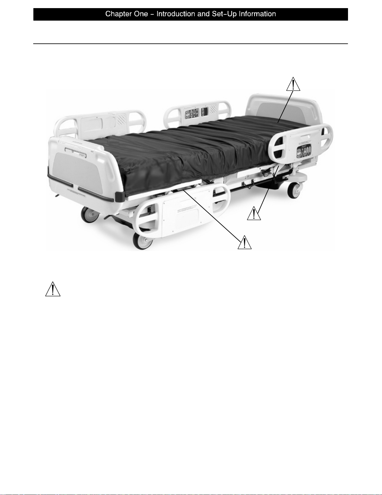
Safety Tips and Guidelines
WARNING
Potential pinch points
page 1−4
Page 10

Set−Up Procedures
It is important that the bed is working properly before it is put into service. The following list will help ensure
that each part of the bed is tested.
S Plug the bed into a properly grounded, hospital grade wall receptacle and ensure the ”Power” LED light
at the foot end of the bed comes on.
WARNING
The 2033 is equipped with a hospital grade plug for protection against shock hazard. It must be plugged directly into a properly grounded three−prong receptacle. Grounding reliability can be achieved only when a
hospital grade receptacle is used.
S Ensure the siderails raise, lower and store smoothly and lock in the up and intermediate positions.
S Ensure that all four casters lock when the brake pedal is engaged
NOTE
Ensure that the ”Brake Not Set” LEDs located on the outside of the head end siderails and on the foot board
control panel come on when the brakes are disengaged.
S Run through each function on the foot board control panel to ensure that each function is working properly.
S Run through each function on both head end siderails to ensure that each is working properly.
If any problems are found during bed set−up, contact Stryker Customer Service at 800−327−0770.
Damaged Merchandise
ICC Regulations require that claims for damaged merchandise must be made with the carrier within fifteen
(15) days of receipt of merchandise. DO NOT ACCEPT DAMAGED SHIPMENTS UNLESS SUCH DAMAGE
IS NOTED ON THE DELIVERY RECEIPT AT THE TIME OF RECEIPT. Stryker Customer Service must be
notified immediately. Stryker will aid the customer in filing a freight claim with the appropriate carrier for damages incurred. Claim will be limited in amount to the actual replacement cost. In the event that this information
is not received by Stryker within the fifteen (15) day period following the delivery of the merchandise, or the
damage was not noted on the delivery receipt at the time of receipt, the customer will be responsible for payment of the original invoice in full.
Claims for any short shipment must be made within thirty (30) days of invoice.
page 1−5
Page 11
Bed Symbols
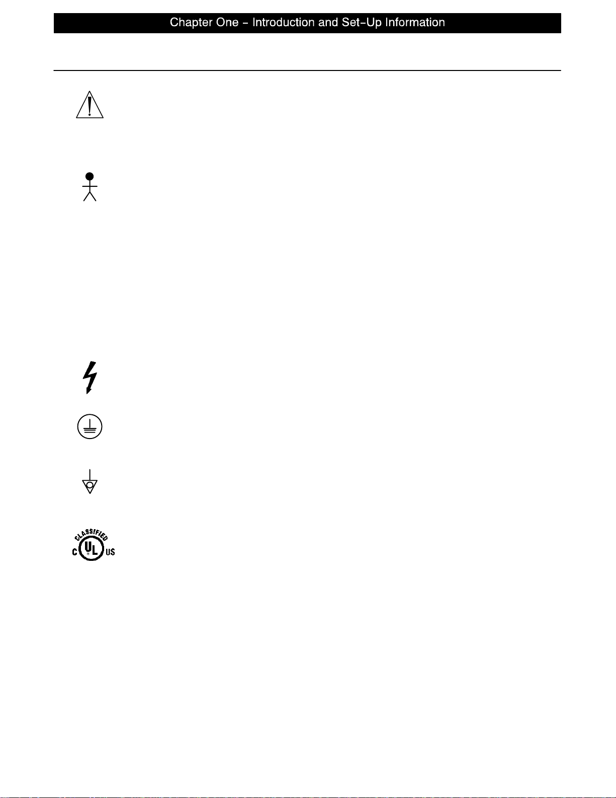
Warning, Refer to Service/Maintenance Manual
~
Alternating Current
Type B Equipment: equipment providing a particular degree of protection against electric shock, particularly regarding allowable leakage current and reliability of the protective earth connection.
Class 1 Equipment: equipment in which protection against electric shock does not rely
on BASIC INSULATION only, but which includes an additional safety precaution in that
means are provided for the connection of the EQUIPMENT to the protective earth conductor in the fixed wiring of the installation in such a way that ACCESSIBLE METAL
PARTS cannot become live in the event of a failure of the BASIC INSULA TION.
Mode of Operation: Continuous
IPX4: Protection from liquid splash
Dangerous Voltage Symbol
Protective Earth Terminal
page 1−6
Potential Equalization Symbol
Medical Equipment Classified by Underwriters Laboratories Inc. with Respect to Electric Shock, Fire, Mechanical and Other Specified Hazards Only in Accordance with UL
2601−1 and CAN/CSA C22.2 No. 601.1
Page 12
Bed Symbols
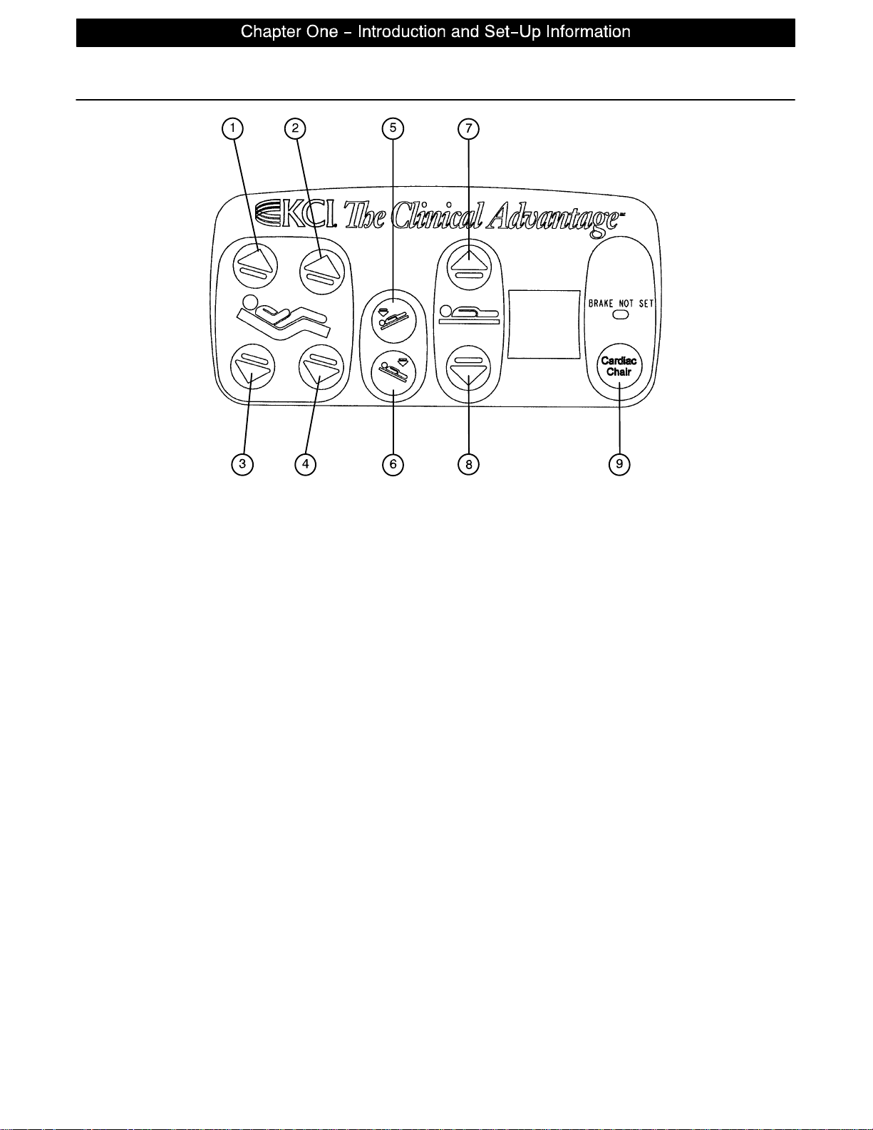
1. Press to raise back section.
2. Press to raise knee section.
3. Press to lower back section.
4. Press to lower knee section.
5. Press to lower the head end of the bed (Trendelenburg).
6. Press to lower the foot end of the bed (Reverse Trendelenburg).
7. Press to raise the litter.
8. Press to lower the litter.
9. Press to activate emergency Cardiac Chair positioning.
page 1−7
Page 13
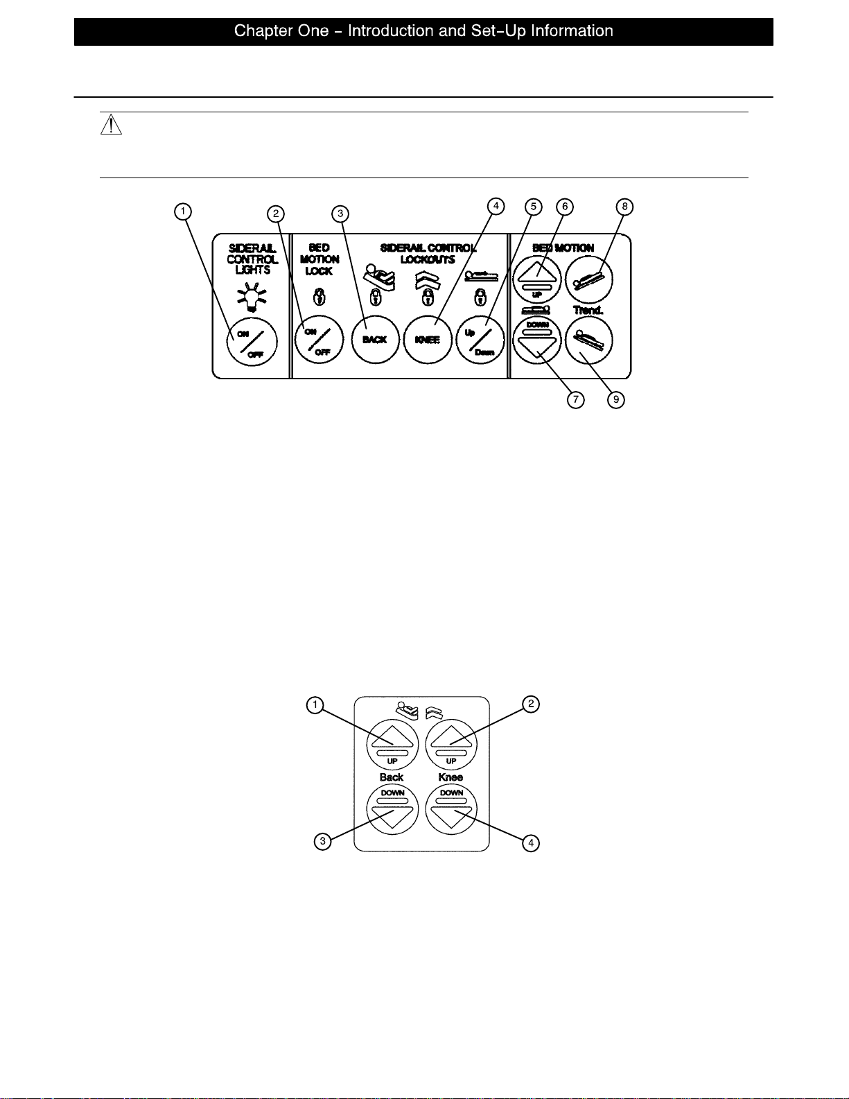
Bed Symbols
WARNING
Because individual beds may have different options, foot boards should not be moved from one bed to another. Mixing foot boards could result in unpredictable bed operation.
1. Press repeatedly for low, medium and high settings for the siderail control lights. Continue to press this
switch to turn off the siderail control lights and the nurse call indicator light.
2. Press to lock out all bed motion controls on the siderails. Press again to unlock.
3. Press to lock out Back motion control on the siderails. Press again to unlock.
4. Press to lock out Knee motion control on the siderails. Press again to unlock.
5. Press to lock out bed up/down motion controls on the siderails. Press again to unlock.
6. Press to raise bed.
7. Press to lower bed.
8. Press to lower head end of bed (Trendelenburg).
9. Press to lower foot end of bed (Reverse Trendelenburg).
1. Press to raise back section.
2. Press to raise knee section.
3. Press to lower back section.
4. Press to lower knee section.
page 1−8
Page 14
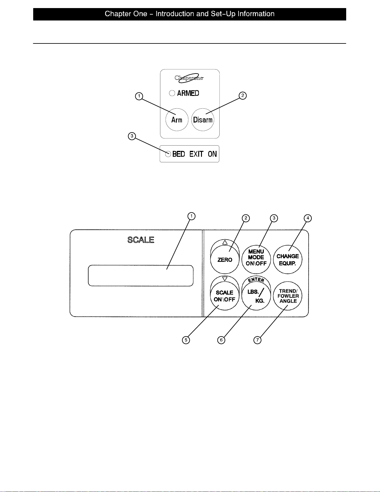
Bed Symbols
1. Push to activate Bed Exit function.
2. Push to deactivate Bed Exit function.
3. “BED EXIT ON” LED − will light when the BED EXIT function is armed.
1. LCD − displays patient weight. Trendelenburg angle is displayed when the scale is not active.
2. Press to zero bed. Also press to scroll while Menu Mode is active.
3. Press to enter and exit the Menu Mode.
4. Press when adding or removing equipment to the bed.
5. Press to turn weigh system on and off. Also press to scroll while Menu Mode is active.
6. Press to change weight from pounds to kilograms or back. Also press while using the Menu Mode.
7. Press to display the Trendelenburg or Fowler angle of the bed.
page 1−9
Page 15

Notes
page 1−10
Page 16

GENERAL INFORMATION
This section contains cleaning instructions and a checklist to assist with the routine preventive maintenance
and cleaning of your equipment.
PREVENTIVE MAINTENANCE CONTENTS
Cleaning 2−2. . . . . . . . . . . . . . . . . . . . . . . . . . . . . . . . . . . . . . . . . . . . . . . . . . . . . . . . . . . . . . . . . . . . . . . . . . . . . .
Preventive Maintenance Checklist 2−3. . . . . . . . . . . . . . . . . . . . . . . . . . . . . . . . . . . . . . . . . . . . . . . . . . . . . . . .
page 2−1
Page 17
Cleaning
Hand wash all surfaces of the bed with warm water and mild detergent. Dry thoroughly. DO NOT STEAM
CLEAN, PRESSURE WASH, HOSE OFF OR ULTRASONICALLY CLEAN. Using these methods of cleaning
is not recommended and may void this product’s warranty.
Clean Velcro AFTER EACH USE. Saturate Velcro with disinfectant and allow disinfectant to evaporate. (Ap-
propriate disinfectant for nylon Velcro should be determined by the hospital.)
In general, when used in those concentrations recommended by the manufacturer, either phenolic type or
quaternary type disinfectants can be used with Staph−Chek fabrics. Iodophor type disinfectants are not recommended for use on Staph−Chek fabrics because staining may result. The following products have been
tested by the Herculite Laboratory and have been found not to have a harmful effect on Staph−Chek fabrics
WHEN USED IN ACCORDANCE WITH MANUFACTURERS RECOMMENDED DILUTION.*
TRADE NAME
A33 Quaternary Airwick (Professional Products Division) 2 ounces/gallon
A33 (dry) Quaternary Airwick (Professional Products Division) 1/2 ounce/gallon
Beaucoup Phenolic Huntington Laboratories 1 ounce/gallon
Blue Chip Quaternary S.C. Johnson 2 ounces/gallon
Elimstaph Quaternary Walter G. Legge 1 ounce/gallon
Franklin
Phenomysan
F2500
Franklin Sentinel Quaternary Purex Corporation 2 ounces/gallon
Galahad Phenolic Puritan Churchill Chemical Company 1 ounce/gallon
Hi−To r Quaternary Huntington Laboratories 1/2 ounce/gallon
LPH Phenolic Vestal Laboratories 1/2 ounce/gallon
Matar Phenolic Huntington Laboratories 1/2 ounce/gallon
Omega Quaternary Airwick (Professional Products Division) 1/2 ounce/gallon
Quanto Quaternary Huntington Laboratories 1 ounce/gallon
Sanikleen Quaternary West Chemical Products 2 ounces/ gallon
Sanimaster II Quaternary Service Master 1 ounce/gallon
Vesphene Phenolic Vestal Laboratories 1 1/4 ounce/ gallon
DISINFECTANT
Phenolic Purex Corporation 1 1/4 ounce/gallon
TYPE
MANUFACTURER
*MANUFACTURER’S
RECOMMENDED
DILUTION
Quaternary Germicidal Disinfectants, used as directed, and/or Chlorine Bleach products, typically 5.25% Sodium Hypochlorite in dilutions ranging between 1 part bleach to 100 parts water, and 2 parts bleach to 100
parts water are not considered mild detergents. These products are corrosive in nature and may cause damage to your bed if used improperly. If these types of products are used to clean Stryker patient handling equipment, measures must be taken to insure the beds are rinsed with clean water and thoroughly dried following
cleaning. Failure to properly rinse and dry the beds will leave a corrosive residue on the surface of the bed,
possibly causing premature corrosion of critical components. Failure to follow the above directions when using these types of cleaners may void this product ’s warranty.
REMOVAL OF IODINE COMPOUNDS
This solution may be used to remove iodine stains from mattress cover and foam footrest pad surfaces.
1. Use a solution of 1−2 tablespoons Sodium Thiosulfate in a pint of warm water to clean the stained area.
Clean as soon as possible after staining occurs. If stains are not immediately removed, allow solution to
soak or stand on the surface.
2. Rinse surfaces which have been exposed to the solution in clear water before returning bed to service.
page 2−2
Page 18

Preventive Maintenance Checklist
All fasteners secure
Engage brake pedal and push on the bed to ensure all casters lock securely
Optional locking steer caster engages and disengages properly
Siderails move, latch and stow properly
All functions on siderails working properly (including LED’s)
Manual CPR release working properly
Foot prop intact and working properly
I.V. pole working properly
Optional Foley bag hooks intact
Optional chart rack intact and working properly
Optional CPR board not cracked or damaged and stores properly
No cracks or splits in head and foot boards
All functions on footboard working properly (including LED’s)
No rips or cracks in mattress cover
Scale and Bed Exit system calibrated properly
Power cord not frayed
No cables worn or pinched
All electrical connections tight
All grounds secure to the frame
Ground impedence not more than 100 milliohms
Current leakage not more than 100 microamps
Fowler functioning properly
Bed Serial No.
Completed By:_________________________________ Date:_____________
NOTE
Preventative maintenance should be performed at a minimum of annually. A preventative maintenance program should be established for all Stryker Medical equipment. Preventative maintenance may need to be
performed more frequently based on the usage level of the product.
page 2−3
Page 19

Notes
page 2−4
Page 20

GENERAL INFORMATION
This section contains troubleshooting charts to assist with the diagnosis of a problem with your equipment.
In the text, the words “right” and “left” refer to the right and left sides of a patient lying face up on the bed.
TROUBLESHOOTING CONTENTS
Troubleshooting Guide 3−2. . . . . . . . . . . . . . . . . . . . . . . . . . . . . . . . . . . . . . . . . . . . . . . . . . . . . . . . . . . . . . . . . .
page 3−1
Page 21

Troubleshooting Guide
DEFINITIONS:
DMM = Digital Multi−Meter
PCB = Printed Circuit Board
CPU = Central Processing Unit
NOTE
See page 4−2 through page 4−4 for an outline of bed PCB’s and voltage test points.
PROBLEM/FAILURE
No power to bed A. Unplug bed power cord and check continuity of F1 and F2
with DMM.
B. Check for 120 VAC power at J1 on the power supply, Pin 1
and 2.
C. Check for DC voltages on J2 (Pins 1,2,3 & 6) on power
supply. See page page 4−4 for power supply voltage test
points.
D. If no voltage at J2, unplug connector HDR2 on the CPU
board and recheck for DC voltages at J2 on the power supply.
E. If still no voltage, unplug all cables from the CPU board and
recheck voltages on the CPU board.
No bed down motion. A. Enter diagnostics, (see page page 7−2) and press bed
down. If motion is present, re−burn lift potentiometer limits.
B. Verify HDR3 on the CPU board has a shunt on the two pins
closest to the patient right side of the bed.
C. Check for 5VDC on R145 and R149 positive lead, CPU
ground test point negative lead while pressing the bed down
button.
D. Check for 120 VAC power on HDR33 and HDR34, Pin 1
white and Pin 3 black, of the CPU board.
No bed up motion. A. Enter diagnostics, (see page page 7−2) and press bed
down. If motion is present, re−burn lift potentiometer limits.
B. Verify cable connection on R143 and R147 positive lead,
CPU ground test point negative lead while pushing the bed up
button.
C. Check 120 VAC power on HDR33 and HDR34, Pin 1 white
and Pin 6 red, of the CPU board.
RECOMMENDED ACTION
No Gatch down motion. A. Check for 5VDC on R141 positive lead, CPU ground test
point negative lead while pushing the Gatch down button.
B. Check for 120 VAC power on HDR30 Pin 1 white and Pin 3
black of the CPU board while pushing the Gatch down button.
No Gatch up motion. A. Check for 5VDC on R137 positive lead, CPU ground test
point negative lead while pushing the Gatch up button.
B. Check for 120 VAC on HDR30, Pin 1 white and Pin 2 red of
the CPU board while pushing the Gatch up button.
No Fowler up/or uneven motion. A. Check for 5VDC on R135 positive lead, CPU ground test
point negative lead while pushing the Fowler up button.
B. Check for 120 VAC on HDR29, Pin 1 white and Pin 2 black
of the power supply while pushing the Fowler up button.
C. Refer to Fowler Mechanism Customer Guide
(2030-009-028).
No Fowler down/or uneven motion. A. Check for 5VDC on R139 positive lead, CPU ground test
point negative lead while pushing the Fowler down button.
B. Check for 120 VAC power on HDR29 Pin 1 white and Pin 3
red of the CPU board while pushing the Fowler down button.
C. Refer to Fowler Mechanism Customer Guide
(2030-009-028).
page 3−2
Page 22

GENERAL INFORMATION
This section contains circuit board layouts and other information on the electrical system of the bed.
ELECTRICAL SYSTEM INFORMATION CONTENTS
CPU Board 4−2, 4−3. . . . . . . . . . . . . . . . . . . . . . . . . . . . . . . . . . . . . . . . . . . . . . . . . . . . . . . . . . . . . . . . . . . . . . . .
Power Supply 4−4. . . . . . . . . . . . . . . . . . . . . . . . . . . . . . . . . . . . . . . . . . . . . . . . . . . . . . . . . . . . . . . . . . . . . . . . . .
page 4−1
Page 23
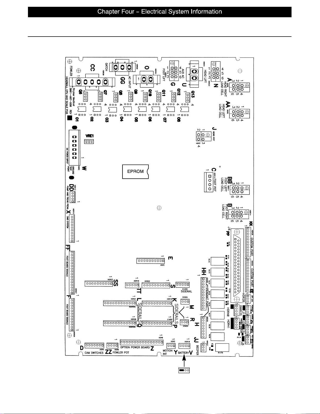
CPU − 2033−700−002
CPU Board
page 4−2
59−137
Shunt for
No Nurse Call
Page 24
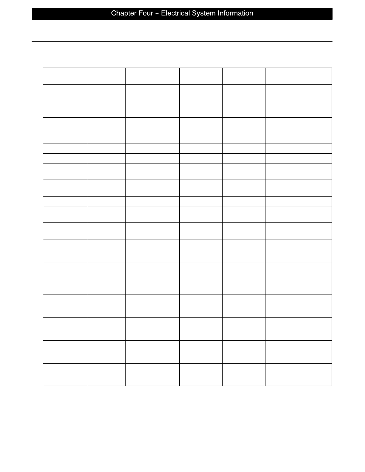
CPU − 2033−700−002
CPU Board (Continued)
CONNECTOR
LOCATION
HDR 2 W +12 VDC Pin 1 Pin 4 or 5 Relays & Siderails
HDR 2 W +5 VDC Pin 2 & 3 Pin 4 or 5 +5 VDC from Power
HDR 2 W −12 VDC Pin 6 Pin 4 or 5 Relays & Siderails
HDR 6 ZZ +5 VDC Pin 1 Red Pin 4 Black +5 VDC for Fowler Pot
HDR 6 ZZ 0 − 5 VDC Pin 1 Red Pin 3 Green Fowler Pot Wiper
HDR 7 J 0 − 5 VDC Pin 3 Red Pin 2 White Head Lift Pot Wiper
HDR 7 J +5 VDC Pin 4 Green Pin 2 White +5 VDC for Head Lift
HDR 12 C +5 VDC Pin 1 Pin 2 +5 VDC for Foot Lift
HDR 12 C 0 − 5 VDC Pin 3 Pin 2 Foot Lift Pot Wiper
HDR 30 CC 0 VAC w/o Switch
HDR 30 CC 0 VAC w/o Switch
HDR 29 GG 0 VAC w/o Switch
HDR 29 GG 0 VAC w/o Switch
HDR 32 O 110 VAC Pin 1 Pin 2 Line Voltage to Bed
HDR 33 N 0 VAC w/o Switch
HDR 33 N 0 VAC w/o Switch
HDR 34 G 0 VAC w/o Switch
HDR 34 G 0 VAC w/o Switch
CABLE
LOCATION
VOLTAGE POSITIVE
Pin 2 Red Pin 1 White Gatch Up
110 VAC w/Switch
Pin 3 Black Pin 1 White Gatch Down
110 VAC w/Switch
Pin 2 Black Pin 1 White Fowler Up
160 VAC w/
Switch
Pin 3 Red Pin 1 White Fowler Down
120 VAC w/
Switch
Pin 3 Black Pin 1 White Head Lift Down
120 VAC w/
Switch
Pin 6 Red Pin 1 White Head Lift Up
120 VAC w/
Switch
Pin 3 Black Pin 1 White Foot Lift Down
120 VAC w/
Switch
Pin 6 Red Pin 1 White Foot Lift Up
120 VAC w/
Switch
LEAD
NEGATIVE
LEAD
DESCRIPTION
Light Voltage
Supply
Light Voltage
Pot
Pot
page 4−3
Page 25
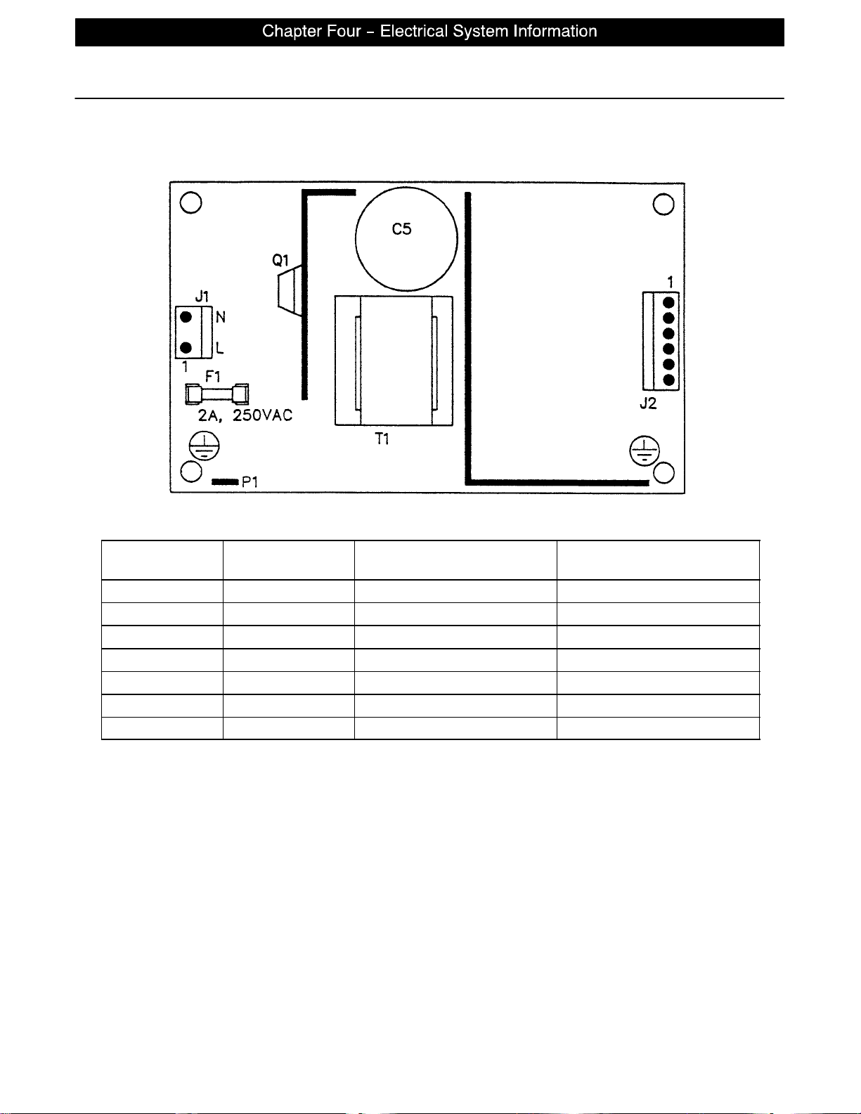
POWER SUPPLY − P/N 59−157
Power Supply
CONNECTOR
LOCATION
J1 110V Pin 1 Pin 2
J2 12V Pin 1 Pin 4 or 5
J2 5V Pin 2 Pin 4 or 5
J2 5V Pin 3 Pin 4 or 5
J2 GND Pin 4 Pin 4 or 5
J2 GND Pin 5 Pin 4 or 5
J2 −12V Pin 6 Pin 4 or 5
VOLTAGE POSITIVE LEAD NEGATIVE LEAD
page 4−4
Page 26

ELECTRICAL COMPONENTS
CPU KIT 2033−700−002
FOOT BOARD KEYBOARD (S/R LIGHTS, LOCKOUTS, ETC.) 3001−500−930
FOOT BOARD SCALE DISPLAY 3001−507−900
FOOT BOARD SCALE KEYBOARD 3001−507−910
FOOT BOARD BED EXIT KEYBOARD 3001−508−900
POWER SUPPLY 59−157
SIDERAIL BOARDS
INSIDE BOARD 3001−400−930
OUTSIDE BOARD 3001−400−910
SPEAKER W/CABLE 3000−403−831
OTHER COMPONENTS
CAPACITOR, FOWLER & GATCH 59−779
CAPACITOR, LIFT 59−778
CASTER, 8” 3001−200−90
CASTER, STEER, 8 ” 3001−200−80
COIL CORD, LIFT POWER 3001−200−864
COIL CORD, LIFT SENSOR 3001−200−815
ISOLATION PLATE KIT, LIFT MOTOR 3000−200−723
LOAD CELL 3001−307−57
MOTOR COUPLER KIT, LIFT 3000−200−725
MOTOR, FOWLER & GATCH W/CLUTCH 3001−300−705
MOTOR, LIFT (SAME FOR HEAD AND FOOT END) 3000−200−213
PAINT, TOUCH−UP, OPAL, BOTTLE W/BRUSH 7000−1−321
PAINT, TOUCH−UP, OPAL, SPRAY CAN 7000−1−318
POTENTIOMETER, FOOT END 3001−200−230
POTENTIOMETER, FOWLER W/CABLE 2035−32−803
POTENTIOMETER, HEAD END 3001−200−240
POWER CORD 39−254
SIDERAIL COVER, RIGHT 3000−336−11
SIDERAIL COVER, LEFT 3000−336−12
SINGLE TUBE OF GREASE 3000−200−700
page 5−1
Page 27

Notes
page 5−2
Page 28

GENERAL INFORMATION
This section contains tool lists and step−by−step procedures to assist with the maintenance and servicing
of the base portion of your equipment.
In the text, the words “right” and “left” refer to the right and left sides of a patient lying face up on the bed.
BASE MAINTENANCE CONTENTS
Static Discharge Precautions 6−2. . . . . . . . . . . . . . . . . . . . . . . . . . . . . . . . . . . . . . . . . . . . . . . . . . . . . . . . . . . .
Brake Pedal Replacement 6−3. . . . . . . . . . . . . . . . . . . . . . . . . . . . . . . . . . . . . . . . . . . . . . . . . . . . . . . . . . . . . . .
Lift Motor and Capacitor Removal and Replacement 6−4. . . . . . . . . . . . . . . . . . . . . . . . . . . . . . . . . . . . . . . .
Lift Housing Removal and Replacement 6−5, 6−6. . . . . . . . . . . . . . . . . . . . . . . . . . . . . . . . . . . . . . . . . . . . . . .
Lift Potentiometer Replacement and Adjustment 6−7, 6−8. . . . . . . . . . . . . . . . . . . . . . . . . . . . . . . . . . . . . . . .
Lift Potentiometer “Burn−In” Procedure 6−8. . . . . . . . . . . . . . . . . . . . . . . . . . . . . . . . . . . . . . . . . . . . . . . . . . . .
Lift Motor Coupler Replacement 6−9. . . . . . . . . . . . . . . . . . . . . . . . . . . . . . . . . . . . . . . . . . . . . . . . . . . . . . . . . .
Power and Sensor Coil Cord Replacement 6−10, 6−11. . . . . . . . . . . . . . . . . . . . . . . . . . . . . . . . . . . . . . . . . .
page 6−1
Page 29
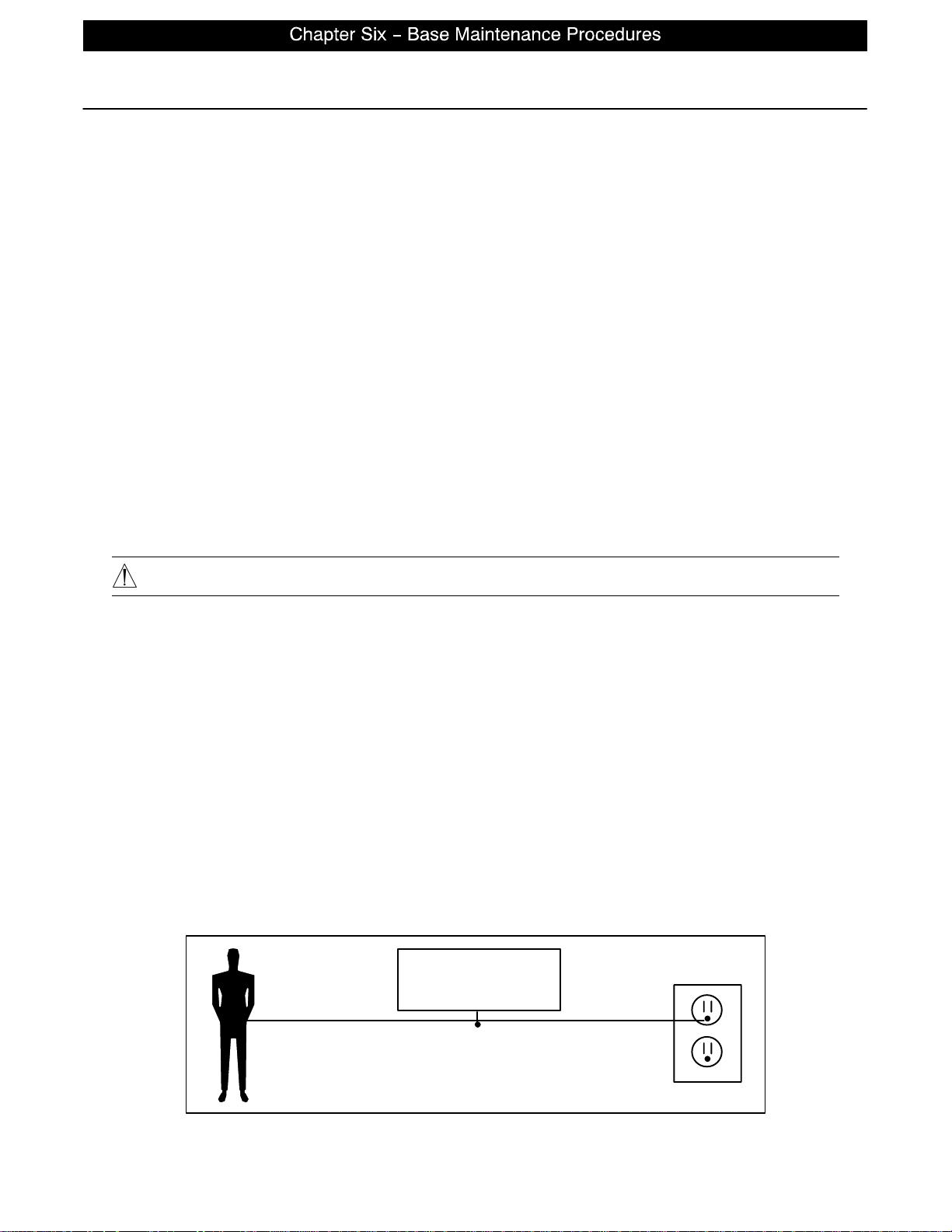
Static Discharge Precautions
The electronic circuits in the 2030 are completely protected from static electricity damage only while the bed
is assembled. It is extremely important that all service personnel always use adequate static protection when
servicing the electronic systems of the 2030. Whenever you are touching wires, you should be using static
protection.
Static Protection Equipment
The necessary equipment for proper static protection is:
S 1 static wrist strap; 3M part number 2214 or equivalent,
S 1 grounding plug; 3M part number 61038 or equivalent,
S 1 test lead with a banana plug on one end and an alligator clip on the other; Smith part number
N132B699 or equivalent.
Stryker has available the following equipment for proper static protection:
S Complete static protection system − part number 3000−000−753
S 1 grounding plug − part number 3000−000−754
S 1 static wrist strap − part number 3000−000−755
S 1 test lead − part number 3000−000−756
CAUTION
All electronic service parts will be shipped in static shielding bags. Do not open the bags until you have completed steps 2 and 3 of the following procedure. Do not place unprotected circuit boards on the floor. All circuit
boards to be returned to Stryker Medical should be shipped in the static shielding bags the new boards were
shipped in.
Static Protection Procedure
1. Unplug the power cord from the wall receptacle.
2. Insert the grounding plug into a properly grounded hospital grade wall receptacle. Plug the banana plug
of the test lead into the receptacle on the grounding plug. Connect the alligator clip on the other end of
the test lead to a ground point on the bed.
3. Place the static control wrist strap on your wrist. Connect the alligator clip at the other end of the wrist strap
cord to a ground point on the bed.
BED
page 6−2
GROUNDING DIAGRAM
Page 30

Brake Pedal Replacement
Required Tools:
5/16” Hex Allen Wrench Torque Wrench Loctite 242
Hammer Punch #2 Phillips Screwdriver
Bungee Cords (or Equivalent)
Procedure:
8. Raise the litter to the full up position.
9. Unplug the bed power cord from the wall socket.
10. Using a #2 Phillips screwdriver, remove the three screws holding both the head end and the foot end upper lift covers. If you want, hold the covers out of the way by using bungee cords (or the equivalent) to
secure them to the litter top.
11. Using a 5/16” hex Allen wrench, remove the two bolts holding the brake pedal to the brake rod.
12. Using a hammer and punch, remove the roll pins holding the brake shaft crank to the brake rod on both
the head and the foot end.
13. Push the brake rod through the frame until the brake pedal is clear. Remove the brake pedal.
14. Reverse the above steps to attach the new brake pedal.
NOTE
Use Loctite 242 when reinstalling the bolts and torque the bolts to 25 foot−pounds.
page 6−3
Page 31
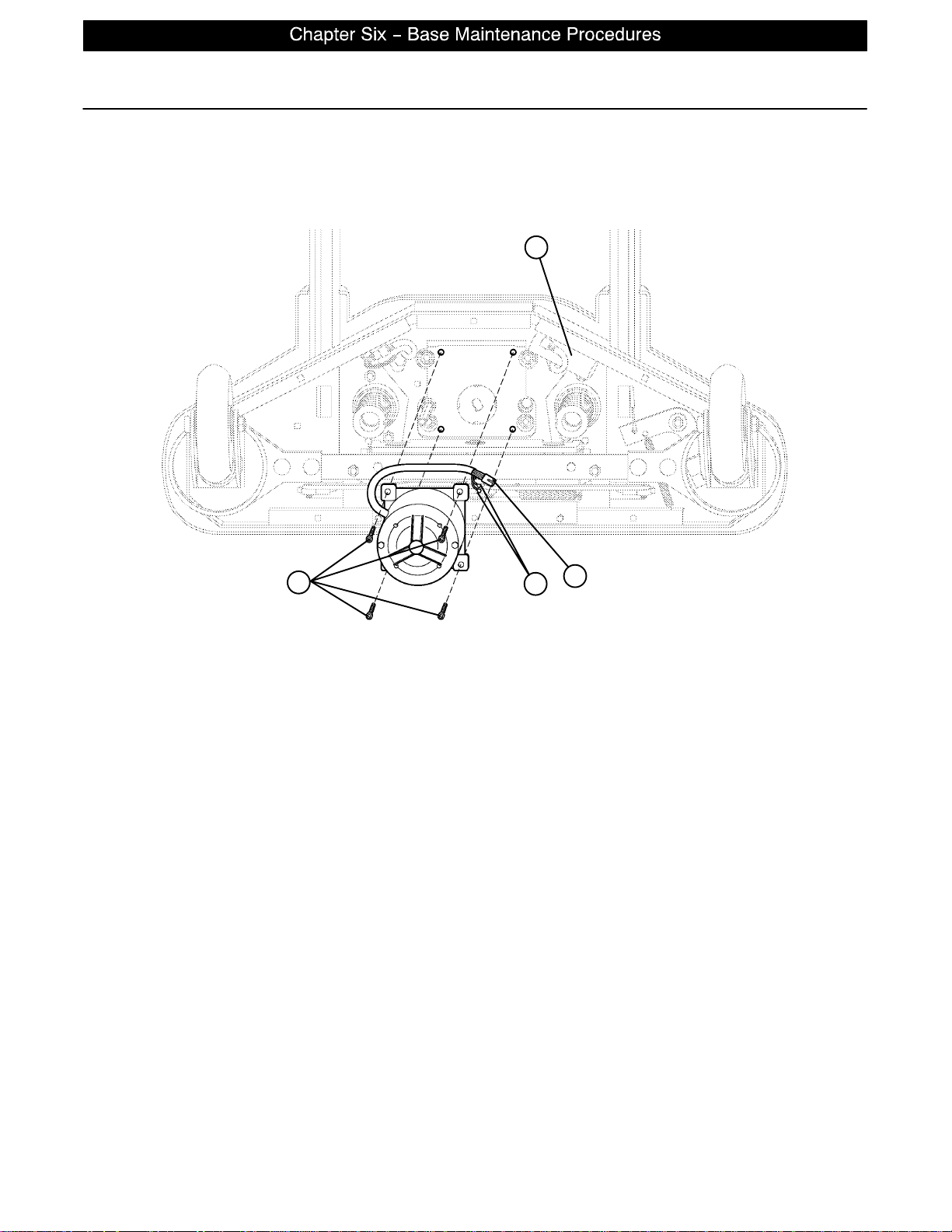
Lift Motor and Capacitor Removal and Replacement
Required Tools:
3/8” Socket Wrench w/Extension 5/16” Socket Wrench Floor Jack
Side Cutters 7/16” Open End Wrench 2x4 (or Equivalent)
C
D
B
A
FOOT END
Procedure:
NOTE
If you need more space to work under the base frame, place a 2x4 across the base frame rails and use a
floor jack to raise the base frame off the floor.
1. Unplug the bed power cord from the wall socket. Using a 5/16 ” socket wrench, remove the five bolts
holding the lower lift cover to the base and remove the cover.
2. Disconnect the two connectors (A) at the motor capacitor.
3. Disconnect the white connector (B) from the power cord.
4. Using side cutters, cut the cable ties holding the capacitor (C) to the base and remove the capacitor.
5. Using a 3/8” socket wrench, remove the four screws (D) holding the motor assembly in the lift housing
and remove the motor assembly.
6. Reverse the above steps to install the new motor.
NOTE
The drive shaft on the new motor probably will have to be turned to be aligned with the coupler. Use a 7/16”
open end wrench to turn the drive shaft of the motor.
The procedure for lift motor and capacitor removal and replacement is the same for both ends of the bed.
page 6−4
Page 32

Lift Housing Removal and Replacement
Required Tools:
#2 Phillips Screwdriver Bungee Cord (or Equivalent) 5/16” Socket Wrench
Side Cutters 9/16” Socket Wrench Floor Jack
7/32” Hex Allen Socket Wrench Sawhorses (or Equivalent) 2x4 (or Equivalent)
3/8” Socket Wrench (w/ 6” extension)
Procedure:
NOTE
If you need more space to work under the base frame, place a 2x4 across the base frame rails and use a
floor jack to raise the base frame off the floor.
1. Unplug the bed power cord from the wall socket.
2. Using a 5/16” socket wrench, remove the five bolts holding the lower lift cover to the base and remove
the cover.
3. Using a #2 Phillips screwdriver, remove the three screws holding the upper lift cover to the base. If you
want, hold the covers out of the way by using bungee cords (or the equivalent) to secure them to the litter
top.
4. Remove the lift motor and capacitor (refer to procedure on p age 6−4).
5. Remove lift potentiometer (refer to procedure on p age 6−7).
6. Using a 5/16” socket wrench, remove the cable clamps holding the power and sensor coil cords on top
of the lift housing assembly. Cut the cable ties and disconnect the coil cords from under the lift housing.
The power and sensor coil cords are now free of the lift housing assembly. Drape them up out of the way.
7. Using a 7/32 ” hex Allen socket, remove the two screws holding the lift screws to the header crossbar
plate.
8. Lift the litter top up and support it about 6” above the lift screws with sawhorses or the equivalent.
page 6−5
Page 33
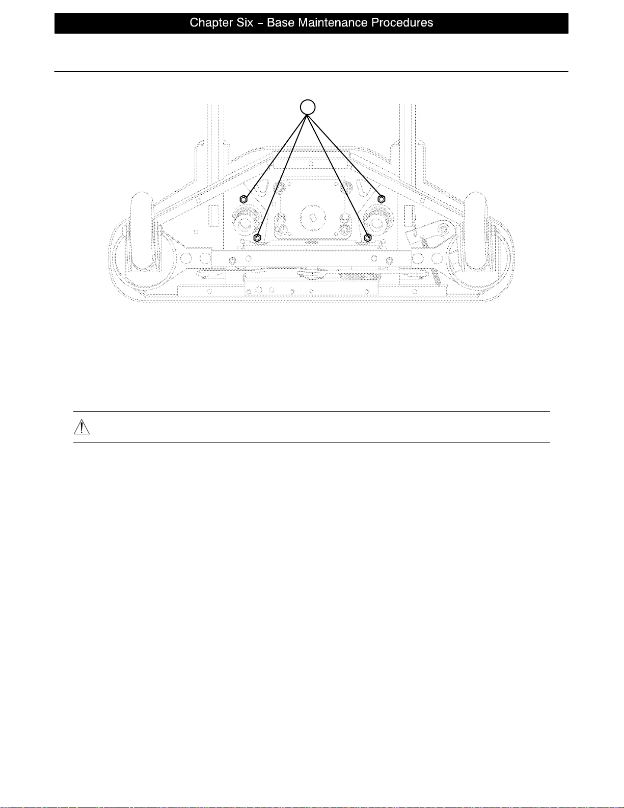
Lift Housing Removal and Replacement (Continued)
A
FOOT END − BOTTOM VIEW
9. Under the base, using a 9/16” socket, remove the four nuts (A) holding the lift housing to the base.
10. Lift up and out on the lift housing assembly to remove it from the base.
CAUTION
To ensure proper reattachment of the power and sensor coil cords, refer to the procedure on page 6−10.
Refer to the procedure on page 6−7 for reattachment of the lift potentiometer.
11. Reverse the above steps to reinstall the lift housing assembly after service is completed.
NOTE
The procedure for lift housing removal and replacement is the same for both ends of the bed.
page 6−6
Page 34
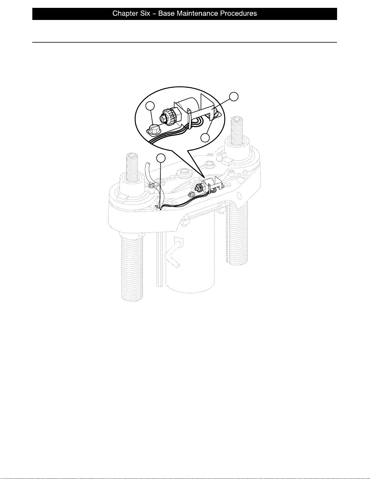
Lift Potentiometer Replacement and Adjustment
Required Tools:
#2 Phillips Screwdriver Bungee Cord (or equivalent) 5/16” Socket Wrench
3/8” Open End Wrench Side Cutters
C
B
B
A
Procedure:
1. Raise the litter to the full up position.
2. Unplug the bed power cord from the wall socket.
3. Using a 5/16” socket wrench, remove the five bolts holding the lower lift cover to the base and remove
the cover. If you want, hold the covers out of the way by using bungee cords (or the equivalent) to secure
them to the litter top.
4. Using a #2 Phillips screwdriver, remove the three screws holding the upper lift cover to the base. If you
want, hold the covers out of the way by using bungee cords (or the equivalent) to secure them to the litter
top.
5. Using side cutters, cut the cable tie (A) holding the pot cable to the coil cord.
6. Unplug the pot cable from the sensor coil cord. If replacing a pot at the head end of the bed, unplug the
cables attached to the brake sensor switch.
7. Pull the pot cable up through the base.
8. Using a 3/8” open end wrench, remove the two bolts (B) holding the pot housing (C) to the lift housing.
page 6−7
Page 35

Lift Potentiometer Replacement and Adjustment (Continued)
9. Lift up and out on the pot housing assembly to remove it from the lift housing.
10. Before installing the new pot on the bed, turn it clockwise until it stops. T urn it back counterclockwise
two full (360_) revolutions. This allows a ”window” position for proper upper and lower limits.
11. Reverse steps 4−8 to install the new pot and pot housing assembly.
12. After installing the new pot, the “burn−in” procedure below must be followed.
NOTE
Be sure to maintain the pot position while installing.
Lift Potentiometer ”Burn−In” Procedure
1. Unplug the bed power cord from the wall socket.
2. On the foot board control panel, press and hold down the Bed Motion On/Off button and the Knee button
simultaneously.
3. While holding down the above two buttons, plug the power cord into the wall socket. The lights on the
foot board control panel should flash, indicating the bed is in the diagnostics mode.
4. Press and hold the Bed Motion Up button until the litter raises completely.
5. Press and hold the Bed Motion Lock button until the lights flash. The bed upper limit is set.
6. Release the button, unplug the bed power cord from the wall socket and turn battery backup off.
7. Plug the power cord back in to the wall socket.
8. Unplug the bed power cord from the wall socket.
9. On the foot board control panel, press and hold down the Bed Motion On/Off button and the Knee button
simultaneously.
10. While holding down the above two buttons, plug the power cord into the wall socket. The lights on the
foot board control panel should flash, indicating the bed is in the diagnostics mode.
11. Raise or lower the bed height until the litter surface is 21.5” above the floor. Hold down the Up/Down Lock
button until the light flashes.
12. Plug the power cord back in to the wall socket. Run the bed to full up, then full down and verify the bed
limits with a tape measure.
page 6−8
Page 36
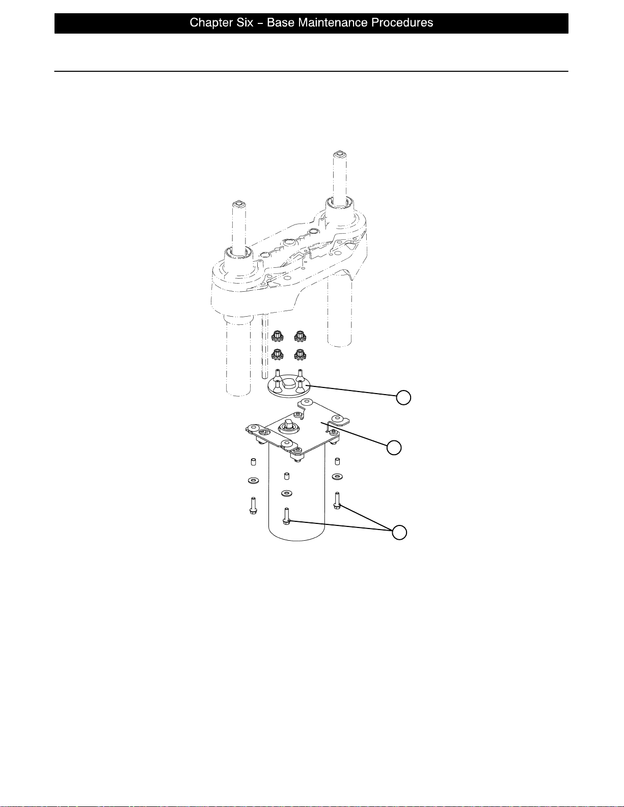
Lift Motor Coupler Replacement
Required Tools:
5/16” Socket Wrench 3/8” Socket Wrench (w/6” Extension) Floor Jack
2x4 (or Equivalent)
C
B
A
Procedure:
NOTE
If you need more space to work under the base frame, place a 2x4 across the base frame rails and use a
floor jack to raise the base frame off the floor.
1. Unplug the bed power cord from the wall socket.
2. Using a 5/16” socket wrench, remove the five bolts holding the lower lift cover to the base and remove
the cover.
3. Using a 3/8” socket with an extension, remove the four bolts (A) holding the isolation plate (B) to the lift
housing and lower the lift motor and isolation plate assembly to allow access to the coupler (C).
4. The motor coupler can now be removed from the lift housing.
5. Reverse the above steps to install the new motor coupler and bushings.
page 6−9
Page 37

Power and Sensor Coil Cord Replacement
Required Tools:
#2 Phillips Screwdriver Side Cutters 5/16” Socket Wrench
Bungee Cord (or equivalent) 5/16” Nut Driver Floor Jack
2x4 (or Equivalent)
Procedure:
NOTE
If you need more space to work under the base frame, place a 2x4 across the base frame rails and use a
floor jack to raise the base frame off the floor.
1. Unplug the bed power cord from the wall socket.
2. Using a 5/16” socket wrench, remove the five bolts holding the lower lift cover to the base and remove
the cover.
3. Using a #2 Phillips screwdriver, remove the three screws holding the upper lift cover to the base. If you
want, hold the covers out of the way by using bungee cords (or the equivalent) to secure them to the litter
top.
4. Using side cutters, cut the cable ties holding the power and sensor coil cords to the base. Remove the
ground wire coming from the sensor cord that is attached to the base (note the star washer arrangement).
5. Disconnect the cables going to the motor and the lift potentiometer (at the head end, the sensor cord is
also attached to the brake switch sensor).
6. Pull both cords up through the frame of the bed and the lift housing.
7. Using a 5/16” socket wrench, remove the two screws (A) holding the cable clamps* to the top of the lift
housing.
8. Using a 5/16” socket wrench, remove the two screws (B) securing the cable clamps* to the underside
of the header crossbar assembly.
9. Pull both coil cords up through the header crossbar assembly.
10. Disconnect the power and sensor coil cords from the connectors.
11. The cords should now be completely removed from the bed. Reverse the above steps to install the new
power and sensor cords.*
CAUTION
* When the power and sensor coil cords are being replaced, secure the cable clamps to the cords at the first
coil both on the top and on the bottom to assure there is not too much slack in the cords between the top of
the lift housing assembly and the bottom of the header crossbar. Be sure the clamps are fastened at exactly
the correct angle, as shown by the arrows in the illustration. Arrange the cords exactly as shown in the illustra-
tion (left in front of right). If this is not done correctly, damage to the cords will result.
page 6−10
Page 38
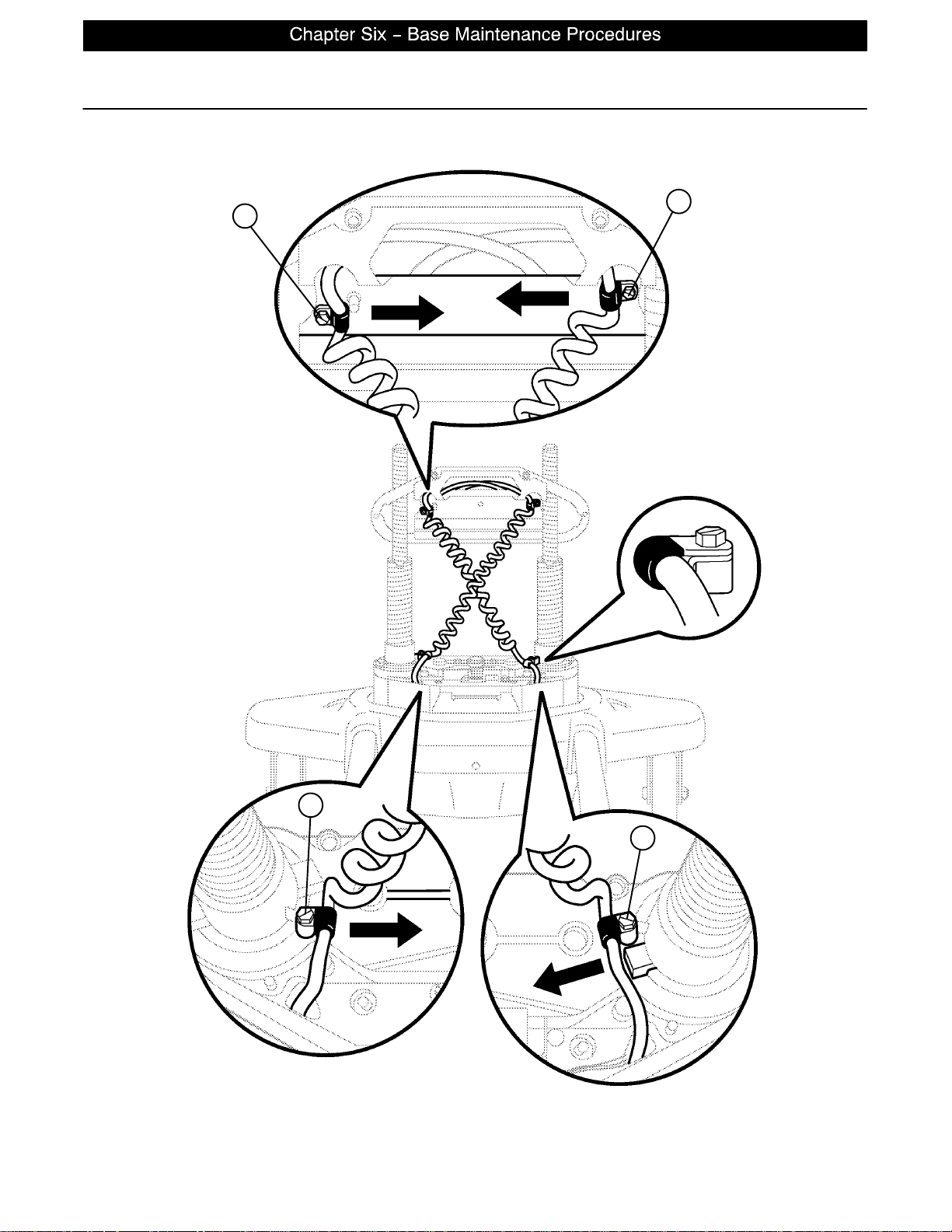
Power and Sensor Coil Cord Replacement Illustration
B
B
A
A
VIEW FROM CENTER OF BED
page 6−11
Page 39

Notes
page 6−12
Page 40

GENERAL INFORMATION
This section contains tool lists and step−by−step procedures to assist with the maintenance and servicing
of the litter portion of your equipment.
In the text, the words “right” and “left” refer to the right and left sides of a patient lying face up on the bed.
LITTER MAINTENANCE CONTENTS
Scale System Diagnostics and Calibration 7−2, 7−3. . . . . . . . . . . . . . . . . . . . . . . . . . . . . . . . . . . . . . . . . . . . .
Load Cell Replacement 7−4. . . . . . . . . . . . . . . . . . . . . . . . . . . . . . . . . . . . . . . . . . . . . . . . . . . . . . . . . . . . . . . . .
Head Motor Removal and Replacement 7−4. . . . . . . . . . . . . . . . . . . . . . . . . . . . . . . . . . . . . . . . . . . . . . . . . . .
Knee Motor Removal and Replacement 7−5. . . . . . . . . . . . . . . . . . . . . . . . . . . . . . . . . . . . . . . . . . . . . . . . . . .
Power Supply Removal and Replacement 7−6. . . . . . . . . . . . . . . . . . . . . . . . . . . . . . . . . . . . . . . . . . . . . . . . .
CPU Board Removal and Replacement 7−6. . . . . . . . . . . . . . . . . . . . . . . . . . . . . . . . . . . . . . . . . . . . . . . . . . .
Fowler Potentiometer Replacement 7−7. . . . . . . . . . . . . . . . . . . . . . . . . . . . . . . . . . . . . . . . . . . . . . . . . . . . . . .
Fowler and Lift Potentiometer “Burn−In” Procedure 7−8. . . . . . . . . . . . . . . . . . . . . . . . . . . . . . . . . . . . . . . . .
page 7−1
Page 41

Scale System Diagnostics and Calibration
Diagnostic Mode Functions:
1. Calibrate Scale: This is required in the field if a CPU board or a load cell is replaced.
2. Display Corner: This function displays the individual reference numbers for each load cell assembly and
can be used to isolate a defective load cell.
3. Init. to Defaults: This may be required in the field when replacing a CPU board or a load cell.
4. Erase E−prom: This is a factory setting not used in the field.
5. Display Factor: This is a factory setting not used in the field.
5. Exit Diagnostics: Changes made in the diagnostic mode must be saved in permanent memory using this
function. Switching off power without saving will reset all variables to their previous values.
Diagnostic Mode:
NOTE
It requires two people to enable the diagnostic mode for the scale system.
1. To enter diagnostic mode, unplug the bed’s power cord from the wall socket.
2. Press and hold down the LBS/KGS button.
3. While still holding the LBS/KGS button, plug the bed’s power cord into the wall socket.
4. After two seconds, release the LBS/KGS button. The LCD should display “CALIBRATE SCALE”. The
diagnostic mode is now active.
Displaying Individual Load Cell Outputs:
A defective load cell can be detected by entering diagnostics and displaying individual load cell outputs.
1. Enter the diagnostic mode. The LCD will display “CALIBRATE SCALE” when the diagnostic mode is activated.
2. Repeatedly press and release the up or down arrow button (ZERO or SCALE ON/OFF) until the LCD displays “DISPLAY CORNER”.
3. Press and release the ENTER button (LBS/KGS). The LCD should display “PICK CORNER NOW”.
The four buttons listed in the group below function as POSITION buttons corresponding with the four corners of the bed’s litter. Whenever the LCD displays “PICK CORNER NOW”, press one of these buttons
to select the load cell assembly at the desired corner.
A. ZERO = head end, patient’s left side
B. CHANGE EQUIP. = head end, patient’s right side
C. TREND/FOWLER ANGLE = foot end, patient ’s right side
D. LBS/KGS = foot end, patient’s left side
4. Press and release the position button that corresponds with the load cell to be checked. The LCD should
display “X/X=NNN.N”. ”X/X” represents the initials of the selected corner , i.e. H/R will be displayed for
the patient’s head end, right side. ”NNN.N” represents the resistance of the load cell.
5. Repeat step four for each corner. Head end weight readings will normally be lower than foot end weights.
Weight readings should be constant. A drifting 000.0 or 999.9 weight, or a reading that does not change
when weight is applied to that corner of the bed indicates a problem with the selected load cell assembly
or load cell cable.
6. When all the load cell outputs have been checked, repeatedly press and release the SCALE ON/OFF button until the LCD displays “EXIT DIAGNOSTICS”. Press the ENTER button (LBS/KGS) to exit diagnostics.
page 7−2
Page 42

Scale System Diagnostics and Calibration
Verifying Scale Accuracy:
1. Zero the empty bed. Place a known weight on the center of the bed; the heavier the better and no less
than 100 pounds. The displayed weight should be within 1% of the actual weight.
2. If the displayed weight is not accurate, remove the weight from the bed and proceed to the Scale Calibration
section.
Scale Calibration:
NOTE
It requires two people to enable the calibration mode for the scale system.
Raise the siderails when calibrating the scale to avoid getting inaccurate scale readings due to possible interference between the siderails and the casters.
Calibrate the scale system with a known 200 pound weight. If exactly 200 pounds is not available, the factory
default for calibration will have to be changed as described in step 8.
1. To enter the calibration mode, unplug the bed’s power cord from the wall socket.
2. Press and hold down the LBS/KGS button.
3. While still holding the LBS/KGS button, plug the bed’s power cord into the wall socket.
4. After two seconds, release the LBS/KGS button. The LCD should read “CALIBRATE SCALE”. The cal-
ibration mode is now active.
5. Using the up or down arrow button (ZERO or SCALE ON/OFF), toggle through the menu until “INIT. TO
DEFAULTS” is displayed. Press and hold the ENTER button (LBS/KGS) until “SAVING DEFAULTS” is
displayed. Release the ENTER button.
6. Using the up or down arrow buttons (ZERO or SCALE ON/OFF), toggle through the menu until “CALI-
BRATE SCALE” is displayed.
7. Press and hold the ENTER button (LBS/KGS). Zero the bed, following the displayed instructions. When
the bed is zeroed, the LCD should display “REF X100=<2 0000”. This is the factory default for 200
pounds. If 200 pounds will be used to calibrate the scale, proceed to step 9.
8. If exactly 200 pounds is not available, change the display to match the weight you are using. Pressing
the TREND/FOWLER ANGLE button will move the cursor position to the right. Pressing the up arrow
(ZERO) button will increase the numbers. Pressing the down arrow (SCALE ON/OFF) button will decrease the numbers. Scroll through the numbers until they match the weight you will use for calibration.
9. Press and release the ENTER button and the LCD will display “PRESS REV. TREND”. Press the button
with the Reverse Trendelenburg symbol (feet down/head up) until the bed reaches full reverse Trend.
Release the button and the LCD will display “DO NOT TOUCH BED”.
10. The LCD will display “PRESS TREND.” Press the button with the Trendelenburg symbol (feet up/head
down) until the bed reaches full trend. Release the button and the LCD will display “DO NOT TOUCH
BED”.
11. The LCD will display “CALIBRATE SCALE”. This indicates the calibration procedure is complete.
12. Exit scale calibration by pressing the up arrow button (ZERO) until the LCD displays “EXIT DIAGNOS-
TICS”. Press the ENTER (LBS/KGS) button to exit.
13. Level the bed at a full up or full down position. Remove the weight and zero the bed.
14. Verify scale accuracy and functionality before returning the bed to service.
page 7−3
Page 43

Load Cell Replacement
Required Tools:
9/16” Socket Wrench 9/16” Open End Wrench Saw Horse (or Equivalent)
Wire Cutters
Replacement Procedure:
1. Raise the Fowler or knee section, depending which end of the litter needs service.
2. Unplug the load cell connector from the load cell cable.
3. Using wire cutters, remove the wire ties holding the cable to the frame.
4. Using a 9/16” socket and a 9/16” open end wrench, remove the two bolts holding the load cell to the litter
cross tube and remove the load cell.
5. Using a saw horse, support the litter at the end where the load cell was removed. Reverse the above
procedure to install the new load cell.
NOTE
Scale calibration procedure must be performed after the load cell is replaced (see page 7−3).
Head Motor Removal and Replacement
Required Tools:
T27 Torx 7/16” Socket Wrench 3/8” Socket Wrench
Wire Cutters
Procedure:
1. Run the litter to the full up position and remove the mattress from the bed.
2. Fold the foot section back toward the head end of the bed. Electrically run the knee section to full up.
If the knee section will not move electrically, pull the foot section toward the head end of the bed while
pulling the CPR release handle (located at the head end of the bed). The knee section will raise.
3. Using a T27 torx, remove the four screws holding the cover to the actuator box and remove the cover.
4. Remove the two CPR release cables from the CPR release bracket. Using a 3/8” socket wrench under-
neath the actuator box, remove the two bolts holding the release bracket to the actuator box and remove
the bracket from the actuator box.
5. Disconnect all the electrical connections going to the head motor and move aside any wiring that could
interfere with the removal of the motor.
6. Using a 3/8” socket wrench underneath the actuator box, remove the four bolts holding the motor mount-
ing bracket to the actuator box. Lift up and out on the motor to remove it.
7. Remove the motor mounting bracket from the old motor and install it on the replacement motor.
8. Reverse steps 3 through 6 to install the replacement motor.
9. Verify the bed is working properly before returning it to service.
page 7−4
Page 44

Knee Motor Removal and Replacement
Required Tools:
T27 Torx 7/16” Socket Wrench 3/8” Socket Wrench
Wire Cutters
Procedure:
1. Run the litter to the full up position and remove the mattress from the bed.
2. Fold the foot section back toward the head end of the bed. Electrically run the knee section to full up.
If the knee section will not move electrically, pull the foot section toward the head end of the bed while
pulling the CPR release handle (located at the head end of the bed). The knee section will raise.
3. Using a 7/16’ socket wrench, remove the mounting bolt on the litter for the knee dampening cylinder. This
leaves the knee dampener mounted only to the seat panel.
4. Using a T27 torx, remove the four screws holding the cover to the actuator box and remove the cover.
5. Remove the two CPR release cables from the CPR release bracket. Using a 3/8” socket wrench under-
neath the actuator box, remove the two bolts holding the release bracket to the actuator box and remove
the bracket from the actuator box.
6. Disconnect all the electrical connections going to the knee motor and move aside any wiring that could
interfere with the removal of the motor.
7. Pull the foot panel toward the head end of the bed. This causes the knee motor linkage to roll past center
and allows the motor to be removed without supporting the knee section.
8. Using a 3/8” socket wrench underneath the actuator box, remove the four bolts holding the motor mount-
ing bracket to the actuator box. Lift up and out on the motor to remove it.
9. Remove the motor mounting bracket from the old motor and install it on the replacement motor.
10. Install the replacement motor.
11. Reverse step 3 − 5 to reinstall the knee dampener, CPR bracket and actuator box cover.
12. Pull the foot panel toward the foot end of the bed. This causes the knee motor linkage to roll back past
center. If this step is not done, damage to the motor or linkage will occur .
13. Verify the bed is working properly before returning it to service.
page 7−5
Page 45

Power Supply Removal and Replacement
Required Tools:
T27 Torx Needle−Nose Pliers
Procedure:
1. Run the litter to the full up position and remove the mattress from the bed.
2. Fold the foot section back toward the head end of the bed. Electrically run the knee section to full up.
If the knee section will not move electrically, pull the foot section toward the head end of the bed while
pulling the CPR release handle (located at the head end of the bed). The knee section will raise.
3. Using a T27 torx, remove the four screws holding the cover to the actuator box and remove the cover.
4. Properly ground yourself (see page 6−2)
5. Unplug all electrical connections from the power supply.
6. Using needle−nose pliers, squeeze the four stand−offs supporting the power supply and pull up gently
on the power supply to remove it.
7. Reverse steps 2 through 5 to install the new power supply.
8. Verify the bed is working properly before returning it to service.
CPU Board Removal and Replacement
Required Tools:
T27 Torx Needle−Nose Pliers
Replacement Procedure:
1. Run the litter to the full up position and remove the mattress from the bed.
2. Fold the foot section back toward the head end of the bed. Electrically run the knee section to full up.
If the knee section will not move electrically, pull the foot section toward the head end of the bed while
pulling the CPR release handle (located at the head end of the bed). The knee section will raise.
3. Using a T27 torx, remove the four screws holding the cover to the actuator box and remove the cover.
4. Properly ground yourself (see page 6−2)
5. Unplug all electrical connections from the CPU board.
6. Press the six stand−offs away from the board while gently lifting the board up and out.
7. Install the replacement CPU board.
NOTE
After the replacement CPU board is installed, a “burn−in” procedure must be performed for the Fowler and
lift motor potentiometers (see page 7−8)
If the bed is equipped with a scale system, a scale calibration procedure must also be performed after the
replacement CPU board is installed (see page 7−3).
page 7−6
Page 46

Fowler Potentiometer Replacement
Required Tools:
T27 Torx Wire Cutters 1/2” Open End Wrench
7/64” Allen Wrench
Replacement Procedure:
1. Manually crank the knee section up until it stops.
2. Using a T27 Torx, remove the four screws holding the litter access cover to the litter and remove the cover.
3. Using a 7/64” Allen wrench, loosen the screw holding the linkage to the pot. shaft and remove the linkage
from the shaft.
4. Using a 1/2” open end wrench, remove the nut holding the potentiometer to the frame.
5. Using wire cutters, remove the cable ties from the cable. Unplug the cable from the CPU and remove the
pot.
6. Reverse the above procedure to install the replacement potentiometer.
7. The new potentiometer must be calibrated after it has been installed.
8. The Fowler pot. should be set at 150 ohms ($ 10 ohms) in the full down position. This reading must be
taken from pins 3 and 4 on the connector with the pot. unplugged from the board. After the correct ohm
reading is achieved, tighten the screw on the linkage.
9. Press and hold the “Knee Lockout” and “Bed Motion Lock” buttons on the foot board.
10. Plug the power cord into the wall socket. Release the two buttons and the “Knee Lockout” LED should
be flashing. This indicates the bed is in the correct calibration mode.
11. Using the foot board controls, run the Fowler up to 90_. Press and hold the button on the foot board to
lock out the siderail controls for the back until the padlock LED flashes. Release the button.
12. Using the foot board controls, run the Fowler down to 0_. Press and hold the button on the foot board
to lock out the siderail controls for the knee until the padlock LED flashes. Release the button and unplug
the bed power cord to complete the “burn in” mode.
13. Plug the bed power cord into the wall socket and verify the back limits are set properly before returning
the bed to service.
page 7−7
Page 47

Fowler and Lift Potentiometer ”Burn−In” Procedure
NOTE
It requires two people to enable the diagnostics mode for the bed.
1. Unplug the bed power cord from the wall socket.
2. On the foot board control panel, hold down the bed motion lock button and the button to lock out the siderail controls for the knee. While still holding the buttons, plug the bed power cord into the wall socket.
Release the foot board buttons. The siderail control lights LED should be flashing to indicate the bed is
in diagnostics mode.
3. Using the foot board controls, run the Fowler up to 90_. Press and hold the button on the foot board to
lock out the siderail controls for the back until the padlock LED flashes. Release the button.
4. Using the foot board controls, run the Fowler down to 0_. Press and hold the button on the foot board
to lock out the siderail controls for the knee until the padlock LED flashes. Release the button..
5. To “burn in” the Bed Up/Down limits, unplug the bed power cord from the wall socket.
6. On the foot board control panel, press and hold down the Bed Motion On/Off button and the Knee button
simultaneously.
7. While holding down the above two buttons, plug the power cord into the wall socket. The lights on the
foot board control panel should flash, indicating the bed is in the diagnostics mode.
8. Press and hold the Bed Motion Up button until the litter raises completely.
9. Press and hold the Bed Motion Lock button until the lights flash. The bed upper limit is set.
10. Release the button, unplug the bed power cord from the wall socket and turn battery backup off.
11. Plug the power cord back in to the wall socket.
12. Unplug the bed power cord from the wall socket.
13. On the foot board control panel, press and hold down the Bed Motion On/Off button and the Knee button
simultaneously.
14. While holding down the above two buttons, plug the power cord into the wall socket. The lights on the
foot board control panel should flash, indicating the bed is in the diagnostics mode.
15. Raise or lower the bed height until the litter surface is 21.5” above the floor. Hold down the Up/Down Lock
button until the light flashes.
16. Plug the power cord back in to the wall socket. Run the bed to full up, then full down and verify the bed
limits with a tape measure.
page 7−8
Page 48

GENERAL INFORMATION
This section contains tool lists and step−by−step procedures to assist with the maintenance and servicing
of the siderail portion of your equipment.
In the text, the words “right” and “left” refer to the right and left sides of a patient lying face up on the bed.
SIDERAIL MAINTENANCE CONTENTS
Head and Foot End Siderail Cover Removal 8−2. . . . . . . . . . . . . . . . . . . . . . . . . . . . . . . . . . . . . . . . . . . . . . .
Head and Foot Molded Siderail Replacement 8−3. . . . . . . . . . . . . . . . . . . . . . . . . . . . . . . . . . . . . . . . . . . . . .
Head End Siderail Cable Replacement 8−4, 8−5. . . . . . . . . . . . . . . . . . . . . . . . . . . . . . . . . . . . . . . . . . . . . . . .
page 8−1
Page 49
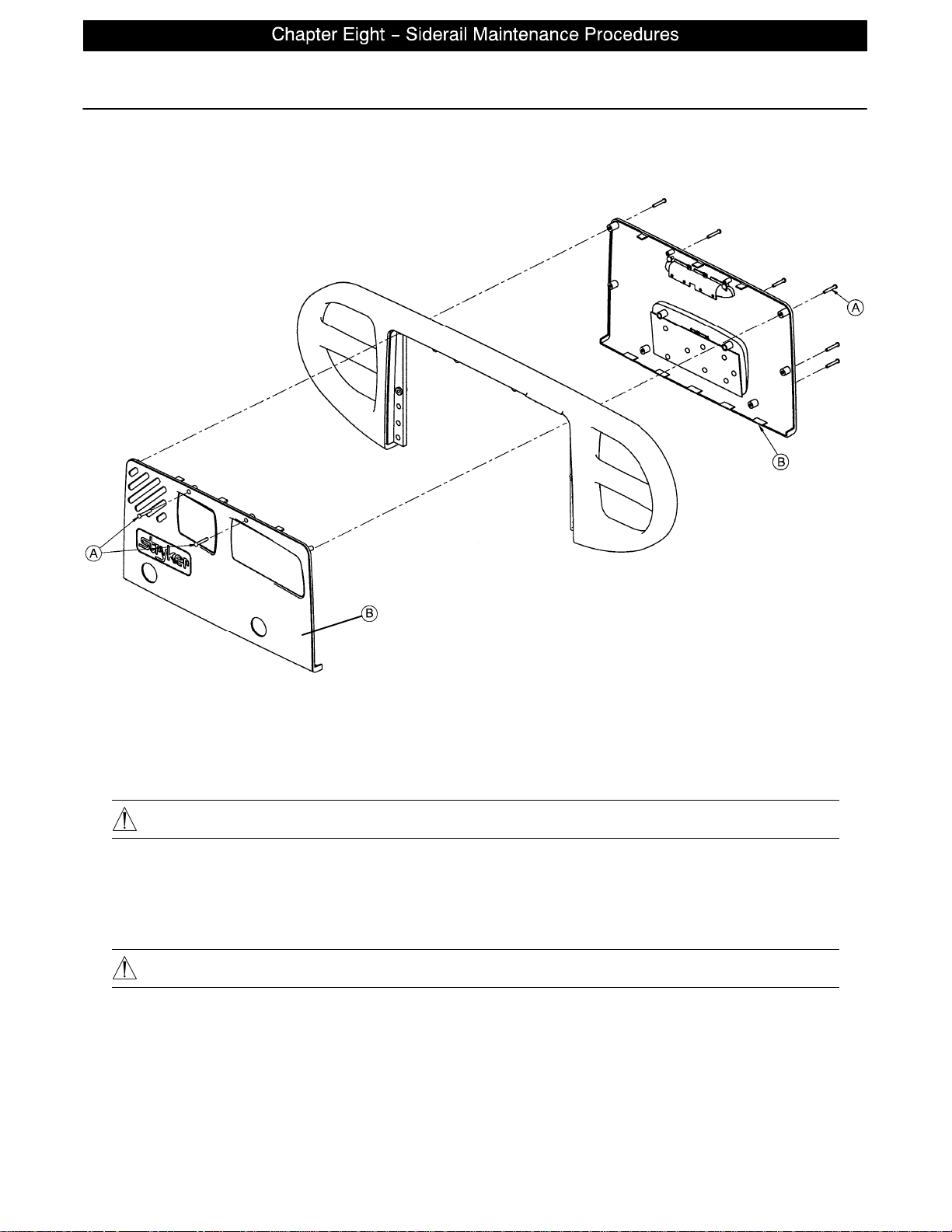
Head and Foot Siderail Cover Removal
Required Tools:
#2 Phillips Screwdriver
Removal Procedure:
1. Unplug the power cord from the wall receptacle.
2. Using a #2 Phillips screwdriver, remove the 8 phillips screws (A) holding the covers (B) to the siderail.
CAUTION
There are two cables connecting the outside cover to the head end siderail. Be careful not to pull on them
when removing the cover.
3. Remove the cables from the siderail. Make note of the proper location for the cables.
4. Reverse the above steps to reattach the cover.
CAUTION
Do not snag the cables when installing the siderail cover.
NOTE
Follow the same procedure for siderail cover removal for the foot end rails.
page 8−2
Page 50
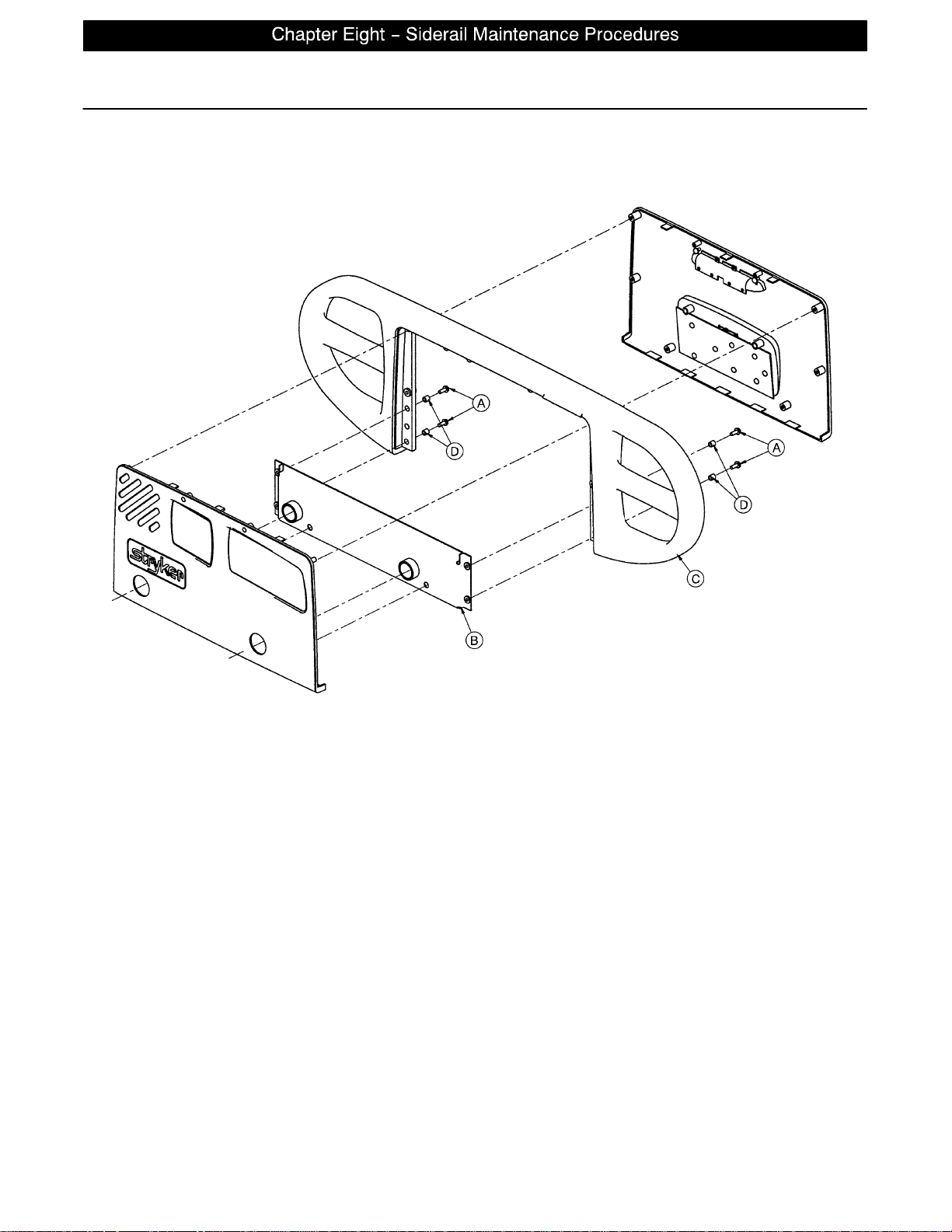
Head and Foot Molded Siderail Replacement
Required Tools:
#2 Phillips Screwdriver 3/8” Nut Driver
Procedure:
1. Unplug the bed power cord from the wall socket.
2. Remove the siderail cover (see page 8−2).
3. Using a 3/8” nut driver, remove the four screws (A) holding the molded rail (C) to the siderail support
assembly (B).
NOTE
Note the location of the spacers (D) for re−assembly purposes.
4. Pull up on the molded rail (C) to remove it from the siderail assembly.
5. Reverse the above steps to install the new molded rail.
page 8−3
Page 51
Head End Siderail Cable Replacement
Required Tools:
#2 Phillips Screwdriver Side Cutters
Procedure:
1. Run the head section fully up.
2. Unplug the bed power cord from the wall socket.
3. Using a #2 Phillips screwdriver, remove the eight screws holding the siderail cover and remove the cover.
4. Put the siderail in the down position.
5. Using a #2 Phillips screwdriver, remove the two screws (E) holding the rear siderail pivot arm cover to
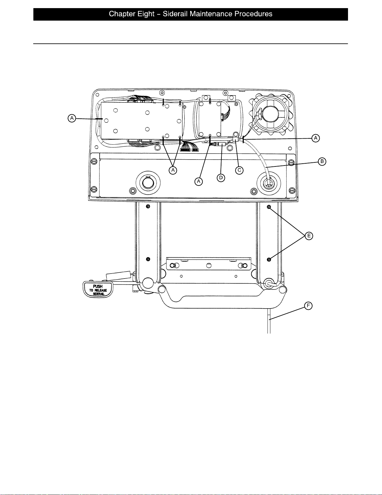
the pivot arm. Remove the cover to expose the siderail cables.
page 8−4
Page 52

Head End Siderail Cable Replacement (Continued)
6. Using side cutters, clip the cable ties (A) holding the cables together.
7. Using a #2 Phillips screwdriver, remove the cable clamp (C) from the siderail.
8. Disconnect cable (B) from the circuit board and cable (D) from the speaker.
NOTE
The speaker and nurse call are optional equipment and may not be in the siderail as shown.
9. Pull the cables through the siderail (toward the center of the bed).
10. Unplug the cable assembly (F) underneath the head section.
11. Reverse the above steps to install the new cable.
CAUTION
Be sure to position the cables on both sides of the pivot arm, as shown in the illustration on page 8−4, before
reattaching the pivot arm cover. If not done properly, the cover will not fit tightly and damage could occur to
the cables.
page 8−5
Page 53

Notes
page 8−6
Page 54

GENERAL INFORMATION
This section contains tool lists and step−by−step procedures to assist with the maintenance and servicing
of the foot board portion of your equipment.
FOOT BOARD MAINTENANCE CONTENTS
Foot Board Hinge Removal 9−2. . . . . . . . . . . . . . . . . . . . . . . . . . . . . . . . . . . . . . . . . . . . . . . . . . . . . . . . . . . . . .
Foot Board Module Replacement 9−3. . . . . . . . . . . . . . . . . . . . . . . . . . . . . . . . . . . . . . . . . . . . . . . . . . . . . . . . .
Foot Board Interface Plug Replacement 9−4. . . . . . . . . . . . . . . . . . . . . . . . . . . . . . . . . . . . . . . . . . . . . . . . . . .
page 9−1
Page 55
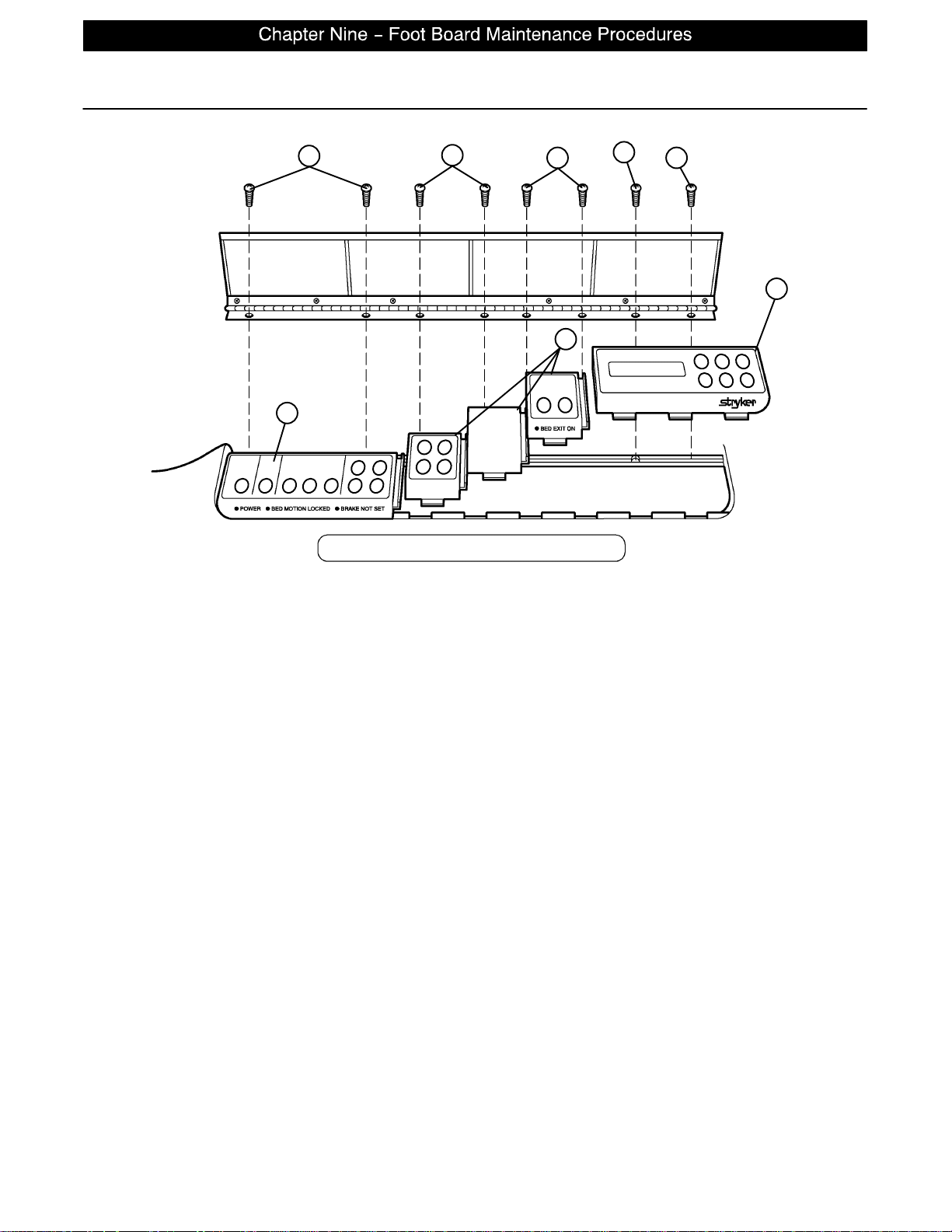
Foot Board Hinge Removal
A
C
A
A
C
B
A
C
Required Tools:
#2 Phillips Screwdriver
Procedure:
1. Using a #2 Phillips screwdriver, remove the screws (A & B) holding the door and hinge assembly to the
foot board.
2. If replacing the hinge only, use a Phillips screwdriver to remove the screws holding the hinge to the door.
3. Reverse the above steps to attach the replacement door and/or hinge.
NOTE
Screw (B) is a machine screw and must be reinstalled in the proper hole.
page 9−2
Page 56
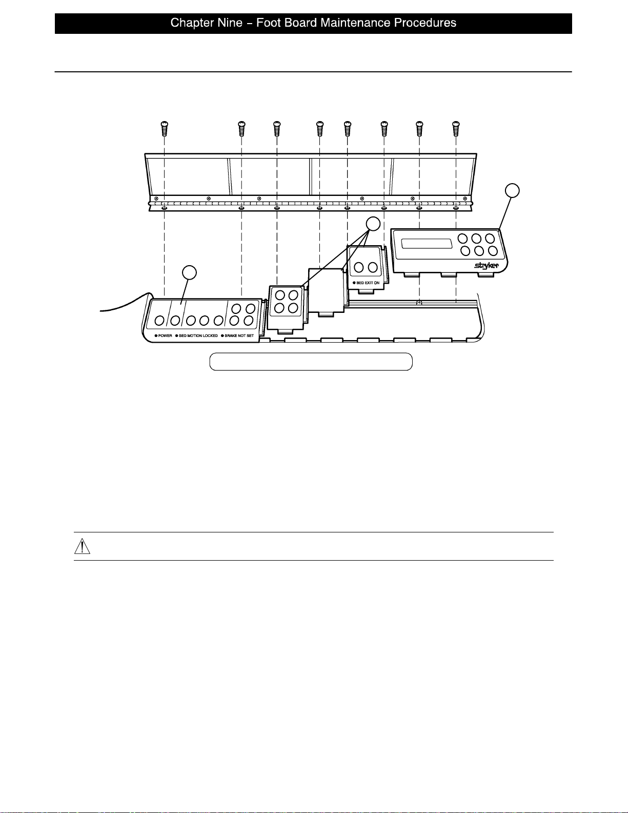
Foot Board Module Replacement
A
A
A
Required Tools:
#2 Phillips Screwdriver
Procedure:
1. Unplug the bed power cord from the wall socket. Remove the foot board hinge (see above).
NOTE
Regardless of which module is being replaced, the farthest module to the right must be removed first.
2. Pull the module out of the foot board and disconnect the cable from the module (A).
3. Reverse the above steps to install the new module.
CAUTION
The modules must be overlapped as shown in the illustration to prevent fluids from entering the board cavity
and causing damage.
page 9−3
Page 57
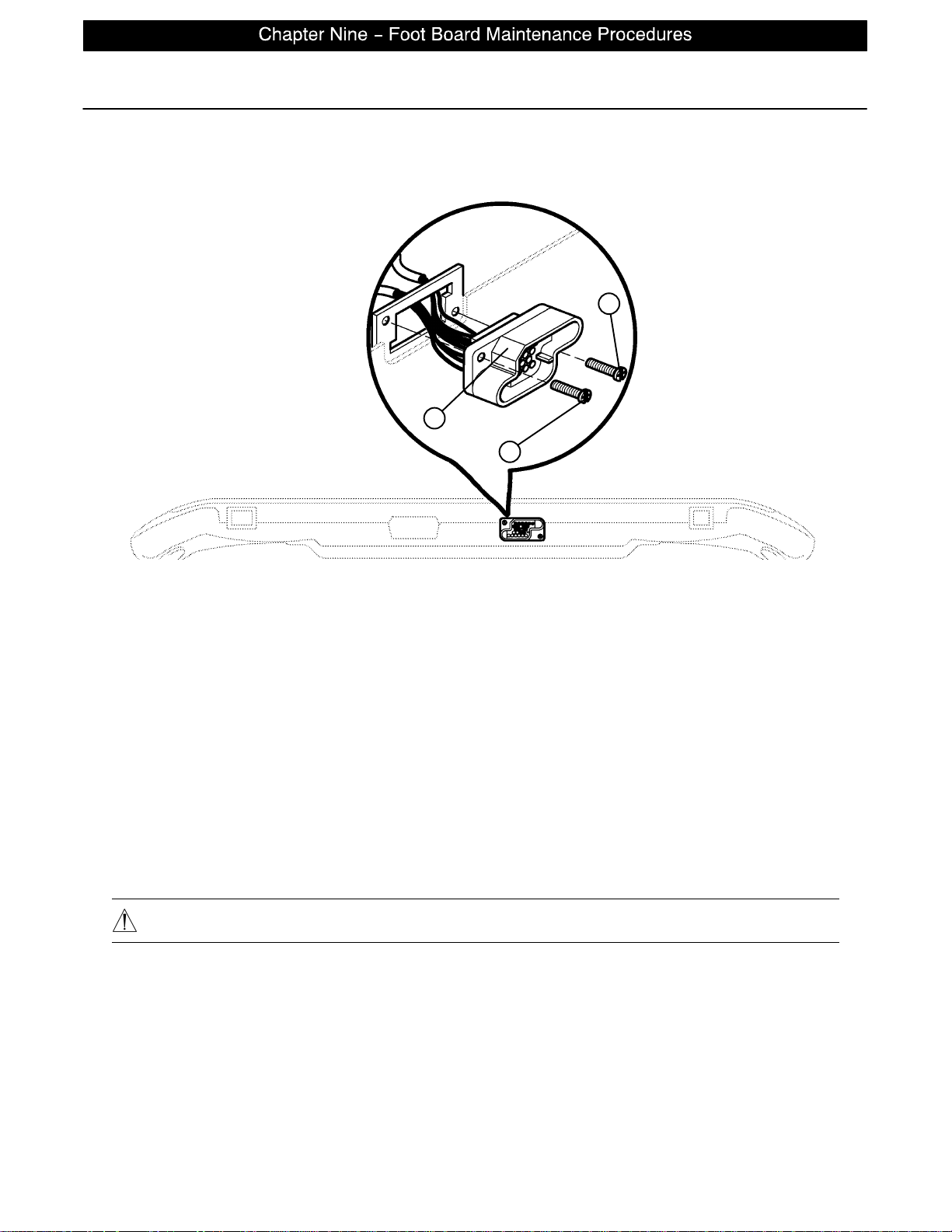
Foot Board Interface Plug Replacement
Required Tools:
#2 Phillips Screwdriver
A
B
A
BOTTOM VIEW OF FOOT BOARD
Procedure:
1. Unplug the bed power cord from the wall socket.
2. Remove the foot board from the bed to access the bottom of the board.
3. Properly ground yourself (see page 6−2 for static discharge precautions).
4. Using a #2 Phillips screwdriver, remove the eight screws holding the foot board door to the foot board
and remove the door.
5. Using a #2 Phillips screwdriver, remove the two screws (A) holding the plug to the foot board.
6. Disconnect the cable from the foot board module cable. Note proper placement of the cable so it will be
reconnected properly.
7. Reverse the above steps to install the new interface plug.
CAUTION
Be sure to install the plug with the flat edge (B) at the top left, as shown in the illustration, or the foot board
interface plug will not mate properly with the bed and damage to the plug or foot board could result.
page 9−4
Page 58

GENERAL INFORMATION
This section contains assembly drawings and parts lists to assist with the identification of individual components of the equipment and accessories.
In the parts lists, the words “right” and “left” refer to the right and left sides of a patient lying face up on the
bed.
ASSEMBLY DRAWINGS AND PARTS LISTS CONTENTS
Base Assembly 10−3 − 10−9. . . . . . . . . . . . . . . . . . . . . . . . . . . . . . . . . . . . . . . . . . . . . . . . . . . . . . . . . . . . . . . .
Lift Assembly 10−10 − 10−13. . . . . . . . . . . . . . . . . . . . . . . . . . . . . . . . . . . . . . . . . . . . . . . . . . . . . . . . . . . . . . . .
Isolation Plate Assembly 10−14. . . . . . . . . . . . . . . . . . . . . . . . . . . . . . . . . . . . . . . . . . . . . . . . . . . . . . . . . . . . . .
Brake Shaft Assembly 10−15. . . . . . . . . . . . . . . . . . . . . . . . . . . . . . . . . . . . . . . . . . . . . . . . . . . . . . . . . . . . . . . .
Brake Crank Assembly 10−16. . . . . . . . . . . . . . . . . . . . . . . . . . . . . . . . . . . . . . . . . . . . . . . . . . . . . . . . . . . . . . . .
Brake Bar Assembly 10−17. . . . . . . . . . . . . . . . . . . . . . . . . . . . . . . . . . . . . . . . . . . . . . . . . . . . . . . . . . . . . . . . . .
8” Caster Assembly 10−18. . . . . . . . . . . . . . . . . . . . . . . . . . . . . . . . . . . . . . . . . . . . . . . . . . . . . . . . . . . . . . . . . .
8” Steer Caster Assembly 10−19. . . . . . . . . . . . . . . . . . . . . . . . . . . . . . . . . . . . . . . . . . . . . . . . . . . . . . . . . . . . .
8” Wheel Assembly 10−20. . . . . . . . . . . . . . . . . . . . . . . . . . . . . . . . . . . . . . . . . . . . . . . . . . . . . . . . . . . . . . . . . . .
Bottom Cover Assembly 10−21. . . . . . . . . . . . . . . . . . . . . . . . . . . . . . . . . . . . . . . . . . . . . . . . . . . . . . . . . . . . . .
Litter Assembly 10−22 − 10−34. . . . . . . . . . . . . . . . . . . . . . . . . . . . . . . . . . . . . . . . . . . . . . . . . . . . . . . . . . . . . .
Actuator Box Cover Assembly 10−35. . . . . . . . . . . . . . . . . . . . . . . . . . . . . . . . . . . . . . . . . . . . . . . . . . . . . . . . .
Fowler Brake Kit Assembly 10−36. . . . . . . . . . . . . . . . . . . . . . . . . . . . . . . . . . . . . . . . . . . . . . . . . . . . . . . . . . . .
Head End Siderail Assembly 10−37 − 10−43. . . . . . . . . . . . . . . . . . . . . . . . . . . . . . . . . . . . . . . . . . . . . . . . . . .
Siderail Release Lever Assembly 10−44, 10−45. . . . . . . . . . . . . . . . . . . . . . . . . . . . . . . . . . . . . . . . . . . . . . . .
Siderail Latch Assembly 10−46, 10−47. . . . . . . . . . . . . . . . . . . . . . . . . . . . . . . . . . . . . . . . . . . . . . . . . . . . . . . .
Siderail Bypass Detent Clip Assembly 10−48. . . . . . . . . . . . . . . . . . . . . . . . . . . . . . . . . . . . . . . . . . . . . . . . . . .
Head End Siderail Outer Panel Assembly 10−49. . . . . . . . . . . . . . . . . . . . . . . . . . . . . . . . . . . . . . . . . . . . . . . .
Head End Siderail Inner Panel Assembly 10−50. . . . . . . . . . . . . . . . . . . . . . . . . . . . . . . . . . . . . . . . . . . . . . . .
Foot End Siderail Assembly 10−51 − 10−55. . . . . . . . . . . . . . . . . . . . . . . . . . . . . . . . . . . . . . . . . . . . . . . . . . .
page 10 −1
Page 59

ASSEMBLY DRAWINGS AND PARTS LISTS CONTENTS (CONTINUED)
Head Board Assembly 10−56. . . . . . . . . . . . . . . . . . . . . . . . . . . . . . . . . . . . . . . . . . . . . . . . . . . . . . . . . . . . . . . .
Foot Board Assembly 10−57. . . . . . . . . . . . . . . . . . . . . . . . . . . . . . . . . . . . . . . . . . . . . . . . . . . . . . . . . . . . . . . . .
Foot Board Bed Exit Module Assembly 10−58. . . . . . . . . . . . . . . . . . . . . . . . . . . . . . . . . . . . . . . . . . . . . . . . . .
KCI Foot Board Module Assembly 10−59. . . . . . . . . . . . . . . . . . . . . . . . . . . . . . . . . . . . . . . . . . . . . . . . . . . . . .
Foot Board Main Module Assembly 10−60. . . . . . . . . . . . . . . . . . . . . . . . . . . . . . . . . . . . . . . . . . . . . . . . . . . . .
Foot Board Scale Module Assembly 10−61. . . . . . . . . . . . . . . . . . . . . . . . . . . . . . . . . . . . . . . . . . . . . . . . . . . .
2−Stage I.V. Mounting Assembly, Head End 10−62. . . . . . . . . . . . . . . . . . . . . . . . . . . . . . . . . . . . . . . . . . . . .
2−Stage I.V. Pole Assembly 10−63. . . . . . . . . . . . . . . . . . . . . . . . . . . . . . . . . . . . . . . . . . . . . . . . . . . . . . . . . . .
I.V. Pole Latch Assembly 10−64. . . . . . . . . . . . . . . . . . . . . . . . . . . . . . . . . . . . . . . . . . . . . . . . . . . . . . . . . . . . . .
Defibrillator Tray Assembly 10−65. . . . . . . . . . . . . . . . . . . . . . . . . . . . . . . . . . . . . . . . . . . . . . . . . . . . . . . . . . . .
page 10 −2
Page 60
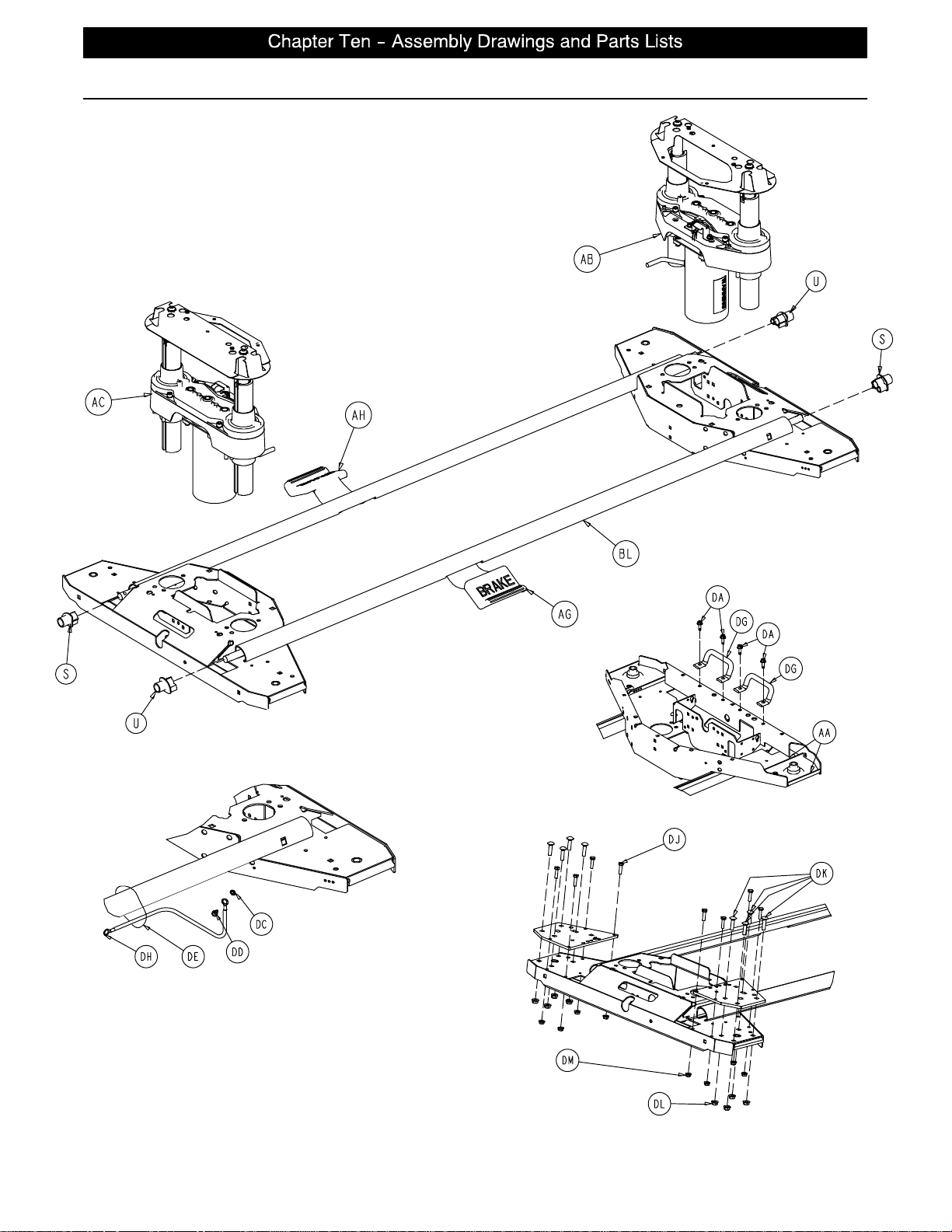
Base Assembly and Options
HEAD END
HEAD END, LEFT
page 10 −3
Page 61
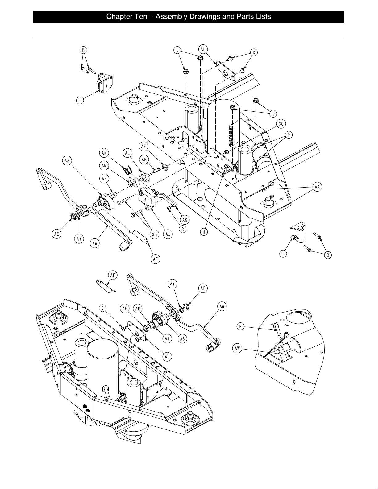
Base Assembly and Options
page 10 −4
Installation of Roll Pin
into Brake Shaft Crank
Typical 4 Places
Page 62
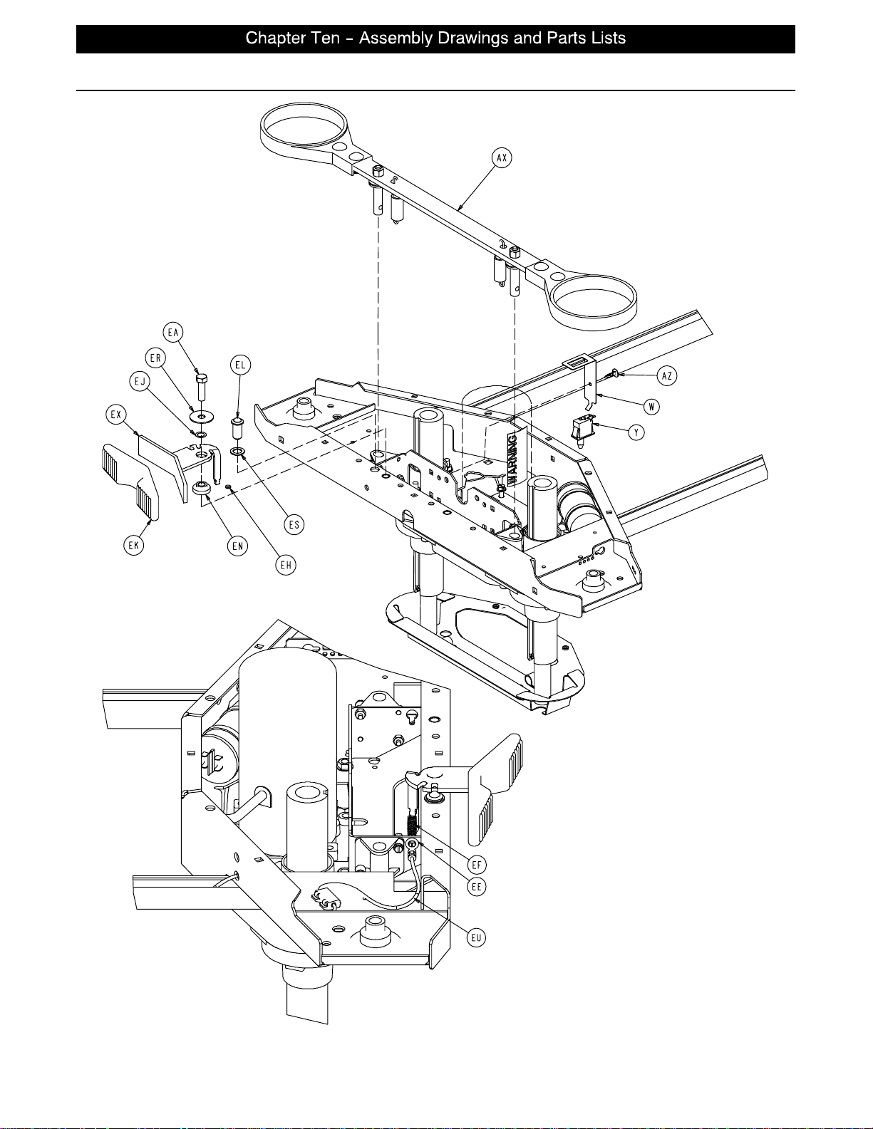
Base Assembly and Options
HEAD END
HEAD END
page 10 −5
Page 63
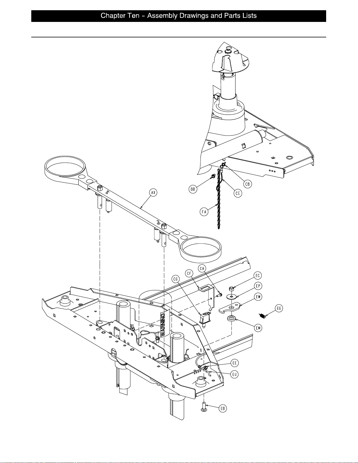
Base Assembly and Options
FOOT END
HEAD END LEFT SIDE
page 10 −6
Page 64
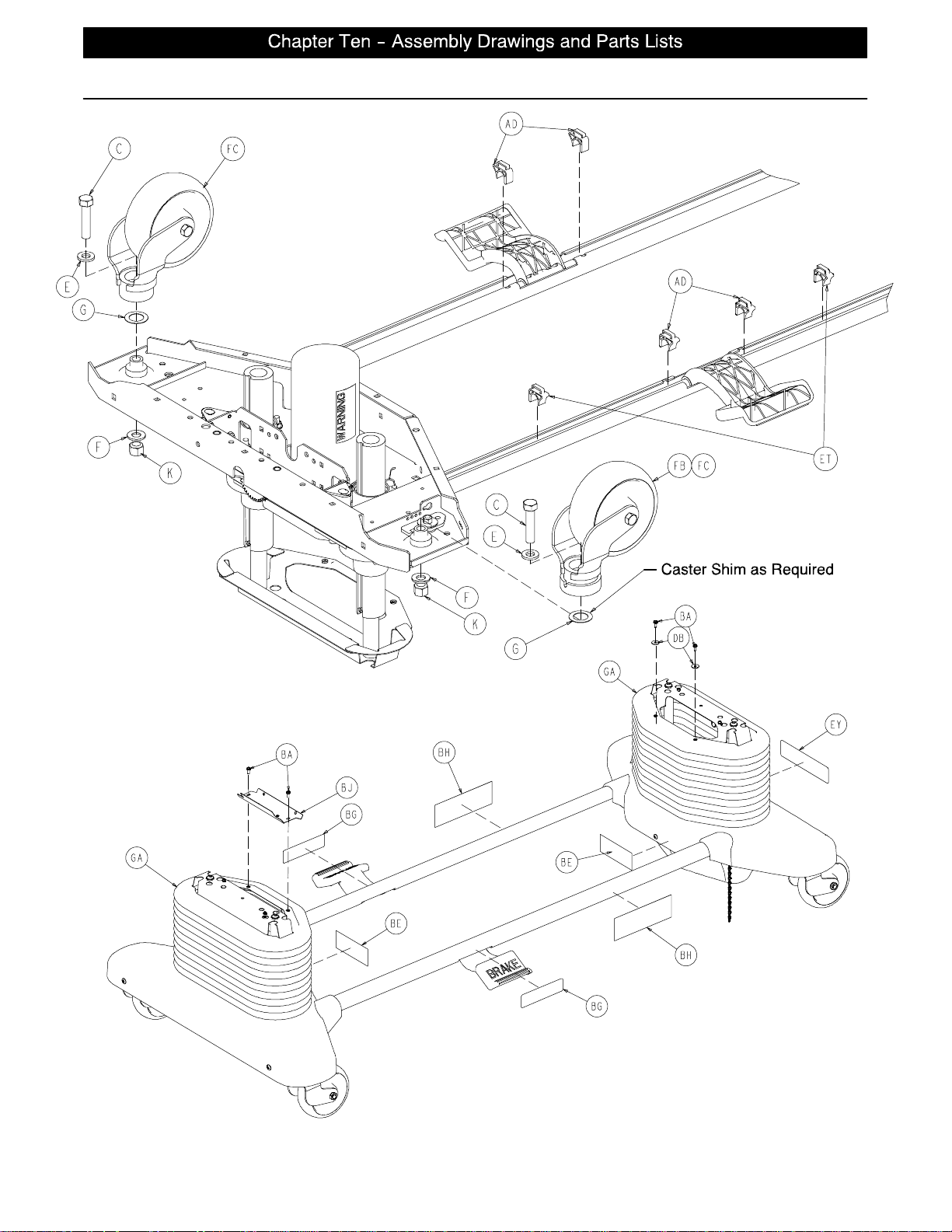
Base Assembly and Options
Steer Option
page 10 −7
Page 65
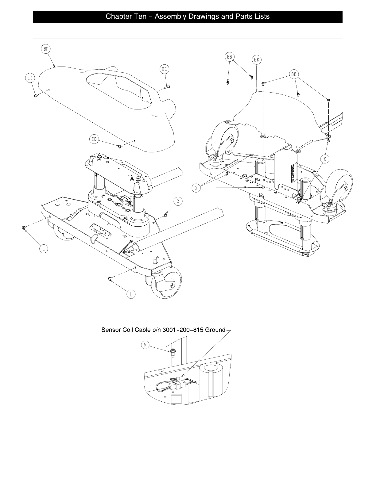
Base Assembly and Options
Typical Both Ends
Typical Both Ends
page 10 −8
Page 66

Base Assembly and Options
Base Assembly Common Components − Part Number 3002−200−3 (Reference Only)
Item Part No. Part Name Qty. Item Part No. Part Name Qty.
B3−122 Hex Washer Hd. Screw 8 AD 3001−200−306 Brake Pedal Shaft Bearing4
D7−52 Truss Hd. Torx 4 AE 3001−200−317 Brake Cam Shaft Bushing 4
E11−310 Washer 4 AF 3001−200−334 Brake Return Ext. Spring 2
G11−343 Washer 4 AG (page 10−15) Brake Shaft Ass’y, Left 1
H16−2 Nylock Nut 8 AH (page 10−15) Brake Shaft Ass’y, Right 1
J16−98 Hex Flange Nut 8 AJ 3002−201−301 Brake Ratchet Track 1
K16−49 Nylock Nut 4 AK 3002−200−302 Brake Ratchet Link Ass’y1
L18−36 Plastic Clip Nut 4 AL 3002−200−305 Brake Ratchet Crank, Lt. 1
M3−224 Hex Washer Hd. Screw 2 AM 3002−200−306 Brake Ratchet Crank, Rt. 1
N26−14 Roll Pin 4 AN 3002−200−307 Brake Latch Spring 1
P38−151 Cable Tie 4 AP 3002−200−318 Brake Ratchet Crank Pin 1
R 3002−200−316 Brake Track Roller 1 AR 3002−200−311 Brake Shaft 2
S 3000−200−305 Brake Shaft Bushing, Rt. 2 AS 3002−201−312 Brake Cam 2
T 3000−200−328 Brake Guide Bushing 4 AT 3002−200−313 Brake Cam Spacer 1
U 3000−200−331 Brake Shaft Bushing, Lt. 2 AU 3002−200−314 Brake Mounting Bracket 2
W 3000−200−343 Brake Switch Bracket 1 AW (page 10−16) Brake Crank Assembly 2
X 3000−300−2 Plastic Clip Nut 10 AX (page 10−17) Brake Bar Assembly 2
Y 3000−300−58 Plunger Switch 1 AY 3000−200−349 Special Narrow Washer 2
Z 3000−300−113 8” Cable Tie 6 AZ 3000−300−115 Stand−Off 1
AB (page 10−10) Head End Lift Assembly 1 GB 3−74 Hex Hd. Bolt 2
AC (page 10−10) Foot End Lift Assembly 1 GC 16−28 Nylock Nut 2
Base Assembly, TriaDyne III Bed − Part Number 2033−245−3 (Reference Only)
Item Part No. Part Name Qty. Item Part No. Part Name Qty.
C3−333 Hex Hd. Cap Screw 4 DB 11−156 Flat Washer 2
X 3000−300−2 Plastic Clip Nut 1 DC 13−18 Ext. Tooth Lock Washer 1
AB (page 10−10) Head End Lift Assembly 1 DD 23−25 Hex Washer Hd. Screw 1
AC (page 10−10) Foot End Lift Assembly 1 DE 38−151 Cable Tie 1
BA 3−224 Hex Washer Hd. Screw 4 DG 3001−245−115 Tie Down Bar 4
BB 23−25 Hex Washer Hd. Screw 11 DH 3001−245−801 Ground Jumper 1
BC 23−264 Truss Hd. Screw 1 DJ 3−54 Hex Hd. Cap Screw 16
BD 52−800 Mounting Standoff 1 DK 5−16 Carriage Bolt 15
BE 988−2−708 Caution Label 2 DL 16−98 Hex Flange Nut 15
BF 3002−300−9 Uni−Pan Cover 1 DM 16−315 Hex Flange Nut 16
BJ 3001−200−8 Bellows Bracket 1 DN 3001−245−150 Reinforcement Plate 4
BK 3001−200−22 Bottom Cover 2 DP 2033−200−9 Uni−Pan Cover 1
BL 3002−245−102 Base Weldment 1 GA 2030−000−101 Bellows 2
DA 3−226 Hex Washer Hd. Screw 8
Base Assembly, Steer Option − Part Number 3001−999−137 (Reference Only)
Item Part No. Part Name Qty. Item Part No. Part Name Qty.
EA 3−349 Hex Hd. Cap Screw 1 EM 3000−200−339 Steer Lock Lever Bushing 1
EB 5−16 Carriage Bolt 1 EN 3000−200−341 Steer Pedal Bushing 1
EC 16−11 Nylock Nut 1 EP 3000−200−347 Special Washer 1
ED 23−92 Truss Phillips Hd. Screw 4 ER 3000−200−348 Special Wide Washer 1
EE 30−52 Snap Bushing 2 ES 3000−200−349 Special Narrow Washer 1
EF 38−414 Pedal Extension Spring 1 ET 3001−200−306 Brake Pedal Shaft Brg. 2
EG 38−416 Lever Extension Spring 1 EU 3001−200−342 Steer Cable Assembly 1
EH 45−8O−Ring 1 EW 3001−200−370 Steer Lock Lever 1
EJ 52−305 Brass Flat Washer 1 EX 3001−200−371 Steer Pedal Arm 1
EK 3000−200−336 Steer Pedal 1 EY 5000−90−13 Steer Label 1
EL 3000−200−337 Push Fit Ball Plunger 1
8” Casters − 3001−999−139 (Ref.)
Item Part No. Part Name Qty. Item Part No. Part Name Qty.
FA 3001−200−53 8” Ground Chain 1 FD 2025−1−47 Caster Cover, Right 4
FB (page 10−19) 8” Steer Caster Assembly 1 FE 2025−1−48 Caster Cover, Left 1
FC (page 10−18) 8” Caster Assembly 3
page 10 −9
Page 67
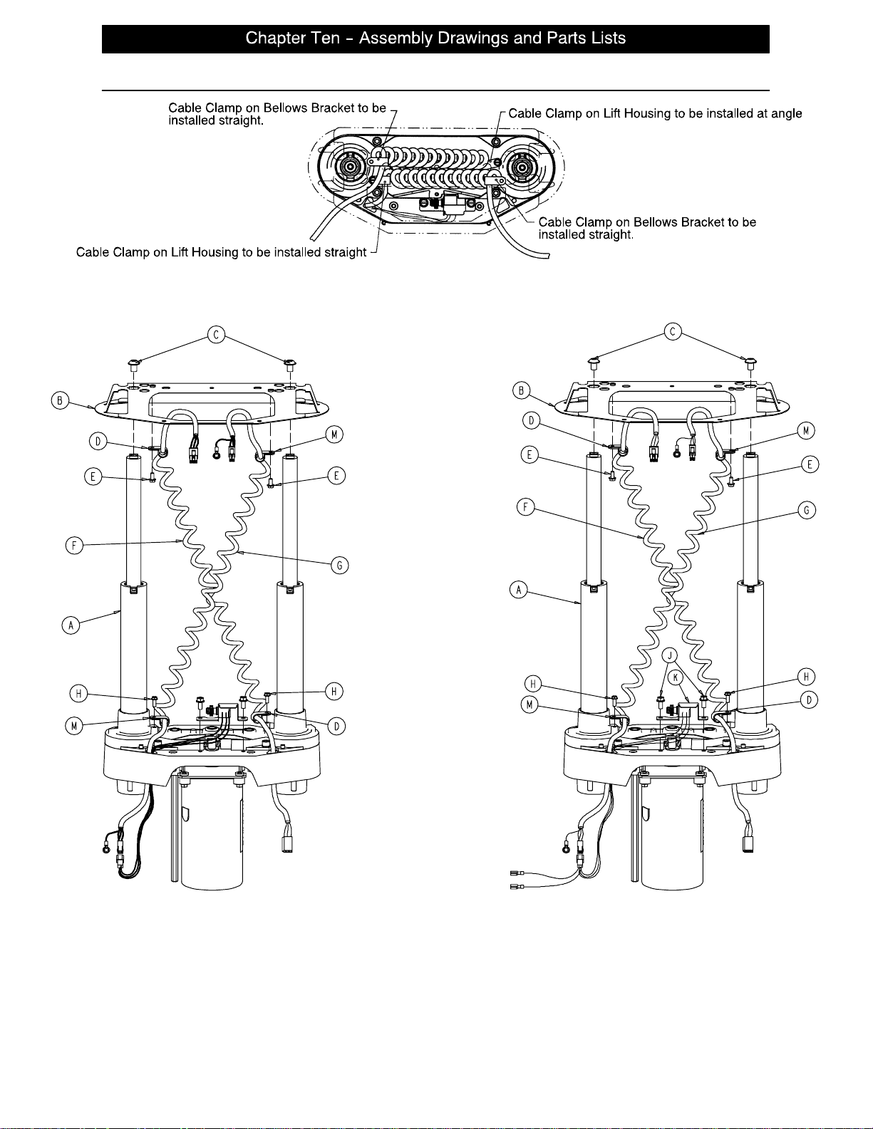
Lift Assembly (Head and Foot End)
Top View
3001−245−200 Head End2033−245−250 Foot End
Item Part No. Part Name Qty. Item Part No. Part Name Qty.
A (page 10−11) Common Lift Assembly 1 H 3−128 Hex Washer Hd. Screw 2
B 2033−200−52 Bellows Bracket 1 J 3−121 Hex Washer Hd. Screw 2
D34−22 Cord Clamp 2 K 3001−200−240 Head End Pot. Ass’y1
E3−106 Hex Washer Hd. Screw 2 3001−200−230 Foot End Pot. Ass’y1
F 3001−200−864 Power Coil Cord 1 M 34−381 Cord Clamp 2
G 3001−200−815 Sensor Coil Cord 1
page 10 −10
Page 68
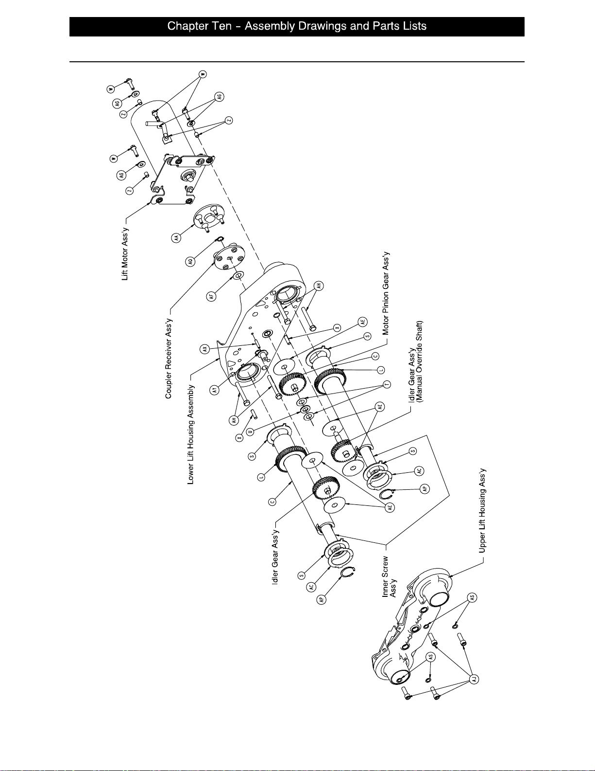
Lift Assembly (Common)
Assembly part number 3001−245−275 (reference only)
page 10 −11
Page 69
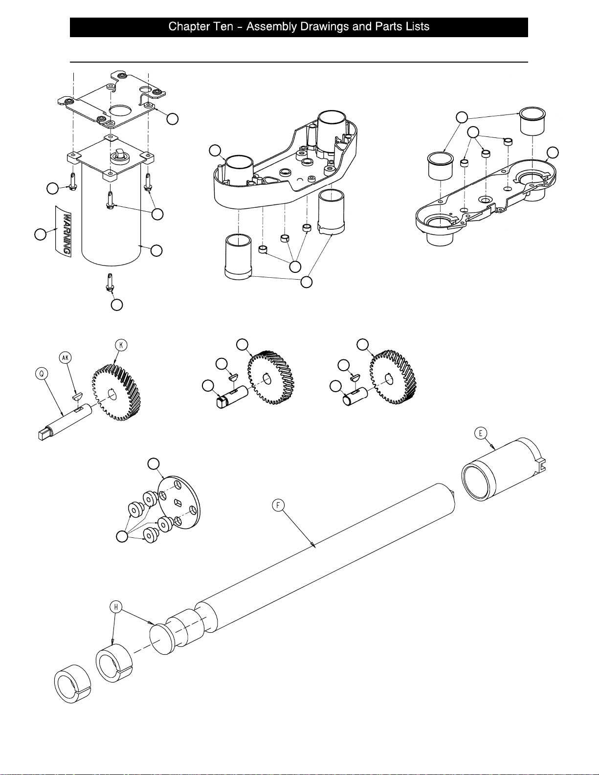
Lift Assembly (Common)
AM
AV
Lift Motor Ass’y
AM
AM
N
M
B
V
G
D
V
A
Upper Lift Housing Ass’y
Lower Lift Housing Ass’y
J
AK
R
K
AK
P
Idler Gear Ass’y
(Manual Override Shaft)
AD
Coupler Receiver Ass’y
Motor Pinion Gear Ass’y Idler Gear Ass’y
AB
Inner Screw Ass’y
page 10 −12
Page 70

Lift Assembly (Common)
Item Part No. Part Name Qty.
A 3000−200−201 Upper Lift Housing 1
B 3000−200−202 Lower Lift Housing 1
C 3000−200−251 Outer Screw 2
D 3000−200−204 Upper Housing Sleeve 2
E 3000−200−205 Upper Stage Nut 2
F 3000−200−249 Inner Screw 2
G 3000−200−207 Lower Stage Nut 2
H 3000−200−208 Glide Bushing 4
J 3000−200−209 Motor Pinion Gear 1
K 3000−200−210 Idler Gear 2
L 3000−200−252 Output Gear 2
M (page 10−14) Motor Isolation Plate Ass’y1
N 3000−200−213 Lift Motor 1
P 3000−200−218 Idler Shaft, Lift 1
Q 3002−200−235 Idler Man. Over. Shaft 1
R 3000−200−220 Input Pinion Shaft 1
S 3000−200−223 Output Gear Thr. Washer 4
T 3000−200−224 Input Gear Thr. Washer 2
U81−212 Thrust Needle Roller Brg. 1
V 3000−200−226 Pinion Shaft Bushing 6
W 3001−200−228 Mounting Standoff 4
X26−231 Dowel Pin 2
Z 3001−300−19 Isolation Sleeve 4
AA 3000−200−233 Lift Motor Coupler 1
AB 3000−200−234 Coupler Receiver 1
AC 3000−200−241 Crush Washer 2
AD 3000−300−455 Isolation Bushing 4
AE 3000−200−245 Gear Washer 5
AF 3000−200−246 Nylon Washer 1
AG 11−408 Flat Washer 4
AH 3−82 Hex Hd. Cap Screw 4
AJ 4−213 Soc. Hd. Cap Screw 4
AK 58−44 Woodruff Key 3
AM 3−331 Hex Washer Hd. Screw 4
AP 28−121 Retaining Ring 2
AQ 28−97 Retaining Ring 1
AS 11−308 Serrated Belleville Washer 4
AV 3000−300−604 Warning Label 1
AX 3000−200−239 Pot. Drive Gear Shaft 1
AY 3000−200−216 Potentiometer Drive Gear 1
page 10 −13
Page 71
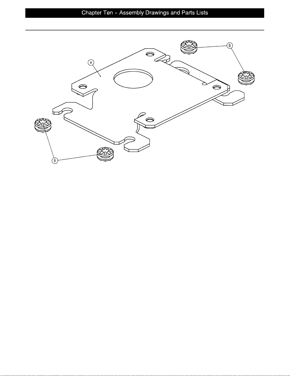
3000−200−723 Isolation Plate Assembly
Assembly part number 3001−200−214 (reference only)
Item Part No. Part Name Qty.
A 3001−200−213 Isolation Plate 1
B 3000−300−442 Grommet 4
page 10 −14
Page 72
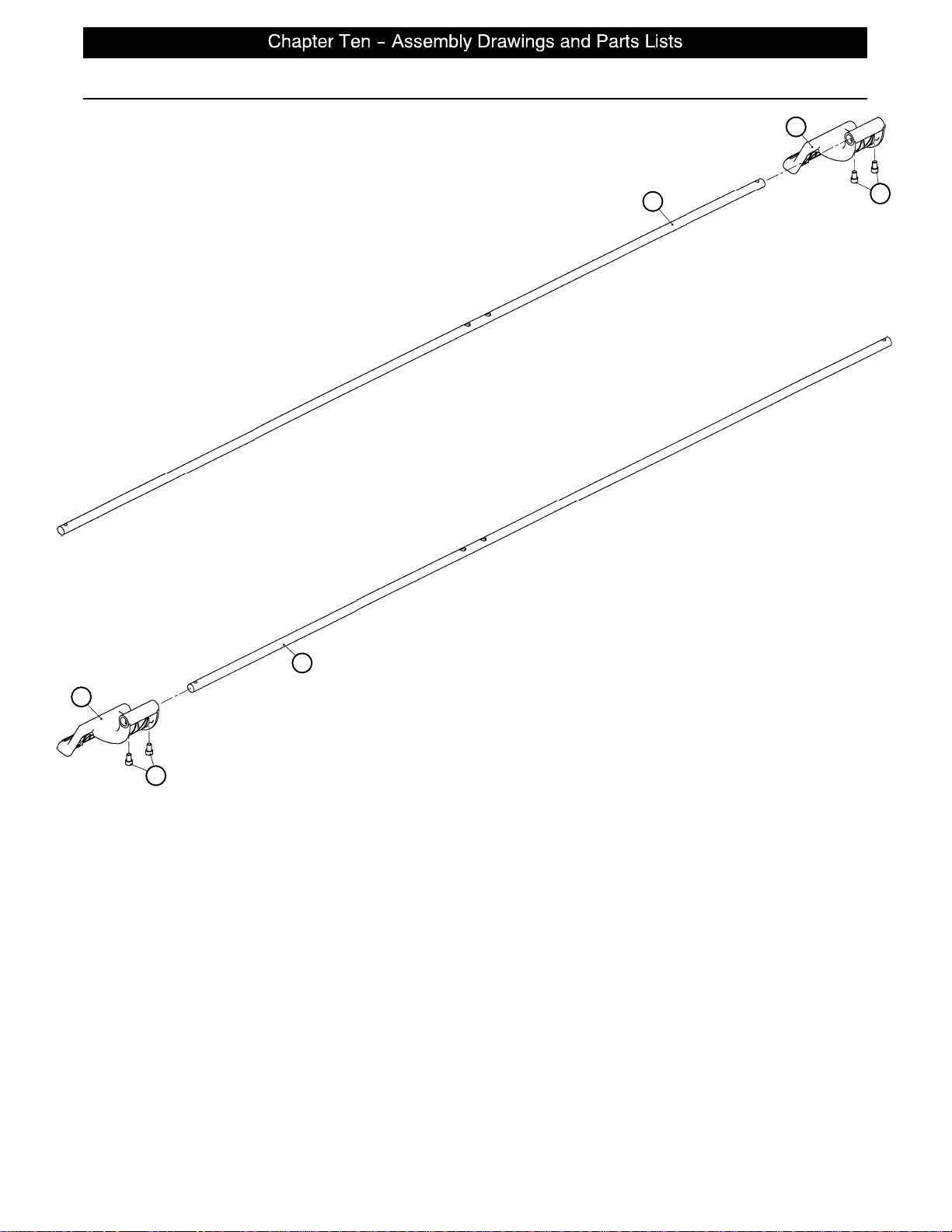
Brake Shaft Assembly, Left and Right
B
Assembly part number 3001−200−340 (Left)
Assembly part number 3001−200−345 (Right)
A
C
A
B
C
Item Part No. Part Name Qty.
A 3000−200−314 Brake Shaft 1
B 3001−200−325 Brake Pedal 1
C4−270 Soc. Hd. Cap Screw 2
page 10 −15
Page 73
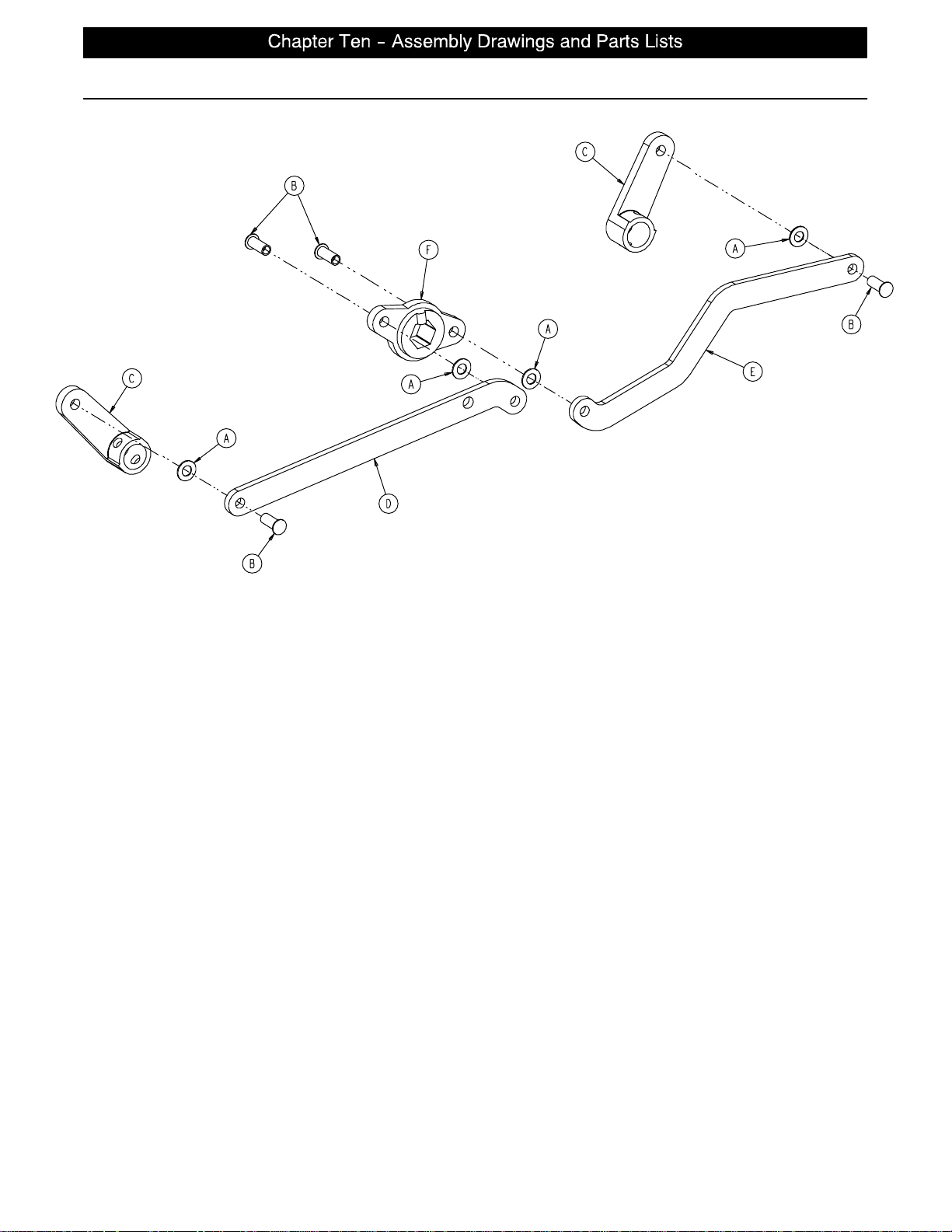
3001−200−330 Brake Crank Assembly
Item Part No. Part Name Qty.
A14−4 Washer 4
B25−146 Semi−Tubular Rivet 4
C 3000−200−302 Brake Shaft Crank 2
D 3001−200−311 Brake Link 1
E 3001−200−312 Dog Leg Brake Link 1
F 3002−200−309 Brake Crank 1
page 10 −16
Page 74
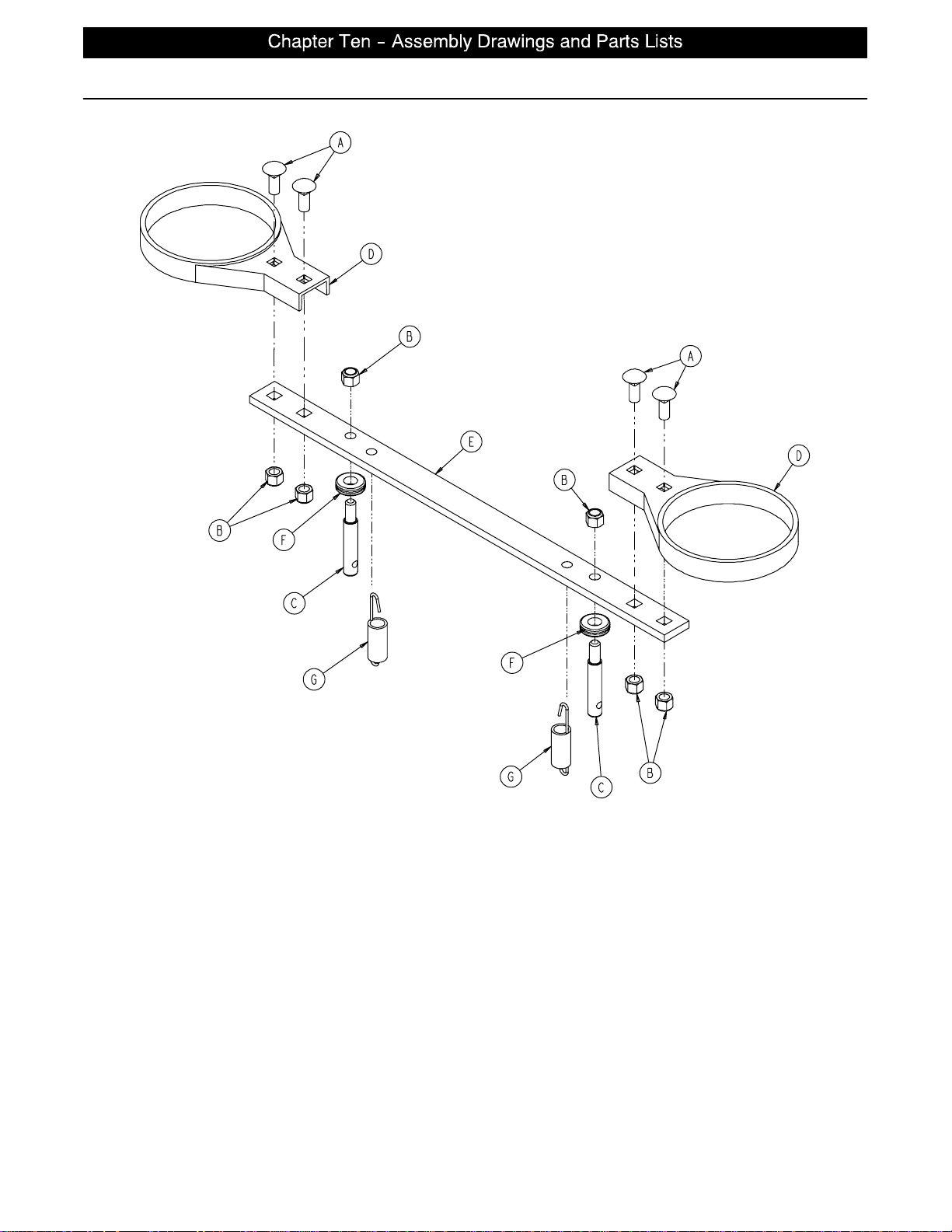
Brake Bar Assembly
Assembly part number 3002−200−335 (reference only)
Item Part No. Part Name Qty.
A5−18 Carriage Bolt 4
B16−35 Nylock Hex Nut 6
C 3000−200−318 Guide Pin 2
D 3000−200−321 Brake Ring 2
E 3000−200−323 Brake Bar 1
F 3000−200−324 Brake Bar Bumper 2
G 3002−200−310 Brake Bar Return Spring 2
page 10 −17
Page 75
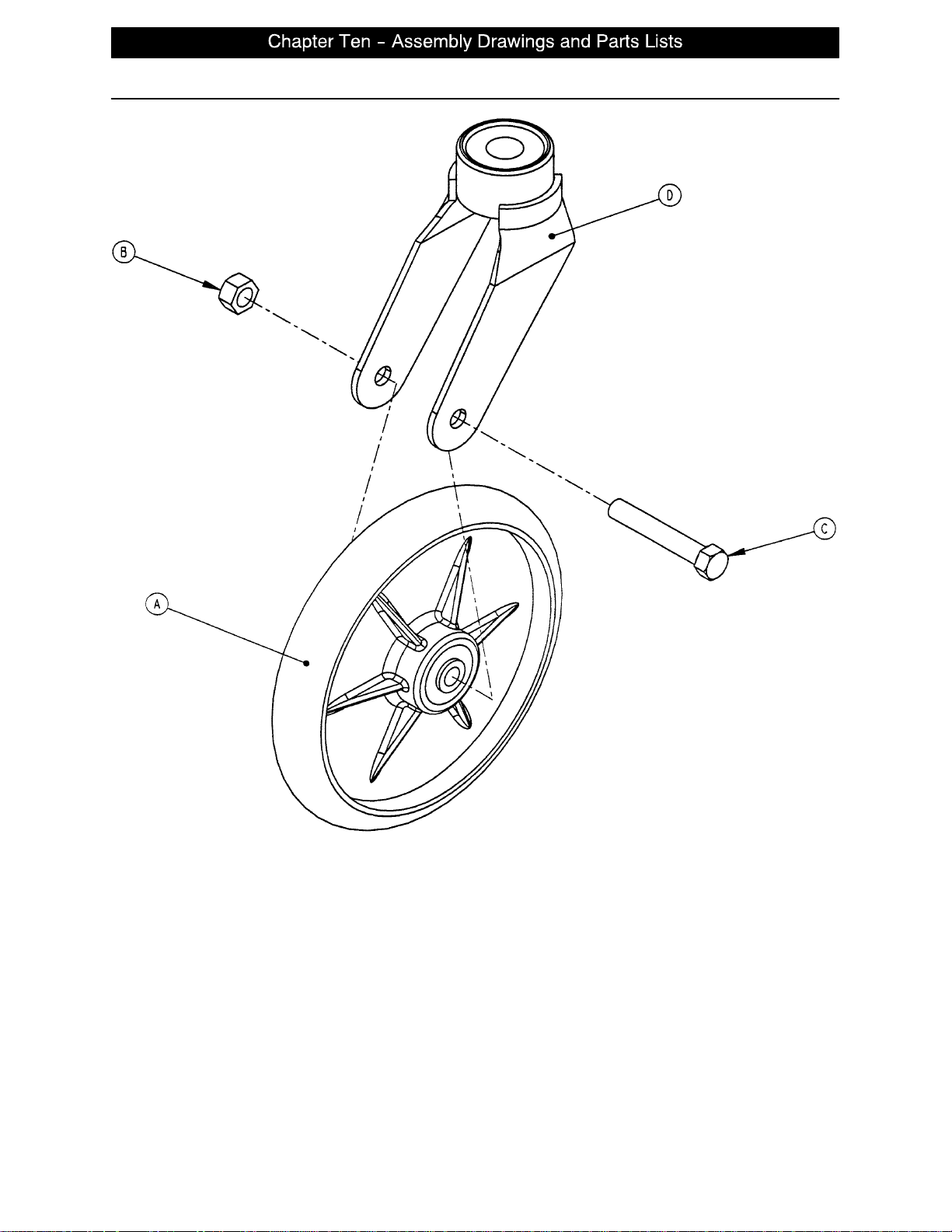
3001−200−90 8” Caster Assembly
Item Part No. Part Name Qty.
A (page 10−20) Wheel Assembly 1
B16−60 Hex Nut 1
C3−99 Hex Hd. Cap Screw 1
D 3001−200−76 Caster Horn 1
NOTE
The hex head cap screw (item C) must be threaded through the caster horn in the direction shown to avoid
damaging the plastic caster covers.
page 10 −18
Page 76
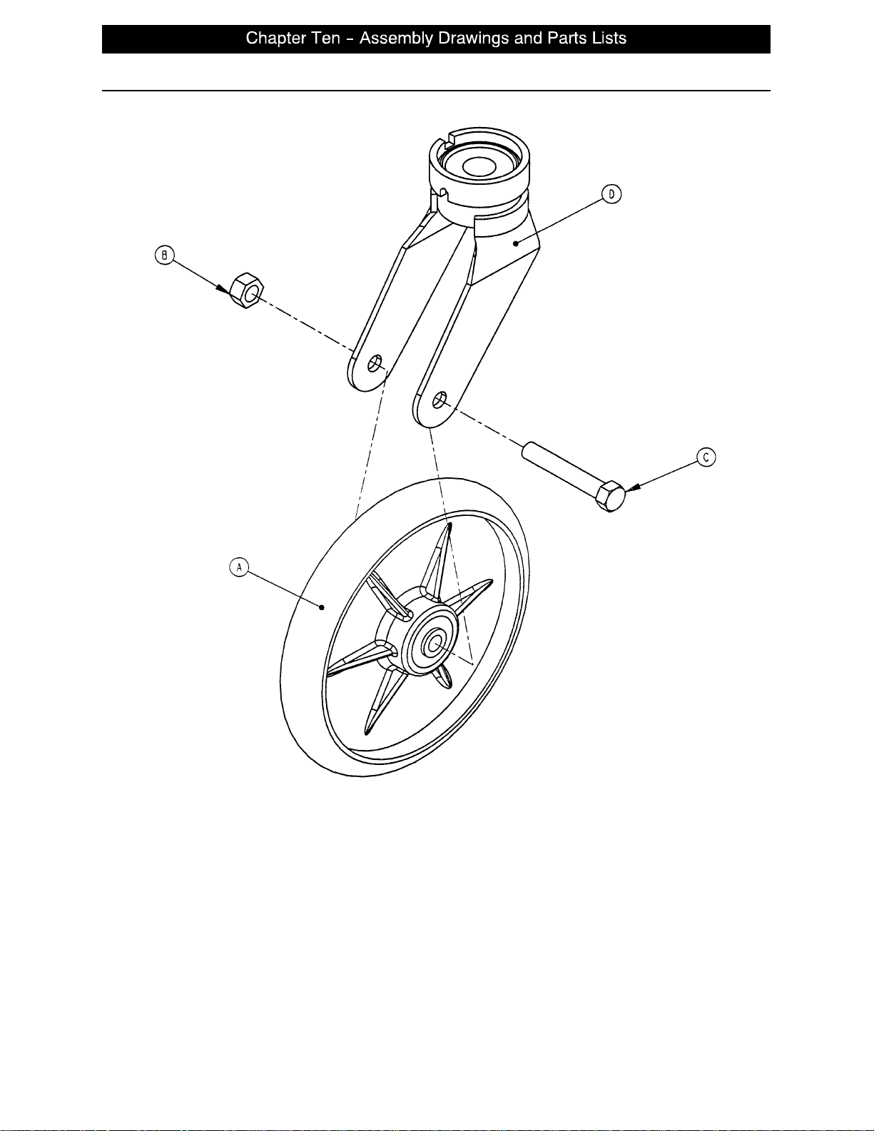
3001−200−80 8” Steer Caster Assembly
Item Part No. Part Name Qty.
A (page 10−20) Wheel Assembly 1
B16−60 Hex Nut 1
C3−99 Hex Hd. Cap Screw 1
D 3001−200−81 Caster Horn 1
NOTE
The hex head cap screw (item C) must be threaded through the caster horn in the direction shown to avoid
damaging the plastic caster covers.
page 10 −19
Page 77
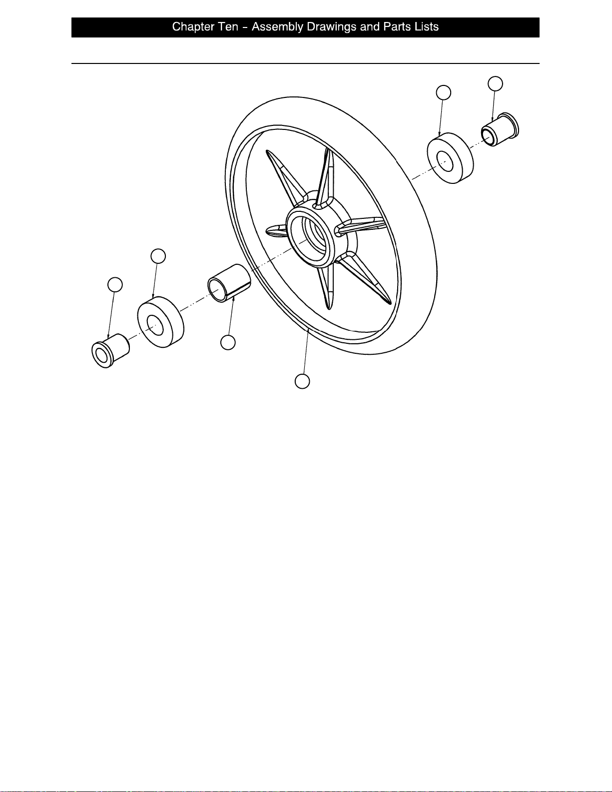
2025−1−49 8” Wheel Assembly
B
B
C
A
C
D
Item Part No. Part Name Qty.
A52−503 Bearing Spacer 1
B81−226 Bearing 2
C 715−1−255 Wheel Bearing 2
D 2025−1−46 Wheel 1
page 10 −20
Page 78
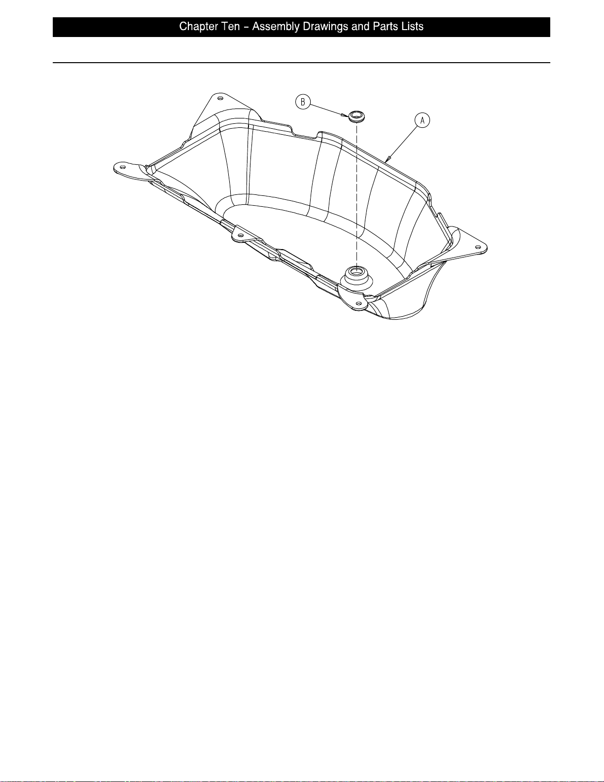
3001−200−22 Bottom Cover Assembly
Item Part No. Part Name Qty.
A 3002−1−100 Bottom Cover 1
B 3000−000−039 Grommet 1
page 10 −21
Page 79
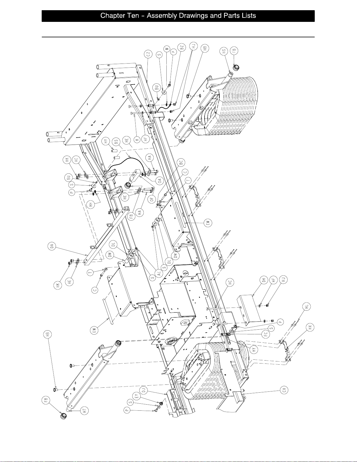
Litter Assembly and Options
page 10 −22
Page 80
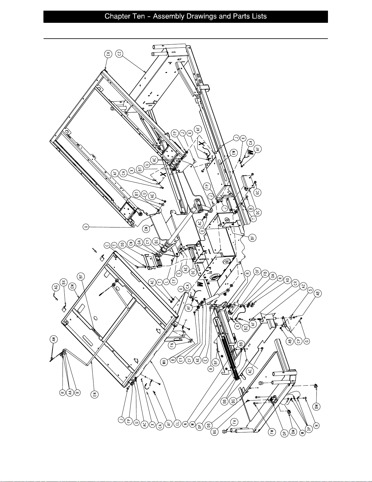
Litter Assembly and Options
page 10 −23
Page 81
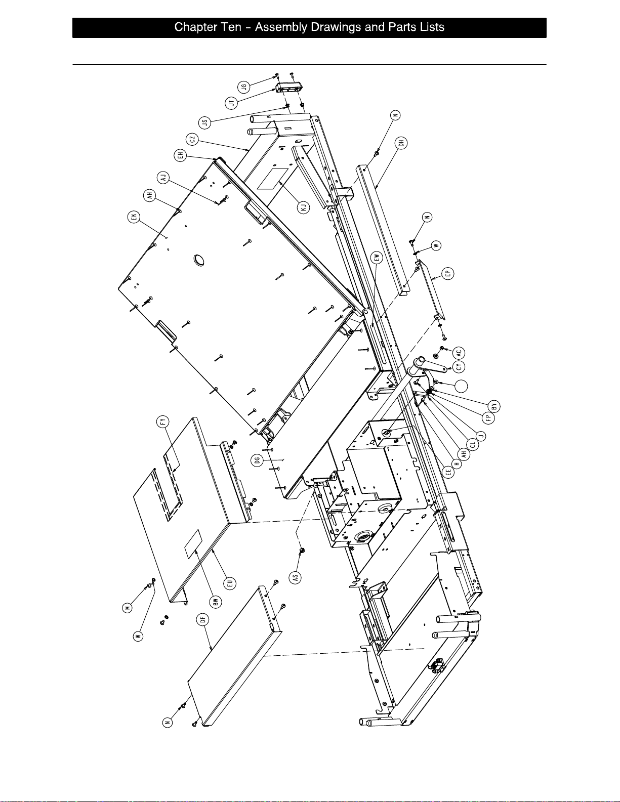
Litter Assembly and Options
GB
page 10 −24
Page 82
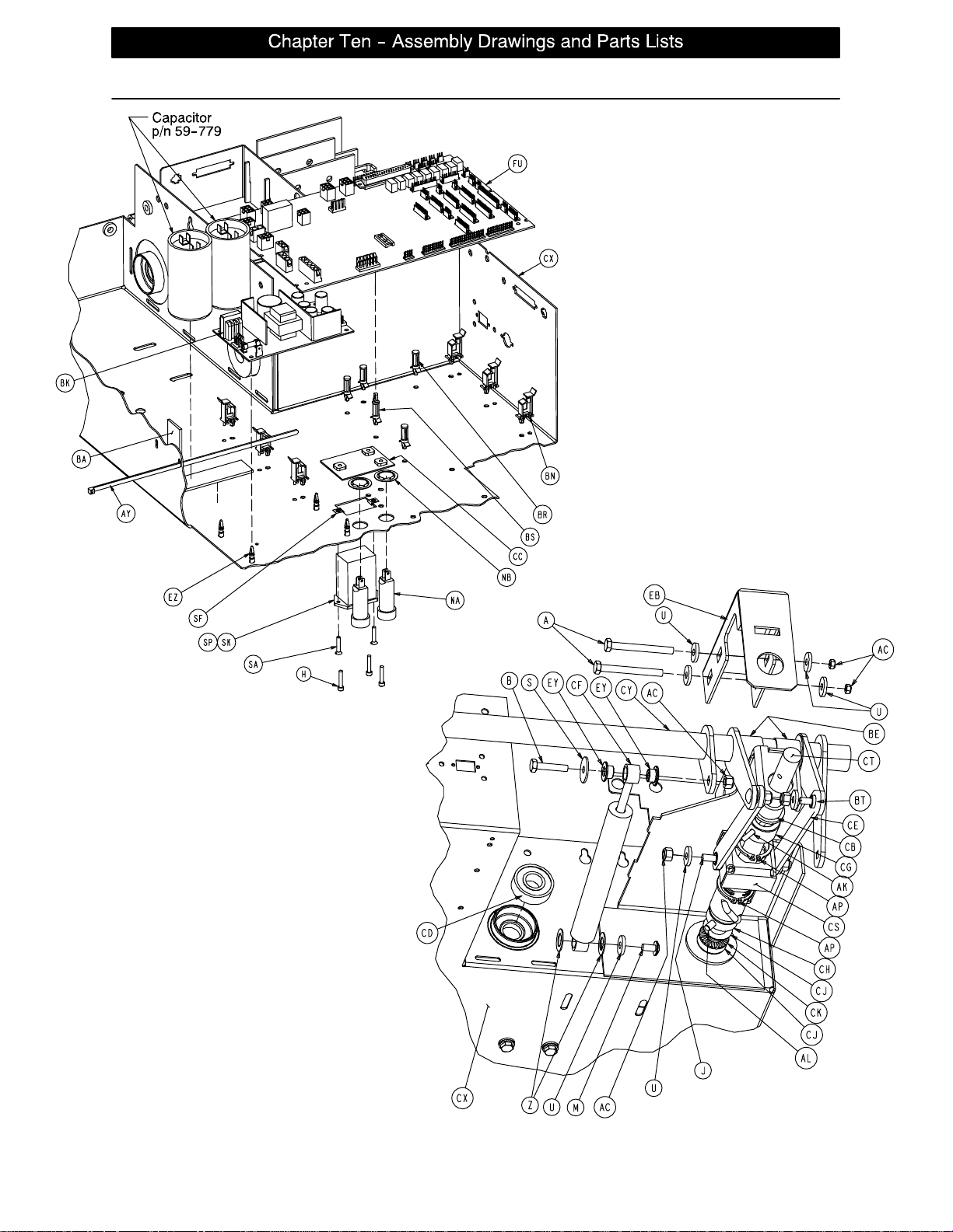
Litter Assembly and Options
page 10 −25
Page 83
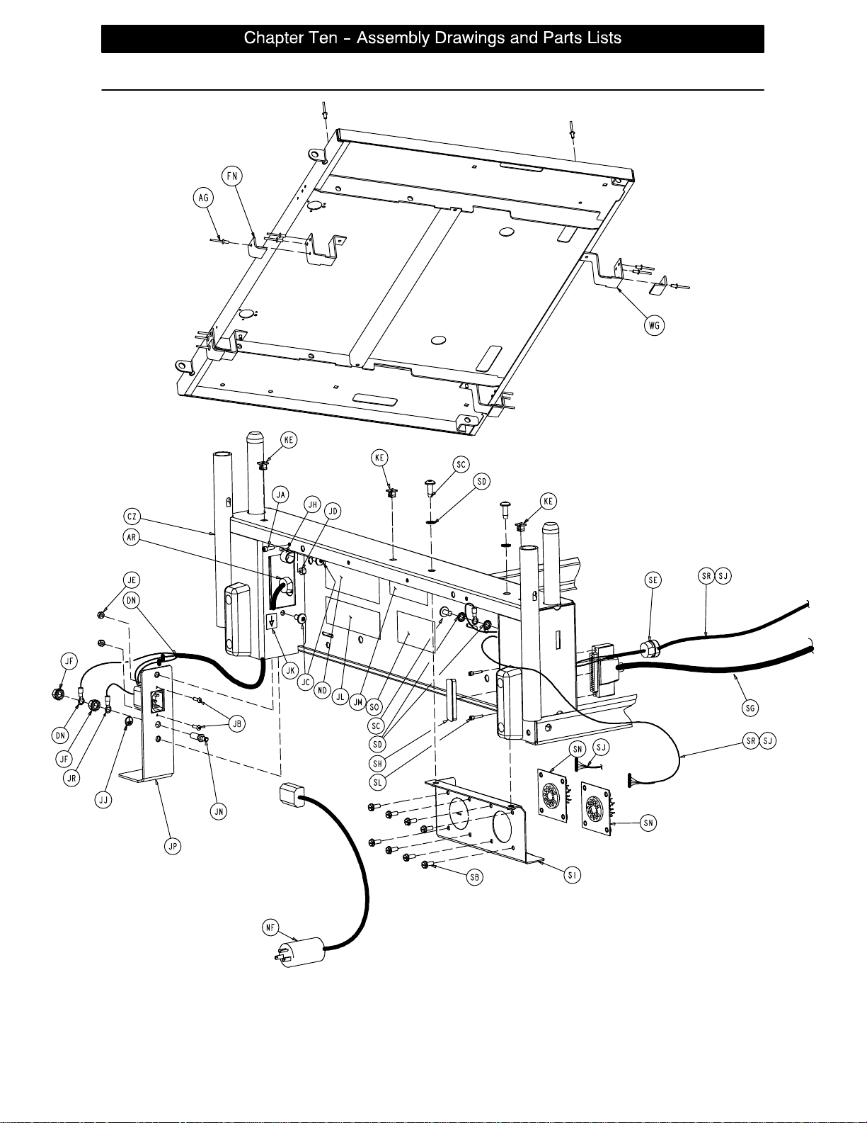
Litter Assembly and Options
FOOT SECTION
page 10 −26
HEAD WALL VIEW
Page 84
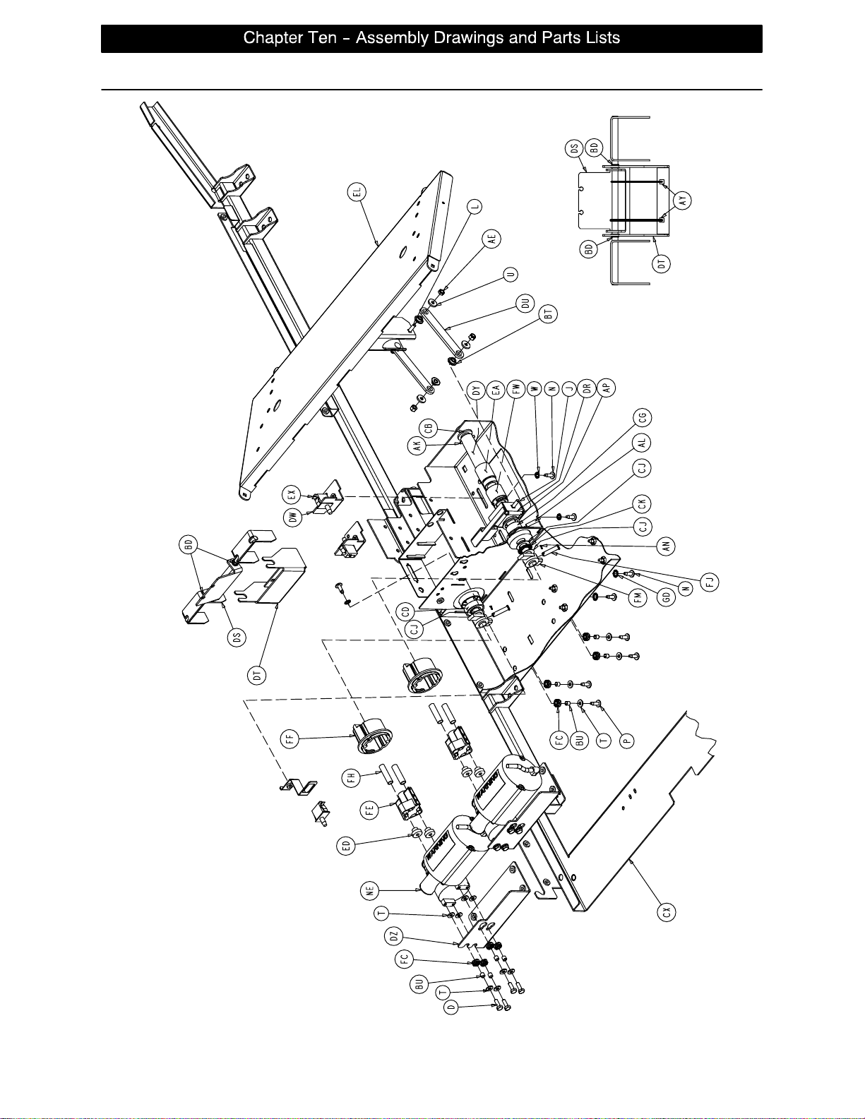
Litter Assembly and Options
CPR RELEASE
page 10 −27
Page 85
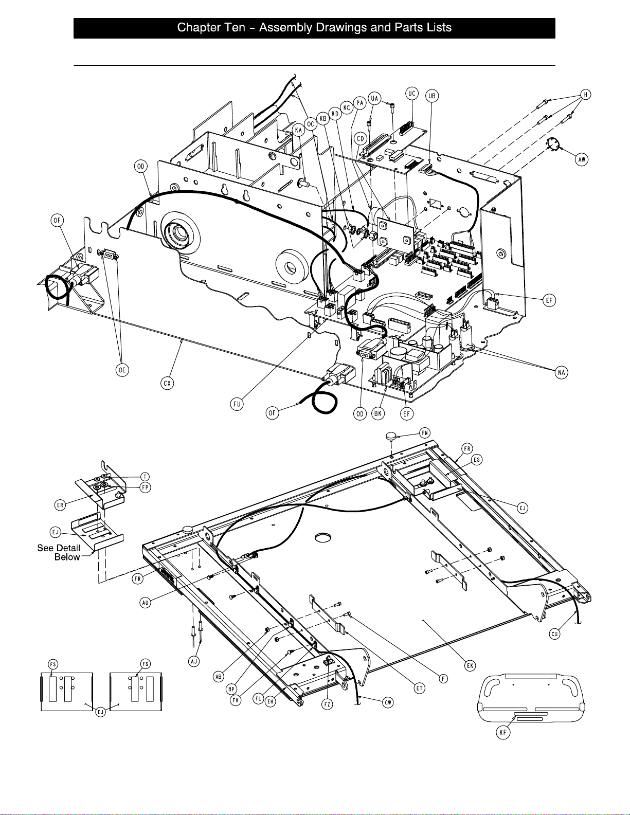
Litter Assembly and Options
CPR SLIDE BRACKET DETAIL
page 10 −28
Page 86
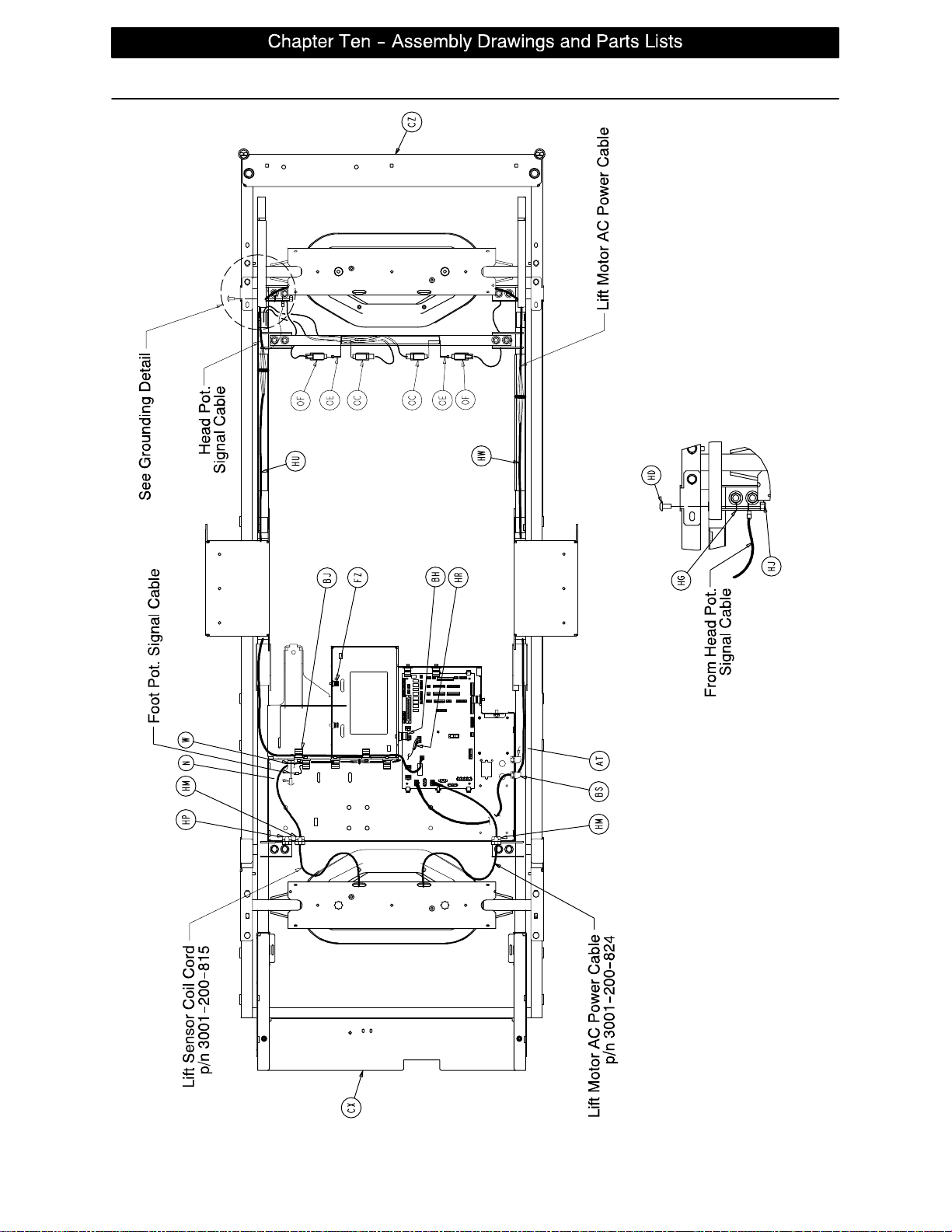
Litter Assembly and Options
HEAD ENDFOOT END
GROUNDING DETAIL
page 10 −29
Page 87
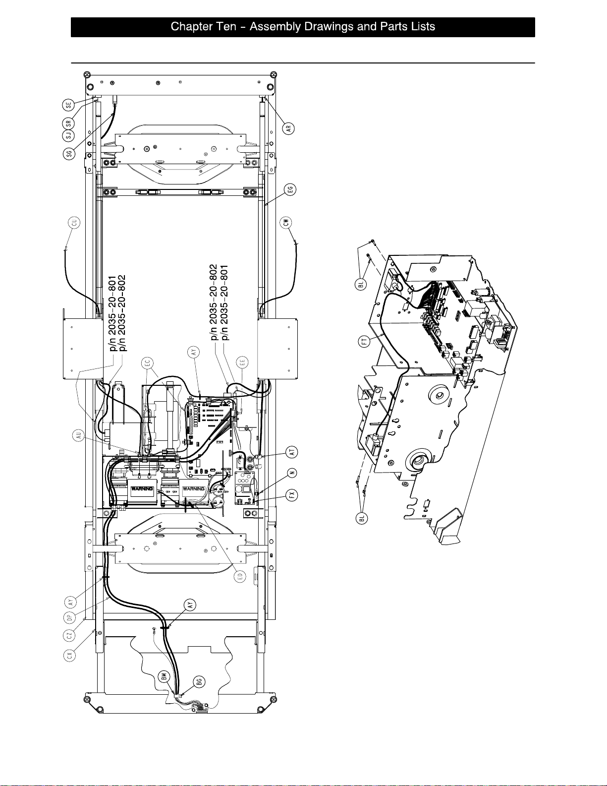
Litter Assembly and Options
HEAD ENDFOOT END
page 10 −30
SIDERAIL EXTENSION CABLE ROUTING
Page 88
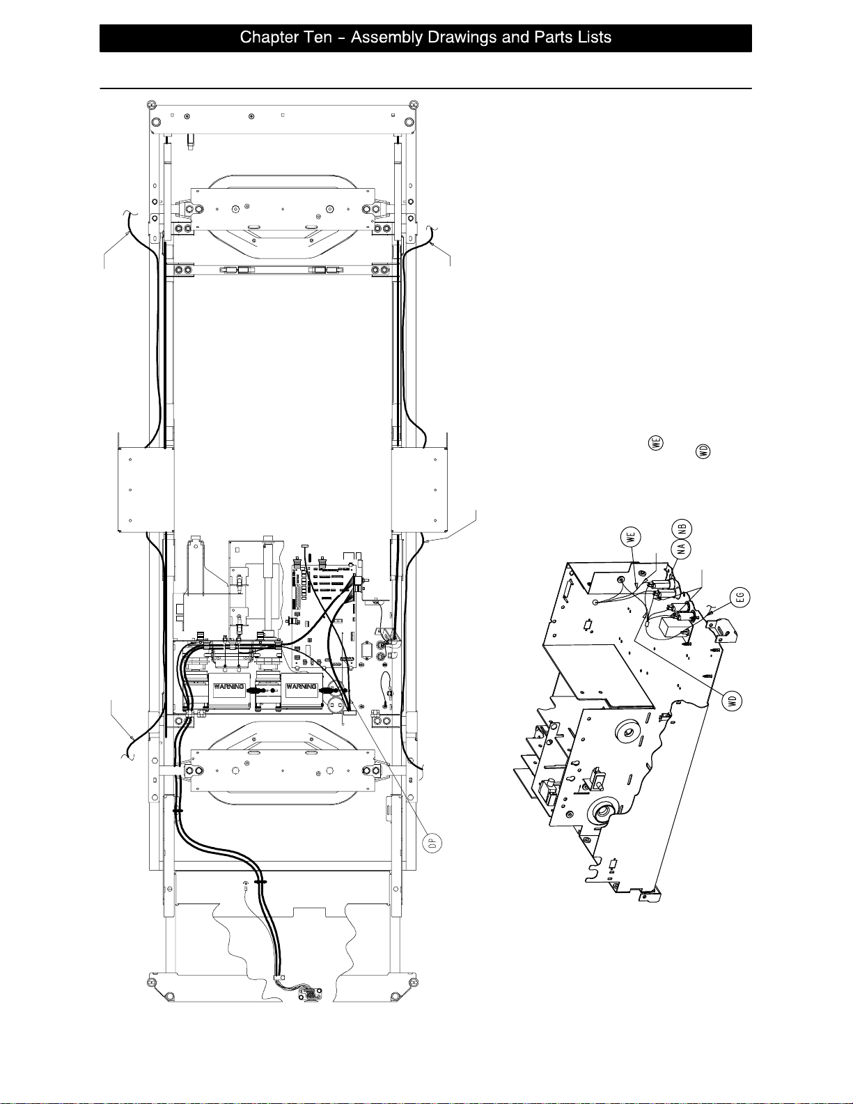
Litter Assembly and Options
HEAD ENDFOOT END
2033−22−810
Routed to Siderail
2033−22−807
Routed to Siderail
2033−22−810
Routed to Siderail
2033−22−809
Routed to Siderail
Blue wire of item
Blue wires of item
Connect one Faston connector to the normally
open lead on the CPR drop cherry switch and
one Faston to the comm. lead
page 10 −31
Page 89

Litter Assembly and Options
2030−231−10 Common Litter Components
Item Part No. Part Name Qty. Item Part No. Part Name Qty.
A3−23 Hex Hd. Cap Screw 2 BR 59−773 Push Spacer 4
B3−74 Hex Hd. Cap Screw 3 BS 59−774 Locking PCB Support 1
C3−78 Hex Hd. Cap Screw 4 BT 81−268 Flange Bearing 14
D3−214 Hex Hd. Cap Screw 8 BU 715−1−133 Rel. Valve Stop Sleeve 18
E3−347 Hex Hd. Cap Screw 4 BW 988−2−708 Shock Caution Label 1
F4−32 Soc. Hd. Cap Screw 4 BX 2020−34−758 Calf Section Rest 2
G4−85 Soc. Hd. Cap Screw 2 BY 2025−31−62 Pot. Actuator Link 1
H4−101 Soc. Hd. Cap Screw 4 BZ 2025−31−804 Ground Jumper 4
J5−19 Carriage Bolt 18 CA 2025−31−805 Ground Strap 6
K5−22 Carriage Bolt 4 CB 2025−32−68 Flange Bearing 2
L5−23 Carriage Bolt 3 CD 2025−32−76 Ball Bearing 2
M7−58 Truss Hd. Torx 5 CE 2025−32−77 Fowler Actuator Link 2
N7−63 Truss Hd. Torx 19 CF 2025−32−82 Hydraulic Dampener 2
P7−65 Truss Hd. Torx 16 CG 2025−32−84 Fowler Screw Up Stop 1
R11−4 Washer 16 CH 2025−32−85 Fowler Screw Down Stop 1
S11−53 Washer 10 CJ 2025−32−86 Thrust Washer 5
T11−63 Washer 41 CK 2025−32−87 Roller Cage Bearing 2
U11−158 Washer 24 CL 2025−231−61 Pot. Timing Clamp 1
W13−10 Ext. Tooth Lock Washer 16 CM 2025−231−88 Fowler Link 2
X13−18 Ext. Tooth Lock Washer 14 CN 2025−231−90 Torque Tube Pivot Brg. 2
Y13−32 Ext. Tooth Lock Washer 2 CP 2025−231−99 Bed Extender Rel. Lever 2
Z14−7 Washer 2 CR 2025−231−112 Bed Extender Pin Lock 2
AB 16−3 Nylock Nut 4 CS 2025−232−89 Fowler Nut Box 1
AC 16−28 Nylock Nut 22 CT 2025−232−90 Fowler Ball Screw 1
AD 16−35 Nylock Nut 8 CU 2035−31−48 Short CPR Cable 1
AE 16−102 Nylock Nut 8 CW 2035−31−49 Long CPR Cable 1
AF 3−224 Hex Washer Hd. Screw 16 CX 2035−31−50 Scale Frame Weldment 1
AG 25−79 Rivet 2 CY 2035−31−51 Torque Tube Weldment 1
AH 25−142 Rivet 29 CZ 2035−31−54 Iso. Frame Weldment 1
AJ 25−147 Rivet 4 DA 2035−31−55 Head End Crosstube 1
AK 26−12 Roll Pin 2 DB 2035−31−57 Bed Extender Weldment 1
AL 26−168 Spiral Pin 2 DC 2035−31−64 Torque Tube Ret. Brkt., Lt. 1
AN 27−17 Cotter Pin 2 DD 2035−31−65 Torque Tube Ret. Brkt., Rt. 1
AP 28−120 External Retaining Ring 3 DE 2035−31−66 Torque Block Channel 2
AR 30−27 Strain Relief 1 DF 2035−31−94 Foot Support Cover 1
AS 30−36 Grommet 4 DH 2035−31−100 Wire Channel Cover 2
AT 30−47 Right Angle Strain Relief 1 DJ 2035−31−115 Roller Bracket Cover, Rt. 1
AU 30−52 Snap Bushing 4 DK 2035−31−116 Roller Bracket Cover, Lt. 1
AW 37−221 Hole Plug 1 DL 2035−31−126 Protective Sleeve 2
AX 38−111 Cable Tie 10 DM 2035−31−127 Nylon Stop 2
AY 3 8−151 Cable Tie 17 DR 2035−32−52 Gatch Trigger Weldment 1
AZ 38−382 Compression Spring 2 DS 2035−32−54 CPR Release Wldmt. Brkt. 1
BA 44−29 Black Foam Tape 1 DT 2035−32−72 CPR Release Pivot Brkt. 1
BB 44−32 1” Wide Poly Tape 50” DU 2035−32−77 Gatch Actuator Link 2
BC 52−104 Cable Clamp 2 DW 2035−32−79 Act. Box Cherry Swch. Brkt. 2
BD 52−759 Flange Bearing 2 DX 2035−32−84 Gatch Screw Up Stop 1
BE 52−762 Nyliner Bushing 2 DY 2035−32−85 Gatch Screw Down Stop 1
BF 58−56 Black Edge Trim 18” DZ 2035−32−88 Act. Box Motor Mtg. Brkt. 2
BG 58−76 Drive Fastener 2 EA 2035−32−90 Gatch Ball Screw Ass’y1
BH 59−133 Push−Mount Wire Clip 1 EB 2035−32−96 Ball Screw Cover 1
BJ 59−135 Push−Mount Wire Clip 8 EC 2035−32−801 Gatch Limit Switch Cable 1
BK 59−157 Power Supply 1 ED 2035−32−802 Fowler/CPU Jumper Cable 1
BL 59−727 Jack Screw 4 EE 2035−32−803 Fowler Pot. Cable 1
BM 59−743 Wire Harness Clip 2 EF 2035−32−804 Fuse/PCB Cable 1
BN 59−751 Locking Circuit Bd. Supt. 6 EG 2035−32−805 CPU/Power Supply Cable 1
BP 59−767 Cable Clamp 2 EH 2035−33−50 Fowler Frame Weldment 1
page 10 −32
Page 90

Litter Assembly and Options
2030−231−10 Common Litter Components (Continued)
Item Part No. Part Name Qty. Item Part No. Part Name Qty.
EJ 2035−33−62 CPR Release Slide Brkt. 2 FK 3000−300−477 CPR Conduit Stud 6
EM 2035−35−50 Foot Section Weldment 1 FL 3000−300−478 CPR Conduit Clamp 6
EP 2035−231−85 Seat Section Cover 2 FM 3001−200−228 Mounting Standoff 2
ET 2035−400−565 Siderail Guide Bracket 2 FN 3001−300−8 Thigh Bumper 4
EU (page 10−35) Actuator Box Cover Ass’y 1 FP 3001−300−99 Flange Bearing 10
EX 3000−300−58 Switch Plunger 2 FR 3001−300−603 CPR Release Label 2
EY 3000−300−99 Modified Bushing 10 FS 3001−300−663 Velcro Strip 10
EZ 3000−300−115 Standoff 4 FT 3001−300−877 Siderail Extension Cable 1
FA 3000−300−349 Head/Foot Board Post Cap 4 FU 2033−700−2 CPU Assembly 1
FB 3000−300−353 Roller 8 FW 5000−30−366 Fowler Nut Adapter 1
FC 3000−300−442 Fowler Drive Grommet 16 FX 5010−80−7 Power Supply Gd. Cable 1
FD 3000−300−455 CPR Isolation Bushing 4 FY 8800−380−000 Neoprene Sponge 1.5’
FE 3000−300−456 CPR Isolator 2 FZ 8815−001−100 Wire Mount Clip 4
FF 3000−300−461 CPR Decoupler 2 GA 11−310 Washer 2
FG 3000−300−462 CPR Wing 2 GB 11−2 Washer 1
FH 3000−300−464 CPR Engagement Spring 4 GC 7−52 Truss Hd. Torx 4
FJ 3000−300−473 Clevis Pin 2 GD 13−38 Ext. Tooth Lock Washer 2
2033−42−11 TriaDyne III Litter Components
Item Part No. Part Name Qty. Item Part No. Part Name Qty.
N7−63 Truss Hd. Torx Screw 1 JH 34−22 Cord Clamp 1
W13−10 Ext. Tooth Lock Washer 1 JJ 36−46 220V Ground Label 1
AF 23−25 H. Wash. Hd. Tap. Screw 2 JK 36−115 Earth Ground Label 1
AG 25−79 Rivet 16 JL 1550−90−1 Hosp. Grade Plug Label 1
DG 2033−31−97 Seat Section Skin 1 JM 2011−1−104 Explosion Danger Label 1
DP 2033−31−802 Foot Board/CPU Cable 1 JN 2011−1−215 Grounding Lug 1
EG 2033−31−801 Frame AC Power Cable 1 JP 2035−231−70 A/C Filter Mtg. Plate 1
EK 2033−33−63 Fowler Skin 1 JR 2035−31−803 Power Inlet Cable 1
EL 2033−34−50 Thigh Section Weldment 1 JS 3000−300−002 Plastic Clip Nut 4
ER 2033−233−64 Quick Drop Rel. Brkt., Lt. 1 JT 3000−300−350 Head End Bumper Strip 2
ES 2033−233−65 Quick Drop Rel. Brkt., Rt. 1 WA 4−127 Soc. Hd. Cap Screw 4
EX 3000−300−58 Switch Plunger 1 WB 16−7 Fiberlock Nut 4
FN 3001−300−8 Thigh Bumper 2 WC 34−22 Insulated Metal Clamp 4
FU 3001−407−920 Scale CPU/Headwall PCB 1 WD 2033−31−803 Perc. Pwr. Supply Cable 1
JA 4−5 Soc. Hd. Cap Screw 1 WE 2033−31−807 Percussor AC Pwr. Cable 1
JB 4−126 But. Hd. Cap Screw 2 WF 2033−33−11 Cherry Switch Bracket 1
JC 7−58 Truss Hd. Torx Screw 2 WG 2033−34−758 Foot Section Rest 4
JD 16−14 Nylock Nut 1 WH 59−767 Insulated Cable Clamp 4
JE 16−23 Nylock Nut 2 WJ 16−7 Nylock Nut 4
JF 16−33 Nylock Nut 2 WK 3001−300−7 Jack Screw 4
JG 23−80 Truss Hd. Tapping Screw 4 WL 2030−31−205 Cover, No Scale 1
page 10 −33
Page 91

Litter Assembly and Options
2033−32−15 TriaDyne III Domestic Components 2030−30−151 Low−Sounding Beeper Option
Item Part No. Part Name Qty. Item Part No. Part Name Qty.
NA 59−179 Circuit Breaker 2 PA 3001−508−869 Low Beeper Cable 1
ND 2033−90−1 Specification Label 1
NE 2035−300−705 Fowler Drive Assembly 2
NF 39−254 Power Cord 1
2033−32−20 TriaDyne III Height Option 2030−40−150 Scale & Chaperone Options
Item Part No. Part Name Qty. Item Part No. Part Name Qty.
HS 2030−331−52 Head End Header Wldmt. 1 OA 13−32 Ext. Tooth Lock Washer 4
HT 2033−331−53 Foot End Header Wldmt. 1 (page 10−57) Foot Board 1
OC 2035−317−805 Load Cell Cable, Head 2
OD 2035−317−804 Load Cell Cable, Foot 2
OE 3001−300−7 M/F Screw 8
OF 3001−307−57 Load Cell 4
page 10 −34
Page 92
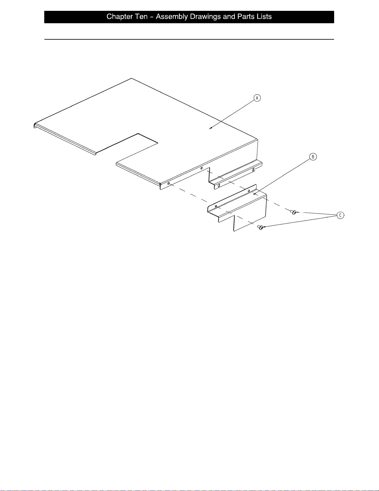
Actuator Box Cover Assembly
Assembly part number 2035−432−75 (reference only)
Item Part No. Part Name Qty.
A 2035−332−75 Main Actuator Box Cover 1
B 2035−332−76 Actuator Box Side Cover 1
C7−58 Truss Hd. Torx 2
page 10 −35
Page 93
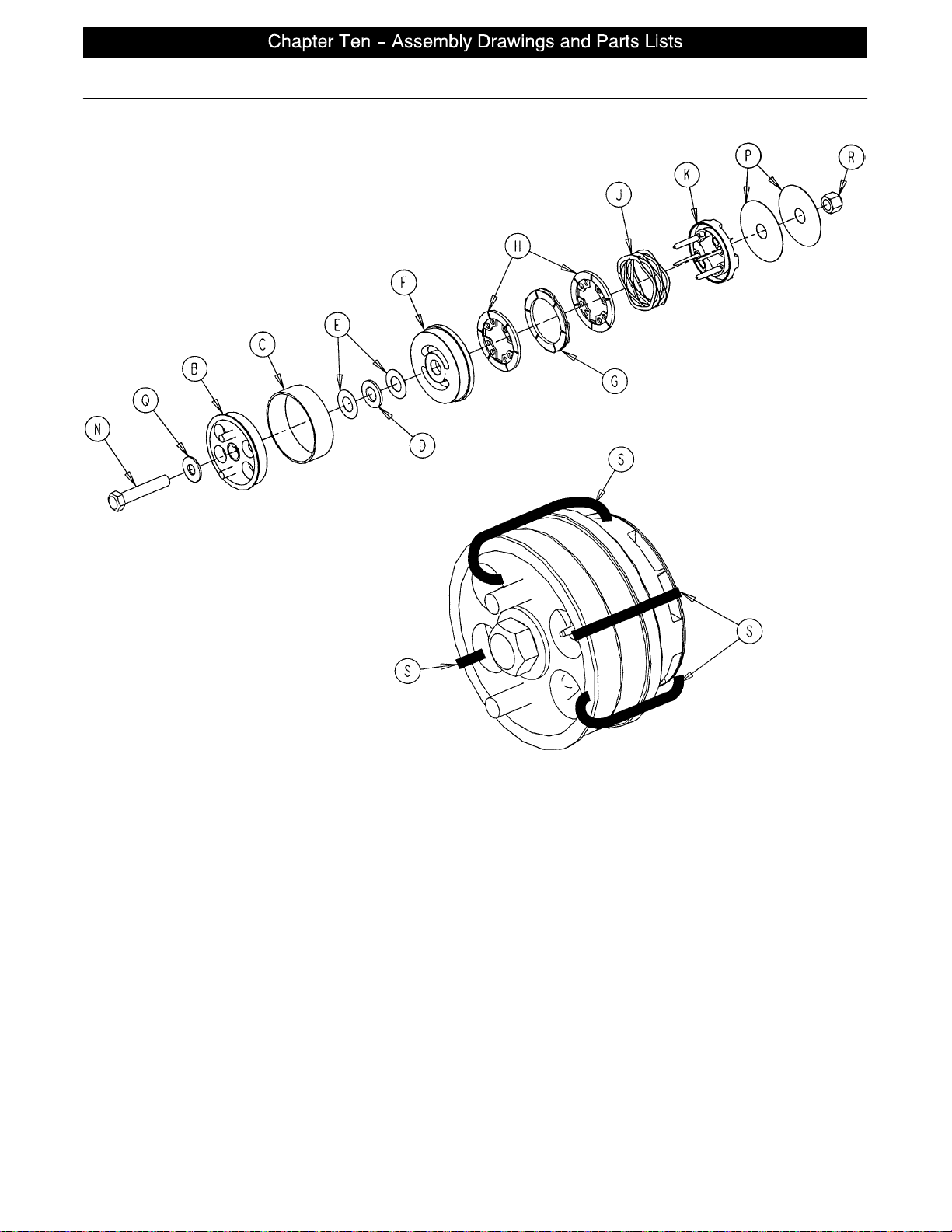
3001−300−775 Fowler Brake Kit Assembly
page 10 −36
Item Part No. Part Name Qty.
B 3001−300−455 CPR Coupler Assembly 1
C 3000−300−465 CPR Clutch Spring 1
D81−212 Thrust Needle Roller Brg. 1
E 3000−200−224 Idler Gear Thrust Washer 2
F 3001−300−569 Brake Cup 1
G 3001−300−552 CPR Brake Disc 1
H 3001−300−551 CPR Spring Cup 2
J 3001−300−563 CPR Brake Spring 1
K 3001−300−570 CPR Spring Cup 1
N3−64 Hex Hd. Cap Screw 1
P 3000−200−245 Flat Washer 2
Q11−193 Heavy Flat Washer 1
R16−12 Nylock Nut 1
S 3000−300−11 3 8 ” Wire Tie 4
Page 94
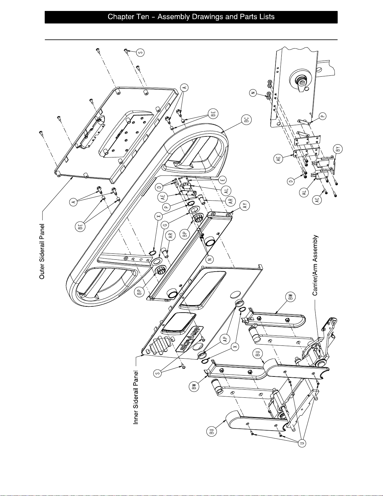
Head End Siderail Assembly
LEFT SIDERAIL SHOWN
page 10 −37
Page 95
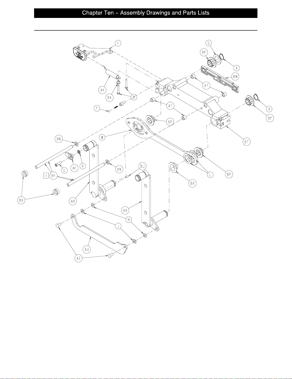
CARRIER/ARM ASSEMBLY
LEFT SIDERAIL SHOWN
Head End Siderail Assembly
page 10 −38
Page 96
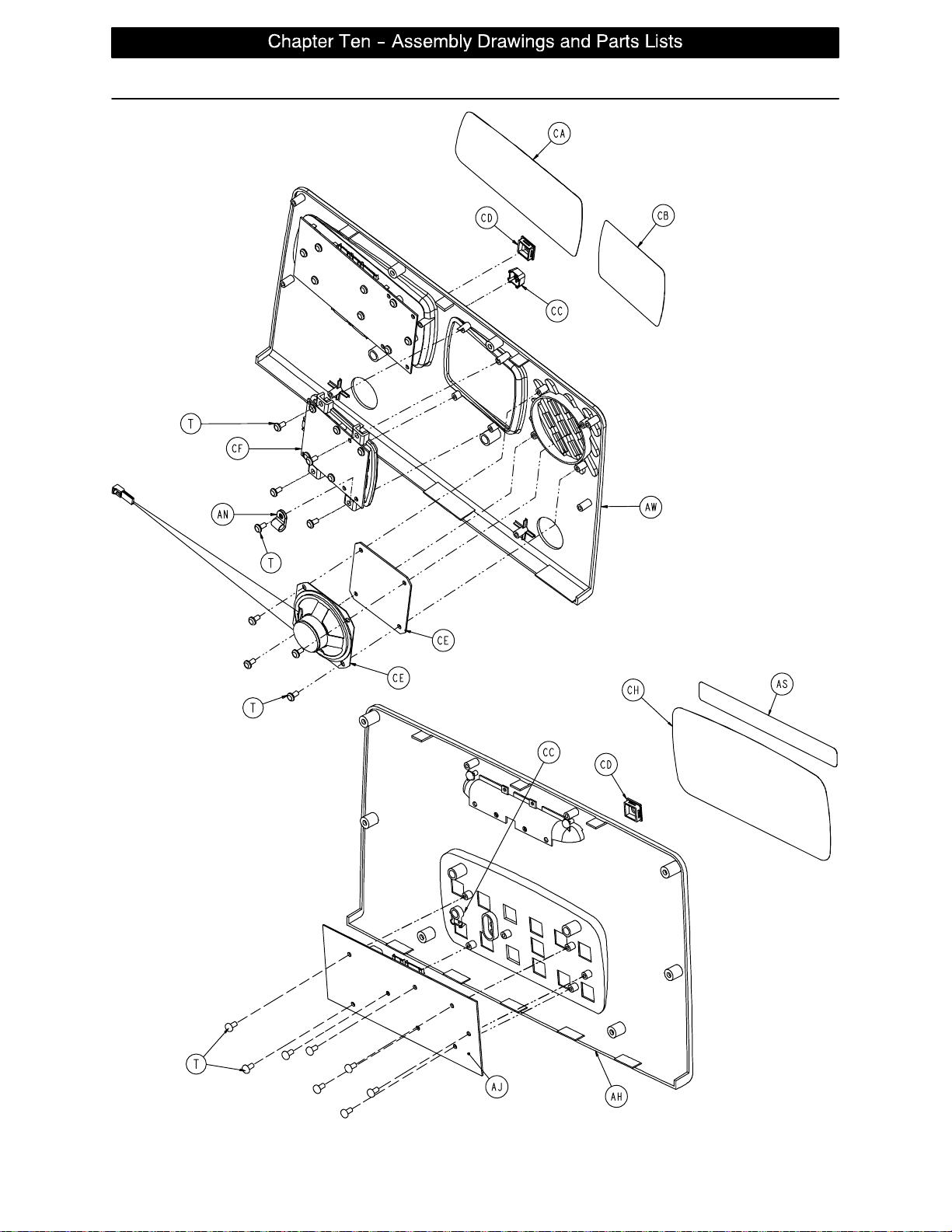
Head End Siderail Assembly
SIDERAIL OUTER PANEL
ASSEMBLY
SIDERAIL INNER PANEL
ASSEMBLY
page 10 −39
Page 97
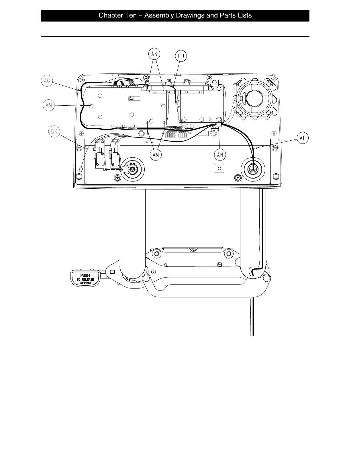
Head End Siderail Assembly
page 10 −40
LEFT HEAD END SIDERAIL WIRE ROUTING
Page 98
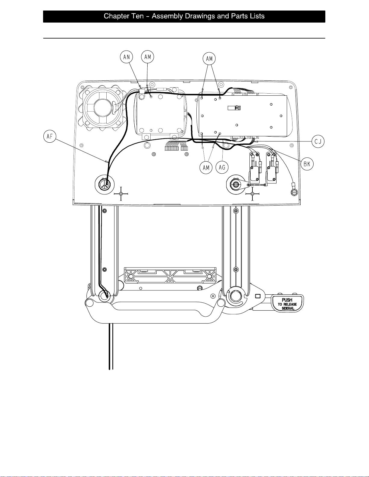
Head End Siderail Assembly
RIGHT HEAD END SIDERAIL WIRE ROUTING
page 10 −41
Page 99

Head End Siderail Assembly
2030−401−105 Left Standard Components 2030−401−205 Right Standard Components
Item Part No. Part Name Qty. Item Part No. Part Name Qty.
A3−226 Hex Washer Hd. Screw 4 A 3−226 Hex Washer Hd. Screw 4
B3−344 Hex Hd. Screw 2 B 3−344 Hex Hd. Screw 2
C4−9 Soc. Hd. Cap Screw 1 C 4−9 Soc. Hd. Cap Screw 1
D4−101 Soc. Hd. Cap Screw 2 D 4−101 Soc. Hd. Cap Screw 2
E4−127 Soc. Hd. Cap Screw 2 E 4−127 Soc. Hd. Cap Screw 2
F (page 10−44) Release Lever Ass’y, Left 1 F (page 10−45) Release Lever Ass’y, Right 1
G11−343 Shim Washer 3 G 11−343 Shim Washer 3
H11−377 Washer 2 H 11−377 Washer 2
J11−491 Steel Shim Washer 2 J 11−491 Steel Shim Washer 2
K13−10 Ext. Tooth Lock Washer 1 K 13−10 Ext. Tooth Lock Washer 1
L14−93 Washer 2 L 14−93 Washer 2
N16−23 Fiberlock Nut 2 N 16−23 Fiberlock Nut 2
P16−69 Twin Fastener 1 P 16−69 Twin Fastener 1
R23−88 High−Low Tapping Screw 1 R 23−88 High−Low Tapping Screw 1
S23−90 High−Low Tapping Screw 8 S 23−90 High−Low Tapping Screw 8
T23−112 High−Low Tapping Screw 16 T 23−112 High−Low Tapping Screw 16
U1−72 Ph. Flat Hd. Mach. Screw 4 U 1−72 Ph. Flat Hd. Mach. Screw 4
W (page 10−46) Latch Ass’y, Head, Left 1 W (page 10−47) Latch Ass’y, Head, Right 1
X28−128 Retaining Ring 6 X 28−128 Retaining Ring 6
Y (page 10−48) Detent Clip Assembly 1 Y (page 10−48) Detent Clip Assembly 1
AB 2033−401−130 Arm Wldmt., Lt., Hd., Ft. 1 AB 2033−401−230 Arm Wldmt., Rt., Hd., Ft. 1
AC 2035−20−60 Limit Switch Cam 1 AC 2035−20−60 Limit Switch Cam 1
AE 2035−20−62 Limit Switch Bracket 1 AE 2035−20−62 Limit Switch Bracket 1
AF 2035−20−802 Siderail Cable 1 AF 2035−20−802 Siderail Cable 1
AG 2035−20−804 Main Outside Cable, Lt. 1 AG 2035−20−803 Main Outside Cable, Rt. 1
AH (page 10−49) Outer Panel Assembly 1 AH (page 10−49) Outer Panel Assembly 1
AJ 2035−400−900 Outside Circuit Board 1 AJ 2035−400−900 Outside Circuit Board 1
AK 3000−200−334 Release Lever Spring 1 AK 3000−200−334 Release Lever Spring 1
AL 3000−300−41 Micro Switch 1 AL 3000−300−41 Micro Switch 1
AM 3000−300−114 Cable Tie 5 AM 3000−300−114 Cable Tie 5
AN 3000−300−478 CPR Conduit Clamp 1 AN 3000−300−478 CPR Conduit Clamp 1
AP 3000−400−513 Wear Bushing 2 AP 3000−400−513 Wear Bushing 2
AR 3000−400−523 Panel Spacer 2 AR 3000−400−523 Panel Spacer 2
AS 3000−400−556 Warning Label 1 AS 3000−400−556 Warning Label 1
AT 3000−400−557 Sleeve Bearing 4 AT 3000−400−557 Sleeve Bearing 4
AU 3001−400−11 Head End Timing Link 1 AU 3001−400−11 Head End Timing Link 1
AW (page 10−50) Inner Panel Assembly, Lt. 1 AW (page 10−50) Inner Panel Assembly, Rt. 1
AX 3001−401−128 Arm Wldmt., Lt., Hd., Hd. 1 AX 3001−401−228 Arm Wldmt., Rt., Hd., Hd. 1
AZ 3001−400−501 Linkage Rivet 2 AZ 3001−400−501 Linkage Rivet 2
BC 3001−400−515 Head Rail 1 BC 3001−400−515 Head Rail 1
BD 3001−400−555 Mounting Bracket 1 BD 3001−400−555 Mounting Bracket 1
BE 3001−400−558 SIderail Spacer 4 BE 3001−400−558 SIderail Spacer 4
BF 2035−400−570 Glide Rod 2 BF 2035−400−570 Glide Rod 2
BJ 3002−400−505 Bypass Pin 1 BJ 3002−400−505 Bypass Pin 1
BM 3002−400−511 Glide Rod Bumper Pad 1 BM 3002−400−511 Glide Rod Bumper Pad 1
BN 3002−400−512 Bumper Washer 2 BN 3002−400−512 Bumper Washer 2
BP 3002−400−513 Pivot Bushing 6 BP 3002−400−513 Pivot Bushing 6
BR 3002−400−519 Latch Bushing 1 BR 3002−400−519 Latch Bushing 1
BT 3002−400−528 Carrier 1 BT 3002−400−528 Carrier 1
BU 5000−20−5 Inner Arm Cover 2 BU 5000−20−5 Inner Arm Cover 2
BW 3001−400−619 Outer Arm Cover 2 BW 3001−400−619 Outer Arm Cover 2
BX 30−40 Grommet 2 BX 30−40 Grommet 2
page 10 −42
Page 100
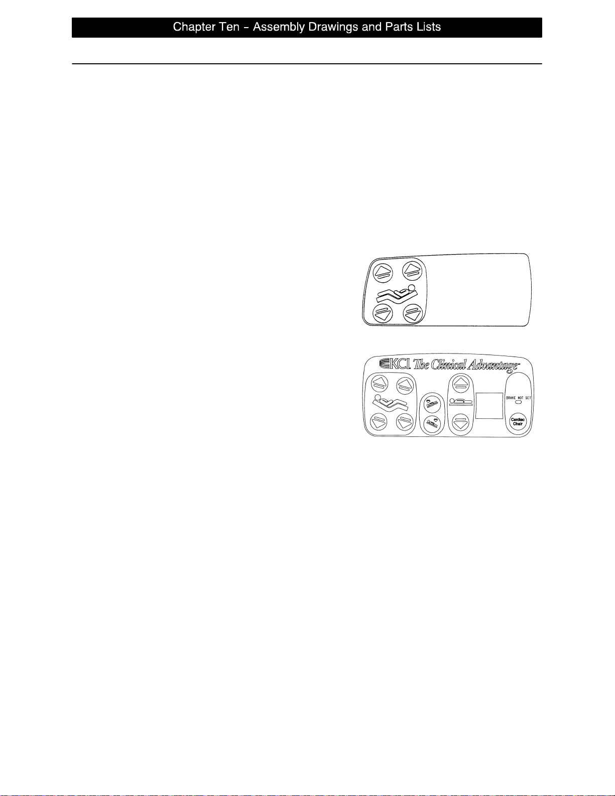
Head End Siderail Assembly
2033−401−105 Left Rail − TriaDyne III 2033−401−205 Right Rail − TriaDyne III
Item Part No. Part Name Qty. Item Part No. Part Name Qty.
D4−101 Soc. Hd. Cap Screw 2 D 4−101 Soc. Hd. Cap Screw 2
E4−127 Soc. Hd. Cap Screw 2 D 4−127 Soc. Hd. Cap Screw 2
P16−69 Twin Fastener 1 P 16−69 Twin Fastener 1
N16−23 Fiberlock Nut 2 N 16−23 Fiberlock Nut 2
AE 2035−20−62 Limit Switch Bracket 1 AE 2035−20−62 Limit Switch Bracket 1
AL 2033−300−41 Micro Switch 2 AL 2033−300−41 Micro Switch 2
AY 3001−400−130 Supt. Wldmt., Hd. End, Lt. 1 AY 3001−400−230 Supt. Wldmt., Hd. End, Rt. 1
BK 2033−22−810 Head End Switches Cable 1 BK 2033−22−810 Head End Switches Cable 1
BY 2033−31−11 Snap Switch Link Wire 1 BY 2033−31−11 Snap Switch Link Wire 1
2033−20−11 TriaDyne III Siderail
Item Part No. Part Name Qty.
CA 2035−000−100 Label, Standard, Left 1
CA 2035−000−200 Label, Standard, Right 1
CC 3001−400−953 Switch Cap 26
CD 3001−400−522 Filler Cap 20
CE 3001−400−517 Speaker Seal 2
CF 3001−400−535 Inner Panel Blank Module 2
CH 2033−000−300 Label, Standard, Left 1
CH 2033−000−400 Label, Standard, Right 1
Right Inner Siderail Label
Right Outer Siderail Label
page 10 −43
 Loading...