

Page 1

1688 4K Camera System
with Advanced Imaging Modality
1688010000
1688210105
1688310130
1688610122
1688710105
Page 2

Page 3

Contents
Warnings and Cautions ........................................................................... 1
Cautions ......................................................................................................................1
Warnings: General ...................................................................................................1
Warnings: SPY Mode ...............................................................................................3
Operating a Light Source ......................................................................................4
Product Description and Intended Use ................................................. 5
Indications .................................................................................................................. 6
The Camera Console ...............................................................................................7
The Camera Head ....................................................................................................9
Additional Features of the Pendulum Camera Head ............................... 10
The C-Mount Coupler .......................................................................................... 12
Device Compatibility ........................................................................................... 13
Setup ......................................................................................................15
Setting Up the Console ...................................................................................... 16
Wiring Diagram ..................................................................................................... 18
Setting Up the Camera Head ............................................................................ 19
Setting Up the Coupler ....................................................................................... 20
Installing the Soaking Cap ................................................................................ 22
SPY Mode Requirements ................................................................................... 23
Operation ............................................................................................... 24
Powering the Console On/O .......................................................................... 24
Performing the White Balance Test ................................................................ 24
Controlling Remote Video Accessories ......................................................... 25
Using the Touchscreen Interface..................................................................... 26
Using the Camera Head Buttons ..................................................................... 30
Using the Display Monitor Menu .................................................................... 33
Programming Camera Head Buttons ............................................................ 36
Advanced Features ............................................................................................... 37
Troubleshooting ....................................................................................38
Reprocessing .......................................................................................... 42
Cleaning and Disinfecting the Console ........................................................ 42
Cleaning, Disinfecting, and Sterilizing the Camera Head ...................... 43
Materials and Equipment .................................................................................. 45
Maintenance ..........................................................................................50
Inspecting the Console ....................................................................................... 50
Page 4

Inspecting the Camera Head ............................................................................ 50
Using Sterile Drapes ............................................................................................ 51
Storage ..................................................................................................................... 51
Replacing the Fuses ............................................................................................. 51
Periodic Maintenance Schedule ...................................................................... 52
Service Life .............................................................................................................. 52
Disposal .................................................................................................................... 52
Recycling Diagrams ............................................................................................. 53
Technical Specications ........................................................................ 55
Electromagnetic Compatibility ........................................................................ 56
Symbol Denitions ................................................................................ 60
Page 5

Warnings and Cautions
In this manual, the terms and denitions below apply.
• Warning: Possible injury to the patient or user.
• Caution: Possible damage to the equipment.
• Note: More information to clarify the instructions.
Cautions
To avoid potential damage to this device, please note the following cautions.
1. Carefully unpack this device and check if any damage occurred during
shipment. If damage is detected, refer to the warranty.
2. Never sterilize the camera console, because the delicate electronics
cannot withstand this procedure.
3. Ensure that the electrical installation of the relevant operating room
complies with the NEC and CEC guidelines.
4. Always treat the camera system with care. The camera system contains
sensitive parts that are precisely aligned and may suer damage if
dropped or mistreated.
5. Repairs and equipment modications shall be performed only by Strykerauthorized personnel. Stryker Endoscopy assumes no product liability or
warranty responsibility for devices repaired by or purchased from thirdparty service organizations.
Warnings: General
To avoid potential serious injury to the user and the patient and/or damage to
this device, please note the following general warnings.
1. Federal (USA) law restricts this device to sale by or on the order of a
physician.
2. Read this operating manual thoroughly, especially the warnings, and be
familiar with its contents before connecting and using this device.
3. Although the product was fully tested at the factory before shipment,
the user should always test it for proper function prior to a surgical
procedure.
4. Always test that the endoscope produces a live, clear, correctly-oriented
image prior to using it in a procedure and immediately after any viewing
mode or setting is changed in the camera system.
5. The camera head surface may exceed 41°C (106°F) in operating
conditions with high ambient temperatures and it should be handled
with caution.
1
Page 6

6. The camera head and coupler are shipped non-sterile. You must sterilize
these devices before the rst use and after each use. To prevent device
damage and infection risk to the patient or user, follow all cleaning and
sterilization instructions in this manual.
7. To minimize electromagnetic interference that may impact functionality
of the 1688 Video Camera, position any active electrosurgical generator
and its cables at least 12 inches (30 cm) away from the camera console.
When the electrosurgical generator is placed on a boom with the camera
console, it is advised to position the generator on the lowest shelf.
8. Do not position the console so that it is dicult to disconnect the power
cord from the supply mains.
9. To avoid the risk of electric shock, this equipment must only be
connected to a supply mains with protective earth ground.
10. Portable multiple socket-outlets shall not be placed on the oor.
Additional portable multiple socket-outlets or extension cords shall not
be used with the equipment.
11. Use of third-party HDMI cables with the camera console is not
recommended due to potential problems with secure connections or
electromagnetic compatibility. Use the provided HDMI high speed cable
(or other Stryker-approved HDMI cable) with the camera console.
12. Never use the camera system in the presence of ammable or explosive
gases or in an oxygen-rich environment.
13. To prevent tampering, physically secure the device when not in use.
14. Disconnect the console from the electrical outlet when inspecting fuses.
15. Do not remove covers on the console, as doing so may cause damage to
electronics and/or electric shock.
16. Do not disassemble any part of the camera head; doing so may break the
seals, causing leakage and/or electric shock.
17. Attempt no internal repairs or adjustments not specically detailed in this
operating manual.
18. Do not repair or adjust the device through a third-party service
organization. Devices repaired by or purchased from third-party service
organizations could expose patients to signicant risk. These devices
are no longer validated by Stryker for cleanliness, disinfection, and
sterilization, or for safety and ecacy.
2
Page 7

Warnings: SPY Mode
IMPORTANT SAFETY NOTICE - LASER RADIATION:
SPY mode controls a Class1M laser emitted from the L11 LED
Light Source with Advanced Imaging Modality (0220230300), also
referred to as the “L11 LED Light Source.”
Use of controls or performance of procedures other than those
specied herein can result in hazardous laser radiation exposure
and can cause severe eye injury to the patient or user.
To avoid exposure to laser radiation, follow all warnings and
guidelines presented below and throughout this user manual.
1. Before using SPY mode, read and be familiar with all instructions and
warnings found in this user manual and the light source user manual.
2. Protect the camera system against unqualied use.
3. Wear eye protection as appropriate. Refer to any applicable regional
regulations or standards for personal protective equipment.
4. Do not manipulate tissue while Contrast mode (a SPY mode) is on.
5. When using SPY mode, do not view the light output with optical
instruments (for example, microscopes or magniers). Do not direct the
light output in SPY mode into an area where such instruments are likely
to be used.
6. Do not turn on SPY mode when the endoscope is outside of the patient’s
body.
7. When SPY mode is on, never look into the following apertures or direct
the light emitted from the apertures toward another person:
• the light cable connection on the light source (if the cable is not
attached)
• the end of the light cable (if the SafeLight™ adapter is attached)
• the endoscope tip
8. When SPY mode is on, never leave a SafeLight adapter attached to the
light cable without an endoscope attached. Laser radiation can continue
to emit from the adapter.
9. Disconnect the light cable from the light source only when the light
source is powered o or the light output is deactivated.
3
Page 8

Operating a Light Source
Please note the following warnings to avoid user or patient injury or product
damage when using a system with a light source. Note that the light source
adjustments described apply only to operating the light source manually (i.e.,
with Auto Light o).
IMPORTANT SAFETY NOTICE - HIGH TEMPERATURES:
When using a light source, re and/or severe injury may result to
the patient, user or inanimate objects if the instructions in this
manual are not followed.
All light sources can generate signicant amounts of heat
(exceeding 41°C/106°F) at the scope tip, the scope light post, the
light cable tip, and/or near the light cable adapter. Higher levels
of brightness from the light source result in higher levels of heat.
Always adjust the brightness level of the camera and the display
monitor before adjusting the brightness level of the light source.
If the brightness level of the light source can be adjusted, set it to
the minimum brightness necessary to adequately illuminate the
surgical site.
In addition, adjust the internal shutter of the camera higher in order
to run the light source at a lower intensity. Avoid touching the
scope tip or the light cable tip to the patient, and never place them
on top of the patient, as doing so may result in burns to the patient
or user. In addition, never place the scope tip, the scope light post,
the light cable adapter, or the light cable tip on the surgical drapes
or other ammable material, as doing so may result in re.
Always deactivate the light output from the light source before
removing the scope from the light cable or leaving the device
unattended. The scope tip, scope light post, light cable adapter, and
light cable tip will take several minutes to cool o after deactivating
the light output, and therefore may still result in re or burns to the
patient, user, or inanimate objects.
The warranty is void if any of the above warnings or cautions are disregarded.
4
Page 9

Product Description and Intended Use
The 1688 4K Camera System with Advanced Imaging Modality (or “1688Video
Camera”) is an endoscopic camera system that is used to produce live video
in the surgical eld during surgical endoscopic procedures. The system is
sensitive in the visible and infrared spectrum. The optical image is transferred
from the surgical site to the camera head by a variety of rigid and exible
scopes, which are attached to the camera head. The system consists of a
camera console and a camera head with an integral cable that connects to the
console. A coupler is also available for attaching a scope to the camera head.
The available models for each part are listed below.
Console
1688010000 16884K Camera Control Unit with Advanced Imaging
Modality
Camera Heads
1688210080 16884K Microscope Camera Head, C-Mount
1688210105 16884K Camera Head, C-Mount, with Advanced Imaging
Modality
1688310130 16884K Pendulum Camera Head with Integrated Coupler
1688610122 16884K Camera Head, Integrated Coupler, with Advanced
Imaging Modality
1688710105 16884K Inline Camera Head, C-Mount, with Advanced
Imaging Modality
Coupler
1688-020-122 4K Coupler, C-Mount, with Advanced Imaging Modality
1
Complete instructions are available in Stryker user manual P45082. Note that 1688210080 does not have the same intended use
or indications as stated in this user manual.
2
Not intended for use with SPY/ENV modes.
3
Not compatible with SPY/ENV modes.
4
Complete instructions are available in Stryker user manual P40880.
1, 2
3
4
Note: For complete system requirements to use the camera’s SPY mode,
see the user manual for the L11 LED Light Source with Advanced Imaging
Modality (0220230300), also referred to as the “L11 LED Light Source.”
The camera console is also packaged with the following connection cables:
• Remote cables, 2.5 mm to 3.5 mm (Qty: 2)
• HDMI high speed cable (Qty: 1)
• Hospital-grade power cord (Qty: 1)
5
Page 10

Contact your Stryker representative for availability of other cables that may be
required for alternate congurations.
Indications
The 1688 Video Camera is indicated for use in general laparoscopy,
nasopharyngoscopy, ear endoscopy, sinuscopy, and plastic surgery wherever
a laparoscope/endoscope/arthroscope/sinuscope is indicated for use.
A few examples of the more common endoscopic surgeries are listed below.
• laparoscopic cholecystectomy
• laparoscopic hernia repair
• laparoscopic appendectomy
• laparoscopic pelvic lymph node detection
• laparoscopically assisted hysterectomy
• laparoscopic and thorascopic anterior spinal fusion
• anterior cruciate ligament reconstruction
• knee arthroscopy
• small joint arthroscopy
• decompression xation
• wedge resection
• lung biopsy
• pleural biopsy
• dorsal sympathectomy
• pleurodesis
• internal mammary artery dissection for coronary artery bypass
• coronary artery bypass grafting where endoscopic visualization is
indicated
• examination of the evacuated cardiac chamber during performance of
valve replacement
The users of the 1688 Video Camera are general surgeons, gynecologists,
cardiac surgeons, thoracic surgeons, plastic surgeons, orthopedic surgeons,
ENT surgeons and urologists.
6
Page 11

The Camera Console
The camera console—or Camera Control Unit (CCU)—is the control center for
the 1688 Video Camera, and it processes the video and photographic images
produced during the surgical procedure.
Front Panel
The console front panel features a touchscreen where dierent menus can
be accessed. The touchscreen can be used to adjust camera settings (such as
Brightness, Zoom Level, and White Balance), select surgical specialties that
optimize camera performance for specic surgical procedures, and turn on
SPY mode. The touchscreen also allows activation of remote outputs, which
are commonly used with a Stryker digital capture console to record images
and video.
See the Operation section for more information about using the front panel.
321
1. Power Switch Powers the camera on and o
2. Touchscreen Allows navigation through dierent menus
for controlling the camera and adjusting
the video settings
3. Camera-Connector Port Connects to the 1688 Camera Head
7
Page 12

Rear Panel
The console rear panel provides ports for connecting the 1688 Video Camera
to other equipment such as a display monitor, a light source, and a device
control console and/or digital capture console.
9
1
2
3
7
654
8
1. HUB Port Connects to a Stryker device control console to
enable voice operation and/or graphic tablet
control
2. Remote Out 1 Connects to a video accessory remote input
3. Remote Out 2 Connects to a video accessory remote input
4. HDMI Out 1 HDMI 2.0 output (supports 4K UHD video
resolution)
5. HDMI Out 2 HDMI 2.0 output (supports 4K UHD video
resolution)
6. Light Source Port Connects to Stryker light source
7. AC Power Inlet Connects to AC mains with separable power
cord
8. Fuse Panel Contains two 1.6A 250V fuses (slow blow, high
breaking capacity 1500A, size 5mm x 20mm)
9. Equipotential
Ground Plug
Connects to a potential equalization conductor.
The resulting medical electrical system shall
follow all applicable IEC 60601-1 requirements.
8
Page 13
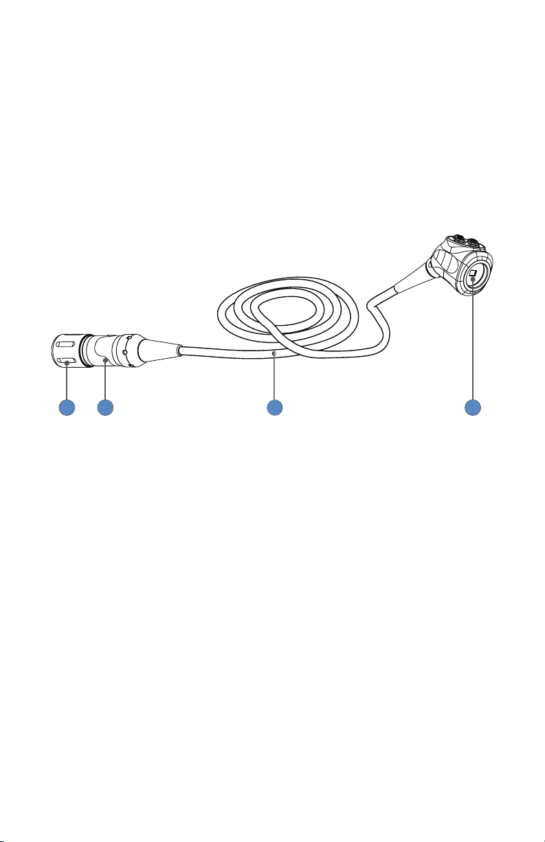
The Camera Head
The camera head connects to the camera console and produces video and
photographic images, which it relays to the camera console. Several controls
are accessible through a button keypad located on the top of the camera
head (see the Operation section).
See the Product Description section for the dierent camera head models that
are available. The 1688 4K Camera Head, C-Mount, with Advanced Imaging
Modality (1688210105) is shown below with a list of features that are common
to each camera head.
41 2 3
1. Soaking Cap Protects the cable connector during cleaning,
disinfection, and sterilization
2. Cable Connector Connects the camera head to the camera console
3. Camera Cable The camera cable length is 10 feet (3.05 m)
4. Camera Head Produces photographic and video images,
provides camera controls, and connects with
(1688210105 and 1688710105) or integrates
(1688310130 and 1688610122) a focusing coupler.
9
Page 14
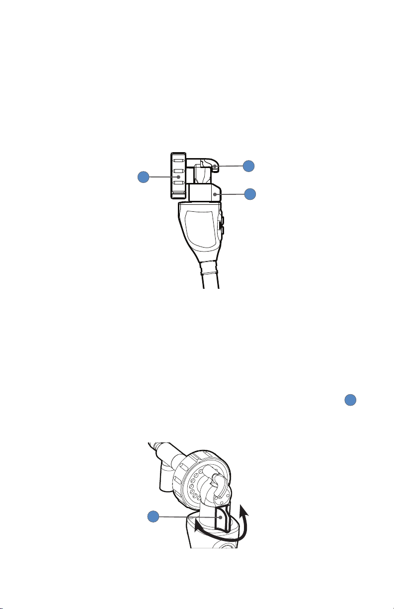
Additional Features of the Pendulum Camera Head
The 1688 4K Pendulum Camera Head with Integrated Coupler (1688310130)
utilizes each of the features described in the previous section, The Camera
Head, and it has additional features that are described below.
The Pendulum Camera is designed with a 90° angle between the camera head
and the scope to allow for easier access during urological procedures. The
camera also incorporates image focusing and rotation features described in
the following sections.
2
1
3
1. Endobody Clamp Secures the endoscope to the camera head
2. Endobody Brake Prevents rotation of the endoscope
3. Focusing Knob Adjusts the focus of the camera head
Adjusting the Focus (1688310130 only)
To adjust the focus of the Pendulum Camera Head, slide the focusing knob 1
from side to side as needed (i.e., in the direction of the Camera button or the
Menu button).
1
10
Page 15
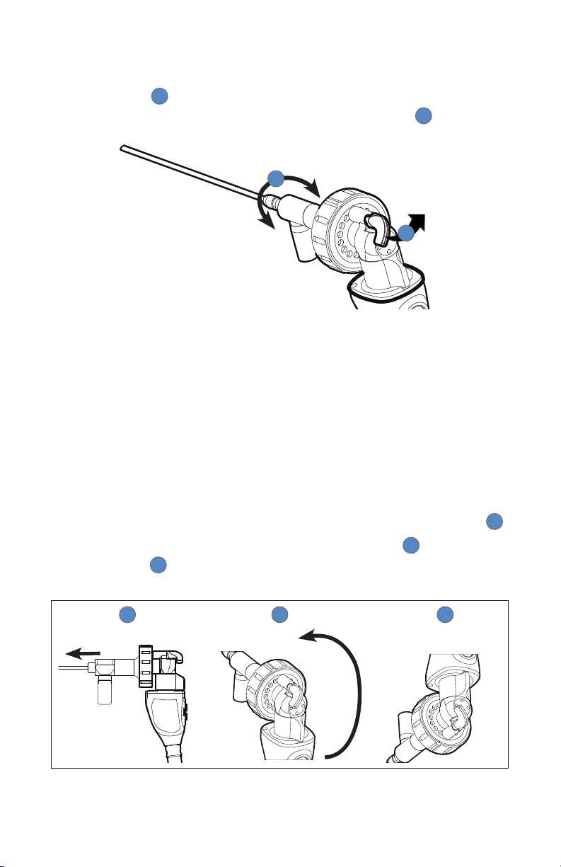
Rotating the Image (1688310130 only)
To allow rotation of the endoscope inside the endobody clamp, release the
endobody brake 1 by rotating it counterclockwise (when facing the camera
head buttons). The endoscope can then be rotated as needed 2.
2
1
To prevent the endoscope from rotating inside the endobody clamp, lock
the endobody brake by rotating it clockwise (when facing the camera head
buttons). If the endoscope is not secured in a xed position, slightly rotate the
endobody clamp in either direction until the lock engages with an audible
click.
Automatic Image Flip (1688310130 only)
By default, the Pendulum Camera Head will automatically ip the video image
back to the initial orientation when the camera is rotated 180°.
1. Hold the camera head with the endoscope axis parallel to the ground 1.
2. Rotate the camera head from the “cable down” position 2 to the “cable
up” position 3. Once the camera head cable is fully rotated, the video
image will rotate back to the initial orientation.
1 2 3
The video image will also ip when the camera head is rotated from the “cable
up” position to the “cable down” position.
11
Page 16
If you want to change the Pendulum Auto Flip setting, follow these steps:
1. Hold down the Settings button on the camera console Home screen for
about 5 seconds.
2. Select Options.
3. Press the right arrow to advance to the second menu page, and change
the Pendulum Auto Flip setting.
4. Click X in the top-right corner to return to the Home screen.
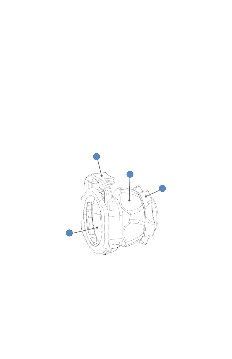
The C-Mount Coupler
The coupler threads onto the face of the camera head, enabling a scope to be
attached to the camera. It provides a focusing ring to adjust image sharpness.
It is recommended to use the camera with the 4K Coupler, C-Mount, with
Advanced Imaging Modality (1688-020-122). The 4K Coupler enables use of
SPY mode when the camera is connected to the the proper system. Refer to
Stryker user manual P40880 for complete 4K Coupler instructions.
2
3
4
1
1. Scope End Receives the endoscope
2. Endobody Clamp Secures the scope to the coupler
3. Focusing Ring Adjusts the coupler focus
4. Rear Adapter Threads onto the camera head
12
Page 17

Device Compatibility
For optimal use, the 1688 Video Camera is designed to work with the L11 LED
Light Source (0220230300) and the Connected OR Hub (0240200100) with
software version 1.2.1 or higher. All features and instructions described in this
user manual apply to this system unless otherwise noted.
The 1688 Video Camera is also compatible with other light sources and digital
capture devices that are listed below. The features and instructions that are
dierent than the rest of this user manual are noted below. Please contact a
Stryker representative for assistance with alternate system congurations.
Alternate Light Sources
0220220300 L10 LED Light Source with AIM Technology
• Connect to the camera console using the USB A-to-A
cable provided with light source, P30883 (required to
use ENV mode)
• Auto Light function is not available
• Overlay mode and Contrast mode (SPY modes) are not
available (although ENV mode is still available)
• No camera control over ENV laser level (although the
camera can control the Backlight level)
• No camera control over IRIS mode and settings
• Some display monitor menu options are not available
(options that appear in grey)
0220220000 Precision LED Light Source
• Connect to the camera console using the USB A-to-A
cable provided with light source, P30883
• Auto Light function is not available
• SPY and IRIS modes are not available
• Some display monitor menu options are not available
(options that appear in grey)
0220210000 L9000 LED Light Source
• Connect to the camera console with a USB A-to-B cable
• No camera control of light levels (only activate/
deactivate)
• Auto Light function is not available
• SPY and IRIS modes are not available
• Some display monitor menu options are not available
(options that appear in grey)
13
Page 18

Alternate Digital Capture Device
0240060100 SDC3 HD Information Management System
• Send the video signal from the camera console to the
SDC3 by connecting an HDMI-to-DVI adapter cable
(P32235) from one of the camera console’s HDMI
outputs to one of the SDC3’s DVI inputs
• Send the video signal from the SDC3 to a compatible
display monitor by connecting a DVI cable from one of
the SDC3’s DVI outputs to an available DVI input on the
display monitor
• The SDC3 does not have device control over the
1688 Video Camera or other devices that could be
controlled by the camera head. (Although the user can
still capture images and record video when SDC3 is
connected to the camera console with remote cables.)
• The SDC3 is not designed to add device control options
in the camera’s display monitor menu.
14
Page 19

Setup
Stryker Endoscopy considers instructional training, or inservice, an
integral part of the 1688 Video Camera. Your local Stryker Endoscopy sales
representative will perform at least one inservice at your convenience to help
set up your equipment and instruct you and your sta on its operation and
maintenance. To schedule an inservice, contact your local Stryker Endoscopy
representative after your equipment has arrived.
Setting up the 1688 Video Camera involves three steps:
1. Setting up the console
2. Setting up the camera head
3. Setting up the coupler
• Always connect the console to an appropriate power
source, using a hospital-grade power cord. Loss of AC
power will cause the camera to shut down and the surgical
image to be lost.
• Only connect items to the 1688 Video Camera that have
been specied for use with the camera system. Connecting
incompatible equipment may cause unexpected results.
• When the camera system is used with other equipment,
leakage currents may be additive. Ensure that all systems
are installed according to the requirements of IEC60601-1.
• Equipment which employs RF communications may aect
the normal function of the 1688 Video Camera. When
choosing a location for the camera system, consult the
Electromagnetic Compatibility section to ensure proper
function.
• Always set up the console in a location that allows
adequate ventilation (airow) to the console. Insucient
ventilation may cause the console to overheat and shut
down.
15
Page 20
Setting Up the Console
Refer to the following instructions and wiring diagram for a typical 1688 Video
Camera conguration.
1. Using the provided power cord, connect the camera console’s AC power
inlet to a hospital-grade outlet.
2. Using the provided HDMI cable, connect the HDMI 1 output from the
camera console to the HDMI 4K/HD IN 1 input on the Connected OR Hub
(0240200100).
• As a precaution against video loss related to the Connected OR Hub
or primary display monitor, the camera console’s second HDMI output
can be connected directly to an HDMI input on an auxiliary display
monitor.
3. Connect the HDMI 4K/HD OUT 1 output from the Connected OR Hub to
the HDMI 4K input on the 32” 4K Surgical Display (0240-031-050).
For 4K camera resolution, the 1688 Video Camera shall be used
with a 32” 4K Surgical Display that has rmware version 1.3.12 or
higher. If not available, the camera resolution shall be operated in
1080p resolution. This setup is required to avoid degraded camera
performance.
To determine the 32” 4K Surgical Display’s rmware version:
a. Power on the Connected OR Hub and the 32” 4K Surgical Display.
They must be connected, as described in step 3.
b. Press the Specialty button on the display front panel.
c. The rmware version is listed in the upper-right corner of the menu
that appears. If the version is 1.3.12 or higher, proceed to step 4.
If the display rmware version is less than 1.3.12, follow these
additional steps to operate the camera in 1080p resolution:
d. Power on the camera console.
e. On the camera console Home screen, hold down the Settings button
for about 5 seconds until the Advanced Settings screen appears.
f. Press the Options button to go to the Options screen.
g. Press the HDMI1 and HDMI2 output buttons to toggle from 4K to
1080p resolution.
h. Click X in the top-right corner to return to the Home screen.
16
Page 21

4. Using the provided remote cables, connect Remote outputs 1 and 2 from
the camera console to Remote inputs 1 and 2 on the Connected OR Hub.
• Devices connected to the remote outputs can be operated using the
console touchscreen or the Camera button on the camera head. See
the Operation section for details.
5. Connect a USB A-to-B cable from the HUB output on the camera
console to an available Devices input on the Connected OR Hub. It is
recommended to use the USB cable provided with the Connected OR
Hub (0105-187-988), as use of third-party cables may prevent the devices
from properly communicating.
• Once connected to the 1688 Video Camera, the Connected OR Hub
can control SPY mode and other camera functions. The user can also
customize 1688 Camera Head button congurations through the
Connected OR Hub. See the Connected OR Hub user manual for more
details.
6. Connect a USB 3.0 A-to-B cable from the Light Source output on
the camera console to the CCU input on the L11 LED Light Source
(0220230300). It is recommended to use the USB cable provided with the
Stryker light source (P40171), as use of third-party cables may prevent the
devices from properly communicating.
• To use SPY mode, the 1688Video Camera requires a connection to the
L11 LED Light Source.
Please contact a Stryker representative for alternate system congurations.
17
Page 22

Wiring Diagram
0240-031-050
3
0240200100
5
4 2
1688010000
1
6
0220230300
18
Page 23
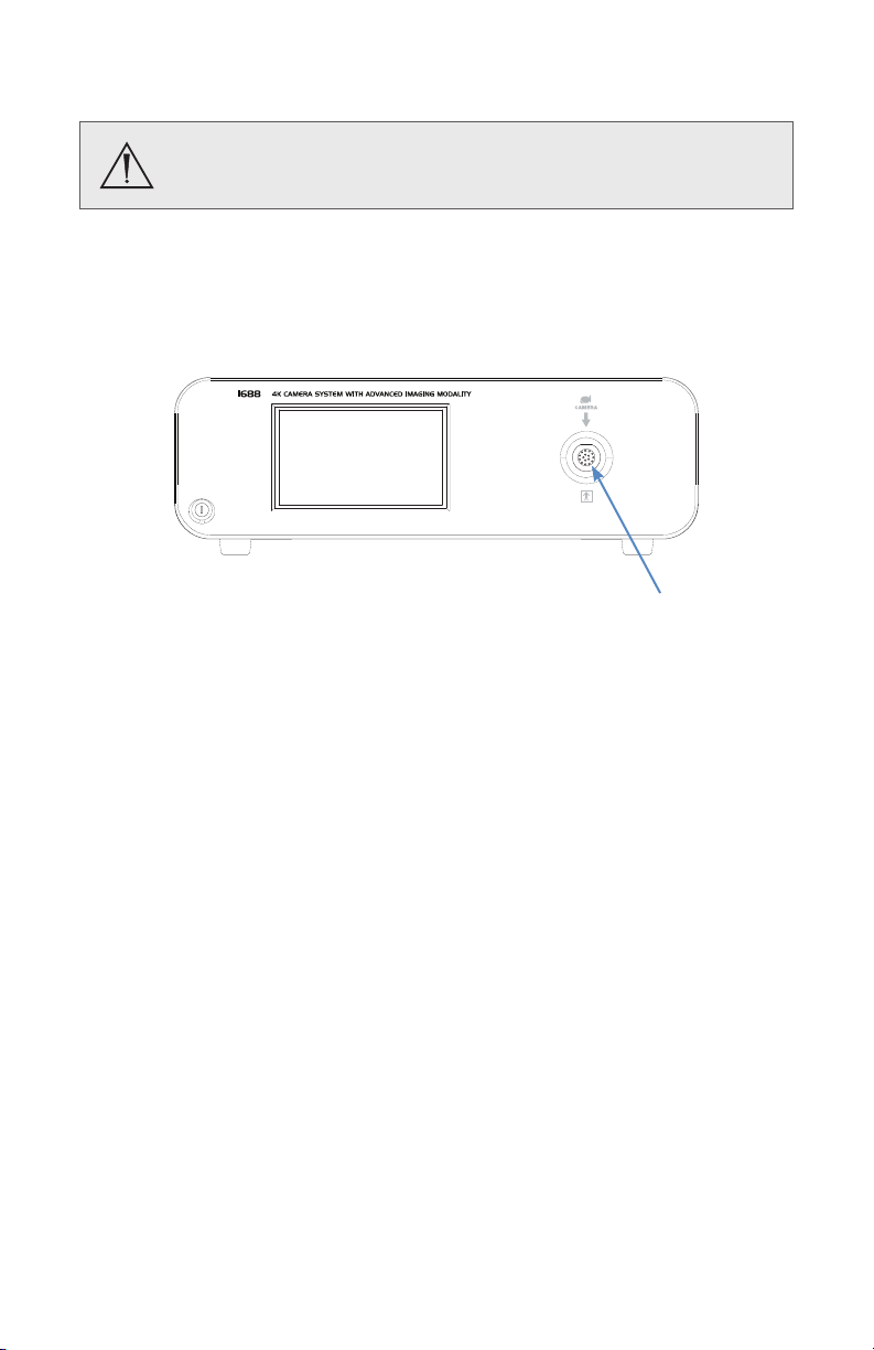
Setting Up the Camera Head
Do not severely bend the camera cable or damage may result.
1. Unscrew the soaking cap from the cable connector on the camera head.
2. Align the arrow on the cable connector with the arrow above the cameraconnector port on the front console panel.
3. Push in the connector until it locks in place.
Note: To unplug the camera from the console, grasp the knobbed portion of
the connector and pull straight out.
19
Page 24

Setting Up the Coupler
Steps 1–3 below provide instructions for connecting 1688 Camera Heads to
the 4K Coupler, C-Mount, with Advanced Imaging Modality (1688-020-122)
and to an endoscope and a light cable. Refer to the bullets below for possible
system variations:
• When using the 1688 4K Pendulum Camera Head with Integrated
Coupler (1688310130) or the 1688 4K Camera Head, Integrated
Coupler, with Advanced Imaging Modality (1688610122), skip to
step 2.
• When using a direct-coupled C-Mount endoscope (an endoscope
that requires no coupler), thread the endoscope directly into the
camera head until it forms a tight seal, and skip to step 3. (C-Mount
endoscopes are not compatible with camera heads that have an
integrated coupler.)
When attaching or removing the coupler, grip only the rear
adapter, as twisting other parts of the coupler with force may
result in mechanical damage.
Do not overtighten the coupler (or a direct-coupled C-mount
endoscope), as this may damage the front window of the
camera.
1. Attach the coupler to the camera head.
• Gripping the rear adapter, screw the coupler clockwise onto the
camera head until it forms a tight seal (1688210105 and 1688710105
only).
Note: To remove the coupler, grip the rear adapter and unscrew the
coupler counterclockwise from the camera head.
20
Page 25

2. Attach an endoscope to the coupler.
Before each use, check the outer surface of the endoscope to
ensure there are no rough surfaces, sharp edges, or protrusions.
For 1688210105, 1688610122, and 1688710105:
Note: For a list of endoscopes that are compatible with SPY mode,
see the user manual for the L11 LED Light Source.
1
2
• Depress the endobody clamp 1 and insert an endoscope into
the endobody
2
.
• Release the endobody clamp to secure the endoscope.
For 1688310130:
3
2
3
• Lock the endobody brake 1 by rotating it clockwise (when
facing the camera head buttons).
• Twist the endobody clamp 2 as shown, and hold it open.
• Insert the endoscope into the endobody clamp.
• Release the endobody clamp. It will return to the original
position and hold the endoscope.
• If the endoscope is not secured in a xed position, slightly
rotate the endobody clamp in either direction until the lock
engages with an audible click.
3. Attach a light cable from the light source to the light post on the
endoscope 3 .
1
21
Page 26
Note: A scope adapter may be required to connect the cable to the
endoscope. See the light cable user manual for more detail.
Note: Only the Stryker AIM SafeLight cable (0233-050-300) is compatible
with SPY mode. SPY mode will not function if other cables are used. Refer
to the AIM SafeLight cable user manual for complete cable instructions.
When connecting an AIM SafeLight cable to the
endoscope, always connect the scope adapter to the
endoscope before connecting the adapter to the cable.
If SPY mode is on and the adapter is not connected to the
scope, laser radiation will emit from the adapter that can
cause severe eye injury to the patient or user.
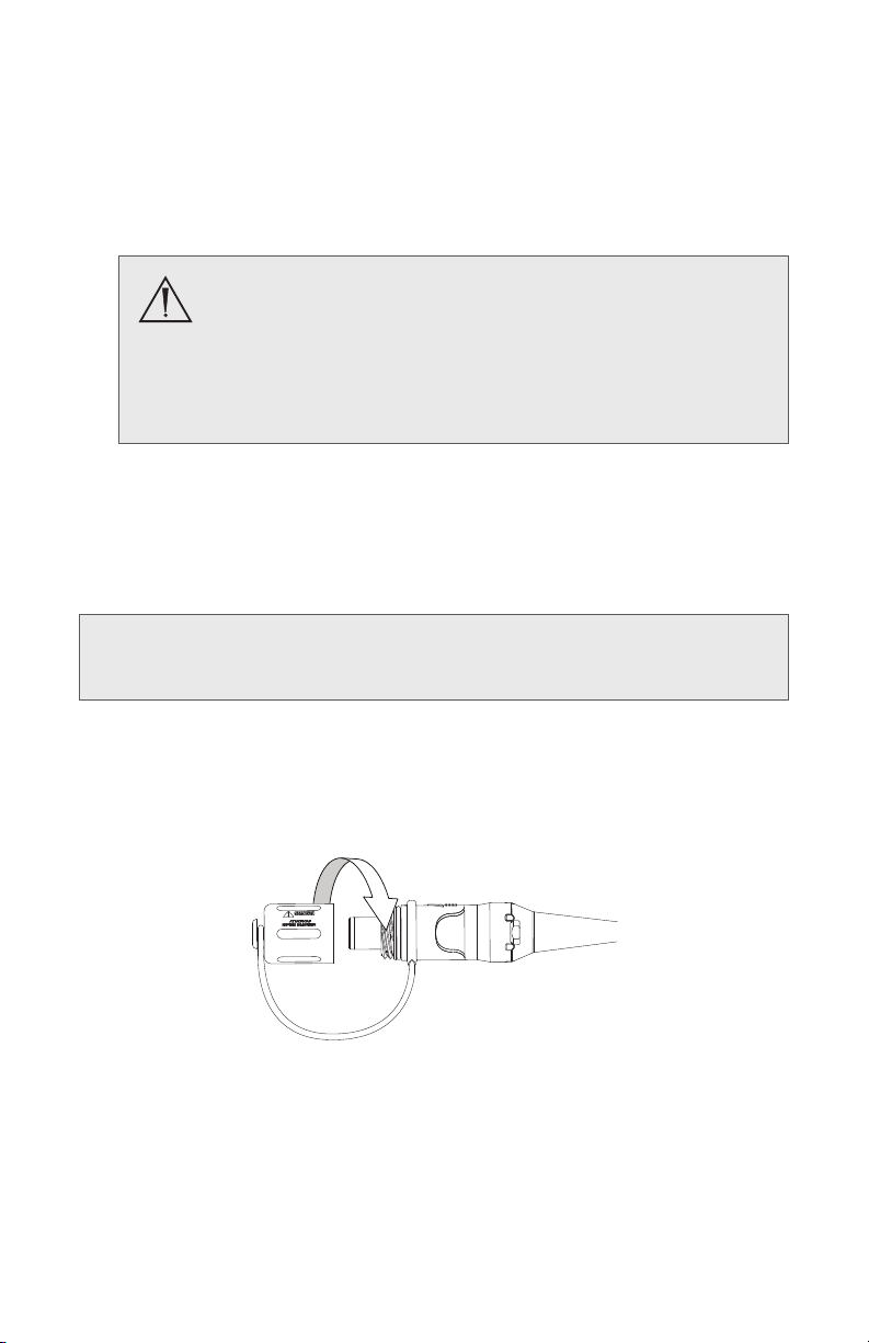
Installing the Soaking Cap
Before reprocessing the camera head, the soaking cap must be installed to
avoid damaging the cable connector.
Caution: Failure to properly tighten the soaking cap will corrode the
connector pins and void the warranty.
• To install the soaking cap, screw the cap onto the threads of the cable
connector until it forms a tight seal.
• To remove the soaking cap, unscrew the cap and pull it away from the
cable connector.
22
Page 27

SPY Mode Requirements
In SPY mode, the camera can visualize near-infrared light produced by the L11
LED Light Source (0220230300).
Before using SPY mode, be familiar with the Warnings: SPY
Mode section of this user manual and all warnings and
instructions in the light source user manual. Failure to follow
all warnings can result in severe eye injury to the patient or
user.
Note: For complete hardware and equipment requirements to use SPY mode,
see the L11 LED Light Source user manual.
SPY mode will function properly on the 1688 Video Camera when the
following conditions are met:
• A 1688 Camera Head is connected to the camera console (must be
model 1688210105, 1688610122, or 1688710105)
• The Laparoscopy or Standard surgical specialty is selected on the
camera console
• The camera console is connected to the L11 LED Light Source (using a
USB 3.0 A-to-B cable provided with the light source)
• The light source is connected to an AIM SafeLight cable (0233-050-
300)
• A SafeLight scope adapter is connected to the SafeLight cable (see the
cable user manual for compatible adapter part numbers)
• Light output is activated from the light source
• Neither the White Balance screen or the camera head button
conguration screen are present on the display monitor
Controls for SPY mode are accessible via the light source or the camera
console touchscreen and camera head buttons. See the light source user
manual or the Operation section of this user manual for more detail.
23
Page 28
Operation
Note: Before operating the device, ensure all system components have been
set up according to the instructions in the Setup section.
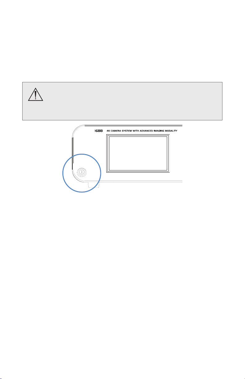
Powering the Console On/O
Before using the camera in a surgical procedure, test all system
components to ensure proper function. Ensure that a video
image appears on all display monitors before beginning any
procedure.
1. Power on the display monitor.
2. Press the power switch on the console to power the console on or o.
Note: A color bar pattern will appear on the display monitor if the camera
head is not connected to the camera console. If the color bar appears, refer to
the Setting Up the Camera Head section to connect the camera head.
Performing the White Balance Test
Before each surgical procedure, perform the White Balance test to adjust the
camera’s perception of white so it can display other colors correctly.
When a camera head is connected to the console and the console is powered
on, the display monitor will automatically prompt the user to perform the
White Balance test.1 Using the camera head buttons, follow the instructions
on the display monitor to perform the test.
1
English must be selected as the language in the Advanced Settings.
The White Balance test can also be performed after the camera head is already
connected by pressing the WB button on the Home screen of the console (or
a camera head button if it has been programmed for White Balance).
24
Page 29

Follow the instructions below to perform the White Balance test:
1. Ensure that a scope, camera head, light source, and display monitor are
connected to the camera system, and that the camera console, light
source and display monitor are powered on.
2. Point the scope tip at several stacked white gauze pads, a white
laparoscopic sponge, or any clean white surface.
3. Look at the display monitor and make sure there is no visible glare o of
the white surface of the image.
4. Press the WB button on the Home screen (or press and quickly release a
camera head button, if it has been programmed for White Balance) until
“WHITE BALANCE IN PROGRESS” appears on the display monitor.
5. Continue pointing the scope at the white surface until “WHITE BALANCE
COMPLETE” appears on the display monitor. The image may change color.
If you cannot achieve an acceptable White Balance, refer to the
Troubleshooting section.
Note: The White Balance test is not available when SPY mode is on.
Controlling Remote Video Accessories
When connected with the provided remote cables, the camera can remotely
control up to two functions of a video accessory such as a Stryker digital
capture console. Commonly this enables the user to capture images or start
and stop video recording.
Remote video accessories can be controlled with the camera head’s Camera
button or the console touchscreen. See the following sections, Using the
Touchscreen Interface and Using the Camera Head Buttons.
See the Setup section for instructions about connecting a video accessory to
the console’s Remote outputs.
25
Page 30

Using the Touchscreen Interface
The touchscreen interface on the console provides access to menus and
controls for adjusting or capturing the video image. The features are
described below.
Navigation Bar
The Navigation Bar appears on the left side of each screen described in this
Operation section. The currently selected screen is highlighted with a blue
line in the Navigation Bar.
Home: Press the Home button to navigate to the Home
screen.
AIM: Press the AIM button to navigate to the SPY screen.
Settings: Press the Settings button to navigate to the
Camera Settings screen.
Auto Light button
The Auto Light button appears in the bottom-right corner of each screen
described in this Operation section. Press the button to toggle Auto Light on
or o.
Note: To enable the Auto Light feature, the camera must be connected to the
L11 LED Light Source and SPY mode must be o. Turning on SPY mode will
disable the Auto Light feature.
On (blue button): Automatic adjustment of light settings
on the light source to meet optimal light output.
O (black button): Auto Light feature is o
26
Page 31

Home Screen
The Home Screen is the default screen. It displays the current surgical
specialty and it provides access to common camera functions.
2
1. Surgical Specialty: Use the arrows to scroll through surgical specialties
that optimize camera performance for specic surgical procedures.
Choose from:
• Arthroscopy
• Cystoscopy
• ENT/Skull
• Flexi-Scope
1
• Laparoscopy
• Laser
• Microscope
• Standard
• Hysteroscopy
1
When Flexi-Scope is selected, the
following icon will appear in the
top-left corner of the display monitor:
2. White Balance: Press and briey hold the WB button to activate the
White Balance test. See the Performing the White Balance Test section for
more detail.
A checkmark appears on the button after White Balance is completed
ü
successfully.
3. Picture: Press the camera button to capture a photo.
A single beep will sound to indicate that a signal for capture/record
ü
has been sent to the digital capture console.
4. Record: Press the record button to record a video. Press again to stop
recording.
A double beep will sound to indicate that a signal for capture/record
ü
has been sent to the digital capture console.
27
Page 32

SPY Screen
SPY mode allows the camera to visualize near-infrared light produced by the
L11 LED Light Source (0220230300). The SPY screen allows the user to adjust
image settings within SPY mode.
Note: White Light must be activated on the L11 LED Light Source as a
preliminary step to activate SPY mode.
See the SPY Mode Requirements section for required equipment and
conditions to enable SPY mode.
2
Before using SPY mode, be familiar with the Warnings: SPY
Mode section of this user manual and all warnings and
instructions in the light source user manual. Failure to follow all
warnings can result in severe eye injury to the patient or user.
1. SPY Mode selection: Press and briey hold the arrows to scroll through
the following SPY modes. The icon shown next to each SPY mode appears
in the top-left corner of the display monitor when the mode is active.
• Overlay: The console outputs a white light image
with ICG uorescence indicated by the color green.
(red, green, and blue)
• Contrast: The console outputs an image with ICG
uorescence indicated by the color white. All other
(all grey)
areas of the image appear dark.
• ENV: The console outputs a greyscale white light
image with ICG uorescence indicated by the color
(all green)
green.
28
Page 33
2. Gain: Press the plus or minus button to increase or decrease the SPY
Gain level, which aects the uorescing green appearance of the camera
image. Range: 1-10.
3. Brightness: Press the plus or minus button to increase or decrease the
brightness appearance of the white light image in SPY mode. Range: 1-8.
4. SPY Mode On/O: Press and briey hold the button to toggle SPY mode
on or o.
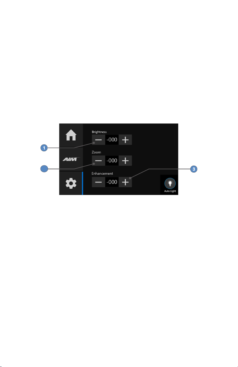
Camera Settings Screen
The Camera Settings screen provides options for adjusting the camera
picture.
2
1. Brightness: Press the plus or minus button to increase or decrease the
brightness level. Range: 1-8.
2. Zoom: Press the plus or minus button to increase or decrease the level of
magnication. Range: 1-7.1
Note: As the Zoom level changes, the camera will optimize the image by
automatically adjusting the Enhancement level.
1
3. Enhancement: Press the plus or minus button to increase or decrease the
enhancement level (the apparent sharpness of the image). Range: 1-8.
1
Information provided is for software version 3.0.7 and higher. In previous software versions, the Zoom range is 1–5 and
the camera does not automatically adjust Enhancement. The software version appears on the boot up screen, or the user
can check by following these steps:
1. On the console Home screen, hold down the Settings button for about 5 seconds until the Advanced Settings
screen appears.
2. Press the System button.
3. Check the CCU version.
4. Click X in the top-right corner to return to the Home screen.
29
Page 34
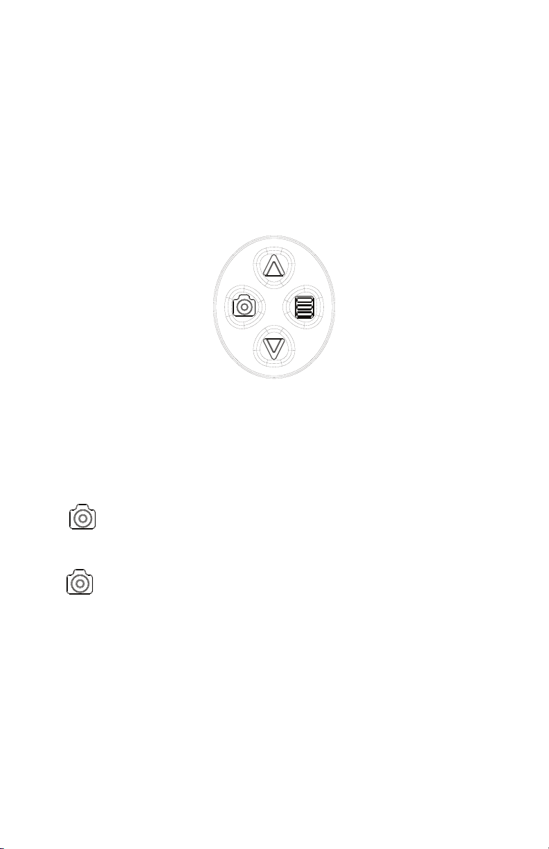
Using the Camera Head Buttons
The camera head features a four-button keypad for controlling the device.
The default button functions are described below.
The camera head buttons can be customized dierently for each surgical
specialty. See the Programming Camera Head Buttons section for more detail.
The button conguration for the selected surgical specialty will appear on
the display monitor when the camera head is connected to the console. The
button conguration will disappear once any camera head button is pressed.
Camera Button
The Camera button controls up to two functions of a remote video accessory.
Commonly this enables the user to capture images or start and stop video
recording. (See the Controlling Remote Video Accessories section for
connection requirements.)
• Short press: Capture Photo. Press and quickly release the Camera
button to select Remote 1. One beep will sound. When the camera is
connected to a Stryker digital capture console, this will capture a photo.
• Long press: Start/Stop Video Recording. Press and briey hold
the Camera button to select Remote 2. Two beeps will sound. When the
camera is connected to a Stryker digital capture console, this will start or
stop video recording.
30
Page 35

Menu Button
The Menu button opens a display monitor menu with options for device
control1, or (depending on the selected surgical specialty) it cycles through
zoom levels or toggles SPY mode on and o.
• Short press: Zoom Cycle (in all surgical specialties except
Laparoscopy and Standard). Press and quickly release the Menu button
to Increase the Zoom level. When the maximum Zoom level is reached,
pressing the button again cycles to the minimum level.
• Short press: SPY Toggle (in Laparoscopy or Standard surgical
specialty). Press and quickly release the Menu button to turn SPY mode on
and o.
• Long press: Open Menu. Press and briey hold the Menu button
to open a Menu on the display monitor with image settings and device
control options.1 See the Display Monitor Menu section for detail.
1
English must be selected as the language in the Advanced Settings.
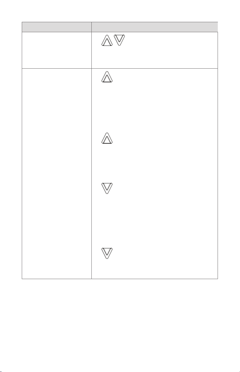
Up and Down Buttons
The up and down buttons change functionality depending on the conditions:
Conditions Functionality of Up/Down buttons
• Default
• Short press: Brightness Level.
Press and quickly release the up and
down buttons to increase or decrease the
brightness level in eight steps.
• Long press: Lightsource Toggle. Press
and briey hold the up button to toggle
the light source between activating and
decativating light output.
• Long press: Hub Function. Press
and briey hold the down button to signal
the device control console to perform an
assignable command.
31
Page 36
Conditions Functionality of Up/Down buttons
• English selected as
language
• Menu is open on the
display monitor
• SPY mode is on
• Scroll list. Press the up and down
buttons to scroll up and down the list on the
display monitor.
• Short press: SPY Image Cycle. Press
and quickly release the up button to activate
the SPY Image Cycle function, which cycles
through the SPY modes (Overlay, Contrast,
and ENV). SPY mode must be turned on for
Overlay, Contrast, or ENV mode to aect the
video image.
• Long press: Brightness Cycle. Press
and briey hold the up button to activate the
Brightness Cycle function. Each press raises
the brightness level in eight steps; pressing
it again cycles the level back to the lowest
setting.
• Short press: SPY Gain Cycle. Press and
quickly release the down button to activate
the SPY Gain Cycle function, which uses the
camera processor to adjust the uorescing
appearance of the camera image. Each
press raises the SPY Gain level in eight steps;
pressing it again cycles the level back to the
lowest setting.
32
• Long press: No function. Pressing
and briey holding the down button in SPY
mode has no function.
Page 37

Using the Display Monitor Menu
Press and briey hold the Menu button to open a series of menus on the
display monitor with image settings and device control options.1 The menus
are described below.
1
English must be selected as the language in the Advanced Settings.
While the Menu feature is open, the camera head buttons will change
function to navigate the menus and lists on the display monitor.
• The up and down buttons scroll up and down the list of options.
• The Menu button selects the highlighted option.
• The Camera button returns to the previous menu. At the top-level
menu, pressing the Camera button again exits the Menu feature.
Some menu options will not be available if the console is not connected to
the L11 LED Light Source. The options that are not available appear in grey.
When the console is connected to the Devices input on the Connected OR
Hub, more options for device control will appear in the menus. Refer to the
Connected OR Hub user manual for information about the additional options.
Top-Level Menu Description
IMAGING MODES Navigate to Imaging Modes menu
CAMERA SETTINGS Navigate to Camera Settings menu
WHITE BALANCE Start White Balance test
Imaging Modes
Description
Menu
SPY Navigate to SPY menu
AUTOLIGHT Navigate to Auto Light menu
IRIS Navigate to IRIS menu
Camera Settings
Description
Menu
LIGHT SOURCE Navigate to Light Source menu
ZOOM IN Increase zoom level
ZOOM OUT Decrease zoom level
SHUTTER AUTO Sets the shutter to automatically adjust to the
desired brightness without overexposing the image
33
Page 38

SHUTTER MANUAL Turns o automatic shutter (overall, image is more
overexposed)
BRIGHTER Increase brightness level
DARKER Decrease brightness level
SPY Menu Description
ON Turn on SPY mode, which allows the camera to
visualize near-infrared light
OFF Turn o SPY mode
MODE Navigate to SPY Mode menu
GAIN UP Increase SPY Gain level, which uses the camera
processor to adjust the uorescing appearance of
the camera image
GAIN DOWN Decrease SPY Gain level, which uses the camera
processor to adjust the uorescing appearance of
the camera image
BACKLIGHT UP Increase Backlight level, which aects the brightness
of surrounding anatomy in the camera image that
is not displayed as uorescing green (available only
when used with the L10 LED Light Source)
BACKLIGHT DOWN Decrease Backlight level, which aects the
brightness of surrounding anatomy in the camera
image that is not displayed as uorescing green
(available only when used with the L10 LED Light
Source)
Auto Light Menu Description
ON Turn on the Auto Light feature, which automatically
adjusts light settings on the light source to meet
optimal light output.
OFF Turn o the Auto Light feature
34
Page 39

IRIS Menu Description
ON Turn on Infrared Illumination System (IRIS) mode
on the light source, which enables use of the IRIS
Ureteral Kit when connected to a compatible light
source
OFF Turn o IRIS mode
CONTINUOUS Set the IRIS light output to continuous (the laser
energy is continuous)
PULSATING Set the IRIS light output to pulsating (the laser
energy pulses in a repeating pattern of 0.5 second
on/0.5 second o (1 pulse cycle/second)
SPY Mode Menu Description
OVERLAY Change the SPY mode to Overlay (the console
outputs a white light image with ICG uorescence
indicated by the color green)
CONTRAST Change the SPY mode to Contrast (the console
outputs an image with ICG uorescence indicated
by the color white; all other areas of the image
appear dark)
ENV Change the SPY mode to ENV (the console outputs
a greyscale white light image with ICG uorescence
indicated by the color green)
Light Source Menu Description
ACTIVATE Turn on white light from the light source
STANDBY Deactivate light output from the light source
LIGHT UP Increase the white light brightness on the light
source
LIGHT DOWN Decrease the white light brightness on the light
source
AUTOLIGHT ON Turn on the Auto Light feature, which automatically
adjusts light settings on the light source to meet
optimal light output.
AUTOLIGHT OFF Turn o the Auto Light feature
35
Page 40

Programming Camera Head Buttons
The camera head buttons can be customized dierently for each surgical
specialty. Contact a Stryker representative for assistance with button
programming.
The button conguration for the selected surgical speciality will appear on
the display monitor when the camera head is connected to the console. The
button conguration will disappear once the Camera button is pressed.
Note: The default up and down camera head button functions when SPY
mode is on cannot be recongured.
The following functions can be programmed to the buttons:
Function Name Function Description
AUTO LIGHT TOGGLE Toggle the Auto Light function on/o
BACKLIGHT UP Increase Backlight level, which aects the brightness
of surrounding anatomy in the camera image that is
not displayed as uorescing green
BACKLIGHT DOWN Decrease Backlight level
BACKLIGHT CYCLE Increase Backlight level until maximum level, then
cycle back to minimum level
BRIGHTNESS UP Increase brightness level
BRIGHTNESS DOWN Decrease brightness level
BRIGHTNESS CYCLE Increase brightness until maximum level, then cycle
back to minimum level
ENHANCE UP Increase enhance level, which sharpens the camera
image
ENHANCE DOWN Decrease enhance level
ENHANCE CYCLE Increase enhance until maximum level, then cycle
back to minimum level
HUB FUNCTION Signal the device control console to perform an
assignable command
LIGHT SOURCE
TOGGLE
MENU OPEN Open the menu with device control options
NO FUNCTION No function
PICTURE Activate picture function on digital capture console
Toggle the light source between activating and
deactivating light output
(activate Remote1 cable)
36
Page 41

Function Name Function Description
RECORD Activate record function on digital capture console
(activate Remote2 cable)
SPY GAIN UP Increase SPY Gain level, which uses the camera
processor to adjust the uorescing appearance of
the camera image
SPY GAIN DOWN Decrease SPY Gain level
SPY GAIN CYCLE Increase SPY Gain until maximum level, then cycle
back to minimum level
SPY IMAGE CYCLE Cycle through the SPY modes (Overlay, Contrast,
and ENV). SPY mode must be turned on for Overlay,
Contrast, or ENV mode to aect the video image.
SPY TOGGLE Toggle SPY mode on/o
WHITE BALANCE Start White Balance test
ZOOM IN Increase zoom level
ZOOM OUT Decrease zoom level
ZOOM CYCLE Increase zoom until maximum level, then cycle back
to minimum level
Advanced Features
The 1688 Video Camera has additional features that are not detailed in this
manual:
• Button programming
• Video image settings
• Language settings
• Light source Run/Standby controls
• Other system settings
These advanced features require in-depth knowledge of the device and should
be performed only by trained personnel. For access to advanced features,
contact a Stryker representative.
37
Page 42

Troubleshooting
Problem Possible Solution
E-01 error code (“Video
Error”)
E-02 error code
(“Console Overheating”
warning)
E-03 error code
(“Software Mismatch”)
E-04 error code (“Error
Occurred”)
E-04 error code
(“Warning Occurred”)
E-05 error code
(“Unauthorized
Component” warning)
Touchscreen freezes • Turn o the console, wait 3 seconds, and turn
• Turn o the console, wait 3 seconds, and turn
it back on.
• Contact Stryker if the problem persists.
• Ensure console is in a ventilated area.
• Turn o the console, wait 3 seconds, and turn
it back on.
• Contact Stryker if the problem persists.
• Turn o the console, wait 3 seconds, and turn
it back on.
• Return the device to Stryker for service if the
problem persists.
• Turn o the console, wait 3 seconds, and turn
it back on.
• Contact Stryker if the problem persists.
• Turn o the console, wait 3 seconds, and turn
it back on.
• Contact Stryker if the problem persists.
• Return the camera head to Stryker for
service.
Warning: This error indicates an
unauthorized component is detected within
the camera head (including its cable),
which voids the warranty. The functional
performance and quality of the device may
be impacted.
it back on.
“Restart Camera
Console” message
(Color bar background)
38
• Turn o the console, wait 3 seconds, and turn
it back on.
• After sterilization, ensure the camera head
has cooled down before connecting it to the
console.
Page 43

Problem Possible Solution
“System Error”
message (Light blue
background)
No color bar • Ensure the video-out from the console is
Incorrect picture color • Perform the White Balance test. (See the
White Balance quality
is not good
“White Balance Fail”
message on display
monitor
Picture is too dark • Increase the camera Brightness level.
• No video detected.
• After sterilization, ensure the camera head
has cooled down before connecting it to the
console.
• Return the system for repair.
connected to the video-in on the display
monitor.
• Ensure all video systems are powered on.
• Ensure that the camera head is not
connected to the console.
• Turn o the console, wait 3 seconds, and turn
it back on.
Performing the White Balance Test section.)
• Check the color settings on the display
monitor.
• See the solution for Picture is too dark.
• See the solution for Picture is too bright.
• Perform the White Balance test with the light
source connected to the scope. Use metalhalide, xenon, or LED lighting (no uorescent
lighting).
• Using the camera head, click the Start
button on the display monitor to repeat the
White Balance test. Ensure there is sucient
light and the camera head is pointing at
something white.
• Using the camera head, click the Skip button
to accept the current White Balance settings.
• Increase the light source output.
• Check the beroptic light cable for excessive
broken bers.
Picture is too bright • Decrease the camera Brightness level.
• Decrease the light source output.
39
Page 44

Problem Possible Solution
Noise or snow on
picture when using
electrocautery probes
Noise or snow on
picture when not using
electrocautery probes
No video picture when
the camera head is
plugged in
Image is not well
centered
Variability in color
reproduction between
dierent light sources
or peripherals
Foggy picture (loss of
denition and clarity)
• Plug the electrocautery generator into
a separate electrical outlet and separate
the camera console power cord from the
electrocautery power cord.
• Separate the camera cable from the
electrocautery cable.
• Reposition the electrocautery grounding pad
on the patient.
• Conrm all cable connectors are securely
attached.
• Check for and replace faulty video cables.
• Check to ensure that all devices in the video
system are plugged in and powered on.
• Check the connector on the camera-head
cable for broken pins.
• Detach the camera head from the console
and reconnect.
• Turn o the console, wait 3 seconds, and turn
it back on.
• Release the scope from the coupler and then
reconnect it. Make sure the scope is seated
correctly in the coupler.
• Perform the White Balance test. (See the
Performing the White Balance Test section.)
• Check the settings on video peripherals.
• Ensure the light source has a proper
infrared lter (check with manufacturer
specications).
• Refocus the coupler.
• Disassemble the scope, coupler, and camera
head, and clean and dry all windows on the
components.
40
Page 45

Problem Possible Solution
Optics are dirty • Rotate the scope. If dust particles in the
picture rotate, the dust is located on the
scope itself. Follow the manufacturer’s
instructions for cleaning the eyepiece and
negative lens.
• If particles in the picture do not move
when you rotate the scope, the particles are
located on the coupler or camera. Remove
the scope and clean the window on the front
of the coupler with a dry or alcohol-tipped
cotton swab.
• Disassemble the scope, coupler, and camera
head, and clean and dry all windows on the
components.
• Ensure all components are completely dry
before reassembling them, or fogging may
result.
Blurry picture • Ensure the coupler or C-mount scope is in
focus.
• On the Home screen, ensure the surgical
specialty is not set to FLEXI-SCOPE unless you
are using a exible scope.
• Disassemble the scope, coupler, and camera
head, and clean and dry all windows on the
components.
SIDNE device does not
recognize camera head
SPY mode won’t turn on• Conrm the requirements in the SPY Mode
Visual artifacts
observed when Auto
Light is on
• Contact your Stryker representative for
compatibility settings.
Requirements section have been met.
• Turn o Auto Light from the camera, and
manually reduce the brightness from the
light source.
Note: If this Troubleshooting section does not resolve the problem, call
Stryker Technical Support at 1-877-478-7953 (inside the U.S.) or refer to the
warranty.
41
Page 46

Reprocessing
The camera console is not intended to come into contact with the patient. It
may be cleaned, but not sterilized. Follow the instructions below.
Camera heads 1688210105, 1688310130, 1688610122, and 1688710105 are
used in the sterile eld and shall be cleaned and sterilized prior to every use.
Follow the instructions below.
The 1688 4K Microscope Camera Head (1688210080) must not be sterilized or
immersed in water. It may be used in the sterile eld only with proper sterile
technique. See user manual P45082 for complete instructions.
The coupler is used in the sterile eld and shall be cleaned and sterilized prior
to every use. For 4K Coupler (1688-020-122) reprocessing instructions, see
user manual P40880.
Cleaning and Disinfecting the Console
Follow the warnings, cautions, and instructions below to clean and disinfect
the console. The user shall provide the germicidal disposable wipes (or
germidical spray and sterile cloth).
To avoid electric shock and potentially fatal injury, disconnect
the console from the AC power source before cleaning.
Observe the following cautions to avoid damaging the
console:
• Do not sterilize the console.
• Do not immerse the console in any liquid.
• Do not allow liquid to drip onto the console or collect on
any of its surfaces. Use extra care to prevent liquid from
dripping or pooling on the bottom of the LCD screen.
• Do not spray cleaning liquid directly onto the console,
power buttons, or connectors. Spray the cleaning liquid
onto a cloth, and use the cloth to wipe the console. Do not
saturate the cloth.
• Do not clean the console with abrasive products or
corrosive cleaning solutions.
1. Clean and disinfect the console using a germicidal disposable wipe1 (or
equivalent combination or germicidal spray and sterile cloth) according
to the manufacturer’s instructions.
42
Page 47

2. Visually inspect the external surface of the device for cleanliness, focusing
on hard-to-reach areas. If visible soil remains, repeat cleaning and
disinfection until all visible soil is removed.
1
Cleaning and disinfection were validated using PDI® Super Sani-Cloth® Germicidal Disposable Wipes.
Cleaning, Disinfecting, and Sterilizing the Camera Head
These reprocessing instructions are provided in accordance with
ISO17664, ISO15883, AAMITIR12, and AAMITIR30. The instructions
have been validated by Stryker as being capable of preparing the device
for re-use. To achieve the desired result, the processor shall ensure that
the following instructions are performed as written in their entirety and
as appropriate in the processor’s facility. This normally requires routine
monitoring and validation of the facility’s reprocessing procedures. Stryker
recommends users observe these standards when reprocessing medical
devices.
Overview
Reprocessing the device involves manual or automated cleaning with
either an enzymatic or a non-enzymatic detergent, optional disinfection,
and sterilization.
• Step 1 (required): Cleaning with Enzymatic or Non-Enzymatic
Detergent
• Step 2 (optional): Disinfection
• Step 3 (required): Sterilization
Warnings
• This device must be cleaned and sterilized prior to the rst use and after
every subsequent use.
• Separate the camera head, coupler (when used with 1688210105 and
1688710105 only), and endoscope prior to cleaning, disinfection, or
sterilization. Failure to follow this instruction will render the devices
non-sterile. (Refer to the coupler and endoscope product manuals for
reprocessing instructions for those devices.)
• Wear appropriate protective equipment: gloves, eye protection, etc.
• To avoid health risks from aerosol contamination, brush the device only
when it is submerged in liquid.
• Use only the sterilization cycles outlined in this document. Using
unspecied sterilization cycles may damage the device or result in
incomplete sterilization.
• The sterilization parameters presented in this document apply only
when the device is sterilized outside of a sterilization tray. When using a
43
Page 48

sterilization tray, consult the instructions provided with the tray for proper
sterilization parameters. Stryker recommends sterilizing the device inside
of a sterilization tray.
• Sterilize only one camera head per tray, or incomplete sterilization may
result. Follow any instructions provided with the sterilization tray or system
regarding tray setup and other devices that may be sterilized within the
same tray.
• Devices repaired by or purchased from third-party service organizations
could expose patients to signicant risk. These devices are no longer
validated by Stryker for cleanliness, disinfection, and sterilization, or for
safety and ecacy.
• The user shall defer to the facility’s procedures regarding occupational
exposure to bloodborne pathogens.
Cautions
• Always install the soaking cap prior to processing the camera. Failure to
properly tighten the soaking cap will corrode the connector pins and void
the warranty. Refer to the Installing the Soaking Cap section for more detail
about installing the cap.
• Inspect the camera cable for cuts and breaks before soaking in any uid.
Return any damaged camera to Stryker for service.
• Never store the camera in the same tray with sharp instruments. Do not
soak the camera while it is inside a tray.
• Do not use brushes or pads with metal or abrasive tips during manual
cleaning, as permanent scoring or damage could result.
• To minimize galvanic corrosion, avoid soaking dissimilar metals in close
proximity.
• The device cannot withstand an automated disinfection method.
• The 1688 camera heads are not autoclavable. Steam sterilizing camera
heads that are not marked AUTOCLAVE will result in product damage.
• Allow the camera head to cool before connecting it to the console.
Connecting the camera head while it is hot may result in system error.
Limitations on Reprocessing
• Do not cross-sterilize the device. Using multiple sterilization methods may
signicantly reduce the performance of the device.
• Repeated automated cleaning can degrade the product’s cosmetic
appearance.
• Damage caused by improper processing is not covered by the warranty.
44
Page 49

Materials and Equipment
All materials and equipment required to reprocess the camera head shall be
supplied by the user unless otherwise noted.
Item Description
All phases
Gloves, eye protection,
etc.
Cleaning
Wash basin Large enough to accommodate camera head without
Lukewarm water To prepare cleaning solutions
Detergent
Soft-bristle brush
Reverse osmosis/
deionized water
1
2
3
Clean cloth or ltered
pressurized air (≤40 psi)
Automated washer For using the automated cleaning procedure
Disinfection
Wash basin Large enough to accommodate camera head without
Disinfecting solution
Water To prepare disinfecting solution
Reverse osmosis/
deionized water
3
Clean cloth or ltered
pressurized air (≤40 psi)
Sterilization
Sterilization system · Sterrad® 100S, NX®, 100NX®, NX AllClear®, or 100NX
Sterilization wrap
Sterilization tray
5,6
6,7
Wear protective equipment as required by the medical
facility and procedure.
excessive bending of cable
Used in cleaning solution to remove surgical debris
To clean exterior of device or hard-to-reach areas of
device
To rinse device
To assist with drying
excessive bending of cable
4
≥ 2.4% glutaraldehyde
To rinse the device
To assist with drying
AllClear
· Steris/Amsco® V-PRO® 1, V-PRO 1 Plus, V-PRO maX,
V-PRO maX 2, or V-PRO 60
To maintain sterile barrier
Optional. Must be compatible with sterilization method.
45
Page 50

1
The following detergents were validated for cleaning ecacy according to the manufacturer’s instructions. Choose one of the
detergents listed below or a substantially equivalent detergent:
Detergent Type Minimum Concentration Minimum Soak
ENZOL® Enzymatic Detergent Enzymatic 1 oz/gallon 1 minute
Prolystica® 2x Neutral Detergent Non- enzymatic 1/8 oz/gallon (1 ml/L) 5 minutes
Neodisher® MediClean Forte Enzymatic 5/8 oz/gallon (5 ml/L) 5 minutes
2
Cleaning was validated with an M16 soft-bristle brush.
3
Rinsing the device during cleaning and disinfection was validated using reverse osmosis/deionized (RO/DI) water at ≤30°C.
4
Disinfection was validated using CIDEX® Activated at 25 °C with a soaking time of 45 minutes.
5
Sterilization was validated using Halyard Kimguard ONE-STEP sterilization wrap.
6
For United States users: when sterilizing the device, use only sterilization wraps and sterilization trays that have been cleared by
the FDA to use with the selected sterilization cycle.
7
Stryker sterilization trays 0233-032-301, 0233-032-302, 0233-032-105, 0233-032-107, and 0233-410-002 are validated as
compatible with camera heads 1688210105, 1688610122, and 1688710105. The same sterilization trays except for 0233-032-107
are validated as compatible with camera head 1688310130.
Time
Instructions for Reprocessing
Point of Use
• Disassemble the camera head from the coupler (1688210105 and
1688710105 only) and from the endoscope. To disconnect the coupler, grip
the rear adapter of the coupler and unscrew it counterclockwise from the
camera head. To disconnect the endoscope, depress the endobody clamp
on the coupler—or for 1688310130, twist the clamp clockwise when the
buttons are facing you—and remove the endoscope from the coupler.
• Wipe any excess soil from the device.
Containment and Transportation
• Reprocess the device as soon as possible following use.
• Transport the device in a tray to avoid damage. Follow the facility’s internal
procedures for the transportation of contaminated surgical instruments
and devices.
Cleaning
1
Follow the Preparation for Cleaning instructions below.
2
Then clean the device using either the Manual Cleaning or Automated
Cleaning instructions below.
Note: For necessary materials and equipment, see the Materials and
Equipment table.
Preparation for Cleaning
1. Fill a wash basin with lukewarm water.
2. Measure and dispense the desired amount of detergent into the water.
46
Page 51

Note: See the Materials and Equipment table for validated detergents
with their minimum concentration.
3. Gently mix the detergent into the water by hand.
4. Submerge the device into the prepared wash basin.
5. With the device immersed in the solution, thoroughly brush the exterior
with a soft-bristled brush, focusing on any mated or rough surfaces.
6. Actuate and brush any movable parts in all extreme positions.
7. Rinse each device with water until all detergent residue is removed.
8. Once all detergent residue is removed, continue to rinse for 30 seconds.
9. Drain excess water from the device and dry it using a clean cloth or
pressurized air.
10. Visually inspect each device for cleanliness, paying close attention to
hard-to-reach areas. If visible soil remains, repeat steps 1– 10.
Manual Cleaning
1. Prepare a fresh solution of detergent with lukewarm water.
Note: See the Materials and Equipment table for validated detergents
with their minimum concentration and soak time.
2. Wipe the entire surface of the device using a soft clean cloth dipped in
the detergent solution.
3. Immerse the device in the detergent solution, ensuring the solution
contacts all inner and outer surfaces.
4. Soak the device in the solution according to the manufacturer’s
recommendations.
5. With the device immersed in the solution, thoroughly brush the exterior
with a soft-bristle brush, focusing on any mated or rough surfaces.
6. Actuate and brush any movable parts in all extreme positions.
7. Rinse each device with water until all detergent residue is removed.
8. Once all detergent residue is removed, continue to rinse for 30 seconds.
9. Drain excess water from the device and dry it using a clean cloth or
pressurized air.
10. Visually inspect each device for cleanliness, paying close attention to
hard-to-reach areas. If visible soil remains, repeat steps 1– 10.
Automated Cleaning
The device cannot withstand an automated disinfection
method. When programming the washer, do not include a
thermal rinse cycle or the device will be damaged.
47
Page 52

1. Place the device in the automated washer on an incline to facilitate
drainage.
2. Program the washer using the following parameters:
Phase Recirculation
Time
Pre-Wash 2 minutes Cold Water N/A
Wash 1 5 minutes Set Point 60 °C
Rinse 1 2 minutes Hot Water N/A
Dry Phase 2 minutes 115 °C (239 °F) N/A
3. Drain excess water from the device and dry it using a clean cloth or
pressurized air.
4. Visually inspect each device for cleanliness, paying close attention to
hard-to-reach areas. If visible soil remains, repeat steps 1– 4.
High-Level Disinfection (Optional)
The device must be sterilized after disinfection. Failure to
sterilize the device before reuse presents an acute infection
control risk to the patient.
Note: For necessary materials and equipment, see the Materials and
Equipment table.
Temperature Detergent Type
See Materials
(140 °F)
and Equipment
table
The device can be disinfected using a disinfecting solution that has the
following active ingredient: ≥ 2.4% glutaraldehyde.
1. Clean and prepare the device as recommended in this user manual.
Ensure the soaking cap is installed.
2. Prepare the disinfecting solution and verify the minimum eective
concentration according to the manufacturer instructions.
3. Immerse the device in the solution, lling all mated surfaces and crevices.
Ensure air bubbles are removed from the surface of the device.
4. Allow the device to remain in contact with the disinfecting solution
according to the manufacturer’s recommended soak time.
5. Thoroughly rinse and ush the device with running, reverse osmosis/
deionized water to remove the disinfectant.
6. Dry the device with a sterile, lint-free cloth immediately after rinsing.
Filtered pressurized air may be used to assist in drying.
48
Page 53

Sterilization
After performing the cleaning instructions specied above, perform one
of the following sterilization cycles. Note: For necessary materials and
equipment, see the Materials and Equipment table.
Sterrad
1. Clean and prepare the device as recommended in this user manual.
Ensure the soaking cap is installed.
2. If using a sterilization tray (optional), follow any additional instructions
provided with the tray. Use only trays that are compatible with Sterrad.
3. Double wrap the device (or tray) prior to sterilization.
4. Sterilize the device using one of the following Sterrad sterilization
systems:
• 100S (Short or Long1 cycle)
• NX (Standard or Advanced cycle)
• 100NX (Standard or DUO cycle)
• NX AllClear (Standard or Advanced cycle)
• 100NX AllClear (Standard or DUO cycle)
1
Sterrad 100S Long cycle is intended for use outside the U.S. only.
5. Allow the device to cool to room temperature before reconnecting it to
the camera system. Otherwise, the lens can fog during use or the console
can produce a system error.
Steris/Amsco V-PRO
1. Clean and prepare the device as recommended in this user manual.
Ensure the soaking cap is installed.
2. If using a sterilization tray (optional), follow any additional instructions
provided with the tray. Use only trays that are approved for sterilization
with V-PRO.
3. Double wrap the device (or tray) prior to sterilization.
4. Sterilize the device using one of the following V-PRO sterilization systems:
• V-PRO 1 (Standard cycle)
• V-PRO 1 Plus (Non-Lumen or Lumen cycle)
• V-PRO 60 (Non-Lumen, Lumen, or Flexible cycle)
• V-PRO maX (Non-Lumen, Lumen, or Flexible cycle)
• V-PRO maX 2 (Non-Lumen, Lumen, Flexible, or Fast Non-Lumen1 cycle)
1
Warning: When using the Fast Non-Lumen cycle, follow the instructions provided with the V-PRO maX 2 system
regarding use of rigid containers or sterilization wrap. The cycle is intended to be used with sterilization pouches. Also
observe the Fast Non-Lumen cycle weight limit of up to 11 pounds (4.99 kg) of instruments.
5. Allow the device to cool to room temperature before reconnecting it to
the camera system. Otherwise, the lens can fog during use or the console
can produce a system error.
49
Page 54

Maintenance
Follow the instructions in this section for proper care of the device.
Note: Repairs and equipment modications shall be performed only by
Stryker-authorized personnel. Stryker Endoscopy assumes no product liability
or warranty responsibility for devices repaired by or purchased from thirdparty service organizations.
Inspecting the Console
Inspect the console regularly for cleanliness. If the console appears dirty,
repeat the above cleaning and disinfection procedure.
Regularly inspect the lock ring on the front of the console (located at the
camera connection port). Conrm the lock ring is not loose; tighten if
necessary by manually turning the lock ring clockwise.
Inspect the console before each use. If a problem listed below is observed or
suspected, contact your Stryker representative or return the device to Stryker
for service.
• If the console is unresponsive to touchscreen button presses or cannot
power on
• Visible cuts or breaks in any cables
• Unacceptable deterioration such as (but not limited to) corrosion,
discoloration, pitting, cracked seals, or abnormal noises
Inspecting the Camera Head
Inspect all components of the camera head for cleanliness before each use. If
uid or tissue buildup is present, repeat the above cleaning and sterilization
procedures.
Inspect the camera head before each use. If a problem listed below is
observed or suspected, contact your Stryker representative or return the
device to Stryker for service
• If the image output performance of the camera is unacceptable. (For
camera heads 1688210105 and 1688710105, use a coupler that has been
inspected per the coupler user guide.) The camera head shall be able to
provide an image that is clear and focusable with adequate response to
lighting of various scenes.
• If the console is unresponsive to pressing camera head buttons
• Visible cuts or breaks in the camera head cable or keypad area
• Unacceptable deterioration such as corrosion, pitting, cracked seals, or
abnormal noises
50
Page 55

Using Sterile Drapes
Using sterile drapes will ensure maximum longevity of the camera. For best
results, follow the instructions provided by the drape manufacturer.
Storage
Store the device in a dry, clean, and dust-free environment at room
temperatures.
Replacing the Fuses
To avoid the risk of re, use only fuses of the value specied on
the fuse label located on the rear panel of the device.
1. Unplug the power cord from the wall outlet and remove the cord from
the device.
2. Unlatch the fuse holder above the AC inlet and remove it. (You may need
to press the tab on the fuse holder with a slender screwdriver to release
the latch.)
3. Replace the fuse with the same value and rating.
4. Reinstall the fuse holder until the tab snaps in place.
51
Page 56

Periodic Maintenance Schedule
To ensure safe operation of the device, you should
periodically perform the following procedure:
Every 12 months, check the earth leakage current to <500 µA (<300 µA
in USA), ground protective earth impedance to <0.1 ohms, and power
consumption less than or equal to rated power. Use a true RMS digital
multimeter and safety analyzer to perform this test.
Note: Refer calibration and operating diculties not detailed in this manual
to your Stryker representative.
Service Life
The 1688 camera console has an expected service life of 4 years.
The 1688 camera heads have an expected service life of 2 years.
Expected service life is determined by the number of times the device can
be expected to be reused and/or reprocessed before it may require repair. In
addition, the device’s service life is largely determined by wear, reprocessing
methods, and any damage resulting from use. To extend the time between
device servicing, always follow the care and handling instructions in this user
manual.
Before each use, test the device functionality and inspect it for any sign of
damage per the Inspection section. If the device does not properly function
or appears to be damaged, return it to Stryker for evaluation and/or repair.
Repair through Stryker, the equipment manufacturer, brings the device
back to manufacturer specications. Clean and (when applicable) sterilize all
potentially contaminated devices before returning them to Stryker.
Disposal
This product contains electrical waste or electronic equipment.
It must not be disposed of as unsorted municipal waste and
must be collected separately in accordance with applicable
national or institutional related policies relating to obsolete
electronic equipment.
Dispose of the product according to local laws and hospital practices. Refer to
the recycling diagram(s) to identify components that must be recycled.
52
Page 57

Recycling Diagrams
Console
1
2
3
5
4
6
89
Item Material Qty. Comments
1 AC Power Cord 1 Cable length abbreviated in diagram
2 HDMI Cable 1 Cable length abbreviated in diagram
3 Remote Cable 2 Cable length abbreviated in diagram
4 PC Board 2 Behind front panel (not shown in
diagram)
5 PC Board 1 —
6 Power Supply 1 —
7 PC Board 1 —
8 PC Board 1 —
9 PC Board 1 —
7
53
Page 58

Camera Head
Camera head model 1688210105 is shown below to represent features that
are common to each camera head.
1
Item Material Qty. Comments
1 Cable 1 —
Note: In accordance with the European REACH Regulation and other
environmental regulatory requirements, lead metal is present in a
concentration above 0.1% weight by weight (w/w) in some components of
the cable assembly for the 1688 Camera Heads. This declaration is made in
good faith and is based upon supplier data.
54
Page 59

Technical Specications
Imaging System 1/2.8″ Progressive Scan CMOS
Ultra High Denition
Scanning System Horizontal: 135.00 kHz
Vertical: 60.00 Hz
Video Outputs Two HDMI 2.0 outputs
Formats: 1080p (HDTV), 4K UHD (3840 x 2160)
Mounting Endoscope eyepiece used with C-mount coupler
C-mount camera head used with C-mount scopes
(C-mount coupler/scope thread: 1-32″ UN 2A)
Auto Shutter Range 1/60 – 1/22,478 second
Operating Conditions Temperature: 10–30 °C
Relative Humidity: 25–75%
Atmospheric pressure: 700–1060 hPA
Transport and
Storage Conditions
Input Electrical
Ratings
Device Weight 12.0 lb (5.44 kg) Camera Console
Dimensions Camera Console: 13.0″ w × 4.458″ h × 16.627″ d
Classication Class I Medical Electrical Equipment
Temperature: -18–60 °C
Relative Humidity: 15–90%
100–240V~ 50/60Hz 1.2A
1.0 lb (0.5 kg) Camera Head (approximate weight)
(33.02 cm w × 11.32 cm h × 42.23 cm d)
Camera Head Cable: 10 ft (3.05 m) sealed cable
Continuous Operation
Type BF Applied Part
Ingress Protection, IPX7—Protected against the
eects of temporary immersion in water
(1688210105, 1688310130, 1688610122, and
1688710105)
55
Page 60

Electromagnetic Compatibility
All electrical medical equipment requires special precautions to ensure
electromagnetic compatibility with other electrical medical devices. To
ensure electromagnetic compatibility (EMC), the device must be installed and
operated according to the EMC information provided in this manual.
Note:
• The device has been designed and tested to comply with IEC60601-1-2
requirements for EMC with other devices.
• This equipment is for use in a professional healthcare environment. It
is not for use in the radio frequency (RF) shielded room of a medical
electrical system for magnetic resonance imaging, where the intensity of
electromagnetic disturbances is high.
• The device is not likely susceptible to interference from high-frequency
(HF) surgical instruments in the Special Environment of being in close
proximity to an active HF surgical instrument. In the case that HF surgical
interference is observed, adjust the separation distance of the equipment.
• Do not use cables or accessories other than those
provided with the device, as this may result in increased
electromagnetic emissions or decreased immunity to such
emissions.
• If the device is used adjacent to or stacked with other
equipment, observe and verify normal operation of the device
in the conguration which it will be used prior to a surgical
procedure.
• Equipment which employs radio frequency (RF)
communications may aect the normal function of the device.
Guidance and Manufacturer’s Declaration: Electromagnetic Emissions
The device is intended for use in the electromagnetic environment specied below. The customer or
user of the device should ensure that it is used in such an environment.
Emissions test Compliance Electromagnetic Environment - guidance
RF emissions CISPR 11 Class B The device is suitable for use in all
Harmonic emissions
IEC61000-3-2
Voltage Fluctuations/ icker
emissions IEC61000-3-3
Class A
Complies
establishments other than domestic
establishments and those directly connected to
the public low-voltage power supply network that
supplies buildings used for domestic purposes,
provided the following warning is heeded:
Warning: This system is intended for use by
health care professionals only. This system
may cause radio interference or may disrupt
the operation of nearby equipment. It may be
necessary to take mitigation measures, such as
reorienting or relocating the system or shielding
the location.
56
Page 61

Guidance and Manufacturer’s Declaration: Electromagnetic Emissions
RF emissions CISPR 11 Group 1 The device uses RF energy only for its internal
Guidance and Manufacturer’s Declaration: Electromagnetic Immunity
The device is intended for use in the electromagnetic environment specied below.
The customer or user of the device should ensure that it is used in such an environment.
Immunity Test IEC 60601 Test Level Compliance Level Electromagnetic
Electrostatic Discharge
(ESD)
IEC61000-4-2
Electrical fast transient/
burst
IEC61000-4-4
Surge
IEC61000-4-5
Voltage dips, short
interruptions and
voltage variations on
power supply input lines
IEC61000-4-11
Power frequency
(50/60Hz) magnetic eld
IEC 61000-4-8
NOTE: Ut is the AC mains voltage prior to application of the test level.
±8kV contact
±15kV air
±2kV for power supply
lines
±1kV for input/output
lines
(if applicable)
±1kV differential mode
±2kV common mode
0% Ut; 0.5 cycle
0% Ut; 1 cycle
70% Ut; 25 cycles
0% Ut: 5 seconds
30 A/m 30 A/m Power-frequency
function; therefore, its RF emissions are very low
and are not likely to cause any interference in
nearby electronic equipment.
Environment:
Guidance
±8kV contact
±15kV air
±2kV line to ground
±1kV for input/output
lines
(if applicable)
±1kV differential mode
±2kV common mode
Floors should be
wood, concrete, or
ceramic tile. If oors
are covered with
synthetic material,
the relative humidity
should be at least
30%.
Mains power quality
should be that of a
typical commercial or
hospital environment.
Mains power quality
should be that of a
typical commercial or
hospital environment.
Mains power quality
should be that of a
typical commercial or
hospital environment.
If the user of the
device requires
continued operation
during power mains
interruptions, it is
recommended that the
device be powered
from an uninterruptible
power supply or a
battery.
magnetic elds
should be at levels
characteristic of a
typical location in a
typical commercial or
hospital environment.
57
Page 62
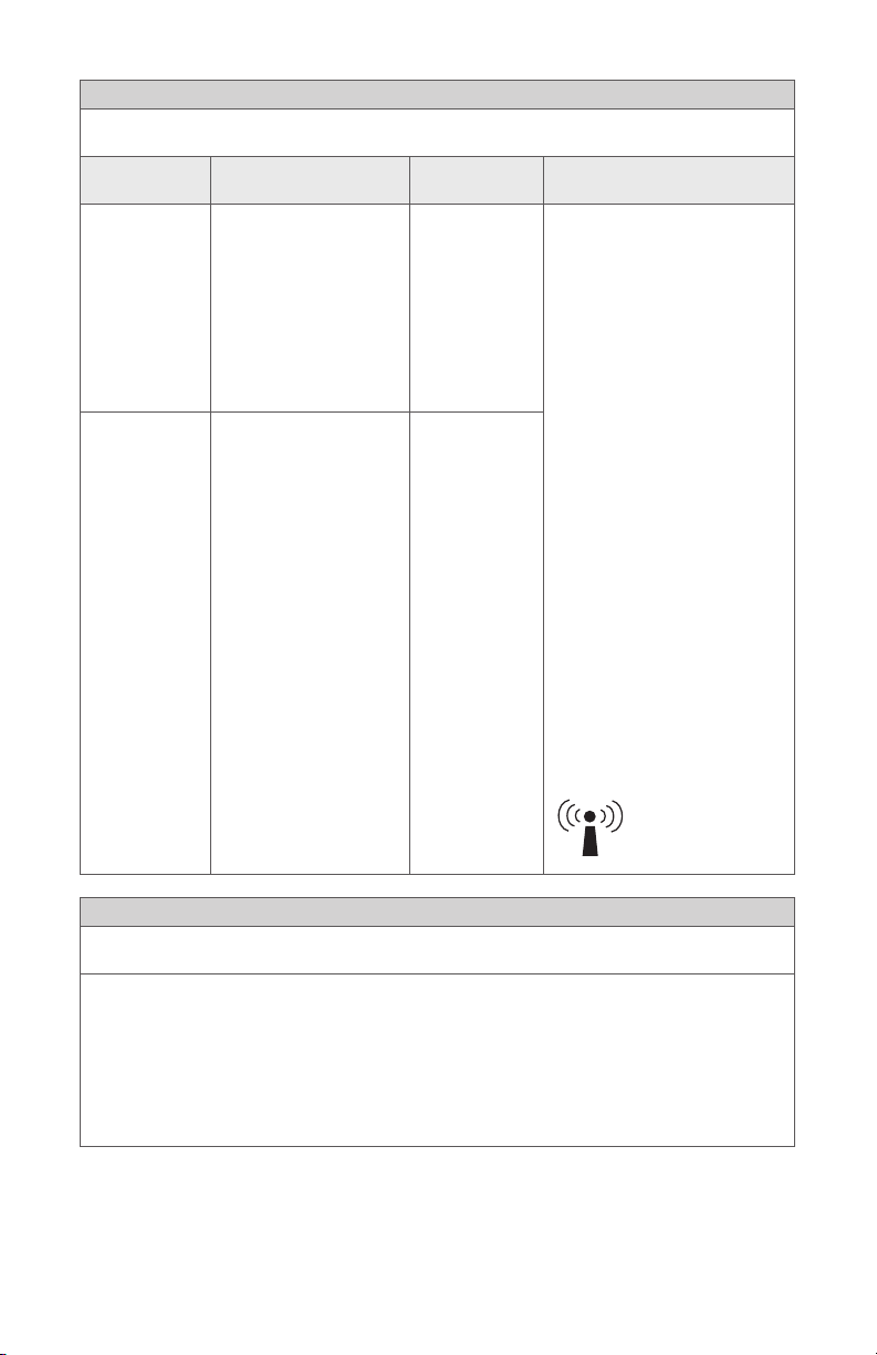
Guidance and Manufacturer’s Declaration: Electromagnetic Immunity
The device is intended for use in the electromagnetic environment specied below.
The customer or user of the device should ensure that it is used in such an environment.
Immunity Test IEC 60601 Test Level Compliance
Conducted RF
IEC 61000-4-6
Radiated RF
IEC 61000-4-3
6 Vrms
150 kHz to 80 MHz
3 V/m
80MHz to 2.7 GHz
Level
6 Vrms Portable and mobile RF
3 V/m
Electromagnetic Environment:
Guidance
communications equipment
should be used no closer to any
part of the device, including its
cables, than the recommended
separation distance calculated
from the equation applicable to
the frequency of the transmitter.
Recommended Separation
Distance
d = 2√P
80 MHz to 2.7 GHz
where P is the maximum output
power rating of the transmitter
in watts (W) according to the
transmitter manufacturer and d
is the recommended separation
distance in meters (m).
Field strengths from xed RF
transmitters, as determined
by an electromagnetic site
(a)
survey
the compliance level in each
frequency range
may occur in the vicinity of
equipment marked with the
following:
, should be less than
(b)
. Interference
Guidance and Manufacturer’s Declaration: Electromagnetic Immunity
The device is intended for use in the electromagnetic environment specied below. The customer or
user of the device should ensure that it is used in such an environment.
(a) Field strengths from xed transmitters, such as base stations for radio (cellular/cordless)
telephones and land mobile radios, amateur radio, AM and FM radio broadcast, and TV broadcast,
cannot be predicted theoretically with accuracy. To assess the electromagnetic environment due
to xed RF transmitters, an electromagnetic site survey should be considered. If the measured
eld strength in the location in which the device is used exceeds the applicable RF compliance
level above, the device should be observed to verify normal operation. If abnormal performance is
observed, additional measures may be necessary, such as reorienting or relocating the device.
(b) Over the frequency range 150 kHz to 80 MHz, eld strengths should be less than 3 V/m.
58
Page 63

Tested Specications for Immunity to RF Wireless Communications Equipment
Test
frequency
(MHz)
385
450
710
745
780
810
870
930
1720
1845
1970
2450
5240
5500
5785
Note: Portable RF communications equipment (including peripherals such as antenna cables and
external antennas) should be used no closer than 30 cm (12 inches) to any part of this device,
including cables specied by the manufacturer, otherwise the device performance could degrade.
Band
(MHz)
380–390
430–470
704–787
800–960
1700–1990
2400–2570
5100–5800
Service Modulation Maximum
TETRA 400 Pulse
GMRS 460,
FRS 460
LTE Band
13, 17
GSM
800/900,
TETRA 800,
iDEN 820,
CDMA 850,
LTE Band 5
GSM 1800;
CDMA 1900;
GSM 1900;
DECT; LTE
Band 1, 3, 4,
25; UMTS
Bluetooth,
WLAN,
802.11 b/g/n,
RFID 2450,
LTE Band 7
WLAN 802.11
a/n
modulation
18 Hz
FM
± 5 kHz
deviation
1 kHz sine
Pulse
modulation
217 Hz
Pulse
modulation
18 Hz
Pulse
modulation
217 Hz
Pulse
modulation
217 Hz
Pulse
modulation
217 Hz
Power
(W)
1.8 0.3 27
2.0 0.3 28
0.2 0.3 9
2.0 0.3 28
2.0 0.3 28
2.0 0.3 28
0.2 0.3 9
Distance
(m)
Immunity
Test Level
(V/m)
59
Page 64

Symbol Denitions
This device and its labeling contain symbols that provide important
information for the safe and proper use of the device. These symbols are
dened below.
Touchscreen Interface/Display Monitor
WB button (turn on White Balance test)
Camera button (capture photo)
Record button (start/stop video recording)
Home button (navigate to Home screen)
AIM button (navigate to SPY screen)
Settings button (navigate to Camera Settings screen)
Auto Light button (blue=feature is on; black=feature is o)
Flexi-Scope surgical specialty is selected
Overlay SPY mode is active (icon colors are red, green, and blue)
Contrast SPY mode is active (icon colors are all grey)
ENV SPY mode is active (icon colors are all green)
Device/Package Labeling
Consult instructions for use
Caution (consult instructions for use)
Consult instruction manual
60
Page 65
Federal law (USA) restricts this device to use by, or on order of, a
physician
Device is shipped non-sterile and must be sterilized before use
Date of manufacture
Legal manufacturer
Product catalog number
Product serial number
Quantity
Made in USA
The device meets European Union medical device requirements.
Stryker European representative
Denotes compliance to CAN/CSA C22.2 No60601-1 and
ANSI/AAMI 60601-1
Type BF applied part
1688 Camera Head connection
Power on/o (alternates when button is pushed)
Equipotentiality
Alternating current
Fuse rating
61
Page 66

User Manual
Device recycling code (applicable in China)
This product contains electrical waste or electronic equipment.
It must not be disposed of as unsorted municipal waste and
must be collected separately.
Radiation emitting
62
Page 67

Page 68

Stryker Endoscopy
5900 Optical Court
San Jose, CA 95138 USA
1-800-624-4422
U.S. Patents: www.stryker.com/patents
Stryker or its divisions or other corporate
aliated entities own, use or have applied
for the following trademarks or service
marks: SafeLight and the Stryker logo. All
other trademarks are trademarks of their
respective owners or holders.
P38139G
2020/02
WCR: NONE
 Loading...