

Stryker 1000, 1500 Maintenance Manual
IMPORTANT
File in your
maintenance
records
1000 Emergency Care Stretcher
1500 PACU Stretcher
MAINTENANCE MANUAL
For Parts or Technical Assistance
1–800–327–0770

Table of Contents
Introduction
Specifications 3. . . . . . . . . . . . . . . . . . . . . . . . . . . . . . . . . . . . . . . . . . . . . . . . . . . . . . . . . . . . . . . . . . . . . . . .
Warning / Caution / Note Definition 3. . . . . . . . . . . . . . . . . . . . . . . . . . . . . . . . . . . . . . . . . . . . . . . . . . . . . .
Preventative Maintenance
Cleaning 4. . . . . . . . . . . . . . . . . . . . . . . . . . . . . . . . . . . . . . . . . . . . . . . . . . . . . . . . . . . . . . . . . . . . . . . . . . . . .
Biannual Checklist 4. . . . . . . . . . . . . . . . . . . . . . . . . . . . . . . . . . . . . . . . . . . . . . . . . . . . . . . . . . . . . . . . . . . .
Service Information
Pneumatic Fowler Adjustment 5. . . . . . . . . . . . . . . . . . . . . . . . . . . . . . . . . . . . . . . . . . . . . . . . . . . . . . . . . .
Siderail Latch Adjustment 6. . . . . . . . . . . . . . . . . . . . . . . . . . . . . . . . . . . . . . . . . . . . . . . . . . . . . . . . . . . . . .
Pedal Linkage Adjustment – Dual Side Control Base 7. . . . . . . . . . . . . . . . . . . . . . . . . . . . . . . . . . . . . . .
Pedal Linkage Adjustment – Dual End Control Base 8. . . . . . . . . . . . . . . . . . . . . . . . . . . . . . . . . . . . . . .
Caster Assembly Replacement 9. . . . . . . . . . . . . . . . . . . . . . . . . . . . . . . . . . . . . . . . . . . . . . . . . . . . . . . . .
Caster Cover Installation And Removal 10. . . . . . . . . . . . . . . . . . . . . . . . . . . . . . . . . . . . . . . . . . . . . . . . . .
Hydraulic System Troubleshooting 11. . . . . . . . . . . . . . . . . . . . . . . . . . . . . . . . . . . . . . . . . . . . . . . . . . . . . .
Checking Hydraulic Fluid Level 12. . . . . . . . . . . . . . . . . . . . . . . . . . . . . . . . . . . . . . . . . . . . . . . . . . . . . . . . .
Removal Of Excess Air (Vacuum) From The Hydraulic System 12. . . . . . . . . . . . . . . . . . . . . . . . . . . . . .
Jack Descent Rate Adjustment 13. . . . . . . . . . . . . . . . . . . . . . . . . . . . . . . . . . . . . . . . . . . . . . . . . . . . . . . . .
Hydraulic Check Valve Replacement
Replacement Of Valve #1 14. . . . . . . . . . . . . . . . . . . . . . . . . . . . . . . . . . . . . . . . . . . . . . . . . . . . . . . . . .
Replacement Of Valve #2 15. . . . . . . . . . . . . . . . . . . . . . . . . . . . . . . . . . . . . . . . . . . . . . . . . . . . . . . . . .
Replacement Of Valve (Poppet) #3 15. . . . . . . . . . . . . . . . . . . . . . . . . . . . . . . . . . . . . . . . . . . . . . . . . .
Brake Adjustment 16. . . . . . . . . . . . . . . . . . . . . . . . . . . . . . . . . . . . . . . . . . . . . . . . . . . . . . . . . . . . . . . . . . . . .
Base Lubrication Points 16. . . . . . . . . . . . . . . . . . . . . . . . . . . . . . . . . . . . . . . . . . . . . . . . . . . . . . . . . . . . . . . .
Assembly Drawings and Parts Lists
Side Control Base Assembly (with Brakes) 18, 19. . . . . . . . . . . . . . . . . . . . . . . . . . . . . . . . . . . . . . . . . . . . . .
Brake Adjuster Assembly 20. . . . . . . . . . . . . . . . . . . . . . . . . . . . . . . . . . . . . . . . . . . . . . . . . . . . . . . . . . . . .
Brake Cam Assembly 21. . . . . . . . . . . . . . . . . . . . . . . . . . . . . . . . . . . . . . . . . . . . . . . . . . . . . . . . . . . . . . . .
Reduced Length Brake/Steer Base Option 23. . . . . . . . . . . . . . . . . . . . . . . . . . . . . . . . . . . . . . . . . . . . . .
End Control Base Assembly (with Brakes) 24, 25. . . . . . . . . . . . . . . . . . . . . . . . . . . . . . . . . . . . . . . . . . . . . .
End Control Brake Pedal Assembly, Foot 26. . . . . . . . . . . . . . . . . . . . . . . . . . . . . . . . . . . . . . . . . . . . . . .
End Control Brake Pedal Assembly, Head 26. . . . . . . . . . . . . . . . . . . . . . . . . . . . . . . . . . . . . . . . . . . . . .
Caster Assembly with Steerlock 27. . . . . . . . . . . . . . . . . . . . . . . . . . . . . . . . . . . . . . . . . . . . . . . . . . . . . . .
Caster and Caster Cover Replacement Kits 28. . . . . . . . . . . . . . . . . . . . . . . . . . . . . . . . . . . . . . . . . . . . .
Fifth Wheel Assembly 29. . . . . . . . . . . . . . . . . . . . . . . . . . . . . . . . . . . . . . . . . . . . . . . . . . . . . . . . . . . . . . . .
Side Control Base Assembly (with Jacks) 30, 31. . . . . . . . . . . . . . . . . . . . . . . . . . . . . . . . . . . . . . . . . . . . . . .
Pedal Base Assembly, Pump 32. . . . . . . . . . . . . . . . . . . . . . . . . . . . . . . . . . . . . . . . . . . . . . . . . . . . . . . . .
Pedal Base Assembly, Head End, Left 33. . . . . . . . . . . . . . . . . . . . . . . . . . . . . . . . . . . . . . . . . . . . . . . . .
Pedal Base Assembly, Head End, Right 34. . . . . . . . . . . . . . . . . . . . . . . . . . . . . . . . . . . . . . . . . . . . . . . .
End Control Base Assembly (with Jacks) 36, 37. . . . . . . . . . . . . . . . . . . . . . . . . . . . . . . . . . . . . . . . . . . . . . .
Pump Pedal Assembly, Head 38. . . . . . . . . . . . . . . . . . . . . . . . . . . . . . . . . . . . . . . . . . . . . . . . . . . . . . . . .
Pump Pedal Assembly, Foot 38. . . . . . . . . . . . . . . . . . . . . . . . . . . . . . . . . . . . . . . . . . . . . . . . . . . . . . . . . .

Table of Contents
Assembly Drawings and Parts Lists (Continued)
Jack Assembly 40. . . . . . . . . . . . . . . . . . . . . . . . . . . . . . . . . . . . . . . . . . . . . . . . . . . . . . . . . . . . . . . . . . . . . .
Jack Base Assembly 41. . . . . . . . . . . . . . . . . . . . . . . . . . . . . . . . . . . . . . . . . . . . . . . . . . . . . . . . . . . . . . . . .
End Control Base Labeling Assembly 42. . . . . . . . . . . . . . . . . . . . . . . . . . . . . . . . . . . . . . . . . . . . . . . . . .
End Control Stretcher Graphics 42.1. . . . . . . . . . . . . . . . . . . . . . . . . . . . . . . . . . . . . . . . . . . . . . . . . . . . . . .
Side Control Stretcher Graphics 42.2. . . . . . . . . . . . . . . . . . . . . . . . . . . . . . . . . . . . . . . . . . . . . . . . . . . . . . .
Side Control Base Labeling Assembly 43. . . . . . . . . . . . . . . . . . . . . . . . . . . . . . . . . . . . . . . . . . . . . . . . . .
24” Litter Carrier Assembly 44. . . . . . . . . . . . . . . . . . . . . . . . . . . . . . . . . . . . . . . . . . . . . . . . . . . . . . . . . . .
24” Litter Carrier Assembly, with Push Bar 45. . . . . . . . . . . . . . . . . . . . . . . . . . . . . . . . . . . . . . . . . . . . . .
24” Push Bar Assembly 46. . . . . . . . . . . . . . . . . . . . . . . . . . . . . . . . . . . . . . . . . . . . . . . . . . . . . . . . . . . . . .
24” Litter Carrier Assembly – Knee Gatch Litter 48. . . . . . . . . . . . . . . . . . . . . . . . . . . . . . . . . . . . . . . . . .
24” Litter Carrier Assembly, Pneumatic Fowler/Crank Gatch, with Push Bar 49. . . . . . . . . . . . . . . . .
24” Fiberresin Manual Fowler/Stationary Foot End Litter Assembly 51. . . . . . . . . . . . . . . . . . . . . . . . .
24” Fiberresin Pneumatic Fowler/Stationary Foot Litter Assembly 52. . . . . . . . . . . . . . . . . . . . . . . . . .
24” Aluminum Pneumatic Fowler/Stationary Foot Litter Assembly 53. . . . . . . . . . . . . . . . . . . . . . . . . .
Yoke Housing Assembly 54. . . . . . . . . . . . . . . . . . . . . . . . . . . . . . . . . . . . . . . . . . . . . . . . . . . . . . . . . . . . . .
24” Aluminum Manual Fowler/Stationary Foot End Litter Assembly 55. . . . . . . . . . . . . . . . . . . . . . . . .
24” Aluminum Pneumatic Fowler/Crank Gatch Litter Assembly 56, 57. . . . . . . . . . . . . . . . . . . . . . . . . . . .
29” Litter Carrier Assembly 58. . . . . . . . . . . . . . . . . . . . . . . . . . . . . . . . . . . . . . . . . . . . . . . . . . . . . . . . . . .
29” Litter Carrier Assembly with Pushbar 59. . . . . . . . . . . . . . . . . . . . . . . . . . . . . . . . . . . . . . . . . . . . . . .
29” Pushbar Assembly – Pneumatic Fowler Litter 60. . . . . . . . . . . . . . . . . . . . . . . . . . . . . . . . . . . . . . . .
29” Pushbar Assembly – Crank Fowler Litter 61. . . . . . . . . . . . . . . . . . . . . . . . . . . . . . . . . . . . . . . . . . . .
29” Pneumatic Fowler/Stationary Foot End Litter Assembly 63. . . . . . . . . . . . . . . . . . . . . . . . . . . . . . .
29” Pneumatic Fowler/Crank Gatch Litter Assembly 64. . . . . . . . . . . . . . . . . . . . . . . . . . . . . . . . . . . . . .
29” Crank Fowler/Crank Gatch Litter Assembly 66. . . . . . . . . . . . . . . . . . . . . . . . . . . . . . . . . . . . . . . . . .
29” Crk. Fowler (Head End Crank)/Stationary Foot Litter 68. . . . . . . . . . . . . . . . . . . . . . . . . . . . . . . . . .
29” Crk. Fowler (Foot End Crk.)/Stationary Foot Litter 69. . . . . . . . . . . . . . . . . . . . . . . . . . . . . . . . . . . .
29” Manual Fowler/Stationary Foot End Litter Assembly 70. . . . . . . . . . . . . . . . . . . . . . . . . . . . . . . . . .
Siderail Assembly, Left & Right 71. . . . . . . . . . . . . . . . . . . . . . . . . . . . . . . . . . . . . . . . . . . . . . . . . . . . . . . .
Foot Board/Chartholder 72. . . . . . . . . . . . . . . . . . . . . . . . . . . . . . . . . . . . . . . . . . . . . . . . . . . . . . . . . . . . . .
Upright Oxygen Bottle Holder 72. . . . . . . . . . . . . . . . . . . . . . . . . . . . . . . . . . . . . . . . . . . . . . . . . . . . . . . . .
X–Ray Cassette Assembly 74. . . . . . . . . . . . . . . . . . . . . . . . . . . . . . . . . . . . . . . . . . . . . . . . . . . . . . . . . . .
X–Ray Cassette Assembly 75. . . . . . . . . . . . . . . . . . . . . . . . . . . . . . . . . . . . . . . . . . . . . . . . . . . . . . . . . . .
Padded Foot Extension Assembly 76. . . . . . . . . . . . . . . . . . . . . . . . . . . . . . . . . . . . . . . . . . . . . . . . . . . . .
Warranty
Obtaining Parts and Service 77. . . . . . . . . . . . . . . . . . . . . . . . . . . . . . . . . . . . . . . . . . . . . . . . . . . . . . . . . . . .
Supplemental Warranty Coverage 77. . . . . . . . . . . . . . . . . . . . . . . . . . . . . . . . . . . . . . . . . . . . . . . . . . . . . . .
Return Authorization 78. . . . . . . . . . . . . . . . . . . . . . . . . . . . . . . . . . . . . . . . . . . . . . . . . . . . . . . . . . . . . . . . . .
Freight Damage Claims 78. . . . . . . . . . . . . . . . . . . . . . . . . . . . . . . . . . . . . . . . . . . . . . . . . . . . . . . . . . . . . . . .

Introduction
INTRODUCTION
This manual is designed to assist you with the operation and maintenance of the 1000 Emergengy Care
Stretcher and the 1500 PACU Bed. Read it thoroughly before using the equipment or beginning any maintenance on it.
SPECIFICATIONS
1000 1500
Maximum Weight Capacity 500 pounds 500 pounds
Overall Bed Length \ Width 78” \ 28” 78” \ 33”
Minimum \ Maximum Bed Height 22” \ 35” 22” \ 35”
Fowler Angle 0 to 90 degrees 0 to 90 degrees
Knee Gatch Angle 0 to 35 degrees 0 to 35 degrees
Trendelenberg \ Reverse Trendelenberg +12 to –18 degrees +12 to –18 degrees
WARNING / CAUTION / NOTE DEFINITION
The words WARNING, CAUTION and NOTE carry special meanings and should be carefully reviewed.
WARNING
The personal safety of the patient or user may be involved. Disregarding this information could result in injury
to the patient or user.
CAUTION
These instructions point out special procedures or precautions that must be followed to avoid damaging the
equipment.
NOTE
This provides special information to make maintenance easier or important instructions clearer.
3

Preventative Maintenance
CLEANING
1. Hand wash all surfaces of the bed with warm water and mild detergent. Dry thoroughly.
2. Clean Velcro AFTER EACH USE. Saturate Velcro with disinfectant and allow disinfectant to evaporate.
(Appropriate disinfectant for nylon Velcro should be determined by the hospital.)
NOTE
Quaternary Germicidal Disinfectants, used as directed, and/or Chlorine Bleach products, typically 5.25% So dium Hypochlorite in dilutions ranging between 1 part bleach to 100 parts water, and 2 parts bleach to 100
parts water are not considered mild detergents. These products are corrosive in nature and may cause damage to your stretcher if used improperly . If these types of products are used to clean Stryker patient handling
equipment, measures must be taken to insure the stretchers are rinsed with clean water and thoroughly dried
following cleaning. Failure to properly rinse and dry the stretchers will leave a corrosive residue on the surface
of the stretcher, possibly causing premature corrosion of critical components. Failure to follow the above
directions when using these types of cleaners may void this product’s warranty.
BIANNUAL CHECKLIST
All fasteners secure (reference all assembly prints)
Siderails move and latch properly (page 6)
All casters lock with brake pedal engaged
Steer function working properly
All casters secure and swivel properly (page 9)
Body restraints working properly
I.V. pole intact and operating properly (page 73)
Oxygen bottle holder intact and operating properly
Knee Gatch and Fowler operate and latch properly (refer to operations manual)
Trendelenberg/Reverse Trendelenberg operating properly
No rips or cracks in mattress cover
Ground chain intact
No leaks at hydraulic connections
Hydraulic jacks holding properly (page 11)
Hydraulic drop rate set properly (page 13)
Hydraulic oil level sufficient (page 12)
Lubricate where required, including the brake adjuster assembly and brake cam
Serial No.______________
______________
______________
______________
______________
Completed By:_________________________________ Date:_____________
4

Service Information
PNEUMATIC FOWLER ADJUSTMENT
Required Tools:
1/8” Hex Allen Wrench 1/2” Socket w/Ratchet
3/32” Hex Allen Wrench Channel Lock Pliers
5/32” Hex Allen Wrench Towel or Cloth
7/16” Open End Wrench Thread ”Locktite”
Adjustment Procedure:
1. Refer to drawing 1000–144 (Pneumatic Fowler Assembly, page 56).
2. For easier access, move Fowler to 75 degrees or higher.
3. Using a 3/32” hex Allen wrench, remove set screws (AH), located in center of yokes (AC).
4. Wrap a towel or cloth around the gas cylinder actuator shaft(s) so as not to mark the shaft. Using channel
lock pliers, turn actuator shaft(s) into yoke(s) (AC) until tight.
5. Using thread locktite, reinstall set screws (AH).
6. While holding the jam nuts (AF) with a 1/2” socket, turn the adjustment screws (CA) using a 5/32” hex Allen
wrench until they JUST touch the cylinder pins.
7. Verify that the distance between the handle (AR) and the end of the Fowler tube (F) is 1 1/4”. If it is not,
while holding jam nut (BR) with a 7/16” open end wrench turn adjustment screw (AD) with a 1/8” hex Allen
wrench until the 1 1/4” measurement is achieved. Retighten jam nut (BR).
8. Be sure the Fowler will travel from flat to at least 90 degrees. If it doesn’t, turn each adjustment screw (CA)
clockwise 1/2 turn. Repeat until at least 90 degrees of travel is achieved.
9. Lower the Fowler to a 5–10 degree angle and release the handle. Apply approximately 50 pounds downward to the end of the Fowler. If either side drifts down, turn the adjustment screw (CA) on that side 1/4
turn counterclockwise. Repeat until the Fowler is firm with 50 pounds applied.
10. While holding the adjustment screws (CA), tighten the jam nut spacers (AF).
5

Service Information
SIDERAIL LATCH ADJUSTMENT
Required Tools:
1/8 Hex Allen Wrench
WARNING
The siderail latch adjustment is pre–set at the factory, and there should not normally be a need for readjustment. If adjustment must be done it is important to follow the procedure below. If it is no t don e pro per ly, injury
to the patient or user could occur.
Adjustment Procedure:
1. Using a 1/8 hex Allen wrench, adjust the hex Allen screw located on the latch assembly opposite the latch.
Turning the Allen screw clockwise will DECREASE the amount of ”play” in the latching mechanism. Turn-
ing counterclockwise will INCREASE the amount.
NOTE
The amount of ”play” in the siderail, when in full up engaged position, should be approximately 1/8 to 3/16
inches.
CAUTION
Too much ”play” when the siderail is in the full up engaged position will give the siderail the appearance of
being unstable and could also cause premature wearing of the latch system.
Too little ”play” will obstruct the latch and keep it from engaging completely in the full up position, which may
cause damage to the latch and/or injury to the patient or user.
6
Service Information
PEDAL LINKAGE ADJUSTMENT – DUAL SIDE CONTROL BASE
Required Tools:
3/32 Hex Allen Wrench
7/16 Open End Wrench
1/2 Open End Wrench
(2) Wooden blocks (10 – 12 inches in length)
Adjustment Procedure:
1. Pump the litter up to full height.
2. Lift the base hood, separating the hood from the base frame. Using the wooden blocks, support the base
hood.
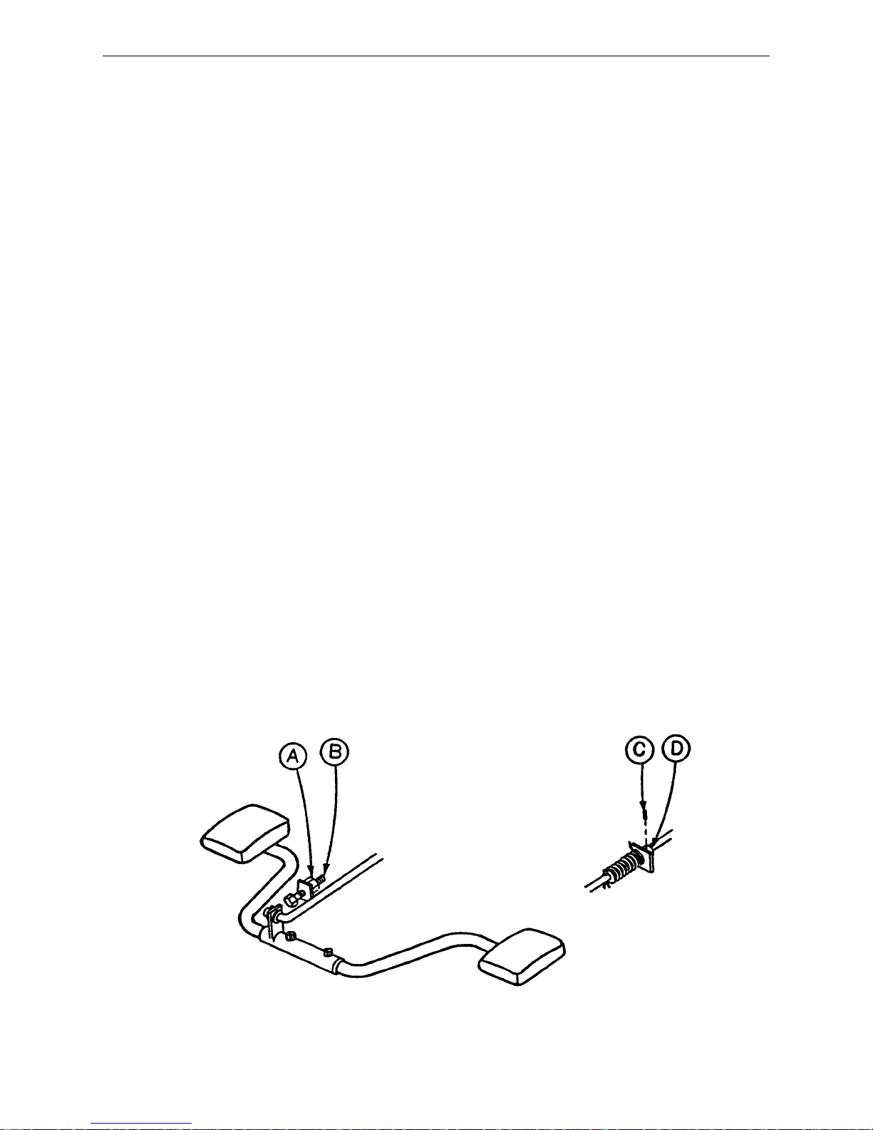
3. To adjust the foot end descent pedal, use a 5/32 hex Allen wrench to loosen the set screw (C) in the stop
collar (D) on the release rod. Hold the pedal parallel to the floor and slide the collar up to the bracket on
the release rod. Tighten the set screw on the stop collar. Be sure the head end and foot end descent
pedals are level with each other. Repeat for the head end pedal, if necessary.
4. Once the pedals are level, be sure the paddle on the end of the release rod for the foot end jack is slightly
touching the actuating stem on the jack base. If it is not, use a 3/32 hex Allen wrench to loosen the set
screw on the paddle hub. Adjust the paddle to JUST touch the stem of the jack. Tighten the set screw
in the paddle hub. Repeat for the head end jack, if necessary.
5. Depress the pedal for the foot end jack. The jack should start to descend about the same time the paddle
on the end of the rod contacts the sleeve on the jack actuating stem. The bracket on the foot pedal body
should hit the stop screw (B). Any further movement could cause damage to the stem components inside
the jack housing. To adjust the stop screw, use a 1/2 open end wrench to loosen the hex jam nut (A).
Turn the screw and re–tighten the hex jam nut. Repeat for the head end jack.
6. Pump the litter up to full height.
7. Step on both descent pedals at the same time. Both ends of the litter should lower with the foot end lowering slightly faster than the head end. If it does not, refer to the procedure for adjusting the jack descent
rate.
8. Remove the wooden blocks supporting the base hood. Use the pedal cut–outs on the side of the hood
as a guide for proper re–positioning.
7
Service Information
PEDAL LINKAGE ADJUSTMENT – DUAL END CONTROL BASE
Required Tools:
7/16 Open End Wrench
1/2 Open End Wrench
(2) Wooden Blocks (10 – 12 inches in length)
Adjustment Procedure:
1. Pump the litter up to full height.
2. Lift the base hood, separating the hood from the base frame. Using the wooden blocks, support the base
hood.
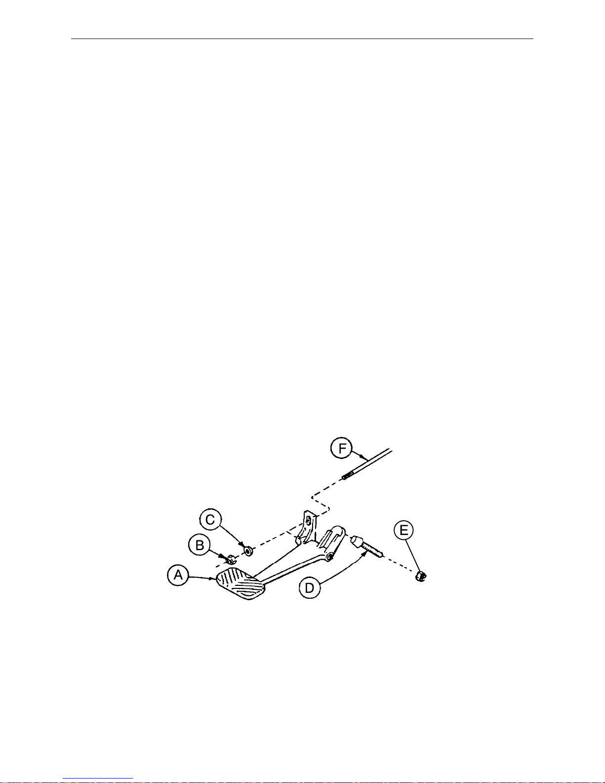
3. The descent pedals should be level with each other and there should be approximately 4 inches between
the floor and the bottom of the pedal. To raise the pedal height, use a 1/2 open end wrench to loosen the
hex jam nut (E). Using your hand, turn the screw (D) into the bracket. To lower the pedal height, loosen
the screw. Tighten the hex jam nut (E) after the correct height is achieved.
4. Once the pedals are level, the release rod can be adjusted. Using a 7/16 wrench, turn nut (B) clockwise
to shorten the release length and counterclockwise to increase the length.
5. Depress the pedal and be sure the jack descent is triggered when the pedal is approximately one inch from
the floor. The descent should stop when the pedal is released and the jack height should hold. Repeat
the above procedures for the descent pedal at the other end of the bed.
6. After adjusting each descent pedal individually, depress both pedals at the same time. Both jacks should
start descending when the pedals are approximately one inch from the floor. The foot end should lower
slightly faster than the head end. If it does not, see procedure for adjusting the jack descent rate.
7. Remove the wooden blocks supporting the base hood and secure the hood to the base frame.
8
Service Information
CASTER ASSEMBLY REPLACEMENT*
Required Tools:
1/8 Roll Pin Punch Drill with 1/8 inch Drill Bit
Flat Punch (any size larger than 1/8) Hammer
Needle Nose Pliers Floor Jack
3/4 Inch Wrench (2) Wooden Blocks (10 – 12 inches in length)
1 Inch Wrench Torque Wrench (w/ Ft. Lbs. Adjust.)
Replacement Procedure:
1. Pump the litter up to full height.
2. Lift the base hood, separating the hood from the base frame. Using the wooden blocks, support the base
hood,
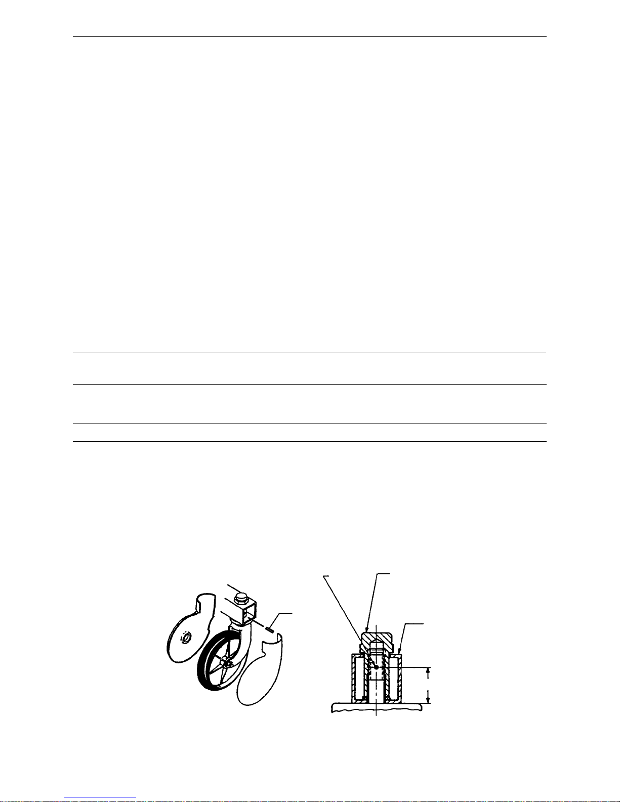
3. Using a 1/8 roll pin punch and hammer, remove roll pin located in center of lug nut holding wheel assembly
to base frame.
4. Carefully remove plastic wheel covers.
5. Using a floor jack, lift base frame approximately 4 inches off the ground.
6. While holding cap screw with a 3/4 inch wrench, turn lug nut with a 1 inch wrench to loosen wheel assembly
from base frame. Remove wheel.
7. Install the new wheel assembly with new lug nut and tighten down to 60 – 65 foot–pounds torque.
WARNING
Never reuse the old lug nut, cap screw or roll pin once removed from base frame.
8. Lower the floor jack and set aside to be used, if needed, with another wheel.
9. Drill a 1/8 hole in center of lug nut, going completely through the lug nut.
CAUTION
Be careful not to ”oblong” the hole in the lug nut when drilling.
10. Using needle nose pliers, hold on to roll pin and tap into place. Finish driving roll pin with a flat head punch
and a hammer until flush with the lug nut.
11. Install plastic wheel covers onto wheel.
12. Remove the wooden blocks supporting the base hood and secure the hood to the base frame.
*See page 28 for replacement part numbers
1/8 Inch
Dia.
Through
Roll Pin
Lug Nut
(60–65 Ft.–Lb.)
Support Tube
1 Inch
9
Service Information
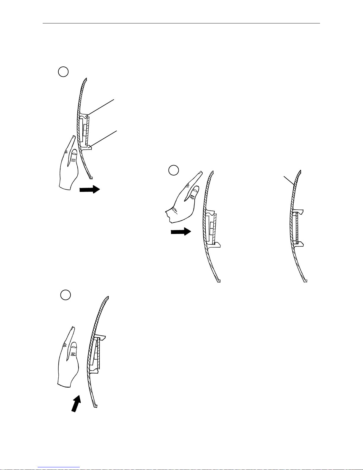
CASTER COVER INSTALLATION AND REMOVAL
1.
Looking through the larger of the two side cut–outs,
Double Prongs
Single Prong
align cover with axle nut or bolt head, as shown.
Push down on the opposite side of the cover until
single prong engages with caster horn.
Top View (Cut–Away)
Push with palm on cover until
double prongs engage.
3.
2.
Properly Attached
Cover
Top View (Cut–Away)
To remove wheel cover, insert large screwdriver into cut–out in
side of wheel cover and into the space between the double prongs.
Pry up cover to disengage double prongs and push sharply upward
to disengage single prong.
Top View (Cut–Away)
10

Service Information
HYDRAULIC SYSTEM TROUBLESHOOTING
NOTE
Be sure the pedal linkage has been adjusted properly before beginning service on the jacks (see page 7
or page 8).
PROBLEM/SYMPTOM SOLUTION
Jack will not raise to full height. Add hydraulic fluid (see p.12). Check for leaks.
Jack will not hold in raised position. Close the needle valve completely. If the jack
holds, replace valve #1 (see p. 14). If the jack
does not hold, replace valve #2 (see p. 15).
Jack will not pump up and the jack actuator rod
does not move.
Jack will not pump up but the jack actuator rod
does move when the pump pedal is activated.
Jack will not pump up and the jack actuator rod
may or may not move.
Close the needle valve. If the jack will now pump
up, replace valve #1. If the jack still will not pump
up after closing the needle valve, replace valve #3
(see p. 15).
Replace valve #2 (see p. 15).
Remove excess air (vacuum) in system (see p.
12).
Contact Stryker technical service at 1–800–327–0770 for further assistance.
11

Service Information
CHECKING HYDRAULIC FLUID LEVEL
Required Tools:
3/8 Open End Wrench
3/4 Open End Wrench
Procedure:
WARNING
To avoid personal injury or damage to the stretcher, remove the litter and the base hood before beginning
service on the jacks.
1. Using a 3/8 open end wrench, remove square head set screws from both head and foot end jack support
tubes. Remove litter top and set aside.
2. Lift base hood off base frame and set aside.
3. Be sure there are no hydraulic leaks. If there are, jack replacement will be necessary.
4. Lower the jack to the full down position.
5. Using a 3/4 open end wrench, slowly turn the fill plug located on the side of the reservoir counterclockwise
to allow excess system pressure to vent. Remove the fill plug.
6. The hydraulic fluid should be visible at the bottom of the fill hole. If it is not, add Mobil Aero HFA hydraulic
fluid (Stryker part number 2020–70–475) until the fluid is visible at the bottom of the fill hole. Replace the
fill plug.
CAUTION
Use of other types of oil may damage hydraulic units.
7. Replace the hood and the litter.
REMOVAL OF EXCESS AIR (VACUUM) FROM THE HYDRAULIC SYSTEM
Procedure:
1. Verify all hydraulic linkages are secure and operating properly (see pedal linkage adjustment procedure
page 7 or 8).
2. Using pump pedal, actuate system several times. This will force the air through the system and the jack
should now pump up.
12

Service Information
JACK DESCENT RATE ADJUSTMENT
Required Tools:
Screwdriver
(2) Wooden Blocks (10 – 12 inches in length)
Adjustment Procedure:
1. Pump the litter up to full height.
2. Lift the base hood, separating the hood from the base frame. Using the wooden blocks, support the base
hood.
3. The descent rate needle valve is located on the base of the jack. Turning the needle valve clockwise, with
a screwdriver, will decrease the rate of descent. Turning it counterclockwise will increase the rate of descent.
4. Adjust the needle valve so that the foot end of the stretcher descends slightly faster than the head end.
NOTE
The larger percentage of a patient’s weight is located in the torso area. Adjust descent rate accordingly.
5. Remove the wooden blocks supporting the base hood and secure the hood to the base frame.
NOTE
The jack descent rate was preset at the factory to drop the foot end faster than the head. It is recommended
that the foot drop faster to avoid patient disorientation.
13
Service Information
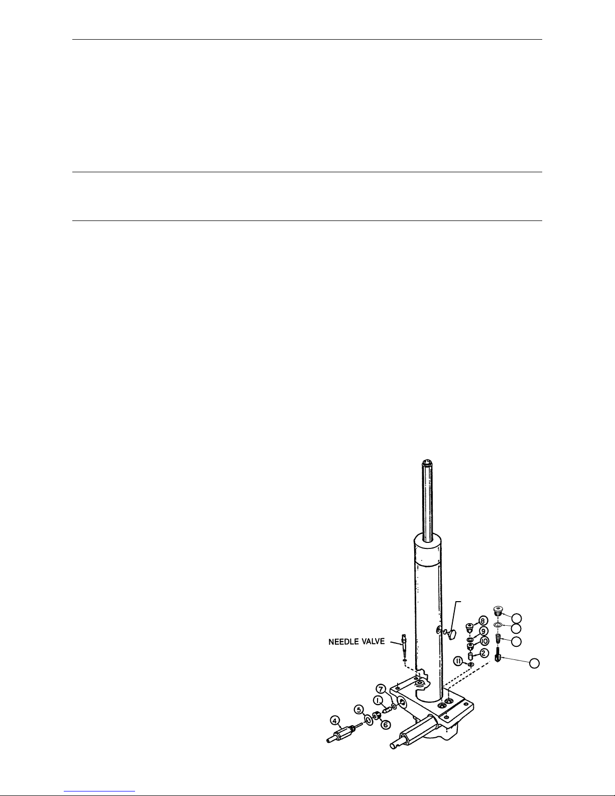
HYDRAULIC CHECK VALVE REPLACEMENT
Required Tools:
3/8 Open End Wrench Stiff Wire (with bent, pointed end) Small Needle Nose Pliers
3/4 Open End Wrench Torque Wrench (with Ft. Lbs. adjust.)
7/32 Hex Allen Wrench 1/2 Inch Diameter Rod
Replacement of Valve #1
WARNING
To avoid personal injury or damage to the stretcher, remove the litter and the base hood before beginning
service on the stretcher.
1. Using a 3/8 open end wrench, remove square head set screws from both head and foot end jack support
tubes. Remove litter top and set aside.
2. Lift base hood off base frame and set aside.
3. Lower the jack to full down position. The actuator must be manually lowered while depressing the appropriate release pedal.
4. Remove the pin body assembly (4) with a 3/4 open end wrench and discard the housing gasket (5).
NOTE
Although the hydraulic fluid is not under pressure, some fluid loss will occur . The fluid loss should be minimal
but covering the floor is advisable.
5. Using a 7/32 hex Allen wrench, remove the valve plug (6).
6. Using a stiff wire with a bent, pointed end, remove and discard the valve (1) and the seal (7).
7. Install the new seal (7) flat to the bottom of its hole with a 1/2 inch diameter rod and install the new valve
(1) with the beveled end out (as shown in the illustration).
8. Install the valve plug (6) with the countersunk end first and the beveled end out. Tighten to 10 foot pounds
torque.
9. Install the pin body assembly (4) with the new housing gasket (5) and tighten to 10 foot pounds torque.
10. Pump up the jack to the maximum height. Apply weight to be sure the jack holds its position and there
are no hydraulic leaks before replacing the base hood and the litter.
ITEM PART NO. PART NAME
1 926–20–153 Check Valve
2 926–20–153 Check Valve
3 715–1–341 Poppet
4 715–100–312 Pin Housing Assembly
715–270–100 Valve Assembly**
5 715–1–330 Housing Gasket
6 715–1–309 Valve Plug
7 926–20–154 Seal
8 715–1–101 Base Plug
9 926–20–156 Seal
10 715–1–309 Valve Plug
11 926–20–154 Seal
12 715–1–301 Base Plug
13 926–20–156 Seal
14 390–2–134 Conical Comp. Spring
* Used on jack part number 715–100–310.
**Used on jack part number 715–270–10.
(see label on side of jack reservoir for jack part number)
*
FILLER PLUG
12
13
14
3
14

Service Information
HYDRAULIC CHECK VALVE REPLACEMENT (CONT’D)
Replacement of Valve #2
WARNING
To avoid personal injury or damage to the stretcher, remove the litter and the base hood before beginning
service on the jacks. Lower the jack rod completely to relieve the pressure on the pump piston side of the
jack. This will prevent large hydraulic fluid loss and possible damage when the base plugs are removed.
1. Remove the base plug (8) and discard the seal (9).
2. Remove the valve plug (10).
3. Using a stiff wire with a bent, pointed end, remove the valve (2) and the seal (11) and discard the seal.
4. Install the new seal (11) flat to the bottom of its hole with a 1/2” diameter rod.
5. Install the new valve (2) with the beveled end out (as shown in the illustration).
6. Install the valve plug (10) and tighten to 10 foot–pounds torque.
7. Install the new seal (9) with the base plug (8) and tighten to 10 foot–pounds torque.
8. Pump up the jack to the maximum height.
9. Be sure there are no hydraulic leaks before replacing the base hood and the litter.
Replacement of Valve (Poppet) #3
WARNING
To avoid personal injury or damage to the stretcher, remove the litter and the base hood before beginning
service on the jacks. Lower the jack rod completely to relieve the pressure on the pump piston side of the
jack. This will prevent large hydraulic fluid loss and possible damage when the base plugs are removed.
1. Remove the base plug (12) and discard the seal (13).
2. Remove the compression spring (14).
3. Using a small needle nose pliers, remove the poppet (3).
4. Install the new poppet (3).
5. Install the compression spring (14).
6. Install the new seal (13) and the base plug (12) and tighten to 10 foot–pounds torque.
7. Pump up the jack to the maximum height to check its operation.
8. Check for hydraulic leaks before replacing the base hood and the litter.
15
Required Tools:
3/32” Hex Allen Wrench
Pry Bar
Thread ”Locktite”
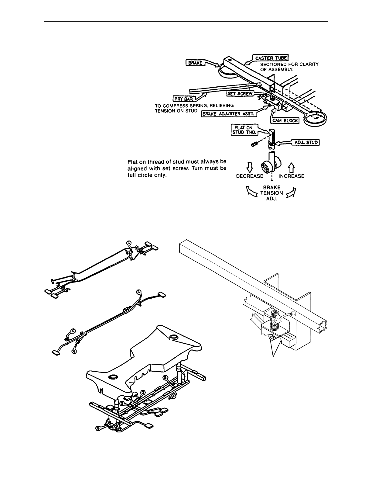
Service Information
BRAKE ADJUSTMENT
BASE LUBRICATION POINTS
1. Lubricate brake adjuster rod
around area shown with MPG–2
grease or equivalent.
Do not grease area shown.
16

Notes
17
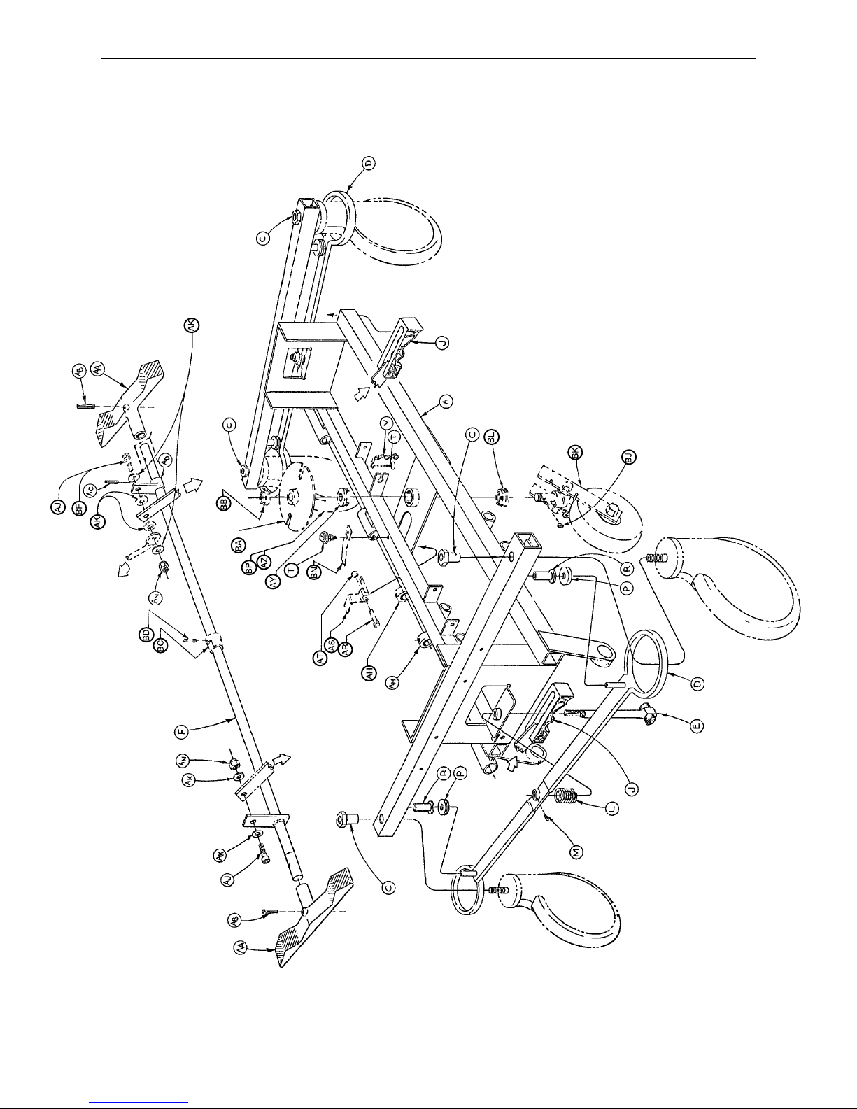
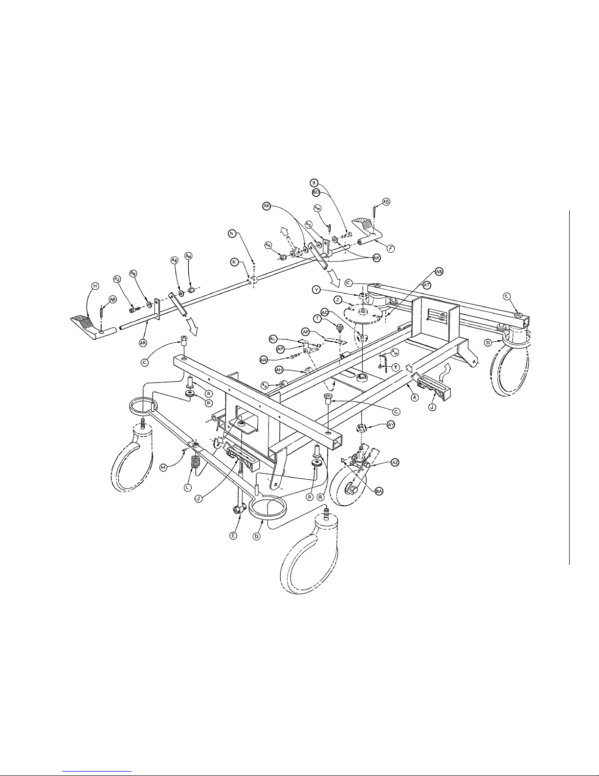
715–1–250 Side Control Base Assembly (with Brakes)
18
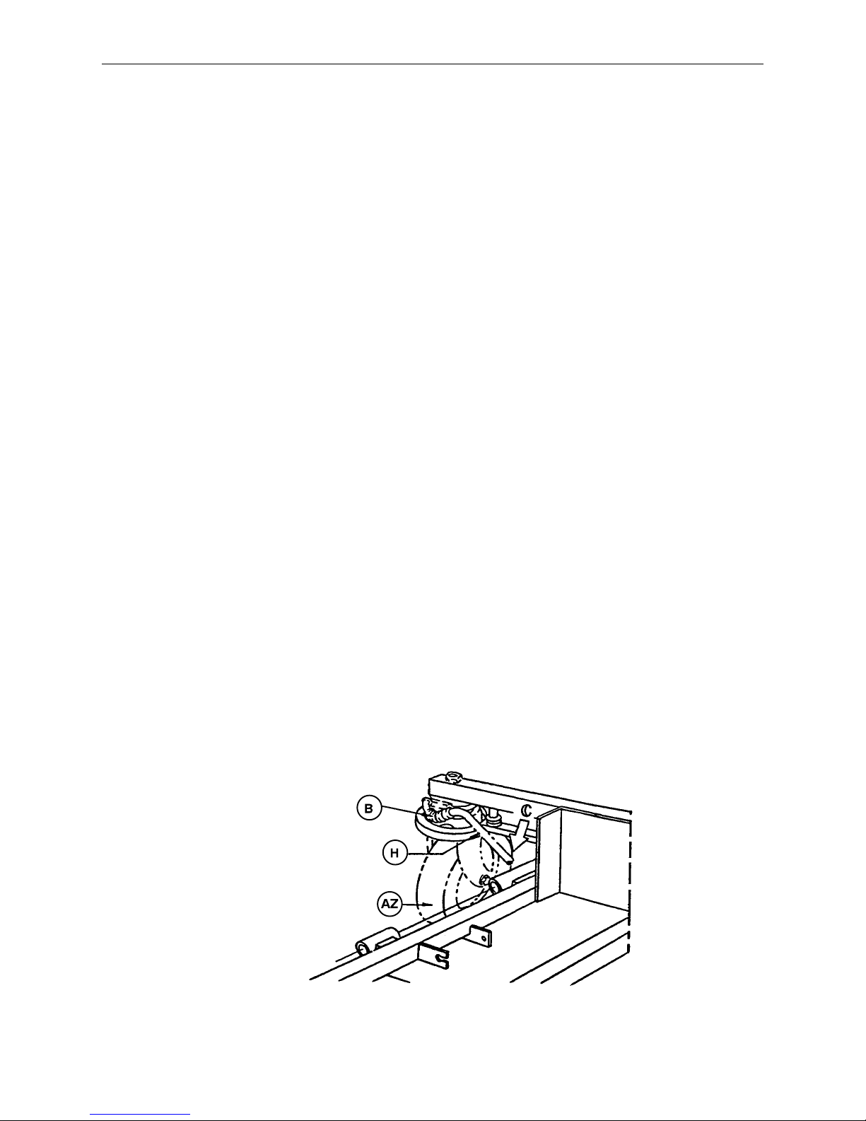
715–1–250 Side Control Base Assembly (with Brakes)
Item Part No. Part Name Qty.
A 715–1–245 Base Weldment Assembly 1
B38–211 Spring 1
C 715–1–158 Caster Nut 4
D 715–1–61 Caster Brake Assembly 2
E (Page 20) Brake Adjuster Assembly 2
F 715–1–231 Brake/Steering Rod Assembly 1
H 1000–10–62 Steering Lock Linkage Bar 1
J (Page 21) Brake Cam Assembly 2
L 715–1–94 Compression Spring 2
M21–50 Set Screw 2
P 715–1–11 Brake Cushion 4
R 946–1–116 Brake Bar Bushing 4
T23–25 Self–Tapping Screw 2
V 715–1–156 Grounding Chain 1
AA 715–201–201 Brake/Steer Pedal 2
AB 26–261 Groove Pin 2
AC 26–13 Roll Pin 1
AD 715–1–165 Actuator Plate Assembly 1
AH 42–20 Collar w/ Set Screw 2
AJ 8–17 Soc. Hd. Cap Screw 2*
AK 14–2 Nylon Washer 4
AN 16–2 Fiberlock Nut 2
AR 3–20 Hex Hd. Cap Screw 1
AS 715–1–217 Fifth Wheel Latch 1
AT 16–16 Nylock Nut 1
AY 715–1–157 Fifth Wheel Bearing 1
AZ (Page 27) Steering Caster Assembly 1**
BA 715–1–337 Fifth Wheel Plate Assembly 1
BB 16–49 Flexlock Nut 1
BC 715–1–161 Fifth Wheel Cam 1
BD 26–8 Roll Pin 1
BF 8–21 Soc. Hd. Cap Screw 1**
BJ 715–1–149 Woodruff Key 1
BK (Page 29) Fifth Wheel Assembly 1
BL 81–219 Bearing 1
BN 715–1–136 Fifth Wheel Spring 1
BP (Page 28) Caster Wheel Assembly 3 ***
*Item AJ to be used only when fifth wheel is ordered.
**Items AZ and BF to be used only when steerlock caster is ordered.
***Item BP quantity of four when fifth wheel is ordered.
STEERLOCK
ASSEMBLY
DETAIL
19
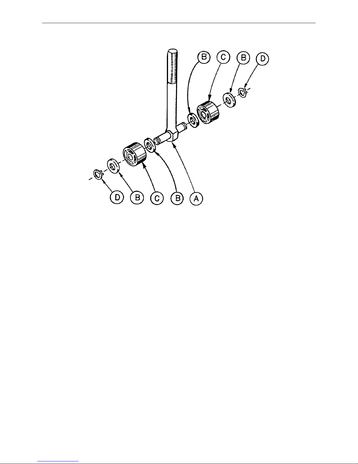
715–1–150 Brake Adjuster Assembly
Item Part No. Part Name Qty.
A 715–1–62 Threaded Stud Assembly 1
B14–4 Nylon Washer 4
C 715–1–180 Bearing 2
D28–8 Retaining Ring 2
20
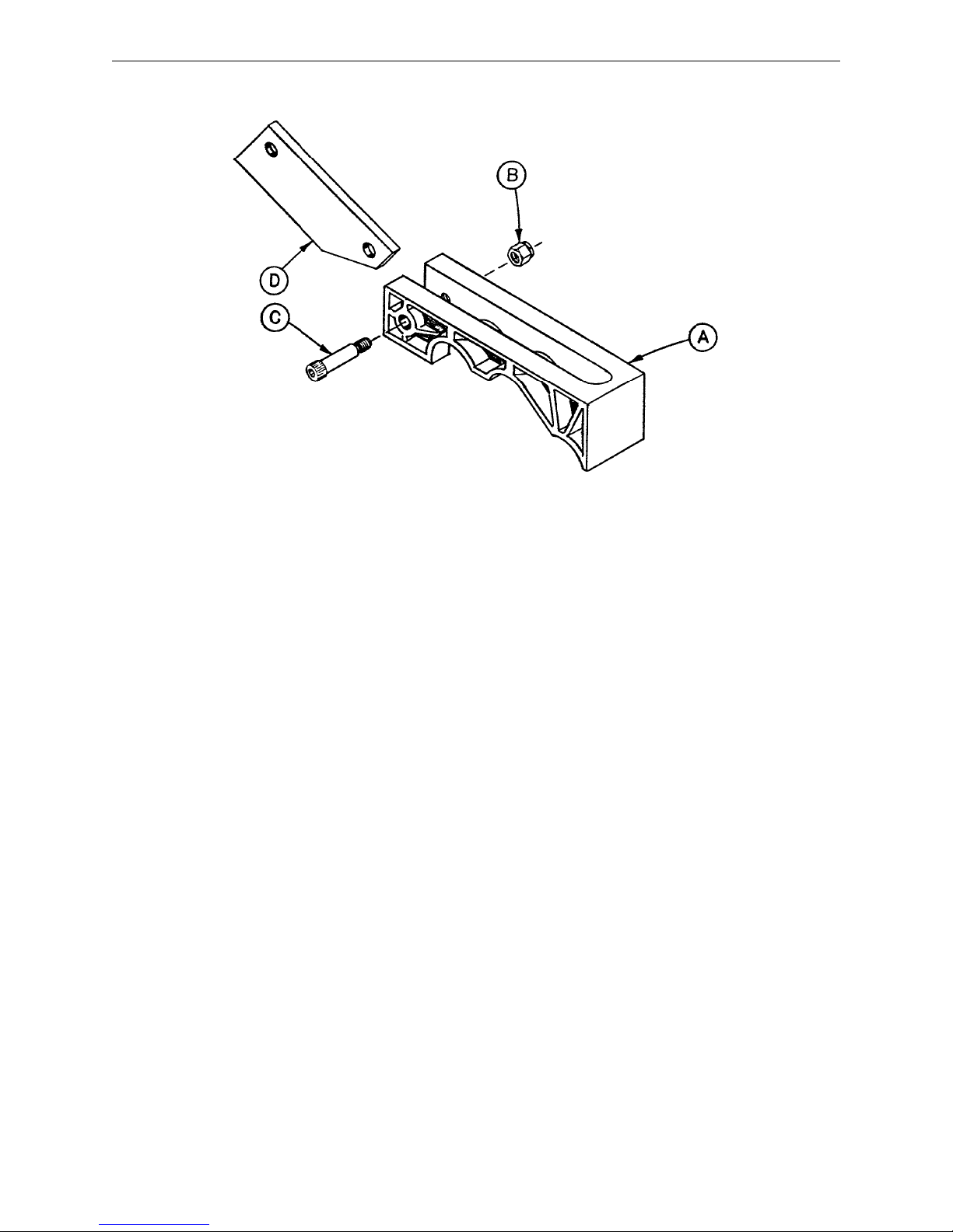
715–1–213 Brake Cam Assembly
Item Part No. Part Name Qty.
A 715–1–221 Brake Cam 1
B16–59 Fiberlock Nut 1
C8–21 Soc. Hd. Cap Screw 1
D 715–1–173 Brake Connecting Link 1
21

Notes
22
1010–90 Reduced Length Brake/Steer Base Option
Steering Lock Linkage Bar p/n 1000–10–62 (Ref.)
Collar w/Set Screw p/n 42–20 (Ref.)
Fifth Wheel Cam
p/n 715–1–161 (Ref.)
Item Part No. Part Name Qty.
A 1010–90–10 Brake Pedal Assembly 2
B 1010–90–24 Brake Bar 1
C 715–1–165 Actuator Plate Assembly 1
D26–35 Roll Pin 2
E26–13 Roll Pin 1
F8–17 Shoulder Bolt 1
G14–2 Nylon Washer 6
H16–2 Fiberlock Nut 2
J26–8 Roll Pin 1
K8–21 Shoulder Bolt 1
NOTE
This assembly pertains only to units equipped with the reduced length brake/steer option (for Surgi–lift clearance). The width of the brake/steer pedal will be 11 1/4 inches if the unit is equipped with this option. If the
pedal is wider than 11 1/4 inches, base assembly 715–1–250 or 716–1–251 should be referenced.
23
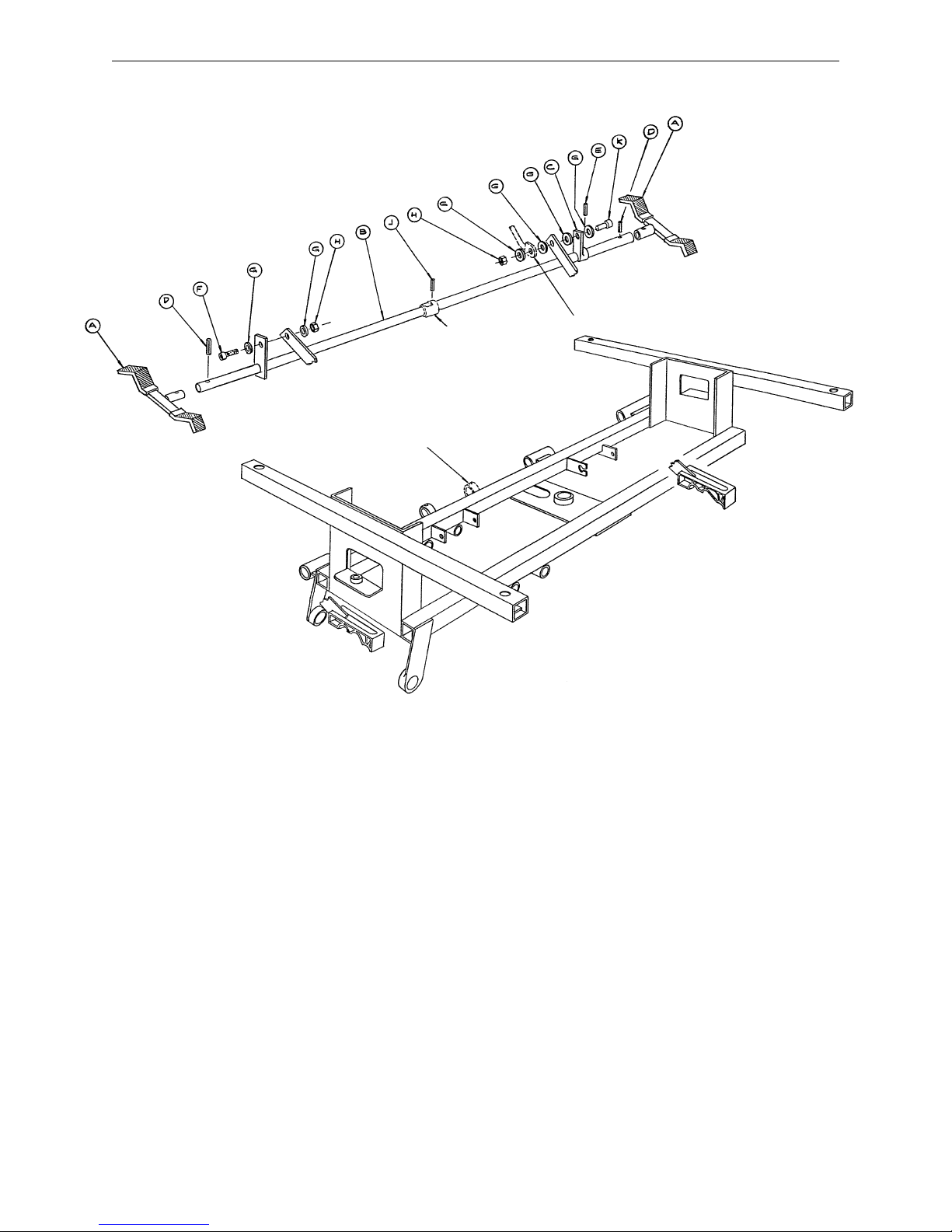
End Control Base Assembly (with Wheels and Brakes)
24
Note:
Parts and assemblies drawn with broken
lines are part of optional accessories.
Assembly part number 716–1–251
 Loading...