

Page 1

1488 HD 3-Chip Pendulum Camera
with Integrated Coupler
1488310130
Page 2

Page 3

Contents
Warnings and Cautions ....................................................... 1
Product Description and Intended Use ............................. 3
Indications/Contraindications ............................................................................3
Product Features ...................................................................................................... 4
Setup .................................................................................... 5
Operation ............................................................................. 7
Operating the Camera with a Light Source ....................................................7
Using the Camera Head Buttons ........................................................................8
Using the Touchscreen Interface........................................................................9
Performing the White-Balance Test ................................................................ 11
Adjusting the Focus ............................................................................................. 11
Rotating the Image .............................................................................................. 12
Reprocessing and Maintenance ....................................... 13
Using Sterile Drapes ............................................................................................ 20
Disposal .................................................................................................................... 20
Technical Specications .................................................... 21
Symbol Denitions ............................................................ 22
Page 4

Page 5

1
Warnings and Cautions
Please read this manual and follow its instructions carefully. The words
warning, caution, and note carry special meaning and should be carefully
reviewed:
Warning Indicates risks to the safety of the patient or user. Failure to
follow warnings may result in injury to the patient or user.
Caution Indicates risks to the equipment. Failure to follow cautions
may result in product damage.
Note: Claries the instructions or presents additional useful information.
An exclamation mark within a triangle is intended to alert the
user to the presence of important operating and maintenance
instructions in the manual.
A lightning bolt within a triangle is intended to warn of the
presence of hazardous voltage. Refer all service to authorized
personnel.
IMPORTANT SAFETY NOTICE: Before operating this device, please read this
operating manual thoroughly and carefully. When using this device with
a light source, re and/or severe injury may result to the patient, user, or
inanimate objects if the instructions in this manual are not followed.
All light sources can generate signicant amounts of heat (exceeding
41°C/106°F) at the scope tip, the scope light post, the light cable tip, and/or
near the light cable adapter. Higher levels of brightness from the light source
result in higher levels of heat. Always adjust the brightness level of the camera
and the monitor before adjusting the brightness level of the light source.
Adjust the brightness level of the light source to the minimum brightness
necessary to adequately illuminate the surgical site.
In addition, adjust the internal shutter of the camera higher in order to run
the light source at a lower intensity. Avoid touching the scope tip or the light
cable tip to the patient, and never place them on top of the patient, as doing
so may result in burns to the patient or user. In addition, never place the
scope tip, the scope light post, the light cable adapter, or the light cable tip on
the surgical drapes or other ammable material, as doing so may result in re.
Always place the light source in standby mode whenever the scope is
removed from the light cable or the device is unattended. The scope tip,
scope light post, light cable adapter, and light cable tip will take several
minutes to cool o after being placed in standby mode, and therefore may
still result in re or burns to the patient, user, or inanimate objects.
Page 6

2
Warnings
To avoid potential serious injury to the user and the patient and/or damage to
this device, please note the following warnings:
1. Must be a qualied physician to use this equipment.
2. Carefully unpack this device and check if any damage occurred during
shipment. If damage is detected, refer to the standard warranty.
3. Read this operating manual thoroughly, especially the warnings, and be
familiar with its contents before connecting and using this device.
4. Before using this device, read Stryker operating manual P18966 or
P18972 for warnings and other information about using the camera
system.
5. Test this equipment prior to a surgical procedure. This unit was fully
tested at the factory before shipment.
6. The camera head surface may exceed 41°C (106°F) in operating
conditions with high ambient temperatures and should be handled with
caution.
7. Pay close attention to the care, cleaning, disinfection, and sterilization
instructions in this manual. Any deviation may cause damage.
8. Never use the camera system in the presence of ammable or explosive
gases.
9. Always treat the camera system with care. The camera system contains
sensitive parts that are precisely aligned and may suer damage if
dropped or mistreated.
10. Do not disassemble any part of the camera head; doing so may break the
seals, causing leakage and/or electric shock.
11. Attempt no internal repairs or adjustments not specically detailed in this
operating manual.
12. Ensure that readjustments, modications, and/or repairs are carried out
by persons authorized by Stryker Endoscopy.
The warranty is void if any of these warnings are disregarded.
Page 7

3
Product Description and Intended Use
The Stryker 1488 HD 3-Chip Pendulum Camera Head with Integrated Coupler
(“Pendulum Camera”) is a high-denition camera used to produce still and
video images of endoscopic surgical applications. It is designed with a 90°
angle between the camera head and the scope to allow for easier access
during urology procedures. The Pendulum Camera also allows rotating the
camera head 360° to properly orient the video image.
The Pendulum Camera is used in conjunction with the 1488 HD 3-Chip
Camera Control Unit (1488010000 or 1488010001). For more information
about the camera console, refer to Stryker user guide P18966 or P18972.
Indications/Contraindications
The 1488 HD 3-Chip Pendulum Camera Head with Integrated Coupler is
indicated for use in general laparoscopy, nasopharyngoscopy, ear endoscopy,
sinuscopy, and plastic surgery wherevera laparoscope/endoscope/
arthroscope is indicated for use.
A few examples of the more common endoscopic surgeries are laparoscopic
cholecystectomy, laparoscopic hernia repair, laparoscopic appendectomy,
laparoscopic pelvic lymph node dissection, laparoscopically assisted
hysterectomy, laparoscopic and thorascopic anterior spinal fusion, anterior
cruciate ligament reconstruction, knee arthroscopy, shoulder arthroscopy,
small joint arthroscopy, decompression xation, wedge resection, lung
biopsy, pleural biopsy, dorsal sympathectomy, pleurodesis, internal mammary
artery dissection for coronary artery bypass, coronary artery bypass grafting
where endoscopic visualization is indicated and examination of the evacuated
cardiac chamber during performance of valve replacement.
The users of the camera are general surgeons, gynecologists, cardiac
surgeons, thoracic surgeons, plastic surgeons, orthopedic surgeons, ENT
surgeons and urologists.
There are no known contraindications.
Page 8
4
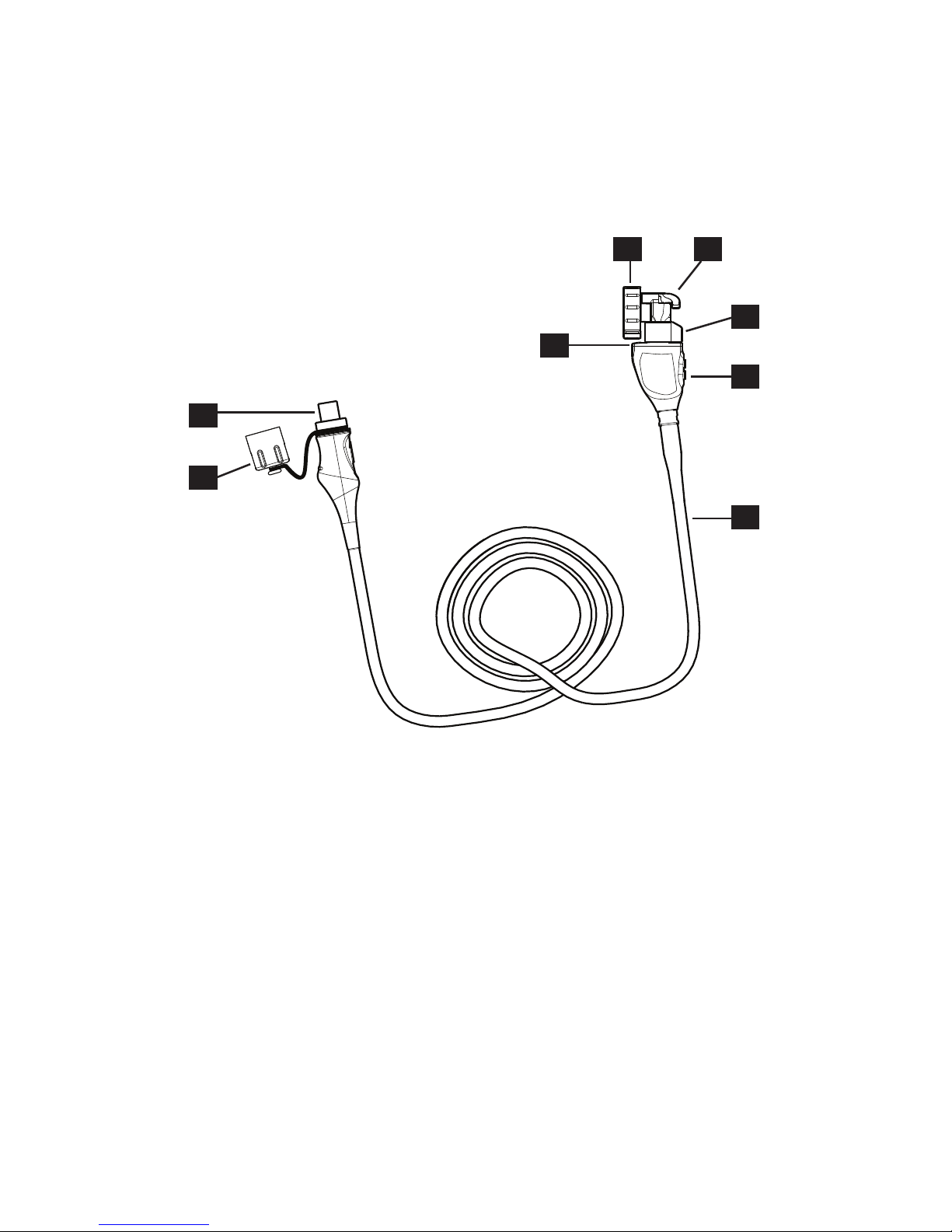
Product Features
The Pendulum Camera connects to the camera console and produces video
and photographic images, which it relays to the camera console. It features
several controls that are accessible through a button keypad located on the
top of the camera head (see the “Operation” section).
7
8
1
4
2 3
5
6
1. Image rotation
joint
Allows rotating the camera head 360° to reorient
the video image as needed
2. Endobody clamp Secures the scope to the camera head
3. Endobody brake Prevents rotation of the scope
4. Focusing knob Adjusts the focus of the camera head
5. Camera head
buttons
Provide camera controls
6. Camera cable The camera cable length is 10 feet (3.05 m)
7. Soaking cap Protects the cable connector during cleaning,
disinfection, and sterilization
8. Cable connector Connects the camera head to the camera console
Page 9
5
Setup
1. Set up the 1488 HD console according to the instructions provided in
Stryker user manual P18966 or P18972.
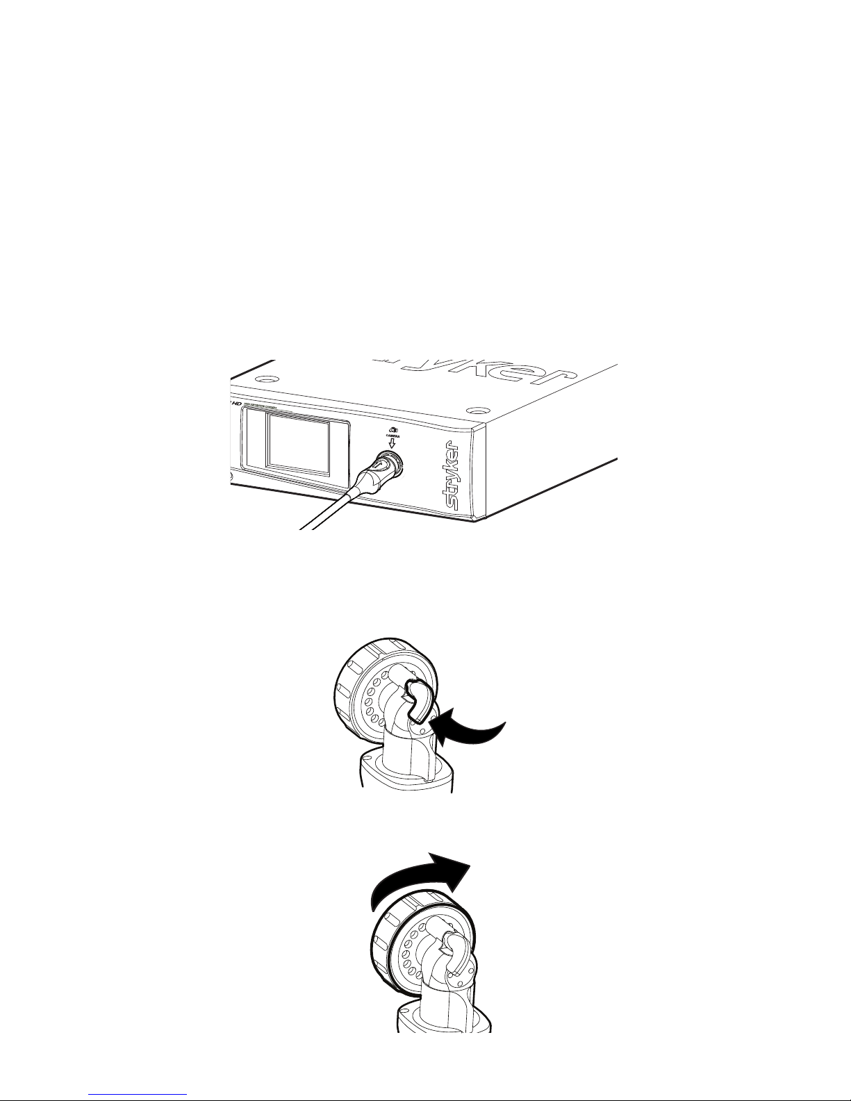
2. Connect the Pendulum Camera to the console.
• Unscrew the soaking cap from the cable connector if necessary.
• Align the blue arrow on the cable connector with the blue arrow
onthe camera-connector port on the front console panel.
• Push in the connector until it locks in place.
• (To unplug the Pendulum Camera from the console, grasp the
knobbed portion of the connector and pull straight out.)
3. Attach an endoscope to the Pendulum Camera.
• Remove the red dust cap if it is present.
• Lock the endobody brake by pushing it to the left.
• Twist the endobody clamp and hold it open.
Page 10

6
• Insert the endoscope into the endobody clamp.
• Release the endobody clamp. It will return to the original position
and secure the endoscope. (Twisting the endobody clamp in the
reverse direction can make it dicult to remove the endoscope.)
4. Attach a light cable from the light source to the light post on the
endoscope.
Page 11

7
Operation
Before using the Pendulum Camera in a surgical procedure,
ensure all system components have been set up according
to the instructions in the “Setup” section. Test all system
components to ensure proper function. Ensure that a video
image appears on all video monitors before beginning any
procedure.
Operating the Camera with a Light Source
IMPORTANT SAFETY NOTICE: Before operating this device,
please read this operating manual thoroughly and carefully.
When using this device with a light source, re and/or severe
injury may result to the patient, user or inanimate objects if the
instructions in this manual are not followed.
All light sources can generate signicant amounts of heat
(exceeding 41°C/106°F) at the scope tip, the scope light post,
the light cable tip, and/or near the light cable adapter. Higher
levels of brightness from the light source result in higher levels
of heat. Always adjust the brightness level of the camera and the
monitor before adjusting the brightness level of the light source.
Adjust the brightness level of the light source to the minimum
brightness necessary to adequately illuminate the surgical site.
In addition, adjust the internal shutter of the camera higher in
order to run the light source at a lower intensity. Avoid touching
the scope tip or the light cable tip to the patient, and never
place them on top of the patient, as doing so may result in burns
to the patient or user. In addition, never place the scope tip, the
scope light post, the light cable adapter, or the light cable tip
on the surgical drapes or other ammable material, as doing so
may result in re.
Always place the light source in standby mode whenever
the scope is removed from the light cable or the device is
unattended. The scope tip, scope light post, light cable adapter,
and light cable tip will take several minutes to cool o after
being placed in standby mode, and therefore may still result in
re or burns to the patient, user, or inanimate objects.
Page 12

8
Using the Camera Head Buttons
The camera head features a two-button keypad for controlling the Pendulum
Camera. These buttons are labeled P and W.
P (Picture) Button
The P button controls up to two functions of a remote video accessory.
Commonly this enables the user to capture images or start and stop
video recording. (See Stryker user guide P18966 or P18972 for connection
requirements.)
• Press the P button for less than two seconds to select Remote 1.
One beep will sound. When the camera is connected to a Stryker
digital capture console, this will capture a photo.
• Press the P button for more than two seconds to select Remote 2.
Two beeps will sound. When the camera is connected to a Stryker
digital capture console, this will start or stop video recording.
W (White-Balance) Button
The W button activates the white-balance function or the zoom-cycle
function.
• Press the W button for less than two seconds to activate the
zoom-cycle function. Each press will raise the zoom level in eight
steps. When the zoom level has reached its maximum, pressing the
button again will cycle the level back to the lowest setting.
• Press the W button for more than two seconds to activate the
white-balance function. White balancing will correct slight
color dierences that exist between dierent light sources or
endoscopes. See “Performing the White-Balance Test” below.
Page 13

9
Using the Touchscreen Interface
The touchscreen interface on the camera console provides controls for
adjusting or capturing the video image. The menus are described below.
Home Screen
The Home screen is
the default screen.
Use the buttons below
to choose surgical
specialties and operate
the camera head.
Scroll through preset camera settings designed for
surgical specialties. Choose from:
• Arthroscopy
• Cystoscopy
• ENT/Skull
• Flexi-Scope
• Hysteroscopy
• Laparoscopy
• Laser
• Microscope
• Standard
Press the camera button to capture a photo.
A single beep will sound to indicate that a signal
for capture/record has been sent to the digital
capture console.
Press the record button to record a video. Press
again to stop recording.
A double beep will sound to indicate that a signal
for capture/record has been sent to the digital
capture console.
Press and hold the WB button for two seconds
to activate white balance. See “Performing the
White-Balance Test” below for more detail.
A checkmark will appear on the button after the
white-balance test is complete.
Press the Menu button to navigate to the Menu
screen.
Page 14

10
Menu Screen
The Menu screen
provides options
for adjusting the
camera picture.
Press the plus or minus buttons to increase or decrease:
• Light (automatic-shutter light level)
• Zoom (magnication)
While adjusting Light or Zoom, a meter will briey
appear on the touchscreen to indicate each selection
level.
Press the Home button to return to the Home screen.
Page 15

11
Performing the White-Balance Test
Before each surgical procedure, perform the white-balance test to adjust the
camera’s perception of white so it can display other colors correctly.
1. Ensure that a scope and light source are attached to the camera, and that
the camera, light source and monitor are powered on.
2. Point the scope tip at several stacked white gauze pads, a white
laparoscopic sponge, or any clean white surface.
3. Look at the monitor and make sure there is no visible glare o of the
white surface of the image.
4. Press and hold the camera head W button (or “WB” on the touchscreen)
until the monitor displays the message “WHITE BALANCE IN PROGRESS.”
5. Continue pointing the scope at the white surface until the video monitor
displays the message “WHITE BALANCE COMPLETE.” The video picture
may change color. If you cannot achieve an acceptable white balance,
refer to the “Troubleshooting” section in the camera console user guide
P18966 or P18972.
Adjusting the Focus
Slide the focusing knob to the left or right to adjust the focus.
Page 16

12
Rotating the Image
Rotate the camera head at the image rotation joint to reorient the image as
needed. The camera head will rotate 360° independently of the scope.
Page 17

13
Reprocessing and Maintenance
These reprocessing instructions are provided in accordance with ISO 17664,
AAMI TIR12, AAMI ST79, and AAMI ST81. While they have been validated by
Stryker as being capable of preparing the device for re-use, it remains the
responsibility of the processor to ensure that the reprocessing as actually
performed, using equipment, materials, and personnel in the reprocessing
facility, achieves the desired result. This normally requires validation and
routine monitoring of the process. Stryker recommends users observe these
standards when reprocessing medical devices.
Warnings
• This device must be cleaned and sterilized prior to the rst use and
after every subsequent use.
• Use only the sterilization cycles outlined in this document. Using
unspecied sterilization cycles may damage the device or result in
incomplete sterilization.
• Separate the camera and scope prior to cleaning, disinfection, or
sterilization.
• Wear appropriate protective equipment: gloves, eye protection, etc.
Cautions
• Always install the soaking cap prior to processing the camera. Failure
to properly tighten the soaking cap will corrode the connector pins
and void the warranty.
• Inspect the camera cable for cuts and breaks before soaking in any
uid. Return any damaged camera to Stryker for service.
• Never soak the camera in the same tray with sharp instruments.
• Do not use brushes or pads with metal or abrasive tips during
manual cleaning, as permanent scoring or damage could result.
• To minimize galvanic corrosion, avoid soaking dissimilar metals in
close proximity.
• The Pendulum Camera is not autoclavable. Steam sterilizing camera
heads that are not marked autoclave will result in product damage.
• Allow the camera head to cool before connecting it to the console.
Connecting the camera head while it is hot may result in system
error.
• When using Steris® liquid chemical sterilization, remove the camera
head from the chamber once sterilization is complete, or moisture
may condense inside the camera head and cause display defects.
Page 18

14
Limitations on Reprocessing
• Do not cross-sterilize the device. Using multiple sterilization
methods may signicantly reduce the performance of the device.
• Prolonged sterilization via Ethylene Oxide or Sterrad®100NX™ may
degrade the product appearance.
• Do not leave the device in solutions longer than necessary. This may
accelerate normal product aging.
• Proper processing has a minimal eect on this device. End of life is
normally determined by wear and damage due to use.
• Only dry the device with the automated washing system parameters
specied below. Additional drying time or other setups can cause
product damage.
• Damage caused by improper processing is not covered by the
warranty.
Instructions
Point of Use
• Wipe excess soil from the device using disposable paper towels.
• If an automated reprocessing method will be used, rinse any
channels inthe device with 50 mL of sterile distilled water
immediately after use.
Containment and Transportation
• Reprocess the device as soon as reasonably practical following use1.
• Transport the device in a tray to avoid damage.
1
A 30 minute wait time was used during cleaning validation.
Preparation for Cleaning
1. Disassemble the scope from the coupler and camera head.
2. Prepare an enzymatic detergent according to the manufacturer’s
recommendations (one ounce per gallon of tap water at 35–40 °C)2.
3. Wipe the entire device with the detergent, using a clean cloth.
4. Immerse the device in the detergent. Using a syringe, inject any inside
regions of the device with 50 mL of the detergent to ensure all parts of
the device are reached.
5. Soak the device in the detergent for a minimum of 15 minutes.
2
ENZOL® Enzymatic Detergent is validated for cleaning ecacy.
Page 19

15
Cleaning: Manual
1. Brush
• Prepare a fresh solution of enzymatic detergent according to the
manufacturer’s recommendations (one ounce per gallon of tap
water at35–40 °C).
• Thoroughly brush the exterior of the device with a soft-bristled
brush, focusing on any mated or rough surfaces.
• Using a syringe, inject any lumen or mated surface a minimum
ofvetimes with 50 mL of the detergent.
• Brush any lumens a minimum of ve times from each end, using
anappropriate bottle brush.
• Brush any movable parts in all extreme positions.
2. Rinse
• Rinse the device with reverse osmosis/de-ionized (RO/DI) water at
ambient temperature until all detergent residue is removed. Flush
any lumens or mated surfaces a minimum of ve times. Once all
detergent residue is removed, continue to rinse for a minimum of 30
seconds.
• Drain excess water from the device and dry it using a clean cloth
orpressurized air.
• Visually inspect the device for cleanliness, paying close attention
tohard-to-reach areas. If visible soil remains, repeat steps 1 and 2.
3. Soak
• Prepare a non-enzymatic detergent according to the manufacturer’s
recommendations (0.125 ounces per gallon of tap water at 35–
40°C)3.
• Fully immerse the device and use a syringe to inject any lumens and
mated surfaces with 50 mL of the detergent.
• Soak the device for a minimum of 15 minutes.
4. Brush
• Thoroughly brush the exterior of the device using a soft-bristled
brush.
• Using a syringe, inject 50 mL of the detergent into any cannulae,
lumens, or mated surfaces a minimum of ve times.
• Brush any lumens a minimum of ve times from each end, using an
appropriate bottle brush.
• Actuate the device, brushing around any movable parts in all
extreme positions.
Page 20

16
5. Rinse
• Thoroughly rinse the device with RO/DI water until all detergent
residue is removed. Flush any lumens or crevices a minimum of ve
times. Once all detergent residue is removed, continue to rinse for a
minimum of 30 seconds.
• Drain the excess water from the device and dry it using a clean cloth
orpressurized air.
3
Prolystica® 2x Neutral Detergent is validated for cleaning ecacy.
Cleaning: Automated
1. Brush
• Using a syringe, inject 50 mL of the enzymatic detergent (from
the “Preparation for Cleaning” section) into any lumen and mated
surface aminimum of one time.
• Brush from both ends of any lumens a minimum of ve times, using
an appropriate bottle brush.
2. Rinse
• Rinse the device with RO/DI water at ambient temperature
until there is no visible detergent residue. Continue to rinse for
a minimum of 30seconds after all detergent residue has been
removed.
• Place the device in the washer on an incline to facilitate drainage.
3. Automated wash
• Program the washer using the following parameters:
Phase Recirculation
Time
Water
Temperature
Detergent Type and
Concentration
(if applicable)
Pre Wash 2 minutes Cold tap
water
N/A
Enzyme
Wash
2 minutes Hot tap water Enzymatic Detergent
Wash 1 2 minutes Set point
(66 ˚C)
Non-enzymatic
Detergent
4
Rinse 1 2 minutes Hot tap water N/A
Dry Phase 7 minutes 115 ˚C N/A
Page 21

17
• If necessary, use pressurized air to aid in drying. Visually inspect each
device for cleanliness.
4
Prolystica® 2x Neutral Detergent is validated for cleaning ecacy.
Low Level Disinfection (optional)
1. Clean and prepare the camera head and cable as recommended in this
user guide. Ensure the soaking cap is installed.
2. Disinfect the device in a disinfecting solution that has one of the
following active Ingredients:
• ≥ 2.4% glutaraldehyde5 with a minimum soaking time of 45 min at
25°C
• ≥ 3.4% glutaraldehyde6 with a minimum soaking time of 20 min at
25°C
• ≥ 0.55% ortho-phthalaldehyde7 with a minimum soaking time of
12min at 25°C.
3. Prepare the disinfecting solution according to the manufacturer’s
instructions.
4. Per manufacturer’s recommendations, immerse the device, lling
all lumens, in the disinfecting solution for the required time at the
appropriate temperature.
5. Dry all parts with a lint-free towel immediately after rinsing.
5
CIDEX Activated® is validated for disinfection ecacy.
6
CIDEX Plus® is validated for disinfection ecacy.
7
CIDEX® OPA is validated for disinfection ecacy.
Drying
• For automated drying, use the drying cycle provided with the
washer/disinfector.
• For manual drying, use a lint-free cloth.
• Dry any lumens with compressed air.
Maintenance, Inspection, and Testing
• Inspect the device on a continual basis. If a problem is observed or
suspected, the device should be returned for repair.
• Inspect all components for cleanliness. If uid or tissue buildup is
present, repeat the above cleaning and disinfection procedures.
• Inspect the camera cable for cuts and breaks. Return any damaged
camera to Stryker for service.
Page 22

18
Packaging
N/A
Sterilization
After performing the cleaning instructions specied above, perform one of
the following sterilization cycles.
Ethylene Oxide (EO)
1. Clean and prepare the camera head and cable as recommended in this
user guide. Ensure the soaking cap is installed.
2. If using a sterilization tray (optional), follow any additional instructions
provided with the tray. Use only trays that are compatible with EO.
3. Double wrap the camera head and cable (or tray) prior to sterilization.
4. Sterilize the camera head and cable using the parameters below.
5. Allow the camera head, cable, coupler, and scope to completely dry
before reassembly. Any moisture on the threads will cause the camera
and coupler windows to fog during use.
Preconditioning parameters
Temperature 55 °C (131 °F)
Chamber Humidity 70% RH
Vacuum Set Points 1.3 psia
Time 30 minutes
Exposure
Concentration (100% EO) 725 mg/L
Temperature 55 ± 2 °C (131 ± 5 °F)
Time 1 hour
Chamber Humidity 70% RH (50–80%) ± 5%
Aeration parameters
Aeration Time 12 hours
Temperature 35–54 °C (95–129 °F)
Page 23

19
Steris System 1 / 1E / 1 Plus / 1 Express
Note: Steris System 1®, System 1® Plus, and System 1® Express are
not intended for use in the United States.
1. Clean and prepare the camera head and cable as recommended in this
user guide. Ensure the soaking cap is installed.
2. Following the instructions of the manufacturer, sterilize the camera
head and cable using one of the Steris systems below with the
appropriate sterilant:
• System 1 with Steris 20 Sterilant
• System 1E® with S40™ Steris Sterilant
• System 1 Plus with S40 Sterilant
• System 1 Express with S40 Sterilant
3. Remove the camera head and cable from the Steris chamber once
sterilization is complete, or moisture may condense inside the camera
head and cause display defects.
4. Allow the camera head, cable, coupler, and scope to completely dry
before reassembly. Any moisture on the threads will cause the camera
and coupler windows to fog during use.
Steris/Amsco V-PRO
1. Clean and prepare the camera head and cable as recommended in this
user guide. Ensure the soaking cap is installed.
2. If using a sterilization tray (optional), follow any additional instructions
provided with the tray. Use only trays that are approved for sterilization
with Steris/Amsco® V-PRO®.
3. Double wrap the camera head and cable (or tray) prior to sterilization.
4. Sterilize the device using the V-PRO maX Sterilizer (Non-Lumen or
Standard cycle), the V-PRO 1 Plus Sterilizer (Non-Lumen or Standard
cycle), or the V-PRO 1 Sterilizer (Standard cycle).
5. Allow the camera head, cable, coupler, and scope to completely dry
before reassembly. Any moisture on the threads will cause the camera
and coupler windows to fog during use.
Page 24

20
Sterrad
1. Clean and prepare the camera head and cable as recommended in this
user guide. Ensure the soaking cap is installed.
2. If using a sterilization tray (optional), follow any additional instructions
provided with the tray. Use only trays that are compatible with Sterrad.
Not all sterilization trays are compatible with Sterrad systems.
Using an incompatible tray may result in incomplete device
sterilization. Consult the instructions that came with your
sterilization tray to determine which sterilization method is
compatible with your tray and devices. If a compatible tray
is not available, the devices can be double wrapped prior to
using the Sterrad system.
3. Double wrap the camera head and cable (or tray) prior to sterilization.
4. Sterilize the camera head and cable following the instructions of the
manufacturer, using the Sterrad 100S, NX™, or 100NX Sterilization
System. Select the standard cycle.
5. Allow the camera head, cable, coupler, and scope to completely dry
before reassembly. Any moisture on the threads will cause the camera
and coupler windows to fog during use.
Storage
Never store the device in a non-ventilated, humid environment such as a
carrying case. This may present an infection control risk.
Using Sterile Drapes
Using sterile drapes will ensure maximum longevity of your 1488 HD
Camera Head. For best results, follow the instructions provided by the drape
manufacturer.
Disposal
This product contains electrical waste or electronic equipment.
It must not be disposed of as unsorted municipal waste and
must be collected separately in accordance with applicable
national or institutional related policies relating to obsolete
electronic equipment.
The 1488 HD must be disposed of according to local laws and hospital
practices.
Page 25

21
Technical Specications
Imaging System 1/3″ Progressive Scan CMOS
High Denition
Operating Conditions Temperature: 10–30 °C
Relative Humidity: 25–75%
Transport and Storage
Conditions
Temperature: -18–60 °C
Relative Humidity: 15–90%
Total Shipping Weight 1.5 lb (0.680 kg)
Dimensions Camera Head Cable:
10.3 ft (3.15 m) sealed cable
20.7 ft (6.30 m) cable extension available
Classication Type BF Applied Part
Ingress Protection, IPX7—Protected against
the eects of temporary immersion in water
Please contact your local Stryker Endoscopy sales representative for
information on changes and new products.
Page 26

22
Symbol Denitions
In addition to the cautionary symbols already listed, other symbols found on
the 1488 HD Camera and in this manual have specic meanings that clarify
the proper use and storage of the 1488 HD Camera. The following list denes
the symbols associated with this product:
Federal law (USA)
restricts this device to
use by, or on order of, a
physician
Caution (consult
instructions for use)
Rotate endobody
clamp in indicated
direction to detach
endoscope
Product is
manufactured in the
USA
Date of manufacture
Legal manufacturer
Device is shipped nonsterile and must be
sterilized before use
Product catalog
number
Serial number
The device meets
requirements for safety
and eectiveness set
forth in MDD 93/42/
EEC
Stryker European
representative
Type BF applied part
Device recycling code
(applicable in China)
This product contains
electrical waste or
electronic equipment.
It must not be disposed
of as unsorted
municipal waste and
must be collected
separately.
Temperature limitation
Relative humidity
limitation
Page 27

Page 28

Stryker Endoscopy
5900 Optical Court
San Jose, CA 95138 USA
1.800.624.4422
U.S. Patents: www.stryker.com/patents
Stryker Corporation or its divisions or
other corporate aliated entities own,
use or have applied for the following
trademarks or service marks: the
Stryker logo. All other trademarks are
trademarks of their respective owners
or holders.
2016/04
WCR: None
 Loading...