

Page 1
English
Français
Deutsch
Italiano
Português
Español
Nederlands
Dansk
Suomi
Norsk
Svenska
Polski
Ελληνικά
中文
日本語
한국어
User Guide
1188HD
Video Camera
REF 1188-010-000
1188-210-105
1188-410-105
1188-710-105
Page 2

Page 3

English: 1188HD Video Camera .............................................EN-1
Français: 1188HD Caméra vidéo.......................................... FR-45
Deutsch: 1188HD Videokamera ...........................................DE-93
Italiano: 1188HD Videocamera.............................................IT-141
Português: 1188HD Câmara de Vídeo ............................... PT-189
Español: 1188HD Vídeocámara.......................................... ES-237
Nederlands: 1188HD videocamera .................................... NL-287
Dansk: 1188HD Videokamera ............................................DA-335
Suomi: 1188HD Videokamera ..............................................FI-381
Norsk: 1188HD Videokamera............................................ NO-427
Svenska: 1188HD Videokamera......................................... SV-473
Polski: 1188HD Kamera wideo........................................... PL-519
Ελληνικά: 1188HD Βιντεοκάμερα ........................................EL-567
中文 : 1188HD 摄像机...................................................... CHS-617
日本語 : 1188HD ビデオカメラ ...........................................JP-657
한국어 : 1188HD 비디오 카메라 .........................................KO-705
Page 4

Page 5

EN-1
1188HD
Video Camera
User Guide
Contents
Warnings and Cautions ......................................... 3
Symbol Definitions ............................................................................ 5
Product Description and Intended Use ................. 7
Indications/Contraindications ........................................................... 7
Camera Console ............................................................................... 8
Camera Head .................................................................................. 10
C-Mount Coupler ............................................................................ 11
Setup and Interconnection ................................. 12
Setting Up the Console ................................................................... 12
Setting Up the Camera Head .......................................................... 17
Setting Up the Coupler ................................................................... 17
Operation Instructions ....................................... 19
Powering the Camera On/Off ......................................................... 19
Using the Camera Buttons ............................................................. 19
Selecting the Display Language ..................................................... 21
Using the Configuration Menu ........................................................ 22
Controlling Remote Video Accessories .......................................... 22
Using the SFB Serial Interface ........................................................ 23
Using the DVI Fiber Outputs ........................................................... 23
Operating the Camera with a Light Source .................................... 24
Troubleshooting ................................................. 25
Cleaning and Sterilization .................................. 28
Cleaning the Camera Console ........................................................ 28
Reprocessing the Camera Head ..................................................... 28
User Maintenance ........................................................................... 36
Page 6

EN-2
Technical Specifications .................................... 37
Electromagnetic Compatibility ........................................................ 39
Warranty ............................................................ 43
Service and Claims ............................................. 44
Page 7
EN-3
Warnings and Cautions
Please read this manual and follow its instructions carefully. The words warning,
caution, and note carry special meanings and should be carefully reviewed:
Warning The personal safety of the patient or physician may be
involved. Disregarding this information could result in injury
to the patient or user.
Caution Special service procedures or precautions must be followed to
avoid damaging the instrument.
Note Special information to make maintenance easier or important
information more clear.
An exclamation mark within a triangle is intended to alert the
user to the presence of important operating and maintenance
instructions in the literature accompanying the product.
A lightning bolt within a triangle is intended to warn of the
presence of hazardous voltage. Refer all service to authorized
personnel.
IMPORTANT SAFETY NOTICE:
Before operating this device, please read
this operating manual thoroughly and carefully. When using this device with
a light source, fire and/or severe injury may result to the patient, user or
inanimate objects if the instructions in this manual are not followed. All light
sources can generate significant amounts of heat at the scope tip, the scope
light post, the light cable tip, and/or near the light cable adapter. Higher levels
of brightness from the light source result in higher levels of heat. Always
adjust the brightness level of the camera and the monitor before adjusting the
brightness level of the light source. Adjust the brightness level of the light
source to the minimum brightness necessary to adequately illuminate the
surgical site. In addition, adjust the internal shutter of the camera higher in
order to run the light source at a lower intensity. Avoid touching the scope tip
or the light cable tip to the patient, and never place them on top of the patient,
as doing so may result in burns to the patient or user. In addition, never place
the scope tip, the scope light post, the light cable adapter, or the light cable tip
on the surgical drapes or other flammable material, as doing so may result in
fire. Always place the light source in standby mode whenever the scope is
removed from the light cable or the device is unattended. The scope tip, scope
light post, light cable adapter, and light cable tip will take several minutes to
cool off after being placed in standby mode, and therefore may still result in
fire or burns to the patient, user, or inanimate objects.
Page 8

EN-4
To avoid potential serious injury to the user and patient, and/or damage to this
device, the user must:
1. Carefully unpack this unit and check if any damage occurred during
shipment. If damage is detected, refer to the “Service and Claims”
section of this manual.
2. Read this operating manual thoroughly, especially the warnings, and be
familiar with its contents before connecting and using this equipment.
3. Be a qualified physician, having complete knowledge of the use of this
equipment.
4. Test this equipment prior to a surgical procedure. This unit was fully
tested at the factory before shipment.
5. Never use this equipment in the presence of flammable or explosive
gases.
6. The camera head surface may exceed 41°C (106°F) in operating
conditions with high ambient temperatures and should be handled with
caution.
7. Avoid dissembling any part of the camera head, as doing so may break
the seals, causing leakage and/or electric shock.
8. Avoid removing covers on the control unit, as doing so may cause
damage to electronics and/or electric shock.
9. To avoid risk of electric shock, this equipment must only be connected
to a supply mains with protective earth.
10. Attempt no internal repairs or adjustments not specifically detailed in
this operating manual.
11. Pay close attention to the care and cleaning instructions in this manual.
Any deviation may cause damage.
12. The camera head and coupler are shipped non-sterile. Clean and
sterilize these components prior to first use and after every subsequent
use. Follow the cleaning, disinfection, and sterilization instructions
provided in these instructions.
13. Never sterilize the camera console, because the delicate electronics can
not withstand this procedure.
14. Never autoclave a camera head unless it is marked
AUTOCLAVABLE.
Autoclaving regular camera heads will result in permanent device
damage for which Stryker will not be responsible.
15. Disconnect the control unit from the electrical outlet when inspecting
the fuses.
Page 9

EN-5
16. Before each use, check the outer surface of the endoscope to ensure that
there are no rough surfaces, sharp edges, or protrusions.
17. Avoid dropping the camera system. The camera system contains
sensitive parts that are precisely aligned.
18. Ensure that readjustments, modifications, and/or repairs are carried out
by persons authorized by Stryker Endoscopy. No modification of this
equipment is allowed.
19. Ensure that the electrical installation of the relevant operating room
complies with the NEC and CEC guidelines.
20. Do not position the console so that it is difficult to disconnect the power
cord from the supply mains.
The warranty is void if any of these warnings are disregarded.
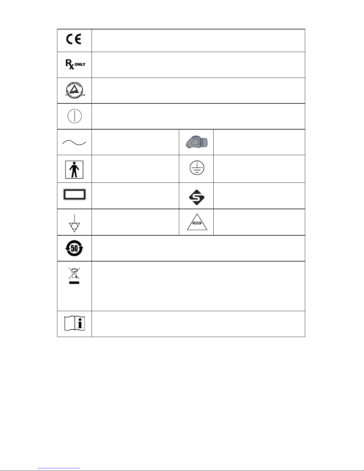
Symbol Definitions
In addition to the cautionary symbols already listed, other symbols found on the
1188HD Camera and in this manual have specific meanings that clarify the
proper use and storage of the 1188HD Camera. The following list defines the
symbols associated with this product.
Refer to instruction manual.
Caution (consult instructions for use)
Cameras, couplers, and camera extension cable are shipped nonsterile and must be sterilized before use
Humidity range Legal manufacturer
Pressure range Date of manufacture
Temperature range Serial number
Country of origin Catalogue number
Stryker European representative
Page 10
EN-6
Device meets requirements for safety and effectiveness set forth in
MDD 93/42/EEC
Federal law (USA) restricts this device to use by, or on order of, a
physician
Denotes compliance to CAN/CSA C22.2 No 601.1 and UL 60601-1
Power on/off (alternates when button is pushed)
Alternating current
1188 camera head
connection
Type BF applied part
Protective ground earth
Class 1 laser product
FireWire
Equipotentiality
Fuse rating
Device recycling code (applicable to China)
This symbol indicates that the waste disposal of electrical and
electronic equipment must not be disposed as unsorted municipal
waste and must be collected separately. Please contact the
manufacturer or other authorized disposal company to
decommission your equipment.
Consult instructions for use
CLASS 1 LASER
PRODUCT
APPAREIL A LASER DE
CLASSE 1
Page 11

EN-7
Product Description and Intended Use
The Stryker Endoscopy 1188HD Medical Video Camera is a high-definition
camera used to capture still and video images of endoscopic surgical applications.
The 1188HD Medical Video Camera consists of three main components:
• Camera console (P/N 1188-010-000)
• Camera head (P/N 1188-210-105 45° cable; 1188-410-105
autoclavable; 1188-710-105 0° cable)
• C-mount coupler (P/N 1188-020-122; 1188-410-110 autoclavable)
The 1188HD also comes with various connection cables which, like the other
components, can be purchased together or separately.
Part numbers 1188-210-105 and 1188-710-105 are not intended for sale in the
European Union and do not bear a CE mark.
Warning Federal law (United States of America) restricts this device to
use by, or on the order of, a physician.
Indications/Contraindications
The 1188HD Camera is indicated for use in general laparoscopy,
nasopharyngoscopy, ear endoscopy, sinuscopy, and plastic surgery wherever a
laparoscope/endoscope/arthroscope is indicated for use. A few examples of the
more common endoscopic surgeries are laparoscopic cholecystectomy,
laparoscopic hernia repair, laparoscopic appendectomy, laparoscopic pelvic
lymph node dissection, laparoscopically assisted hysterectomy, laparoscopic and
thorascopic anterior spinal fusion, anterior cruciate ligament reconstruction,
knee arthroscopy, shoulder arthroscopy, small joint arthroscopy, decompression
fixation, wedge resection, lung biopsy, pleural biopsy, dorsal sympathectomy,
pleurodesis, internal mammary artery dissection for coronary artery bypass,
coronary artery bypass grafting where endoscopic visualization is indicated and
examination of the evacuated cardiac chamber during performance of valve
replacement. The users of the camera are general surgeons, gynecologists, cardiac
surgeons, thoracic surgeons, plastic surgeons, orthopedic surgeons, ENT
surgeons and urologists.
There are no known contraindications.
Page 12
EN-8
Camera Console
The camera console or Camera Control Unit (CCU) is the control center for the
1188HD Medical Video Camera and processes the video and photographic
images captured during the surgical procedure. The console front panel features
controls for adjusting the enhancement level, light level, zoom, and white balance.
The front panel allows selection of surgical specialty settings that optimize
camera performance for specific surgical procedures. The front panel also allows
activation of remote outputs.
The rear panel provides ports for connecting the 1188HD Camera to viewing and
recording equipment, such as video monitors, the SDC Ultra, or photo printers.
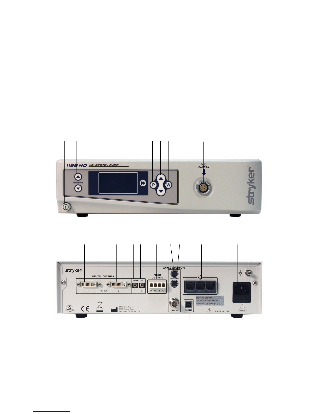
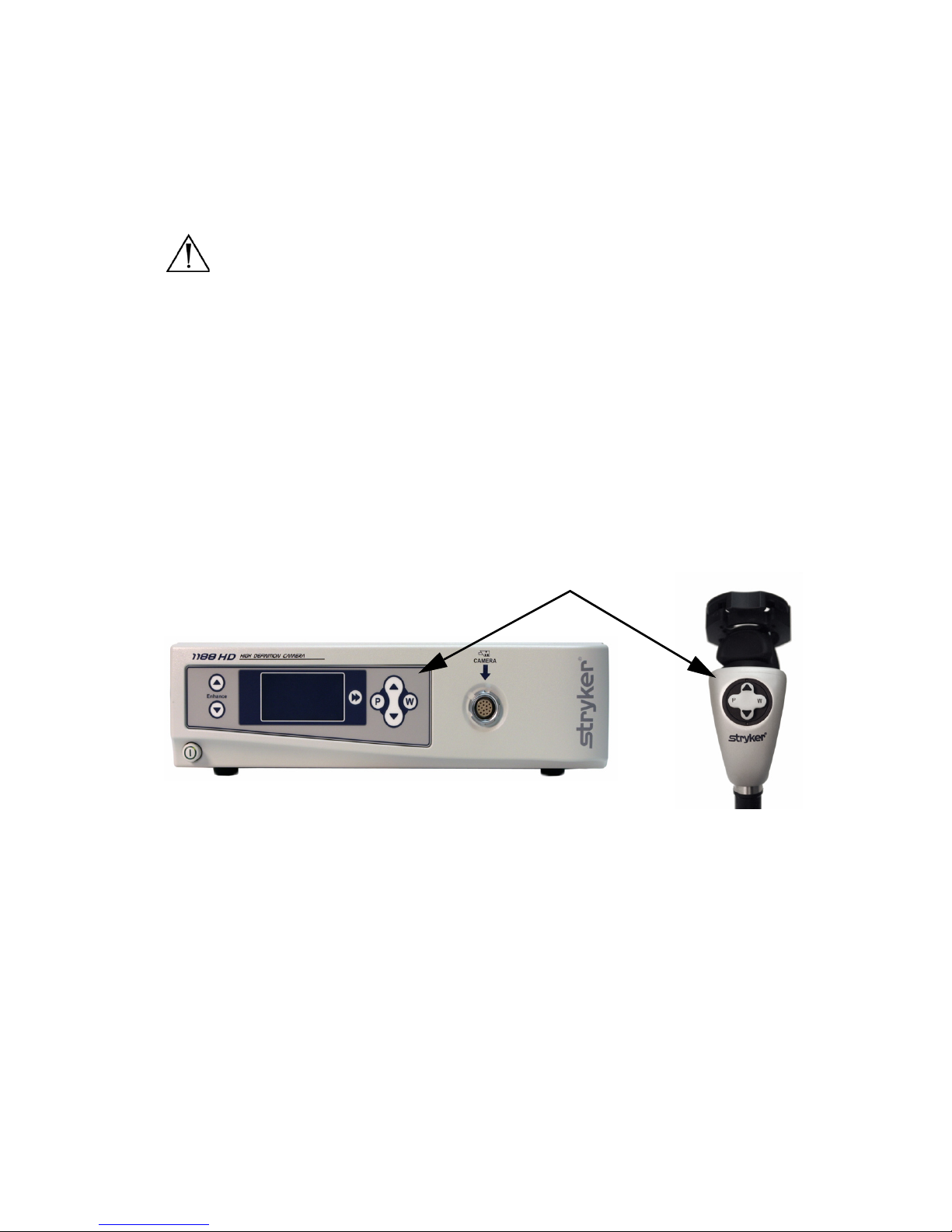
The features of the front and rear panels are listed in Figure 1.
Figure 1: 1188HD Camera console, front (top) and rear (bottom) panels
1. Power Switch: Powers the camera on and off
2. Enhance Buttons: Increase or decrease image sharpness
3. Specialty Screen: Displays which surgical preset setting has been
selected
91110 12 13 14 16 17 1815
192021
12 3 4567 8
Page 13

EN-9
4. Specialty Button: Selects different surgical settings
5. P Button: Controls image (picture) capture via remotes 1 and 2
6. Up and Down Arrow Buttons: Controls image light or zoom level
7. W Button: Controls white balance and image light or zoom level
8. Camera Connector: Connects to the 1188HD Camera Head
9. DVI Out 1: Digital video output
10. DVI Out 2: Digital video output
11. Remote Out 1: Connects to a video accessory remote switch
12. Remote Out 2: Connects to a video accessory remote switch
13. Fiber Outputs (optical): DVI output for connection to Lucent
connector fibers
14. S-Video 1 Out: Analog video output
15. S-Video 2 Out: Analog video output
16. SFB Connectors: Enables FireWire connection with Stryker FireWire
devices. Provides connection for remote diagnoses and future software
upgrades.
17. AC Power Inlet: Connects to a separable power cord, which can be used
for mains isolation
18. Equipotential Ground Plug: Connects to a potential equalization
conductor. The resulting medical electrical system shall follow all
applicable IEC 60601-1 requirements.
19. Fuse Panel: Contains two 1.6A 250V (slow blow, high breaking capacity
1500A) fuses
20. SIDNE® Port: Connects to the SIDNE® Console to enable voice
operation and/or graphic tablet control
21. Composite Out: Analog video output
Page 14
EN-10
Camera Head
The camera head connects to the camera console and captures video and
photographic images, which it relays to the camera console. It features several
controls that are accessible through a button keypad located on the top of the
camera head (see the “Operation Instructions” section of this manual).
Figure 2 below lists the features of the camera head.
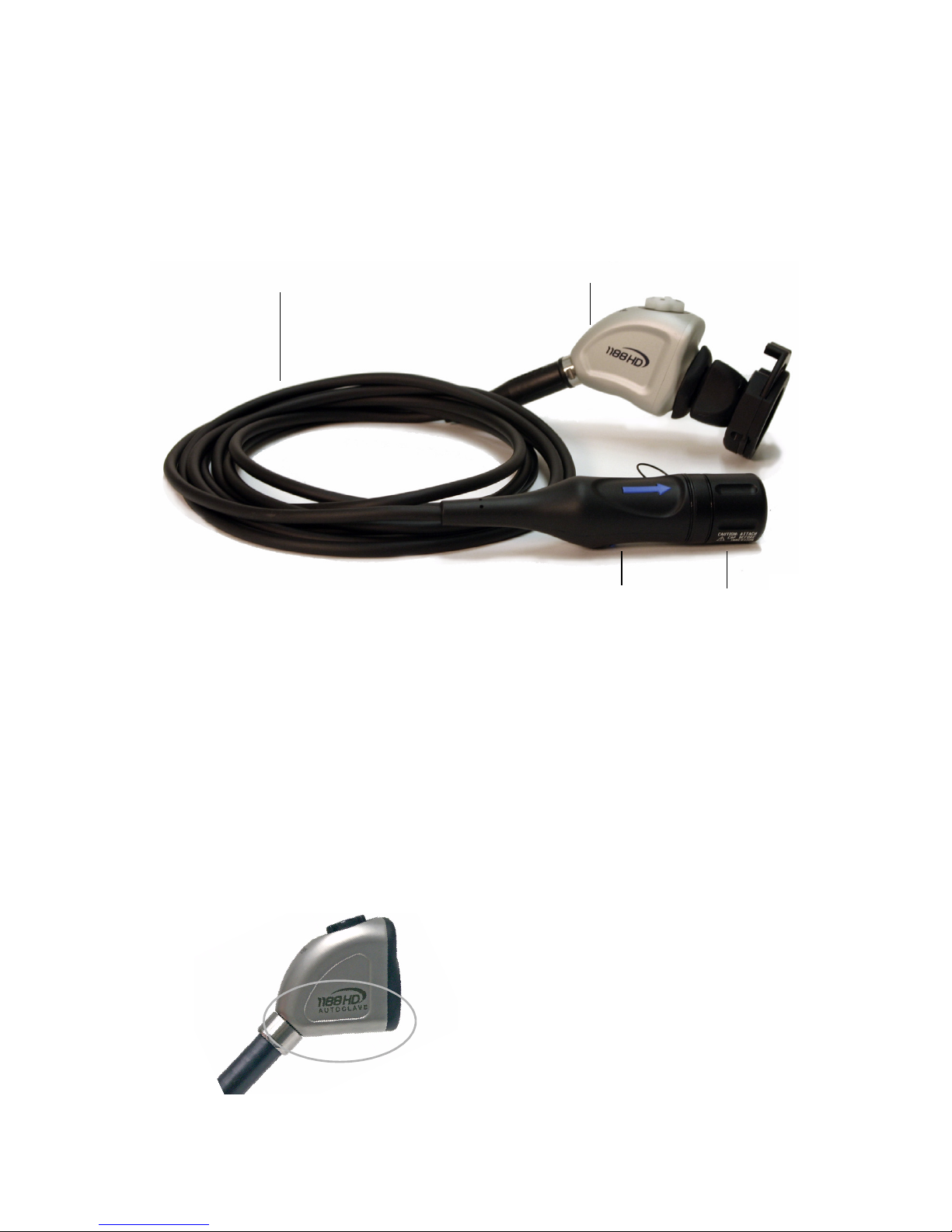
Figure 2: 1188HD Camera Head
1. Camera Cable
2. Camera Head: Captures photographic and video images, provides
camera controls, and connects with a focusing coupler
3. Soaking Cap: Protects the cable connector during cleaning and
sterilization
4. Cable Connector: Connects the camera head to the camera console
The camera head is available in autoclavable and non-autoclavable models:
Autoclavable (1188-410-105)
marked
AUTOCLAVE
Non-autoclavable
1188-210-105 (45° cable) and
1188-710-105 (0° cable)
12
34
Page 15
EN-11
C-Mount Coupler
The C-Mount coupler threads onto the face of the camera head, enabling a scope
to be attached to the camera. It provides a focusing ring to adjust image
sharpness.
The features of the coupler are listed in Figure 3 below. Additional instructions
are available in the “1188 C-Mount Coupler User Guide” (P/N 1000-400-905).
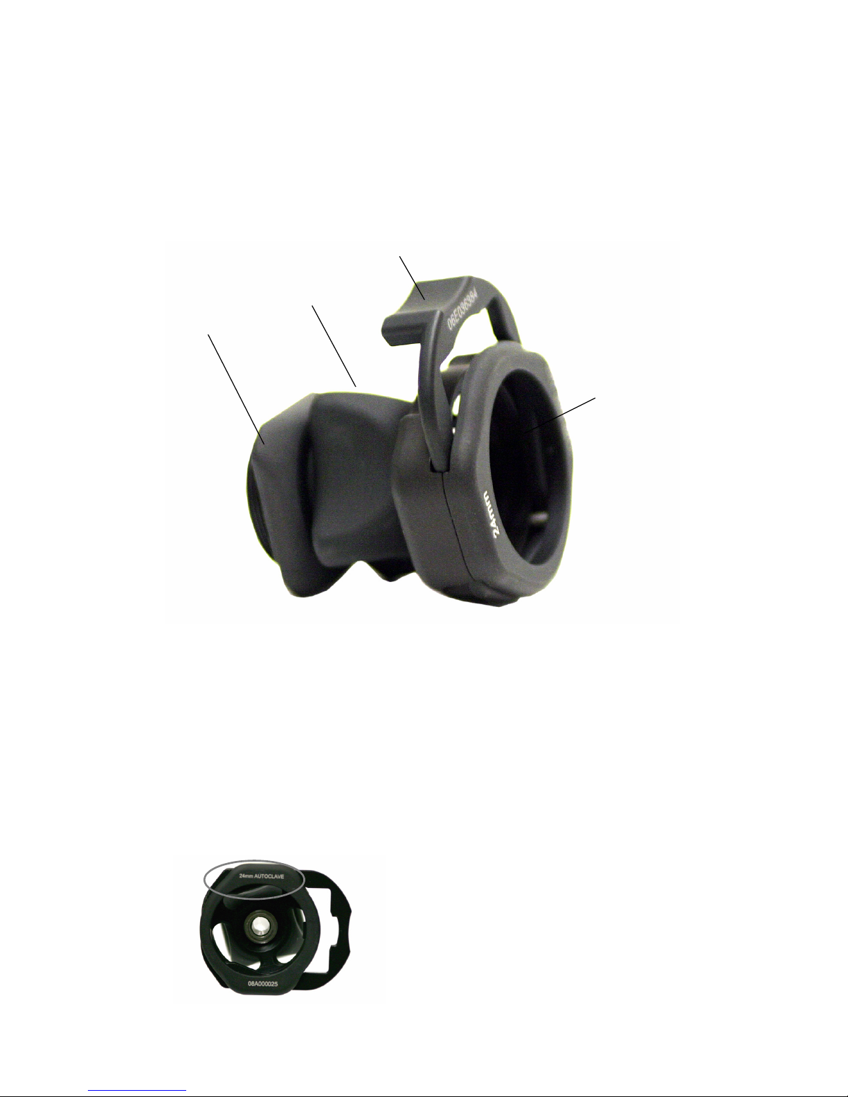
Figure 3: C-Mount coupler
1. Rear Adapter: Threads onto the camera head
2. Focusing Ring: Adjusts the coupler focus
3. Endobody Clamp: Secures the scope to the coupler
4. Scope End: Receives the endoscope
C-mount Couplers are available in autoclavable and non-autoclavable models:
Autoclavable
1188-410-110
(marked
AUTOCLAVE)
Non-autoclavable
1188-020-122
1
2
3
4
Page 16

EN-12
Setup and Interconnection
Note Stryker Endoscopy considers instructional training, or inservice,
an integral part of the 1188HD Medical Video Camera. Your local
Stryker Endoscopy sales representative will perform at least one
inservice at your convenience to help set up your equipment and
instruct you and your staff on its operation and maintenance. To
schedule an inservice, contact your local Stryker Endoscopy
representative after your equipment has arrived.
Setting Up the 1188HD Camera involves three steps:
1. Setting up the console
2. Setting up the camera head
3. Setting up the coupler
Setting Up the Console
Caution Equipment which employs RF communications may affect the
normal function of the 1188HD Camera. When choosing a
location for the 1188HD Camera, consult the
“Electromagnetic Compatibility” section of this manual to
ensure proper function.
To set up the console, make the following connections:
1. Connect AC power.
• Connect the AC power cord to the AC inlet on the rear console panel.
• Connect the other end to a hospital-grade outlet.
Warning Always connect the camera to an appropriate power source,
using a hospital-grade power cord. Loss of AC power will cause
the camera to shut down and the surgical image to be lost.
Caution Always set up the console in a location that allows adequate
ventilation (airflow) to the console. Insufficient ventilation
may cause the console to overheat and shut down.
Warning Only connect items to the camera that have been specified for
use with the camera. Connecting incompatible equipment may
cause unexpected results.
To avoid risk of electric shock, this equipment must only be
connected to a supply mains with protective earth.
Page 17
EN-13
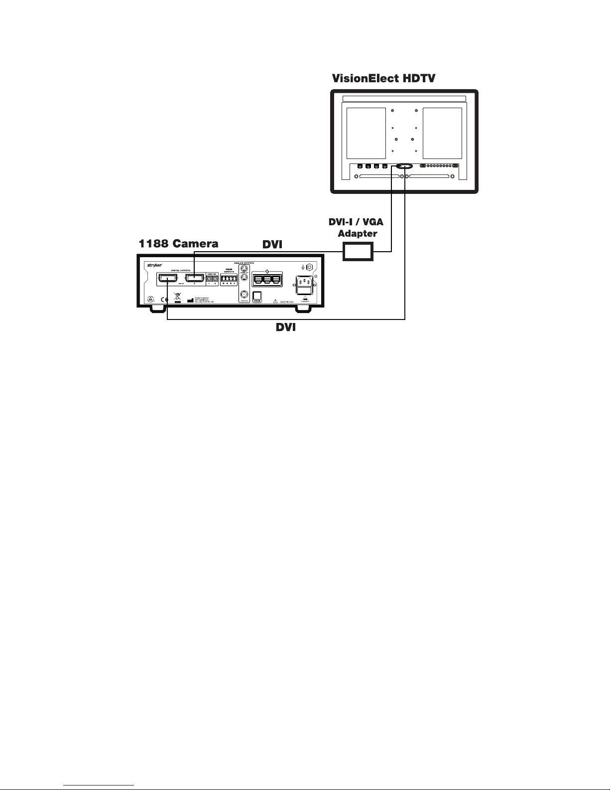
2. Connect the video output.
• The rear panel provides three analog and three digital-video outputs,
which can be used together or independently:
• Use the cables and outputs described above to connect the 1188HD to
other operating-room equipment. Wiring Diagrams 1-3 on the
following pages describe typical set-ups.
• If desired, connect any remote outputs using the remote cables
supplied with the 1188HD Camera. (See Wiring Diagram 2.) Devices
connected to the remote outputs of the 1188HD Camera can be
operated using the P buttons on the camera head and/or console. See
the “Operation Instructions” section of this manual for details.
• If desired, connect the SIDNE® interface as well. (See Wiring
Diagram 2.)
Warning When the 1188HD Camera is used with other equipment,
leakage currents may be additive. Ensure that all systems are
installed according to the requirements of IEC 60601-1-1.
Warning Do not touch the internal pin of the VIDEO-OUT BNC jack
and the patient simultaneously.
Output
Typ e
Output Cable Connector
Analog Composite Composite BNC
(push-and-turn connectors)
*S-VHS 1 S-VHS 4 pin Mini-Din
(push-only connectors)
*S-VHS 2 S-VHS 4 pin Mini-Din
(push-only connectors)
Digital **DVI-I 1 DVI 29-pin (push-only connectors, with two
tightening knobs)
**DVI-I 2 DVI 29-pin (push-only connectors, with two
tightening knobs)
DVI over optical
FIBER
Fiber (×4) Lucent connector fiber (×4) (push-only)
**On some monitors, S-VHS inputs may be labeled Y/C.
**The DVI connectors can also output analog SXGA signals through a DVI-I to VGA adapter.
Page 18
EN-14
Wiring Diagram 1: Camera and Flat-Panel Monitor
Page 19
EN-15
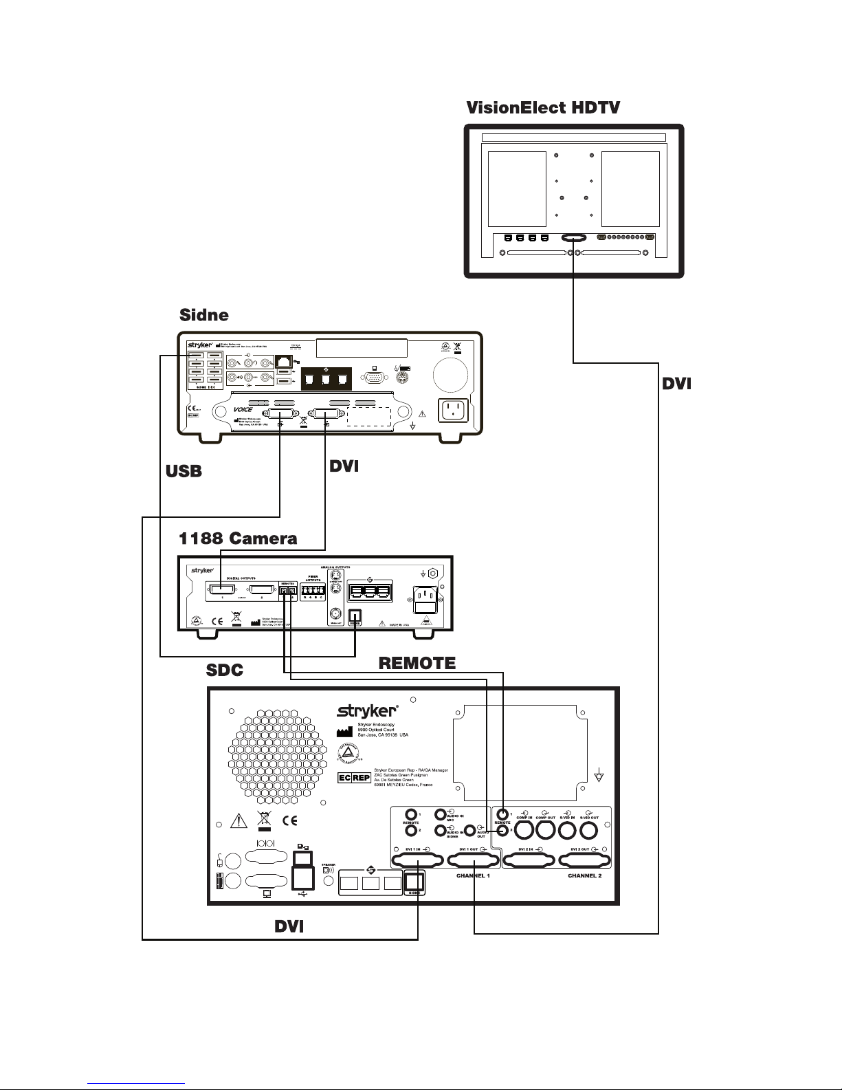
Wiring Diagram 2: Camera, SDC, SIDNE
®
, and Flat-Panel Monitor
Stryker European Rep. RA/QA Manager
ZAC Satolas Green Pusignan
Av. De Satolas Green
69881 MEYZIEU Cedex, France
Page 20
EN-16
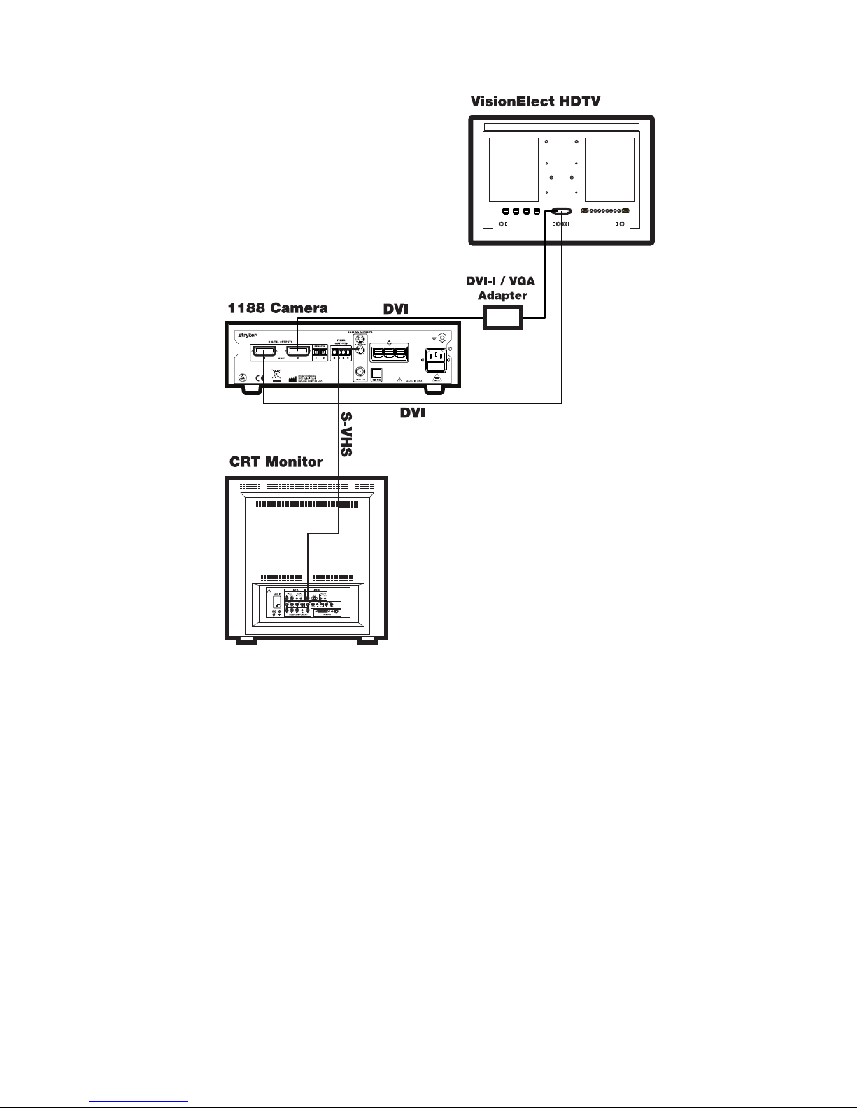
Wiring Diagram 3: Camera, Flat-Panel Monitor and CRT Monitor
Note If you are using any device with unterminated analog video
inputs, you must connect a cable from the VIDEO OUT of that
device to the VIDEO IN on the monitor.
Note An additional monitor may be connected using an open camera
output.
Note The camera console is shipped from the factory in NTSC video
format. If necessary, the video format can be changed to PAL by
using the “Options” submenu in the configuration menu. See the
“Using the Configuration Menu” section of this manual.
1. Power on the monitor.
2. Power on the camera.
Note A color bar pattern will appear on the monitor when the camera
head is not connected to the camera console. Follow the
instructions in the “Setting Up the Camera Head” section of this
manual to connect the camera head to the console.
Page 21
EN-17
Setting Up the Camera Head
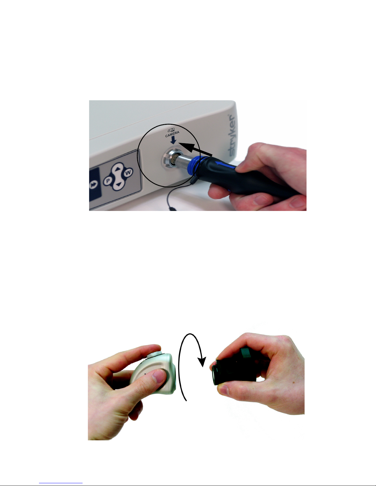
1. Connect the camera head to the console.
• Unscrew the soaking cap from the cable connector if necessary.
• Align the blue arrow on the cable connector with the blue arrow on
the camera-connector port on the front console panel (see Figure 4).
• Push in the connector until it locks in place.
Figure 4: Connecting the camera head to the console
Note To unplug the camera from the control unit, grasp the knobbed
portion of the connector and pull straight out.
Caution Do not severely bend the camera cable or damage may result.
Setting Up the Coupler
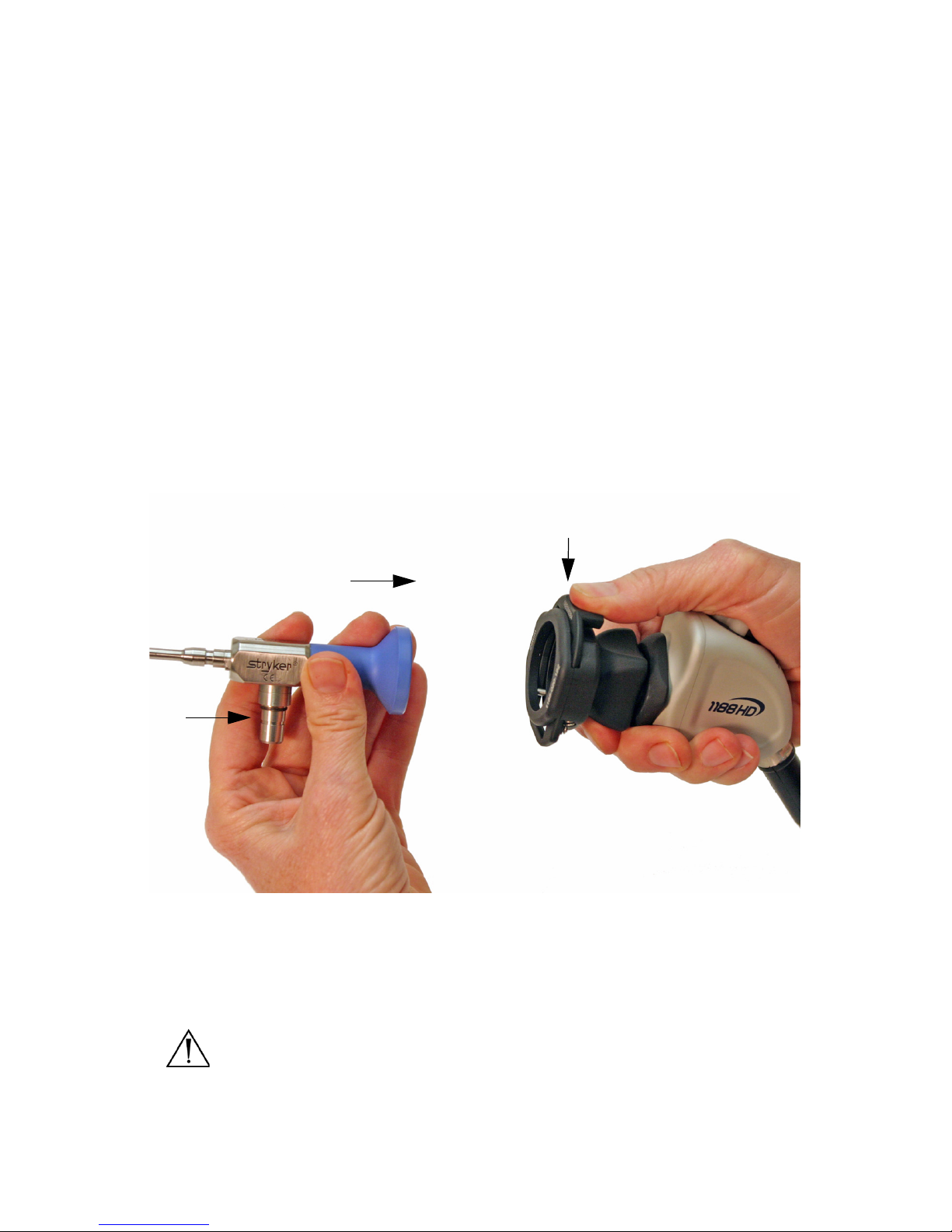
1. Attach the coupler to the camera head.
• Grasping the rear adapter, screw the coupler onto the camera head
(clockwise) until it forms a tight seal (see Figure 5).
Figure 5: Attaching a coupler to the camera head
Page 22
EN-18
Caution When attaching or removing the coupler, grip only the rear
adapter, as twisting other parts of the coupler may result in
mechanical damage.
Caution Do not overtighten the coupler, as this may damage the front
window of the camera.
Note For direct-coupled C-mount scopes (scopes that require no
coupler), thread the endoscope directly into the camera head
until it forms a tight seal.
Caution Do not overtighten a direct-coupled C-mount scope, as this
may damage the front window of the camera.
2. Attach an endoscope to the coupler.
• Remove the red dust cap if it is present.
• Push down on the endobody clamp (a) and insert the scope into the
scope end of the coupler (b). (See Figure 6.)
• Release the endobody clamp.
Figure 6: Attaching an endoscope to the camera head via the coupler
3. Attach a light cable from the light source to the light post on the
endoscope (c) as seen in Figure 6.
Warning Before each use, check the outer surface of the endoscope to
ensure there are no rough surfaces, sharp edges, or
protrusions.
(a)
(b)
(c)
Page 23
EN-19
Operation Instructions
Note Before operating the 1188HD Camera, ensure all components
have been set up according to the instructions in the “Setup and
Interconnection” section of this manual.
Warning Before using the 1188HD Camera in a surgical procedure, test
all components to ensure proper function. Ensure that a video
image appears on all video monitors before beginning any
procedure.
Powering the Camera On/Off
Press the power switch on the console to power the camera on or off.
Using the Camera Buttons
The camera console and camera head both feature a cross-shaped, four-button
keypad for controlling the 1188 camera (see Figure 7). These buttons are labeled
P, W, Up, an d D ow n.
Figure 7: The four-button keypad
P (Picture) Button
The P button controls up to two remote video accessories.
• Press the P button for less than one second to select Remote 1. One
beep will sound.
• Press the P button for more than one second to select Remote 2. Two
beeps will sound.
Page 24

EN-20
W (White Balance) Button
The W button activates the white-balance function or the light/zoom function.
The white balance function is used to correct slight color differences that exist
between different light sources or endoscopes.
• Press the W button for more than one second to activate the white-
balance function.
• Press the W button for less than one second to increase the light or
zoom level. The camera console can be set to “light” mode or “zoom”
mode using the Options submenu of the Configuration Menu. In
“zoom” mode, each W button press will raise the light level in four
steps. In “light” mode, each press will raise the zoom level in four
steps. When either mode has reached its maximum, pressing the W
button again will cycle the level back to the lowest setting.
Perform the white balance procedure before every surgical procedure.
Note Ensure that a scope and light source are attached to the camera,
and that the camera, light source and monitor are powered on
before adjusting the white balance.
1. Point the scope at several stacked 4 × 4 white gauze pads, a white
laparoscopic sponge, or any clean white surface.
2. Look at the monitor and make sure that no glare is visible off of the
white surface.
3. Press and hold the W button until “WHITE BALANCE” begins flashing
on the video monitor.
4. Continue pointing the scope at the white surface until the video monitor
indicates that white balance is “complete.” The video picture may change
color. If you cannot achieve an acceptable white balance, refer to the
“Troubleshooting” section of this manual.
Up and Down Buttons
The up and down buttons work together to increase or decrease the light/zoom
level.
The camera console can be set to “light” mode or “zoom” mode using the Options
submenu of the Configuration Menu. In “light” mode, pressing the arrow buttons
will raise or lower the automatic-shutter light-level setting in 29 steps. In “zoom”
mode, pressing the arrow buttons will raise or lower the zoom level in 8 steps.
Press the arrow button once to adjust the light level by one step or hold down the
button for a quicker transition.
Page 25

EN-21
Enhancement Buttons
The enhancement buttons increase or decrease picture sharpness. There are 16
levels of enhancement. The current enhancement level will be displayed briefly on
the monitor.
Surgical Specialty Button
The Surgical Specialty button selects one of nine pre-established camera settings.
Each camera setting optimizes camera performance for a specific surgical
application. The nine settings are:
•Arthroscopy
•Cystoscopy
•ENT
•Flexi-Scope
•Hysteroscopy
•Laparoscopy
•Laser
•Microscope
•Standard
The front panel LCD will display the current specialty.
Selecting the Display Language
The 1188HD has the capability of displaying text in the following languages:
To select a particular language, perform the following steps:
1. Hold down the Light/Zoom Up and Down buttons on the console until
the current language identifier appears.
2. Use the Enhance Up button to scroll through the available languages.
3. Hold down the Light/Zoom Up and Down buttons to lock in the
selected language. The LCD screen will then revert to the current
specialty setting.
Danish German Polish
Dutch Greek Portuguese
English Italian Simplified Chinese
Finnish Japanese Spanish
French Korean Swedish
Page 26

EN-22
Using the Configuration Menu
The Configuration Menu allows adjustment of some camera settings. Settings can
affect video quality, and care should be taken when altering them.
1. Enter the Configuration Menu by pressing the Enhance Up and Enhance
Down buttons on the console simultaneously for more than three
seconds. The menu will appear on the On-Screen Display (OSD).
2. Use the Enhance Up and Enhance Down buttons to scroll through the
menus and submenus:
•Shutter
•Color
•Options
3. Press the Specialty button to select an item from the Configuration
menu.
4. Use the Up and Down buttons to adjust the selection.
5. Press the P button to return to the Configuration Menu.
6. Press the P button again to exit the Configuration Menu.
Controlling Remote Video Accessories
The 1188HD Camera can remotely control up to two video accessories (such as
the SDC Ultra, a VCR, or a photo printer), enabling the user to capture images or
start and stop video recording by pressing the P button. (See also the “Using the
Camera Buttons” section of this manual.)
1. Connect the video accessory to one of the remote outputs on the rear
console panel. Use the provided remote cables. (See Wiring Diagram 2 in
the “Setting Up the Console” section of this manual.)
2. Press the P button for less than one second to select Remote 1. One beep
will sound.
3. Press the P button for more than one second to select Remote 2. Two
beeps will sound.
Page 27

EN-23
Using the SFB Serial Interface
The SFB serial connection on the console rear panel enables FireWire connection
to the Stryker Endoscopy Software Management Site (SMS). Connecting to this
site enables remote diagnostics and software updates.
Note This system feature is not necessary for regular camera system
operation.
Note This system feature requires an additional device (that is, a
computer) to connect to SMS.
Using the DVI Fiber Outputs
The 1188HD Camera contains four laser diodes to transmit a DVI output over
fiberoptic cables.
1. Connect four individual fibers (terminated in Lucent connectors) to the
red (R), green (G), blue (B) and clock (C) laser diodes on the console
rear panel.
2. Connect the four fibers to a compatible fiberoptic DVI receiver.
• The four fibers should be connected to the camera console in the
labeled order: RGBC
• The fibers should be connected to the monitor in one of two
configurations: CBGR (reverse order) or BGRC (R/B switched).
3. Ensure the fiberoptic output is enabled (on) via the Options Submenu in
the Configuration Menu. (See the section “Using the Configuration
Menu”.)
Note The 1188HD Camera is a Class 1 laser product per IEC 60825-1
and 21CFR.
Warning Using controls or adjustments or performing procedures
differently than specified in this manual may result in
hazardous radiation exposure.
Page 28

EN-24
Operating the Camera with a Light Source
Warning IMPORTANT SAFETY NOTICE: Before operating this device,
please read this operating manual thoroughly and carefully.
When using this device with a light source, fire and/or severe
injury may result to the patient, user or inanimate objects, if
the instructions in this manual are not followed. All light
sources can generate significant amounts of heat (41°C / 106°F)
at the scope tip, the scope light post, the light cable tip, and/or
near the light cable adapter. Higher levels of brightness from
the light source result in higher levels of heat. Always adjust
the brightness level of the camera and the monitor before
adjusting the brightness level of the light source. Adjust the
brightness level of the light source to the minimum brightness
necessary to adequately illuminate the surgical site. In
addition, adjust the internal shutter of the camera higher in
order to run the light source at a lower intensity. Avoid
touching the scope tip or the light cable tip to the patient, and
never place them on top of the patient, as doing so may result
in burns to the patient or user. In addition, never place the
scope tip, the scope light post, the light cable adapter, or the
light cable tip on the surgical drapes or other flammable
material, as doing so may result in fire. Always place the light
source in standby mode whenever the scope is removed from
the light cable or the device is unattended. The scope tip, scope
light post, light cable adapter, and light cable tip will take
several minutes to cool off after being placed in standby mode,
and therefore may still result in fire or burns to the patient,
user, or inanimate objects.
Page 29

EN-25
Troubleshooting
Problem Possible Solution
“System Error”
message
(Color bar
background)
• Camera head temporarily shut down due to
overcurrent.
• Turn off the console, wait 3 seconds, and turn it back
on.
• After sterilization, ensure the camera head has cooled
down before connecting it to the console.
“System Error”
message (Light blue
background)
• No video detected.
• After sterilization, ensure the camera head has cooled
down before connecting it to the console.
• Return the system for repair.
No color bar • Ensure the video-out from the console is connected to
the video-in on the monitor.
• Ensure all video systems are powered on.
• Ensure that the camera head is not connected to the
console.
• Turn off the console, wait 3 seconds, and turn it back
on.
No color bar
(Optical DVI only)
• Same as above.
• See the “Using the DVI Fiber Outputs” section of this
manual.
Incorrect picture
color
• Perform the white balance procedure. (See the “W
Button” section of this manual.)
• Check the color settings on the monitor.
White balance (WB)
quality not good
• See the solution for “Picture is too dark.”
• See the solution for “Picture is too bright.”
• Perform the white-balance procedure with the light
source connected to the scope. Use metal-halide or
xenon lighting (no fluorescent lighting).
Picture is too dark • Increase the camera light level with the camera head.
• Increase the light-source output.
• Check the fiber-optic light cable for excessive broken
fibers.
Page 30

EN-26
Picture is too bright • Decrease the camera light level.
• Decrease the light-source output.
• Ensure that Shutter submenu in the Configuration
menu has the following settings:
AGC Auto
Shutter On
Noise or snow on
picture when using
electrocautery
probes
• Plug the electrocautery generator into a separate
electrical outlet and separate the 1188HD power cord
from the electrocautery power cord.
• Separate the camera cable from the electrocautery
cable.
• Reposition the electrocautery grounding pad on the
patient.
Noise or snow on
picture when not
using electrocautery
probes
• Reduce Enhancement.
• Check for and replace faulty video cables.
No video picture
when the camera
head is plugged in
• Check to ensure that all devices in the video system are
plugged in and powered on.
• Check the connector on the camera-head cable for
broken pins.
• Detach the camera head from console and reconnect
or
• Turn off the console, wait 3 seconds, and turn it back
on.
Image is not well
centered
• Release the scope from the coupler and then reconnect
it. Make sure the scope is seated correctly in the
coupler.
Variability in color
reproduction
between different
light sources or
peripherals
• Perform the white-balance procedure. (See the “W
Button” section of this manual.)
• Check the settings on video peripherals.
• Ensure the light source has a proper infrared filter
(check with manufacturer specifications).
Foggy picture (loss
of definition and
clarity)
• Refocus the camera.
• Refocus the coupler.
• Clean and dry both the scope and the coupler windows.
• Remove the coupler from the camera head and remove
any moisture that has built up between the two
components.
Problem Possible Solution
Page 31

EN-27
Note If this troubleshooting guide does not resolve the problem, call
Stryker Technical Support at 1-877-478-7953 (inside the U.S.) or
refer to the “Service and Claims” section of this manual.
Optics are dirty • Rotate the scope. If dust particles in the picture rotate,
the dust is located on the scope itself. Follow the
manufacturer’s instructions for cleaning the eyepiece
and negative lens.
• If particles in the picture do not move when you rotate
the scope, the particles are located on the coupler or
camera. Remove the scope and clean the window on
the front of the coupler with a dry or alcohol-tipped
cotton swab.
• If dust particles lie between the coupler and camera,
remove the coupler and clean the coupler and camera
windows.
• Ensure all components are completely dry before
reassembling them, or fogging may result.
Blurry picture • Ensure the coupler or C-Mount scope is in focus.
• Increase the enhancement.
• Ensure the specialty switch is not set to FLEXI-SCOPE
unless you are using a flexible scope.
Problem Possible Solution
Page 32

EN-28
Cleaning and Sterilization
The camera console is not intended to come into contact with the patient. It may
be cleaned, but not sterilized. The camera head and coupler may contact the
patient and must both be cleaned and sterilized prior to every use.
Cleaning the Camera Console
Warning Disconnect the console from the AC power source before
cleaning.
Should the camera console need cleaning, wipe it down with a sterile cloth and
mild cleaning solution.
Caution Never immerse or sterilize the camera console as this will
damage the camera and void the warranty.
Reprocessing the Camera Head
These reprocessing instructions are provided in accordance with ISO 17664.
While they have been validated by the manufacturer of the medical device as
being capable of preparing the device for re-use, it remains the responsibility of
the processor to ensure that the reprocessing as actually performed, using
equipment, materials, and personnel in the reprocessing facility, achieves the
desired result. This normally requires validation and routine monitoring of the
process.
Warnings
• This device must be cleaned and sterilized prior to the first use and after
every subsequent use.
• Do not sterilize the autoclavable camera head (1188-410-105) with Steris/
Amsco V-Pro or Steris System 1E. Steam sterilization is recommended.
• Use only the sterilization cycles outlined in this document. Using
unspecified sterilization cycles may damage the device or result in
incomplete sterilization.
• Separate the camera head, coupler, and scope prior to cleaning, disinfection,
or sterilization. If the coupler and camera head are cleaned, disinfected, or
sterilized as a single unit, disconnecting the coupler during use will
compromise the sterility of the two products. (Refer to the coupler and scope
product manuals for reprocessing instructions.)
• Wear appropriate protective equipment: gloves, eye protection, etc.
Page 33

EN-29
Cautions
• Always install the soaking cap prior to processing the camera.
Failure to properly tighten the soaking cap will corrode the
connector pins and void the warranty.
• Inspect the camera cable for cuts and breaks before soaking in any
fluid. Return any damaged camera to Stryker for service.
• Never soak the camera in the same tray with sharp instruments.
• Do not use brushes or pads with metal or abrasive tips during
manual cleaning, as permanent scoring or damage could result.
• To minimize galvanic corrosion, avoid soaking dissimilar metals in
close proximity.
• Only camera heads marked
AUTOCLAVE can withstand steam
sterilization. Autoclaving camera heads that do not bear this
marking will result in product damage.
• Allow the device to air cool following steam sterilization. Rapid
cooling or “quenching” in a liquid will damage the device and void
the warranty.
• Allow the camera head to cool before connecting it to the console.
Connecting the camera head while it is still hot may result in
system error.
Limitations on Reprocessing
• Do not cross-sterilize the device. Using multiple sterilization
methods may significantly reduce the performance of the device.
• Do not leave the device in solutions longer than necessary. This
may accelerate normal product aging.
• Proper processing has a minimal effect on this device. End of life is
normally determined by wear and damage due to use.
• Damage incurred by improper processing will not be covered by the
warranty.
Page 34

EN-30
Instructions
Point of Use
• Wipe excess soil from the device using disposable paper towels.
• If an automated reprocessing method will be used, rinse any
channels in the device with 50mL of sterile distilled water
immediately after use.
Containment and Transportation
• Reprocess the device as soon as reasonably practical following use.
• Transport the device in a tray to avoid damage.
Preparation for Cleaning
1. Disassemble the coupler from the scope and camera head.
2. Prepare an enzymatic detergent according to the manufacturer’s
recommendations (one ounce per gallon of tap water at 35 - 40°C).
3. Wipe the entire device with the detergent, using a clean cloth.
4. Immerse the device in the detergent. Inject any inside regions of the
device with 50mL of the detergent solution to remove loose debris.
5. Soak the device in the detergent for at least 15 minutes.
Page 35

EN-31
Cleaning: Manual
1. Brush
• Thoroughly brush the exterior of the device with a soft-bristled brush,
focusing on any mated or rough surfaces.
• Inject any lumen or mated surface a minimum of five times with at least
50mL of the detergent.
• Brush any lumens a minimum of five times from each end, using an
appropriate bottle brush.
• Brush any movable parts in their extreme open and closed positions.
2. Rinse
• Rinse the device with treated water at ambient temperature to remove all
detergent residue. Flush any lumens or mated surfaces a minimum of 5
times. Once all detergent residues have been removed, continue to rinse
for a minimum of 30 seconds.
• Drain excess water from the device and dry it using a clean cloth or
pressurized air.
• Visually inspect the device for cleanliness, paying close attention to hardto-reach areas. If visible soil remains, repeat steps 1 and 2.
3. Soak
• Prepare a non-enzymatic detergent, according to the manufacturer’s
recommendations of 0.25 ounces/gallon tap water at 35 - 40°C.
• Fully immerse the device and inject any lumens and mated surfaces with
at least 50mL of the detergent.
• Soak the device for a minimum of 15 minutes.
4. Brush
• Thoroughly brush the exterior of the device using a soft-bristled brush.
• Inject the prepared detergent into any cannulae, lumens, or mated
surfaces a minimum of 5 times.
• Brush any lumens a minimum of 5 times from each end, using an
appropriate bottle brush.
• Actuate the device, brushing around any movable parts in all extreme
positions.
5. Rinse
• Thoroughly rinse the device with treated water until all detergent residue
is removed. Flush any lumens or crevices 5 times. After the detergent
residue is removed, continue rinsing for a minimum of 30 seconds.
• Drain the excess water from the device and dry it with a clean cloth or
pressurized air.
Page 36

EN-32
Cleaning: Automated
1. Brush
• Brush both ends of any lumens a minimum of five times, using an
appropriate bottle brush.
2. Rinse
• Rinse the device with treated water at ambient temperature until
there is no visible detergent residue. Continue to rinse for a
minimum of 30 seconds after all detergent residue has been
removed.
• Place the device in the washer on an incline to facilitate drainage.
3. Automated wash
• Program the washer using the following parameters:
Disinfection (optional)
1. Disinfect the device by submerging it in a disinfection agent. Follow
the disinfection agent manufacturer’s recommended concentrations,
temperatures, and exposure times.
2. Thoroughly rinse and flush all parts and lumens with running,
demineralized water to remove the disinfectant.
3. Dry all parts with a lint-free towel immediately after rinsing.
* If necessary, use pressurized air to aid in drying. Visually inspect each
device for cleanliness.
Phase Recirculation
Time
Wa te r
Te m pe r at u re
Detergent Type
and Concentration
(If applicable)
Pre Wash 2 minutes Cold N/A
Enzyme
Wa sh
2 minutes Hot Enzymatic
Detergent
Wash 1 2 minutes Set Point
(66° C)
Regular Detergent
Rinse 1 2 minutes Hot N/A
Dry Phase 7 minutes 115° C N/A
Page 37

EN-33
Drying
• For automated drying, use the drying cycle provided with the
washer/disinfector.
• For manual drying, use a lint-free cloth.
• Dry any lumens with compressed air.
Maintenance, Inspection, and Testing
• Inspect the device on a continual basis. If a problem is observed or
suspected, the device should be returned for repair.
• Inspect all components for cleanliness. If fluid or tissue buildup is
present, repeat the above cleaning and disinfection procedures.
• Inspect the camera cable for cuts and breaks. Return any damaged
camera to Stryker for service.
Packaging
N/A
Sterilization
After performing the cleaning instructions specified above, perform one of the
following sterilization cycles.
Page 38

EN-34
Steam
• Steam sterilization is intended only for camera heads and couplers
marked
AUTOCLAVE.
• Rapid cooling, or “quenching,” the coupler after autoclaving will
result in product damage.
• The water used in the autoclave process must meet standards for
clean steam per AAMI ST 79 Appendix M – Steam Quality
requirements.
Ethylene Oxide (EO)
Note for United States users: For all autoclave-compatible devices, Stryker
recommends using steam sterilization instead of liquid chemical sterilization.
Sterilizer Type “Flash”
Gravity
“Flash”
Prevacuum
Gravity Prevacuum
Minimum
Te m p er a t u re
132 - 137°C
(270 - 279°F)
132 - 137°C
(270 - 279°F)
132 - 137°C
(270 - 279°F)
132 - 137°C
(270 - 279°F)
Minimum
Cycle Time
10 minutes 3 minutes 10 minutes 3 minutes
Product
Configuration
Unwrapped Unwrapped Double
wrapped
Double
wrapped
Drying Time — — 60 minutes 60 minutes
Preconditioning parameters
Temperature 55 ± 2°C (131 ± 4°F)
Exposure
Concentration (100% EO) 725 mg/L
Temperature 131 °F (55°C) ± 5 °F
Time 1 hour
Chamber Humidity 70% RH (50-80 %) ± 5%
Aeration parameters
Aeration Time 12 hours
Temperature 35 – 55°C (95° - 131°F)
Page 39

EN-35
Steris System 1 / System 1E
1. Clean and prepare the camera head and cable as recommended in this
user guide. Ensure the soaking cap is installed.
2. Sterilize the camera head and cable using Steris® System 1™ with
Steris® 20 Sterilant, or System 1E™ with S40™ Sterilant. Follow the
manufacturer's instructions.
3. Allow the camera head, cable, coupler, and scope to completely dry
before reassembly. Any moisture on the threads will cause the camera
and coupler windows to fog during use.
Steris/Amsco V-PRO 1
1. Clean and prepare the camera head and cable as recommended in this
user guide. Ensure the soaking cap is installed.
2. If using a sterilization tray (optional), follow any additional
instructions provided with the tray. Use only trays that are approved
for sterilization with Steris/Amsco® V-PRO™ 1.
3. Double-wrap the camera head and cable (or tray, if being used) prior
to sterilization.
4. Sterilize the camera head and cable using the V-PRO™ 1 Plus Sterilizer
(Non-Lumen or Standard cycle) or the V-PRO™ 1 Sterilizer (Standard
cycle).
5. Allow the camera head, cable, coupler, and scope to completely dry
before reassembly. Any moisture on the threads will cause the camera
and coupler windows to fog during use.
Sterrad
1. Clean and prepare the camera head and cable as recommended in this
user guide. Ensure the soaking cap is installed.
2. Sterilize the camera head and cable using the Sterrad™ NX or 100s
Sterilization System.
3. Allow the camera head, cable, coupler, and scope to completely dry
before reassembly. Any moisture on the threads will cause the camera
and coupler windows to fog during use.
Note: Steris® System 1™ is not intended for use in the United States.
Do not sterilize the autoclavable camera head (1188-410-105) with Steris System 1E.
Do not sterilize the autoclavable camera head (1188-410-105) with V-PRO 1. Steam
sterilization is recommended.
Page 40

EN-36
Using Sterile Drapes
Using sterile drapes will ensure maximum longevity of your 1188HD Camera
Head. For best results, follow the instructions provided by the drape
manufacturer.
User Maintenance
Replacing the Fuses
1. Unplug the power cord from the wall outlet and remove the cord from
the camera console.
2. Unlatch the fuse holder above the AC inlet and remove it. (You may
need to press the tab on the fuse holder with a slender screwdriver to
release the latch.)
3. Replace the fuse with the same value and rating.
Warning To avoid the risk of fire, use only fuses of the value specified on
the fuse label located on the rear panel of the camera console.
4. Reinstall the fuse holder until the tab snaps in place.
Periodic Maintenance Schedule
Warning To ensure safe operation of the Model 1188HD Medical Video
Camera you should periodically perform the following
procedure:
Every 12 months, check the earth leakage current to <500µA (<300µA in U.S.A.),
ground protective earth impedance to <0.1 ohms, and power consumption less
than or equal to rated power. Use a true RMS digital multimeter and safety
analyzer to perform this test.
Note Refer calibration and operating difficulties not detailed in this
manual to your Stryker Endoscopy sales representative.
Disposing of the 1188HD
The 1188HD must be disposed of according to local laws and hospital practices.
Storage
N/A
Page 41

EN-37
This product is considered electronic equipment and must not be disposed of as
unsorted municipal waste and must be collected separately. Please contact the
manufacturer or other authorized disposal company to decommission your
equipment.
Technical Specifications
60Hz settings are displayed first. (50Hz settings follow in parentheses.)
Imaging System
1/3" Progressive Scan CCDs
High Definition
Scanning System
Horizontal: 64.00 kHz (60.00 kHz)
Vertical: 60.02 Hz (50.00 Hz)
Video Outputs
Digital/Analog: Two Digital Video Interface (DVI)/RGBHV
1280 × 1024 (HD), 720p (HDTV) format
Connector: 29-pin DVI-I
Composite: One NTSC standard (PAL standard)
Connector: BNC coaxial
Y/C: Two S-VHS
Connector: 4-pin mini-DIN
Digital Fiber: HD, HDTV (R, G, B, Clk)
Connector: Four Lucent fiber connectors with 1.25 mm
ferrules
Mounting
Endoscope eyepiece used with C-mount coupler
C-mount camera head used with C-mount scopes
(C-mount coupler/scope thread: 1"-32UN-2A)
Auto Shutter Range
1/60 (1/50) – 1/50,000 second
Operating Conditions
Temperature: 10 – 30°C
Relative Humidity: 30 – 75%
Transport and Storage Conditions
Temperature: -20 – 60°C
Relative Humidity: 10 – 75%
Atmospheric Pressure: 700 – 1060 hPa
Page 42

EN-38
Input Electrical Ratings
100 – 240VAC ± 10% (0.6A) @ 47 – 63Hz
Total Shipping Weight
13 lbs. (6.0 kg) Camera console
0.5 lbs. (0.226 kg) Coupler
1.5 lbs. (0.680 kg) Camera head
Dimensions
Camera Console: 12.5" w × 3.3" h × 15.25" d
(31.8 cm w × 8.4 cm h × 38.7 cm d)
Camera Head Cable to Camera Console:
10.3 ft (3.15 m) sealed cable
20.7 ft (6.30 m) cable extension available
Enhancement
16 levels (switchable)
Classification
Class I Equipment
Type BF Applied Part
Water Ingress Protection, IPX0—Ordinary Equipment
Continuous Operation
Complies with Laser Product Standards
Class 1 Laser Product
Contains four 850-nm laser diodes
This product complies with IEC 60825-1:1993+A1:1997+A2:2001.
This product complies with 21CFR, Subchapter J, Parts 1040.10 and
1040.11, except for deviations pursuant to Laser Notice No. 50, dated
July 26, 2001.
Please contact your local Stryker Endoscopy sales representative for information
on changes and new products.
Page 43

EN-39
Electromagnetic Compatibility
Like other electrical medical equipment, the 1188HD Camera requires special
precautions to ensure electromagnetic compatibility with other electrical medical
devices. To ensure electromagnetic compatibility (EMC), the 1188HD Camera
must be installed and operated according to the EMC information provided in
this manual.
Note The 1188HD Camera has been designed and tested to comply
with IEC 60601-1-2 requirements for EMC with other devices.
Caution Equipment which employs RF communications may affect the
normal function of the 1188HD Camera.
Warning Do not use cables or accessories other than those provided
with the 1188HD Camera, as this may result in increased
electromagnetic emissions or decreased immunity to such
emissions.
Warning If the 1188HD Camera is used adjacent to or stacked with
other equipment, observe and verify normal operation of the
1188HD Camera in the configuration in which it will be used
prior to using it in a surgical procedure. Consult the tables
below for guidance in placing the 1188HD Camera.
Guidance and Manufacturer's Declaration: Electromagnetic Emissions
1188HD Camera is intended for use in the electromagnetic environment specified below. The
customer or the user of 1188HD Camera should ensure that it is used in such an environment.
Emissions test Compliance Electromagnetic Environment - guidance
RF emissions CISPR
11
Group 1
1188HD Camera uses RF energy only for its
internal function; therefore, its RF emissions are
very low and are not likely to cause any
interference in nearby electronic equipment.
RF emissions CISPR
11
Class A
The 1188HD Camera is suitable for use in all
establishments other than domestic
establishments and those directly connected to
the public low-voltage power supply network
that supplies buildings used for domestic
purposes, provided the following warning is
heeded:
Warning: This system is intended for use by
healthcare professionals only. This system may
cause radio interference or may disrupt the
operation of nearby equipment. It may be
necessary to take mitigation measures, such as
reorienting or relocating the system or shielding
the location.
Harmonic emissions
IEC61000-3-2
Class A
Voltage Fluctuations/
flicker emissions
IEC61000-3-3
Complies
Page 44

EN-40
Guidance and Manufacturer's Declaration: Electromagnetic Immunity
1188HD Camera is intended for use in the electromagnetic environment specified below.
The customer or the user of 1188HD Camera should ensure that it is used in such an environment.
Immunity Test
IEC 60601 Test
Level
Compliance Level
Electromagnetic
Environment:
Guidance
Electrostatic Discharge
(ESD)
IEC61000-4-2
±6kV contact
±8kV air
±2,4,6kV contact
±2,4,8kV air
Floors should be
wood, concrete, or
ceramic tile. If floors
are covered with
synthetic material,
the relative humidity
should be at least
30%.
Electrical fast transient/
burst
IEC61000-4-4
±2kV for power
supply lines
±1kV for input/
output lines
±2kV line to ground
±1kV line to line
Mains power quality
should be that of a
typical commercial
or hospital
environment.
Surge
IEC61000-4-5
±1kV differential
mode
±2kV common
mode
±0.5, 1kV
differential mode
±0.5, 1, 2kV
common mode
Mains power quality
should be that of a
typical commercial
or hospital
environment.
Voltage dips, short
interruptions and voltage
variations on power supply
input lines
IEC61000-4-11
<5% Ut (>95% dip
in Ut) for 0.5 cycle
40% Ut (60% dip in
Ut) for 5 cycles
70% Ut (30% dip in
Ut) for 25 cycles
<5% Ut (>95% dip
in Ut) for 5 sec.
<5% Ut (>95% dip
in Ut) for 0.5 cycle
40% Ut (60% dip in
Ut) for 5 cycles
70% Ut (30% dip in
Ut) for 25 cycles
<5% Ut (>95% dip
in Ut) for 5 sec.
Mains power quality
should be that of a
typical commercial
or hospital
environment. If the
user of 1188HD
Camera requires
continued operation
during power mains
interruptions, it is
recommended that
1188HD Camera be
powered from an
uninterruptible
power supply or a
battery.
Power frequency (50/60Hz)
magnetic field
IEC 61000-4-8
3 A/m N/A
Power-frequency
magnetic fields
should be at levels
characteristic of a
typical location in a
typical commercial
or hospital
environment.
NOTE: Ut is the AC mains voltage prior to application of the test level.
Page 45

EN-41
Guidance and Manufacturer's Declaration: Electromagnetic Immunity
1188HD Camera is intended for use in the electromagnetic environment specified below.
The customer or the user of 1188HD Camera should ensure that it is used in such an environment.
Immunity
Test
IEC 60601 Test
Level
Compliance
Level
Electromagnetic Environment:
Guidance
Conducted RF
IEC 61000-4-6
Radiated RF
IEC 61000-4-3
3 Vrms
150 kHz to 80 MHz
3 V/m
80MHz to 2.5 GHz
3 V
3 V/m
Portable and mobile RF communications
equipment should be used no closer to
any part of the 1188HD Camera system,
including its cables, than the
recommended separation distance
calculated from the equation applicable to
the frequency of the transmitter.
Recommended Separation Distance
80 MHz to 800 MHz
800 MHz to 2.5 GHz
where P is the maximum output power
rating of the transmitter in watts (W)
according to the transmitter manufacturer
and d is the recommended separation
distance in meters (m).
Field strengths from fixed RF transmitters,
as determined by an electromagnetic site
survey
(a)
, should be less than the
compliance level in each frequency
range
(b)
.
Interference may occur in the vicinity of
equipment marked with the following
symbol:
NOTE 1: At 80 MHz and 800 MHz, the higher frequency range applies.
NOTE 2: These guidelines may not apply in all situations. Electromagnetic propagation is affected by
absorption and reflection from structures, objects, and people.
d 1.17 P=
d 1.17 P=
d 2.33 P=
Page 46

EN-42
(a) Field strengths from fixed transmitters, such as base stations for radio (cellular/cordless)
telephones and land mobile radios, amateur radio, AM and FM radio broadcast, and TV broadcast,
cannot be predicted theoretically with accuracy. To assess the electromagnetic environment due to
fixed RF transmitters, an electromagnetic site survey should be considered. If the measured field
strength in the location in which the 1188HD Camera system is used exceeds the applicable RF
compliance level above, the 1188HD Camera system should be observed to verify normal operation. If
abnormal performance is observed, additional measures may be necessary, such as reorienting or
relocating the 1188HD Camera unit.
(b) Over the frequency range 150 kHz to 80 MHz, field strengths should be less than 3 V/m.
Recommended Separation Distances Between Portable and Mobile RF Communications
Equipment and the 1188HD Camera System
The 1188HD Camera system is intended for use in an electromagnetic environment in which radiated
RF disturbances are controlled. The user of the 1188HD Camera system can help prevent
electromagnetic interference by maintaining a minimum distance between portable and mobile RF
communications equipment (transmitters) and the 1188HD Camera system as recommended below,
according to the maximum output power of the communications equipment.
Rated maximum output
power (W) of transmitter
Separation distance (m) according to frequency of transmitter
150 kHz to 80 MHz 80 MHz to 800 MHz 800 MHz to 2.5 GHz
0.01 0.12 0.12 0.23
0.1 0.37 0.37 0.74
11.171.172.33
10 3.70 3.70 7.37
100 11.70 11.70 23.30
For transmitters rated at a maximum output power not listed above, the recommended separation
distance (d) in meters (m) can be estimated using the equation applicable to the frequency of the
transmitter, where P is the maximum output power rating of the transmitter in watts (W) according to
the transmitter manufacturer.
NOTE 1: At 80 MHz and 800 MHz, the separation distance for the higher frequency range applies.
NOTE 2: These guidelines may not apply in all situations. Electromagnetic propagation is affected by
absorption and reflection from structures, objects, and people.
Guidance and Manufacturer's Declaration: Electromagnetic Immunity
1188HD Camera is intended for use in the electromagnetic environment specified below.
The customer or the user of 1188HD Camera should ensure that it is used in such an environment.
d 1.17 P=
d 1.17 P=
d 2.33 P=
Page 47

EN-43
Warranty
Stryker Endoscopy warrants the 1188HD Medical Video Camera against defects
in both materials and workmanship to the registered owner at the time of
purchase. All components including the Charge Coupled Devices (CCDs) located
in the camera head are covered by the warranty for a period of one year from the
date of purchase.
This warranty does not apply to any unit which has been subject to misuse,
neglect, improper installation or that which has been altered, adjusted, or
tampered with by any person other than Stryker Endoscopy authorized
personnel.
If upon examination by authorized service personnel, it is determined that the
malfunction is due to misuse or abuse, warranty provisions will not apply. An
estimate of the cost of repair work will be given to the customer prior to servicing
and repairing the unit.
The customer is responsible for returning the defective equipment to the factory
at his or her own expense. Stryker Endoscopy or its representative will service the
unit, repair or replace any defective parts thereof, and return the unit.
If, upon examination, it is determined that the fault has been caused by misuse or
abnormal conditions of operation, the repairs will be billed to the customer as
out-of-warranty repairs.
Instruments repaired under Stryker Endoscopy’s standard repair program will be
issued a thirty-day warranty against defects in both materials and workmanship,
provided the original warranty period has passed. Instruments submitted due to
defects in materials and workmanship during the warranty period will be
repaired at no charge to the customer.
The warranty as set forth herein is exclusive and in lieu of all other warranties,
remedies, obligations and liabilities of Stryker Endoscopy Inc., expressed or
implied, including the implied warranties of merchantability and fitness for use
and of consequential damages. These products are being sold only for the purpose
described herein, and such warranty only runs to the purchaser. In no event shall
Stryker Endoscopy be liable for any breach of warranty in any amount exceeding
the purchase price of the product.
No agent, employee or representative of Stryker Endoscopy has the authority to
bind the Company to any other warranty, affirmation, or representation
concerning this instrument.
This warranty is valid only to the original purchaser of Stryker Endoscopy
products directly from Stryker Endoscopy or from a Stryker Endoscopy
authorized agent. The warranty cannot be transferred or assigned by the original
purchaser.
Page 48

EN-44
Service and Claims
Caution Never open the camera head or cable, or attempt any service
not described in this manual. These units have been factory
sealed to prevent moisture from entering the electronic
components. If the camera head or the cable seal is
intentionally broken, the equipment warranty will be void.
Furthermore, any repairs made to the camera system will
require evaluation to the requirements of applicable electrical
safety standards.
If service is needed either during or after the warranty period:
1. Contact Stryker Endoscopy at 1-800-624-4422 or phone your local
Stryker Endoscopy sales representative.
2. Package all the components carefully in the original shipping container
if possible.
3. Ship the camera, prepaid and insured to:
Stryker Endoscopy Customer Service
Attention: Repair Department
5900 Optical Court
San Jose, CA 95138
USA
© Stryker and Stryker Endoscopy are registered trademarks of
Stryker Corporation.
Page 49

FR-45
1188HD
Caméra vidéo
Guide de l’utilisateur
Contenu
Avertissements et précautions d’emploi ....... FR-47
Définition des symboles ............................................................ FR-50
Description et utilisation de l’appareil ........... FR-52
Indications/Contre-indications .................................................. FR-52
Console de la caméra ............................................................... FR-53
Tête de caméra ......................................................................... FR-55
Coupleur à monture en C ......................................................... FR-56
Installation et interconnexion ........................ FR-57
Installation de la console .......................................................... FR-57
Installation de la tête de caméra ............................................... FR-62
Installation du coupleur ............................................................. FR-63
Instructions d’utilisation ............................... FR-65
Mise sous/hors tension de la caméra ....................................... FR-65
Utilisation des boutons de la caméra ....................................... FR-65
Sélection de la langue d’affichage ............................................ FR-67
Utilisation du menu Configuration ............................................ FR-68
Contrôle des accessoires vidéo distants .................................. FR-68
Utilisation de l’interface série SFB ............................................ FR-69
Utilisation des sorties en fibre optique DVI ............................... FR-69
Utilisation de la caméra avec une source lumineuse ................ FR-70
Dépannage .................................................... FR-71
Nettoyage et stérilisation .............................. FR-74
Nettoyage de la console de la caméra ..................................... FR-74
Retraitement de la tête de caméra ........................................... FR-74
Maintenance par l’utilisateur ..................................................... FR-83
Page 50

FR-46
Spécifications techniques ............................. FR-84
Compatibilité électromagnétique .............................................. FR-85
Garantie ........................................................ FR-90
Service technique et réclamations ................ FR-91
Page 51

FR-47
Avertissements et précautions
d’emploi
Lire intégralement ce manuel et en suivre attentivement les instructions.
Les termes avertissement, précaution et remarque ont une signification
particulière et doivent être considérés avec attention :
Avertissement La sécurité personnelle du patient et du praticien peut être
mise en cause. Ne pas tenir compte de ces informations
pourrait causer des blessures au patient ou à l’utilisateur.
Attention Des précautions ou des procédures techniques spéciales
doivent être respectées afin d’éviter tout endommagement
de l’équipement.
Remarque Informations spéciales pour faciliter l’entretien ou clarifier des
informations importantes.
Un point d’exclamation dans un triangle est destiné à attirer
l’attention de l’utilisateur sur la présence d’instructions
d’utilisation et d’entretien importantes dans la documentation
accompagnant le produit.
Un éclair dans un triangle avertit l’utilisateur de la présence d’une
tension électrique dangereuse. Faire appel au personnel agréé
pour toute assistance technique.
AVIS DE SÉCURITÉ IMPORTANT :
lire attentivement ce manuel
d’utilisation avant d’actionner ce matériel. Lors de l’utilisation de ce matériel
avec une source lumineuse, le non-respect des instructions contenues dans ce
manuel peut entraîner un incendie et/ou des blessures graves pour le patient,
l’utilisateur ou des objets inanimés. Toutes les sources lumineuses peuvent
générer des volumes importants de chaleur à l’extrémité de l’endoscope,
au port d’éclairage de l’endoscope, à l’extrémité du câble d’éclairage et/ou
à proximité de l’adaptateur de câble d’éclairage. Des niveaux plus élevés de
luminosité de la source lumineuse génèrent des niveaux supérieurs de chaleur.
Toujours régler le niveau de luminosité de la caméra et du moniteur avant de
régler le niveau de luminosité de la source lumineuse. Régler le niveau de
luminosité de la source lumineuse sur la luminosité minimum nécessaire
à l’éclairage adéquat du site chirurgical. En outre, régler l’obturateur interne
de la caméra à un niveau plus élevé afin de faire fonctionner la source
lumineuse à une intensité inférieure. Éviter que l’extrémité de l’endoscope
ou du câble d’éclairage touche le patient et ne jamais les placer sur le patient,
cela pourrait entraîner des brûlures pour le patient ou l’utilisateur. De plus,
ne jamais placer l’extrémité de l’endoscope, le port d’éclairage de l’endoscope,
l’adaptateur du câble d’éclairage ou l’extrémité du câble d’éclairage sur les
Page 52

FR-48
champs opératoires ou tout autre matériau inflammable. En effet, cela
pourrait entraîner un incendie. Toujours placer la source lumineuse en mode
de veille lorsque l’endoscope est retiré du câble d’éclairage ou que le dispositif
est laissé sans surveillance. Une fois que la source est placée en mode de veille,
le refroidissement de l’extrémité de l’endoscope, du port d’éclairage de
l’endoscope, de l’adaptateur de câble d’éclairage et de l’extrémité du câble
d’éclairage prend plusieurs minutes. Ces parties pourraient dès lors toujours
entraîner un incendie ou des brûlures pour le patient, l’utilisateur ou des
objets inanimés.
Afin d’éviter tout risque de blessure grave du patient et de l’utilisateur et/ou
d’endommagement de l’appareil, l’utilisateur doit :
1. Déballer soigneusement l’appareil et vérifier qu’il n’a pas été endommagé
au cours de l’expédition. Le cas échéant, consulter le paragraphe
« Service technique et réclamations » du présent manuel.
2. Lire intégralement le présent manuel d’utilisation, en particulier les
avertissements, et se familiariser avec son contenu avant de connecter et
d’utiliser l’appareil.
3. L’utilisateur doit être un praticien qualifié, possédant une parfaite
connaissance du fonctionnement de l’équipement.
4. Tester l’équipement préalablement à toute procédure chirurgicale.
Cette unité a été intégralement contrôlée en usine avant son transport.
5. Ne jamais utiliser cet équipement en présence de gaz inflammables ou
explosifs.
6. La surface de la tête de caméra peut dépasser 41 °C dans le cadre d'un
fonctionnement en température ambiante élevée et doit être manipulée
avec précaution.
7. Éviter de démonter toute partie de la tête de caméra car cela pourrait
rompre les joints et dès lors entraîner une fuite ou des risques
d’électrocution.
8. Éviter de retirer les capots de l’unité de contrôle afin de ne pas
endommager les composants électroniques et d’éviter tout risque
d’électrocution.
9. Pour éviter tout risque d'électrocution, l’équipement ne doit être
connecté qu’à une alimentation réseau dotée d'une mise à la terre de
protection.
10. Ne tenter aucun réglage ou réparation interne qui ne soit spécifiquement
détaillé dans ce mode d’emploi.
Page 53

FR-49
11. Accorder une attention particulière aux instructions de nettoyage et
d’entretien de ce manuel. Tout manquement dans ce domaine peut
entraîner des dommages.
12. La tête de caméra et le coupleur sont fournis non stériles. Nettoyer et
stériliser ces composants avant la première utilisation et après chaque
utilisation. Suivre les procédures de nettoyage, de désinfection et de
stérilisation décrites dans ces instructions.
13. Ne jamais stériliser la console de la caméra afin de ne pas endommager
les éléments électroniques fragiles.
14. Jamais stériliser en autoclave une tête de caméra à moins que ne soit
marqué
AUTOCLAVABLE (stérilisation en autoclave). La stérilisation
à l’autoclave de têtes de caméras peut entraîner des dommages
permanents pour le dispositif dont Stryker ne saurait être tenu
responsable.
15. Débrancher la console de commande de l’alimentation électrique lors
de la vérification des fusibles.
16. Avant chaque utilisation, vérifier que la surface externe de l’endoscope
ne présente aucune rugosité, arête aiguë ou protubérance.
17. Éviter toute chute du système de caméra. Le système de caméra
comporte des pièces sensibles qui sont alignées avec précision.
18. S’assurer que les réajustements, modifications et/ou réparations sont
effectués par des personnes autorisées par la société Stryker Endoscopy.
Il est interdit d’apporter des modifications à l’équipement.
19. S’assurer que l’installation électrique de la salle d’opération utilisée est
conforme aux normes NEC et CEC.
20. Ne pas placer la console de manière à ce qu’il soit difficile de
déconnecter le cordon d’alimentation de l’alimentation réseau.
La garantie sera nulle et non avenue si ces avertissements ne sont pas respectés.
Page 54

FR-50
Définition des symboles
Outre les symboles de sécurité déjà répertoriés, d’autres symboles rencontrés
sur la caméra 1188HD et dans le présent manuel possèdent une signification
particulière qui explicite l’usage et le stockage appropriés de l’appareil. La liste
ci-dessous présente la définition des symboles associés à ce produit.
Reportez-vous au mode d'emploi.
Mise en garde (consulter le mode d’emploi)
Les caméras, les coupleurs et le câble de rallonge de la caméra sont
fournis non stériles et doivent être stérilisés avant utilisation.
Plage d’humidité Fabricant légal
Plage de pressions Date de fabrication
Plage de températures Numéro de série
Pays d'origine Référence catalogue
Représentant Stryker Europe
Cet appareil est conforme aux exigences de sécurité et d'efficacité
définies dans la directive MDD 93/42/EEC
La loi fédérale américaine autorise l’utilisation de cet appareil
uniquement par un médecin ou sur ordonnance d’un médecin.
Conformité aux normes CAN/CSA C22.2 n° 601.1 et UL 60601-1
Alimentation marche/arrêt (s’alterne quand le bouton est enfoncé)
Page 55

FR-51
Courant alternatif
Connexion de la tête de la
caméra 1188
Pièce appliquée de type
BF
Protection par mise à la
terre
Appareil laser de classe 1
FireWire
Equipotentialité
Calibre du fusible
Code de recyclage de l’appareil (applicable en Chine)
Ce symbole indique que les équipements électriques et
électroniques usagés ne doivent pas être mis au rebut comme les
déchets ménagers ordinaires et doivent être collectés séparément.
Contacter le fabricant ou une société agréée d'élimination des
déchets pour organiser la mise au rebut du matériel.
Consulter le mode d’emploi
CLASS 1 LASER
PRODUCT
APPAREIL A LASER DE
CLASSE 1
Page 56

FR-52
Description et utilisation de l’appareil
La caméra vidéo médicale 1188HD de Stryker Endoscopy est une caméra de
haute définition utilisée pour l’acquisition d’images fixes et vidéo au cours de
procédures chirurgicales endoscopiques. La caméra vidéo médicale 1188HD
se compose de trois éléments principaux :
• Console de la caméra (réf. 1188-010-000)
• Tête de caméra (Réf. 1188-210-105 câble 45° ; 1188-410-105
autoclavable ; 1188-710-105 câble 0°)
• Coupleur à monture en C (réf. 1188-020-122, 1188-410-110
stérilisable en autoclave)
La caméra 1188HD dispose également de plusieurs câbles de connexion qui,
comme les autres composants, peuvent être achetés ensemble ou séparément.
Les références 1188-210-105 et 1188-710-105 ne sont pas destinées à être
commercialisées dans l’Union européenne et ne portent pas le marquage CE.
Avertissement La loi fédérale des États-Unis autorise l’utilisation de ce
matériel uniquement par ou sous la responsabilité d’un
médecin.
Indications/Contre-indications
La caméra 1188HD peut être utilisée pendant les interventions générales de
laparoscopie, de nasopharyngoscopie, d’endoscopie de l’oreille, de sinuscopie
et de chirurgie plastique lorsque l’utilisation d’un laparoscope, d’un endoscope
ou d’un arthroscope est indiquée. Voici quelques exemples des interventions
chirurgicales endoscopiques les plus courantes utilisant cette caméra :
cholécystectomie laparoscopique, réparation laparoscopique des hernies,
appendectomie laparoscopique, dissection laparoscopique des ganglions
lymphatiques pelviens, hystérectomie assistée par laparoscopie, fusion spinale
antérieure par laparoscopie et thorascopie, reconstruction des ligaments croisés
antérieurs, arthroscopie des genoux, des épaules et des petites articulations,
fixation des décompressions, résection en coin, biopsie pulmonaire et pleurale,
sympathectomie dorsale, pleurodèse, dissection de l’artère mammaire interne
pour pontage de l’artère coronarienne, greffes de pontage de l’artère coronarienne
lorsqu’une visualisation endoscopique est indiquée, et examen de la chambre
cardiaque évacuée pendant un remplacement de valve. L’utilisation de la caméra
est destinée aux chirurgiens généralistes, aux gynécologues, aux chirurgiens
cardiaques, thoraciques, plasticiens, orthopédiques et oto-rhino-laryngologistes,
et aux urologues.
Il n’existe pas de contre-indications connues.
Page 57

FR-53
Console de la caméra
La console de la caméra ou Unité de contrôle de la caméra est le poste de
commande de la caméra vidéo médicale 1188HD ; elle traite les images vidéo
ou photographiques acquises au cours de la procédure chirurgicale. Le panneau
avant de la console est doté de commandes qui servent aux réglages du niveau
d’amélioration, du niveau de luminosité, du zoom et de l’équilibrage des niveaux
de blanc. Le panneau avant permet de sélectionner des paramètres de spécialités
chirurgicales qui optimisent les performances de la caméra pour des procédures
chirurgicales spécifiques.
Le panneau avant permet également d’activer des sorties de connexion distante.
Le panneau arrière comporte les ports de connexion de la caméra 1188HD
à l’équipement de visualisation et d’enregistrement, tels que des moniteurs vidéo,
le système SDC HD ou des imprimantes photo.
La figure 1 présente la liste des éléments des panneaux avant et arrière.
Figure 1 : Console de la caméra 1188HD, panneaux avant (en haut) et arrière (en bas)
91110 12 13 14 16 17 1815
192021
12 3 4567 8
Page 58

FR-54
1. Interrupteur d’alimentation : met la caméra sous et hors tension
2. Boutons d’amélioration (Enhance) : augmentent ou réduisent la netteté
de l’image
3. Écran Spécialité : affiche la prédéfinition chirurgicale qui a été
sélectionnée
4. Commutateur Spécialité : sélectionne les différents paramètres
chirurgicaux
5. Bouton P : contrôle l’acquisition des images via les commandes
à distance 1 et 2
6. Boutons fléchés vers le haut/bas : contrôlent la luminosité de l’image
ou le niveau du zoom
7. Bouton W : contrôle l’équilibrage des niveaux de blanc et la luminosité
de l’image ou le niveau du zoom
8. Connecteur de la caméra : se connecte à la tête de la caméra 1188HD
9. Sortie 1 DVI : sortie vidéo numérique
10. Sortie 2 DVI : sortie vidéo numérique
11. Sortie 1 distante : connecte un interrupteur distant d’accessoire vidéo
12. Sortie 2 distante : connecte un interrupteur distant d’accessoire vidéo
13. Sorties en fibre (optique) : sorties DVI pour le raccordement des fibres
optiques LC (Lucent connector)
14. Sortie S-Vidéo 1 : sortie vidéo analogique
15. Sortie S-Vidéo 2 : sortie vidéo analogique
16. Connecteurs SFB : permettent une connexion FireWire aux appareils
Stryker FireWire. Fournissent une connexion pour les télédiagnostics et
les mises à jour logicielles ultérieures.
17. Entrée de courant CA : reliée à un cordon d’alimentation séparable,
qui peut être utilisé pour l’isolation électrique
18. Prise équipotentielle de mise à la terre : se connecte à un conducteur
d’équipotentialité. Le système électrique médical qui en résulte doit être
conforme à toutes les exigences CEI 60601-1 applicables.
19. Porte-fusible : contient deux fusibles A 1,6A 250V (fusion lente,
pouvoir de coupure élevé 1500A)
20. Port SIDNE® : connecté à la console SIDNE® pour activer les fonctions
voix et/ou le contrôle de la tablette graphique
21. Sortie composite :
sortie vidéo analogique
Page 59

FR-55
Tête de caméra
La tête de caméra est connectée à la console. Elle lui transmet les images
photographiques et vidéo capturées. Elle est dotée de plusieurs commandes
accessibles depuis le clavier à boutons situé sur le dessus de la tête de caméra
(consulter le paragraphe « Instructions d’utilisation » du présent manuel).
La figure 2 ci-dessous présente la liste des éléments de la tête de caméra.
Figure 2 : Tête de caméra 1188HD
1. Câble de la caméra
2. Tête de la c améra : capture les images photographiques et vidéo, permet
de contrôler la caméra et se connecte à un coupleur de mise au point.
3. Capuchon étanche : protège le connecteur de câble pendant le nettoyage
et la stérilisation.
4. Connecteur de câble : connecte la tête de caméra à la console.
La tête de caméra est disponible en modèles stérilisables et non stérilisables
en autoclave :
Stérilisable en autoclave (1188-410-105)
marqué
AUTOCLAVE
Non stérilisable en autoclavable
1188-210-105 (câble 45°) et
1188-710-105 (câble 0°)
12
34
Page 60

FR-56
Coupleur à monture en C
Le coupleur à monture en C se visse à l’avant de la tête de la caméra et permet
d’y fixer un endoscope. Il comporte une bague de mise au point de la netteté
des images.
La figure 3 ci-dessous présente la liste des éléments du coupleur. Pour des
instructions supplémentaires, se reporter au Guide de l’utilisateur du coupleur
à monture en C 1188 (réf. 1000-400-905).
Figure 3 : Coupleur à monture en C
1. Adaptateur arrière : se visse sur la tête de caméra.
2. Bague de mise au point : ajuste le foyer du coupleur.
3. Fermoir incorporé : fixe l’endoscope au coupleur.
4. Collier d’endoscope : reçoit l’endoscope.
Les coupleurs à monture en C sont disponibles en modèles stérilisables et non
stérilisables en autoclave :
Stérilisable en autoclave
1188-410-110
(marqué
AUTOCLAVE)
Non stérilisable en autoclavable
1188-020-122
1
2
3
4
Page 61

FR-57
Installation et interconnexion
Remarque La société Stryker Endoscopy considère que la formation
didactique ou sur site fait partie intégrante de l’acquisition d’une
caméra vidéo médicale 1188HD. Le représentant local de Stryker
Endoscopy réalisera une session au moins de formation sur site,
à la meilleure convenance du client, pour l’aider à installer
l’équipement et pour en enseigner le fonctionnement et la
maintenance à lui-même et à son personnel. Pour planifier une
formation sur site, contacter le représentant local de Stryker
Endoscopy après la livraison de l’équipement.
L’installation de la caméra 1188HD comporte trois étapes :
1. Installation de la console
2. Installation de la tête de caméra
3. Installation du coupleur
Installation de la console
Attention Les équipements utilisant les communications RF peuvent
affecter le fonctionnement de la caméra 1188HD. Avant de
choisir l’emplacement de la caméra 1188HD, consulter le
paragraphe « Compatibilité électromagnétique » du présent
manuel afin d’éviter tout fonctionnement incorrect.
Pour installer la console, procéder aux connexions décrites ci-après.
1. Brancher l’alimentation secteur.
• Connecter le cordon d’alimentation secteur à l’entrée CA située sur le
panneau arrière de la console.
• Connecter l’autre extrémité du cordon à une prise d’alimentation aux
normes médicales.
Avertissement Toujours brancher la caméra à une source d’alimentation
appropriée, au moyen d’un cordon d’alimentation conforme
aux normes médicales. La perte d’alimentation CA entraînera
l’arrêt de la caméra et la perte de l’image chirurgicale.
Attention Toujours installer la console dans un endroit permettant
une ventilation (circulation d’air) adéquate de la console.
Une ventilation insuffisante pourrait provoquer la surchauffe
et l’arrêt de la console.
Avertissement Ne connecter à la caméra que des accessoires compatibles avec
celle-ci, sous peine de provoquer des résultats inattendus.
Page 62

FR-58
Pour éviter tout risque d'électrocution, l’équipement ne doit
être connecté qu’à une alimentation réseau dotée d'une mise à
la terre de protection.
2. Brancher la sortie vidéo.
• Le panneau arrière est équipé de six sorties vidéo, trois analogiques et
trois numériques, qui peuvent être utilisées ensemble ou séparément.
• Utiliser les câbles et sorties décrits ci-dessus pour connecter la caméra
1188HD à un autre équipement de la salle d’opération. Les schémas de
câblage 1-3 de la page suivante décrivent les installations types.
• Le cas échéant, connecter des sorties de périphériques distants à l’aide
des câbles de connexion distante fournis avec la caméra 1188HD
(voir le schéma de câblage 2). Les périphériques connectés aux sorties
de connexion distante de la caméra 1188HD peuvent être commandés
en utilisant les boutons P sur la tête de caméra et/ou la console. Pour
plus de détails, consulter le paragraphe « Instructions d’utilisation »
de ce manuel.
• Le cas échéant, connecter l’interface SIDNE® de la même façon (voir le
schéma de câblage 2).
Avertissement Lorsque la caméra 1188HD est utilisée avec d’autres
équipements, des courants de fuite peuvent s’ajouter.
Vérifier que tous les systèmes utilisés sont installés
conformément aux normes IEC 60601-1-1.
Type de
sortie
Sortie Câble Connecteur
Analogique Composite Composite BNC (connecteurs à crémaillère)
*S-VHS 1 S-VHS Mini-DIN 4 broches (connecteurs enfichables)
*S-VHS 2 S-VHS Mini-DIN 4 broches (connecteurs enfichables)
Numérique **DVI-I 1 DVI 29 broches (connecteurs enfichables à deux
boutons de serrage)
**DVI-I 2 DVI 29 broches (connecteurs enfichables à deux
boutons de serrage)
DVI sur
FIBRE optique
Fibre
optique (×4)
Fibre optique LC (Lucent connector) (×4)
(enfichable)
**Sur certains moniteurs, les entrées S-VHS peuvent être libellées Y/C.
**Les connecteurs DVI peuvent aussi sortir des signaux analogiques SXGA via un adaptateur
DVI-I / VGA.
Page 63

FR-59
Avertissement Ne jamais toucher simultanément la broche interne de la prise
VIDEO-OUT BNC et le patient.
Schéma de câblage 1 : Caméra et moniteur à écran plat
Page 64

FR-60
Schéma de câblage 2 : Caméra, SDC, SIDNE
®
et moniteur CRT
Stryker European Rep. RA/QA Manager
ZAC Satolas Green Pusignan
Av. De Satolas Green
69881 MEYZIEU Cedex, France
Page 65

FR-61
Schéma de câblage 3 : Caméra, moniteur à écran plat et
moniteur CRT
Remarque L’utilisation d’un périphérique équipé d’entrées vidéo analogiques
non terminées requiert la connexion d’un câble entre la SORTIE
VIDÉO de ce périphérique et l’ENTRÉE VIDÉO du moniteur.
Remarque Il est possible de connecter un moniteur supplémentaire en
utilisant une sortie libre sur la caméra.
Remarque La console de la caméra est livrée avec le mode vidéo NTSC
sélectionné. Il est possible de remplacer le mode vidéo par le
mode PAL en utilisant le sous-menu « Options » du menu
« Configuration ». Voir la section « Utilisation du menu
Configuration » de ce manuel.
1. Mettre le moniteur sous tension.
2. Mettre la caméra sous tension.
Page 66

FR-62
Remarque Lorsque la tête de caméra n’est pas connectée à la console,
le moniteur affiche une mire de barres colorées. Pour connecter la
tête de caméra à la console, suivre les instructions contenues dans
le paragraphe « Installation de la tête de caméra » ci-après.
Installation de la tête de caméra
1. Connecter la tête de caméra à la console.
• Si nécessaire, dévisser le capuchon étanche du connecteur de câble.
• Sur le panneau avant de la console, aligner la flèche bleue du
connecteur de câble avec celle du port de connexion de la caméra
(voir la figure 4).
• Pousser le connecteur à fond jusqu’au verrouillage.
Figure 4 : Connexion de la tête de caméra à la console
Remarque Pour déconnecter la caméra de la console de commande, saisir la
partie enrobée du connecteur et tirer vers soi.
Attention Ne jamais courber fortement le câble de la caméra sous peine
de l’endommager.
Page 67

FR-63
Installation du coupleur
1. Fixer le coupleur à la tête de caméra.
• En tenant l’adaptateur arrière, visser le coupleur sur la tête de caméra
(dans le sens des aiguilles d’une montre) jusqu’à jonction complète
(voir la figure 5).
Figure 5 : Fixation du coupleur sur la tête de caméra
Attention Lors de la fixation ou du retrait du coupleur, maintenir
uniquement l’adaptateur arrière, car une torsion des autres
pièces du coupleur peut entraîner des dégâts mécaniques.
Attention Ne pas serrer le coupleur de manière excessive, sous peine
d’endommager la lentille avant de la caméra.
Remarque Dans le cas d’un endoscope à monture en C à couplage direct
(ne requérant pas de coupleur), visser l’endoscope directement
dans la tête de caméra jusqu’à jonction complète.
Attention Ne pas serrer l’endoscope à monture en C à couplage direct de
manière excessive, sous peine d’endommager la lentille avant
de la caméra.
Page 68

FR-64
2. Fixer un endoscope sur le coupleur.
• Enlever le capuchon de protection rouge s’il est en place.
• Appuyer sur le fermoir incorporé (a) et insérer l’endoscope dans le
collier du coupleur (b) (voir la figure 6).
• Relâcher le fermoir incorporé.
Figure 6 : Fixation d’un endoscope sur la tête de caméra via le coupleur
3. Relier par un câble la source lumineuse et le port d’éclairage de
l’endoscope (c) comme l’illustre la figure 6.
Avertissement Avant chaque utilisation, vérifier que la surface externe de
l’endoscope ne présente aucune rugosité, arête aiguë ou
protubérance.
(a)
(b)
(c)
Page 69

FR-65
Instructions d’utilisation
Remarque Avant de faire fonctionner la caméra 1188HD, s’assurer que tous
les composants ont été installés conformément aux instructions
contenues dans le paragraphe « Installation et interconnexion »
du présent manuel.
Avertissement Avant d’utiliser la caméra 1188HD au cours d’une procédure
chirurgicale, vérifier le fonctionnement de tous ses
composants. Vérifier qu’une image apparaît sur tous les
moniteurs vidéo avant de commencer une procédure.
Mise sous/hors tension de la caméra
Appuyer sur l’interrupteur d’alimentation sur la console pour mettre la caméra
sous ou hors tension.
Utilisation des boutons de la caméra
La console et la tête de la caméra comportent chacune un clavier en forme de
losange, doté de quatre boutons qui permettent de contrôler la caméra 1188
(voir la figure 7). Ces boutons portent quatre mentions : P, W, flèche vers le haut,
flèche vers le bas.
Figure 7 : Clavier à quatre boutons
Bouton P (Image)
Le bouton P permet de contrôler jusqu’à deux accessoires vidéo distants.
• Appuyer sur le bouton P pendant moins d’une seconde pour
sélectionner la connexion Distante 1. Un bip sonore se fait entendre.
• Appuyer sur le bouton P pendant plus d’une seconde pour
sélectionner la connexion Distante 2. Deux bips sonores se font
entendre.
Page 70

FR-66
Bouton W (Équilibrage des niveaux de blanc)
Le bouton W active la fonction d’équilibrage des niveaux de blanc ou la fonction
de luminosité/zoom. La fonction d’équilibrage des niveaux de blanc permet de
corriger les différences de couleurs légères qui existent entre les sources
lumineuses ou les endoscopes.
• Appuyer le bouton W pendant plus d’une seconde pour activer la
fonction d’équilibrage des niveaux de blanc.
• Appuyer sur le bouton W pendant moins d’une seconde pour
augmenter le niveau de luminosité ou de zoom. Il est possible de faire
fonctionner la console de la caméra en mode « light » (luminosité) ou
en mode « zoom » en utilisant le sous-menu « Options » du menu
« Configuration ». En mode « zoom », chaque pression sur le bouton
W permet d’augmenter la luminosité d’un niveau sur un total de
quatre. En mode « light », chaque pression sur le bouton permet
d’augmenter le zoom d’un niveau sur un total de quatre. Lorsque
le niveau maximal est atteint dans chacun des modes, appuyer de
nouveau sur le bouton W pour revenir au niveau minimal.
Exécuter la procédure d’équilibrage des niveaux de blanc avant chaque procédure
chirurgicale.
Remarque Avant d’ajuster l’équilibre des niveaux de blanc, vérifier qu’un
endoscope et une source lumineuse sont fixés à la caméra et que
la caméra, la source lumineuse et le moniteur sont sous tension.
1. Pointer l’endoscope sur une pile de compresses de gaze blanches de
10 cm x 10 cm, une éponge laparoscopique blanche ou une surface
blanche quelconque.
2. Regarder le moniteur et s’assurer qu’il n’existe pas d’éclat visible en
dehors de la surface blanche.
3. Appuyer sur le bouton W jusqu’à ce que « WHITE BALANCE »
(Équilibrage des niveaux de blanc) commence à clignoter sur le
moniteur vidéo.
4. Maintenir l’endoscope pointé sur la surface blanche jusqu’à ce que le
moniteur vidéo indique que l’équilibrage des blancs est terminé. L’image
vidéo peut changer de couleur. Se référer au paragraphe « Dépannage »
du présent manuel s’il est impossible d’obtenir un équilibre correct des
niveaux de blanc.
Page 71

FR-67
Boutons fléchés vers le haut et vers le bas
Les boutons Haut et Bas fonctionnent conjointement ; ils permettent d’augmenter
ou de diminuer le niveau de luminosité/zoom.
Il est possible de faire fonctionner la console de la caméra en mode « light »
(luminosité) ou en mode « zoom » en utilisant le sous-menu « Options » du menu
« Configuration ». En mode « light », appuyer sur les boutons fléchés pour
augmenter ou diminuer le niveau de luminosité sur l’obturateur automatique
(29 valeurs possibles). En mode « zoom », appuyer sur les boutons fléchés pour
augmenter ou diminuer le niveau de zoom (8 valeurs possibles). Appuyer une fois
sur le bouton fléché Bas pour ajuster le niveau de luminosité d’une unité, ou bien
maintenir le bouton enfoncé pour effectuer une transition rapide.
Boutons d’amélioration
Les boutons d’amélioration augmentent ou réduisent la netteté de l’image. Il existe
16 niveaux d’amélioration. Le niveau d’amélioration en cours s’affiche brièvement.
Bouton Spécialité chirurgicale
Le bouton Spécialité chirurgicale permet de sélectionner l’un des neuf réglages
de caméra prédéfinis. Chaque réglage de la caméra en optimise les performances
pour une application chirurgicale spécifique. Les neufs réglages sont les suivants :
• Arthroscopy (Arthroscopie)
• Cystoscopy (Cystoscopie)
•ENT (ORL)
•Flexi-Scope
• Hysteroscopy (Hystéroscopie)
• Laparoscopy (Laparoscopie)
•Laser
•Microscope
•Standard
L’écran à cristaux liquides du panneau avant affiche la spécialité sélectionnée.
Sélection de la langue d’affichage
La 1188HD est capable d’afficher du texte dans les langues suivantes :
Allemand Espagnol Italien
Anglais Finnois Japonais
Chinois simplifié Français Polonais
Coréen Grec Portugais
Danois Hollandais Suédois
Page 72

FR-68
Pour sélectionner une langue en particulier, procéder comme suit :
1. Maintenir enfoncés les boutons d’augmentation et de diminution de la
luminosité/du zoom de la console jusqu’à ce que l’identifiant de la langue
en cours apparaisse.
2. Utiliser le bouton d’amélioration Plus pour parcourir les langues
disponibles.
3. Maintenir enfoncés les boutons d’augmentation et de diminution de la
luminosité/du zoom pour verrouiller la langue sélectionnée. L’écran
à cristaux liquides affiche le paramètre de spécialité en cours.
Utilisation du menu Configuration
Le menu Configuration permet de définir certains paramètres de la caméra.
Les paramètres peuvent affecter la qualité vidéo. Par conséquent, veiller à les
modifier avec précaution.
1. Pour entrer dans le menu Configuration, appuyer simultanément sur les
boutons d’amélioration Plus et Moins de la console pendant plus de trois
secondes. Le menu apparaît dans l’affichage sur écran (OSD).
2. Utiliser les boutons d’augmentation et de diminution du niveau
d’amélioration pour faire défiler les menus et sous-menus :
• Shutter (Obturateur)
• Color (Couleur)
•Options
3. Appuyer sur le bouton Spécialité pour sélectionner un élément du menu
Configuration.
4. Utiliser les boutons fléchés vers le haut et vers le bas pour régler
la sélection.
5. Appuyer sur le bouton P pour revenir au menu Configuration.
6. Appuyer de nouveau sur le bouton P pour quitter le menu
Configuration.
Contrôle des accessoires vidéo distants
La caméra 1188HD peut contrôler à distance jusqu’à deux accessoires vidéo
(tels que le SDC HD, un magnétoscope ou une imprimante photo), ce qui permet
d’acquérir des images ou de démarrer et d’arrêter un enregistrement vidéo à l’aide
du bouton P (consulter également le paragraphe « Utilisation des boutons de la
caméra » du présent manuel).
Page 73

FR-69
1. Connecter l’accessoire vidéo à l’une des sorties de connexion distante
sur le panneau arrière de la console de commande. Utiliser pour cela les
câbles de connexion distante fournis avec la caméra (voir le schéma de
câblage 2 dans la section « Installation de la console » de ce manuel).
2. Appuyer sur le bouton P pendant moins d’une seconde pour
sélectionner la connexion Distante 1. Un bip sonore se fait entendre.
3. Appuyer sur le bouton P pendant plus d’une seconde pour sélectionner
la connexion Distante 2. Deux bips sonores se font entendre.
Utilisation de l’interface série SFB
La connexion série SFB sur le panneau arrière de la console permet de se
connecter par FireWire sur le site de gestion logicielle (SMS, Software
Management Site) Stryker Endoscopy. La connexion à ce site facilite les
télédiagnostics et les mises à jour du logiciel.
Remarque Cette fonctionnalité n’est pas requise pour une utilisation
courante du système de caméra.
Remarque Cette fonctionnalité du système nécessite un dispositif
supplémentaire (à savoir, un ordinateur) pour se connecter au
SMS.
Utilisation des sorties en fibre optique DVI
La caméra 1188HD comprend quatre diodes laser pour transmettre une sortie
DVI sur des câbles à fibres optiques.
1. Connecter quatre fibres individuelles (qui se terminent par des
connecteurs Lucent) aux diodes laser rouge (R), verte (G), bleue (B) et
horloge (C) du panneau arrière de la console.
2. Connecter les quatre câbles fibre optique à un récepteur DVI fibre
optique compatible.
• Les quatre câbles fibre optique doivent être connectés à la console de
la caméra dans l’ordre indiqué : RGBC
• Les câbles fibre optique doivent être connectés au moniteur selon l’une
des deux configurations : CBGR (ordre inverse) ou BGRC (R/B permuté).
3. Vérifier que la sortie fibre optique est activée (on), en utilisant le
sous-menu « Options » du menu Configuration. (Voir la section
« Utilisation du menu Configuration ».)
Remarque La caméra 1188HD est un produit laser de la classe 1, conforme
aux normes IEC 60825-1 et 21 CFR.
Avertissement L’utilisation de commandes et d’ajustements ou l’exécution de
procédures différentes de celles spécifiées dans ce manuel
Page 74

FR-70
peuvent résulter en une exposition à des radiations
dangereuses.
Utilisation de la caméra avec une source lumineuse
Avertissement AVIS DE SÉCURITÉ IMPORTANT : lire attentivement ce
manuel d’utilisation avant d’actionner ce matériel. Lors de
l’utilisation de ce matériel avec une source lumineuse,
le non-respect des instructions contenues dans ce manuel
peut entraîner un incendie et/ou des blessures graves pour
le patient, l’utilisateur ou des objets inanimés. Toutes les
sources lumineuses peuvent générer des volumes importants
de chaleur (41 °C) à l’extrémité de l’endoscope, au port
d’éclairage de l’endoscope, à l’extrémité du câble d’éclairage
et/ou à proximité de l’adaptateur de câble d’éclairage. Des
niveaux plus élevés de luminosité de la source lumineuse
génèrent des niveaux supérieurs de chaleur. Toujours régler le
niveau de luminosité de la caméra et du moniteur avant de
régler le niveau de luminosité de la source lumineuse. Régler
le niveau de luminosité de la source lumineuse sur la
luminosité minimum nécessaire à l’éclairage adéquat du site
chirurgical. En outre, régler l’obturateur interne de la caméra
à un niveau plus élevé afin de faire fonctionner la source
lumineuse à une intensité inférieure. Éviter que l’extrémité de
l’endoscope ou du câble d’éclairage touche le patient et ne
jamais les placer sur le patient, cela pourrait entraîner des
brûlures pour le patient ou l’utilisateur. De plus, ne jamais
placer l’extrémité de l’endoscope, le port d’éclairage de
l’endoscope, l’adaptateur du câble d’éclairage ou l’extrémité du
câble d’éclairage sur les champs opératoires ou tout autre
matériau inflammable. En effet, cela pourrait entraîner un
incendie. Toujours placer la source lumineuse en mode de
veille lorsque l’endoscope est retiré du câble d’éclairage ou que
le dispositif est laissé sans surveillance. Une fois que la source
est placée en mode de veille, le refroidissement de l’extrémité
de l’endoscope, du port d’éclairage de l’endoscope, de
l’adaptateur de câble d’éclairage et de l’extrémité du câble
d’éclairage prend plusieurs minutes. Ces parties pourraient
dès lors toujours entraîner un incendie ou des brûlures pour
le patient, l’utilisateur ou des objets inanimés.
Page 75

FR-71
Dépannage
Problème Solution possible
Message « System Error »
(Erreur système)
(arrière-plan de barres
colorées)
• La tête de la caméra s’arrête temporairement sous
l’effet d’une surtension.
• Mettre la console hors tension, attendre 3 secondes
et la remettre sous tension.
• Après la stérilisation, s’assurer que la tête de caméra
a refroidi avant de la connecter à la console.
Message « System Error »
(Erreur système)
(arrière-plan bleu clair)
• Aucun signal vidéo détecté
• Après la stérilisation, s’assurer que la tête de caméra
a refroidi avant de la connecter à la console.
• Retourner le système pour le faire réparer
Absence de la mire de
barres colorées
• Vérifier que la sortie vidéo de la console est
connectée à l’entrée vidéo du moniteur.
• Vérifier que tous les systèmes vidéo sont sous
tension.
• S’assurer que la tête de caméra n’est pas connectée
àla console.
• Mettre la console hors tension, attendre 3 secondes
et la remettre sous tension.
Pas de barre colorée
(DVI optique
uniquement)
• Identique à ci-dessus.
• Voir la section « Utilisation des sorties fibre optique
DVI » de ce manuel.
Couleur d’image
incorrecte
• Exécuter la procédure d’équilibrage des niveaux de
blanc (consulter le paragraphe « Bouton W » de ce
manuel).
• Vérifier les réglages de la couleur sur le moniteur.
Équilibrage des niveaux
de blancs (WB) incorrect
• Voir la solution « Image trop sombre ».
• Voir la solution « Image trop claire ».
• Exécuter l’équilibrage des niveaux de blanc avec
la source lumineuse connectée à l’endoscope.
Utiliser un éclairage aux halogénures ou xénon
(non fluorescent).
Image trop sombre • Augmenter le niveau de luminosité de la caméra
depuis la tête de caméra.
• Augmenter la puissance de la source de lumière.
• Vérifier si des fibres optiques du câble lumineux ne
sont pas cassées en trop grand nombre.
Page 76

FR-72
L’image est trop claire • Diminuer le niveau de luminosité de la caméra.
• Diminuer la source lumineuse.
• Vérifier que les paramètres suivants sont définis
dans le sous-menu Shutter (Obturateur) du menu
Configuration :
AGC Auto
Shutter On (Obturateur activé)
Artéfact de bruit ou effet
de neige sur l’image lors
de l’emploi d’un
électrocautère
• Brancher le générateur de l’électrocautère dans une
prise secteur indépendante et séparer le cordon
d’alimentation de la caméra 1188HD du cordon
d’alimentation de l’électrocautère.
• Séparer les câbles de la caméra et de l’électrocautère.
• Repositionner l’électrode de mise à la terre de
l’électrocautère sur le patient.
Artéfact de bruit ou effet
de neige sur l’image en
dehors de l’emploi d’un
électrocautère
• Réduire le facteur d’amélioration.
• Identifier les câbles vidéo défectueux et les
remplacer.
Absence d’image vidéo
lorsque la tête de caméra
est branchée.
• Vérifier que tous les périphériques du système vidéo
sont branchés et mis sous tension.
• Vérifier qu’aucune broche n’est cassée sur le
connecteur du câble de la tête de caméra.
• Déconnecter la tête de la caméra de la console et
reconnecter, ou
• Mettre la console hors tension, attendre 3 secondes
et la remettre sous tension.
Image excentrée • Déconnecter l’endoscope et le coupleur et les
reconnecter. Vérifier que l’endoscope est
correctement engagé dans le coupleur.
Écarts dans la
reproduction des
couleurs entre différents
périphériques et sources
de lumière
• Exécuter la procédure d’équilibrage des niveaux de
blanc (consulter le paragraphe « Bouton W » de ce
manuel).
• Vérifier les paramètres des périphériques vidéo.
• S’assurer que la source de lumière est équipée d’un
filtre à infrarouge adapté (vérifier les spécifications
du fabricant).
Problème Solution possible
Page 77

FR-73
Remarque Si ce guide de dépannage ne résout pas le problème, faire appel
à l’assistance technique Stryker au +1-877-478-7953 (depuis les
États-Unis) ou se référer au paragraphe « Service technique et
réclamations » du présent manuel.
Image voilée
(perte de définition et de
clarté)
• Refaire la mise au point de la caméra.
• Refaire la mise au point du coupleur.
• Nettoyer et sécher les lentilles de l’endoscope et du
coupleur.
• Déconnecter le coupleur et la tête de caméra, puis
enlever toute trace d’humidité qui se serait amassée
entre les deux pièces.
Particules de saleté dans
les composants optiques
• Faire pivoter l’endoscope. Si les particules de saleté
sur l’image pivotent, elles sont localisées sur
l’endoscope lui-même. Nettoyer les lentilles
négatives et l’oculaire de l’endoscope selon les
instructions du fabricant.
• Si les particules sur l’image ne bougent pas lors de la
rotation de l’endoscope, cela implique qu’elles se
trouvent sur le coupleur ou la caméra. Déconnecter
l’endoscope et nettoyer la lentille à l’avant du
coupleur avec un coton-tige sec ou imbibé d’alcool.
• Si les particules de saleté sont localisées entre le
coupleur et la caméra, déconnecter les deux pièces
et nettoyer leur lentille respective.
• S’assurer que tous les composants sont parfaitement
secs avant de les réassembler pour éviter la
formation de buée.
Image floue • Vérifier la mise au point sur le coupleur ou
l’endoscope à monture en C.
• Augmenter le facteur d’amélioration.
• Vérifier que le commutateur de spécialité n’est pas
en position FLEXI-SCOPE, sauf si un endoscope
flexible est utilisé.
Problème Solution possible
Page 78

FR-74
Nettoyage et stérilisation
La console de la caméra ne doit pas entrer en contact avec le patient. Il peut être
nettoyé, mais pas stérilisé. Le coupleur et la tête de caméra peuvent entrer en contact
avec le patient et doivent être nettoyés et stérilisés avant chaque utilisation.
Nettoyage de la console de la caméra
Avertissement Avant de procéder au nettoyage de la console, la débrancher
de la source d’alimentation en courant CA.
Lorsque la console nécessite un nettoyage, l’essuyer avec un chiffon stérile imbibé
d’une solution détergente douce.
Attention Ne jamais immerger ou stériliser la console de la caméra sous
peine de l’endommager et d’annuler la garantie.
Retraitement de la tête de caméra
Ces instructions de retraitement sont fournies conformément à la norme
ISO 17664. En dépit de la validation par le fabricant de dispositifs médicaux
comme étant en mesure de préparer le dispositif pour réutilisation, c’est
à l’opérateur qu’il incombe de s’assurer que le retraitement obtient le résultat
souhaité tel qu’il a été effectivement réalisé en utilisant du matériel, des
matériaux et du personnel sur le site de retraitement. Cela requiert
normalement une validation et un suivi de routine du traitement.
Avertissements
• Ce dispositif doit être nettoyé et stérilisé avant la première utilisation et après
chaque utilisation.
• Ne pas stériliser la tête de caméra autoclavable (1188-410-105) avec le Steris/
Amsco V-Pro ou le Steris System 1E. La stérilisation à la vapeur est
recommandée.
• Utiliser uniquement les cycles de stérilisation décrits dans ce document.
L’utilisation de cycles de stérilisation non spécifiés risque d’endommager
le dispositif ou d’entraîner une stérilisation incomplète.
• Séparer la tête de caméra, le coupleur et l’endoscope avant le nettoyage,
la désinfection ou la stérilisation. Si le coupleur et la tête de caméra ont
été nettoyés, désinfectés ou stérilisés en une seule pièce, la déconnexion
du coupleur pendant l’utilisation compromet la stérilité des deux produits.
(Consulter les instructions de retraitement du coupleur et de l’endoscope
dans les manuels de chaque produit.)
• Porter des équipements de protection appropriés : gants, protections
oculaires, etc.
Page 79

FR-75
Précautions d’emploi
• Toujours mettre en place le capuchon étanche avant de traiter la
caméra. Un serrage incorrect du capuchon étanche risque de
provoquer une corrosion des broches du connecteur et d’annuler
la garantie.
• Rechercher toutes coupures ou cassures éventuelles sur le câble
de la caméra avant de l’immerger dans un fluide. Retourner une
caméra endommagée à Stryker pour réparation
• Ne jamais faire tremper la caméra dans le même plateau que des
instruments tranchants.
• Pendant le nettoyage manuel, ne pas employer de brosses ou de
tampons comportant des embouts métalliques ou abrasifs sous
risque d’infliger aux instruments des éraflures ou des dommages
permanents.
• Afin de minimiser les risques de corrosion galvanique, éviter de
faire tremper des métaux différents à proximité les uns des autres.
• Seules les têtes de caméras marquées
AUTOCLAVE peuvent
supporter une stérilisation à la vapeur. La stérilisation en autoclave
des têtes de caméras ne comportant pas cette mention
endommagera le produit.
• Après la stérilisation à la vapeur, laisser refroidir le dispositif à l’air.
Le refroidissement rapide du dispositif ou le fait de le tremper dans
un liquide alors qu’il est encore chaud risque de l’endommager et
d’annuler la garantie.
• Laisser la tête de caméra refroidir avant de la connecter à la console.
Le fait de connecter la tête de caméra lorsqu’elle est encore chaude
risque de provoquer une erreur du système.
Limitations du retraitement
• Ne pas stériliser le dispositif en utilisant différentes méthodes de
stérilisation. L’utilisation de plusieurs méthodes de stérilisation peut
réduire considérablement la performance du dispositif.
• Ne pas laisser le dispositif dans des solutions plus longtemps que
nécessaire. Ceci pourrait accélérer le vieillissement normal du
produit.
• Le traitement normal n’a que peu d’incidence sur la durée de vie
de ce dispositif. La fin de vie est normalement déterminée par
l’usure et les dommages liés à l’utilisation.
• Les dommages dus à un traitement inapproprié ne sont pas
couverts par la garantie.
Page 80

FR-76
Instructions
Point d’application
• Nettoyer toute salissure sur le dispositif à l’aide de serviettes en
papier jetables.
• Si une méthode de retraitement automatisée sera utilisée, rincer
tous les canaux dans le dispositif avec 50 ml d’eau distillée stérile
immédiatement après utilisation.
Confinement et transport
• Retraiter le dispositif dès que raisonnablement possible après
utilisation.
• Transporter le périphérique dans un plateau pour éviter tout
dommage.
Préparation au nettoyage
1. Dissocier le coupleur de l’endoscope et de la tête de caméra.
2. Préparer un détergent enzymatique conformément aux
recommandations du fabricant (28,3 g pour 3,8 litres d’eau du robinet
à 35 - 40 °C.
3. Essuyer tout le dispositif avec le détergent, à l’aide d’un chiffon propre.
4. Immerger le dispositif dans le détergent. Injecter à l’intérieur du
dispositif 50 ml de la solution de détergent pour retirer les débris
détachés.
5. Faire tremper le dispositif dans le détergent pendant 15 minutes
au moins.
Page 81

FR-77
Nettoyage : Manuel
1. Brosser
• Brosser soigneusement l’extérieur du dispositif avec une brosse à poils
doux, en vous concentrant sur les surfaces rugueuses ou connexes.
• Injecter chaque lumière et surface connexe un minimum de cinq fois
avec 50 ml au moins de détergent.
• Brosser chaque lumière cinq fois au moins en partant de chacune des
extrémités, à l’aide d’un goupillon adapté.
• Brosser toutes les pièces mobiles dans leurs positions extrêmes ouvertes
et fermées.
2. Rincer
• Rincer le dispositif avec de l’eau traitée à température ambiante pour
supprimer tous les résidus de détergent. Rincer chaque lumière ou surface
connexe 5 fois au moins. Une fois tous les résidus de détergent retirés,
poursuivre le rinçage pendant 30 secondes au moins.
• Purger l’eau restant dans le dispositif puis le sécher à l’aide d’un chiffon
propre ou d’air sous pression.
• Inspecter visuellement le dispositif pour s’assurer qu’il est propre,
en prêtant une attention toute particulière aux endroits difficiles d’accès.
Si des salissures visibles persistent, répéter les étapes 1 et 2.
3. Tremper
• Préparer un détergent non enzymatique conformément aux
recommandations du fabricant (7 g pour 3,8 litres d’eau du robinet à
35 - 40 °C).
• Immerger entièrement le dispositif et injecter dans chaque lumière
et surface connexe 50 ml au moins de détergent.
• Laisser tremper le dispositif pendant 15 minutes au moins.
4. Brosser
• Brosser soigneusement l’extérieur du dispositif en utilisant une brosse
à poils doux.
• Injecter 5 fois au moins le détergent préparé dans chaque canule,
lumière ou surface connexe.
• Brosser chaque lumière 5 fois au moins en partant de chacune des
extrémités, à l’aide d’un goupillon adapté.
• Actionner le dispositif, et brosser autour de chaque pièce mobile
dans toutes les positions extrêmes.
5. Rincer
• Rincer soigneusement le dispositif avec de l’eau traitée jusqu’à ce qu’il ne
reste plus de résidus de détergent. Rincer chaque lumière ou fissure 5 fois.
Après suppression des résidus de détergent, poursuivre le rinçage
pendant 30 secondes au moins.
• Purger l’eau restant dans le dispositif puis le sécher à l’aide d’un chiffon
propre ou d’air sous pression.
Page 82

FR-78
Nettoyage : Automatisé
1. Brosser
• Brosser les deux extrémités de toutes les lumières cinq fois au
moins, à l’aide d’un goupillon adapté.
2. Rincer
• Rincer le dispositif avec de l’eau traitée à température ambiante
jusqu’à ce qu’aucun résidu de détergent ne soit visible. Continuer
à rincer pendant au moins 30 secondes après que tout résidu de
détergent a été retiré.
• Placer le dispositif dans l’appareil de lavage sur un plan incliné
pour faciliter l’égouttage.
3. Lavage automatisé
• Programmer l’appareil de lavage en respectant les paramètres
suivants :
Désinfection (en option)
1. Désinfecter le dispositif en l’immergeant dans un agent désinfectant.
Suivre les recommandations du fabricant de l’agent désinfectant en
matière de concentrations, de températures et de durées d’exposition.
2. Rincer soigneusement toutes les pièces et lumières à l’eau courante
déminéralisée pour retirer le désinfectant.
3. À l’aide d’une serviette non pelucheuse, essuyer toutes les pièces
immédiatement après le rinçage.
* Si nécessaire, utiliser de l’air sous pression pour faciliter le séchage.
Contrôler visuellement la propreté de chaque dispositif.
Phase Délai de
recirculation
Température
de l’eau
Concentration et
type de détergent
(le cas échéant)
Prélavage 2 minutes Froide S/O
Lavage
enzymatique
2 minutes Chaude Détergent
enzymatique
Lavage 1 2 minutes Point de
consigne (66 °C)
Détergent
ordinaire
Rinçage 1 2 minutes Chaude S/O
Phase de
séchage
7 minutes 115 °C S/O
Page 83

FR-79
Séchage
• Pour le séchage automatisé, utiliser le cycle de séchage fourni
avec l’appareil de lavage/désinfection.
• Pour séchage manuel, utiliser un chiffon non pelucheux.
• Sécher chaque lumière à l’air comprimé.
Maintenance, inspection et tests
• Inspecter systématiquement le dispositif. Si un problème est
observé ou suspecté, le dispositif doit être renvoyé pour réparation.
• Vérifier la propreté de tous les éléments. En présence d’une
accumulation de tissus ou de fluides, répéter les procédures
de nettoyage et de désinfection décrites ci-dessus.
• Vérifier que le câble de la caméra ne présente pas de coupure
ni de cassure. Retourner une caméra endommagée à Stryker
pour réparation
Conditionnement
S/O
Stérilisation
Après avoir effectué les opérations de nettoyage décrites ci-dessus,
procéder à l’un des cycles de stérilisation suivants.
Page 84

FR-80
Va p eu r
• La stérilisation à la vapeur est prévue uniquement pour les têtes
de caméra et les coupleurs marqués
AUTOCLAVE.
• Un refroidissement rapide du coupleur après stérilisation en
autoclave ou le fait de le tremper dans un liquide alors qu’il est
encore chaud endommagera le produit.
• L’eau utilisée dans le traitement par autoclave doit répondre aux
normes de vapeur propre AAMI ST 79 annexe M – Critères de
qualité de vapeur.
Remarque destinée aux utilisateurs aux États-Unis : pour tous les appareils
compatibles avec un autoclave, Stryker recommande l’utilisation de la
stérilisation à la vapeur au lieu de la stérilisation chimique liquide.
Type de
stérilisateur
Gravité éclair Pré-vide
éclair
Gravité Pré-vide
Température
minimale
132 - 137 °C 132 - 137 °C 132 - 137 °C 132 - 137 °C
Durée
minimale
du cycle
10 minutes 3 minutes 10 minutes 3 minutes
Configuration
de l’instrument
Non
enveloppé
Non
enveloppé
Double
enveloppe
Double
enveloppe
Tem ps de
séchage
— — 60 minutes 60 minutes
Page 85

FR-81
Oxyde d’éthylène (EO)
Steris System 1 / System 1E
1. Nettoyer et préparer le câble et la tête de caméra conformément aux
recommandations de ce manuel d’utilisation. Vérifier que le capuchon
étanche est en place.
2. Stériliser le câble et la tête de caméra au moyen de Steris® System 1™
avec la solution stérilisante Steris® 20 ou au moyen de System 1E™ avec
la solution stérilisante S40™. Respecter les instructions du fabricant.
3. Laisser la tête de caméra, le coupleur, le câble et l’endoscope sécher
complètement avant de les réassembler. La présence d’humidité sur
le filetage provoque l’apparition de buée sur les lentilles du coupleur
et de la caméra lors de leur utilisation.
Paramètres de préconditionnement
Température 55 ± 2 °C
Exposition
Concentration (100 % EO) 725 mg/l
Température 55 °C ± 2,8 °C
Temps 1 h eure
Humidité de la chambre 70 % HR (50 à 80 %) ± 5 %
Paramètres d’aération
Temps d’a é rati on 12 heure s
Température 35 à 55 °C
Remarque : Steris® System 1™ n’est pas conçu pour être utilisé aux États-Unis.
Ne pas stériliser la tête de caméra autoclavable (1188-410-105) avec le Steris System 1E.
Page 86

FR-82
Utilisation de housses stériles
L’emploi de housses stériles garantit une longévité maximale de la tête de caméra
1188HD. Pour obtenir les meilleurs résultats, observer les instructions fournies
par le fabricant.
Steris / Amsco V-PRO 1
1. Nettoyer et préparer le câble et la tête de caméra conformément aux
recommandations de ce manuel d’utilisation. Vérifier que le capuchon
étanche est en place.
2. En cas d’utilisation d’un plateau de stérilisation (en option), suivre
toutes les instructions supplémentaires fournies avec le plateau.
Utiliser exclusivement les plateaux agréés pour la stérilisation avec
Steris/Amsco® V-PRO™ 1.
3. Placer le câble et la tête de caméra (ou le plateau, le cas échéant) dans
un double emballage avant la stérilisation.
4. Stériliser le câble et la tête de caméra au moyen du stérilisateur
V-PRO™ 1 Plus (cycle sans lumen ou standard) ou V-PRO™ 1
(cycle standard).
5. Laisser la tête de caméra, le coupleur, le câble et l’endoscope sécher
complètement avant de les réassembler. La présence d’humidité sur
le filetage provoque l’apparition de buée sur les lentilles du coupleur
et de la caméra lors de leur utilisation.
Sterrad
1. Nettoyer et préparer le câble et la tête de caméra conformément aux
recommandations de ce manuel d’utilisation. Vérifier que le capuchon
étanche est en place.
2. Stériliser le câble et la tête de caméra à l’aide du système de
stérilisation Sterrad™ NX ou 100s.
3. Laisser la tête de caméra, le coupleur, le câble et l’endoscope sécher
complètement avant de les réassembler. La présence d’humidité sur
le filetage provoque l’apparition de buée sur les lentilles du coupleur
et de la caméra lors de leur utilisation.
Stockage
S/O
Ne pas stériliser la tête de caméra autoclavable (1188-410-105) avec le système
V-PRO 1. La stérilisation à la vapeur est recommandée.
Page 87

FR-83
Maintenance par l’utilisateur
Remplacement des fusibles
1. Débrancher le cordon d’alimentation de la prise murale et de la console
de la caméra.
2. Déverrouiller le porte-fusible au-dessus de la prise secteur et enlever-le
(pour relâcher le verrouillage, appuyer sur la languette du porte-fusible
àl’aide d’un petit tournevis).
3. Remplacer les fusibles avec de nouveaux fusibles ayant les mêmes
caractéristiques.
Avertissement Pour éviter tout risque d’incendie, utiliser uniquement des
fusibles de la puissance spécifiée dans l’étiquette apposée sur
le panneau arrière de la console de la caméra.
4. Remettre le porte-fusible en place en ré-enclenchant la languette.
Planning de maintenance périodique
Avertissement Afin de garantir un fonctionnement fiable de la caméra vidéo
médicale 1188HD, effectuer périodiquement la procédure de
maintenance décrite ci-après.
Tous les 12 mois, contrôler le courant de fuite à la terre qui doit être de <500 µA
(<300 µA aux États-Unis), l’impédance à la terre de <0,1 ohms et la
consommation de courant inférieure ou égale au courant nominal. Pour réaliser
ce test, utiliser un véritable multimètre numérique RMS et un analyseur de circuit
de sécurité.
Remarque En cas de problèmes d’étalonnage ou de fonctionnement qui ne
seraient pas abordés dans ce manuel, consulter le représentant
local de Stryker Endoscopy.
Recyclage de la caméra 1188HD
La 1188HD doit être mise au rebut conformément aux réglementations locales et
hospitalières en vigueur.
Cet appareil est considéré comme un équipement électronique. Il ne doit pas
être mis au rebut comme les déchets ménagers ordinaires et doit être collecté
séparément. Contacter le fabricant ou une société d’élimination des déchets
agréée pour organiser la mise au rebut du matériel.
Page 88

FR-84
Spécifications techniques
Les paramètres pour 60 Hz sont indiqués en premier (les paramètres pour 50 Hz
suivent entre parenthèses).
Système d’imagerie
Dispositif couplé CCD à exploration progressive 1/3"
Haute définition
Système de balayage
Horizontal : 64,00 kHz (60,00 kHz)
Vertical : 60,02 Hz (50,00 Hz)
Sorties vidéo
Numérique/analogique : Deux interfaces vidéo numériques (DVI)/
RGBHV
Format 1280 x 1024 (HD) 720p (HDTV)
Connecteur : 29 broches DVI-I
Composite : Un NTSC standard (PAL standard)
Connecteur : BNC coaxial
Y/C : Deux S-VHS
Connecteur : 4 mini-broches DIN
Fibre numérique : Une DVI (R, G, B, Clk)
Format SXGA
Connecteur : Quatre connecteurs optiques Lucent avec des
férules de 1,25 mm
Montage
Oculaire endoscopique utilisé avec coupleur à monture en C
Tête de caméra à monture en C utilisée avec endoscopes à monture en C
(Filet de l’endoscope/du coupleur à monture en C : 1"-32UN-2A)
Plage de l’obturateur automatique
1/60 (1/50) à 1/50 000 de seconde
Conditions opérationnelles
Température : 10 à 30 °C
Humidité relative : 30 à 75 %
Conditions de transport et de stockage
Température : -20 à 60 °C
Humidité relative : 10 – 75%
Pression atmosphérique : 700 à 1060 hPa
Page 89

FR-85
Tensions nominales d’entrée
100 à 240 Vca ±10 % (0,6 A) à 47 à 63 Hz
Poids total à l’expédition
Console de la caméra 6 kg
Coupleur 0,226 kg
Tête de la caméra 0,680 kg
Dimensions
Console de la caméra : 31,8 cm l × 8,4 cm h × 38,7 cm p
Câble reliant la tête de caméra à la console de la caméra :
Câble scellé de 3,15 m
Rallonge de 6,30 m disponible
Amélioration
16 niveaux (commutables)
Classification
Équipement de classe 1
Pièce appliquée de type BF
Protection contre la pénétration de liquide, IPX0 – Équipement courant
Fonctionnement continu
Conforme aux normes relatives aux appareils laser
Appareil laser de classe 1
Contient quatre diodes laser de 850 nm
Ce produit est conforme à la norme IEC
60825-1:1993+A1:1997+A2:2001.
Ce produit est conforme à la norme 21CFR, sous-chapitre J, parties
1040.10 et 1040.11, sauf écarts visés par la notice Laser N° 50 du
26 juillet 2001.
Pour plus d’informations sur les modifications et les nouveaux produits,
contacter le représentant local de Stryker Endoscopy.
Compatibilité électromagnétique
Comme tout équipement médical électrique, la caméra 1188HD requiert des
précautions particulières en matière de compatibilité électromagnétique avec
les autres appareils médicaux électriques. Afin de garantir cette compatibilité
électromagnétique (CEM), la caméra 1188HD doit être installée et employée
conformément aux informations de CEM contenues dans le présent manuel.
Remarque La caméra 1188HD a été conçue et testée pour être conforme aux
directives IEC 60601-1-2 en matière de CEM avec d’autres
appareils.
Page 90

FR-86
Attention Les équipements utilisant les communications RF peuvent
affecter le fonctionnement de la caméra 1188HD.
Avertissement Ne pas utiliser d’accessoires ni de câbles autres que ceux
fournis avec la caméra 1188HD, sous peine d’augmenter les
émissions électromagnétiques ou de diminuer l’immunité de
l’appareil à ces émissions.
Avertissement Si la caméra 1188HD est utilisée à proximité d’autres
appareils, voire placée au-dessus ou au-dessous d’eux,
observer et vérifier son fonctionnement dans la mise en
place adoptée avant toute utilisation dans une procédure
chirurgicale. Pour obtenir des directives de mise en place
de la caméra 1188HD, consulter les tableaux ci-dessous.
Conseils et déclaration du fabricant : émissions électromagnétiques
La caméra 1188HD est conçue pour être utilisée dans l’environnement électromagnétique spécifié
ci-dessous. L’acquéreur ou l’utilisateur de la caméra 1188HD doit s’assurer que l’appareil est utilisé
dans l’environnement indiqué.
Test d’émission Conformité
Environnement électromagnétique –
Conseils
Émissions RF CISPR 11 Groupe 1
La caméra 1188HD utilisant l’énergie RF
uniquement pour ses fonctions internes, ses
émissions RF sont très faibles et ne sont pas
susceptibles de provoquer des interférences
avec les équipements électriques se trouvant
à proximité.
Émissions RF CISPR 11 Classe A L’utilisation de la caméra 1188HD convient
à tous les types d’établissements autres que les
établissements publics et ceux desservis
directement par le réseau public de distribution
d’électricité à basse tension qui alimente les
bâtiments à usage public, sous réserve que
l’avertissement suivant soit pris en compte :
Avertissement : L’usage de ce dispositif est
strictement réservé aux professionnels de
santé. Il peut causer des interférences radio ou
perturber le fonctionnement des équipements
environnants. Des mesures d’atténuation
peuvent s’avérer nécessaires, comme la
réorientation ou le repositionnement du
système, voire le blindage du site d’utilisation.
Émissions harmoniques
IEC 61000-3-2
Classe A
Fluctuations de tension/
émissions discontinues
IEC 61000-3-3
Conforme
Page 91

FR-87
Conseils et déclaration du fabricant : immunité électromagnétique
La caméra 1188HD est conçue pour être utilisée dans l’environnement électromagnétique spécifié
ci-dessous. L’acquéreur ou l’utilisateur de la caméra 1188HD doit s’assurer que l’appareil est utilisé
dans l’environnement indiqué.
Épreuve
d’immunité
Niveau d’épreuve
IEC 60601
Niveau de
conformité
Environnement
électromagnétique :
conseils
Décharges
électrostatiques
(DES)
IEC 61000-4-2
Contact ±6 kV
Air ±8 kV
Contact ±2, 4, 6 kV
Air ±2, 4, 8 kV
Les sols doivent être en
bois, en béton ou en
dalles de céramique.
Si les sols sont
recouverts de matériaux
synthétiques, l’humidité
relative doit être d’au
moins 30 %.
Rafale/courant
transitoire électrique
rapide
IEC 61000-4-4
±2 kV pour les lignes
d’alimentation
±1 kV pour les lignes
d’entrée/sortie
Ligne à la terre :
±2 kV
Ligne à ligne :
±1 kV
La qualité de
l’alimentation secteur
doit être celle d’un
environnement
commercial ou
hospitalier général.
Surtension
IEC 61000-4-5
Mode différentiel :
±1 kV
Mode commun :
±2 kV
Mode différentiel :
±0,5, 1 kV
Mode commun :
±0,5, 1, 2 kV
La qualité de
l’alimentation secteur
doit être celle d’un
environnement
commercial ou
hospitalier général.
Chutes de tension,
courtes interruptions
et variations de
tension sur la ligne
d’alimentation
principale.
IEC 61000-4-11
<5 % Ut
(>chute d’Ut de 95 %)
pendant 0,5 cycle
40 % Ut
(chute d’Ut de 60 %)
pendant 5 cycles
70 % Ut
(chute d’Ut de 30 %)
pendant 25 cycles
<5 % Ut
(>chute d’Ut de 95 %)
pendant 5 s
<5 % Ut
(>chute d’Ut de 95 %)
pendant 0,5 cycle
40 % Ut
(chute d’Ut de 60 %)
pendant 5 cycles
70 % Ut
(chute d’Ut de 30 %)
pendant 25 cycles
<5 % Ut
(>chute d’Ut de 95 %)
pendant 5 s
La qualité de
l’alimentation secteur
doit être celle d’un
environnement
commercial ou
hospitalier général.
Si l’utilisateur de la
caméra 1188HD
nécessite un
fonctionnement continu
pendant les interruptions
d’alimentation du
secteur, il est
recommandé de
connecter la caméra
à un onduleur ou à une
batterie.
Champ magnétique
lié à la fréquence du
courant (50/60 Hz)
IEC 61000-4-8
3 A/m S/O
Les champs
magnétiques liés à la
fréquence du courant
doivent être au niveau
caractéristique des
emplacements habituels
dans les environnements
commerciaux ou
hospitaliers.
REMARQUE : Ut est la tension principale en CA avant l’application du niveau d’épreuve.
Page 92

FR-88
Conseils et déclaration du fabricant : immunité électromagnétique
La caméra 1188HD est conçue pour être utilisée dans l’environnement électromagnétique spécifié
ci-dessous. L’acquéreur ou l’utilisateur de la caméra 1188HD doit s’assurer que l’appareil est utilisé
dans l’environnement indiqué.
Épreuve
d’immunité
Niveau d’épreuve
IEC 60601
Niveau de
conformité
Environnement électromagnétique :
conseils
Conduction RF
IEC 61000-4-6
Radiation RF
IEC 61000-4-3
3 Vrms
150 kHz à 80 MHz
3 V/m
80 MHz à 2,5 GHz
3 V
3 V/m
Les équipements de communication RF
mobiles et portables ne doivent pas être
utilisés à une distance de la caméra
1188HD, y compris ses câbles, inférieure
à la distance de séparation
recommandée, calculée selon l’équation
applicable à la fréquence du
transmetteur.
Distance de séparation recommandée
80 MHz à 800 MHz
800 MHz à 2,5 GHz
où P est la puissance d’émission
maximale de l’émetteur exprimée en
watts (W) d’après le fabricant de
l’émetteur, et d est la distance de
séparation recommandée exprimée en
mètres (m).
Les forces de champ provenant
d’émetteurs RF fixes, déterminées par
une surveillance électromagnétique du
site
(a)
, doivent être inférieures au niveau
de conformité dans chaque gamme de
fréquence
(b)
.
Des interférences peuvent se produire
à proximité d’équipements marqués du
symbole suivant :
REMARQUE 1 : À 80 MHz et 800 MHz, la gamme de fréquence la plus haute s’applique.
REMARQUE 2 : Il est possible que ces directives ne s’appliquent pas à toutes les situations. La
propagation électromagnétique est affectée par l’absorption et la réfraction des structures, des objets
et des personnes.
d 1 17 P,=
d 1 17 P,=
d 2 33 P,=
Page 93

FR-89
(a) Les forces de champ émanant d’émetteurs fixes, tels que les émetteurs de station de base pour
radiotéléphone (cellulaire/sans fil), radios mobiles terrestres, installation radio amateur, émission de
radio AM et FM et stations de télévision ne peuvent pas être estimées avec précision par la théorie.
Pour évaluer l’environnement électromagnétique lié aux émetteurs RF fixes, une étude
électromagnétique sur site doit être envisagée. Si les intensités de champ mesurées dans le local où
la caméra 1188HD est utilisée excèdent le niveau de conformité RF applicable indiqué ci-dessus, le
fonctionnement normal de la caméra doit être vérifié. Si des performances anormales sont observées,
des mesures supplémentaires peuvent s’avérer nécessaires, telles que la réorientation ou la
délocalisation de la caméra 1188HD.
(b) Au-delà de la gamme de fréquence de 150 kHz à 80 MHz, les forces de champ doivent être
inférieures à 3 V/m.
Distances de séparation recommandées entre les appareils de communication RF portables
et mobiles et la caméra 1188HD
La caméra 1188HD est conçue pour être utilisée dans un environnement électromagnétique où les
perturbations dues aux radiations RF sont contrôlées. L’utilisateur de la caméra 1188HD peut
participer à la prévention des interférences électromagnétiques en maintenant une distance minimum
entre les équipements de communication RF mobiles et portables (émetteurs) et la caméra 1188HD
comme recommandé ci-dessous, en fonction de la puissance de sortie maximale de ces
équipements.
Puissance maximale
nominale de sortie de
l’émetteur (W)
Distance de séparation (en m) en fonction de la fréquence de
l’émetteur
150 kHz à 80 MHz 80 MHz à 800 MHz 800 MHz à 2,5 GHz
0,1 0,12 0,12 0,23
0,1 0,37 0,37 0,74
11,171,172,33
10 3,70 3,70 7,37
100 11,70 11,70 23,30
Pour les émetteurs dont la puissance nominale de sortie maximale n’est pas répertoriée ci-dessus,
la distance de séparation recommandée (d) exprimée en mètres (m) peut être estimée à l’aide de
l’équation de la fréquence de l’émetteur, où P est la puissance nominale de sortie maximale de
l’émetteur en watts (W) indiquée par son fabricant.
REMARQUE 1 : À 80 MHz et 800 MHz, on applique la distance de séparation pour la gamme de
fréquence la plus élevée.
REMARQUE 2 : Il est possible que ces directives ne s’appliquent pas à toutes les situations. La
propagation électromagnétique est affectée par l’absorption et la réfraction des structures, des objets
et des personnes.
Conseils et déclaration du fabricant : immunité électromagnétique
La caméra 1188HD est conçue pour être utilisée dans l’environnement électromagnétique spécifié
ci-dessous. L’acquéreur ou l’utilisateur de la caméra 1188HD doit s’assurer que l’appareil est utilisé
dans l’environnement indiqué.
d 1 17 P,=
d117P,=
d 2 33 P,=
Page 94

FR-90
Garantie
La société Stryker Endoscopy garantit la caméra vidéo médicale 1188HD contre
tout vice de pièce et de main-d’œuvre au profit du propriétaire enregistré au
moment de l’acquisition. Tous les composants, et notamment les dispositifs de
couplage CCD situés dans la tête de caméra, sont couverts par une garantie d’un
an à partir de la date d’acquisition.
Cette garantit ne s’applique pas en cas d’usage abusif, de négligence et
d’installation inappropriée de l’appareil ou d’altération, de réglage ou de
manipulation illicite de celui-ci par une personne autre qu’un membre du
personnel agréé de Stryker Endoscopy.
Si, après examen par le personnel technique agréé, il est déterminé qu’un
dysfonctionnement est dû à un usage abusif ou inapproprié, les clauses de la
garantie ne seront pas applicables. Préalablement à toute réparation ou entretien
de l’appareil, une estimation des frais de remise en état sera adressée au client.
Il incombe au client de renvoyer l’appareil défectueux à l’usine, à ses frais. Stryker
Endoscopy ou son représentant effectuera l’entretien de l’unité, sa réparation ou le
remplacement de toute pièce défectueuse, et renverra l’unité au client.
Si, après examen, il est déterminé que le dysfonctionnement de l’appareil est dû
à des conditions abusives ou anormales d’utilisation, les frais de réparation seront
facturés au client sur la base de réparations hors garantie.
Les appareils réparés dans le cadre du programme de réparation standard Stryker
Endoscopy bénéficieront d’une garantie pièce et main-d’œuvre de trente jours, si
la période de garantie initiale est écoulée. Les instruments renvoyés en raison de
défauts de matériel ou de fabrication pendant la période de garantie sont réparés
sans aucun frais pour le client.
La garantie définie dans le présent document est exclusive et remplace tout autre
type de garantie, palliatif, obligation ou responsabilité de Stryker Endoscopy Inc.,
exprès ou implicite, y compris toute garantie implicite de qualité marchande ou de
conformité d’usage et de dommages consécutifs à l’utilisation de l’appareil. Ces
produits sont exclusivement vendus pour l'utilisation décrite ci-dessus et cette
garantie n’est valable que pour l’acheteur du produit. En aucun cas la société
Stryker Endoscopy ne sera tenue, en cas de rupture de la garantie, au versement
d’un montant excédant le prix d’achat du produit.
Aucun agent, employé ou représentant de la société Stryker Endoscopy n’est
autorisé à engager celle-ci par une autre garantie, déclaration ou représentation
concernant le produit.
La garantie s’applique uniquement à l’acquéreur initial du produit Stryker
Endoscopy, directement auprès de la société Stryker Endoscopy ou auprès d’un
agent agréé de Stryker Endoscopy. La garantie ne peut pas être transférée ou
attribuée par l'acheteur d’origine.
Page 95

FR-91
Service technique et réclamations
Attention Ne jamais ouvrir la tête de caméra ni le câble ; ne procéder
à aucune intervention technique non décrite dans le présent
manuel. Ces appareils ont été scellés en usine afin d’éviter
toute infiltration d’humidité au niveau des composants
électroniques. Si les scellés de la tête de caméra ou du câble
viennent à être rompus intentionnellement, la garantie de
l’équipement est annulée. En outre, toute réparation du
système de la caméra doit être évaluée conformément aux
normes de sécurité électrique applicables.
Si une assistance technique est nécessaire pendant ou après la période de garantie :
1. Contacter Stryker Endoscopy au +1-800-624-4422 ou appeler le
représentant local de Stryker Endoscopy.
2. Emballer soigneusement tous les composants, si possible dans leur
carton d’origine.
3. Envoyer la caméra, assurée et port payé à :
Stryker Endoscopy Customer Service
Attention: Repair Department
5900 Optical Court
San Jose, CA 95138
USA
© Stryker et Stryker Endoscopy sont des marques déposées de
Stryker Corporation.
Page 96

Page 97

DE-93
1188HD
Videokamera
Benutzerhandbuch
Inhalt
Warnhinweise und Vorsichtsmaßnahmen ......DE-95
Erläuterung der Symbole ..........................................................DE-98
Produktbeschreibung und
Verwendungszweck .....................................DE-100
Indikationen/Kontraindikationen .............................................DE-100
Kamerakonsole .......................................................................DE-101
Kamerakopf ............................................................................ DE-103
Koppler mit C-Fassung ........................................................... DE-104
Einrichtung und Anschlüsse ........................DE-105
Einrichtung der Konsole ..........................................................DE-105
Einrichten des Kamerakopfs ...................................................DE-110
Einrichten des Kopplers .......................................................... DE-111
Bedienungsanleitung ...................................DE-112
Ein- und Ausschalten der Kamera .......................................... DE-113
Verwenden der Kameratasten ................................................ DE-113
Auswahl der Anzeigesprache .................................................. DE-115
Verwenden des Konfigurationsmenüs ....................................DE-116
Fernsteuern von Videokomponenten ......................................DE-116
Verwenden der seriellen SFB-Schnittstelle ............................. DE-117
Verwenden der DVI-Glasfaserausgänge ................................. DE-117
Einsatz der Kamera mit Lichtquelle ........................................ DE-118
Fehlersuche ................................................DE-119
Reinigung und Sterilisation .........................DE-122
Page 98

DE-94
Reinigen der Kamerakonsole ..................................................DE-122
Aufbereitung des Kamerakopfes ............................................DE-122
Wartungsmaßnahmen .............................................................DE-131
Technische Daten .......................................DE-132
Elektromagnetische Verträglichkeit ........................................ DE-133
Garantie ......................................................DE-138
Kundendienst und Garantieansprüche ........DE-139
Page 99

DE-95
Warnhinweise und
Vorsichtsmaßnahmen
Lesen Sie dieses Handbuch bitte sorgfältig durch und halten Sie sich genau an die
darin enthaltenen Anweisungen. Die Wörter Achtung, Vo rs ic ht und Hinweis
kennzeichnen wichtige Stellen dieses Handbuchs, die besonders zu beachten sind:
Warnung Diese Hinweise betreffen die Sicherheit des Patienten oder des
Arztes. Wenn diese Informationen nicht beachtet werden,
können Benutzer und Patient Verletzungen erleiden.
Vorsicht Diese Hinweise enthalten besondere Wartungsverfahren und
Vorsichtsmaßnahmen, die beachtet werden müssen, um das
Gerät nicht zu beschädigen.
Hinweis Hierbei handelt es sich um Anmerkungen, die die Wartung
vereinfachen oder wichtige Informationen verdeutlichen.
Das Ausrufezeichen in einem Dreieck soll den Benutzer auf
wichtige Bedienungs- und Wartungsanweisungen in der
Begleitdokumentation des Produkts hinweisen.
Der Blitz in einem Dreieck kennzeichnet eine Warnung vor
gefährlicher Spannung. Wartungsarbeiten dürfen nur von von
autorisiertem Personal durchgeführt werden.
WICHTIGER SICHERHEITSHINWEIS:
Lesen Sie dieses Benutzerhandbuch
vor Inbetriebnahme des Geräts aufmerksam durch. Bei Verwendung dieses
Geräts mit einer Lichtquelle können sich Patienten oder Benutzer
Brandverletzungen und/oder andere ernsthafte Verletzungen zuziehen,
oder Objekte können Feuer fangen, wenn die Anweisungen in diesem
Handbuch nicht befolgt werden. Alle Lichtquellen können an der Spitze,
am Lichtanschluss, am Ende des Lichtleiterkabels und/oder nahe des
Lichtleiterkabeladapters des Endoskops sehr heiß werden. Eine stärkere
Helligkeit der Lichtquelle bewirkt eine stärkere Hitzeentwicklung. Stellen Sie
immer zuerst die Helligkeit der Kamera und des Monitors ein, bevor Sie die
Helligkeit der Lichtquelle anpassen. Stellen Sie die Helligkeit der Lichtquelle
so ein, dass sie für eine adäquate Ausleuchtung des Eingriffsbereichs gerade
ausreicht. Stellen Sie darüber hinaus die interne Blende der Kamera so ein,
dass Sie die Lichtquelle mit geringerer Intensität verwenden können. Achten
Sie darauf, dass der Patient nicht mit der Spitze des Endoskops bzw. des
Lichtleiterkabels in Berührung kommt, und legen Sie diese Teile nie auf dem
Patienten ab, da dies zu Verbrennungen des Patienten bzw. des Benutzers
führen kann. Legen Sie außerdem die Spitze des Endoskops, den
Lichtanschluss, den Lichtleiterkabeladapter oder das Ende des
Lichtleiterkabels nie auf den OP-Abdeckungen oder sonstigem
Page 100

DE-96
entflammbarem Material ab, da dies zu einem Brand führen kann. Schalten
Sie die Lichtquelle immer in den Standby-Modus, wenn das Endoskop vom
Lichtleiterkabel getrennt wird oder das Gerät unbeaufsichtigt ist. Die Spitze
und der Lichtanschluss des Endoskops sowie der Lichtleiterkabeladapter und
das Ende des Lichtleiterkabels brauchen einige Minuten, um abzukühlen,
nachdem das Gerät in den Standby-Modus geschaltet wurde. Sie können
daher immer noch einen Brand oder Brand-verletzungen am Patienten
oder Benutzer verursachen.
Um ernsthafte Verletzungen des Benutzers und des Patienten und/oder
Beschädigungen am Gerät zu vermeiden, ist Folgendes zu beachten:
1. Packen Sie das Gerät vorsichtig aus und überprüfen Sie den Inhalt auf
Unversehrtheit. Sollte eine Beschädigung festgestellt werden, lesen Sie
den Abschnitt „Kundendienst und Garantieansprüche“ in diesem
Handbuch.
2. Bevor Sie das Gerät anschließen und verwenden, lesen Sie dieses
Handbuch und insbesondere die Warnungen gründlich durch und
machen Sie sich mit dem Inhalt vertraut.
3. Der Benutzer muss ein qualifizierter Arzt sein und über vollständige
Kenntnisse hinsichtlich des Gebrauchs dieses Geräts verfügen.
4. Testen Sie das Gerät, bevor Sie es bei einem chirurgischen Eingriff
einsetzen. Dieses Gerät wurde vor dem Versand im Werk gründlich
getestet.
5. Das Gerät niemals in der Nähe entzündlicher oder explosiver Gase
verwenden.
6. Die Oberfläche des Kamerakopfs kann bei einem Betrieb bei hohen
Umgebungstemperaturen eine Temperatur von 41°C übersteigen und
bedarf daher einer sorgsamen Handhabung.
7. Nehmen Sie keine Teile des Kamerakopfs auseinander, da ansonsten
möglicherweise Versiegelungen beschädigt werden oder es zu
Kriechverlust und/oder Stromschlägen kommen kann.
8. Nehmen Sie keine Abdeckungen vom Steuergerät ab, da Sie sonst die
Elektronik beschädigen und/oder einen elektrischen Schock
verursachen könnten.
9. Zur Vermeidung einer Stromschlaggefahr darf dieses Gerät nur an eine
Netzsteckdose mit Schutzerdung angeschlossen werden.
10. Nehmen Sie keine Reparaturen oder Einstellungen an internen
Komponenten vor, die nicht ausdrücklich in diesem
Bedienungshandbuch beschrieben sind.
 Loading...